KR20150064109A - Laser diode side pumping of an elongated solid-state laser without focusing/optics - Google Patents
Laser diode side pumping of an elongated solid-state laser without focusing/optics Download PDFInfo
- Publication number
- KR20150064109A KR20150064109A KR1020157010710A KR20157010710A KR20150064109A KR 20150064109 A KR20150064109 A KR 20150064109A KR 1020157010710 A KR1020157010710 A KR 1020157010710A KR 20157010710 A KR20157010710 A KR 20157010710A KR 20150064109 A KR20150064109 A KR 20150064109A
- Authority
- KR
- South Korea
- Prior art keywords
- gain medium
- laser
- pump source
- pump
- side pumping
- Prior art date
Links
Images


Classifications
-
- H—ELECTRICITY
- H01—ELECTRIC ELEMENTS
- H01S—DEVICES USING THE PROCESS OF LIGHT AMPLIFICATION BY STIMULATED EMISSION OF RADIATION [LASER] TO AMPLIFY OR GENERATE LIGHT; DEVICES USING STIMULATED EMISSION OF ELECTROMAGNETIC RADIATION IN WAVE RANGES OTHER THAN OPTICAL
- H01S3/00—Lasers, i.e. devices using stimulated emission of electromagnetic radiation in the infrared, visible or ultraviolet wave range
- H01S3/09—Processes or apparatus for excitation, e.g. pumping
- H01S3/091—Processes or apparatus for excitation, e.g. pumping using optical pumping
- H01S3/094—Processes or apparatus for excitation, e.g. pumping using optical pumping by coherent light
- H01S3/0941—Processes or apparatus for excitation, e.g. pumping using optical pumping by coherent light of a laser diode
-
- H—ELECTRICITY
- H01—ELECTRIC ELEMENTS
- H01S—DEVICES USING THE PROCESS OF LIGHT AMPLIFICATION BY STIMULATED EMISSION OF RADIATION [LASER] TO AMPLIFY OR GENERATE LIGHT; DEVICES USING STIMULATED EMISSION OF ELECTROMAGNETIC RADIATION IN WAVE RANGES OTHER THAN OPTICAL
- H01S3/00—Lasers, i.e. devices using stimulated emission of electromagnetic radiation in the infrared, visible or ultraviolet wave range
- H01S3/02—Constructional details
- H01S3/04—Arrangements for thermal management
- H01S3/0405—Conductive cooling, e.g. by heat sinks or thermo-electric elements
-
- H—ELECTRICITY
- H01—ELECTRIC ELEMENTS
- H01S—DEVICES USING THE PROCESS OF LIGHT AMPLIFICATION BY STIMULATED EMISSION OF RADIATION [LASER] TO AMPLIFY OR GENERATE LIGHT; DEVICES USING STIMULATED EMISSION OF ELECTROMAGNETIC RADIATION IN WAVE RANGES OTHER THAN OPTICAL
- H01S3/00—Lasers, i.e. devices using stimulated emission of electromagnetic radiation in the infrared, visible or ultraviolet wave range
- H01S3/05—Construction or shape of optical resonators; Accommodation of active medium therein; Shape of active medium
- H01S3/06—Construction or shape of active medium
- H01S3/0602—Crystal lasers or glass lasers
- H01S3/0606—Crystal lasers or glass lasers with polygonal cross-section, e.g. slab, prism
-
- H—ELECTRICITY
- H01—ELECTRIC ELEMENTS
- H01S—DEVICES USING THE PROCESS OF LIGHT AMPLIFICATION BY STIMULATED EMISSION OF RADIATION [LASER] TO AMPLIFY OR GENERATE LIGHT; DEVICES USING STIMULATED EMISSION OF ELECTROMAGNETIC RADIATION IN WAVE RANGES OTHER THAN OPTICAL
- H01S3/00—Lasers, i.e. devices using stimulated emission of electromagnetic radiation in the infrared, visible or ultraviolet wave range
- H01S3/05—Construction or shape of optical resonators; Accommodation of active medium therein; Shape of active medium
- H01S3/06—Construction or shape of active medium
- H01S3/0602—Crystal lasers or glass lasers
- H01S3/061—Crystal lasers or glass lasers with elliptical or circular cross-section and elongated shape, e.g. rod
-
- H—ELECTRICITY
- H01—ELECTRIC ELEMENTS
- H01S—DEVICES USING THE PROCESS OF LIGHT AMPLIFICATION BY STIMULATED EMISSION OF RADIATION [LASER] TO AMPLIFY OR GENERATE LIGHT; DEVICES USING STIMULATED EMISSION OF ELECTROMAGNETIC RADIATION IN WAVE RANGES OTHER THAN OPTICAL
- H01S3/00—Lasers, i.e. devices using stimulated emission of electromagnetic radiation in the infrared, visible or ultraviolet wave range
- H01S3/05—Construction or shape of optical resonators; Accommodation of active medium therein; Shape of active medium
- H01S3/06—Construction or shape of active medium
- H01S3/0602—Crystal lasers or glass lasers
- H01S3/0617—Crystal lasers or glass lasers having a varying composition or cross-section in a specific direction
-
- H—ELECTRICITY
- H01—ELECTRIC ELEMENTS
- H01S—DEVICES USING THE PROCESS OF LIGHT AMPLIFICATION BY STIMULATED EMISSION OF RADIATION [LASER] TO AMPLIFY OR GENERATE LIGHT; DEVICES USING STIMULATED EMISSION OF ELECTROMAGNETIC RADIATION IN WAVE RANGES OTHER THAN OPTICAL
- H01S3/00—Lasers, i.e. devices using stimulated emission of electromagnetic radiation in the infrared, visible or ultraviolet wave range
- H01S3/05—Construction or shape of optical resonators; Accommodation of active medium therein; Shape of active medium
- H01S3/06—Construction or shape of active medium
- H01S3/0619—Coatings, e.g. AR, HR, passivation layer
- H01S3/0625—Coatings on surfaces other than the end-faces
-
- H—ELECTRICITY
- H01—ELECTRIC ELEMENTS
- H01S—DEVICES USING THE PROCESS OF LIGHT AMPLIFICATION BY STIMULATED EMISSION OF RADIATION [LASER] TO AMPLIFY OR GENERATE LIGHT; DEVICES USING STIMULATED EMISSION OF ELECTROMAGNETIC RADIATION IN WAVE RANGES OTHER THAN OPTICAL
- H01S3/00—Lasers, i.e. devices using stimulated emission of electromagnetic radiation in the infrared, visible or ultraviolet wave range
- H01S3/09—Processes or apparatus for excitation, e.g. pumping
- H01S3/091—Processes or apparatus for excitation, e.g. pumping using optical pumping
- H01S3/094—Processes or apparatus for excitation, e.g. pumping using optical pumping by coherent light
- H01S3/094084—Processes or apparatus for excitation, e.g. pumping using optical pumping by coherent light with pump light recycling, i.e. with reinjection of the unused pump light, e.g. by reflectors or circulators
-
- H—ELECTRICITY
- H01—ELECTRIC ELEMENTS
- H01S—DEVICES USING THE PROCESS OF LIGHT AMPLIFICATION BY STIMULATED EMISSION OF RADIATION [LASER] TO AMPLIFY OR GENERATE LIGHT; DEVICES USING STIMULATED EMISSION OF ELECTROMAGNETIC RADIATION IN WAVE RANGES OTHER THAN OPTICAL
- H01S3/00—Lasers, i.e. devices using stimulated emission of electromagnetic radiation in the infrared, visible or ultraviolet wave range
- H01S3/14—Lasers, i.e. devices using stimulated emission of electromagnetic radiation in the infrared, visible or ultraviolet wave range characterised by the material used as the active medium
- H01S3/16—Solid materials
- H01S3/1601—Solid materials characterised by an active (lasing) ion
- H01S3/1603—Solid materials characterised by an active (lasing) ion rare earth
- H01S3/1608—Solid materials characterised by an active (lasing) ion rare earth erbium
-
- H—ELECTRICITY
- H01—ELECTRIC ELEMENTS
- H01S—DEVICES USING THE PROCESS OF LIGHT AMPLIFICATION BY STIMULATED EMISSION OF RADIATION [LASER] TO AMPLIFY OR GENERATE LIGHT; DEVICES USING STIMULATED EMISSION OF ELECTROMAGNETIC RADIATION IN WAVE RANGES OTHER THAN OPTICAL
- H01S3/00—Lasers, i.e. devices using stimulated emission of electromagnetic radiation in the infrared, visible or ultraviolet wave range
- H01S3/14—Lasers, i.e. devices using stimulated emission of electromagnetic radiation in the infrared, visible or ultraviolet wave range characterised by the material used as the active medium
- H01S3/16—Solid materials
- H01S3/1601—Solid materials characterised by an active (lasing) ion
- H01S3/1603—Solid materials characterised by an active (lasing) ion rare earth
- H01S3/1618—Solid materials characterised by an active (lasing) ion rare earth ytterbium
-
- H—ELECTRICITY
- H01—ELECTRIC ELEMENTS
- H01S—DEVICES USING THE PROCESS OF LIGHT AMPLIFICATION BY STIMULATED EMISSION OF RADIATION [LASER] TO AMPLIFY OR GENERATE LIGHT; DEVICES USING STIMULATED EMISSION OF ELECTROMAGNETIC RADIATION IN WAVE RANGES OTHER THAN OPTICAL
- H01S3/00—Lasers, i.e. devices using stimulated emission of electromagnetic radiation in the infrared, visible or ultraviolet wave range
- H01S3/14—Lasers, i.e. devices using stimulated emission of electromagnetic radiation in the infrared, visible or ultraviolet wave range characterised by the material used as the active medium
- H01S3/16—Solid materials
- H01S3/17—Solid materials amorphous, e.g. glass
-
- H—ELECTRICITY
- H01—ELECTRIC ELEMENTS
- H01S—DEVICES USING THE PROCESS OF LIGHT AMPLIFICATION BY STIMULATED EMISSION OF RADIATION [LASER] TO AMPLIFY OR GENERATE LIGHT; DEVICES USING STIMULATED EMISSION OF ELECTROMAGNETIC RADIATION IN WAVE RANGES OTHER THAN OPTICAL
- H01S3/00—Lasers, i.e. devices using stimulated emission of electromagnetic radiation in the infrared, visible or ultraviolet wave range
- H01S3/02—Constructional details
- H01S3/025—Constructional details of solid state lasers, e.g. housings or mountings
-
- H—ELECTRICITY
- H01—ELECTRIC ELEMENTS
- H01S—DEVICES USING THE PROCESS OF LIGHT AMPLIFICATION BY STIMULATED EMISSION OF RADIATION [LASER] TO AMPLIFY OR GENERATE LIGHT; DEVICES USING STIMULATED EMISSION OF ELECTROMAGNETIC RADIATION IN WAVE RANGES OTHER THAN OPTICAL
- H01S3/00—Lasers, i.e. devices using stimulated emission of electromagnetic radiation in the infrared, visible or ultraviolet wave range
- H01S3/10—Controlling the intensity, frequency, phase, polarisation or direction of the emitted radiation, e.g. switching, gating, modulating or demodulating
- H01S3/11—Mode locking; Q-switching; Other giant-pulse techniques, e.g. cavity dumping
- H01S3/1123—Q-switching
- H01S3/113—Q-switching using intracavity saturable absorbers
-
- H—ELECTRICITY
- H01—ELECTRIC ELEMENTS
- H01S—DEVICES USING THE PROCESS OF LIGHT AMPLIFICATION BY STIMULATED EMISSION OF RADIATION [LASER] TO AMPLIFY OR GENERATE LIGHT; DEVICES USING STIMULATED EMISSION OF ELECTROMAGNETIC RADIATION IN WAVE RANGES OTHER THAN OPTICAL
- H01S5/00—Semiconductor lasers
- H01S5/40—Arrangement of two or more semiconductor lasers, not provided for in groups H01S5/02 - H01S5/30
- H01S5/4025—Array arrangements, e.g. constituted by discrete laser diodes or laser bar
Abstract
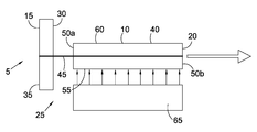
사이드 펌핑 레이저는 출력 커플러(20)와 카운터 반사경(15) 사이에 공급되는 길쭉한 이득 매체(10) 및 이득 매체(10)의 사이드 또는 긴 축을 따라서 이득 매체에 방사를 공급하기 위해 형성된 펌프 소스(65), 펌프 소스로부터의 방사가 이득 매체 위에 직접적으로 투사되는 것과 같이 형성되는 레이저; 및 인접하고, 가깝거나 접촉하고 있는 이득 매체와 접촉하여 공급되는 펌프 소스를 포함한다. 레이저 재료 및 구성 요소들, 기하학적 구조 및 차원들은, 레이저의 성능을 극대화하고 광학 통신 시스템(optical telecoms system)들을 위해 디자인된 장비들의 생산에 평범한 시공 기술의 사용을 가능케 하며 낮은 비용 높은 볼륨 및 소형화를 가능케 하기 위하여 디자인된다. 다른 발산되지 않는 표면(non-emitting surfaces)이 예를 들어 열 전도성에 의한 이득 매체의 펌프 라이트(pump light) 리사이클링(recycling) 및 쿨링(cooling)을 위한 황금 코팅과 함께 코팅되는 동안, 길쭉한 이득 매체(10)는 레이저 다이오드 바(laser diode bar; 65)에 의하여 발산되는 펌프 빛(pump light)을 수용하는 코팅되지 않은 사이드 표면(55)과 함께 횡단면을 가질 수 있다. 카운터 반사경(15)은 수동적인 큐스위치(30)의 일 측면 위에 공급될 수 있고 출력 커플러(20)는 이득 매체(10)의 일 측면(50b) 위에 공급될 수 있다. The side pumping lasers include an elongated gain medium 10 supplied between the output coupler 20 and the counter reflector 15 and a pump source 65 configured to supply radiation to the gain medium along the side or long axis of the gain medium 10. [ ), A laser formed such that radiation from the pump source is projected directly onto the gain medium; And a pump source that is contiguous and supplied in contact with the gain medium in close proximity or in contact. The laser materials and components, geometries and dimensions maximize the performance of the laser and enable the use of common construction techniques in the production of equipment designed for optical telecoms systems, It is designed to enable. While other non-emitting surfaces are coated with a golden coating for pump light recycling and cooling of the gain medium, for example by thermal conductivity, the elongated gain medium The laser diode 10 may have a cross-section with an uncoated side surface 55 that receives pump light emitted by a laser diode bar 65. The counter reflector 15 may be provided on one side of the passive cue switch 30 and the output coupler 20 may be provided on one side 50b of the gain medium 10.
Description
본 발명은 사이드 펌핑 레이저(side pumped laser)에 관한 것이다.
The present invention relates to a side pumped laser.
사이드 펌핑 레이저 시스템(Side pumped laser system)들은 펌프 소스(pump source)로부터 그것의 긴 축에 평행하게 연장되는 이득 매체의 사이드(side)를 따라 길쭉한 이득 매체까지에 공급되는 펌프 방사(pump radiation)가 안에 있는 레이저 시스템(laser system)들이며, 예를 들어, 펌프 방사는 빔(beam) 축에 직각으로 공급된다.Side pumped laser systems have pump radiation supplied to the elongated gain medium along the side of the gain medium extending parallel to its long axis from the pump source For example pump radiation is fed at right angles to the beam axis.
그러나, 사이드 펌핑 레이저 시스템들과 같은 것은 종종 빛 소스(light source)와 이득 매체 사이에서의 펌프 방사의 발산 때문에 비효율적이다. 이러한 문제를 다루기 위하여, 펌프 소스와 이득 매체 사이에서 초점을 맞추거나 빔(beam)을 조준하기 위하여, 원기둥 렌즈(cylindrical lens) 및 포커싱 옵틱스(focussing optics)와 같은, 다양한 광학의 요소들을 공급하는 것은 이 분야에서 일반적인 관례이다. 그러나, 이것은 비용을 증가시키고 잠재적으로 얼라인먼트 문제(alignment issues)를 야기한다.
However, such side-pumping laser systems are often inefficient because of the divergence of pump radiation between the light source and the gain medium. To address this problem, it has been proposed to provide various optical elements, such as a cylindrical lens and focussing optics, to focus or aim the beam between the pump source and the gain medium This is a common practice in this area. However, this increases the cost and potentially causes alignment issues.
적어도 본 발명의 일 실시예가 개선된 사이드 펌핑 레이저를 공급하는 것을 목적으로 한다. 적어도 본 발명의 일 실시예가 적어도 선행 기술의 한 문제점을 제거하거나 완화시키는 것을 목적으로 한다. 특별히, 적어도 본 발명의 일 실시예가 더 작고/작거나 튼튼하고/튼튼하거나 안정적이고/안정적이거나 저비용의 사이드 펌핑 레이저를 공급하는 것을 목적으로 한다.
At least one embodiment of the present invention aims to provide an improved side pumping laser. At least one embodiment of the present invention aims at at least eliminating or alleviating a problem of the prior art. In particular, at least one embodiment of the present invention aims to provide a smaller and / or smaller / more robust / robust / stable / stable or low-cost side pumping laser.
본 발명의 제1관점에 따르면 사이드 펌핑 레이저는:According to a first aspect of the present invention, a side pumping laser comprises:
출력 커플러(output coupler)와 카운터 반사경(counter reflector) 사이에 공급되는 길쭉한 이득 매체; 및An elongated gain medium fed between an output coupler and a counter reflector; And
이득 매체의 사이드 또는 긴 축을 따라서 이득 매체에 방사를 공급하기 위해 형성된 펌프 소스;를 포함한다.And a pump source configured to supply radiation to the gain medium along a side or long axis of the gain medium.
레이저(laser)는 펌프 소스로부터의 방사가 이득 매체 위에 직접적으로 투사(incident)되는 것과 같이 형성될 수 있는데, 예를 들면, 펌프 소스로부터의 빛이 원기둥 렌즈 및/또는 포커싱 옵틱스와 같은 다른 광학의 요소들을 지나가지 않고 이득 매체 위에 투사될 수 있다. A laser can be formed such that radiation from a pump source is incident directly onto a gain medium, for example, when light from a pump source is directed through a cylindrical lens and / or other optics such as focusing optics Can be projected onto the gain medium without passing through the elements.
펌프 소스는 인접하거나 가까운 이득 매체와 접촉하여 공급될 수 있다. 예를 들면, 펌프 소스는 이득 매체의 2미리미터(mm) 사이에, 바람직하게는 1미리미터 사이 그리고 더 바람직하게는 0.2미리미터 사이에 공급될 수 있다. 펌프 소스 및 이득 매체는 밀접하게 연결될 수 있다. The pump source may be supplied in contact with adjacent or near gain media. For example, the pump source may be supplied between 2 millimeters (mm) of the gain medium, preferably between 1 millimeter and more preferably between 0.2 millimeters. The pump source and gain medium can be closely coupled.
펌프 소스는 레이저 다이오드(laser diode)와 같은 빛 소스를 포함할 수 있고, 방사는 빛을 포함할 수 있다. 펌프 소스는 빛 소스의 배열을 포함할 수 있다. 펌프 소스는(예를 들어, 배열) 길쭉하거나 적어도 부분 및 선택적으로 이득 매체의 모든 길이를 따라서 연장될 수 있다. The pump source may include a light source, such as a laser diode, and the radiation may include light. The pump source may comprise an array of light sources. The pump source may be elongated (e.g., in an array) or at least partially and optionally extended along all lengths of the gain medium.
레이저는 이득 매체에 의하여 펌프 소스로부터 수용되는 빛이 발산하도록 형성될 수 있는데, 예를 들면 펌프 방사는 원뿔 형상일 수 있다. 레이저는 펌프 방사가 초점이 맞춰지지 않는 것(non-focussed)과 같이 형성될 수 있다.The laser may be configured to emit light received from a pump source by a gain medium, for example the pump radiation may be conical. The laser can be formed such that the pump radiation is non-focussed.
이득 매체는 에르븀-이테르븀-도핑 유리 막대(Erbium-Ytterbium-doped glass rod)를 포함할 수 있다. 그러나, 다른 이득 매체가 사용될 수 도 있다는 것이 인식될 것이다. The gain medium may comprise an Erbium-Ytterbium-doped glass rod. However, it will be appreciated that other gain media may be used.
이득 매체는 사각 단면과 같은 비원형 또는 비곡선의 횡단면을 지니는 막대를 포함할 수 있는데, 예를 들어, 직각 단면 막대이다. 사각 단면은 원뿔 형상의 펌프 방사에 더 적합하다. 게다가, 펌프 빔(pump beam)은 더 균일한 펌핑(pumping)으로 이어지는 이득 매체와 개선된 레이저 출력 속성(laser output properties)들 사이의 특정한 지점들에 초점이 맞춰지지 않는다.The gain medium may include a rod having a non-circular or non-curved cross-section such as a rectangular cross-section, for example, a rectangular cross-section rod. The square cross section is more suitable for conical pump radiation. In addition, the pump beam is not focused on specific points between the gain medium leading to more uniform pumping and improved laser output properties.
이득 매체는 이득 매체의 평평한 입력 면을 포함할 수 있는 입력 표면을 포함할 수 있다. 입력 표면은 이득 매체의 사이드 또는 길이 방향의 표면을 따라 연장될 수 있고 선택적으로 이득 매체의 길이를 따라서 연장될 수 있다. 입력 표면은 펌프 소스(pump source)와 부합할 수 있다. 입력 표면은 펌프 소스와 직면하고/직면하거나 인접한, 가깝고/가깝거나 접촉하고 있게 공급될 수 있다. 이러한 방식으로, 입력 표면은 펌프 소스로부터 펌프 방사를 수용하도록 배열될 수 있다. 입력 표면은 정사각 단면의 코너(corner)와 같은 이득 매체의 대체되는, 평평해진, 형성되는 또는 제거된 가장자리, 코너 또는 정점을 포함할 수 있다. 입력 표면은 300마이크론 폭(microns wide) 보다 작을 수 있으며, 바람직하게는 200마이크론 폭 보다 더 작으며 더 바람직하게는 100마이크론 폭 보다 더 작을 수 있다. The gain medium may include an input surface that may include a flat input surface of the gain medium. The input surface may extend along a side or longitudinal surface of the gain medium and optionally extend along the length of the gain medium. The input surface can match the pump source. The input surface can be supplied in close proximity, in close proximity, or in contact, facing / facing or adjacent to the pump source. In this way, the input surface can be arranged to receive pump radiation from a pump source. The input surface may include alternating, flattened, formed, or removed edges, corners, or vertices of a gain medium such as a corner of a square cross section. The input surface may be smaller than 300 microns wide, preferably smaller than 200 microns wide, and more preferably smaller than 100 microns wide.
이득 매체는 반사 코팅(reflective coating)과 함께 공급될 수 있다. 반사 코팅은 열전도성이 있을 수 있다. 반사 코팅은 금속 코팅(coating), 바람직하게는 황금 코팅을 포함할 수 있다. 황금 코팅은 이롭게 우수한 반사율 및 열전동성을 공급할 수 있다. 반사 코팅은 이득 매체의 긴 겉면들 또는 표면들(예를 들면, 사이드들) 위에 공급될 수 있다. 입력 표면은 반사 코팅과 함께 코팅되지 않을 수 있거나(다른 말로, 입력 표면이 투명하게 남겨질 수 있다), 투사 펌프 빔(incident pump beam)의 반사를 감소시키기 위해 코팅될 수 있다. The gain medium may be supplied with a reflective coating. The reflective coating may be thermally conductive. The reflective coating may comprise a metallic coating, preferably a golden coating. The golden coating can advantageously provide excellent reflectivity and thermal conductivity. The reflective coating may be applied over long surfaces or surfaces (e.g., sides) of the gain medium. The input surface may not be coated with the reflective coating (in other words, the input surface may be left transparent) and may be coated to reduce reflection of the incident pump beam.
사이드 펌핑 레이저는 펌프 방사가 싱글 티이엠00 모드(single TEM00 mode)의 볼륨(volume)과 일치되는 것과 같이 형성될 수 있다. The side pumping laser may be formed such that the pump emission coincides with the volume of the single TEM 00 mode.
이득 매체의 도핑(doping)은, 예를 들어 민감한 광학의 요소들 또는 코팅들에 광학적 손상을 피하기 위하여, 적어도 이득 매체의 일 차원에 일치하는 빔 스팟 크기(beam spot size)를 야기시키고/야기시키거나 빔(beam)의 출력 밀도가 제어될 수 있다. Doping of the gain medium may cause and / or cause at least beam spot size to coincide with one dimension of the gain medium, for example, to avoid optical damage to sensitive optical elements or coatings. Or the output density of the beam can be controlled.
레이저는 수동적인 큐스위치(Q-switch)와 같은 큐스위치를 포함할 수 있다. 수동적인 큐스위치는 카운터 반사경 또는 출력 커플러와 함께 집적될 수 있다.The laser may include a cue switch such as a passive cue switch (Q-switch). Passive cue switches can be integrated with counter reflectors or output couplers.
카운터 반사경은 유전성의 코팅(dielectric coating)과 같은 고도의 반사 코팅을 포함할 수 있다. 카운터 반사경 또는 출력 커플러는 이득 매체의 단말 및/또는 큐스위치의 외면 위에 공급될 수 있다. The counter reflector may include a highly reflective coating such as a dielectric coating. A counter reflector or output coupler may be provided on the outer surface of the terminal and / or the cue switch of the gain medium.
레이저는 하나 또는 그 이상의 레이저의 요소들을 수용하기 위한 한 하우징(housing) 및/또는 용기를 포함할 수 있다. 하우징 및/또는 용기는 이득 매체, 펌프 소스, 카운터 반사경, 출력 커플러 및/또는 큐스위치를 포함하거나 수용하도록 형성될 수 있다. The laser may comprise a housing and / or a container for receiving one or more elements of the laser. The housing and / or vessel may be configured to contain or contain a gain medium, a pump source, a counter reflector, an output coupler, and / or a cue switch.
이득 매체 및/또는 큐스위치 및/또는 펌프 소스 및/또는 하우징 또는 용기의 적어도 일 차원 및 선택적인 가장 큰 차원은 5센치미터(cm) 보다 작을 수 있고, 바람직하게는 3센치미터 보다 작으며 가장 바람직하게는 2센치미터 보다 작거나 동일하다. At least one dimension and optional largest dimension of the gain medium and / or the cue switch and / or pump source and / or housing or vessel may be less than 5 centimeters (cm), preferably less than 3 centimeters Preferably less than or equal to 2 centimeters.
펌프 소스는 구동 전자 장치(drive electronics) 및/또는 제어 장치를 포함하거나 이와 연결 가능하거나 이와 통신될 수 있다. 구동 전자 장치 및/또는 제어 장치는 하우징 및/또는 용기의 내부 또는 외부에 공급될 수 있다. The pump source may include, be coupled to, or be in communication with drive electronics and / or control devices. The drive electronics and / or control device may be supplied inside or outside the housing and / or the container.
이득 매체, 펌프 소스 및/또는 큐스위치는 하우징 및/또는 용기에 의하여 지지되고/되거나 인접해 있을 수 있다. 하우징 및/또는 용기는 이득 매체, 펌프 소스, 구동 전자 장치 및/또는 제어 장치 및/또는 큐스위치의 적어도 한 결합된 차원에 부합되도록 치수화될 수 있다. The gain medium, the pump source and / or the cue switch may be supported and / or adjacent to the housing and / or the container. The housing and / or container may be dimensioned to conform to at least one combined dimension of the gain medium, the pump source, the drive electronics and / or the control device and / or the cue switch.
하우징 및/또는 용기는 출력 커플러로부터 빔 축(beam axis)에 또는 따라 공급되는 출력 개구와 함께 공급된다.The housing and / or the vessel are supplied with an output opening supplied from or along the beam axis from the output coupler.
하우징 및/또는 용기는 펌프 소스에 힘 및/또는 제어 신호를 제공하기 위하여 전기적 연결을 포함할 수 있다. The housing and / or vessel may include an electrical connection to provide a force and / or control signal to the pump source.
하우징 또는 용기는 열 전도성 물질을 포함할 수 있다. 하우징 또는 용기는 금속 재료, 세라믹 재료(ceramic material) 및/또는 그와 같은 것을 포함할 수 있다. The housing or container may comprise a thermally conductive material. The housing or container may comprise a metallic material, a ceramic material and / or the like.
본 발명의 제2관점에 따르면 장치 또는 시스템은 제1관점의 레이저를 포함할 수 있다. 장치 또는 시스템은 센서(sensor), 레이저 지시기, 거리계, 레이저 일루미네이티드 이미징 시스템(laser illuminated imaging system) 및/또는 그와 같은 것을 포함하거나 포함될 수 있다. According to a second aspect of the present invention, an apparatus or system may comprise a laser of the first aspect. The apparatus or system may include or include a sensor, a laser indicator, a distance meter, a laser illuminated imaging system, and / or the like.
본 발명의 제3관점에 따르면 제1관점에 따라 레이저를 생산하는 방법은, 인접하거나 가까운 이득 매체의 긴 사이드에 접촉된 레이저의 펌프 소스를 공급하는 것을 포함한다. 펌프 소스는, 예를 들어 원기둥 렌즈 및/또는 포커싱 옵틱스를 경유하지 아니하고 직접적으로 이득 매체를 펌프(pump)하기 위하여 배열될 수 있다. According to a third aspect of the present invention, a method of producing a laser according to a first aspect includes supplying a pump source of a laser in contact with the long side of an adjacent or near gain medium. The pump source may be arranged to pump the gain medium directly, for example without passing through a cylindrical lens and / or focusing optics.
방법은 이득 매체 및/또는 펌프 소스 및/또는 큐스위치 및/또는 구동 전자 장치 및/또는 제어 장치를 하우징 및/또는 용기에 설치하는 것을 포함할 수 있다.The method can include installing a gain medium and / or a pump source and / or a cue switch and / or drive electronics and / or control device in the housing and / or the vessel.
어떠한 위의 관점들과 관련된 설명들과 비슷한 특징은 개별적 및 분리적 및/또는 공동적으로 어떠한 다른 관점들에 적용될 수 있다는 것이며, 심지어 그러한 특징들이 다른 특징들과 조합되어 오직 설명될 때도 그러하다. Similar features to descriptions related to any of the above perspectives can be applied to any other perspective, both individually and collectively and / or collectively, even when such features are only described in combination with other features.
방법과 관련하여 위에서 설명된 어떠한 특징을 충족시키기 위하여 형성되는 장치 및/또는 장치 특징과 관련된 위에서 설명된 어떠한 특징의 사용에 상응하는 방법 특징 또한 본 발명의 범위 내에서 속하기 위하여 의도된다.
Method features corresponding to the use of any of the features described above in connection with the apparatus and / or apparatus features formed to satisfy any of the features described above in connection with the method are also intended to fall within the scope of the present invention.
적어도 본 발명의 일 실시예는 개선된 사이드 펌핑 레이저를 공급할 수 있다. 적어도 본 발명의 일 실시예는 적어도 선행 기술의 한 문제점을 제거하거나 완화시킬 수 있다. 특별히, 적어도 본 발명의 일 실시예는 더 작고/작거나 튼튼하고/튼튼하거나 안정적이고/안정적이거나 저비용의 사이드 펌핑 레이저를 공급할 수 있다.
At least one embodiment of the present invention can provide an improved side pumping laser. At least one embodiment of the invention may at least eliminate or alleviate a problem of the prior art. In particular, at least one embodiment of the present invention can provide a smaller / smaller / durable / robust / stable / stable or low cost side pumping laser.
본 발명은 이하의 도면을 참조하여 설명될 것으로:
도1은 레이저 공진기의 정상 면의 도식을 보여주고;
도2는 도1에서 보여지는 레이저 공진기의 측면도의 도식을 보여주고;
도3은 도1에서 보여지는 공진기를 포함하는 레이저의 잘려진 정면도를 보여주며;
도4는 도1의 레이저 공진기 위에 있는 실험 장치를 보여주며;
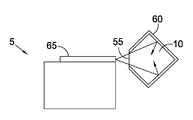
도5는 도4의 장치의 펌프 소스, 큐스위치 및 이득 매체를 보여주는 스케일 이미지(scale image)이며;
도6a는 도4의 장치에 있는 막대의 펌프 지역(pumped region)을 보여주는 이미지(image)이며;
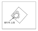
도6b는 도4의 장치에 있는 이득 매체에 관한 레이저 스팟(laser spot)을 보여주는 이미지이며;
도6c는 도4의 장치의 큐스위치 파동을 보여주는 이미지이며;
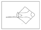
도6d는 도4의 장치에 의해 생산되는 레이저 빔(laser beam)의 원거리 장을 보여주는 이미지이며;
도7은 레이저 공진기 대안의 정상 면의 도식을 보여주고;
도8은 도7에서 보여지는 레이저 공진기의 측면도의 도식을 보여주고; 및
도9는 도7에서 보여지는 레이저 공진기의 측면도 도식의 일 부분을 보여준다. The invention will now be described with reference to the following drawings:
Figure 1 shows a schematic of the top surface of a laser resonator;
FIG. 2 shows a schematic of a side view of the laser resonator shown in FIG. 1;
Figure 3 shows a cut-away front view of the laser including the resonator shown in Figure 1;
Figure 4 shows an experimental apparatus on the laser resonator of Figure 1;
Figure 5 is a scale image showing the pump source, the cue switch and the gain medium of the device of Figure 4;
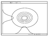
Figure 6a is an image showing the pumped region of the rod in the apparatus of Figure 4;
Figure 6b is an image showing a laser spot on the gain medium in the apparatus of Figure 4;
FIG. 6C is an image showing the cue switch wave of the device of FIG. 4;
Figure 6d is an image showing the far field of a laser beam produced by the apparatus of Figure 4;
Figure 7 shows a schematic of the top surface of a laser resonator alternative;
Figure 8 shows a schematic of a side view of the laser resonator shown in Figure 7; And
FIG. 9 shows a side view of a portion of the laser resonator shown in FIG. 7;
도1에서 도3은 사이드 펌핑 레이저 공진기(side pumped laser resonator; 5)를 보여주는데, 이는 공진 진동(25)를 만들어 내기 위하여 단부 반사경(end reflector; 15)과 부분적으로 반사하는 출력 커플러(output coupler; 20) 사이에 공급되는 이득 매체(10)의 길쭉한 막대를 포함한다. 수동적인 큐스위치(Q-switch; 30)는 단부 반사경(15)와 이득 매체(10) 사이에 공급된다. 이 실험예에서, 단부 반사경(15)은 이득 매체(10)에 대하여 큐스위치(30)의 반대편에 있는 큐스위치(30)의 표면(35) 위에서 코팅(coated)되는데, 큐스위치(30) 및 단부 반사경(15)은 필수적이다. Figures 1 to 3 show a side pumped
의문을 방지하기 위하여, 이득 매체(10)의 반대 단부(50a, 50b)들이 방사상으로(radially) 연장되는 동안, 이득 매체(10)의 사이드(side; 40)들은 이득 매체(10)의 길이 방향의 차원, 빔 축(beam axis; 45)에 평행한 방향으로 연장된다. 이 실험예에서의 이득 매체(10)의 반대 단부(50a, 50b)들은 각각 큐스위치(30) 및 출력 커플러(20)에 마주본다. While the opposite ends 50a and 50b of the
이득 매체(10)는 횡단면을 지니는 막대를 포함하는데, 이는 이득 매체(10)의 사이드(40)의 코너(corner) 대신에 공급되는 길이 방향으로 연장되는 평평한 입력 표면(55)을 제외하고 정사각형의 모양이다. 입력 표면(55)은 이득 매체(10)의 길이를 따라서 상당히 연장된다. 예를 들어, 입력 표면은 300마이크론 폭(microns wide)이다. The
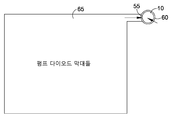
이득 매체(10)의 사이드(40)들의 외면들은 코팅되지 않고 투명한 입력 표면(55)과 함께, 황금 코팅의 형식으로 반사적 및 열 전도성 코팅(60)에 의해 코팅된다. 막대 사이드(40)들 위의 반사 코팅(The reflective coating; 60)은 싱글 티이엠00 모드 볼륨(single TEM00 mode volume)에 알맞은 펌프 소스(pump source; 65)에 의하여 발사되는 갈라지고, 원뿔 형상이며, 초점이 맞춰지지 않은 펌프 방사를 둘러싸고 활용하기 위해 배열될 수 있다. The outer surfaces of the
펌프 소스(65)은 이득 매체(10)의 길이를 따라 길이 방향으로 연장되는 레이저 다이오드 배열(laser diode array)의 모양을 딴 형태이며, 펌프 소스(65)는 원기둥 렌즈 및/또는 포커싱 옵틱스와 같은 어떤 광학 요소 사이를 통과하지 아니한 이득 매체(10)의 입력 표면(55)에 의하여 직접적으로 수용되는 펌프 소스(65)로부터의 빛과 같은 입력 표면(55)에 가깝고 근접하게 연결된다. The
배열을 이용하여, 빔 축(45)은 이득 매체(10)에 공급되는 펌프 방사가 있는 방향에 직각이고 이득 매체(10)의 길이 방향 축에 평행하다.With the arrangement, the
상기 배열은 이득 매체(10)와 펌프 소스(65) 사이의 광학의 필요를 제거하고 갈라지는 빛 소스(light source)가 이득 매체(10)에 직접적이고 효율적으로 연결되는 것이 가능하게 한다. 특별히, 펌프 소스(65)가 이득 매체(10)에 가까이 연결되어 공급되기 때문에, 이득 매체(10)와 펌프 소스(65) 사이의 거리는 최소화되고, 이득 매체(10)와 펌프 소스(65) 사이의 빛의 갈라짐을 최소화한다. 이는 이득 매체(10)와 펌프 소스(65) 사이의 빛의 손실을 최소화한다. 이는 또한 입력 표면(55)의 크기가 최소화되는 것을 가능하게 하며, 코팅되지 않은 입력 표면(55)을 경유하여 이득 매체(10) 사이로부터의 빛의 손실을 최소화한다. 정확히, 도2에서 보여지는 것처럼, 펌핑 방사(pumping radiation)의 갈라짐은 이득 매체(10)안의 방사의 분포를 활용하고 제어하기 위한 이득 매체(10)의 사이드 표면(side surfaces; 40) 위에 방사 코팅(60)을 공급함으로써 활용될 수 있다. 이와 같이, 높은 펌핑 효율(pumping efficiencies)을 달성할 수 있는 단순화된 설계가 공급될 수 있다.This arrangement eliminates the need for optical between the
이득 매체(10)은 이롭게 에르븀-이테르븀-도핑 유리 막대를 포함한다. 그러나, 다른 적합한 이득 매체가 사용될 수 있다. 이득 매체의 도핑은 맞춤 스팟(tailored spot)의 크기를 공급하기 위하여 선택된다. 특별하게, 스팟 크기는 레이저 빔(laser beam) 사이의 어떤 다른 광학 표면 또는 큐스위치(30)에 광학적 손상을 최소화하거나 방지하기 위하여 충분히 낮은 수준을 유지하는 광학 밀도 투사와 같이 제어될 수 있다. The
이득 매체(10)는 반사 코팅(60) 및 열 전도 접착제(heat conducting adhesive; 미도시)를 경유하여 메탈 마운트(metal mount)와 같은 열 전도성이 있는 마운트(mount; 70)에 설치된다. 이러한 방법으로, 황금 반사 코팅(60)은 이득 매체(10)로부터 열 전도 접착제를 경유하여 히트 싱크(heat sink)와 같이 작동하는 마운트(70)로 열을 이동시키는 것을 가능하게 한다. The
도3에서 보여지는 것과 같이, 이득 매체(10), 펌프 소스(65) 및 집적된 큐스위치(30) / 반사경(15)들은 적합한 하우징(75)사이에 설치된다. 선택적으로, 하우징(75)은 열 분산을 개선하기 위한 금속 재료와 같은 열 전도성 재료를 포함한다. 하우징(75)은 출력 커플러(20)와 함께 빔 축(45) 위에 나란히 놓이는 출력 개구(80)와 함께 공급된다. 하우징(75)은 또한 필요한 동력 장치와 제어 연결(85)과 함께 공급된다. 하우징(75)은 레이저 요소들(laser component; 10, 15, 20, 30, 65)이 안에 포함되는 것과 같이 닫힐 수 있다. 3, the
도4는 도1에서 보여지는 레이저 공진기에 상응하여 실험적으로 제공되는 브래드보드(breadboard)를 보여준다. 이러한 경우에, 단부 반사경 반사 표면(15')은 떨어져 있으나 수동적인 큐스위치(30')의 바로 뒤에 공급된다. 이득 매체(10)의 막대는, 도1에 관하여 설명된 것과 같이, 이득 매체(10)의 입력 표면(55)에 가까운 이득 매체(10)의 사이드를 따라 길이 방향으로 연장되는 레이저 다이오드 배열(65)에 의하여 사이드 펌프(side pumped)된다. Fig. 4 shows a breadboard provided experimentally corresponding to the laser resonator shown in Fig. In this case, the end reflector reflective surface 15 'is away but is fed directly behind the passive cue switch 30'. The rod of
레이저 공진기 안에서 사용되기 위한 요소들의 예시가 도5에서 보여진다. 작은 크기의 요소들은 중요하며 이롭다. 도1에서부터 도3에서 보여지는 예에서, 2x1 센치미터(cm)인 레이저 다이오드 배열은 이득 매체(10)의 2센치미터인 긴 막대와 함께 사용되기 위하여 펌프 소스(65)처럼 사용된다. 하우징(75)은 대략 3센치미터 길이다(예를 들어 빔 축(45)에 평행한 방향으로). 도5에서 보여지는 요소들을 위하여, 레이저 다이오드 배열(65)은 대략 0.5센치미터 폭에 1센치미터 길이이며, 큐스위치(30')는 대략 0.5센치미터 평방이며, 이득 매체(10)의 막대는 대략 1센치미터 길이이다. 5센치미터 보다 더 작고, 바람직하게는 3센치미터 보다 더 작고 가장 바람직하게는 2센치미터 이거나 보다 작은 가장 긴 차원을 지니는 이득 매체(10)의 막대, 펌프 다이오드 배열(pump diode array; 65) 및 큐스위치와 같은 요소들의 사용은 종래의 레이저 응용에서 사용되는 종래의 시스템으로부터 탈피(departure from)를 보여주는데 레이저 지시기와 같으며, 그 안에 상당히 더 큰 요소들이 일반적으로 사용된다. 더 작은 요소들 크기는 비용의 절감을 가져온다. 더욱이, 이득 매체(10)의 차원들이 언급된 응용들을 위해 요구되는 출력 빔(output beam)에 더 잘 알맞을 때, 레이저는 더 높은 효율을 갖는다. An example of elements for use in a laser resonator is shown in FIG. Elements of small size are important and beneficial. In the example shown in FIGS. 1 to 3, a laser diode array of 2 x 1 centimeter (cm) is used as
더욱이, 본 디자인(design)은 오직 세 개의 요소들을 포함하는 기본 시스템과 함께 부품의 부족을 위해 주목할 만하다(예를 들어, 펌프 소스(65), 이득 매체(10)의 막대 및 집적된 큐스위치(30) / 단부 반사경(15)). 이들 요소들 각각은 이용할 수 있는 소형화가 가능하다. Moreover, the design is noteworthy for the lack of parts (e. G.,
본 디자인의 소형화된 부품과 함께 작은 요소들의 사용은 섬유 광학 라우터(fibre optic router)들, 멀티 플렉서(multiplexer)들, 스위치(switch)들 및 그와 같은 것들과 같은 광학 통신 시스템(optical telecoms system)들을 위해 디자인된 장비들의 생산에 평범한 시공 기술의 사용을 가능하게 한다. 이와 같은 기술들은 텔레콤(telecom) 기술 분야의 숙련된 사람에게 잘 알려진, 마이크로 머니퓰레이터(micro manipulator)들, 진공 집게들, 인덕션 본딩(induction bonding) 및/또는 이와 같은 것들의 사용을 선택적으로 포함할 수 있다.The use of small elements in conjunction with the miniaturized parts of the present design can be used in optical telecoms systems such as fiber optic routers, multiplexers, switches and the like. ) To enable the use of common construction techniques in the production of equipment designed for them. Such techniques may optionally include the use of micro manipulators, vacuum clamps, induction bonding, and / or the like, well known to those skilled in the telecom art. have.
작은 요소의 크기 및 소형화된 부품의 조합은 또한 매우 컴팩트한 전반적인 패키지(compact overall package)의 결과를 가져온다. The combination of small element size and miniaturized parts also results in a very compact overall package.
그러나, 본 디자인은 쉽게 확장 가능한데, 예를 들어 출력 에너지를 증가시키고, 이득 매체(10)의 막대의 길이를 간단히 증가시키고/증가시키거나 이득 매체(10)의 도핑을 증가시킴으로써 가능하다. 그 이상의 레이저 다이오드들은 또한 펌프 소스(65)에 추가될 수 있다. However, the present design is easily scalable, for example by increasing the output energy, simply increasing / increasing the length of the rod of the
도 6a에서부터 도6d는 도4에서 보여진 실험적 제공을 사용하여 얻어진 결과를 보여준다. 특별히, 도6a는 이득 매체의 막대의 횡단면에서의 펌프 분포를 보여준다. 도6b는 이득 매체의 횡단면에 관한 레이저 스팟(laser spot)의 크기를 보여준다. 도6c는 큐스위치(10) 파동 개요를 보여주고 도6d는 결과로서 생기는 레이저 빔의 원방계 횡단면을 보여준다. 빔 개요는 회절 한계 근처에서 보이는 것으로 알려져 있다.Figures 6A through 6D show the results obtained using the experimental offer shown in Figure 4. In particular, Figure 6a shows the pump distribution in the cross-section of the rod of the gain medium. Figure 6b shows the size of the laser spot relative to the cross-section of the gain medium. Fig. 6C shows a wave outline of the
상기 설명된 본 발명의 이로운 예들에도 불구하고, 위의 변형들이 고려된다.Notwithstanding the beneficial examples of the invention described above, the above variations are contemplated.
예를 들어, 본 발명은 다양한 정도의 효력과 함께, 이 기술 분야에서 알려진 바와 같이, 다양한 적합한 이득 매체 재료들, 펌핑 배열들 및 공진기 차원들과 함께 사용 가능하며 어떤 특별한 형상 또는 차원에 제한되지 않는다. For example, the present invention can be used with a variety of suitable gain media materials, pumping arrangements, and resonator dimensions, and is not limited to any particular shape or dimension, as is known in the art, with varying degrees of effectiveness .
비록 상기에서 설명된 예는 평평한 코너(corner)를 갖는 수정된 정사각형인 횡단면의 개요를 지니는 이득 매체(10) 막대를 가지지만, 이득 매체(10)의 다른 형상들이 사용될 수 있다. 예를 들어, 원형의 횡단면을 지니는 이득 매체(10')의 막대를 포함하는 대체 가능한 레이저 공진기 배열은 도7에서부터 도9에서 보여지는데 여기에서 이득 매체는 단부 받침대들에 의하여 펌프 레이저 마운트(pump laser mount)와 함께 부착된다. 다른 요소들은 도1에서부터 도4에서의 실시예와 관련되어 설명된 것들처럼 상당히 동일하다. Although the example described above has a gain medium 10 bar having an overview of a modified square cross section with flat corners, other shapes of the
더욱이, 이득 매체(10)의 막대는 유리하게 에르븀-이테르븀-도핑 유리 막대인 반면, 다른 적합한 이득 매체가 사용될 수 도 있다. 유사하게, 비록 황금이 반사 코팅(60)을 위해 유리하게 사용되지만, 다른 반사 코팅 또는 다른 기술이 내부 반사 생산을 위하여 사용될 수 있다. Moreover, while the bars of
게다가, 비록 상기 예는 집적된 큐스위치(30) 및 카운터/단부 반사경(15)를 가지고 있는 것과 같이 설명되지만 카운터/단부 반사경(15) 및 큐스위치(30)은 분리되어 공급될 수 있다. 본 발명의 실시예에서 출력 커플러(20) 및/또는 카운터/단부 반사경(15)은 이득 매체(10) 및/또는 큐스위치(30)와 같은 다른 요소들 위에서 코팅된다. 그러나, 이러한 필요가 사실은 아니다. 예를 들어, 출력 커플러(20) 및/또는 카운터/단부 반사경(15)은 분리된 요소들처럼 및/또는 다른 방법에 의하여 공급될 수 있다. In addition, although the above example is described as having an
게다가, 개구는 이득 매체(10) 위의 카운더 반사경 및 큐스위치 위에 형성된 출력 커플러와 같이 뒤집힐 수 있다. In addition, the aperture can be inverted such as the output coupler formed on the caster mirror and the cue switch on the
상기 설명된 레이저 공진기(5)는 센서, 레이저 지시기, 거리계, 레이저 일루미네이티드 이미징 시스템 및/또는 그와 같으나 이에 제한되지 않는 다양한 잠재적인 레이저 기반의 응용 및 장치에서 사용될 수 있다. The
그러므로, 상기 특별한 설명은 오직 한 예로서 공급되는 것이며 발명의 범위는 청구항에 의하여 정의된다.
Therefore, the specific description is provided by way of example only and the scope of the invention is defined by the claims.
Claims (13)
출력 커플러(20)와 카운터 반사경(15) 사이에 공급되는 길쭉한 이득 매체(10); 및
상기 이득 매체(10)의 사이드(40) 또는 긴 축을 따라서 상기 이득 매체(10)에 방사를 공급하기 위해 형성된 펌프 소스(65);
상기 펌프 소스(65)로부터의 방사가 상기 이득 매체(10) 위에 직접적으로 투사되는 것과 같이 형성되는 상기 레이저(5); 및
인접하고, 가깝거나 접촉하고 있는 상기 이득 매체(10)와 접촉하여 공급되는 상기 펌프 소스(65)를
포함하는 사이드 펌핑 레이저(5).
In the side pumping laser 5,
An elongated gain medium (10) supplied between the output coupler (20) and the counter reflector (15); And
A pump source (65) configured to supply radiation to the gain medium (10) along a side (40) or long axis of the gain medium (10);
The laser (5) being formed such that radiation from the pump source (65) is projected directly onto the gain medium (10); And
The pump source 65, which is in contact with and in contact with and in close contact with the gain medium 10,
Including side pumping lasers (5).
상기 레이저(5)는 상기 이득 매체(10)에 의하여 상기 펌프 소스(65)로부터 수용되는 빛이 발산되고 초점이 맞춰지지 않도록 형성되는, 사이드 펌핑 레이저(5).
The method according to claim 1,
Wherein the laser (5) is formed such that light received from the pump source (65) by the gain medium (10) is diverged and not focused.
상기 이득 매체(10)는 직각 단면 막대를 포함하는, 사이드 펌핑 레이저(5).
3. The method according to claim 1 or 2,
Wherein the gain medium (10) comprises a right angle section rod.
상기 이득 매체(10)의 입력 표면(55)이 대체되거나, 평평하거나, 형성되거나 또는 제거된 상기 이득 매체(10)의 가장자리, 코너 또는 정점을 포함하는, 사이드 펌핑 레이저(5).
4. The method according to any one of claims 1 to 3,
The side pumping laser (5) includes an edge, a corner, or a vertex of the gain medium (10) on which the input surface (55) of the gain medium (10) is replaced, flattened, or removed.
상기 이득 매체(10)는 반사적 및/또는 열 전도성 코팅(60)에 의하여 코팅되는, 사이드 펌핑 레이저(5).
5. The method according to any one of claims 1 to 4,
Wherein the gain medium (10) is coated by a reflective and / or thermally conductive coating (60).
상기 펌프 방사는 싱글 티이엠00 모드의 볼륨에 알맞은, 사이드 펌핑 레이저(5).
6. The method according to any one of claims 1 to 5,
The pump radiation is suitable for the volume of the single T-00 mode, side pumping laser (5).
상기 이득 매체(10)의 도핑은 적어도 상기 이득 매체의 일 차원에 대하여 빔 스팟 크기를 맞추고 및/또는 빔의 출력 밀도를 제어할 수 있는, 사이드 펌핑 레이저(5).
7. The method according to any one of claims 1 to 6,
Wherein the doping of the gain medium (10) is capable of adjusting the beam spot size and / or the power density of the beam at least for one dimension of the gain medium.
상기 레이저는 수동적이 큐스위치(30)을 포함하는, 사이드 펌핑 레이저(5).
8. The method according to any one of claims 1 to 7,
Wherein the laser comprises a passive cue switch (30).
적어도 상기 레이저의 어떤 요소들이 안에 수용되는 상기 이득 매체(10) 및/또는 상기 큐스위치(30) 및/또는 상기 펌프 소스(65) 및/또는 하우징 또는 용기(75)의 적어도 가장 큰 차원은 5센치미터 보다 작고, 바람직하게는 3센치미터 보다 더 작으며 가장 바람직하게는 2센치미터 보다 작거나 동일한, 사이드 펌핑 레이저(5).
9. The method according to any one of claims 1 to 8,
At least the largest dimension of the gain medium 10 and / or the queue switch 30 and / or the pump source 65 and / or the housing or vessel 75, in which certain elements of the laser are accommodated, A side pumping laser (5) smaller than the centimeters, preferably less than 3 centimeters, and most preferably less than or equal to 2 centimeters.
사이드 펌프 레이저(5)를 포함하는 장치 또는 시스템.
10. The method according to any one of claims 1 to 9,
An apparatus or system comprising a side pump laser (5).
센서, 레이저 지시기 또는 거리계를 포함하거나 센서, 레이저 지시기 또는 거리계에 포함되는 장치 또는 시스템.
11. The method of claim 10,
A device or system that includes a sensor, laser indicator, or rangefinder, or that is included in a sensor, laser indicator, or rangefinder.
인접하거나 가까운 상기 이득 매체(10)의 긴 사이드에 접촉된 상기 레이저의 상기 펌프 소스(65)를 공급하는 것을 포함하는, 사이드 펌핑 레이저(5)를 생산하는 방법.
10. The method according to any one of claims 1 to 9,
And supplying the pump source (65) of the laser in contact with the long side of the gain medium (10) adjacent or near.
A side pumping laser (5) substantially as shown in the drawings and / or described in the description.
Applications Claiming Priority (3)
| Application Number | Priority Date | Filing Date | Title |
|---|---|---|---|
| GB1217379.5A GB2506402B (en) | 2012-09-28 | 2012-09-28 | Side pumped laser |
| GB1217379.5 | 2012-09-28 | ||
| PCT/GB2013/052121 WO2014049324A1 (en) | 2012-09-28 | 2013-08-08 | Laser diode side pumping of an elongated solid-state laser without focusing|optics |
Publications (1)
| Publication Number | Publication Date |
|---|---|
| KR20150064109A true KR20150064109A (en) | 2015-06-10 |
Family
ID=47225364
Family Applications (1)
| Application Number | Title | Priority Date | Filing Date |
|---|---|---|---|
| KR1020157010710A KR20150064109A (en) | 2012-09-28 | 2013-08-08 | Laser diode side pumping of an elongated solid-state laser without focusing/optics |
Country Status (12)
| Country | Link |
|---|---|
| US (1) | US9525263B2 (en) |
| EP (1) | EP2901530A1 (en) |
| JP (1) | JP2015530756A (en) |
| KR (1) | KR20150064109A (en) |
| CN (1) | CN104798270B (en) |
| AU (1) | AU2013322392A1 (en) |
| CA (1) | CA2886510A1 (en) |
| GB (1) | GB2506402B (en) |
| HK (1) | HK1207213A1 (en) |
| IN (1) | IN2015DN03094A (en) |
| SG (1) | SG11201502446XA (en) |
| WO (1) | WO2014049324A1 (en) |
Cited By (1)
| Publication number | Priority date | Publication date | Assignee | Title |
|---|---|---|---|---|
| KR20230066015A (en) | 2020-09-08 | 2023-05-12 | 고쿠리츠다이가쿠호진 히로시마다이가쿠 | Sperm motility improver and method for improving sperm motility |
Families Citing this family (1)
| Publication number | Priority date | Publication date | Assignee | Title |
|---|---|---|---|---|
| CN112490826B (en) * | 2020-11-06 | 2022-02-18 | 湖北久之洋红外系统股份有限公司 | Erbium glass laser for laser range finder |
Family Cites Families (20)
| Publication number | Priority date | Publication date | Assignee | Title |
|---|---|---|---|---|
| JPS6288386A (en) * | 1985-10-15 | 1987-04-22 | Nec Corp | Semiconductor-laser exciting solid-state laser |
| US5052815A (en) * | 1990-04-13 | 1991-10-01 | Coherent, Inc. | Single frequency ring laser with two reflecting surfaces |
| US5140607A (en) * | 1991-05-23 | 1992-08-18 | Laser Diode, Inc. | Side-pumped laser with angled diode pumps |
| US5249196A (en) * | 1992-05-21 | 1993-09-28 | The United States Of America As Represented By The Secretary Of The Navy | Internally folded scalable laser |
| US5463649A (en) | 1993-08-06 | 1995-10-31 | Sandia Corporation | Monolithically integrated solid state laser and waveguide using spin-on glass |
| FR2715776B1 (en) * | 1994-01-28 | 1996-03-01 | Thomson Csf Semiconducteurs | High power two-stage laser. |
| US5475702A (en) * | 1994-05-31 | 1995-12-12 | General Electric Company | Diode pumped slab module |
| US5774488A (en) * | 1994-06-30 | 1998-06-30 | Lightwave Electronics Corporation | Solid-state laser with trapped pump light |
| US5572541A (en) * | 1994-10-13 | 1996-11-05 | Coherent Technologies, Inc. | Laser rod assembly for side pumped lasers |
| US5867324A (en) * | 1997-01-28 | 1999-02-02 | Lightwave Electronics Corp. | Side-pumped laser with shaped laser beam |
| US6347101B1 (en) * | 1998-04-16 | 2002-02-12 | 3D Systems, Inc. | Laser with absorption optimized pumping of a gain medium |
| US7000213B2 (en) * | 2001-01-26 | 2006-02-14 | Northwestern University | Method and apparatus for automatically generating hardware from algorithms described in MATLAB |
| US6865213B2 (en) * | 2001-03-07 | 2005-03-08 | General Atomics | Diode-pumped solid-state laser in a polyhedronal geometry |
| US7149231B2 (en) * | 2002-10-04 | 2006-12-12 | Spectra Systems Corporation | Monolithic, side-pumped, passively Q-switched solid-state laser |
| US20050074040A1 (en) * | 2003-10-03 | 2005-04-07 | Spence David E. | Diamond cooled laser gain assembly |
| US7388895B2 (en) * | 2003-11-21 | 2008-06-17 | Tsinghua University | Corner-pumping method and gain module for high power slab laser |
| US7729392B2 (en) * | 2005-01-28 | 2010-06-01 | Scientific Materials Corporation | Monoblock laser with reflective substrate |
| US7949022B2 (en) * | 2006-04-27 | 2011-05-24 | Lockheed Martin Corporation | Diode pumping of a laser gain medium |
| EP2443707B1 (en) * | 2009-06-15 | 2015-09-30 | Pantec Biosolutions AG | A monolithic, side pumped solid-state laser and applications thereof |
| EP2474074A1 (en) * | 2009-09-04 | 2012-07-11 | Spectralus Corporation | Efficient and compact visible microchip laser source with periodically poled nonlinear materials |
-
2012
- 2012-09-28 GB GB1217379.5A patent/GB2506402B/en active Active
-
2013
- 2013-08-08 AU AU2013322392A patent/AU2013322392A1/en not_active Abandoned
- 2013-08-08 IN IN3094DEN2015 patent/IN2015DN03094A/en unknown
- 2013-08-08 SG SG11201502446XA patent/SG11201502446XA/en unknown
- 2013-08-08 CN CN201380060851.9A patent/CN104798270B/en active Active
- 2013-08-08 JP JP2015533682A patent/JP2015530756A/en active Pending
- 2013-08-08 WO PCT/GB2013/052121 patent/WO2014049324A1/en active Application Filing
- 2013-08-08 US US14/431,943 patent/US9525263B2/en active Active
- 2013-08-08 CA CA 2886510 patent/CA2886510A1/en not_active Abandoned
- 2013-08-08 KR KR1020157010710A patent/KR20150064109A/en not_active Application Discontinuation
- 2013-08-08 EP EP13750914.7A patent/EP2901530A1/en not_active Withdrawn
-
2015
- 2015-08-06 HK HK15107575.1A patent/HK1207213A1/en unknown
Cited By (1)
| Publication number | Priority date | Publication date | Assignee | Title |
|---|---|---|---|---|
| KR20230066015A (en) | 2020-09-08 | 2023-05-12 | 고쿠리츠다이가쿠호진 히로시마다이가쿠 | Sperm motility improver and method for improving sperm motility |
Also Published As
| Publication number | Publication date |
|---|---|
| EP2901530A1 (en) | 2015-08-05 |
| WO2014049324A1 (en) | 2014-04-03 |
| GB201217379D0 (en) | 2012-11-14 |
| GB2506402B (en) | 2016-02-17 |
| CN104798270B (en) | 2018-01-26 |
| GB2506402A (en) | 2014-04-02 |
| IN2015DN03094A (en) | 2015-10-02 |
| HK1207213A1 (en) | 2016-01-22 |
| US9525263B2 (en) | 2016-12-20 |
| CA2886510A1 (en) | 2014-04-03 |
| JP2015530756A (en) | 2015-10-15 |
| CN104798270A (en) | 2015-07-22 |
| SG11201502446XA (en) | 2015-05-28 |
| US20150263479A1 (en) | 2015-09-17 |
| AU2013322392A1 (en) | 2015-05-14 |
Similar Documents
| Publication | Publication Date | Title |
|---|---|---|
| US11424598B2 (en) | Low cost optical pump laser package | |
| US10243320B2 (en) | Low swap laser pump diode module and laser amplifier incorporating the same | |
| US7949022B2 (en) | Diode pumping of a laser gain medium | |
| US10541508B2 (en) | Diode laser with housing | |
| KR20150064109A (en) | Laser diode side pumping of an elongated solid-state laser without focusing/optics | |
| Ried et al. | Next generation diode lasers with enhanced brightness | |
| US11881676B2 (en) | End-pumped Q-switched laser | |
| CN218549069U (en) | Pump source packaging structure and laser | |
| JP2015056576A (en) | Light-source unit and illumination optical system using light-source unit | |
| JP6130427B2 (en) | Laser module | |
| CN111952837A (en) | Coupling output structure of terahertz quantum cascade laser and packaging method thereof | |
| WO2013153899A1 (en) | Laser device | |
| JP7440492B2 (en) | semiconductor laser equipment | |
| CN218983540U (en) | Miniature laser device | |
| KR100348998B1 (en) | Solid-state laser module with diffusive cavity pumped by radially positioned laser diodes having line shape emitters | |
| JP2015530756A5 (en) | ||
| JP4622396B2 (en) | Laser light source device | |
| JP2011187525A (en) | Semiconductor laser device and method of manufacturing the same | |
| US20180141153A1 (en) | Optical system for focusing a high energy laser | |
| JP2000241659A (en) | Method and device for combining light radiated from multi-mode laser diode | |
| JP6805523B2 (en) | Solid-state laser device | |
| CN114204385A (en) | Solid laser device | |
| KR100387922B1 (en) | Diode-pumped solid-state laser system and optimum pumping method | |
| JP2005064987A (en) | Light receiving element module | |
| JP2014187225A (en) | Laser oscillation device and laser processing machine |
Legal Events
| Date | Code | Title | Description |
|---|---|---|---|
| WITN | Application deemed withdrawn, e.g. because no request for examination was filed or no examination fee was paid |