KR20150064086A - Overmolded medical connector tubing and method - Google Patents
Overmolded medical connector tubing and method Download PDFInfo
- Publication number
- KR20150064086A KR20150064086A KR1020157009718A KR20157009718A KR20150064086A KR 20150064086 A KR20150064086 A KR 20150064086A KR 1020157009718 A KR1020157009718 A KR 1020157009718A KR 20157009718 A KR20157009718 A KR 20157009718A KR 20150064086 A KR20150064086 A KR 20150064086A
- Authority
- KR
- South Korea
- Prior art keywords
- connector
- tube
- overmolded
- receiving cavity
- end member
- Prior art date
Links
Images


Classifications
-
- A—HUMAN NECESSITIES
- A61—MEDICAL OR VETERINARY SCIENCE; HYGIENE
- A61M—DEVICES FOR INTRODUCING MEDIA INTO, OR ONTO, THE BODY; DEVICES FOR TRANSDUCING BODY MEDIA OR FOR TAKING MEDIA FROM THE BODY; DEVICES FOR PRODUCING OR ENDING SLEEP OR STUPOR
- A61M39/00—Tubes, tube connectors, tube couplings, valves, access sites or the like, specially adapted for medical use
- A61M39/08—Tubes; Storage means specially adapted therefor
-
- A—HUMAN NECESSITIES
- A61—MEDICAL OR VETERINARY SCIENCE; HYGIENE
- A61M—DEVICES FOR INTRODUCING MEDIA INTO, OR ONTO, THE BODY; DEVICES FOR TRANSDUCING BODY MEDIA OR FOR TAKING MEDIA FROM THE BODY; DEVICES FOR PRODUCING OR ENDING SLEEP OR STUPOR
- A61M39/00—Tubes, tube connectors, tube couplings, valves, access sites or the like, specially adapted for medical use
- A61M39/10—Tube connectors; Tube couplings
- A61M39/12—Tube connectors; Tube couplings for joining a flexible tube to a rigid attachment
-
- B29C47/0023—
-
- B29C47/0028—
-
- B29C47/0033—
-
- B29C47/021—
-
- B29C47/065—
-
- B—PERFORMING OPERATIONS; TRANSPORTING
- B29—WORKING OF PLASTICS; WORKING OF SUBSTANCES IN A PLASTIC STATE IN GENERAL
- B29C—SHAPING OR JOINING OF PLASTICS; SHAPING OF MATERIAL IN A PLASTIC STATE, NOT OTHERWISE PROVIDED FOR; AFTER-TREATMENT OF THE SHAPED PRODUCTS, e.g. REPAIRING
- B29C48/00—Extrusion moulding, i.e. expressing the moulding material through a die or nozzle which imparts the desired form; Apparatus therefor
- B29C48/03—Extrusion moulding, i.e. expressing the moulding material through a die or nozzle which imparts the desired form; Apparatus therefor characterised by the shape of the extruded material at extrusion
- B29C48/09—Articles with cross-sections having partially or fully enclosed cavities, e.g. pipes or channels
- B29C48/11—Articles with cross-sections having partially or fully enclosed cavities, e.g. pipes or channels comprising two or more partially or fully enclosed cavities, e.g. honeycomb-shaped
-
- B—PERFORMING OPERATIONS; TRANSPORTING
- B29—WORKING OF PLASTICS; WORKING OF SUBSTANCES IN A PLASTIC STATE IN GENERAL
- B29C—SHAPING OR JOINING OF PLASTICS; SHAPING OF MATERIAL IN A PLASTIC STATE, NOT OTHERWISE PROVIDED FOR; AFTER-TREATMENT OF THE SHAPED PRODUCTS, e.g. REPAIRING
- B29C48/00—Extrusion moulding, i.e. expressing the moulding material through a die or nozzle which imparts the desired form; Apparatus therefor
- B29C48/03—Extrusion moulding, i.e. expressing the moulding material through a die or nozzle which imparts the desired form; Apparatus therefor characterised by the shape of the extruded material at extrusion
- B29C48/13—Articles with a cross-section varying in the longitudinal direction, e.g. corrugated pipes
-
- B—PERFORMING OPERATIONS; TRANSPORTING
- B29—WORKING OF PLASTICS; WORKING OF SUBSTANCES IN A PLASTIC STATE IN GENERAL
- B29C—SHAPING OR JOINING OF PLASTICS; SHAPING OF MATERIAL IN A PLASTIC STATE, NOT OTHERWISE PROVIDED FOR; AFTER-TREATMENT OF THE SHAPED PRODUCTS, e.g. REPAIRING
- B29C48/00—Extrusion moulding, i.e. expressing the moulding material through a die or nozzle which imparts the desired form; Apparatus therefor
- B29C48/15—Extrusion moulding, i.e. expressing the moulding material through a die or nozzle which imparts the desired form; Apparatus therefor incorporating preformed parts or layers, e.g. extrusion moulding around inserts
- B29C48/151—Coating hollow articles
-
- B—PERFORMING OPERATIONS; TRANSPORTING
- B29—WORKING OF PLASTICS; WORKING OF SUBSTANCES IN A PLASTIC STATE IN GENERAL
- B29C—SHAPING OR JOINING OF PLASTICS; SHAPING OF MATERIAL IN A PLASTIC STATE, NOT OTHERWISE PROVIDED FOR; AFTER-TREATMENT OF THE SHAPED PRODUCTS, e.g. REPAIRING
- B29C48/00—Extrusion moulding, i.e. expressing the moulding material through a die or nozzle which imparts the desired form; Apparatus therefor
- B29C48/16—Articles comprising two or more components, e.g. co-extruded layers
- B29C48/18—Articles comprising two or more components, e.g. co-extruded layers the components being layers
- B29C48/21—Articles comprising two or more components, e.g. co-extruded layers the components being layers the layers being joined at their surfaces
-
- A—HUMAN NECESSITIES
- A61—MEDICAL OR VETERINARY SCIENCE; HYGIENE
- A61M—DEVICES FOR INTRODUCING MEDIA INTO, OR ONTO, THE BODY; DEVICES FOR TRANSDUCING BODY MEDIA OR FOR TAKING MEDIA FROM THE BODY; DEVICES FOR PRODUCING OR ENDING SLEEP OR STUPOR
- A61M39/00—Tubes, tube connectors, tube couplings, valves, access sites or the like, specially adapted for medical use
- A61M39/08—Tubes; Storage means specially adapted therefor
- A61M2039/082—Multi-lumen tubes
-
- B29C2947/92761—
-
- B—PERFORMING OPERATIONS; TRANSPORTING
- B29—WORKING OF PLASTICS; WORKING OF SUBSTANCES IN A PLASTIC STATE IN GENERAL
- B29C—SHAPING OR JOINING OF PLASTICS; SHAPING OF MATERIAL IN A PLASTIC STATE, NOT OTHERWISE PROVIDED FOR; AFTER-TREATMENT OF THE SHAPED PRODUCTS, e.g. REPAIRING
- B29C2948/00—Indexing scheme relating to extrusion moulding
- B29C2948/92—Measuring, controlling or regulating
- B29C2948/92504—Controlled parameter
- B29C2948/92514—Pressure
-
- B—PERFORMING OPERATIONS; TRANSPORTING
- B29—WORKING OF PLASTICS; WORKING OF SUBSTANCES IN A PLASTIC STATE IN GENERAL
- B29C—SHAPING OR JOINING OF PLASTICS; SHAPING OF MATERIAL IN A PLASTIC STATE, NOT OTHERWISE PROVIDED FOR; AFTER-TREATMENT OF THE SHAPED PRODUCTS, e.g. REPAIRING
- B29C2948/00—Indexing scheme relating to extrusion moulding
- B29C2948/92—Measuring, controlling or regulating
- B29C2948/92504—Controlled parameter
- B29C2948/92761—Mechanical properties
Abstract
고압 의료용 커넥터 배관 조립체는, 서로 반대측의 튜브 단부들 및 통로를 포함하는 튜브 부재; 서로 반대측의 튜브 단부들 중 적어도 하나에 오버몰딩되며, 미리 선택된 길이를 가지는 환형 끝단 부분을 포함하는 단부 부재; 및 수용 캐비티를 정의하는 커넥터 허브를 포함하는 커넥터 부재를 포함한다. 환형 끝단 부분의 미리 선택된 길이는 커넥터 허브에서 응력이 집중되는 축방향 위치를 미리 제어하는 데에 이용될 수 있다. 고압 의료용 커넥터 배관 조립체의 형성 방법은, 서로 반대측의 튜브 단부들 및 통로를 포함하는 튜브 부재를 제공하는 단계; 서로 반대측의 튜브 단부들 중 적어도 하나에 단부 부재를 오버몰딩하는 단계; 수용 캐비티를 정의하는 커넥터 허브를 포함하는 커넥터 부재를 제공하는 단계; 및 오버몰딩된 단부 부재를 구비한 튜브 단부를 수용 캐비티에 고정하는 단계를 포함한다.The high pressure medical connector tubing assembly includes: a tubular member including opposite tube ends and passages; An end member overmolded onto at least one of the tube ends opposite to each other and including an annular end portion having a preselected length; And a connector member including a connector hub defining a receiving cavity. The preselected length of the annular end portion can be used to pre-control the axial position at which stress is concentrated in the connector hub. A method of forming a high pressure medical connector tubing assembly comprises the steps of: providing a tubular member comprising opposite tube ends and passageways; Overmolding the end member to at least one of the tube ends opposite to each other; Providing a connector member including a connector hub defining an accommodation cavity; And fixing the tube end with the overmolded end member to the receiving cavity.

Description
본 발명은 의료 분야, 구체적으로, 의료 분야에서 환자와의 사이에 및/또는 환자와의 사이에 유체를 안내하기 위해 유체 연결부를 형성하기 위한 하나 이상의 단부 커넥터를 포함할 수 있는 의료 기기 사이에 유체를 안내하기 위해 사용되는 의료용 배관에 관한 것이다.The present invention relates to a medical device, particularly a medical device, which may include one or more end connectors for forming a fluid connection to guide fluid between the patient and / or the patient in the medical field The present invention relates to a medical piping used for guiding a patient.
의료용 배관과 이를 위한 커넥터의 수많은 예들을 의료 분야에서 찾아볼 수 있다. 예를 들어, 미국 특허 출원 공개 제2012/0024411호(Hahn et al.)는 전반적으로, 액체 크로마토그래피의 구성요소들 및 다른 분석 시스템을 연결하는 데 사용되는 배관에 관한 것으로, 외부층, 내부층 및 내부층에 의해 정의되는 통로를 포함한 3개의 별개의 부분들로 이루어지는 배관을 개시한다. 배관은 외부층의 단부 상에 기계가공된, 바브와 같은 유지 특징부를 포함한다. 내부층은 바브로부터 돌출되며, 바브 및 내부층의 돌출부는 선단부와 함께 오버몰딩된다.Numerous examples of medical tubing and connectors therefor can be found in the medical field. For example, U.S. Patent Application Publication No. 2012/0024411 (Hahn et al.) Generally relates to piping used to connect components of liquid chromatography and other analytical systems, including an outer layer, an inner layer And three separate portions including a passage defined by the inner layer. The tubing includes a retaining feature, such as a barb, machined on the end of the outer layer. The inner layer is projected from the barb and the projections of the barb and inner layer are overmolded with the leading edge.
미국 특허 출원 제2011/0306826호(Franklin et al.)는, 배관에 구멍이 나는 것을 방지하기 위해 의료 시스템에 사용되는 삽입 가능 장치를 개시한다. 일 실시예에서, 튜브에 오버몰딩되거나 튜브뿐만 아니라 튜브 단부에 연결된 하우징에 오버몰딩되는 차폐 장치가 제공된다.U.S. Patent Application No. 2011/0306826 (Franklin et al.) Discloses an insertable device for use in a medical system to prevent puncturing of the tubing. In one embodiment, a shielding device is provided that overmolds the tube or overmolds the tube as well as the housing connected to the tube end.
미국 특허 출원 제2011/0127186호(Enns et al.)는 카테터 및 안내 와이어와 같은 가늘고 긴 의료 장치를 위한 패키징 튜브를 개시하며, 이 때 일련의 플라스틱 클립들이 튜브 상에 오버몰딩된다. 각각의 클립들은 튜브의 인접한 부분들을 둘러싸고 폐루프를 형성하여, 클립이 위치된 각각의 부분에서 튜브의 외측 표면을 둘러싼다.U.S. Patent Application No. 2011/0127186 (Enns et al.) Discloses a packaging tube for an elongated medical device, such as a catheter and a guidewire, wherein a series of plastic clips are overmolded onto the tube. Each clip surrounds adjacent portions of the tube and forms a closed loop, surrounding the outer surface of the tube at each portion where the clip is located.
미국 특허 출원 공개 제2010/0130922호(Borlaug et al.)는 오버몰딩된 열가소성 엘라스토머로 만들어진 유체 커넥터들을 포함하는 의료용 유체 주입 장치를 개시한다.U.S. Patent Application Publication No. 2010/0130922 (Borlaug et al.) Discloses a medical fluid injection device comprising fluid connectors made of an overmolded thermoplastic elastomer.
미국 특허 출원 공개 제2010/0063481호(Hoffman et al.)는 의료용 유체의 전달을 위한 유로에 사용되는 유로 조립체를 개시한다. 이 공개문헌은 일 단부가 주사기 출구에 연결된 배관을 개시하며, 반대측 단부에 연결된 압축 가능한 밀봉 부재를 구비한다. 밀봉 부재는 엘라스토머 재료로 형성될 수 있고, 대체로 원통형인 형상을 가지며 배관과 중심이 같도록 치수가 정해진다. 엘라스토머 밀봉 부재는 배관 상에 오버몰딩되어 접착제의 필요성을 없앨 수 있다.U.S. Patent Application Publication No. 2010/0063481 (Hoffman et al.) Discloses a flow path assembly for use in a flow path for delivery of a medical fluid. This publication discloses a piping having one end connected to the outlet of the syringe and having a compressible sealing member connected to the opposite end. The sealing member can be formed of an elastomeric material, has a generally cylindrical shape and is dimensioned to be centered with the tubing. The elastomeric sealing member may be overmolded on the piping to eliminate the need for an adhesive.
미국 특허 출원 공개 제2010/0022966호(Kennard)는 오버몰딩된 영역을 가진 배관을 포함하는 유체 전달 장치를 개시하며, 압축 끼워맞춤에 의해, 바브가 형성된 커넥터 단부가 오버몰딩된 영역에 고정될 수 있다.U.S. Patent Application Publication No. 2010/0022966 (Kennard) discloses a fluid delivery device comprising a tubing with an overmolded region, by which a barbed connector end can be secured in an overmolded region have.
미국 특허 출원 공개 제2008/0284167호(Lim et al.)는 배관을 연결하기 위한 부품을 개시한다. 일 실시예에서, 부품은 사출 성형으로 형성되고, 그 후 부품 상에 재료가 오버몰딩 또는 공동 몰딩되어 연장 부분을 형성한 후, 튜브 단부가 부품 내에 삽입되어 부품을 통해 유체를 안내한다.United States Patent Application Publication No. 2008/0284167 (Lim et al.) Discloses a component for connecting piping. In one embodiment, the part is formed by injection molding, and after the material is overmolded or cavity-molded on the part to form an extension, the tube end is inserted into the part to guide the fluid through the part.
미국 특허 출원 공개 제2007/0215268호(Pingleton)는 튜브에 브레이드(braid)를 적용하고 브레이드를 튜브에 융합시켜 뒤틀림(kinking) 등을 방지하는 방법을 개시한다. 브레이드는 튜브에 인서트 몰딩 또는 오버몰딩될 수 있다.U.S. Patent Application Publication No. 2007/0215268 (Pingleton) discloses a method of applying a braid to a tube and fusing the braid to the tube to prevent kinking or the like. The braid can be insert molded or overmolded into the tube.
미국 특허 출원 공개 제2006/0170134호(Rowley et al.)는 배관 세그먼트를 가진 커넥터를 사출 오버몰딩하는 방법을 개시한다.U.S. Patent Application Publication No. 2006/0170134 (Rowley et al.) Discloses a method of overmolding a connector with a piping segment.
본 발명은 오버몰딩된 의료용 커넥터 배관 및 방법을 제공한다.The present invention provides overmolded medical connector tubing and methods.
본원에 기술된 일 실시예는, 서로 반대측의 튜브 단부들 및 통로를 포함하는 튜브 부재, 서로 반대측의 튜브 단부들 중 적어도 하나에 오버몰딩되며 미리 선택된 길이를 가지는 환형 끝단 부분을 포함하는 단부 부재, 및 오버몰딩된 단부 부재를 구비한 튜브 단부가 고정된 수용 캐비티를 정의하는 커넥터 허브를 포함하는 커넥터 부재를 포함하는, 고압 의료용 커넥터 배관 조립체에 관한 것이다. 환형 끝단 부분의 미리 선택된 길이는 커넥터 허브에서 응력이 집중되는 축방향 위치를 미리 제어하는 데에 이용될 수 있다.One embodiment described herein is a tube member comprising tube members comprising opposite tube ends and passageways, end members overmolded on at least one of the tube ends opposite to each other and including an annular end portion having a preselected length, And a connector hub including a connector hub defining a receiving cavity to which a tube end with an overmolded end member is secured. The preselected length of the annular end portion can be used to pre-control the axial position at which stress is concentrated in the connector hub.
오버몰딩된 단부 부재를 구비한 튜브 단부는 용매 결합에 의해 수용 캐비티에 고정될 수 있다. 단부 부재에는 적어도 하나의 외측 표시기가 형성되어, 수용 캐비티에 오버몰딩된 단부 부재를 구비한 튜브 단부가 삽입되는 깊이를 시각적으로 확인할 수 있다. 튜브 부재는, 가요성 폴리머층으로 캡슐화된 내부 브레이드로 형성된 브레이드 배관을 포함할 수 있다. 커넥터 부재는 유체 통로를 정의하는 커넥터 포트를 포함할 수 있다. 환형 끝단 부분은 유체 통로에서 튜브 부재의 통로까지 테이퍼지는 테이퍼 입구를 정의할 수 있다. 입구는 예컨대 0° 내지 80°의 각도로 내측으로 테이퍼질 수 있다. 튜브 부재의 튜브 단부들 각각에 단부 부재가 오버몰딩된다. 커넥터 부재는 한 쌍의 커넥터 부재를 포함할 수 있고, 튜브 단부는 각각 커넥터 부재의 수용 캐비티에 각각 고정된 오버몰딩된 단부 부재를 가진다. 튜브 부재는 가요성 폴리머층에 의해 캡슐화된 내부 브레이드로 형성된 브레이드 배관을 포함할 수 있다.The tube end with the overmolded end member can be secured to the receiving cavity by solvent bonding. At least one outer indicator is formed on the end member to visually identify the depth into which the tube end with the overmolded end member is inserted. The tubular member may comprise a braid tubing formed of an inner braid encapsulated with a flexible polymer layer. The connector member may include a connector port defining a fluid passage. The annular end portion may define a tapered inlet that tapers from the fluid passage to the passage of the tube member. The inlet may be tapered inward at an angle of, for example, 0 ° to 80 °. An end member is overmolded at each of the tube ends of the tube member. The connector member may include a pair of connector members, and the tube ends each have an overmolded end member secured to the receiving cavity of the connector member, respectively. The tubular member may comprise a braid tubing formed of an inner braid encapsulated by a flexible polymer layer.
또 다른 실시예는, 서로 반대측의 튜브 단부 및 통로를 포함하는 튜브 부재를 제공하는 단계, 서로 반대측의 튜브 단부들 중 적어도 하나 상에, 미리 선택된 길이를 갖는 환형 끝단 부분을 포함하는 단부 부재를 오버몰딩하는 단계, 수용 캐비티를 정의하는 커넥터 허브를 포함하는 커넥터 부재를 제공하는 단계, 및 오버몰딩된 단부 부재를 구비한 튜브 단부를 수용 캐비티에 고정하는 단계를 포함하는, 고압 의료용 커넥터 배관 조립체의 형성 방법에 관한 것이다. 환형 끝단 부분의 미리 선택된 길이는, 커넥터 허브에서 응력이 집중되는 축방향을 미리 제어하는 데에 사용될 수 있다.Yet another embodiment provides a method of making a tube member comprising providing a tube member comprising opposite tube ends and passageways, applying an end member comprising an annular end portion having a preselected length onto at least one of the tube ends opposite to each other, Forming a high-pressure medical connector tubing assembly, the method comprising: providing a connector member including a connector hub defining a receiving cavity; and securing the tubing end with the overmolded end member to a receiving cavity. ≪ / RTI > The pre-selected length of the annular end portion can be used to pre-control the axial direction in which stress is concentrated in the connector hub.
오버몰딩된 단부 부재를 구비한 튜브 단부를 수용 캐비티에 고정하는 단계는 용매 결합을 포함할 수 있다. 단부 부재에는 적어도 하나의 외측 표시기가 형성되어, 오버몰딩된 단부 부재를 구비한 튜브 단부가 수용 캐비티에 삽입되는 깊이를 시각적으로 확인할 수 있다. 튜브 부재는, 가요성 폴리머층으로 캡슐화된 내부 브레이드로 형성된 브레이드 배관을 포함할 수 있다. 커넥터 부재는 유체 통로를 정의하는 커넥터 포트를 포함할 수 있다. 환형 끝단 부분은 유체 통로에서 튜브 부재의 통로까지 테이퍼지는 테이퍼 입구를 정의할 수 있다. 입구는 예컨대 0° 내지 80°의 각도로 내측으로 테이퍼질 수 있다. 튜브 부재의 튜브 단부들 각각에 단부 부재가 오버몰딩될 수 있다. 튜브 단부는 각각 오버몰딩된 단부 부재를 가질 수 있으며, 커넥터 부재의 수용 캐비티에 각각 고정된다. 튜브 부재는 가요성 폴리머층에 의해 캡슐화된 내부 브레이드로 형성된 브레이드 배관을 포함할 수 있다.The step of securing the tube end with the overmolded end member to the receiving cavity may comprise solvent bonding. At least one outer indicator is formed in the end member to visually identify the depth at which the tube end with the overmolded end member is inserted into the receiving cavity. The tubular member may comprise a braid tubing formed of an inner braid encapsulated with a flexible polymer layer. The connector member may include a connector port defining a fluid passage. The annular end portion may define a tapered inlet that tapers from the fluid passage to the passage of the tube member. The inlet may be tapered inward at an angle of, for example, 0 ° to 80 °. An end member can be overmolded at each of the tube ends of the tube member. The tube ends may each have an overmolded end member and are each secured to a receiving cavity of the connector member. The tubular member may comprise a braid tubing formed of an inner braid encapsulated by a flexible polymer layer.
첨부 도면과 함께 하기의 상세한 설명으로부터 본 발명의 추가 상세사항 및 이점을 이해하게 될 것이다.BRIEF DESCRIPTION OF THE DRAWINGS Further details and advantages of the present invention will become apparent from the following detailed description, taken in conjunction with the accompanying drawings.
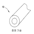
도 1a 내지 도 1c는 의료 분야에서 사용되는 공지된 의료용 배관의 단부 사시도이다.
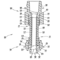
도 2는 일 실시예에 따른 오버몰딩된 의료용 커넥터 배관 조립체의 단면도이다.
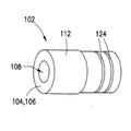
도 3은 도 2에 도시된 의료용 커넥터 배관 조립체에 사용되는 튜브 부재의 등각 투영도이다.
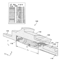
도 4는 일단 오버몰딩된 튜브 부재와 조립된 상태에서, 도 2에 도시된 의료용 커넥터 배관 조립체의 예시적인 커넥터 부재의 유한 요소 해석(FEA) 도표이다.
도 5는 유체 압력 하에서의 조립된 커넥터 부재와 튜브 부재의 유한 요소 해석(FEA) 도표이다.
도 6은 조립된 커넥터 부재 및 튜브 부재의 예시적인 제1 변형예에 따른 도 2의 의료용 커넥터 배관 조립체의 단면도이다.
도 7은 조립된 커넥터 부재 및 튜브 부재의 예시적인 제2 변형예에 따른 도 2의 의료용 커넥터 배관 조립체의 단면도이다.
도 8은 조립된 커넥터 부재 및 튜브 부재의 예시적인 제2 변형예에 따른 도 2의 의료용 커넥터 배관 조립체의 단면도이다.Figures 1A-1C are end perspective views of known medical tubing used in the medical field.
2 is a cross-sectional view of an overmolded medical connector tubing assembly in accordance with one embodiment.
3 is an isometric view of the tubular member used in the medical connector tubing assembly shown in Fig.
4 is a finite element analysis (FEA) diagram of an exemplary connector member of the medical connector tubing assembly shown in FIG. 2, once assembled with an overmolded tubular member.
5 is a finite element analysis (FEA) diagram of assembled connector and tube members under fluid pressure.
Figure 6 is a cross-sectional view of the medical connector piping assembly of Figure 2 according to a first modified version of an assembled connector member and a tubular member.
Figure 7 is a cross-sectional view of the medical connector piping assembly of Figure 2 according to a second alternate embodiment of an assembled connector member and a tubular member.
Figure 8 is a cross-sectional view of the medical connector piping assembly of Figure 2 according to a second alternate embodiment of an assembled connector member and a tubular member.
이하, 설명의 목적 상, 사용된 바와 같은 공간 배향에 관한 용어들은, 첨부 도면에서 배향되거나 또는 하기의 상세한 설명에서 설명됨에 따라 참조된 실시예들과 관련된다. 그러나, 이하에 설명된 실시예들은 많은 대안적인 변형예 및 구성예들을 상정할 수 있음을 이해할 것이다. 또한 첨부 도면에서 예시되고 본원에서 설명된 특정 구성요소, 장치, 특징부 및 작동 시퀀스는 단순히 예시적인 것이며 제한적으로 해석되어서는 안 된다는 것을 이해할 것이다.Hereinafter, for purposes of explanation, terms relating to spatial orientation as used herein are related to the embodiments referenced in the accompanying drawings or as described in the following detailed description. However, it will be appreciated that the embodiments described below may assume many alternative variations and configurations. It is also to be understood that the particular components, devices, features and operating sequences illustrated in the accompanying drawings and described herein are exemplary only and are not to be construed as limiting.
도 1a 내지 도 1c를 참조하면, 의료 분야에서, 커넥터 단부를 구비한 고압 배관을 위한 몇 가지 선택지가 이용 가능하다. 도 1a에서, 의료용 배관(10)은 고압 PVC 배관의 형태로 도시된다. 이러한 공지된 구성에서, 일단 고가의 전용 생산 사출 성형 공구가 제자리에 준비되면, 제조 비용은 낮은 것으로 여겨진다. 의료용 배관(10)은, 튜브를 연식(non-rigid)으로 만들기 위해 가소제를 포함하는 단일 벽 플라스틱 폴리머를 필요로 한다. 이러한 가소제들은 의료 분야에서 생체 적합성 및 유로 내로의 이동 가능성과 관련하여 면밀한 검토 하에 있다. 또한, 작동 압력은 조작 등급 플라스틱에 대한 PVC의 낮은 인장 강도로 인해 보통 1000 psi로 제한된다. 일반적인 응용에서, 의료용 배관(10)의 단부에 루어 허브가 용매 결합될 수 있다. 용매 결합은 루어 응력으로 인한 미세 균열 크랙 형성 문제를 야기하는 것으로 알려져 있으며, 루어 허브가 의료용 배관(10)의 단부에 용매-결합될 때 루어 허브의 표면에 미세한 크랙이 나타난다. 이렇게 유발된 크랙 형성은, 억지 끼워맞춤 및 용매-결합을 필요로 하는 의료용 배관(10)의 단부에 단부 커넥터가 적용될 때, 높은 경도계의 강성 배관으로 발생한 높은 응력으로 인한 것이다. 이러한 억지 끼워맞춤 및 수반되는 용매 결합 공격은 공기 침투 및/또는 압력 손실로 이어질 수 있다. 자외선(UV) 접착제 결합은 용매 결합에 대한 대안으로서 신뢰할만하지 않은데, 그 이유는 가소제가 UV 접착제를 공격하며 멸균 후 결합된 연결부를 박리시킬 수 있기 때문이다. 루어 커넥터 부품을 의료용 배관(10)의 단부 상에 인서트 몰딩할 수 있지만, 제조 비용이 증가하고, 커넥터 기하구조가 단순한 일직선 유로에 한정된다.Referring to Figures 1A-1C, in the medical field, several options are available for high pressure tubing with a connector end. In Figure 1A, the
도 1b에는, 공압출된 고압 커넥터 배관 형태의 의료용 배관(20)이 도시된다. 의료용 배관(20)은 적합한 폴리머로 형성된 고강도 내벽(22)을 구비하며, 이러한 내벽은 또 다른 폴리머로 형성된 가요성 외벽(24)에 의해 동축으로 둘러싸이고, 이에 따라 의료용 배관은 1200 psi 등급을 달성할 수 있으면서도 어느 정도의 가요성을 유지한다. 이 실시예에서, 의료용 배관(20)의 단부에 루어 허브가 용매-결합될 수 있지만, 의료용 배관(20)에 대한 직접적인 용매 결합은, 상술한 의료용 배관(10)과 유사한 방식으로 루어 허브 응력으로 인한 미세 균열 및 크랙 형성 문제를 야기하기도 한다. 이렇게 유발된 크랙 형성은, 억지 끼워맞춤 및 용매 결합을 필요로 하는 의료용 배관(20)의 단부에 단부 커넥터가 적용될 때 중간 응집 경도계 배관으로 발생한 높은 응력으로 인한 것이다. 이러한 억지 끼워맞춤 및 수반되는 용매 결합 공격은 공기 침투 및/또는 압력 손실로 이어질 수 있다. 또한 자외선(UV) 접착제 결합은 용매 결합에 대한 대안으로서 신뢰할만하지 않은데, 그 이유는 UV 접착제는 최적의 강도를 위해 의료용 배관(20)과 루어 허브 사이에 간극을 필요로 하고 시간 경과에 따른 접착제 결합 붕괴로 인해 저장 수명이 제한되기 때문이다. 루어 커넥터 부품을 의료용 배관(20)의 단부 상에 인서트 몰딩할 수 있지만, 역시 제조 비용이 증가하고, 커넥터 기하구조가 단순한 일직선 유로에 한정된다.1B, a
도 1c에는, 브레이드 고압 커넥터 배관 형태의 의료용 배관(30)이 도시된다. 의료용 배관(30)은 가요성 폴리머층(34)에 캡슐화된 적합한 폴리머로 형성된 고강도 내부 브레이드(32)를 구비하여, 높은 등급의 가요성과 함께 1200 psi 압력 등급을 달성한다. 내부 브레이드(32)는 의료용 배관(30)이 팽창 및 파열되는 것을 막지만, 에어-퍼지 작업 후 기포 가시화를 보장하기 위해 종종 이용되는 시각적 유로 투명도를 저해할 수 있다. 또한, 브레이드 의료용 배관(30)이 절단된 경우, 유체 압력이 브레이드 내로 흡상(wick)되는 것(의료용 배관(30)의 압력 손실을 야기할 수 있음)을 막기 위해 절단된 단부를 고압으로부터 분리하는 것이 바람직하다. 앞에서 논의된 실시예에서와 같이 직접적인 용매 결합은 루어 허브 응력으로 인한 미세 균열 및 크랙 형성 문제를 야기할 수 있다. 이렇게 유발된 크랙 형성은, 억지 끼워맞춤 및 용매 결합을 필요로 하는 의료용 배관(30)의 단부에 단부 커넥터가 적용될 때 발생한 높은 응력으로 인한 것이다. 브레이드 의료용 배관(30)을 루어 허브 내에 집어 넣고, 브레이드 단부 내로 가압 액체가 흡상되는 것(의료용 배관(30)의 압력 손실을 야기할 수 있음)을 막기 위해 필요한 억지 끼워맞춤의 정도로 인해 응력이 높다. 역시 마찬가지로, 자외선(UV) 접착제 결합은 용매 결합에 대한 대안으로서 신뢰할만하지 않은데, 그 이유는 UV 접착제는 최적의 강도를 위해 의료용 배관(30)과 루어 허브 사이에 간극을 필요로 하고 시간 경과에 따른 접착제 결합 붕괴로 인해 저장 수명이 제한되기 때문이다. 루어 커넥터 부품을 의료용 배관(30)의 단부 상에 인서트 몰딩할 수 있지만, 역시 제조 비용이 증가하고, 커넥터 기하구조가 단순한 일직선 유로에 한정된다.1C, a
도 2 및 도 3을 참조하면, 일 실시예에 따른 고압 의료용 커넥터 배관 조립체(100)(이하, 커넥터 배관(100)으로 지칭됨)가 도시된다. 커넥터 배관(100)은 일반적으로 공압출될 수 있는 튜브 부재(102) 또는 의료 분야에서 찾아볼 수 있는 공지된 배관 부재에 따른 브레이드 튜브 부재를 포함한다. 튜브 부재(102)는 서로 반대측의 튜브 단부(104, 106) 및 유체를 안내하기 위한 정의된 중앙 통로(108)를 포함한다. 도시된 실시예에서 튜브 부재(102)는 브레이드 배관을 포함한다. 튜브 부재(102)는 가요성 폴리머층(112)에 의해 캡슐화된 적합한 폴리머로 형성된 고강도 내부 브레이드(110)를 포함하여, 높은 등급의 가요성과 함께 1200 psi 압력 등급을 달성한다.Referring to Figures 2 and 3, a high pressure medical connector tubing assembly 100 (hereinafter referred to as connector tubing 100) in accordance with one embodiment is shown. The
존재하는 튜브 부재(102)로, 튜브 부재(102)의 서로 반대측 튜브 단부(104, 106)에 단부 편 또는 부재(114)가 적용되어 복합 구조를 형성할 수 있다. 단부 부재(114)는 각각 환형 또는 관형 끝단 부분(118)을 가진 환형 또는 관형 몸체(116)를 포함하며, 튜브 부재(102)의 서로 반대측 튜브 단부(104, 106)에 각각 오버몰딩된다. 튜브 부재(102)의 튜브 단부(104, 106)에 대한 오버몰딩을 용이하게 하기 위해, 단부 부재(114)의 관형 몸체(116)는 폴리우레탄 또는 아래쪽의 튜브 부재(102)와 혼화 가능한 임의의 가요성 열가소성 재료와 같은 연성 플라스틱 재료로 이루어질 수 있다. 관형 몸체(116) 각각은, 끝단 부분(118)이 예컨대 0° 내지 80°의 미리 결정된 연결(transition) 또는 테이퍼 각도로 형성된 테이퍼 입구(120)를 정의하도록 몰딩될 수 있다. 본원에 기술된 바와 같이, 단부 부재(114) 각각의 관형 몸체(116)의 외부 표면(122)에는 환형 홈 등과 같은 하나 이상의 외측 표시기(124)가 형성되어, 상응하거나 수용하는 커넥터 부재(140, 160) 내에 오버몰딩된 단부 부재(114)를 갖는 복합 튜브 단부(104, 106)에 대해 원하는 또는 표시된 삽입 지점 또는 거리를 나타낼 수 있다. 오버몰딩된 단부 부재(114)는 한 가지 측면에서, 단부 부재(114)가 적용되었을 때 튜브 부재(102)의 절단된 튜브 단부(104, 106)를 밀봉한다는 점에서 유리하다. 튜브 부재(120)를 포함하는 브레이드 의료용 배관이 절단된 경우, 유체 압력이 브레이드 내로 흡상되는 것(튜브 부재(120)의 압력 손실을 야기할 수 있음)을 막기 위해 절단 단부를 고압으로부터 분리하는 것이 바람직하다. 오버몰딩된 단부 부재(114)는, 단부 부재(114)가 적용되었을 때 브레이드 튜브 부재(102)의 절단된 튜브 단부(104, 106)를 밀봉한다는 점에서 유리하다.The end piece or
나타난 바와 같이, 오버몰딩된 단부 부재(114)를 구비한 튜브 부재(102)의 서로 반대측의 복합 튜브 단부(104, 106)에 각각 커넥터 부재(140, 160)가 적용된다. 커넥터 부재(140, 160)는 의료 분야에서 잘 알려진 통상의 사출 성형된 루어 커넥터일 수 있으며, 커넥터 부재(140, 160)의 구체적 특징들에 대한 하기의 논의는, 튜브 부재(102)와 함께 사용될 수 있는 가능한 루어 커넥터 부재 또는 단부 구성과 관련하여 비제한적인 것으로 의도된다. 더욱이, 커넥터 부재(140, 160) 중 하나에 대한 하기의 구체적 논의는 서로 반대측의 커넥터 부재(140, 160)에 동일하게 적용 가능하며, 본원에 기술된 개념은 또한 의료 분야에서 알려진 어떠한 적합한 주지의 루어 커넥터 부재에도 적용 가능하다. 도 2 및 도 3 내지 도 8에 도시된 커넥터 부재(140, 160)의 구체적인 구성들은 오직 예시적인 것으로 의도된다.As shown, the
커넥터 부재(140)는, 오버몰딩된 단부 부재(114)를 구비한 복합 튜브 단부(104)를 수용하도록 수용 리세스 또는 캐비티(144)를 정의하는 커넥터 허브(142)를 포함한다. 커넥터 허브(142)는 상류 또는 하류 유체 안내 부재(미도시)에 연결되도록 이루어진 커넥터 포트 또는 부분(146)을 포함할 수 있다. 도 2에 도시된 바와 같이, 오버몰딩된 단부 부재(114)의 끝단 부분(118)에 의해 정의된 테이퍼 입구(120)는 예컨대 0° 내지 80°의 임의의 적합한 각도의 연결 또는 테이퍼 각도로 형성되어, 커넥터 포트(146)의 유체 통로(148)와 테이퍼 입구(120) 사이 및 테이퍼 입구(120)와 튜브 부재(102)의 중앙 통로(108) 사이에서 원활한 유체 연결을 가능하게 한다. 테이퍼 입구(120)는 바람직하게, 유체 통로(148)와 테이퍼 입구(120)를 정의하는 오버몰딩된 단부 부재(114)의 끝단 부분(118) 사이의 제1 연결 지점 또는 이음부(150)에서뿐만 아니라, 테이퍼 입구(120)를 정의하는 오버몰딩된 단부 부재(114)의 끝단 부분(118)과 튜브 부재(102)의 중앙 통로(108) 사이의 제2 연결 지점 또는 이음부(152)에서 층류 조건을 유지한다. 테이퍼 입구(120)는 전반적으로 커넥터 포트(146)의 유체 통로(148)와 튜브 부재(102)의 중앙 통로(108) 사이의 원활한 연결을 제공하며, 유체 통로(148)와 오버몰딩된 단부 부재(114)의 끝단 부분(118)에 의해 정의된 테이퍼 입구(120) 사이의 제1 연결 지점 또는 이음부(150)뿐만 아니라, 끝단 부분(118)에 의해 정의된 테이퍼 입구(120)와 튜브 부재(102)의 중앙 통로(108) 사이의 제2 연결 지점 또는 이음부(152)에서 원활한 유체 연결을 제공함으로써, 가능한 공기 트랩 또는 정체 지점을 최소화하는 것을 돕는다. 오버몰딩된 단부 부재(114)를 구비한 튜브 부재(102)의 복합 튜브 단부(104)는, 용매 결합 및 유사한 연결 방법, 예컨대 레이저 용접에 의해 수용 리세스 또는 캐비티(144)에 고정될 수 있다. 튜브 부재(102)의 튜브 단부(104) 상에 배치된 단부 부재(114)의 관형 몸체(116) 상의 외측 표시기(124)는, 커넥터 부재(140)의 수용 캐비티(144) 내로 복합 튜브 단부(104) 및 오버몰딩된 단부 부재(114)를 원하는 깊이만큼 삽입하는 데에 대한 시각적 삽입 표시를 제공하고, 또한 단부 부재(114)와 커넥터 부재(140) 사이의 용매 결합된 억지 끼워맞춤을 시각적으로 입증할 뿐만 아니라, 수용 캐비티(144) 내에 복합 튜브 단부(104) 및 오버몰딩된 단부 부재(114)가 덜 삽입되는 일이 없도록 방지하는 것을 돕는다. 용매 결합된 억지 끼워맞춤 연결이 바람직하게는 복합 튜브 단부(104) 및 오버몰딩된 단부 부재(114)와 커넥터 부재(140)의 수용 캐비티(144) 사이에 존재한다.The
커넥터 부재(160)는, 오버몰딩된 단부 부재(114)를 구비한 서로 반대측의 복합 튜브 단부(106)를 수용하도록 수용 리세스 또는 캐비티(144)를 정의하는 커넥터 허브(162)를 포함한다. 커넥터 허브(162)는 상류 또는 하류 유체 안내 부재(미도시)에 연결되도록 이루어진 커넥터 포트 또는 부분(166)을 포함할 수 있다. 도 2에 도시된 바와 같이, 오버몰딩된 단부 부재(114)의 끝단 부분(118)에 의해 정의된 테이퍼 입구(120)는 예컨대 0° 내지 80°의 임의의 적합한 각도의 연결 또는 테이퍼 각도로 형성되어, 커넥터 포트(166)의 유체 통로(168)와 테이퍼 입구(120) 사이 및 테이퍼 입구(120)와 튜브 부재(102)의 중앙 통로(108) 사이에서 원활한 유체 연결을 가능하게 한다. 테이퍼 입구(120)는 바람직하게, 유체 통로(168)와 테이퍼 입구(120)를 정의하는 오버몰딩된 단부 부재(114)의 끝단 부분(118) 사이의 제1 연결 지점 또는 이음부(170)에서뿐만 아니라, 테이퍼 입구(120)를 정의하는 오버몰딩된 단부 부재(114)의 끝단 부분(118)과 튜브 부재(102)의 중앙 통로(108) 사이의 제2 연결 지점 또는 이음부(172)에서 층류 조건을 유지한다. 테이퍼 입구(120)는 전반적으로 커넥터 포트(166)의 유체 통로(168)와 튜브 부재(102)의 중앙 통로(108) 사이의 원활한 연결을 제공하며, 유체 통로(148)와 오버몰딩된 단부 부재(114)의 끝단 부분(118)에 의해 정의된 테이퍼 입구(120) 사이의 제1 연결 지점 또는 이음부(170)뿐만 아니라, 끝단 부분(118)에 의해 정의된 테이퍼 입구(120)와 튜브 부재(102)의 중앙 통로(108) 사이의 제2 연결 지점 또는 이음부(172)에서 원활한 유체 연결을 제공함으로써, 가능한 공기 트랩 또는 정체 지점을 최소화하는 것을 돕는다. 오버몰딩된 단부 부재(114)를 구비한 튜브 부재(102)의 복합 튜브 단부(106)는, 용매 결합 및 유사한 연결 방법, 예컨대 레이저 용접에 의해 수용 리세스 또는 캐비티(164)에 고정될 수 있다. 튜브 부재(102)의 튜브 단부(106) 상에 배치된 단부 부재(114)의 관형 몸체(116) 상의 외측 표시기(124)는, 커넥터 부재(160)의 수용 캐비티(164) 내로 복합 튜브 단부(106) 및 오버몰딩된 단부 부재(114)를 원하는 깊이만큼 삽입하는 데에 대한 시각적 삽입 표시를 제공하고, 또한 단부 부재(114)와 커넥터 부재(160) 사이의 용매 결합된 억지 끼워맞춤을 시각적으로 입증할 뿐만 아니라, 수용 캐비티(164) 내에 복합 튜브 단부(106) 및 오버몰딩된 단부 부재(114)가 덜 삽입되지 않도록 방지하는 것을 돕는다. 용매 결합된 억지 끼워맞춤 연결이 바람직하게는 복합 튜브 단부(104) 및 오버몰딩된 단부 부재(114)와 커넥터 부재(160)의 수용 캐비티(164) 사이에 존재한다.The
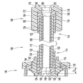
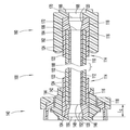
도 4를 참조하면, 커넥터 부재(140)의 수용 캐비티(144)에 조립되고 그 내부에 용매 결합된 억지 끼워맞춤 연결에 의해 고정된 튜브 단부(104) 및 오버몰딩된 단부 부재(114)를 구비한 커넥터 부재(140)의 유한 요소 해석(FEA) 도표가 도시되어 있다. 도 4에서, 커넥터 부재(140)의 커넥터 허브(142)의 FEA 도표는, 일단 복합 튜브 단부(104) 및 오버몰딩된 단부 부재(114)가 커넥터 부재(140)의 수용 캐비티(144) 내에 안착 및 고정되었을 때, 커넥터 허브(142)에서의 응력 집중(S) 위치를 보여준다. 응력 집중(S) 위치는, 커넥터 허브(142)의 수용 캐비티(144)에서 축방향 길이(L1)를 따라 미리 선택된 축방향 위치들에서 위치될 본 개시물에 따른 커넥터 허브(142)를 따라 축방향으로 변경될 수 있다. 이러한 축방향 위치는 미리 선택되거나 "미리 제어"되어, 축방향 길이(L1)를 따른 실질적으로 임의의 원하는 위치에서, 일반적으로는 응력 상승부, 예컨대 단단한 계면, 코너, 에지, 날카롭거나 돌출된 표면 특징부 또는 재료가 얇은 부위로부터 떨어진 위치들에서 응력 집중(S) 부위를 위치시킬 수 있다. 이러한 방식으로, 커넥터 허브(142)에서의 응력 집중(S)은 미리 선택되거나 "미리 제어"된 축방향 위치에 설정될 수 있고, 따라 커넥터 부재(140)에서의 응력 집중은 사전에 "미리 제어"될 수 있다. 이러한 응력 집중(S)은, 튜브 단부(104) 및 오버몰딩된 단부 부재(114)가 수용 캐비티(144)에 조립되고 튜브 부재(102)가 반복해서 가압될 때, 커넥터 허브(142)에 미세 균열 및 크랙 형성을 유발할 수 있다. 본 발명은, 응력 집중(S) 위치를 미리 선택하거나 또는 "미리 제어"함으로써 커넥터 허브(142)를 따라 미리 선택된 축방향 위치에 위치시켜, 단단한 계면, 코너, 에지, 날카롭거나 돌출된 표면 특징부 또는 재료가 얇은 부위들에서 응력 상승부를 피하고, 더욱 "편평한" 표면 특징부를 가지며 상술한 응력-유도 특징부들이 대체로 없는 커넥터 허브(142)를 따른 축방향 위치들에 위치되도록 할 수 있는, 방법 및 물리적 구성을 제공한다.Referring to Figure 4, a
도 5에는, 커넥터 부재(140)의 수용 캐비티(140)에 안착 및 고정된 오버몰딩된 단부 부재(114)를 보여주는 오버몰딩된 단부 부재(114)의 FEA 도표가 제공된다. 도 5는 내측의 튜브 부재(102)가 대략 1200 psi의 압력 하에 있을 때 단부 부재(114)에서의 응력 집중(S)을 보여준다. 단부 부재(114)에서의 응력 집중(S)은, 튜브 단부(104)가 단부 부재(114) 내부에 안착되어 끼워맞춤된 위치에서 대체로 가장 두드러지거나 또는 최대이다. 도 5에서, 튜브 부재(102)가 압력을 받을 때, 압력은 커넥터 부재(140)의 커넥터 허브(142) 내부에서 튜브 단부(104) 상의 튜브 부재(102) 및 오버몰딩된 단부 부재(114)를 신장시킨다. 튜브 단부(104)는 압력을 받으면서도 커넥터 허브(142)의 몸체 내부(예컨대, 수용 캐비티(144) 내부)에 유지되어 파열을 방지해야 하며, 이러한 위치 설정은, 오버몰딩된 단부 부재(114)의 내부에서 튜브 단부(104)의 축방향 위치 설정을 미리 선택하거나 또는 "미리 제어"함으로써, 그리고 오버몰딩된 단부 부재(114)를 형성하는 재료의 경도를 미리 선택함으로써 달성된다.5, there is provided an FEA chart of an
도 4 및 도 5를 함께 참고하여 전반적으로 알 수 있는 바와 같이, 오버몰딩된 단부 부재(114)에서의 응력 집중(S)은, 수용 캐비티(144) 내에 조립되어 압력을 받을 때, 커넥터 부재(140)의 커넥터 허브(142)에서의 응력 집중(S)과 대략 반경방향으로 동일한 공간에 걸쳐 있다. 따라서, 오버몰딩된 단부 부재(114)에서의 응력 집중(S) 위치를 미리 선택하거나 또는 "미리 제어"하는 것은, 마찬가지로 커넥터 허브(142)에서의 응력 집중(S) 위치를 미리 선택하거나 또는 "미리 제어"하며, 이러한 위치는 대체로 오버몰딩된 단부 부재(114) 내부에서의 튜브 단부(104)의 축방향 위치 설정에 좌우된다. 전술한 바와 같이, 커넥터 허브(142)에서의 응력 집중(S)의 위치를 미리 선택하거나 또는 "미리 제어"하여 이러한 미리 선택되거나 "미리 제어"된 위치가 단단한 계면, 코너, 에지, 날카롭거나 돌출된 표면 특징부, 또는 재료가 얇은 부위에서 응력 상승부를 피하고, 대안적으로는 "편평한" 표면 특징부를 가지고 상술한 응력-유도 특징부가 대체로 없는 커넥터 허브(142)를 따른 축방향 위치들에 위치되도록 하는 것이 바람직하다.4 and 5, the stress concentration S at the
도 6 내지 도 8은, 오버몰딩된 단부 부재(114) 내부의 상이한 축방향 위치들에 튜브 단부(104)가 위치됨으로써, 오버몰딩된 단부 부재(114)의 응력 집중(S)의 축방향 위치를 변화시키고 그에 따라 오버몰딩된 단부 부재(114)로부터 반경방향 외측으로 위치된 커넥터 허브(142)에서의 응력 집중(S)의 축방향 위치를 변화시키는, 커넥터 배관(100)의 세 가지 예시적인 실시예를 도시한다. 도 6 내지 도 8을 차례로 참조하여 알 수 있는 바와 같이, 오버몰딩된 단부 부재(114) 내부에서 튜브 단부(104)의 축방향 위치는, 단부 부재(114)의 관형 몸체(116)의 끝단 부분(118)의 축방향 길이(L2)를 줄이거나 늘임으로써 변화된다. 도 6 내지 도 8에서, 커넥터 부재(140, 160)의 구성은 다양할 수 있음을 이해할 것이며, 도 2 및 도 6 내지 도 8에서 커넥터 부재(140, 160)의 설명은 단지 예시적인 것으로 의도된다. 도 6은 가장 짧은 축방향 길이(L2)를 가진 끝단 부분(118)을 보여주며, 그에 따라 단부 부재(114) 내부에서 튜브 단부(104)의 축방향 위치가 세 가지 예 중에서 커넥터 포트(146)의 유체 통로(148)에 가장 가깝다. 따라서, 도 6에서 커넥터 허브(142)에서의 반경방향 응력 집중은 세 가지 예 중에서 커넥터 포트(146)에 가장 가깝다. 도 7은 약간 더 긴 축방향 길이(L2)를 가진 끝단 부분(118)을 보여주고, 그에 따라 단부 부재(114) 내부에서 튜브 단부(104)의 축방향 위치는 커넥터 포트(146)의 유체 통로(148)로부터 조금 더 멀리 이격된다. 따라서, 도 7에서 커넥터 허브(142)에서의 반경방향 응력 집중은 이제 세 가지 예 중에서 커넥터 포트(146)로부터 더 멀리 떨어지게 된다. 도 8은 훨씬 더 긴 축방향 길이(L2)를 가진 끝단 부분(118)을 보여주고, 그에 따라 오버몰딩된 단부 부재(114) 내부에서 튜브 단부(104)의 축방향 위치는, 존재하는 세 가지 예 중에서 커넥터 포트(146)의 유체 통로(148)로부터 훨씬 더 멀리 이격된다. 따라서, 도 8에서 커넥터 허브(142)에서의 반경방향 응력 집중은 이제 세 가지 예 중에서 커넥터 포트(146)로부터 가장 멀리 떨어지게 된다. 오버몰딩된 단부 부재(114) 내부에서의 튜브 단부(104)의 축방향 위치를 변경(단부 부재(114)의 관형 몸체(116)의 끝단 부분(118)의 축방향 길이(L2)를 줄이거나 늘임으로써 달성될 수 있음)함으로써, 커넥터 허브(142)에서의 응력 집중은, 수용 캐비티(144)의 축방향 길이(L1)를 따라 축방향으로 이동될 수 있고, 이에 따라 커넥터 허브(142)의 축방향 길이를 따라 축방향으로 이동될 수 있다. 따라서, 커넥터 허브(142)에서의 응력 집중의 위치는 미리 선택되거나 또는 "미리 제어"되어, 단단한 계면, 코너, 에지, 날카롭거나 돌출된 표면 특징부, 또는 재료가 얇은 부위에서 응력 상승부를 피하고, 대안적으로는 바람직하게 "편평한" 표면 특징부를 가지고 상술한 응력-유도 특징부가 대체로 없는 커넥터 허브(142)를 따른 축방향 위치들에 미리 선택되거나 "미리 제어"된다. 상술한 논의는 커넥터 부재(140)를 참조로 하지만, 상술한 논의를 커넥터 부재(160) 또는 의료 분야에 공지된 어떠한 적합한 루어 커넥터 부재 또는 허브에도 동일하게 적용 가능하다. 본 발명은 튜브 단부(104, 106) 상에서 오버몰딩된 부재(114)의 끝단 부분(118)의 축방향 길이를 조정함으로써, 의료용 커넥터 부재에서의 반경방향 응력 집중 위치를 미리 선택되거나 "미리 제어"될 수 있게 한다.Figures 6-8 show that the
고압 의료용 커넥터 배관 조립체 및 그 구성요소 또는 부재의 몇 가지 실시예를 첨부 도면에 도시하고 위에서 상세히 절명하였지만, 본 발명의 범주 및 사상을 벗어나지 않는 범위 내에서 기타 다른 실시예들이 당업자에게 명확하며 용이하게 만들어질 것이다. 따라서, 상술한 설명은 제한적이기보다는 예시적인 것으로 의도된다. 상술된 발명은 첨부된 청구항에 의해 정의되며, 청구항의 등가물의 의미 및 범위 내에 속하는 본 발명의 모든 변경은 청구항의 범주 내에 포괄되는 것이다.Although several embodiments of the high-pressure medical connector tubing assembly and its components or members are shown in the accompanying drawings and described above in detail, other embodiments will be apparent to those skilled in the art without departing from the scope and spirit of the invention. Will be created. Accordingly, the above description is intended to be illustrative, rather than restrictive. The foregoing invention is defined by the appended claims, and all changes which come within the meaning and range of equivalency of the claims are to be embraced within their scope of the claims.
Claims (20)
상기 서로 반대측의 튜브 단부들 중 적어도 하나에 오버몰딩되며, 미리 선택된 길이를 가지는 환형 끝단 부분을 포함하는 단부 부재; 및
수용 캐비티를 정의하는 커넥터 허브를 포함하는 커넥터 부재로서, 상기 오버몰딩된 단부 부재를 구비한 상기 튜브 단부가 상기 수용 캐비티에 고정되는 것인 커넥터 부재를 포함하되,
상기 환형 끝단 부분의 상기 미리 선택된 길이는 상기 커넥터 허브에서 응력이 집중되는 축방향 위치를 미리 제어하는 것인, 고압 의료용 커넥터 배관 조립체.A tube member including opposite tube ends and passages;
An end member overmolded onto at least one of said opposite tube ends and including an annular end portion having a preselected length; And
A connector member comprising a connector hub defining a receiving cavity, wherein the tube end with the overmolded end member is secured to the receiving cavity,
Wherein the pre-selected length of the annular end portion pre-controls an axial position at which stress is concentrated in the connector hub.
상기 오버몰딩된 단부 부재를 구비한 상기 튜브 단부는 용매 결합에 의해 상기 수용 캐비티에 고정되는 것인, 고압 의료용 커넥터 배관 조립체.The method according to claim 1,
Wherein the tube end with the overmolded end member is secured to the receiving cavity by solvent bonding.
상기 오버몰딩된 단부 부재를 구비한 상기 튜브 단부가 상기 수용 캐비티에 삽입되는 깊이를 시각적으로 확인하기 위해, 상기 단부 부재에는 적어도 하나의 외측 표시기가 형성되는 것인, 고압 의료용 커넥터 배관 조립체.The method according to claim 1,
Wherein at least one outer indicator is formed in the end member to visually identify the depth at which the tube end with the overmolded end member is inserted into the receiving cavity.
상기 튜브 부재는, 가요성 폴리머층으로 캡슐화된 내부 브레이드로 형성된 브레이드 배관을 포함하는 것인, 고압 의료용 커넥터 배관 조립체.The method according to claim 1,
Wherein the tubular member comprises a braid tubing formed of an inner braid encapsulated with a flexible polymer layer.
상기 커넥터 부재는 유체 통로를 정의하는 커넥터 포트를 포함하는 것인, 고압 의료용 커넥터 배관 조립체.The method according to claim 1,
Wherein the connector member includes a connector port defining a fluid passageway.
상기 환형 끝단 부분은, 상기 유체 통로로부터 상기 튜브 부재의 통로까지 테이퍼지는 테이퍼 입구를 정의하는 것인, 고압 의료용 커넥터 배관 조립체.6. The method of claim 5,
The annular end portion defining a tapered inlet that tapers from the fluid passageway to the passage of the tube member.
상기 입구는 대략 0° 내지 80°의 각도로 테이퍼지는 것인, 고압 의료용 커넥터 배관 조립체.The method according to claim 6,
The inlet tapering at an angle of approximately 0 ° to 80 °.
상기 튜브 부재의 상기 튜브 단부 각각에 단부 부재가 오버몰딩되는 것인, 고압 의료용 커넥터 배관 조립체.The method according to claim 1,
Wherein an end member is overmolded at each of the tube ends of the tube member.
상기 커넥터 부재는 한 쌍의 커넥터 부재를 포함하며, 오버몰딩된 단부 부재를 각각 갖는 상기 튜브 단부들은 상기 커넥터 부재들의 상기 수용 캐비티들에 각각 고정된 것인, 고압 의료용 커넥터 배관 조립체.In the eighth aspect,
Wherein the connector member includes a pair of connector members and the tube ends each having an overmolded end member are each secured to the receiving cavities of the connector members.
상기 튜브 부재는, 가요성 폴리머층으로 캡슐화된 내부 브레이드로 형성된 브레이드 배관을 포함하는 것인, 고압 의료용 커넥터 배관 조립체.9. The method of claim 8,
Wherein the tubular member comprises a braid tubing formed of an inner braid encapsulated with a flexible polymer layer.
상기 서로 반대측의 튜브 단부들 중 적어도 하나에, 미리 선택된 길이를 갖는 환형 끝단 부분을 포함하는 단부 부재를 오버몰딩하는 단계;
수용 캐비티를 정의하는 커넥터 허브를 포함하는 커넥터 부재를 제공하는 단계; 및
상기 오버몰딩된 단부 부재를 구비한 상기 튜브 단부를 상기 수용 캐비티에 고정하는 단계를 포함하되,
상기 환형 끝단 부분의 상기 미리 선택된 길이는 상기 커넥터 허브에서 응력이 집중되는 축방향 위치를 미리 제어하는 것인, 고압 의료용 커넥터 배관 조립체의 형성 방법.Providing a tube member comprising opposite tube ends and passages;
Overmolding at least one of the opposite tube ends with an end member comprising an annular end portion having a preselected length;
Providing a connector member including a connector hub defining an accommodation cavity; And
Securing the tube end with the overmolded end member to the receiving cavity,
Wherein the preselected length of the annular end portion pre-controls an axial position at which stress is concentrated in the connector hub. ≪ Desc / Clms Page number 19 >
상기 오버몰딩된 단부 부재를 구비한 상기 튜브 단부를 상기 수용 캐비티에 고정하는 단계는 용매 결합을 포함하는 것인 방법.12. The method of claim 11,
Wherein the step of securing the tube end with the overmolded end member to the receiving cavity comprises solvent bonding.
상기 오버몰딩된 단부 부재를 구비한 상기 튜브 단부가 상기 수용 캐비티에 삽입되는 깊이를 시각적으로 확인하기 위해, 상기 단부 부재에는 적어도 하나의 외측 표시기가 형성되는 것인 방법.12. The method of claim 11,
Wherein at least one outer indicator is formed in the end member to visually identify the depth at which the tube end with the overmolded end member is inserted into the receiving cavity.
상기 튜브 부재는, 가요성 폴리머층으로 캡슐화된 내부 브레이드로 형성된 브레이드 배관을 포함하는 것인 방법.12. The method of claim 11,
Wherein the tubular member comprises a braid tubing formed of an inner braid encapsulated with a flexible polymer layer.
상기 커넥터 부재는 유체 통로를 정의하는 커넥터 포트를 포함하는 것인 방법.12. The method of claim 11,
Wherein the connector member includes a connector port defining a fluid passage.
상기 환형 끝단 부분은, 상기 유체 통로로부터 상기 튜브 부재의 통로까지 테이퍼지는 테이퍼 입구를 정의하는 것인 방법.16. The method of claim 15,
The annular end portion defining a tapered inlet that tapers from the fluid passage to the passage of the tube member.
상기 입구는 대략 0° 내지 80°의 각도로 테이퍼지는 것인 방법.17. The method of claim 16,
Wherein said inlet is tapered at an angle of approximately 0 ° to 80 °.
상기 튜브 부재의 상기 튜브 단부들 각각에 단부 부재를 오버몰딩하는 단계를 더 포함하는 방법.12. The method of claim 11,
Further comprising overmolding an end member at each of the tube ends of the tube member.
오버몰딩된 단부 부재를 각각 갖는 상기 튜브 단부들은 상기 커넥터 부재의 상기 수용 캐비티에 각각 고정된 것인 방법.18. The method of claim 18,
Wherein the tube ends each having an overmolded end member are each secured to the receiving cavity of the connector member.
상기 튜브 부재는, 가요성 폴리머층으로 캡슐화된 내부 브레이드로 형성된 브레이드 배관을 포함하는 것인 방법.19. The method of claim 18,
Wherein the tubular member comprises a braid tubing formed of an inner braid encapsulated with a flexible polymer layer.
Applications Claiming Priority (3)
| Application Number | Priority Date | Filing Date | Title |
|---|---|---|---|
| US13/632,598 | 2012-10-01 | ||
| US13/632,598 US9901725B2 (en) | 2012-10-01 | 2012-10-01 | Overmolded medical connector tubing and method |
| PCT/US2013/061275 WO2014055283A1 (en) | 2012-10-01 | 2013-09-24 | Overmolded medical connector tubing and method |
Publications (1)
| Publication Number | Publication Date |
|---|---|
| KR20150064086A true KR20150064086A (en) | 2015-06-10 |
Family
ID=50384469
Family Applications (1)
| Application Number | Title | Priority Date | Filing Date |
|---|---|---|---|
| KR1020157009718A KR20150064086A (en) | 2012-10-01 | 2013-09-24 | Overmolded medical connector tubing and method |
Country Status (12)
| Country | Link |
|---|---|
| US (1) | US9901725B2 (en) |
| EP (1) | EP2903682B1 (en) |
| JP (2) | JP6346613B2 (en) |
| KR (1) | KR20150064086A (en) |
| CN (1) | CN104755131B (en) |
| AU (1) | AU2013327687B2 (en) |
| BR (1) | BR112015007292A2 (en) |
| CA (1) | CA2885732A1 (en) |
| HK (1) | HK1211880A1 (en) |
| IN (1) | IN2015DN02338A (en) |
| RU (1) | RU2649471C2 (en) |
| WO (1) | WO2014055283A1 (en) |
Families Citing this family (18)
| Publication number | Priority date | Publication date | Assignee | Title |
|---|---|---|---|---|
| EP3038812B1 (en) * | 2013-08-29 | 2019-11-20 | Alphinity, LLC | Method and device for overmolding uv-curable material over polymer inserts |
| US8803844B1 (en) * | 2013-10-02 | 2014-08-12 | DigiPuppets LLC | Capacitive finger puppet for use on touchscreen devices |
| TW201619539A (en) | 2014-11-21 | 2016-06-01 | 聖高拜塑膠製品公司 | Fluid transfer assembly |
| EP3240521A4 (en) * | 2014-12-31 | 2018-12-05 | Saint-Gobain Performance Plastics Corporation | Molded fluid transfer assemblies having increased working pressures and burst pressures |
| CN112107904B (en) * | 2015-03-20 | 2022-11-04 | 美国圣戈班性能塑料公司 | Connectionless filter capsule device |
| US10309556B2 (en) | 2015-04-17 | 2019-06-04 | Saint-Gobain Performance Plastics Corporation | Sterile port connection |
| WO2016168754A1 (en) * | 2015-04-17 | 2016-10-20 | Meissner Filtration Products, Inc. | Modular molding |
| US10195411B2 (en) * | 2015-07-16 | 2019-02-05 | Fresenius Medical Care Holdings, Inc. | Blood line sets with deformable blood lines |
| US10330228B2 (en) * | 2015-08-31 | 2019-06-25 | Ingersoll-Rand Company | Pipe connection fitting |
| GB201518888D0 (en) * | 2015-10-24 | 2015-12-09 | Smiths Medical Int Ltd | Medico-surgical tubes and their manufacture |
| US10653980B2 (en) | 2016-03-21 | 2020-05-19 | Saint-Gobain Performance Plastics Corporation | Connection-free filter capsule apparatus |
| EP3246052A1 (en) * | 2016-05-20 | 2017-11-22 | Fresenius Medical Care | Tube connection |
| WO2018187386A2 (en) * | 2017-04-03 | 2018-10-11 | Saint-Gobain Performance Plastics Corporation | Connection-free filter capsule apparatus |
| WO2019018489A1 (en) | 2017-07-19 | 2019-01-24 | Battelle Energy Alliance, Llc | A three-dimensional architectured anode, a direct carbon fuel cell including the three-dimensional architectured anode, and related methods |
| EP4106857A1 (en) | 2020-02-21 | 2022-12-28 | Bayer HealthCare, LLC | Fluid path connectors for medical fluid delivery |
| CN113578614A (en) * | 2020-04-30 | 2021-11-02 | 四川蓝光英诺生物科技股份有限公司 | Body duct repairing device and method of operating body duct repairing device |
| AU2021292515A1 (en) | 2020-06-18 | 2022-12-22 | Bayer Healthcare Llc | In-line air bubble suspension apparatus for angiography injector fluid paths |
| EP4144404B1 (en) | 2021-09-06 | 2024-04-10 | BIOTRONIK SE & Co. KG | Electrode tip for an implantable cardiac electrode |
Family Cites Families (123)
| Publication number | Priority date | Publication date | Assignee | Title |
|---|---|---|---|---|
| US1799463A (en) | 1926-03-19 | 1931-04-07 | George N Hein | Hypodermic syringe |
| US1718474A (en) | 1926-08-09 | 1929-06-25 | John W Mcquaid | Piston |
| US1850273A (en) | 1927-04-02 | 1932-03-22 | Robert W Thayer | Transfusion apparatus |
| US1748810A (en) | 1928-02-09 | 1930-02-25 | Wandel Barney | Syringe |
| US2052616A (en) | 1932-12-27 | 1936-09-01 | Ncr Co | Key and method of manufacturing the same |
| US2578394A (en) | 1947-12-04 | 1951-12-11 | Premo Pharmaceutical Lab Inc | Hypodermic syringe |
| US2602447A (en) | 1947-12-20 | 1952-07-08 | Kollsman Paul | Device for hypodermic injection |
| US2592381A (en) | 1949-10-13 | 1952-04-08 | Premo Pharmaceutical Lab Inc | Hypodermic syringe |
| US2607342A (en) | 1950-11-24 | 1952-08-19 | Martin S Abel | Syringe |
| US3176595A (en) | 1963-05-22 | 1965-04-06 | Galland Henning Mfg Company | Plastic piston assembly |
| US3354882A (en) | 1964-10-26 | 1967-11-28 | Pharmaseal Lab | Hypodermic syringe |
| DE1491861C3 (en) | 1966-07-05 | 1975-07-10 | Veb Kombinat Medizin- Und Labortechnik Leipzig, X 7035 Leipzig | Injection syringe for medical devices |
| US3577850A (en) | 1968-09-26 | 1971-05-11 | Precision Sampling Corp | Method of forming seals |
| US3981956A (en) | 1972-04-07 | 1976-09-21 | Abbott Laboratories | Continuous automated plastic molding method |
| US3892512A (en) | 1973-09-13 | 1975-07-01 | Alan V Diehl | Transfer molding apparatus with resilient pad to distribute molding pressure |
| US4398989A (en) | 1974-05-24 | 1983-08-16 | The West Company | System for making molded articles |
| US3985133A (en) | 1974-05-28 | 1976-10-12 | Imed Corporation | IV pump |
| US4076285A (en) | 1975-08-01 | 1978-02-28 | Erika, Inc. | Laminar flow connector for conduits |
| US4044765A (en) * | 1975-12-17 | 1977-08-30 | Medical Evaluation Devices And Instruments Corporation | Flexible tube for intra-venous feeding |
| US4044757A (en) | 1976-01-14 | 1977-08-30 | The Kendall Company | Cholangiography device and method |
| US4074715A (en) | 1976-11-01 | 1978-02-21 | Becton, Dickinson And Company | Syringe plunger |
| US4089335A (en) | 1976-11-11 | 1978-05-16 | Harris Rano J | Microsyringe |
| US4214507A (en) | 1977-08-24 | 1980-07-29 | Vries Donald S Jr De | One-piece plastic piston |
| US4184836A (en) | 1978-01-27 | 1980-01-22 | Husky Injection Molding Systems Ltd. | Multiple mold for producing elongate tubular articles |
| US4201209A (en) | 1978-05-24 | 1980-05-06 | Leveen Harry H | Molded hypodermic plunger with integral shaft and elastomeric head |
| US4450079A (en) | 1979-09-06 | 1984-05-22 | Imed Corporation | Cassette for providing a controlled flow of fluid |
| US4385025A (en) | 1979-10-22 | 1983-05-24 | Barry Wright Corporation | Method of coinjection molding of thermoplastic and thermoplastic elastomer |
| US4389271A (en) | 1980-06-05 | 1983-06-21 | The West Company | Method for making molded articles |
| US4381275A (en) | 1981-01-30 | 1983-04-26 | Trade Finance International | Stabilized core injection molding of plastic |
| JPS5886173A (en) | 1981-11-16 | 1983-05-23 | 東洋製罐株式会社 | Gasket of container for blood transfusion and preparation thereof |
| US4431031A (en) * | 1982-03-29 | 1984-02-14 | Amco Corporation | Pre-rinse hose |
| US4485065A (en) | 1982-03-30 | 1984-11-27 | Yoshida Industry Co., Ltd. | Method for forming bottle closure |
| US4447229A (en) | 1982-03-31 | 1984-05-08 | Butterfield Group | Tamper-resistant hypodermic syringe |
| US4803031A (en) | 1982-06-03 | 1989-02-07 | Anchor Hocking Corporation | Method and apparatus for molding a closure cap |
| US4543093A (en) | 1982-12-20 | 1985-09-24 | Becton, Dickinson And Company | Variable sealing pressure plunger rod assembly |
| US4554125A (en) | 1983-03-17 | 1985-11-19 | Schering Corporation | Method of making a stopper for a sterile fluid container |
| US4585435A (en) * | 1984-05-31 | 1986-04-29 | The Telescope Folding Furniture Co., Inc. | Extension set for drug delivery |
| US4605396A (en) | 1985-02-25 | 1986-08-12 | Warner-Lambert Company | Gravity flow cassette with rotary valve |
| US4662868A (en) | 1985-07-26 | 1987-05-05 | University Of Pittsburgh | Syringe apparatus and valve employed therein |
| US4701165A (en) | 1986-03-26 | 1987-10-20 | Abbott Interfast Corp. | Reusable syringes |
| JPH0747045B2 (en) | 1986-10-15 | 1995-05-24 | 株式会社大協精工 | Stacked syringe stopper |
| DE8701394U1 (en) * | 1987-01-29 | 1988-05-26 | B. Braun Melsungen Ag, 3508 Melsungen, De | |
| EP0315586B1 (en) | 1987-10-31 | 1991-09-04 | Schöttli Ag | Hot runner channel injection mould for producing throw-away syringes and the like |
| US4850980A (en) | 1987-12-04 | 1989-07-25 | Fisher Scientific Company | I.V. pump cassette |
| US4957682A (en) | 1988-01-19 | 1990-09-18 | Kamaya Kagaku Kogyo Co., Ltd. | Method of injection molding a three-layered container |
| JPH0534669Y2 (en) | 1988-03-16 | 1993-09-02 | ||
| US5007904A (en) | 1989-01-19 | 1991-04-16 | Coeur Laboratories, Inc. | Plunger for power injector angiographic syringe, and syringe comprising same |
| DE3902943A1 (en) | 1989-02-01 | 1990-08-09 | Wolf Gmbh Richard | DEVICE FOR INPUTING AND EXTRACTING LIQUIDS IN OR FROM BODY HOLLOW ORGANS |
| WO1990010816A1 (en) | 1989-03-16 | 1990-09-20 | Shell Oil Company | Tubular coupling and method of forming same |
| US4986820A (en) | 1989-06-23 | 1991-01-22 | Ultradent Products, Inc. | Syringe apparatus having improved plunger |
| US5460625A (en) * | 1990-07-31 | 1995-10-24 | Baxter International Inc. | Cryogenic resistant coextruded tubing |
| US5279606A (en) | 1991-08-28 | 1994-01-18 | Habley Medical Technology Corporation | Non-reactive composite sealing barrier |
| US5314416A (en) | 1992-06-22 | 1994-05-24 | Sherwood Medical Company | Low friction syring assembly |
| JP3345147B2 (en) * | 1993-01-26 | 2002-11-18 | テルモ株式会社 | Vasodilators and catheters |
| US5314415A (en) | 1993-07-21 | 1994-05-24 | Sterling Winthrop Inc. | Aspirating plunger for power injector cartridges |
| US5377689A (en) | 1993-12-27 | 1995-01-03 | Mercereau; Steven F. | Sampling syringe |
| US5484566A (en) | 1994-03-07 | 1996-01-16 | Wheaton Inc. | Method of manufacture of a partially laminated rubber closure |
| EP0688652B1 (en) | 1994-06-06 | 2000-06-14 | Husky Injection Molding Systems Ltd. | Opposed gating injection method |
| US5830184A (en) | 1996-03-06 | 1998-11-03 | Medical Components, Inc. | Composite catheter stabilizing devices, methods of making the same and catheter extracting device |
| US5902276A (en) | 1996-11-26 | 1999-05-11 | Liebel-Flarsheim Company | Two-shot molded plunger |
| DE29701861U1 (en) | 1997-02-04 | 1998-06-10 | Fresenius Ag | Device for dosing medical liquids |
| US6720044B2 (en) | 1997-02-20 | 2004-04-13 | Pharmacia Ab | Polyolefinic closures comprising penetrable plugs and annular channels |
| JP3387775B2 (en) | 1997-05-22 | 2003-03-17 | 株式会社大協精工 | Sealing stopper for syringe and prefilled syringe |
| US6004300A (en) | 1997-08-28 | 1999-12-21 | Butcher; Robert M | Composite hypodermic syringe piston |
| GB2333458A (en) | 1998-01-27 | 1999-07-28 | Marconi Gec Ltd | Injection system for pre-polarised fluid used in magnetic resonance (MR) measurements |
| US6165402A (en) | 1998-01-30 | 2000-12-26 | Abbott Laboratories | Method for making a stopper |
| JP3807871B2 (en) | 1998-05-28 | 2006-08-09 | 株式会社ニデック | Laser therapy device |
| US6817990B2 (en) | 1998-10-29 | 2004-11-16 | Medtronic Minimed, Inc. | Fluid reservoir piston |
| JP3142521B2 (en) | 1998-11-04 | 2001-03-07 | 大成プラス株式会社 | Needlestick stopcock and its manufacturing method |
| EP1099449A1 (en) | 1999-11-12 | 2001-05-16 | Schöttli Ag | Plunger for a single use syringe and method of manufacture thereof |
| DE10006560A1 (en) | 2000-02-15 | 2001-08-23 | Disetronic Licensing Ag | Two-component piston stopper |
| JP2001299906A (en) * | 2000-04-25 | 2001-10-30 | Terumo Corp | Connector assembly |
| US20030039717A1 (en) | 2000-05-01 | 2003-02-27 | Hwang C. Robin | Injection molding of thermoplastic parts |
| US20030030186A1 (en) | 2000-05-01 | 2003-02-13 | Riiska Matthew T. | Sprueless hydrostatic injection molding |
| JP2001333980A (en) | 2000-05-26 | 2001-12-04 | Ookisu:Kk | Continuous liquid medicine injector |
| JP2002089717A (en) | 2000-09-14 | 2002-03-27 | Terumo Corp | Gasket |
| US6912423B2 (en) | 2000-12-15 | 2005-06-28 | Cardiac Pacemakers, Inc. | Terminal connector assembly for a medical device and method therefor |
| US6494866B1 (en) | 2001-04-05 | 2002-12-17 | Owens-Illinois Closure Inc. | Syringe plunger rod and method of manufacture |
| US6974447B2 (en) | 2001-04-17 | 2005-12-13 | Baxter International Inc. | High gas barrier receptacle and closure assembly |
| DE10122959A1 (en) | 2001-05-11 | 2002-11-21 | West Pharm Serv Drug Res Ltd | Method for producing a piston for a pharmaceutical syringe or a similar item includes a step in which surplus of the inert foil cap on the piston body is separated in a punching unit |
| EP1405708A4 (en) | 2001-07-03 | 2007-09-05 | Top Kk | Method of manufacturing outer tube of injector |
| DE10144892B4 (en) | 2001-09-12 | 2005-09-08 | Disetronic Licensing Ag | Multilayer plastic body |
| US6758836B2 (en) | 2002-02-07 | 2004-07-06 | C. R. Bard, Inc. | Split tip dialysis catheter |
| DE10226643A1 (en) | 2002-06-14 | 2004-01-15 | Disetronic Licensing Ag | Piston stopper for injection device, product container and injection device |
| US6902210B1 (en) | 2002-11-01 | 2005-06-07 | William W. Rowley | Universal connector tubing |
| US20040100093A1 (en) | 2002-11-21 | 2004-05-27 | Leigh-Monstevens Keith V. | Co-extruded tube with molded connector |
| JP4288957B2 (en) | 2003-02-24 | 2009-07-01 | 株式会社ジェイ・エム・エス | Tube connection tube for extracorporeal circulation |
| US20100145313A1 (en) * | 2003-04-04 | 2010-06-10 | Packard Brian M | System and method for treating septal defects |
| US20050048640A1 (en) | 2003-08-25 | 2005-03-03 | Gen-Probe Incorporated | Clamp and method of making same |
| EP1670523B1 (en) | 2003-10-08 | 2018-10-03 | Medical Components, Inc. | Co-axial tapered catheter |
| US8382739B2 (en) * | 2003-12-02 | 2013-02-26 | Boston Scientific Scimed, Inc. | Composite medical device and method of forming |
| US7491191B2 (en) | 2004-02-13 | 2009-02-17 | Liebel-Flarsheim Company | Keep vein open method and injector with keep vein open function |
| JP2007532181A (en) | 2004-04-08 | 2007-11-15 | イーライ リリー アンド カンパニー | Drug cartridge piston with rigid core |
| US7166089B2 (en) | 2004-04-22 | 2007-01-23 | Ping Te Huang | Plunger of a syringe |
| IL161660A0 (en) | 2004-04-29 | 2004-09-27 | Medimop Medical Projects Ltd | Liquid drug delivery device |
| US20060069356A1 (en) | 2004-08-24 | 2006-03-30 | Norbert Witowski | Plunger for a syringe and syringe |
| FR2876601B1 (en) | 2004-10-19 | 2006-12-29 | Claude Jaunay | SECURING METHOD, MANUFACTURING METHOD, AND SECURE SPRAY TIP |
| US20060170134A1 (en) | 2005-01-28 | 2006-08-03 | Rowley William W | Process for over-molding onto crosslinked polymers |
| JP4830501B2 (en) | 2005-02-21 | 2011-12-07 | オムロン株式会社 | Substrate inspection method and apparatus, and inspection logic setting method and apparatus thereof |
| US20070073223A1 (en) | 2005-07-06 | 2007-03-29 | Hung-Chi Huang | Push rod of a syringe |
| US7749202B2 (en) | 2005-08-29 | 2010-07-06 | West Pharmaceutical Services, Inc. | Dual material plunger tip for use with a syringe |
| WO2007092226A2 (en) | 2006-02-02 | 2007-08-16 | Cooper-Standard Automotive Inc. | Reinforced plastic hose |
| WO2007137184A2 (en) | 2006-05-18 | 2007-11-29 | Applied Medical Resources Corporation | Method of making medical tubing having variable characteristics using thermal winding |
| WO2008033922A2 (en) | 2006-09-12 | 2008-03-20 | Neochild, Llc | Fluid delivery device |
| US8257286B2 (en) * | 2006-09-21 | 2012-09-04 | Tyco Healthcare Group Lp | Safety connector apparatus |
| WO2008070220A1 (en) | 2006-12-05 | 2008-06-12 | Caridianbct, Inc. | Connector system for sterile connection |
| RU2419409C2 (en) * | 2006-12-25 | 2011-05-27 | Меккель-Шпенглерзан Гмбх | Syringe adaptor for reliable connection of syringes with different designs |
| US20080178957A1 (en) | 2007-01-31 | 2008-07-31 | Masco Corporation Of Indiana | Tube assembly |
| WO2008144513A1 (en) | 2007-05-18 | 2008-11-27 | Optiscan Biomedical Corporation | Low-volume fittings |
| CN102652857B (en) * | 2007-06-08 | 2014-08-20 | 株式会社Jms | Female connector and connector |
| US7618276B2 (en) | 2007-06-20 | 2009-11-17 | Amphenol Corporation | Connector assembly with gripping sleeve |
| CA2646261A1 (en) | 2007-12-14 | 2009-06-14 | Tyco Healthcare Group Lp | Blood collection device with tube retaining structure |
| US8251346B2 (en) | 2008-03-04 | 2012-08-28 | Infusion Innovations, Inc. | Devices, assemblies, and methods for controlling fluid flow |
| EP2158935B1 (en) | 2008-08-29 | 2014-07-16 | Dräger Medical GmbH | Connector for medicinal tubes |
| US8551074B2 (en) | 2008-09-08 | 2013-10-08 | Bayer Pharma AG | Connector system having a compressible sealing element and a flared fluid path element |
| US8080001B2 (en) | 2008-11-26 | 2011-12-20 | Acist Medical Systems, Inc. | Fluid connection assembly with locking mechanism |
| EP2422837B1 (en) | 2009-04-23 | 2014-12-24 | JMS Co., Ltd. | Medical connector structure |
| US8277714B1 (en) | 2009-11-13 | 2012-10-02 | Mercury Plastics, Inc. | Braid capture overmolding |
| US20110127186A1 (en) | 2009-11-27 | 2011-06-02 | Enns Thomas Frederick | Package for Elongate Medical Devices |
| US20110306826A1 (en) | 2010-04-30 | 2011-12-15 | Allergan Inc. | Over molded implantable device to protect tubing from puncture |
| WO2012021596A1 (en) | 2010-08-10 | 2012-02-16 | Idex Health & Science Llc | Biocompatible tubing for liquid chromatography systems |
| US20120216903A1 (en) * | 2011-02-28 | 2012-08-30 | Flo-Link, LLC | Multi-layer tubing and method for joining |
| EP2514478B1 (en) | 2011-04-21 | 2013-07-31 | Plastiflex Group | Flexible plastic hose and method for manufacturing same |
-
2012
- 2012-10-01 US US13/632,598 patent/US9901725B2/en active Active
-
2013
- 2013-09-24 WO PCT/US2013/061275 patent/WO2014055283A1/en active Application Filing
- 2013-09-24 JP JP2015534589A patent/JP6346613B2/en active Active
- 2013-09-24 CN CN201380051367.XA patent/CN104755131B/en active Active
- 2013-09-24 CA CA2885732A patent/CA2885732A1/en active Pending
- 2013-09-24 KR KR1020157009718A patent/KR20150064086A/en not_active Application Discontinuation
- 2013-09-24 EP EP13844290.0A patent/EP2903682B1/en active Active
- 2013-09-24 IN IN2338DEN2015 patent/IN2015DN02338A/en unknown
- 2013-09-24 BR BR112015007292A patent/BR112015007292A2/en not_active IP Right Cessation
- 2013-09-24 RU RU2015116310A patent/RU2649471C2/en not_active IP Right Cessation
- 2013-09-24 AU AU2013327687A patent/AU2013327687B2/en active Active
-
2015
- 2015-12-23 HK HK15112616.2A patent/HK1211880A1/en not_active IP Right Cessation
-
2016
- 2016-10-13 JP JP2016201674A patent/JP2017035520A/en active Pending
Also Published As
| Publication number | Publication date |
|---|---|
| WO2014055283A1 (en) | 2014-04-10 |
| AU2013327687B2 (en) | 2018-10-25 |
| AU2013327687A1 (en) | 2015-04-09 |
| EP2903682A4 (en) | 2016-07-06 |
| CN104755131B (en) | 2017-10-13 |
| JP2017035520A (en) | 2017-02-16 |
| JP2015530191A (en) | 2015-10-15 |
| CN104755131A (en) | 2015-07-01 |
| CA2885732A1 (en) | 2014-04-10 |
| US9901725B2 (en) | 2018-02-27 |
| EP2903682A1 (en) | 2015-08-12 |
| JP6346613B2 (en) | 2018-06-20 |
| BR112015007292A2 (en) | 2017-07-04 |
| EP2903682B1 (en) | 2019-07-10 |
| RU2649471C2 (en) | 2018-04-03 |
| RU2015116310A (en) | 2016-11-27 |
| HK1211880A1 (en) | 2016-06-03 |
| IN2015DN02338A (en) | 2015-08-28 |
| US20140091569A1 (en) | 2014-04-03 |
Similar Documents
| Publication | Publication Date | Title |
|---|---|---|
| KR20150064086A (en) | Overmolded medical connector tubing and method | |
| US20230338724A1 (en) | Infusion tube system and method for manufacture | |
| EP3092030B1 (en) | Catheter devices with valves and related methods | |
| CN101983083B (en) | A medical connector | |
| EP2422837B1 (en) | Medical connector structure | |
| EP3283160B1 (en) | Modular molding | |
| CN103998090A (en) | Systems and methods for sealing a septum within a catheter device | |
| US20170336008A1 (en) | Tubing and junction assembly and method of making the same | |
| US20150137015A1 (en) | Connector for microfluidic device, a method for injecting fluid into microfluidic device using the connector and a method of providing and operating a valve | |
| CN108025166B (en) | Safety intravenous catheter with molded open blood control valve | |
| US9169950B2 (en) | Connector for flexible hoses | |
| JP2003325671A (en) | Introducer | |
| JP6922464B2 (en) | Connection structure of tubular members | |
| EP2799212B1 (en) | Method for assembling and sealing a reusable electrical surgical instrument | |
| CN111050710B (en) | Perfusion tube | |
| CN108744222B (en) | Hose line and method for producing the same | |
| JP7251430B2 (en) | medical braided tube assembly | |
| JP6933386B2 (en) | Indwelling needle | |
| JP3180838U (en) | Fitting pipe with sleeve | |
| WO2017159688A1 (en) | Balloon catheter, and method of producing long member for balloon catheter | |
| US20200001042A1 (en) | Catheter Elements for Bond-Strength Enhancement | |
| WO2013079961A1 (en) | Multitube catheter and method for making the same |
Legal Events
| Date | Code | Title | Description |
|---|---|---|---|
| N231 | Notification of change of applicant | ||
| WITN | Application deemed withdrawn, e.g. because no request for examination was filed or no examination fee was paid |