KR20150052837A - System and method for modular transportation of a welding system - Google Patents
System and method for modular transportation of a welding system Download PDFInfo
- Publication number
- KR20150052837A KR20150052837A KR1020157002782A KR20157002782A KR20150052837A KR 20150052837 A KR20150052837 A KR 20150052837A KR 1020157002782 A KR1020157002782 A KR 1020157002782A KR 20157002782 A KR20157002782 A KR 20157002782A KR 20150052837 A KR20150052837 A KR 20150052837A
- Authority
- KR
- South Korea
- Prior art keywords
- cylinder
- rail
- front panel
- rails
- panel
- Prior art date
Links
Images


Classifications
-
- B—PERFORMING OPERATIONS; TRANSPORTING
- B62—LAND VEHICLES FOR TRAVELLING OTHERWISE THAN ON RAILS
- B62B—HAND-PROPELLED VEHICLES, e.g. HAND CARTS OR PERAMBULATORS; SLEDGES
- B62B3/00—Hand carts having more than one axis carrying transport wheels; Steering devices therefor; Equipment therefor
- B62B3/10—Hand carts having more than one axis carrying transport wheels; Steering devices therefor; Equipment therefor characterised by supports specially adapted to objects of definite shape
-
- B—PERFORMING OPERATIONS; TRANSPORTING
- B23—MACHINE TOOLS; METAL-WORKING NOT OTHERWISE PROVIDED FOR
- B23P—METAL-WORKING NOT OTHERWISE PROVIDED FOR; COMBINED OPERATIONS; UNIVERSAL MACHINE TOOLS
- B23P19/00—Machines for simply fitting together or separating metal parts or objects, or metal and non-metal parts, whether or not involving some deformation; Tools or devices therefor so far as not provided for in other classes
-
- B—PERFORMING OPERATIONS; TRANSPORTING
- B62—LAND VEHICLES FOR TRAVELLING OTHERWISE THAN ON RAILS
- B62B—HAND-PROPELLED VEHICLES, e.g. HAND CARTS OR PERAMBULATORS; SLEDGES
- B62B3/00—Hand carts having more than one axis carrying transport wheels; Steering devices therefor; Equipment therefor
- B62B3/02—Hand carts having more than one axis carrying transport wheels; Steering devices therefor; Equipment therefor involving parts being adjustable, collapsible, attachable, detachable or convertible
-
- B—PERFORMING OPERATIONS; TRANSPORTING
- B62—LAND VEHICLES FOR TRAVELLING OTHERWISE THAN ON RAILS
- B62B—HAND-PROPELLED VEHICLES, e.g. HAND CARTS OR PERAMBULATORS; SLEDGES
- B62B2202/00—Indexing codes relating to type or characteristics of transported articles
- B62B2202/02—Cylindrically-shaped articles, e.g. drums, barrels, flasks
- B62B2202/022—Gas bottles
-
- B—PERFORMING OPERATIONS; TRANSPORTING
- B62—LAND VEHICLES FOR TRAVELLING OTHERWISE THAN ON RAILS
- B62B—HAND-PROPELLED VEHICLES, e.g. HAND CARTS OR PERAMBULATORS; SLEDGES
- B62B2202/00—Indexing codes relating to type or characteristics of transported articles
- B62B2202/48—Tools
-
- B—PERFORMING OPERATIONS; TRANSPORTING
- B62—LAND VEHICLES FOR TRAVELLING OTHERWISE THAN ON RAILS
- B62B—HAND-PROPELLED VEHICLES, e.g. HAND CARTS OR PERAMBULATORS; SLEDGES
- B62B2205/00—Hand-propelled vehicles or sledges being foldable or dismountable when not in use
- B62B2205/006—Hand-propelled vehicles or sledges being foldable or dismountable when not in use dismountable
-
- B—PERFORMING OPERATIONS; TRANSPORTING
- B62—LAND VEHICLES FOR TRAVELLING OTHERWISE THAN ON RAILS
- B62B—HAND-PROPELLED VEHICLES, e.g. HAND CARTS OR PERAMBULATORS; SLEDGES
- B62B2206/00—Adjustable or convertible hand-propelled vehicles or sledges
- B62B2206/02—Adjustable or convertible hand-propelled vehicles or sledges adjustable in length or width
-
- Y—GENERAL TAGGING OF NEW TECHNOLOGICAL DEVELOPMENTS; GENERAL TAGGING OF CROSS-SECTIONAL TECHNOLOGIES SPANNING OVER SEVERAL SECTIONS OF THE IPC; TECHNICAL SUBJECTS COVERED BY FORMER USPC CROSS-REFERENCE ART COLLECTIONS [XRACs] AND DIGESTS
- Y10—TECHNICAL SUBJECTS COVERED BY FORMER USPC
- Y10T—TECHNICAL SUBJECTS COVERED BY FORMER US CLASSIFICATION
- Y10T29/00—Metal working
- Y10T29/49—Method of mechanical manufacture
- Y10T29/49826—Assembling or joining
Abstract
본 실시예는 모듈형 용접 구성요소 운반 시스템(10)을 포함한다. 시스템은 전방 패널(12)과 휠 조립체(16)를 포함한다. 전방 패널은 용접 시스템 구성요소를 지지하도록 구성되는 지지 플랫폼을 포함하고 휠 조립체는 복수 개의 제1 휠을 포함한다. 시스템은 또한, 레일의 제1 단부에 근접한 전방 패널과 조절 가능하게 커플링하도록 구성되고 레일의 제2 단부에 근접한 휠 조립체와 커플링하도록 구성되는 레일(14)을 포함한다. 휠 조립체의 배치면은 휠 조립체의 벽과 결합하기 위해 레일을 수용하고 정렬시키도록 구성된다. 시스템은 전방 패널과 결합되거나 레일의 제1 단부에 근접하도록 구성되는 복수 개의 제2 휠(24)을 더 포함한다. The present embodiment includes a modular weld component delivery system 10. The system includes a front panel 12 and a wheel assembly 16. The front panel includes a support platform configured to support a welding system component and the wheel assembly includes a plurality of first wheels. The system also includes a rail (14) configured to adjustably couple with a front panel proximate the first end of the rail and configured to couple with a wheel assembly proximate the second end of the rail. The placement surface of the wheel assembly is configured to receive and align the rails for engaging the walls of the wheel assembly. The system further includes a plurality of second wheels (24) coupled to the front panel or configured to be proximate the first end of the rail.

Description
관련 출원의 상호 참조Cross reference of related application
본 출원은 2012년 9월 7일자로 출원되었고 발명의 명칭이 "용접 시스템을 위한 모듈형 운반 장치(MODULAR TRANSPORTATION DEVICE FOR A WELDING SYSTEM)"이며 그 전체가 모든 목적을 위해 참조로 합체되는 미국 가출원 제61/698,035호의 우선권과 이익을 청구한다.[0001] This application is a continuation-in-part of U.S. Provisional Application No. < / RTI > filed on September 7, 2012, entitled " MODULAR TRANSPORTATION DEVICE FOR A WELDING SYSTEM ", the entirety of which is incorporated by reference for all purposes. Claim 61 / 698,035 priorities and interests.
기술분야Technical field
본 개시는 전반적으로 용접 시스템 분야, 보다 상세하게는 용접 시스템 운반 장치에 관한 것이다. This disclosure relates generally to the field of welding systems, and more particularly to welding system carrying devices.
용접 시스템용 운반 장치[예컨대, 카트, 짐수레, 런닝 기어(running gear)]는 일반적으로 공장 세팅으로 조립되고 이후에 구매자에게 운송된다. 조립 프로세스는 일반적으로 운반 장치의 구성요소들을 함께 용접하는 것을 포함하고, 이에 따라 구매자 또는 최종 사용자에 의해 변경될 수 없는 부피가 크고 흔히 무거운 최종 제품이 형성된다. 이러한 전통적인 조립 순서로 인해, 일반적으로 운반 장치를 선적하는 선적 요금이 비싸지고 구매자 또는 최종 사용자가 운반 장치를 자신들의 요구에 맞도록 맞춤 제작할 수 없었다. Transport devices for welding systems (eg, carts, carts, running gear) are typically assembled into factory settings and then shipped to the buyer. The assembly process generally involves welding the components of the conveying device together, thereby forming a bulky and often heavy final product which can not be changed by the buyer or the end user. Because of this traditional assembly sequence, the shipping charge for shipping the shipping device in general is expensive and the buyer or end user has not been able to tailor the delivery device to suit their needs.
본 명세서에 설명되는 실시예는 용접 시스템 운반 장치에 대한 개선을 포함한다. 그러한 개선은 구매자 또는 최종 사용자에 의한 운반 장치의 현장 조립 및 맞춤 제작을 가능하게 할 수 있고 제작자의 선적 및/또는 조립 비용을 절감시킬 수 있다.Embodiments described herein include improvements to welding system delivery devices. Such an improvement may enable on-site assembly and customization of the conveyance device by the buyer or end user and may reduce the shipping and / or assembly cost of the manufacturer.
본 개시는 모듈형 용접 구성요소 운반 시스템에 관한 것이다. 시스템은, 별개로 제공될 수 있고 구매자 또는 최종 사용자에 의해 조립될 수 있는 모듈형 구성요소를 포함한다. 시스템은 전방 패널, 휠 조립체, 및 하나 이상의 레일을 포함한다. 전방 패널 및 휠 조립체는 레일 또는 복수 개의 레일에 의해 함께 커플링되도록 설계된다. 전방 패널은 용접 시스템 구성요소를 지지하도록 설계되는 지지 플랫폼을 포함하고 휠 조립체는 복수 개의 휠을 포함한다. 전방 패널은 또한 용접 시스템 구성요소의 베이스(base)와 결합함으로써 용접 시스템 구성요소와 지지 플랫폼의 정렬을 용이하게 하도록 구성되는 정렬 특징부를 포함할 수 있다. 휠 조립체는 또한 가스 실린더 병을 위한 편평한 지지부를 갖는 실린더 팬 조립체(cylinder pan assembly)를 포함할 수 있다. 시스템의 레일(또는 복수 개의 레일)은, 레일의 제1 단부에 근접한 전방 패널과 조절 가능하게 커플링하도록 구성되고 레일의 제2 단부에 근접한 휠 조립체와 커플링하도록 구성된다. 시스템의 조절 가능한 특성과 관련하여, 레일은 레일의 길이를 따라 상이한 지점에 그리고 레일의 원위 단부에 근접하게 복수 개의 레일 결합 특징부[예컨대, 홀(hole) 또는 연장부]를 포함할 수 있고, 복수 개의 레일 결합 특징부 각각은 레일을 전방 패널과 상이한 구성으로 커플링하는 것을 용이하게 하기 위해 전방 패널의 결합 특징부와 정렬되도록 구성된다. 휠 조립체는 휠 조립체의 벽과 결합하기 위해 레일 또는 레일들을 수용하고 정렬시키도록 구성되는 배치면을 포함할 수 있다. 시스템은 또한 전방 패널과 (예컨대, 휠 지지부를 통해) 결합되거나 레일의 제1 단부에 근접하도록 구성되는 복수 개의 추가 휠을 포함할 수 있다. The present disclosure relates to a modular welded component delivery system. The system includes modular components that can be provided separately and can be assembled by the buyer or end user. The system includes a front panel, a wheel assembly, and one or more rails. The front panel and wheel assembly are designed to be coupled together by a rail or a plurality of rails. The front panel includes a support platform designed to support the welding system components and the wheel assembly includes a plurality of wheels. The front panel may also include an alignment feature configured to facilitate alignment of the welding system component with the support platform by engaging the base of the weld system component. The wheel assembly may also include a cylinder pan assembly having a flat support for the gas cylinder bottle. The rails (or the plurality of rails) of the system are configured to adjustably couple with the front panel adjacent the first end of the rails and to couple with the wheel assembly proximate the second end of the rails. With regard to the adjustable nature of the system, the rails may include a plurality of rail coupling features (e.g., holes or extensions) at different points along the length of the rails and proximate to the distal ends of the rails, Each of the plurality of rail coupling features is configured to be aligned with the coupling feature of the front panel to facilitate coupling the rail to a different configuration than the front panel. The wheel assembly may include a disposition surface configured to receive and align the rails or rails to engage the wall of the wheel assembly. The system may also include a plurality of additional wheels coupled to the front panel (e.g., via the wheel support) or configured to be proximate the first end of the rail.
본 발명에 따르면, 용접 시스템 운반 장치에 대한 개선이 가능하며, 그러한 개선을 통해 구매자 또는 최종 사용자에 의한 운반 장치의 현장 조립 및 맞춤 제작을 가능하게 할 수 있고 제작자의 선적 및/또는 조립 비용을 절감시킬 수 있다.According to the present invention, improvements can be made to the welding system transport device, which can enable on-site assembly and customization of the transport device by the buyer or end user, and reduce the shipping and / or assembly costs of the manufacturer .
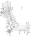
도 1은 본 실시예에 따른 운반 장치의 조립되지 않은 모듈형 구성요소의 사시도이다.
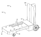
도 2는 본 실시예에 따라 조절 가능한 특징부가 압축된 배향으로 배치된, 조립된 운반 장치의 사시도이다.
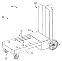
도 3은 본 실시예에 따라 조절 가능한 특징부가 확장된 배향으로 배치된, 조립된 운반 장치의 사시도이다.
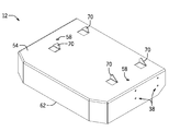
도 4는 본 실시예에 따른 운반 장치에 대한 용접 시스템 구성요소의 조립을 단순화하는 자가 정렬 특징부를 포함하는 전방 판금 패널의 사시도이다.
도 5는 실린더 팬으로부터 연장되는 립(lip)을 갖는 실시예를 도시하는 실린더 팬 조립체의 사시도로서, 립은 본 실시예에 따라 가스 실린더를 팬 내에 로딩하는 데에 일조하는 것인 도면이다.
도 6은 본 실시예에 따라 용접 시스템에 커플링되는, 조립된 운반 장치의 사시도이다.1 is a perspective view of an unassembled, modular component of a carrier apparatus according to this embodiment.
Figure 2 is a perspective view of an assembled conveying device in which adjustable features according to the present embodiment are arranged in a compressed orientation.
3 is a perspective view of an assembled conveying device in which an adjustable feature according to the present embodiment is disposed in an expanded orientation.
4 is a perspective view of a front sheet metal panel including a self-aligning feature that simplifies assembly of a welding system component for a conveying device according to the present embodiment.
Figure 5 is a perspective view of a cylinder fan assembly showing an embodiment having a lip extending from the cylinder pan, wherein the lip serves to load the gas cylinder into the fan in accordance with the present embodiment.
Figure 6 is a perspective view of an assembled conveying device coupled to a welding system in accordance with the present embodiment.
본 개시는 용접 시스템 및/또는 용접 시스템 부속품을 운반하기에 특히 상당히 적합할 수 있는 모듈형 운반 장치 또는 런닝 기어에 관한 것이다. 이에 따라, 운반 장치는 용접 시스템의 전원 또는 다른 구성요소(예컨대, 냉각기)를 수용하는 플랫폼을 포함할 수 있다. 플랫폼은 전방 패널과 하나 이상의 레일로 형성될 수 있는데, 플랫폼의 길이는 운반 장치가 다수의 용접 시스템 구성요소의 크기(예컨대, 전원의 크기)에 맞출 수 있도록 상이한 구성으로 조절 가능할 수 있다. 시스템의 하나 이상의 레일은 레일 또는 레일들에 관하여 전방 패널, 휠 조립체(후방 휠을 포함), 전방 휠, 또는 이들의 조합과의 커플링을 용이하게 하는 대략 2 세트 내지 10 세트의 홀(또는 다른 커플링 특징부)을 각각 포함할 수 있다. 사실상, 각각의 전방 패널, 휠 조립체, 및 전방 휠 중 하나 이상은 하나 이상의 레일에 관하여 독립적으로 병진 운동될 수 있다. 따라서, 레일 또는 레일들은 구매자 또는 최종 사용자가 자신들의 특정한 용례 또는 요구에 적합하도록 운반 장치를 맞춤 제작 가능하게 할 수 있다. The present disclosure relates to a modular conveying apparatus or running gear which may be particularly well suited for conveying a welding system and / or a welding system accessory. Accordingly, the delivery device may include a platform for receiving a power supply or other component (e.g., a cooler) of the welding system. The platform may be formed of a front panel and one or more rails, the length of the platform being adjustable in a different configuration such that the conveying device can be adapted to the size (e.g., size of the power source) of the plurality of welding system components. One or more rails of the system may include approximately 2 to 10 sets of holes (or other sets of holes) that facilitate coupling with the front panel, the wheel assembly (including the rear wheel), the front wheel, Coupling features), respectively. In effect, one or more of each of the front panel, the wheel assembly, and the front wheel may be independently translated relative to one or more rails. Thus, the rails or rails can make the conveyance device customizable so that the buyer or end-user meets their specific use or needs.
전술한 바와 같이, 운반 장치는 운반 장치가 한 장소에서 다른 장소로 사용자에 의해 쉽게 이동될 수 있게 하는 전방 휠 및 후방 휠을 포함할 수 있다. 전방 휠과 후방 휠은 다수의 휠[예컨대, 캐스터(casters)]을 포함할 수 있다. 일 실시예에서, 전방 휠은 휠 지지부를 통해 시스템과 커플링하는 2개의 캐스터를 포함할 수 있고, 후방 휠은 휠 조립체의 액슬(axle)로부터 연장되는 2개의 휠을 포함할 수 있다. 그러나, 임의의 갯수 및/또는 타입의 휠이 사용될 수 있다. 예컨대, 휠 조립체의 구성요소로서 또는 전방 휠로서 대략 1개 내지 10개의 휠이 포함될 수 있다. 후방 휠에 추가하여, 휠 조립체는 적어도 하나의 가스 실린더 병을 수용하도록 실린더 팬 조립체를 포함할 수 있다는 점에 주의해야 한다. 실린더 팬 조립체는 판금으로 형성되는 가스 실린더 지지부를 포함할 수 있고, 가스 실린더 병을 운반 장치에 고정시키도록 스트랩(예컨대, 벨트, 체인, 밴드)을 포함할 수 있다. As described above, the conveying device may include a front wheel and a rear wheel that allow the conveying device to be easily moved by a user from one place to another. The front wheels and the rear wheels may include a plurality of wheels (e.g., casters). In one embodiment, the front wheels may include two casters coupling with the system via the wheel supports, and the rear wheels may include two wheels extending from the axle of the wheel assembly. However, any number and / or type of wheel may be used. For example, approximately one to ten wheels may be included as a component of a wheel assembly or as a front wheel. It should be noted that, in addition to the rear wheels, the wheel assembly may include a cylinder fan assembly to accommodate at least one gas cylinder bottle. The cylinder fan assembly may include a gas cylinder support formed of sheet metal and may include straps (e.g., belts, chains, bands) to secure the gas cylinder bottles to the conveyor.
도 1은 본 실시예에 따른 운반 장치의 조립되지 않은 모듈형 구성요소의 사시도이다. 모듈형 구성요소들의 그룹(조립되든지 조립되지 않든지)은 본 개시에서 총체적으로 운반 장치 또는 시스템(10)으로서 지칭된다. 시스템(10)은 전방 패널(12), 레일(14), 및 휠 조립체(16)를 포함한다. 단일의 대형 레일(14) 대신에 예시적인 실시예에서 2개의 레일(14)을 사용함으로써 재료 및 공간을 보다 효율적으로 사용할 수 있다. 그러나, 시스템은 본 실시예에 따른 단일 레일(14) 또는 다중 레일(14)을 이용하는 여러 구성을 포함할 수 있다. 전방 패널(12)은 레일(14)의 전방 단부(20)와 조절 가능하게 커플링하도록 구성되고 휠 조립체(16)는 레일(14)의 후방 단부(22)와 커플링하도록 구성된다. 아래에서 논의되는 바와 같이, 시스템(10)의 이들 모듈형 구성요소는 함께 커플링되어 용접 시스템 구성요소의 운반을 위한 이동 가능한 장치[즉, 운반 장치(10)]를 형성하도록 구성된다. 이동성을 향상시키기 위해, 시스템(10)은, 전방 패널(12), 레일(14), 또는 이들 양자와 커플링하도록 구성되는 전방 휠(24)(예컨대, 캐스터)을 포함한다. 예시된 실시예에서, 전방 휠(24)은 휠 팬(28; wheel pan)을 포함하는 휠 팬 조립체(26)의 일부인 캐스터를 포함하고, 전방 휠은 휠 팬(28)을 통해 레일(14)과 커플링된다. 시스템(10)은 또한 대응하는 액슬(32)을 따라 휠 조립체(16)로부터 연장되는 후방 휠 또는 백 휠(30)을 포함한다. 일부 실시예에 있어서, 휠(30)은 공통 액슬로부터 연장될 수 있다.1 is a perspective view of an unassembled, modular component of a carrier apparatus according to this embodiment. A group of modular components (whether assembled or not) are collectively referred to herein as a conveyor or
전술한 바와 같이, 전방 패널(12)과 레일(14)은 함께 조절 가능하게 커플링하도록 구성된다. 예시된 실시예에서, 이러한 조절성은 레일(14)의 길이를 따라 상이한 지점에 있는 복수 개의 레일 결합 특징부(36) 및 전방 패널(12)의 결합 특징부(38)에 의해 제공된다. 구체적으로, 예시된 실시예에서, 레일 결합 특징부(36)와 전방 패널(12)의 결합 특징부(38)는, 각 구성요소를 통과하는 개구를 포함하고, 개구는 볼트(도시 생략)가 양 개구를 통과하여 구성요소들을 함께 고정시키게 한다. 다른 실시예에서, 상이한 결합 특징부 또는 파스너가 이용될 수 있다. 사실상, 결합 특징부는 볼트, 스크류, 나사식 개구, 연장부, 인터록(interlock), 스냅(snap), 래치(latch) 등과 같은 파스너를 포함할 수 있다. 또한, 시스템(10)을 조립하고 제조하는 프로세스를 단순화하도록 본질적으로 모든 구성요소 커플링에 대해 동일한 크기의 결합 특징부(예컨대, 동일한 크기의 홀 및 볼트)가 사용될 수 있다. As described above, the
레일 결합 특징부(36)는 각 레일(14)의 원위 단부[전방 단부(20)로서 지시됨] 근처에 있다. 복수 개의 레일 결합 특징부(36) 각각은 전방 패널(12)의 결합 특징부(38) 중 하나와 정렬하도록 구성되어 여러 구성에서 전방 패널(12)과 레일의 커플링을 용이하게 한다. 예컨대, 도 2에 도시된 바와 같이, 최외측 레일 결합 특징부(36)[즉, 전방 단부(20)의 원위 부분에 가장 가까운 레일 결합 특징부(36)]는 확장된 배향(40)에서 전방 패널의 결합 특징부(38)와 커플링될 수 있다. 대안으로, 도 3에 도시된 바와 같이, 최내측 레일 결합 특징부(36)[즉, 전방 단부(20)의 원위 부분으로부터 가장 먼 레일 결합 특징부(36)]는 압축된 배향(41)에서 전방 패널의 결합 특징부(38)와 커플링될 수 있다. 사실상, 전방 패널(12)은 상이한 크기의 용접 시스템 구성요소들을 운반하기 위해 상이한 구성(40, 41)에 대응하는 결합 위치로 레일(14)을 따라 병진될 수 있다. 이를 용이하게 하기 위하여, 레일(14)은 단차형 측벽(42)을 각각 포함하고, 단차형 측벽(42)의 상부면(44)은 제1 단차부(46)와 제2 단차부(48)를 포함하고, 제2 단차부(48)는 제1 단차부(46)를 지나서 연장된다. 아래에서 논의되는 바와 같이, 이들 단차부(46, 48)는 전방 패널(12)과 레일(14)의 정렬 및 결합을 용이하게 하는 레일 립(rail lip)을 지지한다. 단차형 립은 또한 전방 패널(12)과 함께 균등한 지지면의 제공을 용이하게 한다.The
구체적으로, 레일(14)의 단차형 측벽(42) 각각으로부터 연장되는 립과 관련하여, 커플링 립(50)은 단차형 측벽(42)에 관하여 횡방향 배향으로 제1 단차부(46)로부터 연장되고, 지지 립(52)은 제2 단차부(48)로부터 횡방향으로 연장된다. 이들 립 특징부(50, 52)는 시스템 구성요소의 정렬 및 조립을 용이하게 할 뿐만 아니라 용접 시스템 구성요소의 지지를 위한 일관된 기하학적 형태를 제공하도록 전방 패널(12)의 지지 플랫폼(54)[예컨대, 전방 패널(12)의 상부벽을 형성하는 실질적으로 평탄한 금속 플레이트]과 협동할 수 있다. 예컨대, 조립될 때에, 지지 플랫폼(54)의 하부면은 커플링 립(50)의 상부면에 대해 평탄하게 위치 설정되어 전방 패널(12)에 대한 레일(14)의 커플링을 용이하게 할 수 있고 레일(14)에 의한 시스템(10)의 구조적 지지를 제공할 수 있다. 그러한 구조에서, 지지 립(52)은 지지 플랫폼(54)과 정렬될 수 있다. 예컨대, 지지 립(52)과 지지 플랫폼(54)은 본질적으로, 시스템 구성요소가 평평한 배향으로 또는 일관된 각도로 지지 플랫폼(54)과 지지 립(52)을 따라 연장될 수 있도록, 소정 평면을 공유한다. 따라서, 지지 립(52)은 단차형 구조에서 커플링 립(50) 위에 적어도 부분적으로 위치 설정된다. 커플링 립(50)과 지지 립(52) 간의 이러한 오프셋은 레일(14)과 전방 패널(12)의 정렬을 용이하게 할 수 있다. Specifically, with respect to the ribs extending from each stepped
립 특징부(50, 52)는 또한 시스템(10)의 모듈형 구성요소들 간의 조절 가능한 결합을 용이하게 하여 상이한 시스템 배향을 달성하도록 전방 패널(12) 및 레일(14)의 다른 특징부와 협동할 수 있다. 위에서 논의된 바와 같이, 복수 개의 레일 결합 특징부(36) 각각은 전방 패널(12)의 결합 특징부(38)들 중 하나와 정렬하도록 구성되어 상이한 구성에서 전방 패널(12)과 레일(14)의 커플링을 용이하게 한다. 유사하고 대응하는 방식으로, 커플링 립(50)은 레일(14)의 전방 단부(20)에 근접한 커플링 립(50)의 길이를 따라 상이한 지점에 복수 개의 용접 시스템 결합 특징부(56)를 포함한다. 복수 개의 시스템 결합 특징부(56) 각각은 전방 패널(12)의 용접 시스템 결합 특징부(58)와 정렬하도록 구성되어, 상이한 구성에서 레일(14) 및 전방 패널(12)과 용접 시스템 구성요소의 커플링을 용이하게 한다. 전술한 복수 개의 레일 결합 특징부(36) 및 전방 패널(12)의 결합 특징부(38)와 마찬가지로, 복수 개의 시스템 결합 특징부(56)와 용접 시스템 결합 특징부(58)는 상이한 구성에서 전방 패널(12)과 레일(14)의 커플링을 용이하게 하기 위해 협동하도록 구성된다. 예컨대, 상이한 시스템 결합 특징부(56)는 시스템의 원하는 구성[예컨대, 확장된 배향(40) 또는 압축된 배향(41)]에 따라 용접 시스템 결합 특징부(58)와 정렬될 수 있다. 사실상, 예시된 실시예에서 개구인, 정렬된 결합 특징부(56, 58) 모두를 스크류, 볼트, 또는 다른 파스너가 통과하여 레일(14)과 전방 패널(12)을 함께 커플링시킬 수 있다. 게다가, 결합 특징부(56, 58)는 용접 시스템 구성요소(예컨대, 전원 또는 냉각기)와의 커플링을 용이하게 할 수 있다. 예컨대, 볼트는 결합 특징부(56, 58) 양자를 통과하여 용접 시스템 구성요소의 결합 특징부와 결합할 수 있다.The rib features 50,52 may also be configured to cooperate with other features of the
예시된 실시예는 전방 패널(12)의 대응하는 연결 특징부[예컨대, 결합 특징부(38)와 용접 시스템 결합 특징부(58)]보다 갯수가 많은, 다수의 연결 특징부[예컨대, 레일 결합 특징부(36)와 용접 시스템 결합 특징부(56)]를 레일 상에 보여준다는 것을 유념해야 한다. 이로 인해, 상이한 시스템 구성[예컨대, 구성(40) 및 구성(41)]을 달성하도록 전방 패널(12)의 동일한 연결 특징부가 레일(14)을 따라 상이한 세트의 연결 특징부와 연결되게 된다. 그러나, 다른 실시예에서, 상이한 갯수 및 비율의 연결 특징부가 레일(14) 및 전방 패널(12)에 대해 포함될 수 있다. 사실상, 이로 인해, 시스템(10)의 각각의 사용자 구성을 갖는 추가 융통성을 제공할 수 있다. 유사하게 시스템의 다른 양태는 레일(14)과 전방 패널(12)의 조절성과 유사한 방식으로 조절성을 제공할 수 있다는 점에 주의해야 한다. 예컨대, 휠 조립체(16)와 휠 팬 조립체(26)는 몇몇 실시예에서 레일(14)에 대해 조절 가능할 수 있다.The illustrated embodiment has a number of connection features (e.g., rail coupling (s)) that are more numerous than the corresponding connection features (e.g.,
복수 개의 레일 결합 특징부(36)와 복수 개의 시스템 결합 특징부(56)는 레일(14)과 전방 패널(12) 간에 견고한 커플링을 제공하도록 서로에 관하여 배향될 수 있다. 예컨대, 레일 결합 특징부(36)와 시스템 결합 특징부(56)는 서로에 대해 가로지르는 방식으로 전방 패널(12)과 결합하도록 배치될 수 있다. 이는, 상이한 방향 성분을 갖는, 시스템에 인가되는 힘에 관하여 시스템(10)을 지지할 수 있게 한다. 레일 결합 특징부(36)와 시스템 결합 특징부(56)의 특정한 구조는 이 관계의 예를 제공하기 위해 아래에서 논의된다. The plurality of rail coupling features 36 and the plurality of system coupling features 56 may be oriented with respect to one another to provide a rigid coupling between the
예시된 실시예에서, 복수 개의 레일 결합 특징부(36)는 전방 패널(12)의 결합 특징부(38)와의 정렬이 가능하게 하도록 단차형 측벽(42)의 면에 관하여 횡방향으로 배향된다. 사실상, 전방 패널(12)의 제시된 결합 특징부(38)는, 결합 특징부(38)와 레일 결합 특징부(36)의 정렬을 용이하게 하도록 지지 플랫폼(54)의 둘레로부터 횡방향으로 하방을 향해 그리고 단차형 측벽(42)과 실질적으로 평행하게 연장되는 스커트(62; skirt)의 구성요소이다. 결합 특징부(38)와 레일 결합 특징부(36)의 커플링은, 스커트(62)의 면과 단차형 측벽(42)의 면을 가로지르는 제1 방향을 따른 커플링을 포함한다. 또한, 제시된 시스템 결합 특징부(56)는 커플링 립(50)의 면을 가로지르는 배향으로 커플링 립(50)을 통해 연장되고, 지지 플랫폼(54)의 면을 가로지르는 방향으로 지지 플랫폼(54)을 통해 연장되는 용접 시스템 결합 특징부(58)와 커플링될 수 있다. 지지 플랫폼(54)의 면과 측벽(42)의 면이 가로지르기 때문에, 관련된 커플링이 또한 가로지르고 서로에 대한 방향성 지지를 제공한다. In the illustrated embodiment, the plurality of
레일(14)과 전방 패널(12)의 커플링은 전방 패널(12)을 레일(14)과 활주 가능하게 결합시키는 것을 포함할 수 있다. 구체적으로, 지지 플랫폼(54)과 스커트(62)는, 전방 패널(12)과의 적절한 정렬 상태로 레일(14)을 안내하도록 협동할 수 있다. 전방 패널(12)이 레일(14)과의 조절 가능한 결합을 위해 레일(14)에 관하여 병진될 때에, 지지 플랫폼(54)은 지지 플랫폼(54)의 하부면이 커플링 립(50)의 상부면과 평탄하게 이웃하도록 커플링 립(50) 위에서 활주될 수 있다. 또한, 스커트(62)의 내측 표면은 단차형 측벽(42)의 외측 표면과 평탄하게 이웃하도록 위치 설정될 수 있다. 조합하여, 이들의 맞댐은 각각의 구성요소의 각각의 결합 특징부가 커플링을 위해 정렬하도록 전방 패널(12)에 관하여 레일(14)을 안내하는 것을 용이하게 할 수 있다. 이는 관련된 시스템 구성요소들의 조립을 용이하게 할 수 있다. 또한, 지지 플랫폼(54)의 하부면이 커플링 립(50)의 상부면과 평탄하게 이웃할 때에, 지지 립(52)의 에지는 지지 플랫폼(54)의 에지와 정렬될 수 있어, 이들 에지는 궁극적으로 전방 패널(12)이 레일(14)을 따라 전후로 활주할 때에 이웃하게 된다. 따라서, 커플링 립(50) 및 지지 플랫폼(54)에 대한 지지 립(52)의 배향은, 레일 결합 특징부(36)와 시스템 결합 특징부(56)을 넘어서는 전방 패널(12)의 병진에 저항하는 기능을 할 수 있다. The coupling of the
전방 패널(12)은 판금으로 형성될 수 있다. 사실상, 스커트(62)는 판금의 다른 피스를 포함할 수 있는, 지지 플랫폼(54)으로부터 횡방향으로 연장되는 판금의 다양한 피스(piece)를 포함할 수 있다. 전방 패널(12)은 다수의 레벨의 기능을 시스템(10)에 추가한다. 예컨대, 스커트(62)는 전방 휠(25)을 위한 보호 배리어와, 전술한 바와 같이 레일(14)과 결합하기 위한 안내부를 제공한다. 또한, 전방 패널(12)은 조립될 때에 시스템(10)의 조립 및/또는 사용을 단순화시키도록 자가 정렬 특징부(70)를 포함할 수 있다. 자가 정렬 특징부(70)는 용접 시스템 구성요소를 시스템 결합 특징부(56, 58)와 정렬시키기 위해 용접 시스템 구성요소의 특징부와 협동하도록 구성될 수 있다. 예컨대, 자가 정렬 특징부(70)는 용접 시스템 구성요소의 베이스에 있는 하나 이상의 개구에 끼워질 수 있다. 다른 예에서, 자가 정렬 특징부(70)는 베이스를 수용하도록 배치될 수 있다. 즉, 자가 정렬 특징부(70)는 용접 시스템 특징부의 베이스가 실질적으로 고정된 배향으로 끼워지는 리셉터클(receptacle)을 형성할 수 있다. 자가 정렬 특징부(70)는 또한 플랫폼, 베이스, 또는 용접 시스템 구성요소의 다른 양태와 인터로킹하거나, 이웃하거나, 달리 결합함으로서 배치 특징부로서 기능할 수 있다. 예컨대, 탭은 용접 시스템 구성요소의 리세스 내에 배치될 수 있다. 자가 정렬 특징부(70)와 정렬될 때에, 용접 시스템 구성요소의 결합 특징부는 이에 따라 특정한 조립 배향으로 시스템 결합 특징부(56, 58)와 정렬할 수 있다.The
예시된 실시예에서, 자가 정렬 특징부(70)는 전방 패널(12)로부터 다수의 연장부를 포함할 수 있다. 이들 자가 정렬 특징부(70)는 전방 패널(12)의 사시도인 도 4에서 더욱 쉽게 관찰할 수 있다. 예시된 실시예의 자가 정렬 특징부(70)는 지지 플랫폼(54)으로부터 특별하게 연장된다. 그러나, 다른 실시예에서, 자가 정렬 특징부(70)는 전방 패널(12)의 임의의 부분[예컨대, 스커트(62)]으로부터 연장될 수 있다. 게다가, 도 4에 명백하게 도시된 바와 같이, 자가 정렬 특징부(70)는, 지지 플랫폼으로부터 연장되고 지지 플랫폼(54)에 대해 횡방향 배향으로 있는 탭을 포함한다. 이 실시예의 탭은 지지 플랫폼(54)을 형성하는 판금과 일체형이고 횡방향 배향으로 만곡된다. 그러나, 다른 실시예에서, 탭은 지지 플랫폼 또는 전방 패널(12)의 몇몇의 다른 양태에 커플링될 수 있다. 몇몇 실시예에서, 레일(14)은 물론 정렬 특징부를 포함할 수 있다. 더욱이, 특정한 갯수의 자가 정렬 특징부(70)가 채용될 수 있다. 예컨대, 자가 정렬 특징부(70)로서 전방 패널(12) 상에 대략 2개 내지 20개의 내장 탭(built-in tab)이 형성될 수 있다. In the illustrated embodiment, the self-aligning
휠 조립체(16)는 배치면을 갖도록 설계될 수 있어, 레일(14)이 쉽게 삽입되고, 자가 정렬되며, 이후 특별한 공구의 사용 없이 사용자에 의해 휠 조립체에 볼트 결합될 수 있다. 몇몇 실시예에서, 휠 조립체(16)는 가스 실린더를 유지하도록 구성되지 않는다. 그러나, 도 1 내지 도 3에 의해 예시된 실시예에서, 휠 조립체(16)는 실린더 팬 조립체(80)를 특별히 포함한다. 실린더 팬 조립체(80)는, 측벽(82), 상부벽으로서의 클리어린스 패널(84; clearance panel), 후방벽(86), 및 실린더 팬(88; cylinder pan)을 갖는 하우징을 포함한다. 레일(14)은 실린더 팬 조립체(80) 내의 레일 포트(90)를 통해 실린더 팬 조립체(80)에 결합된다. 이들 레일 포트(90)는 실린더 팬 조립체(80)의 결합 특징부(94)와 레일(14)의 후방 결합 특징부(92)의 정렬을 용이하게 한다. 구체적으로, 레일 포트(90)는 실린더 팬 조립체(80)의 다양한 벽들[예컨대, 측벽(82), 클리어린스 패널(84), 및 후방벽(86)]의 가장자리에 의해 형성되는 경계들을 포함하고, 이들 경계는 실린더 팬 조립체(80)와의 커플링을 위해 레일을 정렬시키는 배치면의 역할을 한다. 레일 포트(90)에 의해 제공되는 정렬 외에, 실린더 팬 조립체(80)는 또한 클리어린스 패널(84)과 레일 포트(90) 및 설치된 실린더에 대한 관계를 통해 가스 실린더 및 설치된 용접 시스템 구성요소 간에 빌트인 오프셋(built-in offset)을 제공한다. 이로 인해, 용접 시스템 구성요소가 시스템(10) 상에 설치되는 동안에 작동될 때에 가스 실린더 병의 잠재적인 과열을 방지할 수 있다. 사실상, 시스템(10)이 조립되면, 레일(14)의 상부면[지지 립(52)의 상부면]은 클리어린스 패널(84)의 하부면에 이웃하고 전방 패널(12)을 향하는 클리어린스 패널(84)의 에지는 용접 시스템 구성요소[시스템(10)에 부착될 때]와 적어도 하나의 가스 실린더 병[실린더 팬(88) 내에 배치될 때] 사이의 공간을 냉각시키는 경계를 형성한다. 클리어린스 패널(84)의 에지는 지지 레일(52) 위로 연장되고 레일(14)을 따른 그리고 또한 시스템(10)의 후방을 향한 용접 시스템 구성요소의 활주에 저항할 수 있고, 거기에 가스 병이 보관된다. The
가스 실린더 병을 위한 편평한 지지부를 포함할 수 있는 실린더 팬(88)은, 실린더 팬 조립체(80)의 기벽(base wall)의 기능을 한다. 실린더 팬(88)은 운반 장치 또는 시스템(10)의 조작자가 가스 실린더 병을 운반 장치(10)로 로딩하게 할 수 있다. 실린더 팬(88)은 다양한 크기 및 기하학적 형태의 가스 실린더 병을 유지 및 지지하도록 설계된다. 실린더 팬(88)은 측벽(82) 및/또는 후방벽(86)과 커플링될 수 있다(예컨대, 용접되거나 파스너를 통해 커플링됨). 구체적으로, 실린더 팬(82)은 상부에 위치 설정되는 가스 실린더를 지지하기 위해 실린더 팬 조립체(80)의 다른 양태와 협동하도록 구성된다. 액슬(32)에 커플링되는 휠(30)이 없는 실린더 팬 조립체(80)의 사시도인 도 5에 가장 잘 예시된 바와 같이, 실린더 팬(88)은 적어도 하나의 가스 실린더 병의 로딩을 용이하게 하도록 실린더 팬(88)의 에지 상에 립(98)을 포함한다. 이 립(98)은 다른 표면(예컨대, 바닥, 선반)으로부터 실린더 팬(88) 내로 평활한 천이를 가능하게 함으로써 이 로딩 프로세스를 단순화할 수 있다. 립(98)의 특정한 특징은 가스 병을 로딩하고 유지할 목적을 실시하도록 특히 구성된다. 사실상, 립(98)은 대체로 사인 곡선인 것으로 이해되는 사인 곡선 형상을 포함한다. 구체적으로, 립(98)은 실린더 팬(88)의 상부면(104) 위로 연장되는 피크(102; peak)와, 상부면(104) 아래로 연장되는 경사부(104)를 포함한다. 따라서, 립(98)은, 가스 실린더 병이 실린더 팬(88) 위로 그리고 안쪽으로 굴러가도록 하는 경사로를 제공하면서, 또한 실린더 팬(88) 내에 있다면 가스 실린더 병이 실린더 팬(88)에서 빠져나기 위해서는 굴러 넘어가야 하는 장벽을 제공한다. The
또한, 도 1 내지 도 3에 예시된 바와 같이, 실린더 팬 조립체(80)는 실린더 팬 조립체(80)로부터 실린더 팬(88)을 가로지르는 방향으로 연장되는 적어도 하나의 실린더 지지부(202)를 포함할 수 있다. 실린더 지지부(202)는 실린더 팬(88) 상에 안착하도록 구성된다. 또한, 도 1 내지 도 3 및 도 5를 함께 관찰함으로서 부분적으로 예시되는 바와 같이, 실린더 지지부(202)는 실린더 지지부 부착 특징부(206) 및 실린더 팬 조립체(80)의 대응하는 부착 특징부(208)를 통해 클리어린스 패널(84)의 립(204)과 커플링하도록 구성된다. 다른 실시예에서, 상이한 커플링 구조가 채용될 수 있다. 조작자는 가스 실린더 병이 가스 실린더 지지부(202) 중 하나와 접촉할 때까지 가스 실린더 병을 실린더 팬(88) 내로 안내하기 위해 립(98)을 사용할 수 있고, 이어서 조작자는 가스 실린더 병을 가스 실린더 지지부(202)에 고정시킬 수 있다. 실린더 팬(88) 및 실린더 지지부(202)는 다수의 상이한 가스 실린더 병의 기하학적 형태에 적응하도록 협동할 수 있다.1 to 3, the
예시된 실시예에는, 3면 패널을 각각 포함하는 2개의 실린더 지지부(202)가 존재한다. 3면 패널은 시스템(10)에 설치될 때에 가스 실린더 병을 실린더 지지부(202) 내에 수용하는 것을 용이하게 하도록 시스템(10)의 중앙선을 등지고 중앙선으로부터 멀어지게 각도를 이루는 대체로 C형 단면을 갖는다. 구체적으로, 예시된 바와 같이, 제1의 3면 패널(214)의 패널(212)은 제2의 3면 패널(218)의 패널(216)과 정렬되어 제2의 3면 패널에 대해 평탄하게 배치되어 2개의 3면 패널(216, 218)의 3족 구조를 달성한다. 즉, 2개의 실린더 지지부(202)의 단면은 3족 구조와 유사하게 보인다. 다수의 패널의 사용은 가스 실린더 병이 이웃하는 복수 개의 표면을 제공하고, 이는 다수의 방향으로 병의 지지부를 제공한다는 것을 유념해야 한다. 패널은 또한 다수의 상이한 크기의 병을 수용하도록 구성될 수 있다. 사실상, 몇몇 실시예에서, 패널들의 구조는 상이한 타입의 병에 맞도록 조절될 수 있다. 사실상, 실린더 지지부(202)는 병 둘레에서 물리적으로 래핑(wrapping)될 수 있다. 가스 실린더 병을 위한 추가 지지부는 실린더 지지부(202)의 에지에 있는 리셉터클(224)들 사이에서 연장되는 실린더 지지 립(222) 또는 코드(예컨대, 체인, 로프, 와이어, 케이블)에 의해 제공될 수 있다. In the illustrated embodiment, there are two cylinder supports 202 each including a three-sided panel. The three-sided panel has a generally C-shaped cross-section that angles away from the centerline of the
도 6은 본 실시예에 따라 용접 시스템(302)이 상부에 설치된 시스템(10)을 예시한다. 도 6에 제공된 실시예에 의해 예시된 바와 같이, 특정한 실시예에서, 휠 조립체(16)는 실린더 팬 조립체(80)를 포함하지 않는다. 실린더 팬 조립체(80)에 관한 특징부를 제외하면 사용자가 운반되는 용접 시스템과 동반하도록 가스 실린더를 요구하지 않는 상황에서 운반 장치 또는 시스템(10)의 이동성을 향상시킬 수 있다. 게다가, 운반 장치(10)의 모듈성의 다른 양태가 포함될 수 있다. 예컨대, 특정한 실시예에서, 운반 장치(10)는 케이블을 매달기 위한 케이블 행거(306; cable hanger), 와이어 공급기를 조종하기 위한 공급기 지지부(308) 및 선회부(310; swivel), PC & LED/LCD 지지 스탠드(312), 및 시스템(10)에 부속품을 달기 위해 이용될 수 있는 다른 모듈형 구성요소를 포함할 수 있다. Figure 6 illustrates a
본 실시예는 모듈형 용접 구성요소 운반 시스템을 조립하는 방법을 포함할 수 있다. 구체적으로, 상기 방법은 한 쌍의 레일의 상부벽이 전방 패널의 지지 플랫폼에 이웃하고 한 쌍의 레일의 측벽이 전방 패널의 패널 스커트의 상이한 부분에 이웃하도록 한 쌍의 레일의 제1 단부를 전방 패널 내에 수용하는 것을 포함할 수 있다. 상기 방법은 한 쌍의 레일 각각의 복수 개의 결합 특징부가 전방 패널의 결합 특징부와 정렬되는 것에 따라 운반 시스템의 압축된 배향 또는 확장된 배향을 형성하도록 전방 패널의 결합 특징부를 한 쌍의 레일 각각의 복수 개의 결합 특징부 중 적어도 2개와 정렬시키는 것을 더 포함할 수 있다. 게다가, 상기 방법은 한 쌍의 레일의 상부벽이 실린더 팬 조립체의 상부 패널에 이웃하고 한 쌍의 레일의 측벽이 실린더 팬 조립체의 상이한 측면 패널에 이웃하도록 한 쌍의 레일의 제2 단부를 실린더 팬 조립체 내에 수용하는 것을 포함할 수 있는데, 실린더 팬 조립체는 실린더 팬의 에지로부터 한 쌍의 레일에 대향하는 방향으로 연장되는 경사진 립과 실린더 팬을 가로질러 연장되는 실린더 지지부를 갖는 실린더 팬을 포함한다. 상기 방법은, 또한 전방 패널에 대한 부착을 위해 용접 시스템 구성요소를 전방 패널의 정렬 특징부와 정렬시키는 것, 그리고 용접 시스템 구성요소와 실린더 지지부 간의 오프셋 거리를 실린더 팬 조립체의 클리어린스 패널에 의해 유지하는 것을 포함할 수 있다.The present embodiment may include a method of assembling a modular welded component delivery system. Specifically, the method is characterized in that the upper wall of the pair of rails is adjacent to the support platform of the front panel, and the side walls of the pair of rails are adjacent to different parts of the panel skirt of the front panel, Lt; RTI ID = 0.0 > panel. ≪ / RTI > The method includes attaching the joining feature of the front panel to each of the pair of rails to form a compressed or extended orientation of the conveying system as the plurality of engaging features of each of the pair of rails are aligned with the engaging features of the front panel And aligning the at least two of the plurality of coupling features. In addition, the method further comprises positioning the second end of the pair of rails such that the top wall of the pair of rails is adjacent to the top panel of the cylinder fan assembly and the side walls of the pair of rails are adjacent to the different side panels of the cylinder fan assembly, Wherein the cylinder fan assembly includes a cylinder pan having an inclined lip extending in a direction opposite to the pair of rails from an edge of the cylinder pan and a cylinder support extending across the cylinder pan . The method also includes aligning the weld system component with the alignment features of the front panel for attachment to the front panel and maintaining the offset distance between the weld system component and the cylinder support by a clear rinse panel of the cylinder fan assembly Lt; / RTI >
본 실시예는 특별한 공구가 요구되지 않으면서 사용자에 의해 현장 조립이 용이한 용접 시스템 운반 장치를 제공할 수 있다. 조립은 정렬 안내부를 채용하는 전체적으로 유사한 결합 특징부의 사용과, 모듈형 특징부의 제공에 의해 용이해질 수 있다. 조립체 구성요소 및 모듈형 특징부로서 동일한(예컨대, 표준화된) 부품을 이용하면, 제조 물품 목록을 낮은 수준으로 유지하고 관련 비용을 절감하는 것을 용이하게 할 수 있다. 시스템의 모듈형 특징은 또한 포장 및 선적을 용이하게 한다. 또한, 시스템의 모듈 양태는 조립하는 동안에 부품들을 배향하는 데에 있어서 무가치한 추가 수동 노력을 감소시킬 수 있다. The present embodiment can provide a welding system carrying apparatus which is easy to be field-assembled by a user without requiring a special tool. The assembly can be facilitated by the use of generally similar coupling features employing alignment guides and by the provision of modular features. The use of identical (e.g., standardized) components as assembly components and modular features may facilitate keeping inventory listings low and reducing associated costs. The modular nature of the system also facilitates packaging and shipping. In addition, the modular aspects of the system can reduce the unnecessary manual effort in orienting the components during assembly.
본 개시가 다양한 변형 및 대안적인 형태에 민감할 수 있지만, 특정한 실시예를 도면 및 표에 일례로 나타내고 본 명세서에서 상세하게 설명하였다. 그러나, 이러한 실시예는 개시된 특별한 형태로 제한되도록 의도되지 않는다. 오히려, 본 개시는 아래의 첨부된 청구범위에 의해 한정되는 본 개시의 사상 및 범위 내에 속하는 모든 변형, 균등물, 및 대안을 포함한다. 또한, 개별적인 실시예가 본 명세서에서 논의되고 있지만, 본 개시는 모든 조합을 포함하도록 의도된다. While this disclosure may be susceptible to various modifications and alternative forms, specific embodiments have been shown by way of example in the drawings and tables and have been described in detail herein. However, such embodiments are not intended to be limited to the particular forms disclosed. Rather, the disclosure includes all variations, equivalents, and alternatives falling within the spirit and scope of the disclosure as defined by the following appended claims. Also, although individual embodiments are discussed herein, this disclosure is intended to include all combinations.
10 : 운반 장치 또는 시스템
12 : 전방 패널
14 : 레일
16 : 휠 조립체
24 : 전방 휠10: Carrier or system
12: Front panel
14: rail
16: Wheel assembly
24: front wheel
Claims (20)
용접 시스템 구성요소를 지지하도록 구성되는 지지 플랫폼을 포함하는 전방 패널;
복수 개의 제1 휠을 포함하는 휠 조립체;
레일의 제1 단부에 근접한 전방 패널과 조절 가능하게 커플링하도록 구성되고 레일의 제2 단부에 근접한 휠 조립체와 커플링하도록 구성되는 레일;
휠 조립체의 벽과 결합하기 위해 레일을 수용하고 정렬시키도록 구성되는 휠 조립체의 배치면; 및
전방 패널과 결합되거나 레일의 제1 단부에 근접하도록 구성되는 복수 개의 제2 휠
을 포함하는 모듈형 용접 구성요소 운반 시스템.A modular weld component delivery system comprising:
A front panel comprising a support platform configured to support a welding system component;
A wheel assembly including a plurality of first wheels;
A rail configured to adjustably couple with a front panel proximate a first end of the rail and to couple with a wheel assembly proximate a second end of the rail;
A placement surface of the wheel assembly configured to receive and align the rails for engagement with the wall of the wheel assembly; And
A plurality of second wheels coupled to the front panel or configured to approach the first end of the rails
Wherein the modular welded component delivery system comprises:
상기 레일의 길이를 따라 그리고 레일의 원위 단부에 근접하게 다양한 지점에 있는 복수 개의 레일 결합 특징부
를 포함하고, 상기 복수 개의 레일 결합 특징부 각각은 전방 패널의 결합 특징부와 정렬하도록 구성되어 레일과 전방 패널을 다양한 구성으로 커플링하는 것을 용이하게 하는 것인 모듈형 용접 구성요소 운반 시스템.The method according to claim 1,
A plurality of rail coupling features at various points along the length of the rail and proximate the distal end of the rail,
Wherein each of the plurality of rail coupling features is configured to align with the coupling feature of the front panel to facilitate coupling the rail and the front panel in various configurations.
베이스를 포함하는 용접 시스템 구성요소
를 포함하고, 전방 패널의 정렬 특징부는 용접 시스템 구성요소의 결합 특징부가 지지 플랫폼 또는 레일의 용접 시스템 결합 특징부와 정렬하도록 용접 시스템 구성요소의 베이스와 결합되는 것인 모듈형 용접 구성요소 운반 시스템.The method of claim 3,
A weld system component comprising a base
Wherein the alignment feature of the front panel is coupled to the base of the welding system component such that the coupling feature of the welding system component is aligned with the welding system coupling feature of the support platform or rail.
상기 제1 단차부로부터 연장되고 단차형 측벽을 가로지르는 커플링 립(coupling lip)
을 포함하는 모듈형 용접 구성요소 운반 시스템.9. The method of claim 8,
A coupling lip extending from the first step and transverse to the stepped side wall,
Wherein the modular welded component delivery system comprises:
상기 제2 단차부로부터 횡방향으로 연장되는 지지 립
을 포함하고, 지지 립의 에지는 커플링 립의 상부면이 지지 플랫폼의 하부면에 이웃할 때에 지지 플랫폼의 에지와 정렬되는 것인 모듈형 용접 구성요소 운반 시스템.10. The method of claim 9,
And a second support portion extending laterally from the second step portion,
Wherein an edge of the support lip is aligned with the edge of the support platform when the upper surface of the coupling lip is adjacent the lower surface of the support platform.
복수 개의 레일의 제1 단부에 근접한 전방 패널과 조절 가능하게 커플링하도록 구성되고 복수 개의 레일의 제2 단부에 근접한 휠 조립체와 커플링하도록 구성되는 복수 개의 레일
을 포함하는 모듈형 용접 구성요소 운반 시스템.The method according to claim 1,
A plurality of rails configured to adjustably couple with a front panel proximate a first end of the plurality of rails and configured to couple with a wheel assembly proximate a second end of the plurality of rails,
Wherein the modular welded component delivery system comprises:
용접 시스템 구성요소를 지지하도록 구성되는 지지 플랫폼을 포함하는 전방 패널;
복수 개의 후방 휠과, 적어도 하나의 가스 실린더 병을 지지하도록 구성되는 실린더 팬(cylinder pan)을 포함하는 실린더 팬 조립체;
레일의 제1 단부에 근접한 전방 패널과 조절 가능하게 커플링되고 레일의 제2 단부에 근접한 실린더 팬의 안내로를 따라 커플링되는 레일; 및
전방 패널과 커플링되거나 레일의 제1 단부에 근접하도록 구성되는 복수 개의 전방 휠
을 포함하는 용접 시스템 운반 시스템.As a welding system carrying system,
A front panel comprising a support platform configured to support a welding system component;
A cylinder pan assembly including a plurality of rear wheels and a cylinder pan configured to support at least one gas cylinder bottle;
A rail adjustably coupled with the front panel proximate the first end of the rail and coupled along the guide path of the cylinder pan adjacent the second end of the rail; And
A plurality of front wheels coupled to the front panel and configured to be proximate the first end of the rails,
And a welding system.
상기 실린더 팬 조립체로부터 실린더 팬을 가로지르는 방향으로 연장되는 실린더 지지부
를 포함하고, 상기 실린더 지지부는 적어도 하나의 3면 패널을 포함하는 것인 용접 시스템 운반 시스템.15. The method of claim 14,
A cylinder support member extending from the cylinder fan assembly in a direction transverse to the cylinder pan,
Wherein the cylinder support comprises at least one three-sided panel.
한 쌍의 레일의 상부벽이 전방 패널의 지지 플랫폼에 이웃하고 한 쌍의 레일의 측벽이 전방 패널의 패널 스커트의 상이한 부분에 이웃하도록 한 쌍의 레일의 제1 단부를 전방 패널 내에 수용하는 것;
한 쌍의 레일 각각의 복수 개의 결합 특징부가 전방 패널의 결합 특징부와 정렬되는 것에 따라 운반 시스템의 압축된 배향 또는 확장된 배향을 형성하도록 전방 패널의 결합 특징부를 한 쌍의 레일 각각의 복수 개의 결합 특징부 중 적어도 2개와 정렬시키는 것;
한 쌍의 레일의 상부벽이 실린더 팬 조립체의 상부 패널에 이웃하고 한 쌍의 레일의 측벽이 실린더 팬 조립체의 상이한 측면 패널에 이웃하도록 한 쌍의 레일의 제2 단부를 실린더 팬 조립체 내에 수용하되, 실린더 팬 조립체는 실린더 팬의 에지로부터 한 쌍의 레일에 대향하는 방향으로 연장되는 경사진 립과 실린더 팬을 가로질러 연장되는 실린더 지지부를 갖는 실린더 팬을 포함하는 것;
전방 패널에 대한 부착을 위해 용접 시스템 구성요소를 전방 패널의 정렬 특징부와 정렬시키는 것; 그리고
용접 시스템 구성요소와 실린더 지지부 간의 오프셋 거리를 실린더 팬 조립체의 클리어린스 패널(clearance panel)에 의해 유지하는 것
을 포함하는 모듈형 용접 구성요소 운반 시스템을 조립하는 방법.A method of assembling a modular welded component delivery system,
Receiving a first end of a pair of rails in the front panel such that a top wall of the pair of rails is adjacent to a support platform of the front panel and a side wall of the pair of rails is adjacent to a different portion of the panel skirt of the front panel;
The joining feature of the front panel may be used as a plurality of joining features of each of the pair of rails to form a compressed or extended orientation of the conveying system as the plurality of joining features of each of the pair of rails are aligned with the joining feature of the front panel. Alignment with at least two of the features;
Accommodating a second end of a pair of rails in the cylinder fan assembly such that a top wall of the pair of rails is adjacent to an upper panel of the cylinder fan assembly and a side wall of the pair of rails is adjacent to a different side panel of the cylinder fan assembly, The cylinder fan assembly including a cylinder pan having an inclined lip extending in a direction opposite to the pair of rails from an edge of the cylinder pan and a cylinder support extending across the cylinder pan;
Aligning the weld system components with alignment features on the front panel for attachment to the front panel; And
Maintaining the offset distance between the weld system component and the cylinder support by a clearance panel of the cylinder fan assembly
The method comprising the steps of:
Applications Claiming Priority (5)
| Application Number | Priority Date | Filing Date | Title |
|---|---|---|---|
| US201261698035P | 2012-09-07 | 2012-09-07 | |
| US61/698,035 | 2012-09-07 | ||
| US13/840,174 US9102347B2 (en) | 2012-09-07 | 2013-03-15 | System and method for modular transportation of a welding system |
| US13/840,174 | 2013-03-15 | ||
| PCT/US2013/058345 WO2014039734A1 (en) | 2012-09-07 | 2013-09-05 | System and method for modular transportation of a welding system |
Publications (1)
| Publication Number | Publication Date |
|---|---|
| KR20150052837A true KR20150052837A (en) | 2015-05-14 |
Family
ID=50232501
Family Applications (1)
| Application Number | Title | Priority Date | Filing Date |
|---|---|---|---|
| KR1020157002782A KR20150052837A (en) | 2012-09-07 | 2013-09-05 | System and method for modular transportation of a welding system |
Country Status (11)
| Country | Link |
|---|---|
| US (1) | US9102347B2 (en) |
| EP (1) | EP2892789A1 (en) |
| JP (1) | JP2015533708A (en) |
| KR (1) | KR20150052837A (en) |
| CN (1) | CN104812655B (en) |
| AU (1) | AU2013312497B2 (en) |
| BR (1) | BR112015003730A2 (en) |
| CA (1) | CA2878243C (en) |
| IN (1) | IN2014DN11276A (en) |
| MX (1) | MX350857B (en) |
| WO (1) | WO2014039734A1 (en) |
Families Citing this family (6)
| Publication number | Priority date | Publication date | Assignee | Title |
|---|---|---|---|---|
| US9102347B2 (en) * | 2012-09-07 | 2015-08-11 | Illinois Tool Works Inc. | System and method for modular transportation of a welding system |
| CA3030020A1 (en) * | 2016-07-14 | 2018-01-18 | Esab Ab | Portable welding system with a main case having mechanical attachments mechanism for facilitating coupling |
| US20200023872A1 (en) * | 2018-07-23 | 2020-01-23 | Matthew McCrillis | Welding Cart |
| CN109335534B (en) * | 2018-09-29 | 2024-02-09 | 广东阿达智能装备有限公司 | Rail device for conveying material sheets and metal wire bonding machine |
| US11365103B2 (en) * | 2019-03-27 | 2022-06-21 | Hyster-Yale Group, Inc. | Modular fork assembly for a material-handling vehicle |
| JP7269551B2 (en) * | 2019-08-27 | 2023-05-09 | スズキ株式会社 | electric vehicle |
Family Cites Families (31)
| Publication number | Priority date | Publication date | Assignee | Title |
|---|---|---|---|---|
| US4302023A (en) * | 1979-05-11 | 1981-11-24 | Kiesz Lloyd W | Dolly with vertically adjustable shelf |
| US5012879A (en) * | 1990-06-26 | 1991-05-07 | Bienek Richard J | Self-propelled jacking apparatus for factory constructed buildings |
| US5299817A (en) * | 1992-06-09 | 1994-04-05 | Seth Chang | Adjustable mobile base |
| US5249823A (en) * | 1992-10-09 | 1993-10-05 | E.B.S. Equipment Services, Inc. | Size variable cart |
| US5328192A (en) * | 1993-03-18 | 1994-07-12 | Thompson John R | Manual pull-type carrier for transporting a large game carcass |
| US5440098A (en) * | 1993-12-23 | 1995-08-08 | Miller Electric Manufacturing Co. | Gas cylinder lifting system |
| US6079941A (en) * | 1995-08-14 | 2000-06-27 | Lee Inventions, Inc. | Moving system |
| US5779252A (en) * | 1996-02-05 | 1998-07-14 | Bolton, Jr.; Albert | Cooler caddy |
| US5730891A (en) * | 1996-04-16 | 1998-03-24 | The Lincoln Electric Company | Undercarriage for welder |
| US5816604A (en) * | 1997-05-27 | 1998-10-06 | Hsieh; Hung-Ching | Stretchable and foldable cart |
| US6223908B1 (en) * | 1999-09-15 | 2001-05-01 | Homaco, Inc. | Adjustable communications equipment dual relay rack |
| US6478169B2 (en) * | 2000-08-15 | 2002-11-12 | Long Pond Enterprises, Inc. | In-line skate rack and method of using same |
| US7241973B1 (en) * | 2001-07-17 | 2007-07-10 | Lincoln Global, Inc. | Welding accessory arrangement |
| US6992266B1 (en) * | 2001-07-17 | 2006-01-31 | Lincoln Global, Inc. | Welding accessory arrangement |
| US6596972B1 (en) * | 2001-07-17 | 2003-07-22 | Lincoln Global, Inc. | Welding accessory arrangement |
| US6590184B1 (en) * | 2002-05-15 | 2003-07-08 | Illinois Tool Works Inc. | Rack assembly support for welding machine |
| US7357398B2 (en) * | 2004-12-07 | 2008-04-15 | Lincoln Global, Inc. | Cart for welding operations |
| US7437801B2 (en) | 2005-01-14 | 2008-10-21 | Gary Michael Dahl | Caster assembly and shelf system for use on a collapsible cart |
| US7252297B1 (en) * | 2005-05-02 | 2007-08-07 | The United States Of America As Represented By The Secretary Of The Air Force | Safety welding cart |
| US7419170B2 (en) * | 2006-03-31 | 2008-09-02 | Dennis Theodore Krizan | Adjustable monitor cart |
| KR100728315B1 (en) * | 2006-05-12 | 2007-06-13 | 아틱스엔지니어링(주) | Cart for aircraft engine conveyance |
| US8748777B2 (en) * | 2006-12-06 | 2014-06-10 | Illinois Tool Works, Inc. | Gas cylinder support system for a welding-type device |
| US7762566B2 (en) * | 2007-07-13 | 2010-07-27 | Sallas Industrial Co., Ltd. | Computer cart |
| US7604244B2 (en) * | 2007-07-17 | 2009-10-20 | Lincoln Global, Inc. | Welding carriage with changeable wheel configuration and modular construction |
| US8569654B2 (en) * | 2009-06-11 | 2013-10-29 | Illinois Tool Works Inc. | Systems and methods for wire feed speed control |
| US8616564B2 (en) * | 2009-12-07 | 2013-12-31 | Paceco Corp. | Cargo container handling cart and system using same |
| CN102340948A (en) * | 2010-07-26 | 2012-02-01 | 鸿富锦精密工业(深圳)有限公司 | Server cabinet |
| US8474835B1 (en) * | 2010-10-25 | 2013-07-02 | Remo J. Rossi | Mobile support cart for adjustable holding equipment |
| US20130154216A1 (en) * | 2011-06-20 | 2013-06-20 | Mobex of North Florida, Inc. | System for mobilizing stocked shelving |
| US9102347B2 (en) * | 2012-09-07 | 2015-08-11 | Illinois Tool Works Inc. | System and method for modular transportation of a welding system |
| TWI566967B (en) * | 2012-10-12 | 2017-01-21 | Haiming Tsai | The carriage of the trolley |
-
2013
- 2013-03-15 US US13/840,174 patent/US9102347B2/en active Active
- 2013-09-05 IN IN11276DEN2014 patent/IN2014DN11276A/en unknown
- 2013-09-05 WO PCT/US2013/058345 patent/WO2014039734A1/en active Application Filing
- 2013-09-05 MX MX2015000424A patent/MX350857B/en active IP Right Grant
- 2013-09-05 CN CN201380046240.9A patent/CN104812655B/en active Active
- 2013-09-05 EP EP13774267.2A patent/EP2892789A1/en not_active Withdrawn
- 2013-09-05 JP JP2015531211A patent/JP2015533708A/en active Pending
- 2013-09-05 CA CA2878243A patent/CA2878243C/en not_active Expired - Fee Related
- 2013-09-05 KR KR1020157002782A patent/KR20150052837A/en not_active Application Discontinuation
- 2013-09-05 BR BR112015003730A patent/BR112015003730A2/en not_active IP Right Cessation
- 2013-09-05 AU AU2013312497A patent/AU2013312497B2/en not_active Ceased
Also Published As
| Publication number | Publication date |
|---|---|
| MX350857B (en) | 2017-09-19 |
| AU2013312497A1 (en) | 2015-02-05 |
| EP2892789A1 (en) | 2015-07-15 |
| CA2878243A1 (en) | 2014-03-13 |
| IN2014DN11276A (en) | 2015-10-09 |
| WO2014039734A1 (en) | 2014-03-13 |
| CN104812655A (en) | 2015-07-29 |
| BR112015003730A2 (en) | 2017-07-04 |
| CA2878243C (en) | 2017-06-13 |
| AU2013312497B2 (en) | 2015-11-12 |
| JP2015533708A (en) | 2015-11-26 |
| US20140070506A1 (en) | 2014-03-13 |
| CN104812655B (en) | 2018-05-04 |
| US9102347B2 (en) | 2015-08-11 |
| MX2015000424A (en) | 2015-03-12 |
Similar Documents
| Publication | Publication Date | Title |
|---|---|---|
| KR20150052837A (en) | System and method for modular transportation of a welding system | |
| US11766735B2 (en) | Modular welding system | |
| US20150167889A1 (en) | Transport frame for energy chains | |
| US20170127555A1 (en) | Mounting Arrangement and Method for Enclosure Panels | |
| JP2014222957A (en) | Base for preventing housing overturn | |
| US20130075993A1 (en) | Truss and trolley assembly | |
| CN104685134B (en) | Working truck | |
| CN218087748U (en) | Workpiece conveying device | |
| EP2768687B1 (en) | Bracket for a vehicle tank | |
| US8955662B1 (en) | Replacement roller support bracket | |
| US20160053937A1 (en) | Support bracket with moveable sides and backstop | |
| TWM523264U (en) | Laminating device for electronic component carrier tape | |
| JP6043494B2 (en) | Assembly structure of work vehicle exterior | |
| US10035231B2 (en) | Locking support assembly for bar mounted tool adaptors | |
| CN220828748U (en) | Can assembled industry gas cylinder shallow frame | |
| CN220536682U (en) | Special plug-in components diode conveyer of ultrashort range photovoltaic | |
| CN216940788U (en) | Tray assembly and robot | |
| KR101218607B1 (en) | Hydraulic pushing type position control device for a setting up high precision equipments | |
| JP2006232520A (en) | Member installing structure | |
| KR20240045122A (en) | Installation tool and installation method | |
| CA2753629A1 (en) | Truss and trolley assembly | |
| GB2437738A (en) | Coat hook attachment | |
| KR20170060396A (en) | Traveling platform for ship's curve block welding robot |
Legal Events
| Date | Code | Title | Description |
|---|---|---|---|
| WITN | Application deemed withdrawn, e.g. because no request for examination was filed or no examination fee was paid |