KR20150039107A - Gas turbine with sequential combustion arrangement - Google Patents
Gas turbine with sequential combustion arrangement Download PDFInfo
- Publication number
- KR20150039107A KR20150039107A KR20140130831A KR20140130831A KR20150039107A KR 20150039107 A KR20150039107 A KR 20150039107A KR 20140130831 A KR20140130831 A KR 20140130831A KR 20140130831 A KR20140130831 A KR 20140130831A KR 20150039107 A KR20150039107 A KR 20150039107A
- Authority
- KR
- South Korea
- Prior art keywords
- fuel
- continuous
- combustor
- group
- flow
- Prior art date
Links
Images


Classifications
-
- F—MECHANICAL ENGINEERING; LIGHTING; HEATING; WEAPONS; BLASTING
- F02—COMBUSTION ENGINES; HOT-GAS OR COMBUSTION-PRODUCT ENGINE PLANTS
- F02C—GAS-TURBINE PLANTS; AIR INTAKES FOR JET-PROPULSION PLANTS; CONTROLLING FUEL SUPPLY IN AIR-BREATHING JET-PROPULSION PLANTS
- F02C9/00—Controlling gas-turbine plants; Controlling fuel supply in air- breathing jet-propulsion plants
- F02C9/26—Control of fuel supply
-
- F—MECHANICAL ENGINEERING; LIGHTING; HEATING; WEAPONS; BLASTING
- F02—COMBUSTION ENGINES; HOT-GAS OR COMBUSTION-PRODUCT ENGINE PLANTS
- F02C—GAS-TURBINE PLANTS; AIR INTAKES FOR JET-PROPULSION PLANTS; CONTROLLING FUEL SUPPLY IN AIR-BREATHING JET-PROPULSION PLANTS
- F02C3/00—Gas-turbine plants characterised by the use of combustion products as the working fluid
- F02C3/14—Gas-turbine plants characterised by the use of combustion products as the working fluid characterised by the arrangement of the combustion chamber in the plant
-
- F—MECHANICAL ENGINEERING; LIGHTING; HEATING; WEAPONS; BLASTING
- F02—COMBUSTION ENGINES; HOT-GAS OR COMBUSTION-PRODUCT ENGINE PLANTS
- F02C—GAS-TURBINE PLANTS; AIR INTAKES FOR JET-PROPULSION PLANTS; CONTROLLING FUEL SUPPLY IN AIR-BREATHING JET-PROPULSION PLANTS
- F02C9/00—Controlling gas-turbine plants; Controlling fuel supply in air- breathing jet-propulsion plants
- F02C9/26—Control of fuel supply
- F02C9/263—Control of fuel supply by means of fuel metering valves
-
- F—MECHANICAL ENGINEERING; LIGHTING; HEATING; WEAPONS; BLASTING
- F02—COMBUSTION ENGINES; HOT-GAS OR COMBUSTION-PRODUCT ENGINE PLANTS
- F02C—GAS-TURBINE PLANTS; AIR INTAKES FOR JET-PROPULSION PLANTS; CONTROLLING FUEL SUPPLY IN AIR-BREATHING JET-PROPULSION PLANTS
- F02C9/00—Controlling gas-turbine plants; Controlling fuel supply in air- breathing jet-propulsion plants
- F02C9/26—Control of fuel supply
- F02C9/28—Regulating systems responsive to plant or ambient parameters, e.g. temperature, pressure, rotor speed
-
- F—MECHANICAL ENGINEERING; LIGHTING; HEATING; WEAPONS; BLASTING
- F23—COMBUSTION APPARATUS; COMBUSTION PROCESSES
- F23C—METHODS OR APPARATUS FOR COMBUSTION USING FLUID FUEL OR SOLID FUEL SUSPENDED IN A CARRIER GAS OR AIR
- F23C6/00—Combustion apparatus characterised by the combination of two or more combustion chambers or combustion zones, e.g. for staged combustion
- F23C6/04—Combustion apparatus characterised by the combination of two or more combustion chambers or combustion zones, e.g. for staged combustion in series connection
- F23C6/045—Combustion apparatus characterised by the combination of two or more combustion chambers or combustion zones, e.g. for staged combustion in series connection with staged combustion in a single enclosure
- F23C6/047—Combustion apparatus characterised by the combination of two or more combustion chambers or combustion zones, e.g. for staged combustion in series connection with staged combustion in a single enclosure with fuel supply in stages
-
- F—MECHANICAL ENGINEERING; LIGHTING; HEATING; WEAPONS; BLASTING
- F23—COMBUSTION APPARATUS; COMBUSTION PROCESSES
- F23N—REGULATING OR CONTROLLING COMBUSTION
- F23N1/00—Regulating fuel supply
- F23N1/002—Regulating fuel supply using electronic means
-
- F—MECHANICAL ENGINEERING; LIGHTING; HEATING; WEAPONS; BLASTING
- F23—COMBUSTION APPARATUS; COMBUSTION PROCESSES
- F23R—GENERATING COMBUSTION PRODUCTS OF HIGH PRESSURE OR HIGH VELOCITY, e.g. GAS-TURBINE COMBUSTION CHAMBERS
- F23R3/00—Continuous combustion chambers using liquid or gaseous fuel
- F23R3/28—Continuous combustion chambers using liquid or gaseous fuel characterised by the fuel supply
- F23R3/34—Feeding into different combustion zones
- F23R3/346—Feeding into different combustion zones for staged combustion
-
- F—MECHANICAL ENGINEERING; LIGHTING; HEATING; WEAPONS; BLASTING
- F23—COMBUSTION APPARATUS; COMBUSTION PROCESSES
- F23N—REGULATING OR CONTROLLING COMBUSTION
- F23N2227/00—Ignition or checking
- F23N2227/10—Sequential burner running
-
- F—MECHANICAL ENGINEERING; LIGHTING; HEATING; WEAPONS; BLASTING
- F23—COMBUSTION APPARATUS; COMBUSTION PROCESSES
- F23N—REGULATING OR CONTROLLING COMBUSTION
- F23N2237/00—Controlling
- F23N2237/02—Controlling two or more burners
-
- F—MECHANICAL ENGINEERING; LIGHTING; HEATING; WEAPONS; BLASTING
- F23—COMBUSTION APPARATUS; COMBUSTION PROCESSES
- F23N—REGULATING OR CONTROLLING COMBUSTION
- F23N2241/00—Applications
- F23N2241/20—Gas turbines
-
- F—MECHANICAL ENGINEERING; LIGHTING; HEATING; WEAPONS; BLASTING
- F23—COMBUSTION APPARATUS; COMBUSTION PROCESSES
- F23R—GENERATING COMBUSTION PRODUCTS OF HIGH PRESSURE OR HIGH VELOCITY, e.g. GAS-TURBINE COMBUSTION CHAMBERS
- F23R2900/00—Special features of, or arrangements for continuous combustion chambers; Combustion processes therefor
- F23R2900/03341—Sequential combustion chambers or burners
Abstract
Description
본 발명은 연속 연소 장치를 갖는 가스 터빈의 작동 방법에 관한 것이다. 본 발명은 또한 그러한 방법을 실행하기에 적합한 연료 분배 시스템을 갖는 가스 터빈에 관한 것이다.The present invention relates to a method of operating a gas turbine having a continuous combustion device. The invention also relates to a gas turbine having a fuel delivery system suitable for carrying out such a method.
풍력 또는 태양열과 같은 비안정성 재생가능한 소스에 의한 증가한 전력 생산으로 인하여, 기존의 가스 터빈 기반의 발전소들은 전력 수요의 균형을 맞추고 그리드를 안정화시키기 위해서 점진적으로 사용되고 있다. 따라서, 개선된 작동 융통성이 필요하다. 이는 가스 터빈이 종종 기본 부하 설계점보다 낮은 부하에서 즉, 낮은 연소기 입구 및 발화 온도에서 작동된다는 것을 의미한다.Due to increased power production by unstable renewable sources such as wind or solar, conventional gas turbine based power plants are being used incrementally to balance power demand and stabilize the grid. Thus, improved operational flexibility is needed. This means that the gas turbine is often operated at a lower load than the basic load design point, i.e., at low combustor inlet and ignition temperatures.
동시에, 방출물 한계값 및 전체 방출물 허용값은 점차 엄격해져서, 낮은 방출값에서 작동하여, 또한 부분 부하 작동에서 그리고 일시 동안 저방출물을 유지하는 것이 요구되는데, 이는 축적 방출물 한계값을 고려해야 하기 때문이다.At the same time, the emission limit and the total emission allowance are becoming increasingly stringent, so that it is necessary to operate at low emission values, and also to maintain low emissions during partial load operation and for a period of time, .
당분야의 연소 시스템은 예를 들어 압축기 입구 질량 유동을 조정하거나 또는 다른 버너들, 연료 스테이지들 또는 연소기들 사이의 연료 분할량을 제어함으로써, 작동 조건에서 임의의 가변성에 대처하도록 설계된다. 그러나, 이는 새로운 요구조건을 충족시키기에 충분하지 않다.A combustion system in the art is designed to cope with any variability in operating conditions, for example by adjusting the compressor inlet mass flow or by controlling the amount of fuel split between other burners, fuel stages or combustors. However, this is not sufficient to meet new requirements.
방출물을 추가로 감소시키기 위해 그리고 작동 융통성을 증가시키기 위하여, 연소 연소가 제안되었다. 작동 조건에 따라서, 특히 제 1 연소 챔버의 고온 가스 온도에 따라서, 고온 가스들이 제 2 버너(또한 연속 버너로 칭함)로 인가되기 전에 상기 고온 가스를 냉각시키는 것이 유리할 수 있다. 이러한 냉각은 DE 10312971 A1 호에 기재되어 있다. 연료 분사와 분사된 연료를 제 2 버너에 있는 제 1 연소기의 고온 가스들과 혼합하는 것을 허용하는 것이 유리할 수 있다. In order to further reduce emissions and to increase operating flexibility, combustion combustion has been proposed. Depending on the operating conditions, it may be advantageous to cool the hot gases before they are applied to the second burner (also referred to as a continuous burner), in particular according to the hot gas temperature of the first combustion chamber. Such cooling is described in DE 10312971 Al. It may be advantageous to allow fuel injection and injected fuel to be mixed with the hot gases of the first combustor in the second burner.
기본 부하에서 안정 상태를 위한 작동 방법이 연속 연소에 대해서 기재되어 있다. 그러나, 연속 연소 장치의 제 2 스테이지를 스위치 온 또는 오프할 때, 화염 불안정성 및 방출물의 증가가 제 1 스테이지로부터 제 2 스테이지로의 연료 유동 또는 반대 연료 유동의 변환으로 인하여 발생할 수 있다. 이러한 연료 유동의 변환으로 인하여, 공기 또는 연료를 연소시키는 국부적 연료 대 산화제 비율은 깨끗하고 안정된 연소를 위한 설계 범위에서 벗어날 수 있다.
An operating method for a steady state at basic load is described for continuous combustion. However, when switching on or off the second stage of the continuous combustion device, flame instability and an increase in emissions may occur due to a change in fuel flow or reverse fuel flow from the first stage to the second stage. Due to this change in fuel flow, the local fuel to oxidant ratio that burns air or fuel can deviate from the design range for clean and stable combustion.
본 발명의 목적은 적어도 하나의 압축기, 복수의 연속 연소기들을 갖는 연속 연소기 장치, 및 상기 연속 연소기 장치의 하류에 있는 터빈을 포함하는 가스 터빈의 작동 방법을 제안한다. 각각의 연속 연소기가 유체 유동 연결부에서 연속적으로 배열된 제 1 버너, 제 1 연소 챔버, 및 제 2 연소기를 포함한다.
It is an object of the present invention to provide a method of operating a gas turbine including at least one compressor, a continuous combustor device having a plurality of continuous combustors, and a turbine downstream of the continuous combustor device. Each continuous combustor includes a first burner, a first combustion chamber, and a second combustor, which are continuously arranged in the fluid flow connection.
통상적으로, 이러한 연속 연소기 장치는 캔 아키텍처에서 연속 연소기들을 포함한다. 상기 연속 연소기 장치는 또한 제 1 버너들의 하류에 있는 환형 제 1 연소 챔버를 갖는 환형 장치일 수 있다. 제 2 연소기들은 또한 환형 아키텍처에 배열될 수 있다. 캔 아키텍처의 조합은 제 1 연소 챔버들 및 환형 제 2 연소기들 또는 환형 제 1 연소 챔버들 및 캔 아키텍처 제 2 연소기들도 예상할 수 있다.Typically, such a continuous combustor arrangement includes continuous combustors in a can architecture. The continuous combustor arrangement may also be an annular device having an annular first combustion chamber downstream of the first burners. The second combustors may also be arranged in an annular architecture. Can architecture can also be expected for the first combustion chambers and the annular second combustors or the annular first combustion chambers and the can architecture second combustors.
상기 작동 방법은 상기 압축기에서 유입 가스를 압축하는 단계, 상기 연속 연소기의 제 1 버너들에서 제 1 연료를 혼합하는 단계, 제 1 연소기 연소 생성물들을 얻기 위하여 상기 제 1 연소 챔버에서 제 1 연료와 압축 가스의 혼합물을 연소시키는 단계를 포함한다. 상기 방법은 희석 가스를 상기 제 1 연소기 연소 생성물들에 혼합시키는 단계를 추가로 포함할 수 있다. The method of operation comprises compressing the incoming gas in the compressor, mixing the first fuel in the first burners of the continuous combustor, compressing the first fuel and the compression in the first combustion chamber to obtain first combustor combustion products, And combusting the mixture of gases. The method may further comprise mixing a diluent gas into the first combustor combustion products.
상기 제 2 연소기 안으로 분사하기 위한 희석 가스는 예를 들어 압축 공기 또는 공기 및 가스 터빈의 연도 가스들의 혼합물일 수 있다. 또한, 압축된 연도 가스들은 희석 가스로서 사용될 수 있다. 상기 제 2 연소기에서 온도 및 온도 분포를 제어하도록 분사된다.The diluent gas for injecting into the second combustor may be, for example, compressed air or a mixture of air and flue gases of a gas turbine. In addition, compressed flue gases can be used as a diluent gas. And to control the temperature and temperature distribution in the second combustor.
낮은 상대 부하에서, 상기 제 1 버너의 하류에 있는 상기 연속 연소기 안으로 추가 연료가 분사되지 않고, 상기 제 1 연소기 연소 생성물들은 상기 제 2 연소기를 통과한 후에 상기 터빈에서 소모된다. 높은 상대 부하에서 상기 제 1 연소 챔버의 하류에 있는 상기 연속 연소기 안으로 제 2 연료가 분사되고, 상기 제 1 연소기 연소 생성물들, 상기 제 2 연료 및 희석 가스(혼합되는 경우)의 혼합물은 제 2 연소기 연소 생성물들을 얻기 위하여 연소된다. 이들 연소 생성물들은 터빈에서 팽창된다.At low relative loads, no additional fuel is injected into the continuous combustor downstream of the first burner, and the first combustor combustion products are consumed in the turbine after passing through the second combustor. A second fuel is injected into the continuous combustor downstream of the first combustion chamber at a high relative load, and the mixture of the first combustor combustion products, the second fuel and the diluent gas (if mixed) And are burned to obtain combustion products. These combustion products are expanded in the turbine.
제 2 연소기에 대한 연료 유동이 개시될 때 일시적인 변화 동안 방출물들 및 연소 안정성 문제들을 최소화하기 위하여, 상기 방법은 상기 제 2 연료 유동을 최소 유동으로 증가시키는 단계, 상기 가스 터빈에 대한 전체 연료 질량 유동을 실질적으로 일정하게 유지하기 위하여 동일 연속 연소기의 제 1 버너에 대한 제 1 연료 유동 및/또는 상기 연속 연소기 장치의 적어도 하나의 다른 연속 연소기에 대한 상기 연료 유동을 감소시키는 단계를 포함한다.In order to minimize emissions and combustion stability problems during transient changes as the fuel flow to the second combustor is initiated, the method includes increasing the second fuel flow to a minimum flow, increasing the total fuel mass flow to the gas turbine Reducing the fuel flow to the first combustor of the same continuous combustor and / or to the at least one other continuous combustor of the continuous combustor arrangement in order to maintain the substantially constant fuel constant.
상기 최소 연료는 상기 제 2 연소기에 대한 설계 질량 유동의 5% 내지 20% 정도일 수 있고 통상적으로 10%보다 작을 수 있다. 상기 최소 유동은 제 2 연소기에서 안정된 연소 또는 발열 반응을 보장한다. 특히, 연료의 불안정한 유입으로 인한 진동 및 CO 방출물들은 피해야 한다. 또한, 최소 유동은 연료 가스 분배 시스템으로의 고온 가스의 역류가 없다는 것을 보장할 것이다.The minimum fuel may be from about 5% to about 20% of the design mass flow for the second combustor and typically less than about 10%. The minimum flow ensures a stable combustion or exothermic reaction in the second combustor. In particular, vibration and CO emissions due to unstable inflow of fuel should be avoided. Also, the minimum flow will ensure there is no back flow of hot gas to the fuel gas distribution system.
제 2 연소기에 대한 연료 공급을 개시할 때 제 1 버너의 연료 질량 유동에서의 감소도 역시 NOx 방출물들을 감소시킬 수 있다.Reduction in the fuel mass flow of the first burner when initiating fuel supply to the second combustor can also reduce NO x emissions.
낮은 상대 부하는 통상적으로 50% 미만의 상대 부하 즉, 각각의 주위 조건들(환경 조건들, 즉 온도, 압력 및 습도)에서 플랜트의 기본 부하 전력으로 정상화된 부하이다. 높은 상대 부하는 통상적으로 50% 초과의 상대 부하 즉, 각각의 주위 조건들에서 플랜트의 기본 부하 전력으로 정상화된 부하이다. 낮은 상대 부하 및 높은 상대 부하 사이의 임계값은 가스 터빈 설계, 작동 조건 및 방출 목표량에 따라 의존할 수 있고 한편 30% 미만의 상대 부하 또는 20% 미만 또는 10% 미만 또는 다른 한편으로 60% 또는 70% 만큼 높은 상대 부하일 수 있다. A low relative load is typically a normalized load of less than 50% of the relative load, i.e., the plant's basic load power at each ambient condition (environmental conditions, i.e., temperature, pressure and humidity). A high relative load is typically a load normalized to a relative load above 50%, i.e., the plant's base load power at each ambient condition. The threshold between the low relative load and the high relative load may depend on the gas turbine design, the operating conditions and the emission target, while a relative load of less than 30% or less than 20% or less than 10%, or 60% % ≪ / RTI >
제 2 연소기의 반응 구역 안으로의 소정 온도들 사이의 편차들로 인하여 결과적으로 제 2 연소기에서 큰 방출물들(예를 들어, NOx, CO, 및 미연소 탄화수소) 및/또는 불꽃역류(flashback)가 발생될 수 있다. 불꽃역류 및 NOx는 높은 연소기 유입 온도 또는 높은 산소 농도로 인하여 분사된 연료에 대한 감소된 자체 점화 시간으로 인하여 유도되고, 이는 (불꽃역류를 유도하는) 초기 점화 또는 연료 공기 혼합을 위한 감소된 시간을 유발하고, 이로 인하여 결과적으로 연소 및 결과적으로 증가된 NOx 방출물 중에 국부적인 고온 열점(hot spot)이 발생된다. 저온 영역들은 증가된 자체 점화 시간으로 인하여 CO 방출물들을 유발할 수 있다. 이는 CO에서 CO2로의 연소를 위한 시간 또는 CO에서 CO2로의 연소를 더욱 느리게 할 수 있는, 감소된 국부적 화염 온도를 감소시킬 수 있다. 마지막으로, 국부적 고온 열점은 제 2 연료 분사부의 하류에 있는 임의의 영역들에서 과열을 유발할 수 있다. 희석 가스는 제 2 연소기의 반응 구역 안으로의 입구 조건들을 제어하도록 분사될 수 있다. 희석 가스는 개별적으로 또는 제 2 연료와의 혼합물로서 분사될 수 있다. Deviations between predetermined temperatures into the reaction zone of the second combustor result in large emissions (e.g., NO x , CO, and unburned hydrocarbons) and / or flashback in the second combustor Lt; / RTI > Flame backflow and NO x are induced due to the reduced self-ignition time for injected fuel due to the high combustor inlet temperature or high oxygen concentration, which results in reduced ignition time (leading to flame backflow) or reduced time for fuel air mixing Which results in localized hot spots in the resulting combustion and, consequently, increased NO x emissions. The low temperature regions can cause CO emissions due to the increased self-ignition time. This can reduce the, reduced local flame temperature to more slow down the combustion to the CO 2 or CO in the time for combustion to the CO 2 from the CO. Finally, the local high temperature hot spots may cause overheating in certain areas downstream of the second fuel injection. The diluent gas may be injected to control the inlet conditions into the reaction zone of the second combustor. The diluent gas may be injected individually or as a mixture with the second fuel.
본 방법의 부가 실시예에서, 최소 유동으로의 제 2 연료 유동의 증가와 동일한 연속 연소기의 제 1 버너에 대한 연료 유동의 감소 및/또는 적어도 하나의 다른 연속 연소기에 대한 연료 유동의 감소는 연속 연소기 장치에 대한 전체 연료 유동을 실질적으로 일정하게 유지하기 위하여 동기화된다.In a further embodiment of the method, the reduction of the fuel flow to the first burner of the same continuous combustor as the increase of the second fuel flow to the minimum flow and / or the reduction of the fuel flow to the at least one other continuous combustor, To keep the overall fuel flow to the device substantially constant.
본 방법의 다른 실시예에 따라서, 상기 제 2 연료 유동이 개시되는, 상기 동일한 연속 연소기의 상기 제 1 버너에 대한 상기 제 1 연료 유동은 감소된다. 그에 의해서, 이 특정 연속 연소기에 대한 전체 연료 유동은 제 2 연료 분사의 개시 중에 일정하게 유지될 수 있다.According to another embodiment of the method, the first fuel flow to the first burner of the same continuous combustor in which the second fuel flow is initiated is reduced. Thereby, the total fuel flow for this particular continuous combustor can be kept constant during the start of the second fuel injection.
본 방법의 대안 실시예에 따라서, 제 2 연료 유동이 개시되는, 상기 연속 연소기의 적어도 하나의 이웃 연속 연소기에 대한 상기 연료 유동은 감소된다.According to an alternative embodiment of the method, the fuel flow to at least one neighboring continuous combustor of the continuous combustor from which the second fuel flow is initiated is reduced.
본 방법의 다른 실시예에서, 복수의 연속 연소기들에 대한 상기 제 2 연료 유동은 동시에 개시된다.In another embodiment of the method, the second fuel flow for a plurality of continuous combustors is initiated simultaneously.
본 방법의 또다른 실시예에서, 상기 연속 연소기 장치의 모든 상기 연속 연소기들에 대한 상기 제 2 연료 유동은 동시에 개시되고 상기 연속 연소기 장치의 모든 상기 제 1 버너들에 대한 상기 제 1 연료 유동은 동시에 감소된다.In another embodiment of the method, the second fuel flow for all of the continuous combustors of the continuous combustor device is started at the same time and the first fuel flow for all the first burners of the continuous combustor device is simultaneously .
하나의 연소기에 대한 제 2 연료 유동의 개시가 기본적으로 하나의 부하 세팅에서 그리고 부하 변화 없이 실행되는 동안, 차후 제 2 연료 분사부들의 개시는 부하에 비례할 수 있다. 제 2 연료 분사의 개시 후에, 가스 터빈에 대한 전체 연료 유동은 국부적인 연료 대 공기 비율이 다시 이웃하는 제 2 연료 분사의 개시를 위한 한계값으로 복귀하고 그후 추가 제 2 연료 분사가 실행된다. 상기 이웃하는 제 2 연료 분사의 개시를 위한 한계값은 에를 들어, 온도 또는 압력, 특히 연소 온도 또는 고온 가스 온도일 수 있다.While the initiation of the second fuel flow for one combustor is basically carried out at one load setting and without changing the load, the onset of subsequent second fuel injectors can be proportional to the load. After the initiation of the second fuel injection, the overall fuel flow to the gas turbine returns to a threshold value for the start of the second fuel injection again at the local fuel-to-air ratio and then an additional second fuel injection is performed. The threshold for initiation of the neighboring second fuel injection may be, for example, a temperature or pressure, in particular a combustion temperature or a hot gas temperature.
본 방법의 일 실시예에 따라서, 상기 연속 연소기들에 대한 상기 제 2 연료 유동은 부하, 상기 부하를 표시하는 온도, 및 상기 부하를 표시하는 압력의 함수로서, 개별 연속 연소기들에 대해서 연속적으로 개시되거나 또는 상기 연속 연소기들의 그룹들에 대해서 개시된다.According to one embodiment of the present method, the second fuel flow for the continuous combustors is continuously initiated for individual continuous combustors as a function of the load, the temperature indicative of the load, and the pressure indicative of the load Or for groups of said continuous combustors.
상기 가스 터빈을 표시하는 온도들은 예를 들어 터빈 유입 온도, 고온 가스 온도, 터빈 배기 온도 또는 화염 온도이다. 상기 가스 터빈 부하를 표시하는 압력은 예를 들어, 압축기 출구 압력 또는 연소 압력이다. 이들 압력들 또는 온도들은 직접 측정되거나 또는 예를 들어 배출 또는 냉각 공기 온도들 및 압력들로서 상기 가스 터빈의 다른 위치들에서 취해진 측정들에 기초하여 평가될 수 있다.The temperatures indicative of the gas turbine are, for example, turbine inlet temperature, hot gas temperature, turbine exhaust temperature or flame temperature. The pressure indicative of the gas turbine load is, for example, compressor outlet pressure or combustion pressure. These pressures or temperatures can be measured directly or based on measurements taken at other locations of the gas turbine, for example as discharge or cooling air temperatures and pressures.
추가로, 연소기 진동 레벨은 또한 제 1 버너 및 제 2 연료 분사부 사이의 분할량을 제어하는데 사용될 수 있고; 제 2 연료 분사의 개시 및 스위치 오프는 연소기 진동들의 함수로서 제어될 수 있다. 특히, 제 1 버너에서의 진동들의 임계값들이 초과되면, 가스 터빈의 부하를 증가시킬 때 제 2 연료 분사부에 대한 연료 공급이 개시될 수 있다. 제 2 연소기가 이미 작동하면, 더욱 많은 연료가 제 2 연료 분사부로 이동될 수 있다. 제 2 반응 구역에서의 진동들의 임계값들이 초과되면, 가스 터빈의 부하를 감소시킬 때 제 2 연료 분사부에 대한 연료 공급이 중단될 수 있다. Additionally, the combustor vibration level may also be used to control the amount of split between the first burner and the second fuel injection portion; The start and switch-off of the second fuel injection can be controlled as a function of the combustor oscillations. In particular, if the threshold values of the vibrations in the first burner are exceeded, the fuel supply to the second fuel injection portion can be started when the load of the gas turbine is increased. If the second combustor is already operating, more fuel can be transferred to the second fuel injection portion. If the threshold values of the vibrations in the second reaction zone are exceeded, the fuel supply to the second fuel injection part can be stopped when the load of the gas turbine is reduced.
본 방법의 다른 실시예에 따라서, 상기 제 2 연료 유동의 개시 시에 감소되는, 상기 동일한 연속 연소기의 제 1 버너에 대한 상기 제 1 연료 유동 및/또는 적어도 하나의 다른 연속 연소기에 대한 상기 연료 유동은 상기 제 2 연료 유동의 개시 전에 상기 연료 유동으로 다시 증가한다. 단지 본래 연료 유동이 도달한 후에만, 상기 이웃 연속 연소기 또는 상기 연속 연소기들의 이웃 그룹에 대한 상기 제 2 연료 유동이 개시된다.According to another embodiment of the method, the first fuel flow for the first burner of the same continuous combustor and / or the fuel flow for at least one other continuous combustor, which is reduced at the start of the second fuel flow, Increases back to the fuel flow before the start of the second fuel flow. Only after the original fuel flow has been reached, the second fuel flow to a neighboring group of the neighboring continuous combustors or the continuous combustors is initiated.
더욱 구체적으로, 본 방법에 따라서, 상기 제 2 연료 유동의 개시 시에 감소되는, 상기 동일한 연속 연소기 장치의 제 1 버너에 대한 상기 연료 유동 및/또는 적어도 하나의 다른 연속 연소기에 대한 연료 유동은 상기 제 2 연료의 개시 전의 연료 유동으로 다시 증가된다. 제 2 연료 유동의 개시 전의 연료 유동 이후가 다시 도달하면, 상기 연료 유동은 상기 가스 터빈의 부하를 제어하기 위하여 최소 유동을 초과하여 증가한다.More specifically, according to the method, the fuel flow for the first burner of the same continuous combustor device and / or the fuel flow for at least one other continuous combustor, which is reduced at the start of the second fuel flow, Is increased again to the fuel flow before the start of the second fuel. When the fuel flow after the start of the second fuel flow reaches again, the fuel flow increases beyond the minimum flow to control the load of the gas turbine.
본 방법의 다른 실시예에 따라서, 상기 제 2 연료 분사부의 스위치 오프는 반대 순서로 실행된다. 특히, 본 방법은 제 2 연료 분사부에 대한 연료 유동을 최소 연료로 감소시켜서 제 2 연료 분사부를 정지시키는 단계 및 동시에 상기 가스 터빈에 대한 전체 연료 질량 유동을 일정하게 유지하기 위하여 상기 연속 연소기 장치의 적어도 하나의 연속 연소기에 대한 또는 동일 연속 연소기의 제 1 버너에 대한 연료 유동을 증가시키는 단계를 포함한다.According to another embodiment of the method, the switch-off of the second fuel injection portion is performed in the reverse order. In particular, the method further comprises reducing the fuel flow to the second fuel injector to the minimum fuel to stop the second fuel injector, and at the same time, to maintain the total fuel mass flow constant for the gas turbine And increasing the fuel flow to the at least one continuous combustor or to the first burner of the same continuous combustor.
본 방법의 특정 실시예에 따라서, 모든 제 1 버너들 및 제 2 연료 분사부들이 작동한 후에, 적어도 하나의 제 1 버너에 대한 상기 연료 유동은 상기 연속 연소기 장치의 적어도 다른 제 1 버너에 대한 상기 연료 유동 초과로 증가한다. 동시에, 제 1 버너에 대한 증가된 연료 유동과 함께 상기 연속 연소기의 제 2 연료 분사부에 대한 상기 연료 유동은 상기 연속 연소기 장치의 적어도 다른 제 2 연료 분사부에 대한 상기 연료 유동과 비교할 때 감소되어서 상기 연속 연소기에 대한 전체 연료 유동은 불변상태로 유지된다. 이러한 증가들은 제 1 버너들에 대한 연료 유동을 각각 감소시키고 제 2 연소기들은 연속 연소기 사이의 스테이징(staging)을 유도하며 화염 안정성을 증가시킬 수 있다. According to a particular embodiment of the method, after all of the first burners and the second fuel injectors operate, the fuel flow for at least one first burner is determined by the fuel flow for at least another first burner of the continuous combustor device Fuel flow overflow. At the same time, the fuel flow to the second fuel injection portion of the continuous combustor with the increased fuel flow for the first burner is reduced when compared to the fuel flow for at least another second fuel injection portion of the continuous combustor device The overall fuel flow to the continuous combustor remains unchanged. These increases may reduce the fuel flow to the first burners, respectively, and the second combustors may induce staging between successive combustors and increase flame stability.
따라서, 모든 연속 연소기들에 대한 원주 방향으로 균일한 터빈 유입 온도를 유지하는 동안 인접 버너들 사이의 스테이징이 상기 제 1 연소 챔버에 대해서 그리고 제 2 연소기에 대해서 실현될 수 있다.Thus staging between adjacent burners can be realized for the first combustion chamber and for the second combustor while maintaining a circumferentially uniform turbine inflow temperature for all continuous combustors.
제 2 연료 분사부의 스위치 오프를 유발하는 한계값에는 반복된 개시를 회피하고 상대 부하 또는 다른 작동 변수에서 약간의 변화를 갖는 제 2 연료 분사를 스위치 오프하기 위하여 히스테리시스(hysteresis)가 제공될 수 있고, 상기 한계값은 제 2 연료 분사부에 대한 연료 공급을 개시하기 위하여 임계값으로서 사용될 수 있다. 즉, 예를 들어 제 2 연료 분사부가 정지되는 상대 부하는 제 2 연료 분사부가 개시되는 상대 부하보다 작다.The hysteresis may be provided in order to avoid the repeated start-up and to switch off the second fuel injection with a slight change in the relative load or other operating variables, in the limit value causing the second fuel injection part to switch off, The threshold value may be used as a threshold value to start the fuel supply to the second fuel injection portion. That is, for example, the relative load at which the second fuel injection portion is stopped is smaller than the relative load at which the second fuel injection portion is started.
상기 방법 이외에, 상기 방법을 실행하기 위한 가스 터빈은 본 발명의 요지이다. 선택된 방법 또는 상기 방법들의 조합에 따라서, 상기 방법의 실현가능성을 보장하도록 상기 가스 터빈의 설계가 적응되어야 하고 그리고/또는 연료 분배 시스템도 적응되어야 한다.In addition to the above method, the gas turbine for carrying out the above method is a gist of the present invention. Depending on the chosen method or a combination of the above methods, the design of the gas turbine should be adapted to ensure the feasibility of the method and / or the fuel distribution system must also be adapted.
제 1 실시예에 따라서, 상기 가스 터빈은 적어도 하나의 압축기, 복수의 연속 연소기들을 갖는 연속 연소기 장치, 및 상기 연속 연소기 장치의 하류에 있는 터빈을 포함한다. 각각의 연속 연소기는 제 1 연료 분사부를 갖는 제 1 버너, 제 1 연소 챔버, 제 2 연료 분사부 및 유체 유동 연결부에 연속적으로 배열된 제 2 반응 구역을 갖는 제 2 연소기를 포함한다. 또한, 상기 가스 터빈은 상기 제 1 연료 분사부와 상기 제 2 연료 분사부에 연료를 공급하기 위한 연료 분배 시스템을 포함한다. 상기 연료 분배 시스템은 연료 제어 밸브와, 연료를 상기 제 1 연료 분사부로 공급하고 제어하기 위한 주요 연료링을 포함한다. 상기 연료 분배 시스템은 상기 제 2 연료 분사부에 대한 적어도 하나의 공급 라인이 연료를 상기 제 1 연료 분사부로 공급하기 위한 상기 연료 제어 밸브의 하류에서 분기되고, 상기 제 2 연료 분사부에 대한 상기 공급 라인에는 제 2 연료 제어 밸브가 배열되는 것을 특징으로 한다.According to a first embodiment, the gas turbine comprises at least one compressor, a continuous combustor device having a plurality of continuous combustors, and a turbine downstream of the continuous combustor device. Each continuous combustor includes a first combustor having a first burner having a first fuel injection portion, a first combustion chamber, a second fuel injection portion and a second reaction zone continuously arranged in the fluid flow connection. Further, the gas turbine includes a fuel distribution system for supplying fuel to the first fuel injection section and the second fuel injection section. The fuel distribution system includes a fuel control valve and a main fuel ring for supplying and controlling fuel to the first fuel injector. Wherein the at least one supply line to the second fuel injection portion is branched downstream of the fuel control valve for supplying fuel to the first fuel injection portion, And the second fuel control valve is arranged in the line.
상기 제 2 연료 제어 밸브는 제 1 연소기로부터 각각의 제 1 연료 분사부로부터 제 2 연료 분사부로의 연료 공급부에서 변위를 허용한다.The second fuel control valve permits displacement from the first combustor to the fuel supply portion from each first fuel injection portion to the second fuel injection portion.
일 실시예에 따라서, 상기 연속 연소기 장치는 상기 제 2 반응 구역의 상류에 있는 제 2 연소기에서의 희석 가스를 추가로 포함할 수 있다.According to one embodiment, the continuous combustor device may further comprise a diluent gas in a second combustor upstream of the second reaction zone.
다른 실시예에 따라서, 상기 가스 터빈의 상기 연속 연소기 장치는 제 1의 제 1 버너 그룹 주요 연료링에 연결된 제 1 그룹의 제 1 버너들, 제 2의 제 1 버너 그룹 주요 연료링에 연결된 제 2 그룹의 제 1 버너들, 제 1 연속 그룹 주요 연료링에 연결된 제 1 그룹의 제 2 연료 분사기들, 및 제 2 연속 그룹 주요 연료링에 연결된 제 2 그룹의 제 2 연료 분사기들을 포함한다.According to another embodiment, the continuous combustor arrangement of the gas turbine comprises a first group of first burners connected to a first first burner group main fuel ring, a second burner group connected to a second first burner group main fuel ring, The first burners of the group, the first group of the second fuel injectors connected to the first successive group main fuel ring, and the second group of the second fuel injectors connected to the second successive group main fuel ring.
상기 연속 연소기 장치의 연료 가스 분배 시스템에서, 제 1 버너 그룹의 연료 제어 밸브는 상기 제 1의 제 1 버너 그룹 주요 연료링에 대한 공급 라인에 배열되고, 제 2 버너 그룹의 연료 제어 밸브는 상기 제 2의 제 1 버너 그룹 주요 연료링에 대한 공급 라인에 배열되고, 상기 제 1 연속 그룹 주요 연료링에 대한 공급 라인은 상기 제 1의 제 1 버너 그룹의 연료 제어 밸브의 하류에서 분기되고, 제 1 연속 그룹 연료 제어 밸브는 상기 분기 라인에 배열된다. 또한, 상기 제 2 연속 그룹 주요 연료링에 대한 공급 라인은 상기 제 2의 제 1 버너 그룹의 연료 제어 밸브의 하류에 분기되고, 제 2 연속 그룹 연료 제어 밸브는 상기 분기 라인에 배열된다. 상기 연속 연소기 장치에서, 상기 제 1 그룹의 제 2 연료 분사기들의 각각의 제 2 연료 분사기는 하나의 연속 연소기에서 상기 제 1 그룹의 제 1 버너들의 하나의 제 1 버너의 하류에 배열된다.In the fuel gas distribution system of the continuous combustor device, the fuel control valves of the first burner group are arranged in the supply line to the first first burner group main fuel ring, and the fuel control valves of the
대안 실시예에 따라서, 상기 가스 터빈의 상기 연속 연소기 장치는 제 1의 제 1 버너 그룹 주요 연료링에 연결된 제 1 그룹의 제 1 버너들, 제 2의 제 1 버너 그룹 주요 연료링에 연결된 제 2 그룹의 제 1 버너들, 제 1 연속 그룹 주요 연료링에 연결된 제 1 그룹의 제 2 연료 분사기들, 및 제 2 연속 그룹 주요 연료링에 연결된 제 2 그룹의 제 2 연료 분사기들을 포함한다.According to an alternative embodiment, the continuous combustor arrangement of the gas turbine comprises a first group of first burners connected to a first first burner group main fuel ring, a second burner group connected to a second first burner group main fuel ring, The first burners of the group, the first group of the second fuel injectors connected to the first successive group main fuel ring, and the second group of the second fuel injectors connected to the second successive group main fuel ring.
상기 연속 연소기 장치의 연료 가스 분배 시스템에서, 제 1 버너 그룹의 연료 제어 밸브는 상기 제 1의 제 1 버너 그룹 주요 연료링에 대한 공급 라인에 배열되고, 제 2 버너 그룹의 연료 제어 밸브는 상기 제 2의 제 1 버너 그룹 주요 연료링에 대한 공급 라인에 배열되고, 상기 제 1 연속 그룹 주요 연료링에 대한 공급 라인은 상기 제 1의 제 1 버너 그룹의 연료 제어 밸브의 하류에서 분기되고, 제 1 연속 그룹 연료 제어 밸브는 상기 분기 라인에 배열된다. 또한, 상기 제 2 연속 그룹 주요 연료링에 대한 공급 라인은 상기 제 2의 제 1 버너 그룹의 연료 제어 밸브의 하류에 분기되고, 제 2 연속 그룹 연료 제어 밸브는 상기 분기 라인에 배열된다. 상기 연속 연소기 장치에서, 상기 제 1 그룹의 제 2 연료 분사기들의 각각의 제 2 연료 분사기는 하나의 연속 연소기에서 상기 제 2 그룹의 제 1 버너들의 하나의 제 1 버너의 하류에 배열된다.In the fuel gas distribution system of the continuous combustor device, the fuel control valves of the first burner group are arranged in the supply line to the first first burner group main fuel ring, and the fuel control valves of the
또다른 대안 실시예에서, 상기 연속 연소기 장치의 각각의 제 2 연료 분사기는 단일 분사기 연료 제어 밸브를 구비한 연료 공급부를 갖는 제 1 버너들 안으로 연료 분사를 제어하기 위하여 상기 연료 제어 밸브의 하류에서 분기된 공급 라인에 연결된다.In yet another alternative embodiment, each second fuel injector of the continuous combustor arrangement is provided with a fuel injector downstream of the fuel control valve for controlling fuel injection into first burners having a fuel supply with a single injector fuel control valve Lt; / RTI > supply line.
제 1 연소기에 대해서 다른 유형의 버너가 사용될 수 있다. 예를 들어, EP 0 321 809호에 공지된 소위 EV 버너 또는 예를 들어 DE 195 47 913호에 공지된 AEV 버너들이 사용될 수 있다. 또한, 본원에서 참고로 합체된 유럽 특허 출원 EP12189388.7호에 기재된 와류 챔버를 포함하는 BEV 버너가 사용될 수 있다. 캔 아키텍처에서, 캔 연소기에 대해서 단일 또는 다중 버너 장치가 사용될 수 있다. 또한, 참고로 합체된 US2004/0211186호에 기재된 화염 시트 연소기(flame sheet combustor)가 제 1 연소기로서 사용될 수 있다. Different types of burners may be used for the first combustor. For example, so-called EV burners known from EP 0 321 809 or AEV burners known, for example, from DE 195 47 913 can be used. Also, a BEV burner including the vortex chamber described in European patent application EP12189388.7 incorporated herein by reference may be used. In a can architecture, a single or multiple burner device may be used for the cans combustor. Also, a flame sheet combustor as described in incorporated US 2004/0211186 can be used as the first combustor.
제 2 연소기는 단순하게 반응 구역이 따르는 제 2 연료 분사부를 포함할 수 있다. 제 2 연소기는 제 2 연료 분사부의 상류에서 희석 가스 혼합기를 추가로 포함할 수 있다.The second combustor may simply include a second fuel injection portion followed by a reaction zone. The second combustor may further comprise a diluent gas mixer upstream of the second fuel injection portion.
제 2 연소기는 예를 들어 연료 분사 및 제 1 연소기의 연소 생성물들과 연료의 혼합을 위한 버너, 및 상기 버너의 하류에 배열된 연소 챔버를 포함할 수 있다. 이러한 제 2 버너는 희석 가스 혼합기를 추가로 포함할 수 있다.The second combustor may include, for example, a fuel injector and a burner for mixing fuel with the combustion products of the first combustor, and a combustion chamber arranged downstream of the burner. This second burner may further comprise a diluent gas mixer.
본 발명의 특성 뿐 아니라 장점은 첨부된 개략적인 도면을 이용하여 하기에 더욱 상세하게 기술될 것이다.
The characteristics as well as advantages of the present invention will be described in more detail below with reference to the accompanying schematic drawings.
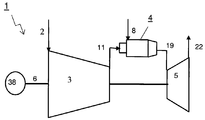
도 1은 압축기, 연속 연소 장치 및 터빈을 갖는 가스 터빈을 도시한다.
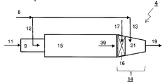
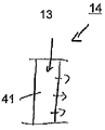
도 2는 제 1 버너, 제 1 연소 챔버, 연료 분사부 및 희석 가스 분사부 뿐 아니라 제 2 연소 구역을 갖는 제 2 연소기를 구비한 연속 연소 장치를 도시한다.
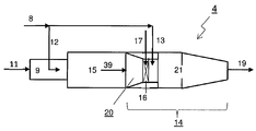
도 3은 제 1 버너, 제 1 연소 챔버, 희석 가스 혼합기를 갖는 제 2 연소기, 제 2 연료 분사부 및 제 2 연소 구역을 갖는 연속 연소 장치를 도시한다.
도 4는 제 1 버너, 제 1 연소 챔버, 희석 가스 혼합기를 갖는 제 2 버너 및 제 2 연소 구역을 갖는 제 2 연소 챔버가 따르는 연료 분사부를 구비한 연속 연소 장치를 갖는 가스 터빈을 도시한다.
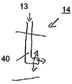
도 5는 제 2 연소기를 위한 다른 연료 및 희석 가스 분사 장치를 도시한다.
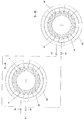
도 6은 제 1 버너의 단면 A-A와 제 1 버너 및 동일 그룹의 연속 연소기의 제 2 연료 분사부 사이에서 연료 분배가 변화될 수 있는 2개의 버너 그룹들을 위한 연료 가스 분배 시스템을 갖는 제 2 연소기의 단면 B-B에 따른 절취도를 도시한다.
도 7은 제 1 버너의 단면 A-A와 한 그룹의 제 1 버너들의 제 1 버너와 이웃 그룹의 연속 연소기들의 제 2 연료 분사부 사이에서 연료 분배가 변화될 수 있는 동일한 크기의 2개의 버너 그룹들을 위한 연료 가스 분배 시스템을 갖는 제 2 연소기의 단면 B-B에 따른 절취도를 도시한다.
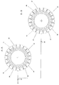
도 8은 제 1 버너의 단면 A-A와 모든 제 1 버너들 및 모든 제 2 연료 분사부들을 위한 연료 가스 분배 시스템의 개별 연료 가스 제어 밸브를 갖는 제 2 연소기의 단면 B-B에 따른 절취도를 도시한다.
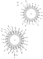
도 9는 제 1 버너의 단면 A-A와 제 1 버너와 각 연속 연소기의 제 2 연료 분사부 사이에 연료 가스를 변화시키도록 배열된 모든 제 1 버너 및 모든 제 2 연료 분사부들을 위한 연료 가스 분배 시스템의 개별 연료 가스 제어 밸브들을 갖는 제 2 연소기의 단면 B-B에 따른 절취도를 도시한다.1 shows a gas turbine having a compressor, a continuous combustion device and a turbine.
Figure 2 shows a continuous combustion device with a first burner, a first combustion chamber, a fuel injector and a diluting gas injector as well as a second combustor with a second combustion zone.
3 shows a continuous combustion device having a first burner, a first combustion chamber, a second combustor with a diluent gas mixer, a second fuel injector and a second combustion zone.
4 shows a gas turbine having a continuous combustion device with a fuel injector along a second combustion chamber having a first burner, a first combustion chamber, a second burner with a dilution gas mixer, and a second combustion zone.
Figure 5 shows another fuel and diluent gas injector for a second combustor.
Figure 6 is a schematic view of a second combustor having a fuel gas distribution system for two burner groups in which the fuel distribution can be varied between the cross section AA of the first burner and the second burner of the same group of continuous burners of the same group And a cut-away view along section BB.
FIG. 7 is a cross-sectional view of one burner group for the same size of burner groups in which the fuel distribution can be varied between the cross section AA of the first burner and the first burner of a group of first burners and the second fuel injection part of a continuous burner of a neighboring group Sectional view along section BB of a second combustor having a fuel gas distribution system.
Figure 8 shows a cut-away view along section BB of a second combustor having a cross-sectional AA of the first burner and an individual fuel gas control valve of the fuel gas distribution system for all first burners and all second fuel injectors.
9 is a cross-sectional view of a fuel gas distribution system for all the first fuel injectors and all first burners arranged to vary the fuel gas between the cross-section AA of the first burner and the second fuel injection portion of each successive combustor, 0.0 > BB < / RTI > of a second combustor having individual fuel gas control valves.
도 1은 연속 연소기 장치(4)를 갖는 가스 터빈(1)을 도시한다. 이는 압축기(3), 연속 연소기 장치(4) 및 터빈(5)을 포함한다.1 shows a
유입 공기(2)는 압축기(3)에 의해서 압축 가스(11)로 압축된다. 연료(8)는 연속 연소기 장치(4)에서 압축 가스와 함께 연소되어서 연소 생성물들(19)을 발생시킨다. 이들은 터빈(6)에서 소모되어서 기계적 작업을 발생시킨다. The inlet air (2) is compressed by the compressor (3) into the compressed gas (11). The
통상적으로, 가스 터빈 시스템은 가스 터빈(1)의 샤프트(6)에 결합되는 발전기(38)를 포함한다. 상기 가스 터빈(1)은 터빈(5) 및 연속 연소기 장치(4)를 위한 냉각 시스템을 포함하고, 이 냉각 시스템은 본 발명의 요지가 아니므로 도시되지 않았다.Typically, the gas turbine system includes a
배기 가스들(22)은 터빈(5)을 떠난다. 잔열은 통상적으로 차후의 수증기 순환에서 사용되고, 이도 역시 본원에서 도시되지 않았다.The exhaust gases (22) leave the turbine (5). The residual heat is typically used in a subsequent water vapor cycle, and this is also not shown here.
연속 연소기 장치(4)의 제 1 예가 도 2에 도시되어 있다. 이 연속 연소기 장치(4)는 압축 가스(11) 및 제 1 연료(12)가 인가되는 제 1 버너(9)를 포함한다. 압축 가스(11) 및 제 1 연료(12)의 혼합물은 제 1 연소 챔버(15)에서 연소되어서 제 1 연소 생성물들(39)을 발생시킨다. 이들은 제 1 연소 챔버의 하류에 배열된 제 2 연소기(14) 안으로 흐른다.A first example of the
캔 아키텍처를 갖는 본 실시예에서, 제 1 연소 챔버(15)는 매끄러운 원통형 유동 경로를 가진다. 제 1 연소 챔버(15)의 원형 단면으로부터 환형의 단면 형상을 갖는 단면 또는 출구 즉, 터빈 입구에서 실제로 직사각형 유동 단면으로의 변이부는 제 2 연소기(14) 안으로 통합된다.In this embodiment having a can architecture, the
제 2 연소기(14)는 희석 가스 분사부(17) 및 제 2 연료 분사부(13)를 포함한다. 제 1 연소 생성물들(39), 희석 가스(17) 및 제 2 연료(13)의 혼합물은 제 2 연소기(14)의 제 2 반응 구역(21)에서 반응하여 연소 생성물들(19)을 형성하고 상기 연소 생성물들은 제 2 연소기(14)를 떠나고 터빈으로 유입된다.The second combustor (14) includes a diluting gas injection part (17) and a second fuel injection part (13). The mixture of the
이 예에서, 제 1 연료(12) 및 제 2 연료(13)는 공통 연료 공급부(8)를 가진다. 그러나, 이들은 또한 다른 연료 유형들을 사용하는 개별 연료 소스들을 가질 수 있다. In this example, the
도 3 및 도 4의 실시예들은 도 2에 기초한다. 도 3에 도시된 예에서, 희석 가스(17) 및 제 1 연소 생성물들(39)은 제 2 연료(13)가 분사되기 전에 희석 가스 혼합기(16)에서 혼합된다.The embodiments of Figures 3 and 4 are based on Figure 2. In the example shown in Figure 3, the
도 4에 도시된 예에서, 제 2 연소기는 제 2 버너(20)를 포함한다. 제 1 연소 생성물들(39)은 상류 단부에 있는 제 2 버너(20)로 인가된다. 희석 가스(17)는 혼합기(16)에서 혼합되고, 상기 혼합기는 제 2 버너(20) 안으로 통합되고 제 2 연료(13)는 제 2 버너(20) 안으로 분사되어서 제 1 연소 생성물들(39), 희석 가스(17) 및 제 2 연료(13)와 혼합된다. 제 2 연료(13)는 또한 혼합기(16)로 인가되어서 혼합기(16)(도시생략)에서 제 1 연소 생성물들(39) 및 희석 가스(17)와 혼합된다.In the example shown in FIG. 4, the second combustor includes a
이 예에서, 출구에서 제 2 버너(20)의 유동 경로의 단면은 화염 안정화를 위해 후속 제 2 반응 구역(21)의 단면보다 작다.In this example, the cross-section of the flow path of the
제 2 연소기를 위한 연료 및 희석 가스 분사 장치들의 다른 예시적인 실시예들은 도 5a 내지 도 5d에 도시되어 있다.Other exemplary embodiments of fuel and diluent gas injectors for a second combustor are shown in Figures 5A-5D.
도 5a는 제 2 연료 분사부(13)를 위한 연료 랜스(fuel lance;40)를 갖는 제 2 연소기(14) 안으로 혼합되는 제 2 연료의 예를 도시한다.5A shows an example of a second fuel mixed into a
도 5b는 제 2 연료 분사부(13)를 위한 플루트 장치(flute arrangement;41)를 갖는 제 2 연소기(14) 안으로 혼합되는 제 2 연료의 예를 도시한다.5B shows an example of a second fuel mixed into a
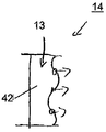
도 5c는 제 2 연료 분사부(13)를 위한 로브형 혼합기(lobed mixer;42)를 갖는 제 2 연소기(14) 안으로 혼합되는 제 2 연료의 예를 도시한다.5C shows an example of a second fuel mixed into a
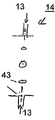
도 5d는 제 2 연료 분사부(13)를 위한 원주방향 분포 측벽 구멍들(43)을 갖는 제 2 연소기(14) 안으로 혼합되는 제 2 연료의 예를 도시한다.5D shows an example of a second fuel mixed into a
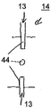
도 5e는 제 2 연료 분사부(13)를 위한 원주방향 분포 측벽 분사 파이프들(44)을 갖는 제 2 연소기(14) 안으로 혼합되는 제 2 연료의 예를 도시한다.5E shows an example of a second fuel mixed into a
모든 예들에서, 희석 가스(17)(도시생략)는 제 2 연료(13)와 함께 분사될 수 있다.In all examples, a diluent gas 17 (not shown) may be injected with the
연료 가스 분배 시스템의 다른 예시적인 실시예들의 상세 사항은 도 6 내지 도 10에 도시된다.Details of other exemplary embodiments of the fuel gas distribution system are shown in Figures 6-10.
도 6은 제 1 버너에서 도 2의 A-A 단면과 예시적인 연료 분배 시스템을 갖는 제 2 연소기에 따른 도 2의 B-B 단면을 도시한다.Figure 6 shows a cross section taken along the line A-A in Figure 2 in a first burner and a cross section B-B in Figure 2 in accordance with a second combustor having an exemplary fuel delivery system.
연료(8)는 주요 연료 라인을 통하여 공급되고 제 1의 제 1 버너 그룹 주요 연료링(25)을 위한 공급 라인과 제 2의 제 1 버너 그룹 주요 연료링(26)을 위한 공급 라인으로 분기된다. 제 1의 제 1 버너 그룹 연료 제어 밸브(23)는 제 1의 제 1 버너 그룹 주요 연료링(25)에 대한 연료 라인에 배열되고 제 2의 제 1 버너 그룹 연료 제어 밸브(24)는 제 2의 제 1 버너 그룹 주요 연료링(26)에 대한 연료 라인에 배열된다. 각각의 제 1 버너(9)는 연료 공급부(10)를 통하여 주요 연료링(25,26)으로부터 연료가 공급된다. 도시된 예에서, 절반의 버너들(9)은 제 1의 제 1 버너 그룹 주요 연료링(25)에 연결되고 다른 절반의 버너들(9)은 제 2의 제 1 버너 그룹 주요 연료링(26)에 연결된다. 버너들은 제 1의 각각의 제 2의 제 1 버너 그룹 주요 연료링(25, 26)에 교대로 연결될 수 있다. 이 예에서, 일부 버너들은 2개의 주요 연료링(25,26)에 교대로 연결되고 일부는 쌍 배열로 연결되며, 이는 진동을 완화시키는데 유리할 수 있다.The
제 1의 제 1 버너 그룹 연료 제어 밸브(23)의 하류에 있는 연료 라인은 제 1 연속 그룹 주요 연료링(31)으로 분기되고 제 2의 제 1 버너 그룹 연료 제어 밸브(24)의 하류에 있는 연료 라인은 제 2 연속 그룹 주요 연료링(32)으로 분기된다.The fuel line downstream of the first first burner group
제 1 연속 그룹 연료 제어 밸브(33)는 제 1 연속 그룹 주요 연료링(31)에 대한 연료 라인에 배열되고 제 2 연속 그룹 연료 제어 밸브(34)는 제 2 연속 그룹 주요 연료링(32)에 대한 연료 라인에 배열된다. 각각의 제 2 연소기(14)에는 연료 공급부(10)를 통하여 연속 그룹 주요 연료링(31,32)으로부터 연료가 공급된다.The first continuous group
제 1 연속 그룹의 제 2 연소기들(14)은 연속 연소기 장치의 제 1의 제 1 버너 그룹의 제 1 연소기(9)의 하류에 배열된다. 제 2 연속 그룹 제어 밸브(34)를 개방할 때, 연료는 제 1의 제 1 버너 그룹으로부터 제 1의 연속 그룹의 제 2 연소기들(14)로 이동한다. 유사하게, 제 1 연속 그룹 제어 밸브(33)를 개방할 때, 연료는 제 2의 제 1 버너 그룹으로부터 제 2의 연속 그룹의 제 2 연소기들로 이동한다.The
도 7은 도 6에 기초하지만, 제 1의 제 1 버너 그룹 연료 제어 밸브(23)는 제 2의 제 1 버너 그룹 주요 연료링(26)에 대한 연료 라인의 분기부의 상류에 배열된다; 따라서, 제 1의 제 1 버너 그룹 연료 제어 밸브(23)는 전체 연료(8) 유동을 효과적으로 제어한다.Although FIG. 7 is based on FIG. 6, the first first burner group
또한, 도 7의 예는 제 1 연속 그룹 주요 연료링(31)에 대한 연료 라인이 제 2의 제 1 버너 그룹 연료 제어 밸브(24)의 하류에서 분기된다는 점과, 제 2 연속 그룹 주요 연료링(32)에 대한 연료 라인이 제 1 버너 그룹 연료 제어 밸브(23)와 제 2의 제 1 버너 그룹 연료 제어 밸브(24) 사이에서 분기된다는 점에서 상이하다.7 also shows that the fuel line for the first continuous group
제 2 연속 그룹 제어 밸브(34)를 개방할 때, 연료는 제 1의 제 1 버너 그룹에서 제 2의 연속 그룹의 제 2 연소기들로 이동한다. 유사하게, 제 1 연속 그룹 연료 제어 밸브(33)를 개방할 때, 연료는 제 2의 제 1 버너 그룹에서 제 1의 연속 그룹의 제 2 연소기들로 이동한다. When opening the second continuous
도 8은 제 1 버너를 절취한 도 2의 A-A 단면과 도 2의 제 2 연소기를 절취한 B-B 단면에서 연료 분배 시스템을 위한 다른 예를 도시한다.Fig. 8 shows another example for a fuel distribution system at section A-A in Fig. 2 with the first burner cut out and section B-B at the second combustor cut out in Fig.
연료(8)는 주요 연료 라인을 통하여 공급되고 전체 연료 유동은 주요 연료 제어 밸브(27)에 의해서 제어된다. 연료 라인은 제 1 버너 주요 연료링(30)에 대한 공급 라인과 제 2 연료 분사부 주요 연료링(35)에 대한 공급 라인으로 분기된다.The
제 1 버너 주요 연료링(30)으로부터 각각의 제 1 버너(9)에는 연료 공급부(10)와 단일 제 1 버너 연료 제어 밸브(36)를 경유하여 연료가 공급된다.Fuel is supplied to the respective
제 2 연료 분사부 주요 연료링(35)으로부터 각각의 제 2 연소기(14)에는 연료 공급부(10)와 단일 분사기 연료 제어 밸브(37)를 경유하여 연료가 공급된다.Fuel is supplied to the respective
이 장치는 각각의 제 1 버너(9)와 각각의 제 2 연소기(14)에 대한 개별적인 유동 제어를 허용한다. 그에 의해서, 유동은 제 1 버너들(9)에서 제 2 연소기들로 그리고 제 1 버너들(9) 사이에서 그리고 제 2 연소기들(14) 사이에서 임의의 원하는 작동 개념을 따라서 이동할 수 있다.This arrangement allows for separate flow control for each
도시된 바와 같이, 제 2 연료 제어 밸브(28)는 제 2 연료 분사부 주요 연료링(35)에 대한 공급 라인의 연료 라인에 배열되어서 제 1 버너들(9)과 제 2 연소기들(14) 사이의 전체 연료 분할을 제어할 수 있다. 그러나, 이는 또한 다른 실시예에서 생략될 수 있다. As shown, the second
도 9는 도 8에 기초하지만, 제 2 연료 분사부 주요 연료링(35)이 없고 이로 분기된 공급 라인이 없으며 제 2 연료 제어 밸브(28)가 없다. Although FIG. 9 is based on FIG. 8, there is no secondary fuel injection
본 예에서, 각각의 제 2 연소기(14)는 단일 제 1 버너 연료 제어 밸브(26)의 하류에 있는 제 1 버너(9)의 연료 공급부(10)로부터 분기되는 개별 연료 공급 라인(a,b,c,,,,t)에 의해서 공급된다.In this example, each
이 장치는 각각의 제 1 버너(9)에 대한 그리고 각각의 제 2 연소기(14)에 대한 개별 유동 제어가 허용된다. 그에 의해서, 유동은 제 1 버너들(9)에서 제 2 연소기들로 그리고 제 1 버너들(9) 사이에서 그리고 제 2 연소기들(14) 사이에서 임의의 바람직한 작동 개념을 따라 이동할 수 있다. 각각의 제 2 연소기(14)의 연료 공급은 각각의 단일 제 1 버너 연료 제어 밸브(36)의 하류에 있는 상류 버너(9)의 연료 공급부(10)로부터 분기되기 때문에, 연료 유동은 전체 연료(8) 유동에 대한 충격없이 실제로 하류에서 제 1 버너(9)에서 제 2 연소기(14)로 이동할 수 있다.This arrangement allows for individual flow control for each
모든 도시된 장치에 대해서, 캔 또는 환형 아키텍처들 또는 2개의 조합이 가능하다.For all illustrated devices, can or annular architectures or a combination of the two is possible.
모든 설명된 장점들은 특정 조합들에 국한되지 않고 또한 본 발명의 범주 내에서 단독으로 또는 조합으로 사용될 수 있다. 예를 들어, 부분 부하 작동에서 개별 연속 연소기들(7) 즉, 제 1 버너(9) 및 제 2 연소기(14) 또는 연속 연소기들(7)의 그룹들을 비작동 상태로 하기 위하여 다른 가능성들도 선택적으로 예상할 수 있다. 또한, 희석 가스(17)는 희석 가스로서 사용되기 전에 냉각 가스 냉각기에서 재냉각될 수 있다.All described advantages are not limited to specific combinations and may also be used alone or in combination within the scope of the present invention. For example, in order to put the individual continuous combustors 7, i.e., the
1. 가스 터빈
2. 유입 공기
3. 압축기
4. 연속 연소기 장치
5. 터빈
6. 샤프트
7. 연속 연소기
8. 연료
9. 제 1 버너
10. 연료 공급부
11. 압축 가스
12. 제 1 연료
13. 제 2 연료
14. 제 2 연소기
15. 제 1 연소 챔버
16. 혼합기
17. 희석 공기
18. 제 2 버너
19. 연소 생성물들
20. 제 2 버너
21. 제 2 반응 구역
22. 배기 가스
23. 제 1의 제 1 버너 그룹 연료 제어 밸브
24. 제 2의 제 1 버너 그룹 연료 제어 밸브
25. 제 1의 제 1 버너 그룹 주요 연료링
26. 제 2의 제 1 버너 그룹 주요 연료링
27. 주요 연료 제어 밸브
28. 제 2 연료 제어 밸브
29. 연료 공급부
30. 제 1 버너 주요 연료링
31. 제 1 연속 그룹 주요 연료링
32. 제 2 연속 그룹 주요 연료링
33. 제 1 연속 그룹 연료 제어 밸브
34. 제 2 연속 그룹 제어 밸브
35. 제 2 연료 분사부 주요 연료링
36. 단일 제 1 버너 연료 제어 밸브
37. 단일 분사기 연료 제어 밸브
38. 발전기
39. 제 1 연소 생성물들
40. 연료 랜스
41. 플루트
42. 로브형 혼합기
43. 벽식 전체 혼합기
44. 벽식 분사부 파이프들
a,b,c,,,,t. 단일 제 2 분사기 연료 라인들1. Gas Turbine
2. Inlet air
3. Compressor
4. Continuous burner unit
5. Turbines
6. Shaft
7. Continuous combustor
8. Fuel
9. First Burner
10. Fuel supply section
11. Compressed gas
12. First fuel
13. Second fuel
14. Second combustor
15. First combustion chamber
16. Mixer
17. Dilution air
18. The second burner
19. Combustion products
20. The second burner
21. Second reaction zone
22. Exhaust gas
23. The first first burner group fuel control valve
24. The second first burner group fuel control valve
25. First primary burner group main fuel ring
26. Second First Burner Group Main Fuel Ring
27. Main fuel control valve
28. Second fuel control valve
29. Fuel supply section
30. First burner main fuel ring
31. First Continuous Group Main Fuel Ring
32. Second consecutive group main fuel ring
33. First Continuous Group Fuel Control Valve
34. Second continuous group control valve
35. Second fuel injection part main fuel ring
36. A single first burner fuel control valve
37. Single injector fuel control valve
38. Generator
39. First combustion products
40. Fuel lance
41. Flute
42. Lobed mixer
43. Wall full mixer
44. Wall-mounted spray pipes
a, b, c ,,,, t. Single second injector fuel lines
Claims (15)
각각의 연속 연소기(7)가 유체 유동 연결부에서 연속적으로 배열된 제 1 버너(9), 제 1 연소 챔버(15), 및 제 2 연소기(14)를 포함하는, 가스 터빈(1)의 작동 방법으로서, 상기 방법은
- 상기 압축기(3)에서 유입 가스를 압축하는 단계,
- 상기 연속 연소기(7)의 제 1 버너들(9)에서 제 1 연료(12)를 혼합하는 단계,
- 제 1 연소 생성물들(39)을 얻기 위하여 상기 제 1 연소 챔버(15)에서 제 1 연료(12)와 압축 가스(11)의 혼합물을 연소시키는 단계로서, 낮은 상대 부하에서, 추가 연료가 상기 제 1 버너(9)의 하류에 있는 상기 연속 연소기(7) 안으로 더 이상 분사되지 않고 그리고 높은 상대 부하에서 제 2 연료(13)가 상기 제 1 연소 챔버(15)의 하류에 있는 상기 연속 연소기(7) 안으로 분사되는, 상기 연소 단계,
- 제 2 연소기 연소 생성물들(19)을 얻기 위하여 상기 제 1 연소 생성물들(39)과 상기 제 2 연료(13)의 혼합물을 연소시키고, 상기 터빈(5)에서 상기 제 2 연소기 연소 생성물들(19)을 팽창시키는 단계를 포함하는, 상기 가스 터빈(1)의 작동 방법에 있어서,
상기 가스 터빈(1)의 부분 부하 작동 중에, 상기 제 2 연료(13)의 연료 유입을 개시할 때, 상기 제 2 연료 유동은 최소 유동으로 증가하고, 상기 동일 연속 연소기(7)의 제 1 버너(9)에 대한 제 1 연료(12) 유동 및/또는 상기 연속 연소기 장치(4)의 적어도 하나의 다른 연속 연소기(7)에 대한 상기 연료(8) 유동은 상기 가스 터빈(1)에 대한 상기 전체 연료(8) 질량 유동을 실질적으로 일정하게 유지하도록 감소되는 것을 특징으로 하는 가스 터빈의 작동 방법.A continuous combustor arrangement (4) having at least one compressor (3), a plurality of continuous combustors (7), and a turbine (5) downstream of said continuous combustor arrangement (4)
A method of operating a gas turbine (1), wherein each continuous combustor (7) comprises a first burner (9), a first combustion chamber (15) and a second combustor (14) , The method comprising:
- compressing the incoming gas in the compressor (3)
- mixing the first fuel (12) in the first burners (9) of the continuous combustor (7)
- combusting a mixture of the first fuel (12) and the compressed gas (11) in the first combustion chamber (15) to obtain first combustion products (39) Wherein the second fuel 13 is no longer injected into the continuous combustor 7 downstream of the first burner 9 and at a higher relative load than the continuous combustor 15 downstream of the first combustion chamber 15 7), said combustion step,
- combusting a mixture of said first combustion products (39) and said second fuel (13) to obtain second combustor combustion products (19) and causing said second combustor combustion products 19. A method of operating the gas turbine (1), comprising the steps of:
During partial load operation of the gas turbine (1), when initiating fuel entry of the second fuel (13), the second fuel flow increases to a minimum flow, and the first burner The flow of the first fuel 12 to the gas turbine 9 and / or the flow of the fuel 8 to at least one other continuous combustor 7 of the continuous combustor device 4 is controlled by the above- Is reduced to maintain a substantially constant mass flow of total fuel (8).
상기 제 1 연소기 연소 생성물들(37) 및 상기 제 2 연료(13)의 혼합물을 연소시키기 전에, 희석 가스(17)가 상기 제 1 연소기 연소 생성물들(37)에 혼합되는 것을 특징으로 하는 가스 터빈의 작동 방법.The method according to claim 1,
Characterized in that a dilution gas (17) is mixed with said first combustor combustion products (37) before combustion of said mixture of said first combustor combustion products (37) and said second fuel (13) Lt; / RTI >
상기 제 2 연료(13) 유동이 개시되는, 상기 동일한 연속 연소기(7)의 상류에 있는 상기 제 1 버너(9)에 대한 상기 제 1 연료(12) 유동은 감소되는 것을 특징으로 하는 가스 터빈의 작동 방법.The method according to claim 1,
Characterized in that the flow of the first fuel (12) to the first burner (9) upstream of the same continuous combustor (7) in which the flow of the second fuel (13) is started is reduced How it works.
제 2 연료 유동이 개시되는, 상기 연속 연소기(7)의 적어도 하나의 이웃 연속 연소기(7)에 대한 상기 제 1 연료(12) 유동은 감소되는 것을 특징으로 하는 가스 터빈의 작동 방법.The method according to claim 1,
Characterized in that the flow of the first fuel (12) to at least one neighboring continuous combustor (7) of the continuous combustor (7) in which the second fuel flow is initiated is reduced.
복수의 연속 연소기들(7)에 대한 상기 제 2 연료(13) 유동은 동시에 개시되는 것을 특징으로 하는 가스 터빈의 작동 방법.The method according to claim 1,
Characterized in that the second fuel (13) flow to the plurality of continuous combustors (7) is started simultaneously.
상기 연속 연소기 장치(4)의 모든 상기 연속 연소기들(7)에 대한 상기 제 2 연료(13) 유동은 동시에 개시되고 상기 연속 연소기 장치(4)의 모든 상기 제 1 버너들(9)에 대한 상기 제 1 연료(12) 유동은 동시에 감소되는 것을 특징으로 하는 가스 터빈의 작동 방법.The method according to claim 1,
The flow of the second fuel (13) to all the continuous combustors (7) of the continuous combustor device (4) is started simultaneously and the flow of the second fuel (13) to all the first burners Wherein the flow of the first fuel (12) is reduced at the same time.
상기 연속 연소기들(7)에 대한 상기 제 2 연료 유동(13)은, 상기 가스 터빈 부하, 상기 부하를 표시하는 온도, 및 상기 부하를 표시하는 압력 중 적어도 하나의 함수로서, 개별 연속 연소기들(4)에 대해서 연속적으로 개시되거나 또는 상기 연속 연소기들(7)의 그룹들에 대해서 개시되는 것을 특징으로 하는 가스 터빈의 작동 방법.The method according to claim 1,
Wherein the second fuel flow (13) for the continuous combustors (7) is a function of at least one of the gas turbine load, the temperature indicative of the load, and the pressure indicative of the load, 4) or is started for the groups of said continuous combustors (7).
상기 제 2 연료(13) 유동의 개시 시에 감소되는, 상기 동일한 연속 연소기(7)의 제 1 버너(9)에 대한 상기 제 1 연료(12) 유동 및/또는 적어도 하나의 다른 연속 연소기(7)에 대한 상기 연료 유동은 상기 제 2 연료(13) 유동의 개시 전에 상기 연료 유동으로 다시 증가하고, 그후 상기 이웃 연속 연소기(7) 또는 상기 연속 연소기들(7)의 이웃 그룹에 대한 상기 제 2 연료(13) 유동을 개시하는 것을 특징으로 하는 가스 터빈의 작동 방법.8. The method of claim 7,
(12) flow to the first burner (9) of the same continuous combustor (7) and / or at least one other continuous combustor (7) which is reduced at the start of the second fuel ) Is increased again to the fuel flow prior to the start of the second fuel (13) flow, and thereafter, the fuel flow to the second group of adjacent combustors (7) or adjacent combustors (7) Fuel (13) flow. ≪ / RTI >
상기 제 2 연료(13) 유동은 상기 동일한 연속 연소기 장치의 제 1 버너(9)에 대한 상기 연료 유동(12) 이후에 상기 최소 유동 초과로 증가하고, 그리고/또는 상기 제 2 연료(13) 유동의 개시 시에 감소된 적어도 하나의 다른 연속 챔버(7)에 대한 상기 연료 유동은 상기 가스 터빈의 부하를 제어하기 위하여 상기 제 2 연료(13) 유동의 개시 전에 상기 연료(8) 유동으로 다시 증가하는 것을 특징으로 하는 가스 터빈의 작동 방법.9. The method according to any one of claims 6 to 8,
The flow of the second fuel 13 increases beyond the minimum flow after the fuel flow 12 to the first burner 9 of the same continuous combustor arrangement and / The fuel flow to at least one other continuous chamber 7 reduced at the start of the second fuel 13 is increased again to the fuel 8 flow prior to the start of the second fuel 13 flow to control the load of the gas turbine Wherein the gas turbine is a gas turbine.
상기 제 2 연료(13) 분사부의 스위치 오프는 반대 순서로 실행되는 것을 특징으로 하는 가스 터빈의 작동 방법.10. The method according to any one of claims 1 to 9,
Wherein switching off of the injecting portion of the second fuel (13) is carried out in the reverse order.
모든 제 1 버너들(9) 및 제 2 연료 분사부들(13)이 작동한 후에, 적어도 하나의 제 1 버너(9)에 대한 상기 연료 유동은 상기 연속 연소기 장치(4)의 적어도 다른 제 1 버너(9)에 대한 상기 연료 유동 초과로 증가하고 그 제 1 버너(9)에 대한 증가된 연료 유동과 함께 상기 연속 연소기의 제 2 연료 분사부(13)에 대한 상기 연료 유동은 상기 연속 연소기 장치(4)의 적어도 다른 제 2 연료 분사부(13)에 대한 상기 연료 유동과 비교할 때 감소되어서 상기 연속 연소기(7)에 대한 전체 연료 유동은 불변상태로 유지되는 것을 특징으로 하는 가스 터빈의 작동 방법.11. The method according to any one of claims 1 to 10,
After all of the first burners 9 and the second fuel injectors 13 have operated, the fuel flow to at least one first burner 9 is directed to the at least one other first burner 9 of the continuous combustor device 4, (9) and the fuel flow to the second fuel injector (13) of the continuous combustor with an increased fuel flow to the first burner (9) is increased by the continuous combustor device 4) is reduced as compared to said fuel flow to at least the other second fuel injection part (13) so that the total fuel flow to said continuous combustor (7) remains unchanged.
각각의 연속 연소기(7)는 제 1 연료 분사부(12)를 갖는 제 1 버너(9), 제 1 연소 챔버(15), 제 2 연료 분사부(13)를 갖는 제 2 연소기(14), 유체 유동 연결부에 연속적으로 배열된 제 2 반응 구역(21), 및 연료를 상기 제 1 연료 분사부(12)와 상기 제 2 연료 분사부(13)에 공급하기 위한 연료 분배 시스템을 포함하고, 상기 연료 분배 시스템은 연료 제어 밸브(23,24,27)와, 연료를 상기 제 1 연료 분사부(12)로 공급하기 위한 주요 연료링(30,25,26)을 포함하는, 상기 가스 터빈(1)에 있어서,
상기 제 2 연료 분사부(13)에 대한 적어도 하나의 공급 라인은 연료를 상기 제 1 연료 분사부(12)로 공급하기 위한 상기 연료 제어 밸브(23,24,27,36)의 하류에서 분기되고, 상기 제 2 연료 분사부(13)에 대한 상기 공급 라인에는 제 2 연료 제어 밸브(28,33,34,38)가 배열되는 것을 특징으로 하는 가스 터빈.A gas turbine (1) comprising at least one compressor (3), a continuous combustor device (4) having a plurality of continuous combustors (7), and a turbine (5) downstream of said continuous combustor device ,
Each continuous combustor 7 includes a first burner 9 having a first fuel injection portion 12, a first combustion chamber 15, a second combustor 14 having a second fuel injection portion 13, A second reaction zone (21) continuously arranged in fluid flow connection, and a fuel distribution system for supplying fuel to said first fuel injection part (12) and said second fuel injection part (13) The fuel distribution system comprises a fuel control valve (23, 24, 27) and a main fuel ring (30, 25, 26) for supplying fuel to the first fuel injection part (12) ),
At least one supply line to the second fuel injection part (13) branches downstream of the fuel control valve (23, 24, 27, 36) for supplying fuel to the first fuel injection part , And a second fuel control valve (28, 33, 34, 38) is arranged in the supply line to the second fuel injection part (13).
상기 연속 연소기 장치(4)는
제 1의 제 1 버너 그룹 주요 연료링(25)에 연결된 제 1 그룹의 제 1 버너들(9),
제 2의 제 1 버너 그룹 주요 연료링(26)에 연결된 제 2 그룹의 제 1 버너들(9),
제 1 연속 그룹 주요 연료링(31)에 연결된 제 1 그룹의 제 2 연료 분사기들(13),
제 2 연속 그룹 주요 연료링(32)에 연결된 제 2 그룹의 제 2 연료 분사기들(13)을 포함하고,
제 1 버너 그룹의 연료 제어 밸브(23)는 상기 제 1의 제 1 버너 그룹 주요 연료링(25)에 대한 공급 라인에 배열되고,
제 2 버너 그룹의 연료 제어 밸브(24)는 상기 제 2의 제 1 버너 그룹 주요 연료링(26)에 대한 공급 라인에 배열되고,
상기 제 1 연속 그룹 주요 연료링(31)에 대한 공급 라인은 상기 제 1의 제 1 버너 그룹의 연료 제어 밸브(23)의 하류에서 분기되고, 제 1 연속 그룹 연료 제어 밸브(33)는 상기 분기 라인에 배열되며,
상기 제 2 연속 그룹 주요 연료링(32)에 대한 공급 라인은 상기 제 2의 제 1 버너 그룹의 연료 제어 밸브(24)의 하류에 분기되고, 제 2 연속 그룹 연료 제어 밸브(34)는 상기 분기 라인에 배열되며,
상기 제 1 그룹의 제 2 연료 분사기들(13)의 각각의 제 2 연료 분사기(13)는 하나의 연속 연소기(7)에서 상기 제 1 그룹의 제 1 버너들(9)의 하나의 제 1 버너(9)의 하류에 배열되는 것을 특징으로 하는 가스 터빈.13. The method of claim 12,
The continuous combustor arrangement (4)
A first group of first burners 9 connected to a first primary burner group main fuel ring 25,
A second group of first burners 9 connected to a second first burner group main fuel ring 26,
A first group of second fuel injectors 13 connected to the first continuous group main fuel ring 31,
And a second group of second fuel injectors (13) connected to a second continuous group main fuel ring (32)
The fuel control valve 23 of the first burner group is arranged in the supply line to the first first burner group main fuel ring 25,
The fuel control valve 24 of the second burner group is arranged in the supply line to the second first burner group main fuel ring 26,
The supply line for the first continuous group main fuel ring 31 is branched downstream of the fuel control valve 23 of the first first burner group and the first continuous group fuel control valve 33 is branched Lt; / RTI >
The supply line for the second continuous group main fuel ring 32 is branched downstream of the fuel control valve 24 of the second first burner group and the second continuous group fuel control valve 34 is branched for the branch Lt; / RTI >
Each of the second fuel injectors 13 of the first group of second fuel injectors 13 is connected to one of the first burners 9 of the first group of first burners 9 in one continuous combustor 7, Is arranged downstream of the gas turbine (9).
상기 연속 연소기 장치(4)는
제 1의 제 1 버너 그룹 주요 연료링(25)에 연결된 제 1 그룹의 제 1 버너들(9),
제 2의 제 1 버너 그룹 주요 연료링(26)에 연결된 제 2 그룹의 제 1 버너들(9),
제 1 연속 그룹 주요 연료링(31)에 연결된 제 1 그룹의 제 2 연료 분사기들(13),
제 2 연속 그룹 주요 연료링(32)에 연결된 제 2 그룹의 제 2 연료 분사기들(13)을 포함하고,
제 1 버너 그룹의 연료 제어 밸브(23)는 상기 제 1의 제 1 버너 그룹 주요 연료링(25)에 대한 공급 라인에 배열되고,
제 2 버너 그룹의 연료 제어 밸브(24)는 상기 제 2의 제 1 버너 그룹 주요 연료링(26)에 대한 공급 라인에 배열되고,
상기 제 1 연속 그룹 주요 연료링(31)에 대한 공급 라인은 상기 제 1의 제 1 버너 그룹의 연료 제어 밸브(23)의 하류에서 분기되고, 제 1 연속 그룹 연료 제어 밸브(33)는 상기 분기 라인에 배열되며,
상기 제 2 연속 그룹 주요 연료링(32)에 대한 공급 라인은 상기 제 2의 제 1 버너 그룹의 연료 제어 밸브(24)의 하류에서 분기되고, 제 2 연속 그룹 연료 제어 밸브(34)는 상기 분기 라인에 배열되며,
상기 제 1 그룹의 제 2 연료 분사기들(13)의 각각의 제 2 연료 분사기(13)는 하나의 연속 연소기(7)에서 상기 제 2 그룹의 제 1 버너들(9)의 하나의 제 1 버너(9)의 하류에 배열되는 것을 특징으로 하는 가스 터빈.13. The method of claim 12,
The continuous combustor arrangement (4)
A first group of first burners 9 connected to a first primary burner group main fuel ring 25,
A second group of first burners 9 connected to a second first burner group main fuel ring 26,
A first group of second fuel injectors 13 connected to the first continuous group main fuel ring 31,
And a second group of second fuel injectors (13) connected to a second continuous group main fuel ring (32)
The fuel control valve 23 of the first burner group is arranged in the supply line to the first first burner group main fuel ring 25,
The fuel control valve 24 of the second burner group is arranged in the supply line to the second first burner group main fuel ring 26,
The supply line for the first continuous group main fuel ring 31 is branched downstream of the fuel control valve 23 of the first first burner group and the first continuous group fuel control valve 33 is branched Lt; / RTI >
The supply line for the second continuous group main fuel ring 32 is branched downstream of the fuel control valve 24 of the second first burner group and the second continuous group fuel control valve 34 is branched Lt; / RTI >
Each of the second fuel injectors 13 of the first group of second fuel injectors 13 is connected to one of the first burners 9 of the second group of first burners 9 in one continuous combustor 7, Is arranged downstream of the gas turbine (9).
상기 연속 연소기 장치(4)의 각각의 제 2 연료 분사기(12)는 단일 분사기 연료 제어 밸브(38)를 구비한 연료 공급부(10)를 갖는 상기 연료 제어 밸브(23,24,25,37)의 하류에서 분기된 공급 라인에 연결되는 것을 특징으로 하는 가스 터빈.13. The method of claim 12,
Each of the second fuel injectors 12 of the continuous combustor arrangement 4 is connected to the fuel control valve 23,24,25,37 having a fuel supply 10 with a single injector fuel control valve 38, And connected to a downstream feed line.
Applications Claiming Priority (2)
| Application Number | Priority Date | Filing Date | Title |
|---|---|---|---|
| EP13186852.3A EP2857658A1 (en) | 2013-10-01 | 2013-10-01 | Gas turbine with sequential combustion arrangement |
| EP13186852.3 | 2013-10-01 |
Publications (1)
| Publication Number | Publication Date |
|---|---|
| KR20150039107A true KR20150039107A (en) | 2015-04-09 |
Family
ID=49303782
Family Applications (1)
| Application Number | Title | Priority Date | Filing Date |
|---|---|---|---|
| KR20140130831A KR20150039107A (en) | 2013-10-01 | 2014-09-30 | Gas turbine with sequential combustion arrangement |
Country Status (8)
| Country | Link |
|---|---|
| US (2) | US9708983B2 (en) |
| EP (1) | EP2857658A1 (en) |
| JP (1) | JP2015072114A (en) |
| KR (1) | KR20150039107A (en) |
| CN (1) | CN104633711A (en) |
| CA (1) | CA2865729A1 (en) |
| IN (1) | IN2014DE02753A (en) |
| RU (1) | RU2014138247A (en) |
Families Citing this family (15)
| Publication number | Priority date | Publication date | Assignee | Title |
|---|---|---|---|---|
| EP3101342B1 (en) * | 2015-06-02 | 2020-04-29 | Ansaldo Energia IP UK Limited | Method and system for operating a combustion device |
| FR3037384B1 (en) * | 2015-06-11 | 2017-06-23 | Turbomeca | TURBOMACHINE HVAC COMBUSTION CHAMBER MODULE COMPRISING A COMBUSTION CHAMBER |
| EP3135880B1 (en) * | 2015-08-25 | 2020-07-08 | Ansaldo Energia IP UK Limited | Gas turbine with a sequential combustion arrangement and fuel composition control |
| EP3228939B1 (en) * | 2016-04-08 | 2020-08-05 | Ansaldo Energia Switzerland AG | Method for combusting a fuel, and combustion appliance |
| EP3421761B1 (en) * | 2017-06-30 | 2020-11-25 | Ansaldo Energia IP UK Limited | Second-stage combustor for a sequential combustor of a gas turbine |
| RU2747655C2 (en) * | 2017-11-17 | 2021-05-11 | Ансальдо Энергия Свитзерленд Аг | Reheat burner for gas turbine and gas turbine containing such reheat burner |
| FR3076320B1 (en) * | 2017-12-28 | 2020-02-07 | Safran Aircraft Engines | METHOD FOR CONTROLLING THE FUEL SUPPLY OF A COMBUSTION CHAMBER OF A TURBOMACHINE, FUEL SUPPLY SYSTEM AND TURBOMACHINE |
| US11085321B2 (en) * | 2018-01-30 | 2021-08-10 | Honeywell International Inc. | Bleed air compensated continuous power assurance analysis system and method |
| EP3524799A1 (en) * | 2018-02-13 | 2019-08-14 | Siemens Aktiengesellschaft | Method for operating a burner assembly of a gas turbine |
| US11156164B2 (en) | 2019-05-21 | 2021-10-26 | General Electric Company | System and method for high frequency accoustic dampers with caps |
| US11174792B2 (en) | 2019-05-21 | 2021-11-16 | General Electric Company | System and method for high frequency acoustic dampers with baffles |
| JP7231493B2 (en) | 2019-06-12 | 2023-03-01 | 三菱重工業株式会社 | Control device, gas turbine, control method and program |
| EP3822469B1 (en) * | 2019-11-18 | 2023-01-04 | Ansaldo Energia Switzerland AG | Gas turbine engine with alternating patterns of active burners and method of controlling a gas turbine engine |
| EP4019844B1 (en) * | 2020-12-24 | 2024-04-03 | Ansaldo Energia Switzerland AG | Gas turbine engine with first and second stage fuel control and method of controlling a gas turbine engine |
| EP4343131A1 (en) * | 2022-09-23 | 2024-03-27 | General Electric Technology GmbH | Method for operating a combustion system, combustion system and gas turbine engine comprising the combustion system |
Family Cites Families (24)
| Publication number | Priority date | Publication date | Assignee | Title |
|---|---|---|---|---|
| JPS6057131A (en) * | 1983-09-08 | 1985-04-02 | Hitachi Ltd | Fuel feeding process for gas turbine combustor |
| JPS61110817A (en) * | 1984-11-01 | 1986-05-29 | Toshiba Corp | Combustion device |
| JPS61241425A (en) * | 1985-04-17 | 1986-10-27 | Hitachi Ltd | Fuel gas controlling method of gas turbine and controller |
| JPS6267240A (en) * | 1985-09-20 | 1987-03-26 | Hitachi Ltd | Fuel converting method for burner |
| US4735052A (en) * | 1985-09-30 | 1988-04-05 | Kabushiki Kaisha Toshiba | Gas turbine apparatus |
| JPS62174539A (en) * | 1985-09-30 | 1987-07-31 | Toshiba Corp | Gas turbine controller |
| CH674561A5 (en) | 1987-12-21 | 1990-06-15 | Bbc Brown Boveri & Cie | |
| JP2543981B2 (en) * | 1989-05-23 | 1996-10-16 | 株式会社東芝 | Gas turbine combustor |
| FR2672667B1 (en) * | 1991-02-13 | 1994-12-09 | Snecma | COMBUSTION CHAMBER FOR A TURBOJECTOR WITH LOW LEVEL OF POLLUTANT EMISSIONS. |
| US5226287A (en) * | 1991-07-19 | 1993-07-13 | General Electric Company | Compressor stall recovery apparatus |
| JP2758301B2 (en) * | 1991-11-29 | 1998-05-28 | 株式会社東芝 | Gas turbine combustor |
| JPH06307260A (en) * | 1993-04-26 | 1994-11-01 | Toshiba Corp | Gas turbine controller |
| JP2950720B2 (en) * | 1994-02-24 | 1999-09-20 | 株式会社東芝 | Gas turbine combustion device and combustion control method therefor |
| DE19547913A1 (en) | 1995-12-21 | 1997-06-26 | Abb Research Ltd | Burners for a heat generator |
| DE19944922A1 (en) * | 1999-09-20 | 2001-03-22 | Asea Brown Boveri | Control of primary measures to reduce thermal nitrogen oxide formation in gas turbines |
| US20030150216A1 (en) * | 2001-07-03 | 2003-08-14 | O'beck John Timothy | Gas turbine |
| DE10312971B4 (en) | 2003-03-24 | 2017-04-06 | General Electric Technology Gmbh | Method for operating a gas turbine group |
| US6935116B2 (en) | 2003-04-28 | 2005-08-30 | Power Systems Mfg., Llc | Flamesheet combustor |
| GB0323255D0 (en) * | 2003-10-04 | 2003-11-05 | Rolls Royce Plc | Method and system for controlling fuel supply in a combustion turbine engine |
| ES2551506T3 (en) * | 2006-06-07 | 2015-11-19 | Alstom Technology Ltd | Procedure for the operation of a gas turbine and combined power plant for carrying out the procedure |
| EP2071156B1 (en) * | 2007-12-10 | 2013-11-06 | Alstom Technology Ltd | Fuel distribution system for a gas turbine with multistage burner arrangement |
| CH700796A1 (en) * | 2009-04-01 | 2010-10-15 | Alstom Technology Ltd | Method for CO-emission operation of a gas turbine with sequential combustion and gas turbine with improved part-load emission behavior. |
| US8418468B2 (en) * | 2010-04-06 | 2013-04-16 | General Electric Company | Segmented annular ring-manifold quaternary fuel distributor |
| EP2722591A1 (en) | 2012-10-22 | 2014-04-23 | Alstom Technology Ltd | Multiple cone gas turbine burner |
-
2013
- 2013-10-01 EP EP13186852.3A patent/EP2857658A1/en not_active Withdrawn
-
2014
- 2014-09-22 RU RU2014138247A patent/RU2014138247A/en not_active Application Discontinuation
- 2014-09-25 IN IN2753DE2014 patent/IN2014DE02753A/en unknown
- 2014-09-30 US US14/501,651 patent/US9708983B2/en not_active Expired - Fee Related
- 2014-09-30 CA CA2865729A patent/CA2865729A1/en not_active Abandoned
- 2014-09-30 KR KR20140130831A patent/KR20150039107A/en not_active Application Discontinuation
- 2014-10-01 JP JP2014203122A patent/JP2015072114A/en active Pending
- 2014-10-08 CN CN201410523730.XA patent/CN104633711A/en active Pending
-
2017
- 2017-06-16 US US15/625,625 patent/US20170298837A1/en not_active Abandoned
Also Published As
| Publication number | Publication date |
|---|---|
| RU2014138247A (en) | 2016-04-10 |
| US20170298837A1 (en) | 2017-10-19 |
| CA2865729A1 (en) | 2015-04-01 |
| JP2015072114A (en) | 2015-04-16 |
| US9708983B2 (en) | 2017-07-18 |
| CN104633711A (en) | 2015-05-20 |
| US20150107259A1 (en) | 2015-04-23 |
| IN2014DE02753A (en) | 2015-06-26 |
| EP2857658A1 (en) | 2015-04-08 |
Similar Documents
| Publication | Publication Date | Title |
|---|---|---|
| KR20150039107A (en) | Gas turbine with sequential combustion arrangement | |
| US7513100B2 (en) | Systems for low emission gas turbine energy generation | |
| JP5346258B2 (en) | Low BTU fuel flow ratio duct burner for heating and heat recovery system | |
| KR101555500B1 (en) | Method for operating a gas turbine with sequential combusiton and gas turbine for conducting said method | |
| JP6253066B2 (en) | Method of partial load CO reduction operation and gas turbine for a two-stage combustion gas turbine | |
| US20110225947A1 (en) | System and methods for altering air flow in a combustor | |
| CN106481451B (en) | Gas turbine with sequential combustion assembly and fuel composition controller | |
| US8484979B2 (en) | Burner fuel staging | |
| KR20150083803A (en) | Sequential combustion arrangement with dilution gas | |
| EP2619507A1 (en) | Combustor with a single limited fuel-air mixing burner and recuperated micro gas turbine | |
| CN106468449B (en) | Continuous combustion arrangement with cooling gas for dilution | |
| US20170058770A1 (en) | System and method for decoupling steam production dependency from gas turbine load level | |
| US20170058771A1 (en) | System and method for generating steam during gas turbine low-load conditions | |
| US20170292708A1 (en) | Method for combusting a fuel, and combustion appliance | |
| JP5464376B2 (en) | Combustor, gas turbine, and fuel control method for combustor | |
| JP6740375B2 (en) | A method for selective combustor control to reduce emissions. | |
| RU2753203C1 (en) | Method for burning fuel in a low-emission combustion chamber | |
| CN111623372A (en) | Method of operating a sequential combustor and gas turbine comprising a sequential combustor | |
| CN111623373A (en) | Sequential combustor for a gas turbine, method of operating the same and method of refurbishing the same |
Legal Events
| Date | Code | Title | Description |
|---|---|---|---|
| WITN | Application deemed withdrawn, e.g. because no request for examination was filed or no examination fee was paid |