KR20150031670A - Overpass bridge construction method using box type underpass structure - Google Patents
Overpass bridge construction method using box type underpass structure Download PDFInfo
- Publication number
- KR20150031670A KR20150031670A KR20130111144A KR20130111144A KR20150031670A KR 20150031670 A KR20150031670 A KR 20150031670A KR 20130111144 A KR20130111144 A KR 20130111144A KR 20130111144 A KR20130111144 A KR 20130111144A KR 20150031670 A KR20150031670 A KR 20150031670A
- Authority
- KR
- South Korea
- Prior art keywords
- box
- overpass
- shaped segment
- underground roadway
- tunnel
- Prior art date
Links
Images


Classifications
-
- E—FIXED CONSTRUCTIONS
- E01—CONSTRUCTION OF ROADS, RAILWAYS, OR BRIDGES
- E01C—CONSTRUCTION OF, OR SURFACES FOR, ROADS, SPORTS GROUNDS, OR THE LIKE; MACHINES OR AUXILIARY TOOLS FOR CONSTRUCTION OR REPAIR
- E01C1/00—Design or layout of roads, e.g. for noise abatement, for gas absorption
- E01C1/04—Road crossings on different levels; Interconnections between roads on different levels
-
- E—FIXED CONSTRUCTIONS
- E01—CONSTRUCTION OF ROADS, RAILWAYS, OR BRIDGES
- E01D—CONSTRUCTION OF BRIDGES, ELEVATED ROADWAYS OR VIADUCTS; ASSEMBLY OF BRIDGES
- E01D18/00—Bridges specially adapted for particular applications or functions not provided for elsewhere, e.g. aqueducts, bridges for supporting pipe-lines
-
- E—FIXED CONSTRUCTIONS
- E02—HYDRAULIC ENGINEERING; FOUNDATIONS; SOIL SHIFTING
- E02D—FOUNDATIONS; EXCAVATIONS; EMBANKMENTS; UNDERGROUND OR UNDERWATER STRUCTURES
- E02D29/00—Independent underground or underwater structures; Retaining walls
- E02D29/045—Underground structures, e.g. tunnels or galleries, built in the open air or by methods involving disturbance of the ground surface all along the location line; Methods of making them
Abstract
Description
본 발명은 박스형 지하차도를 이용한 고가도로 시공방법에 관한 것이다. 더욱 구체적으로 터널부와 접속부로 구분되는 박스형 지하차도의 터널부 상부를 횡방향으로 가로지르는 고가도로를 시공함에 있어서 고가도로의 하부로서 박스형 지하차도를 이용하여 시공할 수 있어 보다 경제적인 고가도로와 박스형 지하차도의 병합 시공이 가능한 박스형 지하차도를 이용한 고가도로 시공방법에 대한 것이다.BACKGROUND OF THE INVENTION 1. Field of the Invention [0001] The present invention relates to a method of constructing an overpass road using a box- More specifically, in the construction of the overpass which transversely crosses the upper part of the tunnel part of the box-shaped underground roadway divided into the tunnel part and the connection part, the underground roadway can be constructed as a lower part of the overpass road, The present invention relates to a method of constructing an overhead road using a box-shaped underground roadway capable of performing a combined construction of an overhead roadway.
종래 고가도로를 예시한 사진이 도 1a이다. FIG. 1A is a photograph illustrating a conventional overhead road.
이러한 고가도로(10)는 길이방향으로 교량 및 접속부를 시공하도록 하되 교량의 중간부분은 상방으로 만곡 되도록 하여 하부 공간은 도로로 이용되도록 하고 있다.The
이에 교량에 접속하는 접속부가 고가도로 시점과 종점에 위치하게 되는데 이러한 접속부는 경사도(구배)를 완만하게 하기 위하여 그 연장길이가 길어짐에 따라 고가도로 시공구간이 길어지는 경우가 많았다.Therefore, the connection part connected to the bridge is located at the starting point and the end point of the flyway. In such a connection part, in order to make the slope (gradient) slow,
또한, 상방으로 만곡 되는 교량 구간은 교각 등을 시공하고 교각 상부에 슬래브를 시공하게 되는데 안전을 위하여 하부 공간 높이를 5m 정도 확보해야 하므로 고가도로를 시공하는 경우 주변 건물의 시야를 가리게 되어 민원이 많이 발생하였고 최근에는 고가도로 시공이 꼭 필요한 경우를 제외하고는 기존 고가도로를 철거하는 일이 많아졌다.In addition, the upward section of the bridge is constructed by installing a pier, etc., and installing the slab on the upper part of the bridge. For safety, the height of the lower space must be secured to about 5 m. In recent years, there has been a lot of work to remove existing overpasses except when overpass construction is absolutely necessary.
이에 이러한 고가도로를 대체할 수 있는 수단이 도 1b와 같은 지하차도(20)이다. 이러한 지하차도는 고가도로 대신에 도로 하부에 터널부와 접속부를 시공하여 차량이 지하차도의 접속부를 통해 터널부로 다시 접속부로 진입하도록 하는 방법이라 할 수 있다.The means for replacing such a highway is the
이때 상기 터널부 상부는 지상구간으로서 지하차도를 횡단하는 도로 또는 철도로 이용하는 예가 많다.At this time, there are many examples in which the upper part of the tunnel part is used as a road or a railway that traverses an underground roadway as a ground section.
하지만 이러한 지하차도의 경우에도 터널부의 양 측방은 교대부로 시공함에 있어 보강토 옹벽을 시공하는 경우가 많고, 역시 터널부의 형하 공간을 개략 5m정도 확보해야 하므로 터널부 시공에 비용과 시간이 많이 소요될 수밖에 없다는 문제점이 있었다.However, in the case of these underground roads, both sides of the tunnels are often constructed with reinforced earth retaining walls in order to construct the alternating sections. Also, since the mold space of the tunnel section needs to be secured by about 5 m, it takes a lot of cost and time to construct the tunnel section There was a problem.
도 1c는 도로(30)와 지하차도(20)를 일체화시켜 시공하는 예가 소개되어 있다.1C shows an example in which the
즉, 지하차도 상부에 도로가 횡단하도록 시공하는 예라 할 수 있는데 역시 터널부를 시공하도록 하되 터널부 상면을 고가도로의 도로가 횡단하도록 시공하는 방법이라 할 수 있다. 하지만 역시 터널부와 접속부를 시공하는 지하차도 자체는 종래 방법 그대로를 이용하기 때문에 지하차도 시공상의 종래 문제점 즉 교대부 시공에 따른 보강토옹벽 시공 및 형하공간을 확보하기 위하여 터널부 시공에 비용이 많이 소요되는 문제점을 그대로 가지고 있을 수밖에 없었다.In other words, it can be said that construction is made so that the road crosses over the underground roadway, and the tunnel part is constructed so that the upper surface of the tunnel part is constructed so as to cross the road of the overpass road. However, since the underground roadway which constructs the tunnel part and the connection part itself is used as it is, the conventional problem of the underground roadway construction is that it is costly to construct the tunnel part to secure the reinforced earth retaining wall construction and the fallowing space I can not help but feel the same problem.
전술한 문제점을 해결하기 위한 본 발명이 이루고자 하는 기술적 과제는, 박스형 지하차도와 고가도로가 서로 교차하도록 시공하도록 함에 있어서, 고가도로의 접속부도 지면(GL)으로부터의 높이를 충분히 낮출 수 있도록 함으로서 주변의 미관 및 민원제기를 방지할 수 있고, 박스형 지하차도를 시공함에 있어서도 굴착깊이를 최소화하면서도 단면높이(H)는 충분히 확보할 수 있어 박스형 지하차도 및 고가도로를 보다 경제적으로 시공할 수 있는 박스형 지하차도를 이용한 고가도로 시공방법 제공을 해결하고자 하는 기술적 과제로 한다.SUMMARY OF THE INVENTION It is an object of the present invention to overcome the above-mentioned problems and to provide a method and apparatus for constructing a box-like underground roadway and an overpass road so as to cross each other, It is possible to minimize the excavation depth while securing a sufficient section height (H), thus making it possible to construct a box-type underground roadway and an overpass roadway more economically by using a box-type underground roadway And to provide a method of constructing an overpass.
상기 과제를 해결하기 위하여 본 발명은,According to an aspect of the present invention,
첫째, 박스형 지하차도는 길이방향(종방향)으로 U형 세그먼트 박스 형태로 접속부와 터널부를 구분하여 시공하게 된다.First, a box-shaped underground roadway is constructed by separating a connection part and a tunnel part in the form of a U-shaped segment box in the longitudinal direction (longitudinal direction).
이때 상기 U형 세그먼트 박스로 시공된 터널부 상면에 고가도로의 양 고대부가 일체로 시공된다.At this time, both antique parts of the overpass are integrally formed on the upper surface of the tunnel part constructed with the U-shaped segment box.
즉, 먼저 시공된 박스형 지하차도의 U형 세그먼트 박스가 고가도로의 양 교대부를 지지하는 구조물 말하자면 파일(PILE)의 역할을 하도록 한 것이다.That is, the U-shaped segment box of the box-shaped underground roadway constructed first serves as a file (PILE) which supports both shifts of the overpass.
이에 고가도로와 박스형 지하차도의 교차부는 박스형 지하차도 U형 세그먼트 박스의 양 측벽부와 교대부가 일체로 시공되어 고가도로의 양 측벽부 높이(H1)에 더하여 고가도로의 교대부 높이(H2)에 의한 박스형 지하차도 전체 단면높이(H)를 확보할 수 있어 박스형 지하차도 터널부의 굴착깊이를 최소화시킬 수 있을 뿐만 아니라,Thus, the intersection of the overpass and the box-shaped underground vehicle is constructed integrally with both side walls of the box-shaped underground roadway U-shaped segment box and the alternating portion is integrally formed with the height of both side walls H1 of the overpass, It is possible to secure the entire section height H of the roadway and to minimize the excavation depth of the box-type underground road tunnel portion,
박스형 지하차도의 양 교대부 단면높이도 최소화시킬 수 있어 접속부 연장길이 역시 최소화 시킬 수 있어 신속하고도 경제적인 박스형 지하차도를 이용한 고가도로 시공방법 제공이 가능하게 된다.It is possible to minimize the height of the cross section of the box-type underground roadway and to minimize the extension length of the bridge portion, thereby making it possible to provide an overhead road construction method using the boxed underground roadway which is quick and economical.
본 발명에 의하여 박스형 지하차도 및 고가도로를 각각 별개로 시공하는 것과 대비하여 박스형 지하차도에 있어 챠량이 안전하게 진입하여 통과할 수 있는 단면높이(H)를 충분히 확보할 수 있으면서도,In contrast to the construction of the box-type underground roadway and the overhead roadway separately according to the present invention, it is possible to secure a sufficient cross-sectional height H that the vehicle can safely enter and pass through the box-like underground roadway,
박스형 지하차도 터널부 시공을 위한 굴착깊이를 최소화시킬 수 있어 접속부의 시공연장길이도 최소화시킬 수 있으므로 보다 경제적인 박스형 지하차도 시공이 가능하게 된다.It is possible to minimize the depth of excavation for construction of box-type underground car tunnels and to minimize the construction extension length of joints, which makes it possible to construct more economical box-type underground cars.
또한 본 발명은 박스형 지하차도를 구성하는 U형 세그먼트 박스와 고가도로의 양 교대부를 일체화시키기 때문에 상기 양 교대부이 단면높이를 감소시킬 수 있으면서도 필요한 교대부 지지성능을 확보할 수 있어 고가도로의 높이를 최소화 시킬 수 있기 때문에 역시 양 교대부 상단에 시공되는 슬래브와 연결되는 접속도로의 연장길이를 최소화시킬 수 있어 고가도로가 시공되는 주변 건물에 있어 시야를 방해하는 요인을 없앨 수 있어, 보다 효과적이고 경제적인 고가도로 시공이 가능하게 된다.In addition, since the U-shaped segment box constituting the box-shaped underground driveway and the two alternating portions of the overpass are integrated, it is possible to reduce the height of the cross sections of the two shift portions and to secure the necessary support performance of the alternate portions. It is possible to minimize the extension length of the connection road connected to the slab installed at the top of both shift sections, thereby eliminating the obstacles to the field of view in the surrounding building where the overpass is constructed. Thus, a more effective and economical high- Lt; / RTI >
도 1a는 종래 고가도로 사진이다.
도 1b는 종래 박스형 지하차도 사진이다.
도 1c는 종래 박스형 지하차도와 횡단도로의 일체화 시공도이다.
도 2a 및 도 2b는 본 발명의 박스형 지하차도를 이용한 고가도로의 개념도이다.
도 3a 및 도 3b는 본 발명의 박스형 지하차도를 이용한 고가도로의 구성사시도이다.
도 4a, 도 4b 및 도 4c는 본 발명의 박스형 지하차도를 이용한 고가도로 시공순서도이다.1A is a photograph of a conventional overhead road.
1B is a photograph of a conventional box-shaped underground vehicle.
FIG. 1C is a view showing an integrated construction of a conventional box-shaped underground roadway and a crossing road.
2A and 2B are conceptual diagrams of a flyover using a box-shaped underground driveway of the present invention.
FIGS. 3A and 3B are perspective views of a flyover using a box-shaped underground driveway of the present invention. FIG.
4A, 4B and 4C are flowcharts of an overhead road construction using the box-shaped underground roadway of the present invention.
아래에서는 첨부한 도면을 참조하여 본 발명이 속하는 기술분야에서 통상의 지식을 가진 자가 용이하게 실시할 수 있도록 본 발명의 실시예를 상세히 설명한다. 그러나 본 발명은 여러 가지 상이한 형태로 구현될 수 있으며 여기에서 설명하는 실시예에 한정되지 않는다. 그리고 도면에서 본 발명을 명확하게 설명하기 위해서 설명과 관계없는 부분은 생략하였으며, 명세서 전체를 통하여 유사한 부분에 대해서는 유사한 도면 부호를 붙였다.Hereinafter, embodiments of the present invention will be described in detail with reference to the accompanying drawings, which will be readily apparent to those skilled in the art. The present invention may, however, be embodied in many different forms and should not be construed as limited to the embodiments set forth herein. In order to clearly illustrate the present invention, parts not related to the description are omitted, and similar parts are denoted by like reference characters throughout the specification.
명세서 전체에서, 어떤 부분이 어떤 구성요소를 "포함"한다고 할 때, 이는 특별히 반대되는 기재가 없는 한 다른 구성요소를 제외하는 것이 아니라 다른 구성요소를 더 포함할 수 있는 것을 의미한다.Throughout the specification, when an element is referred to as "comprising ", it means that it can include other elements as well, without excluding other elements unless specifically stated otherwise.
[본 발명의 박스형 지하차도를 이용한 고가도로의 개념도 ][Conceptual diagram of a flyover using a box-shaped underground roadway of the present invention]
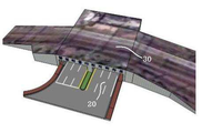
도 2a 및 도 2b는 본 발명의 박스형 지하차도를 이용한 고가도로의 개념도를 도시한 것이다.FIGS. 2A and 2B are conceptual diagrams of a flyover using a box-shaped underground roadway of the present invention.
먼저, 도 2a와 같이 박스형 지하차도(100)는 통상 지반(GL)을 기준으로 하방으로 일정한 깊이까지 굴착하고, 상기 굴착된 지반에 터널부(110)를 시공한 후, 상기 터널부(110)의 양 측방으로 접속부(120)를 시공하게 된다.First, as shown in FIG. 2A, the box-shaped
이때 터널부(110)는 예컨대 양 측벽부, 상판 및 저판 및 내부기둥(미도시)을 포함하는 구조물로 시공하게 되는데 이때 저판과 상판 사이의 단면높이(H)는 대형 차량등의 진입 등을 고려하여 지반(GL)을 기준으로 하방으로 개략 4.5~5m 이상 확보해야 한다.At this time, the
이에 터널부(110) 시공을 위한 지반의 굴착은 상기 단면높이를 고려한 굴착깊이가 될 수밖에 없고, 이에 따라 접속부(120)도 안정적인 차량 진입을 위해 구배를 충분히 확보하기 때문에 단면높이(H)가 커질수록 접속부(120) 연장길이(L)도 함께 길게 연장되어 공사비가 증가될 수밖에 없고, 부지를 확보해야 함에 따른 민원이 많이 발생할 수밖에 없게 된다.Therefore, the excavation depth of the ground for constructing the
이에 본 발명은 지반(GL)을 기준으로 하방으로 일부 단면높이(H1)를 확보하고 지반(GL)을 기준으로 상방으로도 단면높이(H2)를 확보할 수 있도록 하여 전체적(H1+H2)으로는 필요한 개략 4.5~5m 이상의 터널부 단면높이(H=H1+H2)를 충족할 수 있도록 하는 방법을 채택하게 된다.Therefore, the present invention ensures a partial sectional height H1 downward with respect to the ground GL and secures the sectional height H2 upward with respect to the ground GL, (H = H1 + H2) of the tunnel section of 4.5 to 5 m or more as necessary.
말하자면 지반(GL)을 기준으로 상방으로 상기 단면높이(H2)를 확보할 수 있도록 한 것이다. 하지만 이와 같이 시공을 하게 되면 지반(GL)을 기준으로 상방으로 터널부의 양 측벽부, 상판이 상방 돌출되도록 시공해야 한다.In other words, the cross-sectional height H2 can be secured upwards on the basis of the ground GL. However, when the construction is carried out in this way, it is necessary to construct both side walls of the tunnel part and the upper plate so as to protrude upward from the ground (GL).
이에 이러한 돌출된 터널부는 고가도로(200)로 시공하게 된다.Thus, the protruded tunnel portion is constructed by the overpass road (200).
즉, 도 2b와 같이 지하차도의 터널부는 지반(GL)의 표면까지만 시공하고 그 상부로 돌출되는 부위는 고가도로(200)의 양 교대부와 슬래브로 대체하고, 상기 바닥판은 접속도로(230)와 연결되도록 하게 된다.2B, the tunnel portion of the underground roadway is installed only up to the surface of the ground GL, and the portions protruding to the upper portion thereof are replaced by the two alternating portions and the slabs of the
이에 박스형 지하차도의 터널부(110)에 있어 단면높이(H)는 양 측벽부의 단면높이(H1)과 상기 양 교대부(210)의 단면높이(H2)로서 충분히 확보할 수 있게 된다.The sectional height H of the
이로서 박스형 지하차도의 터널부와 연결되는 접속부(120)는 터널부(110)의 단면높이(H1)를 기준으로 시공해도 되기 때문에 그 연장길이(L1)를 줄일 수 있게 되고,Therefore, the connecting
또한 고가도로(200)의 경우에도 양 교대부(210)의 하부가 터널부에 의하여 지지되도록 시공할 수 있으므로 양 교대부 하부를 지지하는 터널부(110)의 양 측벽부가 파일 역할을 할 수 있어 양 교대부 단면높이(H2)를 최소화시킬 수 있게 된다. 이로서 역시 고가도로의 높이도 줄일 수 있어 접속도로(230)의 연장길이(L3)를 줄일 수 있게 된다.Also, in the case of the
결국, 본 발명은 고가도로(200)의 양 교대부와 지하차도(100)의 양 측벽부를 서로 일체화시켜 박스형 지하차도의 단면높이를 충분히 확보할 수 있으면서도 박스형 지하차도의 접속부와 고가도로의 접속도로의 연장길이도 줄일 수 있도록 한 것임을 알 수 있다.As a result, the present invention is capable of fully securing the height of the cross-section of the box-shaped underground roadway by integrating both the alternating portions of the
[본 발명의 박스형 지하차도(100)와 고가도로(200)][Boxed
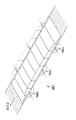
도 3a 및 도 3는 본 발명의 박스형 지하차도(100)와 고가도로(200)의 구성사시도이다.FIGS. 3A and 3 are perspective views illustrating a box-type
먼저 상기 박스형 지하차도(100)는 터널부(110)와 접속부(120)로 구분되는데 통상 터널부는 지반 굴착 후 앞서 살펴본 것과 같이 양 측벽부, 상판 및 저판및 내부기둥에 의한 철근콘크리트 구조물로 시공하게 된다.First, the box-type
하지만 이와 같은 철근콘크리트 구조물로 시공하게 되면 프리캐스트 방식으로 시공한다고 할지라도 시공성 및 공사기간을 줄이는데 한계가 있다.However, if the construction is carried out using such a reinforced concrete structure, there is a limit to reduce the workability and the construction period even if the precast method is applied.
이에 본 발명은 도 3a와 같이 터널부(110)와 접속부(120)를 U형 세그먼트 박스(100a)들로 제작하여 종방향으로 서로 연결되도록 시공하게 된다.As shown in FIG. 3A, the
이에 양 접속부(120)에서는 U형 세그먼트 박스(100a)의 양 측벽부가 터널부로 갈수록 커지도록 제작하여 종방향으로 연결되도록 하고, 터널부(110)에서는 단면높이를 H1으로 하여 제작된 것을 이용하여 종방향으로 연결시킨 것을 이용함으로서 간단하게 박스형 지하차도 시공이 가능하도록 하게 된다.In both connecting
이에 도 3b와 같이 상기 터널부(110)의 U형 세그먼트 박스(100a)의 상면에는 고가도로(200)의 양 교대부(210)가 일체로 시공되도록 하고, 상기 양 교대부 상단 사이에 슬래브(220)가 형성되도록 하여,As shown in FIG. 3B, the upper portion of the
최종 고가도로와 박스형 지하차도의 교차부에 있어 단면높이(H=H1+H2)를 확보하도록 하게 된다.(H = H1 + H2) at the intersection of the final overpass and the box-shaped underground roadway.
이에 상기 슬래브(220)와 연결되도록 접속도로(230)를 시공하게 되면 최종 고가도로의 시공도 간단하게 완성될 수 있게 됨을 알 수 있다.Thus, if the
이에 상기 고가도로의 양 교대부와 박스형 지하차도의 터널부 U형 세그먼트 박스(100a)가 상하로 일체화된 상태를 박스형 지하차도(100)라 지칭하게 된다.A state in which the two shift portions of the overpass and the tunnel portion
[본 발명의 박스형 지하차도(100)와 고가도로(200) 시공방법][Method of constructing boxed
도 4a, 도 4b 및 도 4c는 본 발명의 본 발명의 박스형 지하차도(100)와 고가도로(200) 시공방법을 순서대로 도시한 것이다.FIGS. 4A, 4B and 4C illustrate the method of constructing the box-shaped
먼저, 본 발명의 박스형 지하차도(100)는 U형 세그먼트 박스(100a)를 이용하여 터널부(110)와 접속부(120)를 시공하게 된다.First, the box-type
즉, 도 4a와 같이 접속부에 있어 단면높이가 터널부로 갈수록 커지는 형태로 U형 세그먼트 박스(100a)를 제작하여 굴착된 지반에 종방향으로 연결시켜 가면서 상기 접속부를 시공하게 된다.That is, as shown in FIG. 4A, the
이때 터널부(110)는 단면높이(H1)를 가진 U형 세그먼트 박스(100a)를 서로 연결시켜 그 상면이 지반(GL)의 표면과 일치하도록 시공하게 된다.At this time, the
다음으로는 도 4b와 같이 고가도로용 양 교대부(210)를 예컨대 현장타설 방식으로 상기 터널부의 U형 세그먼트 박스(100a) 상면에 일체로 미도시된 거푸집등을 이용하여 시공하게 된다.Next, as shown in FIG. 4B, the upper alternating
이에 설사 U형 세그먼트 박스(100a)를 프리캐스트 방식으로 시공하였다고 하더라도 양 교대부(210)의 일체화에는 별 문제가 없으며, 프리캐스트 방식으로 양 교대부를 시공하더라도 기계적 연결방식으로 인한 양 측벽부 연결은 달리 문제가 없다.Even if the
이에 상기 양 교대부(210) 시공이 완료되면 양 측벽부 상부에 슬래브(220)를 시공하게 되는데 이는 현장타설 방식을 이용하여 시공할 수 있을 것이며 슬래브(220)가 시공되면 접속도로(230)를 시공하여 고가도로(200)의 시공도 완성될 수 있도록 하게 된다.When the
다음으로는 도 4c와 같이 박스형 지하차도에 있어 접속부와 터널부 내부를 포장하고, 역시 양 교대부 주위는 보강토옹벽을 처리하는 방식으로 최종 본 발명의 박스형 지하차도(100)와 고가도로(200) 시공을 완성할 수 있도록 하게 된다.Next, as shown in FIG. 4C, the connection portion and the tunnel portion are packed in a box-shaped underground roadway, and the reinforced earth retaining walls are also wrapped around both of the alternate portions to construct the box-shaped
전술한 본 발명의 설명은 예시를 위한 것이며, 본 발명이 속하는 기술분야의 통상의 지식을 가진 자는 본 발명의 기술적 사상이나 필수적인 특징을 변경하지 않고서 다른 구체적인 형태로 쉽게 변형이 가능하다는 것을 이해할 수 있을 것이다. 그러므로 이상에서 기술한 실시예들은 모든 면에서 예시적인 것이며 한정적이 아닌 것으로 이해해야만 한다. 예를 들어, 단일형으로 설명되어 있는 각 구성 요소는 분산되어 실시될 수도 있으며, 마찬가지로 분산된 것으로 설명되어 있는 구성 요소들도 결합된 형태로 실시될 수 있다.It will be understood by those skilled in the art that the foregoing description of the present invention is for illustrative purposes only and that those of ordinary skill in the art can readily understand that various changes and modifications may be made without departing from the spirit or essential characteristics of the present invention. will be. It is therefore to be understood that the above-described embodiments are illustrative in all aspects and not restrictive. For example, each component described as a single entity may be distributed and implemented, and components described as being distributed may also be implemented in a combined form.
본 발명의 범위는 상기 상세한 설명보다는 후술하는 특허청구범위에 의하여 나타내어지며, 특허청구범위의 의미 및 범위 그리고 그 균등 개념으로부터 도출되는 모든 변경 또는 변형된 형태가 본 발명의 범위에 포함되는 것으로 해석되어야 한다.The scope of the present invention is defined by the appended claims rather than the detailed description and all changes or modifications derived from the meaning and scope of the claims and their equivalents are to be construed as being included within the scope of the present invention do.
100: 박스형 지하차도
100a: U형 세그먼트 박스
110: 터널부
120: 접속부
200: 고가도로
210: 양 교대부
220: 슬래브
230: 접속도로100: boxed underground car
100a: U-shaped segment box
110: tunnel part
120:
200: Overpass
210:
220: Slab
230: Access road
Claims (4)
상기 터널부(110)와 접속부(120)는 지반(GL) 아래로 U형 세그먼트 박스(100a)를 이용하여 종방향으로 서로 연결시켜 가면서 시공하도록 하는 단계; 및
상기 터널부(110)에 시공된 U형 세그먼트 박스(100a)의 양 측벽부 상면에 지반(GL) 위쪽으로 고가도로의 양 교대부(210)가 일체로 시공되도록 하고, 양 교대부 사이에 슬래브(220)를 시공한 후 상기 슬래브에 접속도로(230)를 시공하는 단계;를 포함하여,
상기 U형 세그먼트 박스(100a)가 고가도로의 양 교대부(210)를 지지하도록 하여 지하차도 상부에 고가도로가 시공되도록 하는 것을 특징으로 하는 박스형 지하차도를 이용한 고가도로 시공방법.A method of constructing an overpass road construction in which an elevated road including both alternating sections, slabs, and connection roads is installed across an underground roadway including a tunnel section and a connection section below the ground section GL,
The tunnel part 110 and the connection part 120 are connected to each other in the longitudinal direction by using the U-shaped segment box 100a under the ground GL; And
The upper alternating portion 210 of the elevated road is integrally installed above the ground GL on the upper surface of both side walls of the U-shaped segment box 100a installed in the tunnel portion 110, 220), and then installing the connection road (230) on the slab,
Wherein the U-shaped segment box (100a) supports both alternating portions (210) of the overpass, so that a highway is constructed on the underpass.
상기 U형 세그먼트 박스(100a)는
양 측벽부; 및 양 측벽부 하단을 서로 연결하는 저판(120)을 포함하여 형성된 것으로서 종방향으로 연결되어 지하차도가 시공되도록 하는 것을 특징으로 하는 박스형 지하차도를 이용한 고가도로 시공방법.The method according to claim 1,
The U-shaped segment box 100a
Both side wall portions; And a bottom plate (120) connecting the lower ends of both side wall portions to each other so as to be connected to each other in the longitudinal direction so as to construct an underground roadway.
상기 고가도로(200)는
상기 U형 세그먼트 박스(100a)의 양 측벽부와 양 교대부(210)가 상하로 서로 일체화되도록 하고, 상기 양 교대부 상단 사이에 슬래브(220)가 일체로 형성됨으로서 지하차도와 고가도로의 교차부에서 서로 박스형으로 형성되도록 하는 것을 특징으로 하는 박스형 지하차도를 이용한 고가도로 시공방법.3. The method of claim 2,
The flyover (200)
The two sidewall portions and the two alternating portions 210 of the U-shaped segment box 100a are vertically integrated with each other, and the slabs 220 are integrally formed between the upper ends of the two alternating portions, Wherein the at least one box-shaped underground roadway is formed in a box shape.
상기 U형 세그먼트 박스(100a)는 프리캐스트 상기 U형 세그먼트 박스(100a)로 제작된 것을 이용하고,
상기 양 교대부와 슬래브는 현장타설 콘크리트로 상기 U형 세그먼트 박스(100a)와 일체로 형성되도록 하는 것을 특징으로 하는 박스형 지하차도를 이용한 고가도로 시공방법.The method of claim 3,
The U-shaped segment box 100a is made of precast U-shaped segment box 100a,
Wherein the two alternating portions and the slabs are formed as spot-filled concrete and are integrally formed with the U-shaped segment box (100a).
Priority Applications (1)
| Application Number | Priority Date | Filing Date | Title |
|---|---|---|---|
| KR1020130111144A KR101591303B1 (en) | 2013-09-16 | 2013-09-16 | Overpass bridge construction method using box type underpass structure |
Applications Claiming Priority (1)
| Application Number | Priority Date | Filing Date | Title |
|---|---|---|---|
| KR1020130111144A KR101591303B1 (en) | 2013-09-16 | 2013-09-16 | Overpass bridge construction method using box type underpass structure |
Publications (2)
| Publication Number | Publication Date |
|---|---|
| KR20150031670A true KR20150031670A (en) | 2015-03-25 |
| KR101591303B1 KR101591303B1 (en) | 2016-02-04 |
Family
ID=53025132
Family Applications (1)
| Application Number | Title | Priority Date | Filing Date |
|---|---|---|---|
| KR1020130111144A KR101591303B1 (en) | 2013-09-16 | 2013-09-16 | Overpass bridge construction method using box type underpass structure |
Country Status (1)
| Country | Link |
|---|---|
| KR (1) | KR101591303B1 (en) |
Cited By (4)
| Publication number | Priority date | Publication date | Assignee | Title |
|---|---|---|---|---|
| CN106436515A (en) * | 2016-08-31 | 2017-02-22 | 中铁第四勘察设计院集团有限公司 | Road intersection structure |
| KR20200039869A (en) * | 2018-10-05 | 2020-04-17 | 주식회사 경호엔지니어링 종합건축사사무소 | Underpass passing through the soft soil using cable-stayed type amd construction method of the same |
| CN111809501A (en) * | 2020-08-18 | 2020-10-23 | 中交第一公路勘察设计研究院有限公司 | Arched bent suspension bridge structure |
| KR20210035788A (en) * | 2018-10-05 | 2021-04-01 | 주식회사 경호엔지니어링 종합건축사사무소 | Construction method of underpass using cable-stayed type |
Family Cites Families (1)
| Publication number | Priority date | Publication date | Assignee | Title |
|---|---|---|---|---|
| JP4917576B2 (en) * | 2008-06-27 | 2012-04-18 | 隆昭 遠藤 | Precast concrete foundation slab and its construction method |
-
2013
- 2013-09-16 KR KR1020130111144A patent/KR101591303B1/en active IP Right Grant
Cited By (4)
| Publication number | Priority date | Publication date | Assignee | Title |
|---|---|---|---|---|
| CN106436515A (en) * | 2016-08-31 | 2017-02-22 | 中铁第四勘察设计院集团有限公司 | Road intersection structure |
| KR20200039869A (en) * | 2018-10-05 | 2020-04-17 | 주식회사 경호엔지니어링 종합건축사사무소 | Underpass passing through the soft soil using cable-stayed type amd construction method of the same |
| KR20210035788A (en) * | 2018-10-05 | 2021-04-01 | 주식회사 경호엔지니어링 종합건축사사무소 | Construction method of underpass using cable-stayed type |
| CN111809501A (en) * | 2020-08-18 | 2020-10-23 | 中交第一公路勘察设计研究院有限公司 | Arched bent suspension bridge structure |
Also Published As
| Publication number | Publication date |
|---|---|
| KR101591303B1 (en) | 2016-02-04 |
Similar Documents
| Publication | Publication Date | Title |
|---|---|---|
| KR101344063B1 (en) | The construction method of steel-concrete underpass | |
| KR101591303B1 (en) | Overpass bridge construction method using box type underpass structure | |
| KR20100138122A (en) | Base of arch rigid frame structure including composite covering arch structure and constructing method thereof | |
| JP7061002B2 (en) | How to repair a bridge | |
| KR100971200B1 (en) | Precast box structure construction method using steel connection member | |
| KR101206860B1 (en) | Excavation tunnel constructing method using vertical side wall and arch ceiling | |
| JP4406577B2 (en) | Digging road | |
| KR101440028B1 (en) | Underground tunnel structure crossing rail way, and Constructing Method thereof | |
| JP2017096063A (en) | Earth retaining excavation method and skeleton construction method | |
| KR102254243B1 (en) | Non-utility facilities and non-open cut underground structure and their construction methods | |
| JP3938777B2 (en) | Construction method of crossing underground structure and crossing underground structure | |
| KR101427812B1 (en) | Open cut method for constructing an underground structure | |
| JP6173087B2 (en) | Method for reinforcing concrete structures | |
| JP5915074B2 (en) | How to form an underground space under a ground transportation | |
| JP2007126936A (en) | Semisubterranean road and its construction method | |
| KR101234091B1 (en) | Method of underground railway crossing over direct installation of precast concrete slab | |
| KR102292152B1 (en) | Top-down construction method with underground utility | |
| KR101439400B1 (en) | A hinged base structure of arch-shaped composite structure with the precast concrete pannel and the steel frame using the open trench tunnel and method for constructing arch-shaped open trench tunnel | |
| JP5192422B2 (en) | Support pile construction method for construction of crossing structure under track | |
| JP2004332357A (en) | Method for constructing elevated type traffic route and elevated type traffic route | |
| KR100959946B1 (en) | Constructing method of loop structure by tension force and loop structure constructed by this | |
| JP2006249734A (en) | Construction method of crossing underground structure and crossing underground structure | |
| JP6823389B2 (en) | Railroad support structure | |
| JP2004257184A (en) | Structure of grade separated crossing of road, and its construction method | |
| JP2004084367A (en) | Foundation structure and elevated traffic way |
Legal Events
| Date | Code | Title | Description |
|---|---|---|---|
| A201 | Request for examination | ||
| E902 | Notification of reason for refusal | ||
| E90F | Notification of reason for final refusal | ||
| E701 | Decision to grant or registration of patent right | ||
| FPAY | Annual fee payment |
Payment date: 20181211 Year of fee payment: 4 |
|
| FPAY | Annual fee payment |
Payment date: 20191210 Year of fee payment: 5 |