KR20150021267A - Rotary type dust removing machine - Google Patents
Rotary type dust removing machine Download PDFInfo
- Publication number
- KR20150021267A KR20150021267A KR20130098403A KR20130098403A KR20150021267A KR 20150021267 A KR20150021267 A KR 20150021267A KR 20130098403 A KR20130098403 A KR 20130098403A KR 20130098403 A KR20130098403 A KR 20130098403A KR 20150021267 A KR20150021267 A KR 20150021267A
- Authority
- KR
- South Korea
- Prior art keywords
- rake
- screen
- water
- water channel
- contaminants
- Prior art date
Links
Images


Classifications
-
- E—FIXED CONSTRUCTIONS
- E02—HYDRAULIC ENGINEERING; FOUNDATIONS; SOIL SHIFTING
- E02B—HYDRAULIC ENGINEERING
- E02B5/00—Artificial water canals, e.g. irrigation canals
- E02B5/08—Details, e.g. gates, screens
Abstract
The present invention has a cleaning means for forcibly removing a contaminant which is adhered to a rake so as not to cause a breakdown of the apparatus due to a breakage between the screen and the screen during the movement of the obstacle raised in the screen apparatus installed in the water channel And to provide a rotary damper device. To this end, the present invention provides a water treatment system comprising: a screen installed in a frame structure to form a water channel for flowing water between both side walls and to filter contaminants contained in water flowing in the water channel; A rotary damper comprising a chain mechanism that travels in a track and a main body including a rake which moves by driving the chain mechanism and lifts up the impurities caught on the screen below the water channel to the upper side and discharges it to the outside, And a cleaning member provided with a brush member for dropping the contaminants to the backside of the washing tank and detaching the contaminants remaining in the washing tank by friction contact with the rake.
Description
The present invention relates to a water treatment system that is installed in an open channel of a low-lying drainage pumping station, a water supply water intake pipe, a related water supply channel, a sewage treatment plant and a dam, And more particularly to a rotary damper device having a cleaning means capable of removing contaminants circulating between rakes without being discharged to the outside.
Recently, water intake and drainage capacities have been increasing due to the enlargement of various water intake and drainage pumping stations, and sewage and stormwater pumping stations have been installed in many places depending on the progress of sewerage supply. In these water treatment plants, If there is contamination of dirt and garbage, so-called various impurities, the pump will be broken or the pumping function will be considerably weakened, and these trash will block the water channel, It involves several problems.
For this reason, the flow of the water flow is made smooth by arranging the dust collector on the water line so that the impurities which flow into the drainage channel together with the water flow can not flow to the pump side.
As shown in Fig. 1, there is a "front elevating type rotary damper" disclosed in Korean Utility Model Registration No. 325084, which is installed in the middle of a drainage passage to automatically filter out contaminants and discharge the damages to the outside. The operation relationship is as follows.
The rotary damper according to the present invention includes a
When the
The reason why the
However, all conventional arrangements, including the above-mentioned damper device, have shown that when the
SUMMARY OF THE INVENTION The present invention has been made in view of the above-mentioned problems, and it is an object of the present invention to provide a screening apparatus for a watercourse, which is capable of preventing a breakage of the apparatus, And a cleaning means for forcibly removing contaminants which are stuck together.
In order to attain the above object, the vibration damper of the present invention comprises a screen provided on a frame structure so as to form a water channel through which water flows between both side walls, to filter contaminants contained in the water flowing in the water channel, A chain mechanism that is installed on the frame structure to travel in an endless track and a body that includes a main body including a rake which is moved by driving the chain mechanism and lifts up the impurities caught on the screen of the lower portion of the water channel to the upper side and discharges it to the outside, A cleaning means having a brush member for dropping the contaminants to the rear surface of the main body provided with the screen and detaching the contaminants remaining in the rake by friction contact with the rake is provided.
According to the present invention, the bristle member is formed of an elastic plastic wire material or an elastic metal wire material.
According to the present invention, the rake which is circulatingly driven by the chain lifts up the contaminants caught on the screen at the lower part of the water channel, and when the conveying direction of the upper sprocket wheel of the apparatus is changed from the lowering state to the lowering state, To the outside of the conveyance Ken-Bayer system, and when the rake is moved downward, the bristles of the bristle cleaning means, passing through the rake, And the scum, such as a member or vinyl, is removed, whereby the scum is caught between the rake and the screen, thereby inducing an overload of the motor and preventing damage to the motor and the apparatus.
1 is a view for explaining a conventional technique.
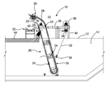
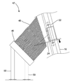
2 is a side view showing a state in which a rotary damper according to the present invention is installed in a water channel so as to filter out contaminants,
3 is a perspective view showing a cleaning means of the rotary damper according to the present invention,
FIG. 4 is an enlarged view of a part of a rotary silencer according to the present invention showing a state in which the cleaning means cleans the contaminants from the rake. FIG.
DESCRIPTION OF THE PREFERRED EMBODIMENTS Hereinafter, preferred embodiments of the present invention will be described with reference to the accompanying drawings in order to fully understand the present invention. The embodiments of the present invention may be modified into various forms, and the scope of the present invention should not be construed as being limited to the embodiments described in detail below. The present embodiments are provided to enable those skilled in the art to more fully understand the present invention. Therefore, the shapes and the like of the elements in the drawings can be exaggeratedly expressed to emphasize a clearer description. It should be noted that in the drawings, the same members are denoted by the same reference numerals. Further, detailed descriptions of known functions and configurations that may unnecessarily obscure the gist of the present invention will be omitted, and, if necessary, reference will be made to drawings in the prior art.
Hereinafter, a rotary damper of the present invention will be described in detail with reference to the preferred embodiments of the present invention with reference to the accompanying drawings.
In Fig. 2, the rotary damper device of the present invention is indicated generally by the
The
One of the apparatuses of the
A cleaning means 42 for cleaning the
4, the
In order to filter the contaminants that have fallen into the water drained through the
However, when the
Preferred embodiments of the invention are described herein, which is the best mode known to the inventors for carrying out the invention. It will be readily apparent to those skilled in the art that modifications of these preferred embodiments are possible from the foregoing description. The inventors expect that skilled artisans will employ these variations, and the inventors intend to practice the invention in addition to those specifically described above. Accordingly, the invention includes all modifications that are equivalent to the subject matter recited in the claims appended hereto as permitted by applicable law. Further, all possible combinations of the above-mentioned elements will be included in the present invention unless specifically mentioned or excluded in the present specification.
10: Rotary damper device 12: Side wall of the channel
12a: upper surface of the side wall 14:
16: frame structure 18: screen device
20: chain mechanism 22: chain
24: Lake 26:
28: center of rotation shaft 30: rope fastener
32: wire rope 34: drum
36: motor 38: work table
40: support leg 42: cleaning means
44: slab bottom surface 46: base plate
48: bristle member 50: support leg member
52: Transferring conveyer device
Claims (2)
Priority Applications (1)
| Application Number | Priority Date | Filing Date | Title |
|---|---|---|---|
| KR20130098403A KR20150021267A (en) | 2013-08-20 | 2013-08-20 | Rotary type dust removing machine |
Applications Claiming Priority (1)
| Application Number | Priority Date | Filing Date | Title |
|---|---|---|---|
| KR20130098403A KR20150021267A (en) | 2013-08-20 | 2013-08-20 | Rotary type dust removing machine |
Publications (1)
| Publication Number | Publication Date |
|---|---|
| KR20150021267A true KR20150021267A (en) | 2015-03-02 |
Family
ID=53019713
Family Applications (1)
| Application Number | Title | Priority Date | Filing Date |
|---|---|---|---|
| KR20130098403A KR20150021267A (en) | 2013-08-20 | 2013-08-20 | Rotary type dust removing machine |
Country Status (1)
| Country | Link |
|---|---|
| KR (1) | KR20150021267A (en) |
Cited By (2)
| Publication number | Priority date | Publication date | Assignee | Title |
|---|---|---|---|---|
| CN108035315A (en) * | 2017-12-21 | 2018-05-15 | 河南禹王水工机械有限公司 | Novel rotary type trash |
| CN111773812A (en) * | 2020-07-11 | 2020-10-16 | 李看 | Low-resistance energy-saving slag scraper for sewage filtration |
-
2013
- 2013-08-20 KR KR20130098403A patent/KR20150021267A/en not_active Application Discontinuation
Cited By (2)
| Publication number | Priority date | Publication date | Assignee | Title |
|---|---|---|---|---|
| CN108035315A (en) * | 2017-12-21 | 2018-05-15 | 河南禹王水工机械有限公司 | Novel rotary type trash |
| CN111773812A (en) * | 2020-07-11 | 2020-10-16 | 李看 | Low-resistance energy-saving slag scraper for sewage filtration |
Similar Documents
| Publication | Publication Date | Title |
|---|---|---|
| KR100987812B1 (en) | dust removing machine for sewage and draining disposal | |
| KR101084319B1 (en) | Remaining rubbish removal apparatus of floating waste removal machine | |
| KR101099431B1 (en) | Rotary type trash remover | |
| KR100540219B1 (en) | Adultration removing method of a link type dash pot and link type dash pot thereof | |
| KR100956129B1 (en) | Rotary type dust removing machine | |
| KR101599504B1 (en) | Rotary type dust removing machine | |
| KR100911346B1 (en) | Movable dust remover | |
| KR101331968B1 (en) | A rotary screen which is possessed of a cutting apparatus | |
| KR101110668B1 (en) | Rotary screen | |
| KR100649667B1 (en) | Apparatus for collecting sewage in a drainage with rake type cleaner | |
| KR20150021267A (en) | Rotary type dust removing machine | |
| KR101594101B1 (en) | In/out dust remover | |
| KR101234049B1 (en) | Rotary dust remover for gate pump | |
| KR101738353B1 (en) | Rotary type scraper | |
| KR20190119750A (en) | A rotary trash remover type of divided waterway | |
| KR100623221B1 (en) | a scrape together system for floating waste | |
| KR20100135470A (en) | Dust removing machine | |
| KR101599999B1 (en) | Rotary type dust removing machine | |
| KR101403773B1 (en) | Automatic dust removing machine having means for prevention of the residual sludge inflowing to a hiatus | |
| KR20020092765A (en) | rotary type dust removing machine | |
| KR101887831B1 (en) | Stepwise filter equipped with structure of preventing contaminant sedimentation | |
| KR101254694B1 (en) | Dust removing machine | |
| KR101365038B1 (en) | A rotary type debris removal apparatus | |
| KR100424430B1 (en) | A single body type trash remover self weight | |
| KR20200020041A (en) | A Rotary Type Dust Removing Machine Equipped with Rotating Front Screen Working with Rake and Adulteration Removal Device |
Legal Events
| Date | Code | Title | Description |
|---|---|---|---|
| A201 | Request for examination | ||
| E902 | Notification of reason for refusal | ||
| E601 | Decision to refuse application |