KR20150014466A - Durable adsorbent material and adsorbent packs - Google Patents
Durable adsorbent material and adsorbent packs Download PDFInfo
- Publication number
- KR20150014466A KR20150014466A KR1020147032989A KR20147032989A KR20150014466A KR 20150014466 A KR20150014466 A KR 20150014466A KR 1020147032989 A KR1020147032989 A KR 1020147032989A KR 20147032989 A KR20147032989 A KR 20147032989A KR 20150014466 A KR20150014466 A KR 20150014466A
- Authority
- KR
- South Korea
- Prior art keywords
- sheet
- adsorbent
- adsorption
- parallel
- binder
- Prior art date
Links
Images


Classifications
-
- B—PERFORMING OPERATIONS; TRANSPORTING
- B01—PHYSICAL OR CHEMICAL PROCESSES OR APPARATUS IN GENERAL
- B01D—SEPARATION
- B01D53/00—Separation of gases or vapours; Recovering vapours of volatile solvents from gases; Chemical or biological purification of waste gases, e.g. engine exhaust gases, smoke, fumes, flue gases, aerosols
- B01D53/02—Separation of gases or vapours; Recovering vapours of volatile solvents from gases; Chemical or biological purification of waste gases, e.g. engine exhaust gases, smoke, fumes, flue gases, aerosols by adsorption, e.g. preparative gas chromatography
- B01D53/04—Separation of gases or vapours; Recovering vapours of volatile solvents from gases; Chemical or biological purification of waste gases, e.g. engine exhaust gases, smoke, fumes, flue gases, aerosols by adsorption, e.g. preparative gas chromatography with stationary adsorbents
- B01D53/047—Pressure swing adsorption
-
- B—PERFORMING OPERATIONS; TRANSPORTING
- B01—PHYSICAL OR CHEMICAL PROCESSES OR APPARATUS IN GENERAL
- B01D—SEPARATION
- B01D39/00—Filtering material for liquid or gaseous fluids
-
- B—PERFORMING OPERATIONS; TRANSPORTING
- B01—PHYSICAL OR CHEMICAL PROCESSES OR APPARATUS IN GENERAL
- B01D—SEPARATION
- B01D46/00—Filters or filtering processes specially modified for separating dispersed particles from gases or vapours
-
- B—PERFORMING OPERATIONS; TRANSPORTING
- B01—PHYSICAL OR CHEMICAL PROCESSES OR APPARATUS IN GENERAL
- B01D—SEPARATION
- B01D53/00—Separation of gases or vapours; Recovering vapours of volatile solvents from gases; Chemical or biological purification of waste gases, e.g. engine exhaust gases, smoke, fumes, flue gases, aerosols
- B01D53/02—Separation of gases or vapours; Recovering vapours of volatile solvents from gases; Chemical or biological purification of waste gases, e.g. engine exhaust gases, smoke, fumes, flue gases, aerosols by adsorption, e.g. preparative gas chromatography
- B01D53/04—Separation of gases or vapours; Recovering vapours of volatile solvents from gases; Chemical or biological purification of waste gases, e.g. engine exhaust gases, smoke, fumes, flue gases, aerosols by adsorption, e.g. preparative gas chromatography with stationary adsorbents
- B01D53/0407—Constructional details of adsorbing systems
- B01D53/0423—Beds in columns
-
- B—PERFORMING OPERATIONS; TRANSPORTING
- B01—PHYSICAL OR CHEMICAL PROCESSES OR APPARATUS IN GENERAL
- B01J—CHEMICAL OR PHYSICAL PROCESSES, e.g. CATALYSIS OR COLLOID CHEMISTRY; THEIR RELEVANT APPARATUS
- B01J20/00—Solid sorbent compositions or filter aid compositions; Sorbents for chromatography; Processes for preparing, regenerating or reactivating thereof
- B01J20/02—Solid sorbent compositions or filter aid compositions; Sorbents for chromatography; Processes for preparing, regenerating or reactivating thereof comprising inorganic material
- B01J20/06—Solid sorbent compositions or filter aid compositions; Sorbents for chromatography; Processes for preparing, regenerating or reactivating thereof comprising inorganic material comprising oxides or hydroxides of metals not provided for in group B01J20/04
- B01J20/08—Solid sorbent compositions or filter aid compositions; Sorbents for chromatography; Processes for preparing, regenerating or reactivating thereof comprising inorganic material comprising oxides or hydroxides of metals not provided for in group B01J20/04 comprising aluminium oxide or hydroxide; comprising bauxite
-
- B—PERFORMING OPERATIONS; TRANSPORTING
- B01—PHYSICAL OR CHEMICAL PROCESSES OR APPARATUS IN GENERAL
- B01J—CHEMICAL OR PHYSICAL PROCESSES, e.g. CATALYSIS OR COLLOID CHEMISTRY; THEIR RELEVANT APPARATUS
- B01J20/00—Solid sorbent compositions or filter aid compositions; Sorbents for chromatography; Processes for preparing, regenerating or reactivating thereof
- B01J20/02—Solid sorbent compositions or filter aid compositions; Sorbents for chromatography; Processes for preparing, regenerating or reactivating thereof comprising inorganic material
- B01J20/10—Solid sorbent compositions or filter aid compositions; Sorbents for chromatography; Processes for preparing, regenerating or reactivating thereof comprising inorganic material comprising silica or silicate
- B01J20/16—Alumino-silicates
- B01J20/18—Synthetic zeolitic molecular sieves
-
- B—PERFORMING OPERATIONS; TRANSPORTING
- B01—PHYSICAL OR CHEMICAL PROCESSES OR APPARATUS IN GENERAL
- B01J—CHEMICAL OR PHYSICAL PROCESSES, e.g. CATALYSIS OR COLLOID CHEMISTRY; THEIR RELEVANT APPARATUS
- B01J20/00—Solid sorbent compositions or filter aid compositions; Sorbents for chromatography; Processes for preparing, regenerating or reactivating thereof
- B01J20/02—Solid sorbent compositions or filter aid compositions; Sorbents for chromatography; Processes for preparing, regenerating or reactivating thereof comprising inorganic material
- B01J20/20—Solid sorbent compositions or filter aid compositions; Sorbents for chromatography; Processes for preparing, regenerating or reactivating thereof comprising inorganic material comprising free carbon; comprising carbon obtained by carbonising processes
-
- B—PERFORMING OPERATIONS; TRANSPORTING
- B01—PHYSICAL OR CHEMICAL PROCESSES OR APPARATUS IN GENERAL
- B01J—CHEMICAL OR PHYSICAL PROCESSES, e.g. CATALYSIS OR COLLOID CHEMISTRY; THEIR RELEVANT APPARATUS
- B01J20/00—Solid sorbent compositions or filter aid compositions; Sorbents for chromatography; Processes for preparing, regenerating or reactivating thereof
- B01J20/28—Solid sorbent compositions or filter aid compositions; Sorbents for chromatography; Processes for preparing, regenerating or reactivating thereof characterised by their form or physical properties
- B01J20/28014—Solid sorbent compositions or filter aid compositions; Sorbents for chromatography; Processes for preparing, regenerating or reactivating thereof characterised by their form or physical properties characterised by their form
- B01J20/28026—Particles within, immobilised, dispersed, entrapped in or on a matrix, e.g. a resin
-
- B—PERFORMING OPERATIONS; TRANSPORTING
- B01—PHYSICAL OR CHEMICAL PROCESSES OR APPARATUS IN GENERAL
- B01J—CHEMICAL OR PHYSICAL PROCESSES, e.g. CATALYSIS OR COLLOID CHEMISTRY; THEIR RELEVANT APPARATUS
- B01J20/00—Solid sorbent compositions or filter aid compositions; Sorbents for chromatography; Processes for preparing, regenerating or reactivating thereof
- B01J20/28—Solid sorbent compositions or filter aid compositions; Sorbents for chromatography; Processes for preparing, regenerating or reactivating thereof characterised by their form or physical properties
- B01J20/28014—Solid sorbent compositions or filter aid compositions; Sorbents for chromatography; Processes for preparing, regenerating or reactivating thereof characterised by their form or physical properties characterised by their form
- B01J20/2803—Sorbents comprising a binder, e.g. for forming aggregated, agglomerated or granulated products
-
- B—PERFORMING OPERATIONS; TRANSPORTING
- B01—PHYSICAL OR CHEMICAL PROCESSES OR APPARATUS IN GENERAL
- B01J—CHEMICAL OR PHYSICAL PROCESSES, e.g. CATALYSIS OR COLLOID CHEMISTRY; THEIR RELEVANT APPARATUS
- B01J20/00—Solid sorbent compositions or filter aid compositions; Sorbents for chromatography; Processes for preparing, regenerating or reactivating thereof
- B01J20/28—Solid sorbent compositions or filter aid compositions; Sorbents for chromatography; Processes for preparing, regenerating or reactivating thereof characterised by their form or physical properties
- B01J20/28014—Solid sorbent compositions or filter aid compositions; Sorbents for chromatography; Processes for preparing, regenerating or reactivating thereof characterised by their form or physical properties characterised by their form
- B01J20/28033—Membrane, sheet, cloth, pad, lamellar or mat
- B01J20/2804—Sheets with a specific shape, e.g. corrugated, folded, pleated, helical
-
- B—PERFORMING OPERATIONS; TRANSPORTING
- B01—PHYSICAL OR CHEMICAL PROCESSES OR APPARATUS IN GENERAL
- B01J—CHEMICAL OR PHYSICAL PROCESSES, e.g. CATALYSIS OR COLLOID CHEMISTRY; THEIR RELEVANT APPARATUS
- B01J20/00—Solid sorbent compositions or filter aid compositions; Sorbents for chromatography; Processes for preparing, regenerating or reactivating thereof
- B01J20/28—Solid sorbent compositions or filter aid compositions; Sorbents for chromatography; Processes for preparing, regenerating or reactivating thereof characterised by their form or physical properties
- B01J20/28014—Solid sorbent compositions or filter aid compositions; Sorbents for chromatography; Processes for preparing, regenerating or reactivating thereof characterised by their form or physical properties characterised by their form
- B01J20/28042—Shaped bodies; Monolithic structures
-
- C—CHEMISTRY; METALLURGY
- C08—ORGANIC MACROMOLECULAR COMPOUNDS; THEIR PREPARATION OR CHEMICAL WORKING-UP; COMPOSITIONS BASED THEREON
- C08L—COMPOSITIONS OF MACROMOLECULAR COMPOUNDS
- C08L23/00—Compositions of homopolymers or copolymers of unsaturated aliphatic hydrocarbons having only one carbon-to-carbon double bond; Compositions of derivatives of such polymers
- C08L23/02—Compositions of homopolymers or copolymers of unsaturated aliphatic hydrocarbons having only one carbon-to-carbon double bond; Compositions of derivatives of such polymers not modified by chemical after-treatment
- C08L23/04—Homopolymers or copolymers of ethene
- C08L23/06—Polyethene
-
- B—PERFORMING OPERATIONS; TRANSPORTING
- B01—PHYSICAL OR CHEMICAL PROCESSES OR APPARATUS IN GENERAL
- B01D—SEPARATION
- B01D2253/00—Adsorbents used in seperation treatment of gases and vapours
- B01D2253/30—Physical properties of adsorbents
- B01D2253/34—Specific shapes
-
- B—PERFORMING OPERATIONS; TRANSPORTING
- B01—PHYSICAL OR CHEMICAL PROCESSES OR APPARATUS IN GENERAL
- B01D—SEPARATION
- B01D53/00—Separation of gases or vapours; Recovering vapours of volatile solvents from gases; Chemical or biological purification of waste gases, e.g. engine exhaust gases, smoke, fumes, flue gases, aerosols
- B01D53/02—Separation of gases or vapours; Recovering vapours of volatile solvents from gases; Chemical or biological purification of waste gases, e.g. engine exhaust gases, smoke, fumes, flue gases, aerosols by adsorption, e.g. preparative gas chromatography
- B01D53/04—Separation of gases or vapours; Recovering vapours of volatile solvents from gases; Chemical or biological purification of waste gases, e.g. engine exhaust gases, smoke, fumes, flue gases, aerosols by adsorption, e.g. preparative gas chromatography with stationary adsorbents
- B01D53/0462—Temperature swing adsorption
-
- B—PERFORMING OPERATIONS; TRANSPORTING
- B01—PHYSICAL OR CHEMICAL PROCESSES OR APPARATUS IN GENERAL
- B01D—SEPARATION
- B01D53/00—Separation of gases or vapours; Recovering vapours of volatile solvents from gases; Chemical or biological purification of waste gases, e.g. engine exhaust gases, smoke, fumes, flue gases, aerosols
- B01D53/02—Separation of gases or vapours; Recovering vapours of volatile solvents from gases; Chemical or biological purification of waste gases, e.g. engine exhaust gases, smoke, fumes, flue gases, aerosols by adsorption, e.g. preparative gas chromatography
- B01D53/04—Separation of gases or vapours; Recovering vapours of volatile solvents from gases; Chemical or biological purification of waste gases, e.g. engine exhaust gases, smoke, fumes, flue gases, aerosols by adsorption, e.g. preparative gas chromatography with stationary adsorbents
- B01D53/047—Pressure swing adsorption
- B01D53/0476—Vacuum pressure swing adsorption
-
- Y—GENERAL TAGGING OF NEW TECHNOLOGICAL DEVELOPMENTS; GENERAL TAGGING OF CROSS-SECTIONAL TECHNOLOGIES SPANNING OVER SEVERAL SECTIONS OF THE IPC; TECHNICAL SUBJECTS COVERED BY FORMER USPC CROSS-REFERENCE ART COLLECTIONS [XRACs] AND DIGESTS
- Y02—TECHNOLOGIES OR APPLICATIONS FOR MITIGATION OR ADAPTATION AGAINST CLIMATE CHANGE
- Y02C—CAPTURE, STORAGE, SEQUESTRATION OR DISPOSAL OF GREENHOUSE GASES [GHG]
- Y02C20/00—Capture or disposal of greenhouse gases
- Y02C20/40—Capture or disposal of greenhouse gases of CO2
Abstract
본원에서는 기류를 허용하도록 기계적으로 배치된 다중 중첩 층으로 배열된 하나 이상의 자가 지지 흡착 시트를 갖는, 압력 전환 흡착(PSA), 압력 및 온도 전환 흡착(PTSA), 또는 진공 압력 전환 흡착(VPSA) 시스템에서 유용할 수 있는 평행 통과 압축기가 제공된다. 또한, 이러한 평행 통과 접촉기를 이용하는 시스템 및 접촉기의 제조 방법이 제공된다.(PSA), Pressure and Temperature Conversion Adsorption (PTSA), or Vacuum Pressure Conversion Adsorption (VPSA) systems with one or more self supporting adsorbent sheets arranged in multiple overlapping layers mechanically arranged to allow air flow. Lt; RTI ID = 0.0 > parallel < / RTI > In addition, a system using such a parallel passage contactor and a method of manufacturing a contactor are provided.
Description
본 출원은 본원에서 그 전문이 참조로 도입된 2012. 4. 24. 출원된 U.S. 가출원 61/637,517을 우선권으로 하는 이익을 청구한다.This application is a continuation-in-part of U. S. Patent Application Serial No. 60 / Claim 61 / 637,517 as a priority.
발명의 분야Field of invention
본 발명은 흡착재, 흡착 팩, 흡착재 및/또는 흡착 팩의 제조 방법, 및 기체의 농축 및/또는 감소 방법에 관한 것이다.The present invention relates to a sorbent material, a sorbent pack, a sorbent material and / or a method for producing an adsorption pack, and a method for concentrating and / or reducing gasses.
흡착 입자 및 결합제를 포함하는 자가 지지 흡착재는 다양한 용도에서 사용된다. 그러나 일부 용도, 예컨대 압력 전환 흡착은 매우 까다로우며 현재 이용가능한 흡착재는 높은 결합제 함량 없이는 충분한 강도 및 내구성이 부족하다. 압력 전환 흡착 흡착제는 전형적으로 여러 단점을 갖는 상이한 형태의 흡착 과립이 패킹된 층이다. 이들 흡착재는 압력 전환 사이클의 손상 효과로 물리적으로 분해된다. 또한, 과립층을 통한 높은 압력 강하로 인해 패킹된 층으로부터의 과립 상승을 최소화하기 위해 유속이 낮게 유지되어야 한다. 이러한 높은 압력 강하는 또한 흡착 층의 허용가능한 높이를 제한하고, 이는 압력 전환 사이클 간 시간을 제한하여 시스템의 효율을 감소시킨다. 손상된 흡착제 층의 교체는 시스템의 정지를 필요로 하여 이용 비용을 더 증가시킨다. 마지막으로 비드 분포가 균일하지 않아서 패킹된 층의 표면에 걸쳐 낮은 흐름 영역과 높은 흐름 영역을 만들 수 있으며, 이는 시스템이 큰 성능 편차에 대처하기 위해 원하는 것보다 커지도록 만든다. Self-supporting adsorbents comprising adsorbent particles and binders are used in a variety of applications. However, in some applications, such as pressure transduction adsorption, is very demanding and currently available sorbents lack sufficient strength and durability without high binder content. Pressure-switched adsorbent sorbents are typically packed beds of different types of adsorbent granules with various disadvantages. These sorbents are physically decomposed by the damaging effects of the pressure conversion cycle. Also, due to the high pressure drop through the granulation bed, the flow rate must be kept low to minimize granular rise from the packed bed. This high pressure drop also limits the allowable height of the adsorbent bed, which limits the time between pressure switching cycles to reduce the efficiency of the system. Replacement of the damaged adsorbent layer requires a shutdown of the system, further increasing the cost of use. Finally, the bead distribution is not uniform, creating a low flow area and a high flow area over the surface of the packed layer, which makes the system larger than desired to cope with large performance deviations.
높은 강도 및 내구성뿐만 아니라 높은 흡착 입자 농도 및 높은 기체 흡착 속도를 갖는 흡착재 및 흡착 팩에 대한 요구가 존재한다. 특히, 높은 내구성 및 높은 기체 흡착 특성을 갖고, 압력 전환 흡착 용도에 적합한 흡착재 및 흡착 팩에 대한 요구가 존재한다.There is a need for adsorbents and adsorption packs having high adsorbent particle concentrations and high gas adsorption rates as well as high strength and durability. In particular, there is a need for adsorbents and adsorption packs having high durability and high gas adsorption properties and suitable for pressure conversion adsorption applications.
발명의 요약SUMMARY OF THE INVENTION
일부 구현예에서, 구조의 한 말단에서 다른 것까지 상기 층 간의 기류를 허용하도록 기계적으로 배치된 다중 중첩 층으로 배열된 하나 이상의 자가 지지 흡착 시트를 포함하는 평행 통과 접촉기(PPC) 구조를 포함하는, 압력 전환 흡착(PSA), 압력 및 온도 전환 흡착(PTSA), 또는 진공 압력 전환 흡착(VPSA)을 위한 시스템이 제공되며, 여기서 상기 하나 이상의 흡착 시트는 흡착 입자 및 중합체 결합제를 포함하고; 여기서 상기 시트 내의 흡착 입자는 하나 이상의 유형일 수 있고, 흡착 입자의 각 유형은 200nm 초과의 평균 입자 크기를 갖는다. 일부 구현예에서, 흡착 시트는 열 유도된 상 분리 공정으로 제조된다. 일부 구현예에서, 중합체는 폴리에틸렌 결합제이다. 일부 구현예에서, 흡착 입자는 단일 유형이며 200nm 초과의 평균 입자 크기를 갖는다. 일부 구현예에서, 자가 지지는 시트에 후면이 필요하지 않음을 의미한다. 일부 구현예에서, 흡착 시트는 시트 제조 동안 형성되는 섬유로 강화된다(예로, 자가 강화된다). 시트는 일반적으로 나선 권취된 PPC 구조를 형성하도록 시트의 권선을 허용하기 충분히 가요성이다. 일부 구현예에서, 상기 흡착 시트는 상기 하나 이상의 시트 상에 배치된 실질적으로 평행한 리브를 가지며, 이는 상기 층을 기계적으로 배치하여 기류를 허용한다. 일부 구현예에서, 평행 접촉기 구조는 단일 흡착 시트를 포함하며, 이는 나선 권취되고, 상기 시트 상에 배치된 실질적으로 평행한 리브를 가지며, 여기서 상기 리브는 상기 층을 기계적으로 배치하여 기류를 허용한다. 일부 구현예에서, PPC 구조는 본질적으로 상기 흡착 입자 및 상기 폴리에틸렌 결합제로 구성된다. 일부 구현예에서, PPC 구조는 부가적으로 본원에 기재된 바와 같은 강화 섬유를 포함한다. 일부 구현예에서, 흡착 시트는 리브를 포함하여 0.10인치 미만, 0.09인치 미만, 0.08인치 미만, 0.07인치 미만, 0.06인치 미만 또는 0.05인치 미만이다. 일부 구현예에서, 리브를 제외한 시트의 두께는 0.01 내지 0.06인치이다. 일부 구현예에서, 시트 상에 배치된 리브의 두께는 0.01 내지 0.04인치이다.(PPC) structure comprising at least one self-supporting adsorbent sheet arranged in multiple overlapping layers mechanically arranged to allow airflow between the layers from one end of the structure to another. In some embodiments, There is provided a system for pressure conversion adsorption (PSA), pressure and temperature conversion adsorption (PTSA), or vacuum pressure conversion adsorption (VPSA) wherein the at least one adsorption sheet comprises adsorbent particles and a polymeric binder; Wherein the adsorbent particles in the sheet can be of more than one type and each type of adsorbent particles has an average particle size of greater than 200 nm. In some embodiments, the adsorbent sheet is produced by a heat-induced phase separation process. In some embodiments, the polymer is a polyethylene binder. In some embodiments, the adsorbent particles are of a single type and have an average particle size of greater than 200 nm. In some embodiments, self-supporting means that the back surface is not required on the sheet. In some embodiments, the adsorptive sheet is reinforced (e. G., Self-reinforced) with the fibers formed during sheet manufacture. The sheet is generally flexible enough to allow winding of the sheet to form a spirally wound PPC structure. In some embodiments, the adsorptive sheet has substantially parallel ribs disposed on the at least one sheet, which mechanically positions the layer to allow airflow. In some embodiments, the parallel contactor structure comprises a single adsorbent sheet, which is helically wound and has substantially parallel ribs disposed on the sheet, wherein the ribs mechanically dispose the layer to allow airflow . In some embodiments, the PPC structure consists essentially of the adsorbent particles and the polyethylene binder. In some embodiments, the PPC structure additionally comprises reinforcing fibers as described herein. In some embodiments, the adsorptive sheet is less than 0.10 inches, less than 0.09 inches, less than 0.08 inches, less than 0.07 inches, less than 0.06 inches, or less than 0.05 inches, including ribs. In some embodiments, the thickness of the sheet excluding the ribs is 0.01 to 0.06 inches. In some embodiments, the thickness of the ribs disposed on the sheet is 0.01 to 0.04 inches.
일부 구현예에서, PPC 구조는 200,000 또는 1,000,000 사이클 후 기계적으로 안정하다.In some embodiments, the PPC structure is mechanically stable after 200,000 or 1,000,000 cycles.
일부 구현예에서, 결합제는 상기 시트 중량의 0.25% 내지 10%, 0.25% 내지 9%, 0.25% 내지 8%, 0.25% 내지 7%, 0.25% 내지 6%, 0.25% 내지 5%, 0.25% 내지 4%, 0.25% 내지 3%, 0.25% 내지 2%, 또는 0.25% 내지 1%를 포함한다. 일부 구현예에서, 결합제는 고밀도 폴리에틸렌 또는 초고분자량 폴리에틸렌이다. 일부 구현예에서, 결합제는 시트로 형성되는 흡착재 부피의 0.5% 내지 1%, 0.5% 내지 2%, 0.5% 내지 3%, 0.5% 내지 4%, 0.5% 내지 5%, 0.5% 내지 6%, 0.5% 내지 7%, 0.5% 내지 8%, 0.5% 내지 9%, 0.5% 내지 10%, 0.5% 내지 15%, 또는 0.5% 내지 20%를 포함한다. 일부 구현예에서, 결합제는 열 유도된 상 분리 폴리에틸렌이다. 일부 구현예에서, 결합제는 열 유도된 상 분리 고밀도 폴리에틸렌 또는 열 유도된 상 분리 초고분자량 폴리에틸렌이다.In some embodiments, the binder is selected from the group consisting of 0.25% to 10%, 0.25% to 9%, 0.25% to 8%, 0.25% to 7%, 0.25% to 6%, 0.25% to 5%, 0.25% 4%, 0.25% to 3%, 0.25% to 2%, or 0.25% to 1%. In some embodiments, the binder is high density polyethylene or ultra high molecular weight polyethylene. In some embodiments, the binder is used in an amount of from 0.5% to 1%, 0.5% to 2%, 0.5% to 3%, 0.5% to 4%, 0.5% to 5%, 0.5% to 6% 0.5% to 7%, 0.5% to 8%, 0.5% to 9%, 0.5% to 10%, 0.5% to 15%, or 0.5% to 20%. In some embodiments, the binder is thermally induced phase separated polyethylene. In some embodiments, the binder is thermally induced phase separated high density polyethylene or heat induced phase separated ultra high molecular weight polyethylene.
일부 구현예에서, 흡착 입자는 분자 체, 활성 알루미나, 제올라이트, 또는 활성탄이다. 일부 구현예에서, 흡착 입자는 상기 시트 중량의 적어도 75%, 80%, 85%, 90%, 95%, 96%, 97%, 99%, 또는 99.5%를 형성한다. 일부 구현예에서, 흡착 입자는 시트로 형성되는 흡착재 부피의 적어도 30%, 35%, 40%, 45%, 50%, 55%, 60%, 65%, 70%, 또는 75%를 형성한다. 일부 구현예에서, 흡착 입자는 중합체 결합제에 의해 상호연결되어 자가 지지 다공성 흡착제를 형성한다. 일부 구현예에서, 적어도 20%, 적어도 30%, 적어도 40%, 적어도 50%, 적어도 60%, 적어도 70%, 적어도 80%, 적어도 90%, 적어도 95% 또는 적어도 100%의 흡착 입자는 중합체 결합제에 의해 상호연결된다. 일부 구현예에서, 결합제는 1/2, 2/1, 5/1, 10/1, 50/1, 100/1 또는 200/1 이상의 평균 길이 대 지름 비를 갖는 연신 구획을 형성한다. 일부 구현예에서, 결합제는 상기 입자와 열가소성 네트워크를 형성하며, 여기서 상기 네트워크는 다공성을 갖는다.In some embodiments, the adsorbent particles are a molecular sieve, activated alumina, zeolite, or activated carbon. In some embodiments, the adsorbent particles form at least 75%, 80%, 85%, 90%, 95%, 96%, 97%, 99%, or 99.5% of the sheet weight. In some embodiments, the adsorbent particles form at least 30%, 35%, 40%, 45%, 50%, 55%, 60%, 65%, 70%, or 75% of the sorbent volume formed of the sheet. In some embodiments, the adsorbent particles are interconnected by a polymeric binder to form a self-supporting porous adsorbent. In some embodiments, at least 20%, at least 30%, at least 40%, at least 50%, at least 60%, at least 70%, at least 80%, at least 90%, at least 95%, or at least 100% Respectively. In some embodiments, the binder forms a stretch segment having an average length to average diameter ratio of 1/2, 2/1, 5/1, 10/1, 50/1, 100/1, or 200/1 or more. In some embodiments, the binder forms a thermoplastic network with the particles, wherein the network has porosity.
하나의 구현예에서, 구조의 한 말단에서 다른 것까지 상기 층 간의 기류를 허용하도록 기계적으로 배치된 다중 중첩 층으로 배열된 하나 이상의 자가 지지 흡착 시트를 포함하는 평행 통과 접촉기(PPC) 구조가 제공되며, 여기서 상기 하나 이상의 흡착 시트는 흡착 입자, 중합체 결합제, 및 강화 섬유를 포함한다. 일부 구현예에서, PPC 구조는 압력 전환 흡착(PSA), 압력 및 온도 전환 흡착(PTSA), 또는 진공 압력 전환 흡착(VPSA)에서의 이용을 위해 구성된다. 일부 구현예에서, PPC 구조는 기체 오염물(비제한적으로 이산화탄소(CO2), 일산화탄소(CO), 휘발성 유기 화합물(VOCs), 화학적 또는 생물학적 독성물질, 이산화황, 황화수소, 염소화 화합물 또는 수증기를 포함) 제거에서의 이용을 위해 구성된다. 비제한적 용도에는 비제한적으로 밀봉 공간을 포함하는 기류 생성이 포함된다. 개시된 장치 및 방법으로 이익을 얻을 수 있는 시장에는 비제한적으로 디젤-전기 전력 잠수함, 핵 잠수함, 안전 대피소(CBRN - 화학적, 생물학적, 방사선, 및 핵), 고압 산소실, 전력 채굴 대피소, 산업용 기체 분리 및 정제 공정, 및 다른 산업용 기체 흡착 시스템, 및 재호흡기 시스템, 예컨대 SCUBA 재호흡기, 인명 보호 시스템 및 소방관 재호흡기가 포함된다.In one embodiment, a parallel pass contactor (PPC) structure is provided that includes at least one self-supporting adsorbent sheet arranged in multiple overlapping layers mechanically disposed to allow airflow between the layers from one end of the structure to another , Wherein the at least one adsorbent sheet comprises adsorbent particles, a polymeric binder, and a reinforcing fiber. In some embodiments, the PPC structure is configured for use in pressure conversion adsorption (PSA), pressure and temperature conversion adsorption (PTSA), or vacuum pressure conversion adsorption (VPSA). In some embodiments, the PPC structure can be used to remove gaseous contaminants (including, but not limited to, carbon dioxide (CO 2 ), carbon monoxide (CO), volatile organic compounds (VOCs), chemical or biological toxins, sulfur dioxide, hydrogen sulfide, chlorinated compounds, Lt; / RTI > Non-limiting applications include airflow generation including, but not limited to, a sealed space. Markets that benefit from the disclosed apparatus and methods include, but are not limited to, diesel-electric power submarines, nuclear submarines, safety shelters (CBRN - chemical, biological, radiation, and nuclear), high pressure oxygen chambers, power mining shelters, And refining processes, and other industrial gas adsorption systems, and re-inspiratory systems, such as the SCUBA Reboiler, Life Protection System and Firefighter Reasers.
일부 구현예에서, 강화 섬유는 구조적으로 흡착 시트를 강화시킬 탄소 섬유(활성 또는 비활성), 아라미드 섬유, 유리 섬유, 또는 다른 섬유일 수 있다. 일부 구현예에서, 강화 섬유는 탄소 섬유이다. 일부 구현예에서, 탄소 섬유는 활성 탄소 섬유 또는 비활성 탄소 섬유일 수 있다. 일부 구현예에서, 탄소 섬유는 활성 탄소 섬유이다. 일부 구현예에서, 섬유는 아라미드 섬유이다. 일부 구현예에서, 아라미드 섬유는 탄소화 아라미드 섬유이다. 일부 구현예에서, 강화 섬유는 이들의 장축 상 100마이크론 초과의 평균 길이, 이들의 장축 상 0.01인치 이하의 평균 길이, 이들의 장축 상 0.02인치 이하의 평균 길이, 이들의 장축 상 0.03인치 이하의 평균 길이, 또는 이들의 장축 상 흡착 시트 두께의 50%, 40%, 30%, 20%, 10%, 5%, 4%, 3%, 2%, 또는 1% 이하의 평균 길이를 갖는다. 일부 구현예에서, 강화 섬유는 이들의 장축 상 10um 내지 250um, 10um 내지 200um, 10um 내지 100um, 또는 15 내지 100um의 평균 길이를 갖는다. 일부 구현예에서, 강화 섬유는 흡착 시트 중량의 약 50% 이하, 약 40% 이하, 약 30% 이하, 약 20% 이하, 약 10% 이하, 약 5% 이하, 약 2% 이하, 약 1% 이하이다. 일부 구현예에서, 강화 섬유는 상기 시트로 형성되는 흡착재 부피의 약 50% 이하, 약 40% 이하, 약 30% 이하, 약 20% 이하, 약 10% 이하, 약 5% 이하, 약 2% 이하, 약 1% 이하이다. 강화 섬유는 구성 흡착 보유 층 내를 포함하여 흡착재 내로 도입될 수 있다. 하나의 구현예에서, 강화 섬유는 흡착재 내로만 도입되며, 또 다른 구현예에서, 강화 섬유는 구성 흡착 보유 층 내로만 도입된다. 강화 섬유는 흡착재의 기계적 강도 및 내구성을 증가시킬 수 있다. 예를 들어, 흡착재의 매트릭스 인장 강도, 압축 강도, 또는 압축 모듈러스는 강화 섬유의 첨가에 의해 실질적으로 증가될 수 있다. 강화 섬유는 혼합 공정 동안, 압출 공정 동안, 냉각 및 열 유도된 상 분리 공정 동안, 캘린더링 공정 동안 등을 포함하여, 흡착재 제조 공정에서 임의의 적합한 시점에 첨가될 수 있다. In some embodiments, the reinforcing fibers may be carbon fibers (active or non-active), aramid fibers, glass fibers, or other fibers that will structurally strengthen the adsorbent sheet. In some embodiments, the reinforcing fibers are carbon fibers. In some embodiments, the carbon fibers may be activated carbon fibers or inert carbon fibers. In some embodiments, the carbon fibers are activated carbon fibers. In some embodiments, the fibers are aramid fibers. In some embodiments, the aramid fiber is a carbonized aramid fiber. In some embodiments, the reinforcing fibers have an average length in excess of 100 microns in their major axis, an average length in their long axis of less than 0.01 inches, an average length in their long axis of less than 0.02 inches, an average length of less than 0.03 inches Or an average length of not more than 50%, 40%, 30%, 20%, 10%, 5%, 4%, 3%, 2%, or 1% of the length of the adsorbent sheet. In some embodiments, the reinforcing fibers have an average length in their long axis of 10 [mu] m to 250 [mu] m, 10 [mu] m to 200 [mu] m, 10 [mu] m to 100 [mu] m, or 15 to 100 [mu] m. In some embodiments, the reinforcing fibers comprise no more than about 50%, no more than about 40%, no more than about 30%, no more than about 20%, no more than about 10%, no more than about 5%, no more than about 2% Or less. In some embodiments, the reinforcing fibers are present in an amount of less than about 50%, less than about 40%, less than about 30%, less than about 20%, less than about 10%, less than about 5%, less than about 2% , About 1% or less. The reinforcing fibers may be introduced into the sorbent material, including within the constituent sorbent retaining layer. In one embodiment, the reinforcing fibers are introduced only into the adsorbent material, and in another embodiment, the reinforcing fibers are introduced only into the constituent adsorbent retention layer. The reinforcing fibers can increase the mechanical strength and durability of the sorbent material. For example, the matrix tensile strength, compressive strength, or compressive modulus of the sorbent material can be substantially increased by the addition of reinforcing fibers. The reinforcing fibers may be added at any suitable point in the sorbent manufacturing process, including during the mixing process, during the extrusion process, during the cooling and heat-induced phase separation process, during the calendering process, and the like.
일부 구현예에서, 상기 흡착 시트는 상기 하나 이상의 시트 상에 배치된 실질적으로 평행한 리브를 가지며, 이는 상기 층을 기계적으로 배치하여 기류를 허용한다. 일부 구현예에서, 평행 접촉기 구조는 단일 흡착 시트를 포함하며, 이는 나선 권취되고, 상기 시트 상에 배치된 실질적으로 평행한 리브를 가지며, 여기서 상기 리브는 상기 층을 기계적으로 배치하여 기류를 허용한다. In some embodiments, the adsorptive sheet has substantially parallel ribs disposed on the at least one sheet, which mechanically positions the layer to allow airflow. In some embodiments, the parallel contactor structure comprises a single adsorbent sheet, which is helically wound and has substantially parallel ribs disposed on the sheet, wherein the ribs mechanically dispose the layer to allow airflow .
일부 구현예에서, PPC 구조는 (a) 복수의 각 표면 간에 기류를 허용하도록 기계적으로 배치된 복수의 평행한, 비권취 흡착 표면; 및 (b) 하나 이상의 잠금쇠를 포함하며, 여기서 하나 이상의 잠금쇠는 복수의 상기 표면을 함께 고정한다. 일부 구현예에서, 카트리지는 정육면체로 배열된 사각형 흡착 시트를 포함한다. 일부 구현예에서, 카트리지는 실린더로 배열된 원형 또는 나선형 흡착 시트를 포함한다. 일부 구현예에서, 카트리지는 속이 찬 흡착 블록으로 배열된 삼각형 또는 제형 시트를 포함한다. 일부 구현예에서, 카트리지는 직사각형 스택으로 배열된 직사각형 흡착 시트를 포함한다. 일부 구현예에서, PPC 구조는 그 전문이 본원에 참조로 도입된 US 2011/0206572에 나타낸 바와 같이 배열될 수 있다. 일부 구현예에서, PPC 구조는 그 전문이 본원에 참조로 도입된 US 5,964,221에 나타낸 바와 같이 배열될 수 있다.In some embodiments, the PPC structure comprises: (a) a plurality of parallel, non-wound adsorption surfaces mechanically disposed to allow airflow between a plurality of respective surfaces; And (b) one or more catches, wherein one or more catches secure a plurality of the surfaces together. In some embodiments, the cartridge includes a rectangular adsorption sheet arranged in a cube. In some embodiments, the cartridge includes a circular or helical adsorption sheet arranged in a cylinder. In some embodiments, the cartridge includes a triangular or shaped sheet that is arranged in a blanket suction block. In some embodiments, the cartridge includes a rectangular adsorption sheet arranged in a rectangular stack. In some implementations, the PPC structure may be arranged as shown in US 2011/0206572, the full text of which is incorporated herein by reference. In some implementations, the PPC structure may be arranged as shown in US 5,964,221, the full text of which is incorporated herein by reference.
흡착 입자는 본원에 기재된 임의의 흡착 입자일 수 있으며, 본원에 기재된 크기일 수 있다.The adsorbent particles can be any of the adsorbent particles described herein and can be of the sizes described herein.
일부 구현예에서, 결합제는 폴리에틸렌 결합제 또는 본원에 기재된 다른 결합제이다. 일부 구현예에서, 결합제는 상기 시트 중량의 0.25% 내지 10%, 0.25% 내지 9%, 0.25% 내지 8%, 0.25% 내지 7%, 0.25% 내지 6%, 0.25% 내지 5%, 0.25% 내지 4%, 0.25% 내지 3%, 0.25% 내지 2%, 또는 0.25% 내지 1%를 포함한다. 일부 구현예에서, 결합제는 고밀도 폴리에틸렌 또는 초고분자량 폴리에틸렌이다. 일부 구현예에서, 결합제는 시트로 형성되는 흡착재 부피의 0.5% 내지 1%, 0.5% 내지 2%, 0.5% 내지 3%, 0.5% 내지 4%, 0.5% 내지 5%, 0.5% 내지 6%, 0.5% 내지 7%, 0.5% 내지 8%, 0.5% 내지 9%, 0.5% 내지 10%, 0.5% 내지 15%, 또는 0.5% 내지 20%를 포함한다. 일부 구현예에서, 결합제는 열 유도된 상 분리 폴리에틸렌이다. 일부 구현예에서, 결합제는 열 유도된 상 분리 고밀도 폴리에틸렌 또는 열 유도된 상 분리 초고분자량 폴리에틸렌이다.In some embodiments, the binder is a polyethylene binder or other binder as described herein. In some embodiments, the binder is selected from the group consisting of 0.25% to 10%, 0.25% to 9%, 0.25% to 8%, 0.25% to 7%, 0.25% to 6%, 0.25% to 5%, 0.25% 4%, 0.25% to 3%, 0.25% to 2%, or 0.25% to 1%. In some embodiments, the binder is high density polyethylene or ultra high molecular weight polyethylene. In some embodiments, the binder is used in an amount of from 0.5% to 1%, 0.5% to 2%, 0.5% to 3%, 0.5% to 4%, 0.5% to 5%, 0.5% to 6% 0.5% to 7%, 0.5% to 8%, 0.5% to 9%, 0.5% to 10%, 0.5% to 15%, or 0.5% to 20%. In some embodiments, the binder is thermally induced phase separated polyethylene. In some embodiments, the binder is thermally induced phase separated high density polyethylene or heat induced phase separated ultra high molecular weight polyethylene.
일부 구현예에서, 강화 섬유는 PPC 구조가 6인치 초과, 또는 12인치 내지 36인치, 12인치 내지 48인치, 18인치 내지 36인치 또는 18인치 내지 48인치의 높이, 또는 48인치 이하의 높이를 가질 수 있도록 한다. In some embodiments, the reinforcing fibers have a PPC structure having a height of greater than 6 inches, or 12 inches to 36 inches, 12 inches to 48 inches, 18 inches to 36 inches, or 18 inches to 48 inches, .
흡착제는 단일 흡착제이거나 상이한 흡착제의 혼합물일 수 있다. 일부 구현예에서, 흡착제에는 비제한적으로 수산화칼슘(Ca(OH)2), 수산화리튬(LiOH), 일부 백분율의 수산화나트륨 및 수산화칼륨과 혼합된 수산화칼슘, 다른 CO2 흡착제 및 이들의 혼합물이 포함된다. 일부 구현예에서, 흡착제(예로, 수산화칼슘)는 다른 알칼리 금속 수산화물, 예컨대 수산화나트륨 또는 수산화칼륨과 혼합된다. 일부 구현예에서, 흡착 입자는 분자 체, 활성 알루미나, 제올라이트, 또는 활성탄이다. 일부 구현예에서, 흡착 입자는 상기 시트 중량의 적어도 75%, 80%, 85%, 90%, 95%, 96%, 97%, 99%, 또는 99.5%를 형성한다. 일부 구현예에서, 흡착 입자는 시트로 형성되는 흡착재 부피의 적어도 30%, 35%, 40%, 45%, 50%, 55%, 60%, 65%, 70%, 또는 75%를 형성한다. 일부 구현예에서, 흡착 입자는 중합체 결합제에 의해 상호연결되어 자가 지지 다공성 흡착제를 형성한다. 일부 구현예에서, 적어도 20%, 적어도 30%, 적어도 40%, 적어도 50%, 적어도 60%, 적어도 70%, 적어도 80%, 적어도 90%, 적어도 95% 또는 적어도 100%의 흡착 입자가 중합체 결합제에 의해 상호연결된다.The adsorbent can be a single adsorbent or a mixture of different adsorbents. In some embodiments, the adsorbent includes, but is not limited to, calcium hydroxide (Ca (OH) 2 ), lithium hydroxide (LiOH), calcium hydroxide mixed with some percent of sodium hydroxide and potassium hydroxide, other CO 2 adsorbents, and mixtures thereof. In some embodiments, the adsorbent (e.g., calcium hydroxide) is mixed with other alkali metal hydroxides, such as sodium hydroxide or potassium hydroxide. In some embodiments, the adsorbent particles are a molecular sieve, activated alumina, zeolite, or activated carbon. In some embodiments, the adsorbent particles form at least 75%, 80%, 85%, 90%, 95%, 96%, 97%, 99%, or 99.5% of the sheet weight. In some embodiments, the adsorbent particles form at least 30%, 35%, 40%, 45%, 50%, 55%, 60%, 65%, 70%, or 75% of the sorbent volume formed of the sheet. In some embodiments, the adsorbent particles are interconnected by a polymeric binder to form a self-supporting porous adsorbent. In some embodiments, at least 20%, at least 30%, at least 40%, at least 50%, at least 60%, at least 70%, at least 80%, at least 90%, at least 95%, or at least 100% Respectively.
또 다른 구현예에서, 구조의 한 말단에서 다른 것까지 상기 층 간의 기류를 허용하도록 기계적으로 배치된 다중 중첩 층으로 배열된 하나 이상의 자가 지지 흡착 시트를 포함하는 평행 통과 접촉기 구조가 제공되며, 여기서 상기 하나 이상의 흡착 시트는 압력 전환 흡착(PSA), 압력 및 온도 전환 흡착(PTSA), 또는 진공 압력 전환 흡착(VPSA)에서의 이용을 위해 구성된, 분자 체, 활성 알루미나, 제올라이트, 또는 활성탄으로부터 선택된 흡착 입자, 0.1중량% 내지 5중량%의 폴리에틸렌 결합제, 및 이들의 장축 상 100마이크론 초과의 평균 길이를 갖는 0.1 내지 40중량%의 탄소 또는 아라미드 섬유를 포함한다. 섬유는 본원에 기재된 임의 중량 또는 부피 백분율로 본원에 기재된 임의의 것들일 수 있다. 일부 구현예에서, 탄소 섬유는 활성 탄소 섬유이다. 일부 구현예에서, 탄소 섬유는 비활성 탄소 섬유이다. 일부 구현예에서, 아라미드 섬유는 탄소화된 아라미드 섬유이다. 일부 구현예에서, 섬유는 아라미드 섬유이다. 일부 구현예에서, 섬유는 상기 시트 중량의 0.1% 내지 30%, 0.1% 내지 20%, 0.1% 내지 10% 또는 0.1% 내지 5%를 포함한다. 일부 구현예에서, 폴리에틸렌 결합제는 상기 시트 중량의 0.1% 내지 5%, 0.1% 내지 4%, 0.1% 내지 3%, 0.1% 내지 2% 또는 0.1% 내지 1%를 포함한다. 일부 구현예에서, 섬유는 시트로 형성되는 흡착재 부피의 0.1% 내지 30%, 0.1% 내지 20%, 0.1% 내지 10% 또는 0.1% 내지 5%를 포함한다. 일부 구현예에서, 폴리에틸렌 결합제는 시트로 형성되는 흡착재 부피의 0.5% 내지 10%, 0.5% 내지 9%, 0.5% 내지 8%, 0.5% 내지 7%, 0.5% 내지 6%, 0.5% 내지 5%, 0.5% 내지 4%, 0.5% 내지 3%, 0.5% 내지 2% 또는 0.5% 내지 1%를 포함한다. In another embodiment, there is provided a parallel pass contactor structure comprising at least one self-supporting adsorbent sheet arranged in multiple overlapping layers mechanically arranged to allow airflow between the layers from one end of the structure to another, The at least one adsorbent sheet is selected from adsorbent particles selected from molecular sieves, activated alumina, zeolites, or activated carbons, configured for use in pressure transduction adsorption (PSA), pressure and temperature shift adsorption (PTSA) , From 0.1% to 5% by weight of a polyethylene binder, and from 0.1 to 40% by weight of carbon or aramid fibers having an average length of greater than 100 microns in their major axis. The fibers may be any of those described herein at any weight or volume percentage described herein. In some embodiments, the carbon fibers are activated carbon fibers. In some embodiments, the carbon fiber is an inert carbon fiber. In some embodiments, the aramid fiber is a carbonized aramid fiber. In some embodiments, the fibers are aramid fibers. In some embodiments, the fibers comprise from 0.1% to 30%, from 0.1% to 20%, from 0.1% to 10%, or from 0.1% to 5% of the weight of the sheet. In some embodiments, the polyethylene binder comprises from 0.1% to 5%, from 0.1% to 4%, from 0.1% to 3%, from 0.1% to 2%, or from 0.1% to 1% of the weight of the sheet. In some embodiments, the fibers comprise from 0.1% to 30%, from 0.1% to 20%, from 0.1% to 10%, or from 0.1% to 5% of the sorbent volume formed by the sheet. In some embodiments, the polyethylene binder comprises from 0.5% to 10%, 0.5% to 9%, 0.5% to 8%, 0.5% to 7%, 0.5% to 6%, 0.5% to 5% , 0.5% to 4%, 0.5% to 3%, 0.5% to 2%, or 0.5% to 1%.
하나의 구현예에서, 본원에 기재된 임의의 평행 통과 접촉기 구조 또는 물품을 포함하는 시스템이 제공된다. 일부 구현예에서, 시스템은 압력 전환 흡착(PSA), 압력 및 온도 전환 흡착(PTSA), 또는 진공 압력 전환 흡착(VPSA) 시스템이다. 일부 구현예에서, 시스템은 기체 오염물(비제한적으로 이산화탄소(CO2), 일산화탄소(CO), 휘발성 유기 화합물(VOCs), 화학적 또는 생물학적 독성물질, 이산화황, 황화수소, 염소화 화합물 또는 수증기를 포함) 제거에서의 이용을 위한 것이다. 비제한적 용도에는 비제한적으로 밀봉 공간을 포함하는 기류 생성이 포함된다. 개시된 장치 및 방법으로 이익을 얻을 수 있는 시장에는 비제한적으로 디젤-전기 전력 잠수함, 핵 잠수함, 안전 대피소(CBRN - 화학적, 생물학적, 방사선, 및 핵), 고압 산소실, 전력 채굴 대피소, 산업용 기체 분리 및 정제 공정, 및 다른 산업용 기체 흡착 시스템, 및 재호흡기 시스템, 예컨대 SCUBA 재호흡기, 인명 보호 및 인명 대피 시스템 및 소방관 재호흡기가 포함된다.In one embodiment, a system is provided that includes any parallel pass contactor structure or article described herein. In some embodiments, the system is pressure swing adsorption (PSA), pressure and temperature swing adsorption (PTSA), or vacuum pressure swing adsorption (VPSA) systems. In some embodiments, the system can be used to remove gaseous contaminants (including, but not limited to, carbon dioxide (CO 2), carbon monoxide (CO), volatile organic compounds (VOCs), chemical or biological toxins, sulfur dioxide, hydrogen sulfide, chlorinated compounds or water vapor) It is for use. Non-limiting applications include airflow generation including, but not limited to, a sealed space. Markets that benefit from the disclosed apparatus and methods include, but are not limited to, diesel-electric power submarines, nuclear submarines, safety shelters (CBRN - chemical, biological, radiation, and nuclear), high pressure oxygen chambers, power mining shelters, And refining processes, and other industrial gas adsorber systems, and re-breathing systems, such as the SCUBA Reboiler, Life Protection and Lifesaving System, and Firefighter Reasers.
일부 구현예에서, 물품 또는 구조에서의 자가 지지는 시트가 후면, 라미네이트 지지체, 외부 지지체 또는 내부 강화를 필요로 하지 않고 그 형태를 유지할 수 있음을 의미한다.In some embodiments, self-supporting in an article or structure means that the sheet can maintain its shape without requiring a backside, laminate support, exterior support, or interior reinforcement.
일부 구현예에서, 흡착 입자; In some embodiments, adsorbent particles;
중합체 결합제; 및 Polymeric binders; And
복수의 구성 채널Multiple configuration channels
을 포함하는 물품(평행 통과 접촉기의 형태일 수 있음)이 제공되며,(Which may be in the form of a parallel passage contactor)
여기서, 흡착 입자는 중합체 결합제에 의해 상호연결되어 상기 구성 채널을 통한 가압 유체 흐름을 위해 구성되는 자가 지지 다공성 흡착제를 형성한다. 물품은 까다로운 용도, 예컨대 압력 전환 흡착(PSA), 압력 및 온도 전환 흡착(PTSA), 또는 진공 압력 전환 흡착(VPSA)을 위한 높은 강도 및 내구성을 갖는다. 일부 구현예에서, 가압 유체 흐름은 흡착을 위한 적어도 하나의 기체 분자 및 농축을 위한 적어도 하나의 기체를 포함한다.Wherein the adsorptive particles are interconnected by a polymeric binder to form a self-supporting porous adsorbent configured for pressurized fluid flow through the constituent channels. The article has high strength and durability for demanding applications such as pressure transduction adsorption (PSA), pressure and temperature transduction adsorption (PTSA), or vacuum pressure transduction adsorption (VPSA). In some embodiments, the pressurized fluid flow comprises at least one gas molecule for adsorption and at least one gas for concentration.
또한, 흡착 입자; Also, adsorption particles;
배향 중합체 결합제; 및 An oriented polymeric binder; And
복수의 구성 채널Multiple configuration channels
을 포함하는 물품(평행 통과 접촉기의 형태일 수 있음)이 제공되며,(Which may be in the form of a parallel passage contactor)
여기서, 흡착 입자는 중합체 결합제에 의해 상호연결되어 상기 구성 채널을 통한 가압 유체 흐름을 위해 구성되는 자가 지지 다공성 흡착제를 형성하며;Wherein the adsorptive particles are interconnected by a polymeric binder to form a self-supporting porous adsorbent configured for pressurized fluid flow through the constituent channels;
상기 물품은 하기 단계를 포함하는 열 유도된 상 분리 공정으로 제조된다:The article is produced by a heat-induced phase separation process comprising the steps of:
상기 중합체 결합제를 제1 용매 중에 용해하여 혼합물을 형성하고;Dissolving the polymeric binder in a first solvent to form a mixture;
흡착 입자를 상기 혼합물에 첨가 및 혼합하여 흡착 슬러리를 형성하고; Adsorbing particles are added to and mixed with the mixture to form an adsorption slurry;
상기 흡착 슬러리를 압출하여 압출물을 형성하고;Extruding said adsorbing slurry to form an extrudate;
압출물을 냉각하여 열 유도된 상 분리를 일으키고;Cooling the extrudate to cause thermally induced phase separation;
상기 압출물에 상기 구성 채널을 형성하고; 및Forming the composition channel in the extrudate; And
상기 압출물을 건조함. The extrudate is dried.
부가적으로, 본질적으로 Additionally, in essence,
흡착 입자; Adsorption particles;
열가소성 배향 중합체 결합제; 및 Thermoplastic oriented polymeric binders; And
적어도 하나의 구성 채널At least one constituent channel
로 구성된 가압 유체 흐름에 적합한 흡착 시트를 포함하는 물품(평행 통과 접촉기의 형태일 수 있음)이 제공되며,(Which may be in the form of a parallel passage contactor) comprising an adsorptive sheet adapted for a pressurized fluid flow consisting of at least one adsorbent,
여기서, 흡착 입자는 중합체 결합제에 의해 상호연결되어 상기 채널을 통한 가압 유체 흐름을 위해 구성되는 자가 지지 다공성 흡착제를 형성한다.Wherein the adsorptive particles are interconnected by a polymeric binder to form a self-supporting porous adsorbent configured for pressurized fluid flow through the channel.
또 다른 구현예에서, 하기를 포함하는 유체 농축 장치를 포함하는 물품(평행 통과 접촉기의 형태일 수 있음)이 제공되며:In another embodiment, there is provided an article (which may be in the form of a parallel passage contactor) comprising a fluid enrichment device comprising:
1) 흡착 입자; 1) adsorbent particles;
배향 중합체 결합제; 및 An oriented polymeric binder; And
복수의 구성 채널Multiple configuration channels
을 포함하는 하나 이상의 흡착 시트를 포함하는 흡착 팩(여기서, 흡착 입자는 중합체 결합제에 의해 상호연결되어 상기 구성 채널을 통한 가압 유체 흐름을 위해 구성되는 자가 지지 다공성 흡착제를 형성함);Wherein the adsorptive particles are interconnected by a polymeric binder to form a self-supporting porous adsorbent configured for pressurized fluid flow through the constituent channels;
2) 하우징2) Housing
여기서, 흡착 팩은 적어도 부분적으로 하우징에 의해 밀봉되며, 여기서 하우징은 이를 통한 유체 흐름을 위해 구성됨.Wherein the adsorption pack is at least partially sealed by the housing, wherein the housing is configured for fluid flow therethrough.
일부 구현예에서, 본원에 기재된 흡착 시트는 중합체 결합제에 의해 상호연결된 다공성 구조의 흡착 입자를 가지며 자가 지지성이다. 중합체 결합제는 흡착 입자 사이에서 배향되고 적어도 2:1의 종횡비를 갖고 연신될 수 있다. 하나의 구현예에서, 흡착재는 열 유도된 상 분리 공정에 의해 제조된다. 흡착 시트는 복수의 구성 채널을 형성하도록 배열될 수 있다. 흡착 시트는 흡착 팩 또는 카트리지로 구성될 수 있고, 유체, 예컨대 기체는 흡착 팩을 통해 가압될 수 있다. 하나의 용도에서, 흡착 팩은 기체가 흡착 팩의 구성 채널을 통해 통과되는 압력 전환 흡착 공정에 배치되며, 압력은 공정에 걸쳐 변화된다. 적어도 하나의 기체 분자가 흡착 입자에 의해 흡착될 수 있고, 상이한 유형의 하나 이상의 기체 분자가 흡착 팩을 통해 통과할 수 있다. 기체는 흡착 팩을 통해 기체를 통과시켜 농축될 수 있고, 여기서 적어도 하나의 기체는 본원에 기재된 흡착 팩을 통해 기체가 통과함에 따라 적어도 하나의 분자만큼 농도가 증가된다. In some embodiments, the adsorbent sheet described herein has adsorbent particles of a porous structure interconnected by a polymeric binder and is self-supporting. The polymeric binder can be oriented between adsorbent particles and stretched with an aspect ratio of at least 2: 1. In one embodiment, the sorbent material is produced by a heat-induced phase separation process. The adsorption sheet can be arranged to form a plurality of constituent channels. The adsorption sheet can be composed of adsorption packs or cartridges, and a fluid, such as gas, can be pressurized through the adsorption pack. In one application, the adsorption pack is placed in a pressure conversion adsorption process in which the gas is passed through the constituent channels of the adsorption pack, and the pressure is changed throughout the process. At least one gas molecule can be adsorbed by the adsorbent particles and one or more gaseous molecules of different types can pass through the adsorption pack. The gas can be concentrated by passing it through the adsorption pack, wherein at least one gas is increased in concentration by at least one molecule as the gas passes through the adsorption pack as described herein.
본원에 기재된 흡착재는 실질적으로 내액성이고/이거나 실질적으로 내수성일 수 있다. 임의의 적합한 유체, 예컨대 기체 또는 액체는 흡착 팩의 구성 채널을 통해 또는 본원에 기재된 흡착재에 걸쳐 통과될 수 있다. 흡착 시트는 재료를 통해 실질적으로 벌크 기류를 갖지 않는 비투과성일 수 있다. 예를 들어 하나의 구현예에서, 흡착재는 100초 초과의 걸리 덴소미터(Gurley Densometer) 시간을 갖는 시트이다(예로 걸리 덴소미터, 모델 4340에서 측정됨).The sorbent materials described herein can be substantially liquefied and / or substantially water-resistant. Any suitable fluid, such as gas or liquid, may be passed through the constituent channels of the adsorption pack or across the sorbent material described herein. The adsorbent sheet may be impermeable through the material without substantially bulk air flow. For example, in one embodiment, the sorbent is a sheet having a Gurley Densometer time of greater than 100 seconds (e.g., as measured by a Gullidensometer, Model 4340).
일부 구현예에서, 흡착재는 중합체 결합제로 상호연결된 흡착 입자를 포함한다. 임의 수 및 유형의 흡착 입자가 사용될 수 있다. 흡착 입자는 임의의 적합한 형태 및 크기를 가질 수 있고, 전형적으로 약 250um 이하의 크기이다. 하나 이상의 유형의 흡착 입자가 임의의 적합한 비, 또는 중량 백분율로 흡착재 내에 도입될 수 있다. In some embodiments, the sorbent material comprises adsorbent particles interconnected by a polymeric binder. Any number and type of adsorbent particles may be used. The adsorbent particles can have any suitable shape and size, and are typically about 250 um or less in size. One or more types of adsorbent particles can be introduced into the sorbent material at any suitable ratio, or weight percentage.
흡착재는 흡착 입자와의 접촉 및 또 다른 흡착 입자로의 연장에 의해 흡착 입자를 상호연결하는 중합체 결합제를 포함한다. 중합체는 본원에 정의된 바와 같이 흡착 입자 간에 분기화될 수 있다. 임의의 적합한 백분율의 흡착 입자는, 예컨대 비제한적으로 적어도 약 20%, 적어도 약 30%, 적어도 약 40%, 적어도 약 50%, 적어도 약 60%, 적어도 약 70%, 적어도 약 80%, 적어도 약 90%, 적어도 약 95%, 적어도 약 99%, 그리고 제공되는 임의의 값과 그 사이를 포함하여 중합체와 상호연결될 수 있다. 흡착 시트 재료는 독특하게 높은 백분율, 예컨대 적어도 약 50% 이상으로 중합체와 상호연결된 흡착 입자를 갖고 열 유도된 상 분리 공정에 의해 제조된다.The adsorbent comprises a polymeric binder that interconnects the adsorbent particles by contact with the adsorbent particles and by extension to another adsorbent particle. The polymer may be branched between adsorbed particles as defined herein. Any suitable percentage of adsorbent particles may be present, for example but not limited to at least about 20%, at least about 30%, at least about 40%, at least about 50%, at least about 60%, at least about 70% , At least about 90%, at least about 95%, at least about 99%, and any value provided and interposed therebetween. The adsorbent sheet material is prepared by a heat-induced phase separation process having adsorbent particles that are uniquely associated with the polymer at high percentages, such as at least about 50% or more.
흡착 입자는 비제한적으로 약 200um(um=마이크로미터 또는 마이크론) 이하, 약 100um 이하, 약 50um 이하, 약 25um 이하, 약 10um 이하, 약 5um 이하, 그리고 제공되는 크기 치수를 포함하여 사이의 임의 범위를 포함하는 임의의 적합한 크기일 수 있다. 일부 구현예에서, 흡착 입자는 200nm 초과의 평균 입자 크기를 갖는다. 흡착 입자는 무기 화합물, 제올라이트, 활성탄, 분자 체 등을 포함하는 임의 유형 또는 조합의 적합한 재료를 포함할 수 있다. 일부 구현예에서, 흡착 입자는 수산화칼슘, 수산화리튬, 또는 일부 백분율의 수산화나트륨 및 수산화칼륨과 혼합된 수산화칼슘이다. 일부 구현예에서, 흡착 입자는. 일부 구현예에서, 흡착 입자는 수산화칼슘 또는 수산화리튬 입자가 아니다. 일부 구현예에서, 흡착 입자는 본질적으로 하나의 유형의 흡착재로 구성된다. The adsorbent particles can be present in any range, including, but not limited to, about 200 um (um = micrometer or micron), about 100 um or less, about 50 um or less, about 25 um or less, about 10 um or less, about 5 um or less, , ≪ / RTI > In some embodiments, the adsorbent particles have an average particle size of greater than 200 nm. The adsorbent particles may comprise any suitable type or combination of suitable materials, including inorganic compounds, zeolites, activated carbon, molecular sieves, and the like. In some embodiments, the adsorptive particles are calcium hydroxide, lithium hydroxide, or calcium hydroxide mixed with some percent of sodium hydroxide and potassium hydroxide. In some embodiments, the adsorbent particles comprise: In some embodiments, the adsorbent particles are not calcium hydroxide or lithium hydroxide particles. In some embodiments, the adsorbent particles consist essentially of one type of sorbent material.
중합체 결합제는 비제한적으로 열가소제, 가용성 중합체, 초고분자량 중합체, 초고분자량 폴리에틸렌, 폴리테트라플루오로에틸렌, 우레탄, 엘라스토머, 플루오로엘라스토머 등을 포함하는 임의의 적합한 유형 또는 조합의 재료일 수 있다. 일부 구현예에서, 중합체 결합제는 배향될 수 있고, 여기서 이것은 흡착 입자 사이에서 연신되고 이를 상호연결하며, 적어도 2:1의 종횡비를 갖는다. 배향 중합체는 흡착재 강도를 크게 증가시킬 수 있다. 본원에 기재된 바와 같이, 비제한적으로 적어도 약 10%, 적어도 약 40%, 적어도 약 50%, 적어도 약 60%, 적어도 약 70% 그리고 제공된 값을 포함하여 사이의 임의 범위를 포함하는 임의의 적합한 백분율의 중합체 결합제가 배향될 수 있다. 하나의 구현예에서, 중합체 결합제는 실질적으로 배향되며, 여기서 적어도 70%의 중합체가 배향된다. 배향 중합체는 비제한적으로 약 2:1 초과, 약 3:1 초과, 약 5:1 초과, 약 10:1 초과, 약 25:1 초과, 약 40:1 초과, 약 50:1 초과, 그리고 제공되는 종횡비를 포함하여 사이의 임의 범위를 포함하는 임의의 적합한 종횡비를 가질 수 있다. 또한, 배향 중합체는 비제한적으로 약 5um 이하, 약 2um 이하, 약 1um 이하, 약 0.5um 이하, 그리고 제공되는 치수를 포함하여 사이의 임의 범위를 포함하는 임의의 적합한 지름 또는 최대 횡길이 치수를 가질 수 있다. The polymeric binder may be any suitable type or combination of materials including, but not limited to, thermoplastics, soluble polymers, ultra high molecular weight polymers, ultra high molecular weight polyethylene, polytetrafluoroethylene, urethanes, elastomers, fluoroelastomers, In some embodiments, the polymeric binder can be oriented, wherein it is stretched between the adsorbent particles and interconnects them, and has an aspect ratio of at least 2: 1. The oriented polymer can greatly increase the sorbent strength. Any suitable percentage, including any range between, including, but not limited to, at least about 10%, at least about 40%, at least about 50%, at least about 60%, at least about 70% Of the polymeric binder can be oriented. In one embodiment, the polymeric binder is substantially oriented, wherein at least 70% of the polymer is oriented. The orientation polymer includes, but is not limited to, greater than about 2: 1, greater than about 3: 1, greater than about 5: 1, greater than about 10: 1, greater than about 25: 1, greater than about 40: Including any range between, including, but not limited to, the aspect ratio being < / RTI > The oriented polymer may also have any suitable diameter or maximum transverse dimension, including any range between, including, but not limited to, about 5 um or less, about 2 um or less, about 1 um or less, about 0.5 um or less, .
배향 중합체 결합제는 실질적으로 동일한 방향으로 정렬될 수 있으며, 여기서 배향 중합체 결합제의 장축이 모두 실질적으로 정렬된다. 예를 들어 하나의 구현예에서, 흡착재는 실질적으로 재료의 가공 방향으로 정렬된 배향 중합체 결합제를 포함한다. The oriented polymeric binder can be aligned in substantially the same direction, wherein the major axis of the oriented polymeric binder is all substantially aligned. For example, in one embodiment, the sorbent material comprises an oriented polymeric binder that is substantially aligned in the processing direction of the material.
흡착재의 중합체 함량은 비제한적으로 약 10% 이하, 약 8% 이하, 약 5% 이하, 약 4% 이하, 약 3% 이하, 약 2% 이하, 약 1% 이하, 약 0.6% 이하 그리고 제공되는 임의의 중량 백분율을 포함하여 사이의 임의 범위를 포함하는 임의의 적합한 중량 백분율일 수 있다. 일부 구현예에서, 중합체 결합제는 0.5 내지 2중량%, 0.5 내지 3중량% 또는 0.5 내지 4중량%이다. 저농도의 중합체는 속도 및 양을 포함하여 흡착능을 증가시킬 수 있는 더 고농도의 흡착 입자를 의미한다.The polymer content of the sorbent material is, but is not limited to, about 10%, about 8%, about 5%, about 4%, about 3%, about 2%, about 1% And any suitable weight percent, including any range between, including any weight percentage. In some embodiments, the polymeric binder is 0.5 to 2 wt%, 0.5 to 3 wt%, or 0.5 to 4 wt%. A low concentration polymer means a higher concentration of adsorbent particles which can increase the adsorption capacity including the rate and amount.
흡착재는 다공성으로, 구조 내로의 기체 확산을 허용하여 특정 기체 분자가 흡착 입자에 의해 흡착될 수 있게 한다. 흡착제는 비제한적으로 약 5% 초과, 약 10% 초과, 약 20% 초과, 약 30% 초과, 약 50% 초과, 약 60% 초과, 약 70% 초과, 약 80% 초과, 약 90% 초과, 약 95% 초과, 그리고 제공되는 백분율을 포함하여 사이의 임의 범위를 포함하는 임의의 적합한 다공성을 가질 수 있다. 마찬가지로 흡착재는 비제한적으로 약 2g/cc 이하, 약 1.5g/cc 이하, 약 1g/cc 이하, 약 0.75g/cc 이하, 약 0.5g/cc 이하, 약 0.3g/cc 이하, 약 0.2g/cc 이하, 그리고 제공되는 밀도를 포함하여 사이의 임의 범위를 포함하는 임의의 적합한 밀도를 가질 수 있다. 흡착재의 밀도는 흡착 입자 유형, 농도 및 흡착재의 다공성에 의해 영향을 받을 것이다. The sorbent material is porous and permits gas diffusion into the structure, allowing specific gas molecules to be adsorbed by the sorbent particles. The adsorbent may include, but is not limited to, greater than about 5%, greater than about 10%, greater than about 20%, greater than about 30%, greater than about 50%, greater than about 60%, greater than about 70%, greater than about 80% Greater than about 95%, and any range between, including percentages provided. Likewise, the sorbent material may include, but is not limited to, less than about 2 g / cc, less than about 1.5 g / cc, less than about 1 g / cc, less than about 0.75 g / cc, less than about 0.5 g / cc, cc or less, and any range between and including the density provided. The density of the sorbent material will be affected by the sorbent particle type, the concentration and the porosity of the sorbent material.
흡착 시트는 제1 표면 및 제2 표면, 그리고 비제한적으로 약 1mm 이하, 약 2mm 이하, 약 4mm 이하, 약 6mm 이하 등을 포함하는 임의의 적합한 두께를 가질 수 있다. 흡착 시트는 약 3미터 초과, 약 10m 초과, 약 100m 초과, 약 1,000m 초과, 그리고 제공되는 길이를 포함하는 사이의 임의 범위의 길이를 갖는 재료의 연속 시트일 수 있다. The adsorbent sheet can have any suitable thickness including the first surface and the second surface, and, without limitation, about 1 mm or less, about 2 mm or less, about 4 mm or less, about 6 mm or less and the like. The adsorbent sheet can be a continuous sheet of material having an arbitrary range of lengths, including greater than about 3 meters, greater than about 10 meters, greater than about 100 meters, greater than about 1000 meters, and provided lengths.
흡착 시트는 동일하거나 상이한 치수를 갖는 복수의 구성 채널을 포함할 수 있다. 하나의 구현예에서, 채널은 시트의 한 면에만 있으며, 또 다른 구현예에서, 채널은 시트의 양 면에 있다. 채널은 흡착 시트 재료의 가공 방향으로 정렬될 수도 있고, 또는 가공 방향에 대해 각을 가지고, 예컨대 가공 방향에 수직으로 구성될 수도 있다. 채널은 선형일 수도 있고, 곡선형일 수도 있고, 또는 곡선인 적어도 일부를 가지며 구성될 수 있다. 채널은 분기화될 수도 있고 또는 흡착재 길이를 따라 서로 교차할 수도 있다. 채널은 비제한적으로 약 20% 초과, 약 40% 초과, 약 50% 초과, 약 60% 초과, 약 70% 초과, 약 80% 초과, 그리고 제공되는 백분율을 포함하여 사이의 임의 범위를 포함하는 시트 전체 두께의 임의의 적합한 백분율인 깊이를 가질 수 있다. 채널은 비제한적으로 약 0.5:1 초과, 약 0.75:1 초과, 약 1:1 초과, 약 1.5:1 초과, 약 2:1 초과, 약 3:1 초과, 약 4:1 초과, 그리고 제공된 비를 포함하여 사이의 임의 범위를 포함하는 깊이 치수에 대해 임의의 적합한 비의 폭을 가질 수 있다. 하나의 구현예에서, 채널은 채널 길이를 따라, 예컨대 흡착 팩의 입구부터 출구까지 균일할 수 있다. 또 다른 구현예에서, 흐름 채널은 채널 길이를 따라, 예컨대 입구부터 출구까지 변하는 단면적을 가질 수 있다. 또 다른 구현예에서, 채널은 모두 채널 길이를 따라 실질적으로 동일한 구조, 예컨대 선형인 직사각형 모양을 가질 수 있다. 또 다른 구현예에서, 채널은 채널 길이를 따라 상이한 구조를 가질 수 있지만 입구에서 출구까지 실질적으로 동일한 압력 강하를 가질 수 있다. 본원에 기재된 임의 수의 상이한 구조의 채널 및 조합 구조가 의도된다. The adsorption sheet may comprise a plurality of constituent channels having the same or different dimensions. In one embodiment, the channel is on only one side of the sheet, and in another embodiment, the channel is on both sides of the sheet. The channel may be aligned in the processing direction of the adsorbent sheet material, or may have an angle to the processing direction, for example, perpendicular to the processing direction. The channel may be linear, curvilinear, or may have at least a portion of a curve. The channels may be diverted or they may intersect one another along the sorbent length. The channel may include any range between, including but not limited to, greater than about 20%, greater than about 40%, greater than about 50%, greater than about 60%, greater than about 70%, greater than about 80% And may have a depth that is any suitable percentage of the overall thickness. The channel may include, but is not limited to, a non-limiting ratio of greater than about 0.5: 1, greater than about 0.75: 1, greater than about 1: 1, greater than about 1.5: 1, greater than about 2: 1, greater than about 3: And may have any suitable width to depth dimension including any range between. In one embodiment, the channel may be uniform along the channel length, for example from the inlet to the outlet of the adsorption pack. In another embodiment, the flow channel may have a cross-sectional area along the channel length, e.g., from inlet to outlet. In yet another embodiment, the channels may all have a substantially uniform structure along the channel length, for example, a rectangular shape that is linear. In another embodiment, the channel may have a different structure along the channel length, but may have substantially the same pressure drop from the inlet to the outlet. Any number of different structures of channels and combinatorial structures described herein are contemplated.
흡착 시트는 적어도 하나의 표면 상에 구성 흡착 보유 층을 추가로 포함할 수 있고 양 표면 상에 있을 수도 있다. 하나의 구현예에서, 구성 흡착 보유 층은 본원에 기재된 구성 채널의 표면 내에 있지 않다. 구성 흡착 보유 층은 흡착 시트의 표면 상에 부분적으로 폐색된 개구의 박층이다. 구성 흡착 보유 층은 스며든 중합체 결합재 및 흡착재를 포함할 수 있다. 하나의 구현예에서, 구성 흡착 보유 층은 본질적으로 중합체 결합제로 구성되며 중합체 결합제의 박막층이 스며들거나 이를 포함할 수 있다. 구성 흡착 보유 층은 비제한적으로 약 90% 이하, 약 80% 이하, 약 70% 이하, 약 60% 이하, 약 50% 이하, 약 40% 이하, 그리고 제공된 임의의 백분율을 포함하여 사이의 임의 범위를 포함하는 흡착재 표면의 임의의 적합한 백분율을 폐색할 수 있다. 구성 흡착 보유 층은 비제한적으로 약 50um 이하, 약 25um 이하, 약 10um 이하, 약 5um 이하, 약 3um 이하, 약 2um 이하, 약 1um 이하, 그리고 제공된 임의의 개구 크기를 포함하여 사이의 임의 범위를 포함하는 임의의 적합한 공칭 개구 크기를 갖는 개방 영역을 가질 수 있다. 구성 흡착 보유 층은 비제한적으로 약 5um 이하, 약 3um 이하, 약 2um 이하, 약 1um 이하, 약 0.75um 이하, 약 0.5um 이하, 그리고 제공된 두께 값을 포함하여 사이의 임의 값을 포함하는 임의의 적합한 두께를 가질 수 있다. The adsorbent sheet may further comprise a constituent adsorptive retention layer on at least one surface and may be on both surfaces. In one embodiment, the constituent adsorptive retention layer is not within the surface of the constituent channels described herein. The constituent adsorption retention layer is a thin layer of partially occluded openings on the surface of the adsorbent sheet. The constituent adsorption retention layer may comprise an impregnated polymeric binder and an adsorbent. In one embodiment, the constituent adsorptive retention layer consists essentially of a polymeric binder and may include or include a thin layer of polymeric binder. The constituent adsorptive retention layer may be present in any range, including, but not limited to, no more than about 90%, no more than about 80%, no more than about 70%, no more than about 60%, no more than about 50%, no more than about 40% To < / RTI > cover any suitable percentage of the adsorbent surface. The constituent adsorptive retentive layer may include any range between, including, but not limited to, no more than about 50 um, no more than about 25 um, no more than about 10 um, no more than about 5 um, no more than about 3 um, no more than about 2 um, no more than about 1 um, And may have an open area having any suitable nominal opening size. The constituent adsorptive retention layer may include any value between any value between, including, but not limited to, not greater than about 5 um, not greater than about 3 um, not greater than about 2 um, not greater than about 1 um, not greater than about 0.75 um, not greater than about 0.5 um, It may have a suitable thickness.
본원에 기재된 흡착 시트는 높이 및 지름을 갖는 흡착 카트리지를 포함하는 흡착 팩으로 제조될 수 있다. 또 다른 구현예에서, 흡착 시트는 적층되거나, 접히거나, 주름잡히거나 또는 다르게 흡착 팩으로 구성될 수 있다. 흡착 팩은 복수의 구성 채널을 형성하도록 배열된 시트 형태일 수 있고, 시트는 이를 통한 복수의 유로 또는 채널을 갖는 흡착 팩을 생성하도록 나선 권취될 수 있다. 또 다른 구현예에서, 흡착재의 개별 시트는 팩을 통해 유로를 제공하도록 구성되고 정렬된 구성 채널을 가지며 적층될 수 있다. 흡착 팩은 흡착되는 제1 기체 및 흡착되지 않거나 덜 강력히 흡착되는 제2 기체 또는 여러 다른 기체를 갖는 유체를 구성 채널을 통해 통과시켜 기체를 농축하는데 이용될 수 있다. 흡착재는 특정 기체 분자만을 흡착하거나, 특정 기체 분자를 훨씬 더 많이 또는 더 높은 속도로 흡착하도록 선택될 수 있다. The adsorption sheet described herein can be manufactured with an adsorption pack including an adsorption cartridge having a height and a diameter. In yet another embodiment, the adsorbent sheet may be laminated, folded, creased, or otherwise configured as an adsorption pack. The adsorption pack may be in the form of a sheet arranged to form a plurality of constituent channels and the sheet may be spirally wound to produce an adsorption pack having a plurality of channels or channels therethrough. In another embodiment, the individual sheets of sorbent material may be stacked with the constituent channels arranged and aligned to provide a flow path through the pack. The adsorption pack can be used to pass a first gas to be adsorbed and a second or less strongly adsorbed gas or several other gases through the constituent channels to concentrate the gas. The adsorbent can be selected to adsorb only specific gas molecules or adsorb specific gas molecules at much higher or higher rates.
본원에 기재된 흡착 팩은 임의의 흡착 및/또는 농축 공정에서 이용될 수 있다. 하나의 구현예에서, 흡착 팩은 압력 전환 흡착 공정을 위해 구성된다. 압력 전환 흡착 공정은 임의의 적합한 유속 및 압력 범위를 가질 수 있다. 본 발명의 흡착 팩은 기존 흡착 하우징 내로 또는 흡착 팩을 기존 압력 용기 내로 수용하고 밀봉할 수 있는 프레임 내에 직접 맞도록 제조될 수 있다. The adsorption pack described herein may be used in any adsorption and / or concentration process. In one embodiment, the adsorption pack is configured for a pressure conversion adsorption process. The pressure conversion adsorption process may have any suitable flow rate and pressure range. The adsorption pack of the present invention can be made to fit directly into a conventional adsorption housing or into a frame that can receive and seal the adsorption pack into a conventional pressure vessel.
본 발명의 흡착재 및 팩은 임의의 적합한 가공 단계 세트를 통해 제조될 수 있다. 하나의 구현예에서, 본원에 기재된 바와 같은 흡착 시트는 열 유도된 상 분리 공정에 의해, 승온에서 제1 용매(예로 미네랄 오일) 중에 중합체 결합제를 용해하여 혼합물을 형성하고, 흡착 입자를 혼합물에 첨가 및 혼합하여 흡착 슬러리를 형성하고, 흡착 슬러리를 압출하여 압출물 또는 시트를 형성하고, 압출물을 냉각하여 열 유도된 상 분리를 유도하고, 압출물 중 구성 채널을 형성하고, 제2 용매를 이용하여 상기 제1 용매를 제거하고, 상기 압출물을 건조하여 구성 채널을 갖는 흡착 시트를 형성함으로써 제조된다. 채널은 임의의 적합한 공정을 통해 흡착 시트에 형성될 수 있다. 예를 들어, 압출물은 시트가 통과함에 따라 여기에 구성 채널을 형성하는 프로필을 갖는 캘린더링 롤을 통해 통과될 수 있다. 또 다른 구현예에서, 개별 시트가 압반으로 압축되어 구성 채널을 형성할 수 있다. 또 다른 구현예에서, 구성 채널은 건조되기 전이나 후에 흡착 시트로 가공될 수 있다. 예를 들어, 일련의 연마 휠을 이용하여 시트 및 내부로부터 흡착재를 제거하여 구성 채널을 갖는 흡착 시트를 형성할 수 있다.The sorbents and packs of the present invention can be made through any suitable set of processing steps. In one embodiment, the adsorbent sheet as described herein is prepared by dissolving the polymeric binder in a first solvent (such as mineral oil) at elevated temperature by a heat-induced phase separation process to form a mixture, And mixing to form an adsorbent slurry, extruding the adsorbent slurry to form an extrudate or sheet, cooling the extrudate to induce thermally induced phase separation, forming a constituent channel in the extrudate, and using a second solvent To remove the first solvent, and drying the extrudate to form an adsorption sheet having constituent channels. The channel may be formed in the adsorption sheet through any suitable process. For example, the extrudate may be passed through a calendering roll having a profile forming a constituent channel here as the sheet passes. In another embodiment, the individual sheets can be platen platen to form the constituent channels. In another embodiment, the constituent channels can be processed into a sorbent sheet before or after drying. For example, a series of grinding wheels can be used to remove the adsorbent from the sheet and from the inside to form the adsorbent sheet having the constituent channels.
본 발명의 요약은 본 발명의 일부 구현예의 일반 소개로 제공되며, 제한하려는 것이 아니다. 본 발명의 변형 및 대안적 구성을 포함하는 추가적인 예시적 구현예가 본원에 제공된다.The present summary is provided as a general introduction of some embodiments of the invention and is not intended to be limiting. Additional exemplary implementations are provided herein, including variations and alternative constructions of the invention.
도면의 간략한 설명BRIEF DESCRIPTION OF THE DRAWINGS
첨부 도면은 본 발명의 추가 이해를 제공하기 위해 포함되며, 본 명세서의 일부에 도입되고 이를 구성하며, 본 발명의 구현예를 예시하고, 설명과 함께 본 발명의 원리를 설명하는 기능을 한다.BRIEF DESCRIPTION OF THE DRAWINGS The accompanying drawings are included to provide a further understanding of the invention, and are incorporated in and constitute a part of this specification, illustrating embodiments of the invention and, together with the description, serve to explain the principles of the invention.
도 1a는 본원에 기재된 바와 같은 흡착재의 모식도를 나타낸다. Figure 1A shows a schematic representation of an adsorbent as described herein.
도 1b는 본원에 기재된 바와 같은 배향 중합체 결합제를 포함하는 흡착재의 모식도를 나타낸다. Figure 1B shows a schematic view of an adsorbent comprising an oriented polymeric binder as described herein.
도 1c는 본원에 기재된 바와 같은 정렬된 배향 중합체 결합제를 포함하는 흡착재의 모식도를 나타낸다. Figure 1c shows a schematic representation of an adsorbent comprising an aligned polymeric polymeric binder as described herein.
도 2a는 본원에 기재된 바와 같은 구성 흡착 보유 층을 포함하는 흡착재의 단면 모식도를 나타낸다. Figure 2a shows a cross-sectional schematic of an adsorbent comprising a constituent adsorptive retention layer as described herein.
도 2b는 본원에 기재된 구성 흡착 보유 층을 포함하는 흡착재의 표면 모식도를 나타낸다. Figure 2b shows a surface schematic of an adsorbent comprising the constituent adsorptive retention layer described herein.
도 3a는 본원에 기재된 바와 같은 강화 섬유를 포함하는 흡착재의 표면 모식도를 나타낸다.Figure 3a shows a surface schematic of a sorbent material comprising reinforcing fibers as described herein.
도 3b는 본원에 기재된 바와 같은 강화 섬유를 포함하는 흡착재의 단면 모식도를 나타낸다. Figure 3b shows a cross-sectional schematic of an adsorbent comprising reinforcing fibers as described herein.
도 4a는 본원에 기재된 바와 같은 구성 채널을 포함하는 흡착재의 등척 모식도를 나타낸다. Figure 4a shows an isometric view of an adsorbent comprising a constituent channel as described herein.
도 4b는 본원에 기재된 바와 같은 구성 채널을 포함하는 흡착재의 단면 모식도를 나타낸다. Figure 4b shows a cross-sectional schematic of an adsorbent comprising a constituent channel as described herein.
도 5는 본원에 기재된 바와 같은 오프셋 각도의 구성 채널을 포함하는 흡착재의 등척 모식도를 나타낸다. Figure 5 shows an isometric view of an adsorbent comprising a constituent channel at an offset angle as described herein.
도 6a는 본원에 기재된 바와 같은 흡착재의 제1 및 제2 표면 모두에 구성 채널을 포함하는 흡착재의 등척 모식도를 나타낸다. Figure 6a shows an isometric view of an adsorbent comprising constituent channels on both the first and second surfaces of the adsorbent as described herein.
도 6b는 도 6a의 등척 모식도의 확대도를 나타낸다.FIG. 6B shows an enlarged view of the isometric view of FIG. 6A.
도 7은 본원에 기재된 바와 같은 하우징 내 흡착 팩의 단면도를 나타낸다. Figure 7 shows a cross-sectional view of an adsorption pack in a housing as described herein.
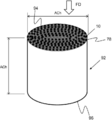
도 8은 본원에 기재된 바와 같은 흡착 카트리지의 등척도를 나타낸다.Figure 8 shows an isometric view of an adsorption cartridge as described herein.
도 9는 본원에 기재된 흡착재 제조의 공정 모식도를 나타낸다.Figure 9 shows a process schematic diagram of the sorbent preparation described herein.
도 10은 나일론 스페이서 링 및 밀봉재를 갖는 평행 통과 접촉기 또는 흡착 팩의 한 구현예를 나타낸다.10 shows one embodiment of a parallel pass contactor or adsorption pack having a nylon spacer ring and a seal.
도 11은 시험 또는 사용 동안 접촉기 또는 팩의 배치 및 제거를 보조하는 타이 로드를 갖는 평행 통과 접촉기 또는 흡착 팩의 하나의 구현예를 나타낸다. Figure 11 shows one embodiment of a parallel pass contactor or adsorption pack having a tie-rod that assists in the placement and removal of the contactor or pack during testing or use.
도 12는 일부 흡착제 부피가 제거되어(예시적 목적으로) 흡착 시트를 단단히 고정하는 스테이크를 노출시킨 자가 지지 흡착 카트리지이다.Figure 12 is a self-supporting adsorption cartridge in which a portion of the adsorbent volume has been removed (for illustrative purposes) to expose a stake that securely holds the adsorbent sheet.
상세한 설명details
본 발명의 특정한 예시적 구현예가 본원에 기재되며, 첨부 도면에서 예시된다. 기재된 구현예는 본 발명의 예시만을 위한 목적이며, 본 발명의 범위를 제한하는 것으로 간주되어서는 안 된다. 본 발명의 다른 구현예 및 기재된 구현예의 특정 개질, 조합 및 개선이 당분야 숙련자에게 일어날 것이며, 이러한 모든 대안적 구현예, 조합, 개질, 개선은 본 발명의 범위 내에 있다. 도면에 묘사된 구현예는 구현예이며 제한하는 것이 아니다. 본원에 기재된 구현예는 다중 종속항으로 기재된 것과 마찬가지로 임의의 적합한 조합으로 조합될 수 있는 것이다.Certain exemplary embodiments of the invention are described herein and illustrated in the accompanying drawings. The described embodiments are for purposes of illustration only and are not to be construed as limiting the scope of the invention. Specific modifications, combinations, and improvements of other embodiments and described implementations of the invention will occur to those skilled in the art, and all such alternative embodiments, combinations, modifications and improvements are within the scope of the present invention. The implementations depicted in the figures are illustrative and not restrictive. Embodiments described herein may be combined in any suitable combination as described in the multiple dependent claims.
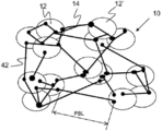
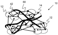
본 발명의 흡착재 10은 도 1a에 나타낸 바와 같이 중합체 결합제 14, 14'로 상호연결된 흡착 입자 12, 12'를 포함한다. 일부 중합체 결합제는 14'에 나타낸 바와 같이 흡착제의 양 표면과 접촉할 수 있고, 본원에 기재된 바와 같이 배향되지 않을 수 있다. 흡착재 10은 도 1a에 나타낸 바와 같이 흡착 입자를 접촉시키고 또 다른 흡착 입자 12'으로 연장되어 흡착 입자 12를 상호연결하는 중합체 결합제 14를 포함한다. 중합체 결합제 14는 도 1b에 나타낸 바와 같이 분기화될 수 있고, 여기서 중합체의 제1 부분은 둘 이상의 입자 사이에서 중합체의 제2 부분과 연결될 수 있다. 임의의 적합한 백분율의 흡착 입자가 본원에 기재된 바와 같은 중합체에 상호연결될 수 있다. 더 높은 농도의 흡착 입자는 개선된 흡착 성능을 제공할 수 있다. 하나의 구현예에서, 흡착재는 열 유도된 상 분리 공정으로 제조되며, 중합체 함량에 대한 질량 또는 부피가 독특하게 높은 백분율의 흡착 입자를 포함하고 상기 중합체와 상호연결된다. The
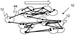
도 1a, 및 1b에 나타낸 바와 같이, 실질적으로 모든 흡착 입자가 중합체 결합제에 의해 상호연결된다. 또한, 도 1b에 나타낸 바와 같이, 일부 중합체 결합제는 배향 중합체 결합제 42이며, 여기서 이것은 흡착 입자 사이에서 연신되고 이를 상호연결하며, 적어도 2:1의 종횡비를 갖는다(배향 중합체의 길이는 도 1b에서 PBL로 나타낸다). 또한, 도 1c에서 흡착재의 단면 모식도에 나타낸 바와 같이, 배향 중합체 결합제는 실질적으로 동일한 방향으로 정렬되거나 배향되며, 대부분의 배향 중합체 결합제는 실질적으로 동일한 방향으로 연신된다. 본원에서 이용되는 실질적으로 동일한 방향은, 평균 배향 중합체 결합제 방향의 ±30도 각도 내를 의미한다. 도 1c에서 흡착재에 걸친 화살표는 재료의 가공 방향을 나타낸다. 중합체 결합제의 상기 정렬 배향은 재료의 가공 동안, 예컨대 압출, 가공 단계 사이의 롤에서 롤로의 이송 동안, 캘린더링 동안, 구성 채널 형성 동안 또는 흡착재가 연신될 수 있는 별도의 가공 단계 동안 부여될 수 있다. 부가적으로, 중합체 결합제는 종방향과 동일한 면으로 그러나 종방향에 수직으로 배향될 수 있다.As shown in Figs. 1A and 1B, substantially all adsorbent particles are interconnected by a polymeric binder. 1B, some of the polymeric binders are oriented
임의 수 및 유형의 흡착 입자가 이용될 수 있다. 흡착 입자는 임의의 적합한 형태 및 크기를 가질 수 있다. 하나 이상의 유형의 흡착 입자는 임의의 적합한 비 또는 중량 백분율로 흡착재 내에 도입될 수 있다. 흡착 입자는 비제한적으로 약 200um 이하, 약 100um 이하, 약 50um 이하, 약 25um 이하, 약 10um 이하, 약 5um 이하, 그리고 제공된 크기 치수를 포함하여 사이의 임의 범위를 포함하는 임의의 적합한 크기일 수 있다. 흡착 입자는 무기 화합물, 제올라이트, 활성탄, 수산화리튬, 수산화칼슘, 분자 체, 13X 등을 포함하여 임의 유형 또는 조합의 적합한 재료를 포함할 수 있다. 일부 구현예에서, 흡착 입자는 본질적으로 하나의 유형의 흡착재로 구성된다. Any number and type of adsorbent particles may be used. The adsorbent particles may have any suitable shape and size. One or more types of adsorbent particles may be introduced into the sorbent material at any suitable ratio or weight percent. The adsorbent particles can be any suitable size including, but not limited to, any range between about 200 .mu.m and about 100 .mu.m, about 50 .mu.m or less, about 25 .mu.m or less, about 10 .mu.m or less, about 5 .mu.m or less, have. The adsorbent particles may comprise any suitable type or combination of suitable materials including inorganic compounds, zeolites, activated carbon, lithium hydroxide, calcium hydroxide, molecular sieves, 13X, and the like. In some embodiments, the adsorbent particles consist essentially of one type of sorbent material.
중합체 결합제는 비제한적으로 열가소제, 가용성 중합체, 초고분자량 중합체, 초고분자량 폴리에틸렌, 폴리테트라플루오로에틸렌, 우레탄, 엘라스토머, 플루오로엘라스토머 등을 포함하는 임의의 적합한 유형 또는 조합의 재료일 수 있다. 배향 중합체 결합제는 흡착재의 강도를 크게 증가시킬 수 있다. 본원에서 정의된 바와 같이, 비제한적으로 적어도 약 10%, 적어도 약 40%, 적어도 약 50%, 적어도 약 60%, 적어도 약 70%, 그리고 제공된 값을 포함하여 사이의 임의 범위를 포함하는 임의의 적합한 백분율의 중합체 결합제가 배향될 수 있다. 하나의 구현예에서, 중합체 결합제는 실질적으로 배향되며, 여기서 적어도 70%의 중합체가 도 1b에 나타낸 바와 같이 배향된다. 배향 중합체는 비제한적으로 약 2:1 초과, 약 3:1 초과, 약 5:1 초과, 약 10:1 초과, 약 25:1 초과, 약 40:1 초과, 약 50:1 초과, 약 100:1 초과, 그리고 제공된 종횡비를 포함하여 사이의 임의 범위를 포함하는 임의의 적합한 종횡비를 가질 수 있다. 또한, 배향 중합체는 비제한적으로 약 2um 이하, 약 1um 이하, 약 0.5um 이하, 그리고 제공되는 치수를 포함하여 사이의 임의 범위를 포함하는 임의의 적합한 지름 또는 최대 횡길이 치수를 가질 수 있다. The polymeric binder may be any suitable type or combination of materials including, but not limited to, thermoplastics, soluble polymers, ultra high molecular weight polymers, ultra high molecular weight polyethylene, polytetrafluoroethylene, urethanes, elastomers, fluoroelastomers, The oriented polymeric binder can greatly increase the strength of the sorbent material. Including any range between, including, but not limited to, at least about 10%, at least about 40%, at least about 50%, at least about 60%, at least about 70% A suitable percentage of the polymeric binder can be oriented. In one embodiment, the polymeric binder is substantially oriented, wherein at least 70% of the polymer is oriented as shown in Figure 1b. The orientation polymer may include, but is not limited to, greater than about 2: 1, greater than about 3: 1, greater than about 5: 1, greater than about 10: 1, greater than about 25: 1, greater than about 40: : ≫ 1, and any aspect ratio between, including the aspect ratio provided. In addition, the oriented polymer may have any suitable diameter or maximum transverse dimension, including any range between, including, but not limited to, no greater than about 2 um, no greater than about 1 um, no greater than about 0.5 um, and dimensions provided.
흡착재의 중합체 함량은 비제한적으로 약 10% 이하, 약 8% 이하, 약 5% 이하, 약 4% 이하, 약 3% 이하, 약 2% 이하, 약 1% 이하, 약 0.6% 이하, 그리고 제공되는 임의의 중량 백분율을 포함하여 사이의 임의 범위를 포함하는 임의의 적합한 중량 백분율일 수 있다. 저농도의 중합체는 속도 및 양을 포함하여 흡착능을 증가시킬 수 있는 더 고농도의 흡착 입자를 의미한다.The polymer content of the sorbent material is, but is not limited to, about 10%, about 8%, about 5%, about 4%, about 3%, about 2%, about 1% Including any range between, including, but not limited to, any weight percentages. A low concentration polymer means a higher concentration of adsorbent particles which can increase the adsorption capacity including the rate and amount.
흡착재 10은 다공성으로, 구조 내로의 기체 확산을 허용하여 특정 기체 분자가 흡착 입자에 의해 흡착될 수 있게 한다. 흡착제는 비제한적으로 약 5% 초과, 약 10% 초과, 약 20% 초과, 약 30% 초과, 약 50% 초과, 약 60% 초과, 약 70% 초과, 약 80% 초과, 약 90% 초과, 약 95% 초과, 그리고 제공되는 백분율을 포함하여 사이의 임의 범위를 포함하는 임의의 적합한 다공성을 가질 수 있다. 흡착재는 비투과성으로, 재료를 통한 벌크 기류를 실질적으로 갖지 않을 수 있다. 예를 들어 하나의 구현예에서, 흡착재는 본원에서 정의된 바와 같이 100초 초과, 또는 25초 초과, 또는 50초 초과, 또는 200초 초과, 또는 300초 초과, 또는 400초 초과의 걸리 덴소미터 모델 4340의 자동 걸리 덴소미터 시간을 갖는 시트이다. 일부 구현예에서, 흡착 시트는 100초 미만의 감소된 걸리 시간을 가질 수 있다(예로 일부 구현예에서, 시트는 흡착 입자 간 거리까지 개방될 수 있는 강화 섬유를 포함할 수 있다). 본원에 기재된 흡착 시트는 중합체 결합제에 의해 상호연결된 흡착 입자의 다공성 구조를 가지며 자가 지지성이다. 흡착재에 대해 본원에서 이용되는 용어 자가 지지성이란 재료가 자립하거나 서로 떨어지지 않고 취급될 수 있음을 의미한다. 예를 들어, 흡착 팩 층은 흡착 입자가 느슨하고 일부 외부 강화 또는 하우징을 필요로 하므로 자가 지지성이 아닐 것이다. The
하나의 크기의 구를 패킹하기 위한 최대 이론 패킹은 64%(36% 공극)이다. 4 내지 8메쉬 비드 체 크기의 13X 분자 체 비드를 사용하는 당분야 숙련자는 패킹 층에서의 적절한 비드 충전으로 약 40%의 비드 간 공극 부피를 달성할 수 있음을 안다. 본 발명의 구 또는 흡착제를 제조하기 위한 미세 분말의 패킹 밀도는 일어나는 압축 또는 가공의 양에 따라, 또한 입자 간 공극 부피를 변화시키는 입자의 형태 및 크기에 따라 변한다.The maximum theoretical packing for packing one size of sphere is 64% (36% void). Those skilled in the art using 13X molecular sieve beads of 4 to 8 mesh bead body size know that an appropriate bead fill in the packing layer can achieve an inter-bead void volume of about 40%. The packing density of the fine powder for producing the spheres or adsorbents of the present invention varies depending on the amount of compression or processing that takes place and also on the shape and size of the particles which change the intergranular void volume.
수산화칼슘 시트를 제조하기 위해 초고분자량 폴리에틸렌의 열 유도된 상 분리를 이용한 시험에서, 추출 전 오일 함량으로 결정되는 입자 간 공극 공간은 68.0% 공극 공간이다. 그러나 상기 오일을 용매로 추출하고 용매를 가열 및 제거한 후, 흡착 시트는 18.3부피% 수축한다. 수산화칼슘 분말의 최대 패킹 밀도가 40%의 공극 부피를 갖는 경우, 68% 공극 공간으로 시작했다면 최대 패킹 밀도를 초과하는 28% 추가 공극 부피가 형성된다. 흡착 시트의 총 부피가 18% 수축하고, 이것이 추가 공극 부피의 감소에 의해서만 달성될 수 있는 경우, 18%를 초기의 28% 추가 공극 부피로 나누면 추가 공극 부피가 64% 수축된다. 이러한 수축으로도 증가된 입자 간 공극 부피가 여전히 달성된다. 일부 구현예에서, 섬유 강화는 추가 공극 부피 수축을 감소시키고, 입자 간 공간을 개방시키고 흡착 구조에서 기체의 거시적 확산을 개선한다. 이는 감소된 걸리 수 그리고 상기 흡착 시트에 함유된 흡착 입자의 증가된 이용을 갖는 흡착제를 생성할 수 있다.In tests using thermally induced phase separation of ultra high molecular weight polyethylene to prepare calcium hydroxide sheets, the interparticulate void space determined by the oil content before extraction is 68.0% void space. However, after extracting the oil with a solvent and heating and removing the solvent, the adsorbent sheet shrinks by 18.3% by volume. If the maximum packing density of the calcium hydroxide powder has a pore volume of 40%, then starting with 68% void space will result in a 28% additional pore volume exceeding the maximum packing density. If the total volume of the adsorbent sheet shrinks by 18% and this can only be achieved by a reduction in the extra pore volume, dividing the 18% by the initial 28% additional pore volume will result in an additional pore volume of 64% shrinkage. Even with this shrinkage, increased interparticle void volume is still achieved. In some embodiments, the fiber reinforcement reduces additional void volume shrinkage, opens intergranular voids, and improves the macroscopic diffusion of the gas in the adsorption structure. This can produce an adsorbent having reduced Gurley number and increased utilization of adsorbent particles contained in the adsorbent sheet.
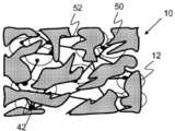
흡착 시트는 도 2a 및 2b에 묘사된 바와 같이 적어도 하나의 표면 상에 구성 흡착 보유 층 50을 추가로 포함할 수 있고, 양 표면 상에 있을 수도 있다. 하나의 구현예에서, 구성 흡착 보유 층은 본원에 기재된 구성 채널의 표면 내에 있지 않다. 구성 흡착 보유 층은 흡착 시트 표면 상의 박층 재료이다. 도 2a 및 도 2b에 나타낸 바와 같이, 구성 흡착 보유 층 50은 매우 얇고 구성 흡착 보유 층의 부분 간 개구 52를 가지며 불연속적이다. 개구 52는 도 2b에 묘사된 바와 같이 연속적이고/이거나 개별일 수 있고, 여기서 이들은 구성 흡착 보유 층에서의 홀과 같이 구성 흡착 보유 층의 외부 경계에 의해 정의된다. 구성 흡착 보유 층은 스며든 중합체 결합재 및 흡착재를 포함할 수 있다. 하나의 구현예에서, 구성 흡착 보유 층은 본질적으로 중합체 결합제로 구성되며 박막층의 중합체 결합제가 스며들거나 이를 포함할 수 있다. 구성 흡착 보유 층은 비제한적으로 약 90% 이하, 약 80% 이하, 약 70% 이하, 약 60% 이하, 약 50% 이하, 약 40% 이하, 그리고 제공된 임의의 백분율을 포함하여 사이의 임의 범위를 포함하는 임의의 적합한 백분율의 흡착재 표면을 폐색할 수 있다. 구성 흡착 보유 층은 비제한적으로 약 100um 이하, 약 50um 이하, 약 25um 이하, 약 10um 이하, 약 5um 이하, 약 3um 이하, 약 2um 이하, 약 1um 이하, 그리고 제공된 임의의 개구 크기를 포함하여 사이의 임의 범위를 포함하는, 임의의 적합한 공칭 개구 크기를 갖는 개구 52를 포함할 수 있다. 구성 흡착 보유 층은 비제한적으로 약 5um 이하, 약 3um 이하, 약 2um 이하, 약 1um 이하, 약 0.75um 이하, 약 0.5um 이하, 그리고 제공된 두께 값을 포함하여 사이의 임의 범위를 포함하는 임의의 적합한 두께를 가질 수 있다. The adsorbent sheet may further comprise a constituent
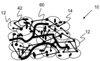
일부 구현예에서, 흡착재는 도 3a 및 3b에 묘사된 바와 같이 흡착재 내로 도입될 수 있는 강화 섬유 60을 추가로 포함할 수 있다. 강화 섬유는 구성 흡착 보유 층 내를 포함하여 흡착제의 임의 부분 내로 도입될 수 있다. 도 3a의 표면 모식도에 묘사된 바와 같이, 강화 섬유는 흡착재 내에 배치되고 중합체 결합제 및 흡착 입자와 뒤엉킬 수 있다. 강화 섬유는 흡착재 시트의 한 면 내에, 예컨대 하나의 표면 상에 농축될 수 있다. 도 3b에 나타낸 바와 같이, 단면 모식도는 흡착재의 두께를 통해 연장하는 강화 섬유를 나타낸다. 강화 섬유는 흡착재의 농도 구배를 가질 수 있다, 예컨대 표면 상에 및 또는 흡착재 두께의 중심 내에 농축된다. 강화 섬유는 흡착재의 기계적 강도 및 내구성을 증가시킬 수 있다. 예를 들어, 압축 강도는 분말 입자 간 거리를 증가시켜 흡착재 밀도를 감소시키고 흡착 입자 간 거시적 확산 저항을 감소(입자 간 공극 공간을 증가시켜)시키는 경우에도 강화 섬유로 개선될 수 있다. In some embodiments, the sorbent material may further include a reinforcing
임의의 적합한 양의 강화 섬유가 흡착재 내에 포함될 수 있고, 비제한적으로 약 50% 이하, 약 40% 이하, 약 30% 이하, 약 20% 이하, 약 10% 이하, 약 5% 이하, 약 2% 이하, 약 1% 이하, 그리고 제공된 중량 백분율을 포함하여 사이의 임의 범위를 포함하는 임의의 적합한 중량 백분율의 흡착재를 포함할 수 있다. 강화 섬유는 임의의 적합한 길이 및 횡길이 치수, 예컨대 지름 또는 폭을 가질 수 있다. 강화 섬유의 길이는 비제한적으로 약 0.01mm 이하, 약 0.05mm 이하, 약 0.10mm 이하, 약 0.25mm 이하, 약 0.5mm 이하, 약 0.75mm 이하, 약 1mm 이하, 약 2mm 이하, 약 4mm 이하, 약 8mm 이하, 그리고 제공된 길이를 포함하여 사이의 임의 범위를 포함하는 임의의 적합한 길이일 수 있다. 폭 또는 최대 횡길이 치수는 비제한적으로 약 0.1um 이하, 약 1um 이하, 약 5um 이하, 약 20um 이하, 약 50um 이하, 약 100um 이하, 약 500um 이하, 그리고 제공된 길이를 포함하여 사이의 임의 범위를 포함하는 임의의 적합한 치수일 수 있다. 강화 섬유는 혼합 공정 동안, 압출 공정 동안, 캘린더링 공정 동안 등을 포함하여 흡착재의 제조 공정에서 임의의 적합한 시점에 첨가될 수 있다. Any suitable amount of reinforcing fibers may be included in the sorbent material and may include, but is not limited to, not more than about 50%, not more than about 40%, not more than about 30%, not more than about 20%, not more than about 10%, not more than about 5% , Less than about 1%, and any range between, inclusive of the weight percentages provided. The reinforcing fibers may have any suitable length and transverse dimension, e.g., diameter or width. The length of the reinforcing fibers is at least about 0.01 mm, less than about 0.05 mm, less than about 0.10 mm, less than about 0.25 mm, less than about 0.5 mm, less than about 0.75 mm, less than about 1 mm, less than about 2 mm, less than about 4 mm, About 8 mm or less, and any length between, including the length provided. The width or maximum transverse dimension may be any range between and including, but not limited to, about 0.1 um, about 1 um, about 5 um, about 20 um, about 50 um, about 100 um, about 500 um, And may be any suitable dimension including. The reinforcing fibers may be added at any suitable point in the process of making the sorbent during the mixing process, during the extrusion process, during the calendering process, and the like.
흡착재 10은 도 4a 및 4b에 나타낸 바와 같이, 제1 표면 72 및 제2 표면 74 그리고 비제한적으로 약 1mm 이하, 약 2mm 이하, 약 4mm 이하, 약 6mm 이하, 그리고 제공된 두께 값을 포함하여 사이의 임의 범위를 포함하는 임의의 적합한 두께 ASt를 갖는 시트 70으로 형성될 수 있다. 흡착 시트는 약 3미터 초과, 약 10m 초과, 약 100m 초과, 약 1.000m 초과, 그리고 제공된 길이를 포함하여 사이의 임의 범위의 길이를 갖는 재료의 연속 시트일 수 있다. The
흡착 시트는 동일하거나 상이한 치수를 갖는 복수의 구성 채널 80을 포함할 수 있다. 채널은 도 4b에 묘사된 바와 같이 임의의 적합한 폭 Cw 및 깊이 Cd를 가질 수 있다. 리브 82는 도 4b에 묘사된 바와 같이 채널을 분리할 수 있다. 본원에서 이용되는 구성 채널은 흡착 팩 또는 카트리지 안팎으로의 유로를 나타낸다. 일부 구현예에서, 추가적인 스페이서가 필요하지 않을 수 있다. 도 6a 및 6b에 나타낸 바와 같이, 하나의 구현예에서, 채널은 시트의 한 면에만 있고, 또 다른 구현예에서, 채널은 시트의 양 면에 있다. 채널은 도 4a에 나타낸 바와 같이 흡착 시트 70의 가공 방향 Pd로 정렬될 수도 있고, 또는 도 5에 나타낸 바와 같이 가공 방향 Pd에 각을 갖고 구성될 수도 있다. 채널은 가공 방향에 대해 임의의 적합한 배향으로, 예컨대 가공 종방향으로 또는 횡방향으로 구성될 수 있다. 채널은 선형일 수 있고 또는 곡선일 수 있고 또는 적어도 일부가 곡선으로 구성될 수도 있다. 채널은 분기화될 수도 있고, 재료의 길이를 따라 서로 교차할 수도 있다. 채널은 비제한적으로 시트 전체 두께의 약 20% 초과, 약 40% 초과, 약 50% 초과, 약 60% 초과, 약 70% 초과, 약 80% 초과, 그리고 제공된 백분율을 포함하여 사이의 임의 범위를 포함하는 임의의 적합한 백분율의 깊이를 가질 수 있다. 채널은 비제한적으로 약 0.5:1 초과, 약 0.75:1 초과, 약 1:1 초과, 약 1.5:1 초과, 약 2:1 초과, 약 3:1 초과, 약 4:1 초과, 그리고 제공된 비를 포함하여 사이의 임의 범위를 포함하는 임의의 적합한 비의 폭 대 깊이 치수를 가질 수 있다. 본원에 기재된 임의 수의 상이한 구성의 채널 및 조합 구성이 의도된다. The adsorbent sheet may comprise a plurality of
본원에 기재된 흡착재는 도 7 및 도 8에 각각 나타낸 높이 및 지름을 갖는 흡착 카트리지 92를 포함하는 흡착 팩 90으로 제조될 수 있다. 도 7에 나타낸 바와 같이, 흡착 시트 70은 적층되어 구성 채널 80을 갖고 하우징 100 내에 배치되는 흡착 팩 90을 형성한다. 도 8에 나타낸 바와 같이, 흡착 카트리지 92는 권취된 흡착재 10의 연속 시트 78로부터 구축되었다. 화살표로 도 8에 나타낸 바와 같이, 흐름 방향 FD를 카트리지의 입구 94 및 출구 96에 나타낸다. 흡착 팩 또는 카트리지는 흡착되는 제1 기체 및 흡착되지 않는 제2 기체를 갖는 유체를 구성 채널을 통해 통과시켜 기체를 농축하는데 이용될 수 있다. 흡착재는 특정 기체 분자만을 흡착하거나, 특정 기체 분자를 더 많이 또는 더 높은 속도로 흡착하도록 선택될 수 있다. The adsorbent material described herein may be manufactured as an
도 12는 여러(도 12에 묘사된 구현예에서는 8개) 스테이크 142 및 143이 흡착 카트리지 내로 구동되어 화학 반응성 흡착 시트를 함께 단단히 유지하는 흡착 시트 30을 함유하는 자가 지지 흡착 카트리지 141의 구현예를 나타낸다. 단속선으로 경계를 나타낸 부피 145가 도 12에서 흡착 카트리지 141로부터 제거되어 스테이크 142 및 143을 노출한다. 이들 스테이크는 주변 시트에 대해 각각의 시트를 동시에 유지하면서 카트리지가 그 정확한 외부 치수를 유지할 수 있도록 한다. 대안적으로, 흡착 시트는 스테이플 또는 스테이플들, 선, 막대(들), 코드, 리벳(들) 또는 탄성 재료로 스테이크 처리될 수 있다. 강성 스테이크를 갖는 카트리지는 슬리브가 흡착 카트리지의 공기 입구 및 출구 면 146, 147을 덮지 않도록 얇은 중합체 슬리브로 추가 랩핑될 수 있다. 이러한 얇은 슬리브는 최종 사용자가 흡착 화학물질과 접촉하는 것을 방지한다. 슬리브는 흡착 카트리지를 함께 유지하기 위한 조임력을 전혀 또는 거의 제공하지 않는다. 12 illustrates an embodiment of a self supporting
일부 구현예에서, 중합체 시트는 카트리지를 랩핑하지 않는다. 스테이크는 시트 대 시트 접촉이 유지되도록 시트를 강하게 유지한다. 도 12에 나타낸 바와 같이, 스테이크 142는 유로 144로 수직 삽입되고, 유로 144에 대해 90도까지의 각도로 하나의 스테이크 또는 여러 스테이크들 143을 삽입하여 추가적인 카트리지 안정성이 달성될 수 있으며, 이는 카트리지의 굴곡을 감소시키거나 배제한다. 카트리지 141의 공기 입구면 146 및 공기 출구면 147은 흐름 방향 144가 역전되기 위해 역전될 수 있다. 카트리지 141은 양 방향에서 기류에 대해 유사하게 작용한다. In some embodiments, the polymer sheet does not wrap the cartridge. The stakes strongly hold the sheet to maintain sheet-to-sheet contact. 12, the
카트리지 141이 캐니스터 내로 설치되는 경우, 카트리지 141은 밀봉을 허용하도록 카트리지의 네 면 상에 중합체 폼 랩핑을 추가로 포함할 수 있다. 중합체 폼은 스스로 또는 중합체 랩핑 상부 또는 하부에 설치될 수 있다.When the
본 발명의 흡착재 및 팩은 임의의 적합한 가공 단계 세트를 통해 제조될 수 있다. 하나의 구현예에서, 흡착재는 하기 단계들을 포함하는, 도 9에 나타낸 바와 같은 열 유도된 상 분리 공정에 의해 제조된다: 승온에서 제1 용매 중에 중합체 결합제를 용해하여 혼합물을 형성하고, 흡착 입자를 중합체 혼합물에 첨가 및 혼합하여 흡착 슬러리를 형성하고, 흡착 슬러리를 시트화 다이를 통해 압출하여 압출물 또는 시트를 형성하고, 압출물을 냉각하여 열 유도된 상 분리를 일으키고, 압출물에 구성 채널을 형성하고, 상기 압출물에서 제1 용매를 추출하여 구성 채널을 갖는 흡착 시트를 형성함. 용매는 선택된 중합체를 용해시키도록 임의의 적합한 온도로 가열될 수 있다. The sorbents and packs of the present invention can be made through any suitable set of processing steps. In one embodiment, the sorbent material is made by a heat-induced phase separation process as shown in Figure 9, comprising the steps of: dissolving the polymeric binder in a first solvent at elevated temperature to form a mixture, Adding and mixing to the polymer mixture to form an adsorbent slurry, extruding the adsorbent slurry through a sheeting die to form an extrudate or sheet, cooling the extrudate to cause thermally induced phase separation, And extracting the first solvent from the extrudate to form an adsorption sheet having a constituent channel. The solvent may be heated to any suitable temperature to dissolve the selected polymer.
구성 채널은 임의의 적합한 공정을 통해 흡착 시트에 형성될 수 있다. 예를 들어, 압출물은 시트가 이를 통과할 때 여기에 구성 채널을 형성하는 프로필을 갖는 캘린더링 롤러를 통해 통과될 수 있다. 또 다른 구현예에서, 개별 시트가 압반으로 압축되어 구성 채널을 형성할 수 있다. 또 다른 구현예에서, 구성 채널은 이것이 건조되기 전 또는 후에 흡착 시트로 가공될 수 있다. 예를 들어, 일련의 연마 휠을 이용하여 시트 및 내부에서 흡착재를 제거하여 구성 채널을 갖는 흡착 시트를 형성할 수 있다.The constituent channels can be formed in the adsorption sheet through any suitable process. For example, the extrudate may be passed through a calendering roller having a profile that forms a constituent channel here when the sheet passes therethrough. In another embodiment, the individual sheets can be platen platen to form the constituent channels. In another embodiment, the constituent channels may be processed into a sorbent sheet before or after it is dried. For example, a series of abrasive wheels can be used to remove adsorbent material from the sheet and from inside to form adsorbent sheets having constituent channels.
물품의 한 구현예를 입구 온도, 출구 온도, 상이한 압력, 압력 이슬점(칠드 미러 습도계), 입구 압력, 출구 압력 및 유속의 중요 시험 파라미터를 캡처하는 ISO 7183 표준을 이용하는 압력 전환 흡착 사이클 시험에서 시험하였다. 시험 장치는 도 11과 유사하며, 물품은 열 유도된 상 분리 공정을 통해 제조된 초고분자량 폴리에틸렌 결합제 및 13x 분자 체로부터 형성된 리브를 갖는 나선 권취된 흡착 시트이다. One embodiment of the article was tested in a pressure switched adsorption cycle test using the ISO 7183 standard which captures key test parameters of inlet temperature, outlet temperature, differential pressure, pressure dew point (chilled mirror hygrometer), inlet pressure, outlet pressure and flow rate . The test apparatus is similar to that of Fig. 11, wherein the article is a spirally wound adsorbent sheet having a ultra-high molecular weight polyethylene binder made through a heat-induced phase separation process and a rib formed from a 13x molecular sieve.
PSA 장비(모이스처 장비 상의 내구성 시험)에서, 단위를 약 200,000 사이클 완료하고 안정된 이슬점(전형적으로 -37℃ PDP)을 유지하였다.In PSA equipment (durability test on the moisture equipment), the unit completed approximately 200,000 cycles and maintained a stable dew point (typically -37 ° C PDP).
신속 사이클 장비에서, 실제적인 가시적 손상이나 이슬점, 흐름 및 기계적 안정성의 열화 없이 단위를 1,000,000 사이클 완료했으며, 이는 예상치 못한 것이었고 7Bar 압력 전환 사이클의 전형적 13x 분자 체 4 내지 8 메쉬 비드에 비해 개선이다. 우연한 침수 후에도, 단위는 퍼징 후에 최적 성능을 재수득할 수 있었으며, 이 또한 예상치 못한 것으로 이것이 현재 업계 표준인 표준 13x, 4 내지 8 메쉬 비드 이용 시 일어났다면 시스템 정지 및 흡착제 제거를 필요로 했을 것이다. In fast-cycle equipment, the unit completed 1,000,000 cycles without substantial visible damage or degradation of dew point, flow, and mechanical stability, which was unexpected and improved compared to the typical 13x molecular sieve 4-8 mesh beads in the 7Bar pressure conversion cycle. Even after accidental immersion, the unit could re-acquire optimal performance after purging, which is also unexpected and would have required system shutdown and desorbent removal if this happened with current industry standard 13x, 4 to 8 mesh beads.
순환 시험에서, 결과는 압력/온도(PTSA) 시험 동안 단위의 일관된 흡착/탈착 성능을 시사하였다. 침수 후의 신속한 평형(안정 상태 조건) 개시는 예상치 못한 것이었고, 다른 13X 분자 체 기반 시스템에 비해 잠재적인 개선이다. In the cyclic test, the results indicated consistent adsorption / desorption performance of the unit during the pressure / temperature (PTSA) test. The rapid equilibrium (steady state) initiation after immersion was unexpected and is a potential improvement over other 13X molecular sieve based systems.
당분야 숙련자에게는 본 발명의 요지 또는 범위를 벗어나지 않고 다양한 개질, 조합 및 변형이 본 발명에서 수행될 수 있음이 자명할 것이다. 본원에 기재된 특정 구현예, 특징 및 성분은 임의의 적합한 방식으로 개질되고/되거나 조합될 수 있다. 따라서 본 발명은 첨부되는 특허청구범위 및 이들의 균등 범위 내에 일어나는 한, 본 발명의 개질, 조합 및 변형을 포괄하는 것이다.It will be apparent to those skilled in the art that various modifications, combinations, and alterations can be made herein without departing from the spirit or scope of the invention. The specific embodiments, features, and components described herein may be modified and / or combined in any suitable manner. Accordingly, it is intended that the present invention cover modifications, combinations, and variations of this invention provided they come within the scope of the appended claims and their equivalents.
본원에서 이용되는 연속 시트는 종방향 및 횡방향을 갖고 긴 길이로 제조될 수 있는 재료의 시트로 정의되며, 여기서 종방향은 약 3m 초과, 약 10m 초과, 약 100m 초과, 약 1000m 초과, 또는 제공된 임의의 길이를 포함하여 사이의 길이를 가질 수 있다. The continuous sheet used herein is defined as a sheet of material that can be produced in longitudinal and transverse directions and in which the longitudinal direction is greater than about 3 meters, greater than about 10 meters, greater than about 100 meters, greater than about 1000 meters, But may have a length of between, including any length.
본원에서 이용되는 가공 방향은 재료의 종방향 또는 횡방향과 실질적으로 평행한 방향으로 정의된다.The processing direction used herein is defined as a direction substantially parallel to the longitudinal or transverse direction of the material.
흡착재에 대해 본원에서 이용되는 실질적으로 비투과성이란 재료를 통한 기류가 실질적으로 없음을, 예컨대 100초 초과의 걸리 값을 가짐을 의미한다.As used herein, substantially impermeable to the sorbent means that there is substantially no airflow through the material, such as a gull value of greater than 100 seconds.
본원에서 이용되는 배향 중합체 결합제는 흡착 입자 사이에서 연신되고 이를 상호연결하며, 적어도 2:1의 종횡비를 갖는 중합체 결합제로 정의된다.The oriented polymeric binder used herein is defined as a polymeric binder that stretches between and interconnects the adsorbent particles and has an aspect ratio of at least 2: 1.
배향 중합체 결합제에 대해 본원에서 이용되는 종횡비는 폭에 걸친 길이의 비 또는 길이의 중심 30% 내의 최대 횡길이 치수를 나타낸다. The aspect ratio used herein for the oriented polymeric binder represents the ratio of the length across the width or the maximum transverse dimension within the
배향 중합체 결합제의 최대 횡길이 치수는 길이의 중심 30%를 초과하는 최대 치수, 폭, 지름 등이다. 상기 값을 측정하기 위해, 배향 중합체 결합제의 길이를 측정하고, SEM 이미지 상에서 중심을 확인한 뒤 길이의 중심 30%에 걸쳐 측정하여 최대 치수를 결정한다. The maximum transverse dimension of the oriented polymeric binder is the largest dimension, width, diameter, etc., greater than 30% of the center of the length. To measure this value, determine the maximum dimension by measuring the length of the oriented polymeric binder, determining the center on the SEM image, and then measuring over the
본원에서 이용되는, 본질적으로 배향 중합체 결합제로 구성된 중합체 결합제는 대부분의 중합체 결합제가 흡착 입자 사이에서 연신되고 이를 상호연결하며 적어도 2:1의 종횡비를 가짐을 의미한다.
As used herein, a polymeric binder consisting essentially of an oriented polymeric binder means that most of the polymeric binder is drawn between the adsorbent particles and interconnects them and has an aspect ratio of at least 2: 1.
Claims (45)
상기 하나 이상의 흡착 시트들이 흡착 입자들 및 폴리에틸렌 결합제를 포함하고;
상기 시트 내의 상기 흡착 입자들이 하나 이상의 유형들일 수 있고, 흡착 입자들의 각 유형은 200nm 초과의 평균 입자 크기를 갖는 시스템.Pressure swing adsorption (PSA) comprising a parallel pass contactor structure comprising one or more self-supporting adsorption sheets arranged in multiple overlapping layers mechanically arranged to allow airflow between the layers from one end of the structure to another, A system for temperature switched adsorption (PTSA), or vacuum pressure switched adsorption (VPSA)
Wherein the at least one adsorbent sheet comprises adsorbent particles and a polyethylene binder;
Wherein the adsorbent particles in the sheet can be one or more types and each type of adsorbent particles has an average particle size of greater than 200 nm.
The system of any of claims 19 to 44, comprising parallel pass contactor structures.
Applications Claiming Priority (3)
| Application Number | Priority Date | Filing Date | Title |
|---|---|---|---|
| US201261637517P | 2012-04-24 | 2012-04-24 | |
| US61/637,517 | 2012-04-24 | ||
| PCT/US2013/037776 WO2013163167A1 (en) | 2012-04-24 | 2013-04-23 | Durable adsorbent material and adsorbent packs |
Publications (1)
| Publication Number | Publication Date |
|---|---|
| KR20150014466A true KR20150014466A (en) | 2015-02-06 |
Family
ID=49378903
Family Applications (1)
| Application Number | Title | Priority Date | Filing Date |
|---|---|---|---|
| KR1020147032989A KR20150014466A (en) | 2012-04-24 | 2013-04-23 | Durable adsorbent material and adsorbent packs |
Country Status (6)
| Country | Link |
|---|---|
| US (1) | US9266054B2 (en) |
| EP (2) | EP4245399A1 (en) |
| KR (1) | KR20150014466A (en) |
| CA (1) | CA2871447A1 (en) |
| IN (1) | IN2014DN09775A (en) |
| WO (1) | WO2013163167A1 (en) |
Families Citing this family (22)
| Publication number | Priority date | Publication date | Assignee | Title |
|---|---|---|---|---|
| US8821619B2 (en) | 2010-10-14 | 2014-09-02 | Micropore, Inc. | Adsorbent cartridge assembly with end cap |
| GB201110868D0 (en) * | 2011-06-27 | 2011-08-10 | Jones Susan H | Zeolites and composites incorporating zeolites |
| KR101559902B1 (en) * | 2013-08-12 | 2015-10-14 | (주)세프라텍 | Gas separation system using adsorptive permeation hollow fiber membrane |
| EP3229938A1 (en) | 2014-12-10 | 2017-10-18 | ExxonMobil Research and Engineering Company | Adsorbent-incorporated polymer fibers in packed bed and fabric contactors, and methods and devices using same |
| FR3035196A1 (en) * | 2015-04-17 | 2016-10-21 | Air Liquide | ADSORBENT PLATE STRUCTURE |
| US10156373B1 (en) | 2015-05-15 | 2018-12-18 | The United States Of America, As Represented By The Secretary Of The Navy | Thermal integration of a catalytic burner and a carbon dioxide removal unit |
| US10828620B2 (en) * | 2015-07-09 | 2020-11-10 | Ingevity South Carolina, Llc | Gaseous storage system, methods for making and using the same |
| WO2017147736A1 (en) * | 2016-02-29 | 2017-09-08 | Honeywell International Inc. | Air filtration media and method of processing the same |
| GB2551310B8 (en) * | 2016-05-24 | 2020-01-22 | Thomas Billet Colin | A gas treatment element and a method of forming a gas treatment element |
| US10035098B2 (en) | 2016-06-13 | 2018-07-31 | Hamilton Sundstrand Corporation | Cartridge for mounting lithium hydroxide sheets |
| EP3554685A4 (en) | 2016-12-16 | 2020-07-22 | Flow Dry Technology, Inc. | Solid form adsorbent |
| CA3045034C (en) * | 2016-12-21 | 2021-06-29 | Exxonmobil Upstream Research Company | Self-supporting structures having active materials |
| JP7333753B2 (en) | 2017-01-31 | 2023-08-25 | カルゴン カーボン コーポレーション | adsorption device |
| US10843117B2 (en) * | 2018-05-25 | 2020-11-24 | Ford Motor Company | Active carbon filter for a carbon canister and a method for producing the same |
| US11697580B2 (en) | 2018-08-01 | 2023-07-11 | Calgon Carbon Corporation | Apparatus for hydrocarbon vapor recovery |
| EP3829747A4 (en) | 2018-08-02 | 2022-03-30 | Calgon Carbon Corporation | Sorbent devices |
| WO2020028845A1 (en) | 2018-08-02 | 2020-02-06 | Calgon Carbon Corporation | Sorbent devices |
| US10946161B2 (en) | 2018-12-05 | 2021-03-16 | Aires Medical LLC | Pulsed pressure swing adsorption system and method |
| CN111377404B (en) * | 2018-12-27 | 2021-07-09 | 中国石油化工股份有限公司 | Memory, method, device and equipment for determining optimal adsorption time of pressure swing adsorption |
| CN111589224A (en) * | 2019-02-20 | 2020-08-28 | 中国石油化工股份有限公司 | Multistage filtering system and method for oil slurry |
| MX2022000840A (en) * | 2019-07-22 | 2022-03-17 | Calgon Carbon Corp | Textured sorbent sheets, assemblies containing them, and molds for making same. |
| US11904297B1 (en) | 2023-01-11 | 2024-02-20 | Iliad Ip Company, Llc | Process for manufacturing lithium selective adsorption/separation media |
Family Cites Families (98)
| Publication number | Priority date | Publication date | Assignee | Title |
|---|---|---|---|---|
| US2395842A (en) | 1930-07-14 | 1946-03-05 | Borgstrom Parry | Gas absorbent material and process of making the same |
| US2038071A (en) * | 1932-11-09 | 1936-04-21 | Patent Finance Corp | Fluid treating device |
| US2629652A (en) | 1946-04-03 | 1953-02-24 | William H Schechter | Porous anhydrous lithium hydroxide granules |
| US2837413A (en) | 1955-04-13 | 1958-06-03 | Air Reduction | Carbon dioxide absorber for anesthetic administering apparatus |
| US2812769A (en) | 1955-05-06 | 1957-11-12 | Engineering Dev Corp | Tents |
| US3034655A (en) | 1957-12-03 | 1962-05-15 | Otto H York | Reinforced mesh pad |
| US3489144A (en) | 1967-02-13 | 1970-01-13 | Gen Electric | Closed rebreather - respirator circuit for renovation and supply of oxygen/nitrogen gas mixture |
| US3604416A (en) | 1969-04-28 | 1971-09-14 | Universal Oil Prod Co | Emergency oxygen system |
| US3607040A (en) | 1969-04-28 | 1971-09-21 | Universal Oil Prod Co | Preparation of alkali metal hydroxide pellets |
| US3755535A (en) | 1971-09-16 | 1973-08-28 | Shell Oil Co | Process for the removal of sulfur trioxide from industrial off gases |
| US3847837A (en) | 1972-04-25 | 1974-11-12 | Foote Mineral Co | Carbon dioxide absorbent granules |
| US3860818A (en) | 1972-04-27 | 1975-01-14 | Texas Instruments Inc | Atmospheric pollution monitor |
| GB1429476A (en) | 1972-07-05 | 1976-03-24 | Secr Defence | Filter assemblies |
| US3909206A (en) | 1974-04-10 | 1975-09-30 | United Technologies Corp | High performance carbon dioxide scrubber |
| US3950157A (en) | 1974-10-07 | 1976-04-13 | Dorrance Henry Matney | Ram air filter for light aircraft |
| US4168706A (en) | 1977-03-24 | 1979-09-25 | Nasa | Portable breathing system |
| US4153661A (en) | 1977-08-25 | 1979-05-08 | Minnesota Mining And Manufacturing Company | Method of making polytetrafluoroethylene composite sheet |
| US4699681A (en) * | 1978-09-08 | 1987-10-13 | D-Mark, Inc. | Method of making a gas phase permeable filter |
| US4250172A (en) | 1979-02-09 | 1981-02-10 | Hausheer Hans P | Needled fiber mat containing granular agent |
| US4255175A (en) | 1979-10-12 | 1981-03-10 | American Air Filter Company, Inc. | Gas separation filter device having a handle |
| US4342811A (en) | 1979-12-28 | 1982-08-03 | Albany International Corp. | Open-celled microporous sorbent-loaded textile fibers and films and methods of fabricating same |
| US4409978A (en) | 1980-06-16 | 1983-10-18 | Portable Air Supply Systems, Corp. | Portable, self-contained breathing apparatus |
| US4342278A (en) | 1980-10-15 | 1982-08-03 | Horan John J | Miniature inflatable containment and dry-water-entry vessels |
| CA1151633A (en) | 1981-05-27 | 1983-08-09 | Clive D. R. Macgregor | Absorption of carbon dioxide |
| US4442162A (en) | 1981-10-09 | 1984-04-10 | Brunswick Corporation | Chemical and biological resistant material and method of fabricating same |
| GB2109268B (en) | 1981-11-16 | 1984-10-03 | Process Scient Innovations | Gas purifiers |
| JPS6044242B2 (en) | 1982-04-27 | 1985-10-02 | 株式会社星子療科研究所 | How to generate oxygen in an emergency |
| US4631872A (en) | 1983-01-12 | 1986-12-30 | Daroga Nader D | Nuclear blast and fall-out shelter |
| US4707953A (en) | 1983-03-30 | 1987-11-24 | Brunswick Corporation | Expandable shelter system providing collective protection |
| US4493718A (en) | 1983-03-31 | 1985-01-15 | Chemco Manufacturing Co., Inc. | Paint spray filter system |
| NZ205453A (en) | 1983-09-01 | 1988-03-30 | New Zealand Shipping | Transporting respiring comestibles while monitoring and adjusting oxygen and carbon dioxide levels |
| US4565727A (en) | 1983-09-12 | 1986-01-21 | American Cyanamid Co. | Non-woven activated carbon fabric |
| US4781184A (en) | 1984-01-13 | 1988-11-01 | Fife William P | Closed circuit breathing apparatus and method of using same |
| US4553983A (en) | 1984-07-31 | 1985-11-19 | Membrane Technology And Research, Inc. | Process for recovering organic vapors from air |
| US4665050A (en) | 1984-08-13 | 1987-05-12 | Pall Corporation | Self-supporting structures containing immobilized inorganic sorbent particles and method for forming same |
| DE8424181U1 (en) | 1984-08-16 | 1984-11-22 | Dornier System Gmbh, 7990 Friedrichshafen | BREATHING MASK |
| US5165399A (en) | 1988-08-04 | 1992-11-24 | E. I. Du Pont De Nemours And Company | CO2 absorption means |
| US4985296A (en) | 1989-03-16 | 1991-01-15 | W. L. Gore & Associates, Inc. | Polytetrafluoroethylene film |
| US5082471A (en) | 1990-10-15 | 1992-01-21 | Membrane Technology & Research, Inc. | Life support system for personnel shelter |
| US5198147A (en) | 1991-04-10 | 1993-03-30 | Puritan-Bennett Corporation | Chemical oxygen generator |
| US5332426A (en) | 1992-07-29 | 1994-07-26 | Minnesota Mining And Manufacturing Company | Agglomerated activated carbon air filter |
| US5449014A (en) | 1994-02-02 | 1995-09-12 | Yan-Ho; Tang | Individual temporary shelter apparatus |
| US5742516A (en) | 1994-03-17 | 1998-04-21 | Olcerst; Robert | Indoor air quality and ventilation assessment monitoring device |
| US5964221A (en) * | 1994-11-15 | 1999-10-12 | Gore Enterprise Holdings, Inc. | Rebreather adsorbent system |
| DE4442713C2 (en) | 1994-12-01 | 1999-12-23 | Freudenberg Carl Fa | Adsorption air filter and process for its manufacture |
| DE19508534A1 (en) | 1995-03-10 | 1996-09-12 | Mann & Hummel Filter | filter |
| US6059860A (en) * | 1996-06-21 | 2000-05-09 | 3M Innovative Properties Company | Sorptive articles |
| DE19647236C2 (en) * | 1996-11-15 | 2003-06-18 | Draegerwerk Ag | Layered gas filter media, their manufacture and their use |
| AU734362B2 (en) * | 1996-12-31 | 2001-06-14 | Bowie Gordon Keefer | High frequency pressure swing adsorption |
| US6083439A (en) * | 1998-09-25 | 2000-07-04 | Auergesellschaft Gmbh | Polymer-bonded material |
| US7109853B1 (en) | 1999-04-26 | 2006-09-19 | Cherry Corporation | System for detecting and releasing a person locked in the trunk of a vehicle |
| WO2000076629A1 (en) | 1999-06-10 | 2000-12-21 | Questair Technologies Inc. | Chemical reactor with pressure swing adsorption |
| SE516929C2 (en) | 1999-07-01 | 2002-03-26 | Glehn & Co Ab | Air purification filter |
| US6247471B1 (en) | 1999-07-08 | 2001-06-19 | Essex Pb&R Corporation | Smoke hood with oxygen supply device and method of use |
| US6428680B1 (en) | 1999-07-23 | 2002-08-06 | Honeywell International Inc. | Method of providing safe haven within buildings during chemical or biological attack |
| US6192633B1 (en) | 1999-09-10 | 2001-02-27 | Clint J. Hilbert | Rapidly deployable protective enclosure |
| US20020124490A1 (en) | 1999-09-30 | 2002-09-12 | Mccarthy Walton W. | Gravity ring |
| US6385919B1 (en) | 1999-09-30 | 2002-05-14 | Mccarthy Walton W. | Disaster shelter |
| US6349508B1 (en) | 1999-10-21 | 2002-02-26 | Chien-Ping Ju | Small type of seismic shelter case |
| JP2001143223A (en) | 1999-11-11 | 2001-05-25 | Alps Electric Co Ltd | Spin valve thin film magnetic element and thin film magnetic head |
| US6622115B1 (en) | 2000-04-28 | 2003-09-16 | International Business Machines Corporation | Managing an environment according to environmental preferences retrieved from a personal storage device |
| CA2329475A1 (en) | 2000-12-11 | 2002-06-11 | Andrea Gibbs | Fast cycle psa with adsorbents sensitive to atmospheric humidity |
| EP2826552A1 (en) | 2001-01-05 | 2015-01-21 | Air Products And Chemicals, Inc. | Slurry employed to obtain adsorbent laminates for psa processes and its method of preparation |
| EP1485656A4 (en) * | 2002-02-22 | 2006-05-17 | Kx Industries Lp | Air purifying filter systems for building air supply and respirators useful against nbc attacks |
| US6565627B1 (en) | 2002-03-08 | 2003-05-20 | Air Products And Chemicals, Inc. | Self-supported structured adsorbent for gas separation |
| US6893483B2 (en) | 2002-03-08 | 2005-05-17 | Air Products And Chemicals, Inc. | Multilayered adsorbent system for gas separations by pressure swing adsorption |
| US6699309B1 (en) | 2002-03-22 | 2004-03-02 | Battelle Memorial Institute | Delivery system for carbon dioxide absorption material |
| EP1553354B1 (en) | 2002-07-22 | 2011-03-16 | Daikin Industries, Ltd. | Dehumidification unit, and adsorbing element used for the dehumidification unit |
| US7077891B2 (en) * | 2002-08-13 | 2006-07-18 | Air Products And Chemicals, Inc. | Adsorbent sheet material for parallel passage contactors |
| US6797043B2 (en) | 2002-10-03 | 2004-09-28 | Hamilton Sundstrand | Encapsulated CO2 H2O sorbent |
| JP2004261223A (en) * | 2003-02-14 | 2004-09-24 | Teijin Ltd | Oxygen concentrator for medical use |
| US7395936B2 (en) | 2003-02-26 | 2008-07-08 | Parker-Hannifin Corporation | Filter element with vent orifice and assembly therefore |
| US7344586B2 (en) | 2003-03-19 | 2008-03-18 | Honeywell International, Inc. | Evaporative emissions filter |
| US7481234B1 (en) | 2003-03-27 | 2009-01-27 | Gustafson Martin K | Bio-hazard attack family survival dome |
| US7196023B2 (en) | 2003-04-10 | 2007-03-27 | Kappler, Inc. | Chemically resistant radiation attenuation barrier |
| CA2534337A1 (en) | 2003-07-31 | 2005-09-22 | Edward V. Roscioli | Shelter system and associated devices |
| US7282464B2 (en) | 2003-08-11 | 2007-10-16 | Nancy Lydia Kimmel | Activated carbon mesh fiber matrix embedded with lithium hydroxide and zeolite crystals |
| AU2005280633B2 (en) | 2004-01-28 | 2009-03-12 | Micropore, Inc. | Enhanced carbon dioxide adsorbent |
| DE102004018184A1 (en) | 2004-04-14 | 2005-11-10 | Mann + Hummel Gmbh | Adsorption element for the adsorption of vapors |
| WO2006017940A1 (en) | 2004-08-20 | 2006-02-23 | Questair Technologies Inc. | Improved parallel passage contactor structure |
| JP4376736B2 (en) | 2004-08-31 | 2009-12-02 | 上野工業株式会社 | Adsorption element |
| US7294178B2 (en) | 2004-11-08 | 2007-11-13 | Visteon Global Technologies, Inc. | Low loss hydrocarbon (HC) adsorber device for air induction system |
| DE102004000050B4 (en) | 2004-11-17 | 2008-07-31 | Mann + Hummel Gmbh | Filter element, in particular cabin filter, to the frontal flow |
| US7645324B2 (en) | 2005-01-07 | 2010-01-12 | Xebec Adsorption Inc. | Engineered adsorbent structures for kinetic separation |
| US7547350B2 (en) | 2005-01-10 | 2009-06-16 | Miniature Precision Components, Inc. | Air induction system with hydrocarbon trap assembly |
| US7222612B2 (en) | 2005-01-27 | 2007-05-29 | Delphi Technologies, Inc. | Low-resistance hydrocarbon adsorber cartridge for an air intake of an internal combustion engine |
| EP1915119A2 (en) | 2005-08-16 | 2008-04-30 | Micropore, Inc. | System and method for providing a non-powered personal protective shelter |
| US20070200420A1 (en) | 2006-02-28 | 2007-08-30 | Custom Engineering, Inc. | Underground mine rescue pod |
| US20080148936A1 (en) | 2006-12-22 | 2008-06-26 | Mohamed Safdar Allie Baksh | Composite structured adsorbents |
| US7959720B2 (en) * | 2007-05-18 | 2011-06-14 | Exxonmobil Research And Engineering Company | Low mesopore adsorbent contactors for use in swing adsorption processes |
| US8545602B2 (en) | 2007-05-18 | 2013-10-01 | Exxonmobil Research And Engineering Company | Removal of CO2, N2, and H2S from gas mixtures containing same |
| US7875106B2 (en) | 2008-05-30 | 2011-01-25 | Battelle Memorial Institute | Adsorbent and adsorbent bed for materials capture and separation processes |
| WO2009152264A1 (en) | 2008-06-10 | 2009-12-17 | Micropore, Inc. | Adsorbents and inhalation devices |
| US8191539B2 (en) | 2008-09-18 | 2012-06-05 | Ford Global Technologies, Llc | Wound hydrocarbon trap |
| WO2010129082A2 (en) * | 2009-05-08 | 2010-11-11 | Uop Llc | Rapid cycle, gas permeable, adsorbent-containing paper containing p-aramid fibrids and zeolite |
| US8685153B2 (en) | 2010-01-26 | 2014-04-01 | Micropore, Inc. | Adsorbent system for removal of gaseous contaminants |
| US8821619B2 (en) | 2010-10-14 | 2014-09-02 | Micropore, Inc. | Adsorbent cartridge assembly with end cap |
| US20140272207A1 (en) | 2013-03-15 | 2014-09-18 | Micropore, Inc. | Adsorbent For Use As A Window Desiccant |
-
2013
- 2013-04-23 WO PCT/US2013/037776 patent/WO2013163167A1/en active Application Filing
- 2013-04-23 KR KR1020147032989A patent/KR20150014466A/en not_active Application Discontinuation
- 2013-04-23 US US13/868,838 patent/US9266054B2/en active Active
- 2013-04-23 CA CA2871447A patent/CA2871447A1/en not_active Abandoned
- 2013-04-23 EP EP23165535.8A patent/EP4245399A1/en active Pending
- 2013-04-23 EP EP13781588.2A patent/EP2841179A4/en not_active Withdrawn
-
2014
- 2014-11-18 IN IN9775DEN2014 patent/IN2014DN09775A/en unknown
Also Published As
| Publication number | Publication date |
|---|---|
| EP2841179A1 (en) | 2015-03-04 |
| EP4245399A1 (en) | 2023-09-20 |
| EP2841179A4 (en) | 2016-06-22 |
| US20130276634A1 (en) | 2013-10-24 |
| WO2013163167A1 (en) | 2013-10-31 |
| US9266054B2 (en) | 2016-02-23 |
| IN2014DN09775A (en) | 2015-07-31 |
| CA2871447A1 (en) | 2013-10-31 |
Similar Documents
| Publication | Publication Date | Title |
|---|---|---|
| KR20150014466A (en) | Durable adsorbent material and adsorbent packs | |
| US8685153B2 (en) | Adsorbent system for removal of gaseous contaminants | |
| ES2294228T3 (en) | PARALLEL PASS CONTACTORS WITH ADSORBENT LAMINATE MATERIAL. | |
| CA2462286C (en) | Multilayered adsorbent system for gas separations by pressure swing adsorption | |
| EP2164598B1 (en) | Hollow sorbent fiber and method of adsorbing a component from a medium | |
| US20110247495A1 (en) | Gas Adsorber For Use In Gas Storager | |
| US11925763B2 (en) | Adsorbent cartridge with accurate visual indicator | |
| WO2012051524A1 (en) | Adsorbent cartridge assembly with end cap | |
| KR20210038944A (en) | Adsorbent device | |
| JP6687687B2 (en) | Rapid cycle pressure swing adsorption process and adsorptive laminate for use therein | |
| KR20220034837A (en) | Method for manufacturing high packing composite adsorbent bed, adsorber comprising same, and adsorption-based gas separation using adsorber | |
| AU703747B2 (en) | Gas adsorbent rebreather canister | |
| WO2024048578A1 (en) | Acidic-gas adsorption device | |
| WO2024048566A1 (en) | Acid gas collection method | |
| RU2778059C2 (en) | Device for limitation or elimination of particle movement between two layers | |
| CA2023054C (en) | Hollow fiber bundle element for an adsorber |
Legal Events
| Date | Code | Title | Description |
|---|---|---|---|
| A201 | Request for examination | ||
| E902 | Notification of reason for refusal | ||
| E601 | Decision to refuse application |