KR20150006870A - Switchgear and switchgear assembling method - Google Patents
Switchgear and switchgear assembling method Download PDFInfo
- Publication number
- KR20150006870A KR20150006870A KR20147033606A KR20147033606A KR20150006870A KR 20150006870 A KR20150006870 A KR 20150006870A KR 20147033606 A KR20147033606 A KR 20147033606A KR 20147033606 A KR20147033606 A KR 20147033606A KR 20150006870 A KR20150006870 A KR 20150006870A
- Authority
- KR
- South Korea
- Prior art keywords
- unit
- switchgear
- units
- bus
- breaker
- Prior art date
Links
Images


Classifications
-
- H—ELECTRICITY
- H02—GENERATION; CONVERSION OR DISTRIBUTION OF ELECTRIC POWER
- H02B—BOARDS, SUBSTATIONS OR SWITCHING ARRANGEMENTS FOR THE SUPPLY OR DISTRIBUTION OF ELECTRIC POWER
- H02B1/00—Frameworks, boards, panels, desks, casings; Details of substations or switching arrangements
- H02B1/20—Bus-bar or other wiring layouts, e.g. in cubicles, in switchyards
-
- H—ELECTRICITY
- H01—ELECTRIC ELEMENTS
- H01H—ELECTRIC SWITCHES; RELAYS; SELECTORS; EMERGENCY PROTECTIVE DEVICES
- H01H33/00—High-tension or heavy-current switches with arc-extinguishing or arc-preventing means
- H01H33/02—Details
- H01H33/04—Means for extinguishing or preventing arc between current-carrying parts
- H01H33/12—Auxiliary contacts on to which the arc is transferred from the main contacts
- H01H33/121—Load break switches
- H01H33/122—Load break switches both breaker and sectionaliser being enclosed, e.g. in SF6-filled container
-
- H—ELECTRICITY
- H01—ELECTRIC ELEMENTS
- H01H—ELECTRIC SWITCHES; RELAYS; SELECTORS; EMERGENCY PROTECTIVE DEVICES
- H01H33/00—High-tension or heavy-current switches with arc-extinguishing or arc-preventing means
- H01H33/60—Switches wherein the means for extinguishing or preventing the arc do not include separate means for obtaining or increasing flow of arc-extinguishing fluid
- H01H33/66—Vacuum switches
- H01H33/662—Housings or protective screens
-
- H—ELECTRICITY
- H01—ELECTRIC ELEMENTS
- H01H—ELECTRIC SWITCHES; RELAYS; SELECTORS; EMERGENCY PROTECTIVE DEVICES
- H01H33/00—High-tension or heavy-current switches with arc-extinguishing or arc-preventing means
- H01H33/60—Switches wherein the means for extinguishing or preventing the arc do not include separate means for obtaining or increasing flow of arc-extinguishing fluid
- H01H33/66—Vacuum switches
- H01H33/666—Operating arrangements
-
- H—ELECTRICITY
- H02—GENERATION; CONVERSION OR DISTRIBUTION OF ELECTRIC POWER
- H02B—BOARDS, SUBSTATIONS OR SWITCHING ARRANGEMENTS FOR THE SUPPLY OR DISTRIBUTION OF ELECTRIC POWER
- H02B1/00—Frameworks, boards, panels, desks, casings; Details of substations or switching arrangements
- H02B1/20—Bus-bar or other wiring layouts, e.g. in cubicles, in switchyards
- H02B1/22—Layouts for duplicate bus-bar selection
-
- H—ELECTRICITY
- H02—GENERATION; CONVERSION OR DISTRIBUTION OF ELECTRIC POWER
- H02B—BOARDS, SUBSTATIONS OR SWITCHING ARRANGEMENTS FOR THE SUPPLY OR DISTRIBUTION OF ELECTRIC POWER
- H02B1/00—Frameworks, boards, panels, desks, casings; Details of substations or switching arrangements
- H02B1/24—Circuit arrangements for boards or switchyards
-
- H—ELECTRICITY
- H02—GENERATION; CONVERSION OR DISTRIBUTION OF ELECTRIC POWER
- H02B—BOARDS, SUBSTATIONS OR SWITCHING ARRANGEMENTS FOR THE SUPPLY OR DISTRIBUTION OF ELECTRIC POWER
- H02B1/00—Frameworks, boards, panels, desks, casings; Details of substations or switching arrangements
- H02B1/26—Casings; Parts thereof or accessories therefor
- H02B1/30—Cabinet-type casings; Parts thereof or accessories therefor
-
- H—ELECTRICITY
- H02—GENERATION; CONVERSION OR DISTRIBUTION OF ELECTRIC POWER
- H02B—BOARDS, SUBSTATIONS OR SWITCHING ARRANGEMENTS FOR THE SUPPLY OR DISTRIBUTION OF ELECTRIC POWER
- H02B13/00—Arrangement of switchgear in which switches are enclosed in, or structurally associated with, a casing, e.g. cubicle
- H02B13/005—Electrical connection between switchgear cells
-
- H—ELECTRICITY
- H02—GENERATION; CONVERSION OR DISTRIBUTION OF ELECTRIC POWER
- H02B—BOARDS, SUBSTATIONS OR SWITCHING ARRANGEMENTS FOR THE SUPPLY OR DISTRIBUTION OF ELECTRIC POWER
- H02B3/00—Apparatus specially adapted for the manufacture, assembly, or maintenance of boards or switchgear
-
- H—ELECTRICITY
- H01—ELECTRIC ELEMENTS
- H01H—ELECTRIC SWITCHES; RELAYS; SELECTORS; EMERGENCY PROTECTIVE DEVICES
- H01H33/00—High-tension or heavy-current switches with arc-extinguishing or arc-preventing means
- H01H33/60—Switches wherein the means for extinguishing or preventing the arc do not include separate means for obtaining or increasing flow of arc-extinguishing fluid
- H01H33/66—Vacuum switches
- H01H33/662—Housings or protective screens
- H01H33/66207—Specific housing details, e.g. sealing, soldering or brazing
- H01H2033/6623—Details relating to the encasing or the outside layers of the vacuum switch housings
-
- H—ELECTRICITY
- H01—ELECTRIC ELEMENTS
- H01H—ELECTRIC SWITCHES; RELAYS; SELECTORS; EMERGENCY PROTECTIVE DEVICES
- H01H33/00—High-tension or heavy-current switches with arc-extinguishing or arc-preventing means
- H01H33/60—Switches wherein the means for extinguishing or preventing the arc do not include separate means for obtaining or increasing flow of arc-extinguishing fluid
- H01H33/66—Vacuum switches
- H01H33/666—Operating arrangements
- H01H2033/6665—Details concerning the mounting or supporting of the individual vacuum bottles
-
- H—ELECTRICITY
- H01—ELECTRIC ELEMENTS
- H01H—ELECTRIC SWITCHES; RELAYS; SELECTORS; EMERGENCY PROTECTIVE DEVICES
- H01H31/00—Air-break switches for high tension without arc-extinguishing or arc-preventing means
- H01H31/003—Earthing switches
-
- H—ELECTRICITY
- H02—GENERATION; CONVERSION OR DISTRIBUTION OF ELECTRIC POWER
- H02B—BOARDS, SUBSTATIONS OR SWITCHING ARRANGEMENTS FOR THE SUPPLY OR DISTRIBUTION OF ELECTRIC POWER
- H02B13/00—Arrangement of switchgear in which switches are enclosed in, or structurally associated with, a casing, e.g. cubicle
- H02B13/01—Arrangement of switchgear in which switches are enclosed in, or structurally associated with, a casing, e.g. cubicle with resin casing
-
- H—ELECTRICITY
- H02—GENERATION; CONVERSION OR DISTRIBUTION OF ELECTRIC POWER
- H02B—BOARDS, SUBSTATIONS OR SWITCHING ARRANGEMENTS FOR THE SUPPLY OR DISTRIBUTION OF ELECTRIC POWER
- H02B13/00—Arrangement of switchgear in which switches are enclosed in, or structurally associated with, a casing, e.g. cubicle
- H02B13/02—Arrangement of switchgear in which switches are enclosed in, or structurally associated with, a casing, e.g. cubicle with metal casing
- H02B13/035—Gas-insulated switchgear
- H02B13/0358—Connections to in or out conductors
-
- H—ELECTRICITY
- H02—GENERATION; CONVERSION OR DISTRIBUTION OF ELECTRIC POWER
- H02B—BOARDS, SUBSTATIONS OR SWITCHING ARRANGEMENTS FOR THE SUPPLY OR DISTRIBUTION OF ELECTRIC POWER
- H02B13/00—Arrangement of switchgear in which switches are enclosed in, or structurally associated with, a casing, e.g. cubicle
- H02B13/02—Arrangement of switchgear in which switches are enclosed in, or structurally associated with, a casing, e.g. cubicle with metal casing
- H02B13/035—Gas-insulated switchgear
- H02B13/075—Earthing arrangements
-
- Y—GENERAL TAGGING OF NEW TECHNOLOGICAL DEVELOPMENTS; GENERAL TAGGING OF CROSS-SECTIONAL TECHNOLOGIES SPANNING OVER SEVERAL SECTIONS OF THE IPC; TECHNICAL SUBJECTS COVERED BY FORMER USPC CROSS-REFERENCE ART COLLECTIONS [XRACs] AND DIGESTS
- Y10—TECHNICAL SUBJECTS COVERED BY FORMER USPC
- Y10T—TECHNICAL SUBJECTS COVERED BY FORMER US CLASSIFICATION
- Y10T29/00—Metal working
- Y10T29/49—Method of mechanical manufacture
- Y10T29/49002—Electrical device making
- Y10T29/49105—Switch making
Abstract
본 발명은 작업성을 향상시킬 수 있는 스위치 기어 및 스위치 기어의 조립 방법을 제공하는 것을 목적으로 한다. 본 발명의 스위치 기어는, 수평 방향으로 구동하여 고정 전극에 접촉 또는 개극(開極)되는 가동 전극을 갖는 복수의 개폐기 유닛(2, 3, 4, 5)과, 복수의 개폐기 유닛(2, 3, 4, 5)에 있어서의 가동 전극을 조작하는 복수의 조작 기구(8, 9)와, 개폐기 유닛(2, 3, 4, 5)에 설치되고, 모선(A, B)과 접속되는 접속 부재(13, 14)와, 접속 부재(13, 14), 복수의 개폐기 유닛(2, 3, 4, 5) 및 복수의 조작 기구(8, 9) 모두를 내부에 갖는 하우징을 구비하고, 개폐기 유닛(2, 3, 4, 5)이 높이 방향으로 배치되고, 복수의 조작 기구(8, 9)가 상기 하우징의 정면측 또는 배면측에 배치되고, 복수의 모선 접속부(13, 14)가 상기 하우징의 타방측에 배치된다.It is an object of the present invention to provide a method of assembling a switchgear and a switchgear which can improve workability. The switchgear of the present invention comprises a plurality of switchgear units (2, 3, 4, 5) having movable electrodes driven in the horizontal direction to contact or open the fixed electrodes, and a plurality of switchgear units A plurality of operating mechanisms 8 and 9 for operating the movable electrodes of the connecting members 2 and 3 and 4 and 5 and the connecting members 2 and 3 connected to the busbars A and B, (13, 14), a housing having both the connecting members (13, 14), a plurality of switchgear units (2,3, 4,5) and a plurality of operating mechanisms (8, 9) Wherein a plurality of operating mechanisms (8, 9) are disposed on the front side or back side of the housing, and a plurality of bus connection portions (13, 14) As shown in Fig.
Description
본 발명은, 스위치 기어 및 스위치 기어의 조립 방법에 관한 것으로, 특히 생산시 및 현지에 있어서의 조립 작업성을 향상시킨 스위치 기어에 관한 것이다.BACKGROUND OF THE INVENTION 1. Field of the Invention The present invention relates to a method of assembling a switchgear and a switchgear, and more particularly to a switchgear which improves assembling workability at the time of production and at a local level.
최근, 지구 온난화 문제에의 대응책으로서, 6불화유황 가스(SF6 가스)를 사용하지 않는 고전압 스위치 기어가 주목받고 있다. 그 절연 방식은 다종 다양하고, 높은 압력의 건조 공기를 탱크에 봉입한 압축 공기 절연형, 주로 진공을 절연 매체로 사용하는 진공 절연형, 에폭시 수지를 고전압부의 주위에 충전하는 고체 절연형 등이 있다.Recently, as a countermeasure against the global warming problem, a high voltage switchgear not using sulfur hexafluoride gas (SF 6 gas) has attracted attention. There are many types of insulation methods, such as compressed air insulation type in which dry air of high pressure is enclosed in a tank, a vacuum insulation type which mainly uses a vacuum as an insulation medium, and a solid insulation type which surrounds an epoxy resin around a high voltage part .
일반적으로, 스위치 기어의 구성으로서는, 부하에의 급전을 위한 피더반, 모선을 분리시키기 위한 모선 구분반, 2개의 모선을 접속시키기 위한 모선 연락반의 3종류로 구분된다. 각 구분에 대해, 모선의 수에 따라서 단모선 타입과 복모선 타입이 있다. 도 11에는, 복모선 타입에 있어서의 스위치 기어의 단선 결선도를 나타내고 있다. 여기서, 전력을 받기 위한 수전반에 대해서는, 주 회로 구성은 피더반에 있어서의 주 회로 구성과 동일하다고 생각해도 된다.Generally, the configuration of the switchgear is divided into three types: a feeder half for feeding the load, a bus bar for separating the bus bar, and a bus bar for connecting two bus bars. For each division, there is a single bus line type and a multiple bus line type depending on the number of bus lines. Fig. 11 shows a single-wire connection diagram of the switchgear in the multiple-bit line type. Here, regarding the water supply for receiving electric power, the main circuit configuration may be considered to be the same as the main circuit configuration in the feeder half.
이들 스위치 기어에 있어서의 주 회로 부분은, 모두 차단기, 단로기, 접지 개폐기, 모선의 조합에 의해 구성된다. 구체적으로는, 예를 들어 특허문헌 1에 기재된 것이 있다. 특허문헌 1에서는, 고체 절연형 차단기, 단로기, 접지 개폐기를 조합하여 각종 스위치 기어의 회로 구성을 실현하고 있다.The main circuit portions of these switch gears are all constituted by a combination of a circuit breaker, a disconnecting switch, a ground switch, and a bus. Specifically, for example, there is one described in Patent Document 1. In Patent Document 1, a circuit configuration of various switch gears is realized by combining a solid insulation type circuit breaker, a disconnecting switch, and a grounding switch.
상술한 바와 같이, 스위치 기어 내부에는, 차단기, 단로기, 접지 개폐기 등의 복수의 개폐기가 각각 연결되어 배치되므로, 현지에 있어서의 조립 작업성의 향상이 요구된다. 특히, 모선이나 케이블의 시공은, 각 스위치 기어를 설치하여 열반(복수의 스위치 기어끼리를 나란히 배치) 상태로 한 후의 작업이 되므로, 작업 스페이스가 한정되어, 현지 작업성의 향상이 요구된다. 또한 복모선 타입의 경우에는, 2쌍의 모선과 연결하므로 개폐기의 수가 증가하여, 한층 작업 스페이스가 한정된다.As described above, since a plurality of switches such as a breaker, a disconnecting switch, and a grounding switch are connected to each other in the switchgear, it is required to improve the assembly workability in the field. In particular, construction of a bus or a cable is performed after each switch gear is installed and a nirvana (a plurality of switch gears are arranged side by side) is required, so that a working space is limited and improvement in local workability is required. Further, in the case of the multi-bit line type, since the number of switches is increased due to connection with two pairs of bus lines, the work space is further limited.
따라서 본 발명에서는, 조립 작업성을 향상시킬 수 있는 스위치 기어 및 스위치 기어의 조립 방법을 제공하는 것을 목적으로 한다.Therefore, it is an object of the present invention to provide a method for assembling a switchgear and a switchgege which can improve assembling workability.
상기 과제를 해결하기 위해, 본 발명에 따른 스위치 기어는, 고정 전극과, 상기 고정 전극에 대향함과 함께, 수평 방향으로 구동하여 상기 고정 전극에 접촉 또는 개극되는 가동 전극을 갖는 복수의 개폐기 유닛과, 상기 복수의 개폐기 유닛에 있어서의 상기 가동 전극을 조작하는 복수의 조작 기구와, 상기 개폐기 유닛에 설치되고, 모선과 접속되는 모선 접속부와, 상기 모선 접속부, 상기 복수의 개폐기 유닛 및 상기 복수의 조작 기구 모두를 내부에 갖는 하우징을 구비하고, 상기 복수의 개폐기 유닛은 높이 방향으로 배치되고, 복수의 상기 조작 기구를, 상기 하우징의 정면측 또는 배면측에 배치하고, 복수의 상기 모선 접속부를, 상기 하우징의 타방측에 배치한 것을 특징으로 한다.In order to solve the above problems, a switchgear according to the present invention comprises: a fixed electrode; a plurality of switchgear units opposed to the fixed electrode and having a movable electrode which is driven in the horizontal direction to contact or open the fixed electrode; A plurality of operating mechanisms for operating the movable electrode in the plurality of switchgear units, a bus connection portion provided in the switchgear unit and connected to the busbar, and a plurality of busbar connecting portions, Wherein the plurality of switchgear units are arranged in a height direction and a plurality of the operating mechanisms are disposed on a front side or a back side of the housing and a plurality of the bus- And is disposed on the other side of the housing.
또한, 본 발명에 따른 스위치 기어의 조립 방법은, 고정 전극과, 상기 고정 전극에 대향함과 함께, 수평 방향으로 구동하여 상기 고정 전극에 접촉 또는 개극되는 가동 전극을 갖는 복수의 개폐기 유닛과, 상기 복수의 개폐기 유닛에 있어서의 상기 가동 전극을 조작하는 복수의 조작 기구를 갖는 스위치 기어의 조립 방법이며, 상기 가동 전극의 구동 방향이 높이 방향으로 되도록 하여 베이스에 대하여 상기 개폐기 유닛을 고정하는 스텝과, 상기 개폐기 유닛의 고정 후에, 상기 가동 전극의 구동 방향이 수평 방향으로 되도록 세우는 스텝과, 상기 스텝의 후에, 상기 복수의 개폐기 유닛에 조작 기구를 접속하는 스텝을 갖는 것을 특징으로 한다.According to another aspect of the present invention, there is provided a method of assembling a switchgear, comprising: a fixed electrode; a plurality of switchgear units opposed to the fixed electrode and having a movable electrode which is driven in a horizontal direction to contact or open the fixed electrode; A method of assembling a switchgear having a plurality of operating mechanisms for operating the movable electrode in a plurality of switchgear units, the method comprising the steps of: fixing the switchgear unit to the base such that the driving direction of the movable electrode is in a height direction; A step of setting the driving direction of the movable electrode so as to be horizontal after fixing the switch unit; and a step of connecting an operating mechanism to the plurality of switch units after the step.
본 발명에 따르면, 조립 작업성을 향상시킬 수 있는 스위치 기어 및 스위치 기어의 조립 방법을 제공하는 것이 가능해진다.According to the present invention, it is possible to provide a method for assembling a switchgear and a switchgear which can improve assembling workability.
도 1은 실시예 1에 있어서의 스위치 기어의 측단면도이다.
도 2는 실시예 1에 있어서의 스위치 기어의 배면도이다.
도 3은 실시예에 있어서의 차단기 유닛의 측단면도이다.
도 4는 실시예에 있어서의 단로기 유닛의 측단면도이다.
도 5는 실시예에 있어서의 스위치 기어의 조립 방법의 설명도이다.
도 6은 실시예에 있어서의 스위치 기어의 조립 방법의 다른 설명도이다.
도 7은 실시예에 있어서의 현지 설치시에 있어서의 모선 접속의 설명도이다.
도 8은 실시예 2에 있어서의 스위치 기어의 측단면도이다.
도 9는 실시예 3에 있어서의 스위치 기어의 측단면도이다.
도 10은 실시예 4에 있어서의 스위치 기어의 측단면도이다.
도 11은 스위치 기어의 회로 구성을 설명하는 결선도이다.1 is a side cross-sectional view of a switchgear in the first embodiment.
2 is a rear view of the switchgear in the first embodiment.
3 is a side sectional view of the circuit breaker unit in the embodiment.
4 is a side cross-sectional view of the disconnecting unit in the embodiment.
5 is an explanatory diagram of a method of assembling the switchgear in the embodiment.
6 is another explanatory view of a method of assembling the switchgear in the embodiment.
Fig. 7 is an explanatory diagram of bus connection at the time of local installation in the embodiment. Fig.
8 is a side sectional view of the switchgear in the second embodiment.
9 is a side cross-sectional view of the switchgear in the third embodiment.
10 is a side sectional view of the switchgear in the fourth embodiment.
11 is a wiring diagram for explaining a circuit configuration of the switchgear.
이하, 본 발명을 실시하는 데 있어서 적합해지는 실시예에 대하여 도면을 이용하여 설명한다. 또한, 하기는 어디까지나 실시예이며, 발명의 내용을 하기 구체적 형태로 한정하는 것을 의도하는 취지는 아니다. 발명은 하기 실시예 이외의 다양한 형태로 변형하는 것이 가능한 것은 물론이다.Hereinafter, preferred embodiments of the present invention will be described with reference to the drawings. It should be noted that the following are merely examples, and it is not intended that the contents of the invention be limited to the specific forms described below. It goes without saying that the invention can be modified into various forms other than the following embodiments.
실시예 1Example 1
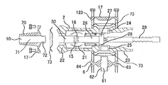
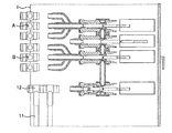
실시예 1에 대하여 도 1 내지 도 7을 이용하여 설명한다. 또한, 본 실시예에서는, 복모선 타입의 스위치 기어(1)에 대하여 설명한다. 여기서 도 1은, 도 11에 기재한 단선 결선도에 있어서의 수전반 혹은 피더반에 상당한다. 스위치 기어는 하우징 내에 하기에 서술하는 각종 기기를 수납한다.The first embodiment will be described with reference to Figs. 1 to 7. Fig. In the present embodiment, the switchgear type of the multi-bit line type will be described. Here, Fig. 1 corresponds to the water front or feeder half in the single-line wiring diagram shown in Fig. The switchgear houses the various devices described below in the housing.
개폐기는, 복수의 개폐기 유닛을 조립하여 구성된다. 구체적으로는, 최하부에 배치되는 1개의 차단기 유닛(2)과, 차단기 유닛(3)의 높이 방향 상측에 나란히 배치되는 3개의 단로기 유닛(3, 4, 5)으로 구성되고, 각 유닛 사이는 2종류의 접속 부재(6, 7)로 연결되어 있다. 접속 부재(6)는, 단로기 유닛 사이를 접속하는 부재이다. 정중앙의 단로기 유닛(4)을 하기에 서술하는 바와 같이 접지 개폐기로 하고 있고, 단로기 유닛끼리의 간격을 좁히고 있으므로, 접속 부재(6)는 접속 부재(7)와 비교하여 짧게 형성되어 있다. 접속 부재(6, 7)는, 도체의 주위를 수지 등의 절연물로 덮음으로써 형성된다. 단로기 유닛(4)에는 부싱(10)이 접속되고, 동 부싱(10)은 접지 E(어스)되어 있다. 즉, 단로기 유닛(4)은 접지 개폐기로서 기능한다. 또한, 통상의 운용 상태에서는 상기한 바와 같이, 부싱(10)은 접지된 상태로 되어 있지만, 필요에 따라서 접지와 분리하여, 케이블(11)의 내전압 시험용 단자로서 사용하는 것도 가능하다.The switch is constituted by assembling a plurality of switch units. Concretely, the circuit breaker is composed of one
단로기 유닛(3)에는 제1 모선(A)이, 단로기 유닛(5)에는 제2 모선(B)이 각각 접속된다. 각 유닛과 모선의 접속에는, 2종류의 접속 부재(13, 14)를 사용한다. 접속 부재(13)는 직선 형상을 이루고, 접속 부재(14)는 만곡시켜 상(相)마다의 공간적인 간섭을 피하고 있다. 본 실시예에서는, 정중앙의 높이를 갖는 V상의 모선에 대하여, 나머지 U상, W상의 모선은 V상의 모선에 대하여 상하로 대칭으로 되는 위치에 배치되어 있다. 이것은, 단로기 유닛(3, 5)의 V상(3상을 U상, V상, W상이라 칭함)과 모선(A, B)의 V상의 높이 방향의 위치를 맞추고, U상, W상을 V상에 대하여 대칭의 위치에 배치하면, 만곡하는 접속 부재(14)는 1종류만으로 할 수 있기 때문이다.The first bus bar A is connected to the
차단기 유닛(2)의 고정측에는 부하에 전력을 공급하기 위한 케이블(11)이 케이블 헤드(12)를 통해 접속된다. 본 실시예에서는 전류 용량을 확보하기 위해 2개의 케이블을 접속한 예를 나타내고 있다. 물론 케이블의 개수는 2개로 한정되는 것은 아니다. 설치 환경에 따라서 개수를 변화시키는 것이 가능하다.On the fixed side of the
상술한 바와 같이, 차단기 유닛(2), 단로기 유닛(3, 4, 5), 케이블(11) 및 모선(A, B)을 서로 연결함으로써, 수전반 및 피더반을 구성할 수 있다.As described above, by connecting the
차단기 유닛(2) 및 단로기 유닛(3, 4, 5)은, 그들의 가동부가 스위치 기어(1)에 대해 수평 방향으로 구동하도록 배치하고, 각 유닛을 스위치 기어(1)의 높이 방향으로 나란히 배치하고 있다. 가동부를 구동하기 위한 조작 기구, 즉, 차단기 유닛용 조작 기구(8), 단로기 유닛용 조작 기구(9)는 스위치 기어(1)의 정면측에 배치시키고 있어, 조작원이 액세스하기 쉬운 배치에 이르도록 하고 있다. 또한, 정면측에는 개폐 가능한 도어(100)를 장착하고 있다.The
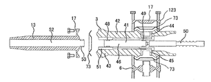
다음으로, 차단기 유닛(2)에 대하여 도 3을 이용하여 설명한다. 차단기 유닛(2)과 접속 부재(7)나 케이블 헤드(12)와의 접속 방법은, 개폐기 유닛 사이의 접속 부재(6)의 각 개폐기 유닛에의 접속 방법이나, 각 개폐기 유닛과 모선과의 사이의 접속 부재(13)의 각 개폐기 유닛에의 접속 방법에 공통되므로, 이들에 대해서도 도 3을 이용하여 아울러 설명한다. 또한, 부호 123은, 차단기 유닛(2)이나 단로기 유닛(3, 4, 5)의 개폐기 유닛이 연결된 유닛의 단부에 위치하였을 때 사용하는 절연용의 덮개이다. 도 3은 차단기 유닛을 도시하는 도면이지만, 도 1에 있어서의 차단기 유닛(2)의 위치에 배치되는 모습을 나타내고 있지는 않고, 예를 들어 도 1에 있어서의 단로기 유닛(3)과 같이, 상기 유닛의 상측에는 접속 부재가 접속되지 않는 위치에 배치되는 경우를 나타내고 있다.Next, the
차단기 유닛(2)은, 내부가 진공으로 밀폐되어 있는 진공 밸브 내에 고정 전극(15)과, 고정 전극(15)에 대향함과 함께, 수평 방향으로 구동하여 고정 전극(15)에 접촉 또는 개극되는 가동 전극(16)을 갖고, 고정 전극(15)은 배면측에서 수평 방향으로 연장되는 고정 도체(30)와 접속되고, 가동 전극(16)은 정면측에서 수평 방향으로 연장되는 가동 도체(26)와 접속된다. 진공 밸브(21)의 고정 도체(30)는, 케이블 헤드(12)에 접속하기 위한 부싱(10)과 연결된다. 부싱(10)은, 애관(碍管)(70)과 중심 도체(71)로 구성되고, 중심 도체(71)에는, 고정 도체(30)와 통전하기 위한 밴드 접점(72)을 설치하고 있다. 또한, 후술하지만, 차단기 유닛을 본 실시예에서는 케이블과의 접속 부위에만 설치하고 있으므로, 차단기 유닛은 부싱(10)과 접속되지만, 접속 부재(13)와 접속시켜도 된다. 본 실시예의 구조에 있어서는, 부싱(10)에의 접속과 접속 부재(13)에의 접속을 설치 환경에 따라서 용이하게 변경시키기 위해, 호환성을 갖게 하고 있다. 즉, 접속부의 구조를 차단기 유닛(2)과 단로기 유닛(3, 4, 5)에서 공통으로 하고 있다.The
가동 도체(26)는, 진공 용기와의 사이에 벨로우즈를 갖고 있고, 벨로우즈에 의해, 가동 도체(26)의 가동을 허용하면서, 진공 용기 내의 기밀성이 유지되도록 하고 있다. 가동 도체(26)는 진공 용기 내로부터 진공 용기 밖에 걸쳐 연신되어 있고, 진공 용기 외부에서 부재(27)를 고정하고 있다. 그리고, 부재(27)의 외주에는, 도체(24, 25)에 대한 집전용 밴드 접점(28)을 구비하고 있다. 또한, 가동 도체(26)의 정면측 단부에는 절연 로드(29)가 연결되어 있고, 상기 절연 로드(29) 자체는 차단기 유닛용 조작 기구(8)에 의해 수평 방향으로 구동된다. 절연 로드(29)의 수평 방향의 동작에 수반하여, 가동 도체(26) 및 가동 전극(16)도 수평 방향으로 구동된다.The
차단기 유닛(2)에는, 진공 밸브(21)의 주위에 에폭시 등의 절연용 수지(22)를 몰드하고, 그 외표면에는 도전 도료(23)를 실시하고 있다. 도전 도료(23)는 접지 전위로 하고 있어, 이 부분에 대한 사람의 접촉 안전성을 확보하고 있다.The
차단기 유닛(2)의 측면(높이 방향)에는 상하로 2개의 도체(24, 25)를 설치하고 있다. 도체[도 3에서는 도체(25)]를 접속 부재(6)와 결합하여, 유닛 사이의 통전을 확보한다. 접속 부재(6)는 중심 도체(61)와 중심 도체(61)를 지지하는 절연물성의 플랜지(63)를 포함하고, 중심 도체(61)에는 접촉하는 도체[도 3에서는 도체(25)]와 미끄럼 이동 통전하기 위한 밴드 접점(62)을 구비한다. 또한, 도 3에서는, 도체(25)를 접속 부재(6)와 결합시키고 있지만, 설치 환경에 따라서 도체(24)를 접속 부재(6)와 결합시키도록 하거나, 절연 덮개(123) 대신에, 도체(24)와 도체(25)의 양쪽을 각각의 접속 부재(6) 또는 접속 부재(6, 7)에 걸림 결합시키도록 하는 것은 가능하다. 도 1에 도시하는 구조에서는, 실제로, 도체(24)에는 접속 부재(7)를 접속하고 있고, 도체(25)측에는 접속 부재를 접속하지 않고, 절연 덮개(123)를 설치하고 있다. 또한, 절연물성의 플랜지(63)의 외표면에도 접지하기 위한 도전 도료(64)를 실시하고 있어, 접촉 안전성을 확보하고 있다.Two
부싱(10), 접속 부재(6, 7), 접속 부재(13, 14)나 절연 덮개(123)를 개폐기 유닛[차단기 유닛(2) 또는 단로기 유닛]에 고정하는 경우, 개폐기 유닛과, 부싱(10), 접속 부재(6, 7)나 절연 덮개(123)와의 사이에, 고무 링(73)을 끼워 지지시킨다. 이 고무 링(73)은 중심의 고전압부와 주위의 접지 사이의 절연을 확보하기 위한 것으로, 실리콘 고무나 EP 고무 등으로 제작된 것이다. 접속 부재(6)는, 상하에 개폐기 유닛이 접속되는 것을 상정하고 있고, 수평축에 대하여 상하로 선대칭인 형상으로 되어 있다[이것은, 개폐기 유닛이 상하에 동일한 형상의 접속 부위를 갖는 것을 전제로 하고 있다. 개폐기 유닛이 상하에서 접속 부위의 형상을 바꾸어 형성되어 있는 경우, 접속 부재(6)도 개폐기 유닛과 끼워 맞출 수 있는 형상으로 치환할 필요가 있는 것은 물론이다.]. 부싱(10), 접속 부재(7), 접속 부재(13, 14)나 절연 덮개(123)에 관해서는, 개폐기 유닛과 접속되는 측의 면과는 반대측의 면은 평탄부(17)로 되어 있고, 상기 평탄부(17)로부터 고무 링(73)을 통해 개폐기 유닛에 볼트 등의 체결 부재로 고정한다.When the
본 실시예에서는, 차단기 유닛(2)에 접속한 부싱(10)은, 스위치 기어(1)의 배면측에서 케이블 헤드(12)에 접속되고, 케이블(11)과 접속된다.The
다음으로, 단로기 유닛(3)의 구조에 대해, 도 4를 이용하여 설명한다. 도 4에 있어서의 단로기 유닛은, 도 1 중에서, 단로기 유닛(3)과 같이, 상기 유닛의 상측에는 접속 부재가 접속되지 않는 위치에 배치되는 경우를 나타내고 있다. 다른 단로기 유닛(4, 5)에 대해서는, 절연 덮개(123) 대신에 접속 부재(6)나 접속 부재(7)가 접속된다. 또한 하측에 대해서도 접속 부재(6) 대신에 접속 부재(7)가 접속되는 경우도 있다. 예를 들어, 단로기 유닛(5)에서는, 하측에 대하여 접속 부재(6) 대신에 접속 부재(7)가 접속된다.Next, the structure of the
단로기 유닛(3, 4, 5)은, 전류 차단 성능을 가질 필요가 없고, 서지 내전압을 개극시에 가지면 되므로, 진공 밸브가 아닌, 기중(氣中) 개폐기(41)로 되어 있고, 고정 전극을 겸용하는 고정 도체(51)와, 수평 방향으로 신장되는 가동 도체(46)를 갖는다. 가동 도체(46)의 주위에는, 고정 도체(51)에 대향함과 함께, 수평 방향으로 구동하여 고정 도체(51)에 접촉 또는 개극되는 가동 전극에 상당하는 밴드 접점(48)을 갖는다. 기중 개폐기(41)의 고정 도체(51)는, 접속 부재(13)의 중심에 설치되는 중심 도체(52)와 연결된다. 중심 도체(52)에는, 고정 도체(51)와 통전하기 위한 밴드 접점(53)을 설치하고 있다. 또한, 본 실시예에서는 대표적으로 수평 방향에서 배면측으로 연신되는 접속 부재(13)를 예로 들어 설명하고 있지만, 접속 부재(13) 대신에 접속 부재(14)를 접속할 수도 있다. 실제로, U, V, W의 3상의 모선 중, 정중앙의 높이를 갖는 모선(본 실시예에서는 V상)에 대하여, 나머지 2상(U상, W상)은 정중앙의 높이를 갖는 V상의 모선으로부터 대칭으로 되는 위치에 상하로 배치되어 있고, 스트레이트로 수평 방향으로 연신되는 것이 아닌, 굴곡할 필요가 있으므로, U상, W상에 대해서는 접속 부재(14)를 접속하고 있다. 또한, 접지 개폐기로서 사용하는 경우에는, 접속 부재(13) 대신에 부싱(10)을 접속한다. 본 실시예의 구조에 있어서는, 부싱(10)에의 접속과 접속 부재(13, 14)에의 접속을 설치 환경에 따라서 용이하게 변경시키기 위해, 호환성을 갖게 하고 있다. 즉, 접속부의 구조를 차단기 유닛(2)과 단로기 유닛(3, 4, 5)의 각 개폐기 유닛 사이에서 공통인 구조로 하고 있다.The
단로기 유닛에 대해서도 차단기 유닛(2)과 마찬가지로, 기중 개폐기(41)의 주위에 에폭시 등의 절연용 수지(42)를 설치하고, 그 외표면에는 접지하기 위한 도전 도료(43)를 실시하고 있다. 단로기 유닛의 측면에는 2개의 도체(44, 45)를 설치하고 있다. 이 도체(44, 45)를 접속 부재(6)나 접속 부재(7)와 결합하여, 유닛 사이의 통전을 확보한다[도 4에 있어서는 도체(45)를 접속 부재(6)와 접속하고 있다.]. 또한, 단부에 위치하는 단로기 유닛에 대해서는, 단부측(상측 또는 하측. 도 4에 있어서는 상측이 단부측)에는 접속 부재(6, 7) 대신에 절연 덮개(123)를 설치한다.As in the case of the
수평 방향으로 연신되는 가동 도체(46)는 정면측에서, 가동 도체(46)의 외주에 도체(44, 45)에 대한 집전용 밴드 접점(49)을 구비하고 있다. 또한, 가동 도체(46)의 정면측 단부에는 절연 로드(50)가 연결되어 있고, 절연 로드(50) 자체는 단로기 유닛용 조작 기구(9)에 의해 수평 방향으로 구동된다. 절연 로드(50)의 수평 방향의 동작에 수반하여, 가동 도체(46) 및 밴드 접점(48)도 수평 방향으로 구동된다.The
부싱(10), 접속 부재(6, 7), 접속 부재(13, 14)나 절연 덮개(123)를 단로기 유닛에 고정하는 경우에도, 단로기 유닛과, 부싱(10), 접속 부재(6, 7)나 절연 덮개(123)와의 사이에, 고무 링(73)을 끼워 지지시킨다. 이 고무 링(73)은 중심의 고전압부와 주위의 접지 사이의 절연을 확보하기 위한 것으로, 실리콘 고무나 EP 고무 등으로 제작된 것이다. 접속 부재(6)는, 상하에 개폐기 유닛이 접속되는 것을 상정하고 있고, 수평축에 대하여 상하로 선대칭인 형상으로 되어 있다[이것은, 개폐기 유닛이 상하에 동일한 형상의 접속 부위를 갖는 것을 전제로 하고 있다. 개폐기 유닛이 상하에서 접속 부위의 형상을 바꾸어 형성되어 있는 경우, 접속 부재(6)도 개폐기 유닛과 끼워 맞출 수 있는 형상으로 치환할 필요가 있는 것은 물론이다.]. 부싱(10), 접속 부재(7), 접속 부재(13, 14)나 절연 덮개(123)에 관해서는, 개폐기 유닛과 접속되는 측의 면과는 반대측의 면은 평탄부(17)로 되어 있고, 상기 평탄부(17)로부터 고무 링(73)을 통해 개폐기 유닛에 볼트 등의 체결 부재로 고정한다. 이 접속부에 관해서는, 기본적으로 상기 차단기 유닛과 마찬가지이다. 마찬가지이기 때문에, 호환성을 갖고, 용이하게 치환하여 적용하는 것이 가능하다.Even when the
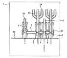
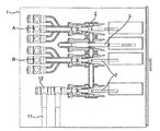
본 실시예에 있어서, 접속 부재(13, 14)는 스위치 기어(1)의 배면측에 있어서 이중 모선(A, B)과 접속된다. 도 2는, 모선 및 케이블의 접속 상태를 나타내기 위해, 본 실시예에 따른 스위치 기어(1)를 배면측으로부터 본 도면이다. 모선(A, B) 각각에 접속되는 모선 접속 부위는, 높이 방향, 수평 방향에 있어서 소정의 간격으로 어긋나게 배치된다. 또한, 배면도인 도 2에 모선 및 케이블의 접속부가 나타나 있는 것으로부터 명백한 바와 같이, 본 실시예에 따른 스위치 기어(1)에 의하면, 현지에서 접속하는 모선 및 케이블의 접속부가, 모두 작업자에게 있어서 액세스 용이한 배면측에 위치하고 있다.In the present embodiment, the connecting
여기서, 본 실시예에 따른 스위치 기어(1)의 조립 방법에 대하여 도 5, 도 6을 이용하여 설명한다.Here, a method of assembling the switchgear 1 according to the present embodiment will be described with reference to Figs. 5 and 6. Fig.
도 5는 개폐기 부분의 조립 방법을 나타내고, 스위치 기어(1)는 가로로 눕힌 상태로 되어 있고, 각 개폐기 유닛의 가동 전극의 구동 방향은, 높이 방향으로 된다. 본 실시예에서는 차단기 유닛(2)과 3개의 단로기 유닛(3, 4, 5)을 사용하므로, 이 개폐기 유닛을, 접속 부재(6, 7)를 사용하여 연결하고, 베이스(60)의 상부에 고정한다. 모선(A, B)과의 접속 부재(13, 14), 케이블(11)과 접속하기 위한 부싱(10)을 각 유닛에 고정한다.Fig. 5 shows a method of assembling the switchgear portion. The switchgear 1 is laid down in a lateral direction, and the drive direction of the movable electrode of each switchgear unit is the height direction. Since the
차단기 유닛(2) 및 단로기 유닛(3, 4, 5)이 조립된 후, 도 6에 도시하는 바와 같이, 스위치 기어(1)를 정규의 상태로 복귀시키고(가동 전극의 구동 방향이 수평 방향으로 되도록 세움), 그 후, 차단기 유닛용 조작 기구(8)와 단로기 유닛용 조작 기구(9)를 설치하여, 스위치 기어(1)의 주요 부분이 완성된다.6, after the
모선(A, B) 및 케이블(11)의 고정은 현지에서 행할 필요가 있다. 현지에 있어서의 모선(A, B) 및 케이블(11)의 고정 방법을 도 7에 도시한다. 본 실시예에 있어서의 스위치 기어(1)에 의하면, 모선이나 케이블과의 접속부가 모두 스위치 기어(1)의 배면측에 설치되어 있고, 어느 것에 대해서도 스위치 기어(1)의 배면으로부터의 액세스만으로 용이하게 설치할 수 있다.It is necessary to fix the bus bars A and B and the
스위치 기어(1)를 구성하는 차단기 유닛(2) 및 단로기 유닛(3, 4, 5)의 가동부를 수평 방향으로 구동하도록 배치하고, 또한 각 유닛을 스위치 기어의 높이 방향으로 배열한 구성으로 하고, 또한 주 회로 부분을 조립할 때, 스위치 기어(1)를 가로로 눕히는 방법을 채용하고 있다. 이 구조 및 방법에 의해, 각 부재를 중력에 역행하는 일 없이 장착하는 것이 가능해지고, 조립 작업성이 향상되어, 공정수 저감, 즉 경제성이 유리해진다.The movable parts of the
본 실시예에 의하면, 수평 방향으로 구동하는 가동 전극을 갖는 복수의 개폐기 유닛을 높이 방향으로(공간적으로 비틀리는 위치가 아닌, 평행으로 되는 식으로) 나란히 배치하고, 조작 기구를 스위치 기어 하우징의 일방측에 집약하여 배치하고, 모선이나 케이블의 접속부를 하우징의 타방측에 집약하여 배치하였으므로, 하우징의 배면측으로부터 작업자가 용이하게 액세스할 수 있는 위치에 현지에서 작업하기 위한 접속부가 위치하게 되어, 작업성이 향상된다.According to the present embodiment, a plurality of switchgear units each having a movable electrode that is driven in the horizontal direction are arranged side by side in a height direction (not parallel to the spatially twisted position) The connecting portion for working locally is located at a position where the worker can easily access from the rear side of the housing, Thereby improving the stability.
또한, 본 실시예에서는, 각종 부싱(10), 접속 부재(6, 7), 접속 부재(13, 14)나 절연 덮개(123) 등에 대하여 차단기 유닛과 단로기 유닛은 접속부의 호환성을 갖도록 하고 있고, 설치 환경에 따라서 조합을 용이하게 바꿀 수 있게 된다. 즉, 모선 및 서로의 유닛 사이의 취합이 공통화되어, 다양한 회로 구성의 실현이 용이해진다. 구체적으로는, 차단기 유닛 및 단로기 유닛에 있어서의 접속 부재와의 접속부는 공통인 구조를 갖고 있다.In the present embodiment, the breaker unit and disconnecting unit are made compatible with each other with respect to the
또한, 본 실시예에 있어서는, 정중앙의 높이를 갖는 V상의 모선에 대하여, 나머지 2상은 정중앙의 높이를 갖는 V상의 모선으로부터 대칭으로 되는 위치에 상하로 배치하고 있어, 정중앙의 높이에 배치되는 V상의 모선에 대하여 상하로 배치되는 U상, W상의 모선 접속부로 되는 접속 부재(14)의 구조를 1종류로 하여 공통화하고 있다. 따라서, 부재의 범용성을 더욱 향상시킬 수 있다.Further, in this embodiment, the remaining two phases of the V-phase busbars having the height of the center are arranged vertically at positions symmetrical with respect to the V-phase busbars having the center height, and the V phase The structure of the connecting
또한, 모선(A, B)에 대해서도, 스위치 기어(1)의 배면측에 높이 방향으로 나란히 배치하였으므로, 현지에서 실시하는 모선 장착 작업도 용이하게 실시할 수 있다.Since the busbars A and B are also arranged in the height direction on the back side of the switchgear 1, it is possible to easily carry out the busbing work performed locally.
또한, 본 실시예에서는, 복모선 타입을 예로 들어 설명하였지만, 단모선 타입에 대해서도, 모선(A), 차단기 유닛(2) 및 단로기 유닛(3, 4)의 조합으로 구성할 수 있다.In this embodiment, the bus line type is taken as an example. However, the bus line type can also be configured by a combination of the bus line A, the
실시예 2Example 2
실시예 2에 대하여 도 8을 이용하여 설명한다. 또한, 실시예 1과 중복되는 구성(및 그 구성을 채용함으로써 얻어지는 효과)에 대해서, 여기서의 설명은 생략한다.The second embodiment will be described with reference to FIG. The description of the configuration that overlaps with Embodiment 1 (and the effect obtained by employing the configuration) is omitted here.
본 실시예는, 복모선 타입의 스위치 기어에 있어서, 단로기에 루프 전류 차단 책무가 요구된 경우 등, 단로기 유닛에 전류 차단 성능을 갖게 하는 경우에 대하여 설명하는 것이다. 도 8에 그 구성을 도시한다. 도 4에 도시하는 기중 개폐기의 단로기 유닛(3)에는 차단 능력이 없으므로, 제1 모선(A)과 제2 모선(B)에 각각 접속되는 단로기에, 실시예 1에서 설명한 도 3에 도시하는 차단기 유닛(2)을 적용한다. 단, 제1 모선(A)과 제2 모선(B)에 각각 접속되는 차단기 유닛(2)에도, 단로기 규격으로 규정되는 극간 내전압을 확보시켜, 서지 내전압을 개극시에 갖도록 한다.The present embodiment explains a case where a disconnecting unit is provided with a current interruption capability, such as when a disconnecting unit is required to observe a loop current in a switchgear of a multi-bit line type. 8 shows the configuration thereof. The
실시예 1에서 설명한 바와 같이, 차단기 유닛(2)과 단로기 유닛(3)은 각종 접속 부재와의 취합을 공통의 구조로 하고, 호환성을 갖게 하고 있으므로, 제1 모선(A)과 제2 모선(B)에 각각 접속되는 단로기는, (단로기 규격에 대응시킬 필요는 있지만) 기본적으로 단로기 유닛(3)을 차단기 유닛(2)으로 치환하는 것으로 충분하다. 이와 같이, 사용자의 용도에 따라서, 실시예 1에서 도 1의 회로 구성으로 하거나, 혹은 본 실시예에서 도 8의 회로 구성으로 하는 것은, 차단기 유닛(2)이나 단로기 유닛(3)을 선택하면 되므로 용이하다.As described in the first embodiment, the
실시예 3Example 3
실시예 3에 대하여 도 9를 이용하여 설명한다. 본 실시예에 있어서도 상기 각 실시예와 중복되는 개소에 대해서는, 그 설명을 생략한다.The third embodiment will be described with reference to FIG. In the present embodiment, description of the portions that are the same as those of the above-described embodiments will be omitted.
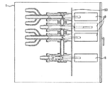
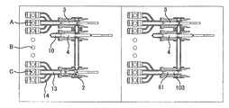
본 실시예는, 복모선 타입의 스위치 기어에 있어서, 모선 구분반을 실현한 예이다. 모선 구분반은, 도 9에 기재된 바와 같이 좌우의 스위치 기어를 열반하여 구성하고 있다. 모선 구분반의 회로 구성에 대해서도 도 11에 도시되어 있다.The present embodiment is an example of realizing a bus bar section in a multi-comb line type switchgear. As shown in Fig. 9, the bus bar section is formed by laminating left and right switch gears. The circuit configuration of the bus line segment is also shown in Fig.
모선 구분반에서는, 수전반이나 피더반에서 설치하고 있었던 케이블(11) 대신에 좌우의 스위치 기어를 연결하기 위한 연락 모선(C)을 설치하고 있다. 연락 모선(C)에 의해 접속하므로, 차단기 유닛은 2개의 스위치 기어 각각에서 구비할 필요가 없고, 한쪽의 스위치 기어에서만 구비하고 있으면 된다. 도 9에 기재된 구조에 있어서는, 좌측에 배치되는 스위치 기어만이 차단기 유닛(2)을 구비하고 있다. 차단기 유닛(2)에는, 연락 모선(C)에 접속할 수 있도록, 부싱(10) 대신에 접속 부재(13, 14)를 접속하고 있다[접속 부재(13)는 높이 방향으로 정중앙에 위치하는 상, 접속 부재(14)는 높이 방향으로 정중앙에 위치하는 상에 대하여 상하로 대칭으로 배치되는 상으로 설치하는 것이 바람직하다. 이 점도 상기 실시예와 마찬가지이다.]. 차단기 유닛을 구비하고 있지 않은 스위치 기어에 대해서는, 차단기 유닛(2) 대신에 단로기 유닛(103)이 설치되고, 상기 단로기 유닛(103)은 배면측에서 연락 모선(C)과 접속된다.In the bus bar section, a contact bus C for connecting left and right switch gears is provided instead of the
또한 모선 구분반에 적용되는 스위치 기어 내에서는, [연락 모선(C)은 제외하고] 상기 모선(A, B)에 의한 이중 모선으로는 되어 있지 않고, 단로기 유닛을 1개 적게 한 구성으로 충분하다.Also, in the switchgear applied to the busbar section, it is sufficient not to form a double bus line by the busbars A and B (except for the contact bus line C) but to reduce the number of the disconnector units by one .
또한, 본 실시예와 같이 스위치 기어를 구성하는 데 있어서도, 접속 부재(13, 14)나 부싱(10)에 대하여, 차단기 유닛(2)과의 접속 구조 및 단로기 유닛(3)과의 접속 구조를 공통으로 하였으므로, 모선(A, B)의 접속 구조를 구성하는 경우와 동일 부재로 연락 모선(C)과 차단기 유닛(2)과의 접속 구조를 구성할 수 있다. 또한, 상술한 바와 같이 우측의 스위치 기어에는 차단기 유닛(2)은 불필요하고, 연결을 위해 단로기 유닛(103)을 활용하고 있지만, 가동 도체(81)는 동작시킬 필요는 없고, 내부에 고정해 둔다. 즉, 단로기 유닛(103)에 대해서는 조작 기구가 불필요해진다.The connection structure with the
즉, 상기 각 실시예에서 설명한 스위치 기어를 사용하여 용이하게 모선 구분반을 조립하는 것이 가능해진다.That is, it becomes possible to easily assemble the bus bar section using the switchgears described in the above embodiments.
실시예 4Example 4
실시예 4에 대하여 도 10을 이용하여 설명한다. 본 실시예에 있어서도 상기 각 실시예와 중복되는 개소에 대해서는, 그 설명을 생략한다.The fourth embodiment will be described with reference to FIG. In the present embodiment, description of the portions that are the same as those of the above-described embodiments will be omitted.
본 실시예는, 복모선 타입의 스위치 기어에 있어서, 모선 연락반을 실현한 예이다. 모선 연락반은, 실시예 3에서 설명한 모선 구분반과 마찬가지로, 도 10에 기재된 바와 같이 좌우의 스위치 기어를 열반하여 구성하고 있다. 모선 연락반의 회로 구성에 대해서도 도 11에 도시되어 있다. 모선 연락반에 있어서 실시예 3에서 설명한 모선 구분반과 다른 점은, 이중 모선(A, B) 중, 좌우의 스위치 기어에서 접속하는 모선이 다른(한쪽이 모선 A이면, 다른 쪽은 모선 B) 점이다.The present embodiment is an example of realizing a bus communication section in a switchgear of a multiple bus type. The bus line communication panel is constituted by laminating left and right switch gears as shown in Fig. 10, in the same manner as the bus line partitioning unit explained in the third embodiment. The circuit configuration of the bus line communication unit is also shown in Fig. The bus line communication unit is different from the bus line division unit described in the third embodiment in that the bus lines connecting the right and left switchgears out of the double bus lines A and B are different (one bus line A and the other bus line B) to be.
본 실시예에서도, 접속 부재(13, 14)나 부싱(10)에 대해, 차단기 유닛(2)과의 접속 구조 및 단로기 유닛(3)과의 접속 구조를 공통으로 하였으므로, 모선(A, B)의 접속 구조를 구성하는 경우와 동일 부재로 연락 모선 C와 차단기 유닛(2)과의 접속 구조를 구성할 수 있다.Since the connection structure with the
즉, 상기 각 실시예에서 설명한 스위치 기어를 사용하여 용이하게 모선 연락반을 조립하는 것이 가능해진다.That is, it becomes possible to easily assemble the bus connector using the switchgears described in the above embodiments.
또한, 상기 각 실시예에서 설명한 조합은 일례이며, 이것 이외에도 설치 환경에 따라서 다양한 조합을 실현할 수 있는 것도 본 발명의 우수한 점이다.The combination described in each of the above embodiments is merely an example, and it is also an advantage of the present invention that various combinations can be realized according to the installation environment.
1 : 스위치 기어
2 : 차단기 유닛
3, 4, 5, 103 : 단로기 유닛
6, 13, 14 : 접속 부재
8 : 차단기 유닛용 조작 기구
9 : 단로기 유닛용 조작 기구
10 : 부싱
11 : 케이블
12 : 케이블 헤드
15 : 고정 전극
16 : 가동 전극
17 : 평탄부
21 : 진공 밸브
22, 42 : 수지
23, 43, 64 : 도전 도료
24, 25, 44, 45 : 도체
26, 46, 81 : 가동 도체
27 : 부재
28, 48, 49, 53, 62, 72 : 밴드 접점
29, 50 : 절연 로드
30, 51 : 고정 도체
41 : 기중 개폐기
52, 61 : 중심 도체
63 : 플랜지
73 : 고무 링
123 : 절연 덮개
A, B : 모선
C : 연락 모선1: Switch gear
2: Breaker unit
3, 4, 5, 103: disconnecting unit
6, 13, 14: connecting member
8: Operating mechanism for breaker unit
9: Operating mechanism for disconnecting unit
10: Bushing
11: Cable
12: Cable head
15: Fixed electrode
16: movable electrode
17:
21: Vacuum valve
22, 42: Resin
23, 43, 64: conductive paint
24, 25, 44, 45: conductors
26, 46, 81: movable conductors
27: absence
28, 48, 49, 53, 62, 72: band contact
29, 50: Insulation rod
30, 51: Fixed conductor
41: lifter switch
52, 61: center conductor
63: Flange
73: Rubber ring
123: Insulation cover
A, B: Mothership
C: Contact mother ship
Claims (11)
상기 복수의 개폐기 유닛에 있어서의 상기 가동 전극을 조작하는 복수의 조작 기구와,
상기 개폐기 유닛에 설치되고, 모선과 접속되는 모선 접속부와,
상기 모선 접속부, 상기 복수의 개폐기 유닛, 및 상기 복수의 조작 기구 모두를 내부에 갖는 하우징
을 구비하고,
복수의 상기 개폐기 유닛은 높이 방향으로 배치되고,
복수의 상기 조작 기구를, 상기 하우징의 정면측 또는 배면측에 배치하고,
복수의 상기 모선 접속부를, 상기 하우징의 타방측에 배치한 것을 특징으로 하는 스위치 기어.A plurality of switchgear units opposed to the fixed electrode and having a movable electrode which is driven in the horizontal direction to contact or open the fixed electrode;
A plurality of operating mechanisms for operating the movable electrodes of the plurality of switchgear units,
A bus connecting portion provided on the switch unit and connected to the bus bar,
A housing having therein the bus-line connecting portion, the plurality of switchgear units, and the plurality of operating mechanisms,
And,
A plurality of said switchgear units are arranged in a height direction,
A plurality of the operating mechanisms are disposed on the front side or back side of the housing,
And the plurality of bus-line connecting portions are disposed on the other side of the housing.
상기 개폐기 유닛끼리는 접속 부재에 의해 접속되고, 각 상기 개폐기 유닛에 있어서의 접속 부재와의 접속부는 호환성을 갖도록 형성되어 있는 것을 특징으로 하는 스위치 기어.The method according to claim 1,
Wherein the switchgear units are connected to each other by a connecting member, and the connection portions to the connecting members of each of the switchgear units are formed to have compatibility.
상기 개폐기 유닛은, 전류 차단 성능을 갖는 차단기 유닛과, 서지 내전압을 개극시에 갖는 단로기 유닛을 포함하고,
상기 차단기 유닛 및 상기 단로기 유닛에 있어서의 접속 부재와의 접속부는 호환성을 갖도록 공통의 구조를 갖는 것을 특징으로 하는 스위치 기어.3. The method of claim 2,
Wherein the switch unit includes a breaker unit having a current breaking capability and a disconnector unit having a surge withstand voltage at the time of opening,
And the connecting portions of the breaker unit and the disconnecting unit in the disconnecting unit have a common structure so as to have compatibility.
3상의 각 상기 개폐기 유닛은, 각 상 서로 동일한 높이로 배치되고,
3상의 모선은, 각 상에서 다른 높이로 배치되고,
상기 3상의 모선 중, 정중앙의 높이를 갖는 모선에 대하여, 나머지 2상은 상기 정중앙의 높이를 갖는 모선으로부터 대략 대칭 위치에 상하로 배치되고,
개폐기 유닛과 모선을 접속하는 모선 접속부의 형상에 대해, 상기 정중앙의 높이로 배치되는 모선에 대하여 상하로 배치되는 상의 모선 접속부의 형상은 공통인 것을 특징으로 하는 스위치 기어.4. The method according to any one of claims 1 to 3,
Each of the three switchgear units is arranged at the same height as each of the phases,
The three-phase busbars are arranged at different heights in each phase,
The remaining two phases of the three phases of the busbars having a height of the center are arranged up and down at approximately symmetrical positions from the busbars having the height of the center,
Wherein a shape of a bus-line connecting portion connecting upper and lower portions with respect to a bus line arranged at the height of the center is common to the shape of the bus-line connecting portion connecting the switchgear unit and the bus-bar.
상기 개폐기 유닛은,
상기 조작 기구에 접속되어 수평 방향으로 동작하는 절연 로드와,
상기 절연 로드의 구동에 수반하여 수평 방향으로 동작하는 가동 도체와,
상기 절연 로드 및 상기 가동 도체에 대하여 상하로 배치되는 도체와,
상기 도체와 미끄럼 이동 통전하고, 상기 가동 도체와의 사이를 전기적으로 접속하는 밴드 접점을 갖고,
상기 개폐기 유닛과, 상기 개폐기 유닛에 접속되는 도체와의 접속부는 고무 링을 갖는 것을 특징으로 하는 스위치 기어.5. The method according to any one of claims 1 to 4,
The switch unit includes:
An insulating rod connected to the operating mechanism and operating in a horizontal direction,
A movable conductor which operates in a horizontal direction following the driving of the insulating rod;
A conductor disposed up and down with respect to the insulating rod and the movable conductor,
A band contact electrically connected to the conductor and electrically connected to the movable conductor,
Wherein the connecting portion of the switchgear unit and the conductor connected to the switchgear unit has a rubber ring.
상기 모선은 상마다 이중으로 설치되고,
전류 차단 성능을 갖는 차단기 유닛, 및 상기 차단기 유닛의 높이 방향으로 상측에 나란히 배치되는 3개의 단로기 유닛을 갖고,
상기 단로기 유닛은 서지 내전압을 개극시에 갖고,
3개의 상기 단로기 유닛 중, 하나는 상기 이중 모선 중 하나의 모선에 접속되고, 다른 하나는 상기 이중 모선 중 다른 모선에 접속되고, 나머지 하나는 접지측과의 통전 또는 단로를 전환 가능하게 형성되고,
상기 차단기 유닛은 케이블과 접속되는 것을 특징으로 하는 스위치 기어.6. The method according to any one of claims 1 to 5,
The busbars are installed in a duplex manner for each phase,
A breaker unit having a current interruption capability and three disconnector units disposed side by side in a height direction of the breaker unit,
The isolator unit has a surge withstand voltage at a minimum,
One of the three disconnecting unit units is connected to one bus line of the double bus lines, the other bus line is connected to another one of the bus lines of the double bus lines, and the other is connected to the ground side,
Wherein the breaker unit is connected to a cable.
상기 단로기 유닛 중, 상기 이중 모선에 접속되는 2개의 단로기 유닛은, 또한 전류 차단 성능을 갖는 것을 특징으로 하는 스위치 기어.The method according to claim 6,
Wherein two disconnecting unit units connected to the double bus line among the disconnecting unit units further have a current interruption capability.
하나의 스위치 기어는, 전류 차단 성능을 갖는 차단기 유닛, 및 그 차단기 유닛의 높이 방향으로 상측에 나란히 배치되는 2개의 단로기 유닛을 갖고,
상기 단로기 유닛은 서지 내전압을 개극시에 갖고,
2개의 상기 단로기 유닛 중, 하나는 상기 이중 모선 중 하나의 모선에 접속되고, 다른 하나는 접지측과의 통전 또는 단로를 전환 가능하게 형성되고,
상기 차단기 유닛은 연락 모선에 접속되어 있고,
다른 스위치 기어는, 높이 방향으로 나란히 배치되는 3개의 단로기 유닛을 갖고,
상기 단로기 유닛은 서지 내전압을 개극시에 갖고,
3개의 상기 단로기 유닛 중, 하나는 상기 이중 모선 중 상기 하나의 모선에 접속되고, 다른 하나는 접지측과의 통전 또는 단로를 전환 가능하게 형성되고, 나머지 하나는 상기 연락 모선에 접속되는 것을 특징으로 하는 스위치 기어.A switchgear comprising two switchgears according to any one of claims 1 to 5,
One switchgear includes a breaker unit having a current breaking capability and two breaker units disposed side by side in the height direction of the breaker unit,
The isolator unit has a surge withstand voltage at a minimum,
One of the two disconnecting unit units is connected to one bus line of the double busbars and the other of the two disconnecting unit units is configured to be able to switch the energization or disconnection to the ground side,
The breaker unit is connected to the contact bus,
The other switchgear has three disconnecting unit units arranged side by side in the height direction,
The isolator unit has a surge withstand voltage at a minimum,
One of the three disconnecting unit units is connected to one of the busbars of the double busbars and the other of the three busbreaker units is configured to be able to switch the energization or disconnection from the ground side and the other is connected to the connecting busbars Switchgear.
하나의 스위치 기어는, 전류 차단 성능을 갖는 차단기 유닛, 및 그 차단기 유닛의 높이 방향으로 상측에 나란히 배치되는 2개의 단로기 유닛을 갖고,
상기 단로기 유닛은 서지 내전압을 개극시에 갖고,
2개의 상기 단로기 유닛 중, 하나는 상기 이중 모선 중 하나의 모선에 접속되고, 다른 하나는 접지측과의 통전 또는 단로를 전환 가능하게 형성되고,
상기 차단기 유닛은 연락 모선에 접속되어 있고,
다른 스위치 기어는, 높이 방향으로 나란히 배치되는 3개의 단로기 유닛을 갖고,
상기 단로기 유닛은 서지 내전압을 개극시에 갖고,
3개의 상기 단로기 유닛 중, 하나는 상기 이중 모선 중 상기 하나의 모선이 아닌 모선에 접속되고, 다른 하나는 접지측과의 통전 또는 단로를 전환 가능하게 형성되고, 나머지 하나는 상기 연락 모선에 접속되는 것을 특징으로 하는 스위치 기어.A switchgear for driving two switchgears according to any one of claims 1 to 5,
One switchgear includes a breaker unit having a current breaking capability and two breaker units disposed side by side in the height direction of the breaker unit,
The isolator unit has a surge withstand voltage at a minimum,
One of the two disconnecting unit units is connected to one bus line of the double busbars and the other of the two disconnecting unit units is configured to be able to switch the energization or disconnection to the ground side,
The breaker unit is connected to the contact bus,
The other switchgear has three disconnecting unit units arranged side by side in the height direction,
The isolator unit has a surge withstand voltage at a minimum,
One of the three disconnecting unit units is connected to a bus line other than the one bus line of the double bus lines and the other bus line is configured to switch the energization or disconnection from the ground side and the other is connected to the contact bus line The switchgear comprising:
상기 각 차단기 유닛 및 단로기 유닛은, 각각의 상기 가동 전극이 전기적으로 접속되어 있고,
전류 차단 성능을 갖는 상기 유닛은 상기 고정 전극 및 상기 가동 전극이, 내부가 진공으로 밀폐되어 있는 진공 밸브를 수지 몰드함으로써 형성되고, 또한 상기 고정 전극은 케이블과 전기적으로 접속되어 있고,
상기 단로기 유닛은 기중 절연 개폐기를 수지 몰드함으로써 형성되어 있는 것을 특징으로 하는 스위치 기어.10. The method according to any one of claims 6 to 9,
Wherein each of the breaker unit and disconnecting unit is electrically connected to each of the movable electrodes,
Wherein the fixed electrode and the movable electrode are formed by resin molding a vacuum valve whose interior is sealed by a vacuum, and the fixed electrode is electrically connected to the cable,
Wherein the disconnecting unit is formed by resin-molding an air insulated switch.
상기 복수의 개폐기 유닛에 있어서의 상기 가동 전극을 조작하는 복수의 조작 기구를 갖는 스위치 기어의 조립 방법으로서,
상기 가동 전극의 구동 방향이 높이 방향으로 되도록 하여 베이스에 대해 상기 개폐기 유닛을 고정하는 스텝과,
상기 개폐기 유닛의 고정 후에, 상기 가동 전극의 구동 방향이 수평 방향으로 되도록 세우는 스텝과,
상기 스텝 후에, 상기 복수의 개폐기 유닛에 조작 기구를 접속하는 스텝
을 갖는 것을 특징으로 하는 스위치 기어의 조립 방법.A plurality of switchgear units opposed to the fixed electrode and having a movable electrode which is driven in the horizontal direction to contact or open the fixed electrode;
And a plurality of operating mechanisms for operating the movable electrode in the plurality of switchgear units,
A step of fixing the switchgear unit to the base such that a driving direction of the movable electrode is a height direction;
A step of setting the driving direction of the movable electrode so as to be horizontal after fixing the switch unit,
After the step, connecting the operating mechanism to the plurality of switchgear units
And a step of connecting the switchgear and the switchgear.
Applications Claiming Priority (3)
| Application Number | Priority Date | Filing Date | Title |
|---|---|---|---|
| JPJP-P-2012-123889 | 2012-05-31 | ||
| JP2012123889A JP5875466B2 (en) | 2012-05-31 | 2012-05-31 | Switchgear or switchgear assembly method |
| PCT/JP2013/063895 WO2013179925A1 (en) | 2012-05-31 | 2013-05-20 | Switchgear and switchgear assembling method |
Publications (1)
| Publication Number | Publication Date |
|---|---|
| KR20150006870A true KR20150006870A (en) | 2015-01-19 |
Family
ID=49673127
Family Applications (1)
| Application Number | Title | Priority Date | Filing Date |
|---|---|---|---|
| KR20147033606A KR20150006870A (en) | 2012-05-31 | 2013-05-20 | Switchgear and switchgear assembling method |
Country Status (9)
| Country | Link |
|---|---|
| US (1) | US20150124376A1 (en) |
| EP (1) | EP2858188A4 (en) |
| JP (1) | JP5875466B2 (en) |
| KR (1) | KR20150006870A (en) |
| CN (1) | CN104396106B (en) |
| BR (1) | BR112014029564A2 (en) |
| IN (1) | IN2014DN09764A (en) |
| TW (1) | TWI505589B (en) |
| WO (1) | WO2013179925A1 (en) |
Families Citing this family (7)
| Publication number | Priority date | Publication date | Assignee | Title |
|---|---|---|---|---|
| DE102014102263B3 (en) * | 2014-02-21 | 2015-04-23 | Maschinenfabrik Reinhausen Gmbh | On-load tap-changer with a housing and a replaceable switching module |
| JP6290746B2 (en) * | 2014-08-27 | 2018-03-07 | 株式会社日立産機システム | Unit switch and switchgear |
| US9634469B2 (en) * | 2015-02-12 | 2017-04-25 | Eaton Corporation | Complex electrically operated ground and test device using vacuum circuit interrupters and methods of operating the same |
| KR200485774Y1 (en) | 2016-08-31 | 2018-02-21 | 엘에스산전 주식회사 | Multi-Pole Molded Case Circuit Breaker with Insulated Barrier for Rotate Pin |
| US10193317B2 (en) * | 2016-12-20 | 2019-01-29 | Eaton Intelligent Power Limited | Electrical system and switching assembly therefor |
| JP6937223B2 (en) * | 2017-10-31 | 2021-09-22 | 株式会社東芝 | Insulation coating connection structure |
| JP7225890B2 (en) * | 2019-02-15 | 2023-02-21 | 富士電機株式会社 | earthing switch |
Family Cites Families (29)
| Publication number | Priority date | Publication date | Assignee | Title |
|---|---|---|---|---|
| JPS62144506A (en) * | 1985-12-17 | 1987-06-27 | 株式会社日立製作所 | Gas insulated switchgear |
| JPH0736648B2 (en) * | 1986-07-15 | 1995-04-19 | 株式会社日立製作所 | Gas insulated switchgear |
| JPH06103964B2 (en) * | 1990-10-04 | 1994-12-14 | 三菱電機株式会社 | Gas insulated switchgear |
| JPH04190611A (en) * | 1990-11-22 | 1992-07-09 | Toshiba Corp | Gas insulated switching device |
| JPH07135707A (en) * | 1993-11-08 | 1995-05-23 | Meidensha Corp | Solid-state isolating switchgear |
| EP0678954B1 (en) * | 1994-04-19 | 1998-09-02 | Asea Brown Boveri Ag | Metal-clad gas-insulated switch installation |
| JP3136932B2 (en) * | 1994-12-28 | 2001-02-19 | 株式会社日立製作所 | Gas insulated switchgear |
| JPH08308045A (en) * | 1995-05-12 | 1996-11-22 | Toshiba Corp | Gas insulated switchgear |
| DE19716024B4 (en) * | 1997-04-17 | 2007-01-18 | Abb Schweiz Ag | Metal-enclosed gas-insulated switchgear |
| JPH10313509A (en) * | 1997-05-09 | 1998-11-24 | Hitachi Ltd | Switchboard and assembling method therefor |
| JP3891680B2 (en) * | 1998-03-30 | 2007-03-14 | 三菱電機株式会社 | Switchgear |
| JP2001346306A (en) * | 2000-05-31 | 2001-12-14 | Meidensha Corp | Switchgear |
| JP2001352623A (en) * | 2000-06-02 | 2001-12-21 | Mitsubishi Electric Corp | Gas-insulated switchgear |
| JP2003016881A (en) * | 2001-07-05 | 2003-01-17 | Toshiba Corp | Connection device for electric equipment |
| FR2834138B1 (en) * | 2001-12-21 | 2004-11-12 | Alstom | ARMORED POSITION ELEMENT ON THE GROUND |
| JP4247009B2 (en) * | 2002-03-06 | 2009-04-02 | 株式会社東芝 | Switchgear |
| JP4329923B2 (en) * | 2002-10-31 | 2009-09-09 | 三菱電機株式会社 | Gas insulated switchgear |
| EP1569310A1 (en) * | 2004-02-27 | 2005-08-31 | ABB Technology AG | Single phase encapsulated gas insulated switch |
| JP2007236074A (en) * | 2006-02-28 | 2007-09-13 | Mitsubishi Electric Corp | Switchgear and its assembly method |
| US7589289B2 (en) * | 2006-05-11 | 2009-09-15 | Ls Industrial Systems Co., Ltd. | Solid insulated disconnection switch and solid insulated switchgear using the same |
| JP4762047B2 (en) * | 2006-05-18 | 2011-08-31 | 三菱電機株式会社 | Switchgear |
| TWI435355B (en) * | 2006-09-20 | 2014-04-21 | Hitachi Ltd | Vacuum insulated switch drive |
| JP2008099384A (en) * | 2006-10-10 | 2008-04-24 | Toshiba Corp | Connection device of electrical components |
| EP2104194B1 (en) * | 2006-12-05 | 2014-02-26 | Mitsubishi Electric Corporation | Gas insulated switchgear |
| EP2015414B1 (en) * | 2006-12-21 | 2016-08-17 | Mitsubishi Electric Corporation | Gas insulated switchgear |
| JP4990373B2 (en) * | 2007-12-28 | 2012-08-01 | 三菱電機株式会社 | Gas insulated switchgear |
| JP4866949B2 (en) * | 2009-09-07 | 2012-02-01 | 株式会社日立製作所 | Vacuum insulated switchgear |
| JP5408551B2 (en) * | 2010-02-04 | 2014-02-05 | 株式会社明電舎 | Gas insulated switchgear |
| DK2833494T3 (en) * | 2012-03-27 | 2017-05-01 | Mitsubishi Electric Corp | GAS INSULATED DISTRIBUTION PLANT |
-
2012
- 2012-05-31 JP JP2012123889A patent/JP5875466B2/en not_active Expired - Fee Related
-
2013
- 2013-05-07 TW TW102116188A patent/TWI505589B/en not_active IP Right Cessation
- 2013-05-20 CN CN201380028231.7A patent/CN104396106B/en not_active Expired - Fee Related
- 2013-05-20 KR KR20147033606A patent/KR20150006870A/en not_active Application Discontinuation
- 2013-05-20 US US14/404,148 patent/US20150124376A1/en not_active Abandoned
- 2013-05-20 WO PCT/JP2013/063895 patent/WO2013179925A1/en active Application Filing
- 2013-05-20 EP EP13796277.5A patent/EP2858188A4/en not_active Withdrawn
- 2013-05-20 BR BR112014029564A patent/BR112014029564A2/en not_active IP Right Cessation
-
2014
- 2014-11-18 IN IN9764DEN2014 patent/IN2014DN09764A/en unknown
Also Published As
| Publication number | Publication date |
|---|---|
| IN2014DN09764A (en) | 2015-07-31 |
| JP5875466B2 (en) | 2016-03-02 |
| TWI505589B (en) | 2015-10-21 |
| EP2858188A1 (en) | 2015-04-08 |
| EP2858188A4 (en) | 2016-01-27 |
| JP2013251964A (en) | 2013-12-12 |
| BR112014029564A2 (en) | 2017-06-27 |
| CN104396106A (en) | 2015-03-04 |
| TW201409884A (en) | 2014-03-01 |
| US20150124376A1 (en) | 2015-05-07 |
| CN104396106B (en) | 2016-09-07 |
| WO2013179925A1 (en) | 2013-12-05 |
Similar Documents
| Publication | Publication Date | Title |
|---|---|---|
| KR101286812B1 (en) | Switch gear | |
| KR20150006870A (en) | Switchgear and switchgear assembling method | |
| JP4388032B2 (en) | Solid insulation disconnector | |
| EP2546850B1 (en) | Switchgear and method for operating switchgear | |
| CN205452934U (en) | Inflatable cubical switchboard | |
| CN101540484B (en) | Switchgear | |
| JP5419606B2 (en) | Gas insulated switchgear | |
| JP5791832B2 (en) | Gas insulated switchgear | |
| EP2833494B1 (en) | Gas-insulated switchgear | |
| EP2958205B1 (en) | Gas-insulated switchgear | |
| JP4192470B2 (en) | Annular bus type gas insulated switchgear | |
| JP5183794B2 (en) | Switchgear | |
| JP6398651B2 (en) | Switchgear | |
| JP4414372B2 (en) | Gas insulated switchgear |
Legal Events
| Date | Code | Title | Description |
|---|---|---|---|
| A201 | Request for examination | ||
| E902 | Notification of reason for refusal | ||
| E601 | Decision to refuse application | ||
| N231 | Notification of change of applicant |