JP7225890B2 - earthing switch - Google Patents
earthing switch Download PDFInfo
- Publication number
- JP7225890B2 JP7225890B2 JP2019025525A JP2019025525A JP7225890B2 JP 7225890 B2 JP7225890 B2 JP 7225890B2 JP 2019025525 A JP2019025525 A JP 2019025525A JP 2019025525 A JP2019025525 A JP 2019025525A JP 7225890 B2 JP7225890 B2 JP 7225890B2
- Authority
- JP
- Japan
- Prior art keywords
- pair
- mover
- conductors
- magnetic member
- stator
- Prior art date
- Legal status (The legal status is an assumption and is not a legal conclusion. Google has not performed a legal analysis and makes no representation as to the accuracy of the status listed.)
- Active
Links
Images

Description
本発明は、短絡電流を投入する機能を備えた接地開閉器に関する。 TECHNICAL FIELD The present invention relates to an earthing switch having a function of injecting short-circuit current.
従来、配電盤等においては、特許文献1に開示されるように、接離可能な固定子及び可動子を備えて主回路を接地する接地開閉器が利用されている。特許文献1では、可動子が回転可能な一対のブレードによって形成される一方、固定子がブレードの先端側に挟まれた状態で接触する接触子を備えている。各ブレードにはボルトが貫設され、このボルトにおけるブレードの外側位置に圧縮コイルばねが遊嵌されてブレードの先端を接触子に押し付けている。 2. Description of the Related Art Conventionally, in switchboards and the like, as disclosed in Patent Document 1, a grounding switch that grounds a main circuit with a stator and a mover that can be connected and separated has been used. In Patent Literature 1, the mover is formed by a pair of rotatable blades, while the stator is sandwiched between the leading ends of the blades and has contactors that come into contact with each other. Each blade is penetrated by a bolt, and a compression coil spring is loosely fitted on the bolt outside the blade to press the tip of the blade against the contactor.
特許文献1の接地開閉器にあっては、誤投入したときに可動子と固定子との接触部分に大電流が流れ、可動子と固定子とが反発して離れてしまう、という問題がある。かかる誤投入の具体例としては、固定子が接続されている母線が課電状態にて、可動子が投入して閉路されたり、閉路状態で母線が課電されたりすることが挙げられる。このような誤投入によって、可動子と固定子と反発して離れると、接地不能となったりアークが進展したりする、という問題がある。 In the grounding switch of Patent Document 1, there is a problem that when the switch is erroneously turned on, a large current flows through the contact portion between the mover and the stator, and the mover and the stator repel and separate. . A specific example of such an erroneous closing is that the bus to which the stator is connected is in an energized state and the mover is energized to close the circuit, or that the bus is energized in the closed state. Due to such an erroneous closing, if the mover repels and separates from the stator, there is a problem that grounding becomes impossible or an arc develops.
ここで、かかる問題を解消するため、上述した圧縮コイルばねにて付勢力を強くすることが考えられるが、この場合、正常運転時(母線が非課電状態)にて可動子の投入動作等の操作負荷が高くなる。このため、かかる操作負荷に応じて強度を向上した構造が求められて装置が大型化する、という問題がある。 Here, in order to solve this problem, it is conceivable to increase the biasing force by using the compression coil spring described above. operation load increases. For this reason, there is a problem that a structure with improved strength is required according to such an operation load, resulting in an increase in the size of the device.
本発明はかかる点に鑑みてなされたものであり、短絡電流通電時の可動子と固定子との反発を抑制しつつ、装置の大型化を回避することができる接地開閉器を提供することを目的とする。 SUMMARY OF THE INVENTION It is an object of the present invention to provide an earthing switch capable of suppressing repulsion between a mover and a stator when a short-circuit current is applied while avoiding an increase in the size of the device. aim.
本発明の接地開閉器は、接離可能に設けられて接触状態で通電し、離間状態で通電を遮断する固定子及び可動子を備えた接地開閉器であって、前記固定子は、前記接触状態で前記可動子を挟み込みつつ接触する部分を形成する一対の導電体と、前記一対の導電体の挟み込み方向にて、該一対の導電体で挟まれる空間に少なくとも一部が設けられる磁性部材とを備え、前記磁性部材は、通電時に発生する磁束を該磁性部材自体に集中させることで、前記一対の導電体に相互に接近する方向の電磁吸引力を作用させることを特徴とする。 The earthing switch of the present invention is an earthing switch provided with a stator and a mover which are provided in a contactable and detachable manner to conduct electricity in a contact state and cut off electricity in a separated state, wherein the stator includes the contact a pair of conductors forming a contact portion while sandwiching the mover in a state; and a magnetic member at least partially provided in a space sandwiched by the pair of conductors in the sandwiching direction of the pair of conductors. wherein the magnetic member concentrates magnetic flux generated when energized to the magnetic member itself, thereby exerting an electromagnetic attractive force in a direction in which the pair of conductors approach each other.
また、本発明の接地開閉器は、接離可能に設けられて接触状態で通電し、離間状態で通電を遮断する固定子及び可動子を備えた接地開閉器であって、前記可動子は、前記接触状態で前記固定子を挟み込みつつ接触する部分を形成する一対の導電体と、前記一対の導電体の挟み込み方向にて、該一対の導電体で挟まれる空間に少なくとも一部が設けられる磁性部材とを備え、前記磁性部材は、前記一対の導電体で挟まれる空間に位置する主部と、該空間の外部で前記主部に連なり且つ前記挟み込み方向と交差する方向の両側で互いに離れる方向に延伸して形成される側部とを備え、通電時に発生する磁束を該磁性部材自体に集中させることで、前記一対の導電体に相互に接近する方向の電磁吸引力を作用させることを特徴とする。 In addition, the earthing switch of the present invention is an earthing switch provided with a stator and a mover which are provided in a contactable and detachable manner and which are energized in the contact state and cut off the energization in the separated state, wherein the mover is: a pair of conductors forming a contact portion while sandwiching the stator in the contact state; The magnetic member includes a main portion positioned in a space sandwiched between the pair of conductors, and a magnetic member connected to the main portion outside the space and separated from each other on both sides of a direction intersecting the sandwiching direction. and a side portion formed by extending to the side, and by concentrating the magnetic flux generated when energized on the magnetic member itself, the pair of conductors is caused to act on the electromagnetic attraction force in the direction of approaching each other. and
本発明によれば、固定子及び可動子に短絡電流が通電したときに、磁性部材によって一対の導電体に磁気吸引力を作用させ、可動子と固定子との反発を抑制することができる。これにより、可動子と固定子とが離れることを抑制でき、接地不能となったりアークが進展したりすることで投入不良が発生することを防止することができる。更に、正常運転時には、固定子及び可動子に電流が流れないので、可動子と固定子とが反発しなくなり、且つ、磁性部材による電磁吸引力も作用しなくなる。従って、正常運転時の可動子の投入動作、開極動作における操作負荷が増大しなくなり、これに応じて強度向上等が不要となって装置が大型化することを回避することができる。このように、本発明では、可動子と固定子との反発の抑制と、装置の大型化回避との両立を達成することができる。 According to the present invention, when a short-circuit current is applied to the stator and the mover, the magnetic member exerts a magnetic attraction force on the pair of conductors, thereby suppressing the repulsion between the mover and the stator. As a result, separation of the mover and the stator can be suppressed, and it is possible to prevent the occurrence of closing failure due to failure to ground or development of an arc. Furthermore, during normal operation, no current flows through the stator and the mover, so that the mover and the stator do not repel each other, and the electromagnetic attraction force by the magnetic member does not act either. Therefore, the operating load during closing operation and opening operation of the mover during normal operation does not increase, and it is possible to avoid an increase in the size of the device due to the need to improve the strength and the like accordingly. Thus, in the present invention, it is possible to achieve both suppression of the repulsion between the mover and the stator and avoidance of an increase in size of the device.
[第1の実施の形態]
以下、添付図面を参照して、第1の実施の形態に係る接地開閉器について説明する。図1は、第1の実施の形態に係る接地開閉器の開路状態の概略斜視図である。なお、接地開閉器は、図1に示す構成に限定されない。図1に示す接地開閉器は一例に過ぎず、適宜変更が可能である。
[First embodiment]
A grounding switch according to a first embodiment will be described below with reference to the accompanying drawings. FIG. 1 is a schematic perspective view of an open circuit state of an earthing switch according to the first embodiment. Note that the grounding switch is not limited to the configuration shown in FIG. The grounding switch shown in FIG. 1 is merely an example, and can be modified as appropriate.
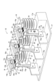
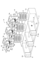
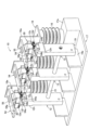
図1に示すように、接地開閉器10は、接離可能に設けられた可動子12及び固定子14を備えている。可動子12及び固定子14は、三相分として3組設けられており、本実施の形態では、3組の可動子12及び固定子14は、概略同一構造が採用される。可動子12及び固定子14は、接触状態(図2参照)で通電(閉路)し、図1に示す離間状態で通電を遮断(開路)するものである。ここで、本実施の形態では、接地開閉器10は空気中(大気中)で電流を遮断する気中開閉器とされ、配電盤の内部等に設置される。
As shown in FIG. 1, the
接地開閉器10は、3組の可動子12及び固定子14に対応する位置に設けられた3体のがいし16と、3体のがいし16が立設されるベース部材17とを備えている。更に、接地開閉器10は、3体のがいし16の上端側に設けられたブラケット状の支持部材18と、ベース部材17上に設けられて可動子12を回動可能に支持する回動支持部19とを備えている。支持部材18は、固定子14の基端側を支持する支持壁18aを備えて形成されている。
The
固定子14は、平板状の接続部14aと、接続部14aの下面に連なって形成されて可動子12の後述する接触部12bが接触する摺接部14bとを備えている。接続部14aは、先端側が摺接部14bより突出しており、この突出した部分にて不図示の回路や母線等が接続される。摺接部14bは、直線方向に延びる形状を備え、可動子12の接触部12bに接触する部分が概略半円柱状に膨らむ形状を備えている。
The
ベース部材17は、がいし16の設置部分が高くなるように隆起部17aを備えて形成されている。また、隆起部17aの手前側となるベース部材17の上面側に、回動支持部19を形成する3体の起立壁19aが連なって形成されている。回動支持部19は、それぞれの起立壁19aに回転可能に連結された3体の回転壁19bを備え、回転壁19bに可動子12の基端側が支持されている。
The
可動子12は、銅等によって形成される一対のブレード部材(導電体)12aを備えている。一対のブレード部材12aは、先端側の離間幅が基端側の離間幅より大きくなるように概略クランク状に屈曲形成されている。また、一対のブレード部材12aの先端側では、相互に接近する方向に膨らんだ形状に設けられ、かかる膨らんだ部分が固定子14に接触する接触部12bとされる。
The
可動子12は、圧縮コイルばねによって構成される接圧ばね(弾性部材)12cを備えている。接圧ばね12cは、一対のブレード部材12aに相互に接近する方向の弾性力を加えており、一対のブレード部材12aの離れる方向への変位に対して制動している。
The
具体的には、接圧ばね12cは、一対のブレード部材12aそれぞれの外面側二箇所位置に設けられ、該二箇所それぞれで一対のブレード部材12aを貫通するボルト12dに挿入されている(図3A参照)。ボルト12dの先端側には、ナット12eが螺合されており、ボルト12dの頭部とブレード部材12a外面との間、ナット12eとブレード部材12a外面との間それぞれに接圧ばね12cが圧縮された状態で配設されている。また、一対のブレード部材12aの先端側の内面間には連結筒12fが介在され、かかる連結筒12fの内部にボルト12dが挿通される。なお、ボルト12dの頭部とナット12eの位置関係は逆にしてもよい。
Specifically, the
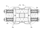
図2は、第1の実施の形態に係る接地開閉器の閉路状態の概略斜視図である。図2にも示すように、可動子12において、一対のブレード部材12aは、連結板12gによって基端側において連結されて一体化されている。連結板12gの図2中上端側では、上から見てコ字状の磁性部材30が2体支持されている。磁性部材30は、鉄材等の磁性体によって構成され、接圧ばね12cよりブレード部材12aの基端側に設けられる。
FIG. 2 is a schematic perspective view of the closed state of the earthing switch according to the first embodiment. As also shown in FIG. 2, in the
可動子12は、一対のブレード部材12aのうちの一方が回転壁19bに連結されて回動可能となっている。具体的には、可動子12は、図1に示す横方向に倒伏した状態から回動することで、該回転の軌跡に沿って先端側が上昇し、更に回動が進行して図2に示す縦方向に起立した状態で固定子14の先端側に可動子12の先端側が接触する。図2の可動子12及び固定子14の接触状態で、一対のブレード部材12aが固定子14の摺接部14bを挟み込みつつ摺接部14bと接触部12bとが接触するようになる。
The
3体の可動子12は、その基端側において接続軸部21を介して接続され、同じタイミングで同じ回転角度で回動するようになっている。また、接続軸部21は銅等の導電体によって形成され、3体の可動子12に対して電気的に導通している。接続軸部21は、不図示の配線等を介して接地されており、可動子12が接地電位に設定される。
The three
続いて、本実施の形態の磁性部材30の構成について、図3Aを参照しつつ説明する。図3Aは、本実施の形態の可動子を先端側から見た説明図である。図3Aに示すように、本実施の形態では、1体の可動子12に対し、同一形状に形成されて向きが異なる2体の磁性部材30が設けられる。ここで、磁性部材30では、一対のブレード部材12aによる固定子14(図1参照)の挟み込み方向つまり図3A中左右方向にて、一対のブレード部材12aで挟まれる内側空間Sが形成される。磁性部材30において、内側空間Sに位置して図3A中上下方向に延びる領域が主部31とされる。また、磁性部材30にて、内側空間Sの外部で主部31の図3中上下両端に連なり、且つ、ブレード部材12aにおける図3中上下方向(一対のブレード部材12aの挟み込み方向と交差する方向)両側近傍に形成される領域が側部32とされる。従って、磁性部材30は、それぞれのブレード部材12aを内側と幅方向両側とから囲うように設けられる。一方の磁性部材30の側部32と他方の磁性部材30の側部32とは、図3中上下方向両側で互いに離れる方向(図3中左右方向)に延伸している。
Next, the configuration of the
本実施の形態においては、図2に示すように可動子12及び固定子14を接触して閉路状態とすることで、それらに短絡電流を通電させることができる。接地開閉器10では、誤投入される場合、具体的には、固定子14が接続されている母線が課電状態で可動子12を投入動作して閉路されたり、かかる母線が閉路状態で課電されたりする場合を想定し、これに対応できる構成が必要になる。誤投入時には、可動子12に流れる電流が大電流になると、可動子12の接触部12bが固定子14の摺接部14bから離れる方向の反発力が発生する。かかる反発力によって、接触部12bが摺接部14bから離れると、接地不能や発弧による損傷のおそれがあるので、これを解消すべく、接圧ばね12cによって接触部12bを摺接部14bに押し付ける付勢力を加えている。
In the present embodiment, as shown in FIG. 2, the short-circuit current can be applied to the
接圧ばね12cによる付勢力を大きくする程、接触部12bが摺接部14bから離れ難くなって接地不能や損傷の発生を回避できるようになるが、接触部12bと摺接部14bとが接触する状態での可動子12における回動動作の操作負荷が大きくなる。このため、可動子12の動作用の駆動機構(不図示)にて、強度向上や動作に必要なばねが大きくなり、装置全体の大型化、複雑化を招来することとなる。
As the biasing force of the
ここで、比較構造として、本実施の形態の可動子12の構成から磁性部材30を省略した図4に示す構成について検討する。図4は、比較構造の可動子における磁束分布の説明図である。比較構造にて、閉路状態として通電すると、図4に示すように、可動子12にて紙面手前から奥行方向に流れる電流(短絡電流)によって、可動子12の中央部を中心として同心円上に分布するよう電流磁界の磁束Bcが発生する。
Here, as a comparative structure, the structure shown in FIG. 4 in which the
図3Bは、第1の実施の形態の可動子における磁束分布の説明図である。これに対し、本実施の形態では、可動子12に流れる電流の向きは比較構造と同じとなるが、図3Bに示すように、磁束Baの分布を比較構造の磁束Bcに対し変更することができる。具体的には、鉄材からなる磁性部材30自体に磁束Baを集中させることができる。これにより、特に、磁性部材30の主部31に磁束Baが集磁し、ブレード部材12aから見て、一対のブレード部材12aが相互に接近する方向側で磁束Baの分布が疎となり、その反対側で磁束Baの分布が密となる。かかる磁束Baの分布によって、一対のブレード部材12aが相互に接近する方向(図3B中の白矢印で示す方向)の電磁吸引力(ローレンツ力)が作用し、接触部12b及び摺接部14b(図1参照)間の接圧向上を通じて、それらの反発及び離間を防止することができる。
FIG. 3B is an explanatory diagram of magnetic flux distribution in the mover according to the first embodiment. On the other hand, in the present embodiment, the direction of the current flowing through the
このような電磁吸引力は、可動子12に通電した場合にだけ発生するものであり、通電しない正常運転時に、かかる電磁吸引力は発生しない。従って、接圧ばね12cの付勢力(弾性力)ひいては可動子12の操作負荷を維持しつつ、接触部12b及び摺接部14bの反発及び離間を防止することができる。従って、可動子12の駆動機構を含む装置全体の大型化、複雑化の回避と、短絡電流通電時の可動子12と固定子14との反発の抑制とを同時に達成することができる。
Such an electromagnetic attractive force is generated only when the
また、図3Bに示す磁束Baにあっては、ブレード部材12aの同図中上下両側にて磁性部材30の側部32に集中でき、ブレード部材12a周りにて磁束Baの発生位置の安定化を図ってブレード部材12aに作用する磁気吸引力が安定することを期待できる。
In addition, the magnetic flux Ba shown in FIG. 3B can be concentrated on the
[第2の実施の形態]
次に、本発明の第2の実施の形態について図5及び図6を参照して説明する。なお、以下の説明において、第1の実施の形態と同一若しくは同等の構成部分については同一符号を用いる場合があり、説明を省略若しくは簡略にする場合がある。
[Second embodiment]
Next, a second embodiment of the present invention will be described with reference to FIGS. 5 and 6. FIG. In the following description, the same reference numerals may be used for components that are the same as or equivalent to those in the first embodiment, and the description may be omitted or simplified.
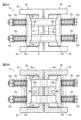
図5は、第2の実施の形態に係る接地開閉器の開路状態の概略斜視図である。図6は、第2の実施の形態に係る接地開閉器の閉路状態の概略斜視図である。図5及び図6に示すように、第2の実施の形態では、第1の実施の形態に対し、挟み込む構造を固定子54に設け、固定子54によって可動子12を挟み込み可能としている。
FIG. 5 is a schematic perspective view of an open circuit state of the earthing switch according to the second embodiment. FIG. 6 is a schematic perspective view of the closed state of the earthing switch according to the second embodiment. As shown in FIGS. 5 and 6, in the second embodiment, unlike the first embodiment, the
第2の実施の形態において、可動子12は、板状に形成されつつ、先端側が膨出した形状の頭部12hを有するように設けられている。
In the second embodiment, the
固定子54は、平板状の接続部55の下面に対し、第1の実施の形態における可動子12の先端側と同様の構造を設けて構成される。固定子54は、下側を開放する一対のブレード部材(導電体)54aを備えている。一対のブレード部材54aの先端側では、相互に接近する方向に膨らむ接触部54bが形成され、かかる接触部54bが可動子12の頭部12hを挟み込みつつ接触する。そして、固定子54は、一対のブレード部材54aに相互に接近する方向の力を加える構成として、第1の実施の形態と概略同一構造の接圧ばね12c、ボルト12d、ナット12e、連結筒12f、連結板12gを有している。
The
固定子54において、一対のブレード部材54aの基端側が連結板54gによって連結されている。連結板54gの図5中下端側では、第1の実施の形態と同様の形態、材質からなる磁性部材30が支持されている。磁性部材30は、接圧ばね12cよりブレード部材54aの基端側に設けられる。
In the
第2の実施の形態においては、閉路状態で固定子54のブレード部材54aに電流が流れ、かかる電流によって発生する磁束を磁性部材30自体に集中させることができる。
これにより、第1の実施の形態と同様に、一対のブレード部材54aが相互に接近する方向の電磁吸引力が作用するようになる。この結果、接触部54b及び可動子12の頭部12h間の接圧向上を通じて、それらの反発及び離間を抑制することができる。
In the second embodiment, current flows through the
As a result, as in the first embodiment, an electromagnetic attraction force acts in the direction in which the pair of
なお、本発明は上記各実施の形態に限定されず、種々変更して実施することが可能である。上記実施の形態において、添付図面に図示されている大きさや形状、向きなどについては、これに限定されず、本発明の効果を発揮する範囲内で適宜変更することが可能である。その他、本発明の目的の範囲を逸脱しない限りにおいて適宜変更して実施することが可能である。 It should be noted that the present invention is not limited to the above embodiments, and can be implemented with various modifications. In the above embodiments, the sizes, shapes, directions, etc. shown in the accompanying drawings are not limited to these, and can be changed as appropriate within the scope of exhibiting the effects of the present invention. In addition, it is possible to carry out by appropriately modifying the present invention as long as it does not deviate from the scope of the purpose of the present invention.
可動子12及び固定子14、54の構造や向きについては、上記と同様の機能を有する限りにおいて、種々の変更が可能である。例えば、可動子12を直線方向に動作して固定子14と切離可能にする等、接地開閉器10の設置スペースや通電容量等に応じることができる。
The structure and orientation of the
また、上記接地開閉器10を気中開閉器とした場合を説明したが、絶縁性ガス(消弧性ガス)や真空の環境下で可動子12及び固定子14、54が開閉する開閉器とすることを妨げるものでない。
In addition, although the
また、磁性部材30は、一対のブレード部材12a、54aで挟まれる内側空間Sに少なくとも一部が設けられて磁束を集中できる限りにおいて、種々の変更が可能である。例えば、上記各実施の形態にて磁性部材30をコ字状としたが、これをV字状、U字状に湾曲若しくは屈曲させた形状としたり、図3A中上下両側の側部32を省略した構成としたりしてもよい。更に、上記各実施の形態では、ブレード部材12a、54aの挟み方向に磁性部材30を2体並べたが、これらを連結してH字状の単一の磁性部材30を配置したり、内側空間Sの内部に単一の平坦な片状或いは板状の磁性部材30を配置したりしてもよい。かかる形態の磁性部材30において、複数の板材を組み合わせた構造とすることで、製作コストを低減することができる。
Further, the
10 接地開閉器
12 可動子
12a ブレード部材(導電体)
12c 接圧ばね(弾性部材)
14 固定子
30 磁性部材
31 主部
32 側部
54 固定子
54a ブレード部材(導電体)
S 内側空間(空間)
10
12c Contact pressure spring (elastic member)
S inner space (space)
Claims (4)
前記固定子は、前記接触状態で前記可動子を挟み込みつつ接触する部分を形成する一対の導電体と、
前記一対の導電体の挟み込み方向にて、該一対の導電体で挟まれる空間に少なくとも一部が設けられる磁性部材とを備え、
前記磁性部材は、通電時に発生する磁束を該磁性部材自体に集中させることで、前記一対の導電体に相互に接近する方向の電磁吸引力を作用させることを特徴とする接地開閉器。 A grounding switch provided with a stator and a mover that are arranged to be contactable and detachable and that are energized in a contact state and cut off the energization in a separated state,
The stator includes a pair of conductors forming contact portions while sandwiching the mover in the contact state;
a magnetic member at least partially provided in a space sandwiched between the pair of conductors in the sandwiching direction of the pair of conductors,
The earthing switch is characterized in that the magnetic member concentrates magnetic flux generated when energized to the magnetic member itself, thereby exerting an electromagnetic attractive force in a direction in which the pair of conductors approach each other.
前記可動子は、前記接触状態で前記固定子を挟み込みつつ接触する部分を形成する一対の導電体と、
前記一対の導電体の挟み込み方向にて、該一対の導電体で挟まれる空間に少なくとも一部が設けられる磁性部材とを備え、
前記磁性部材は、前記一対の導電体で挟まれる空間に位置する主部と、該空間の外部で前記主部に連なり且つ前記挟み込み方向と交差する方向の両側で互いに離れる方向に延伸して形成される側部とを備え、通電時に発生する磁束を該磁性部材自体に集中させることで、前記一対の導電体に相互に接近する方向の電磁吸引力を作用させることを特徴とする接地開閉器。 A grounding switch provided with a stator and a mover that are arranged to be contactable and detachable and that are energized in a contact state and cut off the energization in a separated state,
the mover includes a pair of conductors that sandwich the stator in the contact state and form contact portions;
a magnetic member at least partially provided in a space sandwiched between the pair of conductors in the sandwiching direction of the pair of conductors,
The magnetic member has a main portion positioned in a space sandwiched between the pair of conductors, and a magnetic member connected to the main portion outside the space and extending in directions away from each other on both sides in a direction intersecting the sandwiching direction. and a magnetic flux generated at the time of energization is concentrated on the magnetic member itself, thereby exerting an electromagnetic attraction force in a direction in which the pair of conductors approach each other. .
Priority Applications (2)
| Application Number | Priority Date | Filing Date | Title |
|---|---|---|---|
| JP2019025525A JP7225890B2 (en) | 2019-02-15 | 2019-02-15 | earthing switch |
| JP2022193637A JP7428228B2 (en) | 2019-02-15 | 2022-12-02 | earthing switch |
Applications Claiming Priority (1)
| Application Number | Priority Date | Filing Date | Title |
|---|---|---|---|
| JP2019025525A JP7225890B2 (en) | 2019-02-15 | 2019-02-15 | earthing switch |
Related Child Applications (1)
| Application Number | Title | Priority Date | Filing Date |
|---|---|---|---|
| JP2022193637A Division JP7428228B2 (en) | 2019-02-15 | 2022-12-02 | earthing switch |
Publications (2)
| Publication Number | Publication Date |
|---|---|
| JP2020135983A JP2020135983A (en) | 2020-08-31 |
| JP7225890B2 true JP7225890B2 (en) | 2023-02-21 |
Family
ID=72278999
Family Applications (2)
| Application Number | Title | Priority Date | Filing Date |
|---|---|---|---|
| JP2019025525A Active JP7225890B2 (en) | 2019-02-15 | 2019-02-15 | earthing switch |
| JP2022193637A Active JP7428228B2 (en) | 2019-02-15 | 2022-12-02 | earthing switch |
Family Applications After (1)
| Application Number | Title | Priority Date | Filing Date |
|---|---|---|---|
| JP2022193637A Active JP7428228B2 (en) | 2019-02-15 | 2022-12-02 | earthing switch |
Country Status (1)
| Country | Link |
|---|---|
| JP (2) | JP7225890B2 (en) |
Citations (3)
| Publication number | Priority date | Publication date | Assignee | Title |
|---|---|---|---|---|
| JP2000125426A (en) | 1998-10-16 | 2000-04-28 | Fuji Electric Co Ltd | Gas-insulated switchgear |
| JP2002051414A (en) | 2000-08-02 | 2002-02-15 | Toshiba Corp | Composite gas-insulated switchgear |
| JP2013251964A (en) | 2012-05-31 | 2013-12-12 | Hitachi Ltd | Switchgear or method for assembling switchgear |
Family Cites Families (3)
| Publication number | Priority date | Publication date | Assignee | Title |
|---|---|---|---|---|
| JPS5323555U (en) * | 1976-08-05 | 1978-02-28 | ||
| JPS629626Y2 (en) * | 1978-05-23 | 1987-03-06 | ||
| JPS6110406Y2 (en) * | 1980-09-27 | 1986-04-03 |
-
2019
- 2019-02-15 JP JP2019025525A patent/JP7225890B2/en active Active
-
2022
- 2022-12-02 JP JP2022193637A patent/JP7428228B2/en active Active
Patent Citations (3)
| Publication number | Priority date | Publication date | Assignee | Title |
|---|---|---|---|---|
| JP2000125426A (en) | 1998-10-16 | 2000-04-28 | Fuji Electric Co Ltd | Gas-insulated switchgear |
| JP2002051414A (en) | 2000-08-02 | 2002-02-15 | Toshiba Corp | Composite gas-insulated switchgear |
| JP2013251964A (en) | 2012-05-31 | 2013-12-12 | Hitachi Ltd | Switchgear or method for assembling switchgear |
Also Published As
| Publication number | Publication date |
|---|---|
| JP2023016917A (en) | 2023-02-02 |
| JP7428228B2 (en) | 2024-02-06 |
| JP2020135983A (en) | 2020-08-31 |
Similar Documents
| Publication | Publication Date | Title |
|---|---|---|
| KR101377342B1 (en) | Circuit breaker | |
| JP5826379B2 (en) | Switchgear | |
| JP4866949B2 (en) | Vacuum insulated switchgear | |
| US8455775B2 (en) | Power transmission apparatus for high voltage load breaker switch | |
| CN103262200A (en) | Circuit breaker | |
| JP2010119243A (en) | Vacuum switchgear | |
| US10727008B2 (en) | Contact device for an electrical switch, and electrical switch | |
| CN102592906B (en) | Medium-pressure and high-capacity DC circuit breaker contact terminal system for improving short time endurance capability | |
| US8575508B2 (en) | Current switch | |
| CN1897376A (en) | Vacuum insulation switch apparatus | |
| TW200522111A (en) | Disconnector | |
| CN104321847A (en) | Circuit breaker for direct-current circuit and circuit breaker device for direct-current circuit | |
| JP2012142236A (en) | Switch unit and switchgear | |
| CN2840304Y (en) | Indoor high-voltage three-station isolating switch | |
| JP6990294B2 (en) | Circuit breaker for gas-insulated switchgear | |
| US9502195B2 (en) | Switching device | |
| JP7225890B2 (en) | earthing switch | |
| JP5815449B2 (en) | Vacuum circuit breaker | |
| JP7070178B2 (en) | Ground switch | |
| JP2022012663A (en) | Ground switch | |
| KR102367825B1 (en) | High Speed Earthing Switch of Gas Insulated Switchgear | |
| JPH10308147A (en) | Generator switch | |
| JP6977427B2 (en) | Ground switchgear and gas-insulated switchgear | |
| JP4693736B2 (en) | Gas insulated disconnect switch | |
| CN105161346A (en) | Single-pole isolated grounding switch |
Legal Events
| Date | Code | Title | Description |
|---|---|---|---|
| A621 | Written request for application examination |
Free format text: JAPANESE INTERMEDIATE CODE: A621 Effective date: 20220114 |
|
| A977 | Report on retrieval |
Free format text: JAPANESE INTERMEDIATE CODE: A971007 Effective date: 20220916 |
|
| A131 | Notification of reasons for refusal |
Free format text: JAPANESE INTERMEDIATE CODE: A131 Effective date: 20221004 |
|
| A521 | Request for written amendment filed |
Free format text: JAPANESE INTERMEDIATE CODE: A523 Effective date: 20221202 |
|
| TRDD | Decision of grant or rejection written | ||
| A01 | Written decision to grant a patent or to grant a registration (utility model) |
Free format text: JAPANESE INTERMEDIATE CODE: A01 Effective date: 20230110 |
|
| A61 | First payment of annual fees (during grant procedure) |
Free format text: JAPANESE INTERMEDIATE CODE: A61 Effective date: 20230123 |
|
| R150 | Certificate of patent or registration of utility model |
Ref document number: 7225890 Country of ref document: JP Free format text: JAPANESE INTERMEDIATE CODE: R150 |