KR20150006858A - Device for electrically driving a longitudinal adjustment mechanism for a vehicle seat - Google Patents
Device for electrically driving a longitudinal adjustment mechanism for a vehicle seat Download PDFInfo
- Publication number
- KR20150006858A KR20150006858A KR20147032623A KR20147032623A KR20150006858A KR 20150006858 A KR20150006858 A KR 20150006858A KR 20147032623 A KR20147032623 A KR 20147032623A KR 20147032623 A KR20147032623 A KR 20147032623A KR 20150006858 A KR20150006858 A KR 20150006858A
- Authority
- KR
- South Korea
- Prior art keywords
- rail
- steering mechanism
- individual
- planetary gear
- longitudinal steering
- Prior art date
Links
- 230000007246 mechanism Effects 0.000 title claims abstract description 43
- 239000000463 material Substances 0.000 claims description 11
- 238000000034 method Methods 0.000 claims description 9
- 230000002441 reversible effect Effects 0.000 claims description 3
- 230000001360 synchronised effect Effects 0.000 claims description 3
- 230000000284 resting effect Effects 0.000 claims 1
- 229910000831 Steel Inorganic materials 0.000 description 10
- 239000010959 steel Substances 0.000 description 10
- 230000000712 assembly Effects 0.000 description 7
- 238000000429 assembly Methods 0.000 description 7
- 229910052782 aluminium Inorganic materials 0.000 description 6
- XAGFODPZIPBFFR-UHFFFAOYSA-N aluminium Chemical compound [Al] XAGFODPZIPBFFR-UHFFFAOYSA-N 0.000 description 6
- 238000005096 rolling process Methods 0.000 description 6
- 230000008901 benefit Effects 0.000 description 3
- 230000008859 change Effects 0.000 description 2
- 230000004048 modification Effects 0.000 description 2
- 238000012986 modification Methods 0.000 description 2
- 238000007493 shaping process Methods 0.000 description 2
- 229910000838 Al alloy Inorganic materials 0.000 description 1
- 229910000851 Alloy steel Inorganic materials 0.000 description 1
- FYYHWMGAXLPEAU-UHFFFAOYSA-N Magnesium Chemical compound [Mg] FYYHWMGAXLPEAU-UHFFFAOYSA-N 0.000 description 1
- 229910000861 Mg alloy Inorganic materials 0.000 description 1
- 239000000654 additive Substances 0.000 description 1
- 230000000996 additive effect Effects 0.000 description 1
- 230000002146 bilateral effect Effects 0.000 description 1
- 230000001419 dependent effect Effects 0.000 description 1
- 238000006073 displacement reaction Methods 0.000 description 1
- 238000001125 extrusion Methods 0.000 description 1
- 239000011777 magnesium Substances 0.000 description 1
- 229910052749 magnesium Inorganic materials 0.000 description 1
- 229910052751 metal Inorganic materials 0.000 description 1
- 239000002184 metal Substances 0.000 description 1
- 230000008569 process Effects 0.000 description 1
- 239000012791 sliding layer Substances 0.000 description 1
Images


Classifications
-
- B—PERFORMING OPERATIONS; TRANSPORTING
- B60—VEHICLES IN GENERAL
- B60N—SEATS SPECIALLY ADAPTED FOR VEHICLES; VEHICLE PASSENGER ACCOMMODATION NOT OTHERWISE PROVIDED FOR
- B60N2/00—Seats specially adapted for vehicles; Arrangement or mounting of seats in vehicles
- B60N2/02—Seats specially adapted for vehicles; Arrangement or mounting of seats in vehicles the seat or part thereof being movable, e.g. adjustable
- B60N2/0224—Non-manual adjustments, e.g. with electrical operation
- B60N2/02246—Electric motors therefor
-
- B—PERFORMING OPERATIONS; TRANSPORTING
- B60—VEHICLES IN GENERAL
- B60N—SEATS SPECIALLY ADAPTED FOR VEHICLES; VEHICLE PASSENGER ACCOMMODATION NOT OTHERWISE PROVIDED FOR
- B60N2/00—Seats specially adapted for vehicles; Arrangement or mounting of seats in vehicles
- B60N2/02—Seats specially adapted for vehicles; Arrangement or mounting of seats in vehicles the seat or part thereof being movable, e.g. adjustable
-
- B—PERFORMING OPERATIONS; TRANSPORTING
- B60—VEHICLES IN GENERAL
- B60N—SEATS SPECIALLY ADAPTED FOR VEHICLES; VEHICLE PASSENGER ACCOMMODATION NOT OTHERWISE PROVIDED FOR
- B60N2/00—Seats specially adapted for vehicles; Arrangement or mounting of seats in vehicles
-
- B—PERFORMING OPERATIONS; TRANSPORTING
- B60—VEHICLES IN GENERAL
- B60N—SEATS SPECIALLY ADAPTED FOR VEHICLES; VEHICLE PASSENGER ACCOMMODATION NOT OTHERWISE PROVIDED FOR
- B60N2/00—Seats specially adapted for vehicles; Arrangement or mounting of seats in vehicles
- B60N2/02—Seats specially adapted for vehicles; Arrangement or mounting of seats in vehicles the seat or part thereof being movable, e.g. adjustable
- B60N2/04—Seats specially adapted for vehicles; Arrangement or mounting of seats in vehicles the seat or part thereof being movable, e.g. adjustable the whole seat being movable
- B60N2/06—Seats specially adapted for vehicles; Arrangement or mounting of seats in vehicles the seat or part thereof being movable, e.g. adjustable the whole seat being movable slidable
- B60N2/067—Seats specially adapted for vehicles; Arrangement or mounting of seats in vehicles the seat or part thereof being movable, e.g. adjustable the whole seat being movable slidable by linear actuators, e.g. linear screw mechanisms
-
- B—PERFORMING OPERATIONS; TRANSPORTING
- B60—VEHICLES IN GENERAL
- B60N—SEATS SPECIALLY ADAPTED FOR VEHICLES; VEHICLE PASSENGER ACCOMMODATION NOT OTHERWISE PROVIDED FOR
- B60N2/00—Seats specially adapted for vehicles; Arrangement or mounting of seats in vehicles
- B60N2/02—Seats specially adapted for vehicles; Arrangement or mounting of seats in vehicles the seat or part thereof being movable, e.g. adjustable
- B60N2/04—Seats specially adapted for vehicles; Arrangement or mounting of seats in vehicles the seat or part thereof being movable, e.g. adjustable the whole seat being movable
- B60N2/06—Seats specially adapted for vehicles; Arrangement or mounting of seats in vehicles the seat or part thereof being movable, e.g. adjustable the whole seat being movable slidable
- B60N2/07—Slide construction
- B60N2/0702—Slide construction characterised by its cross-section
- B60N2/0712—H or double T-shaped
-
- B—PERFORMING OPERATIONS; TRANSPORTING
- B60—VEHICLES IN GENERAL
- B60N—SEATS SPECIALLY ADAPTED FOR VEHICLES; VEHICLE PASSENGER ACCOMMODATION NOT OTHERWISE PROVIDED FOR
- B60N2/00—Seats specially adapted for vehicles; Arrangement or mounting of seats in vehicles
- B60N2/02—Seats specially adapted for vehicles; Arrangement or mounting of seats in vehicles the seat or part thereof being movable, e.g. adjustable
- B60N2/0224—Non-manual adjustments, e.g. with electrical operation
- B60N2/02246—Electric motors therefor
- B60N2/02253—Electric motors therefor characterised by the transmission between the electric motor and the seat or seat parts
Abstract
본 발명은 차량 시트용 길이방향 조종 기구를 전기 구동하기 위한 장치에 관한 것이며, 상기 기구는 두 개의 개별적인 레일(1)들을 포함한다. 본 발명에 따라서, 차량 시트용 길이방향 조종 기구를 전기 구동하기 위한 장치는 각각의 개별적인 레일(1)을 위한 별도의 전기 구동 수단(6)을 포함하며, 각각의 구동 수단(6)은 전기기계 가동식 유성 기어 조립체로서 설계된다.The present invention relates to an apparatus for electrically driving a longitudinal steering mechanism for a vehicle seat, the mechanism comprising two separate rails (1). According to the invention, an apparatus for electrically driving a longitudinal steering mechanism for a vehicle seat comprises separate electric drive means (6) for each individual rail (1), each drive means (6) And is designed as a movable planetary gear assembly.
Description
본 발명은 차량 시트용 길이방향 조정 기구를 전기적으로 구동하기 위한 장치에 관한 것이다.
The present invention relates to an apparatus for electrically driving a longitudinal direction adjusting mechanism for a vehicle seat.
종래 기술에서, 차량 시트의 전기 구동식 길이방향 조정 기구들은 길이?향 조정 기구의 두 개의 개별적인 레일들 사이의 소위 모터 브릿지(motor bridge) 내에 배열되는 개별적인 구동 모터에 의해 구동된다. 이런 경우에, 구동 샤프트들은 두 개의 개별적인 레일들 사이에 구동 모터의 토크를 분배하며 각각의 경우에 적어도 스핀들과 워엄 기어로 형성되는 기어 유닛을 구동한다. 그와 같은 길이방향 조정 기구들은 예를 들어, DE 35 19 058 A1 및 DE 10 2006 045 483 A1에 개시되어 있다.
In the prior art, the electrically driven longitudinal adjustment mechanisms of the vehicle seat are driven by separate drive motors arranged in so-called motor bridges between two separate rails of the longitudinal adjustment mechanism. In this case, the drive shafts distribute the torque of the drive motor between the two individual rails and, in each case, drive at least the gear unit formed of the spindle and the worm gear. Such longitudinal adjustment mechanisms are disclosed, for example, in DE 35 19 058 A1 and
본 발명의 목적은 차량 시트의 길이방향 조정 기구를 전기 구동하기 위한 종래 기술에 대해서 개선된 장치를 명시하고자 하는 것이다.
It is an object of the present invention to specify an improved apparatus for the prior art for electrically driving the longitudinal adjustment mechanism of a vehicle seat.
차량 시트의 길이방향 조정 기구를 전기 구동하기 위한 기구에 관하여, 상기 목적은 특허청구범위 제 1 항에 개시된 특징들에 의해 달성된다.
With respect to the mechanism for electrically driving the longitudinal adjustment mechanism of the vehicle seat, this object is achieved by the features disclosed in
본 발명의 유리한 개량들이 종속항들의 요지를 형성한다.
Advantageous refinements of the invention form the gist of the dependent claims.
본 발명에 따라서, 두 개의 개별적인 레일들을 갖는 차량 시트의 길이방향 조정 기구를 전기 구동하기 위한 장치는 각각의 개별적인 레일을 위한 별개의 전기 구동 수단을 포함하며, 그 전기 구동 수단은 각각의 경우에 전기기계 가동식 유성 기어 조립체로서 구성된다. 이는 길이방향 조정 기구의 간결한 전기 구동을 허용한다.
In accordance with the present invention, an apparatus for electrically driving a longitudinal adjustment mechanism of a vehicle seat having two individual rails includes separate electric drive means for each individual rail, the electric drive means comprising, in each case, And is configured as a machine-movable planetary gear assembly. This allows a simple electrical drive of the longitudinal adjustment mechanism.
본 발명에 따라서, 전기 구동 수단으로서 전기기계 가동식 유성 기어 조립체들의 사용에 의해서, 동기 구동(synchronous drive)은 전기기계 가동식 유성 기어 조립체를 작동하는데 요구되는 제어 전자기기들의 결과로써, 부가 비용의 제어 및/또는 조절 대책들 없이 길이방향 조종 기구들의 개별적인 양측 레일들에 허용되며, 상기 제어 전자기기들은 유리하게 별도의 센서들 없이 작동한다.
In accordance with the present invention, by the use of electromechanical planetary gear assemblies as electric drive means, a synchronous drive is used to control and control the additive cost as a result of the control electronics required to operate the electromechanical planetary gear assembly / RTI > are allowed on the respective bilateral rails of the longitudinal steering mechanisms without any adjustment measures, and the control electronics advantageously operate without separate sensors.
이런 경우에, 직렬 배열되는 복수의 개별적인 유성 기어들을 포함하는 개별적인 유성 기어 조립체 또는 구동 수단으로서 개별적인 유성 기어를 갖춘 복수의 유성 기어 조립체들이 두 개의 개별적인 레일들을 위해 제공될 수 있으며, 여기서 유성 기어 조립체(조립체들)는 개별적인 레일들을 동기적으로 구동한다. 워엄과 스핀들을 갖춘 종래의 길이방향 조종 기구들에 대하여, 본 발명에 따른 길이방향 조종 기구는 스핀들 없이 구성된다.
In this case, a plurality of planetary gear assemblies with individual planetary gears as individual planetary gear assemblies or drive means comprising a plurality of individual planetary gears arranged in series may be provided for the two individual rails, wherein the planetary gear assemblies Assemblies) drive the individual rails synchronously. For conventional longitudinal steering instruments with worms and spindles, the longitudinal steering mechanism according to the invention is constructed without a spindle.
본 발명에 따라서, 본 발명에 따른 장치에 의해서 차량 시트의 전기 구동 길이방향 조종 기구의 중량은 상당히 감소되며 그의 조립은 유리한 방식으로 간단해 진다.
According to the present invention, the weight of the electric drive longitudinal steering mechanism of the vehicle seat is significantly reduced by the device according to the invention, and its assembly is simplified in an advantageous manner.
특히 유리하게, 차량 내의 두 개의 개별적인 레일들 사이의 레일 간격은 종래 모터 브릿지 및/또는 대응 구동 샤프트들을 바꿔야 함이 없이 가변 방식으로 적응될 수 있다. 이는 가변성을 증가시키며 동일한 구성의 개별적인 레일들을 다른 차량들에의 사용을 허용한다.
Particularly advantageously, the rail spacing between the two individual rails in the vehicle can be adapted in a variable manner without having to change the conventional motor bridge and / or the corresponding drive shafts. This increases variability and allows the use of individual rails of the same configuration in different vehicles.
편리하게, 일반적으로 모터 브릿지 및 관련 구동 샤프트들이 차량 시트 아래를 차지하고 차량 시트의 후방에 앉는 차량 점유자들을 위한 레그 룸(leg room)을 감소시키는 구조적 공간이 제거되어서 대응하는 레그 룸이 증가되며 차량 점유자들의 안락함이 증가된다. 유리한 실시예에서, 서랍을 위한 구조적 공간이 예를 들어 차량 시트 아래에 제공될 수 있다.
Conveniently, the structural space that reduces the legroom for vehicle occupants, which generally occupies the motor bridge and associated drive shafts underneath the vehicle seat and sits behind the vehicle seat, is eliminated, so that the corresponding legroom is increased and the vehicle occupant Comfort is increased. In an advantageous embodiment, a structural space for the drawer may be provided for example under the vehicle seat.
종래의 길이방향 스핀들의 제거에 의해서 레일 프로파일들의 선택을 변화시키기 위한 가능성이 더 커져서, 예를 들어, 더 경량이고/이거나 더 좁은 개별적인 레일들이 허용되는데, 이는 길이방향 스핀들이 레일 프로파일 내측에 배열되지 않기 때문이다.
The possibility of changing the choice of rail profiles by removing the conventional longitudinal spindle is increased, for example, allowing for the use of lighter and / or narrower individual rails, which allows the longitudinal spindles to be arranged inside the rail profile It is not.
유리한 실시예에서, 전기기계 가동식 유성 기어 조립체로서 구성되는 전기 구동 수단은 직렬로 배열되는 복수의 유성 기어들을 포함한다. 결과적으로, 특히 높은 토크들이 비교적으로 낮은 회전 속도들에서 생성될 수 있다. 복수의 유성 기어들을 갖춘 유성 기어 조립체로 형성되는 구동 유닛은 특히 간결하고 비용-효과적이다. 그와 같은 유성 기어 조립체는 예를 들어, 인용에 의해 본 발명에 포함되는 국제 특허 출원 WO 2012/152727 A1에 개시되어 있다.
In an advantageous embodiment, the electric drive means constituted as an electromechanical mobile planetary gear assembly comprises a plurality of planetary gears arranged in series. As a result, particularly high torques can be generated at relatively low rotational speeds. A drive unit formed of a planetary gear assembly with a plurality of planet gears is particularly compact and cost-effective. Such a planetary gear assembly is disclosed in, for example, International Patent Application WO 2012/152727 A1, which is incorporated herein by reference.
제 1 변형예에서, 전기기계 가동식 유성 기어 조립체는 길이방향 조종 기구의 각각의 개별적인 레일의 외측 레일에 고정되게 배열되며, 여기서 치형 로드(toothed rod)가 포지티브 재료 및/또는 넌-포지티브 연결에 의해 배열되고 길이방향 조종 기구의 각각의 개별적인 레일의 내측 레일에 적어도 부분적으로 고정된다. 따라서, 작동 중에 전기기계 가동식 유성 기어 조립체는 시트 하부구조물 및 차량 구조물에 고정적으로 커플링되며, 그에 의해서 전기 접속이 간단해진다.
In a first variant, the electromechanical movable planetary gear assembly is fixedly arranged on the outer rails of the respective individual rails of the longitudinal steering mechanism, wherein the toothed rods are connected by positive material and / or non-positive connection And is at least partially fixed to the inner rails of the respective individual rails of the longitudinal steering mechanism. Thus, during operation, the electromechanical movable planetary gear assembly is fixedly coupled to the seat undercarriage and the vehicle structure, thereby simplifying electrical connection.
이런 경우에, 전기기계 가동식 유성 기어 조립체는 외측 레일의 내측에 편리하게 배열될 수 있으며 가역적 방식으로 하나 이상의 모터 지지대에 의해 유지될 수 있다. 결과적으로, 전기기계 가동식 유성 기어 조립체는 직접적인 시야 밖의 차량 시트의 시트 표면 아래에 공간-절약 방식으로 배열된다.
In this case, the electromechanical mobile planetary gear assembly can be conveniently arranged inside the outer rail and can be held in one or more motor supports in a reversible manner. As a result, the electromechanical mobile planetary gear assembly is arranged in a space-saving manner beneath the seat surface of the vehicle seat out of direct view.
게다가, 전기기계 가동식 유성 기어 조립체는 외측 레일의 외측에 배열될 수 있으며 외측 레일의 기저부에 형성되는 대응하는 수용기 개구 내에 적어도 부분적으로 가역적으로 배열되고 유지될 수 있다. 결과적으로, 길이방향 조종 기구의 장착 상태에서조차도 전기기계 가동식 유성 기어 조립체로의 용이한 접근이 허용된다.
In addition, the electromechanical mobile planetary gear assembly may be arranged outside the outer rail and be at least partly reversibly arranged and held within a corresponding receiver opening formed in the base of the outer rail. As a result, even in the mounted state of the longitudinal steering mechanism, easy access to the electromechanical mobile planetary gear assembly is permitted.
제 2 변형예에서, 전기기계 가동식 유성 기어 조립체는 길이방향 조종 기구의 각각의 개별적인 레일의 내측 레일 상에 고정적으로 배열되며, 여기서 치형 로드가 포지티브 재료 및/또는 넌-포지티브 연결에 의해 배열되며 길이방향 조종 기구의 각각의 개별적인 레일의 외측 레일 상에 적어도 부분적으로 고정된다. 따라서, 작동 중에 전기기계 가동식 유성 기어 조립체는 차량 시트에 고정적으로 커플링되며 시트가 조종될 때 시트 하부구조물 및 차량 구조물에 대해 시트와 함께 이동한다.
In a second variant, the electromechanical mobile planetary gear assembly is fixedly arranged on the inner rails of each individual rail of the longitudinal steering mechanism, wherein the toothed rods are arranged by positive material and / or non-positive connection, Is at least partially fixed on the outer rails of each individual rail of the steering mechanism. Thus, during operation, the electromechanical mobile planetary gear assembly is fixedly coupled to the vehicle seat and moves with the seat relative to the seat structure and vehicle structure as the seat is manipulated.
이런 경우에, 전기기계 가동식 유성 기어 조립체는 유리하게, 내측 레일의 내측에 배열될 수 있으며 내측 레일 내에 형성되는 대응하는 수용기 개구 내에 적어도 부분적으로 가역적으로 배열되고 유지될 수 있다. 결과적으로, 전기기계 가동식 유성 기어 조립체는 직접적인 시야 밖의 차량 시트 의 시트 표면 아래에 공간-절약 방식으로 배열된다.
In this case, the electromechanical moveable planetary gear assembly may advantageously be arranged inside the inner rail and be at least partly reversibly arranged and held in a corresponding receptacle opening formed in the inner rail. As a result, the electromechanical mobile planetary gear assembly is arranged in a space-saving manner beneath the seat surface of the vehicle seat out of direct view.
각각의 개별적인 레일 상의 전기기계 가동식 유성 기어 조립체의 가역적 배열은 고장난 전기기계 가동식 유성 기어 조립체의 간단하고 복잡하지 않은 교체를 허용한다.
The reversible arrangement of the electromechanical movable planetary gear assemblies on each individual rail allows a simple and uncomplicated replacement of the failed electromechanical movable planetary gear assembly.
유리한 실시예에서, 외측 레일의 기저부에 홈이 형성되며, 상기 홈은 전기기계 가동식 유성 기어 조립체의 스퍼 기어(spur gear)에 대응하도록 형상화되며, 여기서 스퍼 기어는 그 홈의 내측에 적어도 부분적으로 배열되며, 치형 로드 및 카운터 홀더(counter holder)가 홈의 플랭크(frank)들 상에 일체로 형성되거나 형상화된다.
In an advantageous embodiment, a groove is formed in the base of the outer rail, the groove being shaped to correspond to a spur gear of an electromechanical planetary gear assembly, wherein the spur gear is at least partly arranged And a toothed rod and a counter holder are integrally formed or shaped on the franks of the groove.
대체 실시예에서, 하나 이상의 유지 부분이 내측 레일의 하단부 영역에 일체로 형성되거나 형상화되며, 전기 구동 수단이 상기 유지 부분 상에 놓이거나 그에 대해 적어도 부분적으로 지탱되며, 하나 이상의 추가의 유지 부분이 뒤로 구부러지도록 외측 레일의 기저부 상에 형상화되거나 배열되어서, 치형 로드 또는 카운터 홀더가 이러한 유지 부분 상에 배열된다.
In an alternative embodiment, the at least one holding portion is integrally formed or shaped in the lower end region of the inner rail, the electric driving means is placed on or at least partly supported on the holding portion, Shaped or arranged on the base of the outer rail to bend so that a toothed rod or counter holder is arranged on this holding part.
특히 바람직하게, 전기기계 가동식 유성 기어 조립체의 구동 샤프트 상에 회전 측면에서 고정적으로 배열되는 스퍼 기어에 의해서 전기 구동 수단과 개별적인 레일 사이에 힘이 전달되며, 상기 스퍼 기어는 치형 로드와 대응하도록 구성되고 그와 맞물림하도록 그 내부에서 결합한다.
Particularly preferably, a force is transmitted between the electric drive means and the individual rails by a spur gear fixedly arranged on the rotational side of the drive shaft of the electromechanical mobile planetary gear assembly, the spur gear being configured to correspond to the toothed rod And engages with it to engage it.
유리하게, 전기기계 가동식 유성 기어 조립체의 스퍼 기어는 그와 맞물리도록 제 2 치형 로드와 결합하는 추가의 기어 휠에 커플링될 수 있다. 따라서 더 큰 토크들이 전달될 수 있다. 게다가, 충돌의 경우에 안전성이 그와 같은 실시예에 의해 현저히 개선된다.
Advantageously, the spur gear of the electromechanical mobile planetary gear assembly can be coupled to an additional gear wheel that engages the second toothed rod to engage it. Therefore, larger torques can be delivered. In addition, in the event of a collision, safety is significantly improved by such an embodiment.
본 발명은 첨부된 대략적인 도면들을 참조하여 더 구체적으로 설명된다.
The present invention will be described in more detail with reference to the accompanying schematic drawings.
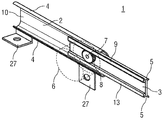
도 1은 제 1 변형예로 차량 시트의 길이방향 조종 기구의 레일 시스템의 전동식 이동가능한 개별적인 레일의 사시도를 개략적으로 도시하며, 여기서 전기 구동 수단이 차량 본체에 배열되고 레일 시스템은 스틸로 구성되며,
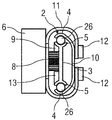
도 2는 외측 레일의 내측에 배열되는 전기 구동 수단을 갖춘 전기식 이동이능한 개별적인 레일의 단면도를 개략적으로 도시하며, 여기서 전기 구동 수단이 차량 본체에 배열되고 레일 시스템은 스틸로 구성되며,
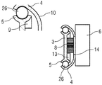
도 3은 외측 레일의 외측에 배열되는 전기 구동 수단을 갖춘 전기식 이동이능한 개별적인 레일의 단면도를 개략적으로 도시하며, 여기서 전기 구동 수단이 차량 본체에 배열되고 레일 시스템은 스틸로 구성되며,
도 4는 제 2 변형예로 차량 시트의 길이방향 조종 기구의 레일 시스템의 전동식 이동가능한 개별적인 레일의 사시도를 개략적으로 도시하며, 여기서 전기 구동 수단이 차량 본체에 배열되고 레일 시스템은 알루미늄으로 구성되며,
도 5는 외측 레일의 내측에 배열되는 전기 구동 수단을 갖춘 전기식 이동이능한 개별적인 레일의 단면도를 개략적으로 도시하며, 여기서 전기 구동 수단이 차량 본체에 배열되고 레일 시스템은 알루미늄으로 구성되며,
도 6은 외측 레일의 외측에 배열되는 전기 구동 수단을 갖춘 전기식 이동이능한 개별적인 레일의 단면도를 개략적으로 도시하며, 여기서 전기 구동 수단이 차량 본체에 배열되고 레일 시스템은 알루미늄으로 구성되며,
도 7은 제 1 변형예로 내측 레일의 내측에 배열되는 전기 구동 수단을 갖춘 전기식 이동이능한 개별적인 레일의 단면도를 개략적으로 도시하며, 여기서 전기 구동 수단이 차량 시트에 배열되고 레일 시스템은 스틸로 구성되며,
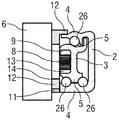
도 8은 제 2 변형예로 내측 레일의 내측에 배열되는 전기 구동 수단을 갖춘 전기식 이동이능한 개별적인 레일의 단면도를 개략적으로 도시하며, 여기서 전기 구동 수단이 차량 시트에 배열되고 레일 시스템은 스틸로 구성되며,
도 9는 제 3 변형예로 내측 레일의 내측에 배열되는 전기 구동 수단을 갖춘 전기식 이동이능한 개별적인 레일의 단면도를 개략적으로 도시하며, 여기서 전기 구동 수단이 차량 시트에 배열되고 레일 시스템은 스틸로 구성되며,
도 10은 제 1 변형예로 내측 레일의 내측에 배열되는 전기 구동 수단을 갖춘 도 4에 따른 전기식 이동이능한 개별적인 레일의 단면도를 개략적으로 도시하며, 여기서 전기 구동 수단이 차량 시트에 배열되고 레일 시스템은 알루미늄으로 구성되며,
도 11은 제 1 변형예로 내측 레일의 내측에 배열되는 전기 구동 수단을 갖춘 도 4에 따른 전기식 이동이능한 개별적인 레일의 단면도를 개략적으로 도시하며, 여기서 전기 구동 수단이 차량 시트에 배열되고 레일 시스템은 알루미늄으로 구성되며,
도 12는 2-부품 모터 지지대에 의해서 내측 레일의 내측에 배열되는 전기 구동 수단을 갖춘 도 1에 따른 전기식 이동이능한 개별적인 레일의 단면도를 개략적으로 도시하며, 여기서 전기 구동 수단이 차량 시트에 배열되고 레일 시스템은 스틸로 구성되며,
도 13은 2-부품 모터 지지대에 의해서 내측 레일의 내측에 배열되는 전기 구동 수단을 갖춘 도 1에 따른 전기식 이동이능한 개별적인 레일의 측면도를 개략적으로 도시하며, 여기서 전기 구동 수단이 차량 시트에 배열되고 레일 시스템은 스틸로 구성되며,
도 14는 두 개의 스퍼 기어 및 두 개의 치형 로드들을 갖춘 전기식 이동이능한 개별적인 레일의 변형예의 측면도를 개략적으로 도시한다.
1 schematically shows a perspective view of an electromagnetically movable individual rail of a rail system of a longitudinal steering mechanism of a vehicle seat according to a first variant wherein the electric drive means is arranged in the vehicle body and the rail system is constituted by steel,
Figure 2 schematically shows a cross-sectional view of an electrically movable individual rail with electric drive means arranged inside the outer rail, wherein the electric drive means is arranged in the vehicle body and the rail system is constituted by steel,
Fig. 3 schematically shows a cross-section of an electrically movable individual rail with electric drive means arranged outside the outer rail, in which the electric drive means are arranged in the vehicle body and the rail system is constituted by steel,
Fig. 4 schematically shows a perspective view of the electromagnetically movable individual rail of the rail system of the longitudinal steering mechanism of the vehicle seat as a second variant, wherein the electric drive means is arranged in the vehicle body and the rail system is composed of aluminum,
Figure 5 schematically shows a cross-sectional view of an electrically movable individual rail with electric drive means arranged inside the outer rail, wherein the electric drive means is arranged in the vehicle body and the rail system is made of aluminum,
Figure 6 schematically shows a cross-sectional view of an electrically movable individual rail with electric drive means arranged outside the outer rail, wherein the electric drive means is arranged in the vehicle body and the rail system is made of aluminum,
Fig. 7 schematically shows a cross-section of an electrically movable individual rail with electric drive means arranged inside the inner rail in a first variant, in which the electric drive means are arranged in the vehicle seat and the rail system is constituted by steel And,
Fig. 8 schematically shows a cross-sectional view of an electrically movable individual rail with electric drive means arranged inside the inner rail in a second variant, in which the electric drive means is arranged on the vehicle seat and the rail system is constituted by steel And,
Fig. 9 schematically shows a cross-sectional view of an electrically movable individual rail with electric drive means arranged inside the inner rail in a third variant, in which the electric drive means are arranged on the vehicle seat and the rail system is constituted by steel And,
Fig. 10 schematically shows a cross-sectional view of an electrically movable individual rail according to Fig. 4 with electric drive means arranged inside the inner rail in a first variant, in which the electric drive means are arranged in the vehicle seat, Is made of aluminum,
Fig. 11 schematically shows a cross-sectional view of an electrically movable individual rail according to Fig. 4 with an electric drive means arranged inside the inner rail in a first variant, in which the electric drive means are arranged on the vehicle seat and the rail system Is made of aluminum,
Figure 12 schematically shows a cross-sectional view of an individually movable, individually movable rail according to figure 1 with electric drive means arranged inside the inner rail by a two-part motor support, in which the electric drive means are arranged on the vehicle seat The rail system consists of steel,
Figure 13 schematically shows a side view of an individually movable, individually movable rail according to figure 1 with electric drive means arranged inside the inner rail by a two-part motor support, in which electric drive means are arranged on the vehicle seat The rail system consists of steel,
Figure 14 schematically shows a side view of a variant of an electrically movable individual rail with two spur gears and two toothed rods.
모든 도면들에서 서로 대응하는 부품들은 동일한 참조 번호들이 제공된다.
The parts corresponding to each other in all the drawings are given the same reference numerals.
도 1은 제 1 변형예로 차량 시트의 길이방향 조종 기구의, 더 상세하게 도시되지 않은, 특히 선형 또는 곡선 방식으로 연장하는 레일 시스템의 전동식 이동가능한 개별적인 레일(1)의 사시도를 개략적으로 도시한다.
1 schematically shows a perspective view of a motor-driven,
개별적인 레일(1)은 차량 점유자를 위치시키기 위해 차량의 길이방향으로 차량 시트의 시트 조종을 위한 레일 시스템의 부품이다. 그와 같은 레일 시스템은 종래의 레일 시스템으로서 구성되며 바람직하게, 차량 내의 양 측들에 그리고 차량 시트 상에 운행 방향으로 서로에 평행하게 배열되는 두 개의 개별적인 레일(1)들을 포함한다. 이런 경우에, 각각의 개별적인 레일(1)은 외측 레일(2) 및 내측 레일(3)을 포함한다.
The
이런 경우에, 종래의 체결 수단(27)이 외측 레일(2) 상에 배열될 수 있으며, 상기 체결 수단은 예를 들어, 태브(tab)들로서 구성되고 개별적인 레일(1)을 차량 본체에 체결하는 것을 허용한다.
In this case, the conventional fastening means 27 can be arranged on the
도 1에 도시된 외측 레일(2) 및 내측 레일(3)은 스틸 또는 스틸 합금으로 제작된다.
The
레일 시스템의 작동 위치에서 내측 레일(3)은 외측 레일(2) 내에 적어도 부분적으로 길이방향으로 변위가능한 방식으로 배열되고 안내된다.
In the operating position of the rail system, the
도시되지 않은 종래 방식의 외측 레일(2)은 차량의 차량 바닥에 체결되고 바람직하게 차량의 길이방향으로 정렬된다.
The conventional
종래의 차량 시트는 내측 레일(3) 상에 배열된다. 그러므로 외측 레일(2)에 대한 내측 레일(3)의 길이방향 변위에 의해서, 차량 시트는 차량 내에서 길이방향으로 변위될 수 있다.
The conventional vehicle seat is arranged on the
도 1에 따른 실시예에서, 외측 레일(2)은 바닥에서 그리고 상부에서 내측 레일(3)을 둘러싼다. 이런 경우에 외측 레일(2)은 두 개의 외측 림(limb)(4)을 갖춘 수직으로 C-형상인 프로파일(profile) 횡단면을 가진다.
In the embodiment according to Fig. 1, the
외측 레일(2) 내에 배열되는 내측 레일(3)의 단부 영역(5)들은 각각의 경우에 외측 레일(2)의 수용 레일 프로파일, 특히 외측 림(4)에 대응하도록 형상화된다. 이런 경우에, 내측 레일(3)의 단부 영역(5)들은 바람직하게 Y-형상 횡단면을 가진다.
The
최소 마찰에 의해 외측 레일(2)에 대해 내측 레일(3)을 안내하고 변위시키기 위해서, 종래의 롤링 본체(rolling body)(26)들이 도 2에 도시된 상부와 바닥에서 양측 레일(2,3)들 사이에 회전가능하게 배열된다. 바람직하게 종래의 스틸 볼(steel ball)들 또는 배럴-형상(barrel-shaped)의 롤링 본체들이 롤링 본체(26)들로서 사용된다.
In order to guide and displace the
상기 롤링 본체(26)들은 외측 레일(2)의 각각의 외측 림(4)과 내측 레일(3)의 단부 영역(5) 사이에서 돌며 결과적으로, 최소 마찰 및 감소된 힘으로 외측 레일(2)에 대한 내측 레일(3)의 운동을 허용한다.
The rolling
본 발명에 따라서, 길이방향 조종 기구의 각각의 개별적인 레일(1)은 별도의 전기 구동 수단(6)이 할당된다. 이런 경우에, 전기 구동 수단(6)은 전기기계 가동식 유성 기어 조립체, 특히 텀블 기어(tumble gear)로서 구성된다. 바람직한 변형예에서, 그와 같은 유성 기어 조립체는 복수의 유성 기어들을 포함할 수 있으며 비교적 낮은 회전 속도들에서 특히 높은 토크를 생성할 수 있다. 복수의 유성 기어들을 포함하는 유성 기어 조립체로 형성되는 구동 유닛은 특히 간결하고 비용-효과적이며 예를 들어, 국제 특허 출원 WO 2012/152727 A1에 개시되어 있다.
According to the invention, each individual rail (1) of the longitudinal steering mechanism is assigned a separate electric drive means (6). In this case, the electric drive means 6 is configured as an electromechanical mobile planetary gear assembly, in particular a tumble gear. In a preferred variant, such a planetary gear assembly may comprise a plurality of planet gears and may produce particularly high torque at relatively low rotational speeds. A drive unit formed from a planetary gear assembly including a plurality of planetary gears is particularly compact and cost effective and is disclosed, for example, in International Patent Application WO 2012/152727 A1.
도 1에 도시된 제 1 변형예에서, 전기 구동 유닛(6)은 길이방향 조종 기구의 개별적인 레일(1)의 외측 레일(2)에 고정되게 배열되며 따라서 작동 중에 시트 하부구조물 및 차량 구조물에 고정적으로 커플링된다.
In the first variant shown in Fig. 1, the
힘은 이런 경우에 전기 구동 수단(6)의 구동 샤프트(7) 상에 배열되는 스퍼 기어(8)에 의해서 전기 구동 수단(6)과 개별적인 레일(1) 사이로 전달되며, 상기 스퍼 기어는 내측 레일(3)에 적어도 부분적으로 배열되는 치형 로드(9)에 작용한다.
The force is transmitted between the electric drive means 6 and the
치형 로드(9) 및 스퍼 기어(8)는 서로 대응하도록 종래대로 형상화되며, 특히 대응 톱니는 동일한 모듈(module)이다. 이런 경우에 치형 로드(9) 및 스퍼 기어(8)는 서로 맞물리도록 종래 방식으로 결합한다.
The
치형 로드(9)는 예를 들어, 포지티브 재료 및/또는 넌-포지티브 연결에 의해 고정되고 내측 레일(3), 특히 단부 영역(5)들 중의 하나의 영역에 배열된다.
The
본 발명에 따라 전기 구동 수단(6)으로서 전기기계 가동식 유성 기어 조립체들을 사용함으로서, 길이방향 조종 기구의 양측 개별적인 레일(1)들의 동기 구동은 전기기계 가동식 유성 기어 조립체의 작동에 요구되는 제어 전자기기들로 인해서, 부가 비용의 대책들 없이 허용된다.
By using electromechanical planetary gear assemblies as electric drive means 6 in accordance with the present invention, the synchronous drive of the
특히 유리하게, 차량 내의 두 개의 개별적인 레일(1)들 사이의 레일 간격은 모터 브릿지 및/또는 대응 구동 샤프트들의 바꿈 없이 가변 방식으로 적응될 수 있다. 이는 가변성을 증가시키고 상이한 차량들에 개별적인 레일(1)들의 사용을 허용한다.
Particularly advantageously, the rail spacing between the two
종래의 길이방향 스핀들의 제거에 의해서, 개별적인 레일(1)에 대한 레일 프로파일들의 선택을 변경하기 위한 더 큰 가능성이 있어서 예를 들어 더 경량 및/또는 더 좁은 개별적인 레일(1)들이 허용된다.
By eliminating the conventional longitudinal spindles, for example, lighter and / or narrower
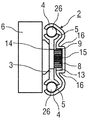
도 2는 외측 레일(2)의 내측에 배열되는 전기 구동 수단(6)을 갖춘, 도 1에 따른 전기식 이동이능한 개별적인 레일(1)의 단면도를 개략적으로 도시한다. 이런 경우에, 기저부(10)로부터 이격되는 외측 레일(2)의 C-형상 프로파일의 개방 측은 외측 레일(2)의 내측으로 표시된다.
Fig. 2 schematically shows a cross-section of an individually
본 실시예에서, 전기 구동 수단(6)은 모터 지지대(11) 상에 종래 방식으로 유지된다. 모터 지지대(11)는 이런 경우에 상부 및/또는 바닥에서 개별적인 레일(1)을 둘러싸도록 구성되고 하나 이상, 바람직하게 두 개의 종래의 체결 수단(12), 예를 들어 스크류들에 의해서 외측 레일(2)의 기저부(10)에 가역적으로 유지된다.
In this embodiment, the electric drive means 6 is held in a conventional manner on the
도시 않은 대체 실시예에서, 모터 지지대(11)는 외측 레일(2)에 재료 연결에 의해서 배열될 수 있으며 전기 구동 수단(6)은 종래 방식으로 모터 지지대(11)에 가역적으로 체결된다.
In an alternative embodiment not shown, the
바람직하게, 카운터 홀더(13)는 치형 로드(9)와 반대의 단부 영역(5)인 레일(3)의 단부 영역(5)에 배열되며, 상기 카운터 홀더는 치형 로드(9)와 반대인 측면에서 스퍼 기어(8)에 작용하고 스퍼 기어(8)가 치형 로드(9)로부터 리프팅되는(lifted) 것을 방지한다.
Preferably the
결과적으로, 스퍼 기어(8) 및 치형 로드(9)는 그에 매우 높은 힘이 작용하는 경우조차도, 예를 들어 충돌의 경우조차도 포지티브 결합하며 따라서 차량 본체에 대한 개별적인 레일(1)의 운동 및 차량 시트의 운동을 방지한다.
As a result, the
더 상세하게 도시하지 않은 특히 유리한 실시예에서, 스퍼 기어(8)의 방향으로 향하는 카운터 홀더(13)의 표면에는 카운터 홀더(13)의 마모를 감소시키는 미끄럼 층이 제공된다.
In a particularly advantageous embodiment not shown in more detail, on the surface of the
도 3은 외측 레일(2)의 외측에 배열되는 전기 구동 수단(6)을 갖춘, 도 1에 따른 전기식 이동이능한 개별적인 레일(1)의 단면도를 개략적으로 도시한다. 이런 경우에, 기저부(10)는 외측 레일(2)의 외측으로서 표시된다.
Fig. 3 schematically shows a cross-sectional view of an individually
이러한 변형예는 전기 구동 수단(6)이 외측 레일(2)의 기저부(10)에 형성되는 대응 수용기 개구(14) 내에 적어도 부분적으로 배열되고 유지되는 차이가 있지만 도 2의 변형예에 실질적으로 대응한다.
This variant has the advantage that the electric drive means 6 is at least partly arranged and held in the corresponding receptacle opening 14 formed in the
도 4는 제 1 변형예로 차량 시트의 길이방향 조종 기구의, 더 상세히 도시 않은 레일 시스템의 전기식 이동이능한 개별적인 레일(1)의 사시도를 개략적으로 도시한다.
Fig. 4 schematically shows a perspective view of an electromagnetically movable
이러한 변형예는 외측 레일(2) 및 내측 레일(3)이 경량 금속, 예를 들어 알루미늄 또는 알루미늄 합금 또는 마그네슘 또는 마그네슘 합금으로 제작되고 이러한 재료의 요건들에 따라 형상화되는 차이가 있지만 도 1에 따른 변형예에 실질적으로 대응한다. 이런 경우에, 특히 외측 레일(2)의 외측 림(4) 및 내측 레일(3)의 단부 영역(5)들은 대응하게 보강된다.
This variant has the advantage that the
외측 레일(2) 및 내측 레일(3)은 이런 경우에 바람직하게 압출 공정으로 제조된다.
The
예를 들어, 표면 압력 및 그로부터 초래되는 마모를 최소화하기 위해서, 서로 인접한 2열들의 롤링 본체(26)들이 내측 레일(3)의 하부 면에 배열된다.
For example, in order to minimize the surface pressure and the wear resulting therefrom, two rows of adjacent rolling
도 5는 외측 레일(2)의 내측에 배열되는 전기 구동 수단(6)을 갖춘, 도 4에 따른 전기식 이동이능한 개별적인 레일(1)의 단면도를 개략적으로 도시한다. 이러한 변형예는 전방 면 및/또는 상부 면 상의 모터 지지대(11)가 외측 레일 상의 종래의 체결 수단(12)에 의해 유지되는 차이가 있지만 도 2에 따른 변형예에 실질적으로 대응한다.
Fig. 5 schematically shows a cross-sectional view of an individually
도시되지 않은 대체 실시예에서, 모터 지지대(11)는 외측 레일(2) 상에 재료 연결에 의해 배열될 수 있으며 전기 구동 수단(6)이 종래 방식으로 모터 지지대(11)에 가역적으로 체결된다.
In an alternative embodiment, which is not shown, the
도 6은 외측 레일(2)의 외측에 배열되는 전기 구동 수단(6)을 갖춘, 도 4에 따른 전기식 이동이능한 개별적인 레일(1)의 단면도를 개략적으로 도시한다.
Fig. 6 schematically shows a cross-sectional view of an individually
이런 변형예는 전기 구동 수단(6)이 외측 레일(2)의 기저부(10)에 형성되는 대응 수용기 개구(14) 내에 적어도 부분적으로 배열되고 유지되는 차이가 있지만 도 5에 따른 변형예에 실질적으로 대응한다.
This variant has the advantage that the electric drive means 6 is at least partly arranged and held in the corresponding receptacle opening 14 formed in the
제 2 변형예에서, 전기 구동 수단(6)은 길이방향 조종 기구의 개별적인 레일(1)의 내측 레일(3)에 고정적으로 배열되며, 따라서 작동 중에 차량 시트에 고정적으로 커플링되고 시트가 조종될 때 시트 하부구조물 및 차량 구조물에 대해 그와 함께 이동한다.
In a second variant, the electric drive means 6 are fixedly arranged on the
힘은 이런 경우에 전기 구동 수단(6)의 구동 샤프트(7)에 배열되는 스퍼 기어(8)에 의해서 전기 구동 수단(6)과 개별적인 레일(1) 사이로 전달되며, 상기 스퍼 기어는 외측 레일(2)에 적어도 부분적으로 배열되는 치형 로드(9)에 작용한다.
The force is transmitted between the electric drive means 6 and the
치형 로드(9) 및 스퍼 기어(8)는 서로 대응하도록 종래 방식으로 형성되며, 특히 대응 톱니는 동일한 모듈이다.
The
치형 로드(9)는 예를 들어, 포지티브 재료 및/또는 넌-포지티브 연결에 의해서 외측 레일(2)에 고정적으로 배열된다.
The
도 7은 제 1 변형예로, 내측 레일(3)의 내측에 배열되는 전기 구동 수단(6)을 갖춘, 도 1에 따른 전기식 이동이능한 개별적인 레일(1)의 단면도를 개략적으로 도시한다. 이런 경우에, 외측 레일(2)의 기저부(10)로부터 이격되는 내측 레일(3)의 측면은 내측 레일(3)의 내측으로서 표시된다.
Fig. 7 schematically shows a cross-sectional view of an electrically movable
전기 구동 수단(6)은 예를 들어, 관통-구멍으로서 내측 레일(3)에 형성되는 대응 수용기 개구(14) 내에 적어도 부분적으로 배열되고 유지된다.
The electric drive means 6 is at least partly arranged and held in a corresponding receptacle opening 14 formed in the
스퍼 기어(8)는 이런 경우에 그와 함께 맞물리도록 치형 로드(9)와 결합하도록 배열된다. 치형 로드(9) 및 카운터 홀더(13)는 이런 변형예에서 별도의 구성요소들로서 구성되며 포지티브 재료 및/또는 넌-포지티브 연결에 의해서 프레임에 고정됨으로써 외측 레일(2)의 실질적으로 평탄한 기저부(10)에 체결된다.
The
도 8은 제 2 변형예로, 내측 레일(3)의 내측에 배열되는 전기 구동 수단(6)을 갖춘, 도 1에 따른 전기식 이동이능한 개별적인 레일(1)의 단면도를 개략적으로 도시한다.
Fig. 8 schematically shows a cross-sectional view of an electrically drivable
이런 변형예는 홈(15)이 외측 레일(2)의 기저부(10) 내에 형성되며, 상기 홈이 스퍼 기어(8)에 대응하도록 형상화되는 차이점이 있지만 도 7에 따른 변형예에 실질적으로 대응한다. 스퍼 기어(8)는 이런 경우에, 홈(15)의 내측에 적어도 부분적으로 배열된다.
This variant corresponds substantially to the variant according to FIG. 7, although the groove 15 is formed in the
따라서, 치형 로드(9) 및 카운터 홀더(13)는 홈(15)의 플랭크(16)들 상에 일체로 형성되거나 형상화된다. 이런 일체형 형성 또는 형상화는 바람직한 변형예에서 하나의 피스(piece)로 발생될 수 있다.
Thus, the
도 9는 제 3 변형예로, 내측 레일(3)의 내측에 배열되는 전기 구동 수단(6)을 갖춘, 도 1에 따른 전기식 이동이능한 개별적인 레일(1)의 단면도를 개략적으로 도시한다.
Fig. 9 schematically shows a cross section of an electrically movable
이런 변형예는 유지 부분(17)이 내측 레일(3)의 하부 단부 영역(5)에 일체로 형성되거나 형상화되며, 전기 구동 수단(6)이 상기 유지 부분에 대해 적어도 부분적으로 지탱되거나 그에 놓이는 차이가 있지만 도 7에 따른 변형예에 실질적으로 대응한다.
This variant is characterized in that the retaining
게다가, 외측 레일(2)의 기저부(10) 상에는 두 개의 추가의 유지 부분(18)이 뒤로 구부러지도록 형상화되거나 배열되어서, 치형 로드(9)는 이들 유지 부분(18)들 중의 하나에 배열되는 반면에, 카운터 홀더(13)는 다른 유지 부분(18)에 배열된다.
In addition, on the
도 10은 제 1 변형예로, 내측 레일(3)의 내측에 배열되는 전기 구동 수단(6)을 갖춘, 도 4에 따른 전기식 이동이능한 개별적인 레일(1)의 단면도를 개략적으로 도시한다. 이런 경우에, 외측 레일(2)의 기저부(10)로부터 이격되는 내측 레일(3)의 측면은 내측 레일(3)의 내측으로서 표시된다.
Fig. 10 schematically shows a cross-sectional view of an electromagnetically movable
전기 구동 수단(6)은 예를 들어, 관통-구멍으로서 내측 레일(3) 내에 형성되는 대응 수용기 개구(14) 내에 적어도 부분적으로 배열되고 유지된다.
The electric drive means 6 is at least partly arranged and held in a corresponding receptacle opening 14 formed in the
이런 경우에, 수용기 개구(14)는 압전식 액추에이터 드라이브(piezoelectric actuator drive)(6) 쪽으로 계단형(step-like) 방식으로 넓어질 수 있다.
In this case, the
이런 경우에 스퍼 기어(8)는 그와 함께 맞물리도록 치형 로드(9)와 결합되도록 배열된다. 치형 로드(9) 및 카운터 홀더(13)는 이런 변형예에서 별도의 구성요소들로서 구성되고 포지티브 재료 및/또는 넌-포지티브 연결에 의해 고정됨으로써 외측 레일(2)의 실질적으로 평탄한 기저부(10)에 체결된다.
In this case the
이런 경우에, 유지 부분(18)은 카운터 홀더(13)가 이런 유지 부분(18)에 배열되도록 뒤로 구부러지도록 외측 레일(2)의 기저부(10)에 형상화되거나 배열된다.
In this case the retaining
도 11은 제 2 변형예로, 내측 레일(3)의 내측에 배열되는 전기 구동 수단(6)을 갖춘, 도 4에 따른 전기식 이동이능한 개별적인 레일(1)의 단면도를 개략적으로 도시한다.
Fig. 11 schematically shows a cross-sectional view of an electromagnetically movable
이런 변형예는 치형 로드(9)가 두 개의 추가의 유지 부분(18)이 뒤로 구부러지도록 외측 레일(2)의 기저부(10)에 형상화되거나 배열되어서 이들 유지 부분(18)들 중의 하나에 배열되는 반면에 카운터 홀더(13)가 다른 유지 부분(18)에 배열되는 차이가 있지만 도 10에 따른 변형예에 실질적으로 대응한다.
This variant is such that the
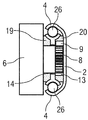
도 12는 2부품 모터 지지대(11)에 의해서 내측 레일(3)의 내측에 배열되는 전기 구동 수단(6)을 갖춘, 도 1에 따른 전기식 이동이능한 개별적인 레일(1)의 단면도를 개략적으로 도시한다.
Fig. 12 schematically shows a cross-section of an individually
그와 같은 2-부품 모터 지지대(11)는 개별적인 제 1 부품(19) 및 개별적인 제 2 부품(20)을 포함한다. 이런 경우에, 개별적인 제 1 부품(19)은 내측 레일(3)의 내측에 배열되며 개별적인 제 2 부품(20)은 반대 측에 배열된다. 따라서 내측 레일(3)은 2-부품 모터 지지대(11)의 개별적인 부품(19,20)들에 의해 부분적으로 동봉된다.
Such a two-
2-부품 모터 지지대(11)의 개별적인 부품(19,20)들에 있어서, 각각 경우에 수용기 개구(21)는 관통-개구 또는 관통-보어로서 형성되며, 여기서 이들 수용기 개구(21)들은 내측 레일(3) 내의 수용기 개구(4) 및 수용될 전기 구동 수단(6)의 부분에 대응하도록 구성된다. 전기 구동 수단(6)을 배열하기 위해서, 개별적인 부품(19,20)들의 수용기 개구(21) 및 내측 레일(3)의 수용기 개구(14)는 일치하는 방식(congruent manner)으로 배열된다.
In the
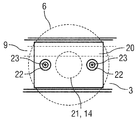
도 13은 2-부품 모터 지지대(11)에 의해서 내측 레일(3)의 내측에 배열되는 전기 구동 수단(6)을 갖춘, 도 1에 따른 전기식 이동이능한 개별적인 레일(1)의 측면도를 개략적으로 도시한다.
Fig. 13 schematically shows a side view of an electromagnetically movable
수용기 개구(14,21)들의 양 측들에서 각각의 경우에 체결 부분(22)이 내측 레일(3)의 길이방향으로 대응하는 구성요소들 내에, 예를 들어 나사형성된 보어로서 형성된다. 내측 레일(3)에 압전 액추에이터 드라이브를 장착하는 동안에, 종래의 체결 수단(23), 예를 들어 스크류들이 체결 부분(22)들 내에 배열되며 이런 방식으로 2-부품 모터 지지대(11)의 개별적인 부품(19,20)들, 내측 레일(3) 및 전기 구동 수단(6)을 함께 연결한다.
On both sides of the
개별적인 부품(20)은 바람직하게, 치형 로드(9)를 안내하기 위한 홈을 가진다.
The
도 14는 두 개의 스퍼 기어(8,24)들 및 두 개의 치형 로드(9,25)를 갖춘 전기식 이동이능한 개별적인 레일(1)의 변형예에 대한 측면도를 개략적으로 도시한다.
Fig. 14 schematically shows a side view of a variant of an electrically movable
이러한 유리한 실시예에서, 전기 구동 수단(6)의 스퍼 기어(8)는 더 큰 토크가 이런 방식으로 전달될 수 있도록 개별적인 레일(1) 상의 카운터 홀더(13)의 위치에 배열되는 제 2 치형 로드(25)에 작용하는 추가의 스퍼 기어(24)에 커플링된다.
In this advantageous embodiment the
스퍼 기어(8,24)들은 서로 대응하도록 구성되고 서로 맞물리도록 결합하여서, 전기 구동 수단(6)의 회전 운동이 스퍼 기어(8)로부터 스퍼 기어(24)로 전달된다.
The spur gears 8 and 24 are configured to correspond to each other and to be engaged with each other so that the rotational movement of the electric drive means 6 is transmitted from the
이런 경우에, 스퍼 기어(8)는 치형 로드(9)와 결합하며 스퍼 기어(24)는 제 2 치형 로드(25)와 결합하여 서로 맞물리게 된다. 이런 경우에, 치형 로드(9) 및 치형 로드(25)는 개별적인 레일(1)의 동일한 구성요소 상에 함께 배열되어 동일한 방향으로 이동한다.
In this case, the
1 : 개별적인 레일
2 : 외측 레일
3 : 내측 레일
4 : 외측 림
5 : 단부 영역
6 : 전기 구동 수단
7 : 구동 샤프트
8 : 스퍼 기어
9 : 치형 로드
10 : 기저부
11 : 모터 지지대
12 : 체결 수단
13 : 카운터 홀더
14 : 수용기 개구
15 : 홈
16 : 플랭크
17 : 유지 부분
18 : 추가의 유지 부분
19 : 개별적인 제 1 부품
20 : 개별적인 제 2 부품
21 : 수용기 개구
22 : 체결 부분
23 : 체결 수단
24 : 추가의 스퍼 기어
25 : 치형 로드
26 : 롤링 본체1: Individual rails
2: outer rail
3: inner rail
4: lateral limb
5: End area
6: Electric drive means
7: drive shaft
8: Spur gear
9: Toothed rod
10:
11: Motor support
12: fastening means
13: Counter holder
14: Receptor opening
15: Home
16: Flank
17:
18: additional retaining portion
19: individual first part
20: individual secondary part
21: Receptor opening
22: fastening portion
23: fastening means
24: additional spur gear
25: Toothed rod
26: Rolling body
Claims (9)
상기 전기 구동 수단(6)은 개별적인 양측 레일(1)들의 동기 구동을 허용하는, 직렬로 배열되는 복수의 유성 기어들을 포함하는 전기기계 가동식 유성 기어 조립체로서 구성되는,
길이방향 조종 기구를 전기 구동하기 위한 장치.
An apparatus for electrically driving a longitudinal steering mechanism of a vehicle seat having two individual rails (1), comprising separate electric drive means (6) for each individual rail (1)
The electric drive means (6) is configured as an electromechanical mobile planetary gear assembly comprising a plurality of planetary gears arranged in series, allowing synchronous drive of the respective two-sided rails (1)
An apparatus for electrically driving a longitudinal steering mechanism.
상기 전기기계 가동식 유성 기어 조립체는 길이방향 조종 기구의 각각의 개별적인 레일(1)의 외측 레일(2)에 고정적으로 배열되며, 치형 로드(9)는 포지티브 재료 및/또는 넌-포지티브 연결에 의해 배열되고 길이방향 조종 기구의 각각의 개별적인 레일(1)의 내측 레일(3)에 적어도 부분적으로 고정되는,
길이방향 조종 기구를 전기 구동하기 위한 장치.
The method according to claim 1,
The electromechanical movable planetary gear assembly is fixedly arranged on an outer rail (2) of each individual rail (1) of a longitudinal steering mechanism and the toothed rod (9) is arranged by a positive material and / or non-positive connection And at least partly fixed to the inner rail (3) of each individual rail (1) of the longitudinal steering mechanism,
An apparatus for electrically driving a longitudinal steering mechanism.
상기 전기기계 가동식 유성 기어 조립체는 가역적인 방식으로, 외측 레일(2)의 내측에 배열되고 하나 이상의 모터 홀더(11)에 의해 유지되는,
길이방향 조종 기구를 전기 구동하기 위한 장치.
3. The method of claim 2,
The electromechanical movable planetary gear assembly is arranged in a reversible manner, inside the outer rail (2) and held by one or more motor holders (11)
An apparatus for electrically driving a longitudinal steering mechanism.
상기 전기기계 가동식 유성 기어 조립체는 외측 레일(2)의 외측에 배열되며 외측 레일(2)의 기저부(10) 내에 형성되는 대응 수용기 개구(14) 내에 적어도 부분적으로 가역적으로 배열되고 유지되는,
길이방향 조종 기구를 전기 구동하기 위한 장치.
3. The method of claim 2,
The electromechanical movable planetary gear assembly is arranged at the outside of the outer rail 2 and is at least partly reversibly arranged and held in a corresponding receptacle opening 14 formed in the base 10 of the outer rail 2,
An apparatus for electrically driving a longitudinal steering mechanism.
상기 전기기계 가동식 유성 기어 조립체는 길이방향 조종 기구의 각각의 개별적인 레일(1)의 내측 레일(3)에 고정적으로 배열되며, 상기 치형 로드(9)는 포지티브 재료 및/또는 넌-포지티브 연결에 의해서 배열되고 길이방향 조종 기구의 각각의 개별적인 레일(1)의 외측 레일(2) 상에 적어도 부분적으로 고정되는,
길이방향 조종 기구를 전기 구동하기 위한 장치.
The method according to claim 1,
The electromechanical movable planetary gear assembly is fixedly arranged on an inner rail (3) of each individual rail (1) of a longitudinal steering mechanism and the toothed rod (9) is connected by positive material and / or non-positive connection Arranged at least partly on the outer rail (2) of each individual rail (1) of the longitudinal steering mechanism,
An apparatus for electrically driving a longitudinal steering mechanism.
상기 전기기계 가동식 유성 기어 조립체는 내측 레일(3)의 내측에 배열되며 상기 내측 레일(3) 내에 형성되는 대응 수용기 개구(14) 내에 적어도 부분적으로 가역적으로 배열되고 유지되는,
길이방향 조종 기구를 전기 구동하기 위한 장치.
6. The method of claim 5,
The electromechanical movable planetary gear assembly is arranged at an inner side of the inner rail (3) and is at least partially reversibly arranged and held in a corresponding receptacle opening (14) formed in the inner rail (3)
An apparatus for electrically driving a longitudinal steering mechanism.
상기 외측 레일(2)의 기저부(10) 내에 홈(15)이 형성되며, 상기 홈은 전기기계 가동식 유성 기어 조립체의 스퍼 기어(8)에 대응하도록 형상화되며, 상기 스퍼 기어(8)는 홈(15)의 내측에 적어도 부분적으로 배열되며 상기 치형 로드(9) 및 카운터 홀더(13)는 홈(15)의 플랭크(16)들에 일체로 형성되거나 형상화되며, 상기 내측 레일(3)의 하단부 영역(5) 상에 하나 이상의 유지 부분(17)이 일체로 형성되거나 형상화되며, 상기 전기 구동 수단(6)은 상기 유지 부분에 적어도 부분적으로 지탱되거나 그에 놓여지며 하나 이상의 추가 유지 부분(18)은 뒤로 굽혀지도록 외측 레일(2)의 기저부(10)에 형상화되거나 배열되어서, 상기 치형 로드(9) 또는 카운터 홀더(13)가 이런 유지 부분(18) 상에 배열되는,
길이방향 조종 기구를 전기 구동하기 위한 장치.
The method according to claim 5 or 6,
A groove 15 is formed in the base 10 of the outer rail 2 and is shaped to correspond to the spur gear 8 of the electromechanical planetary gear assembly, 15 and the toothed rod 9 and the counter holder 13 are integrally formed or shaped in the flank 16 of the groove 15 and the lower end region of the inner rail 3, Characterized in that at least one holding part (17) is integrally formed or shaped on the holding part (5), the electric driving means (6) being at least partly supported or resting on the holding part and one or more additional holding parts Wherein said toothed rod (9) or counter holder (13) is arranged on such a retaining portion (18) so as to be bent or arranged in the base (10) of the outer rail (2)
An apparatus for electrically driving a longitudinal steering mechanism.
상기 전기기계 가동식 유성 기어 조립체의 구동 샤프트(7) 상에 회전 측면에서 고정적으로 배열되는 스퍼 기어(8)에 의해서 전기 구동 수단(6)과 개별적인 레일(1) 사이로 힘이 전달되며, 상기 스퍼 기어는 치형 로드(9)에 대응하도록 구성되고 그와 함께 맞물리도록 내부에 결합되는,
길이방향 조종 기구를 전기 구동하기 위한 장치.
8. The method according to any one of claims 1 to 7,
A force is transmitted between the electric drive means 6 and the individual rails 1 by means of the spur gear 8 fixedly arranged on the rotational side on the drive shaft 7 of the electromechanical movable planetary gear assembly, Is configured to correspond to the toothed rod (9) and is internally coupled to engage therewith,
An apparatus for electrically driving a longitudinal steering mechanism.
상기 전기기계 가동식 유성 기어 조립체의 스퍼 기어(8)는 그와 함께 맞물리도록 제 2 치형 로드(25)와 결합되는 추가 기어 휠(24)에 커플링되는,
길이방향 조종 기구를 전기 구동하기 위한 장치.
9. The method according to any one of claims 1 to 8,
The spur gear (8) of the electromechanical mobile planetary gear assembly is coupled to an additional gear wheel (24) coupled with a second toothed rod (25) to engage therewith.
An apparatus for electrically driving a longitudinal steering mechanism.
Applications Claiming Priority (5)
| Application Number | Priority Date | Filing Date | Title |
|---|---|---|---|
| DE102012007760.2 | 2012-04-20 | ||
| DE102012007760 | 2012-04-20 | ||
| DE102012212142.0A DE102012212142B4 (en) | 2012-04-20 | 2012-07-11 | Device for the electric drive of a longitudinal adjustment device of a vehicle seat |
| DE102012212142.0 | 2012-07-11 | ||
| PCT/EP2013/058138 WO2013156580A1 (en) | 2012-04-20 | 2013-04-19 | Device for electrically driving a longitudinal adjustment mechanism for a vehicle seat |
Publications (1)
| Publication Number | Publication Date |
|---|---|
| KR20150006858A true KR20150006858A (en) | 2015-01-19 |
Family
ID=49290242
Family Applications (1)
| Application Number | Title | Priority Date | Filing Date |
|---|---|---|---|
| KR20147032623A KR20150006858A (en) | 2012-04-20 | 2013-04-19 | Device for electrically driving a longitudinal adjustment mechanism for a vehicle seat |
Country Status (8)
| Country | Link |
|---|---|
| US (1) | US20150069807A1 (en) |
| EP (1) | EP2838757A1 (en) |
| JP (1) | JP2015514631A (en) |
| KR (1) | KR20150006858A (en) |
| CN (1) | CN104245410A (en) |
| DE (1) | DE102012212142B4 (en) |
| IN (1) | IN2014DN08705A (en) |
| WO (1) | WO2013156580A1 (en) |
Families Citing this family (31)
| Publication number | Priority date | Publication date | Assignee | Title |
|---|---|---|---|---|
| JP6168970B2 (en) * | 2013-06-16 | 2017-07-26 | 株式会社デルタツーリング | Power seat slide device and vehicle seat |
| KR20160121816A (en) * | 2015-04-13 | 2016-10-21 | 현대자동차주식회사 | Sliding armrest device for vehicle |
| CN106324974A (en) * | 2016-10-20 | 2017-01-11 | 安徽协创物联网技术有限公司 | Stereo panorama camera |
| DE102016224512A1 (en) * | 2016-12-08 | 2018-06-14 | Brose Fahrzeugteile Gmbh & Co. Kg, Coburg | Vehicle seat assembly with a floor rail side arranged drive means |
| DE102017211113A1 (en) * | 2016-12-15 | 2018-06-21 | Adient Us Llc | LENGTH ADJUSTMENT DEVICE FOR A SEAT, IN PARTICULAR AIRPORT SEAT, AND SEAT, IN PARTICULAR FLUGGASTSITZ |
| JP2019098916A (en) * | 2017-12-01 | 2019-06-24 | トヨタ紡織株式会社 | Slide device |
| CN109878384A (en) * | 2017-12-01 | 2019-06-14 | 丰田纺织株式会社 | Carriage |
| DE102018203195A1 (en) * | 2018-03-02 | 2019-09-05 | Adient Aerospace Llc | Longitudinal adjustment device for a seat, in particular aircraft seat, and seat |
| US10926667B2 (en) | 2018-05-04 | 2021-02-23 | Lear Corporation | Track assembly |
| US11358497B2 (en) | 2018-05-04 | 2022-06-14 | Lear Corporation | Track system having a rolling member |
| US11040639B2 (en) | 2018-05-04 | 2021-06-22 | Lear Corporation | Track assembly |
| US10882420B2 (en) | 2019-03-08 | 2021-01-05 | Lear Corporation | Track assembly |
| US11040638B2 (en) | 2018-05-04 | 2021-06-22 | Lear Corporation | Track assembly |
| US10562414B2 (en) | 2018-05-04 | 2020-02-18 | Lear Corporation | Track assembly |
| US10906431B2 (en) | 2018-05-04 | 2021-02-02 | Lear Corporation | Track assembly |
| CN113056388B (en) * | 2018-10-19 | 2023-04-07 | 麦格纳座椅公司 | Removable seat for use with long track assembly |
| US11225201B2 (en) | 2018-12-10 | 2022-01-18 | Lear Corporation | Track assembly |
| US11440482B2 (en) | 2018-12-10 | 2022-09-13 | Lear Corporation | Track assembly |
| US10855037B2 (en) | 2018-12-17 | 2020-12-01 | Lear Corporation | Support assembly with a support member and a track assembly |
| US11613220B2 (en) | 2018-12-17 | 2023-03-28 | Lear Corporation | Electrical assembly |
| US11117538B2 (en) | 2018-12-17 | 2021-09-14 | Lear Corporation | Electrical assembly |
| US10950977B2 (en) | 2018-12-18 | 2021-03-16 | Lear Corporation | Track assembly for a vehicle component |
| US11040653B2 (en) | 2019-02-25 | 2021-06-22 | Lear Corporation | Track assembly |
| US11299075B2 (en) | 2019-03-06 | 2022-04-12 | Lear Corporation | Electrical assembly |
| US11807142B2 (en) | 2019-03-06 | 2023-11-07 | Lear Corporation | Electrical track assembly |
| CN113710534B (en) * | 2019-03-14 | 2023-08-04 | 麦格纳座椅公司 | Long rail assembly with internal power drive system |
| US11463083B2 (en) | 2019-10-04 | 2022-10-04 | Lear Corporation | Electrical system |
| US11323114B2 (en) | 2019-10-04 | 2022-05-03 | Lear Corporation | Electrical system |
| US11634101B2 (en) | 2019-10-04 | 2023-04-25 | Lear Corporation | Removable component system |
| US20210262173A1 (en) | 2020-02-21 | 2021-08-26 | Lear Corporation | Track system with a support member |
| US11505141B2 (en) | 2020-10-23 | 2022-11-22 | Lear Corporation | Electrical system with track assembly and support assembly |
Family Cites Families (20)
| Publication number | Priority date | Publication date | Assignee | Title |
|---|---|---|---|---|
| GB1101131A (en) * | 1964-02-07 | 1968-01-31 | Nat Res Dev | Improvements relating to gears |
| US3365163A (en) * | 1966-03-31 | 1968-01-23 | Ferro Mfg Corp | Seat adjustment mechanism |
| DE2952030C2 (en) * | 1979-12-22 | 1981-11-26 | Audi Nsu Auto Union Ag, 7107 Neckarsulm | Device for adjusting an object |
| DE3238593A1 (en) * | 1981-11-09 | 1983-05-19 | C. Rob. Hammerstein Gmbh, 5650 Solingen | Longitudinal guide, in particular for longitudinal displacement devices for vehicle seats, and a vehicle fitted with such a longitudinal guide |
| DE3427467A1 (en) * | 1984-07-25 | 1986-02-06 | Brose Fahrzeugteile GmbH & Co KG, 8630 Coburg | SEAT LENGTH ADJUSTMENT |
| DE3519058A1 (en) * | 1985-05-28 | 1986-12-04 | Brose Fahrzeugteile GmbH & Co KG, 8630 Coburg | Seat adjustment, in particular for a motor vehicle seat |
| FR2604131B1 (en) * | 1986-09-19 | 1990-02-02 | Cousin Cie Ets A & M Freres | CURVED CURVED SLIDES |
| JPH0493214U (en) * | 1990-12-29 | 1992-08-13 | ||
| JP2548848Y2 (en) * | 1991-12-24 | 1997-09-24 | 株式会社大井製作所 | Rack fixing structure of power seat slide device |
| DE19532258C1 (en) * | 1995-09-01 | 1996-08-14 | Keiper Recaro Gmbh Co | Setting device for vehicle seat, esp. car seat |
| JP3440968B2 (en) * | 1995-11-22 | 2003-08-25 | ジョンソン コントロールズ オートモーティブ システムズ株式会社 | Seat slide device |
| DE19603945C2 (en) * | 1996-02-05 | 1997-12-11 | Daimler Benz Ag | Adjustment device for the longitudinal adjustment of a seat, in particular for vehicles |
| DE19860910B4 (en) * | 1998-12-31 | 2007-07-26 | C. Rob. Hammerstein Gmbh & Co. Kg | Vehicle seat with a seat frame and a base frame |
| DE10040594A1 (en) * | 2000-08-16 | 2002-03-07 | Keiper Gmbh & Co | Longitudinal adjustment device for motor vehicles |
| DE102004019471B4 (en) * | 2004-04-15 | 2014-01-02 | Keiper Gmbh & Co. Kg | Drive unit for a vehicle seat |
| DE202004020880U1 (en) * | 2004-04-15 | 2006-03-30 | Keiper Gmbh & Co.Kg | Adjuster for e.g. motor vehicle seat, has drive unit with electronically commutated brushless motor having rotors that rotate about axis, where drive unit is integrated into load-carrying transmission and arranged in center of components |
| DE102004043630C5 (en) * | 2004-09-07 | 2011-08-18 | Johnson Controls GmbH, 51399 | Adjustment device, in particular for the seat of a vehicle |
| JP2007037363A (en) * | 2005-07-29 | 2007-02-08 | Nidec Sankyo Corp | Geared motor |
| DE102006045483B4 (en) * | 2006-09-27 | 2016-01-21 | Faurecia Autositze Gmbh | Adjustment system for a vehicle seat |
| KR20140008527A (en) | 2011-05-06 | 2014-01-21 | 존슨 컨트롤스 게엠베하 | Planetary gear arrangement for a seat adjustment mechanism and method for operating such a planetary gear arrangement |
-
2012
- 2012-07-11 DE DE102012212142.0A patent/DE102012212142B4/en not_active Expired - Fee Related
-
2013
- 2013-04-19 WO PCT/EP2013/058138 patent/WO2013156580A1/en active Application Filing
- 2013-04-19 CN CN201380020936.4A patent/CN104245410A/en active Pending
- 2013-04-19 JP JP2015506244A patent/JP2015514631A/en active Pending
- 2013-04-19 IN IN8705DEN2014 patent/IN2014DN08705A/en unknown
- 2013-04-19 US US14/395,178 patent/US20150069807A1/en not_active Abandoned
- 2013-04-19 EP EP13719054.2A patent/EP2838757A1/en not_active Withdrawn
- 2013-04-19 KR KR20147032623A patent/KR20150006858A/en not_active Application Discontinuation
Also Published As
| Publication number | Publication date |
|---|---|
| DE102012212142A1 (en) | 2013-10-24 |
| US20150069807A1 (en) | 2015-03-12 |
| CN104245410A (en) | 2014-12-24 |
| WO2013156580A1 (en) | 2013-10-24 |
| IN2014DN08705A (en) | 2015-05-22 |
| EP2838757A1 (en) | 2015-02-25 |
| JP2015514631A (en) | 2015-05-21 |
| DE102012212142B4 (en) | 2014-02-27 |
Similar Documents
| Publication | Publication Date | Title |
|---|---|---|
| KR20150006858A (en) | Device for electrically driving a longitudinal adjustment mechanism for a vehicle seat | |
| JP5386344B2 (en) | Transmission device for seat adjusters | |
| JP5970481B2 (en) | Device for adjusting the seat length of a vehicle seat and a seat equipped with such a device | |
| EP3924216B1 (en) | Long rail assembly with triple rail configuration | |
| KR102270466B1 (en) | Adjustment device for longitudinal adjustment of vehicle seats | |
| JPH02258432A (en) | Power seat sliding device for automobile | |
| EP2855327B1 (en) | Dampening unit for a lift | |
| US20220161691A1 (en) | Long Rail Assembly With Internal Power Driving System | |
| US11479150B2 (en) | Longitudinal adjuster for a vehicle seat, and vehicle seat | |
| CN110267845A (en) | Vehicular seat device with fixed floor rail and the seat rail movable relative to its and the driving device being arranged in floor rail | |
| EP4028283B1 (en) | Seat assembly | |
| CN103723061A (en) | Actuator system for adjustment of lumber support | |
| CN113950430B (en) | Longitudinal adjuster and vehicle seat | |
| CN210283988U (en) | Height adjusting device for automobile seat | |
| CN114007900B (en) | Longitudinal adjuster, vehicle seat | |
| US20230062040A1 (en) | Longitudinal adjuster and vehicle seat | |
| KR100187146B1 (en) | Lumbar supportable apparatus for automobile seat | |
| CN115675197A (en) | Slide rail for a vehicle seat, slide rail arrangement, vehicle seat assembly and motor vehicle | |
| JP2013226921A (en) | Slide device | |
| KR0120863Y1 (en) | Width regulation device of front seat for a car | |
| CN110758204A (en) | Vehicle and footrest | |
| KR19980017296U (en) | Car Front Seat Height Adjuster | |
| KR20050024516A (en) | Device for adjusting spring of seat cushion for automobile |
Legal Events
| Date | Code | Title | Description |
|---|---|---|---|
| A201 | Request for examination | ||
| E902 | Notification of reason for refusal | ||
| E601 | Decision to refuse application |