KR20150001824A - Floating floor system, floor panel, and installation method for the same - Google Patents
Floating floor system, floor panel, and installation method for the same Download PDFInfo
- Publication number
- KR20150001824A KR20150001824A KR1020147031906A KR20147031906A KR20150001824A KR 20150001824 A KR20150001824 A KR 20150001824A KR 1020147031906 A KR1020147031906 A KR 1020147031906A KR 20147031906 A KR20147031906 A KR 20147031906A KR 20150001824 A KR20150001824 A KR 20150001824A
- Authority
- KR
- South Korea
- Prior art keywords
- panel
- edge
- locking
- flange
- panels
- Prior art date
Links
Images


Classifications
-
- E—FIXED CONSTRUCTIONS
- E04—BUILDING
- E04F—FINISHING WORK ON BUILDINGS, e.g. STAIRS, FLOORS
- E04F15/00—Flooring
- E04F15/02—Flooring or floor layers composed of a number of similar elements
- E04F15/02038—Flooring or floor layers composed of a number of similar elements characterised by tongue and groove connections between neighbouring flooring elements
-
- E—FIXED CONSTRUCTIONS
- E04—BUILDING
- E04F—FINISHING WORK ON BUILDINGS, e.g. STAIRS, FLOORS
- E04F15/00—Flooring
- E04F15/02—Flooring or floor layers composed of a number of similar elements
- E04F15/02005—Construction of joints, e.g. dividing strips
- E04F15/02022—Construction of joints, e.g. dividing strips with means for aligning the outer surfaces of the flooring elements
-
- E—FIXED CONSTRUCTIONS
- E04—BUILDING
- E04C—STRUCTURAL ELEMENTS; BUILDING MATERIALS
- E04C2/00—Building elements of relatively thin form for the construction of parts of buildings, e.g. sheet materials, slabs, or panels
- E04C2/30—Building elements of relatively thin form for the construction of parts of buildings, e.g. sheet materials, slabs, or panels characterised by the shape or structure
- E04C2/38—Building elements of relatively thin form for the construction of parts of buildings, e.g. sheet materials, slabs, or panels characterised by the shape or structure with attached ribs, flanges, or the like, e.g. framed panels
-
- E—FIXED CONSTRUCTIONS
- E04—BUILDING
- E04C—STRUCTURAL ELEMENTS; BUILDING MATERIALS
- E04C2/00—Building elements of relatively thin form for the construction of parts of buildings, e.g. sheet materials, slabs, or panels
- E04C2/44—Building elements of relatively thin form for the construction of parts of buildings, e.g. sheet materials, slabs, or panels characterised by the purpose
- E04C2/50—Self-supporting slabs specially adapted for making floors ceilings, or roofs, e.g. able to be loaded
-
- E—FIXED CONSTRUCTIONS
- E04—BUILDING
- E04F—FINISHING WORK ON BUILDINGS, e.g. STAIRS, FLOORS
- E04F15/00—Flooring
- E04F15/02—Flooring or floor layers composed of a number of similar elements
- E04F15/10—Flooring or floor layers composed of a number of similar elements of other materials, e.g. fibrous or chipped materials, organic plastics, magnesite tiles, hardboard, or with a top layer of other materials
- E04F15/105—Flooring or floor layers composed of a number of similar elements of other materials, e.g. fibrous or chipped materials, organic plastics, magnesite tiles, hardboard, or with a top layer of other materials of organic plastics with or without reinforcements or filling materials
-
- E—FIXED CONSTRUCTIONS
- E04—BUILDING
- E04F—FINISHING WORK ON BUILDINGS, e.g. STAIRS, FLOORS
- E04F2201/00—Joining sheets or plates or panels
- E04F2201/01—Joining sheets, plates or panels with edges in abutting relationship
- E04F2201/0138—Joining sheets, plates or panels with edges in abutting relationship by moving the sheets, plates or panels perpendicular to the main plane
- E04F2201/0146—Joining sheets, plates or panels with edges in abutting relationship by moving the sheets, plates or panels perpendicular to the main plane with snap action of the edge connectors
-
- E—FIXED CONSTRUCTIONS
- E04—BUILDING
- E04F—FINISHING WORK ON BUILDINGS, e.g. STAIRS, FLOORS
- E04F2201/00—Joining sheets or plates or panels
- E04F2201/01—Joining sheets, plates or panels with edges in abutting relationship
- E04F2201/0169—Joining sheets, plates or panels with edges in abutting relationship by rotating the sheets, plates or panels around an axis which is perpendicular to the abutting edges and parallel to the main plane, possibly combined with a sliding movement
- E04F2201/0176—Joining sheets, plates or panels with edges in abutting relationship by rotating the sheets, plates or panels around an axis which is perpendicular to the abutting edges and parallel to the main plane, possibly combined with a sliding movement with snap action of the edge connectors
-
- E—FIXED CONSTRUCTIONS
- E04—BUILDING
- E04F—FINISHING WORK ON BUILDINGS, e.g. STAIRS, FLOORS
- E04F2201/00—Joining sheets or plates or panels
- E04F2201/02—Non-undercut connections, e.g. tongue and groove connections
- E04F2201/021—Non-undercut connections, e.g. tongue and groove connections with separate protrusions
-
- E—FIXED CONSTRUCTIONS
- E04—BUILDING
- E04F—FINISHING WORK ON BUILDINGS, e.g. STAIRS, FLOORS
- E04F2201/00—Joining sheets or plates or panels
- E04F2201/03—Undercut connections, e.g. using undercut tongues or grooves
-
- E—FIXED CONSTRUCTIONS
- E04—BUILDING
- E04F—FINISHING WORK ON BUILDINGS, e.g. STAIRS, FLOORS
- E04F2201/00—Joining sheets or plates or panels
- E04F2201/05—Separate connectors or inserts, e.g. pegs, pins, keys or strips
- E04F2201/0523—Separate tongues; Interlocking keys, e.g. joining mouldings of circular, square or rectangular shape
- E04F2201/0535—Separate tongues; Interlocking keys, e.g. joining mouldings of circular, square or rectangular shape adapted for snap locking
Landscapes
- Engineering & Computer Science (AREA)
- Architecture (AREA)
- Civil Engineering (AREA)
- Structural Engineering (AREA)
- Floor Finish (AREA)
Abstract
본 발명은 제 1 모서리 및 제 1 모서리의 반대편의 제 2 모서리를 포함하는 패널몸체; 패널몸체의 제 1 모서리로부터 연장하는 제 1 플랜지; 패널몸체의 제 2 모서리로부터 연장하는 제 2 플랜지; 및 제 1 플랜지로부터 돌출하는 잠금 부재 및 제 2 플랜지에 형성된 잠금 슬롯을 포함하는 스냅핏 잠금 어셈블리;를 포함하는 패널들을 포함하며, 상기 패널들은 패널들 중 제 1 패널의 잠금 부재 및 패널들 중 제 2 패널의 잠금 슬롯 사이에서 기계적 상호작용을 통하여 함께 수직하게 잠기는, 바닥 패널, 상기 바닥 패널을 포함하는 플로팅 바닥 시스템, 및 이들을 설치하기 위한 방법에 관한 것이다.The present invention provides a panel comprising: a panel body including a first edge and a second edge opposite the first edge; A first flange extending from a first edge of the panel body; A second flange extending from a second edge of the panel body; And a snap fit lock assembly including a lock member protruding from the first flange and a lock slot formed in the second flange, wherein the panels include a lock member of the first panel, A floor panel, a floating floor system comprising the floor panel, and a method for installing them, which lock vertically together through mechanical interaction between the locking slots of the two panels.
Description
본 명세서는 이하 참조문헌으로 포함된 2012/4/13에 출원된 미국특허출원 제61/623,670의 이점들을 청구한다.This specification claims the benefits of U.S. Provisional Patent Application No. 61 / 623,670, filed on April 13, 2012, which is incorporated herein by reference.
본 발명은 통상적으로 바닥 시스템, 바닥 패널, 및 이를 설치하는 방법에 관한 것으로, 특히 상기 바닥 시스템, 바닥 패널, 및 이를 설치하는 방법을 위한 강화된 기계적 잠금 시스템에 관한 것이다. 본 발명은 특히 LVT(럭셔리 비닐 타일, Luxury Vinyl Tile)과 같은 탄성 패널들을 이용하는 것과 같은 플로팅 바닥 시스템에 적합하다.FIELD OF THE INVENTION The present invention relates generally to floor systems, floor panels, and methods of installing the same, and more particularly to an improved mechanical locking system for the floor system, floor panel, and method of installing the same. The present invention is particularly suitable for floating floor systems such as those using elastic panels such as LVT (Luxury Vinyl Tile).
플로팅 바닥 시스템(floating floor system)은 알려진 기술이다. 현존하는 플로팅 바닥 시스템은 통상적으로 바닥 패널이 화학 접착을 통하여 끼워진다. 예컨대, 현존하는 플로팅 바닥 시스템의 바닥 패널들은 패널몸체의 측면으로부터 연장하는 하부 측면 플랜지 및 상부 측면 플랜지를 포함한다. 상부 및/또는 하부 측면 플랜지 중 적어도 하나는 그것에 적용되는 노출된 접착제를 구비한다. 플로팅 바닥 시스템의 설치/조립에서, 바닥 패널들의 하부 플랜지들은 바닥 패널의 인접한 상부 플랜지들에 의해서 덮여진다. 그 결과, 노출된 접착제는 인접한 바닥 패널들의 상부 및 하부 플랜지들과 함께 결합된다. 설치/조립 과정은 보조-바닥의 전체 지역에 덮일 때까지 계속된다.A floating floor system is a known technique. Existing floating floor systems typically have floor panels fitted through chemical bonding. For example, floor panels of existing floating floor systems include a lower side flange and an upper side flange extending from the side of the panel body. At least one of the upper and / or lower side flanges has an exposed adhesive applied thereto. In the installation / assembly of the floating floor system, the lower flanges of the floor panels are covered by adjacent upper flanges of the floor panels. As a result, the exposed adhesive is bonded together with the upper and lower flanges of adjacent floor panels. The installation / assembly process continues until the entire area of the sub-floor is covered.
최근에, 바닥 패널이 기계적으로 맞물리게 하는 플로팅 바닥 패널을 개발하려는 시도가 있어왔다. 그 중 알려진 플로팅 바닥 시스템을 기계적 결합하는 것은 바닥 패널들 사이에 수평한 결합을 만들기 위해서 서로 맞물리도록 상부 및 하부 각각에 톱니(teeth) 및 톱니 슬롯(tooth slots)을 이용하는 것이다. 현존하는 기계적 결합 시스템들의 한가지 문제는 톱니를 톱니 스롯과 쉽게 정렬되지 않는다는 것이며, 그리하여 설치/조립 과정을 어렵게 만든다. 다음으로, 이러한 기계적 결합 시스템은 수평적 잠금을 제공하는데 제한적이며, 인접한 바닥 패널들 사이의 렛지(ledge)가 문제가 된다.Recently, attempts have been made to develop floating floor panels that mechanically engage floor panels. Mechanical bonding of a known floating floor system among them is to use teeth and tooth slots in each of the upper and lower portions to mesh with each other to create a horizontal coupling between the floor panels. One problem with existing mechanical joining systems is that the teeth are not easily aligned with the saw tooth slots, thus making the installation / assembly process difficult. Next, this mechanical coupling system is limited to providing horizontal locking, and a ledge between adjacent floor panels becomes a problem.
나무가 기반인 바닥판이 기계적 잠금 시스템과 구비되며 앵글-앵글(angle-angle), 앵글-스냅(angle-snap), 또는 수직 폴딩(vertical folding)에 의해서 상기 바닥판을 조립하는 방법이 본 기술분야에서 통상적으로 알려져 있다. LVT(럭셔리 비닐 타일)과 같은 탄성 물질의 바닥 패널들은 통상적으로 보조바닥에 붙여지거나 서로의 모서리에서 접착되었다.A method of assembling the bottom plate by tree-based bottom plates is provided with a mechanical locking system and by angle-angle, angle-snap, or vertical folding, ≪ / RTI > Floor panels of elastomeric materials such as LVT (luxury vinyl tiles) are typically adhered to the ancillary floor or adhered to each other at the corners.
상기했듯이 나무가 기반인 바닥판을 조립하는 기존의 방법은, 탄성 바닥 패널들이 강성이지 않으며 얇은 치수를 가져 바닥 패널이 쉽게 구부러지는, 탄성 바닥 패널들을 조립할 때 사용하기 어렵다. 그리하여, 앵글-앵글(angle-angle) 방법의 사용이 어렵다. 추가로, 앵글-스냅(angle-snap) 방법은 해머 및 태핑블록(tapping block)에 의해서 연결되도록 의도된 바닥 패널의 모서리에 관하여 반대편 모서리에 적용될 힘을 요구하며 탄성 바닥 패널의 탄성 코어는 적용될 힘을 흡수하며 마지막 사용자를 위해 시각적으로 바람직하지 않을 수 있는 어떤 손상을 줄 수 있기 때문에 각-스냅(angle-snap) 방법은 거의 실행이 불가능하다. 기존의 수직 폴딩(floding) 방법 또한 탄성 바닥 패널들이 동일한 방법을 사용하는 강성 기반의 바닥판 보다 쉽게 풀리게 하는 탄성 바닥 패널의 증가된 탄성력 때문에 적용되기 어렵다.As noted above, conventional methods of assembling wood-based decks are difficult to use when assembling the resilient floor panels, where the elastic floor panels are not rigid and have a thin dimension so that the floor panel is easily bent. Thus, it is difficult to use the angle-angle method. In addition, the angle-snap method requires a force to be applied to the opposite edge with respect to the edge of the floor panel intended to be connected by a hammer and a tapping block, and the elastic core of the resilient floor panel has a force The angle-snap method is almost impossible to perform because it can absorb some of the damage that may be visually undesirable for the end user. Conventional vertical floding methods are also difficult to apply due to the increased resilience of the resilient floor panel which allows the resilient floor panels to be released more easily than the rigidly based floor slabs using the same method.
긴 측면, 짧은 측면, 또는 양쪽 모두에 각도적으로 잠기는 종류는 수직하게 밑으로 스냅되거나(snap) 밀어질 수 있는 잠금보다 설치되기 어렵다. 하지만, 현재 시장에서 수직 접이식 또는 누름 방식은 두 개의 잠기는 플랭크(plank) 사이의 어떤 상당한 상대적 수직의 움직임 또는 보조바닥의 불규칙성 때문에 직각의 모서리 제품에 "렛징 현상(ledging)"을 존재하게 하거나 쉽게 열릴 수 있다.Types that are angled on long sides, short sides, or both are more difficult to install than locks that can be snapped or pushed vertically downward. However, in the current market, vertical folding or pushing may cause "ledging" to occur at right angled corner products due to some significant relative vertical movement between the two submerging flank or irregularities of the sub floor, .
DIY종류의 제품들은 경쟁력있는 가격을 가지기 위해서 DIY종류의 제품들은 베벨 모서리 제품을 위해 필요한 두꺼운 보호층을 사용할 수 없었기 때문에, DIY종류 제품들이 (베벨 모서리가 아닌)직각의 모서리를 구비함에 따라, 렛징 현상과 관련된 문제는 점차적으로 나타났다. 결과적으로, 직각 모서리인 DIY제품은 렛징 현상 또는 갑자기 열리는 위험을 최소화하거나 핵심적으로는 제거하도록 요구된다. 따라서, 본 발명의 하나의 이점은 렛징 현상 또는 갑자기 열리는 위험 없이 직각의 모서리들을 구비하는 얇은 보호층을 가진 DIY종류의 제품을 가능하게 하는 것이다.Since DIY-type products can not use the thick protective layer required for the bevel corner product in order to have a competitive price, DIY-type products have a rectangular edge (not a bevel edge) Problems related to the phenomenon gradually appeared. As a result, the orthogonal DIY products are required to minimize or essentially eliminate the risk of lengthening or sudden opening. Thus, one advantage of the present invention is that it enables a DIY-type product with a thin protective layer with right-angled edges without risk of lattice or sudden opening.
그리하여, 향상된 플로팅 바닥 시스템, 바닥 패널, 및 기계적 잠금 시스템을 이용하여 바닥 패널을 설치하는 방법의 필요성이 존재한다. 특히, 이러한 필요성은 LVT패널과 같은 탄성 바닥 패널에 있다.Thus, there is a need for a method of installing floor panels using an improved floating floor system, a floor panel, and a mechanical locking system. In particular, this need is in elastic floor panels such as LVT panels.
본 발명은 렛징 현상을 최소화 및/또는 없애기 위해서 인접한 패널들 사이에 수직 잠금(vertical locking)을 제공하는 스냅핏 잠금 어셉블리(snap-fit locking assembly)를 포함하는 플로팅 바닥 시스템을 만들기 위해 복수의 패널들을 설치하는 방법, 바닥 패널 및 플로팅 바닥 시스템에 관한 것이다. 한 실시예에서, 바닥 패널들은 LVT와 같은 탄성 바닥 패널이다. 돌기(protuberance) 및 리세스(recess)가 또한 수평 잠금(horizontal locking)을 제공하기 위해서 바닥 패널들에 구비될 수 있다. 스냅핏 잠금 어셈블리는: 언더컷(undercut) 표면을 포함하며 제 1 플랜지로부터 돌출하는 잠금 부재; 및 제 2 플랜지에 형성된 잠금 슬롯을 포함할 수 있다. 스냅핏 잠금 어셈블리는 패널들 중 제 1 패널의 잠금 부재가 패널들 중 제 2 패널의 잠금 슬롯 내에 배치될 때, 제 1 및 2 패널들이 제 1 패널의 잠금 부재의 언더컷 표면 및 제 2 패널의 제 2 플랜지의 잠금 표면 사이의 기계적 상호작용을 통하여 함께 수직하게 잠기도록 구성된다.SUMMARY OF THE INVENTION The present invention is directed to a system for providing a floating floor system comprising a snap-fit locking assembly that provides vertical locking between adjacent panels to minimize and / A floor panel, and a floating floor system. In one embodiment, the floor panels are resilient floor panels such as LVT. Protuberance and recess may also be provided on the floor panels to provide horizontal locking. The snap fit lock assembly includes: a lock member including an undercut surface and projecting from the first flange; And a locking slot formed in the second flange. The snap fit lock assembly is configured such that when the lock member of the first one of the panels is disposed in the lock slot of the second one of the panels, the first and second panels are engaged with the undercut surface of the lock member of the first panel, 2 < / RTI > through the mechanical interaction between the locking surfaces of the flanges.
한 실시예에서, 본 발명은 복수의 패널을 포함하는 플로팅 바닥 시스템으로써, 각각의 패널들은: 제 1 모서리 및 제 1 모서리 반대편의 제 2 모서리를 포함하는 패널몸체; 패널몸체의 제 1 모서리로부터 연장하는 제 1 플랜지; 패널몸체의 제 2 모서리로부터 연장하는 제 2 플랜지; 및 언더컷 표면을 포함하며 제 1 플랜지로부터 돌출하는 잠금 부재, 및 제 2 플랜지에 형성된 잠금 슬롯을 포함하는 스냅핏 잠금 어셈블리;를 포함하며, 상기 스냅핏 잠금 어셈블리는, 패널들 중 제 1 패널의 잠금 부재가 패널들 중 제 2 패널의 잠금 슬롯 내에 배치될 때, 제 1 패널 및 제 2 패널은 제 1 패널의 잠금 부재의 언더컷 표면 및 제 2 패널의 제 2 플랜지의 잠금 표면 사이에서 기계적 상호작용을 통하여 함께 수직하게 잠기도록 구성된 플로팅 바닥 시스템일 수 있다.In one embodiment, the invention is a floating floor system comprising a plurality of panels, each panel comprising: a panel body comprising: a first edge and a second edge opposite the first edge; A first flange extending from a first edge of the panel body; A second flange extending from a second edge of the panel body; And a snap fit lock assembly including a locking member projecting from the first flange and including an undercut surface and a lock slot formed in the second flange, wherein the snap fit lock assembly includes a lock When the member is disposed in the lock slot of the second one of the panels, the first panel and the second panel provide mechanical interaction between the undercut surface of the locking member of the first panel and the locking surface of the second flange of the second panel Lt; RTI ID = 0.0 > vertically < / RTI >
다른 실시예에서, 본 발명은 복수의 패널을 포함하는 플로팅 바닥 시스템으로써, 각각의 패널들은: 제 1 모서리 및 제 1 모서리의 반대편의 제 2 모서리를 포함하는 패널몸체; 패널몸체의 제 1 모서리로부터 연장하는 제 1 플랜지; 패널몸체의 제 2 모서리로부터 연장하는 제 2 플랜지; 및 제 1 플랜지로부터 돌출하는 잠금 부재 및 제 2 플랜지에 형성된 잠금 슬롯을 포함하는 스냅핏 잠금 어셈블리;를 포함하며, 패널들은 패널들 중 제 1 패널의 잠금 부재 및 패널들 중 제 2 패널의 잠금 슬롯 사이에서 기계적 상호작용을 통하여 함께 수직하게 잠기는 플로팅 바닥 시스템일 수 있다.In another embodiment, the invention is a floating floor system comprising a plurality of panels, each panel comprising: a panel body including a first edge and a second edge opposite the first edge; A first flange extending from a first edge of the panel body; A second flange extending from a second edge of the panel body; And a snap fit lock assembly including a locking member protruding from the first flange and a locking slot formed in the second flange, the panels comprising a locking member of a first one of the panels, Lt; RTI ID = 0.0 > vertically < / RTI >
또 다른 실시예에서, 본 발명은 제 1 모서리 및 제 1 모서리 반대편의 제 2 모서리를 포함하는 패널몸체; 패널몸체의 제 1 모서리로부터 연장하는 제 1 플랜지; 패널몸체의 제 2 모서리로부터 연장하는 제 2 플랜지; 및 언더컷 표면을 포함하며 제 1 플랜지로부터 돌출하는 잠금 부재 및 제 2 플랜지에 형성된 잠금 슬롯을 포함하는 스냅핏 잠금 어셈블리;를 포함하는 플로팅 바닥 시스템을 위한 바닥 패널으로써, 상기 스냅핏 잠금 어셈블리는, 패널들 중 제 1 패널의 잠금 부재가 패널들 중 제 2 패널의 잠금 슬롯 내에 배치될 때, 제 1 패널 및 제 2 패널은 제 1 패널의 잠금 부재의 언더컷 표면 및 제 2 패널의 제 2 플랜지의 잠금 표면 사이에서 기계적 상호작용을 통하여 함께 수직하게 잠기도록 구성된 플로팅 바닥 시스템을 위한 바닥 패널일 수 있다.In another embodiment, the present invention provides a panel comprising: a panel body including a first edge and a second edge opposite the first edge; A first flange extending from a first edge of the panel body; A second flange extending from a second edge of the panel body; And a snap fit lock assembly including a lock member formed on the second flange and including a locking member projecting from the first flange and including an undercut surface, the snap fit lock assembly comprising: When the locking member of the first panel is disposed in the lock slot of the second one of the panels, the first panel and the second panel engage the undercut surface of the locking member of the first panel and the lock of the second flange of the second panel Or may be a floor panel for a floating floor system configured to lock vertically together through mechanical interaction between the surfaces.
추가적인 실시예에서, 본 발명은 플로팅 바닥 시스템을 만들기 위해 복수의 패널들을 설치하는 방법으로써, 각각의 패널은: 제 1 모서리 및 제 1 모서리의 반대편의 제 2 모서리를 포함하는 패널몸체; 패널몸체의 제 1 모서리로부터 연장하는 제 1 플랜지; 패널몸체의 제 2 모서리로부터 연장하는 제 2 플랜지; 및 제 1 플랜지로부터 돌출하는 탄성의 잠금 부재 및 제 2 플랜지에 형성된 잠금 슬롯을 포함하는 스냅핏 잠금 어셈블리;를 포함하며, 상기 방법은: 서로 인접한 복수의 패널 중 제 1 패널 및 제 2 패널을 위치하는 a)단계; 제 1 패널의 탄성의 잠금 부재는 정상 상태에서 편향된 상태로 힘을 받으면서, 패널들 중 제 1 패널의 탄성의 잠금 부재를 패널들 중 제 2 패널의 잠금 슬롯 안으로 삽입하는 b)단계; 및 제 1 패널의 잠금 부재의 언더컷 표면 및 제 2 패널의 잠금 표면 사이의 기계적 상호작용이 제 1 및 2 패널을 함께 수직하게 잠기도록 제 1 패널의 탄성 잠금 부재가 정상 상태로 되돌아 갈 때까지 b)단계를 계속하는 c)단계; 를 포함하는 플로팅 바닥 시스템을 만들기 위해 복수의 패널들을 설치하는 방법일 수 있다.In a further embodiment, the present invention is a method of installing a plurality of panels to create a floating floor system, each panel comprising: a panel body comprising: a first edge and a second edge opposite the first edge; A first flange extending from a first edge of the panel body; A second flange extending from a second edge of the panel body; And a snap-fit lock assembly including an elastic locking member projecting from the first flange and a locking slot formed in the second flange, the method comprising: positioning the first and second panels of the plurality of panels adjacent to each other in a position A) a step; B) inserting the resilient locking member of the first panel into the locking slot of the second one of the panels while being biased in a steady state, while receiving the resilient locking member of the first one of the panels; And the mechanical interaction between the undercut surface of the locking member of the first panel and the locking surface of the second panel are such that the first and second panels are locked together vertically until the elastic locking member of the first panel returns to its normal state, C) continuing the step; To provide a floating floor system comprising a plurality of panels.
본 발명의 추가적인 적용 가능성은 이하의 상세한 설명으로부터 명확해질 것이다. 상세한 설명 및 구체적인 예시들은, 본 발명의 선호되는 실시예를 나타내지만, 본 발명의 범위를 제한하지 않으며 본 발명이 오직 예시된 목적을 위한 것이 아님이 이해되어야 할 것이다.Further applicability of the present invention will become apparent from the following detailed description. It should be understood that the detailed description and specific examples, while indicating preferred embodiments of the invention, are not intended to limit the scope of the invention and that the invention is not for the purposes of illustration only.
본 명세서에 포함되어 있음.Are included herein.
본 발명은 첨부된 도면 및 발명의 상세한 설명으로부터 보다 명확히 이해될 수 있다.
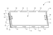
도 1은 본 발명의 하나의 실시예에 따른 바닥 패널(floor panel)의 상부 사시도이다.
도 2는 도 1의 바닥 패널의 하부 사시도이다.
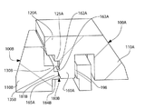
도 2A는 도 1의 바닥 패널의 근위 단부(proximal end portion)의 하부 사시도이다.
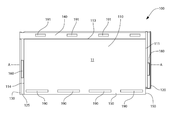
도 3은 도 1의 바닥 패널의 상면도이다.
도 4는 도 1의 바닥 패널의 하부도이다.
도 5는 도 3의 V-V에 따라 본 도 1의 단면도이다.
도 6은 본 발명의 실시예에 따른 스냅핏 어셈블리(snap-fit assembly) 사용하여 함께 수직하게 고정되는 도 1의 제 1 및 제 2 바닥 패널의 사시도이다.
도 7은 도 1의 바닥 패널 중 제 2 바닥 패널의 잠금 슬롯(locking slot)이 들어가는 도 1의 바닥 패널 중 제 1 바닥 패널의 잠금 부재(locking member)의 단면도이다.
도 8은 바닥 패널들을 수직하게 잠기게 위해서 도 1의 도 1의 바닥 패널 중 제 2 바닥 패널의 잠금 슬롯 내에 배치된 도 1의 바닥 패널 중 제 1 바닥 패널의 잠금 부재의 단면도이다.
도 9는 추가적인 세부사항을 도시하는 도 1의 바닥 패널의 단면도이다.The present invention can be more clearly understood from the accompanying drawings and the detailed description of the invention.
1 is a top perspective view of a floor panel according to one embodiment of the present invention.
Figure 2 is a bottom perspective view of the bottom panel of Figure 1;
Figure 2A is a bottom perspective view of the proximal end portion of the bottom panel of Figure 1;
Figure 3 is a top view of the floor panel of Figure 1;
Figure 4 is a bottom view of the floor panel of Figure 1;
5 is a cross-sectional view of FIG. 1 according to VV of FIG.
Figure 6 is a perspective view of the first and second floor panels of Figure 1 vertically secured together using a snap-fit assembly in accordance with an embodiment of the present invention.
Figure 7 is a cross-sectional view of the locking member of the first floor panel of the floor panel of Figure 1 into which the locking slot of the second floor panel of the floor panel of Figure 1 is inserted.
Fig. 8 is a cross-sectional view of the locking member of the first floor panel of the floor panel of Fig. 1 disposed in the lock slot of the second floor panel of the floor panel of Fig. 1 of Fig. 1 for vertically locking the floor panels.
Figure 9 is a cross-sectional view of the floor panel of Figure 1 showing further details.
이하에 설명될 선호된 실시예(들)은 사실상 단지 예시에 지나지 않으며 본 발명, 본 발명의 활용 또는 용도를 제한하는 것이 아니다. 본 발명의 원리에 따른 예시적인 실시예들의 설명은 전체 설명의 일부로 여겨지는 첨부된 도면과 함께 이해되도록 의도된다. 게다가, 본 발명의 특징 및 원리는 예시된 실시에들을 참조하여 설명된다. 따라서, 본 발명은 하나의 특징 또는 특징들의 조합으로 존재할 수 있는 일부 가능한 비-제한적인 조합들을 도시하는 예시적인 실시예들로 표현적으로 제한되지 않는다; 본 발명의 범위는 첨부된 청구항들에 의해서 정의된다.The preferred embodiment (s) described below are merely exemplary in nature and are not intended to limit the invention, its application, or uses. The description of exemplary embodiments in accordance with the principles of the present invention is intended to be understood with reference to the accompanying drawings, which are considered to be part of the description. In addition, the features and principles of the present invention are described with reference to the illustrated embodiments. Accordingly, the present invention is not to be limited expressly by the exemplary embodiments that illustrate some possible non-limiting combinations that may exist as a single feature or combination of features; The scope of the invention is defined by the appended claims.
먼저 도1 내지 4를 참조하면, 본 발명의 실시예에 따른 바닥 패널(100)이 도시된다. 한 실시예에서, 바닥 패널(100)은 비닐 타일(vinyl tile)일 수 있으며, 상기 비닐 타일은 본 명세서에 참조로 포함된 2010/9/30 발행된 미국특허 제2010/0247834에 개시된 구성 및 합판 구조를 구비한다. 하지만, 미국특허 제 2010/0245834에 개시된 비닐 타일과 달리, 바닥 패널(100)은 플로팅 바닥(floating floor)을 형성하기 위해서 인접한 바닥 패널(100)을 서로 맞물리게 하는 기계적 잠금 시스템을 포함한다. 추가적으로, 독창적인 패널(100)이 본 명세서에 "바닥 패널(floor panel)"로 언급되지만, 독창적인 바닥 패널(100)은 벽면(wall surface)과 같은 다른 표면을 덮기 위해서 사용될 수 있다.Referring first to Figures 1-4, a
바닥 패널(100)은 통상적으로 상부면(10) 및 반대편에 있는 하부면(11)을 포함한다. 상부면(10)은 바닥 패널(100)이 설치될 때 보일 수 있도록 설계되며, 그리하여 보이는 장식문양을 포함하는 마감된 표면일 수 있다. 반대로, 하부면(11)은 보조-바닥(sub-floor)의 상부면과 같은 덮여지는 표면과 접촉하도록 설계된다. 본 명세서에서 사용되는 "보조-바닥(sub-floor)"은 제한 없이 합판, 존재하는 타일, 시멘트 보드, 콘크리트, 벽면들, 하드우드 플랭크(hardwood plank), 및 이들의 조합을 포함하는 바닥 패널(100)에 의해서 덮이는 어떠한 표면을 포함하도록 의도된다. 그리하여, 어떤 실시예들에서, 하부면(11)은 마감되지 않은 표면일 수 있다.The
바닥 패널(100)은 종방향 축(A-A)을 따라 연장한다. 예시된 실시예에서, 바닥 패널(100)은 직사각형이다. 하지만, 본 발명의 다른 실시예들에서, 바닥 패널(100)은 다른 다각형을 취할 수 있다. 바닥 패널(100)은 종방향 축(A-A)을 가로지르는 방향에서 측정된 패널 폭 및 종방향 축(A-A)을 따라 측정된 패널 길이를 구비한다. 이러한 일부 실시예들에서(예시된 것과 같은), 바닥 패널(100)은 패널 길이가 패널 폭보다 큰 종방향으로 연장된 패널이다. 하지만, 다른 실시예들에서, 바닥 패널(100)은 패널 길이와 패널 폭이 실질적으로 같은 정사각형 패널일 수 있다.The
바닥 패널(100)은 통상적으로 패널몸체(panel body)(110), 상기 패널몸체(110)로부터 연장하는 제 1 플랜지(flange)(120), 및 패널몸체(110)로부터 연장하는 제 2 플랜지(130)를 포함한다. 예시된 실시예에서, 바닥 패널(100)의 디스플레이 표면으로 고려된 상부면(10) 때문에, 제 1 플랜지(120)는 상부 플랜지로 고려될 수 있는 반면, 제 2 플랜지(130)는 하부 플랜지로 고려될 수 있다. 하지만, 다른 실시예에서, 바닥 패널(100)은 제 2 플랜지(130)가 바닥 패널(100)의 상부면(10)의 일부를 형성하는 상부 플랜지인 반면, 제 1 플랜지(120)가 하부면(11)의 일부를 형성하는 하부 플랜지가 되도록 설계될 수 있다.The
일부 실시예들에서, 바닥 패널(100)은 제 3 플랜지(140) 및 제 4 플랜지(150)를 더 포함한다. 예시된 실시예에서, 상부면(10)은 바닥 패널(100)의 디스플레이 표면으로 고려되기 때문에, 제 4 플랜지(150)는 또한 상부 플랜지로 고려될 수 있는 반면, 제 2 플랜지(130)는 하부 플랜지로 고려될 수 있다. 하지만, 다른 실시예에서, 바닥 패널(100)은 제 3 플랜지가 바닥 패널(100)의 상부면(10)의 일부를 형성하는 상부 플랜지이며 제 4 플랜지가 하부면(11)의 일부를 형성하는 하부 플랜지가 되도록 설계될 수 있다. In some embodiments, the
예시된 실시예에서, 제 4 플랜지(150)는 도시된 것처럼 패널몸체(110)의 두 개의 인접한 모서리에 대하여 L형 플랜지를 집합적으로 형성하기 위해서 제 1 플랜지(120)와 통합되어 형성되고 연결된다. 유사하게, 제 4 플랜지(150)는 도시된 것처럼 패널몸체(110)의 남아있는 두 개의 인접한 모서리에 대하여 L형 플랜지를 통합적으로 집합적으로 형성하기 위해서 제 2 플랜지(130)와 통합되어 형성되고 연결된다.In the illustrated embodiment, the
제 1 플랜지(120)는 패널몸체(110)의 제 1 모서리(111)로부터 연장하는 반면, 제 2 플랜지(130)는 제 1 모서리의 반대편에 있는 패널몸체(110)의 제 2 모서리(112)로부터 연장한다. 유사하게, 제 3 플랜지(140)는 패널몸체(110)의 제 3 모서리(113)로부터 연장하는 반면, 제 4 플랜지(150)는 제 3 모서리(113)의 반대편에 있는 패널몸체(110)의 제 4 모서리(114)로부터 연장한다. 예시된 실시예에서, 제 1 모서리(111)는 패널몸체(110)의 근위 모서리인 반면, 제 2 모서리(112)는 패널몸체(110)의 원위 모서리(distal edge)이며, 종방향 축(A-A)은 제 1 및 2 모서리(111, 112)(제 1 및 2 플랜지(120, 130))로부터 연장한다. 하지만, 제 3 및 4 모서리는 패널몸체(110)의 제 1 및 2 측면 모서리를 각각 형성한다.The
예시된 실시예에서, 각각의 제 1, 2, 3 및 4 플랜지(120, 130, 140, 150)는 실질적으로 전체 모서리(111-114)를 따라 연장하는 연속 플랜지이다. 하지만, 다른 실시예에서, 제1, 2, 3 및 4 플랜지(120, 130, 140, 150) 중 하나 이상은 간격으로 분리되며 집합적으로 플랜지를 형성하는 복수의 플랜지 세그먼트(segment)를 포함하기 위해서 불연속일 수 있다.In the illustrated embodiment, each of the first, second, third and fourth flanges 120,130, 140,150 is a continuous flange extending substantially along the entire edge 111-114. However, in other embodiments, at least one of the first, second, third, and
복수의 바닥 패널(100)이 설치되는 동안에(도 6 및 9a-9d에 도시) 바닥 패널들(100)의 열을 형성하기 위해서 끝에서 끝으로(근위에서 원위까지) 배열될 때, 제 1 및 2 플랜지(120, 130)는 바닥 패널들(100) 사이에 수직 분리를 막기 위해서 다른 하나와 스냅핏 잠금 어셈블리(snap-fit locking assembly)를 사용하여(이하에 자세히 설명됨) 기계적으로 서로 맞물리고 겹치게 하도록, 제 1 및 2 플랜지(120, 130)가 구비된다. 복수의 바닥 패널(100)이 설치되는 동안에(도 6 및 9a-9d에 도시) 바닥 패널들(100)의 인접한 열들(rows)을 형성하기 위해서 측면으로 인접하여(옆에서 옆으로) 배열될 때, 제 3 및 4 플랜지(140, 150)는 제 1 수평 방향에 실질적으로 수직한 제 2 수평 방향 사이에서 미끄러지는 동안 제 1 수평 방향에서 바닥 패널(100) 사이에 수평 분리를 막기 위해서 톱니/톱니 슬롯 결합(thooth/thooth slot mating)을 사용하여 기계적으로 서로 맞물리고 겹치게 하도록, 제 3 및 4 플랜지(140, 150)를 구비한다.When arranged from end to end (from proximal to distal) to form rows of
이하에서 더 자세히 설명된 것처럼, 다른 실시예들에서, 스냅핏 잠금 어셈블리는 인접한 열들의 바닥 패널(100)을 함께 수직하게 잠그기 위한 스냅핏 잠금 어셈블리를 사용하여 인접한 열들의 바닥 패널(100)을 기계적으로 서로 맞물리게 하기 위해 패널몸체(110)의 제 1 및 2 측면 모서리를 따라(상기 모서리에 추가로 또는 대신에, 근위 및 원위 모서리를 따라) 구비될 수 있다. 상기 실시예에서, 제 1 및 2 측면 모서리(즉, 제 3 및 4 모서리(113, 114))로부터 연장하는 플랜지들은 제 1 및 2 플랜지(120, 130)에 고려될 수 있다.As described in more detail below, in other embodiments, the snap fit lock assembly is configured to mechanically lock the
상기했듯이, 바닥 패널(100)은 바닥 패널들(100)을 이용하여 플로팅 바닥(floating floor)의 설치 동안에 인접한 바닥 패널들(100)을 함께 수직하게 잠그기 위한 스냅핏 잠금 어셈블리를 포함한다. 본 명세서에 사용되는, "수직의/수직하게(vertical)"는 바닥 패널(100)의 상부면(10)의 평면에 실질적으로 수직한 방향을 말한다. "제 1 수평 방향"은 종방향 축에 실질적으로 평행한 방향을 말한다. "제 2 수평 방향"은 바닥 패널(100)의 상부면(10)의 평면 및 종방향 축에 실질적으로 수직한 방향을 말한다.As discussed above, the
도 2, 2a 및 5를 참조하여, 바닥 패널(100)의 스냅핏 잠금 어셈블리를 더 자세히 설명할 것이다. 스냅핏 잠금 어셈블리는 통상적으로 제 1 플랜지(120)로부터 돌출하는 잠금 부재(160), 및 이하에서 설명될 바닥 패널들(100) 중 인접한 하나의 잠금 부재(160)를 수용하기 위한 제 2 플랜지(130)에 형성된 잠금 슬롯(180)을 포함한다. 예시된 실시예에서, 잠금 부재(160)는 제 1 플랜지(120)와 통합적으로 형성된다. 하지만, 다른 실시예들에서, 잠금 부재(160)는 제 1 플랜지(120)에 나중에 고정되는 분리된 부품일 수 있다.Referring to Figures 2, 2a and 5, the snap fit lock assembly of the
지금 부재(160)는 제 1 플랜지의 제 1 표면(121)으로부터 돌출한다. 잠금 부재(160)는 통상적으로 언더컷 표면(undercut surface)(162) 및 잠금몸체(locking body)(161)를 포함한다. 잠금 홈(166)은 언더컷 표면(162) 및 제 1 플랜지(120) 사이에 형성된다. 예시된 실시예에서, 언더컷 표면(162)은 잠금몸체(161)의 측면(164)로부터 돌출하는 잠금 립(locking lip)(163)에 의해서 형성된다. 보다 구체적으로, 잠금 립(163)은 패널몸체(110)로부터 떨어진 방향에서 잠금몸체(161)의 측면(164)으로부터 돌출한다. 다른 실시예에서, 잠금 립(163)은 패널몸체(110) 쪽의 방향에서 잠금몸체(161)의 측면(168)로부터 돌출할 수 있다.The
도시되었듯이, 잠금 립(163)의 선단(lead end)은 바닥 패널들(100)을 사용하는 바닥의 설치 동안에 잠금 슬롯(180) 안에 잠금 부재(160)의 진입을 쉽게 하기 위해서 면취된 표면(chamfered surface)(165)을 포함한다. 이하에 더 자세히 설명되었듯이, 인접한 바닥 패널들(100)이 스냅핏 잠금 어셈블리를 사용하여 함께 결합될 때, 면취된 표면(165)은 정상 상태(normal state)(도 5에 도시)에서 편향된 상태(deflected state)(미도시)로 (탄성 있는)잠금 부재(160)를 굽히기 위한 잠금 슬롯(180)을 정의하는 제 2 플랜지(130)의 월(wall)(181)과 상호작용한다. 한 실시예에서, 면취된 표면(165)은 수직한 방향으로부터 5°내지 15°의 범위에 있다. 잠금 부재(160)가 바닥 패널들(100) 중 인접한 하나의 바닥 패널의 잠금 슬롯(180)에 완전히 삽입될 때, 인접한 바닥 패널의 월(181)은 잠금 홈(166)(도 8 도시)에 끼워 진다.As shown, the lead end of the locking
언더컷 표면(162)은 예시된 실시예에서 잠금 립(163)에 설치되는 반면, 다른 실시예에서는 언더컷 표면(162)은 잠금몸체(161) 내에 직접적으로 형성된다. 상기 실시예에서, 잠금 슬롯(180)의 월(181)은 언더컷 표면(162)과 결합하여 연장하는 잠금 슬롯(180)에서 돌출하는 잠금 립 자체를 포함할 수 있다.The undercut
언더컷 표면(162)은 실질적으로 패널몸체(110)의 상부면(111)과 평행하다(패널몸체(110)의 상부면(111)은 바닥 패널(100)의 상부면(10)의 일부를 형성한다). 다른 실시예에서, 언더컷 표면(162)은 패널몸체(110)의 상부면(111)에 대하여 기울어져있다. 잠금 부재의 반대편에, 간극(167)이 잠금몸체(161) 및 패널몸체(110) 사이에 존재한다. 이하에 더 자세히 설명되었듯이, 상기 간극(167)은 인접한 바닥 패널들(100)의 수평적인 잠금을 제공하는 리세스(135)를 정의하는 제 2 플랜지(130)의 높은 월(182)을 수용하기 위한 공간을 제공한다. 잠금 부제는 길이(LLM)을 가진다. 잠금 슬롯은 길이(LTS)를 가진다. 예시된 실시예에서, LLM은 LTS보다 짧다. 특정한 실시예에서, LTS는 1.2 LLM과 동일하거나 크다. 상기 특징은 잠금 부재(160)가 정밀성이 요구됨 없이 바닥의 설치 동안에 잠금 슬롯(180) 안으로 삽입되도록 한다. 상기 특징이, 직선 "누름(push down)"에 더하여, 잠금 부재(160)가 잠금 슬롯(180) 안으로 접혀 들어가도록 한다. 잠금 부재(160)의 스냅핏 잠금 어셈블리 및 잠금 슬롯은 인접한 열들의 바닥 패널들 사이에 수직의 잠금을 달성하기 위해서 패널몸체의 측면 모서리(113, 114)를 따라 이용되는 실시예들에서, LTS가 LLM보다 큰 구성은 정확한 절단의 필요성을 최소화 하는 상대적 미끄럼(relative sliding)을 허용한다. 이러한 실시예에서, LTS는 1.5 LLM과 동일하거나 크다.The undercut
잠금 슬롯(180)은 제 2 플랜지(130)를 통과하는 통로를 형성한다는 점에서 예시된 실시예에서 관통-슬롯(through-slot)이다. 하지만, 다른 실시예에서, 잠금 슬롯(180)은 관통-슬롯이 아닐 수 있으며, 바닥과 침하될 수 있다. 상기했듯이, 제 2 플랜지(130)가 설치될 바닥 상에서 잠금 슬롯(180)이 보일 수 있도록 제거되어 제 2 플랜지가 바닥 패널(100)의 상부 플랜지일 때, 상기 실시예는 매우 유용하다. 상기했듯이, 잠금 슬롯(180)이 관통-슬롯이 아닌 실시예에서, 잠금 립은 잠금 부재(160)의 언더컷 표면(162)와 결합하기 위해 잠금 슬롯(180)의 내부 월로부터 잠금 슬롯(180) 안으로 돌출하도록 구비될 수 있다. 대안적으로, 홈이 잠금 부재의 잠금 립(163)을 수용하기 위해 잠금 슬롯(180)의 내부 월에 구비될 수 있다.The
잠금 슬롯은 월(181)에 의해서 정의된다. 게다가, 제 2 플랜지(130)는 잠금 슬롯(180)의 모서리에 인접한 잠금 표면(184)을 포함한다. 이하에서 더 자세히 설명되었듯이, 인접한 바닥 패널(100)의 잠금 부재(160)가 잠금 슬롯(180)에 완전히 삽입될 때, 잠금 부재(160)의 언더컷 표면(162) 및 지금 표면(184) 사이의 기계적 상호작용이 바닥 패널을 함께 수직하게 잠근다. 잠금 표면(184)은 패널몸체(110)의 하부면(112)으로부터 수직하게 떨어진다(패널몸체의 하부면(112)은 바닥 패널(100)의 하부면(11)의 일부를 형성한다). 상기 특징이 잠금 부재(160)가 패널몸체(110)의 하부면(112)에 의해서 형성된 평면 넘어서 돌출되지 않고 언더컷 표면(162)이 잠금 표면(142)과 기계적으로 결합하도록 하는 방식으로 잠금 부재(160)가 완전히 끼워 지도록 한다. 추가적으로, 잠금 표면(184)이 예시된 실시예에서 잠금 슬롯(180) 및 패널몸체(110)의 제 2 모서리(112) 사이에 위치되는 반면, 다른 실시예에서 잠금 표면(184)은 잠금 슬롯에 인접한 다른 위치에 위치될 수 있다.The lock slot is defined by
게다가, 제2 플랜지(130)는 패널몸체(110)의 하부면(112)에 실질적으로 동일한 표면에 있는 잠금 슬롯(180)의 반대편에 하부면(131)을 구비한다. 이것이 수직한 하중을 경험하게 될 때 제 2 플랜지(130)의 버팀부(strut portion)(132)가 바닥의 설치 후 변형되지 않도록 도와준다. 그 결과, 시간에 따른 수직 잠금의 탄성이 더 향상된다.The
예시된 것처럼, 잠금 부재(160)는 긴(elongated) 직사각형 부재이며, 잠금 슬롯(180) 또는 긴 직사각형 슬롯이다. 하지만, 다른 실시예에서, 잠금 부재(160) 및 잠금 슬롯(180)은 정사각형, 다각형, 타원, 또는 원형과 같은 다른 형상들을 취할 수 있다. 예컨대, 이러한 하나의 실시예에서, 잠금 부재(160)는 원통형 요소일 수 있다. 즉, 잠금 부재(160) 및 잠금 슬롯(180)은 수직의 잠금 기능을 달성할 수 있는 한 어떠한 형태일 수 있다.As illustrated, locking
도 1 내지 2 및 5를 참조하면, 제 1 플랜지(120)는 돌기(protuberance)(125)를 구비하는 반면, 제 2 플랜지(130)는 상응하는 리세스(recess)(135)가 구비된다. 리세스(135)는 적어도 제 1 수평 방향에서 인접한 바닥 패널들(100) 사이에서 수평 잠금(horizontal locking)을 제공하기 위해서 돌기(125)를 수용하도록 형상화 및 크기화된다. 보다 구체적으로, 바닥 패널들(100) 중 하나의 돌기(125)는 바닥 패널(100)의 다른 하나의 리세스(135) 안으로 삽입될 때, 바닥 패널들(100)은 하나의 바닥 패널(100)의 돌기(125) 및 다른 바닥 패널(100)의 리세스(135)의 월(182) 사이에서 기계적 상호작용을 통하여 함께 수평하게 잠기게 된다(도 8에 도시).1 to 2 and 5, the
예시된 실시예에서, 돌기(125)는 긴 리지(ridge)의 형태인 반면, 리세스(135)는 상응하는 긴 채널(channel)의 형태이다. "접이식 단계(fold-down step)"를 고려할 수 있는 긴 리지는 바닥 패널(100)의 제 1 플랜지(120)의 폭 일부 또는 전부를 가로질러 연장할 수 있다. 유사하게, "접이식 슬롯(fold-down slot)"을 고려할 수 있는 긴 리지는 바닥 패널(100)의 제 2 플랜지(130)의 폭 일부 또는 전부를 가로질러 연장할 수 있다.In the illustrated embodiment, the
다른 실시예에서, 돌기(125) 및 리세스(135)는 적어도 제 1 수평 방향에 바람직한 수평 잠금을 제공하도록 다른 하나와 짝을 맞출 수 있는 다른 형태들을 취할 수 있다. 예시된 실시예에서, 잠금 슬롯(180)은 리세스(135)의 바닥(136)에 위치되며 잠금 부재(160)는 돌기(125)에 위치된다. 보다 구체적으로, 잠금 부재(160)는 돌기(125)의 원위 표면(126)으로부터 아래쪽으로 돌출된다. 다른 실시예에서, 잠금 부재(160) 및 돌기(125)는 서로 독립될 수 있으며 잠금 슬롯(180) 및 리세스(135) 또한 서로 독립될 수 있다. In other embodiments, the
다시 도 1을 참조하면, 바닥 패널(100)은 패널몸체(110)의 제 4 모서리(114)에 위치된 홈(75)을 더 포함할 수 있다(또한, 도 2에 도시). 상기 홈(75)은 연속적인 방법으로 바닥 패널(100)의 전체 길이를 연장한다. 대안적으로, 상기 홈은 바닥 패널(100)의 길이의 일부를 연장하거나 분할될 수 있다. 추가적으로, 바닥 패널(100)은 또한 제 3 플랜지(140)의 자유 측면 모서리(145)로부터 연장하는 상보적인 돌출부(complimentary projection)(85)를 포함한다. 돌출부(85)는 연속적인 방법으로 바닥 패널(100)의 전체 길이를 연장한다. 대안적으로, 상기 돌출부는 바닥 패널의 길이의 일부를 연장하거나 분할될 수 있다. 이하에서 더 자세히 설명되었듯이, 바닥 패널(100)의 돌출부(85)는 접이식 수직의 잠금 단계 동안에 인접한 열에서 바닥 패널(100)의 홈(75) 안으로 삽입된다.Referring again to FIG. 1, the
도 6-8을 참조하여, 열에서 두 개의 종방향의 인접한 바닥 패널(100)의 수직 잠금(vertical locking)이 설명될 것이다. 도면번호 및 논의를 쉽게 하기 위해서, 이러한 바닥 패널들(100)은 제 1 바닥 패널(100A) 및 제 2 바닥 패널(100B)로 숫자로 식별된다. 바닥 패널들(100A, 100B)는 상기된 바닥 패널(100)과 동일하다(그리고 상기 바닥 패널들은 서로 동일하다). 그리하여, 숫자들은 제 1 바닥 패널(100A)을 위해 접미사 "A" 및 제 2 바닥 패널(100B)을 위해 접미사 "B"를 붙인 요소들로 언급된다.6-8, vertical locking of two longitudinal
도 6을 참조하면, 제 2 바닥 패널(100B)은 덮여 지는 표면 상의 바람직한 위치에 위치된다. 일단 적절히 위치되면, 제 1 바닥 패널(100A)은 제 2 바닥 패널(100B)에 인접하게 위치되어서, 제 1 바닥 패널(100A)의 제 1 플랜지(120A)는 제 2 바닥 패널(100B)의 제 2 플랜지(130) 위에 가로놓인다. 접이식(fold-down) 방식을 이용할 때(도 6에 도시), 그러면 제 1 바닥 패널(100A)는 종방향 축(A-A)에 대하여 기울어지며 제 1 바닥 패널(100A)의 돌기(125)의 단부가 제 2 바닥 패널(100B)의 리세스(135B)에 삽입될 때까지 내려간다. 바닥 패널들(100)의 이전 열이 설치되는 곳에서, 또한 상기 단계는 제 2 패널(100B)에 위치되어 있는 열에서 인접한 패널들 중 하나의 열에 바닥 패널들 중 하나의 홈(75) 안으로 제 1 바닥 패널(100A)의 돌출부(85)가 삽입되는 단계를 포함할 수 있다(도 1 및 9c-d에 도시).Referring to Fig. 6, the
제 1 바닥 패널(100A)의 올려진 측면 모서리는 내려가며, 돌기(125A)의 길이부가 점점 리세스(135B) 안으로 삽입된다. 제 2 바닥 패널의 리세스(135B)를 정의하는 월들(182B) 및 제 1 바닥 패널(100A)의 돌기(125A) 사이에서 기계적인 상호작용/접촉(즉, 기계적 개입 또는 교대)의 결과로써, 제 1 및 2 패널(100A, 100B)이 제 1 수평 방향에서 함께 수평하게 잠긴다.The raised side edge of the
도 7을 참조하면, 잠금 부재(160A)의 선단이 잠금 슬롯(180B)을 넣기 시작할 때까지, 상기-설명된 내림(lowering)이 일어난다. 이때, 잠금 부재(160A)의 잠금 립(163A)의 면취된 표면(165A)은 잠금 슬롯(180B)을 정의하는 월(181B)와 접촉한다. 아래쪽으로 힘이 계속 가해짐에 따라, 힘이 정상 상태(도 7)에서 편향된 상태(미도시)로 잠금 부재(160A)를 이동시키는 잠금 부재(B)에 가해진다. 도시된 실시예에서, 잠금 부재(160)는 잠금 립(163A)이 잠금 슬롯(180)을 완전히 넣도록 하기 위해서 편향 간극(deflection gap)(198) 안으로 편향시킬 것이다. 상기했듯이, 잠금 부재(160A)는 탄성이 있어, 상기 삽입 동안에 월(181B)에 대하여 잠금 립(163A)에 압력을 가하도록 계속해서 스스로를 편향시킨다.Referring to FIG. 7, the above-described lowering occurs until the tip of the
도 8을 참조하면, 관통 슬롯(180B) 안으로 잠금 부재(160A)의 아래쪽으로 삽입은 언더컷 표면(162A) 잠금 표면(184)과 정렬될 때까지 계속된다. 잠금 슬롯(180) 이 관통 슬롯인 실시예에서, 상기 현상은 언더컷 표면이 들어가는 반대편 상의 잠금 슬롯(180)을 내보낼 때 발생한다. 이때, 잠금 부재(160)는 스스로 편향되기 때문에, 잠금 부재(160A)는 언더컷 표면(162A)이 잠금 표면(184B)과 접촉하는 정상 상태로 자동적으로 돌아간다. 언더컷 표면(162A) 및 잠금 표면(184B) 사이의 기계적 상호작용의 결과로, 제 1 및 2 바닥 패널(100A, 100B)은 서로 수직하게 잠긴다. 이 상태에서 알 수 있듯이, 잠금 슬롯(180B)를 정의하는 월(181B)은 제 1 패널(100A)의 잠금 홈(166) 안으로 끼워 진다(도 5).Referring to FIG. 8, the downward insertion of the locking
게다가, 잠금 부재(160)가 정상 상태로 돌아가 후 존재하는 편향 간극(198)에도 불구하고, 제 1 및 2 바닥 패널(100A, 100B)은 제 1 바닥 패널(100A)의 돌기(125A) 및 제 2 바닥 패널(100B)의 리세스(135B)의 월(182B) 사이의 계속된 기계적 상호작용 때문에 수평하게 잠긴다. 그리하여, 잠금 부재(160A)는 깨짐 또는 추가적인 변형 없이 잠금 슬롯(180B)의 밖으로 뺄 수 없다. 추가적으로, 잠금 슬롯(180B)를 넣는 잠금 부재(160) 이전에 돌기(125A) 및 리세스(135B)에 의해 달성된 수평 잠금이 제 1 및 2 바닥 패널(100A, 100B)의 상대적 위치들을 유지하는데 도움을 주며, 잠금 부재(160A)의 편향이 유발된다.In addition, the first and
예시된 실시예에서 잠금 부재(160A)의 폭은 잠금 슬롯(180B)의 폭보다 약간 작아서 편향 간극(198)이 존재(그리고, 잠금 부재(160A)가 푠향된다)하는 반면, 다른 실시예에서 잠금 부재(160A) 및 잠금 슬롯(180B)의 폭은 실질적으로 동일할 수 있다(작은 오차를 제외한다). 이러한 실시예에서, 잠금 립(163A)은 잠금 탭(160A)이 바람직한 수직 잠금을 달성하기 위한 잠금 슬롯(180B)을 완전히 넣도록 스스로 편향되거나 압축될 수 있다. 이러한 실시예에서, 상기 잠금 립(163A)의 편향 또는 압축은 잠금 부재(160A)의 편향된 상태로 고려될 수 있다. 여전히 다른 실시예에서, 스냅핏 잠금 어셈블리의 탄성 작용은 제 2 플랜지(130B)의 버팀부(132B)의 편향에 의해서 전체적으로 또는 부분적으로 일어날 수 있다.In the illustrated embodiment, the width of the locking
예시되었듯이, 잠금 부재(160A)는 일단 잠금 부재가 잠금 슬롯(180B)를 통과하면 장소에 스냅되며 삽입되는 동안에 편향되는 탄성력을 가지도록 설계된다. 하지만, 잠금 부재(160A)를 구비하는 것에 추가로 또는 대안으로, 압축 가능한 물질과 같은 부드러운 물질이 잠금 부재(160)를 형성하도록 사용될 수 있다. 이것이 탄성적 편향에 추가로 또는 대신하여 잠금 부재(160A)를 압축함으로써 수직 잠금 작용을 가능하게 한다. 부드러운 층 또는 층들이 더 많은 가소제, 부드러운 공중합체, 고 바인더/필러 비, 및 다른 종류의 수지들을 사용하여 달성될 수 있다.As illustrated, the locking
제 1 및 2 바닥 패널(100A, 100B)의 수직 잠금이 상기 접이식 방법을 사용하여 설명된 반면, 수직의 누름(push-down) 방식 또한 사용될 수 있다. 게다가, 스냅핏 수직 잠금 어셈블리(즉, 잠금 부재(160) 및 잠금 슬롯(180))은 긴면(측면) 또는 짧은면(원위 단부 또는 근위 단부) 둘 중 하나에 포함될 수 있다. 상기된 스냅핏 어셈블리는 설치 후 튀어 오르거나 쉽게 풀리거나 수직 이동 또는 가 존재하지 않는다. 게다가, 오직 하나의 잠금 부재(160) 및 잠금 슬롯(180)이 예시되었지만, 다른 실시예들에서, 스냅핏 잠금 어셈블리는 반대편 플랜지들에 상응하는 패턴들로 배열된 다수의 잠금 부재(160) 및 다수의 잠금 슬롯(180)을 포함하여 결합을 유발될 수 있다. 일부 실시예에서, 바닥 패널(100)은 탄성 바닥 패널이다. 이러한 실시예 중 하나는, 바닥 패널(100)은 열가소성, 즉, 비닐, 썰린(surlyn), 및 PVC로 만들어 질 수 있다.While vertical locking of the first and
상기했듯이, 잠금 부재(160)는 수직 잠금을 유발하기 위한 잠금 슬롯(180)에 인접한 잠금 표면(184)과 기계적으로 협력하여, 렛지(ledge)를 최소화한다. 추가로, 수평 잠금을 유발하기 위한 돌기(125) 및 리세스(135)의 기계적 상호작용은 간극이 생기는 것을 막는다.As mentioned above, the locking
도 1 및 도 2를 참조하면, 바닥 패널(100)은 제 3 플랜지(130)로부터 돌출하는 복수의 톱니(theeth)(191) 및 제 4 플랜지(150) 안에 형성된 복수의 톱니 슬롯(tooth slot)(190)을 포함한다. 톱니 슬롯들(190)은 종방향 축(A-A)에 실질적으로 평행한 축을 따라 서로 동일한 간격을 갖는다. 예시된 실시예에서, 각각의 톱니 슬롯(190)은 긴 슬롯(elongated slot)이다.1 and 2, the
복수의 톱니(191)는 서로 떨어져 있다. 톱니(191) 및 톱니 슬롯은 서로에게 상응하는 패턴으로 바닥 패널(100)에 배열되어서, 두 개의 바닥 패널(100)이 서로 인접하게 측방향으로 위치될 때, 바닥 패널(100)은 측방향으로 인접한 바닥 패널들(100)의 톱니(191)를 다른 바닥 패널(100)의 톱니 슬롯(190)으로 삽입함으로써 서로 맞물려질 수 있다. 두 개의 측방향으로 인접한 바닥 패널들(100)이 하나의 바닥 패널(100)의 톱니(191)를 다른 바닥 패널(100)의 톱니 슬롯(190)으로 삽입함으로써 서로 맞물려질 때, 톱니(191) 및 톱니 슬롯(190) 사이의 기계적 상호작용은 수평방향으로 하중이 가해지는 힘을 받을 때 제 2 수평 방향에서 바닥 패널들(100) 사이의 상대적 움직임을 막는다.The plurality of
게다가, 각각의 톱니 슬롯(190)의 길이는 각각의 톱니(191)의 길이보다 길게 설계되었기 때문에, 측방향으로 인접한 제 1 및 2 패널들(100A, 100B)은 제 2 수평 방향에서 수평적으로 고정되면서 제 1 수평 방향에서 서로에 대하여 미끄러질 수 있다. 한 실시예에서, 톱니(191)의 길이는 톱니 슬롯(190)의 길이의 1.5배 이다. 톱니(191) 및 톱니 슬롯(190)을 위한 적합한 디자인의 실시예에 관한 세부사항은 본 명세서에서 참조로써 통합된 2013/2/23에 출원된 특허문헌 PCT/US13/27675에 개시되어있다.In addition, since the length of each
상기된 스냅핏 잠금 어셈블리는 바닥 패널(100)의 전체 두께의 사용을 더 좋게 하고 효과적이며, 따라서, 잠금 부재(160), 톱니(191), 톱니 슬롯(190) 및 잠금 슬롯(180)이 바닥 패널(100)에 통합적으로 형성되도록 한다.The snap fit lock assembly described above makes the use of the overall thickness of the
도 9를 참조하여, 바닥 패널(100)의 추가적 세부사항을 설명할 것이다. 상기 세부사항은 도 1-8의 복잡성 및 어수선함을 막기 위해 도 1-8에서 생략되었다. 도 10에 도시되었듯이, 바닥 패널(100)은 상부층(280) 및 하부층(281)을 포함하는 적층 구조(laminate structure)일 수 있다. 각각의 상부층(280) 및 하부층(281)은 복수의 층을 포함할 수 있다. 이러한 실시예에서, 상부층(280)은 혼합층(mix layer), 보호층(wear layer), 및 상부 코트층(top coat layer)을 포함할 수 있다. 게다가, 다른 살시예에서, 바닥 패널(100)은 상부층(280) 및 하부층(281)에 추가로, 중간 유리섬유(intermediate fiberglass) 또는 폴리에스터 스크림층(polyester scrim layer)과 같은 층들을 포함할 수 있다. 추가된 층들은 또한 하나 이상의 향균층(antimicrobial layer), 방음층(sound deadening layer), 쿠션층(cushioning layer), 미끄럼 방지층(slide resistant layer), 경화층(stiffening layer), 통로층(channeling layer), 기계적으로 양각된 직물, 또는 화학 직물을 포함할 수 있다.With reference to Fig. 9, additional details of the
일부 실시예들에서, 바닥 패널(100)의 상부면(10)은 그 위에 적용된 보이는 장식용 패턴을 포함한다. 하나의 실시예에서, 상부층(280)은 플라스틱, 비닐, 폴리염화비닐, 폴리에스터, 또는 이들의 조합을 포함하는 신축성 시트(flexible sheet) 물질을 포함한다. 일부 실시예들에서, 하부층(280)은 플라스틱, 비닐, 폴리염화비닐, 폴리에스터, 폴리올레핀, 나일론 또는 이들의 조합을 포함하는 신축성 시트 물질을 포함한다.In some embodiments, the
하나의 실시예에서, 바닥 패널(100)의 패널몸체(110)는 2mm 내지 12mm 범위의 두께를 가진다. 다른 실시예에서, 바닥 패널(100)의 패널몸체(110)는 2mm 내지 5mm 범위의 두께를 가진다. 하나의 특수한 실시예에서, 바닥 패널(100)의 패널몸체(110)는 3mm 내지 4mm 범위의 두께를 가진다. 하나의 실시예에서, 바닥 패널(100)은 240MPA 내지 620MPA 범위의 영률을 가지도록 설계된다. 다른 실시예에서, 바닥 패널(100)은 320MPA 내지 540MPA 범위의 영률을 가지도록 설계된다.In one embodiment, the
예시된 실시예에서, 상부층(280)은 상부 혼합층(283) 꼭대기에 위치된 투명 필름층/보호층(282)을 포함한다. 예컨대, 상부 혼합층(283)은 플라스틱, 비닐, 폴리염화비닐, 폴리에스터, 또는 이들의 조합과 같은 실질적인 신축성 시트 물질로 형성될 수 있다. 보이는 장식 패턴은 상부층(280)의 상부면에 적용된다. 일부 실시예들에서, 투명 필름층/보호층(282)은 약 4-40mils(약 0.1-1mm), 바람직하게는 약 6-20mils(약 0.15-0.5mm), 및 보다 바람직하게는 약 12-20mils(약 0.3-0.5mm)의 두께를 가진다.In the illustrated embodiment, the
일부 실시예들에서, 상부층(280)은 약 34-110mils(약 0.8-2.8mm), 바람직하게는 약 37-100mils(약 0.9-2.5mm), 보다 바람직하게는 약 38-100(약 1.0-2.5mm)의 두께를 가질 수 있다.In some embodiments, the
도시된 실시예에서, 하부층(281)은 오직 하부 혼합층(bottom mix layer)을 포함한다. 예컨대, 하부 혼합층은 플라스틱, 비닐, 폴리염화비닐, 폴리에스터, 폴리올레핀, 나일로, 또는 이들의 조합을 포함하는 신축성 시트 물질로 형성될 수 있다. 다른 실시예에서, 상기 하부층(281)은 또한 후-산업화 스크랩 또는 후-사용 스크랩과 같은 재활용 물질을 포함할 수 있다.In the illustrated embodiment, the
일부 실시예들에서, 하부층(281)은 약 34-110mils(약 0.8-2.8mm), 바람직하게는 약 37-100mils(약 0.9-2.5mm), 보다 바람직하게는 약 38-100(약 1.0-2.5mm)의 두께를 가질 수 있다.In some embodiments, the
상부층(280)의 하부면은 접착제로 하부층(281)의 상부면에 적층된다. 예컨대, 상기 접착제는 핫 멜트 접착제(hot melt adhesive), 압력 감지 접착제(pressure sensitive adhesive), 또는 구조적 및/또는 반응성 접착제와 같은 어떠한 적절한 접착제일 수 있다. 예컨대 상기 접착제는 적어도 25 포스-파운드(force-pound), 보다 바람직하게는 화씨 145도에서 약 24시간 동안 가열된 후 약 4.3 N/mm의 접착력을 가질 수 있다. 도시된 실시예에서, 접착제는 실질적으로 하부층(12)이 상부면의 전체에 구비된다. 접착제는 예컨대 약 1-2mils(약 0.0254-00508mm)의 두께를 구비하도록 적용된다. 하지만, 본 기술 분야의 통상의 기술자들은 접착제의 두께는 상부층(280)의 하부면의 질감(texture) 및 하부층(281)의 상부면의 질감에 따라 변한다는 것이 이해되어야 할 것이며, 실질적으로 부드러운 표면이 더 좋은 접착 및 접착력이 있기 때문에 적은 적은 접착제를 필요로 한다.The lower surface of the
한 실시예에서, 기계적 상호결합 시스템(즉, 잠금 부재(160) 및 잠금 슬롯(180))에 의해서 가해지는 응력 때문에 상부층(280) 및 하부층(281) 사이에 전단 및/또는 갈라짐의 위험을 최소화하기 위해서, 기계적 상호결합 시스템은 동일하게 통합적으로 형성된 층(상부 혼합층 또는 하부 혼합층)에 의해서 형성된다. 예시된 실시예에서, 잠금 부재(160) 및 잠금 슬롯(180)은 상부층(280)(및 보다 바람직하게는 상부 혼합층)에 통합적으로 형성된다.In one embodiment, the risk of shearing and / or cracking between the
상부 및 하부 혼합층은 가소제, 충전제, 및 결합제로 만들어질 수 있으며 일부 실시예들을 위한 다음의 퍼센트로 만들어질 수 있다:The upper and lower mix layers can be made of plasticizers, fillers, and binders and can be made up of the following percentages for some embodiments:
- 하부 혼합층 및 상부 혼합층의 가소제 % 평균(투명필름(clear film) 없음): 6.4% 내지 8.1%의 범위-% plasticizer average (without clear film) in the lower and upper mixed layers: in the range of 6.4% to 8.1%
- 하부 혼합층 및 상부 혼합층의 필러 % 평균(투명필름(clear film) 없음): 65.9% 내지 78.7%의 범위-% filler average of the lower and upper mixed layers (without clear film): in the range of 65.9% to 78.7%
- 하부 혼합층 및 상부 혼합층의 바인더 % 평균(투명필름(clear film) 없음): 21.3% 내지 34.1%의 범위- Binder% average of the lower and upper mixed layers (without clear film): range of 21.3% to 34.1%
%비율을 바꿈으로써, 바닥 패널(100)의 보호성, 신축성, 및 다른 특성들이 변화할 수 있다.%, The protective, stretch, and other properties of the
상기 도시되고 설명된 기계적 잠금 시스템의 종류를 이용하는 이점은 결합이 선행기술인 "앵글-앵글(angle-angle)"종류의 설치 보다 상당히 쉬운 "접이식(fold down)" 종류의 설치를 사용하여 잠길 수 있다는 것이다. 설명된 돌기 및 슬롯을 사용하는 다른 이점은 상기 시스템이 관통-구멍(through-hole)을 구비하는 결합에서 사용될 수 있다는 것이다. 본 발명의 다른 이점은 잠금 부재(160) 및 잠금 슬롯(180)의 프로파일은 프로파일 장비로 만들어질 수 있다는 것이다.The advantage of using the type of mechanical locking system shown and described above is that the coupling can be locked using a "fold down" type installation that is considerably easier than the prior art "angle-angle & will be. Another advantage of using the described protrusions and slots is that the system can be used in conjunction with a through-hole. Another advantage of the present invention is that the profile of the locking
전체적으로 사용된 것처럼, 범위들은 상기 범위 내에 있는 각 및 모든 값을 설명하기 위해 속기로써 사용된다. 범위 내에 있는 어떠한 값도 범위의 끝 값으로 선택될 수 있다. 또한, 여기에 인용된 모든 참조문헌은 참조로써 포함되어 있다. 만약 본 발명에 개시된 정의 와 참조문헌의 정의기 상충될 경우, 본 발명의 정의를 따른다.As used throughout, ranges are used as shorthand to describe each and every value within the range. Any value within the range can be selected as the end value of the range. Also, all references cited herein are incorporated by reference. If there is a conflict between the definitions disclosed in the present invention and the definitions of the reference, the definition of the present invention follows.
본 발명은 본 발명을 실행하기 위한 현재 선호된 모델을 포함하는 특정한 예들에 관하여 설명되며, 통상의 기술자는 상술된 시스템 및 기술들의 다양한 변형들 및 치환들이 있을 수 있음을 이해할 것이다. 또한, 본 발명의 범위 안에서 다른 실시예들 이용될 수 있으며 구조적 및 기능적 변형들이 있을 수 있음이 이해되어야 한다. 따라서, 본 발명의 원리 및 범위는 첨부된 청구항들로써 명확해질 것이다.The present invention is described with respect to specific examples including presently preferred models for practicing the invention, and one of ordinary skill in the art will understand that there can be various variations and permutations of the systems and techniques described above. It should also be understood that other embodiments may be utilized within the scope of the invention, and structural and functional variations may be present. Accordingly, the principles and scope of the invention will be apparent from the appended claims.
Claims (59)
각각의 패널들은:
제 1 모서리 및 제 1 모서리 반대편의 제 2 모서리를 포함하는 패널몸체;
패널몸체의 제 1 모서리로부터 연장하는 제 1 플랜지;
패널몸체의 제 2 모서리로부터 연장하는 제 2 플랜지; 및
언더컷 표면을 포함하며 제 1 플랜지로부터 돌출하는 잠금 부재 및 제 2 플랜지에 형성된 잠금 슬롯을 포함하는 스냅핏 잠금 어셈블리;를 포함하며,
상기 스냅핏 잠금 어셈블리는, 패널들 중 제 1 패널의 잠금 부재가 패널들 중 제 2 패널의 잠금 슬롯 내에 배치될 때, 제 1 패널 및 제 2 패널은 제 1 패널의 잠금 부재의 언더컷 표면 및 제 2 패널의 제 2 플랜지의 잠금 표면 사이에서 기계적 상호작용을 통하여 함께 수직하게 잠기도록 구성된 플로팅 바닥 시스템.A floating floor system comprising a plurality of panels,
Each panel is:
A panel body including a first edge and a second edge opposite the first edge;
A first flange extending from a first edge of the panel body;
A second flange extending from a second edge of the panel body; And
A snap fit lock assembly including an undercut surface and a locking slot formed in the second flange and a locking member projecting from the first flange,
When the locking member of the first one of the panels is disposed in the locking slot of the second one of the panels, the first panel and the second panel engage the undercut surface of the locking member of the first panel, The second flange of the second panel being configured to lock vertically together through mechanical interaction between the locking surfaces.
각각의 패널들은,
잠금 슬롯은 관통-슬롯(through-slot)인 플로팅 바닥 시스템.The method according to claim 1,
Each panel,
The locking slot is a through-slot floating floor system.
각각의 패널들은,
잠금 부재는 언더컷 표면을 포함하는 잠금 립(locking lip)을 포함하는 플로팅 바닥 시스템.3. The method according to claim 1 or 2,
Each panel,
Wherein the locking member comprises a locking lip comprising an undercut surface.
각각의 패널들은,
잠금 부재는 탄성이 있으며 정상 상태 및 편향된 상태 사이로 변경가능하며,
제 1 패널의 잠금 부재는 잠금 립이 제 2 패널의 잠금 슬롯 안으로 삽입됨에 따라 정상 상태로부터 편향된 상태로 힘이 가해지고 제 1 패널의 잠금 립의 잠금 표면이 제 2 패널의 잠금 표면과 정렬될 때 정상 상태로 되돌아 가는 플로팅 바닥 시스템.The method of claim 3,
Each panel,
The locking member is resilient and changeable between a steady state and a deflected state,
The locking member of the first panel is urged in a biased state from the steady state as the locking lip is inserted into the locking slot of the second panel and when the locking surface of the locking lip of the first panel is aligned with the locking surface of the second panel A floating floor system that returns to normal.
각각의 패널들은,
잠금 부재가 잠금몸체 및 잠금몸체의 측면으로부터 돌출하는 잠금 립을 포함하는 플로팅 바닥 시스템.The method according to claim 3 or 4,
Each panel,
Wherein the locking member comprises a locking body and a locking lip projecting from a side of the locking body.
각각의 패널들은,
잠금 립이 면취된 표면(chamfered surface)을 포함하는 플로팅 바닥 시스템.The method according to claim 3 or 4,
Each panel,
Wherein the locking lip includes a chamfered surface.
각각의 패널들은,
잠금 립이 패널몸체로부터 떨어진 방향에서 잠금몸체의 측면으로부터 돌출하는 플로팅 바닥 시스템.The method according to claim 6,
Each panel,
Wherein the locking lip projects from the side of the locking body in a direction away from the panel body.
각각의 패널들은,
간극이 잠금몸체 밀 패널몸체 사이에 존재하는 플로팅 바닥 시스템.8. The method according to claim 6 or 7,
Each panel,
A floating floor system in which gaps are present between the locking body and the panel body.
각각의 패널들은:
언더컷 표면이 패널몸체의 상부면에 실질적으로 평행한 플로팅 바닥 시스템.9. The method according to any one of claims 1 to 8,
Each panel is:
Wherein the undercut surface is substantially parallel to an upper surface of the panel body.
각각의 패널들은,
제 2 플랜지는 리세스를 포함하며 제 1 플랜지는 돌기를 포함하며,
상기 리세스 및 돌기는 제 1 패널의 돌기가 제 2 패널의 리세스 안으로 삽입될 때, 제 1 패널 및 제 2 패널은 제 1 패널의 돌기 및 제 2 패널의 리세스의 월 사이에 기계적 상호작용을 통하여 함께 수평적으로 잠기도록 구성된 플로팅 바닥 시스템.10. The method according to any one of claims 1 to 9,
Each panel,
The second flange includes a recess, the first flange includes a projection,
The recesses and projections are formed such that when the projection of the first panel is inserted into the recess of the second panel, the first panel and the second panel are mechanically interposed between the projection of the first panel and the wall of the recess of the second panel A floor floor system configured to be horizontally locked together.
각각의 패널들은,
잠금 슬롯이 리세스의 바닥에 위치되고 잠금 부재는 돌기에 위치되며,
리세스는 긴 채널(channel)이고 돌기는 긴 리지(ridge)인 플로팅 바닥 시스템.11. The method of claim 10,
Each panel,
The locking slot is located at the bottom of the recess and the locking member is located at the projection,
Floating floor system where the recess is a long channel and the projection is a long ridge.
각각의 패널들은,
잠금 표면이 잠금몸체의 하부면으로부터 수직하게 떨어져있는 플로팅 바닥 시스템.12. The method according to any one of claims 1 to 11,
Each panel,
Wherein the locking surface is vertically separated from the lower surface of the locking body.
각각의 패널들은,
제 2 플랜지가 패널몸체의 하부면과 실질적으로 동일한 평면에 있는 하부면을 구비하는 플로팅 바닥 시스템.13. The method of claim 12,
Each panel,
Wherein the second flange has a bottom surface that is substantially coplanar with the bottom surface of the panel body.
각각의 패널들은,
잠금 부재는 길이(LLM)이고 잠금 슬롯은 길이(LLM)이며,
LLM이 LLS보다 짧은 플로팅 바닥 시스템.14. The method according to any one of claims 1 to 13,
Each panel,
The locking member is of length L LM and the locking slot is of length L LM ,
Floating floor system where L LM is shorter than L LS .
각각의 패널들은,
잠금 홈이 언더컷 표면 및 제 1 플랜지 사이에 형성되며,
제 1 패널 및 제 2 패널이 서로 수직하게 잠길 때, 제 2 패널의 잠금 슬롯을 정의하는 월이 제 1 패널의 잠금 홈 안으로 끼워지는 플로팅 바닥 시스템.15. The method according to any one of claims 1 to 14,
Each panel,
A lock groove is formed between the undercut surface and the first flange,
Wherein when the first panel and the second panel are locked to each other, the wall defining the locking slot of the second panel is inserted into the locking groove of the first panel.
각각의 패널들은,
패널몸체는 길며 근위 모서리부터 원위 모서리까지 종방향 축을 따라 연장하며,
패널몸체는 제 1 측면 모서리 및 근위 모서리 및 원위 모서리 사이로부터 연장하는 제 2 측면 모서리를 더 포함하는 플로팅 바닥 시스템.16. The method according to any one of claims 1 to 15,
Each panel,
The panel body is elongate and extends along the longitudinal axis from proximal edge to distal edge,
The panel body further includes a first side edge and a second side edge extending between the proximal edge and the distal edge.
제 1 모서리는 근위 모서리이고 제 2 모서리는 윈위 모서리이며,
잠금 부재는 근위 모서리에 인접하게 위치되고 잠금 슬롯은 윈위 모서리에 인접하게 위치되는 플로팅 바닥 시스템.17. The method of claim 16,
The first edge is a proximal edge, the second edge is a free edge,
Wherein the locking member is located adjacent the proximal edge and the locking slot is located adjacent the free edge.
제 1 모서리는 제 1 측면 모서리이고 제 2 모서리는 제 2 측면 모서리이며,
잠금 부재는 제 1 측면 모서리에 인접하게 위치되고 잠금 슬롯은 제 2 측면 모서리에 인접하게 위치되는 플로팅 바닥 시스템.17. The method of claim 16,
The first edge is a first side edge and the second edge is a second side edge,
Wherein the locking member is positioned adjacent the first side edge and the locking slot is positioned adjacent the second side edge.
각각의 패널들은,
제 1 플랜지가 패널채의 상부면과 실질적으로 동일한 평면에 있는 상부면을 포함하는 플로팅 바닥 시스템.19. The method according to any one of claims 1 to 18,
Each panel,
Wherein the first flange comprises a top surface in substantially the same plane as the top surface of the panel frame.
각각의 패널들은 상부층 및 하부층을 포함하는 적층 구조이며,
상기 상부층은 패널몸체의 상부면 및 제 1 플랜지의 상부면을 포함하며,
패널몸체의 상부면 및 제 1 플랜지의 상부면은 보이는 장식 패턴을 포함하는 플로팅 바닥 시스템.20. The method of claim 19,
Each of the panels is a laminated structure including an upper layer and a lower layer,
The upper layer comprising an upper surface of the panel body and an upper surface of the first flange,
Wherein the upper surface of the panel body and the upper surface of the first flange comprise visible decorative patterns.
상부층은 플라스틱, 비닐, 폴리염화비닐, 폴리에스터, 또는 이들의 조합을 포함하는 신축성 시트 물질을 포함하는 플로팅 바닥 시스템.21. The method of claim 20,
Wherein the top layer comprises a stretch sheet material comprising plastic, vinyl, polyvinyl chloride, polyester, or a combination thereof.
상부층은 혼합층, 보호층, 및 상부 코트층(coat layer)를 포함하는 플로팅 바닥 시스템.22. The method according to claim 20 or 21,
Wherein the top layer comprises a mixed layer, a protective layer, and a top coat layer.
하부층은 플라스틱, 비닐, 폴리염화비닐, 폴리에스터, 폴리올레핀, 또는 이들의 조합을 포함하는 신축성 시트 물질을 포함하는 플로팅 바닥 시스템.23. The method according to any one of claims 20 to 22,
Wherein the lower layer comprises a stretch sheet material comprising plastic, vinyl, polyvinyl chloride, polyester, polyolefin, or a combination thereof.
각각의 패널은 240MPA 내지 620MPA 범위의 영률(Young`s modulus)을 가지는 플로팅 바닥 시스템.24. The method according to any one of claims 1 to 23,
Each panel having a Young's Modulus in the range of 240 MPA to 620 MPA.
각각의 패널들은:
패널몸체의 제 3 모서리로부터 연장하는 제 3 플랜지;
패널몸체의 제 4 모서리로부터 연장하는 제 4 플랜지;
제 1 모서리에 인접하게 위치된 잠금 부제 및 제 2 모서리에 인접하게 위치된 잠금 슬롯;
제 3 모서리에 인접한 제 3 플랜지로부터 돌출하는 복수의 톱니; 및
제 4 모서리에 인접한 제 4 플랜지에 복수의 톱니 슬롯;을 더 포함하며,
상기 제 3 모서리 및 제 4 모서리는 패널몸체의 반대편에 위치되며,
상기 톱니 및 톱니 슬롯은 패널들 중 제 3 패널의 톱니가 제 1 패널의 톱니 슬롯 안으로 삽입될 때, 제 1 패널 및 제 3 패널은 제 1 패널의 톱니 슬롯 및 제 3 패널의 톱니의 결합을 통하여 함께 제 1 수평 방향에서 수평하게 잠기며, 제 1 수평 방향에 실질적으로 수직한 제 2 수평 방향에서 상대적 미끄러짐이 가능하도록 구성된 플로팅 바닥 시스템.The method according to claim 1,
Each panel is:
A third flange extending from a third edge of the panel body;
A fourth flange extending from a fourth edge of the panel body;
A lock subassembly positioned adjacent the first edge and a lock slot located adjacent the second edge;
A plurality of teeth projecting from a third flange adjacent the third edge; And
Further comprising: a plurality of tooth slots in a fourth flange adjacent the fourth edge,
The third edge and the fourth edge being located opposite the panel body,
When the teeth of the third panel of the panels are inserted into the toothed slots of the first panel, the first and third panels are coupled through the toothed slots of the first panel and the teeth of the third panel, And is configured to be relatively slidable in a second horizontal direction substantially perpendicular to the first horizontal direction.
각각의 패널들은:
제 1 모서리 및 제 1 모서리의 반대편의 제 2 모서리를 포함하는 패널몸체;
패널몸체의 제 1 모서리로부터 연장하는 제 1 플랜지;
패널몸체의 제 2 모서리로부터 연장하는 제 2 플랜지; 및
제 1 플랜지로부터 돌출하는 잠금 부재 및 제 2 플랜지에 형성된 잠금 슬롯을 포함하는 스냅핏 잠금 어셈블리;를 포함하며,
패널들은 패널들 중 제 1 패널의 잠금 부재 및 패널들 중 제 2 패널의 잠금 슬롯 사이에서 기계적 상호작용을 통하여 함께 수직하게 잠기는 플로팅 바닥 시스템.As a floating floor system comprising a plurality of panels,
Each panel is:
A panel body including a first edge and a second edge opposite the first edge;
A first flange extending from a first edge of the panel body;
A second flange extending from a second edge of the panel body; And
A snap fit lock assembly including a lock member projecting from the first flange and a lock slot formed in the second flange,
Wherein the panels are vertically locked together through mechanical interactions between the locking members of the first one of the panels and the locking slots of the second one of the panels.
각각의 패널들은,
잠금 부재는 탄성이 있으며 정상 상태 및 편향된 상태 사이로 변경 가능한 플로팅 바닥 시스템.27. The method of claim 26,
Each panel,
Wherein the locking member is resilient and changeable between a steady state and a deflected state.
각각의 패널들은,
제 2 플랜지는 리세스를 포함하고 제 1 플랜지는 돌기를 포함하며,
상기 리세스 및 돌기는 제 1 패널의 돌기가 제 2 패널의 리세스로 삽입될 때, 제 1 패널 및 제 2 패널은 제 2 패널의 리세스의 월 및 제 1 패널의 돌기 사이의 기계적 상호작용을 통해서 함께 수평하게 잠기는 플로팅 바닥 시스템.28. The method according to any one of claims 26-27,
Each panel,
The second flange includes a recess and the first flange includes a projection,
The recess and the projection are arranged such that when the protrusion of the first panel is inserted into the recess of the second panel, the first panel and the second panel are in contact with the wall of the recess of the second panel and the mechanical interaction Floating floor system that locks horizontally together through.
각각의 패널들은,
잠금 슬롯은 리세스의 바닥에 위치되고 잠금 부재는 돌기에 위치되는 플로팅 바닥 시스템.29. The method of claim 28,
Each panel,
Wherein the locking slot is located at the bottom of the recess and the locking member is located at the projection.
각각의 패널들은,
잠금 부재가 언더컷 표면을 포함하며,
제 1 패널 및 제 2 패널의 수직 잠금은 제 1 패널의 언더컷 표면 및 제 2 잠금 표면 사이의 기계적 상호작용에 의해서 달성되는 플로팅 바닥 시스템.30. The method according to any one of claims 26 to 29,
Each panel,
Wherein the locking member comprises an undercut surface,
Wherein the vertical locking of the first panel and the second panel is achieved by mechanical interaction between the undercut surface of the first panel and the second locking surface.
각각의 패널들은,
잠금 슬롯이 관통-슬롯인 플로팅 바닥 시스템.31. The method of claim 30,
Each panel,
Floating floor system with locking slot through-slot.
패널몸체의 제 1 모서리로부터 연장하는 제 1 플랜지;
패널몸체의 제 2 모서리로부터 연장하는 제 2 플랜지; 및
언더컷 표면을 포함하며 제 1 플랜지로부터 돌출하는 잠금 부재 및 제 2 플랜지에 형성된 잠금 슬롯을 포함하는 스냅핏 잠금 어셈블리;를 포함하는 플로팅 바닥 시스템을 위한 바닥 패널으로서,
상기 스냅핏 잠금 어셈블리는, 패널들 중 제 1 패널의 잠금 부재가 패널들 중 제 2 패널의 잠금 슬롯 내에 배치될 때, 제 1 패널 및 제 2 패널은 제 1 패널의 잠금 부재의 언더컷 표면 및 제 2 패널의 제 2 플랜지의 잠금 표면 사이에서 기계적 상호작용을 통하여 함께 수직하게 잠기도록 구성된 플로팅 바닥 시스템을 위한 바닥 패널.A panel body including a first edge and a second edge opposite the first edge;
A first flange extending from a first edge of the panel body;
A second flange extending from a second edge of the panel body; And
A bottom panel for a floating floor system comprising an undercut surface and a snap fit lock assembly including a locking member projecting from a first flange and a locking slot formed in a second flange,
When the locking member of the first one of the panels is disposed in the locking slot of the second one of the panels, the first panel and the second panel engage the undercut surface of the locking member of the first panel, Wherein the second panel is configured to lock vertically together through mechanical interaction between the locking surfaces of the second flange of the second panel.
잠금 부재는 탄성이 있으며 정상 상태 및 편향된 상태 사이로 변경 가능한 플로팅 바닥 시스템을 위한 바닥 패널.33. The method of claim 32,
The floor panel for a floating floor system, wherein the locking member is resilient and changeable between a steady state and a deflected state.
하부 플랜지는 리세스를 포함하고 상부 플랜지는 돌기를 포함하며,
상기 리세스 및 상기 돌기는 바닥 패널의 돌기가 바닥 패널에 인접한 리세스 안으로 삽입될 때, 바닥 패널 및 인접한 바닥 패널이 돌기 및 리세스의 월의 기계적 상호작용을 통하여 함께 수평적으로 결합되는 플로팅 바닥 시스템을 위한 바닥 패널.33. The method according to claim 32 or 33,
The lower flange includes a recess and the upper flange includes a projection,
Wherein the recess and the projection are configured such that when the projection of the floor panel is inserted into the recess adjacent the floor panel, the floor panel and the adjacent floor panel are joined together horizontally together through mechanical interactions of the walls of the projections and recesses, Floor panels for systems.
잠금 슬롯은 리세스의 바닥에 위치되고 잠금 부재는 돌기에 위치되는 플로팅 바닥 시스템을 위한 바닥 패널.35. The method of claim 34,
Wherein the locking slot is located at the bottom of the recess and the locking member is located at the projection.
리세스는 긴 채널(channel)이고 돌기는 긴 리지(ridge)인 플로팅 바닥 시스템을 위한 바닥 패널.35. The method according to claim 34 or 35,
A floor panel for floating floor systems where the recess is a long channel and the ridge is a long ridge.
잠금 부재는 잠금몸체 및 잠금몸체의 측면으로부터 돌출하는 잠금 립을 포함하며,
상기 잠금 립은 언더컷 표면을 포함하는 플로팅 바닥 시스템을 위한 바닥 패널.37. The method according to any one of claims 32 to 36,
The locking member includes a locking body and a locking lip projecting from a side surface of the locking body,
Wherein the locking lip comprises an undercut surface.
잠금 립은 패널몸체로부터 떨어진 방향에서 잠금몸체의 측면으로부터 돌출하는 플로팅 바닥 시스템을 위한 바닥 패널.39. The method of claim 37,
Wherein the locking lip projects from a side of the locking body in a direction away from the panel body.
잠금몸체 및 패널몸체 사이의 간극을 더 포함하는 플로팅 바닥 시스템을 위한 바닥 패널.39. The method as claimed in claim 37 or 38,
Further comprising a gap between the locking body and the panel body.
언더컷 표면은 실질적으로 패널몸체의 상부면에 평행한 플로팅 바닥 시스템을 위한 바닥 패널.40. The method according to any one of claims 32 to 39,
Wherein the undercut surface is substantially parallel to the top surface of the panel body.
잠금 표면은 패널몸체의 하부면으로부터 수직하게 떨어진 플로팅 바닥 시스템을 위한 바닥 패널.41. The method according to any one of claims 32 to 40,
The floor panel for a floating floor system, wherein the locking surface is perpendicular to the lower surface of the panel body.
제 2 플랜지는 패널몸체의 하부면과 실질적으로 동일한 평면에 있는 하부면을 구비하는 플로팅 바닥 시스템을 위한 바닥 패널.42. The method of claim 41,
And the second flange has a bottom surface that is substantially coplanar with the bottom surface of the panel body.
잠금 부재는 길이(LLM)이고 관통-슬롯은 길이(LLM)이며,
LLM이 LLS보다 짧은 플로팅 바닥 시스템을 위한 바닥 패널.43. The method according to any one of claims 32 to 42,
The locking member has a length L LM and the through-slot has a length L LM ,
Floor panels for floating floor systems where L LM is shorter than L LS .
잠금 홈은 인접한 바닥 패널의 잠금 슬롯을 정의하는 월을 수용하기 위한 제 1 플랜지 및 언더컷 표면 사이에 형성되는 플로팅 바닥 시스템을 위한 바닥 패널.44. The method according to any one of claims 32 to 43,
Wherein the locking groove is formed between a first flange and an undercut surface for receiving a wall defining a locking slot of an adjacent floor panel.
패널몸체는 근위 모서리로부터 윈위 모서리까지 종방향 축을 따라 길게 연장하며,
패널몸체는 근위 모서리 및 윈위 모서리 사이에서 연장하는 제 1 측면 모서리 및 제 2 측면 모서리를 더 포함하는 플로팅 바닥 시스템을 위한 바닥 패널.45. The method according to any one of claims 32 to 44,
The panel body extends lengthwise along the longitudinal axis from the proximal edge to the windward edge,
Wherein the panel body further comprises a first side edge and a second side edge extending between the proximal edge and the free edge.
제 1 모서리는 근위 모서리이고 제 2 모서리는 원위 모서리이며,
잠금 부재는 근위 모서리에 인접하게 위치하고 잠금 슬롯은 윈위 모서리에 인접하게 위치하는 플로팅 바닥 시스템을 위한 바닥 패널.46. The method of claim 45,
The first edge is a proximal edge, the second edge is a distal edge,
Wherein the locking member is located adjacent the proximal edge and the locking slot is located adjacent the free edge.
제 1 모서리는 제 1 측면 모서리이고 제 2 모서리는 제 2 측면 모서리이며,
잠금 부재는 제 1 측면 모서리에 제 1 측면 모서리에 인접하게 위치하고 잠금 슬롯은 제 2 측면 모서리에 인접하게 위치하는 플로팅 바닥 시스템을 위한 바닥 패널.46. The method of claim 45,
The first edge is a first side edge and the second edge is a second side edge,
Wherein the locking member is located adjacent the first side edge at the first side edge and the locking slot is positioned adjacent the second side edge.
제 1 플랜지는 패널몸체의 상부면과 실질적으로 동일한 평면에 있는 상부면을 포함하는 플로팅 바닥 시스템을 위한 바닥 패널.A method according to any one of claims 32 to 47,
Wherein the first flange includes a top surface that is substantially coplanar with a top surface of the panel body.
각각의 패널들은 상부층 및 하부층을 포함하는 적층 구조이며,
상기 상부층은 패널몸체의 상부면 및 제 1 플랜지의 상부면을 포함하며,
패널몸체의 상부면 및 제 1 플랜지의 상부면은 보이는 장식 패턴을 포함하는 플로팅 바닥 시스템을 위한 바닥 패널.49. The method of claim 48,
Each of the panels is a laminated structure including an upper layer and a lower layer,
The upper layer comprising an upper surface of the panel body and an upper surface of the first flange,
Wherein the top surface of the panel body and the top surface of the first flange comprise visible decorative patterns.
상부층은 플라스틱, 비닐, 폴리염화비닐, 폴리에스터, 또는 이들의 조합을 포함하는 신축성 시트 물질을 포함하는 플로팅 바닥 시스템을 위한 바닥 패널.50. The method of claim 49,
Wherein the top layer comprises a stretch sheet material comprising plastic, vinyl, polyvinyl chloride, polyester, or a combination thereof.
상부층은 혼합층, 보호층, 및 상부 코트층을 포함하는 플로팅 바닥 시스템을 위한 바닥 패널.52. The method according to claim 49 or 50,
Wherein the upper layer comprises a mixed layer, a protective layer, and an upper coat layer.
하부층은 플라스틱, 비닐, 폴리염화비닐, 폴리에스터, 폴리올레핀, 또는 이들의 조합을 포함하는 신축성 시트 물질을 포함하는 플로팅 바닥 시스템을 위한 바닥 패널.52. The method according to any one of claims 49 to 51,
Wherein the lower layer comprises a stretch sheet material comprising plastic, vinyl, polyvinyl chloride, polyester, polyolefin, or a combination thereof.
바닥 패널은 240MPA 내지 620MPA 범위의 영률(Young`s modulus)을 가지는 플로팅 바닥 시스템을 위한 바닥 패널.A method according to any one of claims 32 to 53,
A floor panel for a flooring system having a Young's modulus in the range of 240 MPA to 620 MPA.
패널몸체의 제 3 모서리로부터 연장하는 제 3 플랜지;
패널몸체의 제 4 모서리로부터 연장하는 제 4 플랜지;
제 1 모서리에 인접하게 위치된 잠금 부제 및 제 2 모서리에 인접하게 위치된 잠금 슬롯;
제 3 모서리에 인접한 제 3 플랜지로부터 돌출하는 복수의 톱니; 및
제 4 모서리에 인접한 제 4 프랜지에서 복수의 톱니 슬롯;을 더 포함하며,
상기 제 3 모서리 및 제 4 모서리는 패널몸체의 반대편에 위치되는 플로팅 바닥 시스템을 위한 바닥 패널.33. The method of claim 32,
A third flange extending from a third edge of the panel body;
A fourth flange extending from a fourth edge of the panel body;
A lock subassembly positioned adjacent the first edge and a lock slot located adjacent the second edge;
A plurality of teeth projecting from a third flange adjacent the third edge; And
And a plurality of tooth slots in a fourth flange adjacent the fourth edge,
The third edge and the fourth edge being located opposite the panel body.
각각의 패널은:
제 1 모서리 및 제 1 모서리의 반대편의 제 2 모서리를 포함하는 패널몸체;
패널몸체의 제 1 모서리로부터 연장하는 제 1 플랜지;
패널몸체의 제 2 모서리로부터 연장하는 제 2 플랜지; 및
제 1 플랜지로부터 돌출하는 탄성의 잠금 부재 및 제 2 플랜지에 형성된 잠금 슬롯을 포함하는 스냅핏 잠금 어셈블리;를 포함하며,
상기 방법은:
서로 인접한 복수의 패널 중 제 1 패널 및 제 2 패널을 위치하는 a)단계;
제 1 패널의 탄성의 잠금 부재는 정상 상태에서 편향된 상태로 힘을 받으면서, 패널들 중 제 1 패널의 탄성의 잠금 부재를 패널들 중 제 2 패널의 잠금 슬롯 안으로 삽입하는 b)단계; 및
제 1 패널의 잠금 부재의 언더컷 표면 및 제 2 패널의 잠금 표면 사이의 기계적 상호작용이 제 1 및 2 패널을 함께 수직하게 잠기도록 제 1 패널의 탄성 잠금 부재가 정상 상태로 되돌아 갈 때까지 b)단계를 계속하는 c)단계;를 포함하는 플로팅 바닥 시스템을 만들기 위해 복수의 패널들을 설치하는 방법.CLAIMS 1. A method of installing a plurality of panels to create a floating floor system,
Each panel is:
A panel body including a first edge and a second edge opposite the first edge;
A first flange extending from a first edge of the panel body;
A second flange extending from a second edge of the panel body; And
A snap fit lock assembly including an elastic locking member projecting from the first flange and a locking slot formed in the second flange,
The method comprising:
A) placing a first panel and a second panel among a plurality of adjacent panels;
B) inserting the resilient locking member of the first panel into the locking slot of the second one of the panels while being biased in a steady state, while receiving the resilient locking member of the first one of the panels; And
The mechanical interaction between the undercut surface of the locking member of the first panel and the locking surface of the second panel until the elastic locking member of the first panel returns to the normal state so that the first and second panels are vertically locked together b) And c) continuing the step of installing the plurality of panels.
탄성 잠금 부재는 정상 상태로 편향되는 플로팅 바닥 시스템을 만들기 위해 복수의 패널들을 설치하는 방법.56. The method of claim 55,
A method of installing a plurality of panels to create a floating floor system in which the elastic locking member is biased in a steady state.
상기 b)단계 동안에 제 1 패널 또는 제 2 패널 중 하나의 돌출부가 제 1 패널 및 제 2 패널 사이에 수평 잠금을 제공하기 위해서 제 1 패널 또는 제 2 패널 중 다른 하나의 리세스에 삽입되는 플로팅 바닥 시스템을 만들기 위해 복수의 패널들을 설치하는 방법.56. The method of claim 55 or 56,
Wherein a protrusion of one of the first panel or the second panel is inserted into the recess of the other one of the first panel or the second panel to provide a horizontal lock between the first panel and the second panel during step b) How to install multiple panels to make a system.
상기 b)단계는 제 2 패널을 향해 아래쪽으로 제 1 패널을 접는 단계를 더 포함하는 플로팅 바닥 시스템을 만들기 위해 복수의 패널들을 설치하는 방법.61. The method of claim 55 or 57,
Wherein the step b) further comprises folding the first panel downwardly toward the second panel.
상기 a)단계는 제 2 패널이 위치된 열에 인접한 패널들의 하나의 열에서 패널들 중 하나의 홈 안으로 제 1 패널의 돌출부를 삽입하는 단계를 더 포함하는 플로팅 바닥 시스템을 만들기 위해 복수의 패널들을 설치하는 방법.59. The method of claim 58,
Wherein the step a) further comprises the step of inserting a protrusion of the first panel into one of the panels in one row of panels adjacent to the row in which the second panel is located, How to.
Applications Claiming Priority (3)
| Application Number | Priority Date | Filing Date | Title |
|---|---|---|---|
| US201261623670P | 2012-04-13 | 2012-04-13 | |
| US61/623,670 | 2012-04-13 | ||
| PCT/US2013/036663 WO2013155534A1 (en) | 2012-04-13 | 2013-04-15 | Floating floor system, floor panel, and installation method for the same |
Publications (1)
| Publication Number | Publication Date |
|---|---|
| KR20150001824A true KR20150001824A (en) | 2015-01-06 |
Family
ID=48190635
Family Applications (1)
| Application Number | Title | Priority Date | Filing Date |
|---|---|---|---|
| KR1020147031906A KR20150001824A (en) | 2012-04-13 | 2013-04-15 | Floating floor system, floor panel, and installation method for the same |
Country Status (11)
| Country | Link |
|---|---|
| US (2) | US9347227B2 (en) |
| EP (1) | EP2870306B1 (en) |
| JP (1) | JP6139661B2 (en) |
| KR (1) | KR20150001824A (en) |
| CN (1) | CN104379852B (en) |
| AU (1) | AU2013245653B2 (en) |
| CA (1) | CA2870306C (en) |
| IL (1) | IL235199A0 (en) |
| IN (1) | IN2014DN08652A (en) |
| MX (1) | MX346615B (en) |
| WO (1) | WO2013155534A1 (en) |
Cited By (1)
| Publication number | Priority date | Publication date | Assignee | Title |
|---|---|---|---|---|
| KR20190134424A (en) * | 2018-05-26 | 2019-12-04 | 유인섭 | Board connecting structure |
Families Citing this family (27)
| Publication number | Priority date | Publication date | Assignee | Title |
|---|---|---|---|---|
| US9725912B2 (en) | 2011-07-11 | 2017-08-08 | Ceraloc Innovation Ab | Mechanical locking system for floor panels |
| US8857126B2 (en) | 2011-08-15 | 2014-10-14 | Valinge Flooring Technology Ab | Mechanical locking system for floor panels |
| RS59933B1 (en) * | 2011-08-29 | 2020-03-31 | Ceraloc Innovation Ab | Mechanical locking system for floor panels |
| WO2013126900A2 (en) * | 2012-02-23 | 2013-08-29 | Armstrong World Industries, Inc. | Floating floor system, floor panel, and installation method for the same |
| US9140010B2 (en) * | 2012-07-02 | 2015-09-22 | Valinge Flooring Technology Ab | Panel forming |
| EP3014034B1 (en) | 2013-06-27 | 2019-10-02 | Välinge Innovation AB | Building panel with a mechanical locking system |
| US10041254B2 (en) | 2013-10-25 | 2018-08-07 | Mbrico, Llc | Tile and support structure |
| CA2868866C (en) * | 2013-10-25 | 2021-10-26 | Mark A. Mcmanus | Tile and support structure |
| US11199007B2 (en) | 2013-10-25 | 2021-12-14 | Mbrico, Llc | Tile and support structure |
| US10988931B1 (en) | 2013-10-25 | 2021-04-27 | Mbrico, Llc | Tile and support structure |
| US11371245B2 (en) | 2013-10-25 | 2022-06-28 | Mbrico, Llc | Tile and support structure |
| CA2873565C (en) * | 2013-12-31 | 2018-03-06 | Armstrong World Industries, Inc. | Hybrid flooring product |
| US10138636B2 (en) | 2014-11-27 | 2018-11-27 | Valinge Innovation Ab | Mechanical locking system for floor panels |
| EP3078578A1 (en) * | 2015-04-09 | 2016-10-12 | Modul-System HH AB | A floor panel system |
| DE102015111929A1 (en) * | 2015-07-22 | 2017-01-26 | Akzenta Paneele + Profile Gmbh | paneling |
| WO2017160853A1 (en) * | 2016-03-17 | 2017-09-21 | Connor Sports Flooring, Llc | Plastic interlocking device for wood floor panels |
| CN105888188A (en) * | 2016-06-06 | 2016-08-24 | 王榕 | Floor splicing mechanism |
| US10408427B2 (en) * | 2017-03-03 | 2019-09-10 | Tahwanda Matthews | Portable fashion modeling runway |
| WO2018208558A1 (en) | 2017-05-11 | 2018-11-15 | Ecolab Usa Inc. | Compositions and method for floor cleaning or restoration |
| CA2979897C (en) * | 2017-06-07 | 2019-01-08 | Lucida Flooring International Inc. | Floorboard having locking mechanisms comprising polymer |
| CN108331291A (en) * | 2018-03-15 | 2018-07-27 | 黄立卓 | A kind of splice floor board unit and its bottom plate |
| MA54360A (en) * | 2018-12-04 | 2021-10-13 | I4F Licensing Nv | DECORATIVE PANEL AND DECORATIVE FLOOR COVERING MADE UP OF THESE PANELS |
| BR112021011542A2 (en) | 2019-01-10 | 2021-08-31 | Välinge Innovation AB | SET OF PANELS THAT CAN BE VERTICALLY UNLOCKED, METHOD AND DEVICE FOR THIS |
| EP3918211B1 (en) * | 2019-01-30 | 2022-09-07 | I4F Licensing Nv | Floor panel and floor covering |
| EP3936297B1 (en) | 2020-07-10 | 2022-08-17 | FormaTurf GmbH | Method for processing artificial turf |
| EP3971365A1 (en) * | 2020-09-17 | 2022-03-23 | Surface Technologies GmbH & Co. KG | Panel |
| SI26412A (en) * | 2022-08-29 | 2024-03-29 | Fragmat Tim Tovarna Izolacijskega Materiala d.o.o. | Floor panel and floor panel assembly process |
Family Cites Families (28)
| Publication number | Priority date | Publication date | Assignee | Title |
|---|---|---|---|---|
| US4426820A (en) * | 1979-04-24 | 1984-01-24 | Heinz Terbrack | Panel for a composite surface and a method of assembling same |
| SE515789C2 (en) * | 1999-02-10 | 2001-10-08 | Perstorp Flooring Ab | Floor covering material comprising floor elements which are intended to be joined vertically |
| DE10001076C1 (en) * | 2000-01-13 | 2001-10-04 | Huelsta Werke Huels Kg | Panel element to construct floor covering; has groove and spring on opposite longitudinal sides and has groove and tongue on opposite end faces, to connect and secure adjacent panel elements |
| CN2535489Y (en) * | 2001-11-15 | 2003-02-12 | 东莞玮荣竹木制品有限公司 | Connection structure of bamboo board |
| DE10159284B4 (en) * | 2001-12-04 | 2005-04-21 | Kronotec Ag | Building plate, in particular floor panel |
| DE50311595D1 (en) * | 2002-04-05 | 2009-07-30 | Tilo Gmbh | Floor boards |
| DE10231921A1 (en) * | 2002-06-28 | 2004-01-22 | E.F.P. Floor Products Fussböden GmbH | Laminate floor panels are held together by interlocking sections, upper section having tongue which fits into a groove in lower section which is locked in place by tab with slot behind to provide flexibility |
| CN2559710Y (en) * | 2002-07-24 | 2003-07-09 | 庄启程 | Self-locking connection floor |
| JP2004244922A (en) * | 2003-02-13 | 2004-09-02 | Kyowa Yuka Kk | Connection construction flooring part |
| SI1639215T1 (en) * | 2003-07-02 | 2011-11-30 | Interglarion Ltd | Panels comprising interlocking snap-in profiles |
| DE102006024184A1 (en) * | 2006-05-23 | 2007-11-29 | Hipper, August, Dipl.-Ing. (FH) | Connection for panel boards forms a groove/spring connection along edges to be connected so as to fix in a vertical direction |
| DE102007020271A1 (en) | 2007-02-01 | 2008-08-07 | August Hipper | Floor panel connector, has catch lug extending over area of longitudinal edges or front sides of panel, and locking part formed by circumference wall of window, where locking lug or catch lug extends through locking part in locked condition |
| DE102007016533A1 (en) * | 2007-04-05 | 2008-10-09 | Hülsta-Werke Hüls Gmbh & Co. Kg | Floor, wall or ceiling panels and method for connecting floor, wall or ceiling panels |
| CN101042011A (en) * | 2007-04-28 | 2007-09-26 | 圣象实业(深圳)有限公司 | Locking floor having different tongue groove structures |
| CN101042012A (en) * | 2007-04-28 | 2007-09-26 | 圣象实业(深圳)有限公司 | Heterotype groove reinforced floor and preparation method thereof |
| DE102007042840B4 (en) * | 2007-09-10 | 2010-04-22 | Flooring Technologies Ltd. | Panel, in particular floor panel |
| EP3910131A3 (en) * | 2008-01-31 | 2022-03-30 | Välinge Innovation AB | Mechanical locking of floor panels |
| US8505257B2 (en) * | 2008-01-31 | 2013-08-13 | Valinge Innovation Ab | Mechanical locking of floor panels |
| DE102008021970B4 (en) * | 2008-05-02 | 2016-03-24 | Laminatepark Gmbh & Co. Kg | Panel with simplified locking element |
| DE102008031167B4 (en) * | 2008-07-03 | 2015-07-09 | Flooring Technologies Ltd. | Method for connecting and locking glueless laying floor panels |
| EP2208835B1 (en) * | 2009-01-16 | 2012-05-30 | Flooring Technologies Ltd. | Panelling, in particular floor panelling |
| JP2010242423A (en) | 2009-04-08 | 2010-10-28 | Mitsubishi Plastics Inc | Floor panel |
| US8793959B2 (en) | 2009-05-08 | 2014-08-05 | Novalis Holdings Limited | Overlap system for a flooring system |
| SI2524090T1 (en) * | 2010-01-11 | 2022-06-30 | Vaelinge Innovation Ab | Surface covering with interlocking design |
| US8234830B2 (en) | 2010-02-04 | 2012-08-07 | Välinge Innovations AB | Mechanical locking system for floor panels |
| CN202012176U (en) * | 2011-04-03 | 2011-10-19 | 葛跃进 | Floor block with locks |
| CN102383565A (en) * | 2011-06-30 | 2012-03-21 | 宣建民 | Lock catch |
| RS59933B1 (en) | 2011-08-29 | 2020-03-31 | Ceraloc Innovation Ab | Mechanical locking system for floor panels |
-
2013
- 2013-04-15 WO PCT/US2013/036663 patent/WO2013155534A1/en active Application Filing
- 2013-04-15 KR KR1020147031906A patent/KR20150001824A/en not_active Application Discontinuation
- 2013-04-15 MX MX2014012360A patent/MX346615B/en active IP Right Grant
- 2013-04-15 JP JP2015505984A patent/JP6139661B2/en not_active Expired - Fee Related
- 2013-04-15 US US14/394,157 patent/US9347227B2/en active Active
- 2013-04-15 EP EP13718983.3A patent/EP2870306B1/en active Active
- 2013-04-15 IN IN8652DEN2014 patent/IN2014DN08652A/en unknown
- 2013-04-15 CA CA2870306A patent/CA2870306C/en not_active Expired - Fee Related
- 2013-04-15 CN CN201380019711.7A patent/CN104379852B/en not_active Expired - Fee Related
- 2013-04-15 AU AU2013245653A patent/AU2013245653B2/en not_active Ceased
-
2014
- 2014-10-19 IL IL235199A patent/IL235199A0/en unknown
-
2016
- 2016-05-24 US US15/163,349 patent/US20160340910A1/en not_active Abandoned
Cited By (1)
| Publication number | Priority date | Publication date | Assignee | Title |
|---|---|---|---|---|
| KR20190134424A (en) * | 2018-05-26 | 2019-12-04 | 유인섭 | Board connecting structure |
Also Published As
| Publication number | Publication date |
|---|---|
| EP2870306B1 (en) | 2019-12-11 |
| US20160340910A1 (en) | 2016-11-24 |
| CN104379852B (en) | 2017-04-26 |
| US20150113908A1 (en) | 2015-04-30 |
| MX2014012360A (en) | 2014-11-25 |
| AU2013245653A1 (en) | 2014-10-30 |
| JP2015513024A (en) | 2015-04-30 |
| MX346615B (en) | 2017-03-27 |
| US9347227B2 (en) | 2016-05-24 |
| CA2870306C (en) | 2017-05-16 |
| JP6139661B2 (en) | 2017-05-31 |
| CA2870306A1 (en) | 2013-10-17 |
| WO2013155534A1 (en) | 2013-10-17 |
| IN2014DN08652A (en) | 2015-05-22 |
| EP2870306A1 (en) | 2015-05-13 |
| IL235199A0 (en) | 2014-12-31 |
| CN104379852A (en) | 2015-02-25 |
| AU2013245653B2 (en) | 2016-02-11 |
Similar Documents
| Publication | Publication Date | Title |
|---|---|---|
| KR20150001824A (en) | Floating floor system, floor panel, and installation method for the same | |
| US10612249B2 (en) | Floor panel for forming a floor covering, floor covering formed from such floor panels and method for manufacturing such floor panels | |
| CN107190946B (en) | Floor panel with mechanical locking system and method for producing such locking system | |
| CN102695838B (en) | The mechanical locking system of floor panel | |
| US9003736B2 (en) | System for a floor covering | |
| KR102058467B1 (en) | Mechanical locking system for floor panels | |
| CN114466962A (en) | Set of panels comprising flexible grooves | |
| US9567755B2 (en) | Sound-absorbing interlocking floor panels and system | |
| CN114466961A (en) | Set of panels comprising flexible grooves | |
| EP3194684B1 (en) | Thin decorative surface covering | |
| CN113874587A (en) | Floor panel for forming a floor covering | |
| CN111315944B (en) | Flooring system with improved flexibility | |
| CA2867149A1 (en) | Wainscoting system | |
| CA2589586A1 (en) | Surface covering systems |
Legal Events
| Date | Code | Title | Description |
|---|---|---|---|
| A201 | Request for examination | ||
| E902 | Notification of reason for refusal | ||
| E601 | Decision to refuse application |