KR20140142633A - Cover window and manufacturing method of the same - Google Patents
Cover window and manufacturing method of the same Download PDFInfo
- Publication number
- KR20140142633A KR20140142633A KR1020130064333A KR20130064333A KR20140142633A KR 20140142633 A KR20140142633 A KR 20140142633A KR 1020130064333 A KR1020130064333 A KR 1020130064333A KR 20130064333 A KR20130064333 A KR 20130064333A KR 20140142633 A KR20140142633 A KR 20140142633A
- Authority
- KR
- South Korea
- Prior art keywords
- layer
- film
- resin
- film body
- film layer
- Prior art date
Links
Images

Classifications
-
- G—PHYSICS
- G06—COMPUTING; CALCULATING OR COUNTING
- G06F—ELECTRIC DIGITAL DATA PROCESSING
- G06F1/00—Details not covered by groups G06F3/00 - G06F13/00 and G06F21/00
- G06F1/16—Constructional details or arrangements
- G06F1/1613—Constructional details or arrangements for portable computers
- G06F1/1626—Constructional details or arrangements for portable computers with a single-body enclosure integrating a flat display, e.g. Personal Digital Assistants [PDAs]
-
- G—PHYSICS
- G09—EDUCATION; CRYPTOGRAPHY; DISPLAY; ADVERTISING; SEALS
- G09F—DISPLAYING; ADVERTISING; SIGNS; LABELS OR NAME-PLATES; SEALS
- G09F9/00—Indicating arrangements for variable information in which the information is built-up on a support by selection or combination of individual elements
-
- B—PERFORMING OPERATIONS; TRANSPORTING
- B29—WORKING OF PLASTICS; WORKING OF SUBSTANCES IN A PLASTIC STATE IN GENERAL
- B29C—SHAPING OR JOINING OF PLASTICS; SHAPING OF MATERIAL IN A PLASTIC STATE, NOT OTHERWISE PROVIDED FOR; AFTER-TREATMENT OF THE SHAPED PRODUCTS, e.g. REPAIRING
- B29C45/00—Injection moulding, i.e. forcing the required volume of moulding material through a nozzle into a closed mould; Apparatus therefor
- B29C45/14—Injection moulding, i.e. forcing the required volume of moulding material through a nozzle into a closed mould; Apparatus therefor incorporating preformed parts or layers, e.g. injection moulding around inserts or for coating articles
- B29C45/14778—Injection moulding, i.e. forcing the required volume of moulding material through a nozzle into a closed mould; Apparatus therefor incorporating preformed parts or layers, e.g. injection moulding around inserts or for coating articles the article consisting of a material with particular properties, e.g. porous, brittle
- B29C45/14811—Multilayered articles
-
- B—PERFORMING OPERATIONS; TRANSPORTING
- B32—LAYERED PRODUCTS
- B32B—LAYERED PRODUCTS, i.e. PRODUCTS BUILT-UP OF STRATA OF FLAT OR NON-FLAT, e.g. CELLULAR OR HONEYCOMB, FORM
- B32B27/00—Layered products comprising a layer of synthetic resin
- B32B27/06—Layered products comprising a layer of synthetic resin as the main or only constituent of a layer, which is next to another layer of the same or of a different material
- B32B27/08—Layered products comprising a layer of synthetic resin as the main or only constituent of a layer, which is next to another layer of the same or of a different material of synthetic resin
-
- G—PHYSICS
- G06—COMPUTING; CALCULATING OR COUNTING
- G06F—ELECTRIC DIGITAL DATA PROCESSING
- G06F1/00—Details not covered by groups G06F3/00 - G06F13/00 and G06F21/00
- G06F1/16—Constructional details or arrangements
- G06F1/1613—Constructional details or arrangements for portable computers
- G06F1/1633—Constructional details or arrangements of portable computers not specific to the type of enclosures covered by groups G06F1/1615 - G06F1/1626
- G06F1/1637—Details related to the display arrangement, including those related to the mounting of the display in the housing
-
- B—PERFORMING OPERATIONS; TRANSPORTING
- B29—WORKING OF PLASTICS; WORKING OF SUBSTANCES IN A PLASTIC STATE IN GENERAL
- B29C—SHAPING OR JOINING OF PLASTICS; SHAPING OF MATERIAL IN A PLASTIC STATE, NOT OTHERWISE PROVIDED FOR; AFTER-TREATMENT OF THE SHAPED PRODUCTS, e.g. REPAIRING
- B29C45/00—Injection moulding, i.e. forcing the required volume of moulding material through a nozzle into a closed mould; Apparatus therefor
- B29C45/14—Injection moulding, i.e. forcing the required volume of moulding material through a nozzle into a closed mould; Apparatus therefor incorporating preformed parts or layers, e.g. injection moulding around inserts or for coating articles
- B29C45/14836—Preventing damage of inserts during injection, e.g. collapse of hollow inserts, breakage
- B29C2045/14844—Layers protecting the insert from injected material
-
- B—PERFORMING OPERATIONS; TRANSPORTING
- B29—WORKING OF PLASTICS; WORKING OF SUBSTANCES IN A PLASTIC STATE IN GENERAL
- B29C—SHAPING OR JOINING OF PLASTICS; SHAPING OF MATERIAL IN A PLASTIC STATE, NOT OTHERWISE PROVIDED FOR; AFTER-TREATMENT OF THE SHAPED PRODUCTS, e.g. REPAIRING
- B29C45/00—Injection moulding, i.e. forcing the required volume of moulding material through a nozzle into a closed mould; Apparatus therefor
- B29C45/0046—Details relating to the filling pattern or flow paths or flow characteristics of moulding material in the mould cavity
-
- B—PERFORMING OPERATIONS; TRANSPORTING
- B29—WORKING OF PLASTICS; WORKING OF SUBSTANCES IN A PLASTIC STATE IN GENERAL
- B29K—INDEXING SCHEME ASSOCIATED WITH SUBCLASSES B29B, B29C OR B29D, RELATING TO MOULDING MATERIALS OR TO MATERIALS FOR MOULDS, REINFORCEMENTS, FILLERS OR PREFORMED PARTS, e.g. INSERTS
- B29K2995/00—Properties of moulding materials, reinforcements, fillers, preformed parts or moulds
- B29K2995/0018—Properties of moulding materials, reinforcements, fillers, preformed parts or moulds having particular optical properties, e.g. fluorescent or phosphorescent
- B29K2995/0026—Transparent
-
- B—PERFORMING OPERATIONS; TRANSPORTING
- B29—WORKING OF PLASTICS; WORKING OF SUBSTANCES IN A PLASTIC STATE IN GENERAL
- B29K—INDEXING SCHEME ASSOCIATED WITH SUBCLASSES B29B, B29C OR B29D, RELATING TO MOULDING MATERIALS OR TO MATERIALS FOR MOULDS, REINFORCEMENTS, FILLERS OR PREFORMED PARTS, e.g. INSERTS
- B29K2995/00—Properties of moulding materials, reinforcements, fillers, preformed parts or moulds
- B29K2995/0037—Other properties
- B29K2995/0098—Peel strength; Peelability
-
- B—PERFORMING OPERATIONS; TRANSPORTING
- B29—WORKING OF PLASTICS; WORKING OF SUBSTANCES IN A PLASTIC STATE IN GENERAL
- B29L—INDEXING SCHEME ASSOCIATED WITH SUBCLASS B29C, RELATING TO PARTICULAR ARTICLES
- B29L2031/00—Other particular articles
- B29L2031/34—Electrical apparatus, e.g. sparking plugs or parts thereof
- B29L2031/3431—Telephones, Earphones
- B29L2031/3437—Cellular phones
-
- Y—GENERAL TAGGING OF NEW TECHNOLOGICAL DEVELOPMENTS; GENERAL TAGGING OF CROSS-SECTIONAL TECHNOLOGIES SPANNING OVER SEVERAL SECTIONS OF THE IPC; TECHNICAL SUBJECTS COVERED BY FORMER USPC CROSS-REFERENCE ART COLLECTIONS [XRACs] AND DIGESTS
- Y10—TECHNICAL SUBJECTS COVERED BY FORMER USPC
- Y10T—TECHNICAL SUBJECTS COVERED BY FORMER US CLASSIFICATION
- Y10T428/00—Stock material or miscellaneous articles
- Y10T428/23—Sheet including cover or casing
Abstract
Description
본 발명은 커버 윈도우 및 이의 제조방법에 관한 것이다. The present invention relates to a cover window and a method of manufacturing the same.
이동성을 기반으로 하는 전자 기기가 폭 넓게 사용되고 있다. 이동용 전자 기기로는 모바일 폰과 같은 소형 전자 기기 이외에도 최근 들어 태블릿 PC가 널리 사용되고 있다.Electronic devices based on mobility are widely used. In addition to small electronic devices such as mobile phones, tablet PCs are widely used as mobile electronic devices.
이와 같은 이동형 전자 기기는 다양한 기능을 지원하기 위하여, 이미지 또는 영상과 같은 시각 정보를 사용자에게 제공하기 위하여 디스플레이부를 포함한다. 최근, 디스플레이부를 구동하기 위한 기타 부품들이 소형화됨에 따라, 디스플레이부가 전자 기기에서 차지하는 비중이 점차 증가하고 있는 추세이며, 평평한 상태에서 소정의 각도를 갖도록 구부릴 수 있는 구조도 개발되고 있다.Such a mobile electronic device includes a display unit for providing the user with visual information such as an image or an image in order to support various functions. 2. Description of the Related Art Recently, as other components for driving a display unit have been miniaturized, the proportion of the display unit in electronic equipment has been gradually increasing, and a structure capable of bending at a predetermined angle in a flat state has been developed.
상기와 같은 디스플레이부는 플랙서블(Flexible)하게 제조될 수 있다. 이때, 디스플레이부는 외관을 보호하기 위하여 커버 윈도우를 디스플레이부의 외면에 부착할 수 있다. 상기와 같은 커버 윈도우는 재질에 따라서 다양하게 형성될 수 있다. 구체적으로 커버 윈도우는 유리 재질로 형성될 수 있으며 합성수지 재질로 형성될 수 있다. 커버 윈도우는 합성수지 재질을 사출 성형하여 제조할 수 있다. 이때, 커버 윈도우는 제조 후 각 층이 박리되는 경우가 발생하여 불량이 발생할 수 있다. The display unit as described above may be manufactured in a flexible manner. At this time, the display unit may attach a cover window to the outer surface of the display unit to protect the appearance. The cover window may be variously formed according to the material. Specifically, the cover window may be formed of a glass material or a synthetic resin material. The cover window can be manufactured by injection molding a synthetic resin material. At this time, each layer of the cover window may be peeled off after manufacturing, which may cause defects.
본 발명의 실시예들은 각 층의 박리를 저감시키는 커버 윈도우 및 이의 제조방법을 제공하고자 한다. Embodiments of the present invention are intended to provide a cover window for reducing peeling of each layer and a manufacturing method thereof.
본 발명의 일 측면은, 필름층과, 상기 필름층에 형성되며 상기 필름층 테두리를 감싸도록 형성되는 레진층을 포함하는 커버 윈도우를 제공할 수 있다.According to an aspect of the present invention, there is provided a cover window including a film layer and a resin layer formed on the film layer so as to surround the film layer frame.
또한, 상기 필름층의 적어도 일부분 및 상기 레진층의 적어도 일부분은 굴곡지게 형성될 수 있다.Also, at least a portion of the film layer and at least a portion of the resin layer may be curved.
또한, 상기 필름층의 면적은 상기 레진층의 면적보다 작게 형성될 수 있다.The area of the film layer may be smaller than the area of the resin layer.
또한, 상기 필름층 및 상기 레진층은 동일한 재질로 형성될 수 있다.In addition, the film layer and the resin layer may be formed of the same material.
또한, 상기 필름층은, 필름바디부와, 상기 필름바디부의 적어도 일부분에 형성되는 차광층을 구비할 수 있다.In addition, the film layer may include a film body portion and a light-shielding layer formed on at least a portion of the film body portion.
또한, 상기 레진층은, 바디부와, 상기 바디부로부터 연장되어 형성되며, 상기 필름층 테두리를 감싸도록 형성되는 지지부를 구비할 수 있다. The resin layer may include a body portion and a support portion extending from the body portion and configured to surround the frame layer edge.
또한, 상기 필름층을 중심으로 상기 레진층과 대향하도록 상기 필름층의 적어도 일부분에 형성되는 보호층을 더 포함할 수 있다. The protective layer may further include a protective layer formed on at least a portion of the film layer so as to face the resin layer around the film layer.
또한, 상기 레진층은 상기 필름층의 테두리와 함께 상기 보호층의 테두리를 감싸도록 형성될 수 있다.In addition, the resin layer may be formed to surround the rim of the protective layer together with the rim of the film layer.
또한, 상기 보호층은 상기 필름층의 테두리를 감싸는 상기 레진층의 일부분과 상기 필름층의 일부분에 형성될 수 있다. In addition, the protective layer may be formed on a part of the resin layer and a part of the film layer surrounding the rim of the film layer.
또한, 상기 필름층과 상기 레진층 사이에 형성되는 바인더층을 더 포함할 수 있다. Further, it may further include a binder layer formed between the film layer and the resin layer.
또한, 상기 필름층, 상기 레진층 및 상기 바인더층 중 적어도 두개는 동일한 재질로 형성될 수 있다. At least two of the film layer, the resin layer and the binder layer may be formed of the same material.
또한, 상기 레진층은 레진(Resin)을 인몰드라벨링(IML, In-mold-labeling) 공정으로 상기 필름층에 사출하여 형성될 수 있다. In addition, the resin layer may be formed by injecting a resin into the film layer by an in-mold-labeling (IML) process.
본 발명의 다른 측면은, 필름층의 적어도 일부분을 절곡하는 단계와, 상기 필름층의 외면에 레진(Resin)을 사출하여 상기 필름층 테두리를 감싸도록 레진층을 형성하는 단계를 포함하는 커버 윈도우의 제조방법을 제공할 수 있다.Another aspect of the present invention is directed to a method of manufacturing a cover window comprising the steps of: bending at least a portion of a film layer; and forming a resin layer to surround the rim of the film layer by injecting a resin onto an outer surface of the film layer. A manufacturing method can be provided.
또한, 상기 레진층은 인몰드라벨링(IML, In-mold-labeling) 공정으로 상기 레진을 사출하여 형성할 수 있다. In addition, the resin layer may be formed by injecting the resin by an in-mold-labeling (IML) process.
또한, 상기 필름층의 적어도 일부분을 절곡하기 전에 상기 필름층에 보호층을 형성하는 단계를 더 포함할 수 있다. The method may further include forming a protective layer on the film layer before bending at least a part of the film layer.
또한, 상기 레진층을 사출하는 단계는 상기 필름층의 테두리 및 상기 보호층의 테두리를 감싸도록 사출될 수 있다. Also, the step of injecting the resin layer may be performed so as to surround the rim of the film layer and the rim of the protective layer.
또한, 상기 필름층에 상기 레진을 사출하여 상기 레진층을 형성한 후 상기 필름층의 적어도 일부분과 상기 레진층의 적어도 일부분에 보호층을 형성하는 단계를 더 포함할 수 있다. The method may further include injecting the resin into the film layer to form the resin layer, and then forming a protective layer on at least a part of the film layer and at least a part of the resin layer.
또한, 상기 필름층의 적어도 일부분을 절곡하기 전에 상기 필름층에 바인더층을 형성하는 단계를 더 포함할 수 있다. The method may further include forming a binder layer on the film layer before bending at least a part of the film layer.
또한, 상기 레진은 상기 필름층의 테두리측으로부터 중심 방향으로 주입될 수 있다. Further, the resin can be injected from the edge side of the film layer to the center direction.
본 발명의 실시예들은 필름층과 레진층을 견고하게 결합시킴으로써 커버 윈도우의 불량을 최소화할 수 있다. 뿐만 아니라 본 발명의 실시예들은 간편하게 작업함으로써 작업 시간 및 작업 비용을 저감시킬 수 있다.Embodiments of the present invention can minimize the defects of the cover window by firmly bonding the film layer and the resin layer. In addition, the embodiments of the present invention can reduce work time and work cost by simple operation.
특히 본 발명의 실시예들은 절곡된 필름층의 테두리를 감싸도록 레진층을 형성함으로써 필름층의 테두리 부분에서 필름층과 레진층이 서로 분리되는 것을 방지할 수 있다. Particularly, the embodiments of the present invention can prevent the film layer and the resin layer from being separated from each other at the rim of the film layer by forming the resin layer so as to surround the rim of the bent film layer.
도 1은 본 발명의 제 1 실시예에 따른 커버 윈도우의 폭 방향의 단면을 보여주는 개념도이다.
도 2는 도 1에 도시된 커버 윈도우를 제조하기 위한 금형을 보여주는 개념도이다.
도 3은 본 발명의 제 2 실시예에 따른 커버 윈도우의 폭 방향의 단면을 보여주는 개념도이다.
도 4는 본 발명의 제 3 실시예에 따른 커버 윈도우의 폭 방향의 단면을 보여주는 개념도이다.
도 5는 본 발명의 제 4 실시예에 따른 커버 윈도우의 폭 방향의 단면을 보여주는 개념도이다. 1 is a conceptual view showing a widthwise section of a cover window according to a first embodiment of the present invention.
Fig. 2 is a conceptual view showing a mold for manufacturing the cover window shown in Fig. 1. Fig.
3 is a conceptual view showing a widthwise cross-section of a cover window according to a second embodiment of the present invention.
FIG. 4 is a conceptual view showing a widthwise section of a cover window according to a third embodiment of the present invention. FIG.
FIG. 5 is a conceptual view showing a widthwise cross section of a cover window according to a fourth embodiment of the present invention.
본 발명은 첨부되는 도면과 함께 상세하게 후술되어 있는 실시예들을 참조하면 명확해질 것이다. 그러나 본 발명은 이하에서 개시되는 실시예들에 한정되는 것이 아니라 서로 제 2 다양한 형태로 구현될 것이며, 단지 본 실시예들은 본 발명의 개시가 완전하도록 하며, 본 발명이 속하는 기술분야에서 통상의 지식을 가진 자에게 발명의 범주를 완전하게 알려주기 위해 제공되는 것이며, 본 발명은 청구항의 범주에 의해 정의될 뿐이다. 한편, 본 명세서에서 사용된 용어는 실시예들을 설명하기 위한 것이며 본 발명을 제한하고자 하는 것은 아니다. 본 명세서에서, 단수형은 문구에서 특별히 언급하지 않는 한 복수형도 포함한다. 명세서에서 사용되는 "포함한다(comprises)" 및/또는 "포함하는(comprising)"은 언급된 구성요소, 단계, 동작 및/또는 소자는 하나 이상의 제 2 구성요소, 단계, 동작 및/또는 소자의 존재 또는 추가를 배제하지 않는다. 제1, 제2 등의 용어는 다양한 구성요소들을 설명하는데 사용될 수 있지만, 구성요소들은 용어들에 의해 한정되어서는 안 된다. 용어들은 하나의 구성요소를 제 2 구성요소로부터 구별하는 목적으로만 사용된다.BRIEF DESCRIPTION OF THE DRAWINGS The present invention will become more apparent from the following detailed description taken in conjunction with the accompanying drawings, in which: FIG. It should be understood, however, that the present invention may be embodied in many other specific forms and should not be construed as being limited to the embodiments set forth herein. Rather, these embodiments are provided so that this disclosure will be thorough and complete and will fully convey the concept of the invention to those skilled in the art. To fully disclose the scope of the invention to those skilled in the art, and the invention is only defined by the scope of the claims. It is to be understood that the terminology used herein is for the purpose of describing particular embodiments only and is not intended to be limiting of the invention. In the present specification, the singular form includes plural forms unless otherwise specified in the specification. It should be understood that the terms "comprises" and / or "comprising" as used in the specification mean that a component, step, operation and / or element refers to one or more of the second component, step, operation and / And does not exclude the presence or addition thereof. The terms first, second, etc. may be used to describe various elements, but the elements should not be limited by terms. Terms are used only for the purpose of distinguishing one component from a second component.
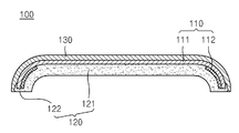
도 1은 본 발명의 제 1 실시예에 따른 커버 윈도우(100)의 폭 방향의 단면을 보여주는 개념도이다. 도 2는 도 1에 도시된 커버 윈도우(100)를 제조하기 위한 금형을 보여주는 개념도이다. FIG. 1 is a conceptual view showing a widthwise section of a
도 1 및 도 2를 참고하면, 커버 윈도우(100)는 필름층(110)을 포함할 수 있다. 이때, 필름층(110)은 필름바디부(111)와, 필름바디부(111)의 적어도 일부분에 형성되는 차광층(112)을 포함할 수 있다. Referring to FIGS. 1 and 2, the
필름바디부(111)는 적어도 일부분이 절곡되도록 형성될 수 있다. 이때, 필름바디부(111)는 다양한 형태로 절곡될 수 있다. 예를 들면, 필름바디부(111)는 하나의 곡률반경으로 곡면 형태로 형성될 수 있다. 또한, 필름바디부(111)는 한 부분만 절곡되도록 형성될 수 있다. 예를 들면, 필름바디부(111)의 테두리를 제외한 부분은 평평하게 형성되며, 필름바디부(111)의 테두리만이 절곡되도록 형성될 수 있다. 이때, 필름바디부(111)의 테두리는 양쪽이 절곡되도록 형성될 수 있으며, 필름바디부(111)의 테두리는 한쪽만 절곡되도록 형성될 수 있다. The
필름바디부(111)는 상기의 경우 이외에도 곡률반경이 서로 상이한 복수개의 곡면으로 형성될 수 있다. 구체적으로 필름바디부(111)는 제 1 곡률반경을 갖는 제 1 곡면 내지 제 N 곡률반경을 갖는 제 N 곡면을 포함할 수 있다.(여기서 N은 자연수) 이때, 제 1 곡면 내지 제 N 곡면은 서로 연결되도록 형성될 수 있다. The
특히 필름바디부(111)의 형태는 상기에 한정되지 않으며, 필름바디부(111)의 적어도 일부분이 절곡되도록 형성되는 형태는 모두 포함할 수 있다. Particularly, the shape of the
또한, 필름바디부(111)의 절곡되는 부분은 필름바디부(111)의 길이 방향 및 폭 방향 중 적어도 하나일 수 있다. 구체적으로 필름바디부(111)는 필름바디부(111)의 길이 방향으로 절곡도록 형성될 수 있으며, 필름바디부(111)는 필름바디부(111)의 폭 방향으로 절곡되도록 형성될 수 있다. 또한, 필름바디부(111)는 필름바디부(111)의 길이 방향 및 폭 방향으로 모두 절곡되도록 형성될 수 있다. The bent portion of the
이때, 이하에서는 설명의 편의를 위하여 필름바디부(111)의 테두리만이 절곡되도록 형성되는 경우를 중심으로 상세히 설명하기로 한다. 또한, 설명의 편의를 위하여 필름바디부(111)는 폭 방향으로 절곡되도록 형성되며, 필름바디부(111)의 양 테두리가 모두 절곡되도록 형성되는 경우를 중심으로 상세히 설명하기로 한다. Hereinafter, for the sake of convenience of explanation, a description will be made mainly on the case where only the rim of the
또한, 상기와 같은 필름바디부(111)는 다양한 방향으로 절곡될 수 있다. 예를 들면, 필름바디부(111)는 도 1의 상측 방향으로 볼록하도록 형성될 수 있으며, 도 1의 하측 방향으로 볼록하도록 형성되는 것도 가능하다. 다만, 이하에서는 설명의 편의를 위하여 필름바디부(111)가 도 1의 상측 방향으로 볼록하도록 형성되는 경우를 중심으로 상세히 설명하기로 한다. In addition, the
상기와 같은 필름바디부(111)는 투명한 재질로 형성될 수 있다. 예를 들면, 필름바디부(111)는 폴리메틸메타크릴레이트(PMMA, polymethylmethacrylate), 폴리카보네이트(PC, Polycabonate), 폴리에틸렌 테레프탈레이트(PET, Polyethylene terephthalate), 폴리에틸렌 테레프탈레이트 그리콜(PETG, Polyethylene terephthalate Glycol) 및 아크릴로나이트릴 부타디엔 스타이렌(Acrylonitrile butadiene styrene) 중 적어도 하나를 포함할 수 있다. 이때, 상기의 물질은 수지 형태로 제공되어 필름바디부(111)를 형성할 수 있다. 또한, 필름바디부(111)는 상기의 물질에 한정되지 않으며, 사출이 가능하며 투명한 재질을 모두 포함할 수 있다. The
차광층(112)은 잉크젯 프린팅 공정, 실크 스크린 공정 또는 임프린트 공정 등으로 형성할 수 있다. 이때, 잉크젯 프린팅 공정, 실크 스크린 공정 또는 임프린트 공정 등은 일반적인 공정과 동일하므로 상세한 설명은 생략하기로 한다. 또한, 차광층(112)을 형성하는 방법은 상기에 한정되지 않으며, 필름바디부(111)에 불투명한 층을 형성하는 모든 방법을 포함할 수 있다. The
차광층(112)은 상기에서 설명한 바와 같이 필름바디부(111)의 적어도 일부분에 형성될 수 있다. 특히 차광층(112)은 필름바디부(111)의 테두리부에 형성될 수 있다. The
한편, 커버 윈도우(100)는 필름층(110)에 형성되며, 필름층(110) 테두리를 감싸도록 형성되는 레진층(120)을 포함할 수 있다. 이때, 레진층(120)은 바디부(121)와, 바디부(121)로부터 연장되어 형성되며, 필름층(110)의 테두리를 감싸도록 형성되는 지지부(122)를 포함할 수 있다. Meanwhile, the
상기와 같은 바디부(121)는 필름바디부(111)와 동일한 형상으로 형성될 수 있다. 구체적으로 필름바디부(111)의 적어도 일부분이 절곡되는 경우 바디부(121)도 필름바디부(111)를 따라 적어도 일부분이 절곡되도록 형성될 수 있다. 이때, 필름바디부(111)와 바디부(121)의 곡면은 서로 유사한 곡률을 갖도록 형성될 수 있다. The
상기와 같은 바디부(121)는 투명한 재질로 형성될 수 있다. 예를 들면, 바디부(121)는 폴리메틸메타크릴레이트(PMMA, polymethylmethacrylate), 폴리카보네이트(PC, Polycabonate), 폴리에틸렌 테레프탈레이트(PET, Polyethylene terephthalate), 폴리에틸렌 테레프탈레이트 그리콜(PETG, Polyethylene terephthalate Glycol) 및 아크릴로나이트릴 부타디엔 스타이렌(Acrylonitrile butadiene styrene) 중 적어도 하나를 포함할 수 있다. 이때, 상기의 물질은 수지 형태로 제공되어 바디부(121)를 형성할 수 있다. 또한, 바디부(121)는 상기의 물질에 한정되지 않으며, 사출이 가능하며 투명한 재질을 모두 포함할 수 있다.The
상기와 같은 바디부(121) 및 필름바디부(111)는 서로 상이한 재질 또는 동일한 재질로 형성될 수 있다. 특히 바디부(121)와 필름바디부(111)가 서로 동일한 재질로 형성되는 경우 바디부(121)와 필름바디부(111)는 서로 화학적 결합을 통하여 견고하게 결합할 수 있다. The
지지부(122)는 절곡되도록 형성될 수 있다. 구체적으로 지지부(122)는 필름바디부(111)가 내부에 삽입되도록 홈을 구비할 수 있다. 이때, 지지부(122)는 필름바디부(111)의 테두리를 고정시킴으로써 필름바디부(111)의 테두리가 바디부(121) 또는 지지부(122)로부터 이탈하는 것을 방지할 수 있다. The
한편, 커버 윈도우(100)는 필름층(110)에 형성되는 보호층(130)을 포함할 수 있다. 이때, 보호층(130)은 레진층(120)과 대향하도록 필름층(110)에 형성될 수 있다. 구체적으로 레진층(120)이 필름층(110)의 제 1 외면(111a)에 형성되는 경우 보호층(130)은 제 1 외면(111a)과 상이한 필름층(110)의 제 2 외면(111b)에 형성될 수 있다. 또한, 레진층(120)이 제 2 외면(111b)에 형성되는 경우 보호층(130)은 제 1 외면(111a)에 형성되는 것도 가능하다. 다만, 이하에서는 설명의 편의를 위하여 보호층(130)이 제 1 외면(111a)에 형성되고, 레진층(120)은 제 2 외면(111b)에 형성되는 경우를 중심으로 상세히 설명하기로 한다. Meanwhile, the
이때, 보호층(130)은 외력, 이물질 차단, 정전기 방지 등과 같은 기능을 수행하는 재질로 형성될 수 있다. 구체적으로 보호층(130)은 아크릴계 재질로 형성될 수 있다. 또한, 보호층(130)은 유기물 및 무기물의 복합층으로 형성되는 것도 가능하다. 이때, 보호층(130)은 필름 형태로 필름층(110)에 부착되는 것도 가능하고, 코팅 공정을 통하여 형성되는 것도 가능하다. 다만, 이하에서는 설명의 편의를 위하여 보호층(130)을 코팅 공정을 통하여 형성되는 경우를 중심으로 상세히 설명하기로 한다. At this time, the
상기와 같은 보호층(130)은 필름층(110)의 테두리를 감싸는 레진층(120)의 일부분과 필름층(110)의 일부분에 형성될 수 있다. 구체적으로 보호층(130)은 바디부(121)와 지지부(122)를 덮도록 형성되어 바디부(121) 및 지지부(122)의 일부를 외부로부터 차단할 수 있다. The
한편, 상기와 같이 형성되는 커버 윈도우(100)의 제조방법을 살펴보면, 우선 상기에서 설명한 것과 같은 재질의 필름층(110)을 형성할 수 있다. 이때, 필름층(110)은 필름바디부(111)를 형성한 후 차광층(112)을 필름바디부(111)의 적어도 일부분에 잉크젯 프린팅 공정, 실크 스크린 공정 또는 임프린트 공정 등으로 형성할 수 있다. 이때, 잉크젯 프린팅 공정, 실크 스크린 공정 또는 임프린트 공정 등은 일반적인 공정과 동일하므로 상세한 설명은 생략하기로 한다.Meanwhile, in the method of manufacturing the
상기의 과정이 완료되면, 필름바디부(111)의 양 테두리를 절곡시킬 수 있다. 이때, 절곡하는 방법은 다양하게 형성될 수 있으며, 지그 등을 통하여 압착 또는 가압함으로써 절곡시킬 수 있다. When the above process is completed, both edges of the
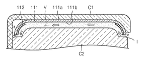
필름바디부(111)의 절곡이 완료되면, 필름바디부(111)를 금형(미표기) 내부에 배치할 수 있다. 이때, 상기 금형은 제 1 금형(C1)과 제 2 금형(C2)을 포함하며, 제 1 금형(C1)과 제 2 금형(C2)은 서로 이격되도록 배치되어 내부에 공간(V)을 형성할 수 있다. When the bending of the
필름바디부(111)가 공간(V)에 배치되는 경우 필름바디부(111)의 제 1 외면(111a)은 제 1 금형(C1)의 표면에 완전히 밀착할 수 있다. 이때, 필름바디부(111)의 제 1 외면(111a) 중 테두리의 제 1 외면은 제 1 금형(C1)의 표면으로부터 이격되도록 배치될 수 있다. When the
상기와 같이 필름바디부(111)를 배치한 후 레진(Resin)을 주입하여 사출할 수 있다. 이때, 상기 레진은 인몰드라벨링(IML, In-mold-labeling) 공정으로 필름층(110)에 살출되어 레진층(120)을 형성할 수 있다. 특히 상기 레진은 200℃ 내지 300℃ 범위에서 사출될 수 있다. After the
또한, 상기 레진은 상기 레진층(120)을 형성하는 재질인 폴리메틸메타크릴레이트(PMMA, polymethylmethacrylate), 폴리카보네이트(PC, Polycabonate), 폴리에틸렌 테레프탈레이트(PET, Polyethylene terephthalate), 폴리에틸렌 테레프탈레이트 그리콜(PETG, Polyethylene terephthalate Glycol) 및 아크릴로나이트릴 부타디엔 스타이렌(Acrylonitrile butadiene styrene) 중 적어도 하나를 포함하는 수지일 수 있다. The resin may be selected from the group consisting of polymethylmethacrylate (PMMA), polycarbonate (PC), polyethyleneterephthalate (PET), polyethylene terephthalate (PETG), polyethylene terephthalate (Glycol), and acrylonitrile butadiene styrene.
한편, 상기와 같이 상기 레진이 주입되는 경우 상기 레진은 필름바디부(111)의 테두리로부터 주입될 수 있다. 구체적으로 상기 레진은 필름바디부(111)의 길이 방향의 테두리 및 필름바디부(111)의 폭 방향의 테두리로부터 필름바디부(111)의 중심방향으로 주입될 수 있다. 특히 상기와 같이 필름바디부(111)의 테두리에서 필름바디부(111)의 중심방향으로 상기 레진이 주입되면, 커버 윈도우(100)는 상기 레진의 유동에 따른 무늬가 필름바디부(111)의 테두리 영역에 형성됨으로써 향후 디스플레이 패널(미도시)을 커버 윈도우(100)에 부착 시 시인성이 저하되거나 제품 불량이 발생하는 것을 방지할 수 있다. Meanwhile, when the resin is injected as described above, the resin may be injected from the rim of the
상기와 같이 상기 레진이 주입되어 사출되는 경우 제 1 금형(C1)와 필름바디부(111)의 테두리 및 제 2 금형(C2)와 필름바디부(111)의 테두리 사이로 상기 레진이 유입될 수 있다. 이때, 상기 레진은 제 1 금형(C1) 및 제 2 금형(C2) 중 적어도 하나에 의하여 필름바디부(111)의 테두리를 감싸도록 유동할 수 있다. 구체적으로 제 2 금형(C2)과 필름바디부(111)의 제 2 외면(111b) 사이로 주입된 상기 레진은 제 1 금형(C1)의 측면을 따라 필름바디부(111)의 제 1 외면(111a) 일부로 유동할 수 있다. 또한, 상기 레진은 제 1 금형(C1)과 제 2 금형(C2) 사이에 형성된 레진주입구(I) 부분에서 필름바디부(111)의 제 1 외면 일부로 유동할 수 있다. When the resin is injected and injected as described above, the resin may flow between the edges of the first mold C1 and the
상기와 같이 상기 레진의 주입되는 동안 상기 레진과 필름바디부(111)의 재질이 동일한 경우, 상기에서 설명한 사출 온도에 따라서 필름바디부(111)의 재질 일부가 녹아 상기 레진과 화학결합을 할 수 있다. 따라서 상기 레진을 주입한 후 상기 레진을 경화시켜 레진층(120)을 형성하는 경우 상기 화학결합에 의하여 레진층(120)과 필름바디부(111)는 견고하게 결합할 수 있다. When the resin and the
한편, 상기와 같은 작업이 완료된 후 온도를 하강시켜 상기 레진을 경화하여 레진층(120)을 형성할 수 있다. 이때, 상기 레진의 의하여 형성되는 레진층(120)의 면적은 필름층(110)의 면적보다 크게 형성될 수 있다. 구체적으로 레진층(120)의 길이는 필름층(110)의 길이보다 크게 형성될 수 있으며, 레진층(120)의 폭은 필름층(110)의 폭보다 크게 형성될 수 있다. 또한, 레진층(120)의 길이 및 폭은 필름층(110)의 길이 및 폭보다 크게 형성될 수 있다. 따라서 지지부(122)는 필름바디부(111)의 테두리를 완전히 감쌀 수 있다. On the other hand, after the above-described operation is completed, the
상기의 과정이 완료되면, 필름층(110) 및 레진층(120)을 제 1 금형(C1) 및 제 2 금형(C2) 외부로 인출할 수 있다. 또한, 필름층(110)의 제 1 외면(111a)에 보호층(130)을 형성할 수 있다. 이때, 보호층(130)은 상기에서 설명한 바와 같이 코팅 공정을 통하여 형성할 수 있다. 구체적으로 보호층(130)은 상기에서 설명한 아크릴계 재질이나 유기물 및 무기물을 교번하여 스프레이(Spray) 방식이나 딥-코팅(Dip-coating) 방식으로 형성할 수 있다. 이때, 상기 스프레이 방식이나 딥-코팅 방식은 일반적인 방식이므로 상세한 설명은 생략하기로 한다. When the above process is completed, the
상기와 같이 보호층(130)을 형성하는 경우, 보호층(130)은 필름바디부(111)의 제 1 외면과 지지부(122)의 일부에 형성될 수 있다. 이때, 보호층(130)은 필름바디부(111)의 제 1 외면(111a)과 지지부(122)의 일부를 외력, 외부의 이물질, 정전기 등으로부터 보호할 수 있다. When the
한편, 상기와 같이 레진층(120)이 형성되는 경우 지지부(122)는 상기에서 설명한 바와 같이 필름바디부(111)의 테두리를 지지할 수 있다. 구체적으로 필름바디부(111)의 테두리가 절곡되는 경우 필름바디부(111)를 형성하는 재질의 복원력에 의하여 필름바디부(111)의 테두리와 레진층(120)이 분리될 수 있다. 이때, 지지부(122)는 상기에서 설명한 바와 같이 필름바디부(111)의 테두리를 감싸도록 형성됨으로써 필름바디부(111)의 테두리가 레진층(120)과 분리되는 것을 방지할 수 있다. 또한, 지지부(122)는 필름바디부(111)가 열에 의하여 변형되는 경우 필름바디부(111)의 테두리를 지지함으로써 필름바디부(111)와 레진층(120)이 서로 분리되는 것을 방지할 수 있다. Meanwhile, when the
따라서 커버 윈도우(100) 및 커버 윈도우의 제조방법은 필름바디부(111)와 레진층(120)을 견고하게 결합시킴으로써 커버 윈도우(100)의 불량을 최소화할 수 있다. 뿐만 아니라 커버 윈도우의 제조방법은 간편하게 작업함으로써 작업 시간 및 작업 비용을 저감시킬 수 있다. Therefore, the manufacturing method of the
도 3은 본 발명의 제 2 실시예에 따른 커버 윈도우(200)의 폭 방향의 단면을 보여주는 개념도이다. 이하에서 도 1 및 도 2와 동일한 부호는 동일한 부재를 나타낸다. 3 is a conceptual view showing a widthwise section of the
도 3을 참고하면, 커버 윈도우(200)는 필름층(210), 레진층(220) 및 보호층(230)을 포함할 수 있다. 필름층(210)은 필름바디부(211) 및 차광층(212)을 포함할 수 있다. 또한, 레진층(220)은 바디부(221) 및 지지부(222)를 포함할 수 있다. Referring to FIG. 3, the
이때, 필름층(210), 레진층(220) 및 보호층(230)은 상기 도 1에서 설명한 필름층(110), 레진층(120) 및 보호층(130)과 유사하므로 상세한 설명은 생략하기로 한다.Since the
한편, 레진층(220)은 필름층(210)의 테두리와 보호층(230)의 테두리를 감싸도록 형성될 수 있다. 구체적으로 지지부(222)는 필름층(210)의 테두리와 보호층(230)의 테두리를 감싸도록 형성될 수 있다. 이때, 지지부(222)는 절곡된 필름층(210)의 테두리가 레진층(220)으로부터 분리되는 것을 방지할 수 있다. 특히 지지부(222)는 필름바디부(211) 테두리의 제 2 외면(211b)과 보호층(230)의 일부를 감싸도록 형성될 수 있다. Meanwhile, the
상기와 같이 형성되는 커버 윈도우(200)의 제조방법을 살펴보면, 상기에서 설명한 것과 유사하게 수행될 수 있다. The method of manufacturing the
구체적으로 필름층(210)을 제조하여 준비할 수 있다. 이때, 필름바디부(211)는 상기에서 설명한 것과 유사하게 형성되며, 차광층(212)은 잉크젯 프린팅 공정, 실크 스크린 공정 또는 임프린트 공정 등으로 형성할 수 있다. 이때, 잉크젯 프린팅 공정, 실크 스크린 공정 또는 임프린트 공정 등은 일반적인 공정과 동일하므로 상세한 설명은 생략하기로 한다.Specifically, the
상기의 과정이 완료되면, 필름바디부(211)의 제 2 외면(211b)에 보호층(230)을 형성할 수 있다. 이때, 보호층(230)은 필름바디부(211)의 제 2 외면 전체를 덮도록 형성될 수 있다.When the above process is completed, the
상기와 같이 보호층(230)이 형성되면, 필름바디부(211)와 보호층(230)을 절곡시킬 수 있다. 이때, 필름바디부(211)와 보호층(230)은 상기에서 설명한 바와 같이 지그 등을 통하여 절곡될 수 있으며, 다양한 형태의 곡면을 포함하도록 절곡될 수 있다. 특히, 필름바디부(211)의 테두리를 절곡시킬 수 있다. When the
상기와 같이 필름바디부(211)와 보호층(230)이 절곡되면, 필름바디부(211)와 보호층(230)을 제 1 금형(C1) 및 제 2 금형(C2) 사이에 배치할 수 있다. 이때, 보호층(230)의 외면 일부분은 제 1 금형(C1)의 표면에 접촉할 수 있다. When the
한편, 상기의 과정이 완료되면, 제 2 금형(C2)과 필름바디부(211)의 제 2 외면(211b) 사이로 레진(Resin)을 주입할 수 있다. 이때, 상기 레진을 주입하는 방향은 상기에서 설명한 바와 같이 필름바디부(211)의 테두리로부터 필름바디부(211)의 중심방향으로 주입할 수 있다. Meanwhile, when the above process is completed, a resin may be injected between the second mold C2 and the second
상기와 같이 상기 레진을 주입하는 경우 상기 레진은 필름바디부(211)와 제 2 금형 사이의 공간으로 유입될 수 있다. 또한, 상기 레진 중 일부는 필름바디부(211)의 제 1 외면(211a)에 형성된 보호층(230)의 일부분 상으로 유동할 수 있다. 이때, 시간이 경과함에 따라 상기 레진은 경화되어 레진층(220)을 형성하고, 레진층(220)은 바디부(221)와 지지부(222)가 형성될 수 있다. 특히 지지부(222)는 상기에서 설명한 바와 같이 필름바디부(211)의 절곡된 테두리를 감싸도록 형성될 수 있다. 또한, 지지부(222)는 필름바디부(211)의 테두리에 형성되는 보호층(230)의 표면을 덮도록 형성될 수 있다. When the resin is injected as described above, the resin may flow into the space between the
이때, 상기와 같이 상기 레진이 주입되는 동안 상기 레진과 필름바디부(211)의 재질이 동일한 경우 필름바디부(211)의 일부가 용융되어 레진층(220)과 화학결합을 수행할 수 있다. When the resin and the
따라서 커버 윈도우(200) 및 커버 윈도우의 제조방법은 필름바디부(211)의 테두리 및 보호층(230)의 일부를 감싸는 지지부(222)를 구비함으로써 필름바디부(211)의 절곡된 테두리가 레진층(220)으로부터 이탈되는 것을 방지할 수 있다. 뿐만 아니라 커버 윈도우(200) 및 커버 윈도우의 제조방법은 동일한 재질인 경우 레진층(220)과 필름바디부(211) 사이의 화학결합으로 인하여 견고한 결합을 제공할 수 있다. The method of manufacturing the
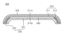
도 4는 본 발명의 제 3 실시예에 따른 커버 윈도우(300)의 폭 방향의 단면을 보여주는 개념도이다.4 is a conceptual view showing a widthwise section of the
도 4를 참고하면, 커버 윈도우(300)는 필름층(310), 레진층(320) 및 보호층(330)을 포함할 수 있다. 필름층(310)은 필름바디부(311) 및 차광층(312)을 포함할 수 있다. 또한, 레진층(320)은 바디부(321) 및 지지부(322)를 포함할 수 있다. Referring to FIG. 4, the
이때, 필름층(310), 레진층(320) 및 보호층(330)은 상기 도 1에서 설명한 필름층(110), 레진층(120) 및 보호층(130)과 유사하므로 상세한 설명은 생략하기로 한다.Since the
커버 윈도우(300)는 필름층(310)과 레진층(320) 사이에 형성되는 바인더층(340)을 포함할 수 있다. 이때, 바인더층(340)은 실크 스크린 공정(Silk screen printing)을 통하여 필름바디부(311)에 형성될 수 있다. 구체적으로 바인더층(340)은 필름바디부(311)의 제 2 외면(311b)에 형성될 수 있다. 특히 바인더층(340)은 필름층(310)의 면적과 동일하거나 필름층(310)의 면적보다 작게 형성될 수 있다. The
바인더층(340)은 다양한 재질로 형성될 수 있다. 예를 들면, 바인더층(340)은 폴리메틸메타크릴레이트(PMMA, polymethylmethacrylate), 폴리카보네이트(PC, Polycabonate), 폴리에틸렌 테레프탈레이트(PET, Polyethylene terephthalate), 폴리에틸렌 테레프탈레이트 그리콜(PETG, Polyethylene terephthalate Glycol) 및 아크릴로나이트릴 부타디엔 스타이렌(Acrylonitrile butadiene styrene) 중 적어도 하나를 포함을 포함할 수 있다. 이때, 필름층(310), 레진층(320) 및 바인더층(340)은 서로 상이한 재질로 형성되거나 필름층(310), 레진층(320) 및 바인더층(340) 중 적어도 두개는 동일한 재질로 형성될 수 있다. 다만, 이하에서는 설명의 편의를 위하여 필름층(310), 레진층(320) 및 바인더층(340)이 서로 동일한 재질로 형성되는 경우를 중심으로 상세히 설명하기로 한다. The
한편, 상기와 같이 형성되는 커버 윈도우(300)의 제조방법을 살펴보면, 상기에서 설명한 것과 유사하게 형성될 수 있다. The method of manufacturing the
구체적으로 필름바디부(311)를 제조한 후 필름바디부(311)의 적어도 일부분에 차광층(312)을 형성할 수 있다. 차광층(312)은 잉크젯 프린팅 공정, 실크 스크린 공정 또는 임프린트 공정 등으로 형성할 수 있다. 이때, 잉크젯 프린팅 공정, 실크 스크린 공정 또는 임프린트 공정 등은 일반적인 공정과 동일하므로 상세한 설명은 생략하기로 한다. Specifically, the
상기의 공정이 완료되면, 필름바디부(311)를 절곡한 후 제 1 금형(C1)과 제 2 금형(C2) 사이로 인입시킬 수 있다. 이후 필름바디부(311)의 제 2 외면(311b)과 제 2 금형(C2) 사이로 레진을 주입하여 레진층(320)을 필름바디부(311)의 제 2 외면(311b)에 형성할 수 있다. 이때, 상기와 같이 상기 레진을 주입하는 경우 상기 레진은 바인더층(340)의 일부를 용융시키고 용융된 바인더층(340)의 일부와 화학결합할 수 있다. When the above process is completed, the
상기와 같이 레진층(320)이 형성되는 경우 바디부(321)와 지지부(322)가 형성되며, 지지부(322)는 필름바디부(311)의 테두리를 감싸도록 형성될 수 있다. 이때, 지지부(322)는 필름바디부(311)의 테두리가 삽입되어 필름바디부(311)가 바인더층(340)으로부터 분리되는 것을 방지할 수 있다. When the
상기의 과정이 완료되면, 필름바디부(311)의 제 1 외면(311a)에 보호층(330)을 형성할 수 있다. 이때, 보호층(330)을 형성하는 방법은 상기에서 상세히 설명하였으므로 상세한 설명은 생략하기로 한다. When the above process is completed, the
따라서 커버 윈도우(300) 및 커버 윈도우의 제조방법은 커버 윈도우(300)의 적어도 일부분을 절곡시키도록 제조하더라도 필름바디부(311) 테두리와 바인더층(340)의 테두리를 지지부(322)가 고정시킴으로써 필름바디부(311), 바인더층(340) 및 보호층(330)이 각각 분리되는 것을 방지할 수 있다. Therefore, even if the
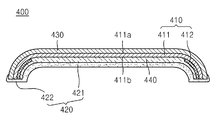
도 5는 본 발명의 제 4 실시예에 따른 커버 윈도우(400)의 폭 방향의 단면을 보여주는 개념도이다.5 is a conceptual view showing a widthwise section of a
도 5를 참고하면, 커버 윈도우(400)는 필름층(410), 레진층(420), 보호층(430) 및 바인더층(440)을 포함할 수 있다. 필름층(410)은 필름바디부(411) 및 차광층(412)을 포함할 수 있다. 또한, 레진층(420)은 바디부(421) 및 지지부(422)를 포함할 수 있다. 5, the
이때, 필름층(410), 레진층(420), 보호층(430) 및 바인더층(440)은 상기 도 4에서 설명한 필름층(310), 레진층(320), 보호층(330) 및 바인더층(340)과 유사하므로 상세한 설명은 생략하기로 한다.At this time, the
한편, 상기와 같이 형성되는 커버 윈도우(400)의 제조방법을 살펴보면, 필름바디부(411)에 상기에서 설명한 바와 같이 차광층(412)을 형성한 후 필름바디부(411)의 제 2 외면(411b)에 보호층(430)을 형성할 수 있다. 이때, 보호층(430)을 형성하는 방법은 상기에서 상세히 설명하였으므로 생략하기로 한다. The method of manufacturing the
또한, 필름바디부(411)의 제 1 외면(411a)에는 바인더층(440)을 형성할 수 있다. 이때, 바인더층(440)을 형성하는 방법은 상기에서 상세히 설명하였으므로 생략하기로 한다. In addition, a
상기와 같이 보호층(430) 및 바인더층(440)의 형성이 완료되면, 필름바디부(411)를 절곡시킬 수 있다. 이때, 필름바디부(411)를 절곡시키는 방법은 상기에서 상세히 설명하였으므로 상세한 설명은 생략하기로 한다. When the
상기와 같이 절곡된 필름층(410), 보호층(430) 및 바인더층(440)을 제 1 금형(C1)과 제 2 금형(C2) 사이에 진입시킨 후 레진을 주입할 수 있다. 이때, 상기 레진은 상기에서 설명한 바와 같이 필름층(410)의 테두리로부터 필름층(410)의 중심방향으로 주입될 수 있다. The resin film may be injected after the
상기와 같이 상기 레진이 주입되는 경우 상기 레진의 일부는 바인더층(440)과 제 2 금형(C2) 사이를 유동하여 필름바디부(411)의 테두리와 보호층(430)의 일부를 감쌀 수 있다. 이후 상기 레진을 경화시키면, 상기 레진은 레진층(420)을 형성할 수 있다. When the resin is injected as described above, a part of the resin flows between the
이때, 레진층(420)의 지지부(422)는 상기에서 설명한 바와 같이 필름바디부(411)의 테두리, 바인더층(440)의 테두리, 보호층(430)의 테두리가 각각 내부에 삽입되어 고정될 수 있다. 특히 지지부(422)는 절곡된 필름바디부(411)의 테두리가 원 상태로 복귀하는 것을 방지함으로써 필름바디부(411)가 바인더층(440)에서 분리되는 것을 방지하며, 바인더층(440)이 필름바디부(411)와 함께 움직이는 것을 방지하여 바인더층(440)과 레진층(420)이 서로 분리되는 것을 방지할 수 있다. At this time, the
따라서 커버 윈도우(400) 및 커버 윈도우의 제조방법은 절곡된 필름바디부(411)의 테두리가 원상태로 복귀하는 것을 방지함으로써 필름바디부(411), 바인더층(440) 및 레진층(420)이 각각 분리되는 것을 방지할 수 있다. Accordingly, the
특히 커버 윈도우(400) 및 커버 윈도우의 제조방법은 커버 윈도우(400)의 테두리 영역에서 발생하는 박리 현상을 방지함으로써 불량률을 최소화할 수 있다. Particularly, the manufacturing method of the
비록 본 발명이 상기 언급된 바람직한 실시예와 관련하여 설명되었지만, 발명의 요지와 범위로부터 벗어남이 없이 다양한 수정이나 변형을 하는 것이 가능하다. 따라서 첨부된 특허청구의 범위에는 본 발명의 요지에 속하는 한 이러한 수정이나 변형을 포함할 것이다.Although the present invention has been described in connection with the above-mentioned preferred embodiments, it is possible to make various modifications and variations without departing from the spirit and scope of the invention. Accordingly, it is intended that the appended claims cover all such modifications and variations as fall within the true spirit of the invention.
C1: 제 1 금형
C2: 제 2 금형
100, 200, 300, 400 : 커버 윈도우
110, 210, 310, 410 : 필름층
120, 220, 320, 420 : 레진층
130, 230, 330, 430 : 보호층
340, 440: 바인더층C1: First mold
C2: second mold
100, 200, 300, 400: Cover window
110, 210, 310, 410: a film layer
120, 220, 320, 420: Resin layer
130, 230, 330, 430: protective layer
340, 440: a binder layer
Claims (19)
상기 필름층에 형성되며 상기 필름층 테두리를 감싸도록 형성되는 레진층;을 포함하는 커버 윈도우.A film layer; And
And a resin layer formed on the film layer and formed to surround the edge of the film layer.
상기 필름층의 적어도 일부분 및 상기 레진층의 적어도 일부분은 굴곡지게 형성되는 커버 윈도우.The method according to claim 1,
Wherein at least a portion of the film layer and at least a portion of the resin layer are curved.
상기 필름층의 면적은 상기 레진층의 면적보다 작게 형성되는 커버 윈도우.The method according to claim 1,
Wherein an area of the film layer is smaller than an area of the resin layer.
상기 필름층 및 상기 레진층은 동일한 재질로 형성되는 커버 윈도우.The method according to claim 1,
Wherein the film layer and the resin layer are formed of the same material.
상기 필름층은,
필름바디부; 및
상기 필름바디부의 적어도 일부분에 형성되는 차광층;를 구비하는 커버 윈도우.The method according to claim 1,
Wherein the film layer comprises:
A film body portion; And
And a light shielding layer formed on at least a portion of the film body portion.
상기 레진층은,
바디부; 및
상기 바디부로부터 연장되어 형성되며, 상기 필름층 테두리를 감싸도록 형성되는 지지부;를 구비하는 커버 윈도우.The method according to claim 1,
Wherein the resin layer comprises:
Body part; And
And a support portion extending from the body portion, the support portion being formed to surround the edge of the film layer.
상기 필름층을 중심으로 상기 레진층과 대향하도록 상기 필름층의 적어도 일부분에 형성되는 보호층;을 더 포함하는 커버 윈도우.The method according to claim 1,
And a protective layer formed on at least a portion of the film layer to face the resin layer about the film layer.
상기 레진층은 상기 필름층의 테두리와 함께 상기 보호층의 테두리를 감싸도록 형성되는 커버 윈도우.8. The method of claim 7,
Wherein the resin layer is formed to surround the rim of the protective layer together with the rim of the film layer.
상기 보호층은 상기 필름층의 테두리를 감싸는 상기 레진층의 일부분과 상기 필름층의 일부분에 형성되는 커버 윈도우. 8. The method of claim 7,
Wherein the protective layer is formed on a portion of the resin layer and a portion of the film layer surrounding the rim of the film layer.
상기 필름층과 상기 레진층 사이에 형성되는 바인더층;을 더 포함하는 커버 윈도우.The method according to claim 1,
And a binder layer formed between the film layer and the resin layer.
상기 필름층, 상기 레진층 및 상기 바인더층 중 적어도 두개는 동일한 재질로 형성되는 커버 윈도우.11. The method of claim 10,
Wherein at least two of the film layer, the resin layer and the binder layer are formed of the same material.
상기 레진층은 레진(Resin)을 인몰드라벨링(IML, In-mold-labeling) 공정으로 상기 필름층에 사출하여 형성되는 커버 윈도우.The method according to claim 1,
Wherein the resin layer is formed by injecting a resin into the film layer by an in-mold-labeling (IML) process.
상기 필름층의 외면에 레진(Resin)을 사출하여 상기 필름층 테두리를 감싸도록 레진층을 형성하는 단계;를 포함하는 커버 윈도우의 제조방법.Bending at least a portion of the film layer; And
And forming a resin layer to surround the edge of the film layer by injecting a resin onto an outer surface of the film layer.
상기 레진층은 인몰드라벨링(IML, In-mold-labeling) 공정으로 상기 레진을 사출하여 형성하는 커버 윈도우의 제조방법.14. The method of claim 13,
Wherein the resin layer is formed by injection molding the resin by an in-mold-labeling (IML) process.
상기 필름층의 적어도 일부분을 절곡하기 전에 상기 필름층에 보호층을 형성하는 단계;를 더 포함하는 커버 윈도우의 제조방법.14. The method of claim 13,
And forming a protective layer on the film layer before bending at least a portion of the film layer.
상기 레진층을 사출하는 단계는 상기 필름층의 테두리 및 상기 보호층의 테두리를 감싸도록 사출되는 커버 윈도우의 제조방법.16. The method of claim 15,
Wherein the step of injecting the resin layer is performed so as to surround the rim of the film layer and the rim of the protective layer.
상기 필름층에 상기 레진을 사출하여 상기 레진층을 형성한 후 상기 필름층의 적어도 일부분과 상기 레진층의 적어도 일부분에 보호층을 형성하는 단계;를 더 포함하는 커버 윈도우의 제조방법.14. The method of claim 13,
And forming a protective layer on at least a portion of the film layer and at least a portion of the resin layer after the resin is injected into the film layer to form the resin layer.
상기 필름층의 적어도 일부분을 절곡하기 전에 상기 필름층에 바인더층을 형성하는 단계;를 더 포함하는 커버 윈도우의 제조방법.14. The method of claim 13,
And forming a binder layer on the film layer before bending at least a portion of the film layer.
상기 레진은 상기 필름층의 테두리측으로부터 중심 방향으로 주입되는 커버 윈도우의 제조방법.14. The method of claim 13,
Wherein the resin is injected in a center direction from a rim side of the film layer.
Priority Applications (3)
| Application Number | Priority Date | Filing Date | Title |
|---|---|---|---|
| KR1020130064333A KR102124047B1 (en) | 2013-06-04 | 2013-06-04 | Cover window |
| US14/047,201 US9958900B2 (en) | 2013-06-04 | 2013-10-07 | Cover window and manufacturing method of the same |
| US15/933,890 US11048297B2 (en) | 2013-06-04 | 2018-03-23 | Cover window and manufacturing method of the same |
Applications Claiming Priority (1)
| Application Number | Priority Date | Filing Date | Title |
|---|---|---|---|
| KR1020130064333A KR102124047B1 (en) | 2013-06-04 | 2013-06-04 | Cover window |
Related Child Applications (1)
| Application Number | Title | Priority Date | Filing Date |
|---|---|---|---|
| KR1020200038590A Division KR102131966B1 (en) | 2020-03-30 | 2020-03-30 | Manufacturing method of a cover window |
Publications (2)
| Publication Number | Publication Date |
|---|---|
| KR20140142633A true KR20140142633A (en) | 2014-12-12 |
| KR102124047B1 KR102124047B1 (en) | 2020-06-18 |
Family
ID=51984247
Family Applications (1)
| Application Number | Title | Priority Date | Filing Date |
|---|---|---|---|
| KR1020130064333A KR102124047B1 (en) | 2013-06-04 | 2013-06-04 | Cover window |
Country Status (2)
| Country | Link |
|---|---|
| US (2) | US9958900B2 (en) |
| KR (1) | KR102124047B1 (en) |
Cited By (5)
| Publication number | Priority date | Publication date | Assignee | Title |
|---|---|---|---|---|
| KR20170013482A (en) * | 2015-07-27 | 2017-02-07 | 삼성디스플레이 주식회사 | Display device |
| WO2017150778A1 (en) * | 2016-03-02 | 2017-09-08 | 주식회사 맥스젠테크놀로지 | Composite protection sheet to be attached to mobile device having curved surface part and manufacturing method therefor |
| KR20180019430A (en) * | 2016-08-16 | 2018-02-26 | 삼성전자주식회사 | Protecting Cover and Protecting Cover Package, and Electronic device including the same |
| US10096792B2 (en) | 2015-08-24 | 2018-10-09 | Samsung Display Co., Ltd. | Display device having window member and method of manufacturing window member |
| KR20190057473A (en) * | 2017-11-20 | 2019-05-29 | 현대자동차주식회사 | Curved surface display device and manufacturing method thereof |
Families Citing this family (12)
| Publication number | Priority date | Publication date | Assignee | Title |
|---|---|---|---|---|
| KR102338473B1 (en) * | 2014-12-26 | 2021-12-14 | 삼성전자주식회사 | Window cover and display apparatus having the same and method of manufacturing display apparatus |
| DE102015100208A1 (en) * | 2015-01-09 | 2016-07-14 | Leonhard Kurz Stiftung & Co. Kg | Process for producing a composite article and a composite article |
| US10559237B2 (en) * | 2015-07-24 | 2020-02-11 | The Boeing Company | Method for conforming a display panel |
| KR102603654B1 (en) * | 2016-08-24 | 2023-11-17 | 삼성디스플레이 주식회사 | Display device |
| KR102461107B1 (en) * | 2017-12-14 | 2022-10-31 | 삼성디스플레이 주식회사 | Cover glass and manufacturing method thereof |
| CN110599901B (en) * | 2018-06-12 | 2023-09-08 | 三星显示有限公司 | Window and display device including the same |
| CN109411646B (en) * | 2018-10-10 | 2021-09-03 | Oppo广东移动通信有限公司 | Electronic equipment battery cover plate, preparation method thereof and electronic equipment |
| JP7137441B2 (en) * | 2018-11-06 | 2022-09-14 | 本田技研工業株式会社 | Resin molded article and its manufacturing method |
| EP3785897B1 (en) | 2019-08-29 | 2021-12-29 | SHPP Global Technologies B.V. | Transparent, flexible, impact resistant, multilayer film comprising polycarbonate copolymers |
| CN110978384A (en) * | 2019-12-30 | 2020-04-10 | 东莞广华汽车饰件科技有限公司 | Pad printing protection manufacturing process of adhesive film ornament |
| KR20220037002A (en) * | 2020-09-16 | 2022-03-24 | 삼성디스플레이 주식회사 | Cover window, method of manufacturing for cover window, display device |
| CN114267254B (en) * | 2021-12-29 | 2023-05-09 | 武汉天马微电子有限公司 | Display module, manufacturing method thereof and display device |
Citations (3)
| Publication number | Priority date | Publication date | Assignee | Title |
|---|---|---|---|---|
| US20090301748A1 (en) * | 2008-06-06 | 2009-12-10 | Shenzhen Futaihong Precision Industry Co., Ltd. | Housing, electronic device using the housing, and manufacturing method thereof |
| JP2012006381A (en) * | 2010-06-28 | 2012-01-12 | Sutech Trading Ltd | Injection-molded product and method for manufacturing the same |
| KR101212172B1 (en) * | 2012-07-31 | 2012-12-13 | 한국기계연구원 | Display device |
Family Cites Families (13)
| Publication number | Priority date | Publication date | Assignee | Title |
|---|---|---|---|---|
| CH618595A5 (en) * | 1976-08-07 | 1980-08-15 | Max Meier | Board, in particular table top, and process and device for the production thereof |
| DE10013410B4 (en) * | 2000-03-17 | 2011-05-05 | Ovd Kinegram Ag | Laminate, in particular in the form of cards, and process for its production |
| US6768654B2 (en) * | 2000-09-18 | 2004-07-27 | Wavezero, Inc. | Multi-layered structures and methods for manufacturing the multi-layered structures |
| TWI368568B (en) | 2007-05-31 | 2012-07-21 | Nissha Printing | Laminated product for insertion molding, method of its manufacture, insert molded product and method of its manufacture |
| US20090009941A1 (en) * | 2007-07-04 | 2009-01-08 | Shenzhen Futaihong Precision Industry Co., Ltd. | Housing for an electronic device, electronic device using the housing, and method for making the housing |
| US20090160087A1 (en) * | 2007-12-19 | 2009-06-25 | Gawain Yang | In-mold decoration method & apparatus |
| JP2009166372A (en) | 2008-01-16 | 2009-07-30 | Aiska Internatl Co Ltd | In-mold forming method for printed decorative body |
| CN101856858A (en) * | 2009-04-08 | 2010-10-13 | 康准电子科技(昆山)有限公司 | Method for forming in-mold decoration mold product with microstructure and mold product thereof |
| CN101879799A (en) * | 2009-05-04 | 2010-11-10 | 富准精密工业(深圳)有限公司 | Shell and manufacturing method thereof |
| KR101141307B1 (en) | 2009-12-22 | 2012-05-04 | 이상근 | Injection Molding Production and Method for Producing thereof |
| JP4820452B1 (en) * | 2010-06-29 | 2011-11-24 | 株式会社三和スクリーン銘板 | Method for producing metal-like decorative sheet and method for producing insert-molded body using metal-like decorative sheet |
| WO2012037094A2 (en) * | 2010-09-14 | 2012-03-22 | Corning Incorporated | Appliance fascia and mounting therefore |
| KR101879590B1 (en) | 2011-07-29 | 2018-07-20 | 삼성전자주식회사 | Display window member for portable terminal and fabrication method thereof |
-
2013
- 2013-06-04 KR KR1020130064333A patent/KR102124047B1/en active IP Right Grant
- 2013-10-07 US US14/047,201 patent/US9958900B2/en active Active
-
2018
- 2018-03-23 US US15/933,890 patent/US11048297B2/en active Active
Patent Citations (3)
| Publication number | Priority date | Publication date | Assignee | Title |
|---|---|---|---|---|
| US20090301748A1 (en) * | 2008-06-06 | 2009-12-10 | Shenzhen Futaihong Precision Industry Co., Ltd. | Housing, electronic device using the housing, and manufacturing method thereof |
| JP2012006381A (en) * | 2010-06-28 | 2012-01-12 | Sutech Trading Ltd | Injection-molded product and method for manufacturing the same |
| KR101212172B1 (en) * | 2012-07-31 | 2012-12-13 | 한국기계연구원 | Display device |
Cited By (7)
| Publication number | Priority date | Publication date | Assignee | Title |
|---|---|---|---|---|
| KR20170013482A (en) * | 2015-07-27 | 2017-02-07 | 삼성디스플레이 주식회사 | Display device |
| US10096792B2 (en) | 2015-08-24 | 2018-10-09 | Samsung Display Co., Ltd. | Display device having window member and method of manufacturing window member |
| US10586944B2 (en) | 2015-08-24 | 2020-03-10 | Samsung Display Co., Ltd. | Display device having window member and method of manufacturing window member |
| WO2017150778A1 (en) * | 2016-03-02 | 2017-09-08 | 주식회사 맥스젠테크놀로지 | Composite protection sheet to be attached to mobile device having curved surface part and manufacturing method therefor |
| KR20180019430A (en) * | 2016-08-16 | 2018-02-26 | 삼성전자주식회사 | Protecting Cover and Protecting Cover Package, and Electronic device including the same |
| US11794451B2 (en) | 2016-08-16 | 2023-10-24 | Samsung Electronics Co., Ltd. | Protective cover, protective cover package comprising same, and electronic device comprising protective cover |
| KR20190057473A (en) * | 2017-11-20 | 2019-05-29 | 현대자동차주식회사 | Curved surface display device and manufacturing method thereof |
Also Published As
| Publication number | Publication date |
|---|---|
| KR102124047B1 (en) | 2020-06-18 |
| US9958900B2 (en) | 2018-05-01 |
| US20180210502A1 (en) | 2018-07-26 |
| US11048297B2 (en) | 2021-06-29 |
| US20140353874A1 (en) | 2014-12-04 |
Similar Documents
| Publication | Publication Date | Title |
|---|---|---|
| KR20140142633A (en) | Cover window and manufacturing method of the same | |
| KR102131962B1 (en) | Manufacturing device for a cover window and manufacturing method for the cover window | |
| CN102823338B (en) | Glass composite, electronic device using glass composite, and input device | |
| US10324560B2 (en) | Apparatus of display having detachable layer and method of manufacturing the display | |
| KR101996437B1 (en) | Transparent protection window, flexible display apparatus with the same and the method for manufacturing the transparent protection window | |
| KR102373615B1 (en) | Display device having window member and fabricating mathod for window member | |
| US20150169089A1 (en) | Surface Protection Film and Method of Making a Protection Film for a Touch Screen | |
| KR102141206B1 (en) | Window panel, manufacturing method thereof, and display apparatus including the window panel | |
| US20150208521A1 (en) | Display device and method of manufacturing the same | |
| US9597858B2 (en) | Method for manufacturing touch panel and molded article | |
| EP3144782A1 (en) | Cover window for touch screen panel having printing layer formed thereon and method for forming printing layer on cover window for touch screen panel | |
| KR101164632B1 (en) | Protection sheet for display of portable electronic device | |
| KR101713144B1 (en) | Manufacturing method of protective film for electronic device | |
| KR102131966B1 (en) | Manufacturing method of a cover window | |
| KR20150019204A (en) | Front window cover for touch screen display device and method for producing the same | |
| CN105334653B (en) | Display device and display device manufacturing method | |
| KR20130013767A (en) | Display window member for portable terminal and fabrication method thereof | |
| WO2016194323A1 (en) | Electronic apparatus and method for manufacturing same | |
| US20150002926A1 (en) | Reflective Mold Apparatus and Methods for UV Curing | |
| US10998296B2 (en) | In-vehicle display device using semiconductor light-emitting device | |
| US20160274698A1 (en) | Sensor panel and method of manufacturing sensor panel | |
| CN111527422B (en) | In-vehicle display apparatus using semiconductor light emitting device | |
| JP2012098973A (en) | Glass composite and input device using the glass composite | |
| KR102510188B1 (en) | Electronic devices, methods for manufacturing electronic devices, and substrate laminates | |
| JP6330871B2 (en) | Display device having detachable layer and manufacturing method thereof {Apparatus of display having layered layer and method of manufacturing the display} |
Legal Events
| Date | Code | Title | Description |
|---|---|---|---|
| A201 | Request for examination | ||
| E902 | Notification of reason for refusal | ||
| AMND | Amendment | ||
| E601 | Decision to refuse application | ||
| X091 | Application refused [patent] | ||
| A107 | Divisional application of patent | ||
| AMND | Amendment | ||
| X701 | Decision to grant (after re-examination) | ||
| GRNT | Written decision to grant |