KR20140139075A - Films comprising an array of openings and methods of making the same - Google Patents
Films comprising an array of openings and methods of making the same Download PDFInfo
- Publication number
- KR20140139075A KR20140139075A KR1020147029909A KR20147029909A KR20140139075A KR 20140139075 A KR20140139075 A KR 20140139075A KR 1020147029909 A KR1020147029909 A KR 1020147029909A KR 20147029909 A KR20147029909 A KR 20147029909A KR 20140139075 A KR20140139075 A KR 20140139075A
- Authority
- KR
- South Korea
- Prior art keywords
- openings
- micrometers
- polymer layer
- polymeric
- major surface
- Prior art date
Links
Images


Classifications
-
- B—PERFORMING OPERATIONS; TRANSPORTING
- B29—WORKING OF PLASTICS; WORKING OF SUBSTANCES IN A PLASTIC STATE IN GENERAL
- B29C—SHAPING OR JOINING OF PLASTICS; SHAPING OF MATERIAL IN A PLASTIC STATE, NOT OTHERWISE PROVIDED FOR; AFTER-TREATMENT OF THE SHAPED PRODUCTS, e.g. REPAIRING
- B29C43/00—Compression moulding, i.e. applying external pressure to flow the moulding material; Apparatus therefor
- B29C43/22—Compression moulding, i.e. applying external pressure to flow the moulding material; Apparatus therefor of articles of indefinite length
- B29C43/222—Compression moulding, i.e. applying external pressure to flow the moulding material; Apparatus therefor of articles of indefinite length characterised by the shape of the surface
-
- B—PERFORMING OPERATIONS; TRANSPORTING
- B29—WORKING OF PLASTICS; WORKING OF SUBSTANCES IN A PLASTIC STATE IN GENERAL
- B29C—SHAPING OR JOINING OF PLASTICS; SHAPING OF MATERIAL IN A PLASTIC STATE, NOT OTHERWISE PROVIDED FOR; AFTER-TREATMENT OF THE SHAPED PRODUCTS, e.g. REPAIRING
- B29C43/00—Compression moulding, i.e. applying external pressure to flow the moulding material; Apparatus therefor
- B29C43/22—Compression moulding, i.e. applying external pressure to flow the moulding material; Apparatus therefor of articles of indefinite length
- B29C43/24—Calendering
-
- B—PERFORMING OPERATIONS; TRANSPORTING
- B29—WORKING OF PLASTICS; WORKING OF SUBSTANCES IN A PLASTIC STATE IN GENERAL
- B29C—SHAPING OR JOINING OF PLASTICS; SHAPING OF MATERIAL IN A PLASTIC STATE, NOT OTHERWISE PROVIDED FOR; AFTER-TREATMENT OF THE SHAPED PRODUCTS, e.g. REPAIRING
- B29C48/00—Extrusion moulding, i.e. expressing the moulding material through a die or nozzle which imparts the desired form; Apparatus therefor
- B29C48/03—Extrusion moulding, i.e. expressing the moulding material through a die or nozzle which imparts the desired form; Apparatus therefor characterised by the shape of the extruded material at extrusion
- B29C48/07—Flat, e.g. panels
- B29C48/08—Flat, e.g. panels flexible, e.g. films
-
- B—PERFORMING OPERATIONS; TRANSPORTING
- B29—WORKING OF PLASTICS; WORKING OF SUBSTANCES IN A PLASTIC STATE IN GENERAL
- B29C—SHAPING OR JOINING OF PLASTICS; SHAPING OF MATERIAL IN A PLASTIC STATE, NOT OTHERWISE PROVIDED FOR; AFTER-TREATMENT OF THE SHAPED PRODUCTS, e.g. REPAIRING
- B29C48/00—Extrusion moulding, i.e. expressing the moulding material through a die or nozzle which imparts the desired form; Apparatus therefor
- B29C48/03—Extrusion moulding, i.e. expressing the moulding material through a die or nozzle which imparts the desired form; Apparatus therefor characterised by the shape of the extruded material at extrusion
- B29C48/12—Articles with an irregular circumference when viewed in cross-section, e.g. window profiles
-
- B—PERFORMING OPERATIONS; TRANSPORTING
- B29—WORKING OF PLASTICS; WORKING OF SUBSTANCES IN A PLASTIC STATE IN GENERAL
- B29D—PRODUCING PARTICULAR ARTICLES FROM PLASTICS OR FROM SUBSTANCES IN A PLASTIC STATE
- B29D28/00—Producing nets or the like, e.g. meshes, lattices
-
- B—PERFORMING OPERATIONS; TRANSPORTING
- B29—WORKING OF PLASTICS; WORKING OF SUBSTANCES IN A PLASTIC STATE IN GENERAL
- B29D—PRODUCING PARTICULAR ARTICLES FROM PLASTICS OR FROM SUBSTANCES IN A PLASTIC STATE
- B29D7/00—Producing flat articles, e.g. films or sheets
- B29D7/01—Films or sheets
-
- B—PERFORMING OPERATIONS; TRANSPORTING
- B29—WORKING OF PLASTICS; WORKING OF SUBSTANCES IN A PLASTIC STATE IN GENERAL
- B29C—SHAPING OR JOINING OF PLASTICS; SHAPING OF MATERIAL IN A PLASTIC STATE, NOT OTHERWISE PROVIDED FOR; AFTER-TREATMENT OF THE SHAPED PRODUCTS, e.g. REPAIRING
- B29C48/00—Extrusion moulding, i.e. expressing the moulding material through a die or nozzle which imparts the desired form; Apparatus therefor
- B29C48/25—Component parts, details or accessories; Auxiliary operations
- B29C48/88—Thermal treatment of the stream of extruded material, e.g. cooling
- B29C48/911—Cooling
- B29C48/9135—Cooling of flat articles, e.g. using specially adapted supporting means
- B29C48/914—Cooling of flat articles, e.g. using specially adapted supporting means cooling drums
-
- B—PERFORMING OPERATIONS; TRANSPORTING
- B29—WORKING OF PLASTICS; WORKING OF SUBSTANCES IN A PLASTIC STATE IN GENERAL
- B29L—INDEXING SCHEME ASSOCIATED WITH SUBCLASS B29C, RELATING TO PARTICULAR ARTICLES
- B29L2028/00—Nets or the like
-
- Y—GENERAL TAGGING OF NEW TECHNOLOGICAL DEVELOPMENTS; GENERAL TAGGING OF CROSS-SECTIONAL TECHNOLOGIES SPANNING OVER SEVERAL SECTIONS OF THE IPC; TECHNICAL SUBJECTS COVERED BY FORMER USPC CROSS-REFERENCE ART COLLECTIONS [XRACs] AND DIGESTS
- Y10—TECHNICAL SUBJECTS COVERED BY FORMER USPC
- Y10T—TECHNICAL SUBJECTS COVERED BY FORMER US CLASSIFICATION
- Y10T428/00—Stock material or miscellaneous articles
- Y10T428/24—Structurally defined web or sheet [e.g., overall dimension, etc.]
- Y10T428/24273—Structurally defined web or sheet [e.g., overall dimension, etc.] including aperture
- Y10T428/24298—Noncircular aperture [e.g., slit, diamond, rectangular, etc.]
- Y10T428/24314—Slit or elongated
Abstract
대체로 대향하는 제1 및 제2 주 표면을 갖는 중합체 층은 상기 제1 주 표면과 상기 제2 주 표면 사이에 연장된 개구들의 어레이를 포함한다. 중합체 층은, 예를 들어, 기저귀 및 여성 위생 제품과 같은 개인용 케어 의류에서 구성요소로서 유용하다. 이는 또한 필터링(액체 필터링 포함) 및 음향 제품에 유용할 수 있다.A polymer layer having generally opposite first and second major surfaces includes an array of openings extending between the first major surface and the second major surface. The polymer layer is useful as a component in personal care garments such as, for example, diapers and feminine hygiene products. It can also be useful for filtering (including liquid filtration) and acoustic products.
Description
본 발명은 개구들의 어레이를 포함하는 필름 및 그의 제조 방법에 관한 것이다.The present invention relates to a film comprising an array of openings and a method of manufacturing the same.
관련 출원과의 상호 참조Cross reference to related application
본 출원은 그 개시 내용이 전체적으로 본원에 참고로 인용된, 2012년 3월 26일자로 출원된 미국 특허 가출원 제61/615,676호의 우선권을 주장한다.This application claims priority from U.S. Provisional Patent Application Serial No. 61 / 615,676, filed March 26, 2012, the disclosure of which is incorporated herein by reference in its entirety.
마크로다공성(macroporous)의 천공된 필름은 증기 및 액체 침투성 제품에 통상 사용되는 반면, 마이크로다공성(microporous)의 천공된 필름은 액체 침투성 제품이 아닌 증기 침투성 제품에 사용된다. 마크로다공성 천공 필름은 개인용 케어 의류(예를 들어, 기저귀 및 여성 위생 제품) 내의 구성요소로서 통상 사용된다. 천공 필름은 또한 필터링 및 음향 제품에 사용된다.While perforated films of macroporous are commonly used in steam and liquid permeable products, perforated films of microporous are used in vapor permeable products rather than liquid permeable products. Macro-porous perforated films are commonly used as components in personal care garments (e.g., diapers and feminine hygiene products). Perforated films are also used in filtering and acoustic products.
마크로다공성 침투성 필름은 먼저 연속 필름을 제조하고 이어서 이 필름이 천공 공정을 거치게 함으로써 통상 제조된다. 기계적 천공 장치는 상호맞물린(intermeshing) 롤러들, 다이 펀칭, 또는 니들펀칭을 포함한다. 필름은 또한 열 구역을 갖는 천공된 롤러 또는 필름 내에 천공부를 용융시키는 레이저를 이용하여 천공될 수 있다. 천공부를 제공하는 다른 기술들은 구멍 상에 진공부를 갖는 다공성 급랭 롤(porous quench roll) 상에 필름을 캐스팅하여 구멍 내의 용융물을 끌어당겨 개구부를 생성하는 것, 전기 코로나 처리를 이용하여 국부화된 에너지 처리에 의해 천공부를 생성하는 것, 및 비혼화성 재료를 블렌딩하고 이어서 필름 공극의 생성에 의해 천공부를 생성하도록 필름을 연신하여 천공부를 생성하는 것을 포함한다. 폴리프로필렌을 베타 상 결정으로 급랭한 후, 배향 시에, 필름이 다공성으로 될 것이라는 것이 또한 알려져 있다.The macroporous permeable film is usually prepared by first preparing a continuous film and then subjecting the film to a perforation process. The mechanical punching apparatus includes intermeshing rollers, die punching, or needle punching. The film may also be perforated using perforated rollers having thermal zones or lasers melting the perforations in the film. Other techniques for providing perforation include casting the film on a porous quench roll having pores on the pores to draw openings in the pores to create openings, Creating a perforation by energy treatment, and stretching the film to produce a perforation by blending the incompatible material and then producing film voids. It is also known that after quenching polypropylene with beta phase crystals, the film will become porous during orientation.
마크로다공성 층(필름 및 시트 포함)을 제조하기 위하여, 바람직하게는 비교적 단순하고 경제적인 추가 기술에 대한 필요성이 존재한다.In order to produce macroporous layers (including films and sheets), there is a need for additional techniques that are preferably relatively simple and economical.
일 태양에서, 본 발명은, 대체로 대향하는 제1 및 제2 주 표면을 가지며 제1 주 표면과 제2 주 표면 사이에서 연장된 개구들의 어레이를 포함하는 중합체 층으로서, 개구들 각각은 제1 및 제2 주 표면으로부터 개구들을 통한 일련의 면적들이 최소 면적 내지 최대 면적의 범위이고, 제1 및 제2 주 표면의 각각에 대해 전체 면적 및 전체 개방 면적이 있고, 제1 및 제2 주 표면의 각각에 대한 전체 개방 면적은 각각의 주 표면의 전체 면적의 50퍼센트 이하이고(일부 실시 형태에서, 45, 40, 35, 30, 25, 20, 15, 10, 5, 4, 3, 2, 1, 0.75, 0.5, 0.25, 또는 심지어 0.1퍼센트 이하이고; 일부 실시 형태에서, 0.1 내지 50퍼센트 이하, 0.1 내지 45퍼센트 이하, 0.1 내지 40퍼센트 이하, 0.1 내지 35퍼센트 이하, 0.1 내지 30퍼센트 이하, 0.1 내지 25퍼센트 이하, 0.1 내지 20퍼센트 이하, 0.1 내지 15퍼센트 이하, 0.1 내지 10퍼센트 이하, 또는 심지어 0.1 내지 5퍼센트 이하의 범위에 있고), 적어도 대다수의 개구들에 있어서, 어느 주 표면에도 최소 면적이 없는, 중합체 층을 설명한다. 일부 실시 형태에서, 적어도 대다수의 개구들에 있어서, 각각의 개구의 면적은 5 ㎟ 이하(일부 실시 형태에서, 2.5, 2, 1, 0.5, 0.1, 0.05, 0.01, 0.075, 또는 심지어 0.005 ㎟ 이하)이다.SUMMARY OF THE INVENTION In one aspect, the present invention is a polymer layer comprising an array of openings extending generally between first and second major surfaces and having first and second major opposing surfaces, Wherein a series of areas from the second major surface through the openings is in a range of a minimum area to a maximum area and has a total area and a total open area for each of the first and second major surfaces and wherein each of the first and second major surfaces (In some embodiments, 45, 40, 35, 30, 25, 20, 15, 10, 5, 4, 3, 2, 1, 0.1 to 50 percent or less, 0.1 to 45 percent or less, 0.1 to 40 percent or less, 0.1 to 35 percent or less, 0.1 to 30 percent or less, 0.1 to 50 percent or less, 25 percent or less, 0.1 to 20 percent or less, 0.1 to 15 percent Less than or equal to 0.1 percent, or even less than or equal to 0.1 percent, and no more than 0.1 percent to less than or equal to 5 percent), at least in the majority of openings, no major surface area. In some embodiments, for at least a majority of the openings, the area of each opening is less than or equal to 5 mm 2 (in some embodiments, less than 2.5, 2, 1, 0.5, 0.1, 0.05, 0.01, 0.075, or even 0.005 mm 2) to be.
다른 태양에서, 본 발명은 대체로 대향하는 제1 및 제2 주 표면을 가지며 제1 주 표면과 제2 주 표면 사이에서 연장된 개구들의 어레이를 포함하는 중합체 층으로서, 개구들 각각은 제1 및 제2 주 표면으로부터 개구들을 통한 일련의 면적들이 최소 면적 내지 최대 면적의 범위이고, 적어도 대다수의 개구들에 있어서, 각각의 개구의 면적은 5 ㎟이하(일부 실시 형태에서, 2.5, 2, 1, 0.5, 0.1, 0.05, 0.01, 0.075, 또는 심지어 0.005 ㎟ 이하)이고, 적어도 대다수의 개구들에 있어서, 어느 주 표면에도 최소 면적이 없는, 중합체 층을 설명한다.In another aspect, the invention is a polymeric layer comprising an array of openings extending generally between opposite first and second major surfaces and extending between a first major surface and a second major surface, A series of areas through the openings from the two major surfaces are in the range of a minimum area to a maximum area and for at least most of the openings the area of each opening is 5
다른 태양에서, 본 발명은 본 명세서에서 기술된 중합체 층을 제조하는 방법으로서, 중합체 스트랜드들의 어레이를 포함하는 네팅(netting)을 닙(nip)에 통과시키는 단계 또는 캘린더링(calendaring)하는 단계 중 적어도 하나를 포함하고, 중합체 스트랜드들은 어레이 전체에 걸쳐 접합 영역에서 주기적으로 함께 결합되어 있는, 방법을 설명한다.In another aspect, the present invention provides a method of making a polymeric layer as described herein comprising the steps of passing or netting a netting comprising an array of polymeric strands in a nip, And polymeric strands are periodically joined together at the junction region throughout the array.
다른 태양에서, 본 발명은 개구들을 갖는 중합체 층의 제조 방법으로서, 중합체 스트랜드들의 어레이를 포함하는 네팅을 닙에 통과시키는 단계 또는 캘린더링하는 단계 중 적어도 하나를 포함하고, 중합체 스트랜드들은 어레이 전체에 걸쳐 접합 영역에서 함께 주기적으로 결합되고, 네팅은 두께가 최대 2 mm인(일부 실시 형태에서, 최대 1.5 mm, 1 mm, 750 마이크로미터, 500 마이크로미터, 250 마이크로미터, 100 마이크로미터, 75 마이크로미터, 50 마이크로미터, 또는 심지어 25 마이크로미터이고; 10 마이크로미터 내지 2 mm, 10 마이크로미터 내지 1.5 mm, 10 마이크로미터 내지 1 mm, 10 마이크로미터 내지 750 마이크로미터, 10 마이크로미터 내지 750 마이크로미터, 10 마이크로미터 내지 500 마이크로미터, 10 마이크로미터 내지 250 마이크로미터, 10 마이크로미터 내지 100 마이크로미터, 10 마이크로미터 내지 75 마이크로미터, 10 마이크로미터 내지 50 마이크로미터, 또는 심지어 10 마이크로미터 내지 25 마이크로미터의 범위에 있음) 방법을 설명한다.In another aspect, the present invention provides a method of making a polymeric layer having openings, the method comprising at least one of passing a netting comprising an array of polymeric strands into a nip or calendering, wherein the polymeric strands (In some embodiments, up to 1.5 mm, 1 mm, 750 micrometers, 500 micrometers, 250 micrometers, 100 micrometers, 75 micrometers, 50 micrometers, or even 25 micrometers, and 10 micrometers to 2 mm, 10 micrometers to 1.5 mm, 10 micrometers to 1 mm, 10 micrometers to 750 micrometers, 10 micrometers to 750 micrometers, Meter to 500 micrometers, 10 micrometers to 250 micrometers, 10 micrometers to 100 It describes a micro-meter, 10 micrometers to 75 micrometers, 10 micrometers to 50 micrometers, or even in the range of 10 micrometers to 25 micrometers) method.
본 명세서에서 설명되는 중합체 층은, 예를 들어, 기저귀 및 여성 위생 제품과 같은 개인용 케어 의류에서 구성요소로서 유용하다. 이는 또한 필터링(액체 필터링 포함) 및 음향 제품에 유용할 수 있다.The polymer layers described herein are useful as components in personal care garments such as, for example, diapers and feminine hygiene products. It can also be useful for filtering (including liquid filtration) and acoustic products.
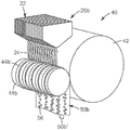
도 1은 본 명세서에서 설명된 바와 같은 개구들을 갖는 형성 중합체 층을 제조하기 위한 장치의 개략도이다.
도 2는 도 1의 단면선 2-2를 따라 취한 본 명세서에서 설명된 바와 같은 개구들을 갖는 형성 중합체 층의 단면도이다.
도 3은 복수의 심(shim), 한 세트의 단부 블록, 구성요소들을 조립하기 위한 볼트, 및 압출될 재료를 위한 입구 피팅(inlet fitting)을 포함하는 도 1의 장치에 사용하기 적합한 한 세트의 압출 다이 요소의 예시적인 실시 형태의 분해 사시도이다.
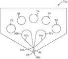
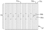
도 4는 도 3의 심들 중 하나의 평면도이다.
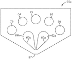
도 5는 도 3의 심들 중 상이한 하나의 평면도이다.
도 6은 도 3의 심들 중 상이한 하나의 평면도이다.
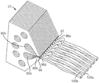
도 7은 중합체 재료를 공급받고 네팅을 형성하는 도 3의 압출 다이의 일부의 개략 사시도이다.
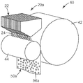
도 7a는 닙에 대한 압출 다이의 대안적인 배열의 개략 사시도이다.
도 7b는 대안적인 닙 롤의 개략 사시도이다.
도 8은 실시예들의 일부에서 사용되는 압출 다이의 분배 표면의 확대 정면도이다.
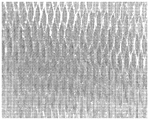
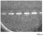
도 9는 실시예 1의 개구들을 갖는 중합체 층의 광학 디지털 사진이다.
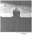
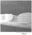
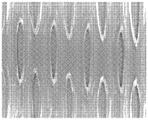
도 10은 도 9에 도시된 개구들을 갖는 중합체 층의 구멍들 중 하나의 단면의 주사 전자 디지털 현미경사진이다.
도 11은 실시예 2의 개구들을 갖는 중합체 층의 광학 디지털 사진이다.
도 12는 도 11에 도시된 개구들을 갖는 중합체 층의 구멍들 중 하나의 단면의 주사 전자 디지털 현미경사진이다.
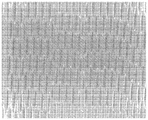
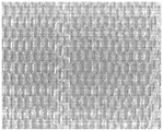
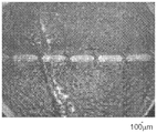
도 13은 실시예 3의 개구들을 갖는 중합체 층의 광학 디지털 사진이다.
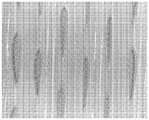
도 14는 도 13에 도시된 개구들을 갖는 중합체 층의 구멍들 중 하나의 단면의 주사 전자 디지털 현미경사진이다.
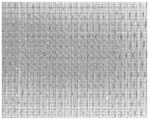
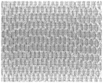
도 15는 실시예 4의 개구들을 갖는 중합체 층의 광학 디지털 사진이다.
도 16은 도 15에 도시된 개구들을 갖는 중합체 층의 구멍들 중 하나의 단면의 주사 전자 디지털 현미경사진이다.
도 17은 실시예 5의 개구들을 갖는 중합체 층의 광학 디지털 사진이다.
도 18은 도 17에 도시된 개구들을 갖는 중합체 층의 구멍들 중 하나의 단면의 주사 전자 디지털 현미경사진이다.
도 19는 실시예 6의 개구들을 갖는 중합체 층의 광학 디지털 사진이다.
도 20은 도 19에 도시된 개구들을 갖는 중합체 층의 구멍들 중 하나의 단면의 주사 전자 디지털 현미경사진이다.
도 21은 실시예들의 일부에서 사용되는 압출 다이의 분배 표면의 확대 정면도이다.
도 22는 실시예 7의 개구들을 갖는 중합체 층의 광학 디지털 사진이다.
도 23은 도 22에 도시된 개구들을 갖는 중합체 층의 구멍들 중 하나의 단면의 주사 전자 디지털 현미경사진이다.
도 24는 실시예들의 일부에서 사용되는 압출 다이의 분배 표면의 확대 정면도이다.
도 25는 실시예 8의 개구들을 갖는 중합체 층의 광학 디지털 사진이다.
도 26은 도 22에 도시된 개구들을 갖는 중합체 층의 구멍들 중 하나의 단면의 주사 전자 디지털 현미경사진이다.
도 27은 실시예 9의 개구들을 갖는 중합체 층의 광학 디지털 사진이다.
도 28은 도 27에 도시된 개구들을 갖는 중합체 층의 구멍들 중 하나의 단면의 주사 전자 디지털 현미경사진이다.
도 29는 실시예 10에서 사용되는 압출 다이의 분배 표면의 확대 정면도이다.
도 30은 실시예 10의 개구들을 갖는 중합체 층의 광학 디지털 사진이다.BRIEF DESCRIPTION OF THE DRAWINGS Figure 1 is a schematic diagram of an apparatus for producing a forming polymer layer having apertures as described herein.
2 is a cross-sectional view of a forming polymer layer having openings as described herein taken along section line 2-2 of Fig.
Fig. 3 shows a set of one suitable for use in the device of Fig. 1 including a plurality of shims, a set of end blocks, bolts for assembling the components, and an inlet fitting for the material to be extruded. Lt; / RTI > is an exploded perspective view of an exemplary embodiment of an extrusion die element.
4 is a plan view of one of the shims of Fig.
Figure 5 is a plan view of one of the shims of Figure 3;
Figure 6 is a plan view of one of the shims of Figure 3;
Figure 7 is a schematic perspective view of a portion of the extrusion die of Figure 3 that is fed with polymeric material and forms netting.
7A is a schematic perspective view of an alternative arrangement of the extrusion die for the nip.
Figure 7b is a schematic perspective view of an alternative nip roll.
Figure 8 is an enlarged front view of the dispensing surface of an extrusion die used in some of the embodiments.
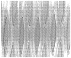
9 is an optical digital photograph of a polymer layer having apertures of Example 1. Fig.
10 is a scanning electron digital micrograph of one of the apertures of the polymer layer with openings shown in Fig.
11 is an optical digital photograph of a polymer layer having openings of Example 2. Fig.
12 is a scanning electron digital micrograph of one of the apertures of the polymer layer with openings shown in Fig.
13 is an optical digital photograph of a polymer layer having openings of Example 3. Fig.
14 is a scanning electron digital micrograph of one of the apertures of the polymer layer with openings shown in Fig.
15 is an optical digital photograph of a polymer layer having apertures of Example 4. Fig.
16 is a scanning electron digital micrograph of one of the apertures of the polymer layer with openings shown in Fig.
17 is an optical digital photograph of a polymer layer having apertures of Example 5. Fig.
18 is a scanning electron digital micrograph of one of the apertures of the polymer layer with openings shown in Fig.
19 is an optical digital photograph of a polymer layer having openings of Example 6;
Figure 20 is a scanning electron digital micrograph of one of the apertures of the polymer layer with openings shown in Figure 19;
Figure 21 is an enlarged front view of the dispensing surface of an extrusion die used in some of the embodiments.
22 is an optical digital photograph of a polymer layer having apertures of Example 7. Fig.
Figure 23 is a scanning electron digital micrograph of one of the apertures of the polymer layer with openings shown in Figure 22;
24 is an enlarged front view of the dispensing surface of the extrusion die used in some of the embodiments.
25 is an optical digital photograph of a polymer layer having apertures of Example 8;
Figure 26 is a scanning electron digital micrograph of one of the apertures of the polymer layer with openings shown in Figure 22;
27 is an optical digital photograph of a polymer layer having apertures of Example 9. Fig.
28 is a scanning electron digital micrograph of one of the apertures of the polymer layer with openings shown in Fig.
29 is an enlarged front view of the distribution surface of the extrusion die used in Example 10. Fig.
30 is an optical digital photograph of a polymer layer having apertures of Example 10. Fig.
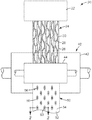
도 1을 참조하면, 개구들을 갖는 중합체 층을 제조하기 위한 예시적인 장치(20)가 도시된다. 장치(20)는 접합 영역(30)에서 함께 결합된 제1 스트랜드(26) 및 제2 스트랜드(28)를 포함하는 중합체 네팅(24)을 압출하는 압출기(22)를 갖는다. 본 기술 분야에서 공지된 것들(예를 들어, 미국 특허 제4,038,008호(라센(Larsen)) 참조)을 포함하여, 어레이 전체를 통하여 접합 영역에서 주기적으로 함께 결합된 중합체 스트랜드들의 어레이를 포함하는 다양한 네팅들 중 임의의 것이 사용될 수 있다. 유용한 중합체 네팅은 또한, 개시 내용이 본 명세서에 참고로 인용된, 2011년 8월 22일자로 출원된 미국 특허 출원 제61/526,001호 및 2011년 9월 2일자로 출원된 미국 특허 출원 제61/530,521호를 갖는 공계류 중인 출원에 설명되어 있다.Referring to Figure 1, an
도시된 바와 같이, 중합체 네팅(24)은 닙(40) 내로 수직으로 압출된다. 닙(40)은 백업 롤(42) 및 닙 롤(44)을 포함한다. 일부 실시 형태에서, 백업 롤(42)은 매끄러운 크롬 도금된 강재 롤이고, 닙 롤(44)은 실리콘 고무 롤이다. 일부 실시 형태에서, 백업 롤(42) 및 닙 롤(44) 둘 모두는, 예를 들어, 내부 수류에 의해 온도가 제어된다.As shown, the polymer netting 24 is extruded vertically into the
일부 실시 형태에서, 여기서 도시된 하나를 예로 들면, 중합체 네팅(24)은 닙(40) 내로 직접 지나가고, 닙(40)은 급랭 닙이다. 그러나, 이는 필요한 것으로 여겨지지는 않으며, 네팅의 압출 및 닙 내로의 유입은 즉각 순차적일 필요는 없다.In some embodiments, as one example shown here, the polymer netting 24 passes directly into the
닙(40) 통과 후, 중합체 네팅(24)은 개구들을 갖는 중합체 층(50)으로 변하게 된다. 일부 실시 형태에서, 중합체 층(50)이 백업 롤(42) 둘레를 그의 원주의 적어도 일부에 대해 둘러싸고 있도록 하는 것이 유리할 수 있다. 중합체 층(50)은 관찰자를 향하는 측의 제1 주 표면(52) 및 관찰자로부터 반대 측의 제2 주 표면(54)을 갖는다. 다수의 개구들(56)은 중합체 층(50)을 제1 주 표면(52)으로부터 제2 주 표면(54)으로 통과한다. 일부 실시 형태에서, 개구들(56)은 적격으로 형성된 매끈한 에지(58)를 갖는다. 더욱이, 일부 실시 형태에서, 개구들(56)은 개구(56)가 중합체 층(50)의 내부 어딘가에서 최소 면적(60)을 갖도록 제1 주 표면(52) 및 제2 주 표면(54) 둘 모두로부터 내향으로 테이퍼진다.After passing through the
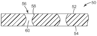
개구들(56)의 이러한 특징부는 도 1의 단면선 2-2를 따라 취한 중합체 층(50)의 단면도인 도 2에서 잘 이해될 수 있다. 여기서, 개구들(56)은 적격으로 형성된 매끈한 에지(58)를 갖는다는 것을 알 수 있다. 개구들(56)은 제1 주 표면(52) 및 제2 주 표면(54) 둘 모두로부터 내향으로 테이퍼진다. 개구(56)가 최소 면적(60)으로 테이퍼지는 지점은 중합체 층(50)의 내부에 있는 것으로 도시된다. 일부 실시 형태에서, 개별 개구들(56)은 0.005 ㎟ 내지 5 ㎟의 범위에 있고, 더욱이, 적어도 대다수의 개구들(56)에 대해, 최소 면적은 어느 주 표면(52 또는 54)에도 없다.This feature of the
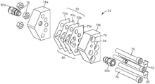
앞서 논의된 바와 같이, 다양한 기술들 중 어느 하나에 의해 제조된 다양한 유형의 네팅이 본 명세서에서 설명된 바와 같이 개구들을 갖는 중합체 층을 제조하는 것과 관련하여 사용될 수 있다. 그러나, 아래에서 열거되는 실시예들을 제조하기 위하여 채용되었던 압출기(22)는 보다 상세하게 설명될 것이다. 도 3을 참조하면, 예시적인 압출 다이(22)의 분해도가 예시되어 있다. 압출 다이(22)는 복수의 심들(70)을 포함한다. 본 명세서에 기술된 압출 다이의 일부 실시 형태에서는, 2개의 단부 블록들(예를 들어, 74a, 74b) 사이에서 압착되는, 다양한 유형(예를 들어, 심들(70a, 70b, 70c))의 다수의 매우 얇은 심들(40)(전형적으로 수천 개의 심들; 일부 실시 형태에서는, 적어도 1000, 2000, 3000, 4000, 5000, 6000, 7000, 8000, 9000, 또는 심지어 10,000개)이 있을 것이다. 편리하게는, 체결구(예컨대, 너트(78) 상에 나사체결되는 관통 볼트(76))가 관통 구멍(79)을 통과함으로써 압출 다이(22)를 위한 구성요소를 조립하기 위해 사용된다. 입구 피팅(80a, 80b)이 압출될 재료를 압출 다이(22) 내로 도입하기 위해 각각 단부 블록(74a, 74b) 상에 제공된다. 일부 실시 형태에서, 입구 피팅(80a, 80b)은 종래 유형의 용융 트레인(melt train)에 연결된다. 일부 실시 형태에서, 카트리지 히터(82)가 압출될 재료를 다이 내에 있는 동안 바람직한 온도로 유지시키기 위해 압출 다이(22) 내의 리셉터클(84) 내로 삽입된다.As discussed above, various types of netting produced by any one of a variety of techniques may be used in connection with fabricating polymeric layers having apertures as described herein. However, the
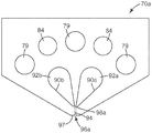
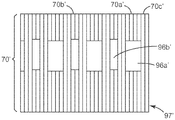
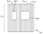
이제 도 4를 참조하면, 도 3으로부터의 심(70a)의 평면도가 예시된다. 심(70a)은 제1 개구부(90a) 및 제2 개구부(90b)를 구비한다. 압출 다이(22)가 조립될 때, 심들(70) 내의 제1 개구부들(90a)은 함께 제1 공동(92a)의 적어도 일부를 한정한다. 유사하게, 심들(70) 내의 제2 개구부들(90b)은 함께 제2 공동(92b)의 적어도 일부를 한정한다. 압출될 재료가 편리하게는 입구 포트(80a)를 통해 제1 공동(92a)으로 들어가는 한편, 압출될 재료가 편리하게는 입구 포트(80b)를 통해 제2 공동(92b)으로 들어간다. 심(70a)은 분배 표면(97) 내의 제1 분배 오리피스(96a)에서 종단되는 덕트(94)를 갖는다. 심(70a)은 제1 공동(92a)과 덕트(94) 사이에 도관을 제공하는 통로(98a)를 추가로 갖는다. 덕트(94)의 치수 및 특히 제1 분배 오리피스(96a)의 그 단부에서의 치수는, 그들로부터 압출된 중합체 스트랜드에서 원하는 치수들에 의해 제한된다. 제1 분배 오리피스(96a)로부터 나오는 스트랜드의 스트랜드 속도가 또한 중요하기 때문에, 공동(92a) 내의 압력과 통로(98a)의 치수의 조작이 원하는 스트랜드 속도를 설정하기 위해 사용될 수 있다.Referring now to FIG. 4, a top view of
이제 도 5를 참조하면, 심(70b)은 제2 공동(92b)과 제2 분배 오리피스(96) 사이에 도관을 제공하는 대신에 통로를 갖춘, 심(70a)의 반영(reflection)이다.5, the
이제 도 6을 참조하면, 도 3으로부터의 심(70c)의 평면도가 예시된다. 심(70c)은 각각 제1 또는 제2 공동들(92a, 92b) 사이에 통로를 구비하지 않고, 분배 표면(97) 상으로 개방된 덕트를 갖지 않는다.Referring now to FIG. 6, a top view of the
이제 도 7을 참조하면, 중합체 재료를 공급받고 네트를 형성하는, 압출 다이(22)의 일부의 개략 사시도가 예시된다. 제1 공동(92a)으로부터의 중합체가 제1 분배 오리피스(96a)로부터 제1 스트랜드(100a)로서 나오고, 제2 스트랜드(100b)가 제2 분배 오리피스(96b)로부터 나온다. 통로(98a)(이 도면에서 가장 가까운 심 뒤에 숨겨짐)와 통로(98b), 및 공동(92a, 92b) 내의 압력은 제1 스트랜드(100a)의 스트랜드 속도가 제2 스트랜드(100b)의 스트랜드 속도보다 약 2배 내지 6배 더 크도록 전형적으로 선택된다. 개시 내용이 본 명세서에 참고로 인용된 2011년 8월 22일자로 출원된 미국 특허 출원 제61/526,001호를 갖는 공계류 중인 출원에 더 충분히 설명된 바와 같이, 이는 중합체 네팅(24)이 형성되도록 한다.Referring now to FIG. 7, a schematic perspective view of a portion of an extrusion die 22 that receives polymeric material and forms a net is illustrated. The polymer from the
이제 도 7a를 참조하면, 닙(40)에 대한 압출 다이(22)의 상이한 배열을 갖는 다른 예시적인 장치(20a)의 개략 사시도가 도시되어 있다. 대안적인 장치(20a)에서, 압출 다이(22)는 중합체 네팅(24)이 닙 롤러(44) 상으로 분배되고 그 롤러 상에 그리고 닙 롤러(44)와 백업 롤러(42) 사이의 닙 내로 이동되도록 위치된다. 압출 다이(22)를 닙 롤러(44)에 상당히 가까이 위치시킴으로써, 중합체 네팅(24)을 이루는 스트랜드가 중력 하에서 처지고 연장될 시간이 없게 된다. 이러한 위치 설정에 의해 제공되는 이점은 중합체 층(50a) 내의 개구들(56a)이 더 둥글게 되는 경향이 있다는 것이다. 더욱이, 이는 닙(40)을 형성하는 롤들 중 하나에 매우 가까이에 뿐만 아니라 그 롤의 원주 속도와 유사한 압출 속도로 압출함으로써 달성될 수 있다.Referring now to Figure 7a, a schematic perspective view of another
이제 도 7b를 참조하면, 대안적인 닙 롤(44b)을 갖는 다른 예시적인 장치(20b)의 개략 사시도가 도시되어 있다. 대안적인 닙 롤(44b)의 표면은 상승된 영역(44b')을 포함하고, 이는 닙 롤(44b)의 다른 영역들보다 백업 롤(42)에 대항하는 중합체 네팅(24) 상에 더 큰 닙핑 힘(nipping force)을 인가한다. 도시된 실시 형태에서, 잠재적 개구들이 닙(40) 내에서 압착되어 완전히 폐쇄된 중실 층의 종방향 밴드(50b')에 의해 중합체 층(50b) 내의 개구들(56)이 분리되기에 충분한 힘이 상승된 영역(44b')에 의해 인가되었다. 상승된 영역 대신, 닙을 구성하는 롤들의 하나 또는 둘 모두가 상이한 온도의 구역들을 가질 수 있어서, 상이한 크기의 개구들 또는 개구들이 없는 종방향 밴드가 생길 수 있게 할 수 있다. 더욱이, 압출된 중합체 네팅의 상대 두께는 구멍 크기의 범위에 영향을 주는 것으로 알려져 있는데, 비교적 두꺼운 네팅의 경우, 중실 필름의 종방향 밴드(50b')를 형성하도록 용융물을 닙핑하는 것이 용이하다. 일부 실시 형태에서, 개구의 단면의 형상에 영향을 주도록, 필름의 일 측을 타 측보다 빠른 속도로 급랭하는 것이 요구될 수 있다.Referring now to Fig. 7b, a schematic perspective view of another
일부 실시 형태에서, 층의 일 측 또는 양 측을 패턴화하는 것이 바람직할 수 있다. 이는, 예를 들어, 닙 롤러(44) 및 백업 롤러(42) 중 하나 또는 둘 모두의 표면의 패턴화를 이용하여 달성될 수 있다. 패턴화된 롤들의 사용이 중합체를 교차 방향 또는 다운웨브(downweb) 방향으로 우선적으로 이동시킬 수 있다는 것은 중합체 후크(hook) 형성 분야에서 알려져 있다. 이러한 개념은 층의 일 측 또는 양 측 상에 구멍을 형상화하기 위하여 이용될 수 있다.In some embodiments, it may be desirable to pattern one or both sides of the layer. This can be achieved, for example, by using the patterning of the surface of one or both of the
네팅을 제조할 수 있는 예시적인 중합체 재료는 폴리올레핀(예를 들어, 폴리프로필렌 및 폴리에틸렌), 폴리비닐 클로라이드, 폴리스티렌, 나일론, 폴리에스테르(예를 들어, 폴리에틸렌 테레프탈레이트) 및 이들의 공중합체 및 블렌드를 포함하는 열가소성 수지; 탄성중합체 재료(예를 들어, ABA 블록 공중합체, 폴리우레탄, 폴리올레핀 탄성중합체, 폴리우레탄 탄성중합체, 메탈로센 폴리올레핀 탄성중합체, 폴리아미드 탄성중합체, 에틸렌 비닐 아세테이트 탄성중합체, 및 폴리에스테르 탄성중합체); 접착제, 예컨대 아크릴레이트 공중합체 감압 접착제, 고무 기반 접착제(예를 들어, 천연 고무, 폴리아이소부틸렌, 폴리부타디엔, 부틸 고무, 및 스티렌 블록 공중합체 고무에 기반하는 것들), 실리콘 폴리우레아 또는 실리콘 폴리옥사아미드 기반 접착제, 폴리우레탄 유형 접착제, 및 폴리(비닐 에틸 에테르), 및 이들의 공중합체 또는 블렌드를 포함한다. 다른 바람직한 재료는 예를 들어 스티렌-아크릴로니트릴, 셀룰로오스 아세테이트 부티레이트, 셀룰로오스 아세테이트 프로피오네이트, 셀룰로오스 트라이아세테이트, 폴리에테르 설폰, 폴리메틸 메타크릴레이트, 폴리우레탄, 폴리에스테르, 폴리카르보네이트, 폴리비닐 클로라이드, 폴리스티렌, 폴리에틸렌 나프탈레이트, 나프탈렌 다이카르복실산 기반 공중합체 또는 블렌드, 폴리올레핀, 폴리이미드, 이들의 혼합물 및/또는 조합을 포함한다.Exemplary polymeric materials from which netting can be made include polyolefins (e.g., polypropylene and polyethylene), polyvinyl chloride, polystyrene, nylon, polyesters (e.g., polyethylene terephthalate), and copolymers and blends thereof Containing thermoplastic resin; Elastomeric materials (e.g., ABA block copolymers, polyurethanes, polyolefin elastomers, polyurethane elastomers, metallocene polyolefin elastomers, polyamide elastomers, ethylene vinyl acetate elastomers, and polyester elastomers); Adhesives such as acrylate copolymer pressure sensitive adhesives, rubber based adhesives (e.g. based on natural rubber, polyisobutylene, polybutadiene, butyl rubber, and styrene block copolymer rubbers), silicone polyurea or silicone poly Oxamide based adhesives, polyurethane type adhesives, and poly (vinyl ethyl ether), and copolymers or blends thereof. Other preferred materials include, for example, styrene-acrylonitrile, cellulose acetate butyrate, cellulose acetate propionate, cellulose triacetate, polyethersulfone, polymethylmethacrylate, polyurethane, polyester, polycarbonate, polyvinyl Chloride, polystyrene, polyethylene naphthalate, naphthalene dicarboxylic acid-based copolymers or blends, polyolefins, polyimides, mixtures and / or combinations thereof.
일부 실시 형태에서, 본 명세서에서 설명되는 중합체 층을 제조하기 위해 사용된 네팅은 교호하는 제1 및 제2 중합체 스트랜드를 포함하고, 제2 중합체 스트랜드는 상이한 제2 중합체를 포함한다.In some embodiments, the netting used to make the polymer layer described herein comprises alternating first and second polymeric strands and the second polymeric strand comprises a different second polymer.
일부 실시예에서, 본 명세서에 기술된 중합체 층을 제조하기 위해 사용되는 네팅의 중합체 재료는 기능적(예컨대, 광학 효과) 및/또는 미적 목적(예컨대, 각각이 상이한 색상/음영을 가짐)을 위한 착색제(예컨대, 안료 및/또는 염료)를 포함한다. 적합한 착색제는 다양한 중합체 재료에 사용되는 당업계에 알려진 것이다. 착색제에 의해 부여되는 예시적인 색상은 백색, 흑색, 적색, 분홍색, 주황색, 황색, 녹색, 청록색, 자주색 및 청색을 포함한다. 일부 실시 형태에서, 하나 이상의 중합체 재료에 대해 일정 정도의 불투명도를 갖는 것이 바람직한 수준이다. 특정 실시 형태에 사용될 착색제(들)의 양은 (예컨대, 원하는 색상, 색조, 불투명도, 투과율 등을 달성하기 위해) 당업자에 의해 쉽게 결정될 수 있다. 원한다면, 중합체 재료는 동일하거나 상이한 색상을 갖도록 제형화될 수 있다. 유색 스트랜드들이 비교적 미세한(예컨대, 50 마이크로미터 미만의) 직경을 가질 때, 웨브의 외양은 실크를 연상시키는 미광(shimmer)을 가질 수 있다.In some embodiments, the polymeric material of the netting used to make the polymer layer described herein may be a colorant for functional (e.g., optical effect) and / or aesthetic (e.g., each having a different color / shade) (E.g., pigments and / or dyes). Suitable colorants are those known in the art for use in various polymeric materials. Exemplary colors imparted by the colorant include white, black, red, pink, orange, yellow, green, cyan, purple and blue. In some embodiments, it is desirable to have a degree of opacity for one or more polymeric materials. The amount of colorant (s) to be used in a particular embodiment can be readily determined by one of ordinary skill in the art (e.g., to achieve the desired hue, hue, opacity, transmissivity, etc.). If desired, the polymeric material may be formulated to have the same or a different color. When the colored strands have a relatively fine diameter (e.g., less than 50 micrometers), the appearance of the web may have a shimmer that reminds of silk.
일부 실시 형태에서, 중합체 스트랜드들은 평균 폭이 10 마이크로미터 내지 500 마이크로미터(10 마이크로미터 내지 400 마이크로미터 또는 심지어 10 마이크로미터 내지 250 마이크로미터)의 범위에 있다.In some embodiments, the polymeric strands range in average width from 10 micrometers to 500 micrometers (10 micrometers to 400 micrometers, or even 10 micrometers to 250 micrometers).
일부 실시 형태에서, 본 명세서에 기술된 중합체 층을 제조하기 위해 사용되는 네팅은 평량이 5 g/m2 내지 400 g/m2(일부 실시 형태에서, 10 g/m2 내지 200 g/m2)의 범위에 있다.In some embodiments, the netting used to make the polymer layer described herein has a basis weight between 5 g / m 2 and 400 g / m 2 (in some embodiments between 10 g / m 2 and 200 g / m 2 ). ≪ / RTI >
일부 실시 형태에서, 본 명세서에 기술된 중합체 층을 제조하기 위해 사용되는 네팅은 스트랜드 피치가 0.5 mm 내지 20 mm(일부 실시 형태에서, 0.5 mm 내지 10 mm)의 범위에 있다.In some embodiments, the netting used to make the polymer layer described herein has a strand pitch in the range of 0.5 mm to 20 mm (in some embodiments, 0.5 mm to 10 mm).
일부 실시 형태에서, 본 명세서에 기술된 중합체 층을 제조하기 위해 사용되는 네팅의 스트랜드들은 실질적으로 서로 (즉, 개수로 적어도 50(적어도 55, 60, 65, 70, 75, 80, 85, 90, 95, 99, 또는 심지어 100)퍼센트가) 교차하지 않는다.In some embodiments, the strands of netting used to make the polymer layers described herein are substantially (i.e., in number of at least 50 (at least 55, 60, 65, 70, 75, 80, 85, 90, 95, 99, or even 100 percent) do not cross.
일부 실시 형태에서, 본 명세서에 기술된 중합체 층을 제조하기 위해 사용되는 네팅은 다이아몬드 형상 또는 6각형 형상의 개구들 중 적어도 하나를 나타내는 교호하는 제1 및 제2 중합체 스트랜드를 갖는다.In some embodiments, the netting used to make the polymer layer described herein has alternating first and second polymeric strands representing at least one of diamond-like or hexagonal shaped openings.
일부 실시 형태에서, 본 명세서에 기술된 중합체 층을 제조하기 위해 사용되는 네팅의 중합체 스트랜드는 평균 폭이 10 마이크로미터 내지 500 마이크로미터(10 마이크로미터 내지 400 마이크로미터, 또는 심지어 10 마이크로미터 내지 250 마이크로미터)의 범위에 있다.In some embodiments, the polymeric strands of netting used to make the polymeric layers described herein have an average width of 10 micrometers to 500 micrometers (10 micrometers to 400 micrometers, or even 10 micrometers to 250 micrometers Meter).
일부 실시 형태에서, 본 명세서에 기술된 중합체 층을 제조하기 위해 사용되는 네팅의 중합체 스트랜드는 탄성을 갖는다.In some embodiments, the polymeric strands of netting used to make the polymeric layers described herein have elasticity.
일부 실시 형태에서, 본 명세서에 기술된 중합체 층을 제조하기 위해 사용되는 네팅은 친수성 재료로 제조되거나 또는 그로 코팅되어 흡수성을 갖게 한다. 일부 실시 형태에서, 본 명세서에 기술된 네팅들은 환부로부터의 과도한 삼출물을 제거하기 위한 환부 흡수재로서 유용하고, 일부 실시 형태에서, 본 명세서에 기술된 네팅들은 생체흡수성 중합체로 제조된다.In some embodiments, the netting used to make the polymer layer described herein is made of, or coated with, a hydrophilic material to make it absorbent. In some embodiments, the nettings described herein are useful as a localized absorbent material to remove excess exudates from the affected area, and in some embodiments, the nettings described herein are made of a bioabsorbable polymer.
본 명세서에 기술된 중합체 층은, 예를 들어, 중합체 스트랜드들의 어레이를 포함하는 네팅을 닙에 통과시키는 단계 또는 캘린더링하는 단계 중 적어도 하나에 의해 제조될 수 있는데, 중합체 스트랜드들은 어레이 전체에 걸쳐 접합 영역에서 주기적으로 함께 결합되어 있다.The polymeric layers described herein can be produced, for example, by at least one of passing a netting comprising an array of polymeric strands into the nip or calendering, wherein the polymeric strands are bonded Are periodically joined together in the region.
본 명세서에 기술된 중합체 층의 형성 시, 용융물의 온도 및 급랭 온도와, 용융물의 두께가 구멍의 크기에 영향을 미치는 것이 관찰되었다. 용융 온도가 높으면 닙 내의 중합체의 더 큰 이동을 허용하여 더 작은 구멍 크기를 생성하는 경향이 있다. 저온 급랭은 중합체 이동의 양을 제한하는 것으로 나타나서 더 큰 구멍 크기를 생성한다.It has been observed that upon formation of the polymer layer described herein, the temperature of the melt and the quench temperature and the thickness of the melt affect the size of the pores. Higher melt temperatures tend to allow for greater movement of the polymer within the nip to produce smaller pore sizes. Cold quenching appears to limit the amount of polymer movement, resulting in larger pore sizes.
일부 실시 형태에서, 본 명세서에 기술된 중합체 층은 대체로 대향하는 제1 및 제2 주 표면의 각각에 대한 전체 개방 면적이 각각의 주 표면의 전체 면적의 50퍼센트 이하(일부 실시 형태에서, 45, 40, 35, 30, 25, 20, 15, 10, 5, 4 3, 2, 1, 0.75, 0.5, 0.25, 또는 심지어 0.1퍼센트 이하)이다. 일부 실시 형태에서, 적어도 대다수의 개구들에 있어서, 각각의 개구의 면적은 5 ㎟ 이하(일부 실시 형태에서, 2.5, 2, 1, 0.5, 0.1, 0.05, 0.01, 0.075, 또는 심지어 0.005 ㎟ 이하)이다.In some embodiments, the polymeric layer described herein has a total open area for each of the generally opposite first and second major surfaces of less than or equal to 50 percent of the total area of each major surface (in some embodiments, 45, 40, 35, 30, 25, 20, 15, 10, 5, 4, 3, 2, 1, 0.75, 0.5, 0.25, or even 0.1 percent or less). In some embodiments, for at least a majority of the openings, the area of each opening is less than or equal to 5 mm 2 (in some embodiments, less than 2.5, 2, 1, 0.5, 0.1, 0.05, 0.01, 0.075, or even 0.005 mm 2) to be.
일부 실시 형태에서, 본 명세서에 기술된 중합체 층은 50,000 내지 6,000,000 (일부 실시 형태에서, 100,000 내지 6,000,000, 500,000 내지 6,000,000, 또는 심지어 1,000,000 내지 6,000,000)개의 개구/m2의 범위를 갖는다.In some embodiments, the polymer layer described herein has a range of 50,000 to 6,000,000 (in some embodiments, 100,000 to 6,000,000, 500,000 to 6,000,000, or even 1,000,000 to 6,000,000) openings / m 2 .
일부 실시 형태에서, 본 명세서에 기술된 중합체 층에 대해, 개구들은 5 마이크로미터 내지 1 mm(일부 실시 형태에서, 10 마이크로미터 내지 0.5 mm)의 범위의 폭을 갖는다. 일부 실시 형태에서, 본 명세서에 기술된 중합체 층에 대해, 개구들은 길이가 100 마이크로미터 내지 10 mm(일부 실시 형태에서, 100 마이크로미터 내지 1 mm)의 범위에 있다. 일부 실시 형태에서, 본 명세서에 기술된 중합체 층에 대해, 개구들은 길이 대 폭 비가 1:1 내지 100:1(일부 실시 형태에서, 1:1 내지 1.9:1, 2:1 내지 100:1, 2:1 내지 75:1, 2:1 내지 50:1, 2:1 내지 25:1, 또는 심지어 2:1 내지 10:1)의 범위에 있다.In some embodiments, for the polymer layer described herein, the openings have a width in the range of 5 micrometers to 1 mm (in some embodiments, 10 micrometers to 0.5 mm). In some embodiments, for the polymer layer described herein, openings are in the range of 100 micrometers to 10 mm in length (in some embodiments, 100 micrometers to 1 mm). In some embodiments, for the polymer layer described herein, the openings may have a length to width ratio of from 1: 1 to 100: 1 (in some embodiments, from 1: 1 to 1.9: 1, from 2: 1 to 100: 2: 1 to 75: 1, 2: 1 to 50: 1, 2: 1 to 25: 1, or even 2: 1 to 10: 1).
일부 실시 형태에서, 개구들은 적어도 2개의 뾰족한 단부(pointed end)를 갖는다. 일부 실시 형태에서, 개구들의 적어도 일부는 2개의 뾰족한 단부를 갖는 세장형이다. 일부 실시 형태에서, 개구들의 적어도 일부는 2개의 대향하는 뾰족한 단부를 갖는 세장형이다. 일부 실시 형태에서, 개구들의 적어도 일부는 타원형이다.In some embodiments, the openings have at least two pointed ends. In some embodiments, at least a portion of the openings are elongated with two pointed ends. In some embodiments, at least a portion of the openings are elongate with two opposing tapered ends. In some embodiments, at least a portion of the apertures are elliptical.
일부 실시 형태에서, 본 명세서에 기술된 중합체 층은 두께가 최대 2 mm이다(일부 실시 형태에서, 최대 1 mm, 500 마이크로미터, 250 마이크로미터, 100 마이크로미터, 75 마이크로미터, 50 마이크로미터, 또는 심지어 최대 25 마이크로미터이고; 10 마이크로미터 내지 750 마이크로미터, 10 마이크로미터 내지 750 마이크로미터, 10 마이크로미터 내지 500 마이크로미터, 10 마이크로미터 내지 250 마이크로미터, 10 마이크로미터 내지 100 마이크로미터, 10 마이크로미터 내지 75 마이크로미터, 10 마이크로미터 내지 50 마이크로미터, 또는 심지어 10 마이크로미터 내지 25 마이크로미터의 범위에 있다). 일부 실시 형태에서, 본 명세서에 기술된 중합체 층은 평균 두께 250 마이크로미터 내지 5 mm 범위의 시트이다. 일부 실시 형태에서, 본 명세서에 기술된 중합체 층은 평균 두께가 5 mm 이하인 필름이다.In some embodiments, the polymer layer described herein has a thickness of up to 2 mm (in some embodiments, up to 1 mm, 500 micrometers, 250 micrometers, 100 micrometers, 75 micrometers, 50 micrometers, or 10 micrometers to 750 micrometers, 10 micrometers to 500 micrometers, 10 micrometers to 250 micrometers, 10 micrometers to 100 micrometers, 10 micrometers To 75 micrometers, 10 micrometers to 50 micrometers, or even 10 micrometers to 25 micrometers). In some embodiments, the polymer layer described herein is a sheet having an average thickness in the range of 250 micrometers to 5 mm. In some embodiments, the polymer layer described herein is a film having an average thickness of 5 mm or less.
일부 실시 형태에서, 본 명세서에 기술된 중합체 층에 대해, 개구들의 적어도 일부는 제1 중합체 재료를 포함하는 제1 주 표면 상의 제1 측면 및 상이한 제2 중합체 재료를 포함하는 제1 주 표면 상의 대향하는 제2 측면을 갖는다. 일부 실시 형태에서, 제1 또는 제2 중합체 재료 중 적어도 하나는 열가소성재(예를 들어, 나일론, 폴리에스테르, 폴리올레핀, 폴리우레탄, 탄성중합체(예를 들어, 스티렌 블록 공중합체), 및 이들의 블렌드)이다.In some embodiments, for the polymeric layer described herein, at least a portion of the apertures are formed from a first side on a first major surface comprising a first polymeric material and a second side opposite to a first major surface comprising a different second polymeric material As shown in Fig. In some embodiments, at least one of the first or second polymeric materials comprises a thermoplastic material (e.g., nylon, polyester, polyolefin, polyurethane, elastomeric (e.g., styrene block copolymer) )to be.
일부 실시 형태에서, 본 명세서에 기술된 중합체 층은 평량이 25 g/m2 내지 500 g/m2(일부 실시 형태에서, 50 g/m2 내지 250 g/m2)의 범위에 있다.In some embodiments, the polymer layer described herein is in the range of a basis weight of from 25 g / m 2 to 500 g / m 2 (in some embodiments, from 50 g / m 2 to 250 g / m 2 ).
본 명세서에서 기술되는 중합체 층은, 예를 들어, 기저귀 및 여성 위생 제품과 같은 개인용 케어 의류에서 구성요소로서 유용하다. 이는 또한 필터링(액체 필터링 포함) 및 음향 제품에 유용할 수 있다.The polymer layers described herein are useful as components in personal care garments, such as, for example, diapers and feminine hygiene products. It can also be useful for filtering (including liquid filtration) and acoustic products.
예시적인 실시양태Exemplary embodiments
1A. 대체로 대향하는 제1 및 제2 주 표면을 가지며 제1 주 표면과 제2 주 표면 사이에서 연장된 개구들의 어레이를 포함하는 중합체 층으로서, 개구들 각각은 제1 및 제2 주 표면으로부터 개구들을 통한 일련의 면적들이 최소 면적 내지 최대 면적의 범위이고, 제1 및 제2 주 표면의 각각에 대해 전체 면적 및 전체 개방 면적이 있고, 제1 및 제2 주 표면의 각각에 대한 전체 개방 면적은 각각의 주 표면의 전체 면적의 50퍼센트 이하이고(일부 실시 형태에서, 45, 40, 35, 30, 25, 20, 15, 10, 5, 4, 3, 2, 1, 0.75, 0.5, 0.25, 또는 심지어 0.1퍼센트 이하이고), 적어도 대다수의 개구들에 있어서, 어느 주 표면에도 최소 면적이 없는, 중합체 층.1A. A polymer layer having an array of openings extending generally between opposing first and second major surfaces and extending between a first major surface and a second major surface, each of the openings extending from the first and second major surfaces The total area of open area for each of the first and second major surfaces is less than the total open area for each of the first and second major surfaces, (In some embodiments, 45, 40, 35, 30, 25, 20, 15, 10, 5, 4, 3, 2, 1, 0.75, 0.5, 0.25, 0.1 percent or less), and at least for a majority of the openings, there is no minimum area on any major surface.
2A. 제1 및 제2 주 표면의 각각에 대한 전체 개방 면적은 각각의 주 표면의 전체 면적의 0.1퍼센트 내지 50퍼센트 이하(일부 실시 형태에서, 0.1퍼센트 내지 45퍼센트 이하, 0.1퍼센트 내지 40퍼센트 이하, 0.1퍼센트 내지 35퍼센트 이하, 0.1퍼센트 내지 30퍼센트 이하, 0.1퍼센트 내지 25퍼센트 이하, 0.1퍼센트 내지 20퍼센트 이하, 0.1퍼센트 내지 15퍼센트 이하, 0.1퍼센트 내지 10퍼센트 이하, 또는 심지어 0.1퍼센트 내지 5퍼센트 이하)의 범위에 있는, 실시 형태 1A의 중합체 층.2A. The total open area for each of the first and second major surfaces is between 0.1 percent and 50 percent (in some embodiments, less than 0.1 percent to 45 percent, less than 0.1 percent to less than 40 percent, less than 0.1 percent, From about 0.1 percent to about 15 percent, from about 0.1 percent to about 10 percent, or even from about 0.1 percent to about 5 percent) Lt; RTI ID = 0.0 > 1A. ≪ / RTI >
3A. 제1 및 제2 주 표면의 각각에 대한 전체 개방 면적은 각각의 주 표면의 전체 면적의 1퍼센트 이하인, 실시 형태 1A의 중합체 층.3A. The polymeric layer of embodiment 1A, wherein the total open area for each of the first and second major surfaces is no more than 1 percent of the total area of each major surface.
4A. 적어도 대다수의 개구들에 있어서, 각각의 개구의 면적은 5 ㎟ 이하(일부 실시 형태에서, 2.5, 2, 1, 0.5, 0.1, 0.05, 0.01, 0.075, 또는 심지어 0.005 ㎟이하)인, 임의의 전술된 실시 형태 A의 중합체 층.4A. Wherein at least in the majority of the openings the area of each opening is less than or equal to 5 mm 2 (in some embodiments, less than or equal to 2.5, 2, 1, 0.5, 0.1, 0.05, 0.01, 0.075 or even 0.005 mm 2) Lt; RTI ID = 0.0 > A < / RTI >
5A. 개구들은 적어도 2개의 뾰족한 단부를 갖는, 임의의 전술된 실시 형태 A의 중합체 층.5A. The polymeric layer of any of the aforementioned embodiments A, wherein the openings have at least two pointed ends.
6A. 개구들의 적어도 일부는 2개의 뾰족한 단부를 갖는 세장형인, 실시 형태 1A 내지 실시 형태 4A 중 임의의 실시 형태의 중합체 층.6A. The polymeric layer of any of Embodiments 1A through 4A, wherein at least a portion of the openings are elongated with two pointed ends.
7A. 개구들의 적어도 일부는 2개의 대향하는 뾰족한 단부를 갖는 세장형인, 실시 형태 1A 내지 실시 형태 4A 중 임의의 실시 형태의 중합체 층.7A. The polymeric layer of any of Embodiments 1A through 4A, wherein at least a portion of the apertures are elongated with two opposing tapered ends.
8A. 개구들의 적어도 일부는 타원형인, 실시 형태 1A 내지 실시 형태 4A 중 임의의 실시 형태의 중합체 층.8A. The polymer layer of any of Embodiments 1A through 4A, wherein at least a portion of the apertures are elliptical.
9A. 50,000 내지 6,000,000 (일부 실시 형태에서, 100,000 내지 6,000,000, 500,000 내지 6,000,000, 또는 심지어 1,000,000 내지 6,000,000)개의 개구/m2의 범위를 갖는, 임의의 전술된 실시 형태 A의 중합체 층.9A. A polymeric layer of any of the aforementioned embodiments A, wherein the polymeric layer has a range of 50,000 to 6,000,000 (in some embodiments, 100,000 to 6,000,000, 500,000 to 6,000,000, or even 1,000,000 to 6,000,000) openings / m 2 .
10A. 개구들은 길이 및 폭을 갖고, 길이 대 폭의 비가 2:1 내지 100:1(일부 실시 형태에서, 2:1 내지 75:1, 2:1 내지 50:1, 2:1 내지 25:1, 또는 심지어, 2:1 내지 10:1)의 범위에 있는, 임의의 전술된 실시 형태 A의 중합체 층.10A. The apertures have length and width and have a length to width ratio of 2: 1 to 100: 1 (in some embodiments, 2: 1 to 75: 1, 2: 1 to 50: 1, 2: 1 to 25: Or even in the range of from 2: 1 to 10: 1).
11A. 개구들은 길이 및 폭을 갖고, 길이 대 폭의 비가 내지 1:1 내지 1.9:1의 범위에 있는, 실시 형태 1A 내지 실시 형태 9A 중 임의의 실시 형태의 중합체 층.11A. The polymer layer of any of embodiments 1A-9A, wherein the openings have length and width, and the ratio of length to width is in the range of 1: 1 to 1.9: 1.
12A. 개구들은 폭이 5 마이크로미터 내지 1 mm(일부 실시 형태에서, 10 마이크로미터 내지 0.5 mm)의 범위에 있는, 임의의 전술된 실시 형태 A의 중합체 층.12A. The polymeric layer of any of the aforementioned embodiments A, wherein the apertures are in the range of 5 micrometers to 1 mm in width (in some embodiments, 10 micrometers to 0.5 mm).
13A. 개구들은 길이가 100 마이크로미터 내지 10 mm(일부 실시 형태에서, 100 마이크로미터 내지 1 mm)의 범위에 있는, 임의의 전술된 실시 형태 A의 중합체 층.13A. The polymeric layer of any of the aforementioned embodiments A, wherein the openings are in the range of 100 micrometers to 10 mm in length (in some embodiments, 100 micrometers to 1 mm).
14A. 층은 두께가 최대 2 mm인(일부 실시 형태에서, 최대 1 mm, 500 마이크로미터, 250 마이크로미터, 100 마이크로미터, 75 마이크로미터, 50 마이크로미터, 또는 심지어 최대 25 마이크로미터인; 10 마이크로미터 내지 750 마이크로미터, 10 마이크로미터 내지 750 마이크로미터, 10 마이크로미터 내지 500 마이크로미터, 10 마이크로미터 내지 250 마이크로미터, 10 마이크로미터 내지 100 마이크로미터, 10 마이크로미터 내지 75 마이크로미터, 10 마이크로미터 내지 50 마이크로미터, 또는 심지어 10 마이크로미터 내지 25 마이크로미터의 범위에 있는), 임의의 전술된 실시 형태 A의 중합체 층.14A. The layer may be at least 2 mm thick (in some embodiments up to 1 mm, 500 micrometers, 250 micrometers, 100 micrometers, 75 micrometers, 50 micrometers, or even up to 25 micrometers; From 10 micrometers to 750 micrometers, from 10 micrometers to 750 micrometers, from 10 micrometers to 500 micrometers, from 10 micrometers to 250 micrometers, from 10 micrometers to 100 micrometers, from 10 micrometers to 75 micrometers, Meter, or even in the range of 10 micrometers to 25 micrometers).
15A. 중합체 층은 평균 두께 250 마이크로미터 내지 5 mm 범위의 시트인, 실시 형태 1A 내지 실시 형태 13A 중 임의의 실시 형태의 중합체 층.15A. The polymer layer of any of Embodiments 1A through 13A, wherein the polymer layer is a sheet having an average thickness in the range of 250 micrometers to 5 mm.
16A. 중합체 층은 평균 두께가 5 mm 이하의 필름인, 실시 형태 1A 내지 실시 형태 13A 중 임의의 실시 형태의 중합체 층.16A. The polymer layer of any of embodiments 1A-13A, wherein the polymer layer is a film having an average thickness of 5 mm or less.
17A. 개구들의 적어도 일부는 제1 중합체 재료를 포함하는 제1 주 표면 상의 제1 측면 및 상이한 제2 중합체 재료를 포함하는 제1 주 표면 상의 대향하는 제2 측면을 갖는, 임의의 전술된 실시 형태 A의 중합체 층.17A. Wherein at least a portion of the apertures have a first side on a first major surface comprising a first polymeric material and an opposing second side on a first major surface comprising a different second polymeric material, Polymer layer.
18A. 제1 또는 제2 중합체 재료 중 적어도 하나는 열가소성재(예를 들어, 나일론, 폴리에스테르, 폴리올레핀, 폴리우레탄, 탄성중합체(예를 들어, 스티렌 블록 공중합체), 및 이들의 블렌드)인, 실시 형태 17A의 중합체 층.18A. Embodiments in which at least one of the first or second polymeric material is a thermoplastic material (e.g., nylon, polyester, polyolefin, polyurethane, elastomeric (e.g., styrene block copolymer), and blends thereof) Polymer layer of 17A.
19A. 평량이 25 g/m2 내지 500 g/m2(일부 실시 형태에서, 50 g/m2 내지 250 g/m2)의 범위에 있는, 임의의 전술된 실시 형태 A의 중합체 층.19A. The polymeric layer of any of the aforementioned embodiments A, wherein the basis weight is in the range of from 25 g / m 2 to 500 g / m 2 (in some embodiments, from 50 g / m 2 to 250 g / m 2 ).
20A. 염료 또는 안료 중 적어도 하나를 포함하는, 임의의 전술된 실시 형태 A의 중합체 층.20A. A polymer layer of any of the aforementioned embodiments A, wherein the polymer layer comprises at least one of a dye or a pigment.
21A. 접착제 층을 추가로 포함하는, 임의의 전술된 실시 형태 A의 중합체 층.21A. The polymeric layer of any of the preceding embodiments A described above, further comprising an adhesive layer.
22A. 임의의 전술된 실시 형태 A의 중합체 층의 제조 방법으로서, 중합체 스트랜드들의 어레이를 포함하는 네팅을 닙에 통과시키는 단계 또는 캘린더링하는 단계 중 적어도 하나를 포함하고, 중합체 스트랜드들은 어레이 전체에 걸쳐 접합 영역에서 주기적으로 함께 결합되어 있는, 방법.22A. A method of making a polymeric layer of any of the preceding embodiments A comprising at least one of passing a netting comprising an array of polymeric strands to a nip or calendering, In which the cells are periodically joined together.
1B. 대체로 대향하는 제1 및 제2 주 표면을 가지며 제1 주 표면과 제2 주 표면 사이에서 연장된 개구들의 어레이를 포함하는 중합체 층으로서, 개구들 각각은 제1 및 제2 주 표면으로부터 개구들을 통한 일련의 면적들이 최소 면적 내지 최대 면적의 범위이고, 적어도 대다수의 개구들에 있어서, 각각의 개구의 면적은 5 ㎟이하(일부 실시 형태에서 2.5, 2, 1, 0.5, 0.1, 0.05, 0.01, 0.075, 또는 심지어 0.005 ㎟ 이하)이고, 적어도 대다수의 개구들에 있어서, 어느 주 표면에도 최소 면적이 없는, 중합체 층.1B. A polymer layer having an array of openings extending generally between opposing first and second major surfaces and extending between a first major surface and a second major surface, each of the openings extending from the first and second major surfaces A series of areas are in a range of a minimum area to a maximum area and at least for most of the openings the area of each opening is 5
2B. 개구들의 적어도 일부는 적어도 2개의 뾰족한 단부를 갖는, 실시 형태 1B의 중합체 층.2B. The polymeric layer of embodiment 1B, wherein at least a portion of the openings have at least two pointed ends.
3B. 개구들의 적어도 일부는 적어도 2개의 뾰족한 단부를 갖는 세장형인, 실시 형태 1B 또는 실시 형태 2B의 중합체 층.3B. The polymeric layer of Embodiment 1B or Embodiment 2B, wherein at least a portion of the apertures are elongated with at least two pointed ends.
4B. 개구들의 적어도 일부는 2개의 대향하는 뾰족한 단부를 갖는 세장형인, 실시 형태 1B 또는 실시 형태 2B의 중합체 층.4B. The polymer layer of embodiment 1B or embodiment 2B, wherein at least a portion of the openings are elongated with two opposing tapered ends.
5B. 개구들의 적어도 일부는 타원형인, 실시 형태 1B 또는 실시 형태 2B의 중합체 층.5B. The polymeric layer of Embodiment 1B or Embodiment 2B, wherein at least a portion of the apertures are elliptical.
6B. 50,000 내지 6,000,000 (일부 실시 형태에서, 100,000 내지 6,000,000, 500,000 내지 6,000,000, 또는 심지어 1,000,000 내지 6,000,000)개의 개구/m2의 범위를 갖는 임의의 전술된 실시 형태 B의 중합체 층.6B. Any of the polymer layers of Embodiment B described above having a range of 50,000 to 6,000,000 (in some embodiments, 100,000 to 6,000,000, 500,000 to 6,000,000, or even 1,000,000 to 6,000,000) openings / m 2 .
7B. 개구들은 길이 및 폭을 갖고, 길이 대 폭의 비가 2:1 내지 100:1(일부 실시 형태에서, 2:1 내지 75:1, 2:1 내지 50:1, 2:1 내지 25:1, 또는 심지어, 2:1 내지 10:1)의 범위에 있는, 임의의 전술된 실시 형태 B의 중합체 층.7B. The apertures have length and width and have a length to width ratio of 2: 1 to 100: 1 (in some embodiments, 2: 1 to 75: 1, 2: 1 to 50: 1, 2: 1 to 25: Or even in the range of from 2: 1 to 10: 1).
8B. 개구들은 길이 및 폭을 갖고, 길이 대 폭의 비가 내지 1:1 내지 1.9:1의 범위에 있는, 실시 형태 1B 내지 실시 형태 6B 중 임의의 실시 형태의 중합체 층.8B. The polymer layer of any of embodiments 1B through 6B, wherein the openings have length and width, and the ratio of length to width is in the range of 1: 1 to 1.9: 1.
9B. 개구들은 폭이 5 마이크로미터 내지 1 mm(일부 실시 형태에서, 10 마이크로미터 내지 0.5 mm)의 범위에 있는, 임의의 전술된 실시 형태 B의 중합체 층.9B. The polymer layer of any of the aforementioned embodiments B, wherein the openings are in the range of 5 micrometers to 1 mm in width (in some embodiments, 10 micrometers to 0.5 mm).
10B. 개구들은 길이가 100 마이크로미터 내지 10 mm(일부 실시 형태에서, 100 마이크로미터 내지 1 mm)의 범위에 있는, 임의의 전술된 실시 형태 B의 중합체 층.10B. The polymeric layer of any preceding embodiment B, wherein the apertures are in the range of 100 micrometers to 10 mm in length (in some embodiments, 100 micrometers to 1 mm).
11B. 층은 두께가 최대 2 mm인(일부 실시 형태에서, 최대 1 mm, 500 마이크로미터, 250 마이크로미터, 100 마이크로미터, 75 마이크로미터, 50 마이크로미터, 또는 심지어 최대 25 마이크로미터인; 10 마이크로미터 내지 750 마이크로미터, 10 마이크로미터 내지 750 마이크로미터, 10 마이크로미터 내지 500 마이크로미터, 10 마이크로미터 내지 250 마이크로미터, 10 마이크로미터 내지 100 마이크로미터, 10 마이크로미터 내지 75 마이크로미터, 10 마이크로미터 내지 50 마이크로미터, 또는 심지어 10 마이크로미터 내지 25 마이크로미터의 범위에 있는), 임의의 전술된 실시 형태 B의 중합체 층.11B. The layer may be at least 2 mm thick (in some embodiments up to 1 mm, 500 micrometers, 250 micrometers, 100 micrometers, 75 micrometers, 50 micrometers, or even up to 25 micrometers; From 10 micrometers to 750 micrometers, from 10 micrometers to 750 micrometers, from 10 micrometers to 500 micrometers, from 10 micrometers to 250 micrometers, from 10 micrometers to 100 micrometers, from 10 micrometers to 75 micrometers, Meter, or even in the range of 10 micrometers to 25 micrometers).
12B. 중합체 층은 평균 두께 250 마이크로미터 내지 5 mm 범위의 시트인, 실시 형태 1B 내지 실시 형태 10B 중 임의의 실시 형태의 중합체 층.12B. The polymer layer of any of Embodiments 1B through 10B, wherein the polymer layer is a sheet having an average thickness in the range of 250 micrometers to 5 mm.
13B. 중합체 층은 평균 두께가 5 mm 이하의 필름인, 실시 형태 1B 내지 실시 형태 10B 중 임의의 실시 형태의 중합체 층.13B. The polymer layer of any of Embodiments 1B to 10B, wherein the polymer layer is a film having an average thickness of 5 mm or less.
14B. 개구들의 적어도 일부는 제1 중합체 재료를 포함하는 제1 주 표면 상의 제1 측면 및 상이한 제2 중합체 재료를 포함하는 제1 주 표면 상의 대향하는 제2 측면을 갖는, 임의의 전술된 실시 형태 B의 중합체 층.14B. At least a portion of the apertures have opposing second sides on a first major surface comprising a first polymeric material and a first side on a first major surface comprising a first polymeric material. Polymer layer.
15B. 제1 또는 제2 중합체 재료 중 적어도 하나는 열가소성재(예를 들어, 나일론, 폴리에스테르, 폴리올레핀, 폴리우레탄, 탄성중합체(예를 들어, 스티렌 블록 공중합체), 및 이들의 블렌드)인, 실시 형태 14B의 중합체 층.15B. Embodiments in which at least one of the first or second polymeric material is a thermoplastic material (e.g., nylon, polyester, polyolefin, polyurethane, elastomeric (e.g., styrene block copolymer), and blends thereof) 14B.
16B. 평량이 25 g/m2 내지 500 g/m2(일부 실시 형태에서, 50 g/m2 내지 250 g/m2)의 범위에 있는, 임의의 전술된 실시 형태 B의 중합체 층.16B. The polymeric layer of any of the aforementioned embodiments B, wherein the basis weight is in the range of from 25 g / m 2 to 500 g / m 2 (in some embodiments, from 50 g / m 2 to 250 g / m 2 ).
17B. 염료 또는 안료 중 적어도 하나를 포함하는, 임의의 전술된 실시 형태 B의 중합체 층.17B. The polymer layer of any preceding embodiment B, wherein the polymer layer comprises at least one of a dye or a pigment.
18B. 접착제 층을 추가로 포함하는, 임의의 전술된 실시 형태 B의 중합체 층.18B. The polymeric layer of any preceding embodiment B, further comprising an adhesive layer.
19B. 임의의 전술된 실시 형태 B의 중합체 층의 제조 방법으로서, 중합체 스트랜드들의 어레이를 포함하는 네팅을 닙에 통과시키는 단계 또는 캘린더링하는 단계 중 적어도 하나를 포함하고, 중합체 스트랜드들은 어레이 전체에 걸쳐 접합 영역에서 주기적으로 함께 결합되어 있는, 방법.19B. A method of making a polymeric layer of any of the above-described Embodiment B, the method comprising at least one of passing a netting comprising an array of polymeric strands to a nip or calendering, In which the cells are periodically joined together.
1C. 개구들을 갖는 중합체 층의 제조 방법으로서, 중합체 스트랜드들의 어레이를 포함하는 네팅을 닙에 통과시키는 단계 또는 캘린더링하는 단계 중 적어도 하나를 포함하고, 중합체 스트랜드들은 어레이 전체에 걸쳐 접합 영역에서 함께 주기적으로 결합되고, 네팅은 두께가 최대 2 mm인(일부 실시 형태에서, 최대 1.5 mm, 1 mm, 750 마이크로미터, 500 마이크로미터, 250 마이크로미터, 100 마이크로미터, 75 마이크로미터, 50 마이크로미터, 또는 심지어 25 마이크로미터인; 10 마이크로미터 내지 2 mm, 10 마이크로미터 내지 1.5 mm, 10 마이크로미터 내지 1 mm, 10 마이크로미터 내지 750 마이크로미터, 10 마이크로미터 내지 750 마이크로미터, 10 마이크로미터 내지 500 마이크로미터, 10 마이크로미터 내지 250 마이크로미터, 10 마이크로미터 내지 100 마이크로미터, 10 마이크로미터 내지 75 마이크로미터, 10 마이크로미터 내지 50 마이크로미터, 또는 심지어 10 마이크로미터 내지 25 마이크로미터의 범위에 있는), 방법.1C. A method of making a polymeric layer having apertures, the method comprising at least one of passing a netting comprising an array of polymeric strands to a nip or calendering, wherein the polymeric strands are periodically bonded together (In some embodiments up to 1.5 mm, 1 mm, 750 micrometers, 500 micrometers, 250 micrometers, 100 micrometers, 75 micrometers, 50 micrometers, or even 25 10 micrometers to 2 micrometers, 10 micrometers to 1.5 mm, 10 micrometers to 1 mm, 10 micrometers to 750 micrometers, 10 micrometers to 750 micrometers, 10 micrometers to 500 micrometers, 10 micrometers, Micrometers to 250 micrometers, 10 micrometers to 100 micrometers, 10 micrometers To 75 micrometers, 10 micrometers to 50 micrometers, or even in the range of 10 microns to 25 microns), the method.
2C. 중합체 스트랜드는 서로 교차되지 않는, 실시 형태 1C의 방법.2C. The method of embodiment 1C, wherein the polymer strands do not intersect each other.
3C. 중합체 층은 평량이 25 g/m2 내지 500 g/m2(일부 실시 형태에서, 50 g/m2 내지 250 g/m2 또는 10 g/m2 내지 200 g/m2)의 범위에 있는, 실시 형태 1C 또는 실시 형태 2C의 방법.3C. The polymer layer has a basis weight in the range of from 25 g / m 2 to 500 g / m 2 (in some embodiments from 50 g / m 2 to 250 g / m 2 or from 10 g / m 2 to 200 g / m 2 ) , ≪ / RTI > the method of embodiment 1C or embodiment 2C.
4C. 네팅은 스트랜드 피치가 0.5 mm 내지 20 mm(일부 실시 형태에서, 0.5 mm 내지 10 mm)의 범위에 있는, 임의의 전술된 실시 형태 C의 방법.4C. The netting according to any of the preceding embodiments, wherein the strand pitch is in the range of 0.5 mm to 20 mm (in some embodiments, 0.5 mm to 10 mm).
5C. 중합체 스트랜드의 적어도 일부는 염료 또는 안료 중 적어도 하나를 포함하는, 임의의 전술된 실시 형태 C의 방법.5C. The method of any preceding embodiment C, wherein at least a portion of the polymeric strand comprises at least one of a dye or a pigment.
6C. 네팅의 중합체 스트랜드들의 적어도 일부는 열가소성재(예를 들어, 나일론, 폴리에스테르, 폴리올레핀, 폴리우레탄, 탄성중합체(예를 들어, 스티렌 블록 공중합체), 및 이들의 블렌드)인, 임의의 전술된 실시 형태 C의 방법.6C. Wherein at least some of the polymeric strands of the netting are thermoplastic materials such as nylon, polyester, polyolefin, polyurethane, elastomeric (e.g., styrene block copolymer), and blends thereof. Method of Form C
7C. 네팅의 다수의 스트랜드들은 교호하는 제1 및 제2 중합체 스트랜드들을 포함하고, 제2 중합체 스트랜드는 상이한 제2 중합체를 포함하는, 임의의 전술된 실시 형태 C의 방법.7C. The method of any preceding embodiment C as described above wherein the plurality of strands of netting comprises alternating first and second polymeric strands and the second polymeric strand comprises a different second polymer.
8C. 닙 또는 캘린더는 적어도 하나 상승된 영역 또는 온도가 상이한 적어도 2개의 구역 중 적어도 하나를 갖는, 임의의 전술된 실시 형태 C의 방법.8C. The method of any of the aforementioned embodiments C, wherein the nip or calender has at least one of at least one elevated area or at least two zones with different temperatures.
본 발명의 이점 및 실시 형태들은 하기 실시예에 의해 추가로 예시되지만, 이들 실시예에 인용된 특정 재료 및 그 양뿐만 아니라 기타 조건 및 상세 사항도 본 발명을 부당하게 제한하는 것으로 해석되어서는 안된다. 모든 부 및 비율은 달리 표시되지 않는 한 중량 기준이다.Advantages and embodiments of the present invention are further illustrated by the following examples, but the specific materials and amounts thereof recited in these examples, as well as other conditions and details, should not be construed as unduly limiting the present invention. All parts and ratios are by weight unless otherwise indicated.
실시예Example
실시예 1Example 1
대체로 도 7에 예시된 바와 같은 압출 오리피스들의 4 심 반복 패턴을 갖고 조립된, 대체로 도 3에 도시된 바와 같은 공압출 다이를 준비하였다. 반복된 순서로 있는 심의 두께는 제1 공동에 연결되는 심(70), 제2 공동에 연결되는 심(70), 및 어느 공동에도 연결되지 않는 스페이서(spacer)용 심(70)(각각, 70a, 70b, 70c)에 대해 4 밀(mil)(0.102 mm)이었다. 심(70)을 스테인레스강으로부터 형성하였으며, 이때 천공부를 와이어 전자 방전 기계 가공에 의해 커팅하였다. 제1 공동에 의해 급송되는 분배 오리피스(96a)의 높이를 15 밀(0.381 mm)로 커팅하였다. 제2 공동에 의해 급송되는 분배 오리피스(96b)의 높이를 5 밀(0.127 mm)로 커팅하였다. 압출 오리피스를 동일 선상의 교호하는 배열로 정렬시켰고, 생성된 분배 표면(97)은 도 8에 도시된 바와 같았다. 심 구조의 전체 폭은 15 cm였다.A coextrusion die, generally shown in FIG. 3, was assembled, with a four-core repeating pattern of extrusion orifices generally illustrated in FIG. The thickness of the padding in the repeated order is determined by the
두 단부 블록들 상의 입구 피팅들을 각각 종래의 단축 압출기에 연결하였다. 압출된 재료를 수용하기 위해 공압출 다이의 원위 개구에 인접하게 냉각 롤을 위치시켰다. 제1 공동에 급송하는 압출기에 35 용융 유동 지수 폴리프로필렌 펠릿(미국 텍사스주 어빙 소재의 엑슨모빌(ExxonMobil)로부터 상표명 "엑슨모빌(EXXONMOBIL) 3155 PP"로 입수됨)을 적재하였다. 제2 공동에 급송하는 압출기에 35 용융 유동 지수 폴리프로필렌 펠릿("엑슨모빌 3155 PP")을 적재하였다.The inlet fittings on the two end blocks were each connected to a conventional single screw extruder. The cooling roll was positioned adjacent the distal opening of the co-extrusion die to accommodate the extruded material. 35 melt flow index polypropylene pellets (available under the trade designation "EXXONMOBIL 3155 PP" from ExxonMobil, Irving, Tex.) Was loaded into an extruder fed to the first cavity. 35 melt flow index polypropylene pellets ("Exxon Mobil 3155 PP") were loaded into an extruder fed to the second cavity.
용융물을 압출 급랭 취출 닙 내로 수직으로 압출하였다. 급랭 닙은 균일한 온도로 제어되는 크롬 도금된 직경이 20 cm인 강재 롤 및 직경이 11 cm인 실리콘 고무 롤이었다. 고무 롤은 듀로미터(durometer) 경도가 약 60이었다. 둘 모두를 내부 수류로 온도 제어하였다. 닙 압력을 2개의 가압된 공기 실린더로 생성하였다. 웨브 경로는 크롬 강재 롤 둘레를 180도로 둘러싸고 이어서 감김 롤(windup roll)을 둘러싼다. 개략적인 급랭 공정이 도 1에 도시되어 있다.The melt was extruded vertically into the extrusion quench extraction nip. The quench nip was a steel roll having a chrome plated diameter of 20 cm and a silicone rubber roll having a diameter of 11 cm, which were controlled at a uniform temperature. The rubber roll had a durometer hardness of about 60. Both were temperature controlled with internal water flow. The nip pressure was created with two pressurized air cylinders. The web path surrounds the chrome steel roll 180 degrees and then surrounds the windup roll. A schematic quench process is shown in Fig.
다른 공정 조건이 아래에 열거된다:Other process conditions are listed below:
제1 공동에 대한 오리피스 폭: 0.102 mmOrifice width for first cavity: 0.102 mm
제1 공동에 대한 오리피스 높이: 0.381 mmOrifice height for first cavity: 0.381 mm
제2 공동의 오리피스 폭: 0.102 mmOrifice width of the second cavity: 0.102 mm
제2 공동의 오리피스 높이: 0.127 mmOrifice height of the second cavity: 0.127 mm
오리피스들 사이의 랜드 간격 0.102 mmLand spacing between orifices 0.102 mm
제1 중합체의 유량 0.60 ㎏/hrThe flow rate of the first polymer was 0.60 kg / hr
제2 중합체의 유량 0.64 ㎏/hrThe flow rate of the second polymer was 0.64 kg / hr
압출 온도 232℃Extrusion temperature 232 ℃
급랭 롤 온도 65℃Rapid roll temperature 65 ° C
급랭 취출 속도 3.1 m/minRapid take-off speed 3.1 m / min
용융물 낙하 거리 5 cmMelting distance 5 cm
닙 압력 0.1 ㎏/cmNip pressure 0.1 kg / cm
광학 현미경을 이용하여, 주 표면들 사이의 개구들의 어레이를 갖는 생성된 중합체 층의 치수를 측정하였고, 이는 아래에 나열되어 있다.Using an optical microscope, the dimensions of the resulting polymer layer with an array of openings between the major surfaces were measured and are listed below.
층 두께 0.025 mmLayer thickness 0.025 mm
층 평량 8 g/m2 Floor weights 8 g / m 2
구멍의 대체적인 형상 베시카 피시스(vesica piscis)A typical shape of a hole is vesica piscis
구멍의 교차 방향 직경 0.104 mmCross direction diameters of holes 0.104 mm
구멍의 기계 방향 직경 1.05 mmThe machine direction diameter of the hole is 1.05 mm
구멍의 단면적 0.085 ㎟Cross section of hole 0.085 ㎟
구멍 개수/㎠ 230Number of holes / ㎠ 230
생성된 중합체 층의 10배 확대된 광학 디지털 사진이 도 9에 도시되어 있다. 생성된 중합체 층 내의 구멍들 중 하나의 단면의 주사 전자 디지털 현미경사진이 도 10에 도시되어 있다.An optical digital photograph 10 times magnified of the resulting polymer layer is shown in Fig. A scanning electron digital micrograph of one of the holes in the resulting polymer layer is shown in FIG.
실시예 2Example 2
급랭 취출 속도가 1.5 m/min인 것을 제외하고는 실시예 1에 대해 기술된 바와 같이 실시예 2를 실시하였다Example 2 was carried out as described for Example 1 except that the quench take-out speed was 1.5 m / min
광학 현미경을 이용하여, 주 표면들 사이의 개구들의 어레이를 갖는 생성된 중합체 층의 치수를 측정하였고, 이는 아래에 나열되어 있다.Using an optical microscope, the dimensions of the resulting polymer layer with an array of openings between the major surfaces were measured and are listed below.
층 두께 0.110 mmLayer thickness 0.110 mm
구멍의 대체적인 형상 베시카 피시스A typical shape of a hole
구멍의 교차 방향 직경 0.035 mmCross direction diameters of holes 0.035 mm
구멍의 기계 방향 직경 0.252 mmThe machine direction diameter of the hole 0.252 mm
구멍의 단면적 0.007 ㎟Cross sectional area of hole 0.007 mm2
구멍 개수/㎠ 472Number of holes / ㎠ 472
생성된 중합체 층의 10배 확대된 광학 사진이 도 11에 도시되어 있다. 생성된 중합체 층 내의 구멍들 중 하나의 단면의 주사 전자 디지털 현미경사진이 도 12에 도시되어 있다.A ten-fold magnified optical photograph of the resulting polymer layer is shown in FIG. A scanning electron digital micrograph of one of the holes in the resulting polymer layer is shown in FIG.
실시예 3Example 3
급랭 롤 온도가 24℃인 것을 제외하고는 실시예 1에 대해 기술된 바와 같이 실시예 3을 실시하였다.Example 3 was carried out as described for Example 1, except that the quench roll temperature was 24 占 폚.
광학 현미경을 이용하여, 주 표면들 사이의 개구들의 어레이를 갖는 생성된 중합체 층의 치수를 측정하였고, 이는 아래에 나열되어 있다.Using an optical microscope, the dimensions of the resulting polymer layer with an array of openings between the major surfaces were measured and are listed below.
층 두께 0.100 mmLayer thickness 0.100 mm
구멍의 대체적인 형상 베시카 피시스A typical shape of a hole
구멍의 교차 방향 직경 0.192 mmCross direction diameters of holes 0.192 mm
구멍의 기계 방향 직경 1.309 mmThe machine direction diameter of the hole is 1.309 mm
구멍의 단면적 0.197 ㎟Cross section of hole 0.197 ㎟
구멍 개수/㎠ 235Number of holes / ㎠ 235
생성된 중합체 층의 10배 확대된 광학 사진이 도 13에 도시되어 있다. 생성된 중합체 층 내의 구멍들 중 하나의 단면의 주사 전자 디지털 현미경사진이 도 14에 도시되어 있다.A ten-fold magnified optical photograph of the resulting polymer layer is shown in FIG. A scanning electron digital micrograph of one of the holes in the resulting polymer layer is shown in Fig.
실시예 4Example 4
급랭 롤 온도가 24℃인 것을 제외하고는 실시예 2와 동일하게 실시예 4를 실시하였다.Example 4 was carried out in the same manner as in Example 2, except that the quench roll temperature was 24 占 폚.
광학 현미경을 이용하여, 주 표면들 사이의 개구들의 어레이를 갖는 생성된 중합체 층의 치수를 측정하였고, 이는 아래에 나열되어 있다.Using an optical microscope, the dimensions of the resulting polymer layer with an array of openings between the major surfaces were measured and are listed below.
층 두께 0.175 mmLayer thickness 0.175 mm
구멍의 대체적인 형상 베시카 피시스A typical shape of a hole
구멍의 교차 방향 직경 0.178 mmCross direction diameters of holes 0.178 mm
구멍의 기계 방향 직경 0.536 mmMachine direction diameter of hole 0.536 mm
구멍의 단면적 0.075 ㎟Cross section of hole 0.075 ㎟
구멍 개수/㎠ 491Number of holes / ㎠ 491
생성된 중합체 층의 10배 확대된 광학 사진이 도 15에 도시되어 있다. 생성된 중합체 층 내의 구멍들 중 하나의 단면의 주사 전자 디지털 현미경사진이 도 16에 도시되어 있다.A ten-fold magnified optical photograph of the resulting polymer layer is shown in Fig. A scanning electron digital micrograph of one of the holes in the resulting polymer layer is shown in FIG.
실시예 5Example 5
중합체 용융 온도가 260℃로 승온된 것을 제외하고는 실시예 4와 동일하게 실시예 5를 실시하였다.Example 5 was carried out in the same manner as in Example 4, except that the polymer melt temperature was raised to 260 占 폚.
광학 현미경을 이용하여, 주 표면들 사이의 개구들의 어레이를 갖는 생성된 중합체 층의 치수를 측정하였고, 이는 아래에 나열되어 있다.Using an optical microscope, the dimensions of the resulting polymer layer with an array of openings between the major surfaces were measured and are listed below.
층 두께 0.160 mmLayer thickness 0.160 mm
구멍의 대체적인 형상 베시카 피시스A typical shape of a hole
구멍의 교차 방향 직경 0.112 mmCross direction diameters of holes 0.112 mm
구멍의 기계 방향 직경 0.438 mmMachine direction diameter of hole 0.438 mm
구멍의 단면적 0.039 ㎟Cross section of hole 0.039 ㎟
구멍 개수/㎠ 560Number of holes / ㎠ 560
생성된 중합체 층의 10배 확대된 광학 사진이 도 17에 도시되어 있다. 생성된 중합체 층 내의 구멍들 중 하나의 단면의 주사 전자 디지털 현미경사진이 도 18에 도시되어 있다.A ten-fold magnified optical photograph of the resulting polymer layer is shown in Fig. A scanning electron digital micrograph of one of the holes in the resulting polymer layer is shown in Fig.
실시예 6Example 6
급랭 취출 속도가 3.1 m/min인 것을 제외하고는 실시예 5와 동일하게 실시예 6을 실시하였다.Example 6 was carried out in the same manner as in Example 5, except that the quench take-out speed was 3.1 m / min.
광학 현미경을 이용하여, 주 표면들 사이의 개구들의 어레이를 갖는 생성된 중합체 층의 치수를 측정하였고, 이는 아래에 나열되어 있다.Using an optical microscope, the dimensions of the resulting polymer layer with an array of openings between the major surfaces were measured and are listed below.
층 두께 0.06 mmLayer thickness 0.06 mm
구멍의 대체적인 형상 베시카 피시스A typical shape of a hole
구멍의 교차 방향 직경 0.129 mmCross direction diameter of hole 0.129 mm
구멍의 기계 방향 직경 1.095 mmThe machine direction diameter of the hole is 1.095 mm
구멍의 단면적 0.111 ㎟Cross section of hole 0.111 mm2
구멍 개수/㎠ 238Number of holes / ㎠ 238
생성된 중합체 층의 10배 확대된 광학 사진이 도 19에 도시되어 있다. 생성된 중합체 층 내의 구멍들 중 하나의 단면의 주사 전자 디지털 현미경사진이 도 20에 도시되어 있다.A ten-fold magnified optical photograph of the resulting polymer layer is shown in Fig. A scanning electron digital micrograph of one of the holes in the resulting polymer layer is shown in Fig.
실시예 7Example 7
대체로 도 21에 예시된 바와 같은 압출 오리피스들의 10 심 반복 패턴을 갖고 조립된, 대체로 도 3에 도시된 바와 같은 공압출 다이를 준비하였다. 반복된 순서로 있는 심의 두께는 제1 공동에 연결되는 심(70'), 제2 공동에 연결되는 심(70'), 및 어느 공동에도 연결되지 않는 스페이서용 심(70')(각각, 70a', 70b', 70c')에 대해 4 밀(0.102 mm)이었다. 심들을 스테인레스강으로부터 형성하였으며, 이때 천공부를 와이어 전자 방전 기계 가공에 의해 커팅하였다. 제1 및 제2 압출 오리피스(96a', 96b')의 높이를 30 밀(0.762 mm)로 커팅하였다. 압출 오리피스를 동일 선상의 교호하는 배열로 정렬시켰고, 생성된 분배 표면(97')은 대체로 도 21에 도시된 바와 같았다. 2개의 스페이서 심, 그에 이어서 제1 공동에 연결되는 2개의 심, 그에 이어서 2개의 스페이서 심, 그에 이어서 제2 공동에 연결되는 4개의 심이 심 적층체 시퀀스를 구성한다. 심 구조의 전체 폭은 15 cm였다.A coextrusion die, generally shown in Fig. 3, was assembled with a ten-deep repeating pattern of extrusion orifices, as illustrated generally in Fig. The thickness of the padding in the repeated order is determined by the padding 70 'connected to the first cavity, the padding 70' connected to the second cavity, and the padding 70 ' ', 70b', 70c '). The shims were formed from stainless steel, at which time the perforations were cut by wire electrical discharge machining. The height of the first and
두 단부 블록들 상의 입구 피팅들을 각각 종래의 단축 압출기에 연결하였다. 압출된 재료를 수용하기 위해 공압출 다이의 원위 개구에 인접하게 냉각 롤을 위치시켰다. 제1 공동에 급송하는 압출기에 35 용융 유동 지수 폴리프로필렌 펠릿("엑슨모빌 3155 PP")을 적재하였다. 제2 공동에 급송하는 압출기에 35 용융 유동 지수 폴리프로필렌 펠릿("엑슨모빌 3155PP")을 적재하였다.The inlet fittings on the two end blocks were each connected to a conventional single screw extruder. The cooling roll was positioned adjacent the distal opening of the co-extrusion die to accommodate the extruded material. 35 melt flow index polypropylene pellets ("Exxon Mobil 3155 PP") were loaded into an extruder fed to the first cavity. A 35 melt flow index polypropylene pellet ("Exxon Mobil 3155PP") was loaded in an extruder fed to the second cavity.
용융물을 압출 급랭 취출 닙 내로 수직으로 압출하였다. 급랭 닙은 균일한 온도로 제어되는 크롬 도금된 직경이 20 cm인 강재 롤 및 직경이 11 cm인 실리콘 고무 롤이었다. 고무 롤은 듀로미터 경도가 약 60이었다. 둘 모두를 내부 수류로 온도 제어하였다. 닙 압력을 2개의 가압된 공기 실린더로 생성하였다. 웨브 경로는 크롬 강재 롤 둘레를 180도로 둘러싸고 이어서 감김 롤을 둘러싼다. 급랭 공정의 개략도가 도 1에 도시되어 있다.The melt was extruded vertically into the extrusion quench extraction nip. The quench nip was a steel roll having a chrome plated diameter of 20 cm and a silicone rubber roll having a diameter of 11 cm, which were controlled at a uniform temperature. The rubber roll had a durometer hardness of about 60. Both were temperature controlled with internal water flow. The nip pressure was created with two pressurized air cylinders. The web path surrounds the chrome steel roll 180 degrees and then surrounds the roll. A schematic diagram of the quench process is shown in Fig.
다른 공정 조건이 아래에 열거된다:Other process conditions are listed below:
제1 공동에 대한 오리피스 폭: 0.204 mmOrifice width for first cavity: 0.204 mm
제1 공동에 대한 오리피스 높이: 0.762 mmOrifice height for first cavity: 0.762 mm
제2 공동의 오리피스 폭: 0.408 mmOrifice width of the second cavity: 0.408 mm
제2 공동의 오리피스 높이: 0.762 mmHeight of orifice of second cavity: 0.762 mm
오리피스들 사이의 랜드 간격 0.204 mmLand spacing between orifices 0.204 mm
제1 중합체의 유량 1.9 ㎏/hrThe flow rate of the first polymer was 1.9 kg / hr
제2 중합체의 유량 1.5 ㎏/hrThe flow rate of the second polymer was 1.5 kg / hr
압출 온도 232℃Extrusion temperature 232 ℃
급랭 롤 온도 15℃Quench roll temperature 15 ° C
급랭 취출 속도 6.1 m/minRapid take-off speed 6.1 m / min
용융물 낙하 거리 10 cmMelting distance 10 cm
닙 압력 0.1 ㎏/cmNip pressure 0.1 kg / cm
광학 현미경을 이용하여 주 표면들 사이의 개구들의 어레이를 갖는 생성된 중합체 층의 치수를 측정하였고, 이는 아래에 도시되어 있다.Dimensions of the resulting polymer layer with an array of openings between the major surfaces were measured using an optical microscope, as shown below.
층 두께 0.110 mmLayer thickness 0.110 mm
구멍의 대체적인 형상 베시카 피시스A typical shape of a hole
구멍의 교차 방향 직경 0.211 mmCross direction diameters of holes 0.211 mm
구멍의 기계 방향 직경 4.55 mmThe machine direction diameter of the hole is 4.55 mm
구멍의 단면적 0.754 ㎟Cross section of hole 0.754 mm2
구멍 개수/㎠ 21Number of holes / ㎠ 21
생성된 중합체 층의 10배 확대된 광학 사진이 도 22에 도시되어 있다. 생성된 중합체 층 내의 구멍들 중 하나의 단면의 주사 전자 디지털 현미경사진이 도 23에 도시되어 있다.A ten-fold magnified optical photograph of the resulting polymer layer is shown in FIG. A scanning electron digital micrograph of one of the holes in the resulting polymer layer is shown in Fig.
실시예 8Example 8
대체로 도 24에 예시된 바와 같은 제1 및 제2 압출 오리피스들이 동일 선상의 교호하는 배열로 정렬되도록 심의 20 심 반복 패턴을 갖고 조립되었으나, 대체로 도 3에 도시된 바와 같은 공압출 다이를 준비하였다. 반복된 순서로 있는 심의 두께는 제1 공동에 연결되는 심(70''), 제2 공동에 연결되는 심(70''), 및 어느 공동에도 연결되지 않는 스페이서용 심(70'')(각각, 70a'', 70b'', 70c'')에 대해 4 밀(0.102 mm)이었다. 심들을 스테인레스강으로부터 형성하였으며, 이때 천공부를 와이어 전자 방전 기계 가공에 의해 커팅하였다. 제1 및 제2 압출 오리피스(96a'', 96b'')의 높이를 30 밀(0.762 mm)로 커팅하였다. 4개의 스페이서 심, 그에 이어서 제1 공동에 연결되는 4개의 심, 그에 이어서 4개의 스페이서 심, 그에 이어서 제2 공동에 연결되는 8개의 심이 심 적층체 시퀀스를 구성한다. 압출 오리피스를 동일 선상의 교호하는 배열로 정렬시켰고, 생성된 분배 표면(97'')은 도 24에 도시된 바와 같았다. 심 구조의 전체 폭은 15 cm였다.As a rule, the coextrusion die as shown in FIG. 3 was prepared, although the first and second extrusion orifices, as illustrated in FIG. 24, were assembled with a 20-deep repeating pattern of the seam so that they were aligned in an alternating arrangement in the same line. The thickness of the padding in the repeated order is determined by the padding 70 '' connected to the first cavity, the padding 70 '' connected to the second cavity, and the padding 70 '' (0.102 mm) with respect to 70a '', 70b '', 70c '', respectively. The shims were formed from stainless steel, at which time the perforations were cut by wire electrical discharge machining. The height of the first and
두 단부 블록들 상의 입구 피팅들을 각각 종래의 단축 압출기에 연결하였다. 압출된 재료를 수용하기 위해 공압출 다이의 원위 개구에 인접하게 냉각 롤을 위치시켰다. 제1 공동에 급송하는 압출기에 35 용융 유동 지수 폴리프로필렌 펠릿("엑슨모빌 3155 PP")을 적재하였다. 제2 공동에 급송하는 압출기에 35 용융 유동 지수 폴리프로필렌 펠릿("엑슨모빌 3155PP")을 적재하였다.The inlet fittings on the two end blocks were each connected to a conventional single screw extruder. The cooling roll was positioned adjacent the distal opening of the co-extrusion die to accommodate the extruded material. 35 melt flow index polypropylene pellets ("Exxon Mobil 3155 PP") were loaded into an extruder fed to the first cavity. A 35 melt flow index polypropylene pellet ("Exxon Mobil 3155PP") was loaded in an extruder fed to the second cavity.
용융물을 압출 급랭 취출 닙 내로 수직으로 압출하였다. 급랭 닙은 균일한 온도로 제어되는 크롬 도금된 직경이 20 cm인 강재 롤 및 직경이 11 cm인 실리콘 고무 롤이었다. 고무 롤은 듀로미터 경도가 약 60이었다. 둘 모두를 내부 수류로 온도 제어하였다. 닙 압력을 2개의 가압된 공기 실린더로 생성하였다. 웨브 경로는 크롬 강재 롤 둘레를 180도로 둘러싸고 이어서 감김 롤을 둘러싼다. 급랭 공정의 개략도가 도 1에 도시되어 있다.The melt was extruded vertically into the extrusion quench extraction nip. The quench nip was a steel roll having a chrome plated diameter of 20 cm and a silicone rubber roll having a diameter of 11 cm, which were controlled at a uniform temperature. The rubber roll had a durometer hardness of about 60. Both were temperature controlled with internal water flow. The nip pressure was created with two pressurized air cylinders. The web path surrounds the chrome steel roll 180 degrees and then surrounds the roll. A schematic diagram of the quench process is shown in Fig.
다른 공정 조건이 아래에 열거된다:Other process conditions are listed below:
제1 공동에 대한 오리피스 폭: 0.408 mmOrifice width for first cavity: 0.408 mm
제1 공동에 대한 오리피스 높이: 0.762 mmOrifice height for first cavity: 0.762 mm
제2 공동의 오리피스 폭: 0.816 mmOrifice width of the second cavity: 0.816 mm
제2 공동의 오리피스 높이: 0.762 mmHeight of orifice of second cavity: 0.762 mm
오리피스들 사이의 랜드 간격 0.408 mmLand spacing between orifices 0.408 mm
제1 중합체의 유량 2.1 ㎏/hrFlow rate of the first polymer: 2.1 kg / hr
제2 중합체의 유량 2.6 ㎏/hrFlow rate of the second polymer: 2.6 kg / hr
압출 온도 204℃Extrusion temperature 204 ℃
급랭 롤 온도 15℃Quench roll temperature 15 ° C
급랭 취출 속도 3.1 m/minRapid take-off speed 3.1 m / min
용융물 낙하 거리 10 cmMelting distance 10 cm
닙 압력 0.1 ㎏/cmNip pressure 0.1 kg / cm
광학 현미경을 이용하여 주 표면들 사이의 개구들의 어레이를 갖는 생성된 중합체 층의 치수를 측정하였고, 이는 아래에 도시되어 있다.Dimensions of the resulting polymer layer with an array of openings between the major surfaces were measured using an optical microscope, as shown below.
층 두께 0.46 mmLayer thickness 0.46 mm
구멍의 대체적인 형상 베시카 피시스A typical shape of a hole
구멍의 교차 방향 직경 0.64 mmCross direction diameter of hole 0.64 mm
구멍의 기계 방향 직경 4.9 mmThe machine direction diameter of the hole is 4.9 mm
구멍의 단면적 2.5 ㎟Cross section of hole 2.5 mm2
구멍 개수/㎠ 14Number of holes / ㎠ 14
생성된 중합체 층의 10배 확대된 광학 사진이 도 25에 도시되어 있다. 생성된 중합체 층 내의 구멍들 중 하나의 단면의 주사 전자 디지털 현미경사진이 도 26에 도시되어 있다.A ten-fold magnified optical photograph of the resulting polymer layer is shown in Fig. A scanning electron digital micrograph of one of the holes in the resulting polymer layer is shown in Fig.
실시예 9Example 9
급랭 취출 속도가 2.4 m/min인 것을 제외하고는 실시예 8과 동일하게 실시예 9를 실시하였다.Example 9 was carried out in the same manner as in Example 8, except that the quenching take-out speed was 2.4 m / min.
광학 현미경을 이용하여 주 표면들 사이의 개구들의 어레이를 갖는 생성된 중합체 층의 치수를 측정하였고, 이는 아래에 도시되어 있다.Dimensions of the resulting polymer layer with an array of openings between the major surfaces were measured using an optical microscope, as shown below.
층 두께 0.406 mmLayer thickness 0.406 mm
구멍의 대체적인 형상 베시카 피시스A typical shape of a hole
구멍의 교차 방향 직경 0.368 mmCross direction diameters of holes 0.368 mm
구멍의 기계 방향 직경 3.23 mmMachine direction diameter of hole 3.23 mm
구멍의 단면적 0.934 ㎟Cross section of hole 0.934 ㎟
구멍 개수/㎠ 15Number of holes / ㎠ 15
생성된 중합체 층의 10배 확대된 광학 사진이 도 27에 도시되어 있다. 생성된 중합체 층 내의 구멍들 중 하나의 단면의 주사 전자 디지털 현미경사진이 도 28에 도시되어 있다.A ten-fold magnified optical photograph of the resulting polymer layer is shown in Fig. A scanning electron digital micrograph of one of the holes in the resulting polymer layer is shown in Fig.
실시예 10Example 10
대체로 도 29에 예시된 바와 같은 압출 오리피스(70''')의 36 심 반복 패턴을 갖고 조립된, 대체로 도 3에 도시된 바와 같은 공압출 다이를 준비하였다. 반복된 순서로 있는 심의 두께는 제1 공동에 연결되는 심, 제2 공동에 연결되는 심, 및 어느 공동에도 연결되지 않는 스페이서용 심(각각, 70a''', 70b''', 70c''')에 대해 4 밀(0.102 mm)이었다. 심들을 스테인레스강으로부터 형성하였으며, 이때 천공부를 와이어 전자 방전 기계 가공에 의해 커팅하였다. 제1 및 제2 압출 오리피스(96a''', 96b''')의 높이를 30 밀(0.762 mm)로 커팅하였다. 압출 오리피스를 동일 선상의 교호하는 배열로 정렬시켰고, 생성된 분배 표면(97''')은 도 29에 도시된 바와 같았다. 4개의 스페이서 심(70c'''), 그에 이어서 제2 공동(96b''')에 연결되는 8개의 심, 그에 이어서 4개의 스페이서 심(70c'''), 그에 이어서 제1 공동(96a''')에 연결되는 20개의 심이 심 적층체 시퀀스를 구성한다. 심 구조의 전체 폭은 15 cm였다.A coextrusion die, generally shown in FIG. 3, was assembled, assembled with a 36 core repeating pattern of
두 단부 블록들 상의 입구 피팅들을 각각 종래의 단축 압출기에 연결하였다. 압출된 재료를 수용하기 위해 공압출 다이의 원위 개구에 인접하게 냉각 롤을 위치시켰다. 제1 공동에 급송하는 압출기에 35 용융 유동 지수 폴리프로필렌 펠릿("엑슨모빌 1024 PP")을 적재하였다. 제2 공동에 급송하는 압출기에 35 용융 유동 지수 폴리프로필렌 펠릿("엑슨모빌 1024 PP")을 적재하였다.The inlet fittings on the two end blocks were each connected to a conventional single screw extruder. The cooling roll was positioned adjacent the distal opening of the co-extrusion die to accommodate the extruded material. 35 melt flow index polypropylene pellets ("Exxon Mobil 1024 PP") were loaded into an extruder fed to the first cavity. 35 melt flow index polypropylene pellets ("Exxon Mobil 1024 PP") were loaded into an extruder fed to the second cavity.
용융물을 압출 급랭 취출 닙 내로 수직으로 압출하였다. 급랭 닙은 균일한 온도로 제어되는 크롬 도금된 직경이 20 cm인 강재 롤 및 직경이 11 cm인 실리콘 고무 롤이었다. 고무 롤은 듀로미터 경도가 약 60이었다. 둘 모두를 내부 수류로 온도 제어하였다. 닙 압력을 2개의 가압된 공기 실린더로 생성하였다. 웨브 경로는 크롬 강재 롤 둘레를 180도로 둘러싸고 이어서 감김 롤을 둘러싼다. 급랭 공정의 개략도가 도 1에 도시되어 있다.The melt was extruded vertically into the extrusion quench extraction nip. The quench nip was a steel roll having a chrome plated diameter of 20 cm and a silicone rubber roll having a diameter of 11 cm, which were controlled at a uniform temperature. The rubber roll had a durometer hardness of about 60. Both were temperature controlled with internal water flow. The nip pressure was created with two pressurized air cylinders. The web path surrounds the chrome steel roll 180 degrees and then surrounds the roll. A schematic diagram of the quench process is shown in Fig.
다른 공정 조건이 아래에 열거된다:Other process conditions are listed below:
제1 공동에 대한 오리피스 폭: 0.408 mmOrifice width for first cavity: 0.408 mm
제1 공동에 대한 오리피스 높이: 0.762 mmOrifice height for first cavity: 0.762 mm
제2 공동의 오리피스 폭: 2.032 mmOrifice width of the second cavity: 2.032 mm
제2 공동의 오리피스 높이: 0.762 mmHeight of orifice of second cavity: 0.762 mm
오리피스들 사이의 랜드 간격 0.306 mmLand spacing between orifices 0.306 mm
제1 중합체의 유량 0.95 ㎏/hrThe flow rate of the first polymer was 0.95 kg / hr
제2 중합체의 유량 0.9 ㎏/hrThe flow rate of the second polymer was 0.9 kg / hr
압출 온도 218℃Extrusion temperature 218 ° C
급랭 롤 온도 15℃Quench roll temperature 15 ° C
급랭 취출 속도 1.4 m/minRapid discharge speed 1.4 m / min
용융물 낙하 거리 10 cmMelting distance 10 cm
닙 압력 0.1 ㎏/cmNip pressure 0.1 kg / cm
광학 현미경을 이용하여 주 표면들 사이의 개구들의 어레이를 갖는 생성된 중합체 층의 치수를 측정하였고, 이는 아래에 도시되어 있다.Dimensions of the resulting polymer layer with an array of openings between the major surfaces were measured using an optical microscope, as shown below.
층 두께 0.28 mmLayer thickness 0.28 mm
구멍의 대체적인 형상 베시카 피시스A typical shape of a hole
구멍의 교차 방향 직경 0.245 mmCross direction diameters of holes 0.245 mm
구멍의 기계 방향 직경 2.06 mmMachine direction diameter of hole 2.06 mm
구멍의 단면적 0.396 ㎟Cross section of hole 0.396 mm2
구멍 개수/㎠ 16Number of holes / ㎠ 16
생성된 중합체 층의 10배 확대된 광학 사진이 도 30에 도시되어 있다.A ten-fold magnified optical photograph of the resulting polymer layer is shown in Fig.
예측가능한 본 발명의 변형 및 변경은 본 발명의 범주 및 사상으로부터 벗어나지 않고서, 당업자에게 명백할 것이다. 본 발명은 예시 목적으로 본 출원에 개시된 실시양태들에 한정되지 않아야 한다.Modifications and variations of the present invention that may be foreseeable will be apparent to those skilled in the art without departing from the scope and spirit of the invention. The present invention should not be limited to the embodiments disclosed in this application for illustrative purposes.
Claims (17)
상기 개구들 각각은 상기 제1 및 제2 주 표면으로부터 상기 개구들을 통한 일련의 면적들이 최소 면적 내지 최대 면적의 범위이고,
상기 제1 및 제2 주 표면의 각각에 대해 전체 면적 및 전체 개방 면적이 있고,
상기 제1 및 제2 주 표면의 각각에 대한 상기 전체 개방 면적은 각각의 주 표면의 전체 면적의 50퍼센트 이하이고,
적어도 대다수의 상기 개구들에 있어서, 어느 주 표면에도 상기 최소 면적이 없는, 중합체 층.A polymeric layer comprising an array of openings having generally first and second major surfaces opposite and extending between the first major surface and the second major surface,
Each of the apertures having a series of areas from the first and second major surfaces through the apertures ranging from a minimum area to a maximum area,
A total area and a total open area for each of said first and second major surfaces,
Wherein the total open area for each of the first and second major surfaces is 50 percent or less of the total area of each major surface,
Wherein at least in the majority of the openings there is no minimum area on any major surface.
상기 개구들 각각은 상기 제1 및 제2 주 표면으로부터 상기 개구들을 통한 일련의 면적들이 최소 면적 내지 최대 면적의 범위이고,
적어도 대다수의 상기 개구들에 있어서, 상기 각각의 개구의 면적은 5 ㎟ 이하이고,
적어도 대다수의 상기 개구들에 있어서, 어느 주 표면에도 상기 최소 면적이 없는, 중합체 층.A polymeric layer comprising an array of openings having generally first and second major surfaces opposite and extending between the first major surface and the second major surface,
Each of the apertures having a series of areas from the first and second major surfaces through the apertures ranging from a minimum area to a maximum area,
In at least most of the openings, the area of each of the openings is 5 mm 2 or less,
Wherein at least in the majority of the openings there is no minimum area on any major surface.
중합체 스트랜드들의 어레이를 포함하는 네팅(netting)을 닙(nip)에 통과시키는 단계 또는 캘린더링(calendaring)하는 단계 중 적어도 하나를 포함하고,
상기 중합체 스트랜드들은 상기 어레이 전체에 걸쳐 접합 영역에서 주기적으로 함께 결합되고,
상기 네팅은 두께가 최대 2 mm인, 방법.A method of making a polymer layer having openings,
The method comprising at least one of passing or netting a netting comprising an array of polymer strands to a nip,
The polymeric strands are periodically joined together at the junction region throughout the array,
Wherein the netting is up to 2 mm thick.
Applications Claiming Priority (3)
| Application Number | Priority Date | Filing Date | Title |
|---|---|---|---|
| US201261615676P | 2012-03-26 | 2012-03-26 | |
| US61/615,676 | 2012-03-26 | ||
| PCT/US2013/030143 WO2013148128A1 (en) | 2012-03-26 | 2013-03-11 | Films comprising an array of openings and methods of making the same |
Publications (1)
| Publication Number | Publication Date |
|---|---|
| KR20140139075A true KR20140139075A (en) | 2014-12-04 |
Family
ID=47997863
Family Applications (1)
| Application Number | Title | Priority Date | Filing Date |
|---|---|---|---|
| KR1020147029909A KR20140139075A (en) | 2012-03-26 | 2013-03-11 | Films comprising an array of openings and methods of making the same |
Country Status (6)
| Country | Link |
|---|---|
| US (2) | US20150079337A1 (en) |
| EP (1) | EP2830863B1 (en) |
| JP (1) | JP2015516900A (en) |
| KR (1) | KR20140139075A (en) |
| CN (1) | CN104321186B (en) |
| WO (1) | WO2013148128A1 (en) |
Families Citing this family (16)
| Publication number | Priority date | Publication date | Assignee | Title |
|---|---|---|---|---|
| US9724865B2 (en) | 2011-10-05 | 2017-08-08 | 3M Innovative Properties Company | Three-dimensional polymeric strand netting, dies, and methods of making the same |
| US20150079337A1 (en) | 2012-03-26 | 2015-03-19 | 3M Innovative Properties Company | Films comprising an array of openings and methods of making the same |
| WO2013172957A1 (en) | 2012-05-16 | 2013-11-21 | 3M Innovative Properties Company | Method of making a mechanical fastener using diverging disks |
| JP6138924B2 (en) | 2012-05-16 | 2017-05-31 | スリーエム イノベイティブ プロパティズ カンパニー | Method for manufacturing mechanical fasteners using crown surfaces |
| CN104321040B (en) | 2012-05-18 | 2017-03-08 | 3M创新有限公司 | The method of processing machinery securing member and the equipment including having bossed roller |
| US8889243B2 (en) | 2012-08-16 | 2014-11-18 | 3M Innovative Properties Company | Mechanical fastening nets and methods of making the same |
| US20140248471A1 (en) | 2013-03-01 | 2014-09-04 | 3M Innovative Properties Company | Film with Layered Segments and Apparatus and Method for Making the Same |
| US10501877B2 (en) | 2013-03-13 | 2019-12-10 | 3M Innovative Properties Company | Nettings, dies, and methods of making the same |
| US9314962B2 (en) | 2013-05-10 | 2016-04-19 | 3M Innovative Properties Company | Method of separating strands on a stretching surface |
| US9649824B2 (en) | 2013-05-23 | 2017-05-16 | 3M Innovative Properties Company | Laminates including a reticulated thermoplastic film and method of making the same |
| US9944764B2 (en) | 2013-05-23 | 2018-04-17 | 3M Innovative Properties Company | Reticulated thermoplastic film and method of making the same |
| US10099408B2 (en) | 2013-06-27 | 2018-10-16 | 3M Innovative Properties Company | Polymeric layers and methods of making the same |
| WO2015050598A2 (en) * | 2013-06-27 | 2015-04-09 | 3M Innovative Properties Company | Composite polymeric layers and methods of making the same |
| CN105358316B (en) * | 2013-06-27 | 2017-05-10 | 3M创新有限公司 | Polymeric layers and methods of making the same |
| EP3145463A1 (en) * | 2014-05-23 | 2017-03-29 | 3M Innovative Properties Company | A discontinuous silicone adhesive article |
| US11220085B2 (en) * | 2017-08-31 | 2022-01-11 | Kimberly-Clark Worldwide, Inc. | Apertured elastic film laminates |
Family Cites Families (71)
| Publication number | Priority date | Publication date | Assignee | Title |
|---|---|---|---|---|
| US2053173A (en) | 1930-05-14 | 1936-09-01 | Astima Eugene | Shadow producing screen for luminous projections and other applications and process for its manufacture |
| US3054148A (en) | 1951-12-06 | 1962-09-18 | Zimmerli William Frederick | Process of producing a perforated thermoplastic sheet |
| US3032008A (en) | 1956-05-07 | 1962-05-01 | Polaroid Corp | Apparatus for manufacturing photographic films |
| US3019147A (en) | 1960-05-09 | 1962-01-30 | Jr George S Nalle | Plastic netting extrusion apparatus with oscillating contacting die elements and products of such apparatus |
| US3012275A (en) | 1960-10-31 | 1961-12-12 | Jr George S Nalie | Multiple plug die machine for extruding plastic nettings |
| US3178328A (en) | 1961-05-17 | 1965-04-13 | Union Carbide Corp | Process and apparatus for producing plastic net |
| US3394211A (en) | 1963-12-24 | 1968-07-23 | Kendall & Co | Perforation of shrinkable films |
| US3471597A (en) | 1964-08-26 | 1969-10-07 | Grace W R & Co | Perforating film by electrical discharge |
| US3471588A (en) | 1964-12-29 | 1969-10-07 | Union Carbide Corp | Silicone ether-olefin graft copolymers and process for their production |
| US3302501A (en) | 1965-09-24 | 1967-02-07 | Phillips Petroleum Co | Method of fibrillating plastic film by passing the film through rotating piercing means |
| US3524789A (en) | 1967-08-15 | 1970-08-18 | Minnesota Mining & Mfg | Louvered transparent sheeting made by skiving |
| GB1235901A (en) * | 1968-01-12 | 1971-06-16 | Conwed Corp | Improved method of producing thermoplastic netting |
| US3831741A (en) * | 1972-05-05 | 1974-08-27 | Illinois Tool Works | Extruded plastic container carrier stock and methods for producing the same |
| US3968621A (en) * | 1972-05-05 | 1976-07-13 | Illinois Tool Works Inc. | Method of packaging using extruded net |
| GB1445982A (en) | 1972-08-11 | 1976-08-11 | Beghin Say Sa | Net and method of producing same |
| US4038008A (en) | 1974-02-11 | 1977-07-26 | Conwed Corporation | Production of net or net-like products |
| DE2440846C2 (en) * | 1974-08-26 | 1982-11-25 | Gebr. Holzapfel & Co KG, 3446 Meinhard | Openwork visual and / or sun protection membrane |
| JPS5834369B2 (en) | 1975-09-04 | 1983-07-26 | 山九株式会社 | jidoushiwakesouchi |
| US4064306A (en) * | 1976-01-19 | 1977-12-20 | Bay Mills Limited | Substantially closed fabric made by compressive redistribution of the filaments of at least some yarns of an open mesh fabric |
| NO143805C (en) * | 1976-01-29 | 1981-04-15 | Conwed Corp | PROCEDURE FOR MANUFACTURING PLASTIC NETS WITH HIGH TRADING |
| US4144371A (en) * | 1976-11-22 | 1979-03-13 | Engineered Yarns, Inc. | Flattened and bonded fabric of foamed vinyl plastisol on a filament core and method of preparing same |
| US4355065A (en) * | 1980-04-28 | 1982-10-19 | Milliken Research Corporation | Soil-resistant textile materials |
| US4384022A (en) | 1980-05-09 | 1983-05-17 | Minnesota Mining And Manufacturing Co. | Filamentary structure |
| EP0066672B1 (en) | 1981-06-09 | 1987-09-02 | Mitsubishi Kasei Corporation | Process for producing porous film or sheet |
| AU1563783A (en) * | 1982-06-18 | 1983-12-22 | Smith and Nephew Plastics Ltd. | Reinforced textile fabrics and its production |
| US4621898A (en) | 1983-03-17 | 1986-11-11 | Allied Corporation | Directional optical filter |
| US4634485A (en) * | 1983-11-10 | 1987-01-06 | Minnesota Mining And Manufacturing Company | Extruded article and method of making the same |
| US4656075A (en) | 1984-03-27 | 1987-04-07 | Leucadia, Inc. | Plastic net composed of co-extruded composite strands |
| US4661389A (en) | 1984-03-27 | 1987-04-28 | Leucadia, Inc. | Multiple-layer reinforced laminate |
| JPS61189927A (en) | 1985-02-19 | 1986-08-23 | Sekisui Chem Co Ltd | Manufacture of three-dimensional reticulate object made of thermoplastic resin |
| JPS6227006A (en) * | 1985-07-27 | 1987-02-05 | Fuji Photo Film Co Ltd | Microporous membrane |
| US5077870A (en) | 1990-09-21 | 1992-01-07 | Minnesota Mining And Manufacturing Company | Mushroom-type hook strip for a mechanical fastener |
| TW252915B (en) * | 1991-12-25 | 1995-08-01 | Kao Corp | |
| US6391420B1 (en) | 1992-02-28 | 2002-05-21 | Leucadia, Inc. | Bicomponent elastomeric netting |
| US6228449B1 (en) | 1994-01-31 | 2001-05-08 | 3M Innovative Properties Company | Sheet material |
| US5679379A (en) | 1995-01-09 | 1997-10-21 | Fabbricante; Anthony S. | Disposable extrusion apparatus with pressure balancing modular die units for the production of nonwoven webs |
| AU704040B2 (en) | 1995-05-25 | 1999-04-15 | Minnesota Mining And Manufacturing Company | Undrawn, tough, durably melt-bondable, macrodenier, thermoplastic, multicomponent filaments |
| US5728469A (en) | 1995-06-06 | 1998-03-17 | Avery Dennison Corporation | Block copolymer release surface for pressure sensitive adhesives |
| EP0749736B1 (en) * | 1995-06-19 | 2000-01-26 | The Procter & Gamble Company | Perforated dual topsheets for absorbent articles |
| EP0749737B1 (en) * | 1995-06-19 | 1999-11-24 | The Procter & Gamble Company | Sanitary articles with dual layer topsheet having a selected distribution of large apertures |
| EP0749738B1 (en) | 1995-06-19 | 1999-11-17 | The Procter & Gamble Company | Sanitary articles with dual layer film topsheet having a selected distribution of large apertures |
| US5660778A (en) | 1995-06-26 | 1997-08-26 | Corning Incorporated | Method of making a cross-flow honeycomb structure |
| US5770144A (en) | 1995-09-01 | 1998-06-23 | Mcneil-Ppc, Inc. | Method of forming improved apertured films by using fluid perforation |
| US5817386A (en) | 1996-03-28 | 1998-10-06 | Norton Performance Plastics Corporation | Silicone-free release films |
| US6074505A (en) | 1996-07-15 | 2000-06-13 | The Procter & Gamble Company | Structure and method of forming a laminate structure |
| US6204207B1 (en) | 1996-08-01 | 2001-03-20 | Leucadia, Inc. | Extruded netting exhibiting stretch and bonding |
| US6465107B1 (en) | 1996-09-13 | 2002-10-15 | Dupont Canada Inc. | Silicone-containing polyolefin film |
| US6083856A (en) | 1997-12-01 | 2000-07-04 | 3M Innovative Properties Company | Acrylate copolymeric fibers |
| KR100665980B1 (en) | 1999-11-30 | 2007-01-10 | 가부시키가이샤 에루부 | Composite molding and process for the production of the same |
| US6398370B1 (en) | 2000-11-15 | 2002-06-04 | 3M Innovative Properties Company | Light control device |
| JP3987684B2 (en) * | 2000-11-21 | 2007-10-10 | ユニ・チャーム株式会社 | Absorbent articles |
| US6994904B2 (en) | 2001-05-02 | 2006-02-07 | 3M Innovative Properties Company | Pressure sensitive adhesive fibers with a reinforcing material |
| US7335273B2 (en) | 2002-12-26 | 2008-02-26 | Kimberly-Clark Worldwide, Inc. | Method of making strand-reinforced elastomeric composites |
| US7329621B2 (en) | 2002-12-26 | 2008-02-12 | Kimberly-Clark Worldwide, Inc. | Stretchable film laminates and methods and apparatus for making stretchable film laminates |
| US7892993B2 (en) | 2003-06-19 | 2011-02-22 | Eastman Chemical Company | Water-dispersible and multicomponent fibers from sulfopolyesters |
| ES2241474B1 (en) * | 2003-12-09 | 2006-12-01 | Beniplast-Benitex, S.A. | PROTECTION MESH FOR GREENHOUSES, ITS METHOD OF OBTAINING AND MACHINE TO OBTAIN THE MESH. |
| CN101268161A (en) * | 2005-08-01 | 2008-09-17 | 琳得科株式会社 | Adhesive sheet |
| US7467873B2 (en) | 2005-10-14 | 2008-12-23 | 3M Innovative Properties Company | Privacy film |
| WO2008148797A1 (en) | 2007-06-04 | 2008-12-11 | Coloplast A/S | A method for manufacturing a net patterned adhesive layer |
| US9284683B2 (en) * | 2008-10-21 | 2016-03-15 | Huntsman International Llc | Highly durable outdoor textile fabric having improved resistancy and repellency |
| US20130004729A1 (en) | 2010-03-25 | 2013-01-03 | Ausen Ronald W | Composite layer |
| US8758882B2 (en) | 2010-03-25 | 2014-06-24 | 3M Innovative Properties Company | Composite layer |
| US20130011600A1 (en) | 2010-03-25 | 2013-01-10 | Ausen Ronald W | Composite layer |
| US9327429B2 (en) | 2010-03-25 | 2016-05-03 | 3M Innovative Properties Company | Extrusion die element, extrusion die and method for making multiple stripe extrudate |
| WO2011119327A1 (en) | 2010-03-25 | 2011-09-29 | 3M Innovative Properties Company | Composite layer |
| TWI616195B (en) | 2011-02-16 | 2018-03-01 | 3M新設資產公司 | Method of making a mechanical fastener, reticulated mechanical fastener, and reticulated mechanical fastening laminate |
| EP2747989A2 (en) * | 2011-08-22 | 2014-07-02 | 3M Innovative Properties Company | Netting, arrays, and dies, and methods of making the same |
| CN103764367B (en) | 2011-09-02 | 2017-05-31 | 3M创新有限公司 | Strand, netting, die head and its manufacture method |
| US9724865B2 (en) | 2011-10-05 | 2017-08-08 | 3M Innovative Properties Company | Three-dimensional polymeric strand netting, dies, and methods of making the same |
| US20150079337A1 (en) | 2012-03-26 | 2015-03-19 | 3M Innovative Properties Company | Films comprising an array of openings and methods of making the same |
| US8889243B2 (en) | 2012-08-16 | 2014-11-18 | 3M Innovative Properties Company | Mechanical fastening nets and methods of making the same |
-
2013
- 2013-03-11 US US14/387,332 patent/US20150079337A1/en not_active Abandoned
- 2013-03-11 JP JP2015503242A patent/JP2015516900A/en active Pending
- 2013-03-11 WO PCT/US2013/030143 patent/WO2013148128A1/en active Application Filing
- 2013-03-11 EP EP13712041.6A patent/EP2830863B1/en active Active
- 2013-03-11 KR KR1020147029909A patent/KR20140139075A/en not_active Application Discontinuation
- 2013-03-11 CN CN201380016502.7A patent/CN104321186B/en not_active Expired - Fee Related
-
2016
- 2016-09-19 US US15/269,223 patent/US10449700B2/en active Active
Also Published As
| Publication number | Publication date |
|---|---|
| US10449700B2 (en) | 2019-10-22 |
| JP2015516900A (en) | 2015-06-18 |
| CN104321186B (en) | 2017-09-08 |
| EP2830863A1 (en) | 2015-02-04 |
| CN104321186A (en) | 2015-01-28 |
| EP2830863B1 (en) | 2016-05-25 |
| WO2013148128A1 (en) | 2013-10-03 |
| US20150079337A1 (en) | 2015-03-19 |
| US20170001342A1 (en) | 2017-01-05 |
Similar Documents
| Publication | Publication Date | Title |
|---|---|---|
| KR20140139075A (en) | Films comprising an array of openings and methods of making the same | |
| US10730220B2 (en) | Three-dimensional polymeric strand netting, dies, and methods of making the same | |
| CN106938526B (en) | Netting | |
| TWI601493B (en) | Mechanical fastening nets and methods of making the same | |
| US20140234606A1 (en) | Netting, arrays, and dies, and methods of making the same | |
| US20160002838A1 (en) | Nettings, dies, and methods of making the same | |
| US20160151945A1 (en) | Polymeric layers and methods of making the same | |
| US20160368237A1 (en) | Composite polymeric layers and methods of making the same | |
| US10099408B2 (en) | Polymeric layers and methods of making the same |
Legal Events
| Date | Code | Title | Description |
|---|---|---|---|
| A201 | Request for examination | ||
| WITB | Written withdrawal of application |