KR20140139014A - Image processing device, projector, and method of controlling projector - Google Patents
Image processing device, projector, and method of controlling projector Download PDFInfo
- Publication number
- KR20140139014A KR20140139014A KR1020147029358A KR20147029358A KR20140139014A KR 20140139014 A KR20140139014 A KR 20140139014A KR 1020147029358 A KR1020147029358 A KR 1020147029358A KR 20147029358 A KR20147029358 A KR 20147029358A KR 20140139014 A KR20140139014 A KR 20140139014A
- Authority
- KR
- South Korea
- Prior art keywords
- image
- detected image
- detected
- brightness
- projected
- Prior art date
Links
Images


Classifications
-
- H—ELECTRICITY
- H04—ELECTRIC COMMUNICATION TECHNIQUE
- H04N—PICTORIAL COMMUNICATION, e.g. TELEVISION
- H04N9/00—Details of colour television systems
- H04N9/12—Picture reproducers
- H04N9/31—Projection devices for colour picture display, e.g. using electronic spatial light modulators [ESLM]
- H04N9/3179—Video signal processing therefor
- H04N9/3182—Colour adjustment, e.g. white balance, shading or gamut
-
- H—ELECTRICITY
- H04—ELECTRIC COMMUNICATION TECHNIQUE
- H04N—PICTORIAL COMMUNICATION, e.g. TELEVISION
- H04N9/00—Details of colour television systems
- H04N9/12—Picture reproducers
- H04N9/31—Projection devices for colour picture display, e.g. using electronic spatial light modulators [ESLM]
- H04N9/3179—Video signal processing therefor
- H04N9/3185—Geometric adjustment, e.g. keystone or convergence
-
- H—ELECTRICITY
- H04—ELECTRIC COMMUNICATION TECHNIQUE
- H04N—PICTORIAL COMMUNICATION, e.g. TELEVISION
- H04N9/00—Details of colour television systems
- H04N9/12—Picture reproducers
- H04N9/31—Projection devices for colour picture display, e.g. using electronic spatial light modulators [ESLM]
- H04N9/3179—Video signal processing therefor
- H04N9/3188—Scale or resolution adjustment
-
- H—ELECTRICITY
- H04—ELECTRIC COMMUNICATION TECHNIQUE
- H04N—PICTORIAL COMMUNICATION, e.g. TELEVISION
- H04N9/00—Details of colour television systems
- H04N9/12—Picture reproducers
- H04N9/31—Projection devices for colour picture display, e.g. using electronic spatial light modulators [ESLM]
- H04N9/3191—Testing thereof
- H04N9/3194—Testing thereof including sensor feedback
Abstract
프로젝터에 이용되는 화상 처리 장치는 피(被)투사면 상에 화상을 투사하여 표시한다. 상기 피투사면 상에 표시되는 투사 화상의 상태를 검출하기 위한 화상으로서, 복수의 검출 화상 부분을 포함하는 검출 화상을 생성하는 검출 화상 생성부가 구비되어 있다. 상기 검출 화상 부분의 각각은, 서로 상이한 명도값을 각각 갖는 복수의 영역을 포함한다. 상기 검출 화상 생성부는, 상기 피투사면 상에 투사된 상기 검출 화상을 촬상하여 얻어진 촬상 검출 화상에 포함되는 상기 검출 화상 부분의 명도의 최대값이 허용 범위내에 있도록, 생성하는 상기 검출 화상의 상기 검출 화상 부분의 각각의 명도 분포를 변경한다.An image processing apparatus used in a projector projects and displays an image on a projected surface. As the image for detecting the state of the projected image displayed on the surface to be irradiated, a detected image generating section for generating a detected image including a plurality of detected image portions. Each of the detected image portions includes a plurality of regions each having a different brightness value from each other. The detected image generating section generates the detected image of the detected image of the detected image so that the maximum value of the brightness of the detected image portion included in the captured detection image obtained by imaging the detected image projected on the surface to be irradiated is within the allowable range, Thereby changing the brightness distribution of each of the portions.

Description
본 발명은, 피(被)투사면에 화상을 투사하여 표시하는 프로젝터에 관한 것이다.BACKGROUND OF THE
프로젝터를 이용하여, 스크린 등의 피투사면에 화상을 투사하여 표시하는 경우에는, 통상, 프로젝터와 피투사면 사이의 상대적인 위치 관계에 따른 조정이 행해진다. 이러한 조정에는, 피투사면에 투사된 화상(이하, 「투사 화상」이라고도 함)의 포커스(초점)의 어긋남(shift)을 조정하는 포커스 조정이나, 투사 화상의 화상 범위의 왜곡(이하, 「키스톤(keystone) 왜곡」이라고도 함)을 보정하는 키스톤 보정 등이 있다.In the case of projecting an image on a projection surface such as a screen using a projector, adjustment is normally performed in accordance with the relative positional relationship between the projector and the projection surface. Such adjustment includes focus adjustment for adjusting the shift of a focus of an image projected on a projection surface (hereinafter also referred to as a " projection image "), distortion of an image range of a projected image quot; keystone distortion ").
상기 포커스 조정이나 키스톤 보정은, 피투사면에 투사된 테스트 패턴의 화상을, 프로젝터에 탑재된 카메라로 촬상하고, 촬상된 화상(이하, 「촬상 화상」이라고도 함)에 기초하여 포커스 조정이나 키스톤 보정에 필요한 정보를 획득함으로써 행해지고 있다(특허문헌 1, 2 참조).The focus adjustment and the keystone correction are carried out in such a manner that an image of a test pattern projected on a projection surface is picked up by a camera mounted on a projector and subjected to focus adjustment or keystone correction on the basis of a picked-up image And obtaining necessary information (see
특허문헌 1에서는, 이하에서 간단하게 설명하는 바와 같이 동작한다. 구체적으로, 프로젝터로부터 스크린에 대하여 균일한 휘도의 빛을 투사하고, 스크린으로부터의 반사광을 수광하고, 수광 조도의 무게 중심 위치를 검출한다. 다음으로, 검출한 무게 중심 위치에 기초하여 스크린의 경사 각도를 산출하고, 산출한 경사 각도에 따라서 키스톤 왜곡이 보정된다. In
특허문헌 2에서는, 이하에서 간단하게 설명하는 바와 같이 동작한다. 구체적으로, 촬상부에 의해 촬상된 화상 내에 비친 스크린의 4변(상하 좌우변)에 착안하여, 상하, 좌우변의 각각 대향하는 2변 사이의 길이의 비율을 산출한다. 상하의 변 사이의 비율에 기초하여 상하 영역에 각각 투사되는 광량의 비율을 산출하고, 마찬가지로, 좌우의 변 사이의 비율에 기초하여 좌우 영역에 각각 투사되는 광량의 비율을 산출한다. 다음으로, 광량의 비율에 기초한 테스트 패턴을 투사한다.In
그러나, 상기 특허문헌 1에서는, 프로젝터와 스크린 사이의 위치 관계에 따라서 반사광의 검출 정밀도가 떨어진다는 문제나, 반사광의 검출 정밀도가 위치에 따라 크게 상이하다는 문제 등이 있다. 예를 들면, 스크린이 경사져 있는 경우, 광량은 광원으로부터의 거리의 2승에 반비례하여 작아지기 때문에, 프로젝터로부터 투사되는 빛의 스크린까지의 거리(이하, 「투사 거리」라고도 함)가 멀어질수록, 스크린으로부터의 반사광의 수광 조도의 저하가 현저하게 커져, 반사광의 수광 정밀도가 현저하게 저하된다. 따라서, 스크린의 경사가 커질수록, 투사 거리가 멀어지는 빛의 반사광의 수광 조도의 저하가 커져, 반사광의 수광 정밀도가 저하되고, 결과적으로 무게 중심 위치의 산출 정밀도가 저하되는 원인이 된다. 또한, 투사 거리가 동일해도 스크린에 대한 투광의 각도가 상이한 경우가 있고, 이 차이를 정밀하게 검출할 수 없을 가능성도 있다. However, in
또한, 상기 특허문헌 2는, 서로 대향하는 2변 간의 광량의 변화는, 변의 길이의 비율에 기초하여 그라데이션 변화한다는 생각을 전제로 한 것이다. 그러나, 실제로 측정 시험을 행하여 검증해 본 결과, 그라데이션 변화하지 않는 경우도 있는 것이 확인되었다. 그 요인으로서는, 스크린 상의 투사면 내 오염이나, 스크린의 휨 등에 의해 광량 변화가 발생하는 것을 생각할 수 있다. 다음으로, 이와 같이 변의 길이 사이의 비율에 기초한 그라데이션 변화가 얼어나지 않는 경우에는, 테스트 패턴의 검출 정밀도의 악화를 초래한다는 문제가 있다. 또한, 특허문헌 2는, 촬상부가 프로젝터와 일체인 것을 전제로 한 것이며, 프로젝터에 탑재되어 있지 않은 별체의 촬상부의 경우에는, 프로젝터와 스크린 사이의 위치 관계와, 촬상부와 스크린과 사이의 위치 관계의 오차가 적산되게 되어, 테스트 패턴의 검출 정밀도의 악화를 초래할 가능성이 높아진다는 문제도 있다. In addition, the above-described
따라서, 본 발명의 일부 예들의 이점은, 피투사면에 투사된 검출 화상의 검출 정밀도를 종래 기술보다도 더욱 향상시키는 기술을 제공하는 것에 있다.Therefore, an advantage of some of the embodiments of the present invention resides in providing a technique for further improving the detection accuracy of a detection image projected on a projection surface, as compared with the prior art.
본 발명은, 이하의 형태 또는 적용예로서 실현하는 것이 가능하다.The present invention can be realized as the following aspects or applications.
[적용예 1][Application Example 1]
본 적용예 1은, 피투사면 상에 화상을 투사하여 표시하는 프로젝터에 이용되는 화상 처리 장치로서, 상기 피투사면 상에 표시되는 투사 화상의 상태를 검출하기 위한 화상으로서, 복수의 검출 화상 부분을 포함하는 검출 화상을 생성하는 검출 화상 생성부를 포함하고, 상기 검출 화상 부분의 각각은, 서로 상이한 명도값을 각각 갖는 복수의 영역을 포함하고 있고, 상기 검출 화상 생성부는, 촬상하여 얻어진 촬상 검출 화상에 포함되는 상기 검출 화상 부분의 명도의 최대값이 허용 범위내에 있도록, 생성하는 검출 화상의 상기 검출 화상 부분의 각각의 명도 분포를 변경하는 화상 처리 장치에 관한 것이다.This application example 1 is an image processing apparatus used in a projector for projecting and displaying an image on a projection surface, the image processing apparatus including a plurality of detected image portions as an image for detecting a state of a projected image displayed on the surface to be irradiated Wherein each of the detected image portions includes a plurality of regions each having a brightness value different from each other, and the detected image generating portion is included in the captured detection image obtained by capturing The brightness distribution of each of the detected image portions of the detected image to be generated is changed so that the maximum value of the brightness of the detected image portion is within the allowable range.
이 화상 처리 장치에서는, 서로 상이한 명도값을 각각 갖는 복수의 영역을 포함하는 화상으로서 검출 화상 부분이 형성되고, 촬상 검출 화상에 포함되는 검출 화상 부분의 명도의 최대값이 허용 범위내에 있도록, 생성하는 검출 화상의 검출 화상 부분의 각각의 명도 분포가 변경되기 때문에, 촬상 검출 화상에 포함되는 검출 화상 부분의 명도값이 서로 대략 동일해지도록 조정할 수 있다. 따라서, 촬상 검출 화상에 포함되는 검출 화상 부분의 각각의 무게 중심 좌표의 검출 정밀도를 향상시킬 수 있어, 검출 화상의 검출 정밀도를 향상시키는 것이 가능해진다.In this image processing apparatus, a detected image portion is formed as an image including a plurality of regions each having a different brightness value, and the generated image portion is generated such that the maximum value of the brightness of the detected image portion included in the captured detection image is within the allowable range The brightness distribution of each of the detected image portions of the detected image is changed so that the brightness values of the detected image portions included in the captured detection image can be adjusted to be substantially equal to each other. Therefore, the detection accuracy of each of the center-of-gravity coordinates of the detected image portion included in the image sensing detected image can be improved, and the detection accuracy of the detected image can be improved.
[적용예 2][Application example 2]
본 적용예 2는, 적용예 1에 기재된 화상 처리 장치로서, 상기 검출 화상 생성부는, 상기 촬상 검출 화상에 포함되는 상기 검출 화상 부분 중, 어느 하나의 상기 촬상 검출 화상 부분의 명도값을 기준 명도값으로 하고, 상기 기준 명도값과 다른 검출 화상 부분의 명도값 사이의 관계에 기초하여, 상기 촬상 검출 화상에 포함되는 상기 검출 화상 부분의 명도의 최대값이 서로 대략 동일해지도록, 생성하는 상기 검출 화상의 검출 화상 부분의 각각의 명도 분포를 변경하는 화상 처리 장치에 관한 것이다.In the image processing apparatus according to Application Example 2, the detected-image generating unit may calculate a brightness value of any one of the sensed-image portions included in the sensed-sensed image as a reference brightness value Based on a relationship between the reference brightness value and a brightness value of another detected image portion so that a maximum value of the brightness of the detected image portion included in the captured detection image becomes substantially equal to each other, The brightness distribution of each of the detected image portions is changed.
이 화상 처리 장치에서는, 검출 화상 생성부는, 촬상하여 얻어진 촬상 검출 화상에 포함되는 검출 화상 부분의 명도값이 허용 범위내에 있도록, 생성하는 검출 화상의 상기 검출 화상 부분의 각각의 명도 분포를 변경할 수 있다. 따라서, 촬상 검출 화상에 포함되는 검출 화상 부분의 각각의 무게 중심 좌표의 검출 정밀도를 향상시킬 수 있어, 검출 화상의 검출 정밀도를 향상시키는 것이 가능해진다.In this image processing apparatus, the detected-image generating unit can change the brightness distribution of each of the detected-image portions of the detected image to be generated so that the brightness values of the detected-image portions included in the captured detection- . Therefore, the detection accuracy of each of the center-of-gravity coordinates of the detected image portion included in the image sensing detected image can be improved, and the detection accuracy of the detected image can be improved.
[적용예 3][Application Example 3]
본 적용예 3은, 적용예 1 또는 적용예 2에 기재된 화상 처리 장치로서, 상기 검출 화상 생성부는, 상기 검출 화상에 포함되는 상기 검출 화상 부분의 외형 사이즈와, 상기 검출 화상 부분에 포함되는 상기 영역의 각각의 폭과, 상기 검출 화상 부분의 명도의 최대값 중 적어도 하나를 변경함으로써, 생성하는 상기 검출 화상의 상기 검출 화상 부분의 각각의 명도 분포를 변경하는 화상 처리 장치에 관한 것이다.In the image processing apparatus according to Application Example 1 or Application Example 2, the detected image generation unit generates the detected image based on the external size of the detected image portion included in the detected image, And changing the brightness distribution of each of the detected image portions of the detected image to be generated by changing at least one of the width of each of the detected image portions and the maximum value of the brightness of the detected image portion.
이 화상 처리 장치에서는, 검출 화상 부분의 외형 사이즈와, 검출 화상 부분에 포함되는 영역의 각각의 폭과, 검출 화상 부분의 명도의 최대값 중 적어도 하나를 변경함으로써, 생성하는 검출 화상의 검출 화상 부분의 각각의 명도 분포가 변경될 수 있다. 따라서, 촬상 검출 화상에 포함되는 검출 화상 부분의 각각의 무게 중심 좌표의 검출 정밀도를 향상시킬 수 있어, 검출 화상의 검출 정밀도를 향상시키는 것이 가능해진다.In this image processing apparatus, by changing at least one of the outer size of the detected image portion, the width of each of the regions included in the detected image portion, and the maximum value of the brightness of the detected image portion, May be changed. Therefore, the detection accuracy of each of the center-of-gravity coordinates of the detected image portion included in the image sensing detected image can be improved, and the detection accuracy of the detected image can be improved.
[적용예 4][Application example 4]
본 적용예 4는, 적용예 1 내지 적용예 3 중 어느 하나에 기재된 화상 처리 장치로서, 상기 영역의 구분은, 미리 정한 함수에 기초하여 구해지는 화상 처리 장치에 관한 것이다.The application example 4 is the image processing apparatus according to any one of
[적용예 5][Application Example 5]
본 적용예 5는, 적용예 4에 기재된 화상 처리 장치로서, 상기 함수는 가우스 분포 함수인 화상 처리 장치에 관한 것이다.The fifth application example relates to the image processing apparatus described in Application Example 4, wherein the function is a Gaussian distribution function.
적용예 4 또는 적용예 5에 기재된 화상 처리 장치에서는, 검출 화상에 포함되는 복수의 검출 화상 부분을, 검출 화상 부분의 각각의 무게 중심 좌표의 검출에 적합한 명도 분포를 갖는 검출 화상 부분으로서 용이하게 형성할 수 있다.In the image processing apparatus according to Application Example 4 or Application Example 5, a plurality of detected image portions included in the detected image are easily formed as a detected image portion having a brightness distribution suitable for detecting the center of gravity of each of the detected image portions can do.
[적용예 6][Application Example 6]
본 적용예 6은, 적용예 1 내지 적용예 5 중 어느 하나에 기재된 화상 처리 장치로서, 상기 투사 화상의 화질을 조정하는 투사 화상 조정부를 더 구비하고, 상기 투사 화상 조정부는, 상기 검출 화상을 이용한 처리에 기초하여, 상기 투사 화상의 포커스 조정과 키스톤 왜곡 보정을 포함하는 복수의 화질 조정 중, 적어도 하나의 화질 조정을 실행하는 화상 처리 장치에 관한 것이다.The image processing apparatus according to Application Example 6 further includes a projected image adjustment unit that adjusts the image quality of the projected image, and the projected image adjustment unit adjusts the image quality of the projected image using the detected image And performs at least one image quality adjustment among a plurality of image quality adjustments including focus adjustment of the projected image and keystone distortion correction based on the processing.
적용예 6에 기재된 화상 처리 장치에서는, 검출 정밀도가 향상된 검출 화상을 이용한 처리에 기초하여 정밀한 화질 조정을 실행할 수 있다.In the image processing apparatus according to Application Example 6, accurate image quality adjustment can be performed based on the processing using the detected image with improved detection accuracy.
[적용예 7][Application Example 7]
본 적용예 7은, 피투사면 상에 화상을 투사하여 표시하는 프로젝터로서, 적용예 1 내지 적용예 6 중 어느 하나에 기재된 화상 처리 장치와, 상기 피투사면 상에 투사된 상기 검출 화상을 촬상하는 촬상부와, 상기 화상 처리 장치로부터 출력된 화상 데이터에 기초하여, 상기 화상을 투사하는 투사부를 구비하는 프로젝터에 관한 것이다.The seventh application example 7 is a projector for projecting and displaying an image on a surface to be irradiated, comprising: the image processing apparatus according to any one of
[적용예 8][Application Example 8]
본 적용예 8은, 피투사면 상에 화상을 투사하여 표시하는 프로젝터의 제어 방법으로서, (a) 상기 피투사면 상에 표시되는 투사 화상의 상태를 검출하기 위한 화상으로서, 복수의 검출 화상 부분을 포함하는 검출 화상을 생성하는 공정과, (b) 상기 피투사면 상에 상기 검출 화상을 투사하는 공정을 구비하고, 상기 검출 화상 부분의 각각은, 서로 상이한 명도값을 각각 갖는 복수의 영역을 포함하고 있고, 상기 공정 (a)에서는, 상기 피투사면 상에 투사된 상기 검출 화상을 촬상하여 얻어진 촬상 검출 화상에 포함되는 상기 검출 화상 부분의 명도의 최대값이 허용 범위내에 있도록, 생성하는 상기 검출 화상의 상기 검출 화상 부분의 각각의 명도 분포가 변경되는 프로젝터의 제어 방법에 관한 것이다.The control method of a projector for projecting and displaying an image on a projection surface includes the steps of: (a) detecting a state of a projected image displayed on the projection surface; (B) projecting the detected image on the surface to be irradiated, wherein each of the detected image portions includes a plurality of regions each having a different brightness value In the step (a), the maximum value of the brightness of the detected image portion included in the captured detection image obtained by capturing the detected image projected onto the surface to be irradiated is within the allowable range, And the brightness distribution of each of the detected image portions is changed.
이 프로젝터의 제어 방법에서는, 서로 상이한 명도값을 각각 갖는 복수의 영역을 포함하는 화상으로서 검출 화상 부분이 형성되고, 촬상 검출 화상에 포함되는 검출 화상 부분의 명도의 최대값이 허용 범위내에 있도록, 생성하는 검출 화상의 검출 화상 부분의 각각의 명도 분포가 변경되고 있기 때문에, 촬상 검출 화상에 포함되는 검출 화상 부분의 명도값이 서로 대략 동일해지도록 조정할 수 있다. 따라서, 촬상 검출 화상에 포함되는 검출 화상 부분의 각각의 무게 중심 좌표의 검출 정밀도를 향상시킬 수 있어, 검출 화상의 검출 정밀도를 향상시키는 것이 가능해진다.In the control method of this projector, a detected image portion is formed as an image including a plurality of regions each having a different brightness value, and the generated image portion is generated so that the maximum value of the brightness of the detected image portion included in the captured detection image is within the allowable range. The brightness values of the detected image portions included in the captured detection image can be adjusted so as to be substantially equal to each other. Therefore, the detection accuracy of each of the center-of-gravity coordinates of the detected image portion included in the image sensing detected image can be improved, and the detection accuracy of the detected image can be improved.
또한, 본 발명은, 화상 표시 장치, 프로젝터, 프로젝터의 제어 방법, 그 프로젝터를 제어하기 위한 컴퓨터 프로그램, 그 컴퓨터 프로그램을 기억한 기억 매체와 같은 여러 가지의 예로 실현하는 것이 가능하다. Furthermore, the present invention can be realized by various examples such as an image display apparatus, a projector, a control method of a projector, a computer program for controlling the projector, and a storage medium storing the computer program.
도 1은 본 발명의 일 실시예로서의 프로젝터의 구성을 개략적으로 나타내는 블록도이다.
도 2는 본 실시예에 있어서의 검출 화상 조정 처리를 나타내는 플로우 차트이다.
도 3a는 생성되는 검출 화상을 나타내는 설명도이다.
도 3b는 생성되는 검출 화상을 나타내는 설명도이다.
도 4는 도 2의 스텝 S10에서 생성된 검출 화상을 이용하여 실행되는 검출 화상 조정 처리의 개요를 나타내는 설명도이다.
도 5는 도 2의 스텝 S10에 있어서 검출 화상을 구성하는 검출 화상 부분으로서의 도트 패턴을 생성하는 순서를 나타내는 플로우 차트이다.
도 6a는 수정 정보를 구하는 방법을 나타내는 설명도이다.
도 6b는 수정 정보를 구하는 방법을 나타내는 설명도이다.
도 7a는 수정 정보를 구하는 방법을 나타내는 설명도이다.
도 7b는 수정 정보를 구하는 방법을 나타내는 설명도이다.
도 7c는 수정 정보를 구하는 방법을 나타내는 설명도이다.
도 8a는 검출 화상의 수정에 이용되는 수정값을 구하는 순서를 나타내는 설명도이다.
도 8b는 검출 화상의 수정에 이용되는 수정값을 구하는 순서를 나타내는 설명도이다.
도 9a는 도2의 스텝 S60a에 있어서 무게 중심 좌표를 구하는 순서를 나타내는 설명도이다.
도 9b는 도2의 스텝 S60a에 있어서 무게 중심 좌표를 구하는 순서를 나타내는 설명도이다.
도 10은 하나의 무게 중심 좌표 산출 대상 영역에 있어서의 무게 중심 좌표 산출의 순서를 나타내는 플로우 차트이다.
도 11은 검출 화상 수정 유무에 있어서의 평가 결과를 비교하여 나타내는 표이다.
도 12는 복수회 측정한 무게 중심 좌표의 불균일을 검출 화상 수정 유무로 비교하여 나타낸 그래프이다.
도 13a는 도트 패턴을 이용한 다른 검출 화상의 예를 나타내는 설명도이다.
도 13b는 도트 패턴을 이용한 다른 검출 화상의 예를 나타내는 설명도이다.
도 14는 검출 화상의 다른 예를 나타내는 설명도이다.
도 15는 복수의 프로젝터를 이용하여 피투사면에 화상을 서로 겹쳐 표시하는 구성을 나타내는 설명도이다.1 is a block diagram schematically showing a configuration of a projector as an embodiment of the present invention.
Fig. 2 is a flowchart showing the detected image adjustment processing in this embodiment.
3A is an explanatory view showing a detected image to be generated.
Fig. 3B is an explanatory view showing a detected image to be generated. Fig.
Fig. 4 is an explanatory diagram showing an outline of detected image adjustment processing executed using the detection image generated in step S10 of Fig. 2; Fig.
Fig. 5 is a flowchart showing a procedure for generating a dot pattern as a detected image portion constituting a detected image in step S10 of Fig. 2. Fig.
FIG. 6A is an explanatory diagram showing a method for obtaining correction information. FIG.
FIG. 6B is an explanatory diagram showing a method for obtaining correction information. FIG.
FIG. 7A is an explanatory diagram showing a method for obtaining correction information. FIG.
FIG. 7B is an explanatory diagram showing a method of obtaining correction information. FIG.
FIG. 7C is an explanatory diagram showing a method for obtaining correction information. FIG.
FIG. 8A is an explanatory diagram showing a procedure for obtaining a correction value used for correction of a detected image. FIG.
FIG. 8B is an explanatory diagram showing a procedure for obtaining correction values used for correction of a detected image. FIG.
FIG. 9A is an explanatory diagram showing a procedure for obtaining the center-of-gravity coordinates in step S60a of FIG. 2. FIG.
FIG. 9B is an explanatory diagram showing a procedure for obtaining the center-of-gravity coordinates in step S60a of FIG. 2. FIG.
Fig. 10 is a flowchart showing the procedure of calculating the center-of-gravity coordinates in one center-of-gravity coordinate calculation target area.
11 is a table showing comparison results of evaluation results in the presence or absence of corrected detected images.
Fig. 12 is a graph showing the variation of the center-of-gravity coordinates measured a plurality of times by comparing the detected images with each other.
13A is an explanatory diagram showing an example of another detected image using a dot pattern.
13B is an explanatory diagram showing an example of another detected image using a dot pattern.
14 is an explanatory view showing another example of the detected image.
15 is an explanatory diagram showing a configuration in which images are superimposed on a projection surface using a plurality of projectors.
(발명을 실시하기 위한 형태)(Mode for carrying out the invention)
A. 프로젝터의 구성A. Configuration of the projector
도 1은, 본 발명의 일 실시예로서의 프로젝터의 구성을 개략적으로 나타내는 블록도이다. 프로젝터(PJ)는, 입력 조작부(10)와, 제어 회로(20)와, 화상 처리 동작 회로(30)와, 화상 투사 광학계(투사부)(40)와, 촬상부(50)와 움직임 검출부(60)를 구비하고 있다.1 is a block diagram schematically showing a configuration of a projector as an embodiment of the present invention. The projector PJ includes an
입력 조작부(10)는, 예를 들면, 리모트 컨트롤러나, 프로젝터(PJ)에 구비된 버튼이나 키 등으로 구성되고, 버튼이나 키는 도시되어 있지 않다. 입력 조작부(10)는 이용자에 의한 조작에 따른 지시 정보를 제어 회로(20)에 출력한다. 예를 들면, 이용자에 의해, 후술하는 검출 화상 조정 처리의 개시의 지시 정보가 제어 회로(20)에 출력된다.The
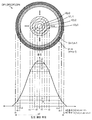
화상 투사 광학계(40)는, 화상을 나타내는 화상광을 생성하고, 스크린(피투사면)(SC) 상에서 결상(結像)시킴으로써 화상을 확대 투사한다. 이 화상 투사 광학계(40)는, 조명 광학계(420)와, 액정 라이트(light) 밸브(440)와, 투사 광학계(460)를 구비하고 있다.The image projection
조명 광학계(420)는, 광원 램프(422)와 램프 구동부(424)를 구비하고 있다. 광원 램프(422)로서는, 예를 들면, 초고압 수은 램프나 메탈 할라이드 램프를 포함하는 방전 발광형의 광원 램프, 레이저 광원, 발광 다이오드, 또는 유기 EL(Electro Luminescence) 소자 등의 각종 자기(自己) 발광 소자를 이용할 수 있다. 램프 구동부(424)는, 제어 회로(20)의 제어에 기초하여 광원 램프(422)를 구동한다.The illumination
액정 라이트 밸브(440)는, 조명 광학계(420)로부터 방사된 빛을 화상 데이터에 기초하여 변조하는 광변조 장치이다. 액정 라이트 밸브(440)는, 복수의 화소를 매트릭스 형상으로 배치한 투과형 액정 패널에 의해 구성된다. 후술하는 화상 처리 동작 회로(30)의 라이트 밸브 구동부(380)로부터의 구동 신호에 기초하여, 각 화소의 액정의 동작을 제어함으로써, 액정 라이트 밸브(440)S는, 조명 광학계(420)로부터 방사된 조명광을, 화상을 나타내는 화상광으로 변환한다. 또한, 본 실시예에서는, 액정 라이트 밸브(440)는, 적(R), 녹(G), 청(B)의 3개의 색 성분용의 3개의 액정 라이트 밸브(도시하지 않음)를 포함한다. 단, 1개의 액정 라이트 밸브를 이용하여 흑백 화상을 투사하도록 해도 좋다.The liquid crystal light valve 440 is an optical modulator that modulates light emitted from the illumination
투사 광학계(460)는, 액정 라이트 밸브(440)로부터 방사된 화상광을, 스크린(SC) 상에서 결상시킴으로써, 스크린(SC) 상에 화상을 확대 투사한다. 투사 광학계(460)는, 투사 렌즈(462)와, 렌즈 구동부(464)와, 상태 검출부(466)를 구비하고 있다. 투사 렌즈(462)는, 도시하지 않는, 포커스 조정용의 포커스 렌즈와, 줌 조정용의 줌 렌즈가 광축 방향으로 이동 가능하게 구성되어 있고, 액정 라이트 밸브(440)로부터 방사된 화상광을, 줌 렌즈의 줌 위치에 따라서 확대하고, 포커스 렌즈의 포커스 위치에 따라서 결상시킴으로써, 화상광이 나타내는 화상을 스크린(SC) 상에 확대 투사한다. 렌즈 구동부(464)는, 제어 회로(20)의 제어에 기초하여, 포커스 렌즈의 광축 방향의 위치(이하, 「포커스 위치」라고 함)를 변화시킨다. 또한, 렌즈 구동부(464)는, 줌 렌즈의 광축 방향의 위치(이하, 「줌 위치」)를 변화시킨다. 상태 검출부(466)는, 포커스 렌즈의 포커스 위치 및 줌 렌즈의 줌 위치를 검출한다. 또한, 투사 광학계(460)는 일반적인 구성을 가지기 때문에, 구체적인 구성의 도시 및 설명은 생략한다.The projection
화상 처리 동작 회로(30)는, 입력 처리부(320)와, 화상 표시 처리부(340)와, 화상 메모리(360)와, 라이트 밸브 구동부(380)를 구비하고 있다. 입력 처리부(320)는, 제어 회로(20)의 제어에 기초하여, 외부 기기로부터 공급되는 입력 화상 신호에 대하여, 필요에 따라서 A/D 변환을 행하고, 화상 표시 처리부(340)에서 처리 가능한 디지털 화상 신호로 변환한다. 화상 표시 처리부(340)는, 제어 회로(20)의 제어에 기초하여, 입력 처리부(320)로부터 출력된 디지털 화상 신호에 포함되는 화상 데이터를, 화상 메모리(360)에, 1프레임마다 기입하고, 읽어낼 때에, 해상도 변환 처리나 키스톤 보정 처리 등의 여러 가지의 화상 처리를 실시한다. 또한, 화상 표시 처리부(340)는, 제어부(220)로부터 출력된 검출 화상을 나타내는 검출 화상 데이터를, 화상 데이터에 서로 겹친다. 라이트 밸브 구동부(380)는, 화상 표시 처리부(340)로부터 입력된 디지털 화상 신호에 따라서, 액정 라이트 밸브(440)를 구동한다. 또한, 라이트 밸브 구동부(380)는, 화상 처리 동작 회로(30)가 아니라, 화상 투사 광학계(40)에 구비되도록 해도 좋다.The image
촬상부(50)는, 제어 회로(20)의 제어에 기초하여, 투사 화상을 촬상하고 촬상된 화상에 대응하는 화상 신호를 제어 회로(20)에 출력한다. 이 투사 화상은, 검출 화상으로서 입력 처리부(320)로부터 화상 표시 처리부(340)에 입력된 디지털 화상 신호가 나타내는 화상(PP)(해칭으로 나타냄)에 검출 화상(TP)(4개의 검출 화상 부분으로서의 4개의 도트 패턴(DP)으로 구성됨)이 서로 겹쳐진 화상이며, 스크린(SC)에 확대 투사된다. 이 촬상부(50)는, 예를 들면, 촬상 소자로서 CCD(Charge Coupled Device)를 구비한 CCD 카메라를 이용하여 구성된다. 또한, 검출 화상에 대해서는 후술한다.The
움직임 검출부(60)는, 프로젝터(PJ)에 있어서의, 투사축 둘레나, 종방향, 횡방향의 이동 및, 이동의 정지를 검출한다. 또한, 이 움직임 검출부는, 각(角)속도 센서, 가속도 센서, 자이로 센서 등의, 이동 및 이동의 정지를 검출하는 것이 가능한 각종 센서를 이용하여 구성할 수 있다.The
제어 회로(20)는, CPU나 ROM, RAM 등을 구비하는 컴퓨터이며, 제어 프로그램을 실행함으로써, 제어부(220)와 정보 기억부(260)를 구성한다. 제어부(220)는, 실행된 제어 프로그램에 따라, 화상 처리 동작 회로(30), 화상 투사 광학계(40), 촬상부(50) 및, 움직임 검출부(60)를 각각 제어하는 각종 제어 기능부로서 동작한다. 정보 기억부(260)는, 각종 제어 동작을 위한 정보를 기억하는 각종 기억부로서 동작한다. 도 1에는, 제어부(220)의 제어 기능부의 예로서, 후술하는 검출 화상 조정을 실행하는 검출 화상 조정부(230) 및, 포커스 조정이나 키스톤 보정(키스톤 왜곡 보정) 등의 투사 화상의 화질을 조정하는 투사 화상 조정부(240)가 도시되어 있다. 이 검출 화상 조정부(230)는, 이용자가 입력 조작부(10)로부터 검출 화상 조정의 개시를 지시함으로써, 대응하는 프로그램이 실행됨으로써 동작한다. 또한, 도 1에는, 정보 기억부(260)의 기억부의 예로서, 제어부(220)에 의한 여러 가지의 제어에 사용되는 설정 정보를 기억하는 설정 정보 기억부(262)와, 후술하는 검출 화상 정보를 기억하는 검출 화상 정보 기억부(264)와, 촬상부(50)에서 촬상된 촬상 화상의 화상 데이터를 기억하는 촬상 화상 정보 기억부(266)가 도시되어 있다.The control circuit 20 is a computer having a CPU, a ROM, and a RAM, and constitutes a
검출 화상 조정부(230)는, 검출 화상 생성부(232)와, 촬상 제어부(234)와, 화상 해석부(236)와, 무게 중심 좌표 검출부(238)를 구비하고 있다. 검출 화상 생성부(232)는, 포커스 조정이나 키스톤 보정을 위해 이용되는 검출 화상의 화상 데이터를 생성한다. 촬상 제어부(234)는, 촬상부(50)를 제어하여 스크린(SC) 상에 투사된 검출 화상을 포함하는 투사 화상을 촬상하고, 촬상한 투사 화상(이하, 「촬상 화상」이라고도 함)을 촬상 화상 정보 기억부(266)에 기억한다. 화상 해석부(236)는 촬상 화상을 해석한다. 또한, 화상 해석부(236)는, 검출 화상 생성부(232) 중에 형성해도 좋다. 무게 중심 좌표 검출부(238)는, 후술하는 바와 같이, 투사 화상 조정부(240)에 의한 포커스 조정이나 키스톤 보정 등의 화질 조정을 위해 이용되는 무게 중심 좌표를 검출한다. 이 검출 화상 조정부(230)에 대해서는, 추가로 후술한다.The detection
또한, 본 실시예에 있어서, 검출 화상 생성부(232) 및 화상 해석부(236)는 본 발명의 검출 화상 생성부에 상당한다. 또한, 제어 회로(20) 및 화상 처리 동작 회로(30)는, 본 발명의 화상 처리 장치에 상당한다.In the present embodiment, the detected
B. 프로젝터의 동작:B. Operation of the projector:
[검출 화상 조정의 동작 설명][Explanation of Operation of Detected Image Adjustment]
도 2는, 본 실시예에 있어서의 검출 화상 조정 처리를 나타내는 플로우 차트이다. 제어부(220)의 검출 화상 조정부(230)(도 1)가 검출 화상 조정 처리를 개시하면, 검출 화상 조정부(230)의 검출 화상 생성부(232)는, 검출 화상을 생성한다(스텝 S10). 생성된 검출 화상의 화상 데이터(이하, 「검출 화상 데이터」라고도 함)는 화상 처리 동작 회로(30)의 화상 표시 처리부(340)(도 1)에 출력된다.2 is a flowchart showing the detected image adjustment processing in the present embodiment. When the detected image adjusting unit 230 (Fig. 1) of the
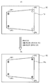
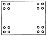
도 3a 및 도 3b는, 생성되는 검출 화상에 대해서 나타내는 설명도이다. 이 검출 화상(TP)은, 도 3a에 나타내는 바와 같이, 액정 라이트 밸브(440)의 매트릭스 형상으로 배치된 복수의 화소(액정 화소)에 의해 구성되는 화상 형성 영역(440f)의 네 모퉁이의 소정의 위치에 배치되어야 할 4개의 검출 화상 부분으로서의 도트 패턴(DP1∼DP4)으로 구성된다. 화상 형성 영역(440f)의 좌상, 우상, 좌하, 우하에 위치되는 4개의 정점의 좌표(수평, 수직 방향)는, (0, 0), (xx, 0), (0, yy), (xx, yy)로 나타나고 있는 것으로 한다. 이 경우에, 4개의 도트 패턴(DP1∼DP4)은, 화상 형성 영역(440f)의 좌표계에 있어서, 각각의 중심(무게 중심)이 미리 정해진 좌표(x1, y1), (x2, y2), (x3, y3), (x4, y4)에 배치되는 것으로 한다. Figs. 3A and 3B are explanatory views showing the detected image to be generated. Fig. As shown in Fig. 3A, this detected image TP is a predetermined image of four corners of the
각 도트 패턴(DP1∼DP4)은, 도 3b에 나타내는 바와 같이, 도트 패턴의 사이즈(직경)가 sd(단위는 예를 들면 [pixel])의 원형 패턴이며, 중심으로부터 외주(外周)를 향하여 변화하는 계조 단수가 stp(stp는 3 이상의 정수)인 복수단의 영역으로 구분되고, 중심의 영역으로부터 외주의 영역을 향하여 순서대로 명도가 낮아지는 다중 단(level)의 명도 분포를 갖는다. 도 3b의 예에서는, 명도 분포는 가우스 분포를 모의한 형상이다. 또한, 각 영역의 번호를 n으로 하여 n은 중심으로부터 외측을 향하여 0에서 stp-1까지의 번호가 순서대로 할당되는 것으로 한다. 1단째의 영역(중심 영역)의 번호는 n=0이고, 그 명도값(예를 들면 8비트의 계조값)은 V0이며 그 반경은 r0(단위는 예를 들면 [pixel])으로 나타난다. 마찬가지로, 2단째의 영역의 번호는 n=1이고, 그 명도값은 V1이며 그 반경은 r1[pixel]로 나타난다. 또한, 3단째의 영역의 번호는 n=2이고, 그 명도값은 V2이며 반경은 r2[pixel]로 나타난다. 즉, n단째의 영역의 번호는 n=0∼stp-1이고, 그 명도값은 Vn이며 그 반경은 rn[pixel]로 나타난다. 또한, 도트 패턴의 사이즈(sd)는, 화소수[pixel]가 홀수인 경우에는, 중심을 0으로 규정하는 -rn∼+rn의 범위에서 sd=(2·rn)으로 나타난다. 이에 비하여, 화소수가 홀수인 경우에는, 도트 패턴의 사이즈(sd)는, -rn∼+(rn-1) 혹은 -(rn-1)∼+rn의 범위에서 sd=(2·rn)-1로 나타난다. 검출 화상(TP)를 구성하는 각 도트 패턴(DP1∼DP4)의 생성 방법에 대해서는 추가로 후술한다.As shown in Fig. 3B, each of the dot patterns DP1 to DP4 is a circular pattern having a size (diameter) of the dot pattern of sd (the unit is, for example, [pixel]) and varies from the center toward the outer periphery (Stp is an integer of 3 or more), and has a multilevel brightness distribution in which the brightness gradually decreases from the center area toward the outer periphery area. In the example of FIG. 3B, the brightness distribution is a shape simulating the Gaussian distribution. In addition, assume that the number of each area is n, and the numbers from 0 to stp-1 are sequentially allocated from the center toward the outside. The number of the first-stage region (central region) is n = 0, and the luminosity value (for example, 8-bit tone value) is V0 and its radius is represented by r0 (unit is, for example, [pixel]). Similarly, the number of the second-stage region is n = 1, the brightness value thereof is V1, and its radius is represented by r1 [pixel]. In addition, the number of the third-stage region is n = 2, the brightness value thereof is V2, and the radius is represented by r2 [pixel]. That is, the number of the n-th region is n = 0 to stp-1, the brightness value thereof is Vn, and the radius thereof is represented by rn [pixel]. Further, the size (sd) of the dot pattern is represented by sd = (2 · rn) in the range of -rn to + rn where the center is defined as 0 when the number of pixels is an odd number. On the other hand, when the number of pixels is an odd number, the size (sd) of the dot pattern is sd = (2 · rn) -1 in the range of -rn to + (rn-1) appear. A method of generating the dot patterns DP1 to DP4 constituting the detected image TP will be further described later.
여기에서, 도 3b에 나타내는 바와 같은 도트 패턴을 사용하는 이유는, 개개의 도트 패턴의 무게 중심 좌표를 구하는 처리에 있어서, 그 무게 중심 좌표를 정밀하게 결정하는 데에 도트 패턴이 적합하기 때문이다. 무게 중심 좌표를 구하는 처리에 대해서는 후술한다. Here, the reason why the dot pattern shown in Fig. 3B is used is that the dot pattern is suitable for precisely determining the coordinates of the center of gravity in the process of obtaining the center-of-gravity coordinates of the individual dot patterns. Processing for obtaining the center-of-gravity coordinate will be described later.
상기 스텝 S10에 의한 검출 화상의 생성 후, 스텝 S20∼스텝 S60b가 실행되고, 스텝 S10으로 되돌아와 스텝 S10 이후의 처리가 다시 실행된다. 따라서, 검출 화상 조정이 실행된다. 이하에서는, 스텝 S20 이후의 처리를 구체적으로 설명하기 전에, 우선, 스텝 S10에서 생성된 검출 화상을 이용한 검출 화상 조정의 개요를 설명한다.After the generation of the detection image by the step S10, steps S20 to S60b are executed, and the process returns to the step S10 and the processes after the step S10 are executed again. Therefore, the detected image adjustment is performed. Hereinafter, the outline of the detected image adjustment using the detected image generated in step S10 will be described first, before the processing after step S20 is specifically described.
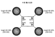
도 4는, 도 2의 스텝 S10에서 생성된 검출 화상을 이용하여 실행되는 검출 화상 조정 처리의 개요에 대해서 나타내는 설명도이다. 스텝 S10에서 생성된 검출 화상(TP)은, 후술하는 스텝 S20에 있어서, 예를 들면, 도 4(A)에 나타내는 바와 같이, 스크린(SC) 상에 투사 표시된다. 이 경우, 투사 표시된 검출 화상(TP)은, 우상 및 우하에 위치되는 도트 패턴(DP2, DP4)의 명도가 좌상 및 좌하에 위치되는 도트 패턴(DP1, DP3)의 명도에 비하여 낮은 상태에 있는 것으로 한다. 이 경우, 후술하는 스텝 S30에 의한 투사 화상의 촬상 및, 스텝 S60b, S10에 의한 검출 화상의 수정이 실행된다. 이 결과, 도 4(B)에 나타내는 바와 같이, 스텝 S20에 있어서의 수정 후의 검출 화상의 재투사에 의해 투사 표시된 검출 화상(TPa)에서는, 각 검출 화상 부분(DP1∼DP4)의 명도값이 서로 거의 동일해지도록 조정이 실행된다.Fig. 4 is an explanatory diagram showing an overview of detected image adjustment processing executed using the detection image generated in step S10 of Fig. 2; Fig. The detected image TP generated in step S10 is projected on the screen SC, for example, as shown in Fig. 4 (A) in step S20 described later. In this case, the projected detected image TP is in a state in which the brightness of the dot patterns DP2 and DP4 positioned at the upper right and lower right is lower than the brightness of the dot patterns DP1 and DP3 positioned at the upper left and lower left do. In this case, the imaging of the projection image by the step S30 described later and the correction of the detected image by the steps S60b and S10 are executed. As a result, as shown in Fig. 4B, in the detected image TPa projected by the re-projection of the detected image after the correction in step S20, the brightness values of the respective detected image portions DP1 through DP4 are different from each other The adjustment is performed so as to become substantially the same.
다음으로, 도 2의 스텝 S20 이후에 실행되는 각 처리에 대해서 설명한다. 스텝 S20에서는, 검출 화상 조정부(230)의 검출 화상 생성부(232)로부터 화상 표시 처리부(340)에 출력된 검출 화상 데이터가 나타내는 검출 화상(TP)이, 화상 처리 동작 회로(30)의 입력 처리부(320)로부터 화상 표시 처리부(340)에 출력된 화상 데이터가 나타내는 화상에 중첩되고, 다음으로 라이트 밸브 구동부(380) 및, 화상 투사 광학계(40)(도 1)를 통해 스크린(SC) 상에 투사 표시된다. 다음으로, 스텝 S30에서는, 검출 화상 조정부(230)의 촬상 제어부(234)(도 1)에 의해 촬상부(50)가 제어되어, 스크린(SC) 상에 투사 표시되어 있는 검출 화상을 포함하는 투사 화상이 촬상되고, 촬상 화상의 화상 데이터(「촬상 화상 데이터」라고도 함)가 취득되어, 촬상 화상 정보 기억부(266)에 기억된다.Next, each process executed after step S20 of Fig. 2 will be described. The detected image TP indicated by the detected image data output from the detected
스텝 S40에서는, 검출 화상 조정부(230)의 화상 해석부(236)(도 1)는, 검출 화상(TP)을 구성하는 도트 패턴(검출 화상 부분)(DP1∼DP4)에 대응하는, 촬상 화상 데이터를 나타내는 촬상 화상 중의 각 검출 화상 부분(이하, 「촬상 검출 화상 부분」이라고도 함)의 명도를 구한다. 구체적으로는, 예를 들면, 촬상 화상에 있어서, 도트 패턴(DP1∼DP4)에 각각 대응하는 검출 화상 부분이 존재해야 할 대략의 위치가 특정될 수 있기 때문에, 각 검출 화상 부분을 포함하는 대략의 범위 내에 있어서의 각 화소의 명도의 최대값이 검출되고, 검출된 명도의 최대값이 각 검출 화상 부분의 명도로서 판정된다.1) corresponding to the dot patterns (detected image portions) DP1 to DP4 constituting the detected image TP, the
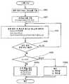
스텝 S50에서는, 화상 해석부(236)는, 촬상 화상 중의 검출 화상 부분의 명도(명도의 최대값)가 모두 허용 범위 내에 있는지 아닌지를 판단함으로써, 검출 화상의 수정의 필요성을 판단한다. 구체적으로, 이 판단은 촬상 화상 중의 검출 화상 부분의 명도의 최대값이, 모두, 8비트 계조로 230∼250(최대 계조값 255에 대한 비율로 나타내면 90∼98%)의 범위 내에 있는지 아닌지로 판단함으로써 성취될 수 있다. 또한, 이 범위는, 예시에 불과하고 반드시 이것에 한정되는 것이 아니고, 요구되는 조정 정밀도에 따른 범위로 설정하면 좋다.In step S50, the
스텝 S60a에서는, 구해진 촬상 화상 중의 각 검출 화상 부분의 명도값(명도의 최대값)이 모두 허용 범위에 있어, 검출 화상의 수정이 불필요하다라고 판단된 경우에(스텝 S50: YES), 검출 화상 조정부(230)의 무게 중심 좌표 검출부(238)(도 1)는, 검출 화상(TP)을 구성하는 검출 화상 부분인 도트 패턴(DP1∼DP4)에 대응하는, 촬상 화상 중의 각 검출 화상 부분의 무게 중심 좌표를 구한다. 다음으로, 여기에서 구해진 무게 중심 좌표에 기초하여, 추가로, 포커스 조정이나 키스톤 보정 등의 여러 가지의 조정이 실행된다. 이 무게 중심 좌표를 구하는 방법에 대해서는 후술한다.If it is determined in step S60a that the brightness values (maximum values of brightness) of the detected image portions in the obtained captured image are all in the permissible range and correction of the detected image is unnecessary (step S50: YES) The center of gravity coordinate detection unit 238 (Fig. 1) of the
스텝 S60b에서는, 구해진 촬상 화상 중의 각 검출 화상 부분의 명도값(명도의 최대값) 중 어느 하나가 허용 범위 밖에 있어, 검출 화상의 수정이 필요하다라고 판단된 경우에(스텝 S50: NO), 검출 화상 생성부(232)는, 검출 화상(TP)을 수정하기 위한 수정 정보를 구한다. 다음으로, 스텝 S10으로 되돌아와, 구해진 수정 정보에 기초하여 검출 화상이 수정되고, 수정된 검출 화상의 화상 데이터가 화상 표시 처리부(340)에 출력되고, 스텝 S50에 있어서 검출 화상의 수정이 불필요하다라고 판단될 때까지, 스텝 S10∼스텝 S60b의 처리가 반복된다. 수정 정보를 구하는 처리(스텝 S60b)에 대해서는 후술한다.If it is determined in step S60b that any one of the brightness values (maximum brightness values) of the detected image portions in the obtained captured image is outside the allowable range and correction of the detected image is necessary (step S50: NO) The
이상 설명한 바와 같이, 검출 화상 조정 처리에서는, 촬상 화상 중의 각 검출 화상 부분의 명도값이 서로 거의 동일해지도록 검출 화상의 조정이 실행된다.As described above, in the detected image adjustment processing, the adjustment of the detected image is performed such that the brightness values of the detected image portions in the captured image become substantially equal to each other.
[검출 화상의 생성 방법][Method of generating detected image]
도 5는, 도 2의 스텝 S10에 있어서 검출 화상을 구성하는 검출 화상 부분으로서의 도트 패턴을 생성하는 순서에 대해서 나타내는 플로우 차트이다. 우선, 도트 패턴 사이즈(sd)의 결정(스텝 S110), 명도의 계조 단수(stp)의 결정(스텝 S120) 및, 표준 편차(σ)의 결정(스텝 S130)이 실행된다. 또한, 검출 화상 조정의 개시 시점에 있어서, 이들 파라미터(sd, stp, σ)는 미리 정해져 있는 값으로 설정된다. 이하의 설명에서는, 초기 설정값의 예로서, sd=34[pixel], stp=10[단], σ=10[pixel]이 설정되어 있는 것으로 하여 설명한다.5 is a flowchart showing a procedure for generating a dot pattern as a detected image portion constituting a detected image in step S10 in Fig. First, the determination of the dot pattern size sd (step S110), the determination of the gradation level stp of brightness (step S120) and the determination of the standard deviation sigma (step S130) are performed. Further, at the start of the detected image adjustment, these parameters sd, stp, and? Are set to predetermined values. In the following description, it is assumed that sd = 34 [pixel], stp = 10 [step], and [sigma] = 10 [pixel] are set as examples of the initial setting values.
다음으로, 하기식 (1)로 나타내는 정규 분포 함수 A(s)로부터, s=0 및 s=sd/2에 있어서의 확률 밀도 A(0) 및 A(sd/2)의 값을 각각 산출하고(스텝 S140), 하기식 (2)로 나타내는 배분식으로부터, 계조 단수(stp)의 1단당의 배분값(Pa)을 산출한다(스텝 S150).Next, the values of the probability density A (0) and A (sd / 2) at s = 0 and s = sd / 2 are calculated from the normal distribution function A (s) (Step S140) and the distribution value Pa per stage of the gradation stage number stp is calculated from the classification formula shown by the following formula (2) (step S150).
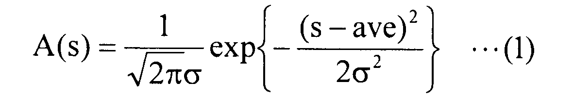
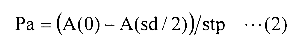
상기 초기 설정 sd=34, stp=10, σ=10의 경우에는, 평균값(ave)을 0으로 하여 식 (1)로부터 A(0)=0.03989 및 A(sd/2)=A(17)=0.00940이 구해지고, 식 (2)로부터 Pa=0.00305가 구해진다. 이들 각 수치는 편의상 소수점 이하 5 자리수로 사사오입하여 나타나고 있다. 또한, 도 3b를 참조하여 설명한 바와 같이, 도트 패턴의 사이즈(sd)가 짝수 화소수인 경우에는, sd가 -rn∼+(rn-1)의 범위에서 나타나고, 평균값(ave)은 0이 아니라 -0.5가 되지만, 상기한 바와 같이 ave=0으로 한 것은, 홀수 화소수의 경우와 동일하게 -rn∼+rn의 범위로 가정해도 계산상 거의 문제가 없다고 생각되기 때문이다. 예를 들면, sd=34인 경우에, 실제의 -17∼+16의 범위로 생각한 경우와, -17∼+17의 범위로 생각한 경우에서, 그 산출값의 차이는, 최대값 A(0)측에서 약 0.00005, 최소값 A(17)측에서 약 0.00083이며, 거의 동일한 값이라고 생각해도 지장 없다.(1) to A (0) = 0.03989 and A (sd / 2) = A (17) = 0 when the initial setting sd = 34, stp = 10 and? = 10, 0.00940 is obtained, and Pa = 0.00305 is obtained from the equation (2). Each of these figures is rounded to five decimal places for convenience. 3B, when the size sd of the dot pattern is an even number of pixels, sd appears in the range of -rn to + (rn-1), and the average value ave is not 0 -0.5. The reason why ave = 0, as described above, is considered to be almost no problem in calculation even when it is assumed to be in the range of -rn to + rn as in the case of the odd number of pixels. For example, in the case of sd = 34, the difference between the calculated values in the range of -17 to +16 and -17 to +17 in the actual range of A (0) About 0.00005 at the minimum value A (17) side, and about 0.00083 at the minimum value A (17) side.
다음에, 각 단의 반경(rn)(n: 0∼stp-1=9)를 산출한다(스텝 S160). 구체적으로는, 하기식 (3)이 성립하는 반경(rn)을 산출한다.Next, the radius rn (n: 0 to stp-1 = 9) of each stage is calculated (step S160). Specifically, the radius rn in which the following equation (3) holds is calculated.
![]()
![]()
상기 초기 설정 sd=34, stp=10, σ=10의 경우에는, 각 단의 반경(r0∼r9)은, r0=4[pixel], r1=6[pixel], r2=7[pixel], r3=9[pixel], r4=10[pixel], r5=11[pixel], r6=12[pixel], r7=14[pixel], r8=15[pixel], r9=17[pixel]과 같이 구해진다.R0 = 4 [pixel], r1 = 6 [pixel], r2 = 7 [pixel], and r2 = 7 [pixel] in the case of the initial setting sd = 34, stp = 10, r7 = 14 [pixel], r8 = 15 [pixel], r9 = 17 [pixel] as r3 = 9 [pixel], r4 = 10 [pixel], r5 = 11 [pixel] Is obtained.
다음으로, 각 단의 영역이 특정된다(스텝 S170). 구체적으로는, 도트 패턴의 중심 좌표를 원점으로 규정하여, 하기식 (4)에 기초하여 각 단의 영역이 특정된다. 구체적으로는, 하기식 (4)로 나타나는 반경(rn)의 원이 영역 간의 경계가 되고, 그 내측의 영역이 각각의 영역으로서 특정된다. 따라서, (rn-1)2=x2+y2로 나타나는 원과 rn2=x2+y2로 나타나는 원의 사이의 영역이 n단째인 영역에 대응된다.Next, the area of each stage is specified (step S170). Specifically, the center of the dot pattern is defined as the origin, and the area of each end is specified based on the following equation (4). Specifically, the circle of the radius rn represented by the following formula (4) becomes the boundary between the regions, and the inside region is specified as the respective regions. Therefore, the region between the circles represented by (rn-1) 2 = x 2 + y 2 and the circles represented by rn 2 = x 2 + y 2 corresponds to the region in the n-th row.

마지막으로, 각 단의 명도의 계조값(명도값)(Vn)을 설정한다(스텝 S180). 구체적으로는, 예를 들면, 하기식 (5)에 기초하여 각 단의 명도값(Vn)을 설정할 수 있다.Finally, the gradation value (brightness value) Vn of the brightness of each stage is set (step S180). Specifically, for example, the brightness value Vn of each stage can be set based on the following equation (5).

상기 초기 설정 sd=34, stp=10, σ=10의 경우에 있어서, 1단째(반경 r0)∼10단째(반경 r9)의 각 영역의 명도값(V0∼V9)은, 예를 들면, V0: 흰색 98%(8비트의 최대 계조값(255)에 대한 비율)로 하면, V1: 흰색 88%, V2: 흰색 78%, V3: 흰색 68%, V4: 흰색 58%, V5: 흰색 48%, V6: 흰색 38%, V7: 흰색 28%, V8: 흰색 18%, V9: 흰색 8%와 같이 구해진다.The brightness values (V0 to V9) of the respective regions of the first stage (radius r0) to the tenth stage (radius r9) in the initial setting sd = 34, stp = 10 and sigma = : White 88%, V2: White 78%, V3: White 68%, V4: White 58%, V5: White 48%,
[수정 정보를 구하는 방법][How to obtain correction information]
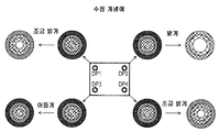
도 6a, 도 6b, 도 7a ~ 도 7c는, 수정 정보를 구하는 방법에 대해서 나타내는 설명도이다. 도 6a는 검출 화상을 나타내고, 도 6b는 촬상 결과를 나타내고, 도 7a는 수정 개념예를 나타내고, 도 7b는 수정 내용의 구체적인 일 예를 나타내고 있다. 또한, 도 6a에 나타내는 바와 같이, 각 도트 패턴(검출 화상 부분) (DP1∼DP4)의 명도의 최대값(Vdp1∼Vdp4)은 명도의 설정 가능한 최대값에 대한 비율로 98%(8비트로 250)로 설정되어 있는 것으로 하여 설명한다. 또한, 이하에서는, 예를 들면, 도트 패턴(DP1)의 명도의 최대값(Vdp1)을 단순히 「명도값(Vdp1)」라고도 부른다. 또한, 도 6a에 나타낸 검출 화상의 각 도트 패턴(DP1∼DP4)은, 도시를 용이하게 하기 위해, 명도 분포의 단수를 상기에서 예시한 stp=10보다도 적게 한 stp=5로 나타내고 있다. 또한, 해칭의 밀도는 각 단 사이의 명도값의 대소 관계를 나타내고, 구체적으로는, 해칭의 밀도가 높을수록 명도값이 작고, 해칭의 밀도가 낮을수록 명도값이 크게 나타난다.Figs. 6A, 6B, 7A to 7C are explanatory diagrams showing a method for obtaining correction information. FIG. 6A shows the detected image, FIG. 6B shows the imaging result, FIG. 7A shows the modification concept example, and FIG. 7B shows a specific example of the modification contents. 6A, the maximum value (Vdp1 to Vdp4) of brightness of each dot pattern (detected image portion) DP1 to DP4 is 98% (250 bits in 8 bits) as a ratio to the maximum value of brightness settable, As shown in Fig. In the following description, for example, the maximum value Vdp1 of the brightness of the dot pattern DP1 is also simply referred to as " brightness value Vdp1 ". Each dot pattern DP1 to DP4 of the detected image shown in Fig. 6A is represented by stp = 5 in which the number of stages of the brightness distribution is made smaller than stp = 10 shown in the above for ease of illustration. In addition, the density of hatching represents the magnitude of the brightness value between the respective stages. Specifically, the higher the density of hatching, the smaller the brightness value, and the lower the hatching density, the greater the brightness value.
도 6a에 나타낸 검출 화상이 투사되고, 도 6b에 나타내는 바와 같이, 각 도트 패턴(DP1∼DP4)에 대응하는 검출 화상 부분(촬상 검출 화상 부분)(SDP1∼SDP4)이 얻어진 것으로 한다. 결과적으로, 좌상에 위치되는 촬상 검출 화상 부분(SDP1)의 명도값(명도의 최대값)(Vsdp1)은 75%(8비트로 191), 우상에 위치되는 촬상 검출 화상 부분(SDP2)의 명도값(Vsdp2)은 60%(8비트로 153), 좌하에 위치되는 촬상 검출 화상 부분(SDP3)의 명도값(Vsdp3)은 100%(8비트로 255) 및, 우하에 위치되는 촬상 검출 화상 부분(SDP4)의 명도값(Vsdp4)은 80%(8비트로 204)가 된다. 또한, 좌하에 위치되는 촬상 검출 화상 부분(SDP3)의 좌측에 나타낸 바와 같이, 포화 추출(밝게 추출)된 경우에 있어서도, 명도값은 100%(8비트로 255)가 된다.It is assumed that the detected images shown in Fig. 6A are projected and detected image portions (image sensing detected image portions) (SDP1 to SDP4) corresponding to the respective dot patterns DP1 to DP4 are obtained as shown in Fig. 6B. As a result, the brightness value (maximum brightness value) Vsdp1 of the image sensing detected image portion SDP1 located at the upper left is 75% (191 by 8 bits), the brightness value of the image sensing detected image portion SDP2 The brightness value Vsdp3 of the image sensing detected image portion SDP3 positioned at the lower left is 100% (8 bits by 255), and the lower limit of the brightness value Vsdp2 of the image sensing detected image portion SDP4 The brightness value Vsdp4 is 80% (204 bits in 8 bits). Also, as shown on the left side of the image sensing detected image portion SDP3 located at the lower left, the brightness value becomes 100% (255 in 8 bits) even when saturation extraction (bright extraction) is performed.
여기에서, 검출 화상의 각 도트 패턴(DP1∼DP4)에 대응하는 촬상 검출 화상 부분(SDP1∼SDP4)의 무게 중심 좌표를 정밀하게 취득하기 위해서는, 각 촬상 검출 화상 부분(SDP1∼SDP4)의 명도값(명도의 최대값)이 90%(8비트로 230) 이상인 것이 바람직하다. 또한, 명도값이 100%(8비트로 255)인 경우에는, 상기한 바와 같이 포화 추출된 경우도 있을 수 있다. 따라서, 상한의 명도값은 98%(8비트로 250) 정도로 하는 것이 바람직하다. 따라서, 4개의 각 촬상 검출 화상 부분(SDP1∼SDP4)의 명도값(Vsdp1∼Vsdp4)이 미리 정한 허용 범위(90∼98%(8비트로 230∼250))에 들어가, 대략 동일해지도록, 검출 화상의 각 도트 패턴(DP1∼DP4)의 명도값(Vdp1∼Vdp4)을 수정하면 되게 된다. 또한, 허용 범위의 상한을 반드시 98%(8비트로 250)로 해야 하는 것은 아니고, 포화 추출되지 않는 한 상한은 100%(8비트로 255)로 설정될 수 있다.Here, in order to precisely acquire the center of gravity coordinates of the image sensing detected image portions SDP1 to SDP4 corresponding to the dot patterns DP1 to DP4 of the detected image, the brightness values of the image sensing detected image portions SDP1 to SDP4 (Maximum value of brightness) is 90% (230 bits in 8 bits) or more. In addition, when the brightness value is 100% (255 bits in 8 bits), the saturation extraction may be performed as described above. Therefore, it is preferable that the brightness value of the upper limit is 98% (250 bits in 8 bits). Therefore, the brightness values (Vsdp1 to Vsdp4) of the four imaging sensed image portions SDP1 to SDD4 are set to fall within a predetermined allowable range (90 to 98% (8 bits to 230 to 250)), The brightness values Vdp1 to Vdp4 of the dot patterns DP1 to DP4 of the dot patterns DP1 to DP4 can be corrected. In addition, the upper limit of the allowable range is not necessarily 98% (250 bits in 8 bits), and the upper limit can be set to 100% (255 bits in 8 bits) unless saturated extraction is performed.
따라서, 예를 들면, 도 6b에 나타내는 촬상 결과의 경우에, 4점의 촬상 검출 화상 부분(SDP1∼SDP4)의 명도값(Vsdp1∼Vsdp4)이 허용 범위 내에 들어가 대략 동일해지도록 하려면, 단순한 개념으로는, 이하와 같이 하면 좋다. 즉, 도 7a에 나타내는 바와 같이, 좌상과 우상과 우하에 위치되는 도트 패턴(DP1, DP2, DP4)의 명도값(Vdp1, Vdp2, Vdp4)을, 도트 패턴이 얼마나 어둡게 추출되는지의 정도에 따라서 높게 한 명도값으로 수정하고, 좌하에 위치된 도트 패턴(DP3)의 명도값(Vdp3)을, 도트 패턴이 얼마나 밝게 추출되는지의 정도에 따라서 낮게 한 명도값으로 수정하여, 도트 패턴에 각각 대응하는 촬상 검출 화상 부분(SDP1∼SDP4)의 명도값(Vsdp1∼Vsdp4)이 서로 거의 동일해지도록 하면 좋다.Therefore, for example, in the case of the imaging result shown in Fig. 6B, in order to make the brightness values (Vsdp1 to Vsdp4) of the four points of the image sensing detection image portions SDP1 to SDD4 fall within the allowable range and become substantially the same, May be as follows. 7A, the brightness values Vdp1, Vdp2, and Vdp4 of the dot patterns DP1, DP2, and DP4 positioned at the upper left, upper right, and lower right are set to be higher according to how dark the dot pattern is extracted The luminosity value Vdp3 of the dot pattern DP3 located at the lower left is corrected to a brightness value lowered according to how bright the dot pattern is extracted so that the luminosity The brightness values Vsdp1 to Vsdp4 of the detected image portions SDP1 to SDD4 may be made substantially equal to each other.
여기에서, 우상에 위치되는 도트 패턴(DP2)의 경우와 같이, 대응하는 촬상 검출 화상 부분(SDP2)의 명도값(Vsdp2)이 60%로 낮은 경우에는, 상기 수정 개념에 따르면, 원래의 설정한 명도값(Vdp2)(98%)보다도 약 1.6배 높게 한 명도값으로 수정하게 된다. 그러나, 거의 100%에 가까운 명도값이 설정되어 있기 때문에, 단순하게 명도값의 설정을 높게 하는 것만으로는, 대응하는 수정을 행할 수 없게 된다. 또한, 좌하에 위치되는 도트 패턴(DP3)의 경우에서와 마찬가지로, 대응하는 촬상 검출 화상 부분(SDP3)의 명도값(Vsdp3)이 100%인 경우, 포화되어 있는 상태도 생각할 수 있어, 단순하게 도트 패턴이 얼마나 추출되는지의 정도에 따라서 낮게 할 수 없을 가능성도 있다.Here, when the brightness value Vsdp2 of the corresponding image sensing detected image portion SDP2 is as low as 60%, as in the case of the dot pattern DP2 positioned on the upper right, according to the above modification concept, It is corrected to a brightness value that is about 1.6 times higher than the brightness value (Vdp2) (98%). However, since a brightness value close to nearly 100% is set, it is not possible to perform corresponding correction simply by increasing the setting of the brightness value. Also, as in the case of the dot pattern DP3 located at the lower left, when the brightness value Vsdp3 of the corresponding image sensing detected image portion SDP3 is 100%, the saturated state can be considered, Depending on how much the pattern is extracted, it may not be possible to lower it.
그런데, 촬상부(50)에 이용되는 카메라에는 일반적으로 노출 조정 기능이 구비되어 있기 때문에, 화상의 밝기에 따라서 자동적으로 노출이 조정된다. 따라서, 노출 조정 없이 촬상 화상의 명도값이 90%(8비트로 230)보다도 낮게 되어 있어도, 노출의 조정에 의해, 촬상 화상의 명도값이 전체적으로 높아지도록 조정되는 것을 알 수 있다. 따라서, 촬상 검출 화상 부분의 각각의 명도값이 90%보다도 낮아도, 각각의 명도값이 거의 동일해지도록 수정된다면, 노출 조정의 효과에 의해 촬상 검출 화상의 각 검출 화상 부분(촬상 검출 화상 부분)의 명도값이 허용 범위 내에 들어가도록 수정하는 것이 가능하다고 생각된다.Since the camera used in the
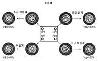
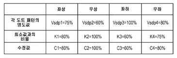
따라서, 본 예에서는, 이하와 같이 수정한다. 즉, 도 7b에 나타내는 바와 같이, 가장 어둡게 추출된 촬상 검출 화상 부분을 기준으로 하여, 이에 대응하는 도트 패턴의 명도값(명도의 최대값)이 설정되고, 그보다도 밝게 추출된 촬상 검출 화상 부분에 대응하는 도트 패턴의 명도값(명도의 최대값)은, 가장 어둡게 추출된 촬상 검출 화상 부분의 명도값(명도의 최대값)과의 관계에 따라 어둡게 설정되고, 따라서 각 촬상 검출 화상 부분의 명도값(명도의 최대값)이 서로 거의 동일해지도록 하는 것을 생각할 수 있다. 구체적으로는, 예를 들면, 도 6b의 우상에 위치되는 가장 어둡게 추출된 촬상 검출 화상 부분(SDP2)에 대응하는 도트 패턴(DP2)을 기준으로 하고, 그 명도값(Vdp2)을 가장 밝아지도록 100%로 수정한다. 좌하에 위치되는 가장 밝게 추출된 촬상 검출 화상 부분(SDP3)에 대응하는 도트 패턴(DP3)의 명도값(Vdp3)을, 대응하는 촬상 검출 화상 부분(SDP3)의 명도값(Vsdp3)과, 기준으로 한 촬상 검출 화상 부분(SDP2)의 명도값(Vsdp2)과의 차이에 따라서, 기준보다 어두워지도록, 60%로 수정한다. 좌상 및 우하에 각각 위치되고, 중간의 어둡기로 추출된 촬상 검출 화상 부분(SDP1, SDP4)에 대응하는 도트 패턴(DP1, DP4)의 명도값(Vdp1, Vdp4)을, 촬상 검출 화상 부분(SDP1, SDP4)의 명도값(Vsdp1, Vsdp4)과, 기준으로 한 촬상 검출 화상 부분(SDP2)의 명도값(Vsdp2)과의 차이에 따라서, 기준보다 조금 어두워지도록, 각각, 80%로 수정한다. 수정값을 구하는 구체적인 방법예에 대해서는, 이하에서 설명한다.Therefore, in this example, correction is made as follows. That is, as shown in FIG. 7B, the brightness value (maximum value of brightness) of the dot pattern corresponding thereto is set with reference to the darkest extracted image sensing detected image portion, and the brightness of the image sensing detected image portion The brightness value (maximum value of brightness) of the corresponding dot pattern is set to be dark according to the relationship with the brightness value (maximum value of brightness) of the most darkly extracted image sensing detected image portion, (The maximum value of brightness) are made almost equal to each other. Specifically, for example, the dot pattern DP2 corresponding to the darkest extracted image sensing detected image portion SDP2 located on the upper right of Fig. 6B is used as a reference, and the brightness value Vdp2 is set to 100 %. The brightness value Vdp3 of the dot pattern DP3 corresponding to the brightest extracted image sensing detected image portion SDP3 located at the lower left is compared with the brightness value Vsdp3 of the corresponding image sensing detected image portion SDP3, Is corrected to 60% so as to be darker than the reference, in accordance with the difference from the brightness value (Vsdp2) of one imaging detection detected image portion (SDP2). The brightness values Vdp1 and Vdp4 of the dot patterns DP1 and DP4 corresponding to the image sensing detected image portions SDP1 and SDP4 respectively located at the upper left and lower right and extracted at the middle darkness are stored in the image sensing detected image portions SDP1, Is modified to 80% such that the difference between the brightness values (Vsdp1, Vsdp4) of the image sensing detected image portion (SDP4) and the brightness value (Vsdp2) of the image sensing detected image portion (SDP2) Specific examples of methods for obtaining correction values will be described below.
도 8a 및 도 8b는, 검출 화상의 수정에 이용되는 수정값을 구하는 순서에 대해서 나타내는 설명도이다. 도 8a는 수정값을 구하는 플로우 차트를 나타내고, 도 8b는 도 6b의 촬상 결과가 얻어진 경우에 도 8a에 나타내는 순서에 따라 실행되는 구체예를 나타내고 있다. 도 8a에 나타내는 바와 같이, 우선, 이미 구해져 있는 각 도트 패턴(DP1∼DP4)에 대응하는 검출 화상 부분(촬상 검출 화상 부분)(SDP1∼SDP4)의 명도값(Vsdp1∼Vsdp4)(도 2의 스텝 S40)이 취득된다(S210). 구체적으로는, 예를 들면, 도 8b에 나타내는 바와 같이, Vsdp1=75%, Vsdp2=60%, Vsdp3=100%, Vsdp4=80%가 취득된다.FIGS. 8A and 8B are explanatory diagrams showing a procedure for obtaining a correction value used for correction of a detected image. FIG. Fig. 8A shows a flow chart for obtaining correction values, and Fig. 8B shows a specific example executed in accordance with the procedure shown in Fig. 8A when the imaging result of Fig. 6B is obtained. 8A, brightness values (Vsdp1 to Vsdp4) of the detected image portions (image sensing detected image portions) (SDP1 to SDP4) corresponding to the already obtained dot patterns DP1 to DP4 Step S40) is obtained (S210). Specifically, for example, as shown in FIG. 8B, Vsdp1 = 75%, Vsdp2 = 60%, Vsdp3 = 100%, and Vsdp4 = 80% are obtained.
다음으로, 하기식 (6)을 이용하여, 4개의 명도값 중 최소값(Vmin)과 각각의 명도값의 비율(Km)(m: 1∼4)이 계산된다(스텝 S220). 구체적으로는, 도 8b에 나타내는 바와 같이, K1=80%, K2=100%, K3=60%, K4=75%가 얻어진다.Next, the ratio Km (m: 1 to 4) between the minimum value Vmin and the respective brightness values among the four brightness values is calculated using the following equation (6) (step S220). Specifically, K1 = 80%, K2 = 100%, K3 = 60%, and K4 = 75% are obtained as shown in Fig. 8B.

다음으로, 얻어진 비율(Km)의 1의 자리를 사사오입하여 수정값(Cm)(m: 1∼4)이 얻어진다(스텝 S230). 구체적으로는, 도 8b에 나타내는 바와 같이, C1=80%, C2=100%, C3=60%, C4=80%가 얻어진다. 또한, 1의 자리의 사사오입은 계산 부하 경감을 위해서이며, 계산 부하에 따라서 변경 가능하다. 예를 들면, 소수점 이하 1자리수로 사사오입해도 좋다.Next, the correction value Cm (m: 1 to 4) is obtained by rounding the 1's of the obtained ratio (Km) (step S230). Specifically, C1 = 80%, C2 = 100%, C3 = 60%, and C4 = 80% are obtained as shown in FIG. 8B. In addition, the 1's rounding is for calculation load relief and can be changed according to the calculation load. For example, it may be rounded to one decimal place.
또한, 이상과 같은 방식으로 구한 수정값(수정 정보)에 기초하여, 검출 화상 생성부(232)는 도트 패턴의 수정을 실행한다. 이렇게 하여 수정된 검출 화상에 의한 촬상 결과는, 도 7c에 나타내는 바와 같이, 촬상 검출 화상 부분(SDP1∼SDP4)의 명도값(Vsdp1∼Vsdp4)이 각각 허용 범위(8비트로 230∼250(90∼98%) 내가 된다.Further, based on the correction value (correction information) obtained in the above-described manner, the detected-
도트 패턴의 수정 방법으로서는 여러 가지의 방법이 적용될 수 있다. 예를 들면, 도 5를 참조하여 설명한 바와 같이 도트 패턴을 생성하는 경우에는, 그 파라미터인 도트 패턴 사이즈(sd)나, 계조 단수(stp), 표준 편차(σ), 중심 영역의 명도값(V0)을 변경함으로써 도트 패턴을 생성할 수 있다. 도트 사이즈(sd)를 크게 하면, 정규 분포의 적용 범위가 넓어져 각 단의 분포량이 커진다. 따라서, 촬상 검출 화상 부분의 명도의 최대값은 높아지는 경향이 있다. 이에 비하여, 도트 사이즈(sd)를 작게 하면, 정규 분포의 적용 범위가 좁아져 각 단의 분포량이 작아진다. 따라서, 촬상 검출 화상 부분의 명도의 최대값은 낮아지는 경향이 있다. 계조 단수(stp)의 단수를 크게 하면 각 단의 폭이 좁아지고, 따라서 촬상 검출 화상 부분의 명도의 최대값은 낮아진다. 계조 단수(stp)의 단수를 작게 하면 각 단의 폭이 넓어지고, 따라서 촬상 검출 화상 부분의 명도의 최대값은 높아지는 경향이 있다. 표준 편차(σ)를 크게 하면, 정규 분포가 완만해져, 중심 영역의 폭이 넓어지고, 따라서 촬상 검출 화상 부분의 명도의 최대값은 높아지는 경향이 있다. 이에 비하여, 표준 편차(σ)를 작게 하면, 정규 분포가 급준해지고, 중심 영역의 폭이 좁아지고, 따라서 촬상 검출 화상 부분의 명도의 최대값은 낮아지는 경향이 있다. 중심 영역의 명도값(V0)을 크게 하면 촬상 검출 화상 부분의 명도의 최대값은 높아지고, 중심 영역의 명도값(V0)을 작게 하면 촬상 검출 화상 부분의 명도의 최대값은 낮아진다. 따라서, 이들 파라미터의 값을 상기 수정값에 따라서 적절하게 설정하여 도트 패턴의 수정을 행함으로써, 소망하는 명도의 최대값(명도값)의 촬상 결과가 얻어지도록 도트 패턴을 수정하는 것이 가능해진다.As a method for correcting the dot pattern, various methods can be applied. For example, when a dot pattern is generated as described with reference to Fig. 5, the dot pattern size sd, the gradation number stp, the standard deviation sigma, and the brightness value V0 ) Can be changed to generate a dot pattern. If the dot size (sd) is increased, the range of application of the normal distribution is widened, and the amount of distribution at each end becomes larger. Therefore, the maximum value of brightness of the image sensing detected image portion tends to be high. On the other hand, if the dot size (sd) is reduced, the application range of the normal distribution is narrowed and the amount of distribution at each end becomes small. Therefore, the maximum value of the brightness of the image sensing detected image portion tends to be lowered. When the number of tiers of the gradation stages stp is increased, the width of each stage is narrowed, and therefore the maximum value of the brightness of the image sensing detected image portion is lowered. If the number of tiers of the gradation stages stp is made smaller, the width of each stage is widened, and therefore the maximum value of the brightness of the image sensing detected image portion tends to increase. If the standard deviation (?) Is increased, the normal distribution becomes gentle, the width of the central region becomes wider, and therefore the maximum value of the brightness of the image sensing detected image portion tends to become high. On the other hand, if the standard deviation? Is made small, the normal distribution becomes steep, the width of the central region becomes narrow, and therefore the maximum value of the brightness of the image sensing detected image portion tends to be low. When the brightness value V0 of the center area is increased, the maximum value of the brightness of the image sensing detected image portion is increased, and when the brightness value V0 of the center area is decreased, the maximum brightness value of the sensing sensing image portion is decreased. Therefore, by correcting the dot pattern by appropriately setting the values of these parameters according to the correction value, it becomes possible to correct the dot pattern so that the imaging result of the desired maximum brightness (brightness value) is obtained.
또한, 상기 수정값를 구하는 예의 설명에서는, 가장 어두운 명도의 촬상 검출 화상 부분을 기준으로 했지만, 설정하는 명도의 최대값의 변경이 가능하다면, 중간의 명도의 촬상 검출 화상 부분이나 가장 밝은 명도의 촬상 검출 화상 부분을 기준으로 하여, 각 촬상 검출 화상 부분의 명도값이 서로 대략 동일해지도록, 대응하는 검출 화상 부분인 도트 패턴의 명도 분포를 변경하도록 해도 좋다.In the example of obtaining the correction value, although the image sensing detected image portion of the darkest brightness is used as the reference, if the maximum value of the brightness to be set can be changed, the image sensing detected image portion of the middle brightness or the brightest brightness The brightness distribution of the dot pattern that is the corresponding detected image portion may be changed so that the brightness values of the respective image sensing detected image portions become substantially equal to each other with reference to the image portion.
[무게 중심 좌표를 구하는 방법][How to obtain center of gravity coordinates]
도 9a 및 도 9b는, 도 2의 스텝 S60a에 있어서 무게 중심 좌표를 구하는 순서에 대해서 나타내는 설명도이다. 도 9a는 무게 중심 좌표를 구하는 순서의 플로우 차트를 나타내고, 도 9b는 무게 중심 좌표 산출의 대상 영역에 대해서 나타내고 있다.Figs. 9A and 9B are explanatory diagrams showing a procedure for obtaining the center-of-gravity coordinates in step S60a in Fig. Fig. 9A shows a flow chart of the procedure for obtaining the center-of-gravity coordinates, and Fig. 9B shows the target area for calculation of the center-of-gravity coordinates.
도 9a에 나타내는 바와 같이, 촬상 화상 데이터를 읽어들이고(스텝 S310), 읽어들인 촬상 화상 데이터 중으로부터 무게 중심 좌표 산출 대상 영역의 추출을 행한다(스텝 S320). 구체적으로는, 예를 들면, 이하와 같이 실행된다. 검출 화상을 구성하는 도트 패턴(검출 화상 부분)은 좌표로 특정되어 있기 때문에, 도 9b에 나타내는 바와 같이, 촬상 화상 데이터가 나타내는 촬상 화상 중에 있어서도, 네 모퉁이로부터 폭이나 높이의 1/2 혹은 1/4의 영역과 같은 대략의 영역(Aex)이 특정될 수 있다. 따라서, 각 영역(Aex) 내에서의 명도의 최대값이 검출된다. 다음으로, 그 최대값의 좌표 및 도트 패턴 사이즈를 기초로, 대응하는 촬상 검출 화상 부분을 포함하는 최소 영역을 무게 중심 좌표 산출 대상 영역(Ag)으로서 추출할 수 있다. 다음으로, 추출된 각 무게 중심 좌표 산출 대상 영역(Ag)에 있어서 무게 중심 좌표의 산출이 실행된다(스텝 S330).As shown in Fig. 9A, the picked-up image data is read (step S310), and the center of gravity coordinate calculation area is extracted from the picked-up picked-up image data (step S320). Concretely, for example, it is executed as follows. Since the dot pattern (detected image portion) constituting the detected image is specified by the coordinates, as shown in Fig. 9B, even in the picked-up image shown by the picked-up image data, An approximate area Aex such as the area of 4 can be specified. Therefore, the maximum value of brightness in each area Aex is detected. Next, based on the coordinates of the maximum value and the dot pattern size, the minimum area including the corresponding image sensing detected image portion can be extracted as the center-of-gravity coordinate calculation target area (Ag). Next, calculation of the center-of-gravity coordinates is performed on each extracted center-of-gravity coordinate calculation target area Ag (step S330).
도 10은, 1개의 무게 중심 좌표 산출 대상 영역에 있어서의 무게 중심 좌표 산출의 순서를 나타내는 플로우 차트이다. 우선, 무게 중심 좌표 산출 대상 영역(Ag) 중의 촬상 화상 데이터를 조사하여, 그 중의 명도의 최대값(Vmax) 및 최소값(Vmin)을 구한다(스텝 S410). 또한, 하기식 (7)을 이용하여 경계값(th)을 구한다(스텝 S420).Fig. 10 is a flowchart showing the procedure of calculating the center-of-gravity coordinates in one center-of-gravity coordinate calculation target area. First, the photographed image data in the center-of-gravity coordinate calculation target area Ag is irradiated, and the maximum value (Vmax) and the minimum value (Vmin) of brightness in the center-coordinate calculation target area Ag are obtained (step S410). Further, the boundary value th is obtained using the following equation (7) (step S420).
![]()
![]()
또한, 식 (7)은, 무게 중심 좌표 산출 대상 영역(Ag) 중의 명도의 최소값(Vmin)으로부터, 차(Vmax-Vmin)의 25%만큼 큰 값을 경계값으로 하는 것을 나타내고 있다. 또한, 차(Vmax-Vmin)의 %값은 25%로 한정되는 것이 아니라, 무게 중심 좌표 산출 대상 영역(Ag) 중의 무게 중심 좌표 산출 대상이 되는 화소의 명도를 최저 어느 정도의 값으로 설정하는가에 따라서 적절하게 설정된다.Equation (7) shows that a value larger by 25% of the difference (Vmax-Vmin) from the minimum value Vmin of brightness in the center-of-gravity coordinate calculation target area Ag is set as the boundary value. The value of the difference (Vmax-Vmin) is not limited to 25%, but the minimum value of the brightness of the pixel to be calculated in the center-of-gravity coordinate calculation target area Ag Therefore, it is appropriately set.
다음으로, 무게 중심 좌표 산출 대상 영역(Ag)의 각 화소의 명도값 V(x, y)와 경계값(th) 사이의 비교가 실행되고, V(x, y)-th>0이라면 그 화소는 무게 중심 좌표 산출의 대상이 되는 화소에 포함되고, 하기식 (8)∼(10)에 나타내는 각 적산이 실행된다(스텝 S430). 식 (8)은, 무게 중심 좌표 산출의 대상이 되는 것으로 판정된 화소의 명도값을 적산하는 것을 의미하고 있다. 식 (9)는, 무게 중심 좌표 산출의 대상이 되는 것으로 판정된 화소의 x좌표의 값과 그 명도값의 승산값을 적산하는 것을 의미하고 있다. 식 (10)은, 무게 중심 좌표 산출의 대상이 되는 것으로 판정된 화소의 y좌표의 값과 그 명도값과의 승산값을 적산하는 것을 의미하고 있다. 또한, 이 처리는, 무게 중심 좌표 산출 대상 영역(Ag) 내의 전체 화소에 대해서 실행될 때까지 반복된다(스텝 S440).Next, a comparison is made between the brightness value V (x, y) of each pixel of the center-of-gravity coordinate calculation target area Ag and the threshold value th, and if V (x, y) (8) to (10) are executed (step S430). Equation (8) means integrating the brightness value of the pixel determined to be the object of the center-of-gravity coordinate calculation. Equation (9) means that the value of the x-coordinate of the pixel determined to be the subject of the center-of-gravity coordinate calculation is integrated with the multiplication value of the brightness value. Equation (10) means that the multiplication value of the y-coordinate of the pixel determined to be the subject of the center-of-gravity coordinate calculation and the brightness value is accumulated. This process is repeated until all pixels in the center-of-gravity coordinate calculation target area Ag are executed (step S440).
![]()
![]()
![]()
![]()
![]()
![]()
다음으로, 무게 중심 좌표 산출 대상 영역(Ag) 내의 전체 화소에 대해서 스텝 S430의 처리가 행해진 경우에는(스텝 S440: YES), 파라미터 Sum의 값이 0인지 아닌지 판단된다(스텝 S450). 파라미터 Sum의 값이 0인 경우에는(스텝 S450: NO), 무게 중심 좌표(xg, yg)의 산출은 에러로 판정되고, 무게 중심 좌표(xg, yg)로서 미리 정해진 에러값이 설정된다. 또한, 이 경우, 도 9a에 나타낸 무게 중심 좌표를 구하는 플로우가 재개되도록 하여, 에러의 발생률의 경감을 도모하도록 해도 좋다. 이에 비해, 파라미터 Sum의 값이 0이 아닌 경우에는(스텝 S450: NO), 하기식 (11), (12)에 따라, 무게 중심 좌표(xg, yg)가 구해진다.Next, when the processing of step S430 is performed on all pixels in the center-of-gravity coordinate calculation target area Ag (step S440: YES), it is determined whether the value of the parameter Sum is 0 or not (step S450). If the value of the parameter Sum is 0 (step S450: NO), the calculation of the center-of-gravity coordinates (xg, yg) is determined as an error, and a predetermined error value is set as the center-of-gravity coordinates (xg, yg). In this case, the flow for obtaining the center-of-gravity coordinates shown in Fig. 9A may be restarted to reduce the error occurrence rate. On the other hand, when the value of the parameter Sum is not 0 (step S450: NO), the center of gravity coordinates (xg, yg) is obtained according to the following equations (11) and (12).
![]()
![]()
![]()
![]()
또한, 식 (11)은, 무게 중심 좌표 산출의 대상이 되는 것으로 판정된 각 화소의 x좌표의 값과 그 명도값과의 승산값의 적산값을, 무게 중심 좌표 산출의 대상이 되는 것으로 판정된 각 화소의 명도값의 적산값으로 제산하여, 무게 중심의 x좌표의 값을 구하는 것을 의미하고 있다. 마찬가지로, 식 (12)는, 무게 중심 좌표 산출의 대상이 되는 것으로 판정된 각 화소의 y좌표의 값과 그 명도값과의 승산값의 적산값을, 무게 중심 좌표 산출의 대상이 되는 것으로 판정된 각 화소의 명도값의 적산값으로 제산하여, 무게 중심의 y좌표의 값을 구하는 것을 의미하고 있다.Expression (11) is obtained by multiplying the integrated value of the multiplication value of the x coordinate value of each pixel determined to be the object of the center-of-gravity coordinate calculation and the brightness value thereof, Means that the value of the x-coordinate of the center of gravity is obtained by dividing by the integrated value of the brightness value of each pixel. Likewise, the equation (12) is obtained by multiplying the integrated value of the multiplication value of the y-coordinate value of each pixel determined to be the subject of the center-of-gravity coordinate calculation and the brightness value thereof, And dividing the result by the integrated value of the brightness value of each pixel to obtain the value of the y-coordinate of the center of gravity.
[검출 화상 수정 효과][Detected image correction effect]
도 2, 도 3a, 도 3b, 도 4(A), 도 4(B), 도 5, 도 6a, 도 6b, 도 7a∼도 7c, 도 8a, 도 8b에서 설명한 검출 화상 수정의 효과를 확인했다. 구체적으로, 본 실시예에 따른 프로젝터(PJ)(도 1)로부터 스크린(SC)까지의 투사 거리를 70㎝로 하여 정면 설치하고, 포커스 조정한 후에, 투사 거리를 300㎝로 변경하여 포커스가 흐려진 상태로 한 경우에 있어서, 검출 화상을 수정하지 않는 경우와 수정한 경우에 있어서 산출되는 무게 중심 좌표에 대해서 평가했다. 또한, 수정 전의 검출 화상의 각 도트 패턴은, 도 5의 설명에서 예시한 경우와 마찬가지로, 도트 패턴 사이즈(sd)가 34[pixel], 설정 계조 단수(stp)가 10[단], 표준 편차(σ)가 10[pixel], 중심 영역의 명도값(V0)이 8비트로 250(98%)으로 하여 생성된 것이다.The effect of correction of the detected image described in Figs. 2, 3A, 3B, 4A, 4B, 5, 6A, 6B, 7A to 7C, 8A, did. Specifically, the projection distance from the projector PJ (FIG. 1) according to the present embodiment to the screen SC was set to 70 cm, and the focus distance was adjusted to 300 cm after the focus was adjusted. The center of gravity coordinates calculated when the detected image was not corrected and when the corrected image was corrected were evaluated. 5, the dot pattern size sd is set to 34 pixels, the set gradation level stp is set to 10 [steps], and the standard deviation ( and the brightness value V0 of the central region is 250 (98%) in 8 bits.
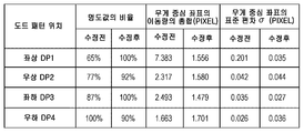
도 11은, 검출 화상 수정 유무에 있어서의 평가 결과를 비교하여 나타내는 표이다. 도 12는 복수회 측정한 무게 중심 좌표의 불균일을 검출 화상 수정 유무로 비교하여 나타낸 그래프이다. 도 11에 나타내는 바와 같이, 수정 전의 검출 화상의 각 도트 패턴(DP1∼DP4)에 대응하는 촬상 검출 화상 부분의 명도값(명도의 최대값)은, 65%, 77%, 87%, 100%라는 결과를 얻었다. 또한, 이 결과는 복수회(예를 들면 100회) 측정한 대표예를 나타내고 있다. 다음으로, 이 결과에 기초하여, 표준 편차(σ)의 값을, 좌상에 위치되는 도트 패턴(DP1) 및 좌하에 위치되는 도트 패턴(DP3)은 σ=9이고, 우상에 위치되는 도트 패턴(DP2) 및 우하에 위치되는 도트 패턴(DP4)은 σ=8로 하여 각 도트 패턴을 수정했다. 그 결과, 도 11에 나타내는 바와 같이, 수정 후의 검출 화상의 각 도트 패턴(DP1∼DP4)에 대응하는 촬상 검출 화상 부분의 명도값은, 100%, 92%, 100%, 90%라는 결과를 얻었다. 또한, 이 결과도 대응하는 대표예를 나타내고 있다.11 is a table showing comparison results of evaluation results in the presence or absence of corrected detected images. Fig. 12 is a graph showing the variation of the center-of-gravity coordinates measured a plurality of times by comparing the detected images with each other. As shown in Fig. 11, the brightness value (maximum value of brightness) of the image sensing detected image portion corresponding to each dot pattern DP1 to DP4 of the detected image before correction is 65%, 77%, 87%, and 100% Results were obtained. Further, this result shows a representative example measured plural times (for example, 100 times). Next, based on this result, it is assumed that the dot pattern DP1 positioned at the upper left and the dot pattern DP3 located at the lower left are? = 9 and the standard deviation? DP2) and the dot pattern DP4 located at the lower right are set to? = 8, and the dot patterns are corrected. As a result, as shown in Fig. 11, the brightness value of the image sensing detected image portion corresponding to each dot pattern DP1 to DP4 of the corrected detection image was 100%, 92%, 100%, and 90% . This result also represents a corresponding representative example.
또한, 도 12에 나타내는 바와 같이, 복수회(여기에서는 100회) 촬상하여 측정한 무게 중심 좌표의 불균일을, 수정 전에 비하여 작게 할 수 있었다. 특히, 수정 전의 명도값의 비율이 현저하게 낮았던 좌상에 위치되는 도트 패턴(DP1)의 결과를 보면 분명한 바와 같이, 비율이 크게 개선되어 있고, 4개의 도트 패턴 간의 불균일의 차이가 작아져 있는 것을 알 수 있다. 마찬가지로, 도 11에서 측정된 무게 중심 좌표의 이동량의 총합 및 무게 중심 좌표의 표준 편차(σ)도, 명도값의 비율이 현저하게 낮았던 좌상에 위치되는 도트 패턴(DP1)의 결과를 보면 분명한 바와 같이, 크게 개선되어 있고, 4개의 도트 패턴 간에서의 불균일의 차이가 작아져 있는 것을 알 수 있다.Further, as shown in Fig. 12, the unevenness of the center of gravity coordinates obtained by imaging and measuring a plurality of times (100 times in this case) can be made smaller than that before correction. Particularly, as is evident from the results of the dot pattern DP1 located at the upper left corner where the ratio of brightness values before correction was remarkably low, it was found that the ratio was greatly improved and the difference in unevenness among the four dot patterns was small . Similarly, the sum of the movement amounts of the center-of-gravity coordinates measured in Fig. 11 and the standard deviation (σ) of the center-of-gravity coordinates are also as shown in the result of the dot pattern DP1 located at the upper left, where the ratio of the brightness values was remarkably low , And it can be seen that the difference in non-uniformity among the four dot patterns is reduced.
이상과 같이, 각 도트 패턴에 대응하는 촬상 검출 화상 부분의 명도값이 허용 범위 내에 들어가 서로 거의 동일해지도록 수정함으로써, 각 점에서의 무게 중심 좌표의 추출 정밀도가 향상되고 있는 것을 확인할 수 있었다.As described above, it has been confirmed that the extraction precision of the center-of-gravity coordinates at each point is improved by correcting the brightness value of the image-sensing detected image portion corresponding to each dot pattern to fall within the allowable range and become almost equal to each other.
이상 설명한 바와 같이, 본 실시예에 따른 프로젝터에서는, 검출 화상의 검출 화상 부분인 도트 패턴에 대응하는 촬상 화상 중의 검출 화상 부분(촬상 검출 화상 부분)의 명도값이 허용 범위 내에 들어가 서로 거의 동일해지도록 검출 화상을 수정함으로써, 검출 화상의 검출 정밀도를 향상시킬 수 있다. 또한, 동일하게, 포커스 조정이 되어 있지 않아 포커스가 흐려져 있는 상태이거나, 키스톤 보정이 되어 있지 않아 투사 화상이 왜곡된 상태라도, 검출 화상의 검출 정밀도를 향상시킬 수 있다. 이 결과, 정밀도 좋게 추출된 검출 화상을 이용하여, 포커스 조정이나 키스톤 보정 등의 여러 가지의 조정을 정밀도 좋게 실행하는 것이 가능해진다.As described above, in the projector according to the present embodiment, the brightness value of the detected image portion (image sensing detected image portion) in the sensed image corresponding to the dot pattern which is the detected image portion of the detected image falls within the allowable range and becomes almost equal to each other By correcting the detected image, the detection accuracy of the detected image can be improved. Similarly, the detection accuracy of the detected image can be improved even when the focus is not adjusted and the focus is blurred or the projected image is distorted because the keystone correction is not performed. As a result, various adjustments such as focus adjustment and keystone correction can be performed with high precision using the detected image extracted with high accuracy.
C.변형예:C. Modifications:
또한, 본 발명은 상기한 실시예에 한정되는 것이 아니고, 본 발명의 범주 내에서 여러 가지의 형태로 실시하는 것이 가능하다.The present invention is not limited to the above-described embodiments, but can be implemented in various forms within the scope of the present invention.
(1) 변형예 1(1)
상기 실시예에서는, 검출 화상 부분인 도트 패턴의 생성에 있어서, 도 5에 나타낸 바와 같이 정규 분포 함수를 이용하여 결정한 배분값을 이용하여 각 단의 확률 밀도의 차이가 등간격이 되도록 설정함과 함께, 각 단의 명도값을 명도값의 비율이 등간격으로 작아지도록 설정하는 경우를 예로 설명했다. 그러나, 본 발명은 이것에 한정되는 것이 아니고, 정규 분포 함수 대신에 꺾임선 형상의 직선 함수나 2차 함수 등을 이용해도 좋다. 또한 각 단의 명도값을 등간격의 명도값의 비율대신에, 계조값이 등간격으로 작아지도록 설정해도 좋고, 계조값이나 비율을 등간격으로 하지 않아도 된다.In the above embodiment, in the generation of the dot pattern as the detected image portion, the distribution values determined using the normal distribution function as shown in Fig. 5 are used to set the difference in probability density at each end to be equal intervals , And the brightness value of each stage is set so that the ratio of the brightness value becomes equal to an equal interval. However, the present invention is not limited to this, and instead of the normal distribution function, a linear function or a quadratic function may be used. Alternatively, instead of the ratio of the brightness value of the equal interval, the brightness value of each stage may be set so that the gray level value becomes smaller at equal intervals, and the gray level value or the ratio may not be set at equal intervals.
또한, 상기 실시예에서는, 도트 패턴의 수정의 예로서, 표준 편차(σ)를 변경한 경우에 대해서 설명했지만, 실시예에서도 설명한 바와 같이, 도트 패턴 사이즈나, 계조 단수, 중심 영역의 명도값 등 여러 가지의 파라미터를 변경함으로써 실행하도록 해도 좋다.In the above embodiment, the description has been given of the case where the standard deviation? Is changed as an example of correction of the dot pattern. However, as described in the embodiment, the dot pattern size, the number of tones, Or by changing various parameters.
이상과 같이, 도트 패턴인 검출 화상 부분의 생성 및 수정은, 서로 상이한 명도값을 각각 갖는 복수의 영역을 포함하는 바와 같은 검출 화상 부분을 생성할 수 있고, 수정할 수 있으면, 어떠한 방법을 이용해도 좋다.As described above, any method can be used for generating and modifying the detected image portion which is a dot pattern, as long as it can generate a detected image portion including a plurality of regions each having a different brightness value from each other and can be modified .
(2) 변형예 2(2)
상기 실시예에서는, 도 3a 및 도 3b에 나타낸 바와 같이, 4개의 도트 패턴을 검출 화상 부분으로서 화상의 네 모퉁이에 배치한 검출 화상을 예로 설명했다. 그러나, 본 발명은 이것에 한정되는 것은 아니고 여러 가지의 검출 화상을 이용할 수 있다. 이하에서는 다른 검출 화상에 대해서 몇 가지 예시한다.In the above embodiment, as shown in Fig. 3A and Fig. 3B, a detection image in which four dot patterns are arranged at four corners of the image as the detected image portion has been described as an example. However, the present invention is not limited to this, and various detection images can be used. Hereinafter, some examples of other detected images will be exemplified.
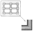
도 13a 및 도 13b는, 도트 패턴을 이용한 다른 검출 화상의 예를 나타내는 설명도이다. 도 13a는, 9개의 도트 패턴을 격자 형상으로 배치한 예이다. 도 13b는, 정방형의 정점에 배치된 4개의 도트 패턴을 1개의 블록으로 하여, 4개의 블록이 화상의 네 모퉁이에 배치한 예이다. 이들과 같이, 검출 화상 부분인 도트 패턴의 수나 위치 등 여러 가지 변경된 검출 화상이 이용될 수 있다.13A and 13B are explanatory views showing examples of another detected image using a dot pattern. 13A shows an example in which nine dot patterns are arranged in a lattice pattern. Fig. 13B is an example in which four dot patterns arranged at vertexes of a square are used as one block, and four blocks are arranged at four corners of the image. As in these cases, various modified detection images such as the number and position of the dot pattern as the detected image portion can be used.
도 14는, 도트 패턴이 아닌 다른 검출 화상 부분을 포함하는 검출 화상의 예를 나타내는 설명도이다. 도 14는, 격자 형상의 라인 화상을 나타낸다. 이 라인 화상은, 라인의 중심 영역의 명도값이 높고, 라인의 외측 영역의 명도값이 낮아지도록, 서로 상이한 명도값을 갖는 복수의 영역으로 구분되어 있다. 이 검출 화상의 경우에는, 원의 테두리로 나타난 부분을 검출 화상 부분으로 하면 좋다. 수정은, 라인의 폭, 계조 단수, 각 단의 폭, 중심 영역의 명도의 설정값 등을 변경함으로써 실행할 수 있다. 상술한 바와 같이, 검출 화상 부분은 도트 패턴에 한정되는 것이 아니고, 서로 상이한 명도값을 각각 갖는 복수의 영역을 포함하는 복수의 검출 화상 부분을 갖는 검출 화상이기만 하면, 여러 가지의 검출 화상이 이용될 수 있다.14 is an explanatory diagram showing an example of a detected image including a detected image portion other than the dot pattern. 14 shows a lattice-shaped line image. This line image is divided into a plurality of areas having different brightness values so that the brightness value of the central area of the line is high and the brightness value of the outside area of the line is low. In the case of this detected image, a portion indicated by a circle border may be used as the detected image portion. The correction can be performed by changing the width of the line, the number of gradations, the width of each end, the set value of the brightness of the center region, and the like. As described above, the detected image portion is not limited to the dot pattern, and if the detected image is a detection image having a plurality of detected image portions including a plurality of regions each having a different brightness value, .
(3) 변형예 3(3) Modification 3
도 15는, 복수의 프로젝터를 이용하여 피투사면에 화상을 서로 겹쳐 표시하는 구성에 대해서 나타내는 설명도이다. 또한, 도 15에서는 2대의 프로젝터(PJ1, PJ2)로부터의 투사 화상이 피투사면인 스크린(SC) 상에서 서로 겹쳐져 1개의 화상이 표시되는 경우를 예로 나타내고 있다. 2대의 프로젝터(PJ1, PJ2)의 구성은 실시예와 실질적으로 동일하다.Fig. 15 is an explanatory view showing a configuration in which images are superimposed on a projection surface using a plurality of projectors. Fig. In Fig. 15, the case where the projected images from the two projectors PJ1 and PJ2 overlap each other on the screen SC, which is a surface to be irradiated, and one image is displayed is shown. The configurations of the two projectors PJ1 and PJ2 are substantially the same as those of the embodiment.
복수의 프로젝터로부터의 투사 화상을 서로 겹쳐 1개의 화상을 표시하는 경우에 있어서, 각각의 화상을 정밀하게 서로 겹쳐 표시하기 위해서는, 검출 화상을 정밀도 좋게 추출하고, 검출 화상의 검출 화상 부분에 대응하는 촬상 검출 화상 부분의 무게 중심 좌표를 정밀도 좋게 구하는 것이 중요해진다. 도 15에 나타낸 예에서는, 실시예에서 설명한 프로젝터(PJ)와 동일한 구성을 갖는 2대의 프로젝터(PJ1, PJ2)를 이용하고 있기 때문에, 실시예에서 설명한 바와 같이, 각각의 프로젝터에 있어서 검출 화상을 정밀도 좋게 추출하여, 검출 화상의 검출 화상 부분에 대응하는 촬상 검출 화상 부분의 무게 중심 좌표를 정밀도 좋게 구하는 것이 가능해진다. 따라서, 각각의 화상의 서로 겹침의 정밀도를 향상시키는 것이 가능하다.In the case of displaying one image by superimposing projection images from a plurality of projectors on each other, in order to superimpose each image accurately, it is necessary to extract the detected image with high precision, It is important to obtain the center-of-gravity coordinates of the detected image portion with high accuracy. In the example shown in Fig. 15, since two projectors PJ1 and PJ2 having the same configuration as the projector PJ explained in the embodiment are used, as described in the embodiment, in each projector, The center of gravity of the center of gravity of the image sensing detected image portion corresponding to the detected image portion of the detected image can be obtained with high accuracy. Therefore, it is possible to improve the accuracy of overlapping each image.
또한, 제1 프로젝터(PJ1)와 제2 프로젝터(PJ2) 사이에서, 검출 화상을 변경하도록해도 좋다. 구성에 따르면, 스크린(SC)에 투사된 검출 화상을 용이하게 분리할 수 있어, 각각의 프로젝터에 있어서의 검출 화상의 추출이 용이해진다. 검출 화상의 변경에는, 도트 패턴의 배치 위치나 수를 변경하는 것이나, 검출 화상의 패턴 자체를, 예를 들면, 도 3a, 도 13a, 도 13b에 나타내는 도트 패턴과, 도 14에 나타내는 패턴과 같이, 변경하는 것 등, 여러 가지의 방법을 생각할 수 있다. 또한, 2대의 프로젝터에 한정되는 것이 아니고, 복수대의 프로젝터로부터의 투사 화상을 서로 겹쳐 1개의 화상을 표시하는 경우에 있어서 효과적이다.Further, the detected image may be changed between the first projector PJ1 and the second projector PJ2. According to the configuration, the detected image projected on the screen SC can be easily separated, and it is easy to extract the detected image in each projector. To change the detected image, it is possible to change the arrangement position and the number of dot patterns, or to change the pattern of the detected image itself, for example, as shown in Figs. 3A, 13A and 13B, , And a variety of methods can be considered. Furthermore, the present invention is not limited to two projectors, and is effective when projected images from a plurality of projectors overlap each other to display one image.
(4) 변형예 4(4)
상기 실시예에 있어서, 도 6a, 도 6b, 도 7a ~ 도 7c, 도 8a, 도 8b에서 설명한 수정값을 구하기 위한 방법이나 그에 이용한 수식은, 설명만을 위한 것으로, 이것에 한정되는 것이 아니다. 촬상 화상의 각 검출 화상 부분(촬상 검출 화상 부분)의 명도값이 허용 범위 내에 들어가 서로 거의 동일해질 수 있기만 하면 어느 방법이나 수식이 이용될 수 있다.In the above embodiment, the method for obtaining the correction value described in FIGS. 6A, 6B, 7A to 7C, 8A, and 8B and the formula used therein are for explanation only, and are not limited thereto. Any method or formula can be used so long as the brightness value of each detected image portion (image sensing detected image portion) of the sensed image falls within the permissible range and can be made substantially equal to each other.
(5) 변형예 5(5) Modification 5
상기 실시예에 있어서, 무게 중심 좌표의 산출은, 식 (11), 식 (12)를 이용한 것에 한정되는 것은 아니고, 여러 가지의 무게 중심 좌표의 산출 방법을 이용할 수 있다. 예를 들면, 경계값(th)보다도 큰 명도값을 갖는 화소의 좌표의 평균값으로 해도 좋다. 또한, 무게 중심 좌표 산출 대상 영역(Ag) 내에 위치된 화소의 좌표의 평균값을 적용하는 것이 가능하다.In the above embodiment, the calculation of the center-of-gravity coordinates is not limited to the calculation using the equations (11) and (12), but various calculation methods of the center-of-gravity coordinates can be used. For example, the average value of the coordinates of the pixel having the brightness value larger than the threshold value th may be used. It is also possible to apply the average value of the coordinates of the pixels located in the center-of-gravity coordinate calculation target area Ag.
(6) 변형예 6(6) Modification 6
상기 실시예에서는, 검출 화상 조정의 개시를 이용자가 입력 조작부(10)를 조작하여 지시함으로써 개시되는 것으로 하고 있다. 그러나, 본 발명은 이것에 한정되는 것이 아니고, 검출 화상 조정은 여러 가지의 타이밍으로 개시할 수 있다. 예를 들면, 프로젝터의 기동시에 자동으로 검출 화상 조정이 개시될 수 있다. 또한, 프로젝터의 상태가 정지 상태로부터 이동 상태로 천이하는 것을 움직임 검출부(60)에 의해 검출하여 자동으로 검출 화상 조정이 개시되도록 해도 좋다.In the above embodiment, the start of the detection image adjustment is started by the user operating the
(7) 변형예 7(7) Variation 7
상기 실시예의 검출 화상 조정 처리(도 2)에서는, 각 검출 화상 부분의 무게 중심 좌표를 구하여 처리를 종료하는 것으로 하여 설명하고 있지만, 예를 들면, 유저로부터의 종료 지시가 있을 때까지 대기하고, 이 대기하고 있는 동안에, 움직임 검출부에 의해 프로젝터의 움직임이 검출되어 설치 상태의 변화가 검출된 것이나, 프로젝터의 설정 조건이 변경된 것에 의해 검출 화상의 재조정이 필요하다고 판단된 경우에, 검출 화상의 조정을 다시 하도록 해도 좋다. 또한, 유저로부터의 종료 지시가 아니라, 일정 시간 검출 화상의 재조정이 필요하지 않았던 경우에 처리가 종료되도록 해도 좋다.In the detection image adjustment processing (Fig. 2) of the embodiment, the center of gravity coordinates of the detected image portions are obtained and the processing is terminated. However, for example, the processing waits until there is an end instruction from the user. When it is determined that the movement of the projector is detected by the motion detection unit and a change in the installation state is detected while it is waiting or when it is determined that the adjustment of the detected image is necessary due to the change in the setting condition of the projector, . In addition, the process may be terminated when it is not necessary to re-adjust the detected image for a predetermined time, instead of the end instruction from the user.
(8) 변형예 8(8) Modification 8
상기 실시예에서는, 프로젝터 내에 촬상부가 구비되는 경우를 예로 설명했다. 그러나, 프로젝터와는 별도로 촬상부를 구비할 수 있도록 해도 좋다. 이 경우에 있어서도, 프로젝터와는 별도로 구비된 촬상부에서 촬상되는 화상에 따라서 검출 화상이 수정될 수 있다. 따라서, 검출 화상을 정밀도 좋게 추출하여, 검출 화상의 검출 화상 부분에 대응하는 각 촬상 검출 화상 부분의 무게 중심 좌표를 정밀도 좋게 구하는 것이 가능해진다. 따라서, 화상의 서로 겹침의 정밀도를 향상시키는 것이 가능하다.In the above embodiment, the case where the image pickup unit is provided in the projector has been described as an example. However, the image pickup unit may be provided separately from the projector. Even in this case, the detected image can be corrected in accordance with the image picked up by the image pickup section provided separately from the projector. Therefore, it is possible to extract the detected image with high precision, and obtain the center-of-gravity coordinates of each imaging detection image portion corresponding to the detected image portion of the detected image with high accuracy. Therefore, it is possible to improve the accuracy of overlapping images.
(9) 변형예 9(9) Modification 9
상기 실시예에 있어서, 프로젝터(PJ)는, 투과형의 액정 패널을 이용한 액정 라이트 밸브(440)를 광변조 장치로서 이용하여, 조명 광학계(420)로부터의 빛을 화상광으로 변환하고 있다. 그러나, 디지털 마이크로 미러 디바이스(DMD: Digital Micro-Mirror Device)나, 반사형의 액정 패널 등을 광변조 장치로서 이용하도록 해도 좋다.In the above embodiment, the projector PJ uses a liquid crystal light valve 440 using a transmissive liquid crystal panel as an optical modulator, and converts light from the illumination
10 : 입력 조작부
20 : 제어 회로
30 : 화상 처리 동작 회로
40 : 화상 투사 광학계
50 : 촬상부
220 : 제어부
230 : 검출 화상 조정부
232 : 검출 화상 생성부
234 : 촬상 제어부
236 : 화상 해석부
238 : 무게 중심 좌표 검출부
260 : 정보 기억부
262 : 설정 정보 기억부
264 : 검출 화상 정보 기억부
266 : 촬상 화상 정보 기억부
320 : 입력 처리부
340 : 화상 표시 처리부
360 : 화상 메모리
380 : 라이트 밸브 구동부
420 : 조명 광학계
422 : 광원 램프
424 : 램프 구동부
440 : 액정 라이트 밸브
460 : 투사 광학계
462 : 투사 렌즈
464 : 렌즈 구동부
466 : 상태 검출부
PJ : 프로젝터
PJ1, PJ2 : 프로젝터
TP, TPa : 검출 화상
PP : 화상
DP : 도트 패턴
DP1∼DP4 : 도트 패턴(검출 화상 부분)
SDP1∼SDP4 : 촬상 검출 화상 부분
SC : 스크린(피투사면)10:
20: Control circuit
30: Image processing operation circuit
40: image projection optical system
50:
220:
230:
232: Detected image generating section
234:
236:
238: Center of gravity coordinate detector
260: Information storage unit
262: Setting information storage unit
264: Detected image information storage unit
266: Picked-up image information storage unit
320:
340: Image display processing unit
360: image memory
380: Light valve driving part
420: illumination optical system
422: Light source lamp
424:
440: liquid crystal light valve
460: Projection optical system
462: Projection lens
464:
466:
PJ: Projector
PJ1, PJ2: Projector
TP, TPa: Detected image
PP: burn
DP: dot pattern
DP1 to DP4: dot pattern (detected image portion)
SDP1 to SDP4:
SC: Screen
Claims (8)
상기 피투사면 상에 표시되는 투사 화상의 상태를 검출하기 위한 화상으로서, 복수의 검출 화상 부분을 포함하는 검출 화상을 생성하는 검출 화상 생성부를 구비하고,
상기 검출 화상 부분의 각각은, 서로 상이한 명도값을 각각 갖는 복수의 영역을 포함하고 있고,
상기 검출 화상 생성부는, 상기 피투사면 상에 투사된 상기 검출 화상을 촬상하여 얻어진 촬상 검출 화상에 포함되는 상기 검출 화상 부분의 명도의 최대값이 허용 범위내에 있도록, 생성하는 상기 검출 화상의 상기 검출 화상 부분의 각각의 명도 분포를 변경하는 것을 특징으로 하는 화상 처리 장치.An image processing apparatus used in a projector for projecting and displaying an image on a projection surface,
And a detected image generating unit that generates a detected image including a plurality of detected image portions as an image for detecting the state of a projected image displayed on the surface to be irradiated,
Wherein each of the detected image portions includes a plurality of regions each having a different brightness value,
The detected image generating section generates the detected image of the detected image of the detected image so that the maximum value of the brightness of the detected image portion included in the captured detection image obtained by imaging the detected image projected on the surface to be irradiated is within the allowable range, And changes the brightness distribution of each of the portions.
상기 검출 화상 생성부는, 상기 촬상 검출 화상에 포함되는 상기 검출 화상 부분 중, 어느 하나의 상기 촬상 검출 화상 부분의 명도값을 기준 명도값으로 하고, 상기 기준 명도값과 다른 검출 화상 부분의 명도값 사이의 관계에 기초하여, 상기 촬상 검출 화상에 포함되는 상기 검출 화상 부분의 명도의 최대값이 서로 대략 동일해지도록, 생성하는 상기 검출 화상의 상기 검출 화상 부분의 각각의 명도 분포를 변경하는 것을 특징으로 하는 화상 처리 장치.The method according to claim 1,
Wherein the detected image generating section sets the brightness value of any one of the detected image portions included in the captured detection image as a reference brightness value and sets the brightness value of the captured image portion as a reference brightness value, The brightness distribution of each of the detected image portions of the detected image to be generated is changed so that the maximum value of the brightness of the detected image portion included in the captured image is substantially equal to each other To the image processing apparatus.
상기 검출 화상 생성부는, 상기 검출 화상에 포함되는 상기 검출 화상 부분의 외형 사이즈와, 상기 검출 화상 부분에 포함되는 상기 영역의 각각의 폭과, 상기 검출 화상 부분의 명도의 최대값 중 적어도 하나를 변경함으로써, 생성하는 상기 검출 화상의 상기 검출 화상 부분의 각각의 명도 분포를 변경하는 것을 특징으로 하는 화상 처리 장치.3. The method according to claim 1 or 2,
Wherein the detected image generating unit changes at least one of an outer size of the detected image portion included in the detected image, a width of each of the regions included in the detected image portion, and a maximum value of the brightness of the detected image portion Thereby changing the brightness distribution of each of the detected image portions of the detected image to be generated.
상기 영역의 구분은, 미리 정한 함수에 기초하여 구해지는 것을 특징으로 하는 화상 처리 장치.4. The method according to any one of claims 1 to 3,
Wherein the division of the area is obtained on the basis of a predetermined function.
상기 함수는 가우스 분포 함수인 것을 특징으로 하는 화상 처리 장치.5. The method of claim 4,
Wherein the function is a Gaussian distribution function.
상기 투사 화상의 화질을 조정하는 투사 화상 조정부를 더 구비하고,
상기 투사 화상 조정부는, 상기 검출 화상을 이용한 처리에 기초하여, 상기 투사 화상의 포커스 조정과 키스톤 왜곡 보정을 포함하는 복수의 화질 조정 중, 적어도 하나의 화질 조정을 실행하는 것을 특징으로 하는 화상 처리 장치.6. The method according to any one of claims 1 to 5,
Further comprising a projected image adjusting section for adjusting an image quality of the projected image,
Wherein the projected image adjustment section executes at least one image quality adjustment among a plurality of image quality adjustments including focus adjustment of the projected image and keystone distortion correction based on processing using the detected image .
제1항 내지 제6항 중 어느 한 항에 기재된 화상 처리 장치와,
상기 피투사면 상에 투사된 상기 검출 화상을 촬상하는 촬상부와,
상기 화상 처리 장치로부터 출력된 화상 데이터에 기초하여, 상기 화상을 투사하는 투사부를 구비하는 것을 특징으로 하는 프로젝터.A projector for projecting and displaying an image on a projection surface,
An image processing apparatus comprising: the image processing apparatus according to any one of claims 1 to 6;
An imaging unit for imaging the detected image projected on the surface to be irradiated;
And a projection unit for projecting the image based on the image data output from the image processing apparatus.
(a) 상기 피투사면 상에 표시되는 투사 화상의 상태를 검출하기 위한 화상으로서, 복수의 검출 화상 부분을 포함하는 검출 화상을 생성하는 공정과,
(b) 상기 피투사면 상에 상기 검출 화상을 투사하는 공정을 구비하고,
상기 검출 화상 부분의 각각은, 서로 상이한 명도값을 각각 갖는 복수의 영역을 포함하고 있고,
상기 공정 (a)에서는,
상기 피투사면 상에 투사된 상기 검출 화상을 촬상하여 얻어진 촬상 검출 화상에 포함되는 상기 검출 화상 부분의 명도의 최대값이 허용 범위 내에 있도록, 생성하는 상기 검출 화상의 상기 검출 화상 부분의 각각의 명도 분포가 변경되는 것을 특징으로 하는 프로젝터의 제어 방법.
A projector control method for projecting and displaying an image on a projection surface,
(a) generating, as an image for detecting a state of a projected image displayed on the surface to be irradiated, a detected image including a plurality of detected image portions;
(b) projecting the detected image on the surface to be irradiated,
Wherein each of the detected image portions includes a plurality of regions each having a different brightness value,
In the step (a)
And the brightness distribution of each of the detected image portions of the detected image to be generated so that the maximum value of the brightness of the detected image portion included in the captured detection image obtained by picking up the detected image projected onto the surface to be irradiated is within the allowable range Is changed.
Applications Claiming Priority (3)
| Application Number | Priority Date | Filing Date | Title |
|---|---|---|---|
| JP2012063282A JP6089424B2 (en) | 2012-03-21 | 2012-03-21 | Image processing apparatus, projector, and projector control method |
| JPJP-P-2012-063282 | 2012-03-21 | ||
| PCT/JP2013/001880 WO2013140794A1 (en) | 2012-03-21 | 2013-03-19 | Image processing device, projector, and method of controlling projector |
Publications (2)
| Publication Number | Publication Date |
|---|---|
| KR20140139014A true KR20140139014A (en) | 2014-12-04 |
| KR101640096B1 KR101640096B1 (en) | 2016-07-15 |
Family
ID=48190564
Family Applications (1)
| Application Number | Title | Priority Date | Filing Date |
|---|---|---|---|
| KR1020147029358A KR101640096B1 (en) | 2012-03-21 | 2013-03-19 | Image processing device, projector, and method of controlling projector |
Country Status (9)
| Country | Link |
|---|---|
| US (1) | US9426436B2 (en) |
| EP (1) | EP2829068A1 (en) |
| JP (1) | JP6089424B2 (en) |
| KR (1) | KR101640096B1 (en) |
| CN (1) | CN103327274A (en) |
| IN (1) | IN2014DN08447A (en) |
| RU (1) | RU2596154C2 (en) |
| TW (1) | TWI566603B (en) |
| WO (1) | WO2013140794A1 (en) |
Families Citing this family (30)
| Publication number | Priority date | Publication date | Assignee | Title |
|---|---|---|---|---|
| JP5924020B2 (en) * | 2012-02-16 | 2016-05-25 | セイコーエプソン株式会社 | Projector and projector control method |
| JP6289003B2 (en) * | 2013-09-26 | 2018-03-07 | キヤノン株式会社 | Information processing apparatus, control method therefor, and program |
| CN104657971B (en) * | 2013-11-25 | 2018-10-12 | 联想(北京)有限公司 | The control method of a kind of electronic equipment and its working condition, control unit |
| JP6618249B2 (en) * | 2014-02-18 | 2019-12-11 | パナソニック インテレクチュアル プロパティ コーポレーション オブ アメリカPanasonic Intellectual Property Corporation of America | Projection system and semiconductor integrated circuit |
| JP2015206950A (en) * | 2014-04-22 | 2015-11-19 | ソニー株式会社 | Information processing device, information processing method, program, adjustment device and image display system |
| JP6471438B2 (en) * | 2014-09-17 | 2019-02-20 | 株式会社リコー | Output control device, output control system, and output control program |
| JP6590313B2 (en) | 2015-09-08 | 2019-10-16 | パナソニックIpマネジメント株式会社 | Lighting device and lighting system |
| JP6679950B2 (en) * | 2016-01-26 | 2020-04-15 | セイコーエプソン株式会社 | Projector and projector control method |
| JP6631281B2 (en) * | 2016-02-03 | 2020-01-15 | セイコーエプソン株式会社 | Interactive projector and its auto-calibration execution method |
| CN106094405B (en) | 2016-06-03 | 2017-11-21 | 海信集团有限公司 | Projected picture correcting method, device and projector |
| JP6460088B2 (en) * | 2016-12-14 | 2019-01-30 | カシオ計算機株式会社 | Projection apparatus, projection method, and program |
| JP2018124441A (en) * | 2017-02-01 | 2018-08-09 | キヤノン株式会社 | System, information processing apparatus, information processing method, and program |
| CN110313176A (en) * | 2017-02-27 | 2019-10-08 | 索尼公司 | Image processing apparatus, method and program |
| JP2018160803A (en) * | 2017-03-23 | 2018-10-11 | セイコーエプソン株式会社 | Projector and method for controlling projector |
| JP6766720B2 (en) * | 2017-03-27 | 2020-10-14 | カシオ計算機株式会社 | Image processing device, image processing method and image processing program |
| JP7218721B2 (en) | 2017-03-28 | 2023-02-07 | ソニーグループ株式会社 | Image processing device and method |
| CN109104596B (en) | 2017-06-21 | 2021-02-26 | 中强光电股份有限公司 | Projection system and correction method of display image |
| CN107990980A (en) * | 2017-12-25 | 2018-05-04 | 深圳深索智能科技有限公司 | A kind of projector brightness on-line detecting system |
| JP6642610B2 (en) * | 2018-03-22 | 2020-02-05 | カシオ計算機株式会社 | Projection control device, projection device, projection control method, and program |
| JP7228966B2 (en) * | 2018-06-29 | 2023-02-27 | キヤノン株式会社 | Image processing device and its control method and program |
| CN111526343B (en) * | 2019-02-01 | 2022-03-01 | 中国电影器材有限责任公司 | Digital film projection method and system |
| US10890442B1 (en) * | 2019-12-26 | 2021-01-12 | Himax Technologies Limited | Structured light projector and method for structured light projection using the same |
| US11297289B2 (en) * | 2019-12-26 | 2022-04-05 | Himax Technologies Limited | Structured light projector |
| CN111010556B (en) * | 2019-12-27 | 2022-02-11 | 成都极米科技股份有限公司 | Method and device for projection bi-directional defocus compensation and readable storage medium |
| JP2023017206A (en) * | 2021-07-26 | 2023-02-07 | セイコーエプソン株式会社 | Method for controlling projector, and projector |
| CN113727083B (en) * | 2021-09-22 | 2023-01-24 | 歌尔科技有限公司 | Projector brightness adjusting method, projector brightness adjusting device and computer readable storage medium |
| CN113947602B (en) * | 2021-12-21 | 2022-03-18 | 山东信通电子股份有限公司 | Image brightness detection method and device |
| CN116456064A (en) * | 2022-01-10 | 2023-07-18 | 中强光电股份有限公司 | Focusing identification method and focusing identification system thereof |
| CN114833455B (en) * | 2022-05-23 | 2024-02-23 | 荣烯新材(北京)科技有限公司 | Method, device and application for carrying out unordered micro-modeling on roller surface of roller by femtosecond laser |
| CN116504163B (en) * | 2023-06-30 | 2023-08-29 | 深圳市木兰轩科技有限公司 | LED display screen operation monitoring and early warning system |
Citations (5)
| Publication number | Priority date | Publication date | Assignee | Title |
|---|---|---|---|---|
| JPH0715692A (en) * | 1993-06-24 | 1995-01-17 | Matsushita Electric Ind Co Ltd | Picture correction device for projection type display |
| JP2005159426A (en) | 2003-11-20 | 2005-06-16 | Nec Viewtechnology Ltd | Projector with automatic trapezoidal distortion correcting means |
| JP2007166271A (en) * | 2005-12-14 | 2007-06-28 | Seiko Epson Corp | Projection system and projector |
| US20110018897A1 (en) * | 2008-01-11 | 2011-01-27 | Takayuki Uchiyama | Projector |
| JP2011176629A (en) | 2010-02-24 | 2011-09-08 | Sanyo Electric Co Ltd | Controller and projection type video display device |
Family Cites Families (40)
| Publication number | Priority date | Publication date | Assignee | Title |
|---|---|---|---|---|
| KR0134160B1 (en) * | 1993-03-17 | 1998-04-22 | 모리시타 요이찌 | Image correction apparatus |
| EP0703714A3 (en) | 1994-09-20 | 1997-09-03 | Matsushita Electric Ind Co Ltd | Image display position detecting apparatus and image correction apparatus |
| JPH08317431A (en) * | 1995-05-23 | 1996-11-29 | Matsushita Electric Ind Co Ltd | Signal generator, position detector and image correction device |
| JPH09198206A (en) | 1996-01-18 | 1997-07-31 | Ricoh Co Ltd | Network control system |
| US6061102A (en) | 1997-10-10 | 2000-05-09 | Hughes-Jvc Technology Corporation | Automatic shading in an LCLV projector |
| US6292171B1 (en) | 1999-03-31 | 2001-09-18 | Seiko Epson Corporation | Method and apparatus for calibrating a computer-generated projected image |
| JP2001175576A (en) | 1999-10-04 | 2001-06-29 | Canon Inc | Device, system and method for processing information, and storage medium |
| JP2001255974A (en) | 2000-03-13 | 2001-09-21 | Canon Inc | Device and method for processing information |
| CN1196009C (en) | 2000-05-31 | 2005-04-06 | 精工爱普生株式会社 | Projector and projection display system and method and recorded medium |
| JP2002057964A (en) | 2000-05-31 | 2002-02-22 | Seiko Epson Corp | Projector and projection display system, and method for it and recording medium |
| JP2002116500A (en) * | 2000-10-05 | 2002-04-19 | Olympus Optical Co Ltd | Image projection/display device |
| JP3893922B2 (en) | 2000-10-18 | 2007-03-14 | セイコーエプソン株式会社 | Lens evaluation method and lens evaluation apparatus |
| RU2248025C2 (en) * | 2002-07-09 | 2005-03-10 | Марков Валерий Николаевич | Light diode projector and method for presenting information on display |
| JP2004221716A (en) * | 2003-01-10 | 2004-08-05 | Sony Corp | Position adjustment apparatus for optical modulator and position adjustment method for optical modulator |
| JP3844075B2 (en) * | 2003-01-17 | 2006-11-08 | セイコーエプソン株式会社 | Image processing system, projector, program, information storage medium, and image processing method |
| JP3871061B2 (en) * | 2003-03-25 | 2007-01-24 | セイコーエプソン株式会社 | Image processing system, projector, program, information storage medium, and image processing method |
| US7274382B2 (en) | 2003-07-16 | 2007-09-25 | Plut William J | Customizable background sizes and controls for changing background size |
| JP4055010B2 (en) * | 2003-09-26 | 2008-03-05 | セイコーエプソン株式会社 | Image processing system, projector, program, information storage medium, and image processing method |
| JP3852455B2 (en) * | 2004-03-19 | 2006-11-29 | セイコーエプソン株式会社 | Projector and pattern image display method |
| JP3925521B2 (en) | 2004-08-19 | 2007-06-06 | セイコーエプソン株式会社 | Keystone correction using part of the screen edge |
| JP4126564B2 (en) * | 2005-02-14 | 2008-07-30 | セイコーエプソン株式会社 | Image processing system, projector, program, information storage medium, and image processing method |
| JP4085283B2 (en) * | 2005-02-14 | 2008-05-14 | セイコーエプソン株式会社 | Image processing system, projector, program, information storage medium, and image processing method |
| JP4340915B2 (en) * | 2006-02-01 | 2009-10-07 | ソニー株式会社 | Captured image signal distortion correction method, captured image signal distortion correction apparatus, imaging method, and imaging apparatus |
| US7893393B2 (en) | 2006-04-21 | 2011-02-22 | Mersive Technologies, Inc. | System and method for calibrating an image projection system |
| JP4270264B2 (en) * | 2006-11-01 | 2009-05-27 | セイコーエプソン株式会社 | Image correction apparatus, projection system, image correction method, image correction program, and recording medium |
| JP5110912B2 (en) * | 2007-02-28 | 2012-12-26 | 日本放送協会 | Image projection system and image projection method |
| JP5273008B2 (en) * | 2009-10-16 | 2013-08-28 | 株式会社ニコン | Projector and projected image correction program |
| US8659585B2 (en) * | 2009-10-16 | 2014-02-25 | Nikon Corporation | Projector apparatus and projection image correcting program product |
| JP5495025B2 (en) | 2009-12-22 | 2014-05-21 | ソニー株式会社 | Image processing apparatus and method, and program |
| US8928554B2 (en) * | 2010-01-20 | 2015-01-06 | Ic Media Technology, Inc. | Mobile image display system |
| CA2739136A1 (en) * | 2010-05-10 | 2011-11-10 | Xpand, Inc. | 3d projector |
| JP5744418B2 (en) * | 2010-05-18 | 2015-07-08 | キヤノン株式会社 | Projection apparatus and projection method |
| JP5527049B2 (en) * | 2010-06-30 | 2014-06-18 | セイコーエプソン株式会社 | Light emitting device and projector |
| US8804504B1 (en) * | 2010-09-16 | 2014-08-12 | F5 Networks, Inc. | System and method for reducing CPU load in processing PPP packets on a SSL-VPN tunneling device |
| KR101439412B1 (en) * | 2010-11-22 | 2014-09-11 | 한국전자통신연구원 | Method of segmenting lesions in images |
| JP2012178674A (en) * | 2011-02-25 | 2012-09-13 | Sanyo Electric Co Ltd | Projection type video display device |
| JP5834615B2 (en) | 2011-08-18 | 2015-12-24 | 株式会社リコー | PROJECTOR, ITS CONTROL METHOD, ITS PROGRAM, AND RECORDING MEDIUM CONTAINING THE PROGRAM |
| JP5807489B2 (en) * | 2011-09-28 | 2015-11-10 | カシオ計算機株式会社 | Image processing apparatus, image processing method, and program |
| JP6056159B2 (en) * | 2012-03-08 | 2017-01-11 | セイコーエプソン株式会社 | Projector and method of processing image in projector |
| JP6089461B2 (en) * | 2012-06-22 | 2017-03-08 | セイコーエプソン株式会社 | Projector, image display system, and projector control method |
-
2012
- 2012-03-21 JP JP2012063282A patent/JP6089424B2/en not_active Expired - Fee Related
-
2013
- 2013-03-18 TW TW102109575A patent/TWI566603B/en not_active IP Right Cessation
- 2013-03-19 WO PCT/JP2013/001880 patent/WO2013140794A1/en active Application Filing
- 2013-03-19 US US14/381,421 patent/US9426436B2/en active Active
- 2013-03-19 RU RU2014142252/07A patent/RU2596154C2/en not_active IP Right Cessation
- 2013-03-19 KR KR1020147029358A patent/KR101640096B1/en active IP Right Grant
- 2013-03-19 EP EP13718911.4A patent/EP2829068A1/en not_active Ceased
- 2013-03-20 CN CN2013100906168A patent/CN103327274A/en active Pending
-
2014
- 2014-10-09 IN IN8447DEN2014 patent/IN2014DN08447A/en unknown
Patent Citations (5)
| Publication number | Priority date | Publication date | Assignee | Title |
|---|---|---|---|---|
| JPH0715692A (en) * | 1993-06-24 | 1995-01-17 | Matsushita Electric Ind Co Ltd | Picture correction device for projection type display |
| JP2005159426A (en) | 2003-11-20 | 2005-06-16 | Nec Viewtechnology Ltd | Projector with automatic trapezoidal distortion correcting means |
| JP2007166271A (en) * | 2005-12-14 | 2007-06-28 | Seiko Epson Corp | Projection system and projector |
| US20110018897A1 (en) * | 2008-01-11 | 2011-01-27 | Takayuki Uchiyama | Projector |
| JP2011176629A (en) | 2010-02-24 | 2011-09-08 | Sanyo Electric Co Ltd | Controller and projection type video display device |
Also Published As
| Publication number | Publication date |
|---|---|
| TWI566603B (en) | 2017-01-11 |
| TW201345255A (en) | 2013-11-01 |
| RU2014142252A (en) | 2016-05-20 |
| US9426436B2 (en) | 2016-08-23 |
| RU2596154C2 (en) | 2016-08-27 |
| JP6089424B2 (en) | 2017-03-08 |
| KR101640096B1 (en) | 2016-07-15 |
| WO2013140794A1 (en) | 2013-09-26 |
| EP2829068A1 (en) | 2015-01-28 |
| CN103327274A (en) | 2013-09-25 |
| JP2013195741A (en) | 2013-09-30 |
| US20150103257A1 (en) | 2015-04-16 |
| IN2014DN08447A (en) | 2015-05-08 |
Similar Documents
| Publication | Publication Date | Title |
|---|---|---|
| KR101640096B1 (en) | Image processing device, projector, and method of controlling projector | |
| KR101640090B1 (en) | Image processing device, projector, and method of controlling projector | |
| CN100529952C (en) | Image processing system, projector and image processing method | |
| KR100602622B1 (en) | Image processing system, projector, information storage medium and image processing method | |
| CN100470358C (en) | Image processing system, projector,and image processing method | |
| US9215431B2 (en) | Image processing apparatus, projector and control method of projector | |
| JP5251202B2 (en) | Distortion correction method for projected image of projector and projector | |
| JP2013197918A5 (en) | ||
| US9383635B2 (en) | Image processing device, projector, and image processing method | |
| TW201626351A (en) | Luminance level inspection equipment and luminance level inspection method | |
| JP7434487B2 (en) | Image processing device, projection system, image processing method, and image processing program | |
| JP2010288062A (en) | Projector, program, information storage medium, and image projection method | |
| JP5110260B2 (en) | Projector, program, information storage medium, and image distortion correction method | |
| JP2016014712A (en) | Shading correction value calculation device and shading correction value calculation method | |
| JP2019169915A (en) | Projection control device, projection apparatus, projection method and program | |
| JP5200599B2 (en) | Screen, optical characteristic measuring system, and optical characteristic measuring method | |
| JP2022077773A (en) | Projection control unit, image projection system, method for actuating projection control unit, and program |
Legal Events
| Date | Code | Title | Description |
|---|---|---|---|
| A201 | Request for examination | ||
| E902 | Notification of reason for refusal | ||
| E701 | Decision to grant or registration of patent right | ||
| GRNT | Written decision to grant | ||
| FPAY | Annual fee payment |
Payment date: 20190619 Year of fee payment: 4 |