KR20140133367A - Method and apparatus for transmitting reference signal in wireless communication system - Google Patents
Method and apparatus for transmitting reference signal in wireless communication system Download PDFInfo
- Publication number
- KR20140133367A KR20140133367A KR1020130053460A KR20130053460A KR20140133367A KR 20140133367 A KR20140133367 A KR 20140133367A KR 1020130053460 A KR1020130053460 A KR 1020130053460A KR 20130053460 A KR20130053460 A KR 20130053460A KR 20140133367 A KR20140133367 A KR 20140133367A
- Authority
- KR
- South Korea
- Prior art keywords
- csi
- special subframe
- pattern
- mapped
- ofdm
- Prior art date
Links
Images


Classifications
-
- H—ELECTRICITY
- H04—ELECTRIC COMMUNICATION TECHNIQUE
- H04L—TRANSMISSION OF DIGITAL INFORMATION, e.g. TELEGRAPHIC COMMUNICATION
- H04L5/00—Arrangements affording multiple use of the transmission path
- H04L5/14—Two-way operation using the same type of signal, i.e. duplex
- H04L5/1469—Two-way operation using the same type of signal, i.e. duplex using time-sharing
-
- H—ELECTRICITY
- H04—ELECTRIC COMMUNICATION TECHNIQUE
- H04L—TRANSMISSION OF DIGITAL INFORMATION, e.g. TELEGRAPHIC COMMUNICATION
- H04L25/00—Baseband systems
- H04L25/02—Details ; arrangements for supplying electrical power along data transmission lines
- H04L25/0202—Channel estimation
- H04L25/0224—Channel estimation using sounding signals
-
- H—ELECTRICITY
- H04—ELECTRIC COMMUNICATION TECHNIQUE
- H04L—TRANSMISSION OF DIGITAL INFORMATION, e.g. TELEGRAPHIC COMMUNICATION
- H04L27/00—Modulated-carrier systems
- H04L27/26—Systems using multi-frequency codes
- H04L27/2601—Multicarrier modulation systems
-
- H—ELECTRICITY
- H04—ELECTRIC COMMUNICATION TECHNIQUE
- H04L—TRANSMISSION OF DIGITAL INFORMATION, e.g. TELEGRAPHIC COMMUNICATION
- H04L27/00—Modulated-carrier systems
- H04L27/26—Systems using multi-frequency codes
- H04L27/2601—Multicarrier modulation systems
- H04L27/2602—Signal structure
- H04L27/2605—Symbol extensions, e.g. Zero Tail, Unique Word [UW]
- H04L27/2607—Cyclic extensions
-
- H—ELECTRICITY
- H04—ELECTRIC COMMUNICATION TECHNIQUE
- H04L—TRANSMISSION OF DIGITAL INFORMATION, e.g. TELEGRAPHIC COMMUNICATION
- H04L5/00—Arrangements affording multiple use of the transmission path
- H04L5/003—Arrangements for allocating sub-channels of the transmission path
- H04L5/0048—Allocation of pilot signals, i.e. of signals known to the receiver
-
- H—ELECTRICITY
- H04—ELECTRIC COMMUNICATION TECHNIQUE
- H04L—TRANSMISSION OF DIGITAL INFORMATION, e.g. TELEGRAPHIC COMMUNICATION
- H04L5/00—Arrangements affording multiple use of the transmission path
- H04L5/003—Arrangements for allocating sub-channels of the transmission path
- H04L5/0078—Timing of allocation
- H04L5/0082—Timing of allocation at predetermined intervals
-
- H—ELECTRICITY
- H04—ELECTRIC COMMUNICATION TECHNIQUE
- H04W—WIRELESS COMMUNICATION NETWORKS
- H04W88/00—Devices specially adapted for wireless communication networks, e.g. terminals, base stations or access point devices
- H04W88/08—Access point devices
-
- H—ELECTRICITY
- H04—ELECTRIC COMMUNICATION TECHNIQUE
- H04L—TRANSMISSION OF DIGITAL INFORMATION, e.g. TELEGRAPHIC COMMUNICATION
- H04L5/00—Arrangements affording multiple use of the transmission path
- H04L5/0001—Arrangements for dividing the transmission path
- H04L5/0014—Three-dimensional division
- H04L5/0023—Time-frequency-space
Landscapes
- Engineering & Computer Science (AREA)
- Signal Processing (AREA)
- Computer Networks & Wireless Communication (AREA)
- Power Engineering (AREA)
- Mobile Radio Communication Systems (AREA)
Abstract
A method and apparatus for transmitting a reference signal in a wireless communication system are provided. A base station (BS) generates a channel state information (CSI) reference signal (RS) sequence and transmits the generated CSI-RS sequence to a CSI-RS Maps to at least one resource element of a special subframe in a time division duplex (TDD) frame according to a pattern. The base station transmits an orthogonal frequency division multiplexing (OFDM) signal generated based on the mapped CSI-RS sequence to the UE. At this time, the CSI-RS pattern is determined according to the configuration of the special subframe and the cyclic prefix (CP).
Description
BACKGROUND OF THE
The universal mobile telecommunications system (UMTS) is a third generation (3rd) mobile communication system operating on wideband code division multiple access (WCDMA) based on European systems such as global system for mobile communications (GSM) and general packet radio services generation asynchronous mobile communication system. Long-term evolution (LTE) and LTE-advanced (LTE-advanced) are being discussed by the 3rd generation partnership project (3GPP), which standardized UMTS as a 4th generation mobile communication system.
Component carriers (CCs) used in a conventional multiple carrier system emphasize the versatility of the physical layer, and redundancy of control areas and common signal overhead exist. Therefore, there is a problem that resources for the data signal are reduced and there is unnecessary loss in terms of spectrum efficiency. Accordingly, in order to efficiently operate a multi-carrier system, introduction of a new carrier type (NCT) constituting a multi-carrier system is required. In the NCT, a reference signal (RS) for downlink control channel or channel estimation is used in comparison with a conventional carrier type (LCT) Can be removed or reduced. This is to obtain maximum data transmission efficiency. The existing conventional carrier wave type (LCT) is also called a backward compatible carrier type (BCCT) by distinguishing it from the NCT.
The NCT may include a non-standalone NCT and a standalone NCT. A non-exclusive NCT is an NCT that can not exist in a single cell form and can exist in the form of a secondary serving cell (SCell) when a primary cell (PCell) exists. On the other hand, a single NCT is an NCT that can exist in a single cell form. For example, a standalone NCT can exist in the form of a PCell. In a single NCT and a non-exclusive NCT, a cell-specific RS (CSRS) may not be transmitted. Accordingly, the existing control channel (PDCCH), the physical HARQ indicator channel (PHICH), and the physical control format indicator channel (PCFICH), which are control channels based on the CRS, can be removed or replaced with other types of channels.
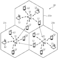
1 shows an example of a communication system in which a high power node and a low power node are arranged.
In a next generation communication system such as 3GPP LTE-A, as shown in FIG. 1, a macro cell based on a high-power node (F1) as well as a small cell based on a low- And F2 in order to provide wireless communication services indoors and outdoors.
Small cells aim to increase spectral efficiency with efficient deployment and operation. The small cell can be considered both in the frequency band F1 which is the coverage of the macro cell and in the frequency band F2 other than the coverage of the macro cell. In addition, the small cells can be provided both in an indoor environment (shown in a rectangular parallelepiped in Fig. 1) and in an outdoor environment (shown in Fig. 1, shown in a rectangular parallelepiped). In addition, an ideal or non-ideal backhaul network may be supported between macrocells and small cells, and / or between small cells. And small cells can be provided in both a low density sparse deployment environment and / or a dense deployment environment.
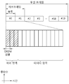
Table 1 shows the configuration of a special subframe in the time division duplex (TDD) frame of 3GPP LTE.

Referring to Table 1, the configuration of the special subframe in the TDD frame is composed of 9 in the normal CP (cyclic prefix) and 7 in the extended CP. Among the orthogonal frequency division multiplexing (OFDM) symbols of a particular subframe (DwPTS, guard period, etc.), 0, 1, 2, 3, 4, 5, 6, 7, 8, 1, 1), (10, 3, 1), (11, 2, 1), (12, 1, 1) (3, 9, 2), (9, 3, 2), (10, 2, 2), (11, 1, 2), (6, 6, 2). In the case of the extended CP, the number of OFDM symbols for the (DwPTS, guard period, UpPTS) of the twelve OFDM symbols of one special subframe is 0, 1, 2, 3, 4, 5, (8, 3, 1), (9, 2, 1), (10, 1, 1), (3, 7, 2) , 1, 2), (5, 5, 2).
In a wireless communication system, it is necessary to estimate an uplink channel or a downlink channel for data transmission / reception, system synchronization acquisition, channel information feedback, and the like. In wireless communication systems, fading occurs due to multipath time delay. The process of recovering a transmission signal by compensating for signal distortion caused by a sudden change in the environment due to fading is called channel estimation. It is also necessary to measure the channel state of a cell or another cell to which the UE belongs. For channel estimation or channel state measurement, channel estimation is generally performed using a reference signal that the transceiver knows.
A channel state information (CSI) reference signal (RS) is used for channel estimation for a PDSCH (physical downlink shared channel) of the LTE-A terminal. The CSI-RS is relatively sparse in the frequency domain or the time domain, and can be punctured in a normal subframe or a data region of a multimedia broadcast and multicast single frequency network (MBSFN) subframe. A channel quality indicator (CQI), a precoding matrix indicator (PMI), and a rank indicator (RI) may be reported from the terminal, if necessary, through the estimation of the CSI.
Currently, the CSI-RS in 3GPP LTE-A is not transmitted in the special subframe of the TDD frame. However, considering the future NCT or small cell environment, the transmission of the CSI-RS may also be required in the special subframe of the TDD frame. Thus, there is a need for a method of mapping and transmitting a CSI-RS to a resource element in a special sub-frame of a TDD frame.
It is a technical object of the present invention to provide a method and apparatus for transmitting a reference signal in a wireless communication system. The present invention provides a method and apparatus for transmitting a channel state information (CSI) reference signal (RS) in a special subframe in a time division duplex (TDD) frame. Also, in the special subframe in the TDD frame, considering the position of the demodulation reference signal (DMRS) which is changed based on the number of orthogonal frequency division multiplexing (OFDM) symbols for the DwPTS, A method and apparatus are provided for mapping to resource elements.
A method of transmitting a reference signal by a base station (BS) in a wireless communication system is provided. The method includes generating a channel state information (CSI) reference signal (RS) sequence, generating the generated CSI-RS sequence according to a CSI-RS pattern using a modulation symbol, Mapping at least one resource element of a special subframe in a time division duplex (TDD) frame to an orthogonal frequency division multiplexing (OFDM) signal generated based on the mapped CSI- Wherein the CSI-RS pattern is determined according to a configuration of the special subframe and a cyclic prefix (CP).
In another aspect, a base station (BS) is provided in a wireless communication system. The base station includes a reference signal generator configured to generate a channel state information (RS) reference signal sequence, a CSI-RS sequence generator configured to generate the CSI-RS sequence using a modulation symbol, A resource mapper configured to map to at least one resource element of a special subframe in a time division duplex (TDD) frame according to the -RS pattern, and a resource mapper configured to map an orthogonal OFDM symbol based on the mapped CSI- frequency division multiplexing (CSI) signal to a mobile station, and the CSI-RS pattern is determined according to a configuration of a special subframe and a cyclic prefix (CP).
In yet another aspect, a method is provided for performing channel estimation by a mobile station (MS) in a wireless communication system. The method includes receiving an orthogonal frequency division multiplexing (OFDM) signal generated based on a channel state information (CSI) reference signal sequence (RS), demodulating the received OFDM signal, Wherein the CSI-RS sequence comprises at least one resource of a special subframe in a time division duplex (TDD) frame according to a CSI-RS pattern using a modulation symbol, Element, and the CSI-RS pattern is determined according to a configuration of a special subframe and a cyclic prefix (CP).
In another aspect, a mobile station (MS) is provided in a wireless communication system. The UE includes a receiver configured to receive an orthogonal frequency division multiplexing (OFDM) signal generated based on a channel state information (CSI) reference signal sequence (RS), and a receiver configured to demodulate the received OFDM signal, Wherein the CSI-RS sequence is a special subframe in a time division duplex (TDD) frame according to a CSI-RS pattern using a modulation symbol, , And the CSI-RS pattern is determined according to a configuration of a special subframe and a cyclic prefix (CP).
It is possible to efficiently transmit the CSI-RS in the special subframe in the TDD frame.
1 shows an example of a communication system in which a high power node and a low power node are arranged.
2 shows a wireless communication system to which an embodiment of the present invention may be applied.
3 shows a structure of a radio frame in 3GPP LTE.
FIG. 4 shows an example of a resource grid for one downlink slot.
5 shows an example of a CSI-RS configuration and a CSI-RS pattern according to the number of CSI-RS antenna ports in a general CP.
6 shows an example of a CSI-RS configuration and a CSI-RS pattern according to the number of CSI-RS antenna ports in an extended CP.
Figure 7 shows the mapping of DMRSs in a general CP.
8 shows the mapping of the DMRS in the extended CP.
FIG. 9 shows a CSI-RS pattern when a CSI-RS pattern used in a normal subframe is directly used in a special subframe using a normal CP.
FIG. 10 shows a CSI-RS pattern when a CSI-RS pattern used in a normal subframe is directly used in a special subframe using an extended CP.
11 shows an example of a CSI-RS pattern configured according to a reference signal transmission method according to an embodiment of the present invention.
12 shows another example of a CSI-RS pattern configured according to a reference signal transmission method according to an embodiment of the present invention.
13 shows another example of a CSI-RS pattern configured according to a reference signal transmission method according to an embodiment of the present invention.
FIG. 14 shows another example of a CSI-RS pattern configured according to a reference signal transmission method according to an embodiment of the present invention.
15 shows another example of a CSI-RS pattern configured according to a reference signal transmission method according to an embodiment of the present invention.
16 shows another example of a CSI-RS pattern configured according to a reference signal transmission method according to an embodiment of the present invention.
17 shows another example of a CSI-RS pattern configured according to a reference signal transmission method according to an embodiment of the present invention.
18 shows another example of a CSI-RS pattern configured according to a reference signal transmission method according to an embodiment of the present invention.
19 shows an embodiment of a reference signal transmission method according to an embodiment of the present invention.
20 is a block diagram of a wireless communication system in which an embodiment of the present invention is implemented.
Hereinafter, some embodiments will be described in detail with reference to exemplary drawings. It should be noted that, in adding reference numerals to the constituent elements of the drawings, the same constituent elements are denoted by the same reference symbols as possible even if they are shown in different drawings. In the following description of the embodiments of the present invention, a detailed description of known functions and configurations incorporated herein will be omitted when it may make the subject matter of the present disclosure rather unclear.
The present invention will be described with reference to a communication network. The work performed in the communication network may be performed in a process of controlling the network and transmitting data by a system (e.g., a base station) that manages the communication network, The work can be done.
The following description is to be understood as illustrative and non-limiting, such as code division multiple access (CDMA), frequency division multiple access (FDMA), time division multiple access (TDMA), orthogonal frequency division multiple access (OFDMA), single carrier frequency division multiple access And can be used in various wireless communication systems. CDMA can be implemented with radio technology such as universal terrestrial radio access (UTRA) or CDMA2000. TDMA can be implemented with wireless technologies such as global system for mobile communications (GSM) / general packet radio service (GPRS) / enhanced data rates for GSM evolution (EDGE). OFDMA can be implemented with wireless technologies such as IEEE (Institute of Electrical and Electronics Engineers) 802.11 (Wi-Fi), IEEE 802.16 (WiMAX), IEEE 802-20, and evolved UTRA (E-UTRA). IEEE 802.16m is an evolution of IEEE 802.16e, providing backward compatibility with systems based on IEEE 802.16e. UTRA is part of the universal mobile telecommunications system (UMTS). 3GPP (3rd Generation Partnership Project) LTE (Long Term Evolution) is a part of E-UMTS (evolved UMTS) using evolved-UMTS terrestrial radio access (E-UTRA). It adopts OFDMA in downlink and SC -FDMA is adopted. LTE-A (advanced) is the evolution of 3GPP LTE.
For the sake of clarity, LTE-A is mainly described, but the technical idea of the present invention is not limited thereto.
2 shows a wireless communication system to which an embodiment of the present invention may be applied.
Referring to FIG. 2, the
A mobile station (MS) 12 may be fixed or mobile and may be a user equipment (UE), a mobile terminal (MT), a user terminal (UT), a subscriber station (SS), a wireless device, (personal digital assistant), a wireless modem, a handheld device, and the like. The
A terminal usually belongs to one cell, and a cell to which the terminal belongs is called a serving cell. A base station providing a communication service to a serving cell is called a serving BS. Since the wireless communication system is a cellular system, there are other cells adjacent to the serving cell. Another cell adjacent to the serving cell is called a neighbor cell. A base station that provides communication services to neighbor cells is called a neighbor BS. The serving cell and the neighboring cell are relatively determined based on the terminal.
This technique can be used for a downlink or an uplink. Generally, downlink refers to communication from the
The wireless communication system may be any one of a multiple-input multiple-output (MIMO) system, a multiple-input single-output (MISO) system, a single-input single-output (SISO) system, and a single- Lt; / RTI > A MIMO system uses a plurality of transmit antennas and a plurality of receive antennas. The MISO system uses multiple transmit antennas and one receive antenna. The SISO system uses one transmit antenna and one receive antenna. The SIMO system uses one transmit antenna and multiple receive antennas. Hereinafter, a transmit antenna means a physical or logical antenna used to transmit one signal or stream, and a receive antenna means a physical or logical antenna used to receive one signal or stream.
The wireless communication system can be roughly classified into a frequency division duplex (FDD) system and a time division duplex (TDD) system. According to the FDD scheme, uplink transmission and downlink transmission occupy different frequency bands. According to the TDD scheme, uplink transmission and downlink transmission occupy the same frequency band and are performed at different times. The channel response of the TDD scheme is substantially reciprocal. This is because the downlink channel response and the uplink channel response are almost the same in a given frequency domain. Therefore, in the TDD-based wireless communication system, the downlink channel response has an advantage that it can be obtained from the uplink channel response. The TDD scheme can not simultaneously perform downlink transmission by a base station and uplink transmission by a UE because the uplink transmission and the downlink transmission are time-divided in the entire frequency band. In a TDD system in which uplink transmission and downlink transmission are divided into subframe units, uplink transmission and downlink transmission are performed in different subframes.
3 shows a structure of a radio frame in 3GPP LTE. This can be referred to 3GPP TS 36.211 V8.2.0 (2008-03).
Referring to FIG. 3, a radio frame is composed of 10 subframes, and one subframe is composed of two slots. Slots in radio frames are numbered from # 0 to # 19. The transmission time interval (TTI) is the basic scheduling unit for data transmission. In 3GPP LTE, one TTI may be equal to the time it takes for one subframe to be transmitted. The length of one radio frame is 10 ms, the length of one subframe is 1 ms, and the length of one slot may be 0.5 ms.
One slot includes a plurality of orthogonal frequency division multiplexing (OFDM) symbols in a time domain and includes a plurality of subcarriers in the frequency domain. The OFDM symbol is used to represent one symbol period because 3GPP LTE uses OFDMA in the downlink and may be called another name according to the multiple access scheme. For example, when SC-FDMA is used in an uplink multiple access scheme, it may be referred to as an SC-FDMA symbol. A resource block (RB) is a resource allocation unit and includes a plurality of consecutive subcarriers in one slot. The structure of the radio frame is merely an example. Therefore, the number of subframes included in a radio frame, the number of slots included in a subframe, or the number of OFDM symbols included in a slot can be variously changed.
3GPP LTE defines one slot in a normal CP (cyclic prefix) to include seven OFDM symbols and one slot in an extended CP to include six OFDM symbols.
The downlink subframe includes two slots in the time domain, and each slot includes seven OFDM symbols in a normal CP. The maximum OFDM symbols (up to four OFDM symbols for 1.4 MHz bandwidth) preceding the first slot in the subframe are control regions to which control channels are allocated, and the remaining OFDM symbols are PDSCH (physical downlink shared channel) Is a data area to be allocated.
FIG. 4 shows an example of a resource grid for one downlink slot.
The downlink slot includes a plurality of OFDM symbols in the time domain and N RB resource blocks in the frequency domain. The number N RB of resource blocks included in the downlink slot depends on the downlink transmission bandwidth set in the cell. For example, in 3GPP LTE, N RB may be any of 6 to 110. One resource block includes a plurality of subcarriers in the frequency domain. The structure of the uplink slot may be the same as the structure of the downlink slot.
Each element on the resource grid is called a resource element. The resource element on the resource grid can be identified by an in-slot index pair (k, l). Here, k (k = 0, ..., N RB x 12-1) is a subcarrier index in the frequency domain, and l (l = 0, ..., 6) is an OFDM symbol index in the time domain.
In this case, one resource block corresponds to one slot at 0.5 ms in the time domain, and corresponds to 12 subcarriers when the frequency spacing between the subcarriers is 15 KHz at 180 KHz in the frequency domain. In FIG. 3, one resource block includes 7 OFDM symbols in the time domain and 7 × 12 resource elements in the frequency domain including 12 subcarriers. The number of OFDM symbols in the resource block and the number of subcarriers Are not limited thereto. The number of OFDM symbols and the number of subcarriers can be variously changed according to the length of the CP, the frequency interval, and the like. For example, the number of OFDM symbols in a normal CP is 7, and the number of OFDM symbols is 6 in an extended CP.
The number of subcarriers in one OFDM symbol can be selected from among 128, 256, 512, 1024, 1536, and 2048.
Also, two resource blocks physically allocated in one subframe on the time axis can be called a physical resource block pair (PRB-pair).
A reference signal (RS) is generally transmitted in a sequence. The reference signal sequence may be a sequence having an excellent correlation property. As an example, the reference signal sequence may use a Constant Amplitude Zero Auto-Correlation (CAZAC) sequence. The CAZAC sequence includes a Zadoff-Chu based sequence, and the ZC-based sequence may be cyclic extended or truncated depending on the usage. As another example, the reference signal sequence may use a PN (pseudo-random) sequence. PN sequences include m-sequences, computer-generated PN sequences, Gold sequences, and Kasami sequences.
The downlink reference signal includes a cell-specific RS (CRS), a multimedia broadcast and multicast single frequency network (MBSFN) reference signal, a UE-specific RS, a positioning RS ) And a channel state information (CSI) reference signal (CSI-RS). CRS is a reference signal transmitted to all UEs in a cell, and CRS can be used for channel measurement for CQI (channel quality indicator) feedback and channel estimation for PDSCH. The MBSFN reference signal may be transmitted in a subframe allocated for MBSFN transmission. The UE-specific reference signal may be referred to as a demodulation reference signal (DMRS) as a reference signal received by a specific UE or a specific UE group in the cell. The DMRS is mainly used for data demodulation by a certain terminal or a specific terminal group. The PRS can be used for position estimation of the UE. The CSI-RS is used for channel estimation for the PDSCH of the LTE-A terminal.
The CSI-RS will be described.
The CSI-RS can be transmitted over one, two, four or eight antenna ports. The antenna ports used may be p = 15, p = 15, 16, p = 15, ..., 18 and p = 15, ..., CSI RS can be defined only when the frequency interval [Delta] f between subcarriers is 15 kHz. CSI-RS can refer to 3GPP TS 36.211 V10.1.0 (2011-03).
The CSI-RS sequence rl , ns (m) can be defined as Equation (1).
&Quot; (1) "
In Equation (1), n s is the slot number in the radio frame, and l is the OFDM symbol number in the slot. Referring to Equation (1), an m-th CSI-RS sequence is generated by constructing a real part and an imaginary part through a pseudo-random sequence c (i), and then normalizing them. c (i) can be defined by a Gold sequence of length-31. c (i) is a binary pseudorandom sequence and can have a value of 0 or 1. Therefore, as shown in Equation (1), 1-2 · c (i) may represent a value of 1 or -1, and a 2m-th sequence corresponding to an even number in the real part and an odd number +1) th sequence. The output sequence c (n) (n = 0,1, ..., M PN -1) of length M PN can be defined as:
&Quot; (2) "
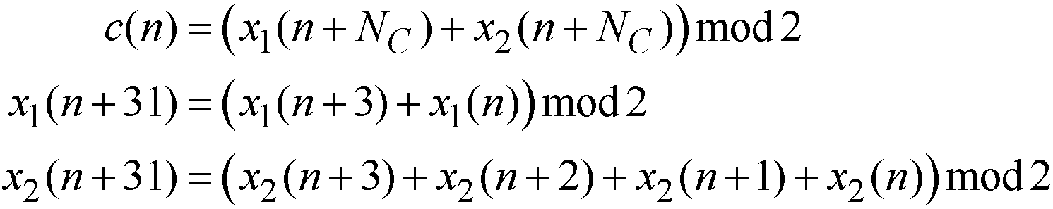
N = 1600 and C in equation (2), a 1 m- sequence x 1 (i) are x 1 (0) = 1, x 1 (n) = 0, (n = 1,2, ..., 30) Lt; / RTI > Initialization of the second m-sequence x 2 (i) may be initialized to different values depending on the system parameter values used in the channel or signal to which the sequence is applied,
The pseudo-random sequence c (i) may be initialized by Equation (3) at the beginning of each OFDM symbol.
&Quot; (3) "
In Equation (3), N CP has a value of 1 in the normal CP and 0 in the extended CP. N ID CSI can have any one of integers from 0 to 503. N ID CSI may be a virtual cell ID (VCID) for CSI-RS when signaled from an upper layer. The N ID CSI may be equal to the physical cell ID (PCI) if there is no signaling from the upper layer.
In a subframe configured for transmission of a CSI-RS, a CSI-RS sequence rl , ns (m) is a complex-valued modulation symbol a k used as a reference symbol on an antenna port p according to Equation (4) , l (p) .
&Quot; (4) "
Referring to Equation (4 ) , a k, l (p) is a complex modulation symbol mapped to the k-th subcarrier and the l-th OFDM symbol of the p-th antenna port. a k, l (p) are mapped by being multiplied by the CSI-RS sequence r l, ns (m ') and the orthogonal sequence w l " .
Each parameter of Equation (4) can be defined by Equation (5).
&Quot; (5) "

Referring to Equation (5), the necessary conditions for (k ', l') and n s can be given by Tables 2 and 3 described later.
A plurality of CSI-RS configurations may be used in one cell. The CSI-RS configuration includes a non-zero transmission power CSI-RS configuration indicating a pattern in which a CSI-RS is transmitted to each cell (or a transmission point (TP) RS for muting the PDSCH region corresponding to the CSI-RS transmission of the uplink RS and the downlink RS. Zero or one CSI-RS configuration per CSI process, or zero or multiple CSI RS configurations for a terminal assuming zero power CSI-RS for a terminal assuming non-power CSI-RS.
Information on one or more non-optical power CSI-RS configurations (hereinafter referred to as CSI-RS configurations) may be transmitted to each terminal of the corresponding cell. The information on the CSI-RS configuration includes 2-bit information indicating the number of antenna ports (hereinafter referred to as CSI-RS antenna ports) for transmitting non-linear power CSI-RSs as 1, 2, 4, And 5-bit information indicating a configurable CSI-RS pattern for each number of CSI-RS antenna ports.
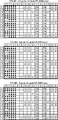
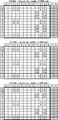
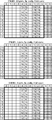
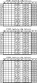
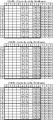
Table 2 shows the CSI-RS configuration in the general CP and the (k ', l'), i.e., the mapping of the CSI-RS pattern in
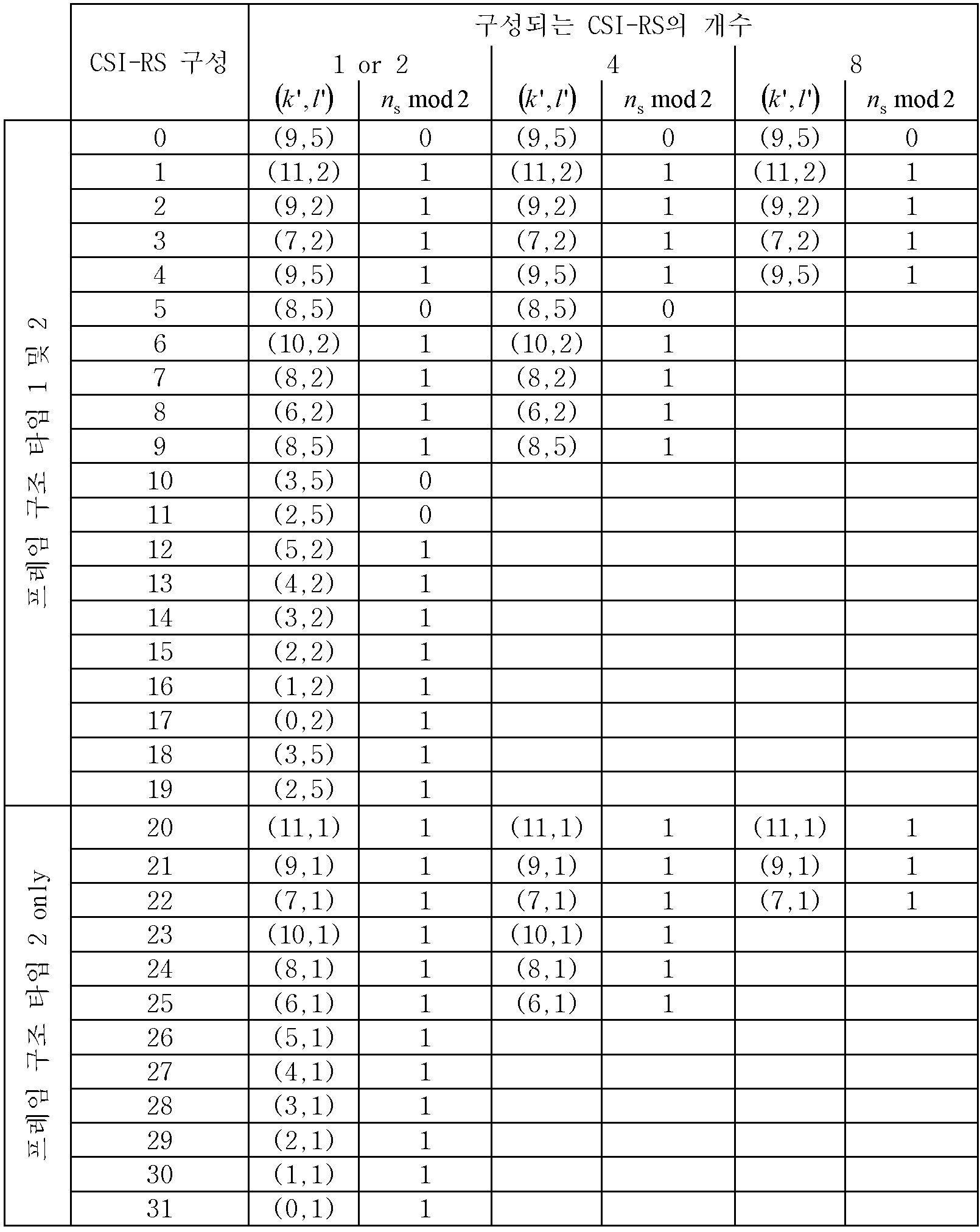

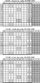
Referring to Table 2, a total of 32 CSI-RS configurations are provided when the number of antenna ports is one or two in the case of a general CP, and a total of 16 CSI-RS configurations are provided when the number of antenna ports is four. There are 8 CSI-RS configurations in total. Referring to Table 3, when the number of antenna ports is 1 or 2, a total of 28 types of CSI-RS are configured for the extended CP, 14 types of CSI-RS are configured when the number of antenna ports is 4, There are a total of seven CSI-RS configurations for eight.
Referring to Table 2 and Table 3, the location of a specific resource element to which the CSI-RS is mapped can be indicated for each CSI-RS antenna port number with respect to the CSI-RS configuration. That is, the location of the remaining resource elements to which the CSI-RS is mapped according to Equation (5) can be determined based on the location of the specific one resource element, and thus the entire CSI-RS You can see the pattern.
For example, if the number of CSI-RS antenna ports is 8 and the value of the CSI-RS configuration is 2 (= 00010), (k ', 1' And n s mod 2 = 1 are indicated. Therefore, it can be seen that within a subframe configured for CSI-RS transmission, the CSI-RS is mapped to a resource element with an OFDM symbol index of 2 and a subcarrier index of the second slot is 9. The resource element indicated by Table 2 may be one of the positions of the resource elements to which the CSI-RS to be transmitted through the first CSI-RS antenna port is mapped. The location of the remaining resource elements to which the CSI-RS is transmitted through the first CSI-RS antenna port and the location of the resource element to which the CSI-RS transmitted through the remaining CSI-RS antenna port are mapped, Lt; RTI ID = 0.0 > 2 < / RTI >
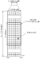
5 shows an example of a CSI-RS configuration and a CSI-RS pattern according to the number of CSI-RS antenna ports in a general CP.
FIG. 5- (a) shows the FDD + TDD, and FIG. 5 (b) shows the CSI-RS pattern in the case of TDD. In FIG. 5, the number indicated in each resource element indicates a CSI-RS configuration number. RS is an antenna port of a CSI-
The CSI-RS pattern of FIG. 5 can be applied to a case where the number of CRS antenna ports is 1, 4, or CRS is not transmitted. In addition, the CSI-RS pattern of FIG. 5 can be applied to a case where the control region is allocated to the first to fourth OFDM symbols in the subframe or the control region is not allocated. 5, the DMRS uses two code division multiplexing (CDM) groups (A: DMRS antenna ports {7,8, 11,13}, B: DMRS antenna ports {9,10,12,14}) However, the CSI-RS pattern of FIG. 5 can be applied to a case of using one CDM group.
6 shows an example of a CSI-RS configuration and a CSI-RS pattern according to the number of CSI-RS antenna ports in an extended CP.
As in FIG. 5, the numbers indicated in each resource element in FIG. 6 indicate the CSI-RS configuration number. RS is an antenna port of a CSI-
The CSI-RS pattern of FIG. 6 can be applied to a case where the number of CRS antenna ports is 1, 4, or CRS is not transmitted. In addition, the CSI-RS pattern of FIG. 6 can be applied to a case where the control area is allocated to the first to fourth OFDM symbols in the subframe, or the control area is not allocated.
Hereinafter, the matters related to the CRS, the control region, and the DMRS applied in FIG. 5 and FIG. 6 may be applied to the embodiments of the present invention described below.
The zero-power CSI-RS configuration is a 16-bit bitmap composed of four CSI-RS antenna ports. For a bit set to 1 in a 16-bit bitmap constituted by an upper layer, the UE transmits a resource element corresponding to four CSI-RS antenna ports in Table 2 and Table 3 to a zero power CSI-RS Can be set. More specifically, the most significant bit (MSB) of a 16-bit bitmap corresponds to the first CSI-RS configuration index in the case where the number of CSI-RS antenna ports is four in Tables 2 and 3. The following bits of the 16-bit bitmap correspond to the direction in which the CSI-RS configuration index increases in the case where the number of CSI-RS antenna ports is four in Tables 2 and 3. In the resource element set as the zero power CSI-RS, the PDSCH corresponding to the CSI-RS transmission of the adjacent cell or the TP is muted and the PDSCH can be transmitted in the resource element not set as the zero power CSI-RS.
The UE can transmit the CSI-RS only in the downlink slot satisfying the condition of n s mod 2 in Tables 2 and 3. In addition, the terminal may transmit a subframe or a paging message in which the transmission of the CSI RS conflicts with a synchronization signal, a physical broadcast channel (PBCH), a system information block type 1 (SystemInformationBlockType1), a special subframe of a TDD frame, The CSI-RS is not transmitted. In the set S with S = {15}, S = {15, 16}, S = {17, 18}, S = {19, 20} or S = {21, 22} A resource element used for transmission of a CSI-RS on a port is not used for transmission of a CSI-RS onto an antenna port in a PDSCH or another set S in the same slot.
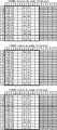
Table 4 shows an example of a subframe configuration in which the CSI-RS is transmitted.
I CSI-RS
T CSI-RS (subframe)
? CSI-RS (subframes)
Referring to Table 4, the period of the subframe to which the CSI-RS transmission (T CSI-RS) and an offset (Δ CSI-RS) can be determined according to the CSI-RS subframe structure (I CSI-RS). The CSI-RS subframe configuration can be configured separately for non-power CSI-RS and zero power CSI-RS. On the other hand, the subframe for transmitting CSI-RS needs to satisfy Equation (6).
&Quot; (6) "
For CSI-RS, the following parameters may be signaled from an upper layer such as radio resource control (RRC).
1) antennaPortsCount: has a length of 2 bits, and indicates the number of CSI-RS antenna ports in Table 2 or Table 3.
2) resouceConfig: has a length of 5 bits, and indicates CSI-RS configuration and its corresponding resource element, i.e., CSI-RS pattern, in Table 2 or Table 3.
3) subframeConfig: It has a length of 8 bits, and indicates the CSI-RS subframe structure in Table 4.
4) Pc: indicates the value related to the CSI-RS transmission power.
In addition, when a coordinated multi-point (CoMP) transmission environment is considered, N ID CSI of Equation (3) can be signaled from an upper layer.
The DMRS will be described.
DMRS is supported for transmission of PDSCH and can be transmitted on an antenna port p = 5, p = 7, p = 8 or p = 7,8, ...,
Figure 7 shows the mapping of DMRSs in a general CP.
In Fig. 7, Rx indicates transmission of the DMRS over the antenna port x. For example, R 7 represents transmitting the DMRS over
FIG. 7- (a) shows the mapping of the DMRS to the
That is,
The
As shown in Table 5, an OCC having a length of 4 can be applied over four OFDM symbols in one subframe on the time axis. For example, in a normal subframe using a normal CP, the four OFDM symbols to which the OCC is applied are the sixth, seventh, thirteenth, and fourteenth OFDM symbols as in the third subframe of FIG. 7 (a) (OFDM
An OCC of
8 shows the mapping of the DMRS in the extended CP.
In FIG. 8, Rx denotes transmission of the DMRS over the antenna port x. For example, R 7 represents transmitting the DMRS over
As described above, the CSI-RS is not transmitted in the special subframe of the TDD frame. However, when considering a new carrier type (NCT) or a small cell environment in the future, it may be necessary to transmit CSI-RS in a special subframe of a TDD frame. However, if the CSI-RS pattern used in the conventional general subframe is directly used in the special subframe, the number of CSI-RS patterns that can be configured due to the GP and UpPTS regions, which can not transmit the CSI-RS, have. That is, even when CSI-RS is transmitted in a special subframe in consideration of the NCT or the small cell environment, the number of CSI-RS patterns that can be practically applied when the CSI- Lt; / RTI >
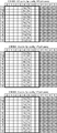
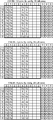
Table 6 shows the number of CSI-RS patterns that can be used in a normal subframe and a special subframe when the existing CSI-RS pattern is used intact.
CP
CP
Referring to Table 6, a normal subframe using a general CP can use 32, 16, and 8 CSI-RS patterns according to the number of antenna ports, while a normal CP is used and a special subframe configuration In the special subframe of 1, 2, 6, or 7, only 4, 2, and 1 CSI-RS patterns can be used depending on the number of antenna ports.
In the following description, the numbers indicated in each resource element indicate the CSI-RS configuration number. RS is an antenna port of a CSI-
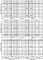
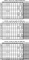
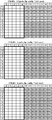
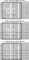
FIG. 9 shows a CSI-RS pattern when a CSI-RS pattern used in a normal subframe is directly used in a special subframe using a normal CP.
9 (a) and 9 (b) show a CSI-RS pattern in a special subframe in which the special subframe structure is four. Figs. 9- (c) and 9- (d) show a CSI-RS pattern in a special subframe in which the special subframe structure is 3 or 8. 9A to 9D, in a special subframe in which the special subframe structure is any one of 3, 4, or 8 and the general CP is used, the number of CSI-RS antenna ports is set to 1 RS patterns of six CSI-RS patterns when the number of CSI-RS antenna ports is four, six CSI-RS patterns when four CSI-RS antenna ports are used, and three CSI-RS patterns when eight CSI- Can be used.
FIG. 9- (e) shows a CSI-RS pattern in a special subframe in which the special subframe structure is 2 or 7. Fig. 9- (f) shows a CSI-RS pattern in a special subframe in which the special subframe structure is 1 or 6. Referring to Figs. 9- (e) and 9- (f), in a special subframe in which the special subframe structure is any one of 1, 2, 6, and 7 and uses a general CP, the number of CSI- RS pattern for four CSI-RS antenna ports, one CSI-RS pattern for eight CSI-RS antenna ports, four CSI-RS patterns for one or two CSI- It can be seen that only patterns can be used.
Fig. 9- (g) shows a CSI-RS pattern in a special subframe in which the special subframe structure is 9. FIG. 9- (h) shows a CSI-RS pattern in a special subframe in which the special subframe structure is 0 or 5. Referring to Figs. 9- (g) and 9- (h), there is no CSI-RS pattern that can be used in a special subframe in which the special subframe structure is 0, 5, or 9 and a general CP is used .
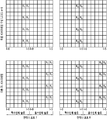
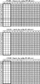
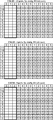
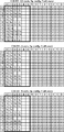
FIG. 10 shows a CSI-RS pattern when a CSI-RS pattern used in a normal subframe is directly used in a special subframe using an extended CP.
Fig. 10- (a) shows a CSI-RS pattern in a special subframe in which the special subframe structure is three. Fig. 10- (b) shows a CSI-RS pattern in a special subframe in which the special subframe structure is 2 or 6. 10A and 10B, in the special subframe in which the special subframe structure is 2, 3 or 6 and the extended CP is used, the number of CSI-RS antenna ports is 1 20 CSI-RS patterns when the number of CSI-RS antenna ports is 4, 10 CSI-RS patterns when 10 CSI-RS antenna ports are 4, and 5 CSI-RS patterns when 8 CSI- Can be used.
Fig. 10- (c) shows a CSI-RS pattern in a special subframe in which the special subframe structure is 1 or 5. Referring to FIG. 10- (c), in a special subframe in which the special subframe structure is 1 or 5 and the extended CP is used, when the number of CSI-RS antenna ports is one or two, eight CSI-RS patterns RS patterns are available when the number of CSI-RS antenna ports is four, and only two CSI-RS patterns are available when the number of CSI-RS antenna ports is eight.
Fig. 10- (d) shows a CSI-RS pattern in a special subframe in which the special subframe structure is seven. FIG. 10- (e) shows a CSI-RS pattern in a special subframe in which the special subframe structure is 0 or 4. Referring to Figs. 10- (d) and 10- (e), there is no CSI-RS pattern that can be used in a special subframe in which the special subframe structure is 0, 4 or 7 and the extended CP is used .
In order to solve such a problem, a new CSI-RS pattern is required in a special subframe, not a CSI-RS pattern used in a general subframe. That is, the position of the OFDM symbol to which the CSI-RS is mapped in the special subframe must be changed.
Hereinafter, a reference signal mapping method and / or a reference signal transmission method according to an embodiment of the present invention will be described with reference to embodiments. Various CSI-RS patterns may be constructed according to various embodiments of the present invention.
First, in order to construct a CSI-RS pattern for a special subframe, a CSI-RS pattern used in an existing general subframe can be divided into four parts for convenience.
1) The first part is a CSI-RS pattern part mapped to the first OFDM symbol and the second OFDM symbol to which the DMRS is mapped in the subframe. That is, referring to FIG. 5- (a), CSI-
2) The second part is the CSI-RS pattern part mapped to the third OFDM symbol and the fourth OFDM symbol to which the DMRS is mapped in the subframe. That is, referring to FIG. 5- (a), CSI-
3) The third part is a CSI-RS pattern part that is mapped to two consecutive OFDM symbols among the OFDM symbols to which the DMRS is not mapped in the subframe. Referring to FIG. 5A, CSI-
4) The fourth part is a CSI-RS pattern part mapped to two consecutive OFDM symbols among OFDM symbols to which the DMRS is not mapped in the subframe. That is, referring to FIG. 5B, the CSI-RS configurations 20 to 31 of the OFDM symbols of the OFDM
The first part and the second part of the CSI-RS pattern divided into four parts are mapped to the OFDM symbol to which the DMRS is mapped in the special subframe. That is, the first part is mapped to the first OFDM symbol and the second OFDM symbol to which the DMRS is mapped in the subframe, and the second part is mapped to the third OFDM symbol and the fourth OFDM symbol to which the DMRS is mapped in the subframe. However, as the position of the OFDM symbol to which the DMRS is mapped moves in the special subframe, the position to which the CSI-RS is mapped also moves. The third and fourth parts of the CSI-RS pattern are mapped to two OFDM symbols among the OFDM symbols to which the DMRS is not mapped even in the special subframe. That is, the third part is mapped to two consecutive OFDM symbols of the OFDM symbols to which the DMRS is not mapped in the subframe, and the fourth part is mapped to two non-consecutive OFDM symbols in which the DMRS is not mapped in the subframe .
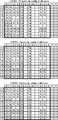
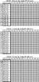
11 shows an example of a CSI-RS pattern configured according to a reference signal transmission method according to an embodiment of the present invention. Fig. 11- (a) shows a CSI-RS pattern of a special subframe using a general CP with a special subframe structure of 4. Fig. 11- (b) shows a CSI-RS pattern of a special subframe using a general CP with a special subframe structure of 3 or 8.
Referring to FIG. 11, a first part corresponding to CSI-
The third part corresponding to the CSI-
The fourth part corresponding to the CSI-RS configurations 20 to 31 is mapped to the OFDM symbols of the OFDM
Expressing the CSI-RS pattern of FIG. 11 in terms of a mathematical expression, a portion corresponding to 1 in Equation (5) can be changed to Equation (7).
&Quot; (7) "
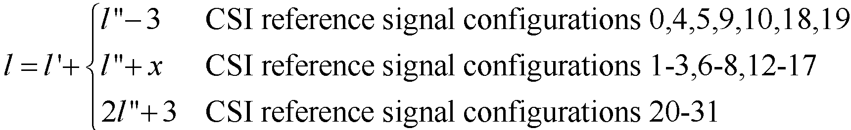
In Equation (7), x may be changed according to the position of the OFDM symbol to which the third part is mapped. For example, as shown in FIG. 11, when the third part is changed from the OFDM
12 shows another example of a CSI-RS pattern configured according to a reference signal transmission method according to an embodiment of the present invention. Fig. 12- (a) shows a CSI-RS pattern of a special subframe using a general CP with a special subframe structure of 2 or 7. Fig. 12- (b) shows a CSI-RS pattern of a special subframe using a general CP with a special subframe structure of 1 or 6.
Referring to FIG. 12, the first part corresponding to the CSI-
The third part corresponding to the CSI-
The fourth part corresponding to the CSI-RS configurations 20 to 31 is mapped to the OFDM symbols of the OFDM
Expressing the CSI-RS pattern of FIG. 12- (a) by Equation (8), a portion corresponding to l in Equation (5) can be changed to Equation (8).
&Quot; (8) "

Expressing the CSI-RS pattern of FIG. 12- (b) by the equation, the portion corresponding to 1 in Equation (5) can be changed to Equation (9).
&Quot; (9) "
In Equations (8) and (9), it can be reflected in Table 2 and / or Equations (8) and (9) that the second part is changed and mapped from the second slot to the first slot. Also, it can be reflected in Table 2 and / or
13 shows another example of a CSI-RS pattern configured according to a reference signal transmission method according to an embodiment of the present invention. FIG. 13 shows a CSI-RS pattern of a special subframe using a general CP with a special subframe structure of 9.
Referring to FIG. 13, a first part corresponding to CSI-
The third part corresponding to the CSI-
Referring to the CSI-RS pattern in FIG. 13, the portion corresponding to 1 in
&Quot; (10) "

In Equation (10), x may be changed according to the position of the OFDM symbol to which the third part is mapped. For example, as shown in FIG. 13, when the third part is changed from
FIG. 14 shows another example of a CSI-RS pattern configured according to a reference signal transmission method according to an embodiment of the present invention. Fig. 14 shows a CSI-RS pattern of a special subframe using a general CP and having a special subframe structure of 0 or 5.
Referring to FIG. 14, the first part corresponding to the CSI-
The third part corresponding to the CSI-
The CSI-RS pattern of FIG. 14- (a) can be expressed by Equation (11), and the portion corresponding to l in Equation (5) can be changed to Equation (11).
Equation (11)
In
The CSI-RS pattern of FIG. 14- (b) can be expressed by Equation (12), and the portion corresponding to l in Equation (5) can be changed to Equation (12).
&Quot; (12) "
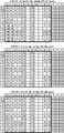
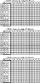
15 shows another example of a CSI-RS pattern configured according to a reference signal transmission method according to an embodiment of the present invention. 15 (a) and 15 (b) show a CSI-RS pattern of a special subframe using a special CP with a special subframe structure of 3. Figs. 15- (c) and Fig. 15- (d) show CSI-RS patterns of special subframes using the extended CP, with the special subframe structure being 2 or 6.
15, the first part corresponding to the CSI-
The third part corresponding to the CSI-
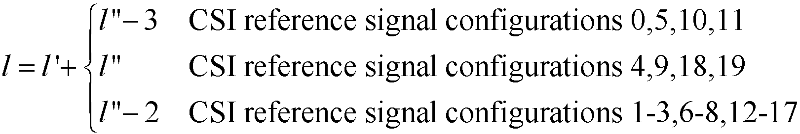
The CSI-RS pattern in FIGS. 15A and 15C can be expressed by Equation 13, and the portion corresponding to 1 in
&Quot; (13) "
The CSI-RS pattern of FIG. 15- (b) and FIG. 15- (d) can be expressed by Equation (14).
&Quot; (14) "

In Equation 14, it can be reflected in Table 2 and / or Equation 14 that the third part is changed from the second slot to the first slot and mapped.
16 shows another example of a CSI-RS pattern configured according to a reference signal transmission method according to an embodiment of the present invention. FIG. 16 shows a CSI-RS pattern of a special subframe using a special CP of 1 or 5 and a special subframe structure.
16, the first part corresponding to the CSI-
The third part corresponding to the CSI-
Referring to the CSI-RS pattern in FIG. 16, the portion corresponding to 1 in Equation (5) can be changed to Equation (15).
&Quot; (15) "

In Equation (15), x may be changed according to the position of the OFDM symbol to which the third part is mapped. For example, when a third part is mapped to an OFDM symbol of OFDM
17 shows another example of a CSI-RS pattern configured according to a reference signal transmission method according to an embodiment of the present invention. FIG. 17 shows a CSI-RS pattern of a special subframe using the extended CP, with a special subframe structure of 7.
17, the first part corresponding to the CSI-
The third part corresponding to the CSI-
If the CSI-RS pattern of FIG. 17- (a) is expressed by the equation, the part corresponding to 1 in equation (5) can be changed as shown in equation (16).
&Quot; (16) "
If the CSI-RS pattern of FIG. 17- (b) is expressed by the equation, the part corresponding to 1 in equation (5) can be changed as shown in equation (17).
&Quot; (17) "

In Equation (16) and Equation (17), x may be changed according to the position of the OFDM symbol to which the third part is mapped. For example, as shown in FIG. 17- (a), the third part is changed from the OFDM symbol of the OFDM
18 shows another example of a CSI-RS pattern configured according to a reference signal transmission method according to an embodiment of the present invention. Fig. 18 shows a CSI-RS pattern of a special subframe in which the special subframe structure is 0 or 4 and the extended CP is used.
Referring to FIG. 18, the first part corresponding to CSI-
The third part corresponding to the CSI-
The CSI-RS pattern in FIG. 18- (a) can be expressed by Equation (18), and the portion corresponding to 1 in Equation (5) can be changed to Equation (18).
&Quot; (18) "
In
The CSI-RS pattern in FIG. 18- (b) can be expressed by Equation (19), and the portion corresponding to 1 in Equation (5) can be changed to Equation (19).
&Quot; (19) "
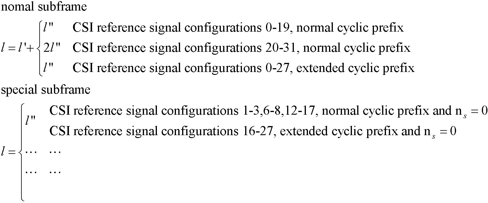
In the above embodiment, the CSI-RS pattern for the special subframe is replaced with the subframe structure corresponding to l in Equation (5) and the Equation (7) to Equation (19) according to the CP, 5 to 1 (corresponding to a normal sub-frame) and Equations (7) to (19) (corresponding to each special sub-frame of a special sub-frame) It is possible. For example, in the above-mentioned third part (CSI-
&Quot; (20) "
In addition, the resource elements and slot numbers to which the CSI-RS is mapped can be changed for each CSI-RS configuration in Tables 2 and 3, which are not mathematical expressions. That is, Table 2 can be changed for a special sub-frame using a general CP and Table 3 for a special sub-frame using an extended CP according to a special sub-frame configuration.
19 shows an embodiment of a reference signal transmission method according to an embodiment of the present invention.
Referring to FIG. 19, in step S100, the base station generates a CSI-RS sequence. The reference signal sequence may be generated by Equations (1) to (3).
In step S110, the base station maps the generated CSI-RS sequence using the modulation symbol to the resource element. The modulation symbol may be generated by Equation (4). The CSI-RS sequence may be mapped to a resource element according to the CSI-RS pattern described in Figures 11 to 18 according to various embodiments of the present invention. Either of
In step S120, the base station transmits the OFDM signal generated based on the CSI-RS sequence mapped to the resource element to the UE.
In step S130, the terminal receives the OFDM signal, demodulates it, and performs channel estimation. The procedure for demodulating the OFDM signal may be the reverse of the procedure for generating the OFDM signal. For example, the UE de-maps the received OFDM signal to the resource element to detect the modulation symbol and detects the CSI-RS sequence from the modulation symbol. The UE performs channel estimation by comparing the detected reference signal sequence with the CSI-RS sequence generated by the UE itself.
20 is a block diagram of a wireless communication system in which an embodiment of the present invention is implemented.
The
The reference signal generator 811 is configured to generate a CSI-RS sequence. The reference signal sequence may be generated by Equations (1) to (3).
The resource mapper 812 is configured to map the CSI-RS sequence generated using the modulation symbols to the resource element. The modulation symbol may be generated by Equation (4). The CSI-RS sequence may be mapped to a resource element according to the CSI-RS pattern described in Figures 11 to 18 according to various embodiments of the present invention. Either of
The transmitting unit 820 is configured to transmit the OFDM signal generated based on the CSI-RS sequence mapped to the resource element to the terminal 900.
The receiving unit 830 is configured to receive the uplink signal from the terminal 900.
The terminal 900 includes a
Receiver 930 is configured to receive an OFDM signal from
The
The transmitting unit 920 is configured to transmit the uplink signal to the
The foregoing description is merely illustrative of the technical idea of the present invention, and various changes and modifications may be made by those skilled in the art without departing from the essential characteristics of the present invention. Therefore, the embodiments disclosed in the present invention are intended to illustrate rather than limit the scope of the present invention, and the scope of the technical idea of the present invention is not limited by these embodiments. The scope of protection of the present invention should be construed according to the following claims, and all technical ideas within the scope of equivalents should be construed as falling within the scope of the present invention.
Claims (15)
Comprising: generating a channel state information (CSI) reference signal sequence;
Mapping the generated CSI-RS sequence to at least one resource element of a special subframe in a time division duplex (TDD) frame according to a CSI-RS pattern using a modulation symbol; And
And transmitting an orthogonal frequency division multiplexing (OFDM) signal generated based on the mapped CSI-RS sequence to a terminal,
Wherein the CSI-RS pattern is determined according to a configuration and a cyclic prefix (CP) of the special subframe.
Wherein the CSI-RS pattern includes a first OFDM symbol to which a demodulation reference signal (DMRS) is mapped and a first part to be configured to a second OFDM symbol.
Wherein if the special subframe uses a normal CP, the first part corresponds to CSI RS configurations 0, 5, 10 and 11.
Wherein the first part corresponds to CSI RS configurations 0, 1, 4, 5, 8 to 11 when the special subframe uses an extended CP.
Wherein the CSI-RS pattern comprises a third OFDM symbol to which a DMRS is mapped and a second part to be configured to a fourth OFDM symbol.
If the special subframe uses a generic CP, the second part corresponds to CSI RS configurations 4, 9, 18 and 19.
If the special subframe uses an extended CP, the second part corresponds to CSI RS configurations 2, 3, 6, 7, 12-15.
Wherein the CSI-RS pattern comprises a third part comprised of two consecutive OFDM symbols among the OFDM symbols to which the DMRS is not mapped.
If the special subframe uses a generic CP, the third part corresponds to CSI RS configurations 1, 2, 3, 6, 7, 8, 12 to 17.
If the special subframe uses the extended CP, the third part corresponds to the CSI RS configurations 16-27.
Wherein the CSI-RS pattern comprises a fourth part comprised of two consecutive OFDM symbols among OFDM symbols to which the DMRS is not mapped.
If the special subframe uses a generic CP, the fourth part corresponds to the CSI RS configurations 20 to 31. < RTI ID = 0.0 > 31. < / RTI >
A reference signal generator configured to generate a channel state information (CSI) reference signal sequence;
A resource configured to map the generated CSI-RS sequence to at least one resource element of a special subframe in a time division duplex (TDD) frame according to a CSI-RS pattern using a modulation symbol; Mapper; And
And a transmitter configured to transmit an orthogonal frequency division multiplexing (OFDM) signal generated based on the mapped CSI-RS sequence to a terminal,
Wherein the CSI-RS pattern is determined according to a configuration of a special subframe and a cyclic prefix (CP).
Receiving an orthogonal frequency division multiplexing (OFDM) signal generated based on a channel state information (CSI) reference signal (RS) sequence; And
And performing channel estimation by demodulating the received OFDM signal,
The CSI-RS sequence is mapped to at least one resource element of a special subframe in a time division duplex (TDD) frame according to a CSI-RS pattern using a modulation symbol,
Wherein the CSI-RS pattern is determined according to a configuration and a cyclic prefix (CP) of the special subframe.
A receiver configured to receive an orthogonal frequency division multiplexing (OFDM) signal generated based on a channel state information (CSI) reference signal (RS) sequence; And
And a channel estimator configured to demodulate the received OFDM signal to perform channel estimation,
The CSI-RS sequence is mapped to at least one resource element of a special subframe in a time division duplex (TDD) frame according to a CSI-RS pattern using a modulation symbol,
Wherein the CSI-RS pattern is determined according to a configuration of a special subframe and a cyclic prefix (CP).
Priority Applications (2)
| Application Number | Priority Date | Filing Date | Title |
|---|---|---|---|
| KR1020130053460A KR20140133367A (en) | 2013-05-10 | 2013-05-10 | Method and apparatus for transmitting reference signal in wireless communication system |
| PCT/KR2014/004188 WO2014182133A1 (en) | 2013-05-10 | 2014-05-09 | Method for transmitting reference signal in wireless communications system and apparatus therefor |
Applications Claiming Priority (1)
| Application Number | Priority Date | Filing Date | Title |
|---|---|---|---|
| KR1020130053460A KR20140133367A (en) | 2013-05-10 | 2013-05-10 | Method and apparatus for transmitting reference signal in wireless communication system |
Publications (1)
| Publication Number | Publication Date |
|---|---|
| KR20140133367A true KR20140133367A (en) | 2014-11-19 |
Family
ID=51867526
Family Applications (1)
| Application Number | Title | Priority Date | Filing Date |
|---|---|---|---|
| KR1020130053460A KR20140133367A (en) | 2013-05-10 | 2013-05-10 | Method and apparatus for transmitting reference signal in wireless communication system |
Country Status (2)
| Country | Link |
|---|---|
| KR (1) | KR20140133367A (en) |
| WO (1) | WO2014182133A1 (en) |
Families Citing this family (4)
| Publication number | Priority date | Publication date | Assignee | Title |
|---|---|---|---|---|
| KR102327739B1 (en) * | 2015-01-29 | 2021-11-17 | 파나소닉 인텔렉츄얼 프로퍼티 코포레이션 오브 아메리카 | Communication method and communication device |
| CN111478761B (en) * | 2015-04-10 | 2022-10-18 | 阿里斯卡尔股份有限公司 | Method and apparatus for transmitting and receiving channel state information-reference signal |
| US10505685B2 (en) * | 2016-08-26 | 2019-12-10 | Qualcomm Incorporated | Adapting to delay spread variation in wireless communication systems |
| CN112448908B (en) * | 2019-09-03 | 2022-12-13 | 维沃移动通信有限公司 | PTS sending method, receiving method, sending end equipment and receiving end equipment |
-
2013
- 2013-05-10 KR KR1020130053460A patent/KR20140133367A/en not_active Application Discontinuation
-
2014
- 2014-05-09 WO PCT/KR2014/004188 patent/WO2014182133A1/en active Application Filing
Also Published As
| Publication number | Publication date |
|---|---|
| WO2014182133A1 (en) | 2014-11-13 |
Similar Documents
| Publication | Publication Date | Title |
|---|---|---|
| JP6129374B2 (en) | Method and apparatus for providing setting information of channel state information reference signal in wireless communication system supporting multiple antennas | |
| CN106465173B (en) | Method and apparatus for performing measurement using Discovery Reference Signal (DRS) in wireless communication system | |
| KR101740221B1 (en) | Method and Apparatus for allocating Channel State Information-Reference Signal in wireless communication system | |
| US9344245B2 (en) | Apparatus and method for allocating channel state information-reference signal in wireless communication system | |
| KR101757301B1 (en) | Apparatus for performing comp communication using a precoded sounding reference signal, and method for same | |
| KR20150018170A (en) | Method and apparatus for transmitting reference signal in wireless communication system | |
| KR101939295B1 (en) | Method for receiving downlink data channels in multicell-based wireless communication systems and apparatus for same | |
| KR101572397B1 (en) | Method and apparatus for transmitting uplink reference signal in wireless communication system | |
| KR101253197B1 (en) | Method and base station for receiving reference signal, and method and user equipment for receiving reference signal | |
| EP2763339B1 (en) | Method and apparatus for setting plurality of reference signal configurations in wireless communication system | |
| WO2016108483A1 (en) | Method for performing channel estimation in wireless communication system and apparatus therefor | |
| US9048976B2 (en) | Apparatus and method for transmitting reference signals in wireless communication system | |
| US9055476B2 (en) | Method and apparatus for measuring interference in a wireless communication system | |
| US8699618B2 (en) | Method for generating plurality of DM-RS sequences, communication terminal device using same, and base station using same | |
| US9369898B2 (en) | Method and device for measuring interference in a wireless communication system | |
| KR102094419B1 (en) | Method and apparatus for transmitting reference signal in wireless communication system | |
| KR20140133367A (en) | Method and apparatus for transmitting reference signal in wireless communication system | |
| KR101615242B1 (en) | Method for measuring interference of neighboring base station in wireless communication system and method for supporting interference measurement | |
| US9154209B2 (en) | Method and apparatus for transmitting feedback in a wireless communication system | |
| KR101740431B1 (en) | Method for transmitting downlink reference signal and appratus for the same | |
| KR20150090425A (en) | Apparatus and method for mapping uplink demodulation-reference signal sequence | |
| KR20150090586A (en) | Apparatus and method for mapping uplink demodulation-reference signal sequence | |
| KR102180254B1 (en) | Apparatus and method for configuring reference signal in wireless communication system supporting small cells | |
| KR20140121244A (en) | Method and apparatus of transmitting reference signal in small cell environment | |
| KR102136812B1 (en) | Apparatus and method for configuring reference signal in wireless communication system supporting small cells |
Legal Events
| Date | Code | Title | Description |
|---|---|---|---|
| N231 | Notification of change of applicant | ||
| WITN | Withdrawal due to no request for examination |