KR101757301B1 - Apparatus for performing comp communication using a precoded sounding reference signal, and method for same - Google Patents
Apparatus for performing comp communication using a precoded sounding reference signal, and method for same Download PDFInfo
- Publication number
- KR101757301B1 KR101757301B1 KR1020127019019A KR20127019019A KR101757301B1 KR 101757301 B1 KR101757301 B1 KR 101757301B1 KR 1020127019019 A KR1020127019019 A KR 1020127019019A KR 20127019019 A KR20127019019 A KR 20127019019A KR 101757301 B1 KR101757301 B1 KR 101757301B1
- Authority
- KR
- South Korea
- Prior art keywords
- matrix
- base station
- srs
- comp
- terminal
- Prior art date
Links
- 238000000034 method Methods 0.000 title claims abstract description 58
- 238000004891 communication Methods 0.000 title claims abstract description 40
- 239000011159 matrix material Substances 0.000 claims abstract description 161
- 241001463014 Chazara briseis Species 0.000 claims abstract 2
- 230000005540 biological transmission Effects 0.000 description 104
- 238000010586 diagram Methods 0.000 description 34
- 238000010295 mobile communication Methods 0.000 description 22
- 238000012545 processing Methods 0.000 description 9
- 125000004122 cyclic group Chemical group 0.000 description 6
- 230000015654 memory Effects 0.000 description 6
- 230000008569 process Effects 0.000 description 6
- 238000013468 resource allocation Methods 0.000 description 6
- 238000005516 engineering process Methods 0.000 description 5
- 238000013507 mapping Methods 0.000 description 5
- 230000006870 function Effects 0.000 description 3
- 238000005259 measurement Methods 0.000 description 3
- 238000001774 stimulated Raman spectroscopy Methods 0.000 description 3
- 101000741965 Homo sapiens Inactive tyrosine-protein kinase PRAG1 Proteins 0.000 description 2
- 102100038659 Inactive tyrosine-protein kinase PRAG1 Human genes 0.000 description 2
- 230000002776 aggregation Effects 0.000 description 2
- 238000004220 aggregation Methods 0.000 description 2
- 230000000694 effects Effects 0.000 description 2
- 230000007774 longterm Effects 0.000 description 2
- 230000009467 reduction Effects 0.000 description 2
- 230000004044 response Effects 0.000 description 2
- 230000011664 signaling Effects 0.000 description 2
- 241000760358 Enodes Species 0.000 description 1
- 230000004913 activation Effects 0.000 description 1
- 239000000654 additive Substances 0.000 description 1
- 230000000996 additive effect Effects 0.000 description 1
- 238000003491 array Methods 0.000 description 1
- 230000008901 benefit Effects 0.000 description 1
- 239000000969 carrier Substances 0.000 description 1
- 230000000295 complement effect Effects 0.000 description 1
- 238000000794 confocal Raman spectroscopy Methods 0.000 description 1
- 238000011500 cytoreductive surgery Methods 0.000 description 1
- 230000000116 mitigating effect Effects 0.000 description 1
- 230000001151 other effect Effects 0.000 description 1
- 238000005070 sampling Methods 0.000 description 1
- 230000008054 signal transmission Effects 0.000 description 1
- 238000012546 transfer Methods 0.000 description 1
Images


Classifications
-
- H—ELECTRICITY
- H04—ELECTRIC COMMUNICATION TECHNIQUE
- H04B—TRANSMISSION
- H04B7/00—Radio transmission systems, i.e. using radiation field
- H04B7/02—Diversity systems; Multi-antenna system, i.e. transmission or reception using multiple antennas
- H04B7/022—Site diversity; Macro-diversity
- H04B7/024—Co-operative use of antennas of several sites, e.g. in co-ordinated multipoint or co-operative multiple-input multiple-output [MIMO] systems
-
- H—ELECTRICITY
- H04—ELECTRIC COMMUNICATION TECHNIQUE
- H04B—TRANSMISSION
- H04B7/00—Radio transmission systems, i.e. using radiation field
- H04B7/02—Diversity systems; Multi-antenna system, i.e. transmission or reception using multiple antennas
- H04B7/04—Diversity systems; Multi-antenna system, i.e. transmission or reception using multiple antennas using two or more spaced independent antennas
- H04B7/06—Diversity systems; Multi-antenna system, i.e. transmission or reception using multiple antennas using two or more spaced independent antennas at the transmitting station
- H04B7/0613—Diversity systems; Multi-antenna system, i.e. transmission or reception using multiple antennas using two or more spaced independent antennas at the transmitting station using simultaneous transmission
- H04B7/0615—Diversity systems; Multi-antenna system, i.e. transmission or reception using multiple antennas using two or more spaced independent antennas at the transmitting station using simultaneous transmission of weighted versions of same signal
- H04B7/0617—Diversity systems; Multi-antenna system, i.e. transmission or reception using multiple antennas using two or more spaced independent antennas at the transmitting station using simultaneous transmission of weighted versions of same signal for beam forming
-
- H—ELECTRICITY
- H04—ELECTRIC COMMUNICATION TECHNIQUE
- H04J—MULTIPLEX COMMUNICATION
- H04J11/00—Orthogonal multiplex systems, e.g. using WALSH codes
- H04J11/0023—Interference mitigation or co-ordination
- H04J11/005—Interference mitigation or co-ordination of intercell interference
- H04J11/0053—Interference mitigation or co-ordination of intercell interference using co-ordinated multipoint transmission/reception
-
- H—ELECTRICITY
- H04—ELECTRIC COMMUNICATION TECHNIQUE
- H04L—TRANSMISSION OF DIGITAL INFORMATION, e.g. TELEGRAPHIC COMMUNICATION
- H04L25/00—Baseband systems
- H04L25/02—Details ; arrangements for supplying electrical power along data transmission lines
- H04L25/03—Shaping networks in transmitter or receiver, e.g. adaptive shaping networks
- H04L25/03006—Arrangements for removing intersymbol interference
- H04L25/03343—Arrangements at the transmitter end
-
- H—ELECTRICITY
- H04—ELECTRIC COMMUNICATION TECHNIQUE
- H04L—TRANSMISSION OF DIGITAL INFORMATION, e.g. TELEGRAPHIC COMMUNICATION
- H04L5/00—Arrangements affording multiple use of the transmission path
- H04L5/003—Arrangements for allocating sub-channels of the transmission path
- H04L5/0032—Distributed allocation, i.e. involving a plurality of allocating devices, each making partial allocation
- H04L5/0035—Resource allocation in a cooperative multipoint environment
-
- H—ELECTRICITY
- H04—ELECTRIC COMMUNICATION TECHNIQUE
- H04W—WIRELESS COMMUNICATION NETWORKS
- H04W88/00—Devices specially adapted for wireless communication networks, e.g. terminals, base stations or access point devices
- H04W88/02—Terminal devices
-
- H—ELECTRICITY
- H04—ELECTRIC COMMUNICATION TECHNIQUE
- H04W—WIRELESS COMMUNICATION NETWORKS
- H04W88/00—Devices specially adapted for wireless communication networks, e.g. terminals, base stations or access point devices
- H04W88/08—Access point devices
Landscapes
- Engineering & Computer Science (AREA)
- Signal Processing (AREA)
- Computer Networks & Wireless Communication (AREA)
- Power Engineering (AREA)
- Mobile Radio Communication Systems (AREA)
Abstract
프리코딩된 사운딩 참조신호를 이용하여 CoMP 통신을 수행하는 장치 및 그 방법 장치와 그 방법이 개시된다. 본 발명에 따른 프리코딩된 사운딩 참조신호를 이용하여 CoMP(Coordinated Multiple point) 통신을 수행하는 방법은, 기지국이 인접 셀의 단말로부터 제 1 행렬에 의해 프리코딩된 사운딩 참조신호(Sounding Reference Signal, SRS)를 수신하는 단계; 상기 수신한 SRS로부터의 상기 제 1 행렬의 허미션(hermitian) 행렬 및 상기 단말과 상기 기지국 간의 하향링크 채널 행렬을 이용하여 유효 인접 채널(effective neighboring channel) 행렬을 획득하는 단계; 및 상기 유효 인접 채널 행렬에 기초하여 상기 기지국으로부터 서빙받는 하나 이상의 단말에게 전송할 프리코딩 행렬을 결정하는 단계를 포함한다. 여기서, 상기 유효 인접 채널 행렬은 상기 단말이 상기 단말의 서빙 기지국으로부터 데이터 수신을 위해 수신 빔을 향해야하는 방향을 나타내는 행렬이다.An apparatus and method for performing CoMP communication using a precoded sounding reference signal and an apparatus and a method thereof are disclosed. A method for performing Coordinated Multiple Point (CoMP) communication using a precoded sounding reference signal according to the present invention is a method for performing Coordinated Multiple Point (CoMP) communication using a sounding reference signal , SRS); Obtaining an effective neighboring channel matrix using a hermit matrix of the first matrix from the received SRS and a downlink channel matrix between the terminal and the base station; And determining a precoding matrix to be transmitted to one or more terminals serviced by the base station based on the effective neighboring channel matrix. Here, the effective neighboring channel matrix is a matrix indicating a direction in which the mobile station should direct a receive beam for data reception from the serving base station of the mobile station.
Description
본 발명은 무선 통신 시스템에 관한 것으로, 보다 상세하게는 프리코딩된 사운딩 참조신호를 이용하여 CoMP 통신을 수행하는 장치 및 그 방법에 관한 것이다.The present invention relates to a wireless communication system, and more particularly, to an apparatus and method for performing CoMP communication using a precoded sounding reference signal.
협력 멀티 포인트(Coordinated Multi-Point, CoMP) 시스템은 다중 셀 환경에서 개선된 MIMO 전송을 적용함으로써 셀 경계에 있는 사용자의 처리량을 개선하기 위한 시스템이다. CoMP 시스템을 적용하면 다중 셀 환경에서 셀 간 간섭(Inter-Cell Interference)을 줄일 수 있다. 이러한 CoMP 시스템을 이용하면, 단말은 다중-셀 기지국(Multi-cell base-station)으로부터 공동으로 데이터를 지원받을 수 있다.A Coordinated Multi-Point (CoMP) system is a system for improving the throughput of a user at a cell boundary by applying improved MIMO transmission in a multi-cell environment. The CoMP system can reduce inter-cell interference in a multi-cell environment. With the CoMP system, a UE can receive data jointly from a multi-cell base station.
또한, 각 기지국은 동일한 무선 주파수 자원(Same Radio Frequency Resource)을 이용하여 하나 이상의 단말(UE 1, UE 2, ... UE K)에 동시에 지원함으로써 시스템의 성능을 향상시킬 수 있다. 또한, 기지국은 기지국과 단말 간의 채널상태정보(CSI)에 기초하여 공간 분할 다중접속(Space Division Multiple Access: SDMA) 방법을 수행할 수 있다.Also, each base station can simultaneously support one or more UEs (UE 1, UE 2, ..., UE K) using the same radio frequency resource (Same Radio Frequency Resource) to improve the performance of the system. In addition, the BS may perform a Space Division Multiple Access (SDMA) method based on channel state information (CSI) between the BS and the MS.
이러한 CoMP 방식은 데이터 공유를 통한 협력적 MIMO (Co-MIMO) 형태의 조인트 프로세싱(JP: Joint Processing)과 협력 스케줄링 방식/빔포밍 방식(CS/CB: Coordinated Scheduling scheme/Beamforming scheme)으로 나눌 수 있다.The CoMP scheme can be divided into cooperative MIMO (Co-MIMO) joint processing (Joint Processing) and cooperative scheduling scheme / beamforming scheme (CS / CB) through data sharing .
이와 같이, 차세대 통신 시스템인 3GPP LTE-A에서는 CoMP 시스템을 도입하기로 예정하고 있으나, 아직까지 다중 셀 간의 셀 간 간섭 협력을 위한 구체적인 방법을 제시하지 못하고 있다.As described above, the 3GPP LTE-A, a next generation communication system, intends to introduce a CoMP system, but a specific method for intercell interference cooperation between multiple cells has not been proposed yet.
본 발명에서 이루고자 하는 기술적 과제는 프리코딩된 사운딩 참조신호를 이용하여 CoMP(Coordinated Multiple point) 통신을 수행하는 방법을 제공하는 데 있다.SUMMARY OF THE INVENTION The present invention provides a method of performing Coordinated Multiple Point (CoMP) communication using a precoded sounding reference signal.
본 발명에서 이루고자 하는 다른 기술적 과제는 프리코딩된 사운딩 참조신호를 이용하여 CoMP(Coordinated Multiple point) 통신을 수행하는 장치를 제공하는 데 있다.According to another aspect of the present invention, there is provided an apparatus for performing Coordinated Multiple Point (CoMP) communication using a precoded sounding reference signal.
본 발명에서 이루고자 하는 기술적 과제들은 상기 기술적 과제로 제한되지 않으며, 언급하지 않은 또 다른 기술적 과제들은 아래의 기재로부터 본 발명이 속하는 기술분야에서 통상의 지식을 가진 자에게 명확하게 이해될 수 있을 것이다.The technical problems to be solved by the present invention are not limited to the technical problems and other technical problems which are not mentioned can be understood by those skilled in the art from the following description.
상기의 기술적 과제를 달성하기 위한, 본 발명에 따른 프리코딩된 사운딩 참조신호를 이용하여 CoMP(Coordinated Multiple point) 통신을 수행하는 방법은, 기지국이 인접 셀의 단말로부터 제 1 행렬(![]()
![]()
![]()
![]()
상기 방법은, 상기 수신한 SRS부터 상기 단말의 CoMP 스케줄링 정보를 획득하는 단계를 더 포함하며, 상기 프리코딩 행렬 결정 단계는 상기 단말에 스케줄링된 시간 또는 주파수 자원과 중복되는 상기 기지국으로부터 서빙받는 하나 이상의 단말에게 전송할 프리코딩 행렬을 결정할 수 있다.The method may further include acquiring CoMP scheduling information of the UE from the received SRS, wherein the precoding matrix determining step includes determining a precoding matrix of the at least one The precoding matrix to be transmitted to the UE can be determined.
상기 결정된 프리코딩 행렬은 상기 유효 인접 채널 행렬의 널 공간(null space) 내에 존재하는 행렬로 결정될 수 있다.The determined precoding matrix may be determined as a matrix existing in a null space of the effective adjacent channel matrix.
상기 제 1 행렬(![]()
![]()
![]()
![]()
![]()
![]()
![]()
![]()
상기 SRS는 사전에 예약된 시간 또는 주파수 자원을 통해 전송될 수 있다.The SRS may be transmitted over a previously reserved time or frequency resource.
상기의 기술적 과제를 달성하기 위한, 본 발명에 따른 프리코딩된 사운딩 참조신호를 이용하여 CoMP(Coordinated Multiple point) 통신을 수행하는 방법은, 단말이 프리코딩되지 않은 사운딩 참조신호(Sounding Reference Signal, SRS)를 서빙 기지국으로 전송하는 단계; 상기 서빙 기지국이 상기 단말로 데이터 전송을 위해 사용하는 프리코딩 행렬을 상기 서빙 기지국으로부터 수신하는 단계; 및 상기 수신한 프리코딩 행렬에 기초하여 수신 행렬을 결정하고, 결정된 수신 행렬의 허미션 행렬을 SRS에 프리코딩하여 인접 기지국으로 전송하는 단계를 포함할 수 있다.According to another aspect of the present invention, there is provided a method of performing Coordinated Multiple Point (CoMP) communication using a precoded sounding reference signal according to the present invention, , SRS) to the serving base station; Receiving from the serving BS a precoding matrix used by the serving BS for data transmission to the MS; And a step of determining a reception matrix based on the received precoding matrix, precoding the hermion matrix of the determined reception matrix to an SRS, and transmitting the precoding matrix to an adjacent base station.
상기 방법은, 상기 서빙 기지국으로부터 상기 단말의 SRS 구성 정보를 수신하는 단계를 더 포함하되, 상기 SRS 전송 단계에서, 상기 단말은 상기 수신한 SRS 구성 정보에 기초하여 상기 SRS를 전송한다.The method may further include receiving SRS configuration information of the MS from the serving BS, wherein the MS transmits the SRS based on the received SRS configuration information.
상기 서빙 기지국에 의해 결정된 프리코딩 행렬은 상기 서빙 기지국이 상기 단말로부터 수신한 사운딩 참조신호를 이용하여 상기 단말과 상기 기지국 간의 하향링크 채널 추정에 기초하여 결정된 것일 수 있다.The precoding matrix determined by the serving base station may be determined based on downlink channel estimation between the mobile station and the base station using the sounding reference signal received from the mobile station.
상기의 다른 기술적 과제를 해결하기 위한, 프리코딩된 사운딩 참조신호를 이용하여 CoMP(Coordinated Multiple point) 통신을 수행하는 기지국 장치는, 인접 셀의 단말로부터 제 1 행렬(![]()
![]()
![]()
![]()
상기 프로세서는 상기 수신한 SRS부터 상기 단말의 CoMP 스케줄링 정보를 더 획득하며, 상기 획득한 스케줄링 정보에 기초하여 상기 단말에 스케줄링된 시간 또는 주파수 자원과 중복되는 상기 기지국으로부터 서빙받는 하나 이상의 단말에게 전송할 프리코딩 행렬을 결정할 수 있다.Wherein the processor further acquires CoMP scheduling information of the UE from the received SRS and transmits the CoMP scheduling information to the UE in response to the scheduling information, The coding matrix can be determined.
상기 프로세서에 의해 결정된 상기 프리코딩 행렬은 상기 유효 인접 채널 행렬의 널 공간(null space) 내에 존재하는 행렬일 수 있다.The precoding matrix determined by the processor may be a matrix existing in a null space of the effective adjacent channel matrix.
상기의 다른 기술적 과제를 해결하기 위한, 프리코딩된 사운딩 참조신호를 이용하여 CoMP(Coordinated Multiple point) 통신을 수행하는 단말 장치는, 프리코딩되지 않은 사운딩 참조신호(Sounding Reference Signal, SRS)를 서빙 기지국으로 전송하는 송신기; 상기 서빙 기지국이 상기 단말로 데이터 전송을 위해 사용하는 프리코딩 행렬을 상기 서빙 기지국으로부터 수신하는 수신기; 상기 수신한 프리코딩 행렬에 기초하여 수신 행렬을 결정하고, 결정된 수신 행렬의 허미션 행렬을 SRS에 프리코딩하는 프로세서; 및 상기 프리코딩된 SRS를 인접 기지국으로 전송하는 송신기를 포함할 수 있다.According to another aspect of the present invention, there is provided a terminal apparatus for performing Coordinated Multiple Point (CoMP) communication using a precoded sounding reference signal, comprising: a sounding reference signal (SRS) A transmitter for transmitting to the serving base station; A receiver for receiving from the serving base station a precoding matrix used by the serving base station for data transmission to the mobile station; A processor for determining a received matrix based on the received precoding matrix and precoding the hermetion matrix of the determined received matrix to an SRS; And a transmitter for transmitting the precoded SRS to an adjacent base station.
상기 단말 장치는, 상기 서빙 기지국으로부터 상기 단말의 SRS 구성 정보를 수신하는 수신기를 더 포함하되, 상기 SRS를 전송하는 송신기는, 상기 수신한 SRS 구성 정보에 기초하여 상기 SRS를 전송한다.The terminal apparatus further includes a receiver for receiving the SRS configuration information of the terminal from the serving base station, and the transmitter for transmitting the SRS transmits the SRS based on the received SRS configuration information.
본 발명의 다양한 실시예에 의하면, 셀 경계에 위치한 단말에 미치는 셀 간 간섭을 제거, 완화함으로써 단말의 통신 성능을 현저히 향상시킬 수 있다.According to various embodiments of the present invention, communication performance of a terminal can be remarkably improved by eliminating and mitigating inter-cell interference on a terminal located at a cell boundary.
또한, 본 발명에 따르면 단말의 SRS 신호 전송에 기초하여 셀 간 간섭을 제어함으로써, 백홀 링크를 통한 과도한 정보 공유로 인한 지연 발생으로 통신 성능 저하되는 문제점을 해결할 수 있다.In addition, according to the present invention, the inter-cell interference is controlled based on the SRS signal transmission from the terminal, thereby solving the problem that the communication performance is deteriorated due to the delay caused by excessive information sharing through the backhaul link.
본 발명에서 얻은 수 있는 효과는 이상에서 언급한 효과들로 제한되지 않으며, 언급하지 않은 또 다른 효과들은 아래의 기재로부터 본 발명이 속하는 기술분야에서 통상의 지식을 가진 자에게 명확하게 이해될 수 있을 것이다.The effects obtained by the present invention are not limited to the above-mentioned effects, and other effects not mentioned can be clearly understood by those skilled in the art from the following description will be.
본 발명에 관한 이해를 돕기 위해 상세한 설명의 일부로 포함되는, 첨부 도면은 본 발명에 대한 실시예를 제공하고, 상세한 설명과 함께 본 발명의 기술적 사상을 설명한다.
도 1은 본 발명에 따른 무선 통신 시스템(100)에서의 기지국(105) 및 단말(110)의 구성을 도시한 블록도,
도 2는 이동통신 시스템의 일 예인 3GPP LTE 시스템에서 사용되는 무선 프레임의 구조를 예시하는 도면,
도 3은 이동통신 시스템의 일 예인 3GPP LTE 시스템의 하향링크 및 상향링크 서브프레임의 구조를 나타낸 도면,
도 4는 본 발명에서 사용되는 하향링크의 시간-주파수 자원 격자 구조(resource grid structure)를 나타낸 도면,
도 5는 일반적인 다중 안테나(MIMO) 통신 시스템의 구성도,
도 6은 NT개의 송신 안테나에서 수신 안테나 i로의 채널을 도시한 도면,
도 7은 이동통신 시스템의 일 예인 3GPP LTE 시스템에서의 참조신호 패턴을 나타낸 도면,
도 8은 SRS 심볼을 포함하는 상향링크 서브프레임 구성의 일 예를 나타낸 도면,
도 9는 프리코딩되지 않은 전체 랭크 SRS 전송의 일 예를 나타낸 도면,
도 10은 프리코딩된 전체 랭크 SRS 전송의 일 예를 나타낸 도면,
도 11은 CoMP 협력 기지국의 협력 동작의 개념을 설명하기 위해 나타낸 도면,
도 12는 CoMP 협력 동작을 수행하는 단말과 기지국 간들 간의 하향링크 CoMP CS/CB 동작을 위한 절차의 일 예를 나타낸 도면,
도 13은 CoMP 협력 동작을 수행하는 단말과 기지국 간들 간의 하향링크 CoMP CS/CB 동작을 위한 절차의 일 예를 나타낸 도면,
도 14는 CoMP 협력 동작을 수행하는 단말과 기지국 간들 간의 상향링크 CoMP CS/CB 동작을 위한 절차의 일 예를 나타낸 도면,
도 15는 CoMP 협력 동작을 수행하는 단말과 기지국 간들 간의 하향링크 CoMP CS/CB 동작을 위한 절차의 다른 예를 나타낸 도면, 그리고,
도 16은 CoMP 협력 동작을 수행하는 단말과 기지국 간들 간의 상향링크 CoMP CS/CB 동작을 위한 절차의 다른 예를 나타낸 도면이다.BRIEF DESCRIPTION OF THE DRAWINGS The accompanying drawings, which are included to provide a further understanding of the invention and are incorporated in and constitute a part of the specification, illustrate embodiments of the invention and, together with the description, serve to explain the principles of the invention.
1 is a block diagram showing the configuration of a
2 is a diagram illustrating a structure of a radio frame used in a 3GPP LTE system, which is an example of a mobile communication system,
3 is a diagram illustrating a structure of a downlink and an uplink subframe in a 3GPP LTE system, which is an example of a mobile communication system;
4 is a diagram illustrating a downlink time-frequency resource grid structure used in the present invention.
5 is a block diagram of a general multi-antenna (MIMO) communication system,
6 is a diagram showing channels from N T transmit antennas to receive antenna i,
7 is a diagram illustrating a reference signal pattern in a 3GPP LTE system, which is an example of a mobile communication system;
8 is a diagram illustrating an example of a configuration of an uplink subframe including an SRS symbol,
9 is a diagram illustrating an example of full rank SRS transmission that is not precoded;
10 is a diagram illustrating an example of precoded full rank SRS transmission,
11 is a diagram for explaining the concept of cooperative operation of CoMP cooperation base stations,
12 is a diagram illustrating an example of a procedure for a downlink CoMP CS / CB operation between a UE and a base station performing CoMP cooperation operation;
13 is a diagram illustrating an example of a procedure for a downlink CoMP CS / CB operation between a UE and a base station performing CoMP cooperative operation;
FIG. 14 is a diagram illustrating an example of a procedure for an uplink CoMP CS / CB operation between a terminal and a base station performing CoMP cooperation operation; FIG.
15 is a diagram illustrating another example of a procedure for a downlink CoMP CS / CB operation between a terminal and a base station performing CoMP cooperation operation,
FIG. 16 is a diagram illustrating another example of procedures for uplink CoMP CS / CB operation between a UE and a base station performing CoMP cooperation operation.
이하, 본 발명에 따른 바람직한 실시 형태를 첨부된 도면을 참조하여 상세하게 설명한다. 첨부된 도면과 함께 이하에 개시될 상세한 설명은 본 발명의 예시적인 실시형태를 설명하고자 하는 것이며, 본 발명이 실시될 수 있는 유일한 실시형태를 나타내고자 하는 것이 아니다. 이하의 상세한 설명은 본 발명의 완전한 이해를 제공하기 위해서 구체적 세부사항을 포함한다. 그러나, 당업자는 본 발명이 이러한 구체적 세부사항 없이도 실시될 수 있음을 안다. 예를 들어, 이하의 상세한 설명은 이동통신 시스템이 3GPP LTE 시스템인 경우를 가정하여 구체적으로 설명하나, 3GPP LTE의 특유한 사항을 제외하고는 다른 임의의 이동통신 시스템에도 적용 가능하다.Hereinafter, preferred embodiments according to the present invention will be described in detail with reference to the accompanying drawings. DETAILED DESCRIPTION OF THE PREFERRED EMBODIMENTS The following detailed description, together with the accompanying drawings, is intended to illustrate exemplary embodiments of the invention and is not intended to represent the only embodiments in which the invention may be practiced. The following detailed description includes specific details in order to provide a thorough understanding of the present invention. However, those skilled in the art will appreciate that the present invention may be practiced without these specific details. For example, the following detailed description is based on the assumption that the mobile communication system is a 3GPP LTE system, but it is applicable to any other mobile communication system except for the specific aspects of 3GPP LTE.
몇몇 경우, 본 발명의 개념이 모호해지는 것을 피하기 위하여 공지의 구조 및 장치는 생략되거나, 각 구조 및 장치의 핵심기능을 중심으로 한 블록도 형식으로 도시될 수 있다. 또한, 본 명세서 전체에서 동일한 구성요소에 대해서는 동일한 도면 부호를 사용하여 설명한다.In some instances, well-known structures and devices may be omitted or may be shown in block diagram form, centering on the core functionality of each structure and device, to avoid obscuring the concepts of the present invention. In the following description, the same components are denoted by the same reference numerals throughout the specification.
아울러, 이하의 설명에 있어서 단말은 UE(User Equipment), MS(Mobile Station), AMS(Advanced Mobile Station) 등 이동 또는 고정형의 사용자단 기기를 통칭하는 것을 가정한다. 또한, 기지국은 Node B, eNode B, Base Station, AP(Access Point) 등 단말과 통신하는 네트워크 단의 임의의 노드를 통칭하는 것을 가정한다.In the following description, it is assumed that the UE collectively refers to a mobile stationary or stationary user equipment such as a UE (User Equipment), an MS (Mobile Station), and an AMS (Advanced Mobile Station). It is also assumed that the base station collectively refers to any node at a network end that communicates with a terminal such as a Node B, an eNode B, a base station, and an access point (AP).
이동 통신 시스템에서 단말(User Equipment)/중계기(Relay Node)는 기지국으로부터 하향링크(Downlink)/백홀 하향링크를 통해 정보를 수신할 수 있으며, 단말/중계기는 또한 상향링크(Uplink)/백홀 상향링크를 통해 정보를 전송할 수 있다. 단말과 중계기가 전송 또는 수신하는 정보로는 데이터 및 다양한 제어 정보가 있으며, 단말과 중계기가 전송 또는 수신하는 정보의 종류 용도에 따라 다양한 물리 채널이 존재한다.In a mobile communication system, a user equipment / relay node can receive information from a base station through a downlink / backhaul downlink, and the terminal / repeater can also receive uplink / Lt; / RTI > The information transmitted or received by the terminal and the repeater includes data and various control information, and various physical channels exist depending on the type of information transmitted or received by the terminal and the repeater.
무선 통신 시스템(100)을 간략화하여 나타내기 위해 하나의 기지국(105)과 하나의 단말(110)을 도시하였지만, 무선 통신 시스템(200)은 하나 이상의 기지국 및/또는 하나 이상의 단말을 포함할 수 있다. 즉, 기지국(105)은 본 발명에서 기술한 매크로 기지국, 펨토 기지국 등 다양한 형태의 기지국을 포함하며, 단말(110)은 매크로 단말, 펨토 단말 등 다양한 형태의 단말을 포함한다.Although one
도 1을 참조하면, 기지국(105)은 송신(Tx) 데이터 프로세서(115), 심볼 변조기(120), 송신기(125), 송수신 안테나(130), 프로세서(180), 메모리(185), 수신기(190), 심볼 복조기(195), 수신 데이터 프로세서(297)를 포함할 수 있다. 그리고, 단말(110)은 송신(Tx) 데이터 프로세서(165), 심볼 변조기(170), 송신기(175), 송수신 안테나(135), 프로세서(155), 메모리(160), 수신기(140), 심볼 복조기(155), 수신 데이터 프로세서(150)를 포함할 수 있다. 안테나(130, 135)가 각각 기지국(105) 및 단말(110)에서 하나로 도시되어 있지만, 기지국(105) 및 단말(110)은 복수 개의 안테나를 구비하고 있다. 따라서, 본 발명에 따른 기지국(105) 및 단말(110)은 MIMO(Multiple Input Multiple Output) 시스템을 지원한다. 본 발명에 따른 기지국(105)은 SU-MIMO(Single User-MIMO) MU-MIMO(Multi User-MIMO) 방식 모두를 지원할 수 있다.1, a
하향링크 상에서, 송신 데이터 프로세서(115)는 트래픽 데이터를 수신하고, 수신한 트래픽 데이터를 포맷하여, 코딩하고, 코딩된 트래픽 데이터를 인터리빙하고 변조하여(또는 심볼 매핑하여), 변조 심볼들("데이터 심볼들")을 제공한다. 심볼 변조기(120)는 이 데이터 심볼들과 파일럿 심볼들을 수신 및 처리하여, 심볼들의 스트림을 제공한다.On the downlink, the transmit
심볼 변조기(120)는, 데이터 및 파일럿 심볼들을 다중화하여 이를 송신기(125)로 전송한다. 이때, 각각의 송신 심볼은 데이터 심볼, 파일럿 심볼, 또는 널(null)의 신호 값일 수도 있다. 각각의 심볼 주기에서, 파일럿 심볼들이 연속적으로 송신될 수도 있다. 파일럿 심볼들은 주파수 분할 다중화(FDM), 직교 주파수 분할 다중화(Orthgonal Frequency Division Multiplexing, OFDM), 시분할 다중화(Time Division Multiplexing, TDM), 또는 코드 분할 다중화(Code Division Multiplexing, CDM) 심볼일 수 있다.The symbol modulator 120 multiplexes the data and pilot symbols and transmits it to the
송신기(125)는 심볼들의 스트림을 수신하여 이를 하나 이상의 아날로그 신호들로 변환하고, 또한, 이 아날로그 신호들을 추가적으로 조절하여(예를 들어, 증폭, 필터링, 및 주파수 업 컨버팅(upconverting) 하여, 무선 채널을 통한 송신에 적합한 하향링크 신호를 발생시킨다. 이어서, 하향링크 신호는 안테나(130)를 통해 단말로 전송된다.
단말(110)의 구성에서, 안테나(135)는 기지국으로부터의 하향링크 신호를 수신하여 수신된 신호를 수신기(140)로 제공한다. 수신기(140)는 수신된 신호를 조정하여(예를 들어, 필터링, 증폭, 및 주파수 다운컨버팅(downconverting))하고, 조정된 신호를 디지털화하여 샘플들을 획득한다. 심볼 복조기(145) 는 수신된 파일럿 심볼들을 복조하여 채널 추정을 위해 이를 프로세서(155)로 제공한다.In the configuration of the terminal 110, the
또한, 심볼 복조기(145)는 프로세서(155)로부터 하향링크에 대한 주파수 응답 추정치를 수신하고, 수신된 데이터 심볼들에 대해 데이터 복조를 수행하여, (송신된 데이터 심볼들의 추정치들인) 데이터 심볼 추정치를 획득하고, 데이터 심볼 추정치들을 수신(Rx) 데이터 프로세서(150)로 제공한다. 수신 데이터 프로세서 (150)는 데이터 심볼 추정치들을 복조(즉, 심볼 디-매핑(demapping))하고, 디인터리빙(deinterleaving)하고, 디코딩하여, 전송된 트래픽 데이터를 복구한다.
심볼 복조기(145) 및 수신 데이터 프로세서(150)에 의한 처리는 각각 기지국(105)에서의 심볼 변조기(120) 및 송신 데이터 프로세서(115)에 의한 처리에 대해 상보적이다.The processing by
단말(110)은 상향링크 상에서, 송신 데이터 프로세서(165)는 트래픽 데이터를 처리하여, 데이터 심볼들을 제공한다. 심볼 변조기(170)는 데이터 심볼들을 수신하여 다중화하고, 변조를 수행하여, 심볼들의 스트림을 송신기(175)로 제공할 수 있다. 송신기(175)는 심볼들의 스트림을 수신 및 처리하여, 상향링크 신호를 발생시키고, 이러한 상향링크 신호는 안테나(135)를 통해 기지국(105)으로 전송된다.On the uplink, the terminal 110 processes the traffic data and provides data symbols. The
기지국(105)에서, 단말(110)로부터 상향링크 신호가 안테나(130)를 통해 를 수신되고, 수신기(190)는 수신한 상향링크 신호를 처리되어 샘플들을 획득한다. 이어서, 심볼 복조기(195)는 이 샘플들을 처리하여, 상향링크에 대해 수신된 파일럿 심볼들 및 데이터 심볼 추정치를 제공한다. 수신 데이터 프로세서(297)는 데이터 심볼 추정치를 처리하여, 단말(110)로부터 전송된 트래픽 데이터를 복구한다.In the
단말(110) 및 기지국(105) 각각의 프로세서(155, 180)는 각각 단말(110) 및 기지국(105)에서의 동작을 지시(예를 들어, 제어, 조정, 관리 등)한다. 각각의 프로세서들(155, 180)은 프로그램 코드들 및 데이터를 저장하는 메모리 유닛(160, 185)들과 연결될 수 있다. 메모리(160, 185)는 프로세서(180)에 연결되어 오퍼레이팅 시스템, 어플리케이션, 및 일반 파일(general files)들을 저장한다.The
프로세서(155, 180)는 컨트롤러(controller), 마이크로 컨트롤러(microcontroller), 마이크로 프로세서(microprocessor), 마이크로 컴퓨터(microcomputer) 등으로도 호칭될 수 있다. 한편, 프로세서(155, 180)는 하드웨어(hardware) 또는 펌웨어(firmware), 소프트웨어, 또는 이들의 결합에 의해 구현될 수 있다. 하드웨어를 이용하여 본 발명의 실시예를 구현하는 경우에는, 본 발명을 수행하도록 구성된 ASICs(application specific integrated circuits) 또는 DSPs(digital signal processors), DSPDs(digital signal processing devices), PLDs(programmable logic devices), FPGAs(field programmable gate arrays) 등이 프로세서(155, 180)에 구비될 수 있다.The
한편, 펌웨어나 소프트웨어를 이용하여 본 발명의 실시예들을 구현하는 경우에는 본 발명의 기능 또는 동작들을 수행하는 모듈, 절차 또는 함수 등을 포함하도록 펌웨어나 소프트웨어가 구성될 수 있으며, 본 발명을 수행할 수 있도록 구성된 펌웨어 또는 소프트웨어는 프로세서(155, 180) 내에 구비되거나 메모리(160, 185)에 저장되어 프로세서(155, 180)에 의해 구동될 수 있다.Meanwhile, when implementing embodiments of the present invention using firmware or software, firmware or software may be configured to include modules, procedures, or functions that perform the functions or operations of the present invention. Firmware or software configured to be stored in the
단말과 기지국이 무선 통신 시스템(네트워크) 사이의 무선 인터페이스 프로토콜의 레이어들은, 통신 시스템에서 잘 알려진 OSI(open system interconnection) 모델의 하위 3개 레이어를 기초로 제 1 레이어(L1), 제 2 레이어(L2), 및 제 3 레이어(L3)로 분류될 수 있다. 물리 레이어는 상기 제1 레이어에 속하며, 물리 채널을 통해 정보 전송 서비스를 제공한다. RRC(Radio Resource Control) 레이어는 상기 제 3 레이어에 속하며 UE와 네트워크 사이의 제어 무선 자원들을 제공한다. 단말, 기지국은 무선 통신 네트워크와 RRC 레이어를 통해 RRC 메시지들을 교환할 수 있다.The layers of the air interface protocol between the terminal and the base station and the wireless communication system (network) are divided into a first layer (L1), a second layer (L1), and a second layer (L2) based on the lower three layers of an open system interconnection L2, and a third layer L3. The physical layer belongs to the first layer and provides an information transmission service through a physical channel. An RRC (Radio Resource Control) layer belongs to the third layer and provides control radio resources between the UE and the network. The UE and the base station can exchange RRC messages through the RRC layer with the wireless communication network.
도 2는 이동통신 시스템의 일 예인 3GPP LTE 시스템에서 사용되는 무선 프레임의 구조를 예시하는 도면이다.2 is a diagram illustrating a structure of a radio frame used in a 3GPP LTE system, which is an example of a mobile communication system.
도 2를 참조하면, 하나의 무선 프레임(radio frame)은 10ms(327200Ts)의 길이를 가지며 10개의 균등한 크기의 서브프레임(subframe)으로 구성되어 있다. 각각의 서브프레임은 1ms의 길이를 가지며 2개의 슬롯(slot)으로 구성되어 있다. 각각의 슬롯은 0.5ms(15360Ts)의 길이를 가진다. 여기에서, Ts 는 샘플링 시간을 나타내고, Ts=1/(15kHz×2048)=3.2552×10-8(약 33ns)로 표시된다. 슬롯은 시간 영역에서 복수의 OFDM 심볼 혹은 SC-FDMA 심볼을 포함하고, 주파수 영역에서 복수의 자원블록(Resource Block)을 포함한다.Referring to FIG. 2, one radio frame has a length of 10 ms (327200 Ts) and is composed of 10 equal sized subframes. Each subframe has a length of 1 ms and is composed of two slots. Each slot has a length of 0.5 ms (15360 Ts). Here, Ts represents the sampling time, and is represented by Ts = 1 / (15 kHz x 2048) = 3.2552 x 10 -8 (about 33 ns). A slot includes a plurality of OFDM symbols or SC-FDMA symbols in a time domain, and a plurality of resource blocks in a frequency domain.
LTE 시스템에서 하나의 자원블록은 12개의 부반송파×7(6)개의 OFDM 심볼 혹은 SC-FDMA(Single Carrier-Frequency Division Multiple Access) 심볼을 포함한다. 데이터가 전송되는 단위시간인 TTI(Transmission Time Interval)는 하나 이상의 서브프레임 단위로 정해질 수 있다. 상술한 무선 프레임의 구조는 예시에 불과하고, 무선 프레임에 포함되는 서브프레임의 수 또는 서브프레임에 포함되는 슬롯의 수, 슬롯에 포함되는 OFDM 심볼 혹은 SC-FDMA 심볼의 수는 다양하게 변경될 수 있다.In the LTE system, one resource block includes 12 subcarriers x 7 (6) OFDM symbols or SC-FDMA (Single Carrier-Frequency Division Multiple Access) symbols. A TTI (Transmission Time Interval), which is a unit time at which data is transmitted, may be defined in units of one or more subframes. The number of subframes included in a radio frame or the number of slots included in a subframe and the number of OFDM symbols or SC-FDMA symbols included in a slot can be variously changed have.
도 3은 이동통신 시스템의 일 예인 3GPP LTE 시스템의 하향링크 및 상향링크 서브프레임의 구조를 나타낸 도면이다.3 is a diagram illustrating the structure of DL and UL subframes in a 3GPP LTE system, which is an example of a mobile communication system.
도 3의 (a)를 참조하면, 하나의 하향링크 서브프레임은 시간 영역에서 2개의 슬롯을 포함한다. 하향링크 서브프레임 내의 첫 번째 슬롯의 앞선 최대 3 OFDM 심볼들이 제어채널들이 할당되는 제어영역(control region)이고, 나머지 OFDM 심볼들은 PDSCH(Physical Downlink Shared Channel)가 할당되는 데이터 영역이 된다.Referring to FIG. 3 (a), one downlink subframe includes two slots in the time domain. A maximum of 3 OFDM symbols preceding the first slot in the DL subframe are control regions to which control channels are allocated, and the remaining OFDM symbols are data regions allocated PDSCH (Physical Downlink Shared Channel).
3GPP LTE에서 사용되는 하향링크 제어채널들은 PCFICH(Physical Control Format Indicator Channel), PDCCH(Physical Downlink Control Channel), PHICH(Physical Hybrid-ARQ Indicator Channel) 등이 있다. 서브프레임의 첫 번째 OFDM 심볼에서 전송되는 PCFICH는 서브프레임 내에서 제어채널들의 전송에 사용되는 OFDM 심볼의 수(즉, 제어 영역의 크기)에 관한 정보를 나른다. PDCCH를 통해 전송되는 제어정보를 하향링크 제어정보(Downlink Control Information, DCI)라고 한다. DCI는 상향링크 자원 할당 정보, 하향링크 자원 할당 정보 및 임의의 단말 그룹들에 대한 상향링크 전송 파워 제어 명령 등을 가리킨다. PHICH는 상향링크 HARQ(Hybrid Automatic Repeat Request)에 대한 ACK(Acknowledgement)/NACK(Not-Acknowledgement) 신호를 나른다. 즉, 단말이 전송한 상향링크 데이터에 대한 ACK/NACK 신호는 PHICH 상으로 전송된다.The downlink control channels used in the 3GPP LTE are a Physical Control Format Indicator Channel (PCFICH), a Physical Downlink Control Channel (PDCCH), and a Physical Hybrid-ARQ Indicator Channel (PHICH). The PCFICH transmitted in the first OFDM symbol of the subframe carries information on the number of OFDM symbols (i.e., the size of the control region) used for transmission of the control channels in the subframe. The control information transmitted through the PDCCH is referred to as downlink control information (DCI). DCI indicates uplink resource allocation information, downlink resource allocation information, and uplink transmission power control commands for arbitrary terminal groups. The PHICH carries an ACK (Acknowledgment) / NACK (Not-Acknowledgment) signal for an uplink HARQ (Hybrid Automatic Repeat Request). That is, the ACK / NACK signal for the uplink data transmitted by the UE is transmitted on the PHICH.
이제 하향링크 물리채널인 PDCCH에 대해 기술한다.Now, the downlink physical channel PDCCH will be described.
기지국은 PDCCH를 통해 PDSCH의 자원 할당 및 전송 포맷(이를 DL grant라고도 한다), PUSCH의 자원 할당 정보(이를 UL grant라고도 한다), 임의의 단말 그룹 내 개별 단말들에 대한 전송 파워 제어 명령의 집합 및 VoIP(Voice over Internet Protocol)의 활성화 등을 전송할 수 있다. 복수의 PDCCH가 제어영역 내에서 전송될 수 있으며, 단말은 복수의 PDCCH를 모니터링할 수 있다. PDCCH는 하나 또는 몇몇 연속적인 CCE(Control Channel Elements)의 집합(aggregation)으로 구성된다. 하나 또는 몇몇 연속적인 CCE의 집합으로 구성된 PDCCH는 서브블록 인터리빙(subblock interleaving)을 거친 후에 제어 영역을 통해 전송될 수 있다. CCE는 무선채널의 상태에 따른 부호화율을 PDCCH에게 제공하기 위해 사용되는 논리적 할당 단위이다. CCE는 복수의 자원 요소 그룹(resource element group)에 대응된다. CCE의 수와 CCE들에 의해 제공되는 부호화율의 연관 관계에 따라 PDCCH의 포맷 및 가능한 PDCCH의 비트 수가 결정된다.The base station transmits a resource allocation and transmission format (also referred to as a DL grant) of the PDSCH, resource allocation information of the PUSCH (also referred to as UL grant), a set of transmission power control commands for individual terminals in an arbitrary terminal group, Activation of Voice over Internet Protocol (VoIP), and the like. A plurality of PDCCHs can be transmitted in the control domain, and the UE can monitor a plurality of PDCCHs. The PDCCH consists of one or several consecutive aggregations of Control Channel Elements (CCEs). A PDCCH composed of a set of one or several consecutive CCEs can be transmitted through the control domain after subblock interleaving. The CCE is a logical allocation unit used to provide the PDCCH with the coding rate according to the state of the radio channel. The CCE corresponds to a plurality of resource element groups. The format of the PDCCH and the number of bits of the possible PDCCH are determined according to the relationship between the number of CCEs and the coding rate provided by the CCEs.
PDCCH를 통해 전송되는 제어정보를 하향링크 제어정보(downlink control information, DCI)라고 한다. 다음 표 1은 DCI 포맷에 따른 DCI를 나타낸다.The control information transmitted through the PDCCH is referred to as downlink control information (DCI). Table 1 below shows the DCI according to the DCI format.

DCI 포맷 0은 상향링크 자원 할당 정보를 가리키고, DCI 포맷 1∼2는 하향링크 자원 할당 정보를 가리키고, DCI 포맷 3, 3A는 임의의 단말 그룹들에 대한 상향링크 TPC(transmit power control) 명령을 가리킨다.
LTE 시스템에서 기지국이 PDCCH를 전송을 위해 자원을 매핑하는 방안에 대해 간단히 살펴본다.In the LTE system, a brief description will be given of how a base station maps resources for transmission of a PDCCH.
일반적으로, 기지국은 PDCCH를 통하여 스케줄링 할당 정보 및 다른 제어 정보를 전송할 수 있다. 물리 제어 채널은 하나의 집합(aggregation) 또는 복수 개의 연속 제어 채널 요소(CCE: Control Channel Element)로 전송될 수 있다. 하나의 CCE는 9개의 자원 요소 그룹(Resource Element Group, REG)들을 포함한다. PCFICH(Physical Control Format Indicator CHhannel) 또는 PHICH(Physical Hybrid Automatic Repeat Request Indicator Channel)에 할당되지 않은 RBG의 개수는 NREG이다. 시스템에서 이용가능한 CCE는 0부터 NCCE-1 까지이다(여기서 ![]()
![]()

표 2를 참조하면, 기지국은 제어 정보 등을 몇 개의 영역으로 보낼 지에 따라 PDCCH 포맷을 결정할 수 있다. 단말은 CCE 단위로 제어 정보 등을 읽어서 오버헤드를 줄일 수 있다. 마찬가지로, 중계기도 R-CCE 단위로 제어 정보 등을 읽을 수 있다. LTE-A 시스템에서는, 임의의 중계기를 위한 R-PDCCH를 전송하기 위해 R-CCE(Relay-Control Channel Element) 단위로 자원 요소(Resource Element, RE)를 매핑할 수 있다.Referring to Table 2, the base station can determine the PDCCH format according to how many areas the control information and the like are to be sent. The UE can reduce the overhead by reading the control information in the CCE unit. Likewise, the repeater can also read the control information in R-CCE units. In the LTE-A system, a Resource Element (RE) can be mapped in units of R-CCE (Relay-Control Channel Element) to transmit R-PDCCH for an arbitrary repeater.
도 3의 (b)를 참조하면, 상향링크 서브프레임은 주파수 영역에서 제어 영역 및 데이터 영역으로 나누어질 수 있다. 제어 영역은 상향링크 제어 정보를 나르는 PUCCH(Physical Uplink Control CHannel)로 할당된다. 데이터 영역은 사용자 데이터를 나르기 위한 PUSCH(Physical Uplink Shared CHannel)로 할당된다. 단일 반송파 특성을 유지하기 위하여, 하나의 단말은 PUCCH 및 PUSCH를 동시에 전송하지 않는다. 하나의 단말을 위한 PUCCH는 하나의 서브프레임에서 RB 페어로 할당된다. RB 페어에 속하는 RB들은 각 2개의 슬롯에서 서로 다른 부반송파를 차지하고 있다. PUCCH에 할당된 RB 페어는 슬롯 경계(slot boundary)에서 주파수 호핑된다.Referring to FIG. 3 (b), the UL subframe can be divided into a control region and a data region in the frequency domain. The control region is allocated to a PUCCH (Physical Uplink Control CHannel) carrying uplink control information. The data area is allocated to a PUSCH (Physical Uplink Shared CHannel) for carrying user data. To maintain single carrier characteristics, one terminal does not transmit PUCCH and PUSCH at the same time. The PUCCH for one UE is allocated to an RB pair in one subframe. RBs belonging to the RB pair occupy different subcarriers in each of the two slots. The RB pair assigned to the PUCCH is frequency hopped at the slot boundary.
도 4는 본 발명에서 사용되는 하향링크의 시간-주파수 자원 격자 구조(resource grid structure)를 나타낸 도면이다.4 is a diagram illustrating a downlink time-frequency resource grid structure used in the present invention.
각 슬롯에서 전송되는 하향링크 신호는 ![]()
![]()
![]()
![]()
![]()
![]()
![]()
![]()
![]()
![]()
![]()
![]()
![]()
![]()
![]()
![]()
![]()
![]()
![]()
![]()
![]()
![]()
각 안테나 포트에 대한 자원 격자 내의 각 요소는 자원 요소(RE: Resource Element)라고 불리우며, 슬롯 내의 인덱스 쌍 (k,l)에 의해 유일하게 식별된다. 여기서, k는 주파수 영역에서의 인덱스이고, l는 시간 영역에서의 인덱스이며 k는 0,...,![]()
![]()
![]()
![]()
도 4에 도시된 자원 블록은 어떤 물리 채널과 자원 요소들 간의 매핑(mapping) 관계를 기술하기 위해 사용된다. RB는 물리 자원 블록(PRB: Physical Resource Block)과 가상 자원 블록(VRB: Virtual Resource Block)으로 나눌 수 있다. 상기 하나의 PRB는 시간 영역의 ![]()
![]()
![]()
![]()
![]()
![]()
![]()
![]()
![]()
![]()
![]()
![]()
![]()
![]()

PRB는 주파수 영역에서 0에서 ![]()

![]()
상기 VRB의 크기는 PRB의 크기와 같다. VRB는 로컬형 VRB(Localized VRB, LVRB)와 분산형 VRB(Distributed VRB, DVRB)로 나뉘어 정의될 수 있다. 각 타입의 VRB에 대해, 하나의 서브프레임 내의 두 개의 슬롯에 있는 한 쌍의 VRB는 단일 VRB 넘버 nVRB가 함께 할당된다.The size of the VRB is equal to the size of the PRB. The VRB can be defined by dividing into a localized VRB (Localized VRB) and a distributed VRB (Distributed VRB). For each type of VRB, a pair of VRBs in two slots in one subframe are assigned together with a single VRB number n VRB .
상기 VRB은 PRB과 동일한 크기를 가질 수 있다. 두 가지 타입의 VRB이 정의되는데, 첫째 타입은 로컬형 VRB(Localized VRB, LVRB)이고, 둘째 타입은 분산형 VRB(Distributed VRB, DVRB)이다. 각 타입의 VRB에 대해, 한 쌍(pair)의 VRB이 단일의 VRB 인덱스 (이하, VRB 넘버(number)로 지칭될 수도 있다)를 가지고 1개의 서브프레임의 2개의 슬롯에 걸쳐 할당된다. 다시 말하면, 하나의 서브프레임을 구성하는 2개의 슬롯 중 제 1 슬롯에 속하는 ![]()
![]()
![]()
![]()
![]()
![]()
![]()
![]()
이하에서 일반적인 다중 안테나(MIMO) 기술을 개괄적으로 살펴보도록 한다. MIMO는 "Multi-Input Multi-Output"의 줄임 말로 지금까지 한 개의 송신안테나와 한 개의 수신안테나를 사용했던 것에서 탈피하여, 다중 송신 안테나와 다중 수신 안테나를 채택해 송수신 데이터 효율을 향상시킬 수 있는 방법을 말한다. 즉, 무선통신 시스템의 송신단 혹은 수신단에서 다중안테나를 사용하여 용량증대 혹은 성능개선을 꾀하는 기술이다. 이하에서는 "MIMO"를 "다중안테나"라 칭하기로 한다.Hereinafter, a general multi-antenna (MIMO) technique will be briefly described. MIMO is a reduction method of "Multi-Input Multi-Output", so it is possible to improve transmission / reception data efficiency by employing multiple transmit antennas and multiple receive antennas by avoiding using one transmit antenna and one receive antenna so far . That is, a technique for increasing the capacity or improving the performance by using multiple antennas at the transmitting end or the receiving end of the wireless communication system. Hereinafter, "MIMO" will be referred to as "multiple antennas ".
다중안테나 기술이란, 하나의 전체 메시지를 수신하기 위해 단일 안테나 경로에 의존하지 않고 여러 안테나에서 수신된 단편적인 데이터 조각을 한데 모아 완성하는 기술을 응용한 것이다. 이를 통해, 특정 범위에서 데이터 전송 속도를 향상시키거나 특정 데이터 전송 속도에 대해 시스템 범위를 증가시킬 수 있다.The multi-antenna technique is a technique for collecting a piece of fragmentary data received from multiple antennas, without relying on a single antenna path, to receive a whole message. This can improve the speed of data transmission in a particular range or increase the system range for a particular data rate.
차세대 이동통신은 기존 이동통신에 비해 훨씬 높은 데이터 전송률을 요구하므로 효율적인 다중안테나 기술이 반드시 필요할 것으로 예상된다. 이와 같은 상황에서 MIMO 통신 기술은 이동통신 단말과 중계기 등에 폭넓게 사용할 수 있는 차세대 이동통신 기술이며, 데이터 통신 확대 등으로 인해 한계 상황에 따라 다른 이동통신의 전송량 한계를 극복할 수 있는 기술로서 관심을 모으고 있다.Next generation mobile communication requires much higher data rate than existing mobile communication, so efficient multi-antenna technology is expected to be necessary. In such a situation, MIMO communication technology is a next generation mobile communication technology that can be widely used for mobile communication terminals and repeaters, and is attracting attention as a technology capable of overcoming transmission limitations of other mobile communication due to limitations due to expansion of data communication have.
한편, 현재 연구되고 있는 다양한 전송효율 향상 기술 중 송수신단 모두에 다수의 안테나를 사용하는 다중 안테나(MIMO) 기술은 추가적인 주파수 할당이나 전력증가 없이도 통신 용량 및 송수신 성능을 획기적으로 향상시킬 수 있는 방법으로서 현재 가장 큰 주목을 받고 있다.Meanwhile, a multi-antenna (MIMO) technique using a plurality of antennas at both the transmitting and receiving ends of various transmission efficiency enhancement technologies currently being studied is a method for drastically improving communication capacity and transmission / reception performance without additional frequency allocation or power increase It is receiving the greatest attention now.
도 5는 일반적인 다중 안테나(MIMO) 통신 시스템의 구성도이다.5 is a block diagram of a general multi-antenna (MIMO) communication system.
도 5에 도시된 바와 같이, 송신 안테나의 수를 NT개로, 수신 안테나의 수를 NR개로 동시에 늘리게 되면, 송신기나 수신기에서만 다수의 안테나를 사용하게 되는 경우와 달리 안테나 수에 비례하여 이론적인 채널 전송 용량이 증가하므로, 전송 레이트를 향상시키고, 주파수 효율을 획기적으로 향상시킬 수 있다. 채널 전송 용량의 증가에 따른 전송 레이트는 하나의 안테나를 이용하는 경우의 최대 전송 레이트(Ro)에 다음과 같은 레이트 증가율(Ri )이 곱해진 만큼으로 이론적으로 증가할 수 있다. 레이트 증가율(Ri)은 다음 수학식 1과 같이 나타낼 수 있다.5, if the number of transmit antennas is increased to N T and the number of receive antennas is increased to N R simultaneously, unlike the case where a plurality of antennas are used only in a transmitter and a receiver, a theoretical The channel transmission capacity increases, so that the transmission rate can be improved and the frequency efficiency can be remarkably improved. Transmission according to the increase in channel transmission capacity rate may be increased in theory, as long as one made of the product up to the transfer rate (R o), and then the rate of increase (R i) in the case of using the antenna. The rate increase rate R i can be expressed by the following equation (1).
![]()
![]()
상술한 바와 같은 다중 안테나 시스템에 있어서의 통신 방법을 보다 구체적인 방법으로 설명하기 위해 이를 수학적으로 모델링하는 경우 다음과 같이 나타낼 수 있다.In order to describe the communication method in the above-described multi-antenna system more specifically, it can be expressed as follows when it is mathematically modeled.
먼저, 도 5에 도시된 바와 같이 NT개의 송신 안테나와 NR개의 수신 안테나가 존재하는 것을 가정한다.5, it is assumed that there are N T transmit antennas and N R receive antennas.
먼저, 송신 신호에 대해 살펴보면, 이와 같이 NT개의 송신 안테나가 있는 경우 최대 전송 가능한 정보는 NT개 이므로, 이를 다음 수학식 2와 같은 벡터로 나타낼 수 있다.First of all, regarding the transmission signal, if there are N T transmission antennas, the maximum number of information that can be transmitted is N T , which can be expressed by the following equation (2).

한편, 각각의 전송 정보 S1, S2, ..., ![]()
![]()
![]()
![]()

또한, ![]()
![]()
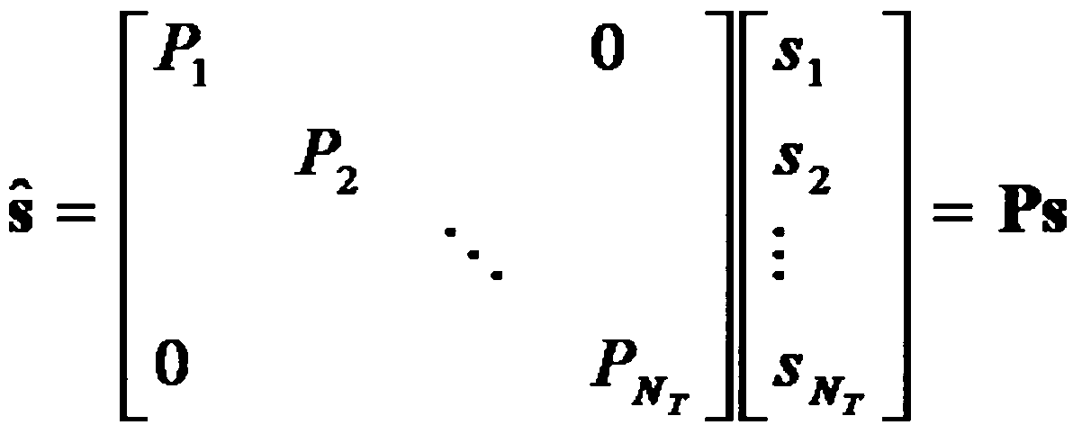
한편, 전송 전력이 조정된 정보 벡터 는 그 후 가중치 행렬 W가 곱해져 실제 전송되는 NT개의 전송 신호 x1, x2, ..., ![]()
![]()
![]()
![]()

상기 수학식 5에서, wij는 i번째 송신 안테나와 j번째 전송 정보간의 가중치를 나타내며, W는 이를 행렬로 나타낸 것이다. 이와 같은 행렬 W를 가중치 행렬(Weight Matrix) 또는 프리코딩 행렬(Precoding Matrix)라 부른다.In Equation (5), wij denotes a weight between the i-th transmission antenna and the j-th transmission information, and W denotes a matrix thereof. Such a matrix W is called a weight matrix or a precoding matrix.
한편, 상술한 바와 같은 전송 신호(x)는 공간 다이버시티를 사용하는 경우와 공간 멀티플렉싱을 사용하는 경우로 나누어 생각해 볼 수 있다.Meanwhile, the transmission signal x may be divided into a case of using spatial diversity and a case of using spatial multiplexing.
공간 멀티플렉싱을 사용하는 경우는 서로 다른 신호를 다중화하여 보내게 되므로, 정보 벡터 s의 원소들이 모두 다른 값을 가지게 되는 반면, 공간 다이버시티를 사용하게 되면 같은 신호를 여러 채널 경로를 통하여 보내게 되므로 정보 벡터 s의 원소들이 모두 같은 값을 갖게 된다.When spatial multiplexing is used, different signals are multiplexed and transmitted, so that the elements of the information vector s have different values. On the other hand, when the spatial diversity is used, the same signal is transmitted through various channel paths, The elements of vector s all have the same value.
물론, 공간 멀티플렉싱과 공간 다이버시티를 혼합하는 방법도 고려 가능하다. 즉, 예를 들어 3 개의 송신 안테나를 통하여 같은 신호를 공간 다이버시티를 이용하여 전송하고, 나머지는 각각 다른 신호를 공간 멀티플렉싱하여 보내는 경우도 고려할 수 있다. 다음으로, 수신신호는 NR개의 수신 안테나가 있는 경우, 각 안테나의 수신신호 y1, y2, ..., ![]()
![]()

한편, 다중 안테나 통신 시스템에 있어서의 채널을 모델링하는 경우, 채널은 송수신 안테나 인덱스에 따라 구분할 수 있으며, 송신 안테나 j로부터 수신 안테나 i를 거치는 채널을 hij로 표시하기로 한다. 여기서, hij의 인덱스의 순서가 수신 안테나 인덱스가 먼저, 송신안테나의 인덱스가 나중임에 유의한다. 이러한 채널은 여러 개를 한데 묶어서 벡터 및 행렬 형태로도 표시 가능하다. 벡터 표시의 예를 들어 설명하면 다음과 같다.Meanwhile, when a channel is modeled in a multi-antenna communication system, a channel can be classified according to a transmission / reception antenna index, and a channel passing from a transmission antenna j to a reception antenna i is denoted by h ij . Here, note that the order of indexes of h ij is the index of the receiving antenna and the index of the transmitting antenna. These channels can be grouped together and displayed in vector and matrix form. An example of a vector representation is as follows.
도 6은 NT개의 송신 안테나에서 수신 안테나 i로의 채널을 도시한 도면이다.6 is a diagram illustrating channels from N T transmit antennas to receive antenna i.
도 6에 도시된 바와 같이, 총 NT개의 송신 안테나로부터 수신안테나 i로 도착하는 채널은 다음 수학식 7과 같이 표현 가능하다.As shown in FIG. 6, a channel arriving from a total of N T transmit antennas to receive antenna i can be expressed as Equation (7).

또한, 상기 수학식 7과 같은 행렬 표현을 통해 NT개의 송신 안테나로부터 NR개의 수신 안테나를 거치는 채널을 모두 나타내는 경우 다음 수학식 8과 같이 나타낼 수 있다.Also, if all the channels passing through the NR receive antennas from the N T transmit antennas are represented by the matrix expression as expressed in Equation (7), the following Equation (8) can be obtained.

한편, 실제 채널은 위와 같은 채널 행렬 H를 거친 후에 백색 잡음(AWGN: Additive White Gaussian Noise)가 더해지게 되므로, NR개의 수신 안테나 각각에 더해지는 백색 잡음 n1, n2, ..., ![]()
![]()

상술한 바와 같은 전송 신호, 수신 신호, 채널, 및 백색 잡음의 모델링을 통해 다중 안테나 통신 시스템에서의 각각은 다음 수학식 10과 같은 관계를 통해 나타낼 수 있다.Through modeling of the transmission signal, the received signal, the channel, and the white noise as described above, each in the multi-antenna communication system can be represented by the following relationship (10).

한편, 채널의 상태를 나타내는 채널 행렬 H의 행(row)과 열(column)의 수는 송수신 안테나 수에 의해서 결정된다. 채널 행렬 H는 앞서 살펴본 바와 같이 행의 수는 수신 안테나의 수 NR과 같아지고, 열의 수는 송신 안테나의 수 NT와 같아지게 된다. 즉, 채널 행렬 H는 NR×NT 행렬이 된다.On the other hand, the number of rows and columns of the channel matrix H indicating the state of the channel is determined by the number of transmitting and receiving antennas. As described above, the number of rows is equal to the number of reception antennas NR, and the number of columns is equal to the number of transmission antennas NT. That is, the channel matrix H becomes an NR x NT matrix.
일반적으로, 행렬의 랭크(rank)는 서로 독립인(independent) 행 또는 열의 개수 중에서 최소 개수로 정의된다. 따라서, 행렬의 랭크는 행 또는 열의 개수보다 클 수 없게 된다. 수식적으로 예를 들면, 채널 행렬 H의 랭크(rank(H))는 다음 수학식 11과 같이 제한된다.In general, the rank of a matrix is defined as the minimum number of independent rows or columns. Thus, the rank of the matrix can not be greater than the number of rows or columns. For example, the rank (rank (H)) of the channel matrix H is limited as shown in Equation (11).
![]()
![]()
이하에서 이동통신 시스템에서 송신단 및 수신단 사이에서 송수신되는 참조신호(Reference Signal, RS)에 대해 설명한다.Hereinafter, a reference signal (RS) transmitted and received between a transmitting end and a receiving end in a mobile communication system will be described.
이동통신 시스템에서 송신단이 수신단으로 패킷(혹은 신호)을 전송할 때, 송신단이 전송하는 패킷은 무선 채널을 통해서 전송되기 때문에 전송과정에서 신호의 왜곡이 발생할 수 있다. 이렇게 왜곡된 신호를 수신단에서 올바로 수신하기 위해서, 수신단은 채널 정보를 알아내어 수신 신호에서 그 채널 정보만큼 전송 신호의 왜곡을 보정함으로써 올바른 신호를 수신할 수 있는 것이다. 이렇게 채널의 정보를 알아내기 위해서는 송신단과 수신단에서 모두 알고 있는 신호를 전송할 필요가 있다. 즉, 수신단에서 알고 있는 신호가 채널을 통해 수신될 때 그 신호의 왜곡 정도를 가지고 채널의 정보를 알아내는 방법을 주로 사용하는데, 이때 전송되는 송신측과 수신측이 모두 알고 있는 신호를 참조신호 또는 파일럿 신호 (Pilot Signal)라고 한다.In a mobile communication system, when a transmitting terminal transmits a packet (or a signal) to a receiving terminal, a packet transmitted by the transmitting terminal is transmitted through a wireless channel, so that a signal may be distorted during transmission. In order to correctly receive the distorted signal at the receiving end, the receiving end can receive the correct signal by determining the channel information and correcting the distortion of the transmission signal by the channel information in the received signal. In order to obtain information of the channel, it is necessary to transmit a signal known to both the transmitting end and the receiving end. That is, when a signal known to the receiving end is received through a channel, a method of finding information of the channel with a degree of distortion of the signal is mainly used. At this time, a signal known to both the transmitting end and the receiving end is referred to as a reference signal It is called a pilot signal.
기존에는 송신단이 수신단으로 패킷을 전송할 때, 지금까지 한 개의 송신안테나와 한 개의 수신안테나를 사용했었다. 그러나 또한, 최근 대부분의 이동통신 시스템에서는 다중 송신안테나와 다중 수신안테나를 채택해 송수신 데이터 효율을 향상시킬 수 있는 방법을 사용한다. 이동통신 시스템의 송신단 혹은 수신단에서 용량증대, 통신 성능을 개선하기 위해서 다중안테나를 사용하여 데이터를 송수신하는 경우에, 각 송신안테나 별로 별도의 참조신호가 존재한다. 수신단은 알고 있는 각 송신 안테나 별 참조신호를 이용하여 각 송신안테나로부터 전송된 신호를 잘 수신할 수 있다.In the past, when a transmitting terminal transmits a packet to a receiving terminal, one transmitting antenna and one receiving antenna have been used so far. However, in most recent mobile communication systems, a method of improving transmit / receive data efficiency by employing multiple transmit antennas and multiple receive antennas is used. In the case of transmitting and receiving data using multiple antennas in order to improve the capacity and communication performance at the transmitting end or the receiving end of the mobile communication system, there is a separate reference signal for each transmission antenna. The receiving end can receive the signals transmitted from the respective transmitting antennas by using the known reference signals for the respective transmitting antennas.
이동통신 시스템에서 참조신호는 그 목적에 따라 크게 두 가지로 구분될 수 있다. 참조신호에는 채널 정보 획득을 위한 목적을 위한 것과 데이터 복조를 위해 사용되는 것이 있다. 전자는 단말이 하향링크로의 채널 정보를 획득할 수 있는데 그 목적이 있으므로, 광대역으로 전송될 필요가 있으며, 특정 서브 프레임에서 하향링크 데이터를 수신하지 않는 단말이라도 그 참조신호를 수신하고 측정할 수 있어야 한다. 또한 이러한 채널 측정용 참조신호는 핸드 오버의 측정 등을 위해서도 사용될 수 있다. 후자는 기지국이 하향링크 신호를 전송할 때 해당 자원에 함께 보내는 참조신호로서, 단말은 해당 참조신호를 수신함으로써 채널 추정을 할 수 있고, 따라서 데이터를 복조할 수 있게 된다. 이러한 복조용 참조신호는 데이터가 전송되는 영역에 전송되어야 한다.In a mobile communication system, reference signals can be roughly classified into two types according to their purposes. The reference signal is used for the purpose of obtaining channel information and for data demodulation. Since the former can acquire channel information on the downlink, the former needs to be transmitted in a wide band, and even a terminal that does not receive downlink data in a specific subframe can receive and measure the reference signal. . The reference signal for channel measurement can also be used for measurement of handover and the like. The latter is a reference signal transmitted together with a corresponding resource when the base station transmits the downlink signal. The terminal can perform channel estimation by receiving the reference signal, and thus can demodulate the data. These demodulation reference signals must be transmitted in the area where data is transmitted.
도 7은 이동통신 시스템의 일 예인 3GPP LTE 시스템에서의 참조신호 패턴을 나타낸 도면이다.7 is a diagram illustrating reference signal patterns in a 3GPP LTE system, which is an example of a mobile communication system.
도 7의 (a)는 normal CP(Cyclic Prefix)가 적용된 경우의 참조신호 패턴을 도시한 도면이고, 도 7의 (b)는 extended CP가 적용된 경우의 참조신호 패턴을 도시한 도면이다.FIG. 7A is a diagram showing a reference signal pattern when a normal CP (Cyclic Prefix) is applied, and FIG. 7B is a diagram showing a reference signal pattern when an extended CP is applied.
이동통신 시스템의 일 예인 Release 8 LTE 시스템에서는 유니캐스트 서비스(unicast service)를 위해서 두 가지 종류의 하향링크 참조신호가 정의되어 있다. 채널 상태에 대한 정보 획득 및 핸드오버 등의 측정 등을 공동 참조신호(Common Reference Signal, CRS라)와 데이터 복조를 위해 사용되는 전용 참조신호(Dedicated Reference Signal, DRS) (UE-specific 참조신호에 해당함)라고 불리우는 두 가지의 참조신호가 있다. Release 8 LTE 시스템에서 UE-specific 참조신호는 데이터 복조용으로만 사용되며 CRS는 채널 정보 획득 및 데이터 복조의 두 가지 목적으로 다 사용된다. 이 CRS는 셀-특정(cell-specific) 참조신호로서, 기지국은 광대역에 걸쳐 매 서브 프레임마다 CRS를 전송한다. 셀-특정(Cell-specific) CRS는 기지국의 전송 안테나 개수에 따라서 최대 4개의 안테나 포트에 대한 참조신호가 전송된다.In the
도 7의 (a) 및 도 7의 (b)에 도시된 바와 같이, 4개 안테나 포트에 대한 CRS(1, 2, 3, 4는 각각 안테나 포트 별로의 참조신호인 R0, R1, R2, R3를 나타냄)는 1RB에서 시간-주파수 자원이 중첩되지 않도록 할당된다. LTE 시스템에서 CRS가 시간-주파수 자원에 맵핑될 때에는, 주파수 축에서 한 안테나 포트에 대한 참조신호는 6 RE(Resource Element)당 1개의 RE에 맵핑되어 전송된다. 한 RB가 주파수 축에서 12개의 RE로 구성되어 있으므로 한 안테나 포트에 대한 RE는 한 RB당 2개의 RE가 사용된다.As shown in FIGS. 7A and 7B, the
도 7의 (a) 및 도 7의 (b)에 도시된 바와 같이, DRS("D")는 PDSCH의 단일-안테나 포트 전송을 위해 지원된다. 단말은 상위 계층으로부터 단말-특정(UE-specific) RS가 있는지 없는지에 대한 정보 등을 수신할 수 있다. 데이터 복조가 필요하다면, 단말로 단말-특정(UE-specific) RS가 자원요소를 통해 전송된다. 한편, 자원블록(RS)으로의 RS 매핑 규칙은 다음 수학식 12 내지 수학식 14와 같이 나타낼 수 있다. 다음 수학식 12는 CRS 매핑 규칙을 나타내기 위한 식이다. 그리고, 수학식 13은 normal CP가 적용되는 DRS의 매핑 규칙을 나타내기 위한 식이고, 수학식 14는 extended CP가 적용되는 DRS의 매핑 규칙을 나타내기 위한 식이다.As shown in Figures 7 (a) and 7 (b), DRS ("D") is supported for single-antenna port transmission of the PDSCH. The UE can receive information on whether there is a UE-specific RS from the upper layer or the like. If data demodulation is required, the UE-specific RS is transmitted to the terminal via the resource element. On the other hand, the RS mapping rule to the resource block RS can be expressed by the following equations (12) to (14). Equation (12) is an expression for expressing the CRS mapping rule. Equation (13) is for expressing the mapping rule of the DRS to which the normal CP is applied, and Equation (14) is for expressing the mapping rule of the DRS to which the extended CP is applied.


![]()
![]()

![]()
![]()
상기 수학식 12 내지 수학식 14에서, k 및 p는 각각 부반송파 인덱스 및 안테나 포트를 나타낸다. ![]()
![]()
![]()
![]()
차세대 이동통신 시스템의 표준인 LTE-A 시스템에서는 데이터 전송률 향상을 위해 기존 표준에서는 지원되지 않았던 CoMP(Coordinated Multi Point) 방식, Multi User-MIMO(MU-MIMO) 방식을 지원할 것으로 예상된다. 여기서, CoMP 시스템은 음영 지역에 있는 단말 및 기지국(셀 또는 섹터) 간의 통신성능을 향상시키기 위해 2개 이상의 기지국 혹은 셀이 서로 협력하여 단말과 통신하는 시스템을 말한다.In the LTE-A system, which is a standard of the next generation mobile communication system, Coordinated Multi Point (CoMP) method and Multi User-MIMO (MU-MIMO) method, which are not supported in the existing standard, are expected to be supported. Here, the CoMP system refers to a system in which two or more base stations or cells cooperate with each other to improve communication performance between a terminal and a base station (cell or sector) in a shadow area.
CoMP 방식은 데이터 공유를 통한 협력적 MIMO 형태의 조인트 프로세싱(CoMP-Joint Processing, CoMP-JP) 및 협력 스케줄링/빔포밍(CoMP-Coordinated Scheduling/beamforming, CoMP-CS/CB) 방식으로 구분할 수 있다.The CoMP scheme can be classified into cooperative MIMO joint processing (CoMP-Joint Processing, CoMP-JP) and CoMP-Coordinated Scheduling / Beamforming (CoMP-CS / CB).
하향링크의 경우 조인트 프로세싱(CoMP-JP) 방식에서, 단말은 CoMP를 수행하는 각 기지국으로부터 데이터를 순간적으로 동시에 수신할 수 있으며, 각 기지국으로부터의 수신한 신호를 결합하여 수신 성능을 향상시킬 수 있다. 이와 달리, 협력 스케줄링/빔포밍 방식(CoMP-CS)에서, 단말은 빔포밍을 통해 데이터를 순간적으로 하나의 기지국을 통해서 수신할 수 있다.In the joint processing (CoMP-JP) scheme in the case of downlink, the UE can instantaneously simultaneously receive data from each base station that performs CoMP and can combine received signals from each base station to improve reception performance . Alternatively, in the cooperative scheduling / beamforming scheme (CoMP-CS), the UE can receive data via beamforming through one base station instantaneously.
상향링크의 경우 조인트 프로세싱(CoMP-JP) 방식에서, 각 기지국은 단말로부터 PUSCH 신호를 동시에 수신할 수 있다. 이와 달리, 협력 스케줄링/빔포밍 방식(CoMP-CS)에서, 하나의 기지국만이 PUSCH를 수신하는데 이때 협력 스케줄링/빔포밍 방식을 사용하기로 하는결정은 협력 셀(혹은 기지국)들에 의해 결정된다.In the joint processing (CoMP-JP) scheme in the uplink, each base station can simultaneously receive the PUSCH signal from the terminal. Alternatively, in the cooperative scheduling / beamforming scheme (CoMP-CS), only one of the base stations receives the PUSCH, and the decision to use the cooperative scheduling / beamforming scheme is determined by the cooperating cell (or base stations) .
MU-MIMO 기술은 기지국이 각 안테나 자원을 다른 단말에게 할당하는 것으로, 안테나 별로 고속 데이터 전송률이 가능한 단말을 선택하여 스케줄링하는 방식이다. 이러한 MU-MIMO 방식은 시스템 처리율(system throughput)을 향상시키는 기술이다.In the MU-MIMO technique, a base station allocates each antenna resource to another UE, and selects and schedules a UE capable of a high data rate for each antenna. This MU-MIMO scheme is a technique for improving system throughput.
도 8은 SRS 심볼을 포함하는 상향링크 서브프레임 구성의 일 예를 나타낸 도면이다.8 is a diagram illustrating an example of a configuration of an uplink subframe including an SRS symbol.
도 8을 참조하면, 사운딩 참조신호(Sounding Reference Signal, SRS)는 상향링크 데이터 및/또는 제어 정보 전송과 관련이 없으며, 주로 상향링크 상에서 주파수-선택적 스케줄링이 가능하도록 채널 품질을 평가하는데 사용된다. 그러나, SRS는 최근에 스케줄링되지 않은 단말에 대해서는 다양한 기능들을 제공하거나 전력 제어를 향상시키는 등과 같은 다른 목적으로 사용될 수도 있다. SRS는 상향링크 채널 측정에 사용되는 참조신호로, 각 단말이 기지국으로 전송하는 파일럿 신호로서, 각 단말로부터 기지국까지의 채널 상태를 기지국이 추정하는데 이용된다. SRS를 전송하는 채널은 각 단말 상태에 따라 각 단말마다 서로 다른 전송 대역폭 및 전송 주기를 가질 수 있다. 채널 추정 결과를 바탕으로 기지국은 매 서브프레임마다 어떤 단말의 데이터 채널을 스케줄링할 것인지 여부를 결정할 수 있다.Referring to FIG. 8, a sounding reference signal (SRS) is not related to uplink data and / or control information transmission, and is mainly used to evaluate channel quality so that frequency-selective scheduling is possible on the uplink . However, the SRS may be used for other purposes such as providing various functions or improving power control for recently unscheduled terminals. SRS is a reference signal used for uplink channel measurement, and is a pilot signal transmitted from each terminal to a base station, and is used by a base station to estimate a channel state from each terminal to a base station. The channel for transmitting the SRS may have a different transmission bandwidth and transmission period for each terminal according to the state of each terminal. Based on the channel estimation result, the base station can determine which UE's data channel to schedule in each subframe.
무선채널은 상향링크 및 하향링크 간에 상호적 관계(reciprocal)에 있다는 가정하에서 SRS는 하향링크 채널 품질을 추정하는데 사용될 수 있다. 이러한 가정은 상향링크와 하향링크가 동일한 주파수 영역을 공유하며 시간 영역에서는 분리된 시간 분할 듀플렉스(Time Division Duplex, TDD) 시스템에서 유효하다. 셀 내 단말에 의해 SRS가 전송되는 서브프레임은 셀-특정(cell-specific) 방송 시그널링에 의해 지시된다. 4 비트 크기의 셀-특정 ' srsSubframeConfiguration' 파라미터가 각 무선 프레임 내에서 SRS가 전송될 수 있는 15개의 가능한 서브프레임 세트를 지시한다. 이러한 구성은 SRS 오버헤드를 조정하는데 있어 유연성을 제공한다. 도 8에 도시한 바와 같이, 단말은 SRS를 구성된 서브프레임에서 마지막 SC-FDMA 심볼을 통해 전송할 수 있다.Under the assumption that the radio channel is reciprocal between the uplink and the downlink, the SRS can be used to estimate the downlink channel quality. This assumption is valid in a time division duplex (TDD) system in which the uplink and downlink share the same frequency domain and are separated in the time domain. The subframe in which the SRS is transmitted by the UE in the cell is indicated by cell-specific broadcast signaling. A 4-bit cell-specific ' srsSubframeConfiguration' parameter indicates 15 possible subframe sets within which each SRS can be transmitted. This configuration provides flexibility in adjusting the SRS overhead. As shown in FIG. 8, the UE can transmit the SRS through the last SC-FDMA symbol in the configured subframe.
따라서, SRS 및 데이터 복조용 참조신호(DeModulation-Reference Signal, DM-RS)는 서브프레임에서 서로 다른 SC-FDMA 심볼에 위치하게 된다. 동일한 서브프레임의 마지막 SC-FDMA로 전송되는 여러 단말의 사운딩 참조신호들은 주파수 위치에 따라 구분이 가능하다. 단말의 PUSCH 데이터는 SRS를 위해 설계된 SC-FDMA 심볼을 통해서는 전송되지 않기 때문에, 최악의 경우 매 서브프레임 마다 SRS 심볼을 가짐으로써 7%의 사운딩 오버헤드가 발생하게 된다.Therefore, the SRS and the demodulation-reference signal (DM-RS) for data demodulation are located in different SC-FDMA symbols in the subframe. The sounding reference signals of the UEs transmitted in the last SC-FDMA of the same subframe can be classified according to frequency positions. Since the PUSCH data of the UE is not transmitted through the SC-FDMA symbol designed for SRS, in the worst case, 7% of the sounding overhead is generated by having the SRS symbol in every subframe.
SRS는 카작(Constant Amplitude Zero Auto Correlation, CAZAC) 시퀀스 등에 의해서 생성되며, 여러 단말로부터 전송된 사운딩 참조신호들은 아래 수학식 15에 따른 서로 다른 순환 천이(cyclic shift) 값(α)을 갖는 CAZAC 시퀀스(![]()
![]()
![]()
![]()

여기서 ![]()
![]()
도 9는 프리코딩되지 않은 전체 랭크 SRS 전송의 일 예를 나타낸 도면이다.9 is a diagram illustrating an example of full rank SRS transmission that is not precoded.
도 9를 참조하면, NUE개의 안테나를 갖는 단말은 프리코딩되지 않은 전체 랭크(non-precoded full rank) SRS를 전체 채널 상태의 추정을 위한 용도로 서빙 기지국으로 전송할 수 있다. 이러한 동작을 위해서, 서로 다른 안테나 포트의 SRS는 서로 다른 SRS 전송 자원에 의해 구분될 수 있다. 즉 각 안테나의 SRS는 시간이나 시퀀스로 구분되어 전송된다. 이렇게 구분되어, 전체 NUE개의 SRS가 전송될 수 있다.Referring to FIG. 9, a UE having N UE antennas can transmit a non-precoded full rank SRS to the serving BS for the purpose of estimating the total channel state. For this operation, the SRSs of different antenna ports can be distinguished by different SRS transmission resources. That is, the SRS of each antenna is divided into time and sequence. Thus, a total of N UE SRSs can be transmitted.
본 발명에서는 도 9와는 달리, CoMP 동작이 프리코딩된 SRS에 기반하여 수행되는 방법에 대해 설명할 것이다. CoMP 동작 세트(즉, CoMP 협력 동작에 관여하는 기지국들(또는 셀, 섹터들))에서 SRS 전송 특징이 각 SRS 수신 포인트들(즉, 수신 기지국들)에 다르다. SRS 전송 특징에는 단말이 SRS를 전송하는 시간, 단말이 SRS 전송을 위해 사용하는 SRS 자원들의 위치 및 자원량, SRS 전송을 위해 사용되는 안테나 포트 수, SRS 전송을 위해 단말에 의해 사용되는 프리코딩 행렬 등이 포함되어 있다.In the present invention, unlike FIG. 9, a method in which a CoMP operation is performed based on precoded SRS will be described. The SRS transmission characteristics in the CoMP operation set (i.e., the base stations (or cells, sectors) involved in the CoMP cooperative operation) are different for each SRS receiving point (i.e., receiving base stations). The SRS transmission characteristics include the time when the terminal transmits the SRS, the location and amount of SRS resources used by the terminal for SRS transmission, the number of antenna ports used for SRS transmission, the precoding matrix used by the terminal for SRS transmission .
본 발명의 일 실시예로서, CoMP 동작을 수행하는 CoMP 단말은 서빙 기지국으로 프리코딩되지 않은 전체 랭크(non-precoded full rank) SRS를 전송하여 서빙 기지국이 채널 추정을 용이하게 하도록 할 수 있다. 한편, 서빙 기지국으로부터 오는 단말의 원하는 신호의 방향을 협력 기지국(coordinating eNB)에 알려주기 이하여 협력 기지국으로 적절하게 프리코딩된 SRS를 전송한다.As one embodiment of the present invention, the CoMP UE performing the CoMP operation may transmit a non-precoded full rank SRS to the serving BS so that the serving BS can facilitate the channel estimation. Meanwhile, a coordinating base station (coordinating eNB) is notified of a desired signal direction of a terminal coming from the serving base station, and then the precoding SRS is appropriately transmitted to the cooperative base station.
본 발명의 다른 실시예로서, 프리코딩된 SRS 레이어(layer)들의 일부(PUSCH 전송의 레이어들에 대응하는 일부 레이어)는 서빙 기지국 및 협력 기지국(혹은 인접 기지국)이 SRS 자원을 이용하여 모두가 수신할 수 있으며, 이때 셀에서 사용되는 모든 SRS 자원은 직교이다. 한편, 나머지 SRS 레어어들은 단지 서빙 기지국만이 수신한다. 이러한 실시예들에서, 단말은 서빙 기지국에 전체 랭크 SRS 정보를 제공하지만 협력 기지국에게는 단지 채널 방향 정보만을 전송할 수 있다.In another embodiment of the present invention, some of the precoded SRS layers (some layers corresponding to the layers of the PUSCH transmission) are received by the serving base station and the cooperative base station (or neighbor base station) , Where all SRS resources used in the cell are orthogonal. On the other hand, only the serving base station receives the remaining SRS pairs. In these embodiments, the terminal may provide full rank SRS information to the serving base station, but only the channel direction information to the cooperative base station.
도 10은 프리코딩된 전체 랭크 SRS 전송의 일 예를 나타낸 도면이다.10 is a diagram illustrating an example of precoded full rank SRS transmission.
도 10을 참조하면, 각 SRS는 프리코딩 행렬 에 의해 프리코딩되고, ![]()
![]()
![]()
![]()
![]()
![]()
도 11은 CoMP 협력 기지국의 협력 동작의 개념을 설명하기 위해 나타낸 도면이다.11 is a diagram for explaining the concept of cooperative operation of CoMP cooperation base stations.
CoMP 협력 기지국이라 함은 인접 셀 간에서 셀 간 간섭을 제거하기 위해 하향링크 및/또는 상향링크에서 CoMP 동작을 수행하는 기지국들을 말한다. 도 11에는 두 개의 CoMP 협력 기지국(혹은 셀)이 도시되어 있다. 하나의 CoMP 협력 기지국은 CoMP 동작을 수행하는 CoMP 단말의 전송/수신을 제어하는 서빙 기지국(1120)이며 다른 하나의 CoMP 협력 기지국은 서빙 기지국과 함께 협력하여 자신의 전송/수신을 제어하기 위한 협력 기지국(1170)이다. 도 11에서는 설명의 편의를 위해 CoMP 협력 기지국으로 두 개의 CoMP 협력 기지국만을 도시하고 있으나, CoMP 협력 기지국의 수가 두 개로 제한되는 것은 아니며, 그 이상의 수로 확장될 수 있다.CoMP cooperative base station refers to a base station that performs CoMP operation on the downlink and / or uplink to remove inter-cell interference between adjacent cells. FIG. 11 shows two CoMP cooperative base stations (or cells). One CoMP cooperation base station controls the transmission / reception of the CoMP terminal performing the CoMP operation, and the other CoMP cooperation base station cooperates with the serving base station to transmit / (1170). In FIG. 11, only two CoMP cooperating base stations are shown as CoMP cooperating base stations for convenience of explanation, but the number of CoMP cooperating base stations is not limited to two, but can be extended to more.
이하에서 도 11에 도시한 바와 같이, 단말 및 CoMP 협력 기지국들 간의 CoMP 협력 동작에 대해 기술한다.Hereinafter, as shown in FIG. 11, a cooperative cooperation operation between a terminal and CoMP cooperation base stations will be described.
하향링크 CoMP 제 1 실시예Downlink CoMP < RTI ID = 0.0 >
하향링크 채널 정보는 채널 간의 상호성(reciprocity)에 의해 SRS 전송/수신을 통해 획득할 수 있다. 이 경우에, 하향링크 CoMP CS/CB는 CoMP 협력 기지국 간에 채널 정보를 교환할 필요가 없기 때문에 본 발명에서 쉽게 구현될 수 있다. 하향링크에서의 CoMP CS/CB 동작을 위한 절차를 이하에서 살펴본다.The downlink channel information can be acquired through SRS transmission / reception by reciprocity between channels. In this case, the downlink CoMP CS / CB can be easily implemented in the present invention since there is no need to exchange channel information between the CoMP cooperation base stations. The procedures for the CoMP CS / CB operation in the downlink will be described below.
도 12는 CoMP 협력 동작을 수행하는 단말과 기지국 간들 간의 하향링크 CoMP CS/CB 동작을 위한 절차의 일 예를 나타낸 도면이다.12 is a diagram illustrating an example of a procedure for downlink CoMP CS / CB operation between a UE and a base station performing CoMP cooperation operation.
먼저, CoMP 단말 중 하나인 단말 3(1150)은 서빙 기지국(1120)으로 프리코딩되지 않은 전체 랭크(full rank) SRS를 전송한다(S1210). 이때 SRS 전송은 동일한 셀(1110)에 위치하는 단말들(1130, 1140)의 SRS와 다중화되어 전송될 수 있다(S1210). 그러면, 서빙 기지국(1120)은 수신한 SRS를 이용하여 단말 3(1150)과 자신 간의 하향링크 채널 HSC을 추정하고, 단말 3(1150)으로의 PDSCH 전송을 위해 사용할 프리코딩 행렬 PSC를 결정할 수 있다(S1220). 도시하지는 않았지만, 서빙 기지국(1120) 결정된 프리코딩 행렬 PSC를 단말 3(1150)에게 알려줄 수 있다. 그 후, 단말 3(1150)은 프리코딩 행렬 PSC에 따라 수신 행렬(또는 포스트코딩 행렬(postcoding matrix), 수신 빔포밍 행렬(receive beamformong matrix) 등으로 호칭될수 있음 ) ![]()
![]()
일반적으로, 단말과 기지국 간에 추정된 하향링크 채널 행렬과 상향링크 채널 행렬과는 허미션(Hermitian) 관계에 있다. 따라서, 단말 3(1150)은 하향링크 및 상향링크 채널 간에 채널 행렬 관점에서 허미션 관계에 있는 상호성에 기반하여 결정된 포스트코딩 행렬 ![]()
![]()
![]()
![]()
협력 기지국(1170)이 단말 3(1150)으로부터 SRS를 수신한 후 유효 인접 채널 행렬 ![]()
![]()
![]()
![]()
![]()
![]()
그 후, 협력 기지국(1170)은 단말 3(1150)에 셀 간 간섭을 심각하게 유발하지 않도록 자신으로부터 서빙받는 단말 4(1180) 및 단말 5(1190)들로 전송할 프리코딩 행렬을 결정할 수 있다(S1260). 일 예로서, 협력 기지국(1170)은 간섭을 야기하지 않기 위하여 유효 인접 채널 ![]()
![]()
도 12와 관련하여 설명한 내용은 상황에 따라 수정될 수 있다. 예를 들어, S1240 단계에서 단말 3(1150)의 SRS 전송을 구성하기 위해, 서빙 기지국(1120)은단말 3(1150)으로 제어 신호를 전송할 수 있다. 이러한 서빙 기지국(1120)이 전송하는 제어 신호는 SRS 랭크 정보, 프리코딩 행렬 정보, 전송 파워 정보, 전송 시간 예(transmission time instance) 정보, SRS 시그너처(signature), SRS 호핑 패턴(hopping pattern) 정보 등을 포함할 수 있다.The contents described with reference to Fig. 12 can be modified depending on the situation. For example, in step S 1240, the serving
이러한 동작을 용이하게 하기 위하여, 인접 셀(또는 협력 기지국)로의 SRS 전송을 위한 일부 자원을 예약해 둘 필요가 있다. 예를 들어, S1240 단계에서, 단말 3(1150)은 프리코딩된 SRS을 사전에 결정된 자원(시간, SRS 시그너처(signature) 등)을 이용하여 전송할 수 있다. 여기서 사전에 결정된 자원이라 함은 롱-텀(long-term) 신호 교환을 통해 협력 기지국(1170)으로 SRS 전송을 위해 예약된 자원이다. 이러한 경우에, 협력 기지국(1170)은 어떤 단말의 채널에서 CoMP CS/CB 동작에서 고려되어야하는지에 대해 쉽게 알 수 있다.To facilitate this operation, it is necessary to reserve some resources for SRS transmission to a neighboring cell (or cooperative base station). For example, in step S1240, terminal 3 1150 may transmit the precoded SRS using a predetermined resource (time, SRS signature, etc.). Where the predetermined resource is a resource reserved for SRS transmission to the
또한, CoMP 단말들로의 PDSCH 전송을 위해 사용될 자원은 협력 셀들(즉, CoMP 동작을 수행하는 협력 기지국들) 간에 빈번한 스케줄링 정보 교환을 피하기 위하여 반-고정적으로(semi-statically) 결정될 수 있다. 이 경우에, S1240 단계에서, 단말 3(1150)이 ![]()
![]()
하향링크 CoMP 제 2 실시예Downlink CoMP < RTI ID = 0.0 >
도 13은 CoMP 협력 동작을 수행하는 단말과 기지국 간들 간의 하향링크 CoMP CS/CB 동작을 위한 절차의 일 예를 나타낸 도면이다.13 is a diagram illustrating an example of a procedure for a downlink CoMP CS / CB operation between a UE and a base station performing CoMP cooperation operation.
먼저, CoMP 단말 중 하나인 단말 3(1150)은 서빙 기지국(1120)으로의 우세 채널 방향(dominant channel direction)에 기초하여 수신 행렬 ![]()
![]()
![]()
![]()
단말 3(1150)은 수신 행렬 ![]()
![]()
서빙 기지국(1120) 및 협력 기지국(1170)은 S1320 단계에서 SRS를 수신함으로써 각각 유효 채널 ![]()
![]()
![]()
![]()
![]()
![]()
![]()
![]()
그 후, 서빙 기지국(1120)은 수신한 SRS를 이용하여 자신과 단말 3(1150) 간의 하향링크 유효 채널 행렬인 ![]()
![]()
한편, 협력 기지국(1170)은 단말 3(1150)에 심각한 셀 간 간섭 영향을 주지 않도록, 자신에게 서빙받는 단말들(예를 들어, 단말 4(1180) 및 단말 5(1190))로 전송할 프리코딩 행렬을 결정할 수 있다(S1350). 일 예로서, 협력 기지국(1170)이 간섭을 유발하지 않기 위하여 전송할 프리코딩 행렬을 유효 인접 채널(effective neighboring channel) ![]()
![]()
상향링크 CoMP 제 1 실시예Uplink CoMP < RTI ID = 0.0 >
앞서 설명한 하향링크 CoMP 동작과 마찬가지로, 상향링크에서도 동일한 방식으로 상향링크 CoMP CS/CB 방식이 적용될 수 있다. 이하 첨부된 도면을 참조하여 상향링크 CoMP CS/CB 동작을 위한 절차를 설명한다.As in the downlink CoMP operation described above, the uplink CoMP CS / CB scheme can be applied in the same manner also in the uplink. Hereinafter, a procedure for an uplink CoMP CS / CB operation will be described with reference to the accompanying drawings.
도 14는 CoMP 협력 동작을 수행하는 단말과 기지국 간들 간의 상향링크 CoMP CS/CB 동작을 위한 절차의 일 예를 나타낸 도면이다.FIG. 14 is a diagram illustrating an example of a procedure for uplink CoMP CS / CB operation between a UE and a base station performing CoMP cooperation operation.
도 14를 참조하면, CoMP 단말 중 하나인 단말 3(1150)은 서빙 기지국(1120)으로 프리코딩되지 않은 전체 랭크(full rank) SRS를 전송한다(S1410). 그러면, 서빙 기지국(1120)은 단말 3(1150)으로부터 수신한 SRS를 이용하여 자신과 단말 3(1150) 간의 상향링크 채널 행렬 HCS를 추정하고, 단말 3(1150)이 PUSCH 전송을 위해 사용할 프리코딩 행렬 PCS를 결정할 수 있다(S1420). 그리고, 서빙 기지국(1120)은 PDCCH 등과 같은 제어 채널을 통해 결정된 프리코딩 행렬 PCS 를 단말 3(1150)으로 전송해줄 수 있다(S1430).14, the
그러면, 단말 3(1150)은 프리코딩 행렬 PCS 를 이용하여 프리코딩된 SRS를 협력 기지국(1170)으로 전송할 수 있다(S1440). 이 SRS 전송은 협력 기지국(1170)이 속하는 셀(1160)에 위치하는 단말들(1180, 1190)의 SRS와 다중화되어 전송될 수 있다(S1440).Then, the
협력 기지국(1170)은 단말 3(1150)으로부터 SRS를 수신하여 프리코딩된 행렬 PCS 를 획득하고, 획득한 프리코딩 행렬 PCS 과 협력 기지국(1170)과 단말 3(1150) 간의 상향링크 채널 행렬을 나타내는 ![]()
![]()
![]()
![]()
그리고, 협력 기지국(1170)은 PUSCH 전송이 단말 3(1150)의 상향링크 전송에 의해 간섭을 받지 않도록 하기 위해 자신의 셀(1160) 내에서 PUSCH 전송을 스케줄링할 단말과 해당 단말의 PUSCH 전송을 위한 프리코딩 행렬을 결정할 수 있다(S1460).In order to prevent the PUSCH transmission from being interfered by the uplink transmission of the
이러한 동작을 용이하게 하기 위하여, 인접 셀(또는 협력 기지국)로의 SRS 전송을 위한 일부 자원을 예약해 둘 필요가 있다. 예를 들어, S1440 단계에서, 단말 3(1150)은 프리코딩된 SRS를 사전에 결정된 자원(시간, SRS 시그너처(signature) 등)을 이용하여 전송할 수 있다. 여기서 사전에 결정된 자원이라 함은 롱-텀(long-term) 신호 교환을 통해 협력 기지국(1170)으로 SRS 전송을 위해 예약된 자원이다. 이러한 경우에, 협력 기지국(1170)은 어떤 단말의 채널의 CoMP CS/CB 동작에서 고려되어야하는지에 대해 쉽게 알 수 있다. 또한, CoMP 단말들로의 PDSCH 전송을 위해 사용딜 자원은 협력 셀들(즉, CoMP 동작을 수행하는 협력 기지국들) 간에 빈번한 스케줄링 정보 교환을 피하기 위하여 반-고정적으로(semi-statically) 결정될 수 있다. 이 경우에, S1430 단계에서, 단말 3(1150)이 프리코딩된 SRS를 협력 기지국(1170)으로 전송할 때, 전체 대역폭에서가 아니라 CoMP 동작을 위해 예약된 한정적인 주파수 자원을 통해 전송할 수 있다.To facilitate this operation, it is necessary to reserve some resources for SRS transmission to a neighboring cell (or cooperative base station). For example, in step 1440,
상기 제안한 방식을 이용하면, 백홀 링크 지연(backhaul link delay)이 큰 경우에도 협력 기지국(1170)에 CoMP 단말(예를 들어, 단말 3(1150))과 협력 기지국(1170) 간의 유효 채널 정보를 효과적으로 전달할 수 있다. 그러나, 협력 기지국(1170)이 CoMP CS/CB 등의 CoMP 동작을 수행하기 위해서 유효 채널(effective channel)과 더불어 CoMP 단말의 스케줄링 정보가 필요하다.Using the proposed scheme, the effective channel information between the CoMP terminal (for example, terminal 3 1150) and the
앞서 설명한 내용에서는 이를 위한 한 가지 방법으로, CoMP 단말의 PUSCH 전송을 위한 시간, 주파수 자원을 반-고정적으로(semi-statically) 설정함으로써 백홀 링크를 통한 CoMP 단말 스케줄링 정보 공유를 최소화할 수 있다.As described above, sharing the CoMP UE scheduling information through the backhaul link can be minimized by semi-statically setting the time and frequency resources for the PUSCH transmission of the CoMP UE.
이와 같은, 반-고정적으로(semi-statically) PUSCH 전송을 위한 자원을 결정하는 기법을 통해 CoMP 동작에 참여하는 셀 간의 정보 공유는 간단하게 해결할 수 있지만, 스케줄링 제한이 발생함에 따라 CoMP 단말의 통신성능이 감소할 수 있다. 이러한 문제를 해결하기 위해 CoMP 단말의 스케줄링 정보를 공유하기 위한 또 다른 방법을 설명한다. 즉, 별도의 시그널링 없이 SRS 구성(configuration)을 이용하여 협력 기지국에 CoMP 단말의 스케줄링 정보를 알려 주는 것을 제안한다.The sharing of information among the cells participating in the CoMP operation can be easily solved through the technique of determining the resources for semi-statically PUSCH transmission, but as the scheduling restriction occurs, the communication performance of the CoMP UE Can be reduced. To solve this problem, another method for sharing the scheduling information of CoMP terminals will be described. That is, it is proposed to inform the cooperative base station of the scheduling information of the CoMP UE using the SRS configuration without signaling.
일 예로서, CoMP 단말 스케줄링 정보에 따라 CoMP 단말이 셀 간 약속된 SRS 구성으로 프리코딩된 SRS를 전송하여, 협력 기지국에 스케줄링 정보를 암시적으로(implicitly)하게 알려 줄 수 있다. SRS 구성 정보에는 SRS 호핑 패턴(Hopping pattern), 콤브 인덱스(comb index), 시퀀스 옵셋(sequence offset), SRS 전송 서브프레임 번호(transmission subframe number), 전송되는 SRS 자원블록(RB)등 다양한 파라미터를 포함할 수 있다. 이러한 전체 혹은 일부 파라미터를 CoMP 단말 스케줄링 정보와 연동하여 설정할 수 있다. 일 예로서 다음 도 15를 참조하여 설명한다.For example, according to the CoMP UE scheduling information, the CoMP UE may transmit the precoded SRS to the inter-cell promised SRS configuration and notify the cooperative base station of the scheduling information implicitly. The SRS configuration information includes various parameters such as an SRS hopping pattern, a comb index, a sequence offset, an SRS transmission subframe number, and an SRS resource block (RB) to be transmitted can do. All or some of these parameters can be set in conjunction with the CoMP terminal scheduling information. An example will be described with reference to FIG.
하향링크 CoMP 제 3 실시예Third Embodiment of Downlink CoMP
도 15는 CoMP 협력 동작을 수행하는 단말과 기지국 간들 간의 하향링크 CoMP CS/CB 동작을 위한 절차의 다른 예를 나타낸 도면이다.FIG. 15 is a diagram illustrating another example of a procedure for downlink CoMP CS / CB operation between a terminal and a base station performing CoMP cooperation operation.
도 15를 참조하면, 단말 3(1150)은 프리코딩되지 않은 전체 랭크(full rank) SRS를 서빙 기지국(1120)으로 전송한다(S1510). 이때 SRS 전송은 동일한 셀(1110)에 위치하는 단말들(1130, 1140)의 SRS와 다중화되어 전송될 수 있다(S1510). 그러면, 서빙 기지국(1120)은 수신한 SRS를 이용하여 단말 3(1150)과 자신 간의 하향링크 채널 HSC을 추정하고, 단말 3(1150)으로의 PDSCH 전송을 위해 사용될 프리코딩 행렬 PSC과 주파수, 시간 자원을 결정한다(S1520). 그 후, 서빙 기지국(1120)은 S1520 단계에서 결정된 스케줄링 정보(예를 들어, 시간, 주파수 자원 정보)에 기초하여 단말 3(1150)을 포함하는 CoMP 단말들의 프리코딩된 SRS 전송을 구성할 수 있다(S1530).Referring to FIG. 15, the
그 후, 서빙 기지국(1120)은 SRS 구성 정보를 단말 3(1150)에게 시그널링해 줄 수 있다(S1540). 이때, 서빙 기지국(1120)이 단말 3(1150)에게 시그널링해주는 내용에는 협력 기지국(1170)과 서빙 기지국(1120)이 공유하고 있는 SRS 구성 규칙에 의해 만들어진 SRS 구성(configuratioin) 및 단말 3(1150)으로의 PDSCH 전송을 위해 사용할 프리코딩 행렬 Psc 가 포함될 수 있다.After that, the serving
단말 3(1150)은 프리코딩 행렬 PSC에 따라 수신 행렬(또는 포스트코딩 행렬(postcoding matrix), 수신 빔포밍 행렬(receive beamformong matrix) ) ![]()
![]()
단말 3(1150)은 ![]()
![]()
협력 기지국(1170)은 서빙 기지국(1120)과 공유하고 있는 SRS 구성 규칙을 이용하고 단말 3(1150)으로부터의 SRS를 수신하여, 협력 기지국(1170)은 유효 인접 채널 ![]()
![]()
![]()
![]()
그리고, 협력 기지국(1170)은 단말 3(1150)에 심각한 셀 간 간섭 영향을 주지 않도록, 단말 3(1150)과 중복되는 시간, 주파수 자원을 할당받은 서빙받는 단말들(예를 들어, 단말 4(1180) 및 단말 5(1190))에게 전송할 프리코딩 행렬을 결정할 수 있다(S1580). 일 예로서, 협력 기지국(1170)은 간섭을 유발하지 않기 위하여 단말 3(1150)과 중복되는 시간, 주파수 자원을 할당받은 서빙받는 단말들(예를 들어, 단말 4(1180) 및 단말 5(1190))에게 전송할 프리코딩 행렬을 유효 인접 채널(effective neighboring channel) ![]()
![]()
상향링크 CoMP 제 2 실시예Uplink CoMP Second Embodiment
도 16은 CoMP 협력 동작을 수행하는 단말과 기지국 간들 간의 상향링크 CoMP CS/CB 동작을 위한 절차의 다른 예를 나타낸 도면이다.FIG. 16 is a diagram illustrating another example of procedures for uplink CoMP CS / CB operation between a UE and a base station performing CoMP cooperation operation.
도 16을 참조하면, CoMP 단말 중 하나인 단말 3(1150)은 서빙 기지국(1120)으로 프리코딩되지 않은 전체 랭크(full rank) SRS를 전송한다(S1610). 이때 단말 3(1150)의 SRS 전송은 동일한 셀(1110)에 위치하는 단말들(1130, 1140)의 SRS와 다중화되어 전송될 수 있다(S1610).Referring to FIG. 16, one of the CoMP terminals transmits a full rank SRS not precoded to the serving base station 1120 (S1610). At this time, the SRS transmission of the
그러면, 서빙 기지국(1120)은 단말 3(1150)으로부터 수신한 SRS를 이용하여 자신과 단말 3(1150) 간의 상향링크 채널 행렬 HCS를 추정하고, 단말 3(1150)이 서빙 기지국(1120)으로의 PUSCH 전송을 위해 사용할 프리코딩 행렬 PCS를 결정할 수 있다(S1620). 그리고, 서빙 기지국(1120)은 PDCCH 등과 같은 제어 채널을 통해 상기 결정된 프리코딩 행렬 PCS 및 SRS 구성 정보를 단말 3(1150)으로 전송해줄 수 있다(S1630). 이때, SRS 구성은 CoMP 단말의 스케줄링 결과에 따라 결정되게 된다.Then, the serving
그러면, 단말 3(1150)은 프리코딩 행렬 PCS 를 이용하여 프리코딩된 SRS를 협력 기지국(1170)으로 전송할 수 있다(S1640). 이 SRS 전송은 협력 기지국(1170)이 속하는 셀(1160)에 위치하는 단말들(1180, 1190)의 SRS와 다중화되어 전송될 수 있다(S1640).Then, the
협력 기지국(1170)은 단말 3(1150)으로부터 SRS를 수신하고 서빙 기지국(1120) 간의 공유를 통해 알고 있는 SRS 구성 정보를 적용하여 유효 간섭 채널(effective interference channel) ![]()
![]()
![]()
![]()
그리고, 협력 기지국(1170)은 PUSCH 전송이 단말 3(1150)의 상향링크 전송에 의해 간섭을 받지 않도록 하기 위해 자신의 셀(1160) 내에서 CoMP 단말과 오버랩되는 시간, 주파수 자원을 할당받아 스케줄링된 단말과 PUSCH 전송을 프리코딩 행렬을 결정할 수 있다(S1660). 일 예로서, 협력 기지국(1170)이 간섭을 유발하지 않기 위하여 전송할 PUSCH 프리코딩 행렬의 유효 채널을 유효 인접 채널(effective neighboring channel) ![]()
![]()
CoMP 단말(예를 들어, 단말 3(1150)) 스케줄링 정보에 따른 SRS 구성(configuration) 설정 시, 구체적으로 SRS 구성 파라미터 중 SRS 전송 서브프레임 번호(transmission subframe number)와 SRS가 전송되는 자원블록(RB)을 이용하여 협력 기지국(1170)은 암시적으로 CoMP 단말(예를 들어, 단말 3(1150))의 스케줄링 정보를 알릴 수 있다. 먼저 서빙 기지국(1120)은 협력 기지국(1170)에 할당된 주파수 자원을 암시적으로 알리기 위해 전송되는 SRS RB를 스케줄링된 주파수와 동일하게 설정하고, 스케줄링된 시간 자원 즉 PDSCH 전송 서브프레임 번호를 알리기 위해 SRS 전송 서브프레임 번호를 "PDSCH 전송 서브프레임 수-N" 으로 설정한다(여기서, N은 양의 정수 이며 CoMP 기지국 간의 약속된 값으로 반-고정적(semi-statically)으로 변하거나 고정된 값이다).When an SRS configuration according to the scheduling information of the CoMP UE (for example, the
이와 같이, SRS 구성과 스케줄링을 연동할 경우, CoMP 협력을 수행하는 두 기지국(1120, 1170)의 기존 SRS 구성을 위반하지 않는 범위 내에서 CoMP 단말(예를 들어, 단말 3(1150))의 스케줄링을 수행해야 하므로 스케줄링 제약이 따른다. 즉, CoMP 단말(예를 들어, 단말 3(1150))에게 할당가능한 자원은 모든 PDSCH(상향링크인 경우 PUSCH) 영역이 아니라 시간 축으로는 SRS 전송이 가능한 서브프레임번호 이후 N 번째 서브프레임, 주파수 축으로는 다른 단말들과 충돌 없이 전송 가능한 SRS RB로 제한할 수 있다.When the SRS configuration and the scheduling are interlocked, the scheduling of the CoMP terminal (for example, the
그러나, 이러한 방식은 앞서 언급한 CoMP 단말(예를 들어, 단말 3(1150))의 자원을 반-고정적(semi-statically) 고정시켜 놓는 방식과 비교하면 유연하고 동적인 스케줄링이 가능하다는 장점이 있다. 또한 CSG(Closed Subscribed Group) 셀 등의 마이크로 셀(micro cell)과 매크로 셀(macro cell)이 공존하는 이종 셀 환경에서는 백홀 링크를 통한 CoMP 정보 공유가 어려우며, 강한 셀 간 간섭이 발생하는 것을 감안할 때, 제안된 방식으로 인한 CoMP 이득이 스케줄링 제한(scheduling restriction)으로 인한 성능 감소를 보완할 수 있다.However, this scheme has an advantage that flexible and dynamic scheduling is possible in comparison with a method of semi-statically fixing resources of the CoMP terminal (for example, the third terminal 1150) . Also, it is difficult to share CoMP information through the backhaul link in a heterogeneous cell environment in which a micro cell and a macro cell coexist such as a CSG (Closed Subscribed Group) cell, and strong inter-cell interference occurs , The CoMP gain due to the proposed scheme can compensate for the reduction in performance due to scheduling restrictions.
상기 기술된 실시예에서, 서빙 기지국(1120)이 스케줄링 결과에 따라 CoMP 단말의 SRS를 명시적으로(explicitly) 구성하고 있지만, 이와 달리 CoMP 단말(예를 들어, 단말 3(1150))에 PDSCH를 전송하기 전에 서빙 기지국(1120)이 스케줄링 정보를 PDCCH에 실어 CoMP 단말(예를 들어, 단말 3(1150))에게 사전 통보함으로써 이를 바탕으로 단말이 약속된 SRS 구성 규칙에 맞게 프리코딩된 SRS 전송을 수행할 수 있다. 후자의 경우, 서빙 기지국(1120)이 CoMP 단말(예를 들어, 단말 3(1150))에게 반-고정적으로 변하는 혹은 고정된 N값(즉, SRS 전송 서브프레임 번호(혹은 인덱스))을 알려주어야 하지만, CoMP 단말(예를 들어, 단말 3(1150))의 프리코딩된 SRS 구성을 위해 추가적으로 시그널링을 해줄 필요는 없다.The serving
이상에서 설명된 실시예들은 본 발명의 구성요소들과 특징들이 소정 형태로 결합된 것들이다. 각 구성요소 또는 특징은 별도의 명시적 언급이 없는 한 선택적인 것으로 고려되어야 한다. 각 구성요소 또는 특징은 다른 구성요소나 특징과 결합되지 않은 형태로 실시될 수 있다. 또한, 일부 구성요소들 및/또는 특징들을 결합하여 본 발명의 실시예를 구성하는 것도 가능하다. 본 발명의 실시예들에서 설명되는 동작들의 순서는 변경될 수 있다. 어느 실시예의 일부 구성이나 특징은 다른 실시예에 포함될 수 있고, 또는 다른 실시예의 대응하는 구성 또는 특징과 교체될 수 있다. 특허청구범위에서 명시적인 인용 관계가 있지 않은 청구항들을 결합하여 실시예를 구성하거나 출원 후의 보정에 의해 새로운 청구항으로 포함시킬 수 있음은 자명하다.The embodiments described above are those in which the elements and features of the present invention are combined in a predetermined form. Each component or feature shall be considered optional unless otherwise expressly stated. Each component or feature may be implemented in a form that is not combined with other components or features. It is also possible to construct embodiments of the present invention by combining some of the elements and / or features. The order of the operations described in the embodiments of the present invention may be changed. Some configurations or features of certain embodiments may be included in other embodiments, or may be replaced with corresponding configurations or features of other embodiments. It is clear that the claims that are not expressly cited in the claims may be combined to form an embodiment or be included in a new claim by an amendment after the application.
본 발명은 본 발명의 정신 및 필수적 특징을 벗어나지 않는 범위에서 다른 특정한 형태로 구체화될 수 있음은 당업자에게 자명하다. 따라서, 상기의 상세한 설명은 모든 면에서 제한적으로 해석되어서는 아니 되고 예시적인 것으로 고려되어야 한다. 본 발명의 범위는 첨부된 청구항의 합리적 해석에 의해 결정되어야 하고, 본 발명의 등가적 범위 내에서의 모든 변경은 본 발명의 범위에 포함된다.It will be apparent to those skilled in the art that the present invention may be embodied in other specific forms without departing from the spirit or essential characteristics thereof. Accordingly, the above description should not be construed in a limiting sense in all respects and should be considered illustrative. The scope of the present invention should be determined by rational interpretation of the appended claims, and all changes within the scope of equivalents of the present invention are included in the scope of the present invention.
산업상 이용가능성Industrial availability
프리코딩된 사운딩 참조신호를 이용하여 CoMP(Coordinated Multiple point) 통신을 수행하는 장치 및 그 방법은 3GPP LTE, 3GPP LTE-A, IEEE 802 등과 같은 이동 통신 시스템에서 산업적으로 적용가능 하다.The apparatus and method for performing Coordinated Multiple Point (CoMP) communication using precoded sounding reference signals are industrially applicable in mobile communication systems such as 3GPP LTE, 3GPP LTE-A, and IEEE 802.
Claims (15)
상기 SRS에 프리코딩된 상기 제 1 행렬의 허미션(hermitian) 행렬과 상기 인접 셀의 단말과 상기 기지국 간의 하향링크 채널 행렬을 이용하여 유효 인접 채널(effective neighboring channel) 행렬을 획득하는 단계; 및
상기 유효 인접 채널 행렬에 기초하여 상기 기지국으로부터 서빙받으며, 상기 인접 셀의 단말에 스케줄링된 시간 또는 주파수 자원과 중복되는 자원을 이용하는 하나 이상의 단말에게 전송할 프리코딩 행렬을 결정하는 단계를 포함하되,
상기 유효 인접 채널 행렬은 상기 인접 셀의 단말이 상기 인접 셀의 단말의 서빙 기지국으로부터 데이터 수신을 위해 수신 빔을 향해야 하는 방향을 나타내는 행렬인, 프리코딩된 사운딩 참조신호를 이용하여 CoMP(Coordinated Multiple point) 통신을 수행하는 방법.Receiving a sounding reference signal (SRS) precoded by a first matrix from a terminal of a neighboring cell;
Acquiring an effective neighboring channel matrix using a hermitian matrix of the first matrix precoded in the SRS and a downlink channel matrix between a terminal of the neighboring cell and the base station; And
Determining a precoding matrix to be transmitted to one or more terminals using a resource overlapped with a time or frequency resource scheduled for a terminal of the neighboring cell serving from the base station based on the effective neighboring channel matrix,
Wherein the effective neighboring channel matrix is a Coordinated Multiple (CoMP) signal using a precoded sounding reference signal, which is a matrix indicating a direction in which a UE of the neighboring cell should direct a receive beam to receive data from a serving base station of the UE of the neighboring cell. point communication.
상기 제 1 행렬은 상기 인접 셀의 단말의 서빙 기지국이 결정한 프리코딩 행렬에 기초하여 상기 인접 셀의 단말이 상기 SRS에 적용하기로 결정한 프리코딩 행렬에 해당하는, 사운딩 참조신호를 이용하여 CoMP(Coordinated Multiple point) 통신을 수행하는 방법.The method according to claim 1,
Wherein the first matrix is a CoMP (Co) matrix using a sounding reference signal corresponding to a precoding matrix determined by the UE of the neighboring cell to apply to the SRS, based on a precoding matrix determined by the serving base station of the UE of the neighboring cell A method for performing coordinated multiple point communication.
상기 유효 인접 채널 행렬은 상기 제 1 행렬의 허미션 행렬과, 상기 인접 셀의 단말과 상기 기지국 간의 하향링크 채널 행렬의 곱으로 표현되는, 사운딩 참조신호를 이용하여 CoMP(Coordinated Multiple point) 통신을 수행하는 방법.The method according to claim 1,
The effective neighboring channel matrix is Coordinated Multiple Point (CoMP) communication using a sounding reference signal, which is expressed by a product of a hermetical matrix of the first matrix and a downlink channel matrix between a terminal of the neighboring cell and the base station. How to do it.
상기 수신한 SRS부터 상기 인접 셀의 단말의 CoMP 스케줄링 정보를 획득하는 단계를 더 포함하는, 사운딩 참조신호를 이용하여 CoMP(Coordinated Multiple point) 통신을 수행하는 방법.The method according to claim 1,
And obtaining CoMP scheduling information of the UE of the neighboring cell from the received SRS, in accordance with the Coordinated Multiple Point (CoMP) communication using the sounding reference signal.
상기 결정된 프리코딩 행렬은 상기 유효 인접 채널 행렬의 널 공간(null space) 내에 존재하는, 사운딩 참조신호를 이용하여 CoMP(Coordinated Multiple point) 통신을 수행하는 방법.The method according to claim 1,
Wherein the determined precoding matrix is Coordinated Multiple Point (CoMP) communication using a sounding reference signal existing in a null space of the effective adjacent channel matrix.
상기 수신한 SRS로부터의 제 1 행렬의 허미션(hermitian) 행렬 및 상기 인접 셀의 단말과 기지국 간의 하향링크 채널 행렬을 이용하여 유효 인접 채널(effective neighboring channel) 행렬을 획득하고,
상기 유효 인접 채널 행렬에 기초하여 상기 기지국으로부터 서빙받으며, 상기 인접 셀의 단말에 스케줄링된 시간 또는 주파수 자원과 중복되는 자원을 이용하는 하나 이상의 단말에게 전송할 프리코딩 행렬을 결정하는 프로세서를 포함하되,
상기 유효 인접 채널 행렬은 상기 인접 셀의 단말이 상기 인접 셀의 단말의 서빙 기지국으로부터 데이터 수신을 위해 수신 빔을 향해야 하는 방향을 나타내는 행렬인, 프리코딩된 사운딩 참조신호를 이용하여 CoMP(Coordinated Multiple point) 동작을 수행하는 기지국 장치.A receiver for receiving a sounding reference signal (SRS) precoded by a first matrix from a terminal of a neighboring cell;
Acquiring an effective neighboring channel matrix using a hermit matrix of a first matrix from the received SRS and a downlink channel matrix between a terminal of the neighboring cell and a base station,
And a processor for determining a precoding matrix to be transmitted to one or more mobile stations that are serving from the base station based on the effective neighboring channel matrix and use resources overlapping a scheduled time or frequency resource with the terminal of the neighboring cell,
Wherein the effective neighboring channel matrix is a Coordinated Multiple (CoMP) signal using a precoded sounding reference signal, which is a matrix indicating a direction in which a UE of the neighboring cell should direct a receive beam to receive data from a serving base station of the UE of the neighboring cell. point operation.
Applications Claiming Priority (5)
| Application Number | Priority Date | Filing Date | Title |
|---|---|---|---|
| US28938509P | 2009-12-22 | 2009-12-22 | |
| US61/289,385 | 2009-12-22 | ||
| US32475610P | 2010-04-16 | 2010-04-16 | |
| US61/324,756 | 2010-04-16 | ||
| PCT/KR2010/009195 WO2011078571A2 (en) | 2009-12-22 | 2010-12-22 | Apparatus for performing comp communication using a precoded sounding reference signal, and method for same |
Publications (2)
| Publication Number | Publication Date |
|---|---|
| KR20120112611A KR20120112611A (en) | 2012-10-11 |
| KR101757301B1 true KR101757301B1 (en) | 2017-07-12 |
Family
ID=44196308
Family Applications (1)
| Application Number | Title | Priority Date | Filing Date |
|---|---|---|---|
| KR1020127019019A KR101757301B1 (en) | 2009-12-22 | 2010-12-22 | Apparatus for performing comp communication using a precoded sounding reference signal, and method for same |
Country Status (3)
| Country | Link |
|---|---|
| US (1) | US8737307B2 (en) |
| KR (1) | KR101757301B1 (en) |
| WO (1) | WO2011078571A2 (en) |
Families Citing this family (43)
| Publication number | Priority date | Publication date | Assignee | Title |
|---|---|---|---|---|
| US9184511B2 (en) | 2009-07-10 | 2015-11-10 | Futurewei Technologies, Inc. | System and method for downlink channel sounding in wireless communications systems |
| US8995342B2 (en) | 2009-12-17 | 2015-03-31 | Lg Electronics Inc. | Method of reducing interference between stations in wireless LAN system, and apparatus supporting the same |
| WO2011094926A1 (en) * | 2010-02-02 | 2011-08-11 | Nokia Corporation | Methods and apparatuses for resource mapping for multiple transport blocks over wireless backhaul link |
| WO2012008705A2 (en) * | 2010-07-16 | 2012-01-19 | Lg Electronics Inc. | Transmission method and apparatus for carrier aggregation and uplink mimo |
| US9986388B2 (en) | 2010-10-06 | 2018-05-29 | Unwired Planet International Limited | Method and apparatus for transmitting and receiving data |
| KR101780503B1 (en) * | 2010-10-06 | 2017-09-21 | 언와이어드 플래넷 인터내셔널 리미티드 | Apparatus and method for transmitting and receiving data |
| US9332528B2 (en) * | 2010-11-02 | 2016-05-03 | Lg Electronics Inc. | Method and device for feeding back precoding matrix indicator using interpolation |
| WO2012093449A1 (en) | 2011-01-07 | 2012-07-12 | パナソニック株式会社 | Transmitter, receiver, transmission method, and reception method |
| CN102882657B (en) | 2011-07-15 | 2018-01-23 | 瑞典爱立信有限公司 | Method, apparatus and system for up-link rank adaptation |
| KR20130011441A (en) * | 2011-07-21 | 2013-01-30 | 주식회사 팬택 | Method and apparatus for transmitting control information |
| CN102916762B (en) * | 2011-08-02 | 2017-08-18 | 瑞典爱立信有限公司 | Method and apparatus for being decoded to precoded signal |
| KR101301302B1 (en) | 2011-10-31 | 2013-08-28 | 주식회사 케이티 | System for processing signal and method for processing signal |
| KR101301300B1 (en) * | 2012-01-16 | 2013-08-28 | 주식회사 케이티 | Apparatus for processing digital signal, system for processing signal including same and method for processing signal |
| CN103220101B (en) * | 2012-01-19 | 2018-02-16 | 中兴通讯股份有限公司 | The notice of frequency spectrum comb signaling, the sending method of detection reference signal and device |
| CN104350690A (en) * | 2012-04-13 | 2015-02-11 | 诺基亚公司 | Arrangement for enhanced multi-transmit antenna sounding |
| CN103716079B (en) * | 2012-09-28 | 2017-02-15 | 上海贝尔股份有限公司 | Method and apparatus for coordinated multipoint downlink transmission between two cells |
| US9596065B2 (en) | 2012-10-24 | 2017-03-14 | Qualcomm Incorporated | Enhanced SRS transmission for MIMO operation in LTE-A |
| WO2014088271A1 (en) * | 2012-12-09 | 2014-06-12 | 엘지전자 주식회사 | Method and device for transmitting and receiving signal in multi-cell cooperative communication system |
| CN105122679B (en) * | 2013-04-15 | 2018-09-25 | Lg电子株式会社 | The method and apparatus that detection reference signal is sent in wireless access system |
| EP2989844B1 (en) | 2013-04-24 | 2017-03-15 | Telefonaktiebolaget LM Ericsson (publ) | Method and network node for link adaptation in a wireless communications network |
| KR102216248B1 (en) * | 2013-09-05 | 2021-02-17 | 엘지전자 주식회사 | Method and apparatus for transmitting reference signal in multiple antenna supporting wireless communication system |
| WO2015084105A1 (en) * | 2013-12-05 | 2015-06-11 | 엘지전자 주식회사 | Method and apparatus for transceiving signal in wireless communication system |
| WO2016133437A1 (en) * | 2015-02-19 | 2016-08-25 | Telefonaktiebolaget Lm Ericsson (Publ) | Wireless node, radio node and methods for transmitting and receiving a reference signal |
| EP3275089A1 (en) * | 2015-03-27 | 2018-01-31 | Telefonaktiebolaget LM Ericsson (publ) | Methods and arrangements for mitigating inter-cluster interference |
| US9900901B1 (en) * | 2015-04-22 | 2018-02-20 | Mediatek Inc. | Sounding method and wireless communication system |
| US10257851B2 (en) * | 2015-09-24 | 2019-04-09 | Qualcomm Incorporated | Channel configuration for co-existence on a shared communication medium |
| KR101748814B1 (en) * | 2015-12-29 | 2017-06-19 | 고려대학교 산학협력단 | Apparatus and method for signal trransmitting and receiviing with hibrid beamforming |
| CN106341168B (en) * | 2015-12-31 | 2019-12-03 | 北京智谷睿拓技术服务有限公司 | Method for precoding, method for sending information and its device |
| EP3422617A4 (en) | 2016-03-16 | 2019-03-06 | Huawei Technologies Co., Ltd. | Signal transmission method and device |
| US10511364B2 (en) | 2016-08-03 | 2019-12-17 | Lg Electronics Inc. | Method for transmitting signals in wireless communication system and apparatus therefor |
| WO2018026253A1 (en) * | 2016-08-05 | 2018-02-08 | 엘지전자(주) | Method for transmitting scheduling request in wireless communication system, and apparatus therefor |
| CN110176949A (en) * | 2016-08-12 | 2019-08-27 | 华为技术有限公司 | Data transmission method for uplink, signaling method, apparatus and system |
| WO2018056789A1 (en) * | 2016-09-26 | 2018-03-29 | 엘지전자(주) | Uplink transmission/reception method in wireless communication system and device therefor |
| US10469224B2 (en) * | 2016-09-30 | 2019-11-05 | Qualcomm Incorporated | Joint transmission of precoded and unprecoded sounding reference signals in uplink |
| US10609714B2 (en) * | 2017-07-12 | 2020-03-31 | Qualcomm Incorporated | Spatial listen before talk |
| WO2019139423A1 (en) * | 2018-01-11 | 2019-07-18 | 엘지전자 주식회사 | Method for transmitting or receiving signal to or from user equipment by base station supporting full duplex in wireless communication system |
| US10644771B2 (en) * | 2018-06-08 | 2020-05-05 | University Of South Florida | Using artificial signals to maximize capacity and secrecy of multiple-input multiple-output (MIMO) communication |
| US10516452B1 (en) * | 2018-06-08 | 2019-12-24 | University Of South Florida | Using artificial signals to maximize capacity and secrecy of multiple-input multiple-output (MIMO) communication |
| US10951283B2 (en) * | 2018-08-02 | 2021-03-16 | Qualcomm Incorporated | Paired sounding reference signal transmissions in multi-transmission/reception point operation |
| CN111385823B (en) * | 2018-12-29 | 2023-08-01 | 南京中兴新软件有限责任公司 | Signal processing method and device |
| US11329781B2 (en) * | 2019-02-12 | 2022-05-10 | Qualcomm Incorporated | Sounding reference signal (SRS) transmission in multiple SRS symbols in a subframe |
| CN111836287A (en) * | 2019-04-19 | 2020-10-27 | 索尼公司 | Electronic device, method, and storage medium for wireless communication system |
| CN113260056B (en) | 2020-02-13 | 2022-09-16 | 北京紫光展锐通信技术有限公司 | Uplink data transmission method, user equipment and readable storage medium |
Citations (3)
| Publication number | Priority date | Publication date | Assignee | Title |
|---|---|---|---|---|
| US20110256897A1 (en) | 2008-09-22 | 2011-10-20 | Ntt Docomo, Inc. | Base station apparatus, user equipment and precoding method |
| US20120113950A1 (en) | 2009-07-22 | 2012-05-10 | Peter Skov | Method Of Coordinating The Transmission Resources In A Coordinated Multipoint Transmission/Receiving Communication Network |
| US8374277B2 (en) | 2008-04-04 | 2013-02-12 | Panasonic Corporation | Wireless communication mobile station device and method for using precoding matrix |
Family Cites Families (3)
| Publication number | Priority date | Publication date | Assignee | Title |
|---|---|---|---|---|
| US8798183B2 (en) * | 2007-08-13 | 2014-08-05 | Qualcomm Incorporated | Feedback and rate adaptation for MIMO transmission in a time division duplexed (TDD) communication system |
| US8295778B2 (en) * | 2008-01-11 | 2012-10-23 | Apple Inc. | Channel rank feedback in multiple-input multiple-output communication systems |
| US8140098B2 (en) | 2008-05-15 | 2012-03-20 | Qualcomm Incorporated | Spatial interference mitigation for wireless communication |
-
2010
- 2010-12-22 US US13/518,216 patent/US8737307B2/en not_active Expired - Fee Related
- 2010-12-22 KR KR1020127019019A patent/KR101757301B1/en active IP Right Grant
- 2010-12-22 WO PCT/KR2010/009195 patent/WO2011078571A2/en active Application Filing
Patent Citations (3)
| Publication number | Priority date | Publication date | Assignee | Title |
|---|---|---|---|---|
| US8374277B2 (en) | 2008-04-04 | 2013-02-12 | Panasonic Corporation | Wireless communication mobile station device and method for using precoding matrix |
| US20110256897A1 (en) | 2008-09-22 | 2011-10-20 | Ntt Docomo, Inc. | Base station apparatus, user equipment and precoding method |
| US20120113950A1 (en) | 2009-07-22 | 2012-05-10 | Peter Skov | Method Of Coordinating The Transmission Resources In A Coordinated Multipoint Transmission/Receiving Communication Network |
Non-Patent Citations (1)
| Title |
|---|
| R1-093876 (3GPP) |
Also Published As
| Publication number | Publication date |
|---|---|
| WO2011078571A2 (en) | 2011-06-30 |
| US8737307B2 (en) | 2014-05-27 |
| US20120275411A1 (en) | 2012-11-01 |
| WO2011078571A3 (en) | 2011-11-17 |
| KR20120112611A (en) | 2012-10-11 |
Similar Documents
| Publication | Publication Date | Title |
|---|---|---|
| KR101757301B1 (en) | Apparatus for performing comp communication using a precoded sounding reference signal, and method for same | |
| JP6129374B2 (en) | Method and apparatus for providing setting information of channel state information reference signal in wireless communication system supporting multiple antennas | |
| JP6263578B2 (en) | Method and apparatus for transmitting channel state information (CSI) in wireless communication system | |
| KR101645497B1 (en) | Method and apparatus for receiving data in wireless communication system supporting cooperative transmission | |
| CN108173634B (en) | Method and apparatus for receiving downlink signal in wireless communication system | |
| EP2704513B1 (en) | Terminal, base station, communication system, and communication method | |
| US9608785B2 (en) | Channel estimation method and apparatus using reference signal | |
| KR101979852B1 (en) | Method and device for transmitting channel state information in wireless communication system | |
| US9048976B2 (en) | Apparatus and method for transmitting reference signals in wireless communication system | |
| JP6373369B2 (en) | Signal transmission / reception method and apparatus in wireless connection system supporting FDR transmission | |
| EP2704501B1 (en) | Base station, terminal, communications system, communications method, and integrated circuit | |
| EP3179647B1 (en) | Method and device for receiving signal in wireless access system supporting fdr transmission | |
| KR101615242B1 (en) | Method for measuring interference of neighboring base station in wireless communication system and method for supporting interference measurement | |
| KR101571639B1 (en) | Method and apparatus for transmitting feedback in a wireless communication system | |
| WO2015122733A1 (en) | Method and device for receiving signal in wireless access system supporting fdr transmission | |
| KR101740431B1 (en) | Method for transmitting downlink reference signal and appratus for the same | |
| KR20130106260A (en) | Apparatus and method for receiving signal in wireless communication system supporting mu-mimo |
Legal Events
| Date | Code | Title | Description |
|---|---|---|---|
| A201 | Request for examination | ||
| E902 | Notification of reason for refusal | ||
| E701 | Decision to grant or registration of patent right | ||
| GRNT | Written decision to grant |