KR20140132758A - Apparatus for and method of starting arc welding process with pulsing wire before initiation of arcing - Google Patents
Apparatus for and method of starting arc welding process with pulsing wire before initiation of arcing Download PDFInfo
- Publication number
- KR20140132758A KR20140132758A KR1020147027908A KR20147027908A KR20140132758A KR 20140132758 A KR20140132758 A KR 20140132758A KR 1020147027908 A KR1020147027908 A KR 1020147027908A KR 20147027908 A KR20147027908 A KR 20147027908A KR 20140132758 A KR20140132758 A KR 20140132758A
- Authority
- KR
- South Korea
- Prior art keywords
- electrode
- welding
- current
- workpiece
- contact
- Prior art date
Links
Images


Classifications
-
- B—PERFORMING OPERATIONS; TRANSPORTING
- B23—MACHINE TOOLS; METAL-WORKING NOT OTHERWISE PROVIDED FOR
- B23K—SOLDERING OR UNSOLDERING; WELDING; CLADDING OR PLATING BY SOLDERING OR WELDING; CUTTING BY APPLYING HEAT LOCALLY, e.g. FLAME CUTTING; WORKING BY LASER BEAM
- B23K9/00—Arc welding or cutting
- B23K9/06—Arrangements or circuits for starting the arc, e.g. by generating ignition voltage, or for stabilising the arc
- B23K9/067—Starting the arc
- B23K9/0671—Starting the arc by means of brief contacts between the electrodes
-
- B—PERFORMING OPERATIONS; TRANSPORTING
- B23—MACHINE TOOLS; METAL-WORKING NOT OTHERWISE PROVIDED FOR
- B23K—SOLDERING OR UNSOLDERING; WELDING; CLADDING OR PLATING BY SOLDERING OR WELDING; CUTTING BY APPLYING HEAT LOCALLY, e.g. FLAME CUTTING; WORKING BY LASER BEAM
- B23K9/00—Arc welding or cutting
- B23K9/12—Automatic feeding or moving of electrodes or work for spot or seam welding or cutting
- B23K9/124—Circuits or methods for feeding welding wire
- B23K9/125—Feeding of electrodes
Landscapes
- Engineering & Computer Science (AREA)
- Physics & Mathematics (AREA)
- Plasma & Fusion (AREA)
- Mechanical Engineering (AREA)
- Arc Welding Control (AREA)
Abstract
A system for initiating a welding operation having a voltage level that provides a first current when electrode 107 is advanced in a pulsed manner toward workpiece W and contact is made between electrode 107 and workpiece W, (100) and a method are provided. After contact, the electrode 107 is retracted to produce a weld arc, and the current and wire feed rate is increased to the weld level after the weld arc is created.

Description
The present invention relates to welding, and more particularly to devices, systems and methods relating to starting an arc welding process.
When starting a welding application, the welding electrode (or filler wire) may tend to spatter when the electrode is brought into contact with the workpiece. This typically occurs because the welding current is initiated at the time of contact between the electrode and the workpiece. The spatter can cause defects in the weld joint.
With respect to this background art, the aim is to improve the arc starting method.
This problem is solved by the welding method according to
These and / or other aspects of the present invention will become more apparent by describing in detail exemplary embodiments thereof with reference to the attached drawings. In the drawing:
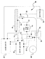
1 shows a schematic view of a welding system according to an exemplary embodiment of the invention;
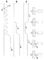
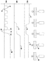
2 to 5 show a schematic view of a welding start operation according to various embodiments of the present invention.
DESCRIPTION OF THE PREFERRED EMBODIMENTS Hereinafter, exemplary embodiments of the present invention will be described with reference to the accompanying drawings. The described exemplary embodiments are intended to aid in the understanding of the present invention and are not intended to limit the scope of the invention in any way. Like reference numerals designate like elements throughout the drawings.
Figure 1 illustrates an
In an exemplary embodiment, the
As shown in FIG. 1, in some embodiments, a robot or
As described above, the beginning of the welding operation can be difficult because a spatter can be generated when the initial welding arc is generated. The following method employing the
As shown in Fig. 2, at the beginning of the operation, the
When the
As contact has been made, a first current (C1), which is lower than the arc welding current level, is provided through the wire (107) into the workpiece (W). That is, the current level C1 is such that a small arc can be generated between the
In some embodiments, when a contact is made, the
After the contact (as shown in step 3), the
This rebound voltage level V2 is detected by a
Further, after the detection of the rebound voltage V2, the
In
FIG. 3 illustrates another exemplary starting method similar to that shown in FIG. However, in this embodiment, the intermediate current level C2 is started after rebound (step 3) and before the start of the welding current CW. This intermediate current C2 is used to effect the
FIG. 4 shows another exemplary embodiment similar to FIG. However, in this embodiment, the wire feed rate is increased to the welding wire feed speed level SW after the rebound voltage V2, and / or the welding current CW is reached by the
Figure 5 illustrates another exemplary embodiment of the present invention. Again, many aspects of the starting method are similar to the other drawings. However, in this embodiment, the
In an exemplary embodiment of the invention, control is performed by
In the embodiments described above, the
While the present invention has been particularly shown and described with reference to exemplary embodiments thereof, the present invention is not limited to these embodiments. It will be understood by those skilled in the art that various changes in form and detail may be made therein without departing from the spirit and scope of the invention as defined by the following claims.
100: Welding system CW: Current
101: power source i: current
103: Feed mechanism S1: Speed
105: welding torch S1 ': speed
107: electrode / wire S2: speed
111: Ground part SR: Speed
113: wire SW: speed
115: Detection circuit t: Time
117: Lead wire T: Time
119: Lead wire T ': Time
121: Control wire T ": Time
123: Wire TR: Time
125: Device v: Voltage
127: control unit V1: voltage
201: Initial arc V2: Voltage
203: welding arc C1, C2: current
Vc: Contact level W: Workpiece
Claims (15)
Advancing an electrode (107) towards at least one workpiece (W) to be welded, the advance being pulse controlled between a first advancing speed and a second advancing speed, the first advancing speed being equal to the second advancing speed Higher, step;
Providing the sensing voltage V1, V2 to the electrode 107;
Detecting contact between the electrode (107) and the at least one workpiece (W);
Detecting separation of the electrode (107) from the at least one workpiece (W);
Stopping pulse control of the electrode (107) after detection of the separation;
Advancing the electrode (107) toward the at least one workpiece (W) at a first fixed speed after the interruption of the pulse control; And
Providing welding current (C1, C2, CW) to said electrode (107) to weld said at least one workpiece (W) after detection of said separation
≪ / RTI >
Providing a current after contacting the electrode (107) after detection of the contact, wherein the postcontact current is less than the welding current (CW).
And reversing the direction of the electrode (107) during an inversion period after detection of the contact.
A power supply source (101) for providing a sense voltage to the welding electrode (107);
A wire transfer mechanism (103) for advancing the welding electrode (107) toward at least one workpiece (W); And
A detection circuit (115) for detecting at least one of voltage and current between said welding electrode (107) and said at least one workpiece (W)
Wherein the wire transport mechanism (103) advances the welding electrode using a plurality of wire feed rate pulses, the pulse having a first wire feed rate during a first period and a second wire feed during a second period, Speed;
The detection circuit 115 detects contact between the welding electrode 107 and the at least one workpiece W and detects the separation of the welding electrode 107 and the at least one workpiece W;
After the detection circuit 115 detects the disconnection, the wire transport mechanism 103 advances the welding electrode 107 to the first fixed speed S1, S ', S2, SR, SW, Wherein the source (101) provides a welding current to the welding electrode (107).
Applications Claiming Priority (3)
| Application Number | Priority Date | Filing Date | Title |
|---|---|---|---|
| US13/411,471 | 2012-03-02 | ||
| US13/411,471 US9050676B2 (en) | 2012-03-02 | 2012-03-02 | Apparatus and method for starting arc welding process |
| PCT/IB2013/000314 WO2013128262A1 (en) | 2012-03-02 | 2013-02-26 | Apparatus for and method of starting arc welding process with pulsing wire before initiation of arcing |
Publications (1)
| Publication Number | Publication Date |
|---|---|
| KR20140132758A true KR20140132758A (en) | 2014-11-18 |
Family
ID=48142015
Family Applications (1)
| Application Number | Title | Priority Date | Filing Date |
|---|---|---|---|
| KR1020147027908A KR20140132758A (en) | 2012-03-02 | 2013-02-26 | Apparatus for and method of starting arc welding process with pulsing wire before initiation of arcing |
Country Status (6)
| Country | Link |
|---|---|
| US (1) | US9050676B2 (en) |
| JP (1) | JP5919399B2 (en) |
| KR (1) | KR20140132758A (en) |
| CN (1) | CN104271302A (en) |
| DE (1) | DE112013001259T5 (en) |
| WO (1) | WO2013128262A1 (en) |
Families Citing this family (5)
| Publication number | Priority date | Publication date | Assignee | Title |
|---|---|---|---|---|
| JP6320851B2 (en) * | 2014-06-06 | 2018-05-09 | 株式会社神戸製鋼所 | Arc start control method and welding apparatus for consumable electrode arc welding |
| US10384291B2 (en) * | 2015-01-30 | 2019-08-20 | Lincoln Global, Inc. | Weld ending process and system |
| EP3702084A1 (en) * | 2016-03-11 | 2020-09-02 | Daihen Corporation | Arc welding system and wire feeding device |
| US10500671B2 (en) * | 2017-04-06 | 2019-12-10 | Lincoln Global, Inc. | System and method for arc welding and wire manipulation control |
| US20200130094A1 (en) * | 2018-10-26 | 2020-04-30 | Illinois Tool Works Inc. | Systems and methods to start arc welding |
Family Cites Families (38)
| Publication number | Priority date | Publication date | Assignee | Title |
|---|---|---|---|---|
| GB1572847A (en) * | 1977-03-18 | 1980-08-06 | Rolls Royce | Plasma arc welding |
| US4288682A (en) * | 1979-11-28 | 1981-09-08 | Union Carbide Corporation | Welding system with reversible drive motor control |
| JPS5978778A (en) * | 1982-10-27 | 1984-05-07 | Hitachi Seiko Ltd | Arc starting method |
| JPS613673A (en) * | 1984-06-15 | 1986-01-09 | Hitachi Seiko Ltd | Control device for tig welding machine |
| US4717807A (en) * | 1986-12-11 | 1988-01-05 | The Lincoln Electric Company | Method and device for controlling a short circuiting type welding system |
| DE9013550U1 (en) * | 1990-09-26 | 1991-02-21 | Carl Cloos Schweisstechnik Gmbh, 6342 Haiger, De | |
| CN1051491C (en) * | 1997-12-12 | 2000-04-19 | 西安交通大学 | High-voltage pulse contact arc strike control method and control circuit for initial smelting electrode |
| US6034350A (en) * | 1998-04-01 | 2000-03-07 | Illinois Tool Works Inc. | Method and apparatus for initiating a welding arc using a background circuit |
| JP2002160059A (en) * | 2000-11-29 | 2002-06-04 | Babcock Hitachi Kk | Arc starting method and welding apparatus in consumable electrode arc welding |
| JP2002178146A (en) * | 2000-12-15 | 2002-06-25 | Daihen Corp | Arc start control method |
| US6531684B2 (en) * | 2001-06-19 | 2003-03-11 | Illinois Tool Works Inc. | Method and apparatus for welding and control |
| US6794608B2 (en) * | 2001-10-30 | 2004-09-21 | Tri Tool Inc. | Welding current control system and method |
| US6570131B1 (en) * | 2002-01-17 | 2003-05-27 | Lincoln Global, Inc. | Electric arc welder with arc starter |
| AUPS274002A0 (en) * | 2002-06-03 | 2002-06-20 | University Of Wollongong, The | Control method and system for metal arc welding |
| US6984806B2 (en) | 2002-07-23 | 2006-01-10 | Illinois Tool Works Inc. | Method and apparatus for retracting and advancing a welding wire |
| US7102099B2 (en) | 2002-07-23 | 2006-09-05 | Illinois Tool Works Inc. | Method and apparatus for feeding wire to a welding arc |
| US6963048B2 (en) | 2002-07-23 | 2005-11-08 | Illinois Tool Works Inc. | Method and apparatus for welding with mechanical arc control |
| US7165707B2 (en) | 2002-07-23 | 2007-01-23 | Illinois Tool Works Inc. | Method and apparatus for feeding wire to a welding arc |
| US6969823B2 (en) | 2002-07-23 | 2005-11-29 | Illinois Tool Works Inc. | Method and apparatus for controlling a welding system |
| AT413661B (en) | 2003-05-28 | 2006-04-15 | Fronius Int Gmbh | BUFFER DEVICE FOR A WELDING WIRE AND WELDING SYSTEM |
| AT412765B (en) | 2003-07-03 | 2005-07-25 | Fronius Int Gmbh | TORCH |
| JP2007508939A (en) | 2003-10-23 | 2007-04-12 | フロニウス・インテルナツィオナール・ゲゼルシャフト・ミット・ベシュレンクテル・ハフツング | Method for controlling welding process and welding apparatus for carrying out welding process |
| AT413660B (en) | 2004-01-27 | 2006-04-15 | Fronius Int Gmbh | DEVICE AND METHOD FOR TRANSPORTING A WIRE |
| AT413662B (en) | 2004-02-04 | 2006-04-15 | Fronius Int Gmbh | WELDING BURNER WITH A BURNER HOUSING |
| AT500653B1 (en) | 2004-06-09 | 2006-12-15 | Fronius Int Gmbh | WIRE CONVEYOR |
| US7323659B2 (en) | 2004-09-28 | 2008-01-29 | Illinois Tool Works Inc. | System and method of precise wire feed control in a welder |
| US20060070987A1 (en) * | 2004-09-30 | 2006-04-06 | Lincoln Global, Inc. | Monitoring device for welding wire supply |
| AT501489B1 (en) | 2005-02-25 | 2009-07-15 | Fronius Int Gmbh | METHOD FOR CONTROLLING AND / OR REGULATING A WELDING DEVICE AND WELDING DEVICE |
| US7335854B2 (en) | 2005-03-11 | 2008-02-26 | Illinois Tool Works Inc. | Method and system of determining wire feed speed |
| US7271365B2 (en) * | 2005-04-11 | 2007-09-18 | Lincoln Global, Inc. | System and method for pulse welding |
| AT501995B1 (en) | 2005-05-24 | 2009-07-15 | Fronius Int Gmbh | COLD METAL TRANSFER WELDING METHOD AND WELDING SYSTEM |
| JP4211793B2 (en) * | 2006-02-17 | 2009-01-21 | パナソニック株式会社 | Arc welding control method and arc welding apparatus |
| AT503469B1 (en) | 2006-04-12 | 2008-03-15 | Fronius Int Gmbh | WELDING |
| EP1941963B1 (en) * | 2006-10-27 | 2014-05-07 | Panasonic Corporation | Automatic welding device |
| FR2923167B1 (en) * | 2007-11-06 | 2010-03-26 | Air Liquide | ARC WELDING METHOD BY SHORT CIRCUIT WITH FUSIBLE ELECTRODE |
| EP2172296B1 (en) * | 2008-10-01 | 2011-12-21 | EWM Hightec Welding GmbH | Method and device for arc welding |
| JP5141826B2 (en) * | 2009-08-28 | 2013-02-13 | パナソニック株式会社 | Arc welding method and arc welding apparatus |
| WO2012032703A1 (en) * | 2010-09-10 | 2012-03-15 | パナソニック株式会社 | Arc welding control method |
-
2012
- 2012-03-02 US US13/411,471 patent/US9050676B2/en active Active
-
2013
- 2013-02-26 DE DE112013001259.6T patent/DE112013001259T5/en active Pending
- 2013-02-26 KR KR1020147027908A patent/KR20140132758A/en not_active Application Discontinuation
- 2013-02-26 WO PCT/IB2013/000314 patent/WO2013128262A1/en active Application Filing
- 2013-02-26 CN CN201380022824.2A patent/CN104271302A/en active Pending
- 2013-02-26 JP JP2014559305A patent/JP5919399B2/en not_active Expired - Fee Related
Also Published As
| Publication number | Publication date |
|---|---|
| JP5919399B2 (en) | 2016-05-18 |
| CN104271302A (en) | 2015-01-07 |
| US20130228559A1 (en) | 2013-09-05 |
| WO2013128262A1 (en) | 2013-09-06 |
| JP2015511891A (en) | 2015-04-23 |
| US9050676B2 (en) | 2015-06-09 |
| DE112013001259T5 (en) | 2014-12-11 |
Similar Documents
| Publication | Publication Date | Title |
|---|---|---|
| US10427236B2 (en) | Burner for a welding apparatus | |
| JP3204227U (en) | Welding termination process and system | |
| AT503469B1 (en) | WELDING | |
| CN107530813B (en) | Welding system and method with reduced energy welding | |
| US9018563B2 (en) | Consumable-electrode gas-shield arc welding method and consumable-electrode gas-shield arc welding system | |
| US10046410B2 (en) | Apparatus and method for modulating heat input during welding | |
| US20120074112A1 (en) | Arc welding method reducing occurrences of spatter at time of arc start | |
| KR20140132758A (en) | Apparatus for and method of starting arc welding process with pulsing wire before initiation of arcing | |
| JP2016506873A (en) | Welding wire preheating system and method | |
| EP3246122A1 (en) | Method and system to use combination filler wire feed and high intensity energy source for welding and arc suppression of a variable polarity hot-wire | |
| CN105880799B (en) | Method and system for increasing heat input to a weld during short circuit arc welding | |
| JPWO2005120758A1 (en) | Robot welding control device and control method | |
| US11969834B2 (en) | Real time resistance monitoring of an arc welding circuit | |
| JP6145694B2 (en) | Arc welding control method and arc welding apparatus | |
| KR101676911B1 (en) | Arc welding apparatus, arc welding system, and arc welding method | |
| US20160250708A1 (en) | Arc welding method, arc welding apparatus, and arc welding controller | |
| JP5545996B2 (en) | Constriction detection control method for consumable electrode arc welding | |
| US11478871B2 (en) | Welding apparatus and welding method | |
| EP3398707A1 (en) | Welding power supply with adjustable resistance | |
| EP3450075A1 (en) | Welding power supply with a controller for identification of remote switch operation | |
| JP4211724B2 (en) | Arc welding control method and arc welding apparatus | |
| US20220055136A1 (en) | Arc welding method and arc welding device | |
| CN111745264B (en) | Real-time resistance monitoring of arc welding circuits | |
| EP4180163A1 (en) | Welding or additive manufacturing system with discontinuous electrode feeding | |
| JP2023172539A (en) | Arc welding method and arc welding device |
Legal Events
| Date | Code | Title | Description |
|---|---|---|---|
| WITN | Withdrawal due to no request for examination |