KR20140131380A - Piston retention apparatus and method - Google Patents
Piston retention apparatus and method Download PDFInfo
- Publication number
- KR20140131380A KR20140131380A KR1020147027343A KR20147027343A KR20140131380A KR 20140131380 A KR20140131380 A KR 20140131380A KR 1020147027343 A KR1020147027343 A KR 1020147027343A KR 20147027343 A KR20147027343 A KR 20147027343A KR 20140131380 A KR20140131380 A KR 20140131380A
- Authority
- KR
- South Korea
- Prior art keywords
- piston
- rod
- threaded
- bore
- rod member
- Prior art date
Links
Images

Classifications
-
- F—MECHANICAL ENGINEERING; LIGHTING; HEATING; WEAPONS; BLASTING
- F16—ENGINEERING ELEMENTS AND UNITS; GENERAL MEASURES FOR PRODUCING AND MAINTAINING EFFECTIVE FUNCTIONING OF MACHINES OR INSTALLATIONS; THERMAL INSULATION IN GENERAL
- F16J—PISTONS; CYLINDERS; SEALINGS
- F16J1/00—Pistons; Trunk pistons; Plungers
- F16J1/005—Pistons; Trunk pistons; Plungers obtained by assembling several pieces
-
- F—MECHANICAL ENGINEERING; LIGHTING; HEATING; WEAPONS; BLASTING
- F16—ENGINEERING ELEMENTS AND UNITS; GENERAL MEASURES FOR PRODUCING AND MAINTAINING EFFECTIVE FUNCTIONING OF MACHINES OR INSTALLATIONS; THERMAL INSULATION IN GENERAL
- F16J—PISTONS; CYLINDERS; SEALINGS
- F16J1/00—Pistons; Trunk pistons; Plungers
- F16J1/08—Constructional features providing for lubrication
-
- Y—GENERAL TAGGING OF NEW TECHNOLOGICAL DEVELOPMENTS; GENERAL TAGGING OF CROSS-SECTIONAL TECHNOLOGIES SPANNING OVER SEVERAL SECTIONS OF THE IPC; TECHNICAL SUBJECTS COVERED BY FORMER USPC CROSS-REFERENCE ART COLLECTIONS [XRACs] AND DIGESTS
- Y10—TECHNICAL SUBJECTS COVERED BY FORMER USPC
- Y10T—TECHNICAL SUBJECTS COVERED BY FORMER US CLASSIFICATION
- Y10T29/00—Metal working
- Y10T29/49—Method of mechanical manufacture
- Y10T29/49229—Prime mover or fluid pump making
- Y10T29/49249—Piston making
- Y10T29/49256—Piston making with assembly or composite article making
Abstract
실린더 조립체(10)를 형성하기 위해 피스톤(18)을 로드(22)에 결합시키기 위한 장치 및 방법이 제공된다. 피스톤은 이를 통해 연장되며 로드의 제1 나사 영역(63)에 결합되는 탭 보어(30)를 구비한다. 로드 단부(29)는 피스톤 부재(18)를 지나 연장되며, 유지 부재(26)의 탭 보어(83)에 결합되는 제2 나사 영역(89)을 포함한다. 피스톤 부재는 예컨대 약 1000Nm 이하의 낮은 토크로 로드 부재에 결합된다. 피스톤 보어의 나사 세그먼트 및 로드 부재의 제1 부분의 제1 나사 영역 각각의 나사 설계는 0.125피치보다 큰 루트 반경으로 또는 MJ 등급 나사로 형성될 수 있다. 유지 부재는 로드 단부와의 마찰식 체결을 위해 서로로부터 오프셋되는 고정나사들(96)을 포함할 수 있다. 로드와 피스톤 사이의 나사 피치는 로드와 유지 부재 사이의 나사 피치보다 거칠 수 있다. 로드와 피스톤 사이의 밀봉 영역 및 경계면은 나사 결합부(67)보다 피스톤 부재의 로드 단부측(31)에 더 가깝게 배치될 수 있다.An apparatus and method for coupling a piston (18) to a rod (22) to form a cylinder assembly (10) are provided. The piston has a tab bore (30) extending therethrough and coupled to the first threaded region (63) of the rod. The rod end 29 extends beyond the piston member 18 and includes a second threaded region 89 that engages the tab bore 83 of the retaining member 26. The piston member is coupled to the rod member with a low torque, for example less than about 1000 Nm. The threaded design of each of the threaded segments of the piston bore and the first threaded region of the first portion of the rod member may be formed with a root radius greater than 0.125 pitch or with a MJ grade thread. The retaining member may include set screws (96) that are offset from each other for a frictional engagement with the rod end. The thread pitch between the rod and the piston may be rougher than the thread pitch between the rod and the retaining member. The sealing area and interface between the rod and the piston may be disposed closer to the rod end side 31 of the piston member than the threaded engagement portion 67. [
Description
본 개시는 전반적으로 피스톤 및 로드 조립체에 관한 것으로, 특히 피스톤 및 로드를 함께 결합시키기 위한 장치 및 방법에 관한 것이다.This disclosure relates generally to pistons and rod assemblies, and more particularly to apparatus and methods for coupling pistons and rods together.
유압 실린더 장치는 통상적으로 피스톤 및 로드 조립체를 형성하기 위해 로드 부재에 결합되는 피스톤 부재를 포함한다. 과거에는 피스톤 부재를 로드 부재에 결합시키기 위해 다양한 결합 장치들이 사용되었다.Hydraulic cylinder devices typically include a piston member that is coupled to a rod member to form a piston and a rod assembly. In the past, various coupling devices have been used to couple the piston member to the rod member.
예컨대, 표준 피스톤 및 로드 조립체에서, 직경이 감소하는 나사 단부를 구비한 로드 부재가 제공된다. 피스톤 부재는 로드 부재 단부 위에 수용되며, 로드 부재 단부에 인접한 비-나사 영역에 미끄럼 가능하게 체결되도록 제공된다. 피스톤 부재를 로드 부재 상에 유지하기 위해, 피스톤 너트가 로드 부재 단부에 나사식으로(threadably) 체결될 수 있다.For example, in a standard piston and rod assembly, a rod member is provided having a threaded end with reduced diameter. A piston member is received above the rod member end and is provided to be slidably engaged in a non-threaded region adjacent the rod member end. To hold the piston member on the rod member, a piston nut may be threadably fastened to the rod member end.
다른 예로, 피스톤 및 로드 조립체(5)가 도 1에 도시되어 있다. 여기서, 피스톤 부재(6) 자체는 약 0.125피치의 루트 반경, 또는 피치가 3일 때 0.375㎜의 루트 반경을 가진 표준 M-등급 나사를 이용하여 로드 단부(7) 위로 나사결합된다. 또한, 피스톤 부재와 로드 부재 사이의 상대 회전을 방지하기 위해, 한 쌍의 오프셋 sinuLOCTM 고정나사들이 로드 단부에 체결되도록 피스톤 부재의 바디를 관통하여 사용된다. 도 1의 조립체는 백호 로더(backhoe loader)를 요구하는 응용에서 발견되는 것과 같이, 낮은 압력, 낮은 작동 주기, 및/또는 낮은 수명 주기 응용과 같은 더 가벼운 하중을 위해 만족스럽게 작동하지만, 더 무거운 하중을 처리할 수 있는 조립체에 대한 필요성이 남아있다.As another example, a piston and
국내 특허출원 공개번호 KR 20100094186A에는, 다른 피스톤 및 로드 조립체가 기재되어 있다. 공개문헌은 피스톤의 암나사 보어에 정합되는 수나사 단부를 구비한 로드를 포함하는 피스톤 및 로드 조립체를 개시한다. 피스톤이 로드로부터 풀리는 것을 방지하기 위해, 피스톤 너트가 또한 피스톤과 접촉하여 로드 단부에 나사식으로 체결된다. 하나 이상의 고정나사가 피스톤 너트의 내주를 통해 반경방향으로 연장되는 대응하는 반경방향 개구들을 통해 삽입되어, 로드 단부에 체결된다. 예컨대, 2개의 고정나사들이 로드의 중심에 대해 편심 배치된다. 또한, 로드 단부보다 헤드 단부에 더 가까운, 로드와 피스톤 사이의 단차진 경계면의 위치는 이 경계면에서 응력 집중부(stress riser)의 발생 및 그에 따른 조인트 고장의 가능성을 증가시킨다는 점에서 바람직하지 않다.In the domestic patent application publication number KR 20100094186A another piston and rod assembly is described. The publication discloses a piston and rod assembly comprising a rod having a male thread end that mates with the female thread bore of the piston. To prevent the piston from unwinding from the rod, a piston nut is also threaded into the rod end in contact with the piston. One or more set screws are inserted through corresponding radial openings which extend radially through the inner periphery of the piston nut and are fastened to the rod end. For example, two set screws are eccentrically disposed about the center of the rod. Also, the position of the stepped interface between the rod and the piston, closer to the head end than the rod end, is undesirable in that it increases the likelihood of stress risers occurring and hence joint failure.
전술한 바와 같이, 종래의 피스톤 및 로드 조립체는 피스톤 부재 및 로드 부재를 함께 결합시키기 위해 로드 단부에 나사결합되는 너트를 구비한, 미끄럼 가능하게 체결된 로드 및 피스톤 조인트 사이의 체결에 상당히 의존할 수 있다. 그러나, 이러한 구성을 위해, 로드 단부에 너트를 조이며, 피스톤 및 로드 조립체 사이에 유지 조인트를 형성하기 위해, 예컨대 13,000 내지 20,000Nm과 같은 높은 토크가 사용된다. 높은 토크 적용의 결과, 나사산들에 인장력이 프리로드(pre-loaded)되어, 통상 너트와 로드 단부 사이의 첫 3개의 나사산들만이 대부분의 하중을 지탱하고, 남은 나사산들은 충분히 사용되지 않게 된다. 그러므로, 프리로드와 함께 로드 단부 및 헤드 단부 양 방향으로부터의 축방향 하중의 적용은 나사산들에 더 큰 총 응력 범위를 제공하여, 나사산들은 피로 및 풀림에 매우 취약하게 된다. 너트를 로드 단부에 결합시키기 위해, 로드 단부는 종종 유효 단면 감소 영역으로 가공되어, 더 작은 단면 영역이 더 높은 하중을 지탱하게 된다. 그 결과로, 로드 단부는 더 높은 강도를 위한 방식으로 가공되어야 하므로(예컨대, 더 높은 강도의 재료로 제조되고/제조되거나 열처리됨), 전체 제조 비용을 증가시키고/증가시키거나, 응력 집중자의 가능성을 증가시킨다. 또한, 높은 토크로 결합된 나사 조인트의 피로는 더 낮은 토크 적용에 비해 상당히 감소한다. 따라서, 이러한 의존을 감소시키거나 제거하면, 종래의 결합 배열이 제공한 것보다 더 강하거나, 더 실용적 또는 경제적인 구조의 구성을 용이하게 할 것이다.As discussed above, conventional piston and rod assemblies can be highly dependent on fastening between the slidably engaged rod and piston joint, with a nut threaded into the rod end to couple the piston member and the rod member together have. However, for this configuration, high torque is used, such as 13,000 to 20,000 Nm, for example, to tighten the nut to the rod end and form a retaining joint between the piston and the rod assembly. As a result of the high torque application, tensile forces are pre-loaded on the threads so that only the first three threads between the nut and the rod end normally bear most of the load and the remaining threads are not fully used. Therefore, the application of axial loads from both the rod end and the head end together with the preload provides a larger total stress range for the threads, making the threads very vulnerable to fatigue and unwinding. In order to engage the nut with the rod end, the rod end is often machined into an effective section reduction area such that the smaller section area sustains the higher load. As a result, the rod ends must be machined in a manner for higher strength (e.g., manufactured / manufactured or heat treated with a higher strength material), thereby increasing / increasing the overall manufacturing cost, . Also, the fatigue of threaded joints coupled with high torque is significantly reduced compared to lower torque applications. Thus, reducing or eliminating this dependency will facilitate construction of structures that are stronger, more practical, or economical than those provided by conventional coupling arrangements.
본원에 설명된 구현예들은 종래의 피스톤 및 로드 조립체와 연관된 단점들 중 하나 이상을 극복하기 위한 것이다.The implementations described herein are intended to overcome one or more of the disadvantages associated with conventional piston and rod assemblies.
일 실시예에서, 구동 장치와 함께 사용되는 피스톤 및 로드 조립체가 제공된다. 조립체는 피스톤 부재, 로드 부재, 및 유지 부재를 포함할 수 있다. 피스톤 부재는 제1 단부와 제2 단부 사이에 연장되는 피스톤 보어를 구비할 수 있다. 피스톤 보어는 나사 세그먼트일 수 있다. 로드 부재는 피스톤 보어의 나사 세그먼트에 나사식으로 체결될 제1 나사 영역을 구비할 수 있다. 로드 부재의 단부 영역이 피스톤 부재의 제2 단부를 지나 연장될 수 있다. 제2 나사 영역이 단부 영역을 따라 제공될 수 있다. 유지 부재는 내부에 연장되는 유지 보어를 구비할 수 있다. 유지 보어는 로드 부재의 제2 나사 영역에 나사식으로 체결될 나사 부분을 구비할 수 있다. 나사 세그먼트 및 제1 나사 영역은 수나사의 골밑에서 0.125피치(P)보다 큰 루트 반경으로, 또는 수나사의 골밑에서 약 0.18042P 내지 약 0.15011P 범위의 루트 반경으로, 또는 대안적으로 MJ 등급 나사에 따라 형성될 수 있다.In one embodiment, a piston and rod assembly for use with a drive device is provided. The assembly may include a piston member, a rod member, and a retaining member. The piston member may have a piston bore extending between the first end and the second end. The piston bore may be a thread segment. The rod member may have a first threaded region to be threadably fastened to the threaded segment of the piston bore. An end region of the rod member may extend beyond the second end of the piston member. A second threaded region may be provided along the end region. The retaining member may have retaining bores extending therein. The retaining bore may have a threaded portion to be threadably fastened to the second threaded region of the rod member. The thread segment and the first threaded region may be provided with a root radius greater than 0.125 pitch (P) below the base of the male screw, or a root radius ranging from about 0.18042P to about 0.15011P below the base of the male thread, or alternatively, .
다른 실시예에서, 피스톤 부재는 약 1000Nm 이하의 낮은 토크로 로드 부재에 결합될 수 있다. 피스톤 보어는 내부 안착부를 포함할 수 있고, 로드 부재는 외부 견부를 포함할 수 있다. 내부 안착부 및 외부 견부는 경계면을 형성하기 위해 서로 체결될 수 있다. 피스톤 보어는 밀봉 부재를 수용하기 위해 내부 안착부에 인접하게 배치되는 내부 밀봉 홈을 포함할 수 있다. 경계면 및 내부 밀봉 홈은 나사 세그먼트보다 피스톤 부재의 제1 단부 또는 로드 단부측에 더 가깝게 배치될 수 있다. 또 다른 실시예에서, 유지 부재는 횡축에 대해 서로 오프셋 관계인 한 쌍의 고정나사 보어들 및 그 안에 나사식으로 체결되는 대응하는 고정나사들을 포함할 수 있다. 고정나사들의 선단부들은 로드 부재 단부 영역의 요홈 랜딩부에 체결될 수 있다.In another embodiment, the piston member can be coupled to the rod member with a low torque of about 1000 Nm or less. The piston bore may include an internal seating portion, and the rod member may include an external shoulder. The inner seating portion and the outer shoulder can be fastened to each other to form an interface. The piston bore may include an internal sealing groove disposed adjacent the internal seating for receiving the sealing member. The interface and the inner sealing groove may be disposed closer to the first end or rod end side of the piston member than the thread segment. In yet another embodiment, the retaining member may include a pair of retaining screw bores that are offset relative to each other about the transverse axis and corresponding retaining screws threadably fastened thereto. The tip portions of the fixing screws can be fastened to the concave landing portion of the rod member end region.
일 실시예에서, 피스톤 보어를 구비한 피스톤 부재를 로드 부재에 결합시키는 방법이 제공된다. 방법은 하기 단계들 중 하나 이상을 포함할 수 있다. 일 단계는 피스톤 보어의 내부 안착부 및 로드 부재의 외부 견부가 서로 체결될 때까지 기결정된 토크로 로드 부재의 제1 부분을 피스톤 보어에 나사식으로 체결하는 단계를 포함할 수 있다. 피스톤 보어의 나사 세그먼트 및 로드 부재의 제1 부분의 제1 나사 영역 각각의 수나사는 피치를 가지며, 0.125피치보다 큰 루트 반경으로 형성된다. 토크는 약 1000Nm 이하의 임의의 토크일 수 있다. 다른 단계는 로드 부재의 제2 부분을 유지 부재의 유지 보어에 나사식으로 체결하는 단계를 포함할 수 있다. 또 다른 단계는 고정나사의 선단부가 로드 부재에 체결되도록, 적어도 하나의 고정나사를 유지 부재에 형성된 대응하는 고정나사 보어를 통해 나사식으로 체결하는 단계를 포함할 수 있다.In one embodiment, a method of coupling a piston member with a piston bore to a rod member is provided. The method may include one or more of the following steps. One step may include screwing the first portion of the rod member to the piston bore with a predetermined torque until the internal seating of the piston bore and the external shoulder of the rod member are engaged with each other. The male thread of each of the threaded segments of the piston bore and the first threaded region of the first portion of the rod member has a pitch and is formed with a root radius greater than 0.125 pitch. The torque may be any torque of about 1000 Nm or less. Another step may include screwing the second portion of the rod member to the retaining bore of the retaining member. Another step may include threading the at least one set screw through a corresponding set screw bore formed in the retaining member such that the tip of the set screw is fastened to the rod member.
도 1은 피스톤 및 로드 조립체를 도시한다.
도 2는 피스톤 및 로드 조립체를 구비한 실린더 조립체를 도시한다.
도 3은 고정나사 보어들을 도시한 유지 부재의 횡단면도이다.
도면이 본 개시의 예시적인 구현예들 또는 특징들을 도시하고 있지만, 도면은 반드시 일정한 비율로 나타낸 것은 아니며, 소정의 특징들은 본 개시를 더 잘 예시하고 설명하기 위해 과장된 것일 수 있다. 본원에 기술된 예시들은 본 개시의 예시적인 구현예들 또는 특징들을 설명하며, 이러한 예시들은 어떤 방식으로든 본 발명의 범위를 제한하는 것으로 해석되지 않아야 한다.Figure 1 shows a piston and rod assembly.
Figure 2 shows a cylinder assembly with a piston and rod assembly.
Figure 3 is a cross-sectional view of the retaining member showing the fixing screw bores.
Although the drawings illustrate exemplary implementations or features of the present disclosure, the drawings are not necessarily to scale, and certain features may be exaggerated to better illustrate and describe the present disclosure. The examples set forth herein illustrate exemplary implementations or features of the present disclosure, and such examples should not be construed as limiting the scope of the invention in any way.
이하에서는, 본 개시의 구현예들을 상세히 참조할 것이며, 그 실시예들이 첨부 도면에 도시되어 있다. 가능하다면, 도면에 걸쳐, 동일한 도면부호들이 동일 또는 유사한 구성요소들을 지시하기 위해 사용될 것이다.In the following, reference will be made in detail to implementations of the present disclosure, examples of which are illustrated in the accompanying drawings. Wherever possible, the same reference numbers will be used throughout the drawings to designate the same or similar elements.
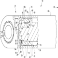
도 2를 참조하면, 실린더 조립체(10)는 피스톤 및 로드 조립체(14)를 포함할 수 있다. 피스톤 및 로드 조립체(14)는 피스톤 부재(18), 바람직하게는 원통형의 로드 부재(22), 및 유지 부재(26)를 포함할 수 있다. 실린더 조립체(10)는 헤드 단부(27) 및 화살표 29로 나타낸 로드 단부를 구비할 수 있다.Referring to FIG. 2, the
피스톤 부재(18)는 내부에 종방향으로 형성되는 피스톤 보어(30)를 구비한 링 형상의 요소일 수 있고, 이 피스톤 보어는 피스톤 부재(18)의 제1 단부(31)와 제2 단부(33) 사이에 연장된다. 제2 단부(33)는 제1 단부(31)보다 실린더 조립체의 헤드 단부(27)에 더 가까울 수 있다. 피스톤 보어(30)는 실질적으로 원통형 형상일 수 있으며, 피스톤 부재(18)를 완전히 관통하여 연장될 수 있다. 하나 이상의 외부 밀봉 홈(42)이 피스톤 부재(18)의 외주의 주위에 형성될 수 있다. 밀봉 부재(미도시) 또는 마모 밴드가 실린더의 실린더 바디(62)의 내표면(58)에 밀봉식으로(sealably) 체결되도록 홈(42)들 내에 안착될 수 있다. 피스톤 부재(18)의 외경은 실린더의 내경보다 약간 더 작을 수 있다.The
피스톤 부재(18)는 로드 부재(22)에 나사식으로 체결될 수 있다. 후술하는 바와 같이, 피스톤 부재(18)를 로드 부재(22)에 나사식으로 체결하기 위해 낮은 토크가 사용될 수 있다. 일 실시예에서, 로드 부재(18)의 제1 외부 세그먼트(63)는 제1 나사 체결부(67)를 한정하기 위해 피스톤 보어(30)를 한정하는 벽의 내부 나사 세그먼트(65)와 대응하여 나사결합될 수 있다. 로드 부재(22) 및 피스톤 보어(30)의 경계면 부분들은 특정한 응용을 위한 효과적인 결합을 위해 적어도 실질적으로 동일한 치수(예컨대, 직경)를 가질 수 있음을 이해할 수 있다.The
제1 내부 밀봉 홈(66)이 피스톤 보어(30)를 한정하는 벽의 벽 세그먼트 내에 배치될 수 있다. O링과 같은 밀봉 부재(70)가 로드 부재(22)의 외표면에 밀봉식으로 체결되도록 그 안에 안착될 수 있다. 밀봉 부재(70)는 가압 유체가 로드 부재(22)와 피스톤 보어(30) 사이에서 실린더 조립체(10)의 유체 챔버(74)의 방향 또는 반대편 유체 챔버(88)의 방향으로 통과하는 것을 방지할 수 있다.A first
외부 견부(75)가 로드 부재(22)의 외주의 주위에 형성될 수 있다. 예컨대, 외부 견부(75)는 로드 부재(22)의 제1 외경으로부터 로드 부재(22)의 더 작은 제2 직경으로의 제1 전이부에 의해 형성될 수 있다. 로드 부재의 제1 외경 영역은 비나사 영역일 수 있는 반면, 제2 외경 영역은 나사산이 형성될 수 있는 로드 부재의 제1 외부 세그먼트(63)에 대응할 수 있다. 피스톤 부재(18)는 외부 견부(75)에 체결되도록 피스톤 보어(30)의 내주의 주위에 형성되는 내부 안착부(76)를 포함할 수 있다. 예컨대, 내부 안착부(76)는 피스톤 부재(18)의 제1 외경으로부터 피스톤 부재(18)의 더 작은 제2 직경으로의 전이부에 의해 형성될 수 있다. 피스톤 부재(18)의 제1 외경 영역은 비나사 영역일 수 있는 반면, 제2 외경 영역은 피스톤 부재의 내부 나사 세그먼트(65)에 대응할 수 있다. 외부 견부(75) 및 내부 안착부(76)는 개선된 원추형 경계면을 위해 각각 테이퍼질 수 있다.An
일 실시예에서, 외부 견부(75) 및 내부 안착부(76) 경계면은 경계면 조인트에서 응력 집중 가능성을 감소시키기 위해 피스톤 부재(18)의 제2 단부(33)보다 제1 단부(31)에 더 가깝게 배치될 수 있다. 다른 실시예에서, 외부 견부(75) 및 내부 안착부(76) 경계면이 헤드 단부(27)의 방향으로부터의 축방향 하중을 지지하여, 로드 부재와 피스톤 부재 사이의 나사 영역이 견뎌야 할 축방향 하중의 양을 감소시킬 수 있도록, 이러한 경계면은 로드 단부(29)를 향한 방향에 있을 수 있다. 따라서, 개선된 성능을 위해, 이러한 경계면은 나사 영역의 로드 단부(즉, 우측)에 있을 수 있다.In one embodiment, the
제1 내부 밀봉 홈(66) 및 밀봉 부재(70)에 의해 형성된 밀봉 영역과 외부 견부(75)와 내부 안착부(76) 간의 경계면 사이의 상대 위치는 서로 인접할 수 있다. 일 실시예에서, 개선된 조립을 위해, 이러한 밀봉 영역은 경계면의 로드 단부(즉, 우측)에 있을 수 있다. 이는 밀봉 부재(70)의 압축 이전에 로드 부재와 피스톤 부재 사이의 원하는 나사 체결을 가능하게 할 수 있다. 밀봉 영역이 경계면에 비해 로드 단부에 더 가까울수록, 밀봉 부재(70)의 더 높은 핀치 또는 커팅 가능성과 함께, 조립이 더 어려워질 수 있다.The relative positions between the sealing region formed by the first
로드 부재(22)의 일부, 예컨대 제1 외경 세그먼트는 피스톤 보어(30) 내에 수용될 수 있다. 로드 부재(22)의 단부(82)는 피스톤 부재(18)의 제2 단부(33)를 완전히 지나 연장될 수 있다. 로드 부재 단부(82)는 유지 부재(26)에 결합되도록 구성되고 배치될 수 있다.A portion of the
유지 부재(26)는 내부에 종방향으로 형성되는 관통 보어(83)를 구비한 링 형상의 요소일 수 있고, 이 관통 보어는 유지 부재(26)의 제1 단부(85)와 제2 단부(86) 사이에 연장된다. 제2 단부(86)는 제1 단부(85)보다 실린더 조립체의 헤드 단부(27)에 더 가까울 수 있다. 관통 보어(83)는 실질적으로 원통형 형상일 수 있으며, 유지 부재(26)를 완전히 관통하여 연장될 수 있다.The retaining
유지 부재(26)는 로드 부재(22)와 나사식으로 체결될 수 있다. 일 실시예에서, 로드 부재 단부(82)에 대응하는 로드 부재(18)의 제2 외부 세그먼트(89)는 제2 나사 체결부(87)를 한정하기 위해 관통 보어(83)의 내부 나사 세그먼트(90)와 대응하여 나사결합될 수 있다. 관통 보어(83) 및 로드 부재(22)의 일부는 특정한 응용을 위한 효과적인 결합을 위해 적어도 실질적으로 동일한 치수(예컨대, 직경)를 가질 수 있음을 이해할 수 있다. 제2 외부 세그먼트(89)는 비나사 상태로 남아있는 랜딩부(89A)에 의해 분리될 수 있다. 랜딩부(89A)는 제2 외부 세그먼트(89)의 주변 인접 나사 부분에 대해 요홈을 이룰 수 있다.The holding
일 실시예에서, 유지 부재(26)는 강철 등과 같은 실질적으로 경질의 재료로 형성될 수 있고, 피스톤 및 로드 조립체(14)의 작동 중에 겪을 가능성이 높은 최대 응력의 적어도 1.3배의 인장 강도를 가질 수 있다. 유지 부재(26)의 외표면은 원하는 인장 강도를 얻기 위해 열처리될 수 있다.In one embodiment, the retaining
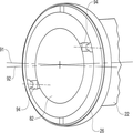
도 3은 로드 부재 단부(82)에 결합되는 유지 부재(26)의 일 실시예의 횡단면도를 도시한다. 여기서, 유지 부재(26)는 축방향 중앙축(91)을 중심으로 배치된 것으로 도시된다. 횡축(92)이 유지 부재(26)의 절반 섹션들을 한정하기 위해 축방향 중앙축(91)을 통해 및 이를 가로질러 연장된다. 하나 이상의 고정나사 보어(94)가 유지 부재(26)의 외주로부터 내주로 연장되도록 형성될 수 있고, 그에 따라 고정나사 보어는 유지 부재(26)의 관통 보어(83)와 유체 소통될 수 있다. 고정나사 보어(94)는 암나사로 형성될 수 있고, 도 2에 도시된 바와 같은 고정나사(96)를 수용할 수 있다. 조여질 때, 고정나사 선단부는 유지 부재(26)의 풀림을 방지하기 위해 로드 부재 단부(82)의 외주에 체결될 수 있다. 일 실시예에서, 고정나사 선단부는 랜딩부(89A)에 체결될 수 있다. 도 3에 따르면, 한 쌍의 고정나사 보어들(94)이 형성될 수 있을 때, 이 보어들은 횡축(92)을 따라 또는 횡축(92)에 실질적으로 평행할 수 있는 축을 중심으로 형성될 수 있거나, 오프셋 위치에 있을 수도 있다. 일 실시예에서, (각각 하나의 고정나사를 수용하기 위한) 2개의 고정나사 보어들이 횡축(92)으로부터 각각 오프셋될 수 있고, 바람직하게는 실질적으로 동일한 간격으로 오프셋될 수 있다. 여기서, 조여질 때, 서로 오프셋 관계인 한 쌍의 고정나사들은 유지 부재(26)가 로드 부재 단부(82)로부터 풀리는 것을 방지하는 데 도움이 될 수 있다. 개선된 체결을 위해, 즉 물러남(backing out)을 방지하기 위해, 고정나사(96)의 고정나사 나사부의 일부가 sinuLOCTM 나사와 같은 파형부(wavy portion)로 형성될 수 있다. 당업자들은 하나의 고정나사가 횡축을 따라 또는 횡축으로부터 오프셋되어 또는 유지 부재를 따른 임의의 위치를 따라 제공될 수 있다는 것과, 3개 이상의 고정나사들이 유지 부재를 따른 임의의 위치를 따라 제공될 수 있다는 것을 이해할 수 있다.3 shows a cross-sectional view of one embodiment of a retaining
일 실시예에서, 제1 나사 체결부(67)의 나사 피치는 제2 나사 체결부(87)의 나사 피치와 상이할 수 있다. 다른 실시예에서, 제1 나사 체결부(67)의 나사 피치는 제2 나사 체결부(87)의 나사 피치보다 더 거칠 수 있다.In one embodiment, the thread pitch of the first threaded
제1 및 제2 나사 체결부(67, 87) 양자의 나사 설계는 당해 기술분야에 알려진 임의의 종래의 나사일 수 있다. 나사 설계의 외관은 수 개의 구별되는 특징부들을 포함한다. 즉, 나사 설계는 플랭크 또는 나사면, 하나의 나사산의 2개의 플랭크들을 연결하는 산봉우리(crest) 또는 상면, 2개의 인접한 플랭크들의 플랭크들을 연결하는 골밑 또는 하면, 및 통상 TPI(threads per inch)로 표현되는, 축에 평행하게 측정된 인접한 나사산들의 2개의 대응점들 사이의 간격인 피치(P)를 포함한다. 수나사의 골지름은 수나사의 골밑에 접촉하는 가상 원통체의 직경일 수 있고, 암나사의 바깥지름은 암나사의 산봉우리에 접촉하는 가상 원통체의 직경일 수 있다.The thread design of both the first and second
약 0.125P보다 큰 루트 반경을 가진 나사 설계가 종래의 M 등급 나사에 비해 피로 수명을 개선할 수 있다는 것이 밝혀졌다. 게다가, 이러한 나사 설계를 가진 로드 단부는, 더 큰 응력 집중 위험에 기여하는, 더 높은 강도를 위한 방식으로 가공될(예컨대, 더 높은 강도의 재료로 제조되고/제조되거나 열처리될) 필요가 없다. 일 실시예에서, 나사 설계는 수나사의 골밑에서 약 0.15P 내지 약 0.18P(0.18042P 내지 0.15011P) 범위의 루트 반경을 포함할 수 있다. 0.18042P보다 큰 루트 반경은 피로 수명을 더 개선할 수 있다. 이를 위해, 수나사 및 암나사 양자의 골지름은 수나사 최대 루트 반경을 수용하기 위해 0.5625H의 기본 나사 높이를 제공하도록 증가될 수 있다. 나사 설계는 ISO 표준 5855에 따른 항공우주 미터규격 나사(MJ)일 수 있다. 일 실시예에서, 각각의 나사 설계는 MJ 등급 나사일 수 있다.It has been found that a threaded design with a root radius greater than about 0.125 P can improve fatigue life compared to conventional M grade threads. In addition, the rod ends with such a threaded design need not be machined (e.g., made / manufactured or heat treated) with a higher strength material, contributing to a greater stress concentration risk. In one embodiment, the threaded design may include a root radius in the range of about 0.15P to about 0.18P (0.18042P to 0.15011P) below the base of the male screw. Root radii greater than 0.18042P can further improve fatigue life. To this end, the bore diameters of both male and female threads can be increased to provide a base screw height of 0.5625H to accommodate the maximum root radius of the male thread. The threaded design may be an aerospace metric thread (MJ) according to ISO standard 5855. In one embodiment, each thread design may be an MJ grade thread.
산업상 이용 가능성Industrial availability
본원에 설명된 구현예들은 피스톤 및 로드 조립체(14)를 위한 견고한 결합 메커니즘 및 방법을 제공하면서, 비교적 쉬운 조립 과정을 용이하게 할 것이다. 또한, 본원에 설명된 구현예들은 결합 메커니즘의 내구성, 제조성, 및 유용성을 개선할 수 있다.The embodiments described herein will facilitate a relatively easy assembly process, while providing a robust coupling mechanism and method for the piston and
조립 중에, 외부 견부(75)가 피스톤 내부 안착부(76)에 체결되어 원추형 경계면을 형성할 수 있을 때까지, 로드 부재(22)가 피스톤 부재(18)의 피스톤 보어(30) 내에 나사식으로 수용될 수 있다. 로드 부재 단부(82)는 피스톤 부재(18)의 외부에서 연장될 수 있다. 피스톤 부재를 로드 부재에 결합시키기 위해 적용되는 토크는 임의의 토크일 수 있다. 일 실시예에서, 높은 토크를 수반하는 문제점을 극복하기 위해, 낮은 토크는 약 1000Nm 이하, 약 400 내지 약 500Nm의 범위, 또는 바람직하게는 450Nm일 수 있다. 낮은 토크 결합은 나사 경계면을 따른 힘의 개선된 분포를 위해 실질적으로 모든 나사 영역들을 최대한 이용하도록, 로드 부재에 대한 피스톤 부재의 약간의 이동을 가능하게 한다. 밀봉 부재는 나사식 체결 이전에 홈 내에 있을 수 있다. 로드 부재의 일부는 유지 부재의 탭 보어에 나사식으로 체결될 수 있다. 제1 고정나사 및 제2 고정나사와 같은 하나 이상의 고정나사가 유지 부재에 형성되는 각각의 고정나사 탭 보어들을 통해 체결될 수 있다. 고정나사들은 피스톤 부재의 풀림을 방지하기 위해 로드 단부에 마찰식으로 체결될 수 있다. 제1 및 제2 고정나사는 개선된 체결을 위해 횡축으로부터 오프셋되어 위치할 수 있다. During assembly, the
후술하는 특징들 중 하나 이상은, 단독 또는 조합으로, 무거운 기계 하중 및 응용 하에서도 실린더 조립체(10)의 수명 증가에 기여하는 것으로 여겨진다. 로드 부재의 외부 견부 및 피스톤 부재의 내부 안착부 사이의 경계면의 위치는 피스톤과 로드 부재 사이의 제1 나사 체결부보다 로드 단부에 더 가까울 수 있다. 이러한 위치는 제1 나사 체결부가 아닌 경계면이 헤드 단부 방향으로부터의 실질적으로 모든 축방향 하중을 견딜 수 있게 한다. 그러나, 제1 나사 체결부는 로드 단부 방향으로부터의 실질적으로 모든 축방향 하중을 견디도록 구성될 수 있다. 예컨대, 초기에 피스톤 부재를 로드 부재에 결합시키기 위한 낮은 토크(예컨대, 약 450Nm)의 사용은 피스톤 부재와 로드 부재 사이의 체결이 실린더 조립체의 작동 중에 완화되는 것(본질적으로 영 토크)을 가능하게 한다. 그 결과로, 축방향 하중은 본원에 설명된 바와 같이 경계면과 제1 나사 체결부 사이에 선택적으로 분포될 수 있다. 피스톤 부재의 제1 내부 밀봉 홈 및 밀봉 부재에 의해 형성된 밀봉 영역의 위치는 경계면보다 로드 단부에 더 가까울 수 있다.It is believed that one or more of the features described below alone or in combination contribute to increased life of the
유지 부재와 로드 부재 사이의 상대 회전의 가능성을 감소시키기 위해, 유지 부재는 로드 단부와의 마찰식 체결을 위해 서로로부터 오프셋된 한 쌍의 고정 나사들, 예컨대 sinuLOCTM 고정나사들을 포함할 수 있다. 제1 나사 체결부의 나사 피치는 피스톤 부재가 로드 부재로부터 풀리는 것을 방지하기 위해 제2 나사 체결부보다 거칠 수 있다. 제1 나사 체결부, 제2 나사 체결부, 또는 양자는 수나사의 골밑에서 예컨대 약 0.18042P 내지 약 0.15011P 범위의 루트 반경을 포함한 나사 설계일 수 있거나, 또는 대안적으로 MJ 등급 나사에 따라 형성될 수 있다. 일 실시예에서, 피스톤 및 로드 조립체는 각각의 특징 및 모든 특징을 포함할 수 있다.To reduce the likelihood of relative rotation between the retaining member and the rod member, the retaining member may comprise a pair of set screws, e.g., sinuLOC TM set screws, offset from each other for a frictional engagement with the rod end. The thread pitch of the first threaded fastening portion may be coarser than that of the second screw fastening portion to prevent the piston member from being loosened from the rod member. The first threaded portion, the second threaded portion, or both can be a threaded design including a root radius in the range of about 0.18042P to about 0.15011P, for example, in the base of the male screw, or alternatively, formed according to an MJ grade thread . In one embodiment, the piston and rod assembly may include respective features and all features.
예컨대, 특징들의 조합은 높은 압력, 높은 작동 주기, 및/또는 높은 수명 주기 응용과 같은 무거운 하중 응용을 위해 피로 수명을 증가시킬 수 있다. 전술한 장치의 예시적인 응용에서, 실린더 조립체(10)는 불도저와 같은 토목공사 기계 상에 사용될 수 있다. 예컨대, 실린더의 헤드 단부 챔버 내의 높은 압력이 피스톤 및 로드 조립체(10)의 이동을 야기하여 불도저의 블레이드를 위치시키거나 달리 이동시키도록, 조립체(10)가 불도저 상에 구성되고 배치될 수 있다. 전술한 설명에 따라 이해할 수 있는 바와 같이, (불도저의 블레이드를 이동시키기 위해) 조립체(10)에 의해 지지 가능한 구동 압력은 유사한 크기의 선행 기술의 실린더에 의해 지지 가능한 구동 압력보다 클 수 있는데, 이러한 선행 기술의 실린더는 피스톤 부재의 직경이 감소된 대응하는 부분들에 체결되는 직경이 감소된 나사 로드 단부들을 구비할 수 있다. 또한, 로드 부재가 통상적으로 로드 부재와 연관된 열처리(종종 응력 집중부 발생의 증가 및 피로 수명의 감소에 기여함)를 거의 겪지 않거나 아예 겪지 않을 수 있기 때문에, 제조 비용이 감소할 수 있다.For example, the combination of features can increase fatigue life for heavy load applications such as high pressure, high duty cycle, and / or high life cycle applications. In the exemplary application of the apparatus described above, the
본 개시의 범위 또는 정신을 벗어남 없이, 개시된 유체 제어 시스템에 다양한 수정 및 변경이 이루어질 수 있다는 것이 당업자들에게 명백할 것이다. 본 개시의 다른 구현예들은 본원에 개시된 설명의 실시 또는 명세서의 고찰을 통해 당업자들에게 명백해질 것이다. 본 명세서 및 실시예들은 단지 예로서 고려되도록 의도된 것이며, 본 발명의 진정한 범위 및 정신은 후술하는 청구범위 및 그 균등물에 의해 나타난다.It will be apparent to those skilled in the art that various modifications and variations can be made to the disclosed fluid control system without departing from the scope or spirit of the present disclosure. Other embodiments of the disclosure will be apparent to those skilled in the art from consideration of the practice of the description or specification disclosed herein. It is intended that the specification and examples be considered as exemplary only, with a true scope and spirit of the invention being indicated by the following claims and equivalents thereof.
Claims (10)
제1 단부(31)와 제2 단부(33) 사이에 연장되며, 나사 세그먼트(65)를 포함하는 피스톤 보어(30)를 구비한 피스톤 부재(18);
상기 피스톤 보어의 상기 나사 세그먼트에 나사식으로 체결되는 제1 나사 영역(63), 상기 피스톤 부재의 상기 제2 단부를 지나 연장되는 단부 영역(82), 및 상기 단부 영역에 있는 제2 나사 영역(89)을 구비한 로드 부재(22); 및
상기 제2 나사 영역에 나사식으로 체결되는 나사 부분(90)을 포함하는 유지 보어(83)가 내부에서 연장되는 유지 부재(26)를 포함하고,
상기 나사 세그먼트 및 상기 제1 나사 영역 각각의 나사 설계는 피치를 가지며, 0.125피치보다 큰 루트 반경으로 형성되는, 조립체.In a piston and rod assembly (14) for use with a drive,
A piston member (18) extending between the first end (31) and the second end (33) and having a piston bore (30) including a thread segment (65);
A first threaded region (63) screwed into said threaded segment of said piston bore, an end region (82) extending beyond said second end of said piston member, and a second threaded region A rod member (22) provided with a rod member (89); And
And a retaining member (26) in which a retaining bore (83) including a threaded portion (90) threadably fastened to said second threaded region extends inwardly,
Wherein the threaded design of each of the threaded segment and the first threaded region has a pitch and is formed with a root radius greater than 0.125 pitch.
상기 피스톤 부재(18)는 약 1000Nm 이하의 토크로 상기 로드 부재(22)에 결합되는, 조립체.The method according to claim 1,
Wherein the piston member (18) is coupled to the rod member (22) at a torque of less than or equal to about 1000 Nm.
상기 유지 부재(26)는 횡축(92)에 대해 서로로부터 오프셋된 한 쌍의 고정나사 보어들(94) 및 고정나사 보어 안에 나사식으로 체결되는 고정나사(96)를 포함하고, 각각의 고정나사(96)는 파형 나사산을 포함하는, 조립체.3. The method of claim 2,
The retaining member 26 includes a pair of securing screw bores 94 offset from each other with respect to the transverse axis 92 and a securing screw 96 screwed into the securing screw bore, (96) comprises a wedge thread.
상기 피스톤 보어(30)는 내부 안착부(76)를 포함하며, 상기 로드 부재는 외부 견부(75)를 포함하고, 상기 내부 안착부 및 상기 외부 견부는 서로 체결되며 경계면을 형성하는, 조립체.3. The method of claim 2,
The piston bore (30) includes an inner seating portion (76), wherein the rod member includes an outer shoulder (75) and the inner seating portion and the outer shoulder are engaged with each other to form an interface.
상기 피스톤 보어(30)는 상기 내부 안착부(76)에 인접하게 배치되는 내부 밀봉 홈(66)을 포함하되, 상기 내부 밀봉 홈(66)은 밀봉 부재(70)를 구비하는, 조립체.5. The method of claim 4,
Wherein the piston bore includes an inner sealing groove disposed adjacent the inner seating portion and wherein the inner sealing groove has a sealing member.
상기 내부 안착부(76) 및 상기 외부 견부(75)에 의해 형성된 상기 경계면 및 상기 내부 밀봉 홈은 상기 나사 세그먼트(65)보다 상기 피스톤 부재(18)의 상기 제1 단부(31)에 더 가깝게 배치되는, 조립체.6. The method of claim 5,
The interface formed by the inner seating portion 76 and the outer shoulder portion 75 and the inner sealing groove are disposed closer to the first end 31 of the piston member 18 than the thread segment 65 ≪ / RTI >
상기 내부 밀봉 홈(66)은 상기 경계면보다 상기 피스톤 부재(18)의 상기 제1 단부(31)에 더 가깝게 배치되고, 상기 경계면은 원추형 경계면으로 구성되는, 조립체.The method according to claim 6,
Wherein the inner sealing groove (66) is disposed closer to the first end (31) of the piston member (18) than the interface, and the interface comprises a conical interface.
상기 나사 세그먼트(65) 및 상기 제1 나사 영역(63)은 제1 나사 피치를 가지며, 상기 나사 부분(90) 및 상기 제2 나사 영역(89)은 상기 제1 나사 피치와 상이한 제2 나사 피치를 가지는, 조립체.3. The method of claim 2,
Wherein the threaded segment (65) and the first threaded region (63) have a first thread pitch and the threaded portion (90) and the second threaded region (89) have a second threaded pitch ≪ / RTI >
상기 제2 나사 피치는 상기 제1 나사 피치보다 미세한, 조립체.9. The method of claim 8,
Wherein the second thread pitch is finer than the first thread pitch.
상기 피스톤 보어(30)의 내부 안착부(76) 및 상기 로드 부재의 외부 견부(75)가 서로 체결될 때까지 소정의 토크로 상기 로드 부재(22)의 제1 부분을 상기 피스톤 보어(30)에 나사식으로 체결하는 단계로, 상기 피스톤 보어(30)의 나사 세그먼트(65) 및 상기 로드 부재의 상기 제1 부분의 제1 나사 영역(63) 각각의 나사 설계는 피치를 가지며, 0.125피치보다 큰 루트 반경으로 형성되는 단계;
상기 로드 부재의 제2 부분을 유지 부재(26)의 유지 보어(83)에 나사식으로 체결하는 단계; 및
고정나사(96)의 선단부가 상기 로드 부재에 체결되도록, 적어도 하나의 고정나사(96)를 상기 유지 부재(26)에 형성된 대응하는 고정나사 보어(94)를 통해 나사식으로 체결하는 단계를 포함하는 방법.A method of engaging a piston member (18) with a piston bore (30) to a rod member (22)
The first portion of the rod member 22 is pressed against the piston bore 30 with a predetermined torque until the internal seating portion 76 of the piston bore 30 and the external shoulder portion 75 of the rod member are engaged with each other. , Wherein the threaded design of each of the threaded segment (65) of the piston bore (30) and the first threaded region (63) of the first portion of the rod member has a pitch and is greater than 0.125 pitch Forming a large root radius;
Threadingly engaging the second portion of the rod member with the retaining bore (83) of the retaining member (26); And
Screwing the at least one setscrew 96 through a corresponding setscrew bore 94 formed in the holding member 26 so that the tip of the setscrew 96 is fastened to the rod member How to.
Applications Claiming Priority (5)
| Application Number | Priority Date | Filing Date | Title |
|---|---|---|---|
| US201261604710P | 2012-02-29 | 2012-02-29 | |
| US61/604,710 | 2012-02-29 | ||
| US13/776,769 | 2013-02-26 | ||
| US13/776,769 US9200708B2 (en) | 2012-02-29 | 2013-02-26 | Piston retention apparatus and method |
| PCT/US2013/028124 WO2013130685A1 (en) | 2012-02-29 | 2013-02-28 | Piston retention apparatus and method |
Publications (2)
| Publication Number | Publication Date |
|---|---|
| KR20140131380A true KR20140131380A (en) | 2014-11-12 |
| KR102048600B1 KR102048600B1 (en) | 2019-11-25 |
Family
ID=49001425
Family Applications (1)
| Application Number | Title | Priority Date | Filing Date |
|---|---|---|---|
| KR1020147027343A KR102048600B1 (en) | 2012-02-29 | 2013-02-28 | Piston retention apparatus and method |
Country Status (6)
| Country | Link |
|---|---|
| US (1) | US9200708B2 (en) |
| JP (1) | JP2015510093A (en) |
| KR (1) | KR102048600B1 (en) |
| CN (1) | CN104160185B (en) |
| DE (1) | DE112013001201T5 (en) |
| WO (1) | WO2013130685A1 (en) |
Families Citing this family (2)
| Publication number | Priority date | Publication date | Assignee | Title |
|---|---|---|---|---|
| US11067105B1 (en) | 2020-02-21 | 2021-07-20 | Caterpillar Inc. | Flange mount cylinder sensor |
| DE202020005143U1 (en) | 2020-12-11 | 2022-03-15 | Bümach Engineering lnternational B.V. | Piston unit of a working cylinder |
Citations (4)
| Publication number | Priority date | Publication date | Assignee | Title |
|---|---|---|---|---|
| JPS57174276A (en) * | 1981-04-20 | 1982-10-26 | Seikosha Co Ltd | Heat transfer type color recorder |
| JPS6287254A (en) * | 1985-10-11 | 1987-04-21 | 株式会社 山本製作所 | Automatic rice cleaning method |
| JPH0942051A (en) * | 1995-07-26 | 1997-02-10 | Mitsubishi Heavy Ind Ltd | Device and method for fastening structure |
| JP2005172190A (en) * | 2003-12-15 | 2005-06-30 | Shin Caterpillar Mitsubishi Ltd | Fluid pressure cylinder device and piston fastening and fixing structure to be used for the same |
Family Cites Families (20)
| Publication number | Priority date | Publication date | Assignee | Title |
|---|---|---|---|---|
| US3101651A (en) * | 1961-09-15 | 1963-08-27 | Hough Co Frank | Reciprocating hydraulic motor |
| US3334549A (en) * | 1964-07-24 | 1967-08-08 | Arnold C Sheldon | Hydraulic lineal actuator |
| US3885461A (en) * | 1973-10-23 | 1975-05-27 | Caterpillar Tractor Co | Self-locking piston and rod assembly for a fluid motor or the like |
| US3953213A (en) | 1974-04-05 | 1976-04-27 | Bimba Manufacturing Company | Piston construction for fluid power cylinders |
| US3994604A (en) * | 1975-06-30 | 1976-11-30 | Clark Equipment Company | Piston and rod connection |
| US4089253A (en) * | 1976-12-01 | 1978-05-16 | Clark Equipment Company | Linear fluid motor |
| US4566703A (en) | 1981-04-24 | 1986-01-28 | Microdot Incorporated | Seal assembly |
| JPS57174276U (en) * | 1981-04-30 | 1982-11-02 | ||
| JPH0339635Y2 (en) * | 1985-11-22 | 1991-08-21 | ||
| JPH07174108A (en) * | 1993-12-20 | 1995-07-11 | Hitachi Constr Mach Co Ltd | Cylinder device |
| US5904440A (en) | 1997-07-18 | 1999-05-18 | Sims; James O. | Piston/piston rod assembly having positive locking means between said piston and said piston rod |
| EP1001174A4 (en) | 1998-05-29 | 2005-12-14 | Hitachi Construction Machinery | Hydraulic cylinder |
| US6691607B2 (en) | 2000-12-02 | 2004-02-17 | Progressive Pneumatics Llc | High and low temperature gas actuated cylinder |
| US6651988B2 (en) | 2000-12-27 | 2003-11-25 | General Dynamics Advanced Information Systems, Inc. | Compact actuator with hydraulic seal |
| US7353749B2 (en) | 2005-04-15 | 2008-04-08 | Caterpillar Inc. | Piston retention apparatus and method |
| KR100676561B1 (en) * | 2006-01-10 | 2007-01-30 | 엘에스전선 주식회사 | Piston head for hydraulic injection molding machine |
| KR100801245B1 (en) | 2007-01-16 | 2008-02-04 | 동양기전 주식회사 | Hydraulic cylinder and a method for assembling thereof |
| KR100868799B1 (en) | 2007-06-08 | 2008-11-17 | 동양기전 주식회사 | Hydraulic cylinder |
| DE102007037760B4 (en) * | 2007-08-10 | 2016-03-24 | Pacoma Gmbh | Piston / cylinder unit with a cylinder housing, a piston and a piston rod |
| KR101067016B1 (en) | 2009-02-18 | 2011-09-22 | 동양기전 주식회사 | Hydraulic cylinder apparatus improving loose-proof structure of piston nut |
-
2013
- 2013-02-26 US US13/776,769 patent/US9200708B2/en active Active
- 2013-02-28 KR KR1020147027343A patent/KR102048600B1/en active IP Right Grant
- 2013-02-28 WO PCT/US2013/028124 patent/WO2013130685A1/en active Application Filing
- 2013-02-28 JP JP2014560004A patent/JP2015510093A/en active Pending
- 2013-02-28 DE DE112013001201.4T patent/DE112013001201T5/en not_active Withdrawn
- 2013-02-28 CN CN201380011723.5A patent/CN104160185B/en active Active
Patent Citations (4)
| Publication number | Priority date | Publication date | Assignee | Title |
|---|---|---|---|---|
| JPS57174276A (en) * | 1981-04-20 | 1982-10-26 | Seikosha Co Ltd | Heat transfer type color recorder |
| JPS6287254A (en) * | 1985-10-11 | 1987-04-21 | 株式会社 山本製作所 | Automatic rice cleaning method |
| JPH0942051A (en) * | 1995-07-26 | 1997-02-10 | Mitsubishi Heavy Ind Ltd | Device and method for fastening structure |
| JP2005172190A (en) * | 2003-12-15 | 2005-06-30 | Shin Caterpillar Mitsubishi Ltd | Fluid pressure cylinder device and piston fastening and fixing structure to be used for the same |
Also Published As
| Publication number | Publication date |
|---|---|
| US9200708B2 (en) | 2015-12-01 |
| KR102048600B1 (en) | 2019-11-25 |
| CN104160185B (en) | 2016-08-24 |
| DE112013001201T5 (en) | 2014-11-13 |
| CN104160185A (en) | 2014-11-19 |
| US20130220114A1 (en) | 2013-08-29 |
| JP2015510093A (en) | 2015-04-02 |
| WO2013130685A1 (en) | 2013-09-06 |
Similar Documents
| Publication | Publication Date | Title |
|---|---|---|
| AU721242B2 (en) | Threaded fastener system | |
| EP2079561B1 (en) | Fasteners and spacer rings therefor | |
| CN110552946B (en) | Locking stopping bolt assembly with single nut | |
| KR102334719B1 (en) | Anti-vibration nut set | |
| US10184597B2 (en) | Stress reducing thread form | |
| RU2659932C2 (en) | Assembly for producing threaded connection for drilling and operating hydrocarbon wells and resulting threaded connection | |
| US20120180280A1 (en) | Hydraulically Activated Tension Relief System for Threaded Fasteners | |
| KR20140131380A (en) | Piston retention apparatus and method | |
| US20200370683A1 (en) | Threaded joint for oilfield pipes | |
| US8528512B2 (en) | Connection arrangement for clamping a cylinder head to a crankcase of a reciprocating internal combustion engine | |
| EP3249240B1 (en) | Assembly comprising a cylinder and an adapter for mounting the cylinder for a fluid powered linear actuator to a fluid channel | |
| KR20210031982A (en) | Small axial force sealing system | |
| EP3341619B1 (en) | Locking arrangement for a nut | |
| CN108350926B (en) | Connecting rod | |
| KR20190115829A (en) | Anti-loosening Fastening Member | |
| CN219691875U (en) | Radial eccentric locking screw anti-loosening structure of oil cylinder piston | |
| CN213511615U (en) | Constant-force self-tightening anti-loose bolt | |
| KR200372065Y1 (en) | Fixing apparatus for a piston of an oil pressure cylinder | |
| CN110998138B (en) | System consisting of statically loadable components in a structure | |
| EP2985478B1 (en) | Method for connecting two members | |
| WO2016193775A1 (en) | Thread for an air-dryer cartridge | |
| JP6622498B2 (en) | Fluid pressure cylinder | |
| FI124454B (en) | A method for preventing friction corrosion, a tool for deforming the contact surface, and operating the tool | |
| CN107850106A (en) | Prevent the bolt unscrewed | |
| JP2013148214A (en) | Fastening member |
Legal Events
| Date | Code | Title | Description |
|---|---|---|---|
| A201 | Request for examination | ||
| E902 | Notification of reason for refusal | ||
| AMND | Amendment | ||
| E601 | Decision to refuse application | ||
| AMND | Amendment | ||
| X701 | Decision to grant (after re-examination) | ||
| GRNT | Written decision to grant |