KR20140128399A - Hemodynamic assist device - Google Patents
Hemodynamic assist device Download PDFInfo
- Publication number
- KR20140128399A KR20140128399A KR1020147024522A KR20147024522A KR20140128399A KR 20140128399 A KR20140128399 A KR 20140128399A KR 1020147024522 A KR1020147024522 A KR 1020147024522A KR 20147024522 A KR20147024522 A KR 20147024522A KR 20140128399 A KR20140128399 A KR 20140128399A
- Authority
- KR
- South Korea
- Prior art keywords
- distal end
- shaft
- configuration
- lid
- assist device
- Prior art date
Links
- 0 *C(CC=C*=C)(C1C=CC=C)N1O Chemical compound *C(CC=C*=C)(C1C=CC=C)N1O 0.000 description 2
Images


Classifications
-
- A—HUMAN NECESSITIES
- A61—MEDICAL OR VETERINARY SCIENCE; HYGIENE
- A61M—DEVICES FOR INTRODUCING MEDIA INTO, OR ONTO, THE BODY; DEVICES FOR TRANSDUCING BODY MEDIA OR FOR TAKING MEDIA FROM THE BODY; DEVICES FOR PRODUCING OR ENDING SLEEP OR STUPOR
- A61M60/00—Blood pumps; Devices for mechanical circulatory actuation; Balloon pumps for circulatory assistance
- A61M60/80—Constructional details other than related to driving
- A61M60/802—Constructional details other than related to driving of non-positive displacement blood pumps
- A61M60/804—Impellers
- A61M60/806—Vanes or blades
- A61M60/808—Vanes or blades specially adapted for deformable impellers, e.g. expandable impellers
-
- A—HUMAN NECESSITIES
- A61—MEDICAL OR VETERINARY SCIENCE; HYGIENE
- A61B—DIAGNOSIS; SURGERY; IDENTIFICATION
- A61B17/00—Surgical instruments, devices or methods, e.g. tourniquets
- A61B17/0057—Implements for plugging an opening in the wall of a hollow or tubular organ, e.g. for sealing a vessel puncture or closing a cardiac septal defect
-
- A—HUMAN NECESSITIES
- A61—MEDICAL OR VETERINARY SCIENCE; HYGIENE
- A61B—DIAGNOSIS; SURGERY; IDENTIFICATION
- A61B1/00—Instruments for performing medical examinations of the interior of cavities or tubes of the body by visual or photographical inspection, e.g. endoscopes; Illuminating arrangements therefor
- A61B1/04—Instruments for performing medical examinations of the interior of cavities or tubes of the body by visual or photographical inspection, e.g. endoscopes; Illuminating arrangements therefor combined with photographic or television appliances
-
- A—HUMAN NECESSITIES
- A61—MEDICAL OR VETERINARY SCIENCE; HYGIENE
- A61L—METHODS OR APPARATUS FOR STERILISING MATERIALS OR OBJECTS IN GENERAL; DISINFECTION, STERILISATION OR DEODORISATION OF AIR; CHEMICAL ASPECTS OF BANDAGES, DRESSINGS, ABSORBENT PADS OR SURGICAL ARTICLES; MATERIALS FOR BANDAGES, DRESSINGS, ABSORBENT PADS OR SURGICAL ARTICLES
- A61L27/00—Materials for grafts or prostheses or for coating grafts or prostheses
- A61L27/02—Inorganic materials
- A61L27/04—Metals or alloys
- A61L27/047—Other specific metals or alloys not covered by A61L27/042 - A61L27/045 or A61L27/06
-
- A—HUMAN NECESSITIES
- A61—MEDICAL OR VETERINARY SCIENCE; HYGIENE
- A61M—DEVICES FOR INTRODUCING MEDIA INTO, OR ONTO, THE BODY; DEVICES FOR TRANSDUCING BODY MEDIA OR FOR TAKING MEDIA FROM THE BODY; DEVICES FOR PRODUCING OR ENDING SLEEP OR STUPOR
- A61M60/00—Blood pumps; Devices for mechanical circulatory actuation; Balloon pumps for circulatory assistance
- A61M60/10—Location thereof with respect to the patient's body
- A61M60/122—Implantable pumps or pumping devices, i.e. the blood being pumped inside the patient's body
- A61M60/126—Implantable pumps or pumping devices, i.e. the blood being pumped inside the patient's body implantable via, into, inside, in line, branching on, or around a blood vessel
- A61M60/148—Implantable pumps or pumping devices, i.e. the blood being pumped inside the patient's body implantable via, into, inside, in line, branching on, or around a blood vessel in line with a blood vessel using resection or like techniques, e.g. permanent endovascular heart assist devices
-
- A—HUMAN NECESSITIES
- A61—MEDICAL OR VETERINARY SCIENCE; HYGIENE
- A61M—DEVICES FOR INTRODUCING MEDIA INTO, OR ONTO, THE BODY; DEVICES FOR TRANSDUCING BODY MEDIA OR FOR TAKING MEDIA FROM THE BODY; DEVICES FOR PRODUCING OR ENDING SLEEP OR STUPOR
- A61M60/00—Blood pumps; Devices for mechanical circulatory actuation; Balloon pumps for circulatory assistance
- A61M60/20—Type thereof
- A61M60/205—Non-positive displacement blood pumps
- A61M60/216—Non-positive displacement blood pumps including a rotating member acting on the blood, e.g. impeller
- A61M60/237—Non-positive displacement blood pumps including a rotating member acting on the blood, e.g. impeller the blood flow through the rotating member having mainly axial components, e.g. axial flow pumps
-
- A—HUMAN NECESSITIES
- A61—MEDICAL OR VETERINARY SCIENCE; HYGIENE
- A61M—DEVICES FOR INTRODUCING MEDIA INTO, OR ONTO, THE BODY; DEVICES FOR TRANSDUCING BODY MEDIA OR FOR TAKING MEDIA FROM THE BODY; DEVICES FOR PRODUCING OR ENDING SLEEP OR STUPOR
- A61M60/00—Blood pumps; Devices for mechanical circulatory actuation; Balloon pumps for circulatory assistance
- A61M60/40—Details relating to driving
- A61M60/403—Details relating to driving for non-positive displacement blood pumps
- A61M60/408—Details relating to driving for non-positive displacement blood pumps the force acting on the blood contacting member being mechanical, e.g. transmitted by a shaft or cable
- A61M60/411—Details relating to driving for non-positive displacement blood pumps the force acting on the blood contacting member being mechanical, e.g. transmitted by a shaft or cable generated by an electromotor
- A61M60/414—Details relating to driving for non-positive displacement blood pumps the force acting on the blood contacting member being mechanical, e.g. transmitted by a shaft or cable generated by an electromotor transmitted by a rotating cable, e.g. for blood pumps mounted on a catheter
-
- A—HUMAN NECESSITIES
- A61—MEDICAL OR VETERINARY SCIENCE; HYGIENE
- A61M—DEVICES FOR INTRODUCING MEDIA INTO, OR ONTO, THE BODY; DEVICES FOR TRANSDUCING BODY MEDIA OR FOR TAKING MEDIA FROM THE BODY; DEVICES FOR PRODUCING OR ENDING SLEEP OR STUPOR
- A61M60/00—Blood pumps; Devices for mechanical circulatory actuation; Balloon pumps for circulatory assistance
- A61M60/40—Details relating to driving
- A61M60/403—Details relating to driving for non-positive displacement blood pumps
- A61M60/408—Details relating to driving for non-positive displacement blood pumps the force acting on the blood contacting member being mechanical, e.g. transmitted by a shaft or cable
- A61M60/411—Details relating to driving for non-positive displacement blood pumps the force acting on the blood contacting member being mechanical, e.g. transmitted by a shaft or cable generated by an electromotor
- A61M60/416—Details relating to driving for non-positive displacement blood pumps the force acting on the blood contacting member being mechanical, e.g. transmitted by a shaft or cable generated by an electromotor transmitted directly by the motor rotor drive shaft
-
- A—HUMAN NECESSITIES
- A61—MEDICAL OR VETERINARY SCIENCE; HYGIENE
- A61M—DEVICES FOR INTRODUCING MEDIA INTO, OR ONTO, THE BODY; DEVICES FOR TRANSDUCING BODY MEDIA OR FOR TAKING MEDIA FROM THE BODY; DEVICES FOR PRODUCING OR ENDING SLEEP OR STUPOR
- A61M60/00—Blood pumps; Devices for mechanical circulatory actuation; Balloon pumps for circulatory assistance
- A61M60/40—Details relating to driving
- A61M60/403—Details relating to driving for non-positive displacement blood pumps
- A61M60/422—Details relating to driving for non-positive displacement blood pumps the force acting on the blood contacting member being electromagnetic, e.g. using canned motor pumps
-
- A—HUMAN NECESSITIES
- A61—MEDICAL OR VETERINARY SCIENCE; HYGIENE
- A61M—DEVICES FOR INTRODUCING MEDIA INTO, OR ONTO, THE BODY; DEVICES FOR TRANSDUCING BODY MEDIA OR FOR TAKING MEDIA FROM THE BODY; DEVICES FOR PRODUCING OR ENDING SLEEP OR STUPOR
- A61M60/00—Blood pumps; Devices for mechanical circulatory actuation; Balloon pumps for circulatory assistance
- A61M60/50—Details relating to control
- A61M60/508—Electronic control means, e.g. for feedback regulation
- A61M60/538—Regulation using real-time blood pump operational parameter data, e.g. motor current
-
- A—HUMAN NECESSITIES
- A61—MEDICAL OR VETERINARY SCIENCE; HYGIENE
- A61M—DEVICES FOR INTRODUCING MEDIA INTO, OR ONTO, THE BODY; DEVICES FOR TRANSDUCING BODY MEDIA OR FOR TAKING MEDIA FROM THE BODY; DEVICES FOR PRODUCING OR ENDING SLEEP OR STUPOR
- A61M60/00—Blood pumps; Devices for mechanical circulatory actuation; Balloon pumps for circulatory assistance
- A61M60/80—Constructional details other than related to driving
- A61M60/802—Constructional details other than related to driving of non-positive displacement blood pumps
- A61M60/81—Pump housings
- A61M60/816—Sensors arranged on or in the housing, e.g. ultrasound flow sensors
-
- A—HUMAN NECESSITIES
- A61—MEDICAL OR VETERINARY SCIENCE; HYGIENE
- A61M—DEVICES FOR INTRODUCING MEDIA INTO, OR ONTO, THE BODY; DEVICES FOR TRANSDUCING BODY MEDIA OR FOR TAKING MEDIA FROM THE BODY; DEVICES FOR PRODUCING OR ENDING SLEEP OR STUPOR
- A61M60/00—Blood pumps; Devices for mechanical circulatory actuation; Balloon pumps for circulatory assistance
- A61M60/80—Constructional details other than related to driving
- A61M60/802—Constructional details other than related to driving of non-positive displacement blood pumps
- A61M60/818—Bearings
- A61M60/825—Contact bearings, e.g. ball-and-cup or pivot bearings
-
- A—HUMAN NECESSITIES
- A61—MEDICAL OR VETERINARY SCIENCE; HYGIENE
- A61M—DEVICES FOR INTRODUCING MEDIA INTO, OR ONTO, THE BODY; DEVICES FOR TRANSDUCING BODY MEDIA OR FOR TAKING MEDIA FROM THE BODY; DEVICES FOR PRODUCING OR ENDING SLEEP OR STUPOR
- A61M60/00—Blood pumps; Devices for mechanical circulatory actuation; Balloon pumps for circulatory assistance
- A61M60/80—Constructional details other than related to driving
- A61M60/855—Constructional details other than related to driving of implantable pumps or pumping devices
- A61M60/861—Connections or anchorings for connecting or anchoring pumps or pumping devices to parts of the patient's body
-
- A—HUMAN NECESSITIES
- A61—MEDICAL OR VETERINARY SCIENCE; HYGIENE
- A61M—DEVICES FOR INTRODUCING MEDIA INTO, OR ONTO, THE BODY; DEVICES FOR TRANSDUCING BODY MEDIA OR FOR TAKING MEDIA FROM THE BODY; DEVICES FOR PRODUCING OR ENDING SLEEP OR STUPOR
- A61M60/00—Blood pumps; Devices for mechanical circulatory actuation; Balloon pumps for circulatory assistance
- A61M60/80—Constructional details other than related to driving
- A61M60/855—Constructional details other than related to driving of implantable pumps or pumping devices
- A61M60/865—Devices for guiding or inserting pumps or pumping devices into the patient's body
-
- A—HUMAN NECESSITIES
- A61—MEDICAL OR VETERINARY SCIENCE; HYGIENE
- A61M—DEVICES FOR INTRODUCING MEDIA INTO, OR ONTO, THE BODY; DEVICES FOR TRANSDUCING BODY MEDIA OR FOR TAKING MEDIA FROM THE BODY; DEVICES FOR PRODUCING OR ENDING SLEEP OR STUPOR
- A61M60/00—Blood pumps; Devices for mechanical circulatory actuation; Balloon pumps for circulatory assistance
- A61M60/80—Constructional details other than related to driving
- A61M60/855—Constructional details other than related to driving of implantable pumps or pumping devices
- A61M60/871—Energy supply devices; Converters therefor
- A61M60/876—Implantable batteries
-
- A—HUMAN NECESSITIES
- A61—MEDICAL OR VETERINARY SCIENCE; HYGIENE
- A61M—DEVICES FOR INTRODUCING MEDIA INTO, OR ONTO, THE BODY; DEVICES FOR TRANSDUCING BODY MEDIA OR FOR TAKING MEDIA FROM THE BODY; DEVICES FOR PRODUCING OR ENDING SLEEP OR STUPOR
- A61M60/00—Blood pumps; Devices for mechanical circulatory actuation; Balloon pumps for circulatory assistance
- A61M60/80—Constructional details other than related to driving
- A61M60/855—Constructional details other than related to driving of implantable pumps or pumping devices
- A61M60/871—Energy supply devices; Converters therefor
- A61M60/88—Percutaneous cables
-
- A—HUMAN NECESSITIES
- A61—MEDICAL OR VETERINARY SCIENCE; HYGIENE
- A61B—DIAGNOSIS; SURGERY; IDENTIFICATION
- A61B17/00—Surgical instruments, devices or methods, e.g. tourniquets
- A61B17/0057—Implements for plugging an opening in the wall of a hollow or tubular organ, e.g. for sealing a vessel puncture or closing a cardiac septal defect
- A61B2017/00575—Implements for plugging an opening in the wall of a hollow or tubular organ, e.g. for sealing a vessel puncture or closing a cardiac septal defect for closure at remote site, e.g. closing atrial septum defects
- A61B2017/00606—Implements H-shaped in cross-section, i.e. with occluders on both sides of the opening
-
- A—HUMAN NECESSITIES
- A61—MEDICAL OR VETERINARY SCIENCE; HYGIENE
- A61M—DEVICES FOR INTRODUCING MEDIA INTO, OR ONTO, THE BODY; DEVICES FOR TRANSDUCING BODY MEDIA OR FOR TAKING MEDIA FROM THE BODY; DEVICES FOR PRODUCING OR ENDING SLEEP OR STUPOR
- A61M2205/00—General characteristics of the apparatus
- A61M2205/02—General characteristics of the apparatus characterised by a particular materials
- A61M2205/0266—Shape memory materials
-
- A—HUMAN NECESSITIES
- A61—MEDICAL OR VETERINARY SCIENCE; HYGIENE
- A61M—DEVICES FOR INTRODUCING MEDIA INTO, OR ONTO, THE BODY; DEVICES FOR TRANSDUCING BODY MEDIA OR FOR TAKING MEDIA FROM THE BODY; DEVICES FOR PRODUCING OR ENDING SLEEP OR STUPOR
- A61M2205/00—General characteristics of the apparatus
- A61M2205/82—Internal energy supply devices
- A61M2205/8206—Internal energy supply devices battery-operated
-
- A—HUMAN NECESSITIES
- A61—MEDICAL OR VETERINARY SCIENCE; HYGIENE
- A61M—DEVICES FOR INTRODUCING MEDIA INTO, OR ONTO, THE BODY; DEVICES FOR TRANSDUCING BODY MEDIA OR FOR TAKING MEDIA FROM THE BODY; DEVICES FOR PRODUCING OR ENDING SLEEP OR STUPOR
- A61M2230/00—Measuring parameters of the user
- A61M2230/63—Motion, e.g. physical activity
Abstract
혈류 역학적 유동 보조 장치는 소형 펌프, 펌프를 둘러싸서 지지하는 바구니-형 케이지, 및 펌프를 구동하기 위한 모터를 포함한다. 상기 장치는 환자의 동맥에 경피식 접근을 통해 최소 외과적 방식으로 이식 및 회수된다. 상기 장치는 이식을 보조하기 위하여 접혀진 제 1 구성 및 전개되어 작동될 때 펼쳐진 제 2 구성을 갖는다. 상기 장치는 환자의 대동맥 내에서 전개되고 대동맥의 내벽과 맞물리는 자체적으로 펼쳐지는 케이지를 통해 제 위치에 고정된다. 상기 장치는 자체적으로 펼쳐지는 블레이드들을 구비한 나선형 스크류 펌프를 포함한다. 또한, 환자에 의해 더 이상 요구되지 않을 때 혈류 역학적 유동 보조 장치를 제거하기 위한 회수 장치가 포함된다. 또한 혈류 역학적 유동 보조 장치의 이식 및 회수 후 동맥 접근 지점을 폐쇄하기 위해 동맥 폐쇄 장치가 포함된다. 혈류 역학적 유동 보조 장치는 울혈성 심부전으로 고생하고 심장 이식을 기다리는 환자에서 혈류를 증가시키기는데 도움이 된다.The hemodynamic flow assist device includes a miniature pump, a basket-type cage that surrounds and supports the pump, and a motor for driving the pump. The device is implanted and retrieved in a minimally surgical manner via a tapered approach to the patient ' s artery. The device has a first configuration folded to assist the implantation and a second configuration deployed when deployed. The device is deployed in the patient's aorta and secured in place through a self-deploying cage that engages the inner wall of the aorta. The apparatus includes a helical screw pump with blades self spreading. Also included is a collection device for removing the hemodynamic flow assist device when it is no longer required by the patient. An arterial occlusion device is also included to close the arterial access point after transplantation and recovery of the hemodynamic flow assist device. Hemodynamic flow assist devices help to increase blood flow in patients suffering from congestive heart failure and waiting for a heart transplant.

Description
교차 참조Cross-reference
본 발명은 2012년 2월 7일에 출원된 미국 특허 가 출원 제 61/595,935호를 우선권으로 청구하며, 이는 이로써 전체가 인용에 의해 포함된다.
The present invention claims priority from U.S. Patent Application No. 61 / 595,935, filed February 7, 2012, which is hereby incorporated by reference in its entirety.
분야Field
본 명세서는 일반적으로 심혈관 유동 보조 장치들에 관한 것이다. 더욱 상세하게는, 본 명세서는 최소의 외과적인 방식으로 이식 및 제거되고 혈류 역학적으로 위태로운 환자들의 혈류를 증가시키기는 작용을 하는 혈관 내, 접을 수 있는 펌핑 장치에 관한 것이다.
The present disclosure relates generally to cardiovascular flow assist devices. More particularly, the present specification relates to an intravascular, collapsible pumping device that acts to increase blood flow in patients transplanted and removed in a minimal surgical manner and hemodynamically at risk.
심부전은 사람의 심장이 더 이상 신체의 요구들을 충족시키기 위해 적절한 혈액 유동을 공급할 수 없는 상태로서 규정된다. 울혈성 심부전(CHF)은 심장이 혈액을 말단 기관들로 효과적으로 전달하지 않거나 심장이 증가된 충전 압력들로 말단 기단들로 효과적으로 전달하여야 하는 상태를 지칭한다. 심장의 자체 질병이 아닌 CHF는 심근 경색, 확장성 심근병증, 심장판막증, 고혈압, 비만, 당뇨병, 및 흡연을 포함하는(그러나, 이에 제한되지 않음) 심장에 영향을 미치는 다수의 상태들 중 어느 하나 또는 이들의 조합의 결과로서 발생한다. 이러한 상태들 모두 심장 근육에 대한 과부하 또는 손상 유발에 의해 CHF를 유발할 수 있다.
Heart failure is defined as a state in which a human heart is no longer able to supply adequate blood flow to meet the needs of the body. Congestive heart failure (CHF) refers to a condition in which the heart does not effectively deliver blood to the end organs, or that the heart effectively delivers to the terminal ends with increased filling pressures. CHF, which is not a cardiac disease of the heart, can be administered to any one of a number of conditions affecting the heart including, but not limited to, myocardial infarction, dilated cardiomyopathy, cardiovascular disease, hypertension, obesity, diabetes, Or a combination thereof. Both of these conditions can induce CHF by overloading or causing damage to the heart muscle.
거의 5백만의 미국인들이 CHF를 가지는 것으로 추정되었다. 증가하는 유병률, 입원 치료들, 및 사망들은 CHF를 미국에서 그리고 세계 도처에서 주요 만성 질환으로 만들었다. CHF의 진단후, 5년 내 사망률은 50%이다. 매년, 미국 홀로 400,000 초과의 새로운 케이스들이 있다. CHF의 유병률은 인구 연령에 따라 증가하고 있다.
Almost 5 million Americans were estimated to have CHF. Increased prevalence, hospitalization, and deaths have made CHF a major chronic disease in the United States and around the world. After a diagnosis of CHF, the mortality rate within 5 years is 50%. Every year, there are over 400,000 new cases in the United States alone. The prevalence of CHF is increasing with population age.
CHF로 고생하고 있는 환자들에 대한 요법들은 내과, 외과, 및 생물 약제 요법(예를 들면, 성장 인자들, 시토카인(cytokine)들, 근원 세포(myoblast)들, 및 줄기 세포들)을 포함한다. 의료 요법을 통한 예후에서의 개선은 최대 한계에 도달하였다. 현 의료 요법들이 효과적으로 확대될 수 없다고 광범위하게 숙고되고 있다. 심장 이식은 CHF를 가진 환자들에 대한 효과적인 수술 요법이다. 그러나, 수요는 심장 기증자들의 입수 가능성을 상당히 초과한다. 따라서, 심부전을 치료하기 위해 기계적 해법이 상당히 요구된다.
Treatments for patients suffering from CHF include internal medicine, surgery, and biopharmaceutical therapies (e.g., growth factors, cytokines, myoblasts, and stem cells). Improvements in prognosis through medical therapy have reached their maximum limit. It is widely considered that current medical therapies can not be effectively expanded. Heart transplantation is an effective surgical therapy for patients with CHF. However, demand significantly exceeds the availability of cardiac donors. Therefore, a mechanical solution is highly required to treat heart failure.
전형적으로, CHF의 기계적 치료를 위해, 심실 보조 장치(VAD)와 같은 펌프는 심장 이식을 기다리는 환자에게 이식된다. VAD는 생명을 유지하에 충분한 혈액을 펌핑할 수 없게 될 것으로 예상되는 약해진 심장들에 대한 "이식하기 위한 가교(bridge)" 또는 "목적지 치료"로서 이식된다. VAD는 전형적으로 좌심실에 부착되고 좌심실로부터 혈액을 취입하여 혈액을 동맥으로 보낸다.
Typically, for mechanical treatment of CHF, a pump such as a ventricular assist device (VAD) is implanted in a patient waiting for a heart transplant. VAD is implanted as a "bridge for transplantation" or "destination therapy" for weakened hearts that are expected to be unable to pump enough blood to maintain life. VAD is typically attached to the left ventricle and draws blood from the left ventricle and directs blood into the artery.
다수의 다른 장치들은 병든 심장을 보조하고 대상 부전된 혈류 역학들을 서포트하기 위해 제안되었다. 예를 들면, 임펠라 카디오시스템즈 에이쥐(Impella Cardiosystems AG)에게 양도된 미국 특허 제5,911,685호는 " 이로부터 말단으로 연장하는 샤프트를 구동하는 전기 모터가 내부에 배치되는 미리 선택된 외경의 원통형 구동 유닛으로서, 이 같은 샤프트는 두 개의 베어링들에 의해서만 지지되며, 하나의 베어링은 상기 구동 유닛의 최 선단부에 위치되고 다른 하나의 베어링은 상기 구동 유닛의 최 말단부에 위치되는, 원통형 구동유닛; 본질적으로 동일하게 미리 선택된 외경을 가지며 상기 구동 유닛에 대해 동축으로 그리고 말단으로 배치되도록 배향된, 상기 구동 유닛에 강성으로 부착된 원통형 혈관 내 미세 축 유동 펌프 하우징; 및 상기 펌프 하우징 내에 배치되고, 상기 샤프트에 단단히 부착되고 그리고 상기 말단 베어링에 바로 인접하게 위치되어 상기 하우징 내로 그리고 상기 하우징을 통하여 그리고 상기 구동 유닛 위로 유체를 취입하도록 작동되는 임펠러를 포함하는, 혈관내 미세 축 유동 펌프(An intravascular microaxial flow pump)"를 설명한다.
A number of other devices have been proposed to assist the diseased heart and to support defective hemodynamics. For example, U.S. Patent No. 5,911,685, assigned to Impella Cardiosystems AG, is a preselected outer diameter cylindrical drive unit in which an electric motor for driving a shaft extending therefrom is disposed, Such a shaft being supported only by two bearings, one bearing being located at the extreme end of the drive unit and the other bearing being located at the extreme end of the drive unit; A cylindrical intravascular microfluidic flow pump housing rigidly attached to said drive unit and having a selected outer diameter oriented to be coaxially and end-to-be-disposed with respect to said drive unit; And located immediately adjacent to said end bearing, An intravascular microaxial flow pump " comprising an impeller which is actuated to draw fluid into and out of the housing and onto the drive unit.
또한, 소라텍 코포레이션(Thoratec Corporation)에게 양도된 미국 특허 제 7,125,376호는 "그의 어떠한 구성요소가 환자의 심장에 연결되지 않고 울혈성 심부전을 경험하는 환자를 통한 혈액 순환을 보충하기 위한 혈관 내 심외 펌핑 시스템(An intravascular extracardiac pumping system)으로서, 서브카디악 체적비(subcardiac volumetric rate)들에서 환자를 통하여 혈액을 펌핑하기 위해 구성되는 펌프로서, 상기 펌프는 이의 정상 작동 동안 건강할 때 실질적으로 환자의 심장의 평균 유량 아래인 평균 유량을 가지며, 상기 펌프는 환자의 맥관 구조 내에 위치 설정되도록 구성되는, 펌프; 상기 펌프로 혈액을 지향하기 위해 상기 펌프에 유체적으로 커플링되는 유입 도관으로서, 상기 유입 도관은 환자의 맥관 구조 내에 위치 설정되도록 구성되는 유입 도관; 및 상기 펌프로부터 혈액을 멀리 지향하기 위해 상기 펌프에 유체적으로 커플링된 유출 도관으로서, 상기 유출 도관은 환자의 맥관 구조 내에 위치 설정되도록 구성되는 유출 도관을 포함하여, 상기 펌프 및 상기 유입 도관 및 상기 유출 도관이 최소의 외과적 처지로 맥관 구조 내로 피하에 삽입되도록 구성되며, 상기 펌프는 임펠러를 포함하는, 심외 시스템"을 설명한다.
U.S. Patent No. 7,125,376, assigned to Thoratec Corporation, discloses that "any of its components are not connected to the patient's heart, and that the intracorporeal pumping is performed to supplement the blood circulation through the patient experiencing congestive heart failure An intravascular extracardiac pumping system, comprising: a pump configured to pump blood through a patient at sub cardiac volumetric rates, the pump being configured to pump substantially the patient ' s heart during its normal operation, A pump having an average flow rate below an average flow rate, the pump configured to be positioned within a vasculature of a patient; an inflow conduit fluidly coupled to the pump to direct blood to the pump, An inflow conduit configured to be positioned within the vasculature of the patient, Wherein the outlet conduit is configured to be positioned within the vasculature of the patient so that the pump and the inlet conduit and the outlet conduit are at a minimum Quot; is configured to be inserted subcutaneously into the vasculature with the surgical site of the pump, the pump including an impeller.
심장 회복은 CHF로 고통받는 환자들에 대해 특히 생물 약제학들을 이용한 치료를 통하여 가능하다. 심장 회복 가능성은 대상 부전 상태로부터 심장 상의 스트레스를 감소시킴으로써 증가되는 것으로 믿어진다. 그러나, 심장 내로 수술에 의해 삽입된 VAD의 존재는 CHF로부터의 심장 회복의 가능성을 감소시킨다. 진보된 심부전의 치료를 위한 최고의 표준(gold standard)은 심장 이식이지만 이식 가능한 심장들의 부족이 대다수의 환자들에 대해 이를 불가능하게 한다.
Cardiac recovery is possible for patients suffering from CHF, especially through treatment with biopharmaceuticals. It is believed that the potential for cardiac recovery is increased by reducing cardiac stress from the subject's impaired state. However, the presence of surgically implanted VAD into the heart reduces the likelihood of heart recovery from CHF. The gold standard for the treatment of advanced heart failure is heart transplantation, but the lack of transplantable hearts makes it impossible for the majority of patients.
따라서, 심장을 손상시키지 않고 심장 회복을 방해하지 않으면서, 최소의 외과적 방식으로 이식 및 회수될 수 있는 혈류 역학적 보조 장치에 대한 요구가 존재한다.
Thus, there is a need for a hemodynamic assist device that can be implanted and retrieved in a minimal surgical fashion without interfering with cardiac recovery without damaging the heart.
본 명세서는 혈관내, 혈류 역학적 유동 보조 장치에 관한 것으로, 하나 이상의 접을 수 있는 블레이드를 구비한 소형의 나선형 스크류 펌프; 상기 펌프를 둘러싸는 접을 수 있는 케이지 구조; 및 상기 펌프를 구동하기 위한 모터를 포함하며, 상기 장치는 접을 수 있는 제 1 구성으로부터 펼쳐진 제 2 구성으로 변환하며, 제 1 구성의 직경은 제 2 구성의 직경 보다 더 작으며, 또한 상기 장치는 이식 및 회수 동안 상기 제 1 구성으로 변환되고 전개 및 작동을 위해 상기 제 2 구성으로 변환된다.
The present disclosure relates to an intravascular, hemodynamic flow assist device, comprising a small helical screw pump with one or more collapsible blades; A foldable cage structure surrounding said pump; And a motor for driving the pump, wherein the device converts from a collapsible first configuration to a deployed second configuration, wherein the diameter of the first configuration is smaller than the diameter of the second configuration, Is converted to the first configuration during implantation and recovery and is converted to the second configuration for deployment and operation.
일 실시예에서, 혈관 내 혈류 역학적 유동 보조 장치는 루멘(lumen), 선단부 및 말단부를 가지는 제 1 샤프트; 선단부 및 말단부를 가지는 제 2 샤프트로서, 상기 제 2 샤프트의 상기 선단부의 일 부분은 상기 제 1 샤프트의 말단부에서 상기 제 1 샤프트의 상기 루멘의 일 부분 내에 배치되어 상기 루멘의 일 부분의 내외로 신축되도록 구성되는, 제 2 샤프트; 접혀진 제 1 구성으로부터 펼쳐진 구성으로 펼쳐지고 펼쳐진 구성으로부터 다시 상기 접혀진 제 1 구성으로 접혀지도록 구성된 하나 이상의 세트의 펌프 블레이드들로서, 상기 하나 이상의 세트의 펌프 블레이드들이 상기 제1 샤프트에 부착되고 상기 제 1 샤프트가 나선형 스크류 펌프의 형태를 가지도록 배열되는, 하나 이상의 세트의 펌프 블레이드들; 상기 장치를 통하여 혈액을 펌핑하기 위하여 상기 제 1 샤프트 및 상기 블레이드들을 상기 제 2 샤프트를 중심으로 동축으로 회전하기 위해 상기 제 1 샤프트의 상기 선단부에 부착된 모터; 상기 모터를 둘러싸서 포함하는 하우징; 상기 제 2 샤프트의 상기 말단부에 부착된 캡; 각각 선단부 및 말단부를 가지는 복수의 암들로서, 상기 복수의 암들의 각각의 상기 선단부는 상기 하우징에 부착되고 상기 복수의 암들의 각각의 상기 말단부는 상기 캡에 부착되는, 복수의 암들; 및 상기 모터에 동력을 제공하는 상기 하우징 내에 포함된 배터리를 포함하며, 상기 장치는 접혀진 제 1 구성과 펼쳐진 구성 사이에서 변환 가능하고, 접혀진 제 1 구성의 직경이 펼쳐진 제 2 구성의 직경보다 작고, 상기 장치가 접혀진 제 1 구성에 있을 때 상기 블레이드들 및 상기 암들은 상기 제 1 샤프트에 대해 압축되고, 그리고 상기 장치가 상기 펼쳐진 구성에 있을 때 상기 블레이드들은 상기 제 1 샤프트로부터 멀리 펼쳐지고 상기 암들은 상기 제 1 샤프트로부터 멀리 펼쳐져서 상기 블레이드들을 둘러싸는 케이지를 형성한다.
In one embodiment, the endovascular hemodynamic flow assist device comprises a first shaft having a lumen, a tip and a distal end; A second shaft having a distal end and a distal end, wherein a portion of the distal end of the second shaft is disposed within a portion of the lumen of the first shaft at a distal end of the first shaft, A second shaft configured to rotate the second shaft; Wherein the one or more sets of pump blades are attached to the first shaft and the first shaft is configured to be folded back from the expanded configuration to the folded first configuration, At least one set of pump blades, arranged in the form of a helical screw pump; A motor attached to the distal end of the first shaft to coaxially rotate the first shaft and the blades about the second shaft to pump blood through the device; A housing surrounding the motor; A cap attached to said distal end of said second shaft; A plurality of arms each having a distal end and a distal end, the distal end of each of the plurality of arms being attached to the housing and the distal end of each of the plurality of arms being attached to the cap; And a battery contained within the housing that provides power to the motor, the apparatus being convertible between a folded first configuration and an unfolded configuration, the diameter of the folded first configuration being smaller than the diameter of the second configuration deployed, Wherein the blades and the arms are compressed against the first shaft when the apparatus is in a folded first configuration and the blades are deployed away from the first shaft when the apparatus is in the deployed configuration, And extends away from the first shaft to form a cage surrounding the blades.
선택적으로, 혈류 역학적 유동 보조 장치는 상기 모터에 부착된 와이어를 더 포함하며, 상기 와이어는 환자 외부의 동력 및/또는 제어 장치로부터 동력 및/또는 제어를 제공한다. 블레이드들 및 상기 암들의 부분들은 형상 메모리 금속을 포함한다. 형상 메모리 금속은 니티놀(Nitinol)이다. 혈류 역학적 유동 보조 장치는 상기 제 1 샤프트의 상기 선단부와 상기 제 1 샤프트에 회전을 전달하기 위한 상기 모터 사이에 위치 설정되는 커플링을 더 포함한다.
Optionally, the hemodynamic flow assist device further comprises a wire attached to the motor, the wire providing power and / or control from a power and / or control device external to the patient. The blades and portions of the arms include a shape memory metal. The shape memory metal is Nitinol. The hemodynamic flow assist device further includes a coupling positioned between the distal end of the first shaft and the motor for transmitting rotation to the first shaft.
선택적으로, 혈류 역학적 유동 보조 장치는 상기 장치의 기능화 지수 및/또는 환자의 생리적 지수를 감지하기 위한 하나 이상의 센서를 더 포함하며, 상기 센서로부터의 데이터는 제어기로 전송되고 상기 제어기는 상기 장치를 제어하기 위해 상기 데이터를 사용한다. 혈류 역학적 유동 보조 장치는 하나 이상의 카메라를 더 포함한다. 혈류 역학적 유동 보조 장치는 환자의 대동맥의 크기를 기초로 하여 상기 케이지의 크기를 변경하기 위한 메커니즘을 더 포함한다. 제 1 샤프트는 배치 동안 제 1 샤프트의 변형을 허용하기 위한 복수의 압축 링들을 더 포함한다.
Optionally, the hemodynamic flow assist device further comprises at least one sensor for sensing a functional index of the device and / or a physiological index of the patient, wherein data from the sensor is transmitted to the controller, The above data is used. The hemodynamic flow assist device further includes one or more cameras. The hemodynamic flow assist device further includes a mechanism for varying the size of the cage based on the size of the aorta of the patient. The first shaft further includes a plurality of compression rings for permitting deformation of the first shaft during deployment.
선택적으로, 혈류 역학적 유동 보조 장치는 혈류를 상기 장치 내로 지향하기 위한 루멘을 가지는 압축 가능한 관형 실린더를 더 포함하며, 상기 실린더는 상기 케이지 내에 위치 설정되고 하나 이상의 스트럿에 의해 상기 제 2 샤프트에 부착되며, 또한 상기 장치가 상기 접혀진 제 1 구성에 있을 때 상기 실린더는 상기 제 1 샤프트에 대해 압축된다. 혈류 역학적 유동 보조 장치는 자체-충전 배터리 또는 인버터를 더 포함하고, 상기 장치가 이식된 환자가 엎드린 자세에 있을 때 상기 자체-충전 배터리는 상기 블레이드들을 회전하는 혈액의 무지원 유동에 의해 충전된다.
Optionally, the hemodynamic flow assist device further comprises a compressible tubular cylinder having a lumen for directing blood flow into the device, the cylinder being positioned within the cage and attached to the second shaft by one or more struts , And the cylinder is compressed against the first shaft when the device is in the folded first configuration. The hemodynamic flow assist device further comprises a self-recharging battery or inverter, and when the implanted patient is in a prone position, the self-recharging battery is charged by an untreated circulation of blood rotating the blades.
선택적으로, 혈류 역학적 유동 보조 장치는 가속도계를 더 포함하며, 상기 가속도계는 환자의 위치를 검출하고 상기 위치를 표시하는 데이터를 생성하며, 제어기는 상기 데이터를 수신하고 이에 따라 상기 장치의 회전 속도의 조정을 유발한다. 상기 케이지는 환자의 대동맥 내에서의 축출을 저지하기 위하여 구성된 원뿔 형상을 가진다.
Optionally, the hemodynamic flow assist device further comprises an accelerometer, wherein the accelerometer detects the position of the patient and generates data indicative of the position, the controller receiving the data and adjusting the rotational speed of the device accordingly ≪ / RTI > The cage has a conical shape configured to prevent the escape of the patient in the aorta.
다른 실시예에서, 혈관 내 혈류 역학적 유동 보조 장치는: 루멘, 선단부, 및 말단부를 가지는 제1 샤프트; 말단부 및 선단부를 가지는 제 2 샤프트로서, 상기 제 2 샤프트의 상기 말단부의 일 부분이 상기 제 1 샤프트의 말단부에서 상기 제 1 샤프트의 상기 루멘의 일 부분 내에 배치되고 상기 루멘의 일 부분의 내외로 신축하도록 구성되는, 제 2 샤프트; 상기 장치를 통하여 혈액을 펌핑하기 위하여 상기 제 2 샤프트를 중심으로 상기 제 1 샤프트 및 상기 하나 이상의 세트의 접을 수 있는 블레이드들을 동축으로 회전시키기 위한 상기 제 1 샤프트의 상기 선단부에 부착된 모터; 상기 모터를 둘러싸서 포함하는 하우징; 상기 제 2 샤프트의 상기 말단부에 부착된 캡; 루멘, 선단부, 및 말단부를 가지는 세장형의 접을 수 있는 관형 실린더로서, 상기 실린더는 복수의 스트럿들에 의해 상기 제 2 샤프트에 부착되는, 세장형의 접을 수 있는 관형 실린더; 및 상기 모터에 동력을 제공하는 상기 하우징 내에 포함된 배터리를 포함한다.
In another embodiment, an endovascular hemodynamic flow assist device comprises: a first shaft having a lumen, a tip, and a distal end; A second shaft having a distal end and a distal end, wherein a portion of the distal end of the second shaft is disposed within a portion of the lumen of the first shaft at a distal end of the first shaft, A second shaft configured to rotate; A motor attached to the distal end of the first shaft for coaxially rotating the first shaft and the at least one set of collapsible blades about the second shaft to pump blood through the device; A housing surrounding the motor; A cap attached to said distal end of said second shaft; An elongate collapsible tubular cylinder having a lumen, a tip, and a distal end, the cylinder being attached to the second shaft by a plurality of struts, the elongate collapsible tubular cylinder; And a battery contained within the housing that provides power to the motor.
다른 실시예에서, 혈관 내 혈류 역학적 유동 보조 장치는 루멘, 선단부, 및 말단부를 가지는 제 1 샤프트; 선단부 및 말단부를 가지는 제 2 샤프트로서, 상기 제 2 샤프트의 상기 선단부의 일 부분은 상기 제 1 샤프트의 말단부에서 상기 제 1 샤프트의 상기 루멘의 일 부분 내에 배치되어 상기 루멘의 일 부분 내 외로 신축되도록 구성되는, 제 2 샤프트; 상기 제 1 샤프트의 상기 선단부에 커플링되어 상기 선단부를 중심으로 동축으로 회전가능한 제 1 베어링, 상기 제 2 샤프트의 상기 말단부에 커플링되어 상기 말단부를 중심으로 동축으로 회전가능한 제 2 베어링; 제 1 단부가 상기 제 1 베어링 그리고 제 2 단부가 상기 제 2 베어링에 부착되는 하나 이상의 세트의 접을 수 있는 펌프 블레이드들로서, 상기 블레이드들은 상기 제 1 샤프트 및 상기 제 2 샤프트가 나선형 스크류 펌프를 형성하도록 배열되는, 하나 이상의 세트의 접을 수 있는 펌프 블레이드; 상기 제 1 샤프트의 상기 선단부에 부착되는 하우징; 상기 제 2 샤프트의 상기 말단부에 부착되는 캡; 및 각각 선단부 및 말단부를 가지는 복수의 암들로서, 상기 복수의 암들의 각각의 상기 선단부가 상기 하우징에 부착되고 상기 복수의 암들의 각각의 상기 말단부가 상기 캡에 부착되는, 복수의 암들을 포함하며, 상기 암들의 부분들이 자기적으로 하전되어 상기 블레이들의 자기 커플링을 통해 스핀하는 것을 유발하고, 상기 장치는 접을 수 있는 제 1 구성 및 펼쳐진 제 2 구성 사이에서 변환가능하고, 상기 제 1 구성의 직경은 상기 제 2 구성의 직경 보다 작고, 또한 상기 장치는 이식 및 회수 동안 상기 제 1 구성으로 변환되고 전개 및 작동을 위해 상기 제 2 구성으로 변환되며, 또한 상기 장치가 상기 제 1 구성에 있을 때 상기 제 2 샤프트는 상기 제 1 샤프트로부터 말단으로 부분적으로 신축되고 상기 블레이드들 및 상기 암들은 상기 제 1 샤프트에 대해 압축되고, 또한 상기 제 2 샤프트는 상기 제 1 샤프트 내로 선단으로 부분적으로 신축되고, 상기 블레이드들은 상기 제 1 샤프트로부터 멀리 펼쳐지고, 상기 암들은 상기 장치가 상기 제 2 구성에 있을 때 상기 블레이드들을 둘러싸는 케이지를 형성하도록 상기 제 1 샤프트로부터 멀리 펼쳐지며, 여전히 또한 상기 암들은 상기 장치를 제위치에 유지하기 위해 대동맥의 내벽과 접촉한다.
In another embodiment, an endovascular hemodynamic flow assist device comprises a first shaft having a lumen, a tip, and a distal end; A second shaft having a distal end and a distal end, wherein a portion of the distal end of the second shaft is disposed within a portion of the lumen of the first shaft at a distal end of the first shaft, A second shaft, the second shaft being configured; A first bearing coupled to the distal end of the first shaft and coaxially rotatable about the distal end; a second bearing coupled to the distal end of the second shaft and coaxially rotatable about the distal end; At least one set of collapsible pump blades having a first end attached to the first bearing and a second end attached to the second bearing, the blades being configured such that the first shaft and the second shaft form a helical screw pump At least one set of collapsible pump blades; A housing attached to the distal end of the first shaft; A cap attached to said distal end of said second shaft; And a plurality of arms each having a distal end and a distal end, the distal end of each of the plurality of arms being attached to the housing and the distal end of each of the plurality of arms being attached to the cap, Causing portions of the arms to be magnetically charged to spin through the magnetic coupling of the blades, the device being convertible between a collapsible first configuration and an unfolded second configuration, the diameter of the first configuration Is smaller than the diameter of the second configuration and the device is converted to the first configuration during implantation and recovery and is converted to the second configuration for deployment and operation, The second shaft is partially expanded from the first shaft to the distal end and the blades and the arms are pivoted about the first shaft And the second shaft is partially extended toward the tip into the first shaft and the blades are deployed away from the first shaft and the arms are configured to surround the blades when the device is in the second configuration Extends away from the first shaft to form a cage, and still the arms contact the inner wall of the aorta to keep the device in position.
다른 실시예에서, 본 명세서는 위에서 개시된 혈류 역학적 유동 보조 장치를 이식하는 방법을 개시하며, 상기 방법은 루멘, 선단부, 말단부, 및 상기 루멘 내에 배치되는 가이드 와이어를 가지는 관형 덮개(tubular sheath)를 제공하는 단계; 환자의 동맥 내로의 접근 지점을 형성하는 단계; 상기 덮개 및 와이어를 상기 동맥 내로 삽입하여 상기 덮개의 상기 말단부가 상기 환자의 하행 대동맥 내에 위치 설정되도록 상기 덮개 및 와이어를 전진시키는 단계; 상기 유동 보조 장치를 상기 제 1 구성으로 상기 덮개 내로 상기 덮개의 상기 말단부로 상기 가이드 와이어를 따라 상기 유동 보조 장치를 전진시키는 단계; 선단부 및 말단부를 가지는 세장형의 가요성 샤프트를 포함하는 위치 설정 장치를 제공하는 단계로서, 상기 말단부는 상기 유동 보조 장치의 상기 하우징에 커플링되며 상기 선단부는 의사에 의해 조종되는, 단계; 상기 덮개의 상기 말단부를 지나 상기 유동 보조 장치를 전진시키고 상기 환자의 대동맥 내에 상기 유동 보조 장치를 위치 설정하도록 상기 위치 설정 장치를 사용하는 단계로서, 상기 유동 보조 장치가 상기 덮개의 말단부를 넘어갈 때 상기 유동 보조 장치는 상기 제 1 구성으로부터 상기 제 2 구성으로 수동적으로 펼쳐지는, 단계; 상기 유동 보조 장치로부터 상기 위치 설정 장치를 커플링 해제하고 상기 위치 설정 장치 및 상기 덮개를 상기 동맥을 통해 상기 대동맥으로부터 제거하는 단계; 및 상기 동맥의 상기 접근 지점을 폐쇄하는 단계를 포함한다.
In another embodiment, the disclosure discloses a method of transplanting a hemodynamic flow assist device as described above, which method comprises providing a tubular sheath having a lumen, a distal end, a distal end, and a guidewire disposed within the lumen ; Forming an access point into a patient's artery; Inserting the lid and wire into the artery to advance the lid and wire so that the distal end of the lid is positioned within the descending aorta of the patient; Advancing the flow assist device into the lid in the first configuration along the guide wire to the distal end of the lid; Providing a positioning device comprising a elongated flexible shaft having a distal end and a distal end, the distal end coupled to the housing of the flow assist device and the distal end manipulated by a physician; Using the positioning device to advance the flow assist device past the distal end of the lid and to position the flow assist device within the aorta of the patient, wherein when the flow assist device is moved past the distal end of the lid, The flow assist device being passively deployed from the first configuration to the second configuration; Releasing the positioning device from the flow assist device and removing the positioning device and the cover from the aorta via the artery; And closing the access point of the artery.
선택적으로, 동맥은 대퇴부, 외장골, 총장골, 쇄골, 상완, 및 액와 동맥 중 어느 하나이다. 유동 보조 장치는 좌 완두 동맥 및 콩팥 동맥의 말단 지점 사이의 상기 하향 대동맥 내에 위치 설정된다.
Alternatively, the artery is any one of the femur, the external bone, the bulbous bone, the clavicle, the upper arm, and the axillary artery. The flow assist device is positioned within the downward aorta between the distal point of the left cerebral artery and the renal artery.
다른 실시예에서, 명세서는 혈관 폐쇄 장치를 공개하는데, 이 혈관 폐쇄 장치는 세장형 루멘, 선단부, 및 말단부를 가지는 세장형의 관형 덮개; 상기 덮개 루멘 내에 배치되고 도구 루멘, 선단부, 및 말단부를 가지는 세장형 탬퍼 도구로서, 상기 도구의 상기 말단부는 상기 덮개의 상기 말단부에 근접하고 상기 덮개의 말단부 내에 위치 설정되고, 상기 도구의 상기 선단부는 상기 덮개의 상기 선단부를 넘어 연장하고 또한 상기 도구는 상기 선단부에 핸들을 포함하는, 세장형 탬퍼 도구; 및 상기 도구의 상기 말단부에 대해 말단 그리고 상기 도구의 상기 말단부와 접촉하는 상기 덮개의 상기 말단부 내에 위치 설정되는 한 쌍의 압축 가능한 디스크들로서, 상기 디스크들은 중심 부재에 의해 연결되고 제 1 구성과 제 2 구성 사이에 변형가능하고, 상기 디스크들은 압축되고 상기 제 1 구성에 있을 때 관형 형상을 가지며 펼쳐지고 상기 제 2 구성에 있을 때 우산 형상을 가지며, 또한 상기 디스크들은 상기 도구의 상기 핸들을 푸시(push)됨으로써 상기 덮개의 상기 말단부를 넘어 전개가능하여 상기 도구가 상기 덮개 내로 말단으로 이동하고 상기 디스크들 밖으로 푸시하는, 한 쌍의 압축 가능한 디스크들을 포함하며, 또한 상기 디스크들은 상기 덮개 내에 배치될 때 상기 제 1 구성이 되며 상기 덮개의 상기 말단부를 넘어 전진될 때 상기 제 2 구성이 되며; 상기 디스크들이 상기 제 2 구성으로 전개될 때, 제 1 말단 디스크는 혈관 내에 위치 설정되고 제 2 선단 디스크는 중심 부재가 상기 혈관의 벽 내의 개구를 폐색하면서 상기 혈관 외부에 위치 설정된다.
In another embodiment, the disclosure discloses a vascular occlusion device comprising a elongate tubular sheath having a elongate lumen, a tip, and a distal end; Wherein the distal end of the tool is positioned proximate the distal end of the lid and positioned within the distal end of the lid, the distal end of the lid being positioned within the distal end of the lid, A tamper tamper tool extending beyond the tip of the lid and the tool including a handle at the tip; And a pair of compressible disks positioned within the distal end of the lid, the distal end being in contact with the distal end of the tool and the distal end of the tool, the disks being connected by a central member, Wherein the discs are compressed and have a tubular shape and are unfolded when in the first configuration and an umbrella shape when in the second configuration and the discs also push the handle of the tool, A pair of compressible disks which are deployable beyond the distal end of the lid so that the tool is moved to the end into the lid and pushes out of the disks, and when the disks are placed in the lid, 1 < / RTI > configuration and when advanced over the distal end of the lid, The castle is; When the discs are deployed in the second configuration, the first end disc is positioned within the vessel and the second end disc is positioned outside the vessel while the center member occludes the opening in the wall of the vessel.
다른 실시예에서, 본 명세서는 위에서 개시된 폐쇄 장치를 사용하여 혈관 벽의 개구를 폐쇄하는 방법을 개시하며, 상기 방법은 선단부 및 말단부를 가지는 가이드 와이어를 제공하는 단계; 상기 가이드 와이어의 상기 말단부를 상기 개구를 통하여 상기 혈관 내로 삽입하는 단계; 상기 가이드 와이어의 선단부를 상기 도구 루멘 내로 삽입하고 상기 가이드 와이어를 따라 상기 폐쇄 장치를 전진시키는 단계; 상기 덮개의 상기 말단부를 상기 혈관의 내부 내에 위치 설정하는 단계; 상기 덮개의 상기 말단부를 넘어 말단 디스크를 전진시키기 위해 상기 폐쇄 장치의 상기 도구의 상기 핸들을 미는 단계로서, 상기 말단 디스크는 상기 혈관 내에서 상기 제 2 구성으로 수동적으로 펼쳐지는, 단계; 상기 혈관의 내벽에 대해 상기 말단 디스크를 위치 설정하기 위해 상기 폐쇄 장치를 다시 당기는 단계; 상기 덮개의 상기 말단 단부를 넘어 선단 디스크를 전진시키기 위해 상기 폐쇄 장치의 상기 도구의 상기 핸들을 미는 단계로서, 상기 선단 디스크는 상기 혈관의 외부에서 상기 제 2 구성으로 수동으로 펼쳐져서 상기 혈관의 외벽에 대해 놓여서 상기 말단 및 선단 디스크들 및 중심 부재가 상기 혈관 내의 상기 개구를 폐색하도록 작용하는, 단계; 및 상기 도구 및 상기 가이드 와이어와 함께 상기 덮개를 제거하는 단계를 포함한다.
In another embodiment, the disclosure discloses a method of closing an opening in a blood vessel wall using a closure device as described above, the method comprising: providing a guide wire having a distal end and a distal end; Inserting the distal end of the guide wire through the opening into the blood vessel; Inserting a leading end of the guide wire into the tool lumen and advancing the closing device along the guide wire; Positioning the distal end of the lid within the interior of the vessel; Pushing the handle of the tool of the closing device to advance the end disk beyond the distal end of the lid, wherein the end disk is passively deployed within the vessel into the second configuration; Pulling the closure device back to position the distal disc about the inner wall of the vessel; Pushing the handle of the tool of the closing device to advance the distal disc beyond the distal end of the lid, wherein the distal disc is manually unfolded from the outside of the vessel to the second configuration, Wherein said distal and distal discs and said central member act to occlude said opening in said blood vessel; And removing the cover with the tool and the guide wire.
본 발명의 상술된 그리고 다른 실시예들은 아래 제공된 상세한 설명 및 도면들에서 더 상세하게 설명될 것이다.
The above and other embodiments of the present invention will be described in more detail in the detailed description and the drawings provided below.
본 발명의 이러한 및 다른 특징들 및 장점들이 첨부된 도면들과 관련하여 고려될 때 상세한 설명을 참조하여 더 잘 이해됨에 따라, 본 발명의 이러한 및 다른 특징들 및 장점들이 추가로 이해될 것이다.
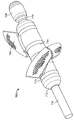
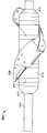
도 1은 펼쳐져 전개된 구성의 심혈관의 유동 보조 장치의 일 실시예의 기울어진 상태의 정면도이며;
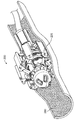
도 2는 그 안에 펼쳐져 전개된 구성으로 위치 설정된, 심혈관의 유동 보조 장치의 일 실시예를 도시하는 대동맥의 기울어진 상태의 횡 단면도이며;
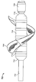
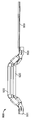
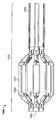
도 3은 접혀져서 전달 가능한 구성의 심혈관의 유동 보조 장치의 일 실시예를 예시하는 기울어진 상태의 정면도이며;
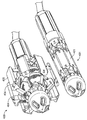
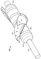
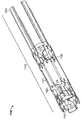
도 4a는 접혀져서 전달 가능한 구성의 다른 심혈관의 유동 보조 장치와 나란한 펼쳐져 전개된 구성의 심혈관의 유동 보조 장치의 일 실시예를 도시하는 기울어진 상태의 정면도이며;
도 4b는 도 4a의 접혀져서 전달 가능한 구성의 다른 심혈관의 유동 보조 장치와 나란한 펼쳐져 전개된 구성의 심혈관의 유동 보조 장치의 동일한 실시예를 도시하는 측면도이며;
도 5a는 나선형 스크류 펌프의 어느 한 측부로부터 제거된 두 개의 케이지 지지 부재들을 도시하는, 펼쳐져 전개된 구성의 심혈관의 유동 보조 장치의 일 실시예의 측면도이며;
도 5b는 하나가 블레이드에 부착된, 심혈관의 유동 보조 장치의 외측 샤프트 부분 블레이드 부착 세그먼트의 일 실시예의 기울어진 상태의 측면도이며,
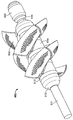
도 6a는 펼쳐진 구성의 두 개의 세트들의 나선형 블레이드들을 도시하는, 심혈관의 유동 보조 장치의 나선형 스크류 펌프의 일 실시예의 기울어진 상태의 정면도이며,
도 6b는 두 개의 세트들의 나선형 블레이드들을 펼쳐진 구성으로 도시한, 도 6a의 심혈관의 유동 보조 장치의 나선형 스크류 펌프의 동일한 실시예의 측면도이며,
도 7a는 하나의 세트의 나선형 블레이드들을 도시하는, 펼쳐진 구성의 심혈관의 유동 보조 장치의 나선형 스크류 펌프의 일 실시예의 기울어진 상태의 정면도이며;
도 7b는 한 세트의 나선형 블레이드들을 펼쳐진 구성으로 도시하는, 도 7a의 심혈관의 유동 보조 장치의 나선형 스크류 펌프의 동일한 실시예의 측면도이며;
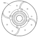
도 7c는 펼쳐진 구성의 한 세트의 나선형 블레이드들을 도시하는, 도 7a의 심혈관의 유동 보조 장치의 나선형 스크류 펌프의 동일한 실시예의 전면도(front-on view)이며;
도 8a는 하나의 세트의 나선형 블레이드들을 접혀진 구성으로 도시하는, 심혈관의 유동 보조 장치의 나선형 스크류 펌프의 일 실시예의 기울어진 상태의 정면도이며;
도 8b는 하나의 세트의 나선형 블레이드들을 접혀진 구성으로 도시하는, 도 8a의 심혈관의 유동 보조 장치의 나선형 스크류 펌프의 동일한 실시예를 예시하는 측면도이며;
도 8c는 하나의 세트의 나선형 블레이드들을 접혀진 구성으로 도시하는, 심혈관의 유동 보조 장치의 나선형 스크류 펌프의 동일한 실시예의 전면도이며;
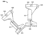
도 9a는 펼쳐진 구성의 단일 케이지 암 내로 함께 형성된 두 개의 케이지 지지 부재들의 일 실시예의 기울어진 상태의 정면도이며;
도 9b는 도 9a의 펼쳐진 구성의 단일 케이지 암 내로 함께 형성되는 두 개의 케이지 지지 부재들의 동일한 실시예의 측면도이며;
도 9c는 도 9a의 펼쳐진 구성에서 단일 케이지 암 내로 함께 형성되는 두 개의 케이지 지지 부재의 일 실시예의 평면도이며;
고 9d는 도 9a의 펼쳐진 구성의 단일 케이지 암 내로 함께 형성되는 두 개의 케이지 지지 부재들의 동일한 실시예를 예시하는 전면도이며;
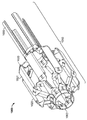
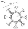
도 10a는 펼쳐진 구성의 완전한 바구니-형 케이지를 형성하기 위하여 함께 조합된 4개의 케이지 암들의 일 실시예의 기울어진 상태의 정면도이며;
도 10b는 도 10a의 펼쳐진 구성의 완전한 바구니-형 케이지를 형성하기 위하여 함께 조합된 4개의 케이지 암들의 동일한 실시예의 측면도이며;
도 10c는 도 10a의 펼쳐진 구성의 완전한 바구니-형 케이지를 형성하기 위하여 함께 조합된 4개의 케이지 암들의 동일한 실시예의 전면도이며;
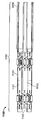
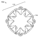
도 11a는 접혀진 구성의 완전한 바구니-형 케이지를 형성하기 위하여 함께 조합된 4개의 케이지 암들의 일 실시예의 기울어진 상태의 정면도이며;
도 11b는 도 11a의 접혀진 구성의 완전한 바구니-형 케이지를 형성하기 위하여 함께 조합된 4개의 케이지 암들의 동일한 실시예의 측면도이며;
도 11c는 도 11a의 접혀진 구성의 완전한 바구니-형 케이지를 형성하도록 함께 조합된 4개의 케이지 암들의 동일한 실시예의 전면도이며;
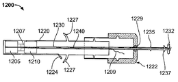
도 12a는 전달 덮개 내에 위치된 장치의 동맥 폐쇄 디스크들을 도시하는, 동맥 폐쇄 장치의 일 실시예의 측면도이며;
도 12b는 전달 덮개의 말단부로부터 펼쳐져 전개되는 말단 디스크 동맥 폐쇄 디스크를 도 12a의 동맥 폐쇄 장치의 동일한 실시예의 측면도이며;
도 12c는 전달 덮개의 말단부로부터 펼쳐져 전개되는 말단 및 선단 동맥 폐쇄 디스크들 양자 모두를 도시하는, 도 12a의 동맥 폐쇄 장치의 동일한 실시예의 측면도이며;
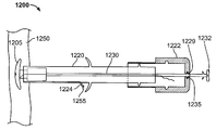
도 12d는 전달 덮개가 제거되어 완전히 전개된 동맥 폐쇄 디스크들의 일 실시예의 측면도이며;
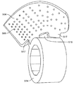
도 12e는 디스크들을 이들의 전개된 구성으로 펼쳐지도록 하기 위해 사용된 스트럿들을 도시하는, 동맥 폐쇄 디스크들의 일 실시의 도면이며;
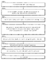
도 13은 본 명세서의 일 실시예에 따라, 한자의 하행 대동맥 내에 혈류 역학적 유동 보조 장치를 이식하는 단계를 포함하는 단계들을 예시하는 흐름도이며;
도 14는 본 명세서의 일 실시예에 따라, 동맥 폐쇄 장치를 사용하여 동맥 접근 지점을 폐쇄하는 단계를 포함하는 단계들을 예시하는 흐름도이다.These and other features and advantages of the present invention will be further appreciated as these and other features and advantages of the present invention will become better understood with reference to the detailed description when considered in connection with the accompanying drawings.
BRIEF DESCRIPTION OF THE DRAWINGS Figure 1 is a front elevation view of a tilted state of an embodiment of an expanded and deployed cardiovascular flow assist device;
Figure 2 is a transverse cross-sectional view of the aorta in an inclined state showing an embodiment of a cardiovascular flow assist device positioned therein in a deployed configuration;
Figure 3 is a front elevation view in an inclined state illustrating an embodiment of a collapsible and deliverable cardiovascular flow assist device;
Figure 4a is a front elevation view in an inclined state showing one embodiment of a cardiovascular flow assist device in a deployed and deployed configuration in parallel with other cardiovascular flow assist devices of a collapsible and deliverable configuration;
Figure 4b is a side view showing an identical embodiment of a cardiovascular flow assist device in a deployed and deployed configuration in parallel with the other cardiovascular flow assist devices of the collapsible and deliverable configuration of Figure 4a;
5A is a side view of one embodiment of a cardiovascular flow assist device in an expanded and deployed configuration depicting two cage support members removed from either side of a helical screw pump;
Figure 5B is a side view of the tilted state of one embodiment of the outer shaft portion blade attachment segment of the cardiovascular flow assist device, one of which is attached to the blade,
6A is a front elevation view of a tilted state of one embodiment of a helical screw pump of a cardiovascular flow assist device, showing the two sets of helical blades of an unfolded configuration,
Figure 6b is a side view of the same embodiment of the helical screw pump of the cardiovascular flow assist device of Figure 6a, showing the two sets of helical blades in an expanded configuration,
7A is a front elevation view of an angled state of one embodiment of a helical screw pump of a cardiovascular flow assist device of an unfolded configuration, showing one set of helical blades;
Figure 7b is a side view of the same embodiment of the helical screw pump of the cardiovascular flow assist device of Figure 7a, showing a set of helical blades in an expanded configuration;
Figure 7C is a front-on view of the same embodiment of a helical screw pump of the cardiovascular flow assist device of Figure 7A, showing a set of helical blades in an unfolded configuration;
8A is a front elevational view of one embodiment of a helical screw pump of a cardiovascular flow assist device, showing one set of helical blades in a folded configuration;
Figure 8b is a side view illustrating the same embodiment of a helical screw pump of the cardiovascular flow assist device of Figure 8a, which illustrates one set of helical blades in a folded configuration;
Figure 8c is a front view of the same embodiment of a helical screw pump of a cardiovascular flow assist device, showing one set of helical blades in a folded configuration;
9A is a front view of an inclined state of one embodiment of two cage support members formed integrally into a single cage arm of an unfolded configuration;
Figure 9b is a side view of the same embodiment of two cage support members formed together in a single cage arm of the expanded configuration of Figure 9a;
Figure 9C is a top view of one embodiment of two cage support members formed together into a single cage arm in the expanded configuration of Figure 9A;
9d is a front view illustrating an identical embodiment of two cage support members formed together into a single cage arm of the expanded configuration of Fig. 9a; Fig.
10A is a front elevation view of an inclined state of one embodiment of four cage arms joined together to form a complete basket-type cage in an unfolded configuration;
Figure 10B is a side view of the same embodiment of the four cage arms combined together to form a complete basket-type cage of the expanded configuration of Figure 10A;
Figure 10c is a front view of the same embodiment of the four cage arms combined together to form a complete basket-type cage of the expanded configuration of Figure 10a;
11A is a front elevation view of an inclined state of one embodiment of four cage arms joined together to form a complete basket-type cage of a folded configuration;
FIG. 11B is a side view of the same embodiment of the four cage arms combined together to form a complete basket-type cage of the folded configuration of FIG. 11A; FIG.
11C is a front view of the same embodiment of four cage arms combined together to form a complete basket-type cage of the folded configuration of FIG. 11A;
12A is a side view of an embodiment of an arterial occlusion device, showing artery occlusion discs of a device located within a delivery lid;
FIG. 12B is a side view of the same embodiment of the arterial occlusion device of FIG. 12A, with the distal disc artery occlusion disk deployed and deployed from the distal end of the delivery lid;
12C is a side view of the same embodiment of the arterial occlusion device of FIG. 12A, showing both the distal and distal artery occlusion discs deploying and deploying from the distal end of the delivery sheath;
12D is a side view of one embodiment of the fully deployed arterial occlusion discs with the transfer sheath removed;
12E is an embodiment of the artery occlusion discs showing the struts used to expose the discs in their deployed configuration;
13 is a flow chart illustrating steps including implanting a hemodynamic flow assist device within the descending aorta of a Chinese character, according to one embodiment of the present disclosure;
14 is a flow chart illustrating steps including closing an arterial access point using an arterial occlusion device, in accordance with an embodiment of the present disclosure.
본 명세서는 최소의 외과적 방식(minimally invasive manner)으로 이식되고 제거되고 혈류 역학적으로 손상된 환자(hemodynamically compromised patient)들에서 혈류를 증가시키기 위한 작용을 하는 혈관 내, 접을 수 있는 펌핑 장치에 관한 것이다. 상기 장치는 대동맥궁 하류의 대동맥 내에 위치 설정되고 전신 혈류를 증가시킴으로써 병든 심장의 부담을 제거한다(offload). 일 실시예에서, 상기 장치는 선단부와 말단부를 구비한 세장형의 원통 형상 장치이며, 이 장치는 소형 펌프, 상기 펌프를 둘러싸는 바구니형 케이스, 및 펌프를 구동하기 위한 모터를 포함한다. 일 실시예에서, 모터를 위한 동력은 내부 배터리에 의해 공급된다. 다른 실시예에서, 하나 이상의 와이어가 상기 장치의 선단부로부터 연장하여 상기 장치에 동력을 제공한다.
The present disclosure relates to an intravascular, collapsible pumping device that acts to increase blood flow in hemodynamically compromised patients who have been implanted and removed in a minimally invasive manner and hemodynamically compromised patients. The device is positioned in the aorta downstream of the aortic arch and increases the systemic blood flow to offload the diseased heart. In one embodiment, the device is a elongated cylindrical device having a tip and a distal end, the device comprising a miniature pump, a basket case enclosing the pump, and a motor for driving the pump. In one embodiment, the power for the motor is supplied by the internal battery. In another embodiment, one or more wires extend from the distal end of the device to provide power to the device.
선택적으로, 일 실시예에서, 와이어는 또한 상기 장치의 제어를 제공한다. 일실시예에서, 상기 장치는 이의 말단부에 캡을 포함한다. 일 실시예에서, 펌프는 아르키메데스의 펌프와 같은 나선형 스크류 펌프이며, 이는 하나 이상의 세트의 접을 수 있는 펌프 블레이들이 부착된 회전 샤프트를 포함한다. 일 실시예에서, 회전 샤프트는 내부 부분 및 외부 부분을 포함하며, 내부 부분은 부분적으로 외부 부분 내외로 미끄럼 가능하게 움직일 수 있다. 일 실시예에서, 샤프트 상에 사전 부하식 압축 분리 링들은 액밀 밀봉들을 제공하고 가요적 커플링 및 펌프 블레이드들 상의 압력에 의해 도입된 임의의 축방향 변위를 허용한다. 케이지는 다수의 지지 부재들로 구성되고 펌프에 지지를 제공하고 펌프를 하향 대동맥 내에 고정한다. 펌프 블레이드들 및 케이지 지지 부재들의 부분들은 상기 장치가 전달가능하고 접혀진 제 1 구성으로부터 전개되어 펼쳐진 제 2 구성으로 변화하는 것을 허용하는 형상 메모리 금속으로 구성된다. 일 실시예에서, 펌프 블레이드들 및 각각의 지지 부재의 부분들은 니티놀(Nitinol)로 구성된다. 일 실시예에서, 상기 장치가 접힐 때, 회전하는 샤프트의 내부 부분은 외부 부분으로부터 부분적으로 연장하여, 접혀진 구성에 있을 때 상기 장치가 세장형이 되는 것을 유발한다. 동시에, 펌프 블레이들 및 케이지 지지 부재들은 장치의 중심을 향하여 접혀져서, 상기 장치의 총 직경이 접혀진 구성에 있는 동안 감소되는 것을 초래한다.
Optionally, in one embodiment, the wire also provides control of the apparatus. In one embodiment, the device includes a cap at its distal end. In one embodiment, the pump is a helical screw pump, such as the pump of Archimedes, which includes a rotating shaft to which one or more sets of collapsible pump blades are attached. In one embodiment, the rotating shaft includes an inner portion and an outer portion, wherein the inner portion is slidably movable in and out of the outer portion. In one embodiment, preloaded compression split rings on the shaft provide fluid tight seals and allow any axial displacement introduced by the pressure on the flexible couplings and pump blades. The cage is composed of a number of support members and provides support to the pump and fixes the pump in the downward aorta. The portions of the pump blades and the cage support members consist of a shape memory metal that allows the device to change from a first, collapsible, first configuration to a deployed, second configuration. In one embodiment, the pump blades and portions of each support member are constructed of Nitinol. In one embodiment, when the device is folded, the inner portion of the rotating shaft partially extends from the outer portion, causing the device to become elongated when in a folded configuration. At the same time, the pump blades and cage support members are folded toward the center of the device, resulting in the total diameter of the device being reduced while in the folded configuration.
일 실시예에서, 본 명세서의 혈관 내, 접을 수 있는 펌핑 장치는 하나 이상의 센서를 포함한다. 일 실시예에서, 센서는 풀 3D 공간 프로파일 압력 쿼드-센서(full 3D space profile pressure quad-sensor)이다. 다른 실시예에서, 센서는 유입 쿼드-센서이다. 다른 실시예에서, 센서는 온도 및 유출 쿼드-센서이다. 센서는 장치의 임의의 단계에서 비교가능한 센서 쌍들의 차이들을 기초로 하여 초기 위치 설정 및 초기 대동맥 벽 인접성에 관한 정보를 릴레이하기 위하여 사용된다. 일 실시예에서, 센서는 보건 의료 전문가에게 생명유지에 필수적인 장치 기능 정보를 제공한다. 다른 실시예에서, 상기 장치는 상기 장치의 길이를 따라 상이한 위치들에 위치 설정된 두 개 또는 세 개 이상의 센서들을 포함한다. 일 실시예에서, 제 1 센서는 상기 장치의 말단부에 근접하게 위치 설정되고 제 2 센서는 상기 장치의 선단부에 근접하게 위치 설정된다. 제 1 센서와 제 2 센서 사이에서 측정된 값들에서의 차이들은 유동 속도 및 상기 장치의 기능을 결정하기 위해 사용된다. 일 실시예에서, 본 명세서의 혈관 내 접을 수 있는 펌핑 장치는 하나 이상의 카메라를 포함한다. 일 실시예에서, 카메라는 장치의 말단부에 근접하게 위치 설정된다. 일 실시예에서, 카메라는 적외선(IR) 전하 결합 소자(CCD) 카메라이다.
In one embodiment, the intravascular, collapsible pumping device herein includes one or more sensors. In one embodiment, the sensor is a full 3D space profile pressure quad-sensor. In another embodiment, the sensor is an inflow quad-sensor. In another embodiment, the sensor is a temperature and a leaking quad-sensor. The sensor is used to relay information regarding initial positioning and initial aortic wall proximity based on differences of comparable sensor pairs at any stage of the device. In one embodiment, the sensor provides the healthcare professional with device capability information that is essential for life support. In another embodiment, the apparatus includes two or more sensors positioned at different positions along the length of the apparatus. In one embodiment, the first sensor is positioned proximate the distal end of the device and the second sensor is positioned proximate the distal end of the device. Differences in measured values between the first sensor and the second sensor are used to determine the flow rate and the function of the device. In one embodiment, the intravascular collapsible pumping device herein includes one or more cameras. In one embodiment, the camera is positioned proximate the distal end of the device. In one embodiment, the camera is an infrared (IR) charge coupled device (CCD) camera.
일 실시예에서, 장치는 환자의 동맥을 통하여 경피적으로 이식된다. 일 실시예에서, 상기 장치는 대퇴 동맥을 통해 도입된다. 다른 실시예에서, 장치는 외부 장골 동맥을 통해 도입된다. 다른 실시예에서, 장치는 총 장골 동맥을 통해 도입된다. 또 다른 실시예에서, 장치는 쇄골하 동맥을 통해 도입된다. 일 실시예에서, 구멍은 환자의 허벅지 영역에 형성되고 덮개는 대퇴 동맥 내로 도입되고 이의 말단 단부는 대동맥 내에 위치 설정된다. 장치는 덮개 내로 기계식으로 삽입된다. 덮개는 펼쳐진 구성에서 장치의 직경보다 작고 접혀진 구성에서 장치의 직경보다 크다. 일 실시예에서, 장치를 덮개 내로 삽입하는 작업은 장치를 접혀진 상태로 압축하는 것을 유발한다. 덮개 및 접혀진 장치는 환자의 대동맥 내로 원하는 전개 위치로 전진된다. 일 실시예에서, 장치는 좌측 완두 동맥으로부터 바로 아래 하행 대동맥 내에서 전개된다. 다른 실시예에서, 장치는 신장 동맥들로부터 바로 아래 하행 대동맥 내에서 전개된다. 다양한 다른 실시예들에서, 장치는 그 안에 포함된 어떠한 지류(branch)들도 폐색되지 않도록 주의하면서 좌측 완두 동맥과 신장 동맥들로부터 바로 아래 사이의 하행 대동맥을 따라 어디에서든 전개된다. 다양한 다른 실시예들에서, 쇄골하, 액와 또는 상완 동맥들을 통하여 접근이 이루어진다.
In one embodiment, the device is implanted percutaneously through a patient ' s artery. In one embodiment, the device is introduced through the femoral artery. In another embodiment, the device is introduced through an external iliac artery. In another embodiment, the device is introduced through the total iliac artery. In another embodiment, the device is introduced through the subclavian artery. In one embodiment, a hole is formed in the thigh region of the patient, a lid is introduced into the femoral artery and its distal end is positioned within the aorta. The device is inserted mechanically into the lid. The cover is smaller than the diameter of the device in the deployed configuration and greater than the diameter of the device in the folded configuration. In one embodiment, the operation of inserting the device into the lid causes compression of the device into a folded state. The lid and the folded device are advanced into the desired deployment position into the patient ' s aorta. In one embodiment, the device is deployed in the descending aorta immediately below the left pharyngeal artery. In another embodiment, the device is deployed in the descending aorta immediately below the renal arteries. In various other embodiments, the device is deployed anywhere along the descending aorta between the left pharyngeal artery and the renal arteries immediately beneath it, taking care not to block any branches contained therein. In various other embodiments, access is made through the subclavian, axillary, or brachial arteries.
덮개 및 장치가 소망하는 전개 위치에 도달하면, 부착된 위치 설정 샤프트에 의해 장치가 제 위치에 유지되는 동안 덮개가 오므려진다. 위치 설정 샤프트는 선단부 및 말단부를 가지는 세장형이며 가요성의 중실형 샤프트이다. 샤프트의 말단부는 스크류 또는 클립을 사용하여 장치의 말단부에 부착되고 샤프트는 덮개의 전체 길이를 횡단한다. 샤프트의 선단부가 덮개의 선단부로부터 나오고 덮개 외부를 조작할 수 있는 선단 노브(proximal knob)를 포함한다. 상기 장치가 적절하게 위치 설정된 후 상기 샤프트는 록킹 해제 메커니즘을 통해 장치로부터 분리된다. 일 실시예에서, 덮개가 상기 장치로부터 제거되면, 펌프 블레이드들 및 케이지 지지 부재들이 펼쳐지고 회전 샤프트의 내부 부분이 부분적으로 상기 샤프트의 외부 부분 내로 신축한다. 다른 실시예에서, 회전 샤프트의 말단 부분은 펼쳐진 구성에 있을 때 말단 캡 내로 부분적으로 연장한다. 이러한 실시예에서, 말단 캡은 회전 샤프트의 말단 부분을 수용하기 위하여 유체로 채워진 공동을 포함한다. 케이지가 펼쳐질 때 유체가 제거된다. 장치가 전개되어 펼쳐진 구성으로 변화될 때, 장치의 길이가 짧아지고 직경이 증가한다. 케이지 지지 부재들은 대동맥의 벽들 상에 놓이고 펌프 블레이드들이 부착된 회전 샤프트는 케이지 내에서 자유롭게 스핀한다(spin). 위치 설정 샤프트는 장치의 선단부로부터 결합 해제되고 덮개로부터 제거된다. 덮개는 이어서 환자로부터 제거된다. 장치가 내부 배터리를 가지는 실시예에서, 구멍 위치는 봉합되어 폐쇄된다. 장치가 동력 및/또는 제어 와이어를 포함하는 대안적인 일 실시예에서, 상기 와이어는 구멍 위치로부터 연장하여 환자의 피부에 고정된다. 일 실시예에서, 와이어는 벨트 또는 벨트 높이의 속옷에 위치하는 배터리 및/또는 제어 팩으로 연장한다.
When the cover and the device reach the desired deployment position, the cover is pinched while the device is held in place by the attached positioning shaft. The positioning shaft is a elongated, flexible, solid shaft having a distal end and a distal end. The distal end of the shaft is attached to the distal end of the device using a screw or clip and the shaft traverses the entire length of the lid. And includes a proximal knob through which the distal end of the shaft comes out of the distal end of the lid and can manipulate the outside of the lid. After the device is properly positioned, the shaft is disengaged from the device via the unlocking mechanism. In one embodiment, when the lid is removed from the apparatus, the pump blades and cage support members unfold and the inner portion of the rotating shaft partially extends into the outer portion of the shaft. In another embodiment, the distal end portion of the rotating shaft partially extends into the end cap when in the deployed configuration. In such an embodiment, the end cap includes a fluid-filled cavity to receive the distal portion of the rotating shaft. The fluid is removed when the cage is unfolded. When the device is changed to an unfolded configuration, the length of the device is shortened and the diameter is increased. The cage support members are placed on the walls of the aorta and the rotating shaft to which the pump blades are attached is free to spin in the cage. The positioning shaft is disengaged from the distal end of the device and removed from the lid. The lid is then removed from the patient. In an embodiment in which the device has an internal battery, the hole position is sealed and closed. In an alternate embodiment in which the device comprises a power and / or control wire, the wire extends from the hole position and is secured to the patient ' s skin. In one embodiment, the wire extends into a battery and / or control pack located in the undergarment of belt or belt height.
본 명세서는 또한 환자의 대동맥으로부터 펌핑 장치를 제거하기 위해 사용된 회수 장치에 관한 것이다. 일 실시예에서, 회수 장치는 발명의 명칭이 "심부전/혈류 역학적 장치(Heart Failure/Hemodynamic Device)"이고 본 발명의 출원인에게 양도된 미국 특허 제 7,878,967호"에 설명된 것과 유사하며, 이 특허는 전체적으로 인용에 의해 포함된다. 일 실시예에서, 펌핑 장치가 제거될 준비가 되면, 덮개는 남아 있는 경우, 동력 및/또는 제어 와이어를 사용하여 대퇴 동맥 내로 경피적으로 다시 한번 도입된다. 다른 실시예에서, 제어 및 동력 와이어들은 장치의 선단 부분의 대각선 방향으로 마주하는 단부들로부터 나오는 두 개 이상의 개별 와이어들을 포함한다. 이어서 제거 장치는 덮개 내로 삽입되어 제거 장치 및 덮개가 맥관 구조를 통하여 하행 대동맥 내로 그리고 펌핑 장치까지 전진된다. 이어서 회수 장치는 덮개의 단부를 넘어 더 전진한다. 회수 장치의 말단부는 펌핑 장치의 선단부와 인터페이싱하여 펌핑 장치가 회수 장치로 연결된다. 이러한 연결은 기계적 록킹 메커니즘일 수 있거나 자기적으로 보조될 수 있다. 회수 장치는 이어서 덮개 내로 수축되어 덮개와 함께 펌핑 장치를 가져온다. 부착된 선단 와이어들 및 일 실시예에서 부가된 강도에 대해 보강되는 둘러싸는 와이어 재킷은 장치를 덮개 내로 다시 당기기 위해 사용될 수 있다. 케이지가 덮개와 접촉할 때, 지지 부재들은 펌핑 장치를 향하여 다시 압축된다. 케이지의 압축은 회전 샤프트의 내부 부분이 상기 회전 샤프트의 외부 부분으로부터 외부로 부분적으로 연장하는 것을 유발한다. 다른 실시예에서, 말단 캡은 공동을 압축하여 샤프트의 말단 부분을 수용하고, 말단 캡은 샤프트로부터 멀리 연장하고 상기 공동은 회수 동안 혈액으로 채워진다. 일 실시예에서, 케이지가 점차적으로 접힘에 따라, 나선형 펌프 블레이드들을 구비한 샤프트는 역회전한다. 초기 블레이드 형상 및 완전히 펼쳐진 블레이드 형상은 역회전할 때 블레이드들이 변형되는 것을 허용하고 삽입 단계에서와 동일한 형상을 취하는 블레이드 프로파일로 전개된다. 일 실시예에서, 둘러싸인 케이지의 내부 구성 및 상세들은 펌프 블레이드들에 대한 추가 지지 및 안내를 제공하게 되어 이들의 변형을 보조하고 압축된 케이지의 내측 형상에 이들을 유효하게 배치한다. 케이지 지지 부재들의 압축 및 회전 샤프트 내부 부분의 연장은 나선형 펌프 블레이드들의 접힘을 초래한다. 부착된 회수 장치를 통한 덮개 내로의 펌핑 장치의 당김은 펌핑 장치가 이의 접혀진 회수 가능한 구성으로 다시 복귀하게 한다. 덮개 내로 완전히 수축되면, 부착된 회수 장치 및 덮개를 따라, 펌핑 장치는 대퇴 동맥을 통하여 제거되고 접근 위치가 봉합되어 폐쇄된다. 일 실시예에서, 조리(sieve)형 필터는 회수 장치의 말단부에 부착된다. 회수 장치가 덮개의 말단부를 넘어 연장될 때 이러한 원형 필터가 전개된다. 필터는 펌핑 장치를 회수하는 프로세스에서 제거되는 어떠한 부스러기도 포획한다. 이어서 필터는 또한 상기 장치가 덮개 내로 수축된 후 장치를 따라 덮개 내로 접혀진다.
The present disclosure also relates to a collection device used to remove a pumping device from a patient's aorta. In one embodiment, the collection device is similar to that described in U. S. Patent No. 7,878, 967 entitled " Heart Failure / Hemodynamic Device ", assigned to the assignee of the present invention, In one embodiment, once the pumping device is ready to be removed, the lid is once again percutaneously introduced into the femoral artery using power and / or control wires, if remaining. In another embodiment The control and power wires include two or more separate wires coming out of the diagonally opposite ends of the distal portion of the device. The removal device is then inserted into the lid so that the removal device and the lid are inserted into the descending aorta through the vasculature structure The recovery device then advances further beyond the end of the lid. The distal end of the recovery device The pumping device is connected to the recovery device by interfacing with the tip of the pumping device, which may be a mechanical locking mechanism or magnetically assisted. The recovery device is then retracted into the lid to bring the pumping device with the lid. The wrapped wire jackets reinforced with the tip wires and the added strength in one embodiment can be used to pull the device back into the lid. When the cage contacts the lid, the support members are again compressed toward the pumping device Compression of the cage causes the inner portion of the rotating shaft to partially extend outwardly from the outer portion of the rotating shaft. In another embodiment, the end cap compresses the cavity to receive the distal portion of the shaft, Extends away from the shaft and the cavity is filled with blood during withdrawal. In an embodiment, as the cage progressively collapses, the shaft with the helical pump blades reverses. The initial blade shape and the fully extended blade shape allow the blades to deform when reversing, The inner configuration and details of the enclosed cage provide additional support and guidance for the pump blades to assist in their deformation and to make them effective in the inner shape of the compressed cage . Compression of the cage support members and extension of the interior portion of the rotating shaft results in folding of the helical pump blades. Pulling of the pumping device through the attached recovery device into the lid causes the pumping device to return to its folded, retractable configuration. Once fully retracted into the lid, along with the attached collection device and lid, the pumping device is removed through the femoral artery and the access position is closed and closed. In one embodiment, the sieve type filter is attached to the distal end of the collection device. This circular filter is deployed when the collection device extends beyond the distal end of the lid. The filter captures any debris that is removed in the process of recovering the pumping device. The filter is then folded into the lid along with the device after the device is retracted into the lid.
일 실시예에서, 장치의 회수는 펌핑 장치의 선단부부에 부착된 두 개의 와이어들을 이용한다. 회수 장치는 회수 장치를 펌핑 장치로 안내하기 위한 레일들로서 두 개의 와이어들을 사용하여 접근 용기 내로 삽입된다. 일 실시예에서, 와이어들은 인장 상태에 있을 때 펌핑 장치의 샤프트를 길게 늘이기 위해 사용될 수 있어 회수 전에 장치를 접는다.
In one embodiment, the recovery of the device utilizes two wires attached to the leading end of the pumping device. The collection device is inserted into the access container using two wires as rails for guiding the collection device to the pumping device. In one embodiment, the wires can be used to stretch the shaft of the pumping device when in tension, thereby folding the device before withdrawal.
다른 실시예에서, 펌핑 장치는 내부 배터리를 포함하고 와이어들이 환자의 신체로부터 연장하지 않고, 장치의 회수를 위해 자성을 이용한다. 펌핑 장치의 선단부 및 회수 장치의 말단부는 반대 극성들로 자화되어 펌핑 장치의 선단부 및 회수 장치의 말단부는 회수 장치가 전개된 펌핑 장치로 전진될 때 연결될 것이다.
In another embodiment, the pumping device includes an internal battery and the wires do not extend from the patient ' s body and utilize magnetism to recover the device. The tip of the pumping device and the distal end of the recovery device are magnetized to opposite polarities so that the tip of the pumping device and the distal end of the recovery device will be connected when the recovery device is advanced to the deployed pumping device.
선택적으로, 일 실시예에서, 펌프의 회전 샤프트는 내부 및 외부 부분들이 아닌 늘어날 수 있는 재료로 구성된다. 장치가 접힐 때, 샤프트가 늘어나서, 장치의 길이가 증가한다. 삽입 덮개로부터 해제되면, 샤프트는 이의 디폴트 형태(default shape)로 수축된다. 이러한 실시예에서, 하나 이상의 세트의 블레이드들은 단지 샤프트의 선단부 및 말단부에 부착된다. 샤프트가 늘어나면, 블레이드 및 케이지 지지 부재가 늘어나고 상기 샤프트의 중심을 향하여 압축한다. 샤프트가 이의 디플트 형상으로 수축되면, 블레이드들은 이들의 작동 가능한 펼쳐진 구성으로 복귀된다.
Optionally, in one embodiment, the rotating shaft of the pump is composed of a material that can extend, not internal and external portions. When the device is folded, the shaft is stretched and the length of the device increases. When released from the insert cover, the shaft contracts to its default shape. In this embodiment, one or more sets of blades are attached only to the distal and distal ends of the shaft. As the shaft is stretched, the blade and cage support members stretch and compress toward the center of the shaft. When the shaft is contracted in its deflected configuration, the blades are returned to their operable unfolded configuration.
선택적으로, 일 실시예에서, 하나 이상의 세트의 블레이드들은 단지 샤프트의 선단부 및 말단부에 위치된 베어링들에 부착된다. 이러한 실시예에서, 단지 블레이드들이 베어링들과 함께 회전한다. 일 실시예에서, 블레이드들은 자기 커플링을 통해 회전된다. 샤프트는 회전하지 않아서, 더 적은 가동 부분들 및 더 낮은 동력 소모를 초래한다. 이러한 실시예는 위에서 설명된 바와 같이 늘어날 수 있는 샤프트 또는 신축성 샤프트 상에 활용될 수 있다.
Optionally, in one embodiment, the blades of the at least one set are attached to the bearings located at the distal and distal ends of the shaft only. In this embodiment, only the blades rotate with the bearings. In one embodiment, the blades are rotated through magnetic coupling. The shaft does not rotate, resulting in fewer moving parts and lower power consumption. This embodiment can be utilized on a shaft or stretchable shaft that can be stretched as described above.
선택적으로, 일 실시예에서, 바구니-형 케이지는 고정자로서 작용하고 블레이드들을 회전시켜 전체 나선형 블레이드 세트(들) 및 케이지가 자기적으로 작용하여 무철심형 모터의 회전자가 되어, 장치의 선단부에서 전기 모터가 요구되지 않는다. 이러한 실시예에서, 블레이드들은 자기장 재료로 구성되고 케이지 구성요소들은 유극 자기장을 전기적으로 유도하기 위한 능력을 보유한다.
Alternatively, in one embodiment, the basket-type cage acts as a stator and rotates the blades so that the entire spiral blade set (s) and the cage magnetically act to become the rotor of the ironless motor, Is not required. In such an embodiment, the blades are constructed of a magnetic field material and the cage components have the ability to electrically induce the field magnetic field.
선택적으로, 일 실시예에서, 장치는 단지 케이지 내에 위치 설정된 접을 수 있고 연속적인 실린더를 포함한다. 실린더는 이의 말단부 및 선단부에서 개방되어 혈액의 통과를 허용한다. 펌프의 블레이드들과 실린더 사이의 간격이 최소이어서, 블레이드들 주위의 누출 양을 감소시킴으로써 장치의 효율을 개선한다. 일 실시예에서, 블레이들 및 실린더는 또한 하전되어 실린더가 자기적으로 부양되어 블레이드들과 접촉되지 않는다.
Optionally, in one embodiment, the apparatus comprises a collapsible and continuous cylinder positioned only in the cage. The cylinder is open at its distal end and distal end to allow passage of blood. The spacing between the blades of the pump and the cylinder is minimal, thereby improving the efficiency of the apparatus by reducing the amount of leakage around the blades. In one embodiment, the blades and cylinders are also charged so that the cylinders are magnetically levitated and are not in contact with the blades.
선택적으로, 일 실시예에서, 장치는 바구니형 케이지 대신에 접을 수 있는 연속적인 실린더를 포함한다. 실린더는 이의 말단부 및 선단부에서 개방되어 혈액의 통과를 허용한다. 실린더의 외주변은 대동맥의 내벽에 놓인다. 일 실시예에서, 실린더는 접을 수 있는 스트럿들을 통해 상기 장치에 부착된다. 펌프의 블레이드들과 실린더 사이의 간격은 최소이어서, 블레이드들 주위로의 누출의 양을 감소시킴으로써 장치의 효율을 개선한다.
Optionally, in one embodiment, the apparatus comprises a continuous, collapsible cylinder instead of a basket-shaped cage. The cylinder is open at its distal end and distal end to allow passage of blood. The outer periphery of the cylinder lies on the inner wall of the aorta. In one embodiment, the cylinder is attached to the device through collapsible struts. The spacing between the blades of the pump and the cylinder is minimal, thereby improving the efficiency of the apparatus by reducing the amount of leakage around the blades.
선택적으로, 일 실시예에서, 상기 장치는 환자의 대동맥의 크기에 의존하여 장치의 직경을 전개된 구성으로 맞추기 위한 메커니즘을 포함한다. 일 실시예에서, 장치의 선단부로부터 이어지는 동력/제어 와이어는 의사가 외부 샤프트 부분 내에 내부 샤프트 부분을 연장하거나 또는 수축함으로써 케이지 직경에서 다이얼로 조정하는 것을 가능하게 한다.
Optionally, in one embodiment, the device comprises a mechanism for adjusting the diameter of the device to the deployed configuration, depending on the size of the aorta of the patient. In one embodiment, the power / control wire leading from the distal end of the device enables the physician to adjust the dial from the cage diameter by extending or retracting the inner shaft portion within the outer shaft portion.
선택적으로, 일 실시예에서, 상기 장치는 펼쳐진 구성에 있을 때 상기 장치는 약간의 타원형 형상을 가지는 방식으로 설계되며, 이 타원형 형상 내에서 선단부가 말단부 보다 직경이 약간 더 작다. 이 같은 설계는 두 개 이상의 장점을 제공한다. 첫번째, 상기 장치는 원뿔과 같은 대동맥에 놓여져 장치에 의해 경험된 일정한 혈류 및 전진 압력에 의해 유발된 이동을 저지한다. 두번째, 상기 장치가 덮개 내로 다시 더 용이하게 끼워 맞춤에 따라 상기 장치가 더 용이하게 회수된다.
Optionally, in one embodiment, when the device is in an unfolded configuration, the device is designed in such a way that it has a slight elliptical shape in which the tip is slightly smaller in diameter than the tip. This design offers more than two advantages. First, the device is placed in the aorta such as a cone to prevent movement caused by constant blood flow and forward pressure experienced by the device. Second, the device is more easily retrieved as the device fits back into the lid more easily.
선택적으로, 일 실시예에서, 자기 커플링은 모터와 펌프 사이에 사용되고 모터 부분은 기밀하게 밀봉되어 유체 침투가 발생하지 않는다.
Optionally, in one embodiment, the magnetic coupling is used between the motor and the pump and the motor portion is hermetically sealed so that no fluid penetration occurs.
선택적으로, 일 실시예에서, 장치는 이의 선단부에 자체-충전 배터를 포함한다. 이러한 실시예에서, 상기 장치는 인버터를 포함한다. 환자가 휴식 중이고 장치가 사용되지 않을 때, 심장에 의해 발생된 혈류에 의해 유발된 관성 및 운동량은 블레이드들을 계속해서 회전시켜 장치가 작동 중일 때 사용하기 위한 에너지로서 저장된다.
Optionally, in one embodiment, the device includes a self-charging batter at its distal end. In this embodiment, the apparatus comprises an inverter. When the patient is at rest and the device is not in use, the inertial and momentum induced by the blood flow generated by the heart is stored as energy for use when the device is in operation by continuously rotating the blades.
선택적으로, 일 실시예에서, 장치는 가속도계를 포함하여 환자에 의해 증가된 움직임을 검출하여 증가된 물리적 활동을 나타낸다. 높아진 물리적 활동을 기초로 하여, 장치는 요구를 충족시키기 위해 혈류를 증가시킨다. 역으로, 가속도계가 감소된 물리적 활동을 검출하면, 장치는 혈류를 감소시킬 것이다. 다른 실시예에서, 상기 장치는 유량계를 포함한다. 유량계는 높아진 물리적 활동 동안 심장으로부터 증가된 혈류를 검출할 것이며 장치는 이어서 속도를 증가시키고 이에 따라 혈류를 증가시킨다. 일 실시예에서, 유량계는 장치의 선단부에 부착된 케이블을 통해 환자에게 데이터를 송신한다. 환자는 이어서 유량계로부터 얻어진 값들을 기초로 하여 장치에 의해 제공된 혈류를 증가시키거나 감소시킬 수 있다.
Optionally, in one embodiment, the device includes an accelerometer to detect increased motion by the patient and exhibits increased physical activity. Based on increased physical activity, the device increases blood flow to meet demand. Conversely, if the accelerometer detects reduced physical activity, the device will reduce blood flow. In another embodiment, the apparatus includes a flow meter. The flow meter will detect increased blood flow from the heart during elevated physical activity and the device then increases the velocity and thus the blood flow. In one embodiment, the flow meter transmits data to the patient via a cable attached to the distal end of the device. The patient can then increase or decrease the blood flow provided by the device based on the values obtained from the flow meter.
선택적으로, 일 실시예에서, 말단 단부 캡은 접혀진 구성으로부터 전개된 구성으로의 장치의 변환을 보조하는 메카니즘을 포함한다. 말단 캡은 중공형이고 장치를 접혀진 형상과 펼쳐진 형상 사이에서 변화시키기 위하여 유압들을 제공하기 위해 사용되는 생체 적합성 유체를 포함한다.
Optionally, in one embodiment, the distal end cap includes a mechanism to assist in the translation of the device from the folded configuration to the deployed configuration. The end cap is hollow and includes a biocompatible fluid used to provide hydraulic pressures to vary the device between a collapsed configuration and an unfolded configuration.
본 명세서의 장치는 상기 장치의 하류에 위치된 신체 부분들로의 혈류를 증가시켜, 병든 심장에 대한 부담을 감소시킨다. 심장에 대한 요구가 줄어듬에 따라, 심장 근육이 쉴 수 있으며 시간이 지남에 따라 자체적으로 부분적으로 회복한다. 일 실시예에서, 상기 장치의 나선형 스크류 펌프는 모니터링 및 제어 컴퓨터를 통해 폐쇄 루프에서 충분히 제어되는 가변 속도로 스핀한다. 일 실시예에서, 장치의 나선형 스크류 펌프는 100 내지 1000 rpm의 범위 내의 속도로 스핀한다. 낮은 속도는 더 큰 에너지 효율 및 펌프에 의해 유발된 감소된 적혈구 파괴를 허용한다. 일 실시예에서, 혈류의 적어도 부가적인 2.5 L/min은 본 명세서의 장치에 의해 제공된다. 다양한 실시예들에서, 2.5 L/min의 양보다 더 큰, 그리고 휴식시 정상적으로 기능하는 심장에 의해 제공된 혈류의 양(약 5 L/min)보다 큰, 부가 혈류가 본 명세서의 장치에 의해 제공된다. 보조 없이, 손상된 심장은 신체에 대한 적절한 혈류를 유지할 수 없어, 심부전의 계속된 악화를 초래하여 결국 환자가 죽음에 이르게 한다.
The device herein increases blood flow to body parts located downstream of the device, thereby reducing the burden on the diseased heart. As the demand for the heart decreases, the heart muscle can rest and recover itself partly over time. In one embodiment, the spiral screw pump of the apparatus spins through a monitoring and control computer at a variable speed that is sufficiently controlled in a closed loop. In one embodiment, the spiral screw pump of the device spins at a speed in the range of 100 to 1000 rpm. Lower rates allow for greater energy efficiency and reduced erythrocyte disruption caused by the pump. In one embodiment, at least an additional 2.5 L / min of blood flow is provided by the device herein. In various embodiments, additional blood flow is provided by the device herein, greater than the amount of 2.5 L / min, and greater than the amount of blood flow (about 5 L / min) provided by the heart that normally functions at rest . Without assistance, a damaged heart can not maintain adequate blood flow to the body, leading to continued deterioration of heart failure, eventually leading to death.
본 명세서는 또한 펌핑 장치의 이식 또는 제거에 후속하는 동맥 내의 접근 지점을 폐쇄하기 위해 사용되는 동맥 폐쇄 장치에 관한 것이다. 일 실시예에서, 동맥 폐쇄 장치는 루멘, 선단부, 및 말단부를 가지는 덮개를 포함한다. 덮개의 말단부 내에 배치된 것은 중심 부재에 의해 연결된 한 쌍의 동맥 폐쇄 디스크들이다. 덮개 내에 있을 때, 디스크들은 관형 구성으로 압축된다. 선단부 및 말단부를 가지는 탬퍼 도구는 덮개의 루멘 내에서 연장한다. 탬퍼 도구의 선단부는 핸들을 포함하고 말단부는 동맥 폐쇄 디스크들 중 선단 디스크와 맞닿는다. 의사는 접근 위치를 통하여 동맥 내에 덮개의 말단부를 배치한다. 의사는 이어서 탬퍼 도구의 핸들을 푸시하여 말단 디스크가 덮개의 말단부를 넘어 그리고 동맥 내로 연장하는 것을 유발한다. 말단 디스크가 연장함에 따라, 말단 디스크는 우산 형상으로 펼쳐진다. 의사는 이어서 장치를 다시 당겨서 말단 디스크가 동맥의 내벽과 맞닿는다. 핸들을 다시 푸시하여 선단 디스크가 덮개의 말단부를 넘어 연장한다. 선단 디스크는 또한 우산 형태로 펼쳐져서 동맥의 외벽 상에 놓이게 되어 동맥 접근 위치를 효과적으로 폐쇄한다.
The present disclosure also relates to an arterial occlusion device used to close an access point in an artery following implantation or removal of a pumping device. In one embodiment, the arterial occlusion device includes a lid having a lumen, a tip, and a distal end. Arranged in the distal end of the cover are a pair of arterial occlusion disks connected by a central member. When in the lid, the disks are compressed into a tubular configuration. A tamper tool having a distal end and a distal end extends within the lumen of the lid. The distal end of the tamper tool includes a handle and the distal end abuts the distal disc of the arterial occlusion discs. The surgeon places the end of the lid within the artery through the access site. The physician then pushes the handle of the tamper tool causing the distal disc to extend beyond the distal end of the sheath and into the artery. As the end disk extends, the end disk expands into an umbrella shape. The surgeon then pulls the device back and the distal disc contacts the inner wall of the artery. The handle is pushed again so that the leading disc extends beyond the distal end of the lid. The distal disc is also unfolded in the form of an umbrella and rests on the outer wall of the artery, effectively closing the arterial access position.
본 발명은 다수의 실시예들에 관한 것이다. 당업자가 본 발명을 실시할 수 있도록 아래의 개시가 제공된다. 이러한 명세서에서 사용된 언어는 임의의 하나의 특정 실시예의 일반적인 부인으로서 해석되지 않아야 하거나 본 명세서에서 사용된 용어들의 의미를 넘어서 청구범위를 제한하기 위하여 사용되지 않아야 한다. 본 명세서에서 규정된 일반적인 원리들은 본 발명의 사상 및 범주로부터 벗어나지 않으면서 다른 실시예들 및 적용분야들에 적용될 수 있다. 또한, 사용된 전문 용어 및 어법은 예시적인 실시예들을 설명하는 목적을 위한 것이고 제한하는 것으로 고려되지 않아야 한다. 따라서, 본 발명은 개시된 원리들 및 특징들과 일치하는 다양한 대안예들, 수정예들 및 균등예들을 포함하는 가장 넓은 범위와 부합되어야 한다. 명료성을 위해, 본 발명에 관련된 기술 분야들에서 공지되는 기술적 재료에 관한 상세들은 본 발명을 불필요하게 불명료하게 하지 않도록 상세하게 설명되지 않았다.
The present invention is directed to a number of embodiments. The following disclosure is provided to enable those skilled in the art to practice the invention. The language used in this specification should not be interpreted as being a generic disclaimer in any one specific embodiment or should be used to limit the claims beyond the meaning of the terms used herein. And the generic principles defined herein may be applied to other embodiments and applications without departing from the spirit and scope of the invention. Also, the terms and phrases used are for the purpose of illustrating exemplary embodiments and are not to be considered limiting. Accordingly, the invention is to be accorded the widest scope, including various alternatives, modifications and equivalents consistent with the principles and features disclosed herein. For clarity, details regarding technical materials known in the art relating to the present invention have not been described in detail so as not to unnecessarily obscure the present invention.
도 1은 펼쳐져 전개된 구성으로 심혈관 유동 보조 장치(100)의 일 실시예의 기울어진 상태의 정면도이다. 도시된 실시예에서, 장치(100)는 두 개의 세트들의 나선형 펌프 블레이드(104)들을 포함한다. 각각의 블레이드(104)는 다수의 작은 천공부(105)들을 포함한다. 이러한 천공부(105)들은 증가된 가요성을 각각의 블레이드(104)에 전달하여 블레이드들이 펌프의 효율을 희생하지 않으면서 더 용이하게 압축될 것이다. 각각의 블레이드(104)는 회전하는 펌프 샤프트의 일 부분에 연결되고, 이 회전하는 펌프 샤프트는 이러한 도면에서 용이하게 가시화되지 않고 도 5a 내지 도 6b를 참조하여 추가로 논의된다. 케이블(108)은 장치(100)의 선단부로부터 연장하고 다양한 실시예들에서, 신체의 외부로부터 장치(100)로의 동력원 및/또는 제어 와이어들을 지지한다. 장치(100)는 펌프를 둘러싸는 8개의 케이지 지지 부재(120)들을 포함한다. 일 실시예에서, 두 개의 지지 부재(120)는 도 9a 내지 도 9d를 참조하여 추가로 논의될 바와 같이, 장치의 조립체에서 보조하기 위해 하나의 피스(one piece)로 함께 제조된다. 일 실시예에서, 장치(100)는 이의 말단부에 캡(106)을 포함한다. 일 실시예에서, 말단부 캡(106)은 원뿔 형상이다. 도시된 실시예에서, 말단부 캡(106)은 상기 단부 캡(106)의 말단 팁에 근접한 서로로부터 등거리에 위치된 4개의 센서(132)들을 포함한다. 4개의 부가 센서(134)들이 모든 제 2 케이지 지지 부재(120)의 말단부에 근접하게 위치되어, 센서를 포함하는 모든 지지 부재(120)가 센서 없는 지지 부재(120)에 인접된다. 말단부 센서(134)를 포함하는 각각의 지지 부재(120)는 또한 이의 말단부에 근접하게 부가 센서(136)를 가져서, 장치(100) 상에 총 12개의 센서들을 초래한다. 비록 12개의 센서들이 도시된 실시예에서 설명되었지만, 임의의 개수의 센서들이 장치(100)의 기능성에 관한 보건 의료 전문 정보를 제겅하기 위해 사용될 수 있다. 센서들에 의해 모여진 데이터는 케이블(108)을 통해 환자 외부의 프로세서로 전달된다.
1 is a front view of a tilted state of one embodiment of a cardiovascular flow assist
도 2는 그 안에 위치 설정되는 펼쳐져 전개된 구성으로 심혈관 유동 보조 장치(200)의 일 실시예를 도시하는 대동맥(240)의 기울어진 상태의 횡단면도이다. 전개될 때, 장치(20))의 케이지의 직경은 대동맥의 내경보다 약간 더 커서, 케이지 지지 부재(220)들이 대동맥의 내벽과 접촉한다. 각각의 케이지 지지 부재(220)는 대동맥 벽에 대해 제 위치에 고정되어, 장치(200)을 대동맥(240) 내에 고정한다. 펌프는 이어서 지지 케이지 내에서 자유롭게 회전하여, 장치(200)로부터 하류로의 혈류를 증가시킨다.
2 is a cross-sectional view of an aortic 240 in an inclined state showing one embodiment of a cardiovascular flow assist
도 3은 접혀져 전달 가능한 구성의 심혈관 유동 보조 장치(300)의 일 실시예의 기울어진 형태의 정면도이다. 도시된 실시예에서, 장치(300)는 센서(332)를 구비한 말단부 캡(306) 및 이의 선단부로부터 나오는 동력/제어 케이블(308)을 포함한다. 케이지 지지 부재(320)들은 장치(300)의 중심을 향하여 접혀져서 세장형이고 유선형인 원통 형상을 형성한다. 이러한 접혀진 구성은 의사가 경피 방식으로 장치를 이식하는 것을 가능하게 하여, 더 많은 외과적 수술 절차를 회피하여 환자에 대한 적은 스트레스 및 불편함을 초래한다.
3 is a front view of a tilted form of an embodiment of a cardiovascular flow assist
도 4a 및 도 4b는 접혀져 전달 가능한 구성으로 다른 심혈관 유동 보조 장치(401)와 나란히 펼쳐져 전개된 구성으로 심혈관 유동 보조 장치(400)의 일 실시예를 도시하는, 각각의 기울어진 상태의 정면도 및 측면도이다. 전개된 장치(400)의 케이지 지지 부재(420)들은 이들의 완전히 펼쳐진 상태로 도시되어, 펌프 및 나선형 펌프 블레이드(404)들을 노출한다. 접혀진 장치(401)의 케이지 지지 부재(421)들은 장치의 중심을 향하여 접혀져 서로 접촉하여 놓이는 이들의 완전히 압축된 상태로 도시된다. 도 4a 및 도 4b에 도시될 수 있는 바와 같이, 펼쳐진 구성에 있을 때 장치(400)의 직경, 특히 케이지의 직경은 접혀진 구성에 있을 때 장치(401)의 직경보다 더 크다. 일 실시예에서, 펼쳐진 구성에서의 장치(400)의 직경은 15 내지 30 mm의 범위 내에 있다. 일 실시예에서, 펼쳐진 구성에서의 장치(400)의 직경이 25 mm이다. 일 실시예에서, 접혀진 구성에서 장치(401)의 직경은 3 내지 8 mm의 범위에 있다. 일 실시예에서, 접혀진 구성에서 장치(401)의 직경은 6 mm이다. 또한 도 4a 및 도 4b에 도시될 수 있는 바와 같이, 펼쳐진 구성에 있을 때 장치(400)의 길이는 접혀진 구성에 있을 때 장치(401)의 길이보다 더 짧다. 일 실시예에서, 펼쳐진 구성에 있을 때 장치(400)의 길이는 20 내지 90 mm의 범위 내에 있다. 일 실시예에서, 접혀진 구성에 있을 때 장치(401)의 길이는 30 내지 100 mm의 범위 내에 있다.
Figures 4a and 4b are front and back views of each tilted state, showing an embodiment of a cardiovascular flow assist
도 5a는 나선형 스크류 펌프(503)의 어느 한 측부로부터 제거된 두 개의 케이지 지지 부재(520)들을 도시하는, 펼쳐져 전개된 구성에서 심혈관 유동 보조 장치(500)의 일 실시예의 측면도이다. 단부 캡(도시안됨)은 또한 도 5a에 도시된 장치(500)로부터 제거되었다. 이러한 구성요소들은 장치(500)의 나선형 스크류 펌프(503)의 강화된 가시화를 제공하기 위해 제거된다. 일 실시예에서, 나선형 스크류 펌프(503)는 세장형의 원통형 내부 샤프트 부분(511), 말단 외부 샤프트 부분 세그먼트(512), 4개의 외부 샤프트 부분 블레이드 부착 세그먼트(514)들, 5개의 외부 샤프트 부분 스페이서 세그먼트(513)들, 및 선단 외부 샤프트 부분 세그먼트(516)를 포함한다. 펌프(503)는 이의 선단부가 커플링(507)을 통해 모터(509)에 연결된다. 일 실시예에서, 커플링(507)은 모터(509)로부터 샤프트로 회전을 전달하는 저 마찰 가요성 커플링이다. 커플링(507)은 모터(509)와 샤프트의 정렬을 유지하도록 작용하고 모터(509)의 바인딩(binding) 및 중단을 방지한다. 도시된 실시예에서, 펌프(503)는 두 개의 세트들의 나선형 블레이드(504)들을 포함한다. 펌프(503) 샤프트의 각각의 외부 블레이드 부착 세그먼트(514)는 상기 세그먼트(514)의 어느 한 측부 상에서 180도 떨어져 위치 설정된 두 개의 부착된 블레이드(504)들을 포함한다. 두 개의 블레이드 세트들 각각은 4개의 개별 블레이드(504)들을 포함한다. 다양한 실시예들에서, 전개된 구성에서 각각의 블레이드의 피치는 20 내지 70도의 범위 내에 있다. 일 실시예에서, 전개된 구성에서 각각의 블레이드의 피치는 45도이다. 각각의 세트에서 블레이드(504)들은 펌프(503)의 어느 한 측부 주위로 상승하는 연속 나선형 스크류를 형성하도록 연결된다. 두 개의 세트들의 블레이드(504)들을 갖는 경우 펌핑 효율을 증가시키고 펌프(503)를 밸런싱함으로써 펌프의 성능을 향상시킨다. 또한, 세그먼트들에 형성된 펌프 블레이드들을 갖는 것은 접힘성을 용이하게 하고 의도된 변형이 최소 외과적 혈관 삽입을 위한 가장 작은 외부 프로파일을 생성하는 것을 허용한다. 일 실시예에서, 각각의 블레이드(504)는 압축 및 팽창을 위한 블레이드들의 가요성을 증가시키기 위해 다수의 천공부들을 포함한다. 일 실시예에서, 블레이드(504)들은 실리콘으로 코팅되어 천공부(505)들을 통한 혈류를 방지한다.
5A is a side view of one embodiment of a cardiovascular flow assist
일 실시예에서, 펌프의 내부 샤프트 부분(511)은 커플링(507)을 통하여 연장하고 펌프의 외부 샤프트 부분 세그먼트(512, 514, 513, 516)들 내에서 미끄럼 가능하게 가동된다. 이는 장치가 각각 압축 및 펼쳐짐 동안 길어지고 짧아지는 것을 허용한다. 일 실시예에서, 펌프(503)의 내부 샤프트 부분(511)의 말단부 및 케이지 지지 부재(520)들의 말단부들이 말단부 캡(도시 안됨)에 부착된다. 장치(500)에 선형 안정성을 부여하기 위하여, 일 실시예에서 내부 샤프트 부분(511), 말단 외부 샤프트 부분 세그먼트(512), 외부 샤프트 부분 블레이드 부착 세그먼트(514)들, 및 선단 외부 샤프트 부분 세그먼트(516)가 스테인리스 강으로 구성된다. 일 실시예에서, 외부 샤프트 부분 스페이서 세그먼트(513)들은 실리콘으로 구성되어 장치(500)의 압축 및 펼쳐짐 동안 압력을 흡수한다. 앞에서 언급된 바와 같이, 블레이드(504)들은 형상 메모리 금속으로 구성되어 상기 블레이드(504)들의 압축 및 펼쳐짐을 허용한다. 일 실시예에서, 형상 메모리 금속은 니티놀이다. 일 실시예에서, 장치(500)는 테플론(Teflon) 모터 밀봉부를 포함한다.
In one embodiment, the
도 5b는 심혈관 유동 보조 장치의, 하나가 블레이드(504)에 부착된, 외부 샤프트 부분 블레이드 부착 세그먼트(514)의 일 실시예의 기울어진 상태의 측면도이다. 일 실시예에서, 각각의 블레이드(504)는 세그먼트(514)의 외주변을 따라 두 개의 지점(517)들에서 각각의 세그먼트(514)로 레이저 용접되며 두 개의 용접 지점(517)들 사이에 갭(518)이 구비된다. 블레이드(504) 내에 천공부(505)와 함께 갭(518)은 블레이드(504)에 더 큰 가요성을 부여하여 블레이드 압축 및 펼쳐짐을 용이하게 한다.
5B is a side view of an angled state of one embodiment of an external shaft partial
도 6a는 기울어진 상태의 정면도를 예시하며 도 6b는 펼쳐진 구성의 두 개의 세트들의 나선형 블레이드(604)들을 도시하는, 심혈관 유동 보조 장치의 나선형 스크류 펌프(603)의 일 실시예의 측면도이다. 말단부 캡 및 케이지는 완전히 제거되어 펌프(603) 가시화를 강화한다. 도 6a 및 도 6b에 도시된 실시예에서, 펌프(603)는 커플링을 포함하지 않고 모터(609)의 전체가 보여질 수 있다. 내부 샤프트 부분(611), 말단 외부 샤프트 부분 세그먼트(612), 외부 샤프트 부분 블레이드 부착 세그먼트(614)들, 외부 샤프트 부분 스페이서 세그먼트(613)들, 및 선단 외부 샤프트 부분 세그먼트(616)가 또한 가시적이다.
FIG. 6A illustrates a front view of a tilted state, and FIG. 6B is a side view of one embodiment of a
도 7a, 도 7b, 및 도 7c는 하나의 세트의 나선형 블레이드(704)들을 펼쳐진 구성으로 도시하는, 심혈관 유동 보조 장치의 나선형 스크류 펌프(703)의 일 실시예의 각각을 예시하는 기울어진 상태의 정면도, 측면도 및 전면도(FRONT-ON VIEW)이다. 말단 단부 캡 및 케이지는 펌프(703) 가시화를 강화하기 위해 완전히 제거되었다. 도 7a 및 도 7b를 동시에 참조하면, 펌프(703)의 도시된 실시예는 커플링을 포함하지 않고 모터(709)의 전체가 도시될 수 있다. 내부 샤프트 부분(711), 말단 외부 샤프트 부분 세그먼트(712), 외부 샤프트 부분 블레이드 부착 세그먼트(714)들, 외부 샤프트 부분 스페이서 세그먼트(713)들, 및 선단 외부 샤프트 부분 세그먼트(716)가 또한 가시적이다. 도 7c는 사실상 심 없는(seamless) 나선형 스크류를 형성하도록 각각의 블레이드(704)가 서로 만나는 방법을 예시한다.
7A, 7B, and 7C illustrate an exemplary embodiment of a
도 8a, 도 8b 및 도 8c는 각각 하나의 세트의 나선형 블레이드들을 접혀진 구성으로 도시하는, 심혈관 유동 보조 장치의 나선형 스크류 펌프의 일 실시예의 기울어진 상태의 정면도, 측면도 및 전면도이다. 말단부 캡, 케이지, 커플링, 및 모터는 펌프(803) 가시화를 향상시키기 위해 완전히 제거되었다. 도 8a 및 도 8b를 동시에 참조하면, 내부 샤프트 부분(811), 말단 외부 샤프트 부분 세그먼트(812), 외부 샤프트 부분 블레이드 부착 세그먼트(814)들, 외부 샤프트 부분 스페이서 세그먼트(813)들, 및 선단 외부 샤프트 부분 세그먼트(816)가 모두 가시적이다. 도 8c는 접혀진 구성에 있는 동안 펌프 샤프트의 본체를 향하여 각각의 블레이드(804)가 압축되는 방법을 예시한다.
Figures 8a, 8b and 8c are front, side and front views, respectively, of a tilted state of one embodiment of a helical screw pump of a cardiovascular flow assist device, each showing one set of helical blades in a folded configuration. The end caps, cages, couplings, and motors were completely removed to improve
도 9a는 기울어진 상태의 정면도를 예시하며 도 9b는 펼쳐진 구성으로 단일 케이지 암(950) 내로 함께 형성된 두 개의 케이지 지지 부재(920)들의 일 실시예의 측면도이다. 도 9a 및 도 9b를 동시에 참조하면, 펼쳐진 구성에 있는 동안, 각각의 케이지 암(950)의 두 개의 케이지 지지 부재(920)들이 펌프(도시안됨)로부터 및 서로로부터 외측으로 펼쳐진다. 각각의 케이지 암(950)의 말단부에서, 두 개의 지지 부재들은 말단 1/4-원(951)의 형태로 합쳐진다. 각각의 케이지 암(960)의 선단부에서, 두 개의 지지 부재들은 부착된 세장형의 선형 부재(959)를 구비한 선단 1/4 원(958)의 형태로 합쳐진다. 일 실시예에서, 4개의 케이지 암(950)들은 바구니형 케이지 지지 구조를 형성하도록 장치의 나선형 스크류 펌프(도시안됨) 주위에 원형으로 배열된다. 4개의 말단 1/4-원(951)들은 장치의 말단부에서 펌프의 내부 샤프트 부분(도시안됨) 및 말단 단부 캡(도시안됨)에 부착된다. 세장형의 선형 부재(959)들이 부착된 4개의 선단 1/4-원(958)들은 장치의 선단부에서 모터(도시 안됨)를 지지하는 하우징(도시 안됨)에 부착된다.
FIG. 9A illustrates a front view of a tilted state and FIG. 9B is a side view of one embodiment of two
도 9c는 도 9a의 펼쳐진 구성에서 단일 케이지 암(950)으로 합쳐지는 두 개의 케이지 지지 부재(920)의 동일한 실시예의 평면도(top-down view illustration)이다. 일 실시예에서, 각가의 케이지 지지 부재(920)의 중심의 얇은 직사각형상 부분(921)이 스테인리스 강으로 구성된다. 이러한 실시예에서, 이러한 부분(921)의 강성이 장치에 안정성을 부여한다. 다른 실시예에서, 각각의 케이지 지지 부재(920)의 중심의 얇은 직사각형상 부분(921)은 형상 메모리 금속으로 구성된다. 일 실시예에서, 형상 메모리 금속은 니티놀이다. 이러한 실시예에서, 이러한 부분(921)의 가요성은 케이지가 대동맥 내에 더 정확히 맞는 것을 허용한다. 이러한 부분(921)은 장치가 전개될 때 대동맥의 내벽에 대해 놓이게 된다. 각각의 중심 부분(921)에 대한 말단 및 선단은 각각 두 개의 힌지 부분(922 및 924)이다. 각각의 힌지 부분(922, 924)은 형상 메모리 금속으로 구성되고 각각의 케이지 지지 부재(920)의 압축 및 펼쳐짐을 허용한다. 일 실시예에서, 형상 메모리 금속이 니티놀이다. 일 실시예에서, 각각의 지지 부재(920)의 말단부(923) 및 선단부(925)는 스테인리스 강으로 이루어진다. 이는 다시 장치에 전체 안정성을 부여하고 장치의 다른 구성요소들로의 지지 부재(920)들의 부착을 허용한다. 일 실시예에서, 각각의 세장형의 선형 부재(956)가 스테인리스 강으로 구성된다.
FIG. 9C is a top-down view illustration of the same embodiment of two
일 실시예에서, 각각의 힌지 부분(922, 924)은 하나 이상의 슬릿(926)을 포함하여 장치상에 말단에 위치 설정된 센서로부터 이어지는 와이어의 통과를 위한 그리고 가요성을 강화하기 위한 하나 이상의 슬릿(926)을 포함한다. 부가적으로, 일 실시예에서, 각각의 힌지 부분(922, 924)은 센서 및/또는 카메라 외아어들의 안내를 위한 이의 외부 에지를 따라 세장형 관형 부재(927)를 포함한다. 일 실시예에서, 각각의 중심 직사각형 부분(921)은 센서 및/또는 카메라 와이어들의 안내를 위해 하나의 측부를 따라 세정형 관형 부재를 포함한다.
In one embodiment, each of the hinge portions 922,924 includes one or
도 9d는 도 9a의 펼쳐진 구성에서 단일 케이지 암(950)으로 함께 형성되는 두 개의 케이지 지지 부재(920)들의 동일한 실시예의 전면도이다. 도 9d에는 센서 및 카메라 와이어들의 통과를 위한 세장형 관형 부재(927) 및 슬릿(926)들이 가시적이다.
9D is a front view of the same embodiment of two
도 10a, 도 10b 및 도 10c는 펼쳐진 구성으로 완전한 바구니형 케이지(1060)를 형성하도록 합쳐지는 4개의 케이지 암(1050)의 일 실시예의 각각의 기울어진 상태의 정면도, 측면도, 및 전면도이다. 다양한 다른 실시예들에서, 케이지는 4개 미만 또는 초과의 암을 포함하며 타원(이에 제한되지 않음)을 포함하는 다양한 다른 형상들을 취한다. 도 10a 및 도 10b를 동시에 참조하면, 각각의 케이지 암(1050)은 두 개의 케이지 지지 부재(1020)들 및 하나의 세장형의 선형 부재(1059)를 포함한다. 완전한 케이지(1060)는 함께 배열된 4개의 케이지 암(1050)들을 포함하여 각각의 케이지 암(1050)의 말단부들이 함께 모여서 장치의 말단부에 원(1060)을 형성한다. 케이지(1060)의 말단부는 원(1062)에서 내부 샤프트 부분 및 말단 단부 캡(도시안됨)에 부착된다. 4개의 세장형의 선형 부재(1059)들이 장치의 선단부에서 하우징을 둘러싸고 90도 증가들로 서로 이격된다. 일 실시예에서, 하우징은 장치를 구동하기 위한 모터 및 모터에 동력을 제공하는 배터리를 포함한다. 또한, 일 실시예에서, 하우징은 위치 설정 샤프트와 커플링하도록 록킹 메커니즘을 포함한다. 펼쳐진 구성에서, 각각의 케이지 지지 부재(1020)의 8개의 중심 직사각형 부분(1021)들은 장치의 중심으로부터 그리고 서로로부터 멀리 펼쳐진다. 도 10c는 4개의 케이지 암(1050)들의 조합에 의해 케이지(1060)의 말단부에 형성된 원(1062)을 예시한다.
Figures 10a, 10b and 10c are front, side, and front views, respectively, of a tilted state of one embodiment of four
도 11a, 11b, 및 11c는 접혀진 구성으로 완전한 바구니형 케이스(1160)를 형성하도록 함께 조합된 4개의 케이지 암(1150)들의 일 실시예의 각각의 기울어진 상태의 정면도, 측면도, 및 전면도이다. 도 11a 및 도 11b를 동시에 참조하면, 각각의 케이지 암(1150)은 두 개의 케이지 지지 부재(1120) 및 하나의 세장형의 선형 부재(1159)를 포함한다. 완전한 케이지(1160)는 함께 배열된 4개의 케이지 암(1150)들을 포함하여 각각의 케이지 암(1150)의 말단부들이 합쳐져서 장치의 말단부에서 원(1162)을 형성한다. 케이지(1160)의 말단부는 원(1162)에서 내부 샤프트 부분(도시안됨) 및 말단 단부 캡(도시안됨)에 부착된다. 4개의 세장형의 선형 부재(1159)들은 장치의 선단부에서 하우징(도시안됨)을 둘러싸고 90도 증가들로 서로 이격된다. 접혀진 구성에서, 각각의 케이지 지지 부재(1120)의 8개의 중심 직사각형 부분(1121)들은 장치의 중심으로 향하여 압축되어 서로 접촉한다. 도 11c는 4개의 케이지 암(1150)들의 조합에 의해 케이지(1160)의 말단부에 형성된 원(1162)을 예시한다.
11A, 11B, and 11C are front, side, and front views, respectively, of the tilted state of one embodiment of the four
도 12a는 전달 덮개(1220) 내에 위치 설정된 장치(1200)의 대동맥 폐쇄 디스크(1205, 1210)들을 도시하는, 동맥 폐쇄 장치(1200)의 일 실시예의 측면도이다. 동맥 폐쇄 장치는 본 명세서의 펌핑 장치의 삽입 또는 회수 후 동맥 절개 위치를 밀봉하기 위해 사용되다. 일 실시예에서, 폐쇄 장치(1200)는 한 쌍의 마주하는 우산 형상 디스크(1205, 1210)들을 포함한다. 말단 디스크(1205)는 오목-볼록 전개 형상을 포함하며 이의 내부 오목 표면은 동맥의 내벽과 접촉하고 선단 디스크(1210)는 오목-볼록 전개 형상을 포함하며, 이의 내부 오목 표면은 동맥의 외벽과 접촉한다. 디스크(1205, 1210)들은 루멘을 가지는 격벽(1207)에 의해 이의 중심들에서 연결된다. 양 디스크(1205, 1210)들은 초기에 루멘 및 선단부 및 말단부를 가지는 세장형 전달 덮개(1220) 내부에 제한되어 전달 덮개(1220)의 말단 팁으로부터 말단으로 연장함으로써 전개되어 펼쳐진다.
12A is a side view of an embodiment of an
전달 덮개(1220)는 이의 선단부에 전달 덮개 헤드(1222) 및 이의 길이를 따라 핸들(1227)을 포함한다. 전달 덮개 헤드(1222)는 덮개의 선단부에 부착되는 말단부 및 선단부를 포함한다. 전달 덮개 헤드(1222) 및 핸들(1227)들은 배치 동안 폐쇄 장치(1200)를 조종하기 위해 의사에 의해 사용된다. 전달 덮개(1220)는 선단부 및 말단부를 가지는 세장형 혈액 회수관(1224)을 포함한다. 혈액 회수관(1224)의 말단부는 전달 덮개(1220)의 말단부에 위치 설정되고 혈액 회수관(1224)의 선단부는 전달 덮개(1220)의 말단부와 선단부 사이의 지점으로 돌출한다(exit). 폐쇄 장치(1200)는 전달 덮개(1220)의 말단부를 넘어 디스크(1205, 1210)들이 연장하기 위한 탬퍼 도구(1230)를 포함한다. 탬퍼 도구(1230)는 댐퍼 도구 루멘, 선단부, 및 말단부를 가지는 세장형 샤프트를 포함하며 전달 덮개(1220)의 루멘 내에서 연장한다. 탬퍼 도구(1230)의 말단부는 선단 디스크(1210)의 선단부와 접한다. 이의 선단부에서, 탬퍼 도구(1230)는 전달 덮개 헤드(1222)의 선단부를 넘어 연장하는 핸들(1232)을 포함한다. 핸들(1232)에 대해 말단에 탬퍼 도구(1230) 상에 위치 설정된 것은 말단 리벳(1235) 및 선단 리벳(1237)이다. 디스크(1205, 1210)들의 배치 동안 말단 리벳(1235) 및 선단 리벳(1237)이 연속적으로 전달 덮개 헤드(1222)의 선단부 내에 위치 설정된 그루브(1229)와 맞물린다. 스트링(1209)은 말단 디스크(1205)에 부착되고 격벽(1207)의 루멘을 통하여, 선단 디스크(1210)의 중심을 통하여, 그리고 탬퍼 도구(1230) 루멘을 통하여 선단으로 연장한다.
The
동맥 폐쇄 디스크(1205, 1210)들의 배치 동안, 전체 덮개 시스템은 펌핑 장치의 말단부로부터 연장하는 와이어(1240) 위로 전진된다. 와이어(1240)는 탬퍼 도구 루멘을 통하여 연장하고 폐쇄 장치(1200)를 안내한다. 펌핑 장치의 제거 후 동맥 폐쇄가 수행되는 경우, 개별 가이드 와이어가 먼저 동맥 내로 도입된다. 펌핑 장치의 삽입 후 동맥 폐쇄를 위해, 폐쇄 장치(1200)의 전달 덮개(1220)가 펌핑 장치를 삽입하기 위해 사용된 존재하는 동맥 덮개를 통하여 전달된다.
During placement of the
도 12b는 전달 덮개(1220)의 말단부로부터 펼쳐져 전개된 말단 동맥 폐쇄 디스크(1205)를 도시하는, 도 12a의 동맥 폐쇄 장치(1200)의 동일한 실시예의 측면도이다. 혈액 회수관(1224)의 선단부에서 혈액(1255)의 존재에 의해 확인된 바와 같이, 전달 덮개(1220)의 말단부가 동맥(1250) 내부에 위치 설정되면, 폐쇄 장치(1200)의 말단 디스크(1205)는 탬퍼 도구(1230)에 의해 푸시된다. 전달 덮개(1220)의 말단부를 넘으면, 말단 디스크(1205)는 이의 우산 형상으로 펼쳐진다. 탬퍼 도구(1230)를 제 위치에 유효하게 록킹하는, 말단 리벳(1235)이 그루브(1229)와 맞물릴 때까지 탬퍼 핸들(1232)은 전달 덮개 헤드(1222) 내로 말단으로 푸시된다. 전체 폐쇄 장치(1200)는 이어서 다시 당겨져서 우산 형상의 말단 디스크(1205)가 내부로부터 동맥 내의 구멍과 마주한다. 펌핑 장치를 삽입하기 위한 존재하는 동맥 덮개가 이어서 제거되고 전달 덮개(1220)이 동맥(1250) 바로 외부에 놓인다.
12B is a side view of the same embodiment of the
도 12c는 전달 덮개(1220)의 말단부로부터 펼쳐져 전개된 말단(1205) 및 선단(1210) 동맥 폐쇄 디스크들 양자 모두를 도시하는, 도 12a의 동맥 폐쇄 장치(1200)의 동일한 실시예의 측면도이다. 전달 덮개 헤드(1222) 및 탬퍼 도구 핸들(1232)이 완전히 병치될(appose) 때까지 동시에 전달 덮개(1220)를 다시 당기고 탬퍼 도구 핸들(1232)에서 푸시됨으로써 폐쇄 장치(1200)의 역 우산 형상의 선단 디스크(1210)는 동맥(1250)의 외부로 전달된다. 이러한 위치에서, 탬퍼 도구(1230)의 선단 리벳(1237)은 전달 덮개 헤드(1222)의 그루브(1229)와 맞물려, 탬퍼 도구(1230)를 제 위치에 유효하게 록킹한다. 일 실시예에서, 전달 덮개 헤드(1222)는 전달 덮개(1220)를 따라 말단으로 가압되며, 전달 덮개(1220)는 전달 덮개 헤드(1222) 내에 제 2 그루브(1221)와 맞물리는 리벳(1225)을 포함하여, 전달 덮개(1220)를 전달 덮개 헤드(1222) 내 제 위치에 유효하게 록킹한다. 이어서 전달 덮개 헤드(1222)를 구비한 전달 덮개(1220) 및 탬퍼 도구(1230)가 제거된다.
12C is a side view of the same embodiment of the
도 12d는 전달 덮개가 제거되면서 완전히 전개된 동맥 폐쇄 디스크(1205, 1210)들의 일 실시예의 측면도이다. 말단 디스크(1205)는 동맥(1250) 내에 도시되고 선단 디스크(1210)는 동맥(1250) 외부에 도시된다. 중심 격벽(1207)을 구비한 두 개의 병치되는 디스크(1205, 1210)들이 동맥 절개 위치를 밀봉한다. 디스크(1205, 1210)들 양자 모두가 제 위치에 있으면, 덮개 및 탬퍼가 당겨져, 말단 디스크(1205)에 부착된 스트링(1209) 만을 노출시킨다. 동맥 절개 폐쇄가 확인되면, 스트링(1209)은 피부 아래에서 절단된다. 중심에서 가이드 와이어는 필요한 경우 중심 격벽(1207)으로부터 제거될 수 있어 동맥(1250)이 푸시된 상태로 유지된다.
12D is a side view of one embodiment of the fully deployed
도 12e는 디스크(1205, 1210)들을 이들의 전개된 구성으로 펼치기 위해 사용된 스트럿(1204)들을 도시하는, 동맥 폐쇄 디스크(1205, 1210)들의 일 실시예의 도면이다. 도 12e에 도시된 바와 같이, 억제된 덮개로 강제되어 덮개 외부에 우산형 디스크(1205, 1210)들 내로 펼쳐질 때 디스크(205, 1210)들은 도 12a에 도시된 바와 같이, 수축되어 관형 형상이 된다. 선단 디스크(1210)의 선단 표면(1203)은 탬퍼 도구가 덮개로부터 디스크들을 전개하기 위해 디스크들을 미는 지점을 나타낸다. 일 실시예에서, 디스크들은 펼칠 수 있는 생체 적합 재료로 제조된다. 디스크(1205, 1210)들은 동맥으로부터 나오는 가이드 와이어 및 스트링을 수용하기 위해 중심에서 루멘(1208)과 디스크들을 상호 연결하는 격벽(1207)을 포함한다. 각각의 디스크(1205, 1210)는 또한 스트링 및 가이드 와이어의 수용을 위해 이의 중심에 구멍을 포함한다. 라디에이팅 스트럿(radiating strut; 1204)들은 전개시 디스크들을 디스크들의 우산 형상으로 펼치기 위한 작용을 한다.
12E is a view of one embodiment of an
도 13은 본 명세서의 일 실시예에 따라, 환자의 하행 대동맥에서 혈류 역학적 유동 보조 장치를 이식하는 단계를 포함하는 단계들을 예시하는 흐름도이다. 단계 1302에서, 의사는 환자의 대퇴 정맥에 접근 지점을 형성한다. 가이드 와이어를 구비한 덮개는 대퇴 동맥 내로 삽입되고 전진되어 덮개의 말단 단부가 단계 1304에서 하행 대동맥 내에 위치 설정된다. 이어서, 단계 1306에서, 혈류 역학적 유동 보조 장치는 접혀진 구성으로 덮개 내로 삽입되고 가이드 와이어를 따라 전진된다. 단계 1308에서, 유동 보조 장치의 선단부에 부착된 위치 설정 장치는 덮개의 말단부를 넘어 유동 보조 장치가 전진하기 위해 사용되어, 유동 보조 장치를 이의 접혀진 구성으로부터 이의 펼쳐진 구성으로 수동적으로 변환하는 것을 유발한다. 단계 1310에서, 위치 설정 장치는 하행 대동맥 내의 유동 보조 장치를 위치 설정하기 위해 사용된다. 위치 설정 장치는 이어서 단계 1312에서 유동 보조 장치로부터 커플링 해제된다. 단계 1314에서, 위치 설정 장치 및 가이드 와이어를 구비한 덮개가 환자로부터 제거된다 접근 지점은 이어서 단계 1316에서 폐쇄된다.
Figure 13 is a flow chart illustrating steps including implanting a hemodynamic flow assist device in the descending aorta of a patient, according to one embodiment of the present disclosure. In
도 14는 본 명세서의 일 실시예에 따라, 동맥 폐쇄 장치를 사용하여 동맥 접근 지점을 폐쇄하는 단계가 포함된 단계들을 예시하는 흐름도이다. 단계 1402에서, 의사는 가이드 와이어를 접근 지점을 통하여 동맥 내로 삽입한다. 가이드 와이어의 선단부는 탬퍼 도구의 루멘 내로 삽입되고 폐쇄 장치는 단계 1404에서 가이드 와이어를 따라 전진된다. 폐쇄 장치의 말단부는 단계 1406에서 동맥의 내부에 위치 설정된다. 이어서, 단계 1408에서, 탬퍼 도구의 핸들이 푸시되어 덮개의 말다부를 넘어 말단 디스크를 전진시켜, 말단 디스크가 동맥 내에서 이의 압축된 구성에서 이의 펼쳐진 구성으로 수동적으로 변환하는 것을 유발한다. 단계 1410에서, 폐쇄 장치는 동맥의 내벽에 대해 말단 디스크를 위치 설정하도록 다시 당겨진다. 이때, 단계 1412에서, 탬퍼 도구의 핸들이 푸시되어 덮개의 말단부를 넘어 선단 디스크를 전진하여, 선단 디스크가 동맥 외부에서 이의 압축된 구성으로부터 이의 펼쳐진 구성으로 수동적으로 변환하는 것을 유발한다. 폐쇄 장치 및 가이드 와이어는 이어서 단계 1414에서 환자로부터 제거된다.
14 is a flow chart illustrating steps involving closing an arterial access point using an arterial occlusion device, in accordance with an embodiment of the present disclosure. In
상기 예들은 단지 본 발명의 시스템의 다수의 적용 분야들을 예시한다. 본 발명의 몇몇 실시예들 만이 여기서 설명되었지만, 본 발명이 본 발명의 사상 또는 범주로부터 벗어나지 않으면서 다수의 다른 특정 형태들에서 실시될 수 있다는 것이 이해되어야 한다. 따라서, 본 예들 및 실시예들은 예시적이고 제한적이 아닌 것으로 고려되어야 하고, 본 발명은 첨부된 청구범위의 범주 내에서 수정될 수 있다.The above examples merely illustrate a number of applications of the system of the present invention. While only certain embodiments of the invention have been described herein, it is to be understood that the invention may be embodied in many other specific forms without departing from the spirit or scope of the invention. Accordingly, it should be understood that these examples and embodiments are to be considered illustrative and not restrictive, and the invention may be modified within the scope of the appended claims.
Claims (20)
루멘(lumen), 선단부 및 말단부를 가지는 제 1 샤프트;
선단부 및 말단부를 가지는 제 2 샤프트로서, 상기 제 2 샤프트의 상기 선단부의 일 부분은 상기 제 1 샤프트의 말단부에서 상기 제 1 샤프트의 상기 루멘의 일 부분 내에 배치되어 상기 루멘의 일 부분의 내외로 신축되도록 구성되는, 제 2 샤프트;
접혀진 제 1 구성으로부터 펼쳐진 구성으로 펼쳐지고 펼쳐진 구성으로부터 다시 상기 접혀진 제 1 구성으로 접혀지도록 구성된 하나 이상의 세트의 펌프 블레이드들로서, 상기 하나 이상의 세트의 펌프 블레이드들이 상기 제1 샤프트에 부착되고 상기 제 1 샤프트가 나선형 스크류 펌프의 형태를 가지도록 배열되는, 하나 이상의 세트의 펌프 블레이드들;
상기 장치를 통하여 혈액을 펌핑하기 위하여 상기 제 1 샤프트 및 상기 블레이드들을 상기 제 2 샤프트를 중심으로 동축으로 회전하기 위해 상기 제 1 샤프트의 상기 선단부에 부착된 모터;
상기 모터를 둘러싸서 포함하는 하우징;
상기 제 2 샤프트의 상기 말단부에 부착된 캡;
각각 선단부 및 말단부를 가지는 복수의 암들로서, 상기 복수의 암의 각각의 상기 선단부는 상기 하우징에 부착되고 상기 복수의 암들의 각각의 상기 말단부는 상기 캡에 부착되는, 복수의 암들; 및
상기 모터에 동력을 제공하는 상기 하우징 내에 포함된 배터리를 포함하며, 상기 장치는 접혀진 제 1 구성과 펼쳐진 구성 사이에서 변환 가능하고, 접혀진 제 1 구성의 직경이 펼쳐진 제 2 구성의 직경보다 작고, 상기 장치가 접혀진 제 1 구성에 있을 때 상기 블레이드들 및 상기 암들은 상기 제 1 샤프트에 대해 압축되고, 그리고 상기 장치가 상기 펼쳐진 구성에 있을 때 상기 블레이드들은 상기 제 1 샤프트로부터 멀리 펼쳐지고 상기 암들은 상기 제 1 샤프트로부터 멀리 펼쳐져서 상기 블레이드들을 둘러싸는 케이지를 형성하는,
혈관 내 혈류 역학적 유동 보조 장치.
An intravascular hemodynamic flow assist device,
A first shaft having a lumen, a tip and a distal end;
A second shaft having a distal end and a distal end, wherein a portion of the distal end of the second shaft is disposed within a portion of the lumen of the first shaft at a distal end of the first shaft, A second shaft configured to rotate the second shaft;
Wherein the one or more sets of pump blades are attached to the first shaft and the first shaft is configured to be folded back from the expanded configuration to the folded first configuration, At least one set of pump blades, arranged in the form of a helical screw pump;
A motor attached to the distal end of the first shaft to coaxially rotate the first shaft and the blades about the second shaft to pump blood through the device;
A housing surrounding the motor;
A cap attached to said distal end of said second shaft;
A plurality of arms each having a distal end and a distal end, the distal end of each of the plurality of arms being attached to the housing and the distal end of each of the plurality of arms being attached to the cap; And
And a battery contained within the housing that provides power to the motor, the device being convertible between a folded first configuration and an unfolded configuration, the diameter of the first folded configuration being smaller than the diameter of the second configuration deployed, The blades and the arms are compressed against the first shaft when the device is in a folded first configuration and the blades are deployed farther away from the first shaft when the device is in the deployed configuration, RTI ID = 0.0 > 1 < / RTI > shaft to form a cage surrounding the blades,
Intravascular hemodynamic flow assist device.
상기 모터에 부착된 와이어를 더 포함하며, 상기 와이어는 환자 외부의 동력 및/또는 제어 장치로부터 동력 및/또는 제어를 제공하는,
혈관 내 혈류 역학적 유동 보조 장치.
The method according to claim 1,
Further comprising a wire attached to the motor, wherein the wire provides power and / or control from a power and / or control device external to the patient,
Intravascular hemodynamic flow assist device.
상기 블레이드들 및 상기 암들의 부분들은 형상 메모리 금속을 포함하는,
혈관 내 혈류 역학적 유동 보조 장치.
The method according to claim 1,
Wherein the blades and portions of the arms comprise a shape memory metal.
Intravascular hemodynamic flow assist device.
상기 형상 메모리 금속은 니티놀(Nitinol)인,
혈관 내 혈류 역학적 유동 보조 장치.
The method of claim 3,
Wherein the shape memory metal is Nitinol,
Intravascular hemodynamic flow assist device.
상기 제 1 샤프트의 상기 선단부와 상기 제 1 샤프트에 회전을 전달하기 위한 상기 모터 사이에 위치 설정되는 커플링을 더 포함하는,
혈관 내 혈류 역학적 유동 보조 장치.
The method according to claim 1,
Further comprising a coupling positioned between said distal end of said first shaft and said motor for transmitting rotation to said first shaft,
Intravascular hemodynamic flow assist device.
상기 장치의 기능적 지수 및/또는 환자의 생리적 지수를 감지하기 위한 하나 이상의 센서를 더 포함하며, 상기 센서로부터 데이터는 제어기로 전송되고 상기 제어기는 상기 장치를 제어하기 위해 상기 데이터를 사용하는,
혈관 내 혈류 역학적 유동 보조 장치.
The method according to claim 1,
Further comprising at least one sensor for sensing a functional index of the device and / or a physiological index of the patient, wherein data from the sensor is transmitted to the controller and the controller uses the data to control the device,
Intravascular hemodynamic flow assist device.
하나 이상의 카메라를 더 포함하는,
혈관 내 혈류 역학적 유동 보조 장치.
The method according to claim 1,
Further comprising one or more cameras,
Intravascular hemodynamic flow assist device.
환자의 대동맥의 크기를 기초로 하여 상기 케이지의 크기를 변경하기 위한 메커니즘을 더 포함하는,
혈관 내 혈류 역학적 유동 보조 장치.
The method according to claim 1,
Further comprising a mechanism for changing the size of the cage based on the size of the aorta of the patient,
Intravascular hemodynamic flow assist device.
상기 제 1 샤프트는 배치 동안 상기 제 1 샤프트의 변형을 허용하도록 복수의 압축 링들을 더 포함하는,
혈관 내 혈류 역학적 유동 보조 장치.
The method according to claim 1,
Wherein the first shaft further comprises a plurality of compression rings to allow deformation of the first shaft during deployment,
Intravascular hemodynamic flow assist device.
혈액 유동을 상기 장치 내로 지향하기 위한 루멘을 가지는 압축 가능한 관형 실린더를 더 포함하며, 상기 실린더는 상기 케이지 내에 위치 설정되고 하나 이상의 스트럿에 의해 상기 제 2 샤프트에 부착되며, 또한 상기 장치가 상기 접혀진 제 1 구성에 있을 때 상기 실린더는 상기 제 1 샤프트에 대해 압축되는,
혈관 내 혈류 역학적 유동 보조 장치.
The method according to claim 1,
Further comprising a compressible tubular cylinder having a lumen for directing blood flow into the device, the cylinder being positioned within the cage and attached to the second shaft by at least one strut, 1 configuration, the cylinder is compressed against the first shaft,
Intravascular hemodynamic flow assist device.
자체-충전 배터리 또는 인버터를 더 포함하고, 상기 장치가 이식된 환자가 엎드린 자세로 있을 때 상기 자체-충전 배터리는 상기 블레이드들을 회전시키는 혈액의 무지원 유동에 의해 충전되는,
혈관 내 혈류 역학적 유동 보조 장치.
The method according to claim 1,
Rechargeable battery or inverter, wherein when the implanted patient is in a prone position, the self-recharging battery is charged by an untreated circulation of blood rotating the blades,
Intravascular hemodynamic flow assist device.
가속도계를 더 포함하며, 상기 가속도계는 환자의 위치를 검출하고 상기 위치를 나타내는 데이터를 생성하며, 제어기는 상기 데이터를 수신하고 이에 따른 상기 장치의 회전 속도의 조정을 유발하는,
혈관 내 혈류 역학적 유동 보조 장치.
The method according to claim 1,
Further comprising an accelerometer, wherein the accelerometer detects the position of the patient and generates data indicative of the position, and wherein the controller receives the data and causes an adjustment of the rotational speed of the device,
Intravascular hemodynamic flow assist device.
상기 케이지는 환자의 대동맥 내에서의 축출을 저지하기 위하여 구성된 원뿔 형상을 가지는,
혈관 내 혈류 역학적 유동 보조 장치.
The method according to claim 1,
The cage having a conical shape configured to inhibit evacuation in the aorta of a patient,
Intravascular hemodynamic flow assist device.
루멘, 선단부, 및 말단부를 가지는 제1 샤프트;
말단부 및 선단부를 가지는 제 2 샤프트로서, 상기 제 2 샤프트의 상기 선단부의 일 부분이 상기 제 1 샤프트의 말단부에서 상기 제 1 샤프트의 상기 루멘의 일 부분 내에 배치되어 상기 루멘의 일 부분의 내외로 신축하도록 구성되는, 제 2 샤프트;
상기 제 1 샤프트에 부착된 하나 이상의 세트의 접을 수 있는 펌프 블레이드들로서, 상기 블레이드들은 상기 제 1 샤프트가 나선형 스크류 펌프를 형성하도록 배열되는, 하나 이상의 세트의 접을 수 있는 펌프 블레이드들;
상기 모터를 둘러싸서 포함하는 하우징;
상기 제 2 샤프트의 상기 말단부에 부착된 캡;
루멘, 선단부, 및 말단부를 가지는 세장형의 접을 수 있는 관형 실린더로서, 상기 실린더는 복수의 스트럿들에 의해 상기 제 2 샤프트에 부착되는, 세장형의 접을 수 있는 관형 실린더; 및
상기 모터에 동력을 제공하는 상기 하우징 내에 포함되는 배터리를 포함하는,
혈관 내 혈류 역학적 유동 보조 장치.
An intravascular hemodynamic flow assist device,
A first shaft having a lumen, a tip, and a distal end;
A second shaft having a distal end and a distal end, wherein a portion of the distal end of the second shaft is disposed within a portion of the lumen of the first shaft at a distal end of the first shaft, A second shaft configured to rotate;
At least one set of collapsible pump blades attached to the first shaft, the blades having at least one set of collapsible pump blades arranged such that the first shaft forms a helical screw pump;
A housing surrounding the motor;
A cap attached to said distal end of said second shaft;
An elongate collapsible tubular cylinder having a lumen, a tip, and a distal end, the cylinder being attached to the second shaft by a plurality of struts, the elongate collapsible tubular cylinder; And
And a battery contained within the housing for providing power to the motor.
Intravascular hemodynamic flow assist device.
루멘, 선단부, 및 말단부를 가지는 제 1 샤프트;
선단부 및 말단부를 가지는 제 2 샤프트로서, 제 2 샤프트의 상기 선단부의 일 부분은 상기 제 1 샤프트의 말단부에서 상기 제 1 샤프트의 상기 루멘의 일 부분 내에 배치되어 상기 루멘의 일 부분 내 외로 신축되도록 구성되는, 제 2 샤프트;
상기 제 1 샤프트의 상기 선단부에 커플링되어 상기 선단부를 중심으로 동축으로 회전가능한 제 1 베어링;
상기 제 2 샤프트의 상기 말단부에 커플링되어 상기 말단부를 중심으로 동축으로 회전가능한 제 2 베어링;
제 1 단부가 상기 제 1 베어링 그리고 제 2 단부가 상기 제 2 베어링에 부착되는 하나 이상의 세트의 접을 수 있는 펌프 블레이드들로서, 상기 블레이드들은 상기 제 1 샤프트 및 상기 제 2 샤프트가 나선형 스크류 펌프를 형성하도록 배열되는, 하나 이상의 세트의 접을 수 있는 펌프 블레이드;
상기 제 1 샤프트의 상기 선단부에 부착되는 하우징;
상기 제 2 샤프트의 상기 말단부에 부착되는 캡; 및
각각 선단부 및 말단부를 가지는 복수의 암들로서, 상기 복수의 암들의 각각의 상기 선단부가 상기 하우징에 부착되고 상기 복수의 암들의 각각의 말단부가 상기 캡에 부착되고, 상기 암들의 부분들이 자기적으로 하전되어 자기 커플링을 통해 상기 블레이들의 스핀을 유발하고, 복수의 암들을 포함하며,
상기 장치는 접을 수 있는 제 1 구성 및 펼쳐진 제 2 구성 사이에서 변환가능하고, 상기 제 1 구성의 직경은 상기 제 2 구성의 직경 보다 작고, 또한 상기 장치는 이식 및 회수 동안 상기 제 1 구성으로 변환되고 전개 및 작동을 위해 상기 제 2 구성으로 변환되며, 또한 상기 장치가 상기 제 1 구성에 있을 때 상기 제 2 샤프트는 상기 제 1 샤프트로부터 말단으로 부분적으로 신축되고 상기 블레이드들 및 상기 암들은 상기 제 1 샤프트에 대해 압축되고, 또한 상기 제 2 샤프트는 상기 제 1 샤프트 내로 선단으로 부분적으로 신축되고, 상기 블레이드들은 상기 제 1 샤프트로부터 멀리 펼쳐지고, 상기 암들은 상기 장치가 상기 제 2 구성에 있을 때 상기 블레이드를 둘러싸는 케이지를 형성하도록 상기 제 1 샤프트로부터 멀리 펼쳐지며, 여전히 또한 상기 암들은 상기 장치를 제위치에 유지하기 위해 대동맥의 내벽과 접촉하는,
혈관 내 혈류 역학적 유동 보조 장치.
An intravascular hemodynamic flow assist device,
A first shaft having a lumen, a tip, and a distal end;
A second shaft having a distal end and a distal end, wherein a portion of the distal end of the second shaft is disposed within a portion of the lumen of the first shaft at a distal end of the first shaft and is configured to expand and contract within and out of a portion of the lumen A second shaft;
A first bearing coupled to the distal end of the first shaft and coaxially rotatable about the distal end;
A second bearing coupled to the distal end of the second shaft and coaxially rotatable about the distal end;
At least one set of collapsible pump blades having a first end attached to the first bearing and a second end attached to the second bearing, the blades being configured such that the first shaft and the second shaft form a helical screw pump At least one set of collapsible pump blades;
A housing attached to the distal end of the first shaft;
A cap attached to said distal end of said second shaft; And
A plurality of arms each having a distal end and a distal end, the distal end of each of the plurality of arms being attached to the housing and the distal end of each of the plurality of arms being attached to the cap, Thereby causing a spin of the blades through magnetic coupling, comprising a plurality of arms,
Wherein the device is convertible between a collapsible first configuration and an unfolded second configuration, wherein the diameter of the first configuration is smaller than the diameter of the second configuration, and the device is further configured to convert to the first configuration during implantation and collection And wherein the second shaft is partially expanded from the first shaft to the distal end when the apparatus is in the first configuration and the blades and the arms are moved to the second configuration for deployment and operation, 1 shaft and the second shaft is partially stretched to the tip into the first shaft and the blades are deployed away from the first shaft and the arms are pivoted about the first shaft when the device is in the second configuration Extends away from said first shaft to form a cage surrounding said blades, To keep the device in place and in contact with the inner wall of the aorta,
Intravascular hemodynamic flow assist device.
루멘, 선단부, 말단부, 및 상기 루멘 내에 배치되는 가이드 와이어를 가지는 관형 덮개(tubular sheath)를 제공하는 단계;
환자의 동맥 내로의 접근 지점을 형성하는 단계;
상기 덮개 및 와이어를 상기 동맥 내로 삽입하여 상기 덮개의 상기 말단부가 상기 환자의 하행 대동맥 내에 위치 설정되도록 상기 덮개 및 와이어를 전진시키는 단계;
상기 유동 보조 장치를 상기 덮개 내로 상기 제 1 구성으로 삽입하여 상기 덮개의 상기 말단부로 상기 가이드 와이어를 따라 상기 유동 보조 장치를 전진시키는 단계;
선단부 및 말단부를 가지는 세장형 가요성 샤프트를 포함하는 위치 설정 장치를 제공하는 단계로서, 상기 말단부는 상기 유동 보조 장치의 상기 하우징에 커플링되며 상기 선단부는 의사에 의해 조종되는, 단계;
상기 덮개의 상기 말단부를 지나 상기 유동 보조 장치를 전진시키고 상기 환자의 대동맥 내에 상기 유동 보조 장치를 위치 설정하도록 상기 위치 설정 장치를 사용하는 단계로서, 상기 유동 보조 장치가 상기 덮개의 말단부를 넘어갈 때 상기 유동 보조 장치는 상기 제 1 구성으로부터 상기 제 2 구성으로 수동적으로 펼쳐지는 단계;
상기 유동 보조 장치로부터 상기 위치 설정 장치를 커플링 해제하고 상기 위치 설정 장치 및 상기 덮개를 상기 동맥을 통해 상기 대동맥으로부터 제거하는 단계; 및
상기 동맥의 상기 접근 지점을 폐쇄하는 단계를 포함하는,
혈류 역학적 유동 보조 장치를 이식하는 방법.
10. A method of transplanting a hemodynamic flow assist device of claim 1,
Providing a tubular sheath having a lumen, a distal end, a distal end, and a guidewire disposed within the lumen;
Forming an access point into a patient's artery;
Inserting the lid and wire into the artery to advance the lid and wire so that the distal end of the lid is positioned within the descending aorta of the patient;
Inserting the flow assist device into the lid into the lid to advance the flow assist device along the guide wire to the distal end of the lid;
Providing a positioning device including a elongate flexible shaft having a distal end and a distal end, the distal end coupled to the housing of the flow assist device and the distal end manipulated by a physician;
Using the positioning device to advance the flow assist device past the distal end of the lid and to position the flow assist device within the aorta of the patient, wherein when the flow assist device is moved past the distal end of the lid, Wherein the flow assist device is manually deployed from the first configuration to the second configuration;
Releasing the positioning device from the flow assist device and removing the positioning device and the cover from the aorta via the artery; And
And closing the access point of the artery.
A method for transplanting a hemodynamic flow assist device.
동맥은 대퇴부, 외장골, 총장골, 쇄골, 상완, 및 액와 동맥 중 어느 하나인,
혈류 역학적 유동 보조 장치를 이식하는 방법.
17. The method of claim 16,
The artery is any one of the femur, external bone, femoral bone, clavicle, brachium, and axillary artery,
A method for transplanting a hemodynamic flow assist device.
상기 유동 보조 장치는 좌 완두 동맥 및 콩팥 동맥의 말단 지점 사이의 상기 하향 대동맥 내에 위치 설정되는,
혈류 역학적 유동 보조 장치를 이식하는 방법.
17. The method of claim 16,
Wherein the flow assist device is positioned within the downward aorta between an end point of the left alveolar artery and the renal artery,
A method for transplanting a hemodynamic flow assist device.
덮개 루멘, 선단부, 및 말단부를 가지는 세장형의 관형 덮개;
상기 덮개 루멘 내에 배치되고 도구 루멘, 선단부, 및 말단부를 가지는 세장형 탬퍼 도구로서, 상기 도구의 상기 말단부는 상기 덮개의 상기 말단부에 근접하고 상기 덮개의 말단부 내에 위치 설정되고, 상기 도구의 상기 선단부는 상기 덮개의 상기 선단부를 넘어 연장하고, 또한 상기 도구는 상기 선단부에 핸들을 포함하는, 세장형 탬퍼 도구; 및
상기 도구의 상기 말단부에 대해 그리고 상기 도구의 상기 말단부와 접촉하는 상기 덮개 말단의 상기 말단부 내에 위치 설정되는 한 쌍의 압축 가능한 디스크들로서, 상기 디스크들은 중심 부재에 의해 연결되고 제 1 구성과 제 2 구성 사이에 변형가능하고, 상기 디스크들은 상기 제 1 구성에 있을 때 압축 가능하고 관형 형상을 가지며 상기 제 2 구성에 있을 때 펼쳐지고 우산 형상을 가지며, 또한 상기 디스크들은 상기 도구의 상기 핸들을 푸시함으로써 상기 덮개의 상기 말단부를 넘어 전개가능하여 상기 도구가 상기 덮개 내로 말단으로 이동하고 상기 디스크들 밖으로 푸시하고, 또한 상기 디스크들은 상기 덮개 내에 배치될 때 상기 제 1 구성이 되며 상기 덮개의 상기 말단부를 넘어 전진될 때 상기 제 2 구성이 되는, 한 쌍의 압축 가능한 디스크들을 포함하며;
상기 디스크들이 상기 제 2 구성으로 전개될 때, 제 1 말단 디스크는 혈관 내에 위치 설정되고 제 2 선단 디스크는 중심 부재가 상기 혈관의 벽 내의 개구를 폐색함에 따라 상기 혈관 외부에 위치 설정되는,
혈관 폐쇄 장치.
CLAIMS We claim:
An elongated tubular lid having a lid lumen, a distal end, and a distal end;
Wherein the distal end of the tool is positioned proximate the distal end of the lid and positioned within the distal end of the lid, the distal end of the lid being positioned within the distal end of the lid, A tool extending over the tip of the lid and the tool further comprising a handle at the tip; And
A pair of compressible disks positioned within the distal end of the lid end in contact with the distal end of the tool and in contact with the distal end of the tool, the disks being connected by a center member, Wherein the discs are compressible when in the first configuration and have a tubular shape and are unfolded and umbrella-shaped when in the second configuration, Wherein the tool is moved into the lid and pushed out of the disks and the disks become the first configuration when placed in the lid and are advanced beyond the distal end of the lid Lt; RTI ID = 0.0 > a < / RTI > pair of compressible disks ;
Wherein the first distal disc is positioned within the vessel and the second distal disc is positioned outside the vessel as the center member occludes the opening in the wall of the vessel when the discs are deployed in the second configuration,
Vascular occlusion device.
선단부 및 말단부를 가지는 가이드 와이어를 제공하는 단계;
상기 가이드 와이어의 상기 말단부를 상기 개구를 통하여 상기 혈관 내로 삽입하는 단계;
상기 가이드 와이어의 상기 선단부를 상기 도구 루멘 내로 삽입하고 상기 가이드 와이어를 따라 상기 폐쇄 장치를 전진시키는 단계;
상기 덮개의 상기 말단부를 상기 혈관의 내부 내에 위치 설정하는 단계;
상기 덮개의 상기 말단부를 넘어 말단 디스크를 전진시키기 위해 상기 폐쇄 장치의 상기 도구의 상기 핸들을 미는 단계로서, 상기 말단 디스크는 상기 혈관 내에서 상기 제 2 구성으로 수동적으로 펼쳐지는, 단계;
상기 혈관의 내벽에 대해 상기 말단 디스크를 위치 설정하기 위해 상기 폐쇄 부재를 다시 당기는 단계;
상기 덮개의 상기 말단 단부를 넘어 선단 디스크를 전진시키기 위해 상기 폐쇄 장치의 상기 도구의 상기 핸들을 미는 단계로서, 상기 선단 디스크는 상기 혈관의 외부에서 상기 제 2 구성으로 수동으로 펼쳐져서 상기 혈관의 외벽에 대해 놓여서 상기 말단 및 선단 디스크들 및 중심 부재가 상기 혈관 내의 상기 개구를 폐색하는, 단계;
및 상기 도구 및 상기 가이드 와이어와 함께 상기 덮개를 제거하는 단계를 포함하는,
혈관 벽의 개구를 폐쇄하는 방법.26. A method of closing an opening in a blood vessel wall using the closure device of claim 19,
Providing a guide wire having a distal end and a distal end;
Inserting the distal end of the guide wire through the opening into the blood vessel;
Inserting the distal end of the guide wire into the tool lumen and advancing the closure device along the guide wire;
Positioning the distal end of the lid within the interior of the vessel;
Pushing the handle of the tool of the closing device to advance the end disk beyond the distal end of the lid, wherein the end disk is passively deployed within the vessel into the second configuration;
Pulling the closure member back to position the distal disc about the inner wall of the vessel;
Pushing the handle of the tool of the closing device to advance the distal disc beyond the distal end of the lid, wherein the distal disc is manually unfolded from the outside of the vessel to the second configuration, So that the distal and distal discs and the central member occlude the opening in the blood vessel;
And removing the cover with the tool and the guide wire.
A method of closing an opening in a blood vessel wall.
Applications Claiming Priority (3)
| Application Number | Priority Date | Filing Date | Title |
|---|---|---|---|
| US201261595953P | 2012-02-07 | 2012-02-07 | |
| US61/595,953 | 2012-02-07 | ||
| PCT/US2013/025056 WO2013119752A2 (en) | 2012-02-07 | 2013-02-07 | Hemodynamic assist device |
Publications (1)
| Publication Number | Publication Date |
|---|---|
| KR20140128399A true KR20140128399A (en) | 2014-11-05 |
Family
ID=48948161
Family Applications (1)
| Application Number | Title | Priority Date | Filing Date |
|---|---|---|---|
| KR1020147024522A KR20140128399A (en) | 2012-02-07 | 2013-02-07 | Hemodynamic assist device |
Country Status (11)
| Country | Link |
|---|---|
| US (2) | US9339597B2 (en) |
| EP (1) | EP2812044B1 (en) |
| JP (1) | JP2015505515A (en) |
| KR (1) | KR20140128399A (en) |
| CN (2) | CN104185481B (en) |
| AU (1) | AU2013217061B2 (en) |
| BR (1) | BR112014019342A8 (en) |
| CA (1) | CA2863234C (en) |
| HK (1) | HK1204587A1 (en) |
| IN (1) | IN2014DN07493A (en) |
| WO (1) | WO2013119752A2 (en) |
Families Citing this family (63)
| Publication number | Priority date | Publication date | Assignee | Title |
|---|---|---|---|---|
| WO2012094641A2 (en) | 2011-01-06 | 2012-07-12 | Thoratec Corporation | Percutaneous heart pump |
| US11389638B2 (en) | 2012-02-07 | 2022-07-19 | Hridaya, Inc. | Hemodynamic assist device |
| IN2014DN07493A (en) | 2012-02-07 | 2015-04-24 | Hridaya Inc | |
| EP4218887A1 (en) | 2012-05-14 | 2023-08-02 | Tc1 Llc | Mechanical circulatory support device for stabilizing a patient after cardiogenic shock |
| US8721517B2 (en) | 2012-05-14 | 2014-05-13 | Thoratec Corporation | Impeller for catheter pump |
| US9872947B2 (en) | 2012-05-14 | 2018-01-23 | Tc1 Llc | Sheath system for catheter pump |
| CN108742951B (en) | 2012-06-06 | 2021-05-25 | 洋红医疗有限公司 | Artificial kidney valve |
| US9358329B2 (en) | 2012-07-03 | 2016-06-07 | Thoratec Corporation | Catheter pump |
| US10857274B2 (en) | 2012-11-06 | 2020-12-08 | Queen Mary University Of London | Mechanical circulatory support device with centrifugal impeller designed for implantation in the descending aorta |
| AU2014229150B2 (en) | 2013-03-13 | 2018-02-22 | Magenta Medical Ltd. | Renal pump |
| US11077294B2 (en) | 2013-03-13 | 2021-08-03 | Tc1 Llc | Sheath assembly for catheter pump |
| US10583231B2 (en) | 2013-03-13 | 2020-03-10 | Magenta Medical Ltd. | Blood pump |
| EP3834876B1 (en) | 2013-03-13 | 2022-09-14 | Tc1 Llc | Fluid handling system |
| US11033728B2 (en) | 2013-03-13 | 2021-06-15 | Tc1 Llc | Fluid handling system |
| US9308302B2 (en) | 2013-03-15 | 2016-04-12 | Thoratec Corporation | Catheter pump assembly including a stator |
| EP3797810A1 (en) * | 2013-03-15 | 2021-03-31 | Tc1 Llc | Catheter pump assembly including a stator |
| US11944946B2 (en) | 2013-06-28 | 2024-04-02 | Saint-Gobain Performance Plastics Corporation | Mixing assemblies including magnetic impellers |
| EP2860849B1 (en) * | 2013-10-11 | 2016-09-14 | ECP Entwicklungsgesellschaft mbH | Compressible motor, implanting assembly and method for positioning the motor |
| EP2865397A1 (en) | 2013-10-22 | 2015-04-29 | Berlin Heart GmbH | Method for operating a pump device and pump device |
| EP3110468B1 (en) | 2014-02-25 | 2021-11-03 | Kushwaha, Sudhir | Ventricular assist device and method |
| WO2015160943A1 (en) | 2014-04-15 | 2015-10-22 | Thoratec Corporation | Sensors for catheter pumps |
| EP3131599B1 (en) | 2014-04-15 | 2019-02-20 | Tc1 Llc | Catheter pump with access ports |
| US10293090B2 (en) * | 2014-04-25 | 2019-05-21 | Yale University | Percutaneous device and method for promoting movement of a bodily fluid |
| DE102014211216A1 (en) * | 2014-06-12 | 2015-12-17 | Universität Duisburg-Essen | Pump for implantation in a vessel |
| US10449279B2 (en) | 2014-08-18 | 2019-10-22 | Tc1 Llc | Guide features for percutaneous catheter pump |
| CN104225696B (en) * | 2014-09-04 | 2017-06-27 | 江苏大学 | A kind of intra-ventricle axial flow blood pump of collapsible minimally invasive implantation |
| EP3247420B1 (en) | 2015-01-22 | 2019-10-02 | Tc1 Llc | Reduced rotational mass motor assembly for catheter pump |
| WO2016185473A1 (en) | 2015-05-18 | 2016-11-24 | Magenta Medical Ltd. | Blood pump |
| EP3432945A4 (en) | 2016-03-21 | 2019-11-13 | Ramtin Agah | Methods and systems for deployment, charging and retrieval of intracardiac pumps |
| EP3487549B1 (en) | 2016-07-21 | 2021-02-24 | Tc1 Llc | Fluid seals for catheter pump motor assembly |
| EP3487550B1 (en) | 2016-07-21 | 2022-09-28 | Tc1 Llc | Gas-filled chamber for catheter pump motor assembly |
| EP3519008A4 (en) * | 2016-10-03 | 2020-08-26 | Queen Mary University of London | Mechanical circulatory support device with axial flow turbomachine optimized for heart failure and cardio-renal syndrome |
| US11524153B2 (en) | 2016-10-03 | 2022-12-13 | Queen Mary University Of London | Mechanical circulatory support device with axial flow turbomachine optimized for heart failure and cardio-renal syndrome by implantation in the descending aorta |
| WO2018081040A1 (en) | 2016-10-24 | 2018-05-03 | Heartware, Inc. | Blood pump with in-situ attaching motor stators |
| DE102016122268B4 (en) * | 2016-11-18 | 2021-12-30 | Cardiobridge Gmbh | Catheter pump with a pump head for insertion into the aorta |
| US10179197B2 (en) | 2016-11-21 | 2019-01-15 | Cardiobridge Gmbh | Catheter pump with a pump head for insertion into the aorta |
| CN110049792B (en) | 2016-11-23 | 2022-01-18 | 马真塔医药有限公司 | Blood pump |
| CN106492336A (en) * | 2016-12-12 | 2017-03-15 | 成都育芽科技有限公司 | A kind of blood vessel wireless charging robot |
| DE102017102823A1 (en) * | 2017-02-13 | 2018-08-16 | Cardiobridge Gmbh | Catheter pump with a pump head for insertion into the arterial vasculature |
| EP3615102B1 (en) * | 2017-04-28 | 2023-10-25 | Nuheart AS | Intracorporeal device for supporting heart function |
| WO2018223060A1 (en) | 2017-06-01 | 2018-12-06 | Queen Mary University Of London | Mechanical circulatory support device with centrifugal impeller designed for implantation in the descending aorta |
| EP4233989A3 (en) | 2017-06-07 | 2023-10-11 | Shifamed Holdings, LLC | Intravascular fluid movement devices, systems, and methods of use |
| EP3710076B1 (en) | 2017-11-13 | 2023-12-27 | Shifamed Holdings, LLC | Intravascular fluid movement devices, systems, and methods of use |
| WO2019133807A1 (en) * | 2017-12-29 | 2019-07-04 | Saint-Gobain Performance Plastics Corporation | Pump |
| DE102018201030A1 (en) | 2018-01-24 | 2019-07-25 | Kardion Gmbh | Magnetic coupling element with magnetic bearing function |
| JP7410034B2 (en) | 2018-02-01 | 2024-01-09 | シファメド・ホールディングス・エルエルシー | Intravascular blood pump and methods of use and manufacture |
| AU2019230022A1 (en) | 2018-03-06 | 2020-10-22 | Indiana University Research And Technology Corporation | Blood pressure powered auxiliary pump |
| WO2019175996A1 (en) * | 2018-03-14 | 2019-09-19 | 朝日インテック株式会社 | Shaft for in vivo recovery mechanism |
| EP3773784A4 (en) | 2018-04-04 | 2021-12-29 | Theodosios Alexander | Removable mechanical circulatory support for short term use |
| US11690997B2 (en) | 2018-04-06 | 2023-07-04 | Puzzle Medical Devices Inc. | Mammalian body conduit intralumenal device and lumen wall anchor assembly, components thereof and methods of implantation and explanation thereof |
| DE102018211327A1 (en) | 2018-07-10 | 2020-01-16 | Kardion Gmbh | Impeller for an implantable vascular support system |
| US11241570B2 (en) * | 2018-07-17 | 2022-02-08 | Tc1 Llc | Systems and methods for inertial sensing for VAD diagnostics and closed loop control |
| US10729833B2 (en) * | 2018-07-30 | 2020-08-04 | Cardiovascular Systems, Inc. | Intravascular pump with expandable region at least partially collapsible into recesses defined between impeller blades |
| EP3897769A1 (en) * | 2018-12-19 | 2021-10-27 | Boston Scientific Scimed Inc. | Circulatory support device |
| WO2020264417A1 (en) | 2019-06-28 | 2020-12-30 | Theodosios Alexander | Removable mechanical circulatory support for short term use |
| WO2021016372A1 (en) | 2019-07-22 | 2021-01-28 | Shifamed Holdings, Llc | Intravascular blood pumps with struts and methods of use and manufacture |
| US11110262B2 (en) * | 2019-09-23 | 2021-09-07 | Synecor, Llc | Percutaneous sheaths for use with percutaneous ventricular assist devices |
| US11724089B2 (en) | 2019-09-25 | 2023-08-15 | Shifamed Holdings, Llc | Intravascular blood pump systems and methods of use and control thereof |
| DE102020102474A1 (en) | 2020-01-31 | 2021-08-05 | Kardion Gmbh | Pump for conveying a fluid and method for manufacturing a pump |
| EP4149605A4 (en) * | 2020-05-15 | 2024-01-24 | Shifamed Holdings Llc | Catheter blood pumps and collapsible pump housings |
| CN111956887B (en) * | 2020-09-08 | 2021-03-09 | 青岛大学附属医院 | Axial-flow pump heart auxiliary device |
| CN115814260B (en) * | 2022-12-28 | 2023-12-29 | 心擎医疗(苏州)股份有限公司 | Catheter pump with auxiliary diversion |
| CN116870356A (en) * | 2023-06-28 | 2023-10-13 | 安徽通灵仿生科技有限公司 | Catheter pump assembly and control system thereof |
Family Cites Families (72)
| Publication number | Priority date | Publication date | Assignee | Title |
|---|---|---|---|---|
| JPH0636821B2 (en) * | 1990-03-08 | 1994-05-18 | 健二 山崎 | Implantable auxiliary artificial heart |
| SE501215C2 (en) | 1992-09-02 | 1994-12-12 | Oeyvind Reitan | catheter Pump |
| US5819736A (en) * | 1994-03-24 | 1998-10-13 | Sightline Technologies Ltd. | Viewing method and apparatus particularly useful for viewing the interior of the large intestine |
| DE19613564C1 (en) | 1996-04-04 | 1998-01-08 | Guenter Prof Dr Rau | Intravascular blood pump |
| US5911685A (en) | 1996-04-03 | 1999-06-15 | Guidant Corporation | Method and apparatus for cardiac blood flow assistance |
| US5746709A (en) | 1996-04-25 | 1998-05-05 | Medtronic, Inc. | Intravascular pump and bypass assembly and method for using the same |
| SE510577C2 (en) * | 1996-05-08 | 1999-06-07 | Carag Ag | Device for implants |
| US5964694A (en) | 1997-04-02 | 1999-10-12 | Guidant Corporation | Method and apparatus for cardiac blood flow assistance |
| US6123725A (en) | 1997-07-11 | 2000-09-26 | A-Med Systems, Inc. | Single port cardiac support apparatus |
| US6889082B2 (en) | 1997-10-09 | 2005-05-03 | Orqis Medical Corporation | Implantable heart assist system and method of applying same |
| US6610004B2 (en) | 1997-10-09 | 2003-08-26 | Orqis Medical Corporation | Implantable heart assist system and method of applying same |
| UA56262C2 (en) * | 1997-10-09 | 2003-05-15 | Орквіс Медікел Корпорейшн | Extracardiac pumping system for supplementing blood circulation |
| US6007478A (en) | 1997-11-13 | 1999-12-28 | Impella Cardiotechnik Aktiengesellschaft | Cannula having constant wall thickness with increasing distal flexibility and method of making |
| DE29804046U1 (en) | 1998-03-07 | 1998-04-30 | Schmitz Rode Thomas Dipl Ing D | Percutaneously implantable, self-expanding axial pump for temporary heart support |
| US6176822B1 (en) | 1998-03-31 | 2001-01-23 | Impella Cardiotechnik Gmbh | Intracardiac blood pump |
| CA2330048C (en) | 1998-04-22 | 2004-04-20 | University Of Utah | Implantable centrifugal blood pump with hybrid magnetic bearings |
| US6042347A (en) * | 1998-07-27 | 2000-03-28 | Scholl; Frank G. | Pedia-cadio pump |
| US6217541B1 (en) | 1999-01-19 | 2001-04-17 | Kriton Medical, Inc. | Blood pump using cross-flow principles |
| US6245007B1 (en) | 1999-01-28 | 2001-06-12 | Terumo Cardiovascular Systems Corporation | Blood pump |
| US6210318B1 (en) | 1999-03-09 | 2001-04-03 | Abiomed, Inc. | Stented balloon pump system and method for using same |
| US6136025A (en) | 1999-07-27 | 2000-10-24 | Barbut; Denise R. | Endoscopic arterial pumps for treatment of cardiac insufficiency and venous pumps for right-sided cardiac support |
| US7022100B1 (en) | 1999-09-03 | 2006-04-04 | A-Med Systems, Inc. | Guidable intravascular blood pump and related methods |
| DE29921352U1 (en) | 1999-12-04 | 2001-04-12 | Impella Cardiotech Ag | Intravascular blood pump |
| US6506202B1 (en) | 2000-07-10 | 2003-01-14 | Advanced Cardiovascular Systems, Inc. | Expandable stent dimensional retention system and method |
| DE10058669B4 (en) | 2000-11-25 | 2004-05-06 | Impella Cardiotechnik Ag | micromotor |
| DE10059714C1 (en) | 2000-12-01 | 2002-05-08 | Impella Cardiotech Ag | Intravasal pump has pump stage fitted with flexible expandible sleeve contricted during insertion through blood vessel |
| US7238151B2 (en) | 2002-02-26 | 2007-07-03 | Frazier O Howard | Permanent heart assist system |
| WO2003103745A2 (en) | 2002-06-11 | 2003-12-18 | Walid Aboul-Hosn | Expandable blood pump and related methods |
| US7998190B2 (en) * | 2002-06-17 | 2011-08-16 | California Institute Of Technology | Intravascular miniature stent pump |
| US7241257B1 (en) | 2002-06-28 | 2007-07-10 | Abbott Cardiovascular Systems, Inc. | Devices and methods to perform minimally invasive surgeries |
| US7468050B1 (en) | 2002-12-27 | 2008-12-23 | L. Vad Technology, Inc. | Long term ambulatory intra-aortic balloon pump |
| US8540618B2 (en) | 2003-01-31 | 2013-09-24 | L-Vad Technology, Inc. | Stable aortic blood pump implant |
| US7374531B1 (en) | 2003-06-11 | 2008-05-20 | L. Vad Technology, Inc. | Long term ambulatory intra-aortic balloon pump with three dimensional tortuous shape |
| US7976452B2 (en) | 2003-06-11 | 2011-07-12 | L.Vad Technology, Inc. | Long term ambulatory intro-aortic balloon pump with percutaneous access device |
| US7172551B2 (en) | 2004-04-12 | 2007-02-06 | Scimed Life Systems, Inc. | Cyclical pressure coronary assist pump |
| US8092549B2 (en) | 2004-09-24 | 2012-01-10 | The Invention Science Fund I, Llc | Ciliated stent-like-system |
| DE102004023192B3 (en) * | 2004-05-11 | 2005-12-15 | Ppa Technologies Ag | Device for epicardial support and / or transfer of cardiac activity |
| US7942804B2 (en) | 2004-05-20 | 2011-05-17 | Cor-Med Vascular, Inc. | Replaceable expandable transmyocardial ventricular assist device |
| US7445592B2 (en) | 2004-06-10 | 2008-11-04 | Orqis Medical Corporation | Cannulae having reduced flow resistance |
| EP1789112B1 (en) | 2004-08-13 | 2010-09-29 | Delgado, Reynolds M., III | Apparatus for long-term assisting a left ventricle to pump blood |
| US7393181B2 (en) | 2004-09-17 | 2008-07-01 | The Penn State Research Foundation | Expandable impeller pump |
| DE102004054714A1 (en) | 2004-11-12 | 2006-05-24 | Impella Cardiosystems Gmbh | Foldable intravascular insertable blood pump |
| WO2006111954A2 (en) * | 2005-04-21 | 2006-10-26 | Eqlibra Medical Ltd. | Implantable electric device |
| US7878967B1 (en) * | 2005-10-06 | 2011-02-01 | Sanjaya Khanal | Heart failure/hemodynamic device |
| US8162974B2 (en) * | 2006-02-02 | 2012-04-24 | Boston Scientific Scimed, Inc. | Occlusion apparatus, system, and method |
| US7438699B2 (en) | 2006-03-06 | 2008-10-21 | Orqis Medical Corporation | Quick priming connectors for blood circuit |
| EP3520834B1 (en) | 2006-03-23 | 2022-04-27 | The Penn State Research Foundation | Heart assist device with expandable impeller pump |
| DE102006013770A1 (en) * | 2006-03-24 | 2007-09-27 | Occlutech Gmbh | Occlusion instrument and method for its production |
| US7914436B1 (en) | 2006-06-12 | 2011-03-29 | Abiomed, Inc. | Method and apparatus for pumping blood |
| GB0625103D0 (en) * | 2006-12-15 | 2007-01-24 | Homerton University Hospital N | Device for occluding a septal defect |
| US7722568B2 (en) | 2007-01-29 | 2010-05-25 | Onset Medical Corporation | Expandable intra-aortic balloon pump sheath |
| DE102007014224A1 (en) | 2007-03-24 | 2008-09-25 | Abiomed Europe Gmbh | Blood pump with micromotor |
| EP2016961B1 (en) | 2007-07-18 | 2010-02-17 | Surgery in Motion Ltd. | Cardiac assist device |
| US8489190B2 (en) | 2007-10-08 | 2013-07-16 | Ais Gmbh Aachen Innovative Solutions | Catheter device |
| US8439859B2 (en) * | 2007-10-08 | 2013-05-14 | Ais Gmbh Aachen Innovative Solutions | Catheter device |
| EP2190388B1 (en) | 2007-10-17 | 2014-03-05 | Angiomed GmbH & Co. Medizintechnik KG | Delivery system for a self-expanding device for placement in a bodily lumen |
| US9199020B2 (en) | 2007-11-01 | 2015-12-01 | Abiomed, Inc. | Purge-free miniature rotary pump |
| BRPI0911493B8 (en) * | 2008-06-23 | 2021-06-22 | Cardiobridge Gmbh | catheter pump for circulatory support |
| GB0813603D0 (en) | 2008-07-25 | 2008-09-03 | Cardio Carbon Technology Ltd | Ventricular assist system |
| EP2341956B1 (en) * | 2008-10-06 | 2015-12-23 | Indiana University Research and Technology Corporation | Methods and apparatus for active or passive assistance in the circulatory system |
| US8398676B2 (en) * | 2008-10-30 | 2013-03-19 | Abbott Vascular Inc. | Closure device |
| JP5509436B2 (en) * | 2009-01-19 | 2014-06-04 | 国立大学法人東北大学 | Internal power generation device using centrifugal auxiliary heart |
| EP2266640A1 (en) * | 2009-06-25 | 2010-12-29 | ECP Entwicklungsgesellschaft mbH | Compressible and expandable turbine blade for a fluid pump |
| EP2448613B1 (en) | 2009-07-01 | 2019-11-06 | The Penn State Research Foundation | Blood pump with expandable cannula |
| US20110082495A1 (en) * | 2009-10-02 | 2011-04-07 | Ruiz Carlos E | Apparatus And Methods For Excluding The Left Atrial Appendage |
| US8690749B1 (en) | 2009-11-02 | 2014-04-08 | Anthony Nunez | Wireless compressible heart pump |
| EP2347778A1 (en) | 2010-01-25 | 2011-07-27 | ECP Entwicklungsgesellschaft mbH | Fluid pump with a radially compressible rotor |
| FR2955499B1 (en) * | 2010-01-28 | 2013-06-14 | Fineheart | "AUTONOMOUS CARDIAC PUMP AND METHOD USED IN SUCH A PUMP". |
| US8562509B2 (en) | 2010-12-30 | 2013-10-22 | Cook Medical Technologies Llc | Ventricular assist device |
| JP6240604B2 (en) * | 2011-08-19 | 2017-11-29 | インセプタス メディカル リミテッド ライアビリティ カンパニー | Expandable occlusion device and method |
| IN2014DN07493A (en) | 2012-02-07 | 2015-04-24 | Hridaya Inc | |
| US8721517B2 (en) | 2012-05-14 | 2014-05-13 | Thoratec Corporation | Impeller for catheter pump |
-
2013
- 2013-02-07 IN IN7493DEN2014 patent/IN2014DN07493A/en unknown
- 2013-02-07 EP EP13746541.5A patent/EP2812044B1/en active Active
- 2013-02-07 WO PCT/US2013/025056 patent/WO2013119752A2/en active Application Filing
- 2013-02-07 US US13/761,544 patent/US9339597B2/en active Active
- 2013-02-07 CN CN201380008489.0A patent/CN104185481B/en active Active
- 2013-02-07 BR BR112014019342A patent/BR112014019342A8/en not_active IP Right Cessation
- 2013-02-07 JP JP2014555864A patent/JP2015505515A/en active Pending
- 2013-02-07 CN CN201611205603.0A patent/CN106691363B/en active Active
- 2013-02-07 AU AU2013217061A patent/AU2013217061B2/en active Active
- 2013-02-07 KR KR1020147024522A patent/KR20140128399A/en not_active Application Discontinuation
- 2013-02-07 CA CA2863234A patent/CA2863234C/en active Active
-
2015
- 2015-06-01 HK HK15105221.3A patent/HK1204587A1/en unknown
-
2016
- 2016-04-12 US US15/097,044 patent/US10149934B2/en active Active
Also Published As
| Publication number | Publication date |
|---|---|
| HK1204587A1 (en) | 2015-11-27 |
| AU2013217061B2 (en) | 2017-09-28 |
| CN104185481B (en) | 2017-02-22 |
| CN106691363B (en) | 2019-05-03 |
| BR112014019342A8 (en) | 2017-07-11 |
| US10149934B2 (en) | 2018-12-11 |
| CN104185481A (en) | 2014-12-03 |
| US20160287771A1 (en) | 2016-10-06 |
| AU2013217061A1 (en) | 2014-08-21 |
| WO2013119752A2 (en) | 2013-08-15 |
| CA2863234A1 (en) | 2013-08-15 |
| US20140051908A1 (en) | 2014-02-20 |
| JP2015505515A (en) | 2015-02-23 |
| CA2863234C (en) | 2021-12-21 |
| EP2812044A2 (en) | 2014-12-17 |
| WO2013119752A3 (en) | 2013-11-07 |
| CN106691363A (en) | 2017-05-24 |
| EP2812044A4 (en) | 2015-09-02 |
| IN2014DN07493A (en) | 2015-04-24 |
| EP2812044B1 (en) | 2021-04-07 |
| US9339597B2 (en) | 2016-05-17 |
| BR112014019342A2 (en) | 2017-06-20 |
Similar Documents
| Publication | Publication Date | Title |
|---|---|---|
| KR20140128399A (en) | Hemodynamic assist device | |
| US20210128901A1 (en) | Hemodynamic Assist Device | |
| JP6469755B2 (en) | Auxiliary circulation apparatus and method | |
| US20210038788A1 (en) | Impeller for catheter pump | |
| US10293090B2 (en) | Percutaneous device and method for promoting movement of a bodily fluid | |
| JP6295320B2 (en) | Catheter-based cardiac assist system and method of implantation thereof | |
| JP6637409B2 (en) | Catheter guide replacement valve device and method | |
| US20210260360A1 (en) | Modular mammalian body implantable fluid flow influencing device and related methods | |
| US8900114B2 (en) | Pulsatile blood pump | |
| US20210077687A1 (en) | Circulatory assist pump | |
| JP2021518249A (en) | Circulation auxiliary pump | |
| WO2021062566A1 (en) | Modular impeller system for fluid circulation | |
| WO2011117566A1 (en) | Pulsatile blood pump | |
| WO2023179278A1 (en) | Delivery system for implanting artificial prosthetic body into patient | |
| US20230056440A1 (en) | Mammalian body implantable fluid flow influencing device | |
| CN109789255B (en) | Transcatheter device and system for delivering an in-vivo device | |
| US20220331576A1 (en) | Circulatory assist pump | |
| EP4074365A1 (en) | Support for assist device | |
| WO2023213107A1 (en) | Valve anchoring member and valve system | |
| WO2022094690A1 (en) | Mammalian body implantable fluid flow influencing device |
Legal Events
| Date | Code | Title | Description |
|---|---|---|---|
| A201 | Request for examination | ||
| E902 | Notification of reason for refusal | ||
| E601 | Decision to refuse application |