KR20140116203A - Systems for forming photovoltaic cells on flexible substrates - Google Patents
Systems for forming photovoltaic cells on flexible substrates Download PDFInfo
- Publication number
- KR20140116203A KR20140116203A KR1020147022715A KR20147022715A KR20140116203A KR 20140116203 A KR20140116203 A KR 20140116203A KR 1020147022715 A KR1020147022715 A KR 1020147022715A KR 20147022715 A KR20147022715 A KR 20147022715A KR 20140116203 A KR20140116203 A KR 20140116203A
- Authority
- KR
- South Korea
- Prior art keywords
- deposition
- chamber
- roller
- magnetron
- chambers
- Prior art date
Links
- 239000000758 substrate Substances 0.000 title claims abstract description 207
- 238000000151 deposition Methods 0.000 claims abstract description 323
- 230000008021 deposition Effects 0.000 claims abstract description 296
- 239000000463 material Substances 0.000 claims abstract description 130
- 238000001755 magnetron sputter deposition Methods 0.000 claims abstract description 89
- 230000004907 flux Effects 0.000 claims abstract description 65
- 239000012530 fluid Substances 0.000 claims abstract description 30
- 239000013077 target material Substances 0.000 claims abstract description 27
- 239000010409 thin film Substances 0.000 claims abstract description 22
- 238000000034 method Methods 0.000 claims description 97
- 229910052738 indium Inorganic materials 0.000 claims description 14
- APFVFJFRJDLVQX-UHFFFAOYSA-N indium atom Chemical compound [In] APFVFJFRJDLVQX-UHFFFAOYSA-N 0.000 claims description 14
- RYGMFSIKBFXOCR-UHFFFAOYSA-N Copper Chemical compound [Cu] RYGMFSIKBFXOCR-UHFFFAOYSA-N 0.000 claims description 13
- GYHNNYVSQQEPJS-UHFFFAOYSA-N Gallium Chemical compound [Ga] GYHNNYVSQQEPJS-UHFFFAOYSA-N 0.000 claims description 13
- 239000010949 copper Substances 0.000 claims description 13
- 238000004804 winding Methods 0.000 claims description 13
- 230000000712 assembly Effects 0.000 claims description 12
- 238000000429 assembly Methods 0.000 claims description 12
- 239000011888 foil Substances 0.000 claims description 12
- 229910052733 gallium Inorganic materials 0.000 claims description 12
- 229910052802 copper Inorganic materials 0.000 claims description 11
- 239000007788 liquid Substances 0.000 claims description 11
- BUGBHKTXTAQXES-UHFFFAOYSA-N Selenium Chemical compound [Se] BUGBHKTXTAQXES-UHFFFAOYSA-N 0.000 claims description 10
- 229910052711 selenium Inorganic materials 0.000 claims description 10
- 239000011669 selenium Substances 0.000 claims description 10
- 229910001220 stainless steel Inorganic materials 0.000 claims description 10
- 239000010935 stainless steel Substances 0.000 claims description 10
- 239000007787 solid Substances 0.000 claims description 7
- NINIDFKCEFEMDL-UHFFFAOYSA-N Sulfur Chemical compound [S] NINIDFKCEFEMDL-UHFFFAOYSA-N 0.000 claims description 6
- 230000008018 melting Effects 0.000 claims description 4
- 238000002844 melting Methods 0.000 claims description 4
- 229910052717 sulfur Inorganic materials 0.000 claims description 4
- 239000011593 sulfur Substances 0.000 claims description 4
- 239000010410 layer Substances 0.000 description 93
- 238000000576 coating method Methods 0.000 description 63
- 239000011248 coating agent Substances 0.000 description 62
- 238000004544 sputter deposition Methods 0.000 description 39
- 239000006096 absorbing agent Substances 0.000 description 22
- 238000003860 storage Methods 0.000 description 20
- 230000015654 memory Effects 0.000 description 19
- 239000007789 gas Substances 0.000 description 16
- 238000010438 heat treatment Methods 0.000 description 14
- 229910052751 metal Inorganic materials 0.000 description 14
- 239000002184 metal Substances 0.000 description 14
- 230000008569 process Effects 0.000 description 13
- 239000010408 film Substances 0.000 description 12
- 238000006243 chemical reaction Methods 0.000 description 11
- 238000004891 communication Methods 0.000 description 11
- XLOMVQKBTHCTTD-UHFFFAOYSA-N Zinc monoxide Chemical compound [Zn]=O XLOMVQKBTHCTTD-UHFFFAOYSA-N 0.000 description 10
- 238000001816 cooling Methods 0.000 description 9
- 238000012545 processing Methods 0.000 description 9
- 238000005086 pumping Methods 0.000 description 9
- XUIMIQQOPSSXEZ-UHFFFAOYSA-N Silicon Chemical compound [Si] XUIMIQQOPSSXEZ-UHFFFAOYSA-N 0.000 description 8
- 239000002243 precursor Substances 0.000 description 8
- 229910052710 silicon Inorganic materials 0.000 description 8
- 239000010703 silicon Substances 0.000 description 8
- WUPHOULIZUERAE-UHFFFAOYSA-N 3-(oxolan-2-yl)propanoic acid Chemical compound OC(=O)CCC1CCCO1 WUPHOULIZUERAE-UHFFFAOYSA-N 0.000 description 7
- DGAQECJNVWCQMB-PUAWFVPOSA-M Ilexoside XXIX Chemical compound C[C@@H]1CC[C@@]2(CC[C@@]3(C(=CC[C@H]4[C@]3(CC[C@@H]5[C@@]4(CC[C@@H](C5(C)C)OS(=O)(=O)[O-])C)C)[C@@H]2[C@]1(C)O)C)C(=O)O[C@H]6[C@@H]([C@H]([C@@H]([C@H](O6)CO)O)O)O.[Na+] DGAQECJNVWCQMB-PUAWFVPOSA-M 0.000 description 7
- 229910052980 cadmium sulfide Inorganic materials 0.000 description 7
- 238000004519 manufacturing process Methods 0.000 description 7
- XKRFYHLGVUSROY-UHFFFAOYSA-N Argon Chemical compound [Ar] XKRFYHLGVUSROY-UHFFFAOYSA-N 0.000 description 6
- 229910052782 aluminium Inorganic materials 0.000 description 6
- XAGFODPZIPBFFR-UHFFFAOYSA-N aluminium Chemical compound [Al] XAGFODPZIPBFFR-UHFFFAOYSA-N 0.000 description 6
- 229910052708 sodium Inorganic materials 0.000 description 6
- 239000011734 sodium Substances 0.000 description 6
- ZOKXTWBITQBERF-UHFFFAOYSA-N Molybdenum Chemical compound [Mo] ZOKXTWBITQBERF-UHFFFAOYSA-N 0.000 description 5
- KTSFMFGEAAANTF-UHFFFAOYSA-N [Cu].[Se].[Se].[In] Chemical compound [Cu].[Se].[Se].[In] KTSFMFGEAAANTF-UHFFFAOYSA-N 0.000 description 5
- 239000002019 doping agent Substances 0.000 description 5
- 230000006870 function Effects 0.000 description 5
- 238000012986 modification Methods 0.000 description 5
- 230000004048 modification Effects 0.000 description 5
- 229910052750 molybdenum Inorganic materials 0.000 description 5
- 239000011733 molybdenum Substances 0.000 description 5
- 239000002356 single layer Substances 0.000 description 5
- 239000011787 zinc oxide Substances 0.000 description 5
- OKTJSMMVPCPJKN-UHFFFAOYSA-N Carbon Chemical compound [C] OKTJSMMVPCPJKN-UHFFFAOYSA-N 0.000 description 4
- XEEYBQQBJWHFJM-UHFFFAOYSA-N Iron Chemical compound [Fe] XEEYBQQBJWHFJM-UHFFFAOYSA-N 0.000 description 4
- 229910052786 argon Inorganic materials 0.000 description 4
- 230000004888 barrier function Effects 0.000 description 4
- 230000008901 benefit Effects 0.000 description 4
- 238000013461 design Methods 0.000 description 4
- 230000005611 electricity Effects 0.000 description 4
- 239000011521 glass Substances 0.000 description 4
- -1 graphene) Chemical compound 0.000 description 4
- 229920000307 polymer substrate Polymers 0.000 description 4
- 238000012546 transfer Methods 0.000 description 4
- VYPSYNLAJGMNEJ-UHFFFAOYSA-N Silicium dioxide Chemical compound O=[Si]=O VYPSYNLAJGMNEJ-UHFFFAOYSA-N 0.000 description 3
- 239000005083 Zinc sulfide Substances 0.000 description 3
- 230000004075 alteration Effects 0.000 description 3
- QVGXLLKOCUKJST-UHFFFAOYSA-N atomic oxygen Chemical compound [O] QVGXLLKOCUKJST-UHFFFAOYSA-N 0.000 description 3
- 230000005540 biological transmission Effects 0.000 description 3
- 239000012159 carrier gas Substances 0.000 description 3
- 238000013500 data storage Methods 0.000 description 3
- 230000007547 defect Effects 0.000 description 3
- 238000009826 distribution Methods 0.000 description 3
- 230000005670 electromagnetic radiation Effects 0.000 description 3
- 230000008020 evaporation Effects 0.000 description 3
- 238000001704 evaporation Methods 0.000 description 3
- 150000002500 ions Chemical class 0.000 description 3
- 230000003287 optical effect Effects 0.000 description 3
- 239000001301 oxygen Substances 0.000 description 3
- 229910000881 Cu alloy Inorganic materials 0.000 description 2
- 229910000807 Ga alloy Inorganic materials 0.000 description 2
- 229910002601 GaN Inorganic materials 0.000 description 2
- GWEVSGVZZGPLCZ-UHFFFAOYSA-N Titan oxide Chemical compound O=[Ti]=O GWEVSGVZZGPLCZ-UHFFFAOYSA-N 0.000 description 2
- RTAQQCXQSZGOHL-UHFFFAOYSA-N Titanium Chemical compound [Ti] RTAQQCXQSZGOHL-UHFFFAOYSA-N 0.000 description 2
- 239000011358 absorbing material Substances 0.000 description 2
- 229910045601 alloy Inorganic materials 0.000 description 2
- 239000000956 alloy Substances 0.000 description 2
- 230000015572 biosynthetic process Effects 0.000 description 2
- 239000004020 conductor Substances 0.000 description 2
- HVMJUDPAXRRVQO-UHFFFAOYSA-N copper indium Chemical compound [Cu].[In] HVMJUDPAXRRVQO-UHFFFAOYSA-N 0.000 description 2
- 238000010586 diagram Methods 0.000 description 2
- 238000009792 diffusion process Methods 0.000 description 2
- 230000009977 dual effect Effects 0.000 description 2
- 229910002804 graphite Inorganic materials 0.000 description 2
- 239000010439 graphite Substances 0.000 description 2
- 229910052742 iron Inorganic materials 0.000 description 2
- 229910001338 liquidmetal Inorganic materials 0.000 description 2
- 238000005259 measurement Methods 0.000 description 2
- 229910001092 metal group alloy Inorganic materials 0.000 description 2
- 239000007769 metal material Substances 0.000 description 2
- 239000000203 mixture Substances 0.000 description 2
- 229910052758 niobium Inorganic materials 0.000 description 2
- 239000010955 niobium Substances 0.000 description 2
- GUCVJGMIXFAOAE-UHFFFAOYSA-N niobium atom Chemical compound [Nb] GUCVJGMIXFAOAE-UHFFFAOYSA-N 0.000 description 2
- 229910052760 oxygen Inorganic materials 0.000 description 2
- 230000002093 peripheral effect Effects 0.000 description 2
- 229920000139 polyethylene terephthalate Polymers 0.000 description 2
- 239000005020 polyethylene terephthalate Substances 0.000 description 2
- 238000010926 purge Methods 0.000 description 2
- HBMJWWWQQXIZIP-UHFFFAOYSA-N silicon carbide Chemical compound [Si+]#[C-] HBMJWWWQQXIZIP-UHFFFAOYSA-N 0.000 description 2
- 229910010271 silicon carbide Inorganic materials 0.000 description 2
- 150000003388 sodium compounds Chemical class 0.000 description 2
- 238000000992 sputter etching Methods 0.000 description 2
- 239000010936 titanium Substances 0.000 description 2
- 229910052719 titanium Inorganic materials 0.000 description 2
- 230000001052 transient effect Effects 0.000 description 2
- WFKWXMTUELFFGS-UHFFFAOYSA-N tungsten Chemical compound [W] WFKWXMTUELFFGS-UHFFFAOYSA-N 0.000 description 2
- 229910052721 tungsten Inorganic materials 0.000 description 2
- 239000010937 tungsten Substances 0.000 description 2
- 238000011144 upstream manufacturing Methods 0.000 description 2
- 238000007740 vapor deposition Methods 0.000 description 2
- MARUHZGHZWCEQU-UHFFFAOYSA-N 5-phenyl-2h-tetrazole Chemical compound C1=CC=CC=C1C1=NNN=N1 MARUHZGHZWCEQU-UHFFFAOYSA-N 0.000 description 1
- 229910017083 AlN Inorganic materials 0.000 description 1
- IJGRMHOSHXDMSA-UHFFFAOYSA-N Atomic nitrogen Chemical compound N#N IJGRMHOSHXDMSA-UHFFFAOYSA-N 0.000 description 1
- ZOXJGFHDIHLPTG-UHFFFAOYSA-N Boron Chemical compound [B] ZOXJGFHDIHLPTG-UHFFFAOYSA-N 0.000 description 1
- 229910004613 CdTe Inorganic materials 0.000 description 1
- 229910004611 CdZnTe Inorganic materials 0.000 description 1
- 241000511343 Chondrostoma nasus Species 0.000 description 1
- VYZAMTAEIAYCRO-UHFFFAOYSA-N Chromium Chemical compound [Cr] VYZAMTAEIAYCRO-UHFFFAOYSA-N 0.000 description 1
- JMASRVWKEDWRBT-UHFFFAOYSA-N Gallium nitride Chemical compound [Ga]#N JMASRVWKEDWRBT-UHFFFAOYSA-N 0.000 description 1
- 108010083687 Ion Pumps Proteins 0.000 description 1
- 241000357293 Leptobrama muelleri Species 0.000 description 1
- HCHKCACWOHOZIP-UHFFFAOYSA-N Zinc Chemical group [Zn] HCHKCACWOHOZIP-UHFFFAOYSA-N 0.000 description 1
- IQTMWNQRJYAGDL-UHFFFAOYSA-N [SeH2]=[Se] Chemical compound [SeH2]=[Se] IQTMWNQRJYAGDL-UHFFFAOYSA-N 0.000 description 1
- OCNIXIRNLYBGJV-UHFFFAOYSA-N [Sn](=S)=S.[Zn].[Cu] Chemical compound [Sn](=S)=S.[Zn].[Cu] OCNIXIRNLYBGJV-UHFFFAOYSA-N 0.000 description 1
- 230000002745 absorbent Effects 0.000 description 1
- 239000002250 absorbent Substances 0.000 description 1
- 239000011149 active material Substances 0.000 description 1
- 238000005275 alloying Methods 0.000 description 1
- PNEYBMLMFCGWSK-UHFFFAOYSA-N aluminium oxide Inorganic materials [O-2].[O-2].[O-2].[Al+3].[Al+3] PNEYBMLMFCGWSK-UHFFFAOYSA-N 0.000 description 1
- KNYGDGOJGQXAMH-UHFFFAOYSA-N aluminum copper indium(3+) selenium(2-) Chemical compound [Al+3].[Cu++].[Se--].[Se--].[In+3] KNYGDGOJGQXAMH-UHFFFAOYSA-N 0.000 description 1
- 238000000137 annealing Methods 0.000 description 1
- 238000003491 array Methods 0.000 description 1
- 229910052785 arsenic Inorganic materials 0.000 description 1
- RQNWIZPPADIBDY-UHFFFAOYSA-N arsenic atom Chemical compound [As] RQNWIZPPADIBDY-UHFFFAOYSA-N 0.000 description 1
- NWAIGJYBQQYSPW-UHFFFAOYSA-N azanylidyneindigane Chemical compound [In]#N NWAIGJYBQQYSPW-UHFFFAOYSA-N 0.000 description 1
- 229910052728 basic metal Inorganic materials 0.000 description 1
- 150000003818 basic metals Chemical class 0.000 description 1
- 230000009286 beneficial effect Effects 0.000 description 1
- 229910052796 boron Inorganic materials 0.000 description 1
- QWUZMTJBRUASOW-UHFFFAOYSA-N cadmium tellanylidenezinc Chemical compound [Zn].[Cd].[Te] QWUZMTJBRUASOW-UHFFFAOYSA-N 0.000 description 1
- RPPBZEBXAAZZJH-UHFFFAOYSA-N cadmium telluride Chemical compound [Te]=[Cd] RPPBZEBXAAZZJH-UHFFFAOYSA-N 0.000 description 1
- 229910052792 caesium Inorganic materials 0.000 description 1
- TVFDJXOCXUVLDH-UHFFFAOYSA-N caesium atom Chemical compound [Cs] TVFDJXOCXUVLDH-UHFFFAOYSA-N 0.000 description 1
- 229910052799 carbon Inorganic materials 0.000 description 1
- 229910010293 ceramic material Inorganic materials 0.000 description 1
- 238000000224 chemical solution deposition Methods 0.000 description 1
- 229910052804 chromium Inorganic materials 0.000 description 1
- 239000011651 chromium Substances 0.000 description 1
- 239000011247 coating layer Substances 0.000 description 1
- 239000002131 composite material Substances 0.000 description 1
- 150000001875 compounds Chemical class 0.000 description 1
- 238000009833 condensation Methods 0.000 description 1
- 230000005494 condensation Effects 0.000 description 1
- 238000010276 construction Methods 0.000 description 1
- 230000001276 controlling effect Effects 0.000 description 1
- 239000000498 cooling water Substances 0.000 description 1
- PMHQVHHXPFUNSP-UHFFFAOYSA-M copper(1+);methylsulfanylmethane;bromide Chemical compound Br[Cu].CSC PMHQVHHXPFUNSP-UHFFFAOYSA-M 0.000 description 1
- ZZEMEJKDTZOXOI-UHFFFAOYSA-N digallium;selenium(2-) Chemical compound [Ga+3].[Ga+3].[Se-2].[Se-2].[Se-2] ZZEMEJKDTZOXOI-UHFFFAOYSA-N 0.000 description 1
- 229910001873 dinitrogen Inorganic materials 0.000 description 1
- 229910001882 dioxygen Inorganic materials 0.000 description 1
- 238000007599 discharging Methods 0.000 description 1
- 230000000694 effects Effects 0.000 description 1
- 238000010891 electric arc Methods 0.000 description 1
- 239000007772 electrode material Substances 0.000 description 1
- 230000005496 eutectics Effects 0.000 description 1
- 238000011049 filling Methods 0.000 description 1
- 229910052732 germanium Inorganic materials 0.000 description 1
- GNPVGFCGXDBREM-UHFFFAOYSA-N germanium atom Chemical compound [Ge] GNPVGFCGXDBREM-UHFFFAOYSA-N 0.000 description 1
- PCHJSUWPFVWCPO-UHFFFAOYSA-N gold Chemical compound [Au] PCHJSUWPFVWCPO-UHFFFAOYSA-N 0.000 description 1
- 229910021389 graphene Inorganic materials 0.000 description 1
- 229910052734 helium Inorganic materials 0.000 description 1
- BHEPBYXIRTUNPN-UHFFFAOYSA-N hydridophosphorus(.) (triplet) Chemical compound [PH] BHEPBYXIRTUNPN-UHFFFAOYSA-N 0.000 description 1
- 238000002513 implantation Methods 0.000 description 1
- 230000006872 improvement Effects 0.000 description 1
- SIXIBASSFIFHDK-UHFFFAOYSA-N indium(3+);trisulfide Chemical compound [S-2].[S-2].[S-2].[In+3].[In+3] SIXIBASSFIFHDK-UHFFFAOYSA-N 0.000 description 1
- AMGQUBHHOARCQH-UHFFFAOYSA-N indium;oxotin Chemical compound [In].[Sn]=O AMGQUBHHOARCQH-UHFFFAOYSA-N 0.000 description 1
- 239000011261 inert gas Substances 0.000 description 1
- 239000012212 insulator Substances 0.000 description 1
- 238000005468 ion implantation Methods 0.000 description 1
- 239000007791 liquid phase Substances 0.000 description 1
- 230000007774 longterm Effects 0.000 description 1
- 238000012423 maintenance Methods 0.000 description 1
- 238000007726 management method Methods 0.000 description 1
- QSHDDOUJBYECFT-UHFFFAOYSA-N mercury Chemical compound [Hg] QSHDDOUJBYECFT-UHFFFAOYSA-N 0.000 description 1
- 229910052753 mercury Inorganic materials 0.000 description 1
- 150000002739 metals Chemical class 0.000 description 1
- 230000005012 migration Effects 0.000 description 1
- 238000013508 migration Methods 0.000 description 1
- 229910003465 moissanite Inorganic materials 0.000 description 1
- 239000002052 molecular layer Substances 0.000 description 1
- 239000013307 optical fiber Substances 0.000 description 1
- 239000012788 optical film Substances 0.000 description 1
- 230000008520 organization Effects 0.000 description 1
- 239000002245 particle Substances 0.000 description 1
- 239000012071 phase Substances 0.000 description 1
- 230000001681 protective effect Effects 0.000 description 1
- 239000010453 quartz Substances 0.000 description 1
- 230000005855 radiation Effects 0.000 description 1
- 238000005546 reactive sputtering Methods 0.000 description 1
- 230000001105 regulatory effect Effects 0.000 description 1
- 229910052594 sapphire Inorganic materials 0.000 description 1
- 239000010980 sapphire Substances 0.000 description 1
- 238000006748 scratching Methods 0.000 description 1
- 230000002393 scratching effect Effects 0.000 description 1
- 150000003346 selenoethers Chemical class 0.000 description 1
- 239000004065 semiconductor Substances 0.000 description 1
- 238000000926 separation method Methods 0.000 description 1
- 239000000377 silicon dioxide Substances 0.000 description 1
- 229910052596 spinel Inorganic materials 0.000 description 1
- 239000011029 spinel Substances 0.000 description 1
- 238000006467 substitution reaction Methods 0.000 description 1
- 238000004381 surface treatment Methods 0.000 description 1
- 229910052715 tantalum Inorganic materials 0.000 description 1
- GUVRBAGPIYLISA-UHFFFAOYSA-N tantalum atom Chemical compound [Ta] GUVRBAGPIYLISA-UHFFFAOYSA-N 0.000 description 1
- 238000000427 thin-film deposition Methods 0.000 description 1
- 239000004408 titanium dioxide Substances 0.000 description 1
- XLYOFNOQVPJJNP-UHFFFAOYSA-N water Chemical compound O XLYOFNOQVPJJNP-UHFFFAOYSA-N 0.000 description 1
- 229910052725 zinc Inorganic materials 0.000 description 1
- 239000011701 zinc Substances 0.000 description 1
- DRDVZXDWVBGGMH-UHFFFAOYSA-N zinc;sulfide Chemical compound [S-2].[Zn+2] DRDVZXDWVBGGMH-UHFFFAOYSA-N 0.000 description 1
Images


Classifications
-
- H—ELECTRICITY
- H01—ELECTRIC ELEMENTS
- H01L—SEMICONDUCTOR DEVICES NOT COVERED BY CLASS H10
- H01L31/00—Semiconductor devices sensitive to infrared radiation, light, electromagnetic radiation of shorter wavelength or corpuscular radiation and specially adapted either for the conversion of the energy of such radiation into electrical energy or for the control of electrical energy by such radiation; Processes or apparatus specially adapted for the manufacture or treatment thereof or of parts thereof; Details thereof
- H01L31/18—Processes or apparatus specially adapted for the manufacture or treatment of these devices or of parts thereof
-
- C—CHEMISTRY; METALLURGY
- C23—COATING METALLIC MATERIAL; COATING MATERIAL WITH METALLIC MATERIAL; CHEMICAL SURFACE TREATMENT; DIFFUSION TREATMENT OF METALLIC MATERIAL; COATING BY VACUUM EVAPORATION, BY SPUTTERING, BY ION IMPLANTATION OR BY CHEMICAL VAPOUR DEPOSITION, IN GENERAL; INHIBITING CORROSION OF METALLIC MATERIAL OR INCRUSTATION IN GENERAL
- C23C—COATING METALLIC MATERIAL; COATING MATERIAL WITH METALLIC MATERIAL; SURFACE TREATMENT OF METALLIC MATERIAL BY DIFFUSION INTO THE SURFACE, BY CHEMICAL CONVERSION OR SUBSTITUTION; COATING BY VACUUM EVAPORATION, BY SPUTTERING, BY ION IMPLANTATION OR BY CHEMICAL VAPOUR DEPOSITION, IN GENERAL
- C23C14/00—Coating by vacuum evaporation, by sputtering or by ion implantation of the coating forming material
- C23C14/0021—Reactive sputtering or evaporation
- C23C14/0036—Reactive sputtering
- C23C14/0057—Reactive sputtering using reactive gases other than O2, H2O, N2, NH3 or CH4
-
- C—CHEMISTRY; METALLURGY
- C23—COATING METALLIC MATERIAL; COATING MATERIAL WITH METALLIC MATERIAL; CHEMICAL SURFACE TREATMENT; DIFFUSION TREATMENT OF METALLIC MATERIAL; COATING BY VACUUM EVAPORATION, BY SPUTTERING, BY ION IMPLANTATION OR BY CHEMICAL VAPOUR DEPOSITION, IN GENERAL; INHIBITING CORROSION OF METALLIC MATERIAL OR INCRUSTATION IN GENERAL
- C23C—COATING METALLIC MATERIAL; COATING MATERIAL WITH METALLIC MATERIAL; SURFACE TREATMENT OF METALLIC MATERIAL BY DIFFUSION INTO THE SURFACE, BY CHEMICAL CONVERSION OR SUBSTITUTION; COATING BY VACUUM EVAPORATION, BY SPUTTERING, BY ION IMPLANTATION OR BY CHEMICAL VAPOUR DEPOSITION, IN GENERAL
- C23C14/00—Coating by vacuum evaporation, by sputtering or by ion implantation of the coating forming material
- C23C14/0021—Reactive sputtering or evaporation
- C23C14/0036—Reactive sputtering
- C23C14/0063—Reactive sputtering characterised by means for introducing or removing gases
-
- C—CHEMISTRY; METALLURGY
- C23—COATING METALLIC MATERIAL; COATING MATERIAL WITH METALLIC MATERIAL; CHEMICAL SURFACE TREATMENT; DIFFUSION TREATMENT OF METALLIC MATERIAL; COATING BY VACUUM EVAPORATION, BY SPUTTERING, BY ION IMPLANTATION OR BY CHEMICAL VAPOUR DEPOSITION, IN GENERAL; INHIBITING CORROSION OF METALLIC MATERIAL OR INCRUSTATION IN GENERAL
- C23C—COATING METALLIC MATERIAL; COATING MATERIAL WITH METALLIC MATERIAL; SURFACE TREATMENT OF METALLIC MATERIAL BY DIFFUSION INTO THE SURFACE, BY CHEMICAL CONVERSION OR SUBSTITUTION; COATING BY VACUUM EVAPORATION, BY SPUTTERING, BY ION IMPLANTATION OR BY CHEMICAL VAPOUR DEPOSITION, IN GENERAL
- C23C14/00—Coating by vacuum evaporation, by sputtering or by ion implantation of the coating forming material
- C23C14/06—Coating by vacuum evaporation, by sputtering or by ion implantation of the coating forming material characterised by the coating material
- C23C14/0623—Sulfides, selenides or tellurides
-
- C—CHEMISTRY; METALLURGY
- C23—COATING METALLIC MATERIAL; COATING MATERIAL WITH METALLIC MATERIAL; CHEMICAL SURFACE TREATMENT; DIFFUSION TREATMENT OF METALLIC MATERIAL; COATING BY VACUUM EVAPORATION, BY SPUTTERING, BY ION IMPLANTATION OR BY CHEMICAL VAPOUR DEPOSITION, IN GENERAL; INHIBITING CORROSION OF METALLIC MATERIAL OR INCRUSTATION IN GENERAL
- C23C—COATING METALLIC MATERIAL; COATING MATERIAL WITH METALLIC MATERIAL; SURFACE TREATMENT OF METALLIC MATERIAL BY DIFFUSION INTO THE SURFACE, BY CHEMICAL CONVERSION OR SUBSTITUTION; COATING BY VACUUM EVAPORATION, BY SPUTTERING, BY ION IMPLANTATION OR BY CHEMICAL VAPOUR DEPOSITION, IN GENERAL
- C23C14/00—Coating by vacuum evaporation, by sputtering or by ion implantation of the coating forming material
- C23C14/22—Coating by vacuum evaporation, by sputtering or by ion implantation of the coating forming material characterised by the process of coating
- C23C14/24—Vacuum evaporation
- C23C14/243—Crucibles for source material
-
- C—CHEMISTRY; METALLURGY
- C23—COATING METALLIC MATERIAL; COATING MATERIAL WITH METALLIC MATERIAL; CHEMICAL SURFACE TREATMENT; DIFFUSION TREATMENT OF METALLIC MATERIAL; COATING BY VACUUM EVAPORATION, BY SPUTTERING, BY ION IMPLANTATION OR BY CHEMICAL VAPOUR DEPOSITION, IN GENERAL; INHIBITING CORROSION OF METALLIC MATERIAL OR INCRUSTATION IN GENERAL
- C23C—COATING METALLIC MATERIAL; COATING MATERIAL WITH METALLIC MATERIAL; SURFACE TREATMENT OF METALLIC MATERIAL BY DIFFUSION INTO THE SURFACE, BY CHEMICAL CONVERSION OR SUBSTITUTION; COATING BY VACUUM EVAPORATION, BY SPUTTERING, BY ION IMPLANTATION OR BY CHEMICAL VAPOUR DEPOSITION, IN GENERAL
- C23C14/00—Coating by vacuum evaporation, by sputtering or by ion implantation of the coating forming material
- C23C14/22—Coating by vacuum evaporation, by sputtering or by ion implantation of the coating forming material characterised by the process of coating
- C23C14/34—Sputtering
- C23C14/3407—Cathode assembly for sputtering apparatus, e.g. Target
- C23C14/3428—Cathode assembly for sputtering apparatus, e.g. Target using liquid targets
-
- C—CHEMISTRY; METALLURGY
- C23—COATING METALLIC MATERIAL; COATING MATERIAL WITH METALLIC MATERIAL; CHEMICAL SURFACE TREATMENT; DIFFUSION TREATMENT OF METALLIC MATERIAL; COATING BY VACUUM EVAPORATION, BY SPUTTERING, BY ION IMPLANTATION OR BY CHEMICAL VAPOUR DEPOSITION, IN GENERAL; INHIBITING CORROSION OF METALLIC MATERIAL OR INCRUSTATION IN GENERAL
- C23C—COATING METALLIC MATERIAL; COATING MATERIAL WITH METALLIC MATERIAL; SURFACE TREATMENT OF METALLIC MATERIAL BY DIFFUSION INTO THE SURFACE, BY CHEMICAL CONVERSION OR SUBSTITUTION; COATING BY VACUUM EVAPORATION, BY SPUTTERING, BY ION IMPLANTATION OR BY CHEMICAL VAPOUR DEPOSITION, IN GENERAL
- C23C14/00—Coating by vacuum evaporation, by sputtering or by ion implantation of the coating forming material
- C23C14/22—Coating by vacuum evaporation, by sputtering or by ion implantation of the coating forming material characterised by the process of coating
- C23C14/34—Sputtering
- C23C14/35—Sputtering by application of a magnetic field, e.g. magnetron sputtering
- C23C14/352—Sputtering by application of a magnetic field, e.g. magnetron sputtering using more than one target
-
- C—CHEMISTRY; METALLURGY
- C23—COATING METALLIC MATERIAL; COATING MATERIAL WITH METALLIC MATERIAL; CHEMICAL SURFACE TREATMENT; DIFFUSION TREATMENT OF METALLIC MATERIAL; COATING BY VACUUM EVAPORATION, BY SPUTTERING, BY ION IMPLANTATION OR BY CHEMICAL VAPOUR DEPOSITION, IN GENERAL; INHIBITING CORROSION OF METALLIC MATERIAL OR INCRUSTATION IN GENERAL
- C23C—COATING METALLIC MATERIAL; COATING MATERIAL WITH METALLIC MATERIAL; SURFACE TREATMENT OF METALLIC MATERIAL BY DIFFUSION INTO THE SURFACE, BY CHEMICAL CONVERSION OR SUBSTITUTION; COATING BY VACUUM EVAPORATION, BY SPUTTERING, BY ION IMPLANTATION OR BY CHEMICAL VAPOUR DEPOSITION, IN GENERAL
- C23C14/00—Coating by vacuum evaporation, by sputtering or by ion implantation of the coating forming material
- C23C14/22—Coating by vacuum evaporation, by sputtering or by ion implantation of the coating forming material characterised by the process of coating
- C23C14/56—Apparatus specially adapted for continuous coating; Arrangements for maintaining the vacuum, e.g. vacuum locks
- C23C14/562—Apparatus specially adapted for continuous coating; Arrangements for maintaining the vacuum, e.g. vacuum locks for coating elongated substrates
-
- H—ELECTRICITY
- H01—ELECTRIC ELEMENTS
- H01J—ELECTRIC DISCHARGE TUBES OR DISCHARGE LAMPS
- H01J37/00—Discharge tubes with provision for introducing objects or material to be exposed to the discharge, e.g. for the purpose of examination or processing thereof
- H01J37/32—Gas-filled discharge tubes
- H01J37/34—Gas-filled discharge tubes operating with cathodic sputtering
- H01J37/3402—Gas-filled discharge tubes operating with cathodic sputtering using supplementary magnetic fields
- H01J37/3405—Magnetron sputtering
- H01J37/3408—Planar magnetron sputtering
-
- H—ELECTRICITY
- H01—ELECTRIC ELEMENTS
- H01J—ELECTRIC DISCHARGE TUBES OR DISCHARGE LAMPS
- H01J37/00—Discharge tubes with provision for introducing objects or material to be exposed to the discharge, e.g. for the purpose of examination or processing thereof
- H01J37/32—Gas-filled discharge tubes
- H01J37/34—Gas-filled discharge tubes operating with cathodic sputtering
- H01J37/3411—Constructional aspects of the reactor
- H01J37/3414—Targets
- H01J37/3417—Arrangements
-
- H—ELECTRICITY
- H01—ELECTRIC ELEMENTS
- H01J—ELECTRIC DISCHARGE TUBES OR DISCHARGE LAMPS
- H01J37/00—Discharge tubes with provision for introducing objects or material to be exposed to the discharge, e.g. for the purpose of examination or processing thereof
- H01J37/32—Gas-filled discharge tubes
- H01J37/34—Gas-filled discharge tubes operating with cathodic sputtering
- H01J37/3411—Constructional aspects of the reactor
- H01J37/3414—Targets
- H01J37/3426—Material
- H01J37/3429—Plural materials
-
- H—ELECTRICITY
- H01—ELECTRIC ELEMENTS
- H01J—ELECTRIC DISCHARGE TUBES OR DISCHARGE LAMPS
- H01J37/00—Discharge tubes with provision for introducing objects or material to be exposed to the discharge, e.g. for the purpose of examination or processing thereof
- H01J37/32—Gas-filled discharge tubes
- H01J37/34—Gas-filled discharge tubes operating with cathodic sputtering
- H01J37/3411—Constructional aspects of the reactor
- H01J37/3435—Target holders (includes backing plates and endblocks)
-
- H—ELECTRICITY
- H01—ELECTRIC ELEMENTS
- H01J—ELECTRIC DISCHARGE TUBES OR DISCHARGE LAMPS
- H01J37/00—Discharge tubes with provision for introducing objects or material to be exposed to the discharge, e.g. for the purpose of examination or processing thereof
- H01J37/32—Gas-filled discharge tubes
- H01J37/34—Gas-filled discharge tubes operating with cathodic sputtering
- H01J37/3411—Constructional aspects of the reactor
- H01J37/345—Magnet arrangements in particular for cathodic sputtering apparatus
- H01J37/3455—Movable magnets
-
- H—ELECTRICITY
- H01—ELECTRIC ELEMENTS
- H01L—SEMICONDUCTOR DEVICES NOT COVERED BY CLASS H10
- H01L31/00—Semiconductor devices sensitive to infrared radiation, light, electromagnetic radiation of shorter wavelength or corpuscular radiation and specially adapted either for the conversion of the energy of such radiation into electrical energy or for the control of electrical energy by such radiation; Processes or apparatus specially adapted for the manufacture or treatment thereof or of parts thereof; Details thereof
- H01L31/18—Processes or apparatus specially adapted for the manufacture or treatment of these devices or of parts thereof
- H01L31/20—Processes or apparatus specially adapted for the manufacture or treatment of these devices or of parts thereof such devices or parts thereof comprising amorphous semiconductor materials
- H01L31/206—Particular processes or apparatus for continuous treatment of the devices, e.g. roll-to roll processes, multi-chamber deposition
-
- Y—GENERAL TAGGING OF NEW TECHNOLOGICAL DEVELOPMENTS; GENERAL TAGGING OF CROSS-SECTIONAL TECHNOLOGIES SPANNING OVER SEVERAL SECTIONS OF THE IPC; TECHNICAL SUBJECTS COVERED BY FORMER USPC CROSS-REFERENCE ART COLLECTIONS [XRACs] AND DIGESTS
- Y02—TECHNOLOGIES OR APPLICATIONS FOR MITIGATION OR ADAPTATION AGAINST CLIMATE CHANGE
- Y02E—REDUCTION OF GREENHOUSE GAS [GHG] EMISSIONS, RELATED TO ENERGY GENERATION, TRANSMISSION OR DISTRIBUTION
- Y02E10/00—Energy generation through renewable energy sources
- Y02E10/50—Photovoltaic [PV] energy
- Y02E10/541—CuInSe2 material PV cells
-
- Y—GENERAL TAGGING OF NEW TECHNOLOGICAL DEVELOPMENTS; GENERAL TAGGING OF CROSS-SECTIONAL TECHNOLOGIES SPANNING OVER SEVERAL SECTIONS OF THE IPC; TECHNICAL SUBJECTS COVERED BY FORMER USPC CROSS-REFERENCE ART COLLECTIONS [XRACs] AND DIGESTS
- Y02—TECHNOLOGIES OR APPLICATIONS FOR MITIGATION OR ADAPTATION AGAINST CLIMATE CHANGE
- Y02P—CLIMATE CHANGE MITIGATION TECHNOLOGIES IN THE PRODUCTION OR PROCESSING OF GOODS
- Y02P70/00—Climate change mitigation technologies in the production process for final industrial or consumer products
- Y02P70/50—Manufacturing or production processes characterised by the final manufactured product
Landscapes
- Chemical & Material Sciences (AREA)
- Engineering & Computer Science (AREA)
- Chemical Kinetics & Catalysis (AREA)
- Materials Engineering (AREA)
- Mechanical Engineering (AREA)
- Metallurgy (AREA)
- Organic Chemistry (AREA)
- Physics & Mathematics (AREA)
- Plasma & Fusion (AREA)
- Analytical Chemistry (AREA)
- Manufacturing & Machinery (AREA)
- Condensed Matter Physics & Semiconductors (AREA)
- Electromagnetism (AREA)
- General Physics & Mathematics (AREA)
- Computer Hardware Design (AREA)
- Microelectronics & Electronic Packaging (AREA)
- Power Engineering (AREA)
- Photovoltaic Devices (AREA)
- Physical Vapour Deposition (AREA)
- Chemical Vapour Deposition (AREA)
Abstract
가요성 기판 상에 박막 태양 전지를 증착하기 위한 증착 시스템은, 그 외부 환경으로부터 유체적으로 격리되는 유체 공간을 포함하는 인클로저, 및 인클로저 내의 복수의 증착 챔버를 포함한다. 복수의 증착 챔버 중 적어도 하나의 증착 챔버는 하나 이상의 타겟 재료의 재료 플럭스를 복수의 증착 챔버 중 상기 적어도 하나의 증착 챔버 내에 배치된 가요성 기판의 부분 쪽으로 인도하는 마그네트론 스퍼터링 장치를 포함한다. 인클로저 내의 기판 인출 롤러는 복수의 증착 챔버의 각각을 통해서 인클로저 내의 기판 권취 롤러로 인도되는 가요성 기판을 제공한다. 인클로저 내의 적어도 하나의 가이드 롤러는 가요성 기판을 복수의 증착 챔버 중 소정의 증착 챔버로 또는 그로부터 멀리 인도하도록 구성된다.A deposition system for depositing a thin film solar cell on a flexible substrate includes an enclosure comprising a fluid space fluidly isolated from its external environment, and a plurality of deposition chambers in the enclosure. At least one of the plurality of deposition chambers includes a magnetron sputtering device for directing a material flux of the at least one target material toward a portion of the flexible substrate disposed in the at least one deposition chamber of the plurality of deposition chambers. The substrate withdrawing roller in the enclosure provides a flexible substrate that is guided to the substrate take-up roller in the enclosure through each of the plurality of deposition chambers. At least one guide roller in the enclosure is configured to guide the flexible substrate away from or to a predetermined one of the plurality of deposition chambers.

Description
(상호-참조)(Cross-reference)
본 출원은, 2012년 1월 18일자로 출원되고 그 전체가 본 명세서에 참조로 원용되는 미국 가특허출원 제61/587,994호에 대해 우선권을 주장한다.This application claims priority to U.S. Provisional Patent Application No. 61 / 587,994, filed January 18, 2012, which is hereby incorporated by reference in its entirety.
기판 상에 재료 층을 증착함으로써 박막 솔라(또는 태양) 전지가 형성될 수 있다. 이러한 재료 층은 광활성 층을 포함할 수 있다. 재료 층은 증착 시스템의 도움으로 순차적으로 증착될 수 있다. 태양전지 디바이스의 흡수재를 포함하는 다양한 재료 층의 증착 이후 태양전지 디바이스 구조물이 형성될 수 있다.A thin film solar (or solar) cell can be formed by depositing a layer of material on a substrate. Such a material layer may comprise a photoactive layer. The material layer may be deposited sequentially with the aid of a deposition system. A solar cell device structure can be formed after deposition of various material layers including absorber material of a solar cell device.
박막 태양 전지를 형성하기 위한 다양한 증착 시스템 및 방법이 존재한다. 이러한 시스템은 기상 증착 시스템 및 스퍼터링 시스템을 포함한다. 증착 시스템의 예로는 롤-대-롤(roll-to-roll) 증착 시스템이 포함된다.There are various deposition systems and methods for forming thin film solar cells. Such systems include vapor deposition systems and sputtering systems. An example of a deposition system includes a roll-to-roll deposition system.
오늘날 박막 솔라(또는 태양) 전지를 형성하는데 이용될 수 있는 여러가지 시스템이 존재하지만, 이러한 시스템들과 연관된 다양한 제한이 존재하는 것이 인정되고 있다. 예를 들어, 박막 증착을 위해 증발을 이용하는 시스템 및 화학 기상 증착 시스템은 스퍼터링을 채용하는 시스템에 비해서 조성 제어를 유지하는데 훨씬 큰 어려움을 겪을 수 있으며, 이러한 증발 시스템의 증착 속도는 통상 스퍼터링 시스템의 증착 속도보다 낮다.While there are many systems that can be used today to form thin film solar (or solar) cells, it is recognized that there are various limitations associated with such systems. For example, systems and vapor deposition systems that utilize evaporation for thin film deposition may experience even greater difficulty in maintaining compositional control relative to systems employing sputtering, and the deposition rate of such evaporation systems is typically limited by the deposition of a sputtering system It is lower than speed.
태양 전지를 형성하는데 이용될 수 있는 여러가지 스퍼터링 시스템(예를 들면, 롤-대-롤 스퍼터링 시스템)이 존재하지만, 이러한 시스템은 태양 전지의 개별 층을 모니터링하는 것이 불가능할 수도 있는데, 이는 예를 들어 소정의 층이 다른 층들과 상호작용하고 다른 층들과 동시에 형성되기 때문이다. 또한, 롤-대-롤 스퍼터링 시스템의 각각의 스테이션은 항상 높은 수율로 작동해야 하거나 아니면 일부 양호하게 형성된 층이 열악하게 형성된 층과 절충되어, 프로세스 전체의 순수 수율을 저하시킬 것이다. 시스템 일부의 고장은 필연적으로 전체 롤-대-롤 프로세스를 정지시키며, 이는 불리하게도 가동 정지로 이어질 수 있다. 일부 롤-대-롤 프로세스는 기판을 지지하기 위해 기판 웹 인출(payout) 및 권취(또는 픽업) 드럼을 사용한다. 이러한 프로세스의 단점은 제한된 기판 온도를 초래할 수 있으며, 폴리머 기판보다 훨씬 높은 탄성율을 갖는 얇은 금속 기판의 경우에 웹 핸들링의 어려움이 증가될 수 있다.While there are a variety of sputtering systems (e.g., roll-to-roll sputtering systems) that can be used to form solar cells, such systems may not be able to monitor individual layers of the solar cell, 0.0 > layers < / RTI > interact and form simultaneously with the other layers. Also, each station in a roll-to-roll sputtering system should always operate at a high yield or compromise with poorly formed layers of some well-formed layers, thereby reducing the net yield of the entire process. Failure of a part of the system inevitably stops the entire roll-to-roll process, which in turn can lead to downtime. Some roll-to-roll processes use substrate web payout and winding (or pickup) drums to support the substrate. A disadvantage of this process is that it can lead to limited substrate temperatures and the difficulty of web handling can be increased in the case of thin metal substrates having a much higher elastic modulus than polymer substrates.
태양 전지를 형성하기 위해 오늘날 이용 가능한 시스템 및 방법의 본 명세서에서 인정된 한계의 적어도 일부를 감안하면, 태양 전지를 형성하기 위한 개선된 시스템 및 방법이 요구된다.Given at least some of the accepted limitations of the presently available systems and methods for forming solar cells, there is a need for improved systems and methods for forming solar cells.
본 발명은 박막 태양 전지의 다양한 층을 증착하기 위한 가요성을 갖는 롤 코팅 시스템을 제공한다. 태양 전지를 형성하기 위한 시스템은 복수의 모듈을 구비할 수 있으며, 각각의 모듈은 전지의 층들 중의 하나를 증착하도록 구성된다. 따라서, 하나의 층이 갖는 문제가 다른 기계에서 생산이 진행되는 동안 수정될 수 있다. 본 발명은 현재 시스템의 단점의 적어도 일부를 극복할 수 있는 롤-대-롤 코팅 기계용 구조를 개시한다.The present invention provides a flexible roll coating system for depositing various layers of thin film solar cells. A system for forming a solar cell may comprise a plurality of modules, each module being configured to deposit one of the layers of the cell. Thus, problems with one layer can be modified during production on another machine. The present invention discloses a structure for a roll-to-roll coating machine that can overcome at least some of the drawbacks of current systems.
본 발명은 얇은 가요성 기판 상에 재료를 롤 형태로 코팅하기 위한 스퍼터 증착 시스템 및 방법을 제공한다. 일부 실시예는 얇은 가요성 금속 기판의 롤 상에 박막 태양 전지의 다양한 층을 형성하기 위한 스퍼터링 장치(예를 들면, 미니 챔버) 및 방법을 제공한다. 본 발명의 시스템은 비교적 신속하고 경제적인 방식으로 태양 전지를 형성한다.The present invention provides a sputter deposition system and method for coating material on a thin flexible substrate in a roll form. Some embodiments provide a sputtering apparatus (e.g., a mini-chamber) and method for forming various layers of thin film solar cells on a roll of thin flexible metal substrate. The system of the present invention forms a solar cell in a relatively quick and economical manner.
본 발명은 현재 설비보다 빠르고 경제적으로 박막 태양 전지를 생산하기 위해 사용될 수 있는 기계를 제공한다. 본 발명의 시스템은 박막 태양 전지의 다양한 층의 증착을 수용할 수 있는 구조 유연성을 갖는다.The present invention provides a machine that can be used to produce thin film solar cells faster and more economically than current facilities. The system of the present invention has structural flexibility to accommodate the deposition of various layers of thin film solar cells.
본 발명의 일 양태는 가요성 기판 상에 박막 태양 전지를 증착하기 위한 증착 시스템을 제공한다. 이 증착 시스템은, 그 외부 환경으로부터 유체적으로 격리되는 유체 공간을 포함하는 인클로저, 및 유체 공간 내의 복수의 증착 챔버를 포함할 수 있다. 복수의 증착 챔버 중 적어도 하나의 증착 챔버는 하나 이상의 타겟 재료의 재료 플럭스를 복수의 증착 챔버 중 상기 적어도 하나의 증착 챔버 내에 배치된 가요성 기판의 부분 쪽으로 인도하는 마그네트론 스퍼터링 장치를 포함할 수 있다. 증착 시스템은, 인클로저 내의 기판 인출 롤러 및 기판 권취 롤러를 추가로 포함할 수 있다. 기판 인출 롤러는 복수의 증착 챔버의 각각을 통해서 기판 권취 롤러로 인도되는 가요성 기판을 제공한다. 증착 시스템은 인클로저 내의 적어도 하나의 가이드 롤러를 포함할 수 있다. 가이드 롤러는 가요성 기판을 복수의 증착 챔버 중 소정의 증착 챔버로 또는 그로부터 멀리 인도하도록 구성될 수 있다.One aspect of the present invention provides a deposition system for depositing a thin film solar cell on a flexible substrate. The deposition system may include an enclosure that includes a fluid space that is fluidly isolated from its external environment, and a plurality of deposition chambers within the fluid space. The at least one deposition chamber of the plurality of deposition chambers may include a magnetron sputtering apparatus that directs the flux of material of the at least one target material toward a portion of the flexible substrate disposed within the at least one deposition chamber of the plurality of deposition chambers. The deposition system may further include a substrate withdrawal roller and a substrate take-up roller in the enclosure. The substrate withdrawing roller provides a flexible substrate that is guided to the substrate take-up roller through each of the plurality of deposition chambers. The deposition system may include at least one guide roller in the enclosure. The guide rollers may be configured to guide the flexible substrate away from or to a predetermined deposition chamber of the plurality of deposition chambers.
본 발명의 다른 양태는 가요성 기판 상에 박막 태양 전지를 증착하기 위한 증착 시스템을 제공한다. 이 증착 시스템은, 그 외부 환경으로부터 유체적으로 격리되는 유체 공간을 포함하는 인클로저, 및 유체 공간 내의 복수의 증착 챔버를 포함할 수 있다. 복수의 증착 챔버는 제 1 증착 챔버와 제 2 증착 챔버를 포함할 수 있다. 제 1 증착 챔버는 제 1 재료 플럭스를 가요성 기판의 부분의 제 1 측부 쪽으로 인도하는 마그네트론 스퍼터링 장치를 포함할 수 있다. 제 2 증착 챔버는 제 2 재료 플럭스를 제 1 측부와 대향하는 상기 부분의 제 2 측부 쪽으로 인도하는 마그네트론 스퍼터링 장치를 포함할 수 있다. 증착 시스템은 인클로저 내의 인출 롤러 및 권취 롤러를 추가로 포함할 수 있다. 인출 롤러는 가요성 기판을 복수의 증착 챔버의 각각을 통해서 기판 권취 롤러로 순차적으로 인도할 수 있다.Another aspect of the present invention provides a deposition system for depositing a thin film solar cell on a flexible substrate. The deposition system may include an enclosure that includes a fluid space that is fluidly isolated from its external environment, and a plurality of deposition chambers within the fluid space. The plurality of deposition chambers may include a first deposition chamber and a second deposition chamber. The first deposition chamber may include a magnetron sputtering device that directs the first material flux toward the first side of the portion of the flexible substrate. The second deposition chamber may include a magnetron sputtering device that directs the second material flux toward the second side of the portion opposite the first side. The deposition system may further include a take-out roller and a take-up roller in the enclosure. The withdrawing roller can sequentially guide the flexible substrate to the substrate winding roller through each of the plurality of deposition chambers.
본 발명의 다른 양태는 가요성 기판에 인접한 태양 전지 디바이스 구조물을 증착하기 위한 방법을 제공하며, 이는 밀폐된 인클로저 내에 복수의 증착 챔버를 포함하는 증착 시스템을 제공하는 단계를 포함한다. 복수의 증착 챔버 중 적어도 하나의 증착 챔버는 하나 이상의 타겟 재료의 재료 플럭스를 그 적어도 하나의 증착 챔버 내에 배치된 가요성 기판의 부분 쪽으로 인도하는 마그네트론 스퍼터링 장치를 포함할 수 있다. 증착 시스템은 인클로저 내의 인출 롤러 및 권취 롤러와, 가요성 기판을 복수의 증착 챔버 중 소정의 증착 챔버로 또는 그로부터 멀리 인도하기 위한 적어도 하나의 가이드 롤러를 추가로 포함할 수 있다. 다음으로, 가요성 기판에 인접한 태양 전지 디바이스 구조물을 형성하기 위해, 적어도 하나의 가이드 롤러의 도움으로, 가요성 기판이 인출 롤러로부터 복수의 증착 챔버의 각각을 통해서 순차적으로 인도될 수 있다. 가요성 기판은 이후 복수의 증착 챔버로부터 권취 롤러로 인도될 수 있다.Another aspect of the present invention provides a method for depositing a solar cell device structure adjacent a flexible substrate comprising providing a deposition system comprising a plurality of deposition chambers in a closed enclosure. The at least one deposition chamber of the plurality of deposition chambers may include a magnetron sputtering apparatus that directs the flux of material of the at least one target material toward a portion of the flexible substrate disposed within the at least one deposition chamber. The deposition system may further include a take-out roller and a take-up roller in the enclosure and at least one guide roller for guiding the flexible substrate away from or to a predetermined one of the plurality of deposition chambers. Next, with the help of at least one guide roller, the flexible substrate can be sequentially delivered from each of the plurality of deposition chambers from the drawing roller to form a solar cell device structure adjacent to the flexible substrate. The flexible substrate may then be delivered to the winding rollers from a plurality of deposition chambers.
본 발명의 추가 양태 및 장점은 하기 상세한 설명에 의해 당업자에게 쉽게 명백해질 것이며, 상세한 설명에는 본 발명의 단지 예시적인 실시예가 기술되어 있다. 당연히, 본 발명은 기타 상이한 실시예로 실시될 수 있으며, 그 몇 가지 상세는 본 발명의 범위를 벗어나지 않는 다양한 자명한 측면에서 수정될 수 있다. 따라서, 도면 및 설명은 속성상 예시적이며 비제한적인 것으로 간주되어야 한다.Additional aspects and advantages of the present invention will become readily apparent to those skilled in the art from the following detailed description, and only illustrative embodiments of the invention are described in the detailed description. Of course, the present invention may be embodied in other different embodiments, and several details thereof may be modified in various obvious aspects without departing from the scope of the present invention. Accordingly, the drawings and description are to be regarded as illustrative in nature and not as restrictive.
본 명세서에서 언급되는 모든 공보, 특허 및 특허 출원은 각각의 개별 공보, 특허 또는 특허 출원이 구체적으로 및 개별적으로 참조 원용되는 것과 동일한 정도로 참조로 원용된다.All publications, patents, and patent applications mentioned in this specification are herein incorporated by reference to the same extent as if each individual publication, patent or patent application were specifically and individually indicated to be incorporated by reference.
본 발명의 신규 특징은 청구범위에 구체적으로 나타나 있다. 본 발명의 특징 및 장점의 보다 양호한 이해는 본 발명의 원리가 활용되는 예시적 실시예를 나타내는 하기 상세한 설명, 및 첨부 도면을 참조하여 얻어질 것이다.
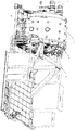
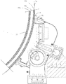
도 1은 본 발명의 코팅 장치의 전체적인 3차원 사시도이다.
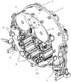
도 2는 본 발명의 코팅 장치의 내부 상세를 도시하는 단면 사시도이다.
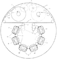
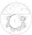
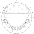
도 3은 본 발명의 코팅 장치의 주요 설계 요소만 도시하는 것으로 한정된 간이 평면 단면도이다.
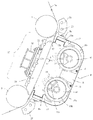
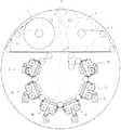
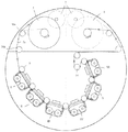
도 4는 본 발명의 증착 챔버의 하나의 기본 실시예에 대한 상세 구조를 도시하는, 도 3의 통상적인 코팅 스테이션의 개략 단면도이다.
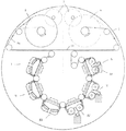
도 5는 본 발명의 증착 챔버의 추가 코팅 구조에 대한 상세를 도시하는 조합적 개략 단면도이다.
도 6은 본 발명의 증착 챔버의 다양한 코팅 구조에 대한 보편적인 드럼 및 수송 시스템 실시예를 도시하는 조합적 개략 단면도이다.
도 7은 보다 보편적인 코팅 드럼 실시예에서 완전히 구성된 본 발명의 코팅 기계의 단면도이다.
도 8은 CIGS형 박막 태양 전지용 후면 전극을 박막 포일 기판 상에 코팅하도록 구성될 때의 본 발명의 코팅 기계의 개략 단면도이다.
도 9는 CIGS형 박막 태양 전지용 흡수재 층을 박막 포일 기판 상에 코팅하도록 구성될 때의 본 발명의 코팅 기계의 개략 단면도이다.
도 10은 CIGS형 박막 태양 전지용 접합층을 박막 포일 기판 상에 코팅하도록 구성될 때의 본 발명의 코팅 기계의 개략 단면도이다.
도 11은 CIGS형 박막 태양 전지용 투명 상부 전극을 박막 포일 기판 상에 코팅하도록 구성될 때의 본 발명의 코팅 기계의 개략 단면도이다.
도 12는 웹의 코팅된 표면과의 수송 롤러 접촉을 방지하도록 구성될 때의 본 발명의 코팅 기계의 개략 단면도이다.
도 13은 코팅이 완료될 때까지 웹의 코팅된 표면과의 수송 롤러 접촉을 방지하는 대체 구조를 갖는 본 발명의 코팅 기계의 개략 단면도이다.
도 14는 본 발명의 방법을 수행하도록 프로그래밍되거나 구성되는 컴퓨터 시스템의 개략도이다.The novel features of the invention are set forth with particularity in the claims. BRIEF DESCRIPTION OF THE DRAWINGS A better understanding of the features and advantages of the present invention will be gained with reference to the following detailed description, and the accompanying drawings, which illustrate exemplary embodiments in which the principles of the invention may be utilized.
1 is an overall three-dimensional perspective view of a coating apparatus of the present invention.
2 is a cross-sectional perspective view showing the internal details of the coating apparatus of the present invention.
FIG. 3 is a simplified planar cross-sectional view defined by only showing the major design elements of the coating apparatus of the present invention.
Figure 4 is a schematic cross-sectional view of the conventional coating station of Figure 3, showing the detailed structure of one basic embodiment of the deposition chamber of the present invention.
5 is a combinational schematic cross-sectional view showing details of the additional coating structure of the deposition chamber of the present invention.
Figure 6 is a combined schematic cross-sectional view illustrating a universal drum and transport system embodiment for various coating structures of a deposition chamber of the present invention.
Figure 7 is a cross-sectional view of a coating machine of the present invention that is fully constructed in a more common coating drum embodiment.
8 is a schematic cross-sectional view of the coating machine of the present invention when it is configured to coat a back electrode for a CIGS thin film solar cell on a thin foil substrate.
9 is a schematic cross-sectional view of the coating machine of the present invention when it is configured to coat a CIGS thin film solar cell absorber layer on a thin foil substrate.
10 is a schematic cross-sectional view of the coating machine of the present invention when it is configured to coat a bonding layer for a CIGS-type thin film solar cell on a thin foil substrate.
11 is a schematic cross-sectional view of a coating machine of the present invention when it is configured to coat a transparent upper electrode for a CIGS thin film solar cell on a thin foil substrate.
Figure 12 is a schematic cross-sectional view of a coating machine of the present invention when it is configured to prevent transport roller contact with the coated surface of the web.
Figure 13 is a schematic cross-sectional view of a coating machine of the present invention having an alternative structure that prevents transport roller contact with the coated surface of the web until coating is complete.
14 is a schematic diagram of a computer system that is programmed or configured to perform the method of the present invention.
본 발명의 다양한 실시예가 본 명세서에 설명되지만, 이러한 실시예는 단지 예로서 제공된다는 것은 당업자에게 자명할 것이다. 본 발명의 범위를 벗어나지 않는 한도 내에서 다양한 수정, 변경 및 치환이 당업자에게 이루어질 수 있다. 본 명세서에 기술되는 본 발명의 실시예에 대한 다양한 대체예가 본 명세서에 기술되는 본 발명(들)의 임의의 것을 실시하는데 사용될 수 있음을 알아야 한다.While various embodiments of the present invention are described herein, it will be apparent to those skilled in the art that such embodiments are provided by way of example only. Various modifications, changes, and substitutions may be made to those skilled in the art without departing from the scope of the present invention. It should be understood that various alternatives to the embodiments of the invention described herein may be used to practice any of the invention (s) described herein.
본 명세서에 사용되는 "태양 전지"라는 용어는 전자기 방사선(또는 빛)의 에너지를 광기전(photovoltaic: PV) 효과에 의해 전기로 변환시키는 활성 물질(또는 흡수재)을 갖는 고체 상태 전기 디바이스를 지칭한다.The term "solar cell " as used herein refers to a solid state electrical device having an active material (or absorber) that converts the energy of electromagnetic radiation (or light) into electricity by a photovoltaic .
본 명세서에 사용되는 "흡수재(absorber)"라는 용어는 일반적으로, 전자기 방사선에 노출될 때 전자기 방사선의 에너지를 광기전(PV) 효과에 의해 전기로 변환시키는 광활성 재료를 지칭한다. 흡수재는 광의 선택 파장에서 전기를 발생시키도록 구성될 수 있다. 흡수재 층은 전자/전공 쌍을 발생시키도록 구성될 수 있다. 빛에 노출될 때, 흡수재는 전자/정공 쌍을 발생시킬 수 있다. 흡수재의 예로는 구리 인듐 갈륨 디셀레나이드(copper indium gallium di-selenide: CIGS) 및 구리 인듐 셀레나이드(copper indium selenide: CIS)가 비제한적으로 포함된다. 흡수재 층은 도핑된 n-형 또는 p-형일 수 있다. 일부 흡수재는 추가 도핑이 전혀 없는 n-형 또는 p-형이다. 예를 들어, 형성된 CIGS는 p-형일 수 있으며, 추가 p-형 도핑을 일절 요구하지 않을 수 있다. 일부 경우에, 흡수재 층(예를 들면, 실리콘 흡수재 층)을 형성할 때는, 흡수재 층에 n-형 또는 p-형 도펀트(dopant)를 통합하기 위해 n-형 또는 p-형 도펀트의 전구체가 도입된다. 대안으로서, 흡수재 층의 형성 이후에, n-형 또는 p-형 도펀트가 이온 주입에 이어지는 어닐링에 의해서 흡수재 층에 도입될 수 있다. 일부 상황(예를 들면, CIGS)에서는, 흡수재 층에 나트륨을 포함하도록 나트륨 전구체가 흡수재 층에 제공된다.The term "absorber " as used herein generally refers to a photoactive material that converts the energy of electromagnetic radiation to electricity by photovoltaic (PV) effects when exposed to electromagnetic radiation. The absorber may be configured to generate electricity at a selected wavelength of light. The absorber layer may be configured to generate an electron / hole pair. When exposed to light, the absorber can generate electron / hole pairs. Examples of the absorber include, but are not limited to, copper indium gallium di-selenide (CIGS) and copper indium selenide (CIS). The absorber layer may be doped n-type or p-type. Some absorbers are n-type or p-type with no additional doping. For example, the CIGS formed may be p-type and may not require any additional p-type doping. In some cases, when forming the absorber layer (for example, the silicon absorber layer), a precursor of the n-type or p-type dopant is introduced to integrate the n- or p-type dopant into the absorber layer do. Alternatively, after formation of the absorber layer, an n-type or p-type dopant may be introduced into the absorber layer by annealing followed by ion implantation. In some situations (e.g., CIGS), a sodium precursor is provided in the absorber layer to include sodium in the absorber layer.
본 명세서에 사용되는 "광기전 모듈" 또는 "솔라 모듈"이라는 용어는 하나 이상의 PV 전지의 패키지 어레이를 지칭한다. PV 모듈(본 명세서에서 "모듈"로도 지칭됨)은 상업 용도 및 거주 용도 등에서 전기를 발생 및 공급하기 위한 대형 광기전 시스템의 부품으로서 사용될 수 있다. PV 모듈은 하나 이상의 PV 전지를 갖는 지지 구조물을 구비할 수 있다. 일부 실시예에서, PV 모듈은 예를 들어 인터커넥트의 도움으로 직렬로 상호연결될 수 있는 복수의 PV 전지를 구비한다. PV 어레이는 복수의 PV 모듈을 구비할 수 있다.The term " photovoltaic module "or" solar module ", as used herein, refers to a package array of one or more PV cells. A PV module (also referred to herein as a "module") can be used as a component of a large photovoltaic system for generating and supplying electricity in commercial and residential applications. The PV module may have a support structure with one or more PV cells. In some embodiments, the PV modules have a plurality of PV cells that can be interconnected in series with the aid of, for example, an interconnect. The PV array may have a plurality of PV modules.
본 명세서에 사용되는 "n-형"은 일반적으로 n-형 도펀트로 화학적으로 도핑되는("도핑된") 재료를 지칭한다. 예를 들어, 실리콘은 인 또는 비소를 사용하여 도핑된 n-형일 수 있다."N-type" as used herein generally refers to a material that is chemically doped ("doped") with an n-type dopant. For example, silicon may be n-type doped with phosphorous or arsenic.
본 명세서에 사용되는 "p-형"은 일반적으로 p-형 도펀트로 도핑되는 재료를 지칭한다. 예를 들어, 실리콘은 붕소 또는 알루미늄을 사용하여 도핑된 p-형일 수 있다.As used herein, "p-type" refers to materials that are generally doped with a p-type dopant. For example, silicon may be p-type doped with boron or aluminum.
본 명세서에 사용되는 "층"이라는 용어는 일반적으로 기판 상의 원자 또는 분자 층을 지칭한다. 일부 경우에, 층은 단수 또는 복수의 에피택셜 층을 구비한다. 층은 막 또는 박막을 구비할 수 있다. 일부 상황에서, 층은 소정 디바이스 기능을 수행하는 디바이스(예를 들면, 발광 다이오드)의 구성 부품이며, 예를 들면 광을 발생(또는 방출)하도록 구성되는 활성층이다. 층은 일반적으로 약 1 단층(monolayer: ML) 내지 수십 단층, 수백 단층, 수천 단층, 수백만 단층, 수십억 단층, 수조 단층 이상의 두께를 갖는다. 일 예로서, 층은 1 단층보다 큰 두께를 갖는 다층 구조이다. 또한, 층은 다중 재료 층(또는 서브-층)을 구비할 수 있다. 일 예에서, 다중 양자 웰(quantum well) 활성층은 다중 웰 및 배리어 층을 구비한다. 층은 복수의 서브-층을 구비할 수 있다. 예를 들어, 활성층은 배리어 서브-층 및 웰 서브-층을 구비할 수 있다.The term "layer" as used herein generally refers to an atomic or molecular layer on a substrate. In some cases, the layer comprises single or multiple epitaxial layers. The layer may comprise a film or a thin film. In some situations, the layer is a component of a device (e.g., a light emitting diode) that performs a given device function and is, for example, an active layer configured to emit (or emit) light. The layer generally has about one monolayer (ML) to several tens of monolayers, several hundred monolayers, thousands of monolayers, millions of monolayers, several billion monolayers, and a monolayer or more monolayer. As an example, the layer is a multilayer structure having a thickness greater than one monolayer. In addition, the layer may have a multi-material layer (or sub-layer). In one example, a multiple quantum well active layer has multiple wells and a barrier layer. The layer may have a plurality of sub-layers. For example, the active layer may have a barrier sub-layer and a well sub-layer.
본 명세서에 사용되는 "기판"이라는 용어는 일반적으로, 그 위에 층, 막 또는 박막이 요구되는 임의의 피가공물을 지칭한다. 기판은 실리콘, 게르마늄, 실리카, 사파이어, 산화 아연, 탄소(예를 들면, 그래핀), SiC, AlN, GaN, 스피넬, 코팅된 실리콘, 실리콘 온 옥사이드, 실리콘 카바이드 온 옥사이드(silicon carbide on oxide), 유리, 질화 갈륨, 질화 인듐, 이산화티탄 및 질화 알루미늄, 세라믹 재료(예를 들면, 알루미나, AlN), 금속 재료(예를 들면, 스테인레스 스틸, 텅스텐, 티탄, 구리, 알루미늄), 폴리머 재료 및 그 조합(또는 합금)을 비제한적으로 포함한다.The term "substrate" as used herein generally refers to any workpiece on which a layer, film or film is desired. The substrate may be silicon, germanium, silica, sapphire, zinc oxide, carbon (e.g., graphene), SiC, AlN, GaN, spinel, coated silicon, silicon onoxide, silicon carbide on oxide, (E.g., glass, gallium nitride, indium nitride, titanium dioxide and aluminum nitride, ceramic materials such as alumina and AlN), metal materials (e.g., stainless steel, tungsten, titanium, copper and aluminum) (Or alloys).
본 명세서에 사용되는 "인접한" 또는 "에 인접한(adjacent to)"이라는 용어는 '에 이웃하는', '붙어있는', '접촉하는' 및 '에 근접하는'을 포함한다. 일부 경우에, 인접한 부품은 하나 이상의 중개 층에 의해 상호 분리된다. 예를 들어, 하나 이상의 중개 층은 약 10 마이크로미터("미크론"), 1 미크론, 500 나노미터("nm"), 100 nm, 50 nm, 10 nm, 1 nm 또는 그 이하보다 작은 두께를 가질 수 있다. 일 예에서, 제 1 층이 제 2 층과 직접 접촉할 때 제 1 층은 제 2 층에 인접한다. 다른 예에서, 제 1 층이 제 3 층에 의해 제 2 층으로부터 분리될 때 제 1 층은 제 2 층에 인접한다.As used herein, the terms "adjacent" or " adjacent to "include " neighboring ", " attached, " In some cases, adjacent components are separated from each other by one or more mediation layers. For example, one or more intermediate layers may have a thickness of less than about 10 micrometers ("micron"), 1 micron, 500 nanometers ("nm"), 100 nm, 50 nm, 10 nm, 1 nm, . In one example, the first layer is adjacent to the second layer when the first layer is in direct contact with the second layer. In another example, when the first layer is separated from the second layer by the third layer, the first layer is adjacent to the second layer.
본 명세서에 사용되는 "반응 공간"이라는 용어는 일반적으로, 기판에 인접하여 재료 층, 막 또는 박막을 증착하기에 적합한 임의의 환경, 또는 재료 층, 막 또는 박막의 물리적 특징의 측정을 지칭한다. 반응 공간은 재료 공급원을 구비하거나 재료 공급원에 유체적으로 결합될 수 있다. 일 예에서, 반응 공간은 반응 챔버(본 명세서에서 "챔버"로도 지칭됨)를 구비한다. 다른 예에서, 반응 공간은 복수의 챔버를 갖는 시스템 내에 챔버를 구비한다. 반응 공간은 복수의 유체적으로 분리된 챔버를 갖는 시스템 내에 챔버를 구비할 수 있다. 태양 전지를 형성하기 위한 시스템은 다중 반응 공간을 구비할 수 있다. 반응 공간은 상호 유체적으로 분리될 수 있다. 일부 반응 공간은 기판 또는 기판에 인접하여 형성된 층, 막 또는 박막에 대해 측정을 수행하기에 적합할 수 있다.The term "reaction space" as used herein generally refers to any environment suitable for depositing a layer of material, film or film, adjacent to a substrate, or a measurement of the physical characteristics of a material layer, film or film. The reaction space may have a material source or may be fluidly coupled to a material source. In one example, the reaction space has a reaction chamber (also referred to herein as a "chamber"). In another example, the reaction space has a chamber within a system having a plurality of chambers. The reaction space may comprise a chamber within a system having a plurality of fluidly separated chambers. The system for forming the solar cell may have multiple reaction spaces. The reaction spaces can be separated fluidly from each other. Some reaction spaces may be suitable for performing measurements on a substrate, a layer, a film or a thin film formed adjacent to the substrate.
본 명세서에 사용되는 "유체 공간"이라는 용어는 일반적으로, 유체를 수용하거나 유체를 유체 유동 경로를 따라서 인도할 수 있는 임의의 환경을 지칭한다. 일부 경우에, 유체 공간은 반응 공간이다.The term "fluid space" as used herein generally refers to any environment capable of receiving a fluid or delivering it along a fluid flow path. In some cases, the fluid space is a reaction space.
본 명세서에 사용되는 "플럭스"라는 용어는 일반적으로 재료의 유동을 지칭한다. 일부 경우에 플럭스는 단위 면적당 재료의 유량이다.The term "flux" as used herein generally refers to the flow of material. In some cases flux is the flow rate of material per unit area.
스퍼터링Sputtering 시스템 system
본 발명의 일 양태는 가요성 기판 상에 박막 태양 전지를 증착하기 위한 증착 시스템을 제공한다. 이러한 시스템은 구리 인듐 갈륨 디셀레나이드(CIGS), 구리 인듐 알루미늄 디셀레나이드(copper indium aluminum diselenide: CIAS), 구리 아연 주석 디설파이드/셀레나이드(copper zinc tin disulfide/selenide: CZTS), 구리 인듐 디셀레나이드(CIS), 카드뮴 텔루르("카드뮴 텔루라이드"), 또는 카드뮴 아연 텔루르로 형성된 흡수재를 포함하는 태양 전지의 형성에 사용하기 위해 채용될 수 있다.One aspect of the present invention provides a deposition system for depositing a thin film solar cell on a flexible substrate. Such systems include copper indium gallium diselenide (CIGS), copper indium aluminum diselenide (CIAS), copper zinc tin disulfide / selenide (CZTS), copper indium diselenide (CIS), cadmium tellurium ("cadmium telluride"), or cadmium zinc telluride.
가요성 기판 상에 태양 전지를 증착하기 위한 시스템은 그 외부 환경으로부터 유체적으로 격리되는 유체 공간을 포함하는 인클로저, 및 유체 공간 내의 복수의 증착 챔버를 포함한다. 복수의 증착 챔버 중 적어도 하나의 증착 챔버는 하나 이상의 타겟 재료의 재료 플럭스를 복수의 증착 챔버 중 상기 적어도 하나의 증착 챔버 내에 배치된 가요성 기판의 부분 쪽으로 인도하는 마그네트론 스퍼터링 조립체(또는 장치)(본 명세서에서 "마그네트론"으로도 지칭됨)를 포함한다. 상기 시스템은 인클로저의 유체 공간 내에 적어도 하나의 가이드 롤러를 추가로 구비할 수 있다. 가이드 롤러는 가요성 기판을 복수의 증착 챔버 중 소정의 증착 챔버로 또는 그로부터 멀리 인도하도록 구성될 수 있다.A system for depositing a solar cell on a flexible substrate includes an enclosure comprising a fluid space fluidly isolated from its external environment, and a plurality of deposition chambers in a fluid space. At least one of the plurality of deposition chambers includes a magnetron sputtering assembly (or device) for directing material fluxes of the at least one target material to a portion of the plurality of deposition chambers disposed within the at least one deposition chamber Quot; magnetron "in the specification). The system may further include at least one guide roller in the fluid space of the enclosure. The guide rollers may be configured to guide the flexible substrate away from or to a predetermined deposition chamber of the plurality of deposition chambers.
증착 챔버는 반응 공간을 수용하는 하나 이상의 벽을 구비할 수 있다. 증착 챔버는 재료 플럭스가 가요성 기판과 접촉할 수 있게 하는 개구를 가질 수 있다.The deposition chamber may have one or more walls to receive the reaction space. The deposition chamber may have openings that allow the material flux to contact the flexible substrate.
복수의 증착 챔버 중의 제 1 증착 챔버와 제 2 증착 챔버 사이에 가이드 롤러가 배치될 수 있다. 가이드 롤러는 가요성 기판을 제 1 증착 챔버로부터 제 2 증착 챔버로 안내하거나 인도하기 위해 사용될 수 있다. 가이드 롤러는 제 1 및 제 2 증착 챔버로부터 유체적으로 격리될 수 있다. 가이드 롤러는 유체 공간 내에 배치될 수 있다.A guide roller may be disposed between the first deposition chamber and the second deposition chamber of the plurality of deposition chambers. The guide rollers may be used to guide or guide the flexible substrate from the first deposition chamber to the second deposition chamber. The guide rollers may be fluidly isolated from the first and second deposition chambers. The guide rollers may be disposed in the fluid space.
가이드 롤러는 가요성 기판을 기판 인출 롤러로부터 증착 챔버로, 증착 챔버로부터 기판 권취 롤러로, 또는 복수의 증착 챔버 중에서 하나의 증착 챔버로부터 다른 증착 챔버로 인도하거나 안내할 수 있다. 인출 롤러는 하나 이상의 증착 챔버 내로 인도되는 가요성 기판의 롤을 구비할 수 있다. 기판은 인출 롤러의 스풀(spool) 주위에 래핑(또는 권선)될 수 있다. 막 증착 이후, 기판은 권취 롤러 내로 인도된다. 기판은 권취 롤러의 스풀 내로 인도되어 스풀 주위에 래핑(또는 권선)될 수 있다.The guide rollers may guide or guide the flexible substrate from the substrate withdrawal roller to the deposition chamber, from the deposition chamber to the substrate take-up roller, or from one deposition chamber to the other of the plurality of deposition chambers. The drawing roller may have a roll of a flexible substrate that is directed into the at least one deposition chamber. The substrate can be wrapped (or wound) around a spool of the draw-out roller. After the film deposition, the substrate is led into the winding roller. The substrate may be led into the spool of the take-up roller and wrapped around (or wound around) the spool.
가이드 롤러는 증착 챔버로부터의 가스 또는 증기가 롤러와 접촉하는 것을 최소화하거나 방지하는 퍼지(purge) 가스 또는 기타 배경 가스의 도움으로 제 1 및 제 2 증착 챔버로부터 유체적으로 격리될 수 있다.The guide rollers may be fluidically isolated from the first and second deposition chambers with the aid of purge gas or other background gas that minimizes or prevents gas or vapor from the deposition chamber from contacting the rollers.
시스템은 적어도 1, 2, 3, 4, 5, 6, 7, 8, 9, 10, 20, 30, 40, 50, 100 또는 1000 개의 가이드 롤러를 구비할 수 있다. 시스템은 인클로저 내의 개별 증착 챔버 사이에 적어도 1, 2, 3, 4, 5, 6, 7, 8, 9, 10, 20, 30, 40, 50 또는 100 개의 가이드 롤러를 구비할 수 있다.The system may include at least 1, 2, 3, 4, 5, 6, 7, 8, 9, 10, 20, 30, 40, 50, 100 or 1000 guide rollers. The system may include at least 1, 2, 3, 4, 5, 6, 7, 8, 9, 10, 20, 30, 40, 50 or 100 guide rollers between the individual deposition chambers in the enclosure.
일부 상황에서, 가이드 롤러의 사용은 가요성 기판을 증착 챔버 중에서 인도하기 위한 드럼에 대한 필요성을 배제할 수 있다. 이는 시스템 복잡성을 최소화하는데 유리하게 도움이 될 수 있으며, 이것은 비용을 최소화하는데 도움이 될 수 있다. 일부 예에서, 시스템은 드럼이 없다(즉, 드럼을 포함하지 않는다). 일부 실시예에서, 롤러의 사용은 (드럼과 대조적으로) 증착 챔버(및 각각의 증착 챔버 내의 부분 또는 기판)를 결합해제(예를 들면, 열적으로 결합해제)시킬 수 있으며, 이는 다양한 이점 및 장점을 가능하게 할 수 있다. 예를 들어, 롤러의 사용은 드럼과 대조적으로, 예를 들어 (1) 보다 신속한 태양 전지 제조를 가능하게 하는, 기판의 앞면과 뒷면의 동시 코팅, (2) 보다 신속한 가열/냉각 및 보다 높은 가열 속도, 및 (3) 상이한 온도 및 가열/냉각 속도를 제공할 수 있는, 다양한 증착 챔버에서의 독립적 가열을 가능하게 할 수 있다.In some situations, the use of a guide roller may preclude the need for a drum to deliver a flexible substrate in a deposition chamber. This can be beneficially beneficial in minimizing system complexity, which can help to minimize cost. In some instances, the system has no drum (i.e., does not include a drum). In some embodiments, the use of the rollers can disengage (e.g., thermally disengage) the deposition chamber (and the portion or substrate within each deposition chamber) (as opposed to the drum) . ≪ / RTI > For example, the use of rollers may be advantageous, for example, in contrast to drums, such as (1) simultaneous coating of the front and back sides of the substrate, which allows for faster solar cell fabrication, (2) (3) independent heating in various deposition chambers, which can provide different temperatures and heating / cooling rates.
일부 예에서, 인클로저 내의 증착 챔버는 인클로저를 충전하는 퍼지 가스 또는 기타 배경 가스의 도움으로 상호 유체적으로 격리될 수 있다. 대안적으로 또는 추가적으로, 인클로저는 증착 챔버로부터 유체 공간 내로 유동하는 가스 또는 증기를 펌핑 방출하는 펌핑 시스템을 구비할 수 있다.In some instances, the deposition chambers in the enclosure may be fluidly isolated from each other with the aid of a purge gas or other background gas filling the enclosure. Alternatively or additionally, the enclosure may include a pumping system for pumping and discharging gas or vapor flowing into the fluid space from the deposition chamber.
펌핑 시스템은 터보분자("터보") 펌프, 확산 펌프, 이온 펌프, 저온("cryo") 펌프, 및 기계식 펌프 중 하나 이상과 같은, 하나 이상의 진공 펌프를 구비할 수 있다. 펌프는 하나 이상의 보조 펌프를 구비할 수 있다. 예를 들어, 터보 펌프는 기계식 펌프에 의해 보조될 수 있다.The pumping system may include one or more vacuum pumps, such as one or more of a turbo molecular ("turbo") pump, a diffusion pump, an ion pump, a low temperature ("cryo" The pump may have one or more auxiliary pumps. For example, a turbo pump can be assisted by a mechanical pump.
시스템은 인클로저 내에 기판 인출 롤러(본 명세서에서 "인출 롤러"로도 지칭됨) 및 기판 권취 롤러(본 명세서에서 "권취 롤러"로도 지칭됨)를 추가로 구비할 수 있다. 사용 중에, 가요성 기판은 인출 롤러로부터 복수의 증착 챔버의 각각을 통해서 권취 롤러로 인도된다.The system may further include a substrate draw-out roller (also referred to herein as a "draw-out roller") and a substrate take-up roller (also referred to herein as a "take- up roller") within the enclosure. In use, the flexible substrate is guided from the pull-out rollers to each of the winding rollers through each of the plurality of deposition chambers.
시스템은 마그네트론 스퍼터링 조립체(또는 장치)를 구비하지 않는 하나 이상의 추가 증착 챔버를 추가로 구비할 수 있다. 가요성 기판은 인출 롤러로부터 하나 이상의 추가 증착 챔버를 통해서 권취 롤러로 인도될 수 있다.The system may further include one or more additional deposition chambers that do not have a magnetron sputtering assembly (or device). The flexible substrate may be led from the drawing roller to the winding roller through one or more additional deposition chambers.
인클로저는 다양한 형상과 크기를 가질 수 있다. 일부 예에서, 인클로저는 원형, 삼각형, 정방형 또는 장방형 단면을 갖는다. 일 예에서, 인클로저는 대체로 원통형 형상이다.The enclosure may have various shapes and sizes. In some examples, the enclosure has a circular, triangular, square or rectangular cross-section. In one example, the enclosure is generally cylindrical in shape.
인클로저는 스테인레스 스틸과 같은 금속 재료로 형성될 수 있다. 인클로저는 약 1 피트(30.48 cm) 내지 100 피트(30.48 m) 또는 1 피트 내지 10 피트(3.048 m)의 길이, 및 약 1 피트 내지 100 피트 또는 1 피트 내지 10 피트의 직경(또는 폭)을 가질 수 있다. 인클로저는 시스템 작동 중에 인클로저를 밀봉하는 캡을 구비할 수 있다. 유체 공간은 유체 공간과 유체 연통하는 펌핑 시스템의 도움으로 소정의 압력으로 유지될 수 있다.The enclosure may be formed of a metallic material such as stainless steel. The enclosure may have a diameter of about 1 foot (30.48 cm) to 100 feet (30.48 m) or a length of 1 to 10 feet (3.048 m), and a diameter (or width) of about 1 foot to 100 feet or 1 foot to 10 feet . The enclosure may include a cap to seal the enclosure during system operation. The fluid space may be maintained at a predetermined pressure with the aid of a pumping system in fluid communication with the fluid space.
예를 들어, 인클로저는 진공 하에 또는 제어된 환경에서 유지될 수 있다. 인클로저는 본 명세서의 다른 곳에 기재되어 있는 펌핑 시스템의 도움으로 진공 하에 유지될 수 있다. 일부 상황에서, 인클로저는 가스(예를 들면, Ar, He, Ne, N2)로 퍼지된다.For example, the enclosure may be maintained under vacuum or in a controlled environment. The enclosure can be kept under vacuum with the aid of the pumping system described elsewhere herein. In some situations, the enclosure is purged with a gas (e.g., Ar, He, Ne, N 2 ).
일부 예에서, 인클로저는 펌핑 시스템의 도움으로 진공 하에 유지된다. 인클로저는 약 100 토르(torr), 1 토르, 10-1 토르, 10-2 토르, 10-3 토르, 10-4 토르, 10-5 토르, 10-6 토르, 10-7 토르, 또는 10-8 토르 이하의 압력으로 유지될 수 있다. 대안으로서, 인클로저는 인클로저 외부 환경의 압력에 대해 상승되는 압력으로 유지된다. 예를 들어, 인클로저는 약 10-6 토르, 10-5 토르, 10-4 토르, 10-3 토르, 10-2 토르, 10-1 토르, 1 토르, 100 토르 또는 1000 토르 이상의 압력으로 유지될 수 있다.In some instances, the enclosure is kept under vacuum with the aid of a pumping system. The enclosure is about 100 Torr (torr), 1 Torr, 10 -1 torr and 10 -2 torr, 10 -3 Torr, 10-4 Torr, 10 -5 Torr, 10-6 Torr, 10-7 Torr, or 10 - It can be maintained at a pressure of 8 Torr or less. Alternatively, the enclosure is maintained at a pressure that is elevated relative to the pressure in the enclosure's external environment. For example, the enclosure may have a height of about 10 -6 Torr, 10 -5 Torr, 10 -4 Torr, 10 -3 Torr, 10 -2 Torr, 10 -1 Torr, 1 Tor, 100 Torr or 1000 Torr or higher.
가요성 기판은 기판을 지지하는 기판 웹의 도움으로 하나의 증착 챔버에서 다른 증착 챔버로 인도될 수 있다. 기판 웹은 기판을 보유하도록 구성될 수 있다. 일 예에서, 기판 웹은 메쉬이다.The flexible substrate may be delivered from one deposition chamber to another with the aid of a substrate web supporting the substrate. The substrate web may be configured to hold the substrate. In one example, the substrate web is a mesh.
가요성 기판은 다양한 형태의 재료로 형성될 수 있다. 일부 경우에, 가요성 기판은 전기 전도성 재료로 형성된다. 일 예에서, 가요성 기판은 스테인레스 스틸 기판이다. 다른 예에서, 가요성 기판은 알루미늄 기판이다. 다른 예에서, 가요성 기판은 폴리머 재료로 형성된다.The flexible substrate may be formed of various types of materials. In some cases, the flexible substrate is formed of an electrically conductive material. In one example, the flexible substrate is a stainless steel substrate. In another example, the flexible substrate is an aluminum substrate. In another example, the flexible substrate is formed of a polymeric material.
시스템의 복수의 챔버의 개별 챔버는 가요성 기판이 개별 챔버에 진입할 수 있게 하는 제 1 개구 및 웹이 개별 챔버에서 퇴출될 수 있게 하는 제 2 개구를 구비할 수 있다. 제 1 및 제 2 개구는 가요성 기판이 이들 개구를 통과할 수 있도록 구성된다. 제 1 및 제 2 개구는 다양한 형상과 크기를 가질 수 있다. 일부 예에서, 개구는 슬릿이다. 시스템은 제 1 개구에 인접한 제 1 롤러 및 제 2 개구에 인접한 제 2 롤러를 구비할 수 있다. 제 1 롤러는 가요성 기판을 개별 챔버 내로 인도하도록 구성되며, 제 2 롤러는 가요성 기판을 개별 챔버 밖으로 인도하도록 구성된다.The individual chambers of the plurality of chambers of the system may have a first opening that allows the flexible substrate to enter the individual chambers and a second opening that allows the web to exit the individual chambers. The first and second openings are configured such that the flexible substrate can pass through these openings. The first and second openings can have various shapes and sizes. In some examples, the aperture is a slit. The system may include a first roller adjacent the first opening and a second roller adjacent the second opening. The first roller is configured to guide the flexible substrate into the individual chambers and the second roller is configured to guide the flexible substrate out of the individual chambers.
복수의 증착 챔버는 복수의 마그네트론 스퍼터링 조립체를 구비할 수 있다. 복수의 증착 챔버의 개별 증착 챔버에 개별 마그네트론 스퍼터링 조립체(또는 장치)가 배치될 수 있다. 일부 경우에, 증착 챔버는 복수의 마그네트론 스퍼터링 조립체를 구비한다. 예를 들어, 증착 챔버는 적어도 1, 2, 3, 4, 5, 6, 7, 8, 9, 10, 20, 30, 40, 50 또는 100 개의 마그네트론 스퍼터링 조립체를 구비할 수 있으며, 각각의 마그네트론 스퍼터링 조립체는 하나 이상의 타겟 재료의 플럭스를 제공하도록 구성될 수 있다. 마그네트론 스퍼터링 조립체는 회전식 마그네트론 또는 평판 마그네트론일 수 있다. 평판 마그네트론은 수평 구조를 가질 수 있다.The plurality of deposition chambers may have a plurality of magnetron sputtering assemblies. Individual magnetron sputtering assemblies (or devices) may be disposed in individual deposition chambers of a plurality of deposition chambers. In some cases, the deposition chamber has a plurality of magnetron sputtering assemblies. For example, the deposition chamber may have at least 1, 2, 3, 4, 5, 6, 7, 8, 9, 10, 20, 30, 40, 50 or 100 magnetron sputtering assemblies, The sputtering assembly may be configured to provide a flux of one or more target materials. The magnetron sputtering assembly may be a rotary magnetron or a flat magnetron. The flat plate magnetron may have a horizontal structure.
시스템은 하나 이상의 증착 챔버를 구비할 수 있다. 일부 경우에, 시스템은 적어도 1, 2, 3, 4, 5, 6, 7, 8, 9, 10, 20, 30, 40, 50 또는 100 개의 증착 챔버를 수용하는 인클로저를 포함한다. 시스템은 기판을 제공(예를 들면, 송출)하기 위한 기판 인출 롤러, 및 시스템의 증착 챔버에서의 하나 이상의 재료 층의 적층 이후 기판을 권취하기 위한 기판 권취 롤러를 구비할 수 있다.The system may have one or more deposition chambers. In some cases, the system includes an enclosure that accommodates at least 1, 2, 3, 4, 5, 6, 7, 8, 9, 10, 20, 30, 40, 50 or 100 deposition chambers. The system may include a substrate withdrawal roller for providing (e.g., dispensing) a substrate, and a substrate take-up roller for winding the substrate after deposition of one or more material layers in the deposition chamber of the system.
태양 전지 층은 순차적으로, 즉 하나 뒤에 다른 하나가 증착될 수 있다. 이는 기판의 일부를 증착 챔버 내에 순차적으로 인도함으로써 이루어질 수 있다.The solar cell layers can be deposited one after another, one after the other. This may be accomplished by sequentially delivering a portion of the substrate into the deposition chamber.
시스템은 일부 경우에, 복수의 마그네트론 스퍼터링 조립체를 포함하는 적어도 하나의 증착 챔버를 구비한다. 일부 예에서, 적어도 하나의 증착 챔버는 복수의 평판 마그네트론 스퍼터링 조립체, 복수의 회전식 마그네트론 스퍼터링 조립체, 또는 평판 및 회전식 마그네트론 스퍼터링 조립체의 조합을 구비한다.The system comprises in some cases at least one deposition chamber comprising a plurality of magnetron sputtering assemblies. In some examples, at least one of the deposition chambers has a combination of a plurality of flat plate magnetron sputtering assemblies, a plurality of rotating magnetron sputtering assemblies, or a flat plate and rotary magnetron sputtering assembly.
일부 예에서, 시스템은 기판에 인접하여 실리콘, CIGS, CIS, CIAS, CZTS, CdTe 또는 CdZnTe 흡수재를 형성하도록 구성된다. 이러한 경우에, 시스템의 증착 챔버는 구리, 인듐 및 갈륨의 재료 플럭스를 제공하도록 구성될 수 있다. 증착 챔버는 일부 경우에 다른 재료 플럭스와 별도로 셀레늄의 재료 플럭스를 제공할 수 있다.In some examples, the system is configured to form a silicon, CIGS, CIS, CIAS, CZTS, CdTe, or CdZnTe absorber adjacent to the substrate. In this case, the deposition chamber of the system may be configured to provide a flux of material of copper, indium and gallium. The deposition chamber may in some cases provide material fluxes of selenium apart from other material fluxes.
사용 중에, 가요성 기판은 개별 증착 챔버 내로 인도되며, 증착 챔버 내에 있는 가요성 기판의 부분은 하나 이상의 타겟 재료의 재료 플럭스에 노출된다. 가요성 기판은 약 0.001 meters(m)/minute(min), 0.01 m/min, 0.1 m/min, 1 m/min, 10 m/min 또는 100 m/min 이상의 속도와 같은 연속 속도로 또는 대안으로서 일련의 단계적으로 증착 챔버를 통과할 수 있다.In use, the flexible substrate is led into a separate deposition chamber, and a portion of the flexible substrate within the deposition chamber is exposed to the material flux of one or more target materials. The flexible substrate may be provided at a continuous rate such as a speed of about 0.001 meters (m) / minute, 0.01 m / min, 0.1 m / min, 1 m / min, 10 m / min or 100 m / And can pass through the deposition chamber in a series of steps.
하나 이상의 마그네트론 스퍼터링 조립체는 액체 타겟으로부터 재료 플럭스를 제공하도록 구성될 수 있다. 일부 상황에서, 시스템의 복수의 증착 챔버의 적어도 서브세트의 적어도 하나는 평판 마그네트론 스퍼터링 장치에 인접한 회전식 마그네트론 스퍼터링 장치를 포함하는 마그네트론 스퍼터링 조립체, 및 회전식 마그네트론 스퍼터링 장치와 평판 마그네트론 스퍼터링 장치 사이에 서브-챔버를 형성하는 하나 이상의 실드를 포함한다. 평판 마그네트론 스퍼터링 장치는 제 1 재료를 갖는 액체 타겟을 수용하고 제 1 재료를 갖는 재료 플럭스를 회전식 마그네트론 스퍼터링 장치를 향해 제공하도록 구성될 수 있다. 회전식 마그네트론 스퍼터링 장치는 제 2 재료를 갖는 고체 타겟을 평판 마그네트론 스퍼터링 장치에 대해 회전시키고 제 1 및 제 2 재료를 갖는 재료 플럭스를 가요성 기판을 향해서 제공하도록 구성될 수 있다. 제 1 재료는 제 2 재료의 제 2 융점보다 낮은 제 1 융점을 가질 수 있다. 일 예에서, 상기 제 1 재료는 갈륨이고 상기 제 2 재료는 인듐이다. 평판 마그네트론 스퍼터링 장치는 서브-챔버에 제 1 재료의 플럭스를 제공하도록 구성될 수 있다.The one or more magnetron sputtering assemblies may be configured to provide material flux from the liquid target. In some situations, at least one of at least a subset of the plurality of deposition chambers of the system comprises a magnetron sputtering assembly comprising a rotating magnetron sputtering device adjacent to a flat magnetron sputtering device, and a magnetron sputtering assembly between the magnetron sputtering device and the flat magnetron sputtering device, Lt; RTI ID = 0.0 > a < / RTI > A flat plate magnetron sputtering apparatus can be configured to receive a liquid target having a first material and to provide a material flux having a first material toward the rotating magnetron sputtering apparatus. A rotary magnetron sputtering device can be configured to rotate a solid target having a second material relative to a flat-plate magnetron sputtering device and to provide a flux of material with the first and second materials toward the flexible substrate. The first material may have a first melting point lower than the second melting point of the second material. In one example, the first material is gallium and the second material is indium. A flat-plate magnetron sputtering device may be configured to provide a flux of the first material to the sub-chamber.
일부 경우에, 상기 평판 마그네트론 스퍼터링 장치에 인접하여 다른 평판 마그네트론 스퍼터링 장치가 제공될 수 있다. 다른 평판 마그네트론 스퍼터링 장치는 서브-챔버에 제 3 재료의 플럭스를 제공하도록 구성될 수 있다. 제 3 재료의 플럭스는 회전식 마그네트론 스퍼터링 장치를 향해서 인도될 수 있다.In some cases, another flat plate magnetron sputtering apparatus may be provided adjacent to the flat plate magnetron sputtering apparatus. Other flat-plate magnetron sputtering devices can be configured to provide a flux of the third material to the sub-chamber. The flux of the third material may be directed towards the rotating magnetron sputtering device.
회전식 마그네트론 스퍼터링 장치의 형상은 적어도 부분적으로 원통형일 수 있다. 일부 경우에, 회전식 마그네트론 스퍼터링 장치는 실질적으로 원통형의 형상이다. 평판 마그네트론 스퍼터링 장치는 마그네트론 스퍼터링 장치 보디(body)에 인접하는 배킹 플레이트(backing plate)를 구비할 수 있다. 마그네트론 스퍼터링 장치 보디는 하나 이상의 자석을 구비할 수 있으며, 배킹 플레이트는 액체 타겟을 보유하도록 구성된다.The shape of the rotating magnetron sputtering device may be at least partially cylindrical. In some cases, the rotary magnetron sputtering apparatus is of a substantially cylindrical shape. The flat plate magnetron sputtering apparatus may have a backing plate adjacent to the magnetron sputtering apparatus body. The magnetron sputtering device body may include one or more magnets, and the backing plate is configured to hold a liquid target.
일부 경우에, 회전식 마그네트론 스퍼터링 장치는 고체 타겟을 평판 마그네트론 스퍼터링 장치에 대해 회전시키도록 구성된 지지 부재를 포함할 수 있다. 평판 마그네트론 스퍼터링 장치는 제 3 재료를 갖는 다른 액체를 수용하도록 구성될 수 있다.In some cases, a rotary magnetron sputtering apparatus may comprise a support member configured to rotate the solid target relative to the flat plate magnetron sputtering apparatus. A flat-plate magnetron sputtering apparatus can be configured to receive another liquid having a third material.
증착 챔버는 다중 마그네트론 스퍼터링 조립체를 구비할 수 있다. 일부 경우에, 증착 챔버의 개별 마그네트론 스퍼터링 조립체는 가요성 기판을 향하여 재료 플럭스를 제공하도록 구성될 수 있다.The deposition chamber may comprise a multi-magnetron sputtering assembly. In some cases, the individual magnetron sputtering assemblies of the deposition chamber may be configured to provide material flux toward the flexible substrate.
마그네트론 스퍼터링 조립체는 증착 챔버의 서브-챔버(즉, 증착 챔버 내의 챔버 또는 인클로저) 내에 배치될 수 있다. 일 예에서, 마그네트론 스퍼터링 조립체는 기판을 마그네트론 스퍼터링 조립체로부터의 재료 플럭스에 노출시키도록 구성된 개구를 갖는 서브-챔버 내에 봉입된다.The magnetron sputtering assembly may be disposed within a sub-chamber of the deposition chamber (i. E., A chamber or enclosure within the deposition chamber). In one example, the magnetron sputtering assembly is enclosed in a sub-chamber having an opening configured to expose the substrate to a material flux from the magnetron sputtering assembly.
증착 챔버는 기타 재료의 공급원을 구비할 수 있다. 이러한 기타 재료 공급원은 마그네트론 스퍼터링 조립체 또는 다른 형태의 증착 장치일 수 있다. 예를 들어, 시스템은 마그네트론 스퍼터링 장치를 구비하지 않는 하나 이상의 추가 증착 챔버를 구비할 수 있다. 일부 경우에, 재료 공급원은 그 재료를 함유하는 액체와 유체 연통하는 유체 유동 경로를 통해서 증착 챔버 내에 제공되는 증기 공급원이다. 일 예에서는, 셀레늄 또는 황 증기가 셀레늄 또는 황을 포함하는 액체와 유체 연통하는 유체 유동 경로를 통해서 증착 챔버 내에 제공된다.The deposition chamber may have a source of other materials. These other material sources may be magnetron sputtering assemblies or other types of deposition equipment. For example, the system may have one or more additional deposition chambers that do not have a magnetron sputtering device. In some cases, the material source is a vapor source that is provided in the deposition chamber through a fluid flow path in fluid communication with the liquid containing the material. In one example, selenium or sulfur vapor is provided in the deposition chamber through a fluid flow path in fluid communication with the selenium or sulfur containing liquid.
본 명세서에 제공되는 다양한 예 및 구성에서 가요성 기판이 사용되지만, 대안으로서, 비가요성(예를 들면, 글래스 슬라이드) 또는 실질적으로 강성인 기판이 사용될 수 있다. 비가요성 기판의 경우에는 인출 롤러 및 권취 롤러가 배제될 수 있다.Although flexible substrates are used in the various examples and configurations provided herein, alternatively, substrates that are not flexible (e.g., glass slides) or substantially rigid may be used. In the case of the non-flexible substrate, the drawing-out roller and the winding-up roller can be excluded.
시스템은 인클로저(또는 챔버) 내에 하나 이상의 증착 챔버를 구비할 수 있다. 일 예에서, 인클로저 또는 모든-포위 챔버는 개별 증착 챔버를 수용한다. 인클로저는 그 외부 환경으로부터 밀봉될 수 있다. 시스템의 개별 증착 챔버는 하나 이상의 마그네트론 스퍼터링 조립체를 구비할 수 있으며, 각각의 마그네트론 스퍼터링 조립체는 증착 챔버의 서브-챔버에 수용될 수 있다. 일부 경우에, 시스템은 챔버인 인클로저를 포함하며, 인클로저는 서브-챔버로 지칭될 수 있는 개별 증착 시스템을 수용한다.The system may have one or more deposition chambers in the enclosure (or chamber). In one example, the enclosure or all-enclosure chamber accommodates a separate deposition chamber. The enclosure may be sealed from its external environment. The individual deposition chambers of the system may have one or more magnetron sputtering assemblies, and each magnetron sputtering assembly may be housed in a sub-chamber of the deposition chamber. In some cases, the system includes an enclosure that is a chamber, and the enclosure accommodates a separate deposition system, which may be referred to as a sub-chamber.
시스템은 하나 이상의 타겟 재료의 재료 플럭스를 가요성 기판의 뒷면으로 인도하는 마그네트론 스퍼터링 장치를 포함하는 증착 챔버를 구비할 수 있다. 시스템은 제 1 재료 플럭스를 가요성 기판의 부분의 앞면 쪽으로 인도하는 제 1 마그네트론 스퍼터링 장치, 및 제 2 재료 플럭스를 가요성 기판의 뒷면 쪽으로 인도하는 제 2 마그네트론 스퍼터링 장치를 구비할 수 있다. 상기 앞면과 뒷면은 상호 대향할 수 있다.The system can include a deposition chamber that includes a magnetron sputtering device that directs the flux of material of one or more target materials to the backside of the flexible substrate. The system may include a first magnetron sputtering device that directs the first material flux toward the front side of the portion of the flexible substrate and a second magnetron sputtering device that directs the second material flux toward the back side of the flexible substrate. The front surface and the back surface can be mutually opposed.
예를 들어, 시스템의 복수의 증착 챔버 중의 하나의 증착 챔버는 가요성 기판의 앞면과 대면하도록 배치되는 제 1 마그네트론 스퍼터링 장치, 및 가요성 기판의 뒷면과 대면하도록 배치되는 제 2 마그네트론 스퍼터링 장치를 구비할 수 있다. 제 1 마그네트론 스퍼터링 장치는 가요성 기판의 앞면에 인접하여 흡수재 층을 형성하기 위해 타겟 재료의 재료 플럭스를 제공하도록 구성될 수 있다. 제 2 마그네트론 스퍼터링 장치는 가요성 기판에 인접하여 후면 전극을 형성하기 위해 후면 전극 재료(예를 들면, 몰리브덴, 니오브, 또는 탄탈)의 재료 플럭스를 가요성 기판의 뒷면에 제공할 수 있다.For example, the deposition chamber of one of the plurality of deposition chambers of the system may include a first magnetron sputtering device disposed to face a front surface of the flexible substrate, and a second magnetron sputtering device disposed to face the backside of the flexible substrate can do. The first magnetron sputtering device may be configured to provide a flux of material of the target material to form an absorber layer adjacent the front side of the flexible substrate. A second magnetron sputtering device may provide a material flux of the backside electrode material (e.g., molybdenum, niobium, or tantalum) to the backside of the flexible substrate to form a backside electrode adjacent the flexible substrate.
다른 예로서, 시스템은 가요성 기판 상에 박막 태양 전지를 증착하기 위한 증착 시스템을 구비할 수 있으며, 이 증착 시스템은, 그 외부 환경으로부터 유체적으로 격리되는 유체 공간을 포함하는 인클로저, 및 상기 유체 공간 내의 복수의 증착 챔버를 포함한다. 상기 복수의 증착 챔버는 제 1 증착 챔버와 제 2 증착 챔버를 포함한다. 제 1 증착 챔버는 제 1 재료 플럭스를 가요성 기판의 부분의 제 1 측부 쪽으로 인도하는 마그네트론 스퍼터링 장치를 포함한다. 제 2 증착 챔버는 제 2 재료 플럭스를 상기 제 1 측부와 대향하는 상기 부분의 제 2 측부 쪽으로 인도하는 마그네트론 스퍼터링 장치를 포함한다. 인출 롤러는 가요성 기판을 복수의 증착 챔버의 각각을 통해서 기판 권취 롤러로 순차적으로 인도한다. 시스템은 가요성 기판을 증착 챔버 쪽으로 및 증착 챔버를 통해서 안내하거나 인도하기 위한 하나 이상의 가이드 롤러를 구비할 수 있다.As another example, the system may include a deposition system for depositing a thin film solar cell on a flexible substrate, the deposition system including an enclosure comprising a fluid space fluidly isolated from its external environment, And a plurality of deposition chambers in the space. The plurality of deposition chambers include a first deposition chamber and a second deposition chamber. The first deposition chamber includes a magnetron sputtering device that directs the first material flux toward the first side of the portion of the flexible substrate. The second deposition chamber includes a magnetron sputtering device that directs the second material flux toward the second side of the portion opposite the first side. The drawing roller sequentially guides the flexible substrate to each of the plurality of deposition chambers through the substrate winding roller. The system may include one or more guide rollers for guiding or guiding the flexible substrate toward and through the deposition chamber.
일부 경우에, 제 1 증착 챔버는 제 2 증착 챔버에 인접하여 배치된다. 일 예에서, 제 1 및 제 2 증착 챔버는 제 1 재료 플럭스와 제 2 재료 플럭스가 각각 제 1 측부 및 제 2 측부를 향해서 인도되도록 실질적으로 상호 인접하여 배치될 수 있다. 일부 경우에, 제 1 재료 플럭스와 제 2 재료 플럭스는 거의 동시에 제 1 측부 및 제 2 측부를 향해서 인도된다.In some cases, the first deposition chamber is disposed adjacent to the second deposition chamber. In one example, the first and second deposition chambers may be disposed substantially adjacent to each other such that the first material flux and the second material flux are directed toward the first side and the second side, respectively. In some cases, the first material flux and the second material flux are directed toward the first side and the second side at approximately the same time.
본 발명의 다른 양태는 가요성 기판에 인접하여 태양 전지 디바이스 구조물을 형성하기 위한 방법을 제공한다. 이 방법은 밀폐된 인클로저 내에 복수의 증착 챔버를 포함하는 증착 시스템을 제공하는 단계를 포함한다. 증착 시스템은 앞서 설명되거나 본 명세서의 어느 곳에서나 설명된 것일 수 있다. 예를 들어, 증착 시스템은 하나 이상의 타겟 재료의 재료 플럭스를 적어도 하나의 증착 챔버 내에 배치된 가요성 기판의 부분 쪽으로 인도하는 마그네트론 스퍼터링 장치를 구비하는 적어도 하나의 증착 챔버를 구비할 수 있다. 증착 시스템은 인클로저 내에 인출 롤러 및 권취 롤러를 포함한다. 인출 롤러는 가요성 기판을 제공한다.Another aspect of the invention provides a method for forming a solar cell device structure adjacent a flexible substrate. The method includes providing a deposition system including a plurality of deposition chambers in a closed enclosure. The deposition system may be as described above or as described elsewhere herein. For example, the deposition system may include at least one deposition chamber having a magnetron sputtering device that directs a flux of material of one or more target materials to a portion of the flexible substrate disposed in at least one deposition chamber. The deposition system includes a draw-out roller and a take-up roller in the enclosure. The drawing roller provides a flexible substrate.
다음으로, 가요성 기판에 인접하여 태양 전지 디바이스 구조물을 형성하기 위해 가요성 기판은 인출 롤러로부터 복수의 증착 챔버의 각각을 통해서 순차적으로 인도된다. 가요성 기판은 인출 롤러 및 권취 롤러의 회전 시에 복수의 증착 챔버의 각각을 통해서 인도될 수 있으며, 이는 하나 이상의 모터의 도움으로 촉진될 수 있고 컨트롤러(하기 참조)의 도움으로 조절될 수 있다. 가요성 기판은 복수의 증착 챔버로부터 권취 롤러로 인도된다.Next, the flexible substrate is sequentially guided from each of the plurality of deposition chambers from the drawing roller to form a solar cell device structure adjacent to the flexible substrate. The flexible substrate can be guided through each of the plurality of deposition chambers upon rotation of the drawing roller and the winding roller, which can be facilitated with the help of one or more motors and can be adjusted with the aid of a controller (see below). The flexible substrate is guided from the plurality of deposition chambers to the winding roller.
일 예에서, 증착 시스템은 여섯 개의 증착 챔버, 증착 챔버의 상류의 인출 롤러, 및 증착 챔버의 하류의 권취 롤러를 포함한다. 가요성 기판은 인출 롤러로부터 각각의 개별 증착 챔버를 순차적으로 통해서 인도되고, 마지막 증착 챔버로부터 권취 롤러로 인도되며, 권취 롤러에서는 태양 전지 디바이스 구조물이 그 위에 형성된 가요성 기판이 수집된다.In one example, the deposition system includes six deposition chambers, a draw-out roller upstream of the deposition chamber, and a take-up roller downstream of the deposition chamber. The flexible substrate is delivered from each of the individual deposition chambers sequentially from the draw-out rollers, from the last deposition chamber to the take-up roller, and on the take-up roller, the flexible substrate on which the solar cell device structure is formed is collected.
일부 경우에, 가요성 기판은 복수의 증착 챔버의 제 1 증착 챔버와 제 2 증착 챔버 사이에 배치되는 적어도 하나의 롤러를 따라서 인도될 수 있다. 가요성 기판은 적어도 1, 2, 3, 4, 5, 6, 7, 8, 9, 10, 20, 30, 40, 50 또는 100 개의 롤러를 따라서 인도될 수 있다.In some cases, the flexible substrate may be guided along at least one roller disposed between the first deposition chamber and the second deposition chamber of the plurality of deposition chambers. The flexible substrate may be guided along at least 1, 2, 3, 4, 5, 6, 7, 8, 9, 10, 20, 30, 40, 50 or 100 rollers.
태양전지 제조 시스템은 다중 시스템을 구비할 수 있다. 각각의 시스템은 앞서 설명되거나 본 명세서의 어느 곳에서나 설명된 것일 수 있다. 소정의 PV 디바이스 구조물(예를 들면, 흡수재)을 형성하는데 사용하기 위해 소정의 시스템이 전용될 수 있다. 사용 중에, 사용자는 제 1 시스템 내에 가요성 기판을 포함하는 인출 롤러를 제공하고, 가요성 기판을 소정의 디바이스 구조물을 구비하고 가요성 기판을 권취 롤러 상에 수집하도록 처리하며, 제 1 시스템으로부터 권취 롤러를 제거하고, 권취 롤러를 추가 PV 처리를 위한 제 2 시스템의 인출 롤러로서 설치할 수 있다.The solar cell manufacturing system may have multiple systems. Each system may be as described above or as described elsewhere herein. Certain systems may be dedicated for use in forming certain PV device structures (e.g., absorbers). In use, the user provides a pull-out roller comprising a flexible substrate in a first system, processes the flexible substrate to include a predetermined device structure and to collect the flexible substrate on the take-up roller, The rollers can be removed and the take-up rollers can be installed as pull-out rollers of the second system for further PV processing.
PV 제조 시스템은 적어도 1, 2, 3, 4, 5, 6, 7, 8, 9, 10, 20, 30, 40 또는 50 개의 개별 시스템을 구비할 수 있으며, 각각의 개별 시스템은 본 명세서의 어느 곳에서나 설명되는 복수의 증착 챔버를 포함하는 인클로저를 포함한다.The PV manufacturing system may have at least 1, 2, 3, 4, 5, 6, 7, 8, 9, 10, 20, 30, 40 or 50 individual systems, And includes an enclosure containing a plurality of deposition chambers as described herein.
이제 도면을 참조하며, 도면 전체에 걸쳐서 유사한 부분은 유사한 도면부호로 지칭된다. 도면(및 도면 중의 특징부)이 반드시 실척으로 도시되지는 않음을 알 것이다.Reference is now made to the drawings, wherein like parts throughout the drawings are referred to by like reference numerals. It will be understood that the drawings (and the features in the figures) are not necessarily drawn to scale.
증착 시스템(또는 기계)의 전체적인 3차원 사시도가 도 1에 도시되어 있다. 이 기계의 주 요소는 콘크리트 플로어 내에 타이 결합되는 무거운 골조(2)에 의해 수직 위치로 지지되는 대규모의 엄격하게 브레이스 결합된 스틸 백 플레이트(back plate)(1)를 구비한다. 코팅 설비, 기판의 롤, 및 기판 수송 장치는 모두 브레이스 결합된 백 플레이트 상에 장착된다. 대형 원통형 커버 인클로저(3)는 백 플레이트와 함께 진공 시일을 형성하지만, 타겟 변경, 기판 변경, 및 기타 정비 기능을 위해 롤 코팅 장치를 노출시키기 위해서 화살표 방향으로 굴러갈(세부 사항은 도시되지 않음) 수 있다. 대형 터보 분자 펌프(4)는 인클로저(3) 주위에 배치될 수 있다. 이들 펌프는 코팅 작업 중에 요구되는 높은 진공 레벨을 유지한다. 지지 구조물 주위에 배치되는 다양한 캐비넷은 진공 증착기 기능을 위해 요구되는 통상적인 설비를 수용한다. 이것은 몇 가지를 언급하자면 컴퓨터 및 제어 전자기기뿐 아니라 스퍼터링 전원, 펌프 컨트롤러, 및 웹 드라이브 컨트롤러를 구비한다. 스케일의 지표로서, 인클로저(3)는 약 13 피트(3.96 m)의 직경을 가지며, 그 길이는 약 1 미터의 웹 코팅 폭을 수용한다. 기계 설계는 근본적으로 미터 코팅 폭에 한정되지 않으며, 오히려 이것은 현재 적절한 금박 물질의 가장 폭넓은 이용 가능성이다.An overall three dimensional perspective view of the deposition system (or machine) is shown in FIG. The main element of this machine has a large scale, rigidly braced steel back
도 2는 3차원 사시도로 도시한 도 1의 시스템의 단면도이다. 단면은 인클로저의 폐쇄 단부 근처에서 백 플레이트(1) 쪽을 바라보면서 인클로저(3)를 통해서 취한 것이다. 기계 내부의 여러가지 상세는 도면에 나타나 있다. 기계의 주요 부품의 일부는 쉽게 확인될 수 있다. 시스템의 상부 섹션은 가요성 포일 기판을 위한 대형 인출(또는 페이아웃) 롤(5) 및 권취(또는 픽업) 롤(6)을 포함한다. 롤(7)은 이를 요구할 수 있는 코팅 층을 보호하기 위해 기판 롤을 재료의 얇은 웹과 교호배치하는데 이용될 수 있다. 하부 섹션은 코팅 하드웨어 및 웹 핸들링 시스템의 부품을 포함한다. 도시된 예에서는 가이드 롤러(9) 사이에 여섯 개의 챔버(8)가 원형으로 배치되어 있다. 가이드 롤러(9)는 웹 수송 롤러일 수 있다. 이 도면에서 다른 가이드 롤러는 특정하게 부호로 표시되지 않는다. 각각의 챔버(8)는 소망의 또는 예정된 코팅을 생산하는 타겟 재료를 유지 및 스퍼터링하는 한 쌍의 회전식 마그네트론(10)을 포함한다. 다양한 챔버 내의 타겟 재료는 모두 유사할 수 있거나 적어도 일부가 다를 수 있다. 일부 경우에, 타겟 재료의 전부가 상이하다. 타겟 재료는 소정의 증착 챔버 내에서 상이할 수 있다. 따라서, 타겟 셋업에서의 이러한 유연성은 코팅 디자인에 있어서 상당한 선택가능한 변동을 제공한다.FIG. 2 is a cross-sectional view of the system of FIG. 1 in a three-dimensional perspective view. The cross section is taken through the
태양전지 제조 시스템은 도 1 및 도 2에 도시된 것과 같은 다중 시스템을 구비할 수 있다. 개별 시스템은 태양 전지의 하나 이상의 재료 층을 증착하도록 구성될 수 있다. 예를 들어, 도 1 및 도 2의 시스템은 태양 전지의 흡수재 층 또는 스택을 형성하도록 구성될 수 있다.The solar cell manufacturing system may have multiple systems as shown in FIGS. 1 and 2. The individual systems may be configured to deposit one or more material layers of the solar cell. For example, the system of Figures 1 and 2 may be configured to form an absorbing material layer or stack of solar cells.
도 3은 도 2의 주 요소를 표시하는 코팅 기계의 평면 단면도이다. 또한 이 도면에는 기계의 상부 섹션과 하부 섹션 사이에 상당한 증기 배리어를 형성하는 박판 금속 분할판(11)이 도시되어 있다. 보통 기판의 롤은 가변적인 양의 수증기 또는 기타 휘발성 재료를 포함할 수 있는데 이것은 코팅 구역을 오염시킬 수 있기 전에 진공에 노출되어 펌핑 제거되는 것이 최상이다. 이 도면에서의 다른 특징부는 각각의 챔버와 대향하는 기판의 뒷면과 대면하여 도시되는 장치(12)이다. 장치(12)는 그 특정 코팅 스테이션에서 기판 가열 또는 냉각을 제공할 수 있다. 기판 가열 및/또는 냉각은 복사식 열전달의 도움으로 이루어질 수 있다.3 is a plan cross-sectional view of a coating machine showing the main elements of FIG. Also shown in this figure is a sheet
도 3을 여전히 참조하면, 웹 수송 레이아웃이 실선으로 도시되어 있는 바, 화살표는 웹(5a)과 그 수송 방향을 나타낸다. 기판의 대형 롤(5)은 화살표로 도시된 방향으로 인출한다. 보호성 간지(interleaf) 재료를 포함할 경우, 이 재료는 인출과 동시에 롤(7) 상에 권선된다. 웹은 한 쌍의 가이드 또는 아이들 롤러 주위로 진행하며 롤러(13)에 도달하기 전에 배리어(11) 아래를 통과하며, 이는 웹 내의 장력을 측정하기 위한 로드 셀을 구비할 수 있다. 그로부터 웹은 아이들 롤러(9) 세트 주위의 코팅 구역을 통해서 수송된다. 이 기계 스케일에서는 여섯 개의 코팅 스테이션이 존재하며, 이들 코팅 스테이션은 참조 편의상 웹 수송 방향으로 로마 숫자 I 내지 Ⅵ로 표기된다. 롤러(14)는 "S" 랩을 형성하기 위해 마지막 롤러(9)와 협력하여 사용될 수 있다. 이로 인해 롤러(14)는 적절한 취급을 위해 웹에 필요 장력을 생성하여 유지하도록 구동되기에 충분한 웹과의 마찰을 가질 수 있다. 여기에서부터 웹은 가이드 롤러 주위로 진행되어 권취 롤(6)에 도달하며, 여기에서는 필요할 경우 롤(7)로부터의 간지 층이 삽입될 수 있다. 웹 수송 시스템은 점선 도시된 수송 및 롤러 식별 라인으로 도시하듯이 완전히 역전될 수 있다. 코팅 구역은 여섯 개의 이중 회전식 마그네트론 스퍼터링 스테이션(I-Ⅵ)으로 구성되는 것으로 도시되어 있지만, 이것이 본 발명의 본질적 한계는 아니며, 오히려 기계의 크기와 회전식 마그네트론의 공통 산업 크기가 주어질 경우의 실제 구성이다. 소형 시스템은 보다 적은 수의 스퍼터링 스테이션을 가질 수 있고 대형 시스템은 보다 많은 수의 스퍼터링 스테이션을 가질 수 있다.Still referring to Fig. 3, the web transport layout is shown in solid lines, which indicate the web 5a and its transport direction. The
도 3에서의 롤러(9)의 배치는 각각의 스테이션에서의 코팅이 "자유 스팬(free span)" 방식으로 제공될 수 있게 한다. 이 방법은 임의의 코팅 스테이션에서 웹(과 기판)의 독립적인 가열 또는 냉각이 이루어질 수 있게 할 수 있으며, 다른 웹 뒷면 작업도 달성될 수 있다. 자유 스팬 설계는 태양 전지 코팅을 위해 사용될 수 있다. 일부 경우에는, 자유 스팬 롤러 세트 대신에 보다 보편적인 드럼이 사용될 수 있다. 이 대안은, 일부 경우에, 코팅 공급원에 노출되는 동안 냉각 유지될 수 있는 폴리머 기판 상에 증착된 막에 적합할 수 있다. 드럼에 대해서는 이하에서 설명된다. 점선 원으로 도시된 예시적 증착 스테이션은 다음 도면에서 보다 상세히 설명되고 확대 도시된다.The arrangement of the rollers 9 in Fig. 3 allows the coating at each station to be provided in a "free span" manner. This method can allow independent heating or cooling of the web (and substrate) in any coating station, and other web backside operations can be achieved. Free-span design can be used for solar cell coating. In some cases, a more universal drum may be used instead of the free span roller set. This alternative, in some cases, may be suitable for a film deposited on a polymer substrate that can be kept cool while exposed to a coating source. The drum is described below. Exemplary deposition stations shown in dotted circles are described in greater detail in the following figures and shown in enlarged scale.
도 4는 도 3에 도시된 통상적인 코팅 스테이션의 확대된 개략 단면도이다. 이 도면은 이중 회전식 마그네트론을 사용하여 순수 금속 또는 금속 합금을 스퍼터링하는 기본 작업을 위한 챔버 구조를 보다 상세히 도시한다. 태양(또는 솔라) 전지에 있어서, 단면도의 요소는 일반적으로, 1 미터 폭인 가요성 금속 웹 상의 증착에 적합한, 1 미터보다 약간 큰 길이를 갖는다. 현재, 적당한 표면 마감을 갖는 얇은 가요성 금속 웹은 보다 넓은 포맷으로 입수할 수 없지만, 근본적으로 기계의 폭은 1 미터로만 한정되지 않는다.Figure 4 is an enlarged schematic cross-sectional view of the conventional coating station shown in Figure 3; This figure shows in more detail the chamber structure for the basic operation of sputtering pure metals or metal alloys using a double rotary magnetron. For solar (or solar) cells, the elements of the cross-section generally have a length slightly greater than 1 meter, suitable for deposition on a flexible metal web of 1 meter width. At the present time, thin flexible metal webs with suitable surface finishes are not available in a wider format, but essentially the width of the machine is not limited to one meter.
도 4를 참조하면, 챔버(8)는 비교적 두꺼운 스테인레스 스틸 판금으로 형성되는 부착된 인클로저(8b)를 갖는 두 개의 지지 바(8a)를 포함한다. 이 형태의 챔버 구조는 기능적으로 본 발명에 의해 요구되지 않지만, 도 2b에 도시된 것과 유사한 금속 판으로 제조된 대체 구조물보다 규모가 작다. 챔버 내부로부터 대형 진공 챔버로의 스퍼터링 가스의 전도율은 전도 리미터(8c)에 의해 규제된다. 이것들은 기판(5a)과 전도 리미터(8c) 사이에 작은 갭(15)을 생성하기 위해 슬롯형 구멍 내의 나사에 의해 조절 가능하다. 이 작은 갭의 폭은 공칭적으로, 그 스테이션에 대해 선택되는 특정 프로세스에 적절한 챔버 내의 스퍼터링 압력 및 가스 유량에 따라서, 수백분의 일 인치 내지 팔분의 일 인치 이상의 범위에 있다. 챔버는 외부에서 낮은 압력이 유지되는 동안 스퍼터링 구역에서 국소적으로 높은 압력을 가능하게 할 수 있다. 챔버는 또한, 인접한 스퍼터링 구역에서 다른 프로세스들이 실행될 수 있도록 챔버들 사이에 충분한 가스 분리를 제공한다. 교체가능한 실드(15a)는 높은 각도의 스퍼터링되는 플럭스를 수집하며, 이 플럭스는 수집되지 않을 경우 챔버의 보다 영구적인 부품을 코팅할 수 있다.4, the
스퍼터링 가스(예를 들면, 아르곤)와 반응 가스는 그 길이를 따라서 모두 작은 구멍의 어레이를 갖는 두 개의 긴 튜브(16)를 통해서 챔버 내에 도입된다. 이들 가스는 화살표로 제시하듯이 회전식 마그네트론(10) 주위로 유동한다. 가스는 각각의 측부에서의 유동 제한기(17)와 마그네트론들 사이 중간의 유동 제한기(18)에 의해 마그네트론의 표면 근처를 이동하도록 만들어진다. 제한기는 알루미늄으로 제조될 수 있지만, 단면이 중실일 필요는 없다. 직류(DC) 전원을 사용하여 스퍼터링할 때, 이들 제한기는 마그네트론(10)에 의해 생성되는 플라즈마에 대한 전기 양극이 됨으로써 편리하게 임무를 배가시킬 수 있다.Sputtering gas (e.g., argon) and reactive gas are introduced into the chamber through two
회전식 마그네트론은 복수의 판매자로부터 구입될 수 있지만, 이것들은 모두 어떤 공통 기본 특징부를 공유한다. 예를 들어 마그네트론(10)은 타겟 재료(10a), 상기 타겟 재료를 보유하는 배킹 튜브(10b), 및 자기장(19)을 생성하기 위한 자기 어레이(10c)를 갖는다. 모놀리식 튜브 형태로 제조되기에 충분한 강도를 갖는 타겟 재료의 경우에 배킹 튜브는 제거될 수 있다. 자기장은 전자를 플라즈마에 폐입(trap)시키며 이는 플라즈마가 낮은 스퍼터링 압력으로 유지되게 할 수 있다. 자기 어레이는 기판에 대해 편리한 각도(θ)로 배향될 수 있다. 회전식 마그네트론은 또한 증가된 타겟 활용을 제공하는 자기 어레이의 구조 및 배향에 있어서 다양한 개선점을 가질 수 있다. 예시적 개선점은 미국 특허 출원 제12/753,814호 및 특허 협력 조약(PCT) 특허 출원 제PCT/US2011/030793호에 충실하게 기재되어 있으며, 각각의 문헌은 그 전체가 본 명세서에 참조로 원용된다.Rotary magnetrons can be purchased from multiple vendors, but all share some common basic features. For example, the
도 4를 계속 참조하면, 도 3의 가열기 또는 냉각기(12)가 보다 상세하게 도시되어 있다. 여기에서 가열기로서 도시된 것은 열 절연체(22) 상에 유지된 열전도성 판(21)을 운반하는 지지 구조물(20)로 구성된다. 가열 기능은 클램프(24)에 의해 판에 유지되는 봉(rod) 가열기(23)에 의해 공급된다. 봉 가열기는 구조물을 기판 냉각 유닛으로 변환하기 위해 냉각수(도시되지 않음)를 운반하는 튜브에 의해 교체될 수 있다. 기판(5a)의 뒷면과 대면하는 판(21)의 표면은 기판이 코팅을 수용하기 위해 챔버 내의 개구를 통해서 수송될 때 판과 미끄럼 접촉을 유지하게 만들기 위해 약간 만곡된다. 미끄럼 접촉이 요구되지 않을 경우, 판의 표면은 평탄하게 만들어질 수 있고 기판으로부터 약간 이격되어 배치될 수 있다(도시되지 않음). 이 경우에, 기판 가열 또는 냉각은 복사 수송에 의해서만 이루어지지만, 많은 코팅을 위해서는 충분하다. 판(21)을 구성하는데 편리한 재료는 요구되는 최대 온도에 따라서 흑연과 알루미늄이다. 흑연은 진공 중에서 매우 높은 온도를 유지할 수 있는 반면에, 알루미늄은 섭씨 수백도로 제한된다. 예를 들어, 지지 구조물(20)은 복사 열전달만으로 더 높은 기판 온도를 달성하기 위해 반사 하우징 내에 석영 램프 어레이를 보유하도록 구성될 수 있다. 코팅 스테이션 사이에서 기판 온도를 유지하기 위해서는, 기판을 롤러(9)와 접촉하는 구역에서 가열하기 위해 유사한 튜브형 가열 요소(23)를 사용하는 공형(conformal) 가열기(25)가 사용될 수 있다. 기판의 뒷면에 코팅을 제공하기 위해 가열/냉각 유닛(12) 전체가 제거되고 마그네트론으로 교체될 수 있다.With continued reference to FIG. 4, the heater or cooler 12 of FIG. 3 is shown in greater detail. What is shown here as a heater consists of a
전술했듯이, 도 4는 이중 회전식 마그네트론을 사용하는 챔버에 대한 기본적인 금속 또는 금속 합금 스퍼터링 셋업을 도시한다. 도 5는 태양 전지의 하나 이상의 재료 층을 스퍼터링하기 위한 또는 다른 코팅 적용을 위한 다른 유용한 구조를 도시한다. 도 5는 박막 태양 전지의 층들을 형성하기 위해 사용될 수 있지만, 도 5의 증착 챔버에 대한 다양한 구성, 수정 및 대안이 채용될 수 있다. 예를 들어, 아르곤 작업 가스와 함께 산소 또는 질소 가스를 구비함으로써 또는 분리 주입에 의해서 금속 또는 합금을 반응 스퍼터링하는 것은 일반적인 스퍼터링 기술이지만, 그 구성은 본 논의에서 명확히 검토되지 않는다.As discussed above, FIG. 4 illustrates a basic metal or metal alloy sputtering setup for a chamber using a dual rotary magnetron. Figure 5 shows another useful structure for sputtering one or more material layers of a solar cell or for other coating applications. Although FIG. 5 may be used to form layers of thin film solar cells, various configurations, modifications, and alternatives to the deposition chamber of FIG. 5 may be employed. For example, reactive sputtering of a metal or alloy by having oxygen or nitrogen gas in conjunction with an argon working gas or by separate implantation is a common sputtering technique, but its construction is not explicitly discussed in this discussion.
도 5를 참조하면, 챔버(8)는 갈륨, 수은 또는 세슘과 같은 전도성 액체 금속(28)을 스퍼터링하도록 설계된 특수 수직 평판 마그네트론(27)을 보유하는 소형 챔버(26)를 구비하도록 수정될 수 있다. CIGS 태양 전지 적용에 있어서, 액체 금속(28)은 갈륨일 수 있으며, 이는 용융(또는 액체) 상태에 있도록 스퍼터링 조건에 의해 충분히 따뜻하게 유지될 수 있다. CIGS 적용에 있어서, 회전식 마그네트론 상의 타겟 재료(10a)는 인듐일 수 있다. 이것은 특히 유리한 트랜스퍼 스퍼터링 구조인데 그 이유는 인듐과 갈륨이 합금화-이전 타겟으로서 사용하기에 비실용적으로 만드는 저온 공정(eutectic)을 형성하기 때문이다. 이 스퍼터링 구성은 도 3에 도시된 여섯 개의 스퍼터링 스테이션 중 임의의 스테이션에서 두 개의 마그네트론의 하부에서 실행될 수 있으며, 두 개의 하부 스테이션 상의 양 마그네트론 상에 제공될 수 있다. 이 트랜스퍼 스퍼터링 구성의 사용의 특정 상세 및 예시적 장점은, 본 명세서에 그 전체가 참조로 원용되는 PCT/US2012/050418호에 기재되어 있다.5, the
도 5를 여전히 참조하면, 특정 코팅이 요구할 경우에 회전식 마그네트론의 어느 하나 또는 양자는 종래의 평판 마그네트론(29)으로 교체될 수 있다. 이 상황은 소정 재료가 회전식 마그네트론에 사용하기 위한 튜브형 형태로 제조될 수 없을 때 또는 엄청나게 비싼 비용으로 제조될 수 있을 때 제기될 수 있다. 일 예로서, CIGS 태양 전지의 증착에 있어서, 얇은 버퍼 층은 대개 CdS(황화 카드뮴)로 구성되는데, 이는 회전식 마그네트론 형태에서는 이용될 수 없지만 평판 마그네트론을 사용하여 스퍼터링될 수 있다.Still referring to FIG. 5, either one or both of the rotating magnetrons may be replaced by a conventional flat magnetron 29 if a particular coating is required. This situation can be raised when certain materials can not be made in tubular form for use in a rotary magnetron or when they can be manufactured at enormously costly expense. As an example, in the deposition of CIGS solar cells, the thin buffer layer is usually composed of CdS (cadmium sulfide), which can not be used in a rotary magnetron form but can be sputtered using a flat magnetron.
도 5에 도시된 제 3 챔버 구조는 반응 코팅을 생성하기 위해 스퍼터링 플럭스에 증기를 추가하기 위한 장치이다. 이는 셀레늄 또는 황(31)과 같은 재료를 가열하기 위한 용기를 나타내는 점선 도시되고 크로스-해칭된 요소(30), 및 증기 분배 시스템(32)을 포함한다. 이 용기는 도면의 잔여부의 단면의 부분이 아니며, 오히려 챔버의 일 단부에 배치된다. 증기는 계량 밸브(도시되지 않음)를 통해서 증기 분배 시스템으로 유동하며, 증기 분배 시스템은 증기를 일련의 개구를 통해서 마그네트론 사이의 팽창 챔버(34) 내로 인도하고 이후 스퍼터링 플라즈마 지역으로 인도하는 선형 챔버(33)로 구성된다. 증기 분배 시스템(32)은 열전도 재료로 구성되며, 시스템은 다른 가열 위치에 기재된 것과 유사한 튜브형 가열 요소(23)에 의해 증기 응축을 방지하기에 충분히 높게 유지된다.The third chamber structure shown in Figure 5 is an apparatus for adding steam to the sputtering flux to produce a reactive coating. It includes a
도 6은 보편적인 코팅 드럼과 함께 사용될 때의 도 5의 챔버 구조를 도시한다. 도 5에 도시된 롤러(9), 가열/냉각 유닛(12), 및 공형 가열기(25)가 제거되고 드럼(35)의 세그먼트로 교체된다. 드럼은 유체를 가열 또는 냉각하기 위해 사용될 수 있는 공간(35c)을 사이에 갖는 내벽(35a) 및 외벽(35b)으로 구성될 수 있다. 대안적으로, 드럼은 중실형일 수 있으며(냉각이 필요하지 않을 경우) 내부 램프(도시되지 않음)에 의해 가열될 수 있다. 기판(5a)은 이제 롤러 사이에 자유 스팬되기보다는 드럼 외벽(35b)의 표면 상에 지지된다. 이러한 경우에, 전도 제한기(8c)는 드럼 곡률에 일치하도록 형상이 변경되며, 가변적인 균일 전도 갭(15)을 생성한다. 도 6의 다른 요소들은 모두 도 5의 요소와 동일하며 특정하게 라벨 표시되지 않는다. 본 명세서의 다른 곳에서 논의하듯이, 드럼은 가열에 취약할 수 있기 때문에 폴리머 재료로 형성된 기판을 코팅하기 위해 사용될 수 있다. 투명 폴리에틸렌 테레프탈레이트(PET) 형태의 기판 상에 코팅된 광학 필름이 코팅 드럼에 대한 적절한 사용의 일 예일 수 있다. 이러한 필름은 태양 전지 성능을 향상시키기 위한 반사방지 층으로서의 용도를 가질 수 있거나, 솔라 모듈 내의 글래스를 교체하기 위한 방습 필름으로서 작용할 수 있다.Figure 6 shows the chamber structure of Figure 5 when used with a universal coating drum. The roller 9, the heating / cooling unit 12, and the
기계 구조의 드럼(스테이션 I, Ⅱ, Ⅲ) 버전 및 자유 스팬(스테이션 Ⅳ, Ⅴ, Ⅵ) 버전 양자에 대한 챔버 구성의 몇 가지 예가 도 7에 도시되어 있다. 구성 예는 랜덤하게 배치되며, 프로세스에 대한 임의의 관계를 암시하지는 않는다. 도면 복잡성을 감소시키기 위해, 챔버 구성은 도 4, 도 5 및 도 6에 도시된 버전의 보다 상세한 설명의 단순화된 버전(예를 들면, 도 3에서와 같은)으로 표시되지만, 주요 요소는 보다 상세한 도면을 다시 참조하는 참조 부호로 쉽게 식별된다. 도면의 우측은 얇은 가요성 금속 포일과 같은, 고탄성율 및 고온 내성 기판에 채용될 수 있는 자유 스팬 기계 구성을 도시한다. 이는 또한 단일의 회전식 마그네트론(10)이 구비된 소형 챔버(35)가 기판의 뒷면 상의 코팅이 가능하도록 가열기/냉각기 유닛을 대체할 수 있음을 도시한다. 이 구성은 본 명세서에 기재된 코팅 스테이션들 중 임의의 것으로 교체되거나 수정될 수 있다. 좌측은 저강도 및/또는 저온 내성 폴리머 기판을 코팅하는데 유용할 수 있는 통상의 코팅 드럼 구성을 도시한다. 임의의 회전식 마그네트론은, 회전 가능한 포맷으로 이용될 수 없는 특정 재료가 필요할 수 있는 통상의 평판 마그네트론으로 교체될 수 있다.Several examples of chamber configurations for both the drum (station I, II, III) version of the machine structure and the free span (station IV, V, VI) version are shown in FIG. The configuration examples are arranged randomly and do not imply any relationship to the process. To reduce the drawing complexity, the chamber configuration is represented by a simplified version of a more detailed description of the version shown in Figures 4, 5, and 6 (e.g., as in Figure 3) The drawings are readily identified by reference numerals that are again referenced. The right side of the drawing shows a free span machine configuration that can be employed in high modulus and high temperature resistant substrates, such as thin flexible metal foils. It also shows that a
컨트롤러controller
본 발명의 시스템 및 방법은 컴퓨터 시스템의 도움으로 수행될 수 있다. 시스템은 하나 이상의 증착 시스템을 포함하는 인클로저, 및 펌핑 시스템을 구비할 수 있다. 컴퓨터 시스템(또는 컨트롤러)은 시스템에 결합될 수 있다. 컴퓨터 시스템은 태양 전지를 형성하기 위한 방법을 수행하는 기계 판독 가능한 코드를 실행하기 위한 컴퓨터 프로세서(본 명세서에서는 "프로세서"로도 지칭됨)를 구비할 수 있다. 코드는 본 명세서에 제공되는 방법들 중 임의의 방법을 수행할 수 있다.The system and method of the present invention may be performed with the aid of a computer system. The system may include an enclosure comprising one or more deposition systems, and a pumping system. A computer system (or controller) may be coupled to the system. The computer system may include a computer processor (also referred to herein as a " processor ") for executing machine readable code to perform a method for forming a solar cell. The code may perform any of the methods provided herein.
컨트롤러는 시스템의 다양한 부품에 결합될 수 있다. 예를 들어, 컨트롤러는 하나 이상의 증착 시스템의 마그네트론 스퍼터링 장치를 구비하는, 하나 이상의 증착 시스템과 통신할 수 있다. 다른 예로서, 컨트롤러는 펌핑 시스템과 통신할 수 있으며, 이는 컨트롤러가 인클로저의 압력을 조절할 수 있게 한다.The controller can be coupled to various parts of the system. For example, the controller may communicate with one or more deposition systems, including a magnetron sputtering device of one or more deposition systems. As another example, the controller can communicate with the pumping system, which allows the controller to regulate the pressure in the enclosure.
컨트롤러는 기판 온도, 전구체 유량, 성장율, 캐리어 가스 유량, 증착 챔버 압력 및 마그네트론 파워와 같은 하나 이상의 처리 파라미터를 조절하도록 프로그래밍되거나 구성될 수 있다. 일부 경우에 컨트롤러는 증착 챔버의 단수 또는 복수의 밸브와 통신하며, 이는 증착 챔버 내에서의 전구체 유동을 종료(또는 조절)하는데 도움이 된다. 컨트롤러는 본 명세서에 제공되는 방법을 수행하도록 구성되는 기계-실행 가능한 코드를 실행하는데 도움이 되도록 구성된 프로세서를 구비한다. 기계-실행 가능한 코드는 플래시 메모리, 하드 디스크와 같은 물리적 저장 매체, 또는 컴퓨터-실행 가능한 코드를 저장하도록 구성된 기타 물리적 저장 매체에 저장된다.The controller may be programmed or configured to control one or more process parameters such as substrate temperature, precursor flow rate, growth rate, carrier gas flow rate, deposition chamber pressure, and magnetron power. In some cases, the controller communicates with the single or multiple valves of the deposition chamber, which helps to terminate (or regulate) the precursor flow in the deposition chamber. The controller includes a processor configured to help execute machine-executable code configured to perform the methods provided herein. The machine-executable code is stored in flash memory, a physical storage medium such as a hard disk, or other physical storage medium configured to store computer-executable code.
컨트롤러는 하나 이상의 처리 파라미터를 조절하도록 프로그래밍되거나 구성될 수 있다. 일부 상황에서, 컨트롤러는 성장 온도, 캐리어 가스 유량, 전구체 유량, 광기전 재료 층 성장율, 및 성장 압력 중 하나 이상을 조절한다. 성장율은 예를 들어, 기판 인출 및 갱신 롤[예를 들면, 도 2의 롤(5, 6)]이 회전하는 속도에 종속될 수 있는, 기판의 일부가 증착 챔버를 통해서 인도되는 속도를 제어함으로써 조절될 수 있다.The controller may be programmed or configured to adjust one or more processing parameters. In some situations, the controller regulates at least one of growth temperature, carrier gas flow rate, precursor flow rate, photovoltaic material layer growth rate, and growth pressure. The growth rate can be controlled by controlling the rate at which a portion of the substrate is delivered through the deposition chamber, which may depend on, for example, the speed at which the substrate withdrawal and update roll (e.g. rolls 5, 6 of FIG. 2) Lt; / RTI >
예를 들어, 도 1의 시스템은 기판 온도, 전구체 유량, 마그네트론 스퍼터링 작업(예를 들면, 마그네트론 파워), RF 파워, 가열기 파워, 성장율, 캐리어 가스 유량, 인클로저 내의 압력, 개별 증착 챔버 내의 압력, 인출 롤러가 회전하는 속도, 및 권취 롤러가 회전하는 속도와 같은, 시스템의 하나 이상의 처리 파라미터를 조절하도록 프로그래밍되거나 구성되는 컨트롤러(또는 제어 시스템)를 구비할 수 있다. 컨트롤러는 모듈, 모듈 사이의 밸브, 전구체 밸브, 시스템의 펌핑 시스템(도시되지 않음)을 비제한적으로 포함하는, 시스템의 다양한 부품과 통신할 수 있다. 컨트롤러는 앞에서 제공되고 본 명세서의 다른 곳에 제공되는 방법을 수행하도록 구성되는 기계-실행 가능한 코드를 실행하는데 도움이 되도록 구성된 프로세서를 구비한다. 기계-실행 가능한 코드는 플래시 메모리, 하드 디스크와 같은 물리적 저장 매체(도시되지 않음), 또는 컴퓨터-실행 가능한 코드를 저장하도록 구성된 기타 물리적 저장 매체에 저장된다.For example, the system of FIG. 1 may be configured to measure the substrate temperature, the precursor flow rate, the magnetron sputtering operation (e.g., magnetron power), the RF power, the heater power, the growth rate, the carrier gas flow rate, the pressure in the enclosure, (Or control system) programmed or configured to adjust one or more process parameters of the system, such as the speed at which the rollers rotate, and the speed at which the takeup rollers rotate. The controller can communicate with various components of the system, including, but not limited to, a module, a valve between the modules, a precursor valve, and a pumping system (not shown) of the system. The controller includes a processor configured to assist in executing machine-executable code that is previously provided and configured to perform the methods provided elsewhere herein. The machine-executable code is stored in flash memory, a physical storage medium such as a hard disk (not shown), or other physical storage medium configured to store computer-executable code.
도 14는 본 발명의 PV 전지의 형성을 촉진하도록 프로그래밍되거나 구성된 컴퓨터 시스템(본 명세서에서 "컨트롤러"로도 지칭됨)(1401)의 개략도이다. 컴퓨터 시스템(1401)은 본 명세서에 기재된 방법을 수행하도록 프로그래밍되거나 구성될 수 있다. 컴퓨터 시스템(1401)은 싱글 코어 또는 멀티 코어 프로세서, 또는 병렬 처리용 복수의 프로세서일 수 있는 중앙처리장치(CPU, 본 명세서에서 "프로세서" 및 "컴퓨터 프로세서"로도 지칭됨)를 구비한다. 컴퓨터 시스템(1401)은 또한 메모리(1410)(예를 들면, 랜덤-액세스 메모리, 리드-온리 메모리, 플래시 메모리), 전자 저장 유닛(1415)(예를 들면, 하드 디스크), 하나 이상의 다른 컴퓨터 시스템과 통신하기 위한 통신 인터페이스(1420)(예를 들면, 네트워크 어댑터), 및 캐쉬, 기타 메모리, 데이터 스토리지 및/또는 전자 디스플레이 어댑터와 같은 주변 기기(1425)를 구비한다. 메모리(1410), 저장 유닛(1415), 인터페이스(1420) 및 주변 기기(1425)는 머더보드와 같은 통신 버스(실선)를 통해서 CPU(1405)와 통신한다. 저장 유닛(1415)은 데이터를 저장하기 위한 데이터 저장 유닛(또는 데이터 저장소)일 수 있다. 컴퓨터 시스템(1401)은 통신 인터페이스(1420)의 도움으로 컴퓨터 네트워크("네트워크")(1430)에 작동적으로 결합된다. 네트워크(1430)는 인터넷, 인터넷 및/또는 엑스트라넷, 또는 인터넷과 통신하는 인트라넷 및/또는 엑스트라넷일 수 있다. 네트워크(1430)는 일부 경우에 통신 및/또는 데이터 네트워크이다. 네트워크(1430)는 클라우드 컴퓨팅과 같은 분산 컴퓨팅을 가능하게 할 수 있는 하나 이상의 컴퓨터 서버를 구비할 수 있다. 네트워크(1430)는 일부 경우에, 컴퓨터 시스템(1401)의 도움으로, 컴퓨터 시스템(1401)에 결합된 디바이스가 클라이언트 또는 서버로서 거동할 수 있게 하는 피어-투-피어(peer-to-peer) 네트워크를 수행할 수 있다.14 is a schematic diagram of a computer system (also referred to herein as a "controller") 1401 that is programmed or configured to facilitate the formation of a PV cell of the present invention. The
컴퓨터 시스템(1401)은 본 발명의 태양 전지의 하나 이상의 부품(예를 들면, 흡수재, 후면 전극, 전면 전극)을 형성하기 위해 처리 시스템(1435)과 통신한다. 처리 시스템(1435)은 예를 들어 하나 이상의 흡수재 층 형성과 같은, 처리 시스템(1435)에서 기판에 인접하여 하나 이상의 PV 전지 부품 구조물을 형성하기 위한 다양한 작업을 수행하도록 구성될 수 있다. 처리 시스템(1435)은 네트워크(1430)를 통해서 또는 직접(예를 들면, 유선, 무선) 연결에 의해 컴퓨터 시스템(1401)과 통신할 수 있다. 일 예에서, 처리 시스템(1435)은 도 1과 관련하여 전술한 시스템이다.The
본 명세서에 기재된 방법은, 컴퓨터 시스템(1401)의 전자 저장 위치에, 예를 들어 메모리(1410) 또는 전자 저장 유닛(1415)에 저장된 기계(또는 컴퓨터 프로세서) 실행 가능한 코드에 의해 수행될 수 있다. 사용 중에, 코드는 프로세서(1405)에 의해 실행될 수 있다. 일부 예에서, 코드는 저장 유닛(1415)으로부터 독출될 수 있으며, 프로세서(1405)에 의한 용이한 액세스를 위해 메모리(1410)에 저장될 수 있다. 일부 상황에서, 전자 저장 유닛(1415)은 배제될 수 있으며, 기계-실행 가능한 지령이 메모리(1410)에 저장된다.The method described herein may be performed by an executable code of a machine (or computer processor) stored in an electronic storage location of
코드는 이 코드를 실행하도록 구성된 프로세서를 갖는 기계에 사용하도록 예비-컴파일링 및 구성될 수 있거나, 런타임 중에 컴파일링될 수 있다. 코드는 이 코드가 예비 컴파일링되거나 애즈-컴파일링되는 방식으로 실행 가능하도록 선택될 수 있는 프로그래밍 언어로 공급될 수 있다.The code may be precompiled and configured for use with a machine having a processor configured to execute the code, or may be compiled during runtime. The code may be provided in a programming language that can be selected to be executable in such a way that the code is precompiled or as-compiled.
본 명세서에 제공되는 시스템 및 방법의 양태는 프로그래밍 시에 구체화될 수 있다. 기술의 다양한 양태는, 통상 기계 판독 가능한 매체에 기억되거나 구체화되는 기계(또는 프로세서) 실행 가능한 코드 및/또는 연관 데이터 형태인 "제품" 또는 "제조 물품"으로 생각될 수 있다. 기계-실행 가능한 코드는 메모리(예를 들면, 리드-온리 메모리, 랜덤-액세스 메모리, 플래시 메모리) 또는 하드 디스크와 같은 전자 저장 유닛에 저장될 수 있다. "스토리지"형 매체는 컴퓨터의 유형 메모리, 프로세서 등, 또는 그 관련 모듈, 예를 들면 소프트웨어 프로그래밍을 위해 언제라도 비일과성 저장을 제공할 수 있는 다양한 반도체 메모리, 테이프 드라이브, 디스크 드라이브 등의 일부 또는 전부를 구비할 수 있다. 소프트웨어의 전부 또는 일부는 때때로 인터넷 또는 각종 기타 통신 네트워크를 통해서 통신할 수 있다. 이러한 통신은 예를 들어, 하나의 컴퓨터 또는 프로세서로부터 다른 것으로의, 예를 들어 관리 서버 또는 호스트 컴퓨터로부터 애플리케이션 서버의 컴퓨터 플랫폼으로의, 소프트웨어 로딩을 가능하게 할 수 있다. 따라서, 소프트웨어 요소를 책임질 수 있는 다른 형태의 매체는, 로컬 디바이스 사이의 물리적 인터페이스를 가로질러, 유선 및 광학 지상통신 네트워크를 통해서, 및 다양한 에어-링크를 통해서 사용되는 것과 같은 광파, 전기파, 전자기파를 포함한다. 이러한 파(wave)를 전송하는 물리적 요소, 예를 들면 유선 또는 무선 링크, 광학 링크 등도 소프트웨어를 책임지는 매체로서 간주될 수 있다. 본 명세서에 사용될 때, 비일과성 유형 "저장" 매체로 한정되지 않으면, 컴퓨터 또는 기계 "판독 가능한 매체"와 같은 용어는 실행을 위해 프로세서에 지령을 내리는데 관여하는 임의의 매체를 지칭한다.Aspects of the systems and methods provided herein may be embodied in programming. Various aspects of the techniques may be thought of as "product" or "article of manufacture " in the form of machine (or processor) executable code and / or associated data that is typically stored or embodied in a machine-readable medium. The machine-executable code may be stored in an electronic storage unit such as a memory (e.g., read-only memory, random-access memory, flash memory) or a hard disk. "Storage" -type media may include some or all of the type memory of a computer, a processor, etc., or any of its associated modules, such as various semiconductor memories, tape drives, disk drives, etc. that may provide non-transient storage for software programming at any time . All or some of the software may communicate from time to time via the Internet or any other communications network. Such communication may enable, for example, software loading from one computer or processor to another, for example, from a management server or host computer to a computer platform of an application server. Thus, other types of media that may be responsible for the software elements may include, but are not limited to, physical, electrical, and electromagnetic waves, such as those used across a physical interface between local devices, through a wired and optical terrestrial communication network, . Physical elements that transmit such waves, such as wired or wireless links, optical links, etc., can also be considered as the medium responsible for the software. As used herein, a term such as a computer or machine "readable medium" refers to any medium that participates in directing a processor for execution, unless it is limited to a non-transient type "storage" medium.
따라서, 컴퓨터-실행 가능한 코드와 같은 기계 판독 가능한 매체는 유형 저장 매체, 반송파 매체 또는 물리적 전달 매체를 포함하지만 이것에 한정되지는 않는 여러가지 형태를 취할 수 있다. 비휘발성 저장 매체는 예를 들어, 도면에 도시된 데이터베이스 등을 수행하기 위해 사용될 수 있는 것과 같은, 임의의 컴퓨터 등에서의 저장 장치 중 어느 하나와 같은 광학 또는 자기 디스크를 구비한다. 비휘발성 저장 매체는 이러한 컴퓨터 플랫폼의 메인 메모리와 같은 동적 메모리를 구비한다. 유형 전달 매체는 컴퓨터 시스템 내에 버스를 포함하는 와이어를 포함하는, 동축 케이블, 구리선 및 광섬유를 포함한다. 반송파 전달 매체는 무선 주파수(RF) 및 적외선(IR) 데이터 통신 도중에 발생되는 것과 같은 전기 또는 전자기 신호, 또는 음파 또는 광파의 형태를 취할 수 있다. 따라서 컴퓨터-판독 가능한 매체의 보편적인 형태는 예를 들어: 플로피 디스크, 플렉시블 디스크, 하드 디스크, 마그네틱 테이프, 임의의 기타 자기 매체, CD-ROM, DVD 또는 DVD-ROM, 임의의 기타 광학 매체, 펀치 카드 종이 테이프, 구멍 패턴을 갖는 임의의 기타 물리적 저장 매체, RAM, ROM, PROM 및 EPROM, FLASH-EPROM, 임의의 기타 메모리 칩 또는 카트리지, 반송파 수송 데이터 또는 지령, 이러한 반송파를 수송하는 케이블 또는 링크, 또는 컴퓨터가 그로부터 프로그래밍 코드 및/또는 데이터를 판독할 수 있는 기타 매체를 포함한다. 이들 형태의 컴퓨터 판독 가능한 매체의 다수는 하나 이상의 지령의 하나 이상의 시퀀스를 실행시키기 위해 프로세서에 반송하는데 관여할 수 있다.Thus, machine-readable media, such as computer-executable code, can take a variety of forms including, but not limited to, tangible storage media, carrier media, or physical transmission media. Non-volatile storage media include optical or magnetic disks, such as any of the storage devices in any computer, such as may be used to perform the databases, etc., shown in the figures. The non-volatile storage medium has dynamic memory, such as the main memory of such a computer platform. Type transmission media include coaxial cables, copper wires, and optical fibers, including wires that include a bus within a computer system. Carrier transmission media may take the form of electrical or electromagnetic signals, such as those generated during radio frequency (RF) and infrared (IR) data communications, or sound waves or light waves. Thus, a universal form of computer-readable medium can include, for example: a floppy disk, a flexible disk, a hard disk, a magnetic tape, any other magnetic medium, a CD-ROM, a DVD or a DVD- Card paper tape, any other physical storage medium having a hole pattern, RAM, ROM, PROM and EPROM, FLASH-EPROM, any other memory chip or cartridge, carrier wave data or commands, cable or link carrying such a carrier wave, Or other medium from which a computer can read programming code and / or data. Many of these forms of computer-readable media may be involved in carrying back one or more sequences of instructions to a processor for execution.
[ 예 ][ Yes ]
예 1 - Example 1 - CIGSCIGS 용 후면 전극 층A rear electrode layer
얇은 스테인레스 스틸(SS) 포일의 웹 상에 CIGS 태양 전지용 후면 전극 층을 코팅하기 위한 기계 구성이 도 8에 도시되어 있다. 이 예는 몰리브덴 후면 전극을 채용하지만, 텅스텐 및 니오브와 같은 다른 재료가 사용될 수도 있다.A machine configuration for coating a backside electrode layer for CIGS solar cells on a web of thin stainless steel (SS) foil is shown in FIG. Although this example employs a molybdenum back electrode, other materials such as tungsten and niobium may be used.
일부 기판은 진공중 표면 처리에 의해 개선될 수 있다. 하나의 이러한 처리는 이물질을 제거하거나, 위상을 낮추거나, 얇은 산화물 생성층을 제거하기 위한 포일 표면의 스퍼터 에칭일 수 있다. 도 8은 웹의 자유 스팬 상류 부분에 설치된 소형 보조 챔버(37)를 도시한다. 이 챔버는 보다 효과적인 에칭을 제공하고 에칭 제거된 잔해를 캐칭 실드(37b) 쪽으로 인도하여 이온 총(ion gun) 자체 상의 증착을 감소시키기 위해 기판에 대해 경사져 배치되는 이온 총(37a)을 수용한다. 이온 총에는 작업 가스로서 아르곤(또는 예를 들어 He와 같은 기타 비활성 가스)이 공급되며, 그 압력은 챔버(37)의 외부보다 챔버(37) 내에서 더 높다.Some substrates can be improved by surface treatment in vacuum. One such process may be sputter etching of the foil surface to remove foreign matter, lower phase, or remove the thin oxide-generating layer. Figure 8 shows a small auxiliary chamber 37 installed at the free span upstream portion of the web. This chamber accommodates an
도 8을 여전히 참조하면, 웹은 챔버(37)를 빠져나오고 코팅 스테이션(I) 상으로 계속된다. 접착 촉진 층뿐 아니라 기판으로부터 철의 일체의 확산을 차단하는데 도움을 주는 층으로서 작용하도록 크롬, 티탄, 또는 기타 반응 금속의 얇은 층을 기판 상에 또는 기판에 인접하여 증착하기 위해 제 1 세트의 듀얼 마그네트론이 사용될 수 있다. 스테이션(Ⅱ 내지 Ⅵ)은 몰리브덴 층을 증착하기 위해 사용될 수 있지만, 철의 이동을 차단하는데 역시 도움이 되는 조성 경계 또는 인터페이스를 생성하기 위해 다른 재료의 중간 층(예를 들면 스테이션 Ⅳ에서)이 사용될 수 있다. PV 모듈 내의 인접한 태양 전지 사이의 전기 접속성을 가능하게 하는 등의 다양한 기능을 수행하도록 후면 코팅을 제공하기 위해 단일 마그네트론을 갖는 소형 챔버(36)가 복수의 스테이션 중의 임의의 스테이션에 배치될 수 있다.Still referring to FIG. 8, the web exits the chamber 37 and continues onto the coating station I. A first set of dual magnetrons for depositing on or adjacent to the substrate a thin layer of chromium, titanium, or other reactive metal to serve as a layer to help prevent diffusion of any of the iron from the substrate, Can be used. Stations (II-VI) can be used to deposit a molybdenum layer, but an intermediate layer of another material (e.g., in Station IV) is used to create a composition boundary or interface that also helps to block iron migration . A small chamber 36 having a single magnetron may be disposed at any of the plurality of stations to provide a back coating to perform various functions such as to enable electrical connectivity between adjacent solar cells in the PV module .
예 2 - Example 2 - CIGSCIGS 용 흡수재 층Absorbing material layer
도 9는 CIGS 전구체 층을 증착하기 위한 시스템을 도시한다. 각각의 코팅 스테이션은 층의 증착 중에 기화 셀레늄을 제공할 수 있는 증기 공급원(30)을 구비한 것으로 도시되어 있다. 타겟 재료는 구리, 인듐 및 갈륨을 포함하지만, 여러가지 구성이 가능하다. 예를 들어, 각각의 코팅 스테이션에서의 두 개의 마그네트론은 인듐 타겟을 갖는 마그네트론과 구리/갈륨 합금 타겟을 갖는 마그네트론을 가질 수 있는 바, 즉 각각의 스테이션은 동일하다. 대안적으로, 타겟의 조성은 스테이션마다 달라질 수 있다. 다른 구성에서는, 임의의 스테이션에서의 양 타겟이 동일할 수도 있다. 또한, 구리/갈륨 합금 타겟의 임의의 것은 순수 구리 타겟으로 교체될 수 있으며, 갈륨은 도 5의 공급원(27)에 의해 도시되는 그 액상으로부터 구리 또는 인듐 타겟 상으로 스퍼터링된다.Figure 9 shows a system for depositing a CIGS precursor layer. Each coating station is shown with a
CIGS 태양 전지는 나트륨을 0.1 % 정도의 소량 추가하는 것에서 이득을 얻을 수 있다. 일부 경우에, 소량의 나트륨이, 기판에 인접한 성장 CIGS 흡수재 내에서의 최종 증착을 위해서, 하나 이상의 CIGS 타겟 내에 원자 나트륨 형태 또는 나트륨을 포함하는 화합물(예를 들면, NaF, NaSe, NaS 등) 형태로 제공될 수 있다. 그러나, 이는 또한 몰리브덴 후면 전극에 포함될 수 있으며, 여기에서 CIGS 내로 확산될 수 있다. 다른 대안은 도 8에 도시된 챔버(37)에 수용된 평판 마그네트론으로부터의 스퍼터링에 의해 나트륨 복합층을 증착하는 것이다. 챔버(37)는 또한 나트륨 화합물의 층을 증발에 의해 증착하기 위한 설비를 수용하기 위해 사용될 수 있다. 나트륨 화합물은 챔버(37)를 도 8에 도시된 것과 대칭적인 위치에 배치함으로써 몰리브덴 후면 전극 층 상에 또는 CIGS 층의 상부에 증착될 수 있다.CIGS solar cells can benefit from the addition of a small amount of 0.1% sodium. In some cases, a small amount of sodium may be present in the form of a compound (e.g., NaF, NaSe, NaS, etc.) comprising an atomic sodium form or sodium in one or more CIGS targets for final deposition in a grown CIGS absorber adjacent to the substrate Lt; / RTI > However, it can also be included in the molybdenum back electrode, where it can diffuse into the CIGS. Another alternative is to deposit the sodium composite layer by sputtering from a flat plate magnetron contained in the chamber 37 shown in Fig. The chamber 37 may also be used to accommodate equipment for depositing a layer of sodium compound by evaporation. The sodium compound can be deposited on the molybdenum backside electrode layer or on top of the CIGS layer by placing the chamber 37 in a symmetrical position as shown in FIG.
예 3 - Example 3 - CIGSCIGS 용 for 스퍼터링된Sputtered 접합층Junction layer
실험실에서 생산된 최고 효율 CIGS 태양 전지는 접합층으로서 황화 카드뮴(CdS)의 화학 배쓰 증착을 사용했지만; 상업적 CIGS 모듈도 황화 아연(ZnS) 및 황화 인듐(In2S3)의 화학적으로 증착된 접합층을 갖는 전지를 사용했다. 스퍼터링에 의해 접합층을 생산할 수 있으며, 도 10은 본 출원의 시스템 구성을 도시한다. 기계의 좌측(스테이션 I 내지 Ⅲ)은 CdS 평판 타겟의 평판 마그네트론 스퍼터링을 도시한다. 순수 CdS는 고저항성이며, 무선 주파수(RF) 에너지로 스퍼터링될 수 있지만, 금속 도핑되거나 오프 화학량론 버전은 교류(AC) 전력으로 스퍼터링될 수 있다. 스테이션(Ⅳ 내지 Ⅵ)은 반응 ZnS 또는 In2S3 접합층의 스퍼터링을 허용할 수 있는 방식으로 구성된 것으로 도시되어 있다. 회전 가능한 타겟은 아연 금속이거나 인듐 금속이며, 이들 타겟은 공급원(30)에 의해 제공되는 황 증기의 존재 하에 스퍼터링된다. 일부 프로세스에서는, 내인성 또는 고저항성 산화아연(iZnO)의 박층이 접합층의 상부에 증착된다. 고저항성 평판 산화아연 타겟은 이 목적을 위해서 (CdS와 같이) 무선 주파수(RF) 스퍼터링될 수 있거나, 약간 도핑된 산화아연은 고저항성 화학량론을 회복하기 위해 소량의 산소의 존재 하에 AC로 스퍼터링될 수 있다.The most efficient CIGS solar cells produced in the laboratory used chemical bath deposition of cadmium sulfide (CdS) as a bonding layer; Commercial CIGS modules also used a cell with a chemically deposited junction layer of zinc sulphide (ZnS) and indium sulfide (In 2 S 3 ). The bonding layer can be produced by sputtering, and Fig. 10 shows the system configuration of the present application. The left side of the machine (stations I to III) shows flat plate magnetron sputtering of a CdS flat plate target. Pure CdS is highly resistive and can be sputtered with radio frequency (RF) energy, but metal doped or off-stoichiometric versions can be sputtered with alternating current (AC) power. Stations IV through VI are shown constructed in such a way as to allow for sputtering of reactive ZnS or In 2 S 3 junction layers. The rotatable target is zinc metal or indium metal, and these targets are sputtered in the presence of sulfur vapor provided by
예 4 - Example 4 - CIGSCIGS 용 for 스퍼터링된Sputtered 투명 상부 전극 Transparent top electrode
보편적인 실리콘 태양 전지와 달리, 박막 전지는 스퍼터링에 의해 거의 항상 증착되는 투명 상부 전극을 필요로 한다. 인듐 주석 산화물(ITO) 및 알루미늄이 도핑된 아연 산화물(AZO)은 이 목적을 위해서 사용될 수 있는 두 개의 재료이다. 양 재료는 회전 가능한 포맷으로 제공될 수 있으며, 양 재료는 직류(DC), 펄스형 DC, 또는 AC 파워에 의한 스퍼터링에 충분히 전도적이다. 도 11은 투명 상부 전극의 스퍼터 증착을 위한 시스템을 도시한다. 이것은, 이온 에칭이 전혀 없고 타겟이 금속 대신에 전도성 산화물, ITO 및/또는 AZO인 것을 제외하고, 후면 전극을 스퍼터링하기 위한 구성과 매우 유사하다. AC 또는 펄스형 DC 모드는 일부 경우에 아크방전의 제어로 인해 유리하게 장기 프로세스 안정성을 제공할 수 있다. 스퍼터링 중에 플라즈마에 소량의 산소를 추가함으로써 AZO 타겟을 사용하여 iZnO형 층을 제조하는 것도 가능하다. 이것은 이전 예에서 설명된 RF에 의한 iZnO 스퍼터링 대신에 사용될 수 있다. 또한, 전술한 선택된 위치에서 또는 다른 곳에서 단일 마그네트론 챔버(35)를 사용하여 후면 코팅이 형성될 수 있다.Unlike conventional silicon solar cells, thin film cells require a transparent top electrode that is almost always deposited by sputtering. Indium tin oxide (ITO) and aluminum-doped zinc oxide (AZO) are two materials that can be used for this purpose. Both materials can be provided in a rotatable format, and both materials are sufficiently conductive to sputter by direct current (DC), pulsed DC, or AC power. Figure 11 shows a system for sputter deposition of a transparent top electrode. This is very similar to the arrangement for sputtering the back electrode, except that there is no ion etching and the target is a conductive oxide, ITO and / or AZO instead of metal. The AC or pulsed DC mode can advantageously provide long term process stability due to the control of the arc discharge in some cases. It is also possible to produce an iZnO-type layer using an AZO target by adding a small amount of oxygen to the plasma during sputtering. This can be used instead of iZnO sputtering by RF described in the previous example. Also, a back coating may be formed using a
공급자는 유리만큼 매끄럽고 표면 결함이 없는 스테인레스 스틸 포일 기판을 제공하지 못할 수도 있다. 그 결과, 가요성 스테인레스 스틸 웹 상에 제조된 박막 태양 전지는 제조 환경에서 채용될 수 있는 복수의 전기 결함을 가질 수 있다. 웹의 코팅 측부를 터치하는 웹 코팅 기계 내의 수송 롤러는 슬라이딩 및 스크래칭으로 인해서 또는 입자들을 코팅 내로 간단히 으깨넣음으로써 복수의 결함을 유도할 수 있다. 도 12는 웹의 코팅된 측부와의 수송 롤러 접촉이 없이 코팅이 달성될 수 있게 하는 기계 구성을 도시한다. 코팅 스테이션은 더 개방된 원호를 형성하도록 재구성된다. 기본적으로 스테이션(Ⅲ, Ⅳ)은 쌍(I, Ⅱ, Ⅴ, Ⅵ)이 하향 이동되는 동안 변화되지 않는다. 롤러(38a, 38b)는 롤러(9) 상의 작은 랩 각도가 가능하도록 기계의 중심을 향해서 약간 이동된다. 롤러(9) 상의 랩 각도는 약 20°, 15°, 10°, 9°, 8°, 7°, 6°, 5°, 4°, 3°, 2°또는 1°이하일 수 있다. 롤러(39a, 39b) 상의 랩 각도는 로드 셀 센서와 웹 속도 센서 양자를 구비할 수 있도록 이 이동에 의해 약간 증가된다. 롤러(39a, 39b) 상의 랩 각도는 약 10°, 20°, 30°, 40°또는 45°이상일 수 있다. 웹 장력 및 속도 정보는 피드백 웹 수송 제어를 위해 기판 롤(5, 6) 상의 드라이브에 공급된다. 롤러(39a, 39b) 상의 웹 슬립 기회는 예를 들어 그 전체가 본 명세서에 참조로 원용되는 PCT/US2012/052159호에 기재된 자기 강화된(magnetically enhanced) 롤러와 같은 자기 강화된 롤러의 사용에 의해 작은 랩 각도에서도 크게 감소된다.The supplier may not be able to provide a stainless steel foil substrate that is as smooth as glass and without surface defects. As a result, thin film solar cells fabricated on flexible stainless steel webs can have a plurality of electrical defects that can be employed in a manufacturing environment. The transport rollers in the web coating machine that touch the coated side of the web can induce multiple defects either by sliding and scratching or by simply crushing the particles into the coating. Figure 12 shows a machine configuration that allows the coating to be achieved without transport roller contact with the coated side of the web. The coating station is reconfigured to form a more open arc. Basically stations (III, IV) are not changed during the downward movement of the pair (I, II, V, VI). The rollers 38a and 38b are slightly moved toward the center of the machine so that a small wrap angle on the rollers 9 is possible. The wrap angle on the roller 9 may be about 20, 15, 10, 9, 8, 7, 6, 5, 4, 3, 2 or 1 deg. The wrap angle on the rollers 39a, 39b is slightly increased by this movement so as to include both the load cell sensor and the web speed sensor. The wrap angle on the rollers 39a, 39b may be about 10, 20, 30, 40 or 45 degrees or more. The web tension and speed information is fed to the drives on the substrate rolls 5, 6 for feedback web transport control. The web slip opportunity on the rollers 39a, 39b can be achieved by the use of magnetically enhanced rollers, such as the magnetically enhanced rollers described in PCT / US2012 / 052159, the entirety of which is incorporated herein by reference. It is greatly reduced even at small wrap angle.
일부 경우에는, 코팅이 적용된 후에, 예를 들면 최종 상부 투명 전극이 증착된 후에, 롤러가 웹의 코팅된 측부와 접촉하는 것이 허용될 수 있다. 도 13은 기판에 인접하여 코팅이 적용된 후에 롤러가 웹의 코팅된 측부와 접촉하는 혼성 시스템을 개략 도시한다. 좌측에서의 구성은 도 12에 도시된 것과 동일하지만, 우측에서의 구성은 롤러(14)를 사용하는 "S" 랩 드라이브를 갖는 이전 표준 구성과 유사하다. 기판의 코팅된 측부는 롤러(14)와 접촉하게 된다. 도 13의 구성은 마찰계수가 매우 낮은 비자기 포일 또는 폴리머 기판이 감지 롤러(39a)와 함께 사용되는 경우에 사용될 수 있다.In some cases, after the coating is applied, for example after the final top transparent electrode has been deposited, the roller may be allowed to contact the coated side of the web. Figure 13 schematically illustrates a hybrid system in which the roller contacts the coated side of the web after the coating is applied adjacent the substrate. The configuration on the left side is the same as that shown in Fig. 12, but the configuration on the right side is similar to the previous standard configuration with the "S " wrap drive using roller 14. Fig. The coated side of the substrate is brought into contact with the roller 14. The configuration of FIG. 13 can be used when a non-magnetic foil or polymer substrate with a very low coefficient of friction is used with the sensing roller 39a.
본 발명의 장치, 시스템 및 방법은 Pinarbasi 등의 미국 특허 제8,207,012호, Barnett 등의 미국 특허 제4,318,938호, Hollars의 미국 특허 제6,974,976호, Matsuda 등의 미국 특허 제5,571,749호, Wendt 등의 미국 특허 제6,310,281호 및 제6,372,538호, Chahroudi의 미국 특허 제4,298,444호, Pinarbasi 등의 미국 특허 공개 제2010/0140078호, 및 Nguyen 등의 미국 특허 공개 제2012/0006398호에 기재된 장치, 시스템 및/또는 방법과 같은 다른 장치, 시스템 및 방법과 조합되거나 그것에 의해 수정될 수 있으며, 상기 문헌의 각각은 그 전체가 본 명세서에 참조로 원용된다.The apparatus, systems and methods of the present invention are described in detail in U.S. Patent No. 8,207,012 to Pinarbasi et al., U.S. Patent No. 4,318,938 to Barnett et al., U.S. Patent No. 6,974,976 to Hollars, U.S. Patent No. 5,571,749 to Matsuda et al. Systems and / or methods described in U.S. Patent Nos. 6,310,281 and 6,372,538, Chahroudi U.S. Patent No. 4,298,444, Pinarbasi et al. U.S. Patent Publication No. 2010/0140078, and Nguyen et al. U.S. Patent Publication No. 2012/0006398 Systems and methods, and each of these documents is incorporated herein by reference in its entirety.
문맥상 명백히 다른 의미로 해석될 경우를 제외하고, 명세서와 청구범위 전체에 걸쳐서, 단수 또는 복수를 사용하는 단어는 또한 각각 복수 또는 단수를 포함한다. 또한, '본 명세서에서', '이하에서', '이상, '이하'의 단어 및 유사하게 중요한 단어는 본 출원을 전체적으로 지칭하며 본 출원의 어떤 특정한 부분을 지칭하지 않는다. 둘 이상의 항목의 리스트와 관련하여 단어 '또는'이 사용될 때, 이 단어는 그 단어의 하기 해석의 전부를 커버한다: 리스트 내의 항목의 임의의 것, 리스트 내의 항목의 전부, 및 리스트 내의 항목의 임의의 조합.Except where the context clearly translates to a different meaning, throughout the description and claims, a word using the singular or plural also includes plural or singular, respectively. In addition, the words 'herein,' 'below,' 'above,' 'below' and similar terms are used interchangeably and do not refer to any particular portion of the present application. When the word " or " is used in connection with a list of two or more items, the word covers all of the following interpretations of the word: any of the items in the list, all of the items in the list, Combination.
특정 실시예를 설명했지만, 그에 대한 다양한 수정이 이루어질 수 있으며 본 명세서에서 숙고되는 것을 이상으로부터 알아야 한다. 본 발명의 일 양태의 실시예는 본 발명의 다른 양태의 실시예와 조합되거나 그것에 의해 수정될 수 있다. 본 발명은 명세서 내에 제공된 특정 예에 의해 제한되도록 의도되지 않는다. 본 발명을 상기 명세서를 참조하여 설명했지만, 본 발명의 실시예의 설명과 도시는 제한적 의미로 간주되도록 의미되지 않는다. 또한, 본 발명의 모든 양태는 다양한 조건 및 변수에 종속되는 본 명세서에 제시된 특정 묘사, 구성 또는 상대 비율에 제한되지 않음을 알아야 한다. 본 발명의 실시예의 형태 및 상세의 다양한 수정은 당업자에게 자명할 것이다. 따라서, 본 발명은 또한 임의의 이러한 수정, 변경 및 등가물을 커버해야 하는 것이 고려된다.Although specific embodiments have been described, various modifications may be made thereto and should be apparent to those skilled in the art from the foregoing. Embodiments of one aspect of the invention may be combined with or modified by embodiments of the other aspects of the invention. The present invention is not intended to be limited by the specific examples provided within the specification. Although the present invention has been described with reference to the above specification, the description and the illustrations of the embodiments of the present invention are not intended to be construed in a limiting sense. It is also to be understood that all aspects of the present invention are not limited to the specific depictions, organization, or relative ratios set forth herein, which are subject to various conditions and variables. Various modifications of the form and details of embodiments of the invention will be apparent to those skilled in the art. Accordingly, it is contemplated that the present invention also covers any such modifications, alterations, and equivalents.
Claims (62)
(a) 유체 공간을 포함하는 인클로저(enclosure)로서, 상기 유체 공간은 상기 인클로저의 외부 환경으로부터 유체적으로 격리되는, 상기 인클로저;
(b) 상기 유체 공간 내의 복수의 증착 챔버로서, 상기 복수의 증착 챔버 중 적어도 하나의 증착 챔버는 하나 이상의 타겟 재료의 재료 플럭스(material flux)를 상기 복수의 증착 챔버 중 상기 적어도 하나의 증착 챔버 내에 배치된 상기 가요성 기판의 부분 쪽으로 인도하는 마그네트론 스퍼터링 장치(magnetron sputtering apparatus)를 포함하는, 상기 복수의 증착 챔버;
(c) 상기 인클로저 내의 기판 인출 롤러 및 기판 권취 롤러로서, 상기 기판 인출 롤러는 상기 복수의 증착 챔버의 각각을 통해서 상기 기판 권취 롤러로 인도되는 가요성 기판을 제공하는, 상기 기판 인출 롤러 및 기판 권취 롤러; 및
(d) 상기 인클로저 내의 적어도 하나의 가이드 롤러로서, 상기 가요성 기판을 상기 복수의 증착 챔버 중 소정의 증착 챔버로 또는 그로부터 멀리 인도하도록 구성되는, 상기 적어도 하나의 가이드 롤러를 포함하는
증착 시스템.1. A deposition system for depositing a photovoltaic cell on a flexible substrate,
(a) an enclosure comprising a fluid space, the fluid space being fluidly isolated from an external environment of the enclosure;
(b) a plurality of deposition chambers in the fluid space, wherein at least one of the plurality of deposition chambers has a material flux of one or more target materials in the at least one deposition chamber of the plurality of deposition chambers A plurality of deposition chambers including a magnetron sputtering apparatus that conducts toward a portion of the flexible substrate disposed;
(c) a substrate withdrawal roller in the enclosure and a substrate take-up roller, the substrate withdrawal roller providing a flexible substrate that is guided to the substrate take-up roller through each of the plurality of deposition chambers, roller; And
(d) at least one guide roller in the enclosure, the at least one guide roller being configured to guide the flexible substrate away to or away from a predetermined one of the plurality of deposition chambers
Deposition system.
상기 적어도 하나의 가이드 롤러는 상기 복수의 증착 챔버의 제 1 증착 챔버와 제 2 증착 챔버 사이에 배치되는
증착 시스템.The method according to claim 1,
Wherein the at least one guide roller is disposed between the first deposition chamber and the second deposition chamber of the plurality of deposition chambers
Deposition system.
상기 적어도 하나의 가이드 롤러는 상기 제 1 및 제 2 증착 챔버로부터 유체적으로 격리되는
증착 시스템.The method according to claim 1,
Wherein the at least one guide roller is fluidly isolated from the first and second deposition chambers
Deposition system.
상기 인클로저는 원형 단면을 갖는
증착 시스템.The method according to claim 1,
The enclosure has a circular cross-section
Deposition system.
상기 가요성 기판은 스테인레스 스틸 기판인
증착 시스템.The method according to claim 1,
The flexible substrate is a stainless steel substrate
Deposition system.
상기 복수의 챔버의 개별 챔버는, 상기 가요성 기판이 상기 개별 챔버에 진입할 수 있게 하는 제 1 개구 및 상기 가요성 기판이 상기 개별 챔버에서 퇴출될 수 있게 하는 제 2 개구를 포함하는
증착 시스템.The method according to claim 1,
Wherein the individual chambers of the plurality of chambers include a first opening that allows the flexible substrate to enter the individual chamber and a second opening that allows the flexible substrate to be withdrawn from the individual chamber
Deposition system.
상기 제 1 개구에 인접한 제 1 롤러 및 상기 제 2 개구에 인접한 제 2 롤러를 더 포함하며,
상기 제 1 롤러는 상기 가요성 기판을 상기 개별 챔버 내로 인도하도록 구성되고, 상기 제 2 롤러는 개별 기판을 상기 개별 챔버 밖으로 인도하도록 구성되는
증착 시스템.The method according to claim 6,
Further comprising a first roller adjacent the first opening and a second roller adjacent the second opening,
Wherein the first roller is configured to guide the flexible substrate into the individual chambers and the second roller is configured to direct individual substrates out of the individual chambers
Deposition system.
상기 적어도 하나의 증착 챔버는 상기 복수의 증착 챔버 중에서 다중 증착 챔버를 포함하며, 상기 다중 증착 챔버의 각각은 적어도 하나의 마그네트론 스퍼터링 장치를 포함하는
증착 시스템.The method according to claim 1,
Wherein the at least one deposition chamber includes a plurality of deposition chambers among the plurality of deposition chambers, each of the plurality of deposition chambers including at least one magnetron sputtering apparatus
Deposition system.
상기 복수의 증착 챔버의 개별 증착 챔버 내에 개별 마그네트론 스퍼터링 장치가 배치되어 있는
증착 시스템.9. The method of claim 8,
Wherein an individual magnetron sputtering device is disposed in an individual deposition chamber of the plurality of deposition chambers
Deposition system.
상기 적어도 하나의 증착 챔버는 복수의 마그네트론 스퍼터링 조립체를 포함하는
증착 시스템.The method according to claim 1,
Wherein the at least one deposition chamber comprises a plurality of magnetron sputtering assemblies
Deposition system.
상기 하나 이상의 타겟 재료의 재료 플럭스는 구리와 인듐을 포함하는 재료 플럭스를 포함하는
증착 시스템.11. The method of claim 10,
Wherein the material flux of the at least one target material comprises a material flux comprising copper and indium
Deposition system.
상기 하나 이상의 타겟 재료의 재료 플럭스는 갈륨을 포함하는 재료 플럭스를 더 포함하는
증착 시스템.12. The method of claim 11,
Wherein the material flux of the at least one target material further comprises a material flux comprising gallium
Deposition system.
상기 적어도 하나의 증착 챔버는 상기 적어도 하나의 증착 챔버 내에 배치된 상기 가요성 기판의 상기 부분을 향해서 셀레늄의 재료 플럭스를 제공하는
증착 시스템.12. The method of claim 11,
Wherein the at least one deposition chamber provides a material flux of selenium toward the portion of the flexible substrate disposed in the at least one deposition chamber
Deposition system.
상기 적어도 하나의 증착 챔버는 마그네트론 스퍼터링 장치를 포함하고,
상기 마그네트론 스퍼터링 장치는,
평판 마그네트론에 인접한 회전식 마그네트론; 및
상기 회전식 마그네트론과 상기 평판 마그네트론 사이에 서브-챔버(sub-chamber)를 형성하는 하나 이상의 실드(shield)를 포함하며,
상기 평판 마그네트론은 제 1 재료를 갖는 액체 타겟을 수용하도록, 그리고 상기 제 1 재료를 갖는 재료 플럭스를 상기 회전식 마그네트론을 향해서 제공하도록 구성되고,
상기 회전식 마그네트론은 제 2 재료를 갖는 고체 타겟을 상기 평판 마그네트론에 대해 회전시키도록, 그리고 상기 제 1 및 제 2 재료를 갖는 재료 플럭스를 상기 가요성 기판을 향해서 제공하도록 구성되는
증착 시스템.The method according to claim 1,
Wherein the at least one deposition chamber comprises a magnetron sputtering device,
In the magnetron sputtering apparatus,
A rotatable magnetron adjacent to a flat magnetron; And
And at least one shield forming a sub-chamber between the rotating magnetron and the flat magnetron,
Wherein the flat magnetron is configured to receive a liquid target having a first material and to provide a flux of material having the first material toward the rotating magnetron,
Wherein the rotary magnetron is configured to rotate a solid target having a second material relative to the flat magnetron and to provide a flux of material having the first and second materials toward the flexible substrate
Deposition system.
상기 제 1 재료는 상기 제 2 재료의 제 2 융점보다 낮은 제 1 융점을 갖는
증착 시스템.15. The method of claim 14,
Wherein the first material has a first melting point lower than the second melting point of the second material
Deposition system.
상기 제 1 재료는 갈륨이고 상기 제 2 재료는 인듐인
증착 시스템.15. The method of claim 14,
Wherein the first material is gallium and the second material is indium
Deposition system.
상기 회전식 마그네트론의 형상은 적어도 부분적으로 원통형인
증착 시스템.15. The method of claim 14,
The shape of the rotating magnetron is at least partially cylindrical
Deposition system.
상기 평판 마그네트론은 마그네트론 보디(body)에 인접한 배킹 플레이트(backing plate)를 포함하고, 상기 마그네트론 보디는 하나 이상의 자석을 구비하며, 상기 배킹 플레이트는 상기 액체 타겟을 보유하도록 구성되는
증착 시스템.15. The method of claim 14,
Wherein the flat magnetron comprises a backing plate adjacent a magnetron body, the magnetron body having at least one magnet, the backing plate being configured to hold the liquid target
Deposition system.
상기 회전식 마그네트론은 상기 고체 타겟을 상기 평판 마그네트론에 대해 회전시키도록 구성된 지지 부재를 포함하는
증착 시스템.15. The method of claim 14,
Wherein the rotary magnetron comprises a support member configured to rotate the solid target relative to the plate magnetron
Deposition system.
상기 평판 마그네트론은 제 3 재료를 갖는 다른 액체를 수용하도록 구성되는
증착 시스템.15. The method of claim 14,
The flat magnetron may be configured to receive another liquid having a third material
Deposition system.
상기 평판 마그네트론은 상기 챔버 내에 상기 제 1 재료의 플럭스를 제공하도록 구성되는
증착 시스템.15. The method of claim 14,
Wherein the flat magnetron is configured to provide a flux of the first material within the chamber
Deposition system.
상기 평판 마그네트론에 인접한 다른 평판 마그네트론을 더 포함하며,
상기 다른 평판 마그네트론은 상기 챔버 내에 제 3 재료의 플럭스를 제공하도록 구성되는
증착 시스템.15. The method of claim 14,
Further comprising another flat plate magnetron adjacent to the flat plate magnetron,
The other flat plate magnetron is configured to provide a flux of a third material within the chamber
Deposition system.
상기 마그네트론 장치에 인접한 다른 마그네트론 장치를 더 포함하며,
상기 다른 마그네트론 장치는 상기 기판을 향하여 제 3 재료의 플럭스를 제공하도록 구성되는
증착 시스템.15. The method of claim 14,
Further comprising another magnetron apparatus adjacent to the magnetron apparatus,
The other magnetron device is configured to provide a flux of a third material toward the substrate
Deposition system.
상기 마그네트론 조립체는 상기 기판을 노출시키도록 구성된 개구를 갖는 다른 챔버 내에 봉입되는
증착 시스템.24. The method of claim 23,
The magnetron assembly is enclosed in another chamber having an opening configured to expose the substrate
Deposition system.
상기 마그네트론 장치 또는 상기 다른 마그네트론 장치에 인접한 제 4 재료 공급원을 더 포함하는
증착 시스템.24. The method of claim 23,
Further comprising a fourth material source adjacent said magnetron device or said other magnetron device
Deposition system.
상기 제 4 재료는 황 또는 셀레늄인
증착 시스템.26. The method of claim 25,
Wherein the fourth material is sulfur or selenium
Deposition system.
상기 제 1 재료는 갈륨이고, 상기 제 2 재료는 인듐과 구리 중 하나이며, 상기 제 3 재료는 인듐과 구리 중 다른 하나인
증착 시스템.24. The method of claim 23,
Wherein the first material is gallium, the second material is one of indium and copper, and the third material is another one of indium and copper
Deposition system.
상기 마그네트론 장치에 인접한 제 3 재료 공급원을 더 포함하는
증착 시스템.15. The method of claim 14,
Further comprising a third material source adjacent said magnetron device
Deposition system.
상기 제 3 재료는 황 또는 셀레늄인
증착 시스템.29. The method of claim 28,
Wherein the third material is sulfur or selenium
Deposition system.
상기 적어도 하나의 가이드 롤러는 약 10°미만의 랩 각도(wrap angle)를 갖는
증착 시스템.The method according to claim 1,
Wherein the at least one guide roller has a wrap angle of less than about 10 degrees
Deposition system.
가요성 포일(foil) 기판을 향해서 작동 가능하게 경사진 이온 총(ion gun)을 포함하는 보조 챔버를 더 포함하는
증착 시스템.The method according to claim 1,
Further comprising an auxiliary chamber comprising an ion gun operatively sloped toward the flexible foil substrate
Deposition system.
(a) 유체 공간을 포함하는 인클로저로서, 상기 유체 공간은 상기 인클로저의 외부 환경으로부터 유체적으로 격리되는, 상기 인클로저;
(b) 상기 유체 공간 내의 복수의 증착 챔버로서, 상기 복수의 증착 챔버는 제 1 증착 챔버 및 제 2 증착 챔버를 포함하고, 상기 제 1 증착 챔버는 제 1 재료 플럭스를 상기 가요성 기판의 부분의 제 1 측부 쪽으로 인도하는 마그네트론 스퍼터링 장치를 포함하며, 상기 제 2 증착 챔버는 제 2 재료 플럭스를 상기 제 1 측부와 대향하는 상기 부분의 제 2 측부 쪽으로 인도하는 마그네트론 스퍼터링 장치를 포함하는, 상기 복수의 증착 챔버; 및
(c) 상기 인클로저 내의 인출 롤러 및 권취 롤러로서, 상기 인출 롤러는 상기 가요성 기판을 상기 복수의 증착 챔버의 각각을 통해서 상기 기판 권취 롤러로 순차적으로 인도하는, 상기 기판 인출 롤러 및 기판 권취 롤러를 포함하는
증착 시스템.A deposition system for depositing a thin film solar cell on a flexible substrate,
(a) an enclosure comprising a fluid space, said fluid space being fluidly isolated from an external environment of said enclosure;
(b) a plurality of deposition chambers in the fluid space, wherein the plurality of deposition chambers includes a first deposition chamber and a second deposition chamber, the first deposition chamber comprising a first material flux, Wherein the second deposition chamber includes a magnetron sputtering device that directs a second material flux toward a second side of the portion opposite the first side, the second deposition chamber comprising a magnetron sputtering device A deposition chamber; And
(c) a take-out roller and a take-up roller in the enclosure, wherein the take-out roller sequentially conveys the substrate take-out roller and the substrate take-up roller through the plurality of deposition chambers to the substrate take- Included
Deposition system.
상기 제 1 증착 챔버는 상기 제 2 증착 챔버에 인접하여 배치되는
증착 시스템.33. The method of claim 32,
The first deposition chamber is disposed adjacent to the second deposition chamber
Deposition system.
상기 제 1 및 제 2 증착 챔버는, 상기 제 1 재료 플럭스 및 제 2 재료 플럭스가 각각 실질적으로 동시에 상기 제 1 측부 및 제 2 측부를 향해서 인도되도록 배치되는
증착 시스템.33. The method of claim 32,
The first and second deposition chambers are arranged so that the first material flux and the second material flux are respectively directed to the first and second sides substantially simultaneously
Deposition system.
마그네트론 스퍼터링 장치를 구비하지 않는 하나 이상의 추가 증착 챔버를 더 포함하며,
상기 가요성 기판은 상기 인출 롤러로부터 상기 하나 이상의 추가 증착 챔버를 통해서 상기 권취 롤러로 인도되는
증착 시스템.33. The method of claim 32,
Further comprising one or more additional deposition chambers not having a magnetron sputtering device,
The flexible substrate is guided from the drawing roller to the winding roller through the at least one additional deposition chamber
Deposition system.
상기 유체 공간 내의 적어도 하나의 롤러를 더 포함하며,
상기 적어도 하나의 롤러는 상기 가요성 기판을 개별 증착 챔버로 또는 그로부터 멀리 인도하는
증착 시스템.33. The method of claim 32,
Further comprising at least one roller in the fluid space,
The at least one roller guides the flexible substrate to or away from an individual deposition chamber
Deposition system.
상기 적어도 하나의 롤러는 약 10°미만의 랩 각도를 갖는
증착 시스템.37. The method of claim 36,
Wherein the at least one roller has a wrap angle less than about 10
Deposition system.
상기 적어도 하나의 롤러는 상기 복수의 증착 챔버로부터 유체적으로 격리되는
증착 시스템.37. The method of claim 36,
Wherein the at least one roller is fluidly isolated from the plurality of deposition chambers
Deposition system.
상기 적어도 하나의 롤러는 상기 복수의 증착 챔버의 제 1 증착 챔버와 제 2 증착 챔버 사이에 배치되는
증착 시스템.33. The method of claim 32,
Wherein the at least one roller is disposed between a first deposition chamber and a second deposition chamber of the plurality of deposition chambers
Deposition system.
상기 인클로저는 원형 단면을 갖는
증착 시스템.33. The method of claim 32,
The enclosure has a circular cross-section
Deposition system.
상기 가요성 기판은 스테인레스 스틸 기판인
증착 시스템.33. The method of claim 32,
The flexible substrate is a stainless steel substrate
Deposition system.
상기 복수의 챔버의 개별 챔버는, 상기 가요성 기판이 상기 개별 챔버에 진입할 수 있게 하는 제 1 개구 및 상기 가요성 기판이 상기 개별 챔버에서 퇴출될 수 있게 하는 제 2 개구를 포함하는
증착 시스템.33. The method of claim 32,
Wherein the individual chambers of the plurality of chambers include a first opening that allows the flexible substrate to enter the individual chamber and a second opening that allows the flexible substrate to be withdrawn from the individual chamber
Deposition system.
상기 제 1 개구에 인접한 제 1 롤러 및 상기 제 2 개구에 인접한 제 2 롤러를 더 포함하며,
상기 제 1 롤러는 상기 가요성 기판을 상기 개별 챔버 내로 인도하도록 구성되고, 상기 제 2 롤러는 개별 기판을 상기 개별 챔버 밖으로 인도하도록 구성되는
증착 시스템.43. The method of claim 42,
Further comprising a first roller adjacent the first opening and a second roller adjacent the second opening,
Wherein the first roller is configured to guide the flexible substrate into the individual chambers and the second roller is configured to direct individual substrates out of the individual chambers
Deposition system.
상기 적어도 하나의 증착 챔버는 상기 복수의 증착 챔버 중에서 다중 증착 챔버를 포함하며, 상기 다중 증착 챔버의 각각은 적어도 하나의 마그네트론 스퍼터링 장치를 포함하는
증착 시스템.33. The method of claim 32,
Wherein the at least one deposition chamber includes a plurality of deposition chambers among the plurality of deposition chambers, each of the plurality of deposition chambers including at least one magnetron sputtering apparatus
Deposition system.
상기 복수의 증착 챔버의 개별 증착 챔버 내에 개별 마그네트론 스퍼터링 장치가 배치되는
증착 시스템.45. The method of claim 44,
An individual magnetron sputtering device is disposed in an individual deposition chamber of the plurality of deposition chambers
Deposition system.
상기 적어도 하나의 증착 챔버는 복수의 마그네트론 스퍼터링 장치를 포함하는
증착 시스템.33. The method of claim 32,
Wherein the at least one deposition chamber comprises a plurality of magnetron sputtering devices
Deposition system.
상기 하나 이상의 타겟 재료의 재료 플럭스는 구리와 인듐을 포함하는 재료 플럭스를 포함하는
증착 시스템.33. The method of claim 32,
Wherein the material flux of the at least one target material comprises a material flux comprising copper and indium
Deposition system.
상기 하나 이상의 타겟 재료의 재료 플럭스는 갈륨을 포함하는 재료 플럭스를 더 포함하는
증착 시스템.49. The method of claim 47,
Wherein the material flux of the at least one target material further comprises a material flux comprising gallium
Deposition system.
상기 적어도 하나의 증착 챔버는 상기 적어도 하나의 증착 챔버 내에 배치된 상기 가요성 기판의 상기 부분을 향해서 셀레늄의 재료 플럭스를 제공하는
증착 시스템.49. The method of claim 47,
Wherein the at least one deposition chamber provides a material flux of selenium toward the portion of the flexible substrate disposed in the at least one deposition chamber
Deposition system.
상기 적어도 하나의 증착 챔버는 마그네트론 스퍼터링 장치를 포함하고,
상기 마그네트론 스퍼터링 장치는,
평판 마그네트론 스퍼터링 장치에 인접한 회전식 마그네트론 스퍼터링 장치; 및
상기 회전식 마그네트론 스퍼터링 장치와 상기 평판 마그네트론 스퍼터링 장치 사이에 서브-챔버를 형성하는 하나 이상의 실드를 포함하며,
상기 평판 마그네트론 스퍼터링 장치는 제 1 재료를 갖는 액체 타겟을 수용하도록, 그리고 상기 제 1 재료를 갖는 재료 플럭스를 상기 회전식 마그네트론을 향해서 제공하도록 구성되고,
상기 회전식 마그네트론 스퍼터링 장치는 제 2 재료를 갖는 고체 타겟을 상기 평판 마그네트론 스퍼터링 장치에 대해 회전시키도록, 그리고 상기 제 1 및 제 2 재료를 갖는 재료 플럭스를 상기 가요성 기판을 향해서 제공하도록 구성되는
증착 시스템.33. The method of claim 32,
Wherein the at least one deposition chamber comprises a magnetron sputtering device,
In the magnetron sputtering apparatus,
A rotary magnetron sputtering device adjacent to a flat-plate magnetron sputtering device; And
And at least one shield forming a sub-chamber between the rotary magnetron sputtering device and the flat magnetron sputtering device,
Wherein the flat magnetron sputtering apparatus is configured to receive a liquid target having a first material and to provide a flux of material having the first material toward the rotating magnetron,
The rotary magnetron sputtering apparatus is configured to rotate a solid target having a second material relative to the flat magnetron sputtering apparatus and to provide a flux of material having the first and second materials toward the flexible substrate
Deposition system.
가요성 포일 기판을 향해서 작동 가능하게 경사진 이온 총을 포함하는 보조 챔버를 더 포함하는
증착 시스템.33. The method of claim 32,
Further comprising an auxiliary chamber comprising an ion gun operably tilted towards the flexible foil substrate
Deposition system.
(a) 밀폐된 인클로저 내에 복수의 증착 챔버를 포함하는 증착 시스템을 제공하는 단계로서, 상기 복수의 증착 챔버 중 적어도 하나의 증착 챔버는 하나 이상의 타겟 재료의 재료 플럭스를 상기 적어도 하나의 증착 챔버 내에 배치된 상기 가요성 기판의 부분 쪽으로 인도하는 마그네트론 스퍼터링 장치를 포함하고, 상기 증착 시스템은 상기 인클로저 내의 인출 롤러 및 권취 롤러와, 상기 가요성 기판을 상기 복수의 증착 챔버 중 소정의 증착 챔버로 또는 그로부터 멀리 인도하기 위한 적어도 하나의 가이드 롤러를 포함하는, 증착 시스템 제공 단계;
(b) 상기 가요성 기판에 인접한 상기 태양 전지 디바이스 구조물을 형성하기 위해, 상기 적어도 하나의 가이드 롤러의 도움으로, 상기 가요성 기판을 상기 인출 롤러로부터 상기 복수의 증착 챔버의 각각을 통해서 순차적으로 인도하는 단계; 및
(c) 상기 가요성 기판을 상기 복수의 증착 챔버로부터 상기 권취 롤러로 인도하는 단계를 포함하는
증착 방법.A method for depositing a solar cell device structure adjacent a flexible substrate,
(a) providing a deposition system comprising a plurality of deposition chambers in a closed enclosure, wherein at least one of the plurality of deposition chambers is configured to deposit a material flux of one or more target materials in the at least one deposition chamber And a magnetron sputtering device for guiding the flexible substrate to a portion of the flexible substrate, wherein the deposition system includes a drawing roller and a take-up roller in the enclosure, and a flexible substrate for moving the flexible substrate to or from a predetermined one of the plurality of deposition chambers The method comprising: providing a deposition system comprising at least one guide roller for guiding;
(b) delivering the flexible substrate from the drawing roller sequentially through each of the plurality of deposition chambers, with the aid of the at least one guide roller, to form the solar cell device structure adjacent the flexible substrate; ; And
(c) guiding the flexible substrate from the plurality of deposition chambers to the winding roller
Deposition method.
상기 (b)의 인도 단계는, 상기 가요성 기판을 상기 복수의 증착 챔버의 제 1 증착 챔버와 제 2 증착 챔버 사이에 배치되는 적어도 하나의 롤러를 따라서 인도하는 단계를 포함하는
증착 방법.53. The method of claim 52,
Wherein the delivering step (b) includes the step of guiding the flexible substrate along at least one roller disposed between the first deposition chamber and the second deposition chamber of the plurality of deposition chambers
Deposition method.
상기 적어도 하나의 증착 챔버는 상기 복수의 증착 챔버 중에서 다중 증착 챔버를 포함하며, 상기 다중 증착 챔버의 각각은 적어도 하나의 마그네트론 스퍼터링 장치를 포함하는
증착 방법.53. The method of claim 52,
Wherein the at least one deposition chamber includes a plurality of deposition chambers among the plurality of deposition chambers, each of the plurality of deposition chambers including at least one magnetron sputtering apparatus
Deposition method.
상기 복수의 증착 챔버의 개별 증착 챔버 내에 개별 마그네트론 스퍼터링 장치가 배치되는
증착 방법.55. The method of claim 54,
An individual magnetron sputtering device is disposed in an individual deposition chamber of the plurality of deposition chambers
Deposition method.
상기 적어도 하나의 증착 챔버는 복수의 마그네트론 스퍼터링 장치를 포함하는
증착 방법.53. The method of claim 52,
Wherein the at least one deposition chamber comprises a plurality of magnetron sputtering devices
Deposition method.
(b) 단계는 상기 가요성 기판의 상기 부분을 적어도 하나의 증착 시스템에서 상기 하나 이상의 타겟 재료의 재료 플럭스에 노출시키는 단계를 더 포함하는
증착 방법.53. The method of claim 52,
(b) further comprises exposing the portion of the flexible substrate to a material flux of the at least one target material in at least one deposition system
Deposition method.
상기 하나 이상의 타겟 재료의 재료 플럭스는 구리와 인듐을 포함하는 재료 플럭스를 포함하는
증착 방법.58. The method of claim 57,
Wherein the material flux of the at least one target material comprises a material flux comprising copper and indium
Deposition method.
상기 하나 이상의 타겟 재료의 재료 플럭스는 갈륨을 포함하는 재료 플럭스를 더 포함하는
증착 방법.59. The method of claim 58,
Wherein the material flux of the at least one target material further comprises a material flux comprising gallium
Deposition method.
상기 적어도 하나의 증착 챔버는 상기 적어도 하나의 증착 챔버 내에 배치된 상기 가요성 기판의 상기 부분을 향해서 셀레늄의 재료 플럭스를 제공하는
증착 방법.58. The method of claim 57,
Wherein the at least one deposition chamber provides a material flux of selenium toward the portion of the flexible substrate disposed in the at least one deposition chamber
Deposition method.
상기 적어도 하나의 증착 챔버는, 각각 적어도 하나의 마그네트론 스퍼터링 장치를 포함하는 두 개의 증착 챔버를 포함하며,
(b) 단계에서, 상기 가요성 기판은 상기 두 개의 증착 챔버의 각각을 통해서 인도되는
증착 방법.53. The method of claim 52,
Wherein the at least one deposition chamber comprises two deposition chambers each comprising at least one magnetron sputtering device,
In the step (b), the flexible substrate is guided through each of the two deposition chambers
Deposition method.
상기 적어도 하나의 증착 챔버는 회전식 마그네트론, 평판 마그네트론, 또는 양 마그네트론 모두를 포함하는
증착 방법.53. The method of claim 52,
Wherein the at least one deposition chamber comprises a rotary magnetron, a flat magnetron, or both magnetron
Deposition method.
Applications Claiming Priority (3)
| Application Number | Priority Date | Filing Date | Title |
|---|---|---|---|
| US201261587994P | 2012-01-18 | 2012-01-18 | |
| US61/587,994 | 2012-01-18 | ||
| PCT/US2013/022284 WO2013109977A1 (en) | 2012-01-18 | 2013-01-18 | Systems for forming photovoltaic cells on flexible substrates |
Publications (1)
| Publication Number | Publication Date |
|---|---|
| KR20140116203A true KR20140116203A (en) | 2014-10-01 |
Family
ID=48799711
Family Applications (1)
| Application Number | Title | Priority Date | Filing Date |
|---|---|---|---|
| KR1020147022715A KR20140116203A (en) | 2012-01-18 | 2013-01-18 | Systems for forming photovoltaic cells on flexible substrates |
Country Status (8)
| Country | Link |
|---|---|
| US (1) | US20140367250A1 (en) |
| EP (1) | EP2805358B1 (en) |
| JP (1) | JP6158839B2 (en) |
| KR (1) | KR20140116203A (en) |
| CN (1) | CN104169459B (en) |
| BR (1) | BR112014017732A8 (en) |
| MX (1) | MX344096B (en) |
| WO (1) | WO2013109977A1 (en) |
Cited By (1)
| Publication number | Priority date | Publication date | Assignee | Title |
|---|---|---|---|---|
| US11611123B2 (en) | 2015-01-28 | 2023-03-21 | DePuy Synthes Products, Inc. | Battery enclosure for sterilizeable surgical tools having thermal insulation |
Families Citing this family (8)
| Publication number | Priority date | Publication date | Assignee | Title |
|---|---|---|---|---|
| RU2582077C2 (en) * | 2014-09-04 | 2016-04-20 | Федеральное государственное бюджетное учреждение науки Институт теплофизики им. С.С. Кутателадзе Сибирского отделения Российской академии наук (ИТ СО РАН) | Device for application of functional layers of thin-film solar cells on substrate by deposition in plasma of low-frequency induction discharge of low-pressure transformer |
| US11177412B2 (en) * | 2019-04-22 | 2021-11-16 | Beijing Apollo Ding Rong Solar Technology Co., Ltd. | Sputter deposition apparatus including roller assembly and method |
| WO2020251696A1 (en) | 2019-06-10 | 2020-12-17 | Applied Materials, Inc. | Processing system for forming layers |
| DE102019007935B4 (en) * | 2019-11-14 | 2023-06-29 | Elfolion Gmbh | Process for processing flexible substrates and vacuum processing system for implementing the process |
| EP4162094A1 (en) * | 2020-06-04 | 2023-04-12 | Applied Materials, Inc. | Vapor deposition apparatus and method for coating a substrate in a vacuum chamber |
| US20220230859A1 (en) * | 2021-01-20 | 2022-07-21 | Starfire Industries Llc | Bellows coating by magnetron sputtering with kick pulse |
| CN114990503B (en) * | 2022-06-30 | 2023-12-12 | 业成科技(成都)有限公司 | Coating method, coating equipment and electronic equipment |
| CN117005019B (en) * | 2023-10-07 | 2023-12-01 | 江苏格林保尔光伏有限公司 | Top-Con monocrystalline silicon battery sheet material preparation equipment and preparation method thereof |
Family Cites Families (18)
| Publication number | Priority date | Publication date | Assignee | Title |
|---|---|---|---|---|
| US4844009A (en) * | 1987-11-28 | 1989-07-04 | Leybold Aktiengesellschaft | Apparatus for coating webs of material having an open structure in depth |
| US5507931A (en) * | 1993-12-30 | 1996-04-16 | Deposition Technologies, Inc. | Sputter deposition process |
| JP3831592B2 (en) * | 2000-09-06 | 2006-10-11 | 松下電器産業株式会社 | Method for producing compound semiconductor thin film |
| WO2004032189A2 (en) * | 2002-09-30 | 2004-04-15 | Miasolé | Manufacturing apparatus and method for large-scale production of thin-film solar cells |
| CN101521249B (en) * | 2002-09-30 | 2012-05-23 | 米亚索尔公司 | Manufacturing apparatus and method for large-scale production of thin-film solar cells |
| US7294209B2 (en) * | 2003-01-02 | 2007-11-13 | Cymbet Corporation | Apparatus and method for depositing material onto a substrate using a roll-to-roll mask |
| DE10359508B4 (en) * | 2003-12-18 | 2007-07-12 | Fraunhofer-Gesellschaft zur Förderung der angewandten Forschung e.V. | Method and apparatus for magnetron sputtering |
| US7923281B2 (en) * | 2006-04-13 | 2011-04-12 | Solopower, Inc. | Roll-to-roll processing method and tools for electroless deposition of thin layers |
| US8207063B2 (en) * | 2007-01-26 | 2012-06-26 | Eastman Kodak Company | Process for atomic layer deposition |
| US20090215224A1 (en) * | 2008-02-21 | 2009-08-27 | Film Solar Tech Inc. | Coating methods and apparatus for making a cigs solar cell |
| JP2011202190A (en) * | 2008-06-26 | 2011-10-13 | Canon Anelva Corp | Sputtering apparatus and sputtering method |
| JP5131665B2 (en) * | 2008-12-26 | 2013-01-30 | 学校法人金沢工業大学 | Sputtering equipment |
| JP5142111B2 (en) * | 2008-12-26 | 2013-02-13 | 学校法人金沢工業大学 | Sputtering equipment |
| CN201326012Y (en) * | 2008-12-30 | 2009-10-14 | 丘仁政 | A continuous winding-type magnetron sputtering vacuum plating equipment |
| EP2216831A1 (en) * | 2009-02-05 | 2010-08-11 | Applied Materials, Inc. | Modular PVD system for flex PV |
| CN101492809B (en) * | 2009-02-17 | 2012-02-01 | 广州力加电子有限公司 | Vacuum magnetron sputtering coil film coating apparatus |
| JP5240782B2 (en) * | 2009-05-18 | 2013-07-17 | 株式会社神戸製鋼所 | Continuous film deposition system |
| US8088224B2 (en) * | 2010-01-15 | 2012-01-03 | Solopower, Inc. | Roll-to-roll evaporation system and method to manufacture group IBIIAVIA photovoltaics |
-
2013
- 2013-01-18 BR BR112014017732A patent/BR112014017732A8/en not_active IP Right Cessation
- 2013-01-18 WO PCT/US2013/022284 patent/WO2013109977A1/en active Application Filing
- 2013-01-18 JP JP2014553483A patent/JP6158839B2/en not_active Expired - Fee Related
- 2013-01-18 US US14/371,551 patent/US20140367250A1/en not_active Abandoned
- 2013-01-18 MX MX2014008731A patent/MX344096B/en active IP Right Grant
- 2013-01-18 CN CN201380013651.8A patent/CN104169459B/en not_active Expired - Fee Related
- 2013-01-18 KR KR1020147022715A patent/KR20140116203A/en not_active Application Discontinuation
- 2013-01-18 EP EP13738253.7A patent/EP2805358B1/en not_active Not-in-force
Cited By (1)
| Publication number | Priority date | Publication date | Assignee | Title |
|---|---|---|---|---|
| US11611123B2 (en) | 2015-01-28 | 2023-03-21 | DePuy Synthes Products, Inc. | Battery enclosure for sterilizeable surgical tools having thermal insulation |
Also Published As
| Publication number | Publication date |
|---|---|
| MX2014008731A (en) | 2015-08-14 |
| EP2805358B1 (en) | 2016-11-30 |
| WO2013109977A1 (en) | 2013-07-25 |
| JP6158839B2 (en) | 2017-07-05 |
| MX344096B (en) | 2016-12-05 |
| WO2013109977A8 (en) | 2014-08-21 |
| CN104169459B (en) | 2017-03-01 |
| EP2805358A4 (en) | 2015-09-30 |
| BR112014017732A8 (en) | 2017-07-11 |
| US20140367250A1 (en) | 2014-12-18 |
| EP2805358A1 (en) | 2014-11-26 |
| CN104169459A (en) | 2014-11-26 |
| JP2015510037A (en) | 2015-04-02 |
| BR112014017732A2 (en) | 2017-06-20 |
Similar Documents
| Publication | Publication Date | Title |
|---|---|---|
| KR20140116203A (en) | Systems for forming photovoltaic cells on flexible substrates | |
| JP5908513B2 (en) | Apparatus and method for manufacturing thin film solar cells | |
| US8088224B2 (en) | Roll-to-roll evaporation system and method to manufacture group IBIIAVIA photovoltaics | |
| US20150228823A1 (en) | Apparatus and methods of mixing and depositing thin film photovoltaic compositions | |
| US20100147677A1 (en) | Drum design for web processing | |
| US20180037981A1 (en) | Temperature-controlled chalcogen vapor distribution apparatus and method for uniform cigs deposition | |
| JP4703782B2 (en) | Manufacturing method of semiconductor components, especially metal backside contacts of solar cells | |
| KR20140126323A (en) | Protective coatings for photovoltaic cells | |
| US9255323B2 (en) | Sputtering target including a feature to reduce chalcogen build up and arcing on a backing tube | |
| US20120312236A1 (en) | Point source assembly for thin film deposition devices and thin film deposition devices employing the same | |
| US8961745B2 (en) | Plant and method for producing a semiconductor film | |
| US20130061803A1 (en) | Roll-To-Roll PVD System and Method to Manufacture Group IBIIIAVIA Photovoltaics | |
| JP2009209438A (en) | Thin film forming apparatus | |
| WO2015092543A2 (en) | Solution containment during buffer layer deposition |
Legal Events
| Date | Code | Title | Description |
|---|---|---|---|
| WITN | Application deemed withdrawn, e.g. because no request for examination was filed or no examination fee was paid |