KR20140110676A - Method and Apparatus of Transmitting and Receiving Demodulation Reference Signal in carrier of New Carrier Type - Google Patents
Method and Apparatus of Transmitting and Receiving Demodulation Reference Signal in carrier of New Carrier Type Download PDFInfo
- Publication number
- KR20140110676A KR20140110676A KR1020130045501A KR20130045501A KR20140110676A KR 20140110676 A KR20140110676 A KR 20140110676A KR 1020130045501 A KR1020130045501 A KR 1020130045501A KR 20130045501 A KR20130045501 A KR 20130045501A KR 20140110676 A KR20140110676 A KR 20140110676A
- Authority
- KR
- South Korea
- Prior art keywords
- reference signal
- demodulation reference
- subframe
- time axis
- sss
- Prior art date
Links
Images


Classifications
-
- H—ELECTRICITY
- H04—ELECTRIC COMMUNICATION TECHNIQUE
- H04L—TRANSMISSION OF DIGITAL INFORMATION, e.g. TELEGRAPHIC COMMUNICATION
- H04L5/00—Arrangements affording multiple use of the transmission path
- H04L5/003—Arrangements for allocating sub-channels of the transmission path
- H04L5/0048—Allocation of pilot signals, i.e. of signals known to the receiver
- H04L5/0051—Allocation of pilot signals, i.e. of signals known to the receiver of dedicated pilots, i.e. pilots destined for a single user or terminal
-
- H—ELECTRICITY
- H04—ELECTRIC COMMUNICATION TECHNIQUE
- H04L—TRANSMISSION OF DIGITAL INFORMATION, e.g. TELEGRAPHIC COMMUNICATION
- H04L5/00—Arrangements affording multiple use of the transmission path
- H04L5/003—Arrangements for allocating sub-channels of the transmission path
- H04L5/0048—Allocation of pilot signals, i.e. of signals known to the receiver
-
- H—ELECTRICITY
- H04—ELECTRIC COMMUNICATION TECHNIQUE
- H04J—MULTIPLEX COMMUNICATION
- H04J11/00—Orthogonal multiplex systems, e.g. using WALSH codes
- H04J11/0069—Cell search, i.e. determining cell identity [cell-ID]
-
- H—ELECTRICITY
- H04—ELECTRIC COMMUNICATION TECHNIQUE
- H04L—TRANSMISSION OF DIGITAL INFORMATION, e.g. TELEGRAPHIC COMMUNICATION
- H04L5/00—Arrangements affording multiple use of the transmission path
- H04L5/0001—Arrangements for dividing the transmission path
- H04L5/0014—Three-dimensional division
- H04L5/0016—Time-frequency-code
-
- H—ELECTRICITY
- H04—ELECTRIC COMMUNICATION TECHNIQUE
- H04L—TRANSMISSION OF DIGITAL INFORMATION, e.g. TELEGRAPHIC COMMUNICATION
- H04L5/00—Arrangements affording multiple use of the transmission path
- H04L5/0001—Arrangements for dividing the transmission path
- H04L5/0014—Three-dimensional division
- H04L5/0023—Time-frequency-space
-
- H—ELECTRICITY
- H04—ELECTRIC COMMUNICATION TECHNIQUE
- H04L—TRANSMISSION OF DIGITAL INFORMATION, e.g. TELEGRAPHIC COMMUNICATION
- H04L5/00—Arrangements affording multiple use of the transmission path
- H04L5/14—Two-way operation using the same type of signal, i.e. duplex
- H04L5/1469—Two-way operation using the same type of signal, i.e. duplex using time-sharing
-
- H—ELECTRICITY
- H04—ELECTRIC COMMUNICATION TECHNIQUE
- H04W—WIRELESS COMMUNICATION NETWORKS
- H04W74/00—Wireless channel access, e.g. scheduled or random access
- H04W74/08—Non-scheduled or contention based access, e.g. random access, ALOHA, CSMA [Carrier Sense Multiple Access]
- H04W74/0833—Non-scheduled or contention based access, e.g. random access, ALOHA, CSMA [Carrier Sense Multiple Access] using a random access procedure
- H04W74/0841—Non-scheduled or contention based access, e.g. random access, ALOHA, CSMA [Carrier Sense Multiple Access] using a random access procedure with collision treatment
-
- H—ELECTRICITY
- H04—ELECTRIC COMMUNICATION TECHNIQUE
- H04L—TRANSMISSION OF DIGITAL INFORMATION, e.g. TELEGRAPHIC COMMUNICATION
- H04L5/00—Arrangements affording multiple use of the transmission path
- H04L5/14—Two-way operation using the same type of signal, i.e. duplex
Abstract
Description
본 발명은 PDCCH를 포함하는 제어영역이 존재하지 않는 NCT에 관한 것으로 보다 상세하게는 NCT인 캐리어에서 복조참조신호를 전송 및 수신하는 방법과 장치에 관한 발명이다.The present invention relates to an NCT in which a control region including a PDCCH does not exist, and more particularly, to a method and apparatus for transmitting and receiving a demodulation reference signal in a carrier which is an NCT.
통신 시스템이 발전해나감에 따라 사업체들 및 개인들과 같은 소비자들은 매우 다양한 무선 단말기들을 사용하게 되었다. 현재의 3GPP 계열의 LTE(Long Term Evolution), LTE-A(LTE Advanced)등의 이동 통신 시스템에서는 음성 위주의 서비스를 벗어나 영상, 무선 데이터 등의 다양한 데이터를 송수신 할 수 있는 고속 대용량의 통신 시스템으로서, 유선 통신 네트워크에 준하는 대용량 데이터를 전송할 수 있는 기술 개발이 요구되고 있다. 대용량의 데이터를 전송하기 위한 하나의 방법으로서 다수의 요소 반송파를 통하여 데이터를 효율적으로 전송하는 방법이 사용될 수 있다.As communications systems evolved, consumers, such as businesses and individuals, used a wide variety of wireless terminals. In a mobile communication system such as the current 3GPP family Long Term Evolution (LTE) and LTE-A (LTE Advanced), a high-speed and large-capacity communication system capable of transmitting and receiving various data such as video and wireless data, , It is required to develop a technology capable of transmitting large-capacity data based on a wired communication network. As a method for transmitting a large amount of data, a method of efficiently transmitting data through a plurality of element carriers can be used.
이러한 시스템에서 시간-주파수 자원은 제어 채널(예를 들면, PDCCH(Physical Downlink Control CHannel))을 전송하는 영역과 데이터 채널(예를 들면, PDSCH(Physical Downlink Shared CHannel))을 전송하는 영역으로 구분될 수 있다. In this system, the time-frequency resource is divided into a region for transmitting a control channel (for example, a physical downlink control channel (PDCCH)) and a region for transmitting a data channel (for example, a Physical Downlink Shared CHannel (PDSCH) .
무선 통신 시스템의 성능을 향상시키기 위해 MIMO(Multiple-Input Multiple-Output), CoMP(Coordinated Multi-Point Transmission/Reception) 등의 기술이 고려되고 있다. In order to improve the performance of a wireless communication system, technologies such as Multiple-Input Multiple-Output (MIMO) and Coordinated Multi-Point Transmission / Reception (CoMP) have been considered.
3GPP Rel-12에 새로운 워크 아이템(work item)으로 추가된 PDCCH를 포함하는 제어영역이 존재하지 않는 NCT(New Carrier Type)에서 주요 이슈인 PSS/SSS와 DM-RS 충돌 문제, NCT에 대한 RRM 측정(Radio Resource Management measurement, 동기화된 NC(synchronised new carrier)에 대해 논의 중이다.In the NCT (New Carrier Type) where there is no control area including PDCCH added as a new work item to 3GPP Rel-12, RRM measurement for NCT, DM-RS collision problem with PSS / SSS, (Radio Resource Management measurement, synchronized new carrier).
본 발명은 NCT에 PSS/SSS가 존재하는 경우 DM-RS와의 충돌을 회피하기 위해 DM-RS의 위치 변경 또는 전송 패턴 변경 방안을 제시한다.The present invention proposes a method of changing the location or transmission pattern of the DM-RS in order to avoid collision with the DM-RS when the PSS / SSS exists in the NCT.
본 발명의 일 실시예에 의한 기지국이 NCT인 캐리어에서 복조참조신호를 전송하는 방법은 상기 캐리어의 하향링크 서브프레임에 배치되는 PSS 및 SSS와 시간 축으로 상이한 시간의 심볼에 복조참조신호를 매핑하는 단계, 및 상기 매핑된 복조참조신호를 포함하는 하향링크를 전송하는 단계를 포함한다. A method for transmitting a demodulation reference signal in a carrier in which a base station is an NCT according to an embodiment of the present invention includes mapping a demodulation reference signal to a symbol of a different time on a time axis from PSS and SSS arranged in a downlink sub- And transmitting the downlink including the mapped demodulation reference signal.
본 발명의 다른 실시예에 의한 단말이 NCT인 캐리어에서 복조참조신호(Demodulation Reference Signal)를 수신하는 방법에 있어서, 복조참조신호를 포함하는 하향링크를 수신하는 단계, 및 상기 캐리어의 하향링크 서브프레임에 배치되는 PSS 및 SSS와 시간 축으로 상이한 시간의 심볼에 매핑된 복조참조신호를 확인하는 단계를 포함한다.A method of receiving a demodulation reference signal in a carrier in which a terminal is an NCT according to another embodiment of the present invention, the method comprising: receiving a downlink including a demodulation reference signal; And identifying a demodulation reference signal mapped to a symbol of a different time in the time axis with the PSS and SSS located in the time domain.
본 발명의 또다른 실시예에 의한 NCT인 캐리어에서 복조참조신호를 전송하는 기지국에 있어서, 상기 캐리어의 하향링크 서브프레임에 배치되는 PSS 및 SSS와 시간 축으로 상이한 시간의 심볼에 복조참조신호를 매핑하는 제어부, 상기 매핑된 복조참조신호를 포함하는 하향링크를 전송하는 송신부, 및 상기 하향링크를 수신한 단말로부터 신호를 수신하는 수신부를 포함한다.
In a base station for transmitting a demodulation reference signal in a carrier, which is an NCT according to another embodiment of the present invention, a base station for mapping a demodulation reference signal to a symbol of a time different from that of the PSS and SSS arranged in a downlink sub- And a receiver for receiving a signal from the terminal that has received the downlink, and a receiver for receiving the downlink signal.
도 1은 본 발명의 실시예들이 적용되는 통신 시스템을 도시한다.
도 2는 하나의 서브프레임에서 PDCCH, PCFICH, PHICH를 포함하는 제어 채널이 전송되는 제어 영역과 PDSCH를 포함하는 데이터 채널이 전송되는 데이터 영역을 도시한다.
도 3은 본 명세서의 일 실시예를 적용하게 되는 ePDCCH 구현 방식이다.
도 4는 ePDCCH의 분산형 전송과 집중형 전송을 도시하고 있다.
도 5는 FDD와 TDD의 경우에 OFDM의 심볼상 PSS/SSS의 위치들을 도시하고 있다.
도 6은 OFDM의 심볼상 PBCH의 위치들을 도시하고 있다.
도 7은 전체 대역이 20MHz, 10MHz, 5MHz, 3MHz, 1.4MHz 각각에 대해 PSS/SSS, PBCH의 서브캐리어(자원요소)의 위치들을 도시하고 있다.
도 8은 NCT의 구조로 EPDCCH로 사용될 경우 CRS 포트 0가 설정된 경우 PRB 쌍에 대한 심볼 기반 사이클릭 시프트된 eREG 인덱스(Symbol-based cyclic shifted eREG indexing for a PRB pair)를 도시하고 있다.
도 9는 PSS/SSS 및 DM-RS의 충돌을 도시하고 있다.
도 10은 PSS/SSS 및 DM-RS를 코드 분할 다중화(code divisional multiplexing)를 도시하고 있다.
도 11은 본 발명의 일 실시예에 의한 기지국에서 복조참조신호를 전송하는 과정을 보여주는 도면이다.
도 12는 본 발명의 일 실시예에 의한 단말에서 복조참조신호를 수신하는 과정을 보여주는 도면이다.
도 13은 5ms TRS 전송주기를 갖는 두 개의 이웃하는 NCT 셀들로 2ms 온 듀레이션(on duration)과 40ms의 DRX 주기를 가진 주파수내(intra-frequency) RRM 측정을 도시한 도면이다.
도 14는 본 발명의 일 실시예에 따른 노멀 CP에 대한 DM-RS 패턴을 예시적으로 도시한 도면이다.
도 15는 CSI-RS가 설정된 CSI-RS 패턴을 도시한 도면이다.
도 16은 본 발명의 일 실시예에 의한 FDD의 경우에 노멀 CP와 확장 CP에 대한 DM-RS 패턴을 예시적으로 도시한 도면이다.
도 17 및 도 18은 본 발명의 일 실시예에 의한 TDD의 경우에 노멀 CP와 확장 CP에 대한 DM-RS 패턴을 예시적으로 도시한 도면이다.1 shows a communication system to which embodiments of the present invention are applied.
FIG. 2 shows a control region in which a control channel including a PDCCH, a PCFICH, and a PHICH are transmitted in one subframe, and a data region in which a data channel including a PDSCH is transmitted.
3 is an ePDCCH implementation scheme to which one embodiment of the present disclosure is applied.
4 shows the distributed transmission and the centralized transmission of the ePDCCH.
FIG. 5 shows the positions of PSS / SSS on a symbol of OFDM in the case of FDD and TDD.
FIG. 6 shows the positions of PBCHs on OFDM symbols.
FIG. 7 shows positions of subcarriers (resource elements) of PSS / SSS, PBCH for the entire bands of 20 MHz, 10 MHz, 5 MHz, 3 MHz and 1.4 MHz, respectively.
8 shows a symbol-based cyclic shifted eREG indexing for a PRB pair for a PRB pair when
Figure 9 shows the collision of PSS / SSS and DM-RS.
Figure 10 shows code divisional multiplexing of PSS / SSS and DM-RS.
11 is a diagram illustrating a process of transmitting a demodulation reference signal in a base station according to an embodiment of the present invention.
12 is a diagram illustrating a process of receiving a demodulation reference signal in a UE according to an embodiment of the present invention.
Figure 13 shows intra-frequency RRM measurements with 2 ms on duration and 40 ms DRX periods in two neighboring NCT cells with a 5 ms TRS transmission period.
14 is a diagram illustrating an exemplary DM-RS pattern for a normal CP according to an embodiment of the present invention.
15 is a diagram illustrating a CSI-RS pattern in which a CSI-RS is set.
16 is a diagram illustrating a DM-RS pattern for a normal CP and an extended CP in the case of an FDD according to an embodiment of the present invention.
FIGS. 17 and 18 are views illustrating a DM-RS pattern for a normal CP and an extended CP in the case of TDD according to an embodiment of the present invention.
이하, 본 발명의 일부 실시 예들을 예시적인 도면을 통해 상세하게 설명한다. 각 도면의 구성요소들에 참조부호를 부가함에 있어서, 동일한 구성요소들에 대해서는 비록 다른 도면상에 표시되더라도 가능한 한 동일한 부호를 가지도록 하고 있음에 유의해야 한다. 또한, 본 발명을 설명함에 있어, 관련된 공지 구성 또는 기능에 대한 구체적인 설명이 본 발명의 요지를 흐릴 수 있다고 판단되는 경우에는 그 상세한 설명은 생략한다.Hereinafter, some embodiments of the present invention will be described in detail with reference to exemplary drawings. It should be noted that, in adding reference numerals to the constituent elements of the drawings, the same constituent elements are denoted by the same reference symbols as possible even if they are shown in different drawings. In the following description of the present invention, a detailed description of known functions and configurations incorporated herein will be omitted when it may make the subject matter of the present invention rather unclear.
이하, 본 발명의 일부 실시 예들을 예시적인 도면을 통해 상세하게 설명한다. 각 도면의 구성요소들에 참조부호를 부가함에 있어서, 동일한 구성요소들에 대해서는 비록 다른 도면상에 표시되더라도 가능한 한 동일한 부호를 가지도록 하고 있음에 유의해야 한다. 또한, 본 발명을 설명함에 있어, 관련된 공지 구성 또는 기능에 대한 구체적인 설명이 본 발명의 요지를 흐릴 수 있다고 판단되는 경우에는 그 상세한 설명은 생략한다.Hereinafter, some embodiments of the present invention will be described in detail with reference to exemplary drawings. It should be noted that, in adding reference numerals to the constituent elements of the drawings, the same constituent elements are denoted by the same reference symbols as possible even if they are shown in different drawings. In the following description of the present invention, a detailed description of known functions and configurations incorporated herein will be omitted when it may make the subject matter of the present invention rather unclear.
도 1은 본 발명의 실시예들이 적용되는 통신 시스템을 도시한다.1 shows a communication system to which embodiments of the present invention are applied.
통신 시스템은 음성, 패킷 데이터 등과 같은 다양한 통신 서비스를 제공하기 위해 널리 배치된다.Communication systems are widely deployed to provide various communication services such as voice, packet data, and the like.
도 1을 참조하면, 통신 시스템은 단말(10; User Equipment, UE) 및 단말(10)과 상향 링크 및 하향 링크 통신을 수행하는 전송단(20; Transmission Point)을 포함한다.1, a communication system includes a user equipment (UE) 10 and a
본 명세서에서의 단말(10) 또는 UE(User Equipment)는 무선 통신에서의 사용자 단말을 의미하는 포괄적 개념으로서, WCDMA 및 LTE, HSPA 등에서의 UE는 물론, GSM에서의 MS(Mobile Station), UT(User Terminal), SS(Subscriber Station), 무선기기(wireless device) 등을 모두 포함하는 개념으로 해석되어야 할 것이다.The
전송단(20) 또는 셀(cell)은 일반적으로 단말(10)과 통신하는 지점(station)을 말하며, 기지국, 노드-B(Node-B), eNB(evolved Node-B), BTS(Base Transceiver System), 액세스 포인트(Access Point), 릴레이 노드(Relay Node), RRH(Remote Radio Head), RU(Radio Unit) 등 다른 용어로 불릴 수 있다.A
본 명세서에서 전송단(20) 또는 셀(cell)은 CDMA에서의 BSC(Base Station Controller), WCDMA의 NodeB 등이 커버하는 일부 영역을 나타내는 포괄적인 의미로 해석되어야 하며, 기지국과 연결된 RRH(Radio Remote Head), 릴레이 노드(relay node), 매크로 셀의 섹터(sector), 사이트(site), 기타 펨토셀, 피코셀 등과 같은 마이크로 셀 등 하나의 단말과 통신할 수 있는 모든 형태의 장치를 의미하는 포괄적인 개념으로 사용된다. In this specification, a
본 명세서에서 단말(10)과 전송단(20)은 본 명세서에서 기술되는 기술 또는 기술적 사상을 구현하는데 사용되는 송수신 주체로 포괄적인 의미로 사용되며 특정하게 지칭되는 용어 또는 단어에 한정되지 않는다.Herein, the
도 1에서 하나의 단말(10)과 하나의 전송단(20)이 도시되었지만 본 발명은 이에 제한되지 않는다. 하나의 전송단(20)이 복수의 단말(10)과 통신하는 것이 가능하고, 또한 하나의 단말(10)이 복수의 전송단(20)과 통신하는 것이 가능하다.Although one
통신 시스템에 적용되는 다중 접속 기법에는 제한이 없으며, 본 발명은 CDMA(Code Division Multiple Access), TDMA(Time Division Multiple Access), FDMA(Frequency Division Multiple Access), OFDMA(Orthogonal Frequency Division Multiple Access), OFDM-FDMA, OFDM-TDMA, OFDM-CDMA와 같은 다양한 다중 접속 기법에 적용 가능하다.There is no limitation on a multiple access technique applied to a communication system, and the present invention is applicable to a CDMA (Code Division Multiple Access), a TDMA (Time Division Multiple Access), an FDMA (Frequency Division Multiple Access), an OFDMA (Orthogonal Frequency Division Multiple Access) -FDMA, OFDM-TDMA, and OFDM-CDMA.
또한, 본 발명은 상향링크 전송 및 하향링크 전송은 서로 다른 시간을 사용하여 전송되는 TDD(Time Division Duplex) 방식, 서로 다른 주파수를 사용하여 전송되는 FDD(Frequency Division Duplex) 방식, TDD와 FDD를 결합한 하이브리드 듀플렉싱(Hybrid Duplexing) 방식에 적용 가능하다.In addition, the present invention can be applied to a TDD (Time Division Duplex) scheme in which uplink and downlink transmissions are transmitted using different time periods, a Frequency Division Duplex (FDD) scheme in which different frequencies are used, It is applicable to the hybrid duplexing method.
구체적으로, 본 발명의 실시예는 GSM, WCDMA, HSPA를 거쳐 LTE(Long Term Evolution) 및 LTE-A(LTE-advanced)로 진화하는 비동기 무선 통신과, CDMA, CDMA-2000 및 UMB로 진화하는 동기식 무선 통신 분야 등에 적용될 수 있다. 이러한 본 발명은 특정한 무선 통신 분야에 한정되거나 제한되어 해석되어서는 아니되고, 본 발명의 사상이 적용될 수 있는 모든 기술분야를 포함하는 것으로 해석되어야 할 것이다.In particular, embodiments of the present invention provide asynchronous wireless communications that evolve into LTE (Long Term Evolution) and LTE-Advanced (LTE-A) over GSM, WCDMA, and HSPA and synchronous wireless communications that evolve into CDMA, CDMA- Wireless communication field, and the like. It should be understood that the present invention is not limited to or limited to a particular wireless communication field and should be construed as including all technical fields to which the spirit of the present invention may be applied.
도 1을 참조하면, 단말(10)과 전송단(20)은 상향링크 및 하향링크 통신할 수 있다.Referring to FIG. 1, a
전송단(20)은 단말(10)로 하향링크 전송을 수행한다. 전송단(20)은 유니캐스트 전송(unicast transmission)을 위한 주 물리 채널인 물리 하향링크 공유채널(Physical Downlink Shared Channel, PDSCH)을 전송할 수 있다. 또한, 전송단(20)은 PDSCH의 수신에 필요한 스케줄링 등의 하향링크 제어 정보 및 상향링크 데이터 채널(예를 들면 물리 상향링크 공유채널(Physical Uplink Shared Channel, PUSCH))에서의 전송을 위한 스케줄링 승인 정보를 전송하기 위한 물리 하향링크 제어채널(Physical Downlink Control Channel, PDCCH), PDSCH와 PDCCH의 영역을 구분하는 지시자를 전송하기 위한 물리 제어 포맷 지시자 채널(Physical Control Format Indicator Channel, PCFICH), 상향 링크 전송에 대한 HARQ(Hybrid Automatic Repeat reQuest) 확인의 전송을 위한 물리 HARQ 지시자 채널(Physical HARQ Indicator Channel, PHICH) 등의 제어 채널을 전송할 수 있다. 이하에서는, 각 채널을 통해 신호가 송수신되는 것을 해당 채널이 송수신되는 형태로 기재하기로 한다.The
전송단(20)은 하향 링크에서 셀-특정 기준 신호(Cell-Specific Reference Signal, CRS), MBSFN 기준 신호(Multicast/Broadcast over Single Frequency Network Reference Signal, MBSFN-RS), 단말-특정 기준 신호(UE-Specific Reference Signal, DM-RS), 위치 기준 신호(Positioning Reference Signal, PRS), 및 CSI 기준 신호(Channel State Information Reference Signal, CSI-RS)를 전송할 수 있다.The
한편, 하나의 라디오프레임(Radio frame) 또는 무선 프레임은 10개의 서브프레임(subframe)으로 구성되고, 하나의 서브프레임은 2개의 슬롯(slot)으로 구성된다. 무선 프레임은 10ms의 길이를 갖고, 서브프레임은 1.0ms의 길이를 갖는다. 일반적으로, 데이터 송신의 기본 단위는 서브프레임 단위가 되고, 서브프레임 단위로 하향링크 또는 상향링크의 스케줄링이 이루어진다.Meanwhile, one radio frame or radio frame is composed of 10 subframes, and one subframe is composed of two slots. The radio frame has a length of 10 ms and the subframe has a length of 1.0 ms. In general, a basic unit of data transmission is a subframe unit, and downlink or uplink scheduling is performed in units of subframes.
하나의 슬롯은 시간 영역에서 복수의 OFDM 심볼을 갖고 주파수 영역에서 적어도 하나의 부반송파(subcarrier)를 포함할 수 있다. 예를 들면, 슬롯은 시간 영역에서 7개(Normal Cyclic Prefix인 경우) 또는 6개(Extended Cyclic Prefix인 경우)의 OFDM 심볼을 포함하고 주파수 영역에서 12개의 부반송파를 포함할 수 있다. 이렇게 하나의 슬롯으로 정의되는 시간-주파수 영역을 자원 블록(Resource Block, RB)로 부를 수 있으나, 이에 한정되는 것은 아니다.One slot may have a plurality of OFDM symbols in the time domain and at least one subcarrier in the frequency domain. For example, the slot may include 7 OFDM symbols in the time domain (in case of Normal Cyclic Prefix) or 6 (in case of Extended Cyclic Prefix) and 12 subcarriers in the frequency domain. The time-frequency domain defined by one slot may be referred to as a resource block (RB), but is not limited thereto.
도 2는 하나의 서브프레임에서 PDCCH, PCFICH, PHICH를 포함하는 제어 채널이 전송되는 제어 영역(201)과 PDSCH를 포함하는 데이터 채널이 전송되는 데이터 영역(202)을 도시한다. 도 2에서 가로축은 시간을 나타내고 세로축은 주파수를 나타낸다. 도 2는 시간 축으로 하나의 서브프레임(1ms), 주파수 축으로 하나의 채널(예를 들면, 1.4, 3, 5, 10, 15, 또는 20MHz)을 도시한다.2 shows a
PCFICH는 제어 영역(201)의 크기인 OFDM 심볼에 해당하는 2비트의 정보로 구성되고, 이는 32비트의 코드워드로 부호화된다. 부호화된 비트는 셀간 간섭을 랜덤화하기 위해 셀-특정 및 서브프레임-특정의 스크램블링(scrambling) 코드를 사용하여 스크램블링된 후 QPSK(Quadrature Phase Shift Keying)로 변조되어 16개의 자원 요소(resource element)로 매핑된다. PCFICH는 항상 각 서브프레임의 첫 번째 OFDM 심볼에 매핑된다. 서브프레임의 첫 번째 ODFM 심볼에 PCFICH를 맵핑할 때에는 4개의 그룹으로 나누어, 전체적으로 우수한 다이버시티를 얻도록 각 그룹을 주파수 영역에서 잘 분리하여 맵핑한다. The PCFICH consists of 2 bits of information corresponding to the OFDM symbol, which is the size of the
PDCCH(제어 정보)는 스케줄링 결정과 전력 제어 명령과 같은 하향링크 제어 정보(Downlink Control Information, DCI)를 전송하는데 사용된다. 일 예로서 LTE/LTE-A에서, DCI 포맷 0과 DCI 포맷4는 상향링크 승인(uplink grant)을 위해 사용된다. DCI 포맷 1/1A/1B/1C/1D/2/2A/2B/2C는 하향링크 스케줄링 할당(downlink scheduling assignment)을 위해 사용된다. 그리고, DCI 포맷 3/3A는 전력 제어를 위해 사용된다. The PDCCH (control information) is used to transmit downlink control information (DCI) such as scheduling decisions and power control commands. As an example, in LTE / LTE-A,
각 DCI 메시지 페이로드에는 순환 중복 검사(Cyclic Redundancy Check, CRC)가 붙고, 단말을 식별하기 위한 RNTI(Radio Network Temporary Identifier)는 CRC 계산 과정에 포함된다. CRC를 붙인 후에 비트들은 테일-바이팅 콘볼류셔날 코드(Tail-Biting Convolutional Code)로 부호화되며, 레이트 매칭(rate matching)을 통해 PDCCH 전송에 사용되는 자원의 양에 맞춰진다. Each DCI message payload is accompanied by a cyclic redundancy check (CRC), and an RNTI (Radio Network Temporary Identifier) for identifying the UE is included in the CRC calculation process. After appending the CRC, the bits are encoded into a tail-biting convolutional code, and are matched to the amount of resources used for PDCCH transmission through rate matching.
PDCCH는 제어 영역(201)의 공통 탐색 공간(common search space) 또는 단말 특정 탐색 공간(UE specific search space) 내에서 전송될 수 있다. 각 단말(10)은 셀 내의 단말들에게 공통으로 할당된 공통 탐색 공간 및 자신에게 할당된 단말 특정 탐색 공간 내에서 블라인드 복호(blind decoding)를 통해 PDCCH를 검색하고, PDCCH 수신을 확인하면 그 PDCCH를 통해 전달된 제어 정보에 기초하여 제어를 할 수 있다. The PDCCH may be transmitted in a common search space or a UE specific search space of the
한편, LTE/LTE-A 시스템은, 시스템 요구 사항, 즉 높은 데이터 전송률을 만족시키기 위한 대역폭을 확장하기 위한 방안으로서, 다수개의 단위 반송파인 요소 반송파(Component Carrier, CC)의 사용을 정의하고 있다. 여기에서, 하나의 CC는 최대 20MHz의 대역폭을 가질 수 있으며, 해당 서비스에 따라 20MHz 이내에서 자원 할당이 가능하지만, 이는 시스템을 구현하는 과정에 따른 일 실시예일뿐이고 시스템의 구현에 따라 20MHz 이상의 대역폭을 가지도록 설정할 수 있다. Meanwhile, the LTE / LTE-A system defines the use of a plurality of unit carriers (Component Carriers) as a scheme for expanding the bandwidth to satisfy the system requirements, that is, a high data rate. In this case, one CC can have a maximum bandwidth of 20 MHz, and resources can be allocated within 20 MHz according to the corresponding service. However, this is only one example according to the process of implementing the system. .
한편, 데이터 전송 속도 향상을 높이기 위해 다중 입출력(Multiple Input/Multiple Output, MIMO), 협력형 다중 통신(Coordinated Multiple Point, CoMP), 무선 중계기(relay node) 등의 기술이 제안되고 있는데, 이러한 기술들을 적용하기 위해서는 기지국과 같은 전송단에서 더 많은 제어 정보를 전송하는 것이 필요하다. In order to increase the data transmission speed, technologies such as a Multiple Input / Multiple Output (MIMO), a Coordinated Multiple Point (CoMP), and a relay node have been proposed. It is necessary to transmit more control information in the same transmission terminal as the base station.
그러나, PDCCH가 전송되는 제어 영역의 크기가 한정된 경우, PDCCH의 전송 용량을 증가시키기 위한 방법으로, PDSCH가 전송되는 데이터 영역 내에 PDCCH를 통해 전송될 제어 정보를 전송하는 방안을 고려할 수 있다. 이러한 방법은 PDCCH의 수신 신뢰도를 감소시키지 않으면서 큰 PDCCH 용량을 지원할 수 있다. 데이터 영역, 예를 들어 PDSCH 영역에서 전송되는 PDCCH에 해당하는 제어 정보를 확장 제어 정보(확장 PDCCH(Extended-PDCCH, ePDCCH, X-PDCCH), PDCCH-A (PDCCH-Advanced))라고 부를 수 있고, 이하에서는 ePDCCH로 통칭하여 설명하고자 한다. ePDCCH는 릴레이를 위한 제어 채널인 R-PDCCH에도 동일하게 사용된다. 즉, ePDCCH는 릴레이를 위한 제어 채널 및 셀간 간섭 조정을 위한 제어 채널을 모두 포함하는 개념이다. 본 발명의 일 실시예에 따르면, ePDCCH는 임의의 서브 프레임의 데이터 영역(데이터 채널 영역)에 자원 할당될 수 있다.However, when the size of the control region in which the PDCCH is transmitted is limited, a method of increasing the transmission capacity of the PDCCH can be considered as a method of transmitting control information to be transmitted through the PDCCH in the data area in which the PDSCH is transmitted. This method can support a large PDCCH capacity without reducing the reception reliability of the PDCCH. Control information corresponding to a PDCCH transmitted in a data region, for example, a PDSCH region, may be referred to as extended control information (Extended PDCCH, ePDCCH, X-PDCCH) or PDCCH-A (PDCCH-Advanced) Hereinafter, ePDCCH will be collectively described. The ePDCCH is also used for the R-PDCCH, which is the control channel for the relay. That is, the ePDCCH is a concept including both a control channel for relay and a control channel for inter-cell interference control. According to an embodiment of the present invention, the ePDCCH can be allocated to a data area (data channel area) of an arbitrary subframe.
전술한 ePDCCH는 Rel-11 LTE 시스템에서 고려되는 새로운 PDCCH의 유형인데, 이를 도입함으로 인해 야기될 수 있는 상향링크 제어 정보(즉, PUCCH)의 자원 할당이 필요하다. The above-described ePDCCH is a new type of PDCCH considered in the Rel-11 LTE system, and it is necessary to allocate uplink control information (i.e., PUCCH) that can be caused by introducing the new PDCCH.
도 3은 본 명세서의 일 실시예를 적용하게 되는 ePDCCH 구현 방식이다. 3 is an ePDCCH implementation scheme to which one embodiment of the present disclosure is applied.
기존의 PDCCH 영역(legacy PDCCH region)에는 기존의 Rel-8/9/10 UE를 위한 레가시(legacy) PDCCH가 전송이 되고, Rel-11 UE부터는 상위 레이어 시그널링 또는 시스템정보(System information, SI)를 통해서 ePDCCH 영역(E-PDCCH region)만 블라인드 복호를 수행하는 모드가 고려될 수 있다. The legacy PDCCH for the existing Rel-8/9/10 UE is transmitted to the legacy PDCCH region and the upper layer signaling or the SI information is transmitted from the Rel-11 UE to the legacy PDCCH region. A mode in which blind decoding is performed for only the e-PDCCH region (E-PDCCH region) can be considered.
본 실시예들에 따라 3GPP LTE/LTE-Advanced에서 반송화 집적화(Carrier Aggregation; CA)시 새로운 타입 캐리어(New Type Carrier; NTC), CoMP(Coordinated Multipoint Transmission/Reception), 하향링크 MIMO (Multi-input Multi-output)을 위한 ePDCCH를 데이터 영역인 PDSCH(Physical Downlink Shared Channel)에 할당할 수 있다. According to the present embodiments, a new type carrier (NTC), Coordinated Multipoint Transmission / Reception (CoMP), and a downlink MIMO (Multi-input) are used in Carrier Aggregation (CA) in 3GPP LTE / EPDCCH for multi-output can be allocated to a PDSCH (Physical Downlink Shared Channel) which is a data area.
본 명세서에서 제어정보를 할당하는 것을 제어채널을 할당하는 것과 동일한 의미로 사용한다. 다시 말해 본 명세서에서 제어채널의 할당은 자원요소들에 제어정보를 할당하는 것을 의미한다. In this specification, allocation of control information is used in the same sense as allocation of a control channel. In other words, the allocation of control channels in this specification means allocating control information to resource elements.
이때 제어채널의 할당은 2 슬롯들, 다시 말해 1 서브프레임에 해당되는 PRB(Physical Resource Block) 쌍 단위로 할당되고, 한 PRB 쌍에 PDSCH와 ePDCCH가 동시에 할당될 수 없다. 다시 말해 한 PRB 쌍에 PDSCH와 ePDCCH를 다중화(multiplexing)할 수 없다.At this time, the control channel is allocated in units of PRB (Physical Resource Block) pairs corresponding to two slots, i.e., one subframe, and PDSCH and ePDCCH can not be simultaneously allocated to one PRB pair. In other words, PDSCH and ePDCCH can not be multiplexed in one PRB pair.
한편 둘 이상의 단말들의 제어정보들 또는 제어채널들을 둘 이상의 PRB 쌍에 할당하거나 하나의 PRB 쌍 내에 할당하여 단말들의 제어정보들을 다중화할 수 있다. Meanwhile, control information or control channels of two or more UEs may be allocated to two or more PRB pairs or may be allocated in one PRB pair to multiplex control information of UEs.
도 4는 ePDCCH의 분산형 전송과 집중형 전송을 도시하고 있다.4 shows the distributed transmission and the centralized transmission of the ePDCCH.
도 4를 참조하면, 단말들의 제어정보들을 다중화할 때 하나의 eCCE가 둘 이상의 PRB 쌍에 분산형(distributed)으로 할당하거나 하나의 PRB 쌍 내에 집중형(localized)으로 할당할 수 있다. 전자의 경우를 분산형 전송 또는 분산형 타입(도 4의 410)이라고 부르고 후자의 경우를 집중형 전송 또는 집중형 타입(도 4의 420)이라고 부른다.Referring to FIG. 4, when multiplexing the control information of the UEs, one eCCE may be allocated to two or more PRB pairs in a distributed manner or localized in one PRB pair. The former case is referred to as a distributed transmission or distributed type (410 in FIG. 4), and the latter case is referred to as a centralized transmission or centralized type (420 in FIG. 4).
단말들의 제어정보들을 다중화하여 집중형 및 분산형 전송을 모두 지원할 수 있는데 집중형 전송(localized transmission)은 저속 이동 시 성능이 향상되고 분산형 전송(Distributed transmission)은 고속 이동 시 제어영역에 제어정보를 전송한 기존 PDCCH보다 성능이 향상된다. Localized transmission improves performance in low-speed movement. Distributed transmission increases control information in the control area during high-speed movement. Performance is improved over the transmitted PDCCH.
한편 검색공간(Search Space)과 관련하여 CSS(common search space)를 지원할 수도 있다. 이때 공통 RNTI(Common RNTI)를 전송할 수 있는데 SI-RNTI, P-RNTI, RA-RNTI, TPC-PUCCH-RNTI 및 TPC-PUSCH-RNTI를 이용할 수 있다. Meanwhile, it may support a common search space (CSS) in connection with a search space. RNTI, P-RNTI, RA-RNTI, TPC-PUCCH-RNTI, and TPC-PUSCH-RNTI, which can transmit a common RNTI (Common RNTI).
3GPP LTE-Advanced 표준화 동향에 따르면 캐리어에 관한 다양한 논의가 진행되고 있으며, 그 중 한 아이템으로 새로운 타입 캐리어 타입(New Carrier Type (NCT), 이하 'NCT'라 함)가 있다.According to the trend of standardization of 3GPP LTE-Advanced, various discussions about carriers are proceeding. One of them is a new type of carrier (NCT).
NCT는 캐리어 집적화(Carrier aggregation(CA), 이하 'CA'라 함) 기법을 통해 병합되는 요소반송파(Component Carrier(CC), 이하 'CC'라 함)들 중 주 CC (primary CC, Pcell)가 아닌 부 CC (secondary CC, Scell)에서의 페이로드 크기(payload size)를 늘리기 위해 오버헤드(overhead)를 줄인 부 CC, 즉 제어영역을 포함하지 않는 요소반송파를 말한다. The NCT is a primary CC of a component carrier (CC) (hereinafter referred to as "CC") merged through a carrier aggregation (CA) Refers to a sub CC that reduces overhead to increase the payload size in a secondary CC, that is, an element carrier that does not include a control region.
이러한 NCT는 자립형 타입(Standalone NCT, 이하 S-NCT)과 비 자립형(Non-standalone NCT: NS-NCT) 타입으로 구분되고 비 자립형(Non-standalone NCT: NS-NCT) 타입의 경우 동기 캐리어(Synchronized Carrier) NCT와 비동기 캐리어(Unsynchronized Carrier) NCT로 다시 구분되며, NCT에서는 PDCCH(Physical Downlink Control Channel), PHICH(Physical HARQ Indicator Channel), PCFICH(Physical Control Format Indicator Channel), CRS(Cell-specific Reference Signal) 등의 제어 신호들이 전송되지 않을 예정이다. These NCTs are divided into Standalone NCT (S-NCT) and Non-standalone NCT (NS-NCT) types. Non-standalone NCT (NS-NCT) In the NCT, a Physical Downlink Control Channel (PDCCH), a Physical HARQ Indicator Channel (PHICH), a Physical Control Format Indicator Channel (PCFICH), and a Cell-Specific Reference Signal (CRS) ) Will not be transmitted.
전송단(20)은 LCT의 하향 링크에서 셀-특정 참조신호(Cell-Specific Reference Signal, CRS), MBSFN 참조신호(Multicast/Broadcast over Single Frequency Network Reference Signal, MBSFN-RS), 단말-특정 참조신호(UE-Specific Reference Signal, DM-RS), 위치 참조신호(Positioning Reference Signal, PRS), 및 CSI 참조신호(Channel State Information Reference Signal, CSI-RS)를 전송할 수 있다.The
전송단(20)은 기지국과의 동기화 및 해당 기지국 셀 확인 (cell identification)를 위해 주 동기신호(Primary Synchronization Signal(PSS), 이하 'PSS'라 함)와 부 동기신호(Secondary Synchronization Signal(SSS), 이하 'SSS'라 함)를 하나의 무선프레임의 적어도 하나의 서브프레임에 적어도 하나의 특정 RB(Resource Block)에 할당한다. 이때 전송단(20)은 LTE 사용자 단말(user equipment(UE))과의 간섭제거(ICIC), DM-RS(Demodulation Reference Signal, 복조참조신호, 또는 DMRS)의 설정과의 충돌 등의 부작용이 발생하지 않도록 아래에서 설명한 바와 같이 제어영역을 포함하지 않는 CC 중 하나인 비동기 NCT에 대한 PSS/SSS의 위치를 시간(심볼)축상으로 변경할 수 있다.The
한편, 전송단(20)은 NCT의 하향 링크에서 셀-특정 참조신호(Cell-Specific Reference Signal, CRS)를 전송하지 않을 예정이다. 대신에 전송단(20)은 트래킹 참조신호(Tracking Reference Signal, TRS)를 전송할 수 있다. TRS는 기존의 CRS의 안테나 포트 0와 Rel.8 시퀀스를 기반으로 5ms 주기로 전송되는 일종의 축소된 CRS(Reduced CRS)라고 볼 수 있다. 전송단(20)은 NCT에서도 단말-특정 참조신호(UE-Specific Reference Signal, DM-RS) 및 CSI 참조신호(Channel State Information Reference Signal, CSI-RS)는 전송할 수 있다. Meanwhile, the
따라서, CRS가 전송되지 않음에 따라, 기본적인 복조는 DM-RS를 기반으로 수행될 수 있어 PSS/SSS와 DM-RS의 충돌 문제를 해결하기 위해 PSS/SSS의 위치를 다른 OFDM 심볼로 이동시킬 수 있다. 또한 DM-RS를 기반으로 하는 PBCH 전송 패턴에 대해 이하 상세히 설명한다.Therefore, since the CRS is not transmitted, the basic demodulation can be performed based on the DM-RS, so that the position of the PSS / SSS can be moved to another OFDM symbol in order to solve the collision problem between the PSS / SSS and the DM- have. The PBCH transmission pattern based on the DM-RS will be described in detail below.
도 5는 FDD와 TDD의 경우에 OFDM의 심볼상 PSS/SSS의 위치들을 도시하고 있다. FIG. 5 shows the positions of PSS / SSS on a symbol of OFDM in the case of FDD and TDD.
도 5를 참조하면, FDD의 경우 PSS는 서브프레임 0 번과 5번의 첫번째 슬롯의 마지막 심볼에 전송되며, SSS는 동일 슬롯의 마지막에서 두번째 심볼에 전송된다. Referring to FIG. 5, in the case of FDD, the PSS is transmitted to the last symbol of the first slot of the
TDD의 경우 PSS는 서브프레임 1번과 6번의 세번째 심볼(즉, DwPTS)에 전송되며, SSS는 서브프레임 0번과 5번의 마지막 심볼에 전송된다. In case of TDD, the PSS is transmitted in the third symbol (i.e., DwPTS) of
도 6은 OFDM의 심볼상 PBCH의 위치들을 도시하고 있다. FIG. 6 shows the positions of PBCHs on OFDM symbols.
도 6을 참조하면 PBCH는 4개의 서브프레임들에 매핑된다. PBCH는 노멀 CP(normal CP) 및 확장 CP(extended CP)에서 각 라디오 프레임의 서브프레임 0번의 두번째 슬롯의 처음 4개의 심볼들에 매핑된다. Referring to FIG. 6, the PBCH is mapped to four subframes. The PBCH is mapped to the first four symbols of the second slot of
도 7은 전체 대역이 20MHz, 10MHz, 5MHz, 3MHz, 1.4MHz 각각에 대해 PSS/SSS, PBCH의 서브캐리어(자원요소)의 위치들을 도시하고 있다.FIG. 7 shows positions of subcarriers (resource elements) of PSS / SSS, PBCH for the entire bands of 20 MHz, 10 MHz, 5 MHz, 3 MHz and 1.4 MHz, respectively.
도 5 및 도 7을 참조하면 FDD의 경우에 PSS는 전체 대역의 한가운데 72개의 서브캐리어에 매칭된다. 따라서 PSS는 서브프레임 0번과 5번에서 DC 서브캐리어를 제외한 한가운데 72개의 자원요소(Resource Element)를 점유한다. SSS는 서브프레임 0과 5에서 DC 서브캐리어를 제외한 한가운데 72개의 자원요소(Resource Element)를 점유한다.Referring to FIGS. 5 and 7, in the case of FDD, the PSS is matched to 72 subcarriers in the center of the entire band. Therefore, the PSS occupies 72 resource elements in the center except DC subcarriers in
TDD의 경우 PSS는 서브프레임 1번과 6번에서 DC 서브캐리어를 제외한 한가운데 72개의 자원요소(Resource Element)를 점유한다. FDD와 동일하게 TDD의 경우에도 SSS는 서브프레임 0과 5에서 DC 서브캐리어를 제외한 한가운데 72개의 자원요소(Resource Element)를 점유한다.In the case of TDD, the PSS occupies 72 resource elements in the center except DC subcarriers in
도 6 및 도 7을 참조하면, PBCH는 서브프레임 0번의 두번째 슬롯의 처음 4개의 심볼들에서 전체 대역의 한가운데 72개의 서브캐리어들에 걸쳐 전송된다.Referring to FIGS. 6 and 7, the PBCH is transmitted over 72 subcarriers in the center of the entire band in the first four symbols of the second slot of
그러나 단말은 셀 탐색 과정 이후 제어 신호 중 PBCH(Physical Broadcast Channel)를 통해 시스템 정보인 MIB(Master Information Block)를 전송하며, 시스템 정보가 수신 및 복호되어야 이후 단말이 랜덤 액세스(random-access) 과정을 통해 셀에 접속할 수 있다. However, after the cell search process, the UE transmits a master information block (MIB), which is system information, through a physical broadcast channel (PBCH) in a control signal, and after the system information is received and decoded, the UE performs a random- To the cell.
도 8은 NCT의 구조로 EPDCCH로 사용될 경우 CRS 포트(port) 0가 설정된 경우 PRB 쌍에 대한 심볼 기반 사이클릭 시프트된 eREG 인덱스(Symbol-based cyclic shifted eREG indexing for a PRB pair)를 도시하고 있다.FIG. 8 shows a symbol-based cyclic shifted eREG indexing for a PRB pair for a PRB pair when a CRS port (port) 0 is set when an EPDCCH is used as an NCT structure.
다른 CRS 포트가 설정된 경우에도 CRS의 RE상 위치나 개수와 무관하게 도 7에 도시한 바와 동일하게 심볼 기반 사이클릭 시프트된 eREG 인덱스(Symbol-based cyclic shifted eREG indexing for a PRB pair)될 수도 있다.Even if another CRS port is set, a symbol-based cyclic shifted eREG indexing for a PRB pair may be performed as shown in FIG. 7 regardless of the RE position and number of CRSs.
전술한 바와 같이 NCT는 자립형 타입(Standalone NCT, 이하 S-NCT)과 비 자립형(Non-standalone NCT: NS-NCT) 타입으로 구분되고 비 자립형(Non-standalone NCT: NS-NCT) 타입의 경우 동기 캐리어(Synchronized Carrier) NCT와 비동기 캐리어(Unsynchronized Carrier) NCT로 다시 구분된다. NCT가 인접 기존 캐리어(adjacent legacy carrier)와 집합화될 경우에 동기는 기존 캐리어에 의해 제공될 수 있다(When the New Carrier Type is aggregated with an adjacent legacy carrier, synchronization might be provided by the legacy carrier). 비인접 캐리어와 집합화의 경우와 자립형 동작의 경우에 NCT는 디스커버리나 시간/주파수 트래킹을 위해 적절한 동시신호를 제공할 필요가 있다(At least in the case of aggregating non-adjacent carriers and in case of standalone operation the New Carrier Type needs to provide a proper synchronization signal for discovery and time/frequency tracking).As described above, NCT is divided into standalone NCT (S-NCT) and non-standalone NCT (NS-NCT) type, and non-standalone NCT (Synchronized carrier) NCT and an asynchronous carrier (unsynchronized carrier) NCT. When the NCT is aggregated with adjacent legacy carriers, the synchronization may be provided by an existing carrier. (When the new carrier type is aggregated with an adjacent legacy carrier, synchronization may be provided by the legacy carrier. In the case of aggregation with non-adjacent carriers and in the case of stand-alone operation, the NCT needs to provide an appropriate synchronous signal for discovery and time / frequency tracking (at least in the case of aggregate non-adjacent carriers and in stand- operation of the new carrier type needs to provide a proper synchronization signal for discovery and time / frequency tracking).
1. PSS/SSS 세부 내용(details)1. PSS / SSS details
그러나 NCT에서는 CRS가 전송되지 않음에 따라, CRS를 기반으로 하던 종래의 PBCH 등의 제어 채널의 수신 및 복조에 문제가 발생할 수 있다. 다만, CRS를 5ms 주기로 전송하거나 특정한 주파수 대역에서만 전송하거나 양자를 조합한 전술한 TRS를 전송할 수 있다. However, since the CRS is not transmitted in the NCT, a problem may arise in reception and demodulation of a control channel such as a conventional PBCH based on CRS. However, the CRS may be transmitted at a cycle of 5 ms, or may be transmitted only in a specific frequency band, or the TRS may be transmitted in a combination of both.
한편 PBCH는 각 무선 프레임(radio frame)의 서브프레임 0번의 두 번째 슬롯의 중심 6PRB 상에서 전송된다. Meanwhile, the PBCH is transmitted on the center 6PRB of the second slot of the
단말은 최초로 시스템에 접속할 때뿐만 아니라 셀 재선택(cell reselection) 및 이동성을 지원하기 위한 핸드오버, 그리고 캐리어 집적화(Carrier aggregation(CA), 이하 'CA'라 함) 기법을 통해 병합되는 복수의 요소반송파(Component Carrier(CC), 이하 'CC'라 함)들에 대한 동기를 찾을 때도 셀 액세스 절차를 수행한다.A UE may not only access a system for the first time but also a plurality of elements merged through handover to support cell reselection and mobility and through Carrier Aggregation (CA) And carries out a cell access procedure even when it finds a synchronization for a carrier wave (hereinafter, referred to as 'CC').
셀 탐색 과정은 셀에 대한 주파수 및 심볼 동기를 획득하기 위한 PSS 검출 및 SSS 검출 단계로 이루어지며 이에 따라 셀의 프레임/슬롯 동기를 획득하고 셀 ID를 결정하게 된다. 한편 NCT에서는 PSS/SSS와 병행하여 또는 다른 신호를 통해 이 과정을 수행할 수도 있다.The cell search process consists of PSS detection and SSS detection to obtain frequency and symbol synchronization for the cell, thereby obtaining frame / slot synchronization of the cell and determining the cell ID. On the other hand, the NCT may perform this process either in parallel with the PSS / SSS or via another signal.
셀 동기를 획득하고 셀 ID를 결정하면 해당 셀이 NCT인지 LCT인지에 대한 확인 단계가 수행되고 TRS를 확인하며, 이에 따라 RRM 측정(measurement) 또는 PBCH 채널 복조가 수행된다. 전술한 바와 같이 CRS가 전송되지 않는 경우에는 DM-RS를 기반으로 PBCH 채널 복조가 수행된다. PBCH 채널은 시스템 정보(system information)을 포함하고 있다.If the cell synchronization is obtained and the cell ID is determined, a confirmation step of whether the corresponding cell is the NCT or the LCT is performed and the TRS is confirmed, thereby performing RRM measurement or PBCH channel demodulation. If the CRS is not transmitted as described above, PBCH channel demodulation is performed based on the DM-RS. The PBCH channel contains system information.
따라서 PSS/SSS 검출과 PBCH 검출은 셀 탐색에 따른 셀 액세스 과정에서 기초가 된다. Therefore, PSS / SSS detection and PBCH detection are the basis for the cell access process according to the cell search.
PSS/SSS와 DM-RS의 충돌을 회피하기 위해 PSS/SSS의 위치를 시간 축 상에서 이동시키거나 DM-RS 펑쳐링(puncturing)을 수행할 수 있다. In order to avoid collision between the PSS / SSS and the DM-RS, the position of the PSS / SSS can be moved on the time axis or DM-RS puncturing can be performed.
그런데 DM-RS가 펑처링되면 DM-RS를 기반으로 채널을 추정하는 PBCH의 경우, 이로 인해 채널 추정 오류가 발생할 수 있으며 특히 고속으로 이동하는 단말에게 이러한 채널 추정 오류는 심각할 수 있다. 이러한 채널 추정 오류를 해결하기 위한 하나의 방안으로 PBCH 채널 매핑 위치를 시간 축 상에서 변경하는 방식이 있을 수 있다.However, if a DM-RS is punctured, a channel estimation error may occur in a PBCH that estimates a channel based on a DM-RS, and this channel estimation error may be particularly serious for a UE moving at high speed. One way to solve this channel estimation error is to change the PBCH channel mapping position on the time axis.
NCT에 PSS/SSS가 존재하는 경우 DM-RS와의 충돌을 회피하기 위해 다른 OFDM 심볼 위치로의 이동 여부 및 DM-RS 펑처링 그리고 기존과 다른 DM-RS 패턴에 따른 PBCH 전송 패턴의 예들을 제시하고 있다. 구체적으로 PSS/SSS와 DM-RS 사이 충돌을 회피하기 위해 PSS/SSS를 이동하는 방안으로 PSS/SSS의 상대적인 위치를 유지하는 방법과 PSS/SSS의 상대적인 위치를 변경하는 방법이 있다. 한편 DM-RS 펑처링하는 방법과 별도로 PSS/SSS를 갖는 PRB들(예를 들어 중심 주파수를 중심으로 6개의 PRB들)에서 PDSCH 전송을 금지하는 방법이 있다. 레거시 제어영역의 부재시 PDSCH 복조의 향상된 성능을 제공하기 위해 NCT 상에 DM-RS 패턴(예를 들어 모든 서브프레임들에서)을 변경할 수 있다.In order to avoid collision with DM-RS when PSS / SSS is present in NCT, it is suggested to move to another OFDM symbol position, DM-RS puncturing, and examples of PBCH transmission pattern according to DM-RS pattern have. Specifically, there is a method of maintaining the relative position of the PSS / SSS and a method of changing the relative position of the PSS / SSS in order to move the PSS / SSS in order to avoid collision between the PSS / SSS and the DM-RS. On the other hand, there is a method for prohibiting PDSCH transmission from PRBs having PSS / SSS (for example, six PRBs around the center frequency) separately from DM-RS puncturing method. The DM-RS pattern (e.g. in all subframes) can be changed on the NCT to provide improved performance of PDSCH demodulation in the absence of the legacy control domain.
아울러 본 발명은 NCT에 PSS/SSS가 존재하는 경우 DM-RS와의 충돌을 회피하기 위해 다른 OFDM 심볼 위치로의 이동 여부 및 DM-RS 펑처링 그리고 기존과 다른 DM-RS 패턴에 따른 PBCH 전송 패턴을 사용하는 방안과 더불어, PSS/SSS와 DM-RS를 기존과 동일한 위치를 유지하면서 PSS/SSS와 DM-RS의 충돌을 회피할 수 있는 방안을 제시한다.In order to avoid a collision with the DM-RS when there is a PSS / SSS in the NCT, the present invention determines whether to move to another OFDM symbol position, DM-RS puncturing, and a PBCH transmission pattern according to a DM- SSS and DM-RS, while maintaining the same position as the existing PSS / SSS and DM-RS.
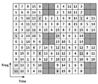
도 9는 PSS/SSS 및 DM-RS의 충돌을 도시하고 있다.Figure 9 shows the collision of PSS / SSS and DM-RS.
도 9에 도시한 바와 같이 동일한 위치/위치 중복에 따라 PSS/SSS와 DM-RS의 간섭/충돌 문제가 발생한다. 즉, 도 9의 910에 도시된 DM-RS와 920의 0/5번 서브프레임에서의 PSS/SSS는 동일한 시간 축 상의 심볼들에 할당된다. 한편, PSS/SSS 또는 DM-RS의 위치를 변경하므로 이러한 문제를 회피할 수 있는 방안들이 제시되고 있다. 물론, 이와 다른 실시예로 DM-RS의 위치 변경 대신 신호를 구분할 수 있도록 전송하는 방안도 고려할 수 있다. As shown in FIG. 9, an interference / collision problem between the PSS / SSS and the DM-RS occurs due to duplication of the same location / location. That is, the DM-RS shown in 910 of FIG. 9 and the PSS / SSS in the 0/5 sub-frame of 920 are allocated to symbols on the same time axis. Meanwhile, since the location of the PSS / SSS or the DM-RS is changed, a method for avoiding such a problem is suggested. Of course, in another embodiment, it is also possible to consider transmitting signals so that signals can be distinguished instead of changing the position of the DM-RS.
따라서, 상기 방안과 더불어 NCT에 PSS/SSS 또는 DM-RS의 위치를 변경하지 않고 PSS/SSS 및 DM-RS를 코드 분할 다중화(code divisional multiplexing)함으로 PSS/SSS와 DM-RS의 충돌을 회피할 수 있는 방안도 고려할 수 있다.Therefore, it is possible to avoid collision between the PSS / SSS and the DM-RS by performing code divisional multiplexing on the PSS / SSS and the DM-RS without changing the position of the PSS / SSS or DM-RS to the NCT It is also possible to consider measures.
아래에 상세히 설명하는 바와 같이 MU-MIMO을 지원하기 위해 DM-RS를 복소 복조심볼들에 매핑할 때 직교 시퀀스를 사용하여 다중화하였다.To support MU-MIMO as described in detail below, DM-RS is multiplexed using orthogonal sequences when mapping to complex demodulation symbols.
안테나 포트(안테나 포트 5에 대해서도 실질적으로 동일하게 적용함) ![]()
![]()
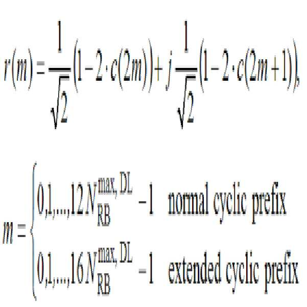
수학식 1에서 ![]()
![]()
![]()
![]()
수학식 2에서 ns는 슬롯 넘버로서 0 내지 19의 값을 가질 수 있다. nSCID는 스크램블링 아이디(scrambling identity)로서 0 또는 1의 값을 가질 수 있다. 

![]()
![]()
안테나 포트(안테나 포트 5에 대해서도 실질적으로 동일하게 적용함)에 대해, 주파수 도메인 인덱스 ![]()

![]()
PDSCH에 관련된 DM-RS의 시퀀스(r(m))가 매핑되는 자원 요소(resource element, RE)의 심볼 넘버(l) 및 서브캐리어 넘버(k)는 다음의 수학식 4과 같이 결정될 수 있다.The symbol number l and the subcarrier number k of the resource element RE to which the sequence r (m) of the DM-RS related to the PDSCH is mapped can be determined as shown in Equation (4).
[수학식 4]&Quot; (4) "
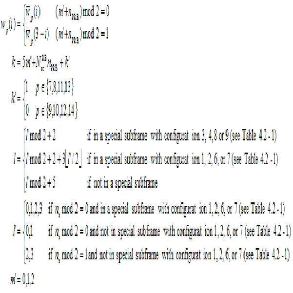
수학식 4에서 


한편, DM-RS의 일부 ![]()
![]()
![]()
![]()
PDSCH에 관련된 DM-RS의 시퀀스(r(m))가 매핑되는 자원 요소(resource element, RE)의 심볼 넘버(l) 및 서브캐리어 넘버(k)는 다음의 수학식 6과 같이 결정될 수 있다.The symbol number l and the subcarrier number k of the resource element RE to which the sequence r (m) of the DM-RS related to the PDSCH is mapped can be determined according to Equation (6).

이때 직교 시퀀스 
본 발명은 NCT에 PSS/SSS와 중첩되는 DM-RS의 위치를 변경하는 방식에 대해 살펴본다. 또한, 상기 실시예와 결합하여 DM-RS의 위치를 모두 변경할 수 없는 경우, 일부 중첩되는 신호에 대해서는 PSS/SSS 및 DM-RS를 코드 분할 다중화(code divisional multiplexing)함으로 PSS/SSS와 DM-RS의 충돌을 회피할 수 있는 방안을 제시한다. 예를 들어 PSS/SSS 및 DM-RS의 위치 중복/충돌시 DM-RS을 복소 복조심볼들에 매핑할 때 직교 시퀀스(orthogonal sequence)를 추가로 사용할 수 있다. 우선 코드 분할 다중화에 대해 살펴보면 다음과 같다. The present invention explains a method for changing the position of the DM-RS overlapping with the PSS / SSS in the NCT. If it is impossible to change the position of the DM-RS in combination with the above embodiment, the PSS / SSS and the DM-RS are subjected to code divisional multiplexing for some overlapping signals, This paper proposes a method to avoid collision of For example, an orthogonal sequence may be further used when mapping the DM-RS to the complex demodulation symbols in the position duplication / collision of the PSS / SSS and the DM-RS. First, code division multiplexing will be described as follows.
도 10은 PSS/SSS 및 DM-RS를 코드 분할 다중화(code divisional multiplexing)를 도시하고 있다. Figure 10 shows code divisional multiplexing of PSS / SSS and DM-RS.
도 9와 비교할 때, 코드 분할 다중화를 적용하므로 동일한 심볼에 위치하는 DM-RS와 PSS/SSS 간의 간섭을 회피할 수 있다. Compared with FIG. 9, since code division multiplexing is applied, interference between the DM-RS and the PSS / SSS located in the same symbol can be avoided.
구체적으로 DM-RS의 ![]()
![]()

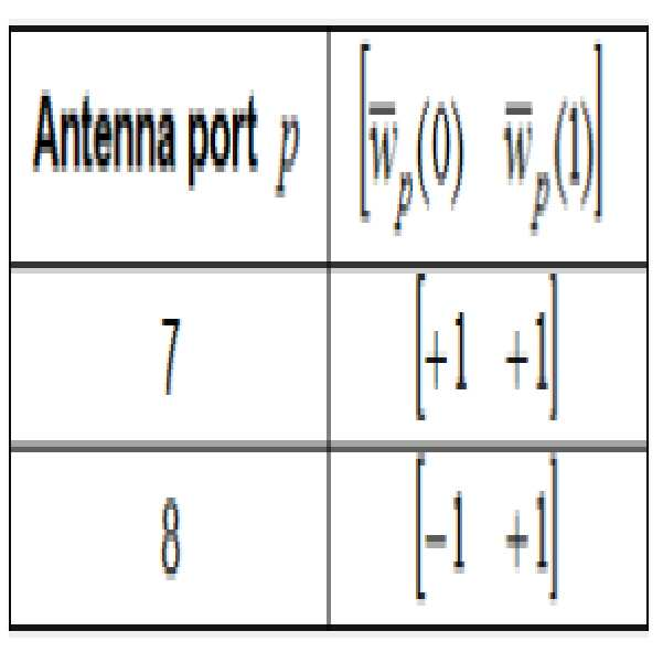
수학식 7에서 W(l)은 w(x,y)로 x는 해당 서브프레임에서 해당 슬롯의 심볼의 위치를, y는 서브캐리어의 위치를 의미한다.In Equation (7), W (l) denotes w (x, y), x denotes the position of the symbol of the corresponding slot in the corresponding subframe, and y denotes the position of the subcarrier.
따라서, w(x,y)가 w(5,0), w(6,0), w(5,1), w(6,1)인 경우나 w(x,y)가 w(5,5), w(6,5), w(5,6), w(6,6)인 경우나 w(x,y)가 w(5,10), w(6,10), w(5,11), w(6,11)인 경우에 ![]()
![]()
전송단은 DM-RS 및 PSS/SSS의 코드분할다중화에 사용된 직교코드를 단말에게 묵시적으로 또는 명시적으로(RRC signaling 또는 시스템 정보 등) 전송할 수 있으나, 이 직교코드를 전송하지 않고 단말이 후보 직교코드들을 순차적으로 블라인드 디코딩할 수도 있다. 다시 말해 도 10에 도시한 바와 같이 8개의 직교코드를 이용하여 DM-RS 및 PSS/SSS의 코드분할다중화한 경우 8개의 직교코드를 순차적으로 사용하여 블라인드 디코딩할 수 있다. 도 10의 코드 분할 다중화는 일부 DM-RS에 대해서만 적용할 수 있고, 위치 이동된 DM-RS에 대해서도 적용할 수 있다.
The transmission end may transmit the orthogonal code used for the code division multiplexing of the DM-RS and the PSS / SSS to the mobile station implicitly or explicitly (RRC signaling or system information), but without transmitting the orthogonal code, Orthogonal codes may be sequentially blind decoded. In other words, as shown in FIG. 10, when DM-RS and PSS / SSS are code division multiplexed using 8 orthogonal codes, 8 orthogonal codes can be sequentially used for blind decoding. The code division multiplexing of FIG. 10 can be applied to only a part of the DM-RSs, and can also be applied to the position-shifted DM-RSs.
이하, NCT에 PSS/SSS가 존재하는 경우 DM-RS와의 충돌을 회피하기 위해 DM-RS(복조참조신호)가 매핑되는 위치를 변경하는 과정을 살펴보고자 한다.Hereinafter, a process of changing a location where a DM-RS (demodulation reference signal) is mapped to avoid a collision with a DM-RS when a PSS / SSS exists in the NCT will be described.
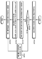
도 11은 본 발명의 일 실시예에 의한 기지국에서 복조참조신호를 전송하는 과정을 보여주는 도면이다.11 is a diagram illustrating a process of transmitting a demodulation reference signal in a base station according to an embodiment of the present invention.
기지국은 복조참조신호(DM-RS)를 전송할 캐리어의 타입을 확인한다(S1110). NCT인 경우(S1120), 기지국은 하향링크 서브프레임에 PSS 및 SSS가 배치되는 심볼을 파악한다(S1130). 이는 상기 캐리어의 하향링크 서브프레임에 배치되는 PSS 및 SSS와 시간 축으로 상이한 시간의 심볼에 복조참조신호를 매핑하기 위해서이다. 기지국은 상기 파악된 심볼의 위치와 시간축으로 상이한 시간의 심볼에 복조참조신호를 매핑한다(S1140). 그리고 기지국은 상기 매핑된 복조참조신호를 포함하는 하향링크를 전송한다(S1150). 반면, NCT가 아닌 경우 레가시 방식으로 복조참조신호를 매핑한다(S1160). The base station confirms the type of the carrier to which the demodulation reference signal DM-RS is to be transmitted (S1110). If it is the NCT (S1120), the base station grasps the symbol in which the PSS and the SSS are arranged in the downlink subframe (S1130). This is for mapping the demodulation reference signal to symbols of different time on the time axis from the PSS and SSS located in the downlink subframe of the carrier. The base station maps the demodulation reference signal to a symbol of a different time on the time axis and the position of the detected symbol (S1140). The base station transmits the downlink including the mapped demodulation reference signal (S1150). On the other hand, if it is not NCT, the demodulation reference signal is mapped in a legacy manner (S1160).
S1130 및 S1140에서 상기 PSS/SSS와 시간축으로 상이한 시간의 심볼은 구현 방식에 따라 다양하게 선택될 수 있다. 예를 들어, 상기 하향링크 서브프레임은 두 개의 슬롯으로 구성되며, 상기 복조참조신호는 상기 두 개의 슬롯 각각에서 시간 축으로 세 번째와 네 번째 심볼들에 위치하거나 또는 상기 첫 번째 슬롯에서 시간 축으로 세 번째와 네 번째 심볼들에 위치하며 상기 두 번째 슬롯에서 시간 축으로 여섯 번째와 일곱 번째 심볼들에 위치하도록 선택할 수 있다. 이 경우, 도 14에서 보다 상세히 살펴본다. 한편, 복조참조신호인 DM-RS의 위치 이동으로 인해 CSI 기준신호(CSI-RS)와 중첩될 수 있다. 이러한 상황은 도 15에서 제시되어 있다. 이 경우 기지국은 상기 CSI-RS를 재스케쥴링할 수 있다. 재스케쥴링한 CSI-RS는 다른 위치에서 전송될 수 있다. In S1130 and S1140, symbols of different time on the time axis from the PSS / SSS can be variously selected according to the implementation method. For example, the downlink subframe is composed of two slots, and the demodulation reference signal is located in the third and fourth symbols on the time axis in each of the two slots, or on the time axis in the first slot Third and fourth symbols, and may be located in the sixth and seventh symbols on the time axis in the second slot. This case will be described in more detail in Fig. On the other hand, it can be overlapped with the CSI reference signal (CSI-RS) due to the movement of the demodulation reference signal DM-RS. This situation is shown in Fig. In this case, the base station can reschedule the CSI-RS. The rescheduled CSI-RS may be transmitted at another location.
S1130 및 S1140에서 상기 PSS/SSS와 시간 축으로 상이한 시간의 심볼의 선택은 FDD인 경우 다음과 같이 구현될 수 있다. 두 개의 슬롯으로 구성되는 서브프레임에서 상기 서브프레임이 노멀 CP(normal Cyclic Prefix)인 경우 상기 복조참조신호는 상기 두 개의 슬롯 각각에서 시간 축으로 첫 번째와 두 번째 심볼들에 위치하며, 상기 서브프레임이 확장 CP(extended Cyclic Prefix)인 경우 상기 복조참조신호는 상기 두 개의 슬롯 각각에서 시간 축으로 두 번째와 세 번째 심볼들에 위치하도록 기지국이 제어할 수 있다. 이는 도 16에서 상세히 살펴본다. In S1130 and S1140, the selection of a symbol at a different time in the time axis from the PSS / SSS may be implemented as FDD. When the subframe is a normal CP (Normal Cyclic Prefix) in a subframe composed of two slots, the demodulation reference signal is located in the first and second symbols on the time axis in each of the two slots, In the case of the extended CP (Extended Cyclic Prefix), the BS can control the demodulation reference signal to be located in the second and third symbols on the time axis in each of the two slots. This will be described in detail with reference to FIG.
또한 TDD인 경우, 역시 두 개의 슬롯으로 구성되는 서브프레임 중 노멀 서브프레임(normal subframe)인 경우, 상기 복조참조신호는 상기 서브프레임의 두 번째 슬롯의 시간 축으로 마지막 심볼이 아닌 위치에 매핑되며, 스페셜 서브프레임(special subframe)인 경우, 상기 복조참조신호는 상기 서브프레임의 첫 번째 슬롯의 시간 축으로 세 번째 심볼이 아닌 위치에 매핑되도록 기지국이 제어할 수 있다. 도 17은 노멀 CP인 경우이며 도 18은 확장 CP인 경우를 보여준다.
Also, in case of TDD, in the case of a normal subframe among subframes of two slots, the demodulation reference signal is mapped to a position other than the last symbol on the time axis of the second slot of the subframe, In the case of a special subframe, the base station can control the demodulation reference signal to map to a position other than the third symbol on the time axis of the first slot of the subframe. FIG. 17 shows a case of a normal CP, and FIG. 18 shows a case of an extended CP.
도 12는 본 발명의 일 실시예에 의한 단말에서 복조참조신호를 수신하는 과정을 보여주는 도면이다. 12 is a diagram illustrating a process of receiving a demodulation reference signal in a UE according to an embodiment of the present invention.
단말은 복조참조신호(DM-RS)를 포함하는 하향링크를 수신한다(S1210). 그리고 복조참조신호가 전송된 캐리어의 타입을 확인한다(S1220). 확인 결과 NCT인 경우(S1230), 하향링크 서브프레임에 PSS 및 SSS가 배치되지 않은 심볼에서 복조참조신호를 확인한다(S1240). 다시 설명하면, 단말은 상기 캐리어의 하향링크 서브프레임에 배치되는 PSS 및 SSS와 시간 축으로 상이한 시간의 심볼에 매핑된 복조참조신호를 확인하게 된다. The UE receives the downlink including the demodulation reference signal DM-RS (S1210). Then, the type of the carrier to which the demodulation reference signal is transmitted is confirmed (S1220). If it is determined as NCT (S1230), the demodulation reference signal is checked in the symbol in which PSS and SSS are not arranged in the downlink subframe (S1240). To be more specific, the UE checks a demodulation reference signal mapped to symbols of different time on the time axis from the PSS and the SSS arranged in the downlink sub-frame of the carrier.
반면 NCT 타입이 아닌 경우 레가시 방식으로 복조참조신호를 확인한다(S1250).
On the other hand, if it is not the NCT type, the demodulation reference signal is checked in a legacy manner (S1250).
S1240에서 상기 PSS/SSS와 시간축으로 상이한 시간의 심볼의 위치는 구현 방식에 따라 다양하다. 예를 들어, 상기 하향링크 서브프레임은 두 개의 슬롯으로 구성되며, 상기 복조참조신호는 상기 두 개의 슬롯 각각에서 시간 축으로 세 번째와 네 번째 심볼들에 위치하거나 또는 상기 첫 번째 슬롯에서 시간 축으로 세 번째와 네 번째 심볼들에 위치하며 상기 두 번째 슬롯에서 시간 축으로 여섯 번째와 일곱 번째 심볼들에 위치할 수 있다. 이 경우, 도 14에서 보다 상세히 살펴본다. 한편, 복조참조신호인 DM-RS의 위치 이동으로 인해 CSI 기준신호(CSI-RS)와 중첩될 수 있다. 이러한 상황은 도 15에서 제시되어 있다. 이 경우 기지국은 상기 CSI-RS를 재스케쥴링하게 되며, 단말은 재스케쥴링된 CSI-RS를 확인하게 된다. In S1240, the positions of the symbols at different times on the time axis from the PSS / SSS vary depending on the implementation method. For example, the downlink subframe is composed of two slots, and the demodulation reference signal is located in the third and fourth symbols on the time axis in each of the two slots, or on the time axis in the first slot Third and fourth symbols and may be located in the sixth and seventh symbols on the time axis in the second slot. This case will be described in more detail in Fig. On the other hand, it can be overlapped with the CSI reference signal (CSI-RS) due to the movement of the demodulation reference signal DM-RS. This situation is shown in Fig. In this case, the BS reschedules the CSI-RS, and the MS confirms the rescheduled CSI-RS.
S1240에서 상기 PSS/SSS와 시간축으로 상이한 시간의 심볼의 위치는 FDD인 경우 다음과 같이 적용될 수 있다. 두 개의 슬롯으로 구성되는 서브프레임에서 상기 서브프레임이 노멀 CP(normal Cyclic Prefix)인 경우 상기 복조참조신호는 상기 두 개의 슬롯 각각에서 시간 축으로 첫 번째와 두 번째 심볼들에 위치하며, 상기 서브프레임이 확장 CP(extended Cyclic Prefix)인 경우 상기 복조참조신호는 상기 두 개의 슬롯 각각에서 시간 축으로 두 번째와 세 번째 심볼들에 위치하며 단말은 상기 위치에서 DM-RS를 확인할 수 있다. 이는 도 16에서 상세히 살펴본다. In S1240, when the position of a symbol at a different time on the time axis from the PSS / SSS is FDD, it can be applied as follows. When the subframe is a normal CP (Normal Cyclic Prefix) in a subframe composed of two slots, the demodulation reference signal is located in the first and second symbols on the time axis in each of the two slots, In the case of the extended CP (Extended Cyclic Prefix), the demodulation reference signal is located in the second and third symbols on the time axis in each of the two slots, and the UE can confirm the DM-RS at the position. This will be described in detail with reference to FIG.
또한 TDD인 경우, 역시 두 개의 슬롯으로 구성되는 서브프레임 중 노멀 서브프레임(normal subframe)인 경우, 상기 복조참조신호는 상기 서브프레임의 두 번째 슬롯의 시간 축으로 마지막 심볼이 아닌 위치에 매핑되며, 스페셜 서브프레임(special subframe)인 경우, 상기 복조참조신호는 상기 서브프레임의 첫 번째 슬롯의 시간 축으로 세 번째 심볼이 아닌 위치에 매핑되고, 단말은 상기 위치에서 DM-RS를 확인할 있다. 도 17은 노멀 CP인 경우이며 도 18은 확장 CP인 경우를 보여준다.
Also, in case of TDD, in the case of a normal subframe among subframes of two slots, the demodulation reference signal is mapped to a position other than the last symbol on the time axis of the second slot of the subframe, In the case of a special subframe, the demodulation reference signal is mapped to a position other than the third symbol on the time axis of the first slot of the subframe, and the UE confirms the DM-RS at the position. FIG. 17 shows a case of a normal CP, and FIG. 18 shows a case of an extended CP.
도 13은 5ms TRS 전송주기를 갖는 두 개의 이웃하는 NCT 셀들로 2ms 온 듀레이션(on duration)과 40ms의 DRX 주기를 가진 주파수내(intra-frequency) RRM 측정을 도시한 도면이다.Figure 13 shows intra-frequency RRM measurements with 2 ms on duration and 40 ms DRX periods in two neighboring NCT cells with a 5 ms TRS transmission period.
도 13에 도시한 바와 같이, 5ms TRS 전송주기를 갖는 두 개의 이웃하는 NCT 셀들로 2ms on duration과 40ms의 DRX 주기를 가진 intra-frequency RRM 측정을 가정한다. 도 13의 왼쪽 서클에 도시한 바와 같이 DRX 주기의 활성화 시간동안 전송되는 TRS가 없으므로 단말은 DRX 주기에 NCT 캐리어의 RSRP 측정을 할 수 없다. 따라서 이러한 경우에 DRX의 활성화 시간(on duration)을 적어도 하나의 TRS가 활성화 시간동안 전송될 수 있도록 5ms보다 작지 않게 설정할 수 있다.As shown in Fig. 13, assume an intra-frequency RRM measurement with 2 ms on duration and 40 ms DRX period with two neighboring NCT cells having a 5 ms TRS transmission period. As shown in the left circle of FIG. 13, since there is no TRS transmitted during the activation time of the DRX cycle, the UE can not perform the RSRP measurement of the NCT carrier in the DRX cycle. Therefore, in this case, DRX activation time (on duration) can be set not less than 5 ms so that at least one TRS can be transmitted during the activation time.
한편 CSI-RS 기반 RRM 측정시 하나의 NCT 셀을 위한 다중 CSI-RS 자원(multiple CRI-RS resource)에 기초로 RRM 측정이 측정 정확도를 증가시키기 위해 고려될 수 있다.On the other hand, RRM measurements based on multiple CSI-RS resources for one NCT cell in CSI-RS-based RRM measurements can be considered to increase measurement accuracy.
한편 TRS가 전송되는 경우 TRS 기반 RRM 측정이 수행되고 TRS가 전송되지 않는 경우 CSI-RS 기반 RRM 측정이 수행될 수 있다. 예를 들어 동기화 NCT의 경우 동기 정보가 레거시 캐리어로부터 전달된다. 따라서 동기화 캐리어 상에 PSS/SSS/TRS의 전송이 수행되지 않을 수 있다. 이 경우에 CSI-RS 기반 RRM 측정이 사용될 수 있다.
Meanwhile, when the TRS is transmitted, the TRS-based RRM measurement is performed, and when the TRS is not transmitted, the CSI-RS based RRM measurement can be performed. For example, in the case of a synchronous NCT, synchronization information is delivered from a legacy carrier. Therefore, the transmission of PSS / SSS / TRS may not be performed on the synchronization carrier. In this case, a CSI-RS based RRM measurement may be used.
도 14는 본 발명의 일 실시예에 따른 노멀 CP에 대한 DM-RS 패턴을 예시적으로 도시한 도면이다.14 is a diagram illustrating an exemplary DM-RS pattern for a normal CP according to an embodiment of the present invention.
도 14의 1410 및 1420에는 축소된 CRS(Reduced CRS)와 본 발명의 일 실시예에 따라 시간 축 상으로 이동하여 위치된 DM-RS를 보여주고 있다. 이동하여 위치된 DM-RS는 PSS/SSS와 중첩되지 않도록 이동되며, 이동하게 되는 심볼의 위치는 발명의 실시예에 따라 다양하게 적용될 수 있다. 14, 1410 and 1420 show a reduced CRS (Reduced CRS) and a DM-RS moved on the time axis according to an embodiment of the present invention. The moved DM-RS is moved so as not to overlap with the PSS / SSS, and the position of the moved symbol can be variously applied according to the embodiment of the present invention.
도 14의 1410을 참조하면, 다른 실시예에 따른 DM-RS 패턴은 각 슬롯의 세번째와 네번째 심볼들에 주파수축상으로 자원블럭의 양쪽 끝과 중앙의 4개의 자원요소에 위치할 수 있다. 구체적으로 수학식 7에서 각 슬롯에서 w(x,y)가 w(3,0), w(4,0), w(3,1), w(4,1) 또는 w(3,5), w(4,5), w(3,6), w(4,6) 또는 w(3,10), w(4,10), w(3,11), w(4,11)일 수 있다.Referring to 1410 of FIG. 14, the DM-RS pattern according to another embodiment may be located on four resource elements at both ends of a resource block on the frequency axis and in the center of the third and fourth symbols of each slot. Specifically, in
1420을 참조하면 다른 실시예에 따른 DM-RS 패턴은 첫번째 슬롯의 세번째와 네번째 심볼들에 주파수측상으로 자원블럭의 양쪽 끝과 중앙의 4개의 자원요소에 위치하고, 두번째 슬롯의 여섯번째와 일곱번째 심볼들의 주파수측상으로 자원블럭의 양쪽 끝과 중앙의 4개의 자원요소에 위치하도록 설계할 수도 있다. 구체적으로 수학식 7에서 첫번째 슬롯(ns=0)에서 w(x,y)가 w(3,0), w(4,0), w(3,1), w(4,1) 또는 w(3,5), w(4,5), w(3,6), w(4,6) 또는 w(3,10), w(4,10), w(3,11), w(4,11)이고, 두번째 슬롯(ns=1)에서, w(x,y)가 w(5,0), w(6,0), w(5,1), w(6,1) 또는 w(5,5), w(6,5), w(5,6), w(6,6) 또는 w(5,10), w(6,10), w(5,11), w(6,11)일 수 있다.1420, the DM-RS pattern according to another embodiment is located at the four resource elements at both ends and the center of the resource block on the frequency side in the third and fourth symbols of the first slot, and the sixth and seventh symbols On the frequency side of the resource block and at the four resource elements at the center and both ends of the resource block. Specifically, in
도 14에서의 DM-RS 패턴은 첫번째 슬롯의 경우 세번째와 네번째, 두번째 슬롯의 경우는 세번째와 네번째이거나 또는 여섯번째와 일곱번째 심볼들이 PSS/SSS와의 충돌을 회피하도록 이동하여 매핑한 것이다. The DM-RS pattern in FIG. 14 is mapped so as to avoid collision with the PSS / SSS in the third and fourth slots in the first slot and the third and fourth or sixth and seventh symbols in the second slot.
도 15는 CSI-RS가 설정된 CSI-RS 패턴을 도시한 도면이다.15 is a diagram illustrating a CSI-RS pattern in which a CSI-RS is set.
도 15는 두번째 슬롯의 세번째와 네번째 심볼들의 자원요소들에는 CSI-RS가 설정된 CSI-RS 패턴을 도시하고 있다.FIG. 15 shows a CSI-RS pattern in which CSI-RS is set in the resource elements of the third and fourth symbols of the second slot.
도 15에 도시한 바와 같이 두번째 슬롯의 세번째와 네번째 심볼들의 자원요소들에는 CSI-RS가 설정될 수 있어, 도 14의 1410에 도시한 DM-RS 패턴을 사용할 경우 두번째 슬롯의 세번째와 네번째 심볼들의 자원요소들 상 중첩될 수 있다. 따라서 기지국(전송당 또는 서빙 셀)은 도 14의 1410에 도시한 DM-RS 패턴을 사용할 경우 도 14에 도시한 DM-RS 패턴과 중첩되지 않도록 CSI-RS를 구성하도록 스케줄링할 수 있다.As shown in FIG. 15, the CSI-RS can be set in the resource elements of the third and fourth symbols of the second slot. When the DM-RS pattern shown in 1410 of FIG. 14 is used, the third and fourth symbols The resource elements can be overlapped. Therefore, when using the DM-RS pattern shown in 1410 of FIG. 14, the base station (per-transmission or serving cell) can be scheduled to configure the CSI-RS so as not to overlap with the DM-RS pattern shown in FIG.
도 14의 1410에 도시한 다른 실시예에 따른 DM-RS 패턴은 제어영역이 존재하지 않은 NCT에서 PSS/SSS와 중첩/충돌문제도 해결하면서 각 슬롯의 중앙부분에 균일하게 DM-RS 자원들이 위치하므로 자원블럭 전체의 복조효율을 향상시킬 수 있다. 다만 도 14의 1410에 도시한 다른 실시예에 따른 DM-RS 패턴은 두번째 슬롯에서 CSI-RS 자원들과 중첩될 수 있으나, 기지국(전송단 또는 서빙 셀)은 도 14에 도시한 DM-RS 패턴과 중첩되지 않도록 CSI-RS를 구성하도록 스케줄링할 수 있다.The DM-RS pattern according to another embodiment shown in 1410 of FIG. 14 solves the overlap / collision problem with the PSS / SSS in the NCT in which the control region does not exist, and uniformly distributes DM-RS resources The demodulation efficiency of the entire resource block can be improved. 14, a DM-RS pattern according to another embodiment may be overlapped with CSI-RS resources in a second slot, but a base station (a transmitting end or a serving cell) And to configure the CSI-RS so as not to overlap with the CSI-RS.
도 14의 1420에 도시한 다른 실시예에 따른 DM-RS 패턴은 제어영역이 존재하지 않은 NCT에서 PSS/SSS와 중첩/충돌문제도 해결하면서 CSI-RS 자원과 중첩/충돌 문제도 발생하지 않아 기지국(전송단 또는 서빙 셀)의 자원 할당시 자유롭게 자원들을 스케줄링할 수 있다.The DM-RS pattern according to another embodiment shown in 1420 of FIG. 14 also solves the overlay / collision problem with the PSS / SSS in the NCT in which the control region does not exist, and the overlapping / collision problem with the CSI- (A transmitting end or a serving cell).
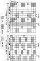
도 16은 본 발명의 일 실시예에 의한 FDD의 경우에 노멀 CP와 확장 CP에 대한 DM-RS 패턴을 예시적으로 도시한 도면이다.16 is a diagram illustrating a DM-RS pattern for a normal CP and an extended CP in the case of an FDD according to an embodiment of the present invention.
도 16을 참조하면, 또 다른 실시예에 따른 DM-RS 패턴은 도 16의 1610에 도시한 바와 같이 노멀 CP에 대해 첫번째 슬롯(짝수번째 슬롯, even-numbered slot)와 두번째 슬롯(홀수번째 슬롯, odd-numbered slot) 각각의 첫번째와 두번째 심볼들에 주파수측상으로 자원블럭의 양쪽 끝과 중앙의 4개의 자원요소에 위치할 수 있다. 구체적으로 수학식 7에서 첫번째 슬롯(ns=0)와 두번째 슬롯 두번째 슬롯(ns=1)에서 w(x,y)가 w(0,0), w(1,0), w(0,1), w(1,1) 또는 w(0,5), w(1,5), w(0,6), w(1,6) 또는 w(0,10), w(1,10), w(0,11), w(1,11)일 수 있다. 1620에 도시한 바와 같이 확장 CP에 대해 첫번째 슬롯의 두번째와 세번째 심볼들에 주파수측상으로 두번째, 다섯번째, 여덟번째, 열한번째의 자원요소들이 DM-RS 자원들이 위치하고, 두번째 슬롯의 두번째와 세번째 심볼들에 주파수측상으로 첫번째, 네번째, 일곱번째, 열번째의 자원요소들이 DM-RS 자원들이 위치할 수 있다.Referring to FIG. 16, the DM-RS pattern according to another embodiment may include a first slot (even-numbered slot) and a second slot (odd-numbered slot, odd-numbered slot) The first and second symbols of each can be located on the frequency side on the four resource elements at both ends of the resource block and in the center. Specifically, w (x, y) in the first slot (n s = 0) and the second slot (n s = 1) W (1, 1), w (1,1) or w (0,5) 10), w (0, 11), w (1,11). As shown in 1620, for the extended CP, the DM-RS resources are located in the second and third symbols of the first slot on the frequency side and the resource elements of the second, fifth, eighth, eleventh, and the second and third symbols of the second slot, The first, fourth, seventh, and tenth resource elements on the frequency side may contain DM-RS resources.
도 16에서 1610에서는 SSS와 PSS는 첫번째 슬롯의 6, 7번째 심볼들에 위치하므로 DM-RS와 충돌하지 않는다. 마찬가지로 1620에서는 SSS와 PSS는 첫번째 슬롯의 5, 6번째 심볼들에 위치하므로 DM-RS와 충돌하지 않는다.
16, the SSS and the PSS do not collide with the DM-RS because they are located in the 6th and 7th symbols of the first slot. Likewise, in 1620, the SSS and the PSS are located in the 5th and 6th symbols of the first slot, so that they do not collide with the DM-RS.
도 17 및 도 18은 본 발명의 일 실시예에 의한 TDD의 경우에 노멀 CP와 확장 CP에 대한 DM-RS 패턴을 예시적으로 도시한 도면이다.도 17 및 18에서는 TDD 인 경우, 노멀 서브프레임에서는 상기 서브프레임의 두 번째 슬롯의 시간 축으로 마지막 심볼에 SSS/PSS가 위치하므로 이 위치가 아닌 심볼에 DM-RS를 매핑할 수 있다. 마찬가지로 스페셜 서브프레임에서는 상기 서브프레임의 첫 번째 슬롯의 시간 축으로 세 번째 심볼에 SSS/PSS가 위치하므로 이 위치가 아닌 심볼에 DM-RS를 매핑할 수 있다. 17 and 18 illustrate a DM-RS pattern for a normal CP and an extended CP in the case of TDD according to an embodiment of the present invention. Since the SSS / PSS is located in the last symbol on the time axis of the second slot of the subframe, the DM-RS can be mapped to a symbol other than the SSS / PSS. Likewise, in the special subframe, since the SSS / PSS is located in the third symbol on the time axis of the first slot of the subframe, the DM-RS can be mapped to a symbol other than the SSS / PSS.
도 17은 노멀 CP에 해당하며 도면을 참조하면, DM-RS 패턴은 TDD의 경우 노멀 서브프레임의 마지막 심볼과 스페셜 서브프레임(special subframe)의 세번째 심볼들에 SSS와 PSS 신호들이 위치하므로 이들과 충돌하지 않도록 DM-RS 패턴을 설계할 수 있다. 도 17에서 DM-RS는 노멀 서브프레임인 경우 첫번째 및 두번째 슬롯의 시간 축으로 다섯번째, 여섯번째 심볼들 중에 주파수측상으로 자원블럭의 양쪽 끝과 중앙의 4개의 자원요소에 위치할 수 있다. 또한 DM-RS는 스페셜 서브프레임의 경우, 첫번째 슬롯의 시간 축으로 첫번째, 두번째 심볼과 여섯번째, 일곱번째 심볼에 대해 주파수측상으로 자원블럭의 양쪽 끝과 중앙의 4개의 자원요소에 위치할 수 있다.
Referring to FIG. 17, the DM-RS pattern includes SSS and PSS signals in the last symbol of the normal subframe and the third symbol of the special subframe in case of TDD, DM-RS pattern can be designed so that In FIG. 17, the DM-RS can be located at four resource elements at both ends of the resource block and at the center on the frequency side among the fifth and sixth symbols on the time axis of the first and second slots in the case of a normal sub-frame. In the case of special subframes, the DM-RS can also be located on the frequency side for the first, second, sixth and seventh symbols on the time axis of the first slot and at the four resource elements at both ends and the center of the resource block .
도 18은 확장 CP에 해당하며 도면을 참조하면, DM-RS 패턴은 TDD의 경우 노멀 서브프레임과 스페셜 서브프레임(special subframe) 각각의 마지막 심볼과 세번째 심볼들에 SSS/PSS 신호들이 위치하므로 이들과 충돌하지 않도록 DM-RS 패턴을 설계할 수 있다. 도 18에서 DM-RS는 노멀 서브프레임인 경우 첫 번째 슬롯의 시간 축으로 두번째 및 세번째 심볼들에 대해 주파수측상으로 두번째, 다섯번째, 여덟번째, 열한번째의 자원요소들이 DM-RS 자원들이 위치하고, 두번째 슬롯의 시간 축으로 두번째와 세번째 심볼들에 주파수측상으로 첫번째, 네번째, 일곱번째, 열번째의 자원요소들이 DM-RS 자원들이 위치할 수 있다.Referring to FIG. 18, the DM-RS pattern includes SSS / PSS signals in the last and third symbols of a normal subframe and a special subframe in case of TDD, The DM-RS pattern can be designed to avoid collision. In FIG. 18, in the case of the normal sub-frame, the DM-RS has the DM-RS resources of the second, fifth, eighth and eleventh resource elements on the frequency side with respect to the second and third symbols on the time axis of the first slot, The first, fourth, seventh, and tenth resource elements on the frequency side to the second and third symbols on the time axis of the slot may contain DM-RS resources.
한편 DM-RS는 스페셜 서브프레임인 경우, 첫번째 슬롯의 시간 축으로 다섯번째 및 여섯번째 심볼들에 주파수측상으로 두번째, 다섯번째, 여덟번째, 열한번째의 자원요소들이 DM-RS 자원들이 위치한다.
On the other hand, when the DM-RS is a special subframe, DM-RS resources are allocated to the fifth and sixth symbols on the time axis of the first slot, and the second, fifth, eighth, and eleventh resource elements on the frequency side.
2. NCT를 위한 RRM 측정(RRM measurements for NCT)2. RRM measurements for NCT (RRM measurements for NCT)
NCT를 위한 RRM 측정의 기능은 이동성(핸드오버 또는 셀 (재)선택)을 위한 것이 아니라 단말에 의한 RRM 측정 리포트들에 기초하여 SCell로써 NCT의 추가 또는 제거를 결정하는데 전송단(기지국)의 성능을 위한 것이다. NCT를 위한 RRM 측정은 주파수 간(inter-frequency) 뿐만 아니라 주파수 내(intra-frequency) 측정을 위해 RRC 연결된(RRC connected) 단말들에만 적용할 수 있다. 다시말해 아이들(idle) 모드에 대한 RRM 측정은 필요하지 않다. RRM 측정은 동기화 NCT와 비동기화 NCT 모두에 적용할 수 있다. CA와 마찬가지로 RSRQ와 RSRQ 행렬들이 NCT RRM 측정을 위해 정의될 수 있다. SCell의 추가/제거를 위해 CA에 대해 정의한 RRM 측정 모델 및 절차들이 NCT에 대해 재사용될 수 있다. The function of the RRM measurement for the NCT is not for mobility (handover or cell (re-selection), but rather determines the addition or removal of the NCT with SCell based on the RRM measurement reports by the terminal, . The RRM measurement for the NCT is applicable not only to inter-frequency but also to RRC connected terminals for intra-frequency measurements. In other words, the RRM measurement for the idle mode is not necessary. RRM measurements can be applied to both synchronous NCT and asynchronous NCT. Like CA, RSRQ and RSRQ matrices can be defined for NCT RRM measurements. RRM measurement models and procedures defined for the CA for SCell addition / removal can be reused for the NCT.

NCT는 정의상 레거시 CRS를 전송하지 않는다. 따라서 NCT를 위한 RRM 측정을 위한 다른 RS가 사용될 필요가 있다. NCT 상에 RS 전송은 CSI-RS, DM-RS 및 PSS/SSS를 포함한다. 주파수 및 시간 동기를 목적으로 NCT는 5ms 주기로 하나의 서브프레임에 1RS 포트(PRB당 Rel-8 CRS 포트 0 RE들 및 Rel-8 시퀀스로 구성된)을 운반할 수 있다.NCT does not transmit legacy CRS by definition. Therefore, another RS for RRM measurement for NCT needs to be used. RS transmissions on the NCT include CSI-RS, DM-RS and PSS / SSS. For frequency and time synchronization purposes, the NCT can carry 1RS ports (consisting of Rel-8
NCT 상에 전송되는 신호들 중 단지 CSI-RS 및 TRS(또는 이들의 조합) 중 적어도 하나만이 RRM 측정을 위한 RS들로 고려될 수 있다. Of the signals transmitted on the NCT, only at least one of CSI-RS and TRS (or a combination thereof) can be considered as RSs for RRM measurement.
TRS가 동기화 및 비동기화 캐리어들 모두에 사용될 경우 TRS가 RRM 측정을 위한 RS로 사용될 수 있다. 이때 동일한 RRM 측정 방법이 동기화 및 비동기화 NCT에 적용될 수 있다. 주기적 TRS 전송으로 RRM 측정을 위한 TRS 서브프레임들 중 서브프레임들을 선택하기 위해 단말은 TRS가 언제 전송되는지 알아야 한다. 서빙 셀 RRM 측정을 위해, 단말은 셀 타입(예를 들어 Legacy Cell Type(LCT) 또는 NCT)와 TRS 서브프레임들(구성되었다면)의 서브프레임 오프셋과 같은 시스템 정보를 획득해야 한다. 주파수 내(Intra-frequency) RRM 측정을 위해, 이웃 셀의 TRS 서브프레임들의 정보가 항상 단말에 알려질 수 없다. 한편 단말은 측정 객체(measurement object)를 갖도록 구성된 경우 측정 요구(measurement request)는 타켓 셀의 셀 타입 또는 TRS의 정보를 포함할 수 있다. If the TRS is used for both synchronous and asynchronous carriers, the TRS can be used as an RS for RRM measurements. At this time, the same RRM measurement method can be applied to synchronous and asynchronous NCTs. In order to select subframes among the TRS subframes for RRM measurement with periodic TRS transmission, the UE must know when the TRS is transmitted. For serving cell RRM measurements, the terminal must obtain system information such as the cell type (e.g., Legacy Cell Type (LCT) or NCT) and the subframe offset of the TRS subframes (if configured). For intra-frequency RRM measurement, information of TRS sub-frames of neighboring cells can not always be known to the UE. Meanwhile, if the UE is configured to have a measurement object, the measurement request may include the cell type of the target cell or the information of the TRS.
앞서 도 13에 도시한 바와 같이, 5ms TRS 전송주기를 갖는 두 개의 이웃하는 NCT 셀들로 2ms 온 듀레이션(on duration)과 40ms의 DRX 주기를 가진 주파수 내(intra-frequency) RRM 측정을 가정한다. 도 13의 왼쪽 서클에 도시한 바와 같이 DRX 주기의 활성화 시간동안 전송되는 TRS가 없으므로 단말은 DRX 주기에 NCT 캐리어의 RSRP 측정을 할 수 없다. 따라서 이러한 경우에 DRX의 활성화 시간(on duration)을 적어도 하나의 TRS가 활성화 시간동안 전송될 수 있도록 5ms보다 작지 않게 설정할 수 있다.As shown in FIG. 13, assume an intra-frequency RRM measurement with 2 ms on duration and 40 ms DRX periods in two neighboring NCT cells with a 5 ms TRS transmission period. As shown in the left circle of FIG. 13, since there is no TRS transmitted during the activation time of the DRX cycle, the UE can not perform the RSRP measurement of the NCT carrier in the DRX cycle. Therefore, in this case, DRX activation time (on duration) can be set not less than 5 ms so that at least one TRS can be transmitted during the activation time.
한편 CSI-RS 기반 RRM 측정시 하나의 NCT 셀을 위한 다중 CSI-RS 자원(multiple CRI-RS resource)에 기초로 RRM 측정이 측정 정확도를 증가시키기 위해 고려될 수 있다.On the other hand, RRM measurements based on multiple CSI-RS resources for one NCT cell in CSI-RS-based RRM measurements can be considered to increase measurement accuracy.
한편 TRS가 전송되는 경우 TRS 기반 RRM 측정이 수행되고 TRS가 전송되지 않는 경우 CSI-RS 기반 RRM 측정이 수행될 수 있다. 예를 들어 동기화 NCT의 경우 동기 정보가 레거시 캐리어로부터 전달된다. 따라서 동기화 캐리어 상에 PSS/SSS/TRS의 전송이 수행되지 않을 수 있다. 이 경우에 CSI-RS 기반 RRM 측정이 사용될 수 있다.
Meanwhile, when the TRS is transmitted, the TRS-based RRM measurement is performed, and when the TRS is not transmitted, the CSI-RS based RRM measurement can be performed. For example, in the case of a synchronous NCT, synchronization information is delivered from a legacy carrier. Therefore, the transmission of PSS / SSS / TRS may not be performed on the synchronization carrier. In this case, a CSI-RS based RRM measurement may be used.
3. 동기화 NCT들(Synchronised new carriers)3. Synchronized new carriers (NCTs)
동기화 NCT들(Synchronised new carriers)은 단일 RF 프론트 엔드(front end)를 사용하는 밴드 내 연속된 CA(intra-band contiguous carrier aggregation)의 경우로 한정될 수 있다. CRS는 시간/주파수 트래킹(tracking)에 무관하게 RRM 측정을 목적으로 전송될 수 있다. 한편 PSS/SSS는 제거될 수 있다. Synchronized new carriers may be limited to the case of intra-band contiguous carrier aggregation (CA) in a band using a single RF front end. The CRS can be transmitted for RRM measurement purposes regardless of time / frequency tracking. On the other hand, PSS / SSS can be eliminated.
반면에, 동기화 NCT의 시간/주파수 동기 및 트래킹을 위한 RS들은 상위계층 시그널링에 의해 단말에 시그널링(전송/전달)될 수 있다. 이 경우 PSS/SSS/CRS/TRS들은 동기화 NCT에 대해 전송되지 않을 수 있다.On the other hand, RSs for time / frequency synchronization and tracking of the synchronous NCT can be signaled (transmitted / forwarded) to the terminal by higher layer signaling. In this case, the PSS / SSS / CRS / TRSs may not be transmitted for the synchronization NCT.
세그먼트가, 하향링크에 대해서만, 백워드 컴패터블 캐리어(backward compatible carrier(BCC))와 동일 밴드에 있을 수 있다. 이때 세그먼트 크기는 BCC 이하일 수 있다. BCC와 세그먼트는 시간/주파수상 동기화될 수 있다. PSS/SSS/PBCH/SIBs은 세그먼트에 전송되지 않는다. 단일 (E)PDCCH DCI는 BCC와 세그먼트를 지시한다. BCC와 세그먼트를 위한 하나의 HARQ가 사용될 수 있다. BCC와 세그먼트의 최대 자원할당 크기는 110PRB 쌍(20MHz)일 수 있다. 세그먼트는 단지 유니캐스트(unicast) PDSCH를 지원할 수 있다. CRS는 세그먼트 상에 전송되고 TM1-10이 지원될 수 있다. BCC와 세그먼트 사이 가드 밴드(guard band)가 있을 수 있다. 세그먼트는 BCC의 한쪽 에지(edge) 또는 양쪽 에지들에 존재할 수 있다. The segment may be in the same band as the backward compatible carrier (BCC) only for the downlink. At this time, the segment size may be equal to or less than BCC. The BCC and segment can be time / frequency synchronized. PSS / SSS / PBCH / SIBs are not sent to the segment. The single (E) PDCCH DCI indicates the BCC and the segment. One BCC and one HARQ for the segment may be used. The maximum resource allocation size of the BCC and the segment may be 110 PRB pairs (20 MHz). The segment may only support a unicast PDSCH. CRS can be sent on segments and TM1-10 can be supported. There can be a guard band between the BCC and the segment. The segment may be at one edge or both edges of the BCC.
이상 NCT의 구조 및 전송방법에 대해 설명하였으나 이하에서 설명하는 기지국 및 단말은 전술한 NCT의 구조 및 전송방법을 수행할 수 있다. Although the structure and transmission method of the NCT have been described above, the base station and the terminal described below can perform the structure and transmission method of the NCT described above.
도 19는 본 발명의 일 실시예에 의한 기지국의 구성을 보여주는 도면이다. 도 19는 앞서 도 11 및 도 14 내지 도 18에서 살펴본 실시예를 구현하는 장치이다. 19 is a diagram illustrating a configuration of a base station according to an embodiment of the present invention. Fig. 19 is an apparatus for implementing the embodiment shown in Fig. 11 and Fig. 14 to Fig.
도 19를 참조하면, 또 다른 실시예에 의한 기지국(1900)은 제어부(1910)과 송신부(1920), 수신부(1930)를 포함한다.19, a
제어부(1910)는 전술한 본 발명을 수행하기에 필요한 NCT의 구조 및 동작에 따른 전반적인 기지국의 동작을 제어한다. The
송신부(1920)와 수신부(1930)는 전술한 본 발명을 수행하기에 필요한 신호나 메시지, 데이터를 단말과 송수신하는데 사용된다. The
보다 상세히 살펴보면, 기지국은 NCT인 캐리어에서 복조참조신호를 전송하며, 이를 위해 제어부(1910)는 상기 캐리어의 하향링크 서브프레임에 배치되는 PSS 및 SSS와 시간 축으로 상이한 시간의 심볼에 복조참조신호를 매핑한다. 상기 송신부(1920)는 상기 매핑된 복조참조신호를 포함하는 하향링크를 전송하며, 상기 수신부(1930)는 상기 하향링크를 수신한 단말로부터 신호를 수신한다. 상기 PSS 및 SSS와 충돌하지 않도록 시간 축으로 상이한 시간의 심볼에 복조참조신호를 매핑하는 세부적인 실시예는 앞서 도 11 및 도 14 내지 도 18에서 살펴보았다.
In more detail, the base station transmits a demodulation reference signal in a carrier, which is an NCT. To this end, the
도 20은 본 발명의 일 실시예에 의한 사용자 단말의 구성을 보여주는 도면이다.20 is a diagram illustrating a configuration of a user terminal according to an embodiment of the present invention.
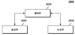
도 20을 참조하면, 또 다른 실시예에 의한 사용자 단말(2000)은 수신부(2030) 및 제어부(2010), 송신부(2020)을 포함한다. 도 20은 앞서 도 12 및 도 14 내지 도 18에서 살펴본 실시예를 구현하는 장치이다.Referring to FIG. 20, a
수신부(2030)는 기지국으로부터 하향링크 제어정보 및 데이터, 메시지를 해당 채널을 통해 수신한다.The
또한 제어부(2010)는 전술한 본 발명을 수행하기에 NCT의 구조 및 동작에 따른 전반적인 단말의 동작을 제어한다. In addition, the
송신부(2020)는 기지국에 하향링크 제어정보 및 데이터, 메시지를 해당 채널을 통해 전송한다.The
보다 상세히 살펴보면 단말(2000)의 수신부(2030)는 복조참조신호를 포함하는 하향링크를 수신하며, 제어부(2010)는 상기 캐리어의 하향링크 서브프레임에 배치되는 PSS 및 SSS와 시간 축으로 상이한 시간의 심볼에 매핑된 복조참조신호를 확인한다. 이후 송신부(2020)는 상기 기지국에게 신호를 송신한다. 상기 심볼에 매핑되는 복조참조신호의 실시예는 앞서 도 12 및 도 14 내지 도 18에서 살펴본 실시예를 참고한다. In more detail, the
지금까지 살펴본 시간축을 기준으로 충돌을 회피하는 DM-RS 신호의 매핑 위치를 변경하는 방식 이외에도 PSS/SSS가 할당된 주파수 대역이 아닌 주파수 대역에만 DM-RS가 할당되도록 할 수 있다. 예를 들어, 중심 주파수의 6개의 RB에 PSS/SSS가 할당된 경우, 이 위치에 매핑될 DM-RS는 이 위치에는 매핑시키지 않는 대신, 해당 시간축의 다른 주파수 대역, 예를 들어 상기 PSS/SSS가 매핑된 주파수 대역에 인접한 주파수 대역에 DM-RS가 할당되도록 구현할 수 있다. 즉, 6개의 RB에 PSS/SSS가 할당된 경우 인접한 주파수 대역의 RB에 DM-RS를 매핑할 수 있다.In addition to the method of changing the mapping position of the DM-RS signal for avoiding the collision on the basis of the time axis thus far examined, the DM-RS can be allocated only to the frequency band other than the frequency band to which the PSS / SSS is allocated. For example, when PSS / SSS is allocated to six RBs at the center frequency, the DM-RS to be mapped to this position is not mapped to this position, but instead is mapped to another frequency band of the corresponding time axis, The DM-RS may be allocated to a frequency band adjacent to the frequency band to which the DM-RS is mapped. That is, when PSS / SSS is allocated to six RBs, DM-RSs can be mapped to RBs of adjacent frequency bands.
또한, 앞서 살펴본 바와 같이 DM-RS와 PSS/SSS가 충돌되는 주파수에서 DM-RS를 펑쳐링(puncturing) 하는 방식도 고려할 수 있으며, 이와 반대로 PSS/SSS를 펑처링하는 방안도 고려할 수 있다. Also, as mentioned above, a method of puncturing the DM-RS at a frequency at which the DM-RS collides with the PSS / SSS may be considered, and a method of puncturing the PSS / SSS may be considered.
본 발명의 다양한 실시예에서는 PSS/SSS가 할당되는 심볼의 시간축 및 주파수 축을 고려하여 DM-RS의 주파수 영역을 유지하며 시간축을 이동시키거나, 또는 시간축을 유지하며 주파수 영역을 일부 이동시키거나 또는 주파수 영역과 시간축 영역을 유지하며 DM-RS 또는 PSS/SSS를 펑처링하여 두 신호의 간섭을 제거할 수 있다.
In various embodiments of the present invention, in consideration of the time axis and the frequency axis of the symbol to which the PSS / SSS is allocated, the DM-RS maintains the frequency domain of the DM-RS and moves the time axis, or maintains the time axis, The DM-RS or PSS / SSS can be punctured to maintain interference between the two signals while maintaining the domain and time-domain domain.
이상의 설명은 본 발명의 기술 사상을 예시적으로 설명한 것에 불과한 것으로서, 본 발명이 속하는 기술 분야에서 통상의 지식을 가진 자라면 본 발명의 본질적인 특성에서 벗어나지 않는 범위에서 다양한 수정 및 변형이 가능할 것이다. 따라서, 본 발명에 개시된 실시 예들은 본 발명의 기술 사상을 한정하기 위한 것이 아니라 설명하기 위한 것이고, 이러한 실시 예에 의하여 본 발명의 기술 사상의 범위가 한정되는 것은 아니다. 본 발명의 보호 범위는 아래의 청구범위에 의하여 해석되어야 하며, 그와 동등한 범위 내에 있는 모든 기술 사상은 본 발명의 권리범위에 포함되는 것으로 해석되어야 할 것이다.The foregoing description is merely illustrative of the technical idea of the present invention, and various changes and modifications may be made by those skilled in the art without departing from the essential characteristics of the present invention. Therefore, the embodiments disclosed in the present invention are intended to illustrate rather than limit the scope of the present invention, and the scope of the technical idea of the present invention is not limited by these embodiments. The scope of protection of the present invention should be construed according to the following claims, and all technical ideas falling within the scope of the same shall be construed as falling within the scope of the present invention.
Claims (11)
상기 캐리어의 하향링크 서브프레임(Downlink Subframe)에 배치되는 PSS(Primary Synchronization Signal) 및 SSS(Secondary Synchronization Signal)와 시간 축으로 상이한 시간의 심볼에 복조참조신호를 매핑하는 단계; 및
상기 매핑된 복조참조신호를 포함하는 하향링크를 전송하는 단계를 포함하는 방법.
A method for transmitting a demodulation reference signal from a carrier, the carrier being a New Carrier Type (NCT)
Mapping a demodulation reference signal to a symbol of a different time on a time axis with a Primary Synchronization Signal (PSS) and a Secondary Synchronization Signal (SSS) arranged in a downlink subframe of the carrier; And
And transmitting the downlink including the mapped demodulation reference signal.
상기 하향링크 서브프레임은 두 개의 슬롯으로 구성되며,
상기 복조참조신호는 상기 두 개의 슬롯 각각에서 시간 축으로 세 번째와 네 번째 심볼들에 위치하거나 또는 상기 첫 번째 슬롯에서 시간 축으로 세 번째와 네 번째 심볼들에 위치하며 상기 두 번째 슬롯에서 시간 축으로 여섯 번째와 일곱 번째 심볼들에 위치하는 것을 특징으로 하는 방법.
The method according to claim 1,
The downlink subframe is composed of two slots,
Wherein the demodulation reference signal is located in third and fourth symbols on a time axis in each of the two slots or in third and fourth symbols in a time axis in the first slot, ≪ / RTI > in the sixth and seventh symbols.
상기 하향링크 서브프레임의 CSI 기준신호(Channel State Information Reference Signal)가 상기 복조참조신호와 심볼이 중첩될 경우 상기 CSI-RS를 재스케쥴링하는 단계를 더 포함하는 방법.
The method according to claim 1,
Further comprising rescheduling the CSI-RS when the CSI reference signal of the downlink subframe overlaps the demodulation reference signal and the symbol.
상기 하향링크 서브프레임은 FDD(Frequency Division Duplex)방식으로 두 개의 슬롯으로 구성되며,
상기 서브프레임이 노멀 CP(normal Cyclic Prefix)인 경우 상기 복조참조신호는 상기 두 개의 슬롯 각각에서 시간 축으로 첫 번째와 두 번째 심볼들에 위치하며,
상기 서브프레임이 확장 CP(extended Cyclic Prefix)인 경우 상기 복조참조신호는 상기 두 개의 슬롯 각각에서 시간 축으로 두 번째와 세 번째 심볼들에 위치하는 것을 특징으로 하는 방법.
The method according to claim 1,
The downlink subframe is composed of two slots in an FDD (Frequency Division Duplex) scheme,
If the subframe is a normal CP (Normal Cyclic Prefix), the demodulation reference signal is located in the first and second symbols on the time axis in each of the two slots,
Wherein the demodulation reference signal is located in second and third symbols on a time axis in each of the two slots when the subframe is an extended CP (Extended CP).
상기 하향링크 서브프레임은 TDD(Time Division Duplex)방식으로 두 개의 슬롯으로 구성되며,
상기 하향링크 서브프레임이 노멀 서브프레임(normal subframe)인 경우, 상기 복조참조신호는 상기 서브프레임의 두 번째 슬롯의 시간 축으로 마지막 심볼이 아닌 위치에 매핑되며,
상기 하향링크 서브프레임이 스페셜 서브프레임(special subframe)인 경우, 상기 복조참조신호는 상기 서브프레임의 첫 번째 슬롯의 시간 축으로 세 번째 심볼이 아닌 위치에 매핑되는 것을 특징으로 하는 방법.
The method according to claim 1,
The downlink subframe is composed of two slots in a TDD (Time Division Duplex) scheme,
If the downlink subframe is a normal subframe, the demodulation reference signal is mapped to a position other than the last symbol on a time axis of a second slot of the subframe,
Wherein when the downlink subframe is a special subframe, the demodulation reference signal is mapped to a position other than a third symbol on a time axis of a first slot of the subframe.
복조참조신호를 포함하는 하향링크를 수신하는 단계; 및
상기 캐리어의 하향링크 서브프레임(Downlink Subframe)에 배치되는 PSS(Primary Synchronization Signal) 및 SSS(Secondary Synchronization Signal)와 시간 축으로 상이한 시간의 심볼에 매핑된 복조참조신호를 확인하는 단계를 포함하는 방법.
A method for receiving a demodulation reference signal from a carrier, the terminal being a New Carrier Type (NCT)
Receiving a downlink including a demodulation reference signal; And
Identifying a PSS (Primary Synchronization Signal) and a SSS (Secondary Synchronization Signal) disposed in a downlink subframe of the carrier and a demodulation reference signal mapped to a symbol of a different time on a time axis.
상기 하향링크 서브프레임은 두 개의 슬롯으로 구성되며,
상기 복조참조신호는 상기 두 개의 슬롯 각각에서 시간 축으로 세 번째와 네 번째 심볼들에 위치하거나 또는 상기 첫 번째 슬롯에서 시간 축으로 세 번째와 네 번째 심볼들에 위치하며 상기 두 번째 슬롯에서 시간 축으로 여섯 번째와 일곱 번째 심볼들에 위치하는 것을 특징으로 하는 방법.
The method according to claim 6,
The downlink subframe is composed of two slots,
Wherein the demodulation reference signal is located in third and fourth symbols on a time axis in each of the two slots or in third and fourth symbols in a time axis in the first slot, ≪ / RTI > in the sixth and seventh symbols.
상기 하향링크 서브프레임의 CSI 기준신호(Channel State Information Reference Signal)가 상기 복조참조신호와 심볼이 중첩될 경우 상기 CSI-RS는 재스케쥴링된 것을 특징으로 하는 방법.
The method according to claim 6,
Wherein the CSI-RS is rescheduled when the CSI reference signal of the downlink subframe overlaps with the demodulation reference signal.
상기 하향링크 서브프레임은 FDD(Frequency Division Duplex)방식으로 두 개의 슬롯으로 구성되며,
상기 서브프레임이 노멀 CP(normal Cyclic Prefix)인 경우 상기 복조참조신호는 상기 두 개의 슬롯 각각에서 시간 축으로 첫 번째와 두 번째 심볼들에 위치하며,
상기 서브프레임이 확장 CP(extended Cyclic Prefix)인 경우 상기 복조참조신호는 상기 두 개의 슬롯 각각에서 시간 축으로 두 번째와 세 번째 심볼들에 위치하는 것을 특징으로 하는 방법.
The method according to claim 6,
The downlink subframe is composed of two slots in an FDD (Frequency Division Duplex) scheme,
If the subframe is a normal CP (Normal Cyclic Prefix), the demodulation reference signal is located in the first and second symbols on the time axis in each of the two slots,
Wherein the demodulation reference signal is located in second and third symbols on a time axis in each of the two slots when the subframe is an extended CP (Extended CP).
상기 하향링크 서브프레임은 TDD(Time Division Duplex)방식으로 두 개의 슬롯으로 구성되며,
상기 하향링크 서브프레임이 노멀 서브프레임(normal subframe)인 경우, 상기 복조참조신호는 상기 서브프레임의 두 번째 슬롯의 시간 축으로 마지막 심볼이 아닌 위치에 매핑되며,
상기 하향링크 서브프레임이 스페셜 서브프레임(special subframe)인 경우, 상기 복조참조신호는 상기 서브프레임의 첫 번째 슬롯의 시간 축으로 세 번째 심볼이 아닌 위치에 매핑되는 것을 특징으로 하는 방법.
The method according to claim 6,
The downlink subframe is composed of two slots in a TDD (Time Division Duplex) scheme,
If the downlink subframe is a normal subframe, the demodulation reference signal is mapped to a position other than the last symbol on a time axis of a second slot of the subframe,
Wherein when the downlink subframe is a special subframe, the demodulation reference signal is mapped to a position other than a third symbol on a time axis of a first slot of the subframe.
상기 캐리어의 하향링크 서브프레임(Downlink Subframe)에 배치되는 PSS(Primary Synchronization Signal) 및 SSS(Secondary Synchronization Signal)와 시간 축으로 상이한 시간의 심볼에 복조참조신호를 매핑하는 제어부;
상기 매핑된 복조참조신호를 포함하는 하향링크를 전송하는 송신부; 및
상기 하향링크를 수신한 단말로부터 신호를 수신하는 수신부를 포함하는 기지국.1. A base station for transmitting a demodulation reference signal from a carrier which is a New Carrier Type (NCT)
A controller for mapping a demodulation reference signal to a symbol of a different time on a time axis and a Primary Synchronization Signal (PSS) and a Secondary Synchronization Signal (SSS) arranged in a downlink subframe of the carrier;
A transmitter for transmitting a downlink including the mapped demodulation reference signal; And
And a receiver for receiving a signal from a terminal receiving the downlink.
Priority Applications (2)
| Application Number | Priority Date | Filing Date | Title |
|---|---|---|---|
| PCT/KR2014/001912 WO2014137197A2 (en) | 2013-03-08 | 2014-03-07 | Method and device for sending and receiving demodulation reference signal on new carrier type (nct) carrier |
| US14/773,672 US20160043848A1 (en) | 2013-03-08 | 2014-03-07 | Method and device for sending and receiving demodulation reference signal on new carrier type (nct) carrier |
Applications Claiming Priority (2)
| Application Number | Priority Date | Filing Date | Title |
|---|---|---|---|
| KR1020130024910 | 2013-03-08 | ||
| KR20130024910 | 2013-03-08 |
Publications (1)
| Publication Number | Publication Date |
|---|---|
| KR20140110676A true KR20140110676A (en) | 2014-09-17 |
Family
ID=51756654
Family Applications (1)
| Application Number | Title | Priority Date | Filing Date |
|---|---|---|---|
| KR1020130045501A KR20140110676A (en) | 2013-03-08 | 2013-04-24 | Method and Apparatus of Transmitting and Receiving Demodulation Reference Signal in carrier of New Carrier Type |
Country Status (2)
| Country | Link |
|---|---|
| US (1) | US20160043848A1 (en) |
| KR (1) | KR20140110676A (en) |
Cited By (1)
| Publication number | Priority date | Publication date | Assignee | Title |
|---|---|---|---|---|
| WO2018203624A1 (en) * | 2017-05-03 | 2018-11-08 | 엘지전자 주식회사 | Method for receiving reference signal in wireless communication system and device therefor |
Families Citing this family (17)
| Publication number | Priority date | Publication date | Assignee | Title |
|---|---|---|---|---|
| WO2015176276A1 (en) * | 2014-05-22 | 2015-11-26 | 华为技术有限公司 | Signal transmission method and apparatus |
| EP3836630B1 (en) * | 2014-09-12 | 2022-10-26 | NEC Corporation | Radio station, radio terminal, and method for terminal measurement |
| WO2017038895A1 (en) * | 2015-09-02 | 2017-03-09 | 株式会社Nttドコモ | User terminal, radio base station, radio communication method and radio communication system |
| US10256955B2 (en) * | 2015-09-29 | 2019-04-09 | Qualcomm Incorporated | Synchronization signals for narrowband operation |
| CN106571895B (en) * | 2015-10-13 | 2020-11-20 | 中兴通讯股份有限公司 | Timing method and device for hybrid automatic repeat request |
| WO2017150889A1 (en) * | 2016-02-29 | 2017-09-08 | 엘지전자 주식회사 | Synchronization signal transmission method using synchronization subframe in wireless communication system |
| EP3562247B1 (en) * | 2016-04-07 | 2020-05-27 | Telefonaktiebolaget LM Ericsson (publ) | Radio-network node, wireless device and methods performed therein |
| EP3443699B1 (en) * | 2016-04-12 | 2021-07-14 | Telefonaktiebolaget LM Ericsson (PUBL) | Common phase error compensation |
| US10116483B2 (en) | 2016-04-18 | 2018-10-30 | Qualcomm Incorporated | Dynamically convey information of demodulation reference signal and phase noise compensation reference signal |
| US10411914B2 (en) * | 2016-12-14 | 2019-09-10 | Intel IP Corporation | Data detection in MIMO systems with demodulation and tracking reference signals |
| US10616847B2 (en) * | 2016-12-22 | 2020-04-07 | Qualcomm Incorporated | Techniques and apparatuses for multiple transmission of synchronization signal blocks in new radio |
| US10498477B2 (en) | 2017-02-15 | 2019-12-03 | Qualcomm Incorporated | Tracking reference signal configuration design |
| CN110692210B (en) * | 2017-05-19 | 2022-04-15 | 三星电子株式会社 | Method and apparatus for reducing CSI-RS transmission overhead in wireless communication system |
| EP3643026A4 (en) * | 2017-06-21 | 2021-03-17 | Apple Inc. | Collision handling of synchronization signal (ss) blocks |
| US11621812B2 (en) * | 2019-03-14 | 2023-04-04 | Apple Inc. | SSB pattern and DMRS design for PBCH in 5G NR |
| US11696279B2 (en) * | 2020-03-31 | 2023-07-04 | Qualcomm Incorporated | Mitigating receive time difference when using a single beam in inter-band carrier aggregation |
| US11870617B2 (en) * | 2021-09-15 | 2024-01-09 | Qualcomm Incorporated | Multilevel coding for physical layer security |
Family Cites Families (2)
| Publication number | Priority date | Publication date | Assignee | Title |
|---|---|---|---|---|
| KR101966128B1 (en) * | 2011-03-11 | 2019-04-05 | 엘지전자 주식회사 | Method for receiving downlink signal and method for transmitting same, and device for receiving same and device for transmitting same |
| US9185697B2 (en) * | 2012-12-27 | 2015-11-10 | Google Technology Holdings LLC | Method and apparatus for device-to-device communication |
-
2013
- 2013-04-24 KR KR1020130045501A patent/KR20140110676A/en not_active Application Discontinuation
-
2014
- 2014-03-07 US US14/773,672 patent/US20160043848A1/en not_active Abandoned
Cited By (2)
| Publication number | Priority date | Publication date | Assignee | Title |
|---|---|---|---|---|
| WO2018203624A1 (en) * | 2017-05-03 | 2018-11-08 | 엘지전자 주식회사 | Method for receiving reference signal in wireless communication system and device therefor |
| US11374712B2 (en) | 2017-05-03 | 2022-06-28 | Lg Electronics Inc. | Method for receiving reference signal in wireless communication system and device therefor |
Also Published As
| Publication number | Publication date |
|---|---|
| US20160043848A1 (en) | 2016-02-11 |
Similar Documents
| Publication | Publication Date | Title |
|---|---|---|
| KR20140110676A (en) | Method and Apparatus of Transmitting and Receiving Demodulation Reference Signal in carrier of New Carrier Type | |
| CN111132184B (en) | Method and user equipment for performing measurements for synchronization signal blocks | |
| US10368363B2 (en) | Uplink data transmission method in wireless communication system and device therefor | |
| US9648632B2 (en) | Communication method considering carrier type and apparatus for same | |
| EP2938134B1 (en) | Method for performing measurement and terminal | |
| CN108521391B (en) | Method for receiving synchronization information for direct communication between user equipments and apparatus therefor | |
| EP2858265B1 (en) | Method and apparatus for receiving control information in wireless communication system | |
| JP6297163B2 (en) | Method for executing cell search process based on search signal in radio communication system and user apparatus for executing search process | |
| US9414339B2 (en) | Method and apparatus for transmitting reference signal in wireless communication system | |
| KR102078366B1 (en) | The method of receiving control information in wireless communication system and apparatus thereof | |
| KR102032850B1 (en) | Method for measuring state of channel quality in wireless communication system including cells formed with a plurality of network nodes, and apparatus therefor | |
| KR102031093B1 (en) | Method and apparatus for receiving signal in wireless communication system | |
| WO2013133682A1 (en) | Method and apparatus for setting reference signal | |
| KR20140054082A (en) | Method for terminal deciding uplink transmission power in macro cell environment comprising remote radio head (rrh), and terminal apparatus for same | |
| KR20150037888A (en) | Method and User Equipment for synchronizing component carriers used in carrier aggregation | |
| KR20140080296A (en) | User Equipment, Information Receiving Method Thereof, Base Station, and Information Transmitting Method Thereof | |
| US9432994B2 (en) | Method for transreceiving signals and apparatus for same | |
| KR20150058104A (en) | Method and user equipment for performing radio resource management, and method and base station for requesting radio resource management | |
| KR20150028249A (en) | Method and user equipment for receiving broadcast/multicast service receiving, and method and base station for transmitting broadcast/multicast service | |
| KR20150028772A (en) | Method for controlling handover in wireless communication system, and device therefor | |
| KR20140065392A (en) | Method for transmitting and receiving ue-specific reference signal and apparatus for same | |
| EP3190760B1 (en) | Method for receiving data from amorphous mimic cell and terminal thereof | |
| KR20140101652A (en) | Method and Apparatus of Radio Resource Management Measurement in Mobile Communication Network | |
| KR20140096945A (en) | Method and Apparatus of Transmitting and Receiving Orthogonal Demodulation Reference Signal in carrier of New Carrier Type | |
| KR20140025536A (en) | Operating method in multiple cells, and wireless device using same |
Legal Events
| Date | Code | Title | Description |
|---|---|---|---|
| N231 | Notification of change of applicant | ||
| WITN | Application deemed withdrawn, e.g. because no request for examination was filed or no examination fee was paid |