EP3562247B1 - Radio-network node, wireless device and methods performed therein - Google Patents
Radio-network node, wireless device and methods performed therein Download PDFInfo
- Publication number
- EP3562247B1 EP3562247B1 EP19180932.6A EP19180932A EP3562247B1 EP 3562247 B1 EP3562247 B1 EP 3562247B1 EP 19180932 A EP19180932 A EP 19180932A EP 3562247 B1 EP3562247 B1 EP 3562247B1
- Authority
- EP
- European Patent Office
- Prior art keywords
- radio
- network node
- data transmission
- wireless device
- feedback
- Prior art date
- Legal status (The legal status is an assumption and is not a legal conclusion. Google has not performed a legal analysis and makes no representation as to the accuracy of the status listed.)
- Active
Links
- 238000000034 method Methods 0.000 title claims description 40
- 230000005540 biological transmission Effects 0.000 claims description 202
- 238000004891 communication Methods 0.000 claims description 35
- 238000004590 computer program Methods 0.000 claims description 15
- 230000009471 action Effects 0.000 description 27
- 238000012545 processing Methods 0.000 description 18
- 101000741965 Homo sapiens Inactive tyrosine-protein kinase PRAG1 Proteins 0.000 description 6
- 102100038659 Inactive tyrosine-protein kinase PRAG1 Human genes 0.000 description 6
- 238000005516 engineering process Methods 0.000 description 6
- 238000010586 diagram Methods 0.000 description 4
- 230000006870 function Effects 0.000 description 4
- 230000008569 process Effects 0.000 description 4
- 230000007246 mechanism Effects 0.000 description 3
- 238000013461 design Methods 0.000 description 2
- 238000011161 development Methods 0.000 description 2
- 238000005562 fading Methods 0.000 description 2
- 230000011664 signaling Effects 0.000 description 2
- 241000760358 Enodes Species 0.000 description 1
- 230000008901 benefit Effects 0.000 description 1
- 238000012937 correction Methods 0.000 description 1
- 230000000694 effects Effects 0.000 description 1
- 230000002349 favourable effect Effects 0.000 description 1
- 230000007774 longterm Effects 0.000 description 1
- 238000012423 maintenance Methods 0.000 description 1
- 238000005259 measurement Methods 0.000 description 1
- 238000010295 mobile communication Methods 0.000 description 1
- 230000008450 motivation Effects 0.000 description 1
Images


Classifications
-
- H—ELECTRICITY
- H04—ELECTRIC COMMUNICATION TECHNIQUE
- H04W—WIRELESS COMMUNICATION NETWORKS
- H04W72/00—Local resource management
- H04W72/04—Wireless resource allocation
-
- H—ELECTRICITY
- H04—ELECTRIC COMMUNICATION TECHNIQUE
- H04B—TRANSMISSION
- H04B17/00—Monitoring; Testing
- H04B17/20—Monitoring; Testing of receivers
- H04B17/24—Monitoring; Testing of receivers with feedback of measurements to the transmitter
-
- H—ELECTRICITY
- H04—ELECTRIC COMMUNICATION TECHNIQUE
- H04L—TRANSMISSION OF DIGITAL INFORMATION, e.g. TELEGRAPHIC COMMUNICATION
- H04L1/00—Arrangements for detecting or preventing errors in the information received
- H04L1/12—Arrangements for detecting or preventing errors in the information received by using return channel
- H04L1/16—Arrangements for detecting or preventing errors in the information received by using return channel in which the return channel carries supervisory signals, e.g. repetition request signals
- H04L1/1607—Details of the supervisory signal
- H04L1/1671—Details of the supervisory signal the supervisory signal being transmitted together with control information
-
- H—ELECTRICITY
- H04—ELECTRIC COMMUNICATION TECHNIQUE
- H04L—TRANSMISSION OF DIGITAL INFORMATION, e.g. TELEGRAPHIC COMMUNICATION
- H04L1/00—Arrangements for detecting or preventing errors in the information received
- H04L1/12—Arrangements for detecting or preventing errors in the information received by using return channel
- H04L1/16—Arrangements for detecting or preventing errors in the information received by using return channel in which the return channel carries supervisory signals, e.g. repetition request signals
- H04L1/18—Automatic repetition systems, e.g. Van Duuren systems
- H04L1/1812—Hybrid protocols; Hybrid automatic repeat request [HARQ]
-
- H—ELECTRICITY
- H04—ELECTRIC COMMUNICATION TECHNIQUE
- H04L—TRANSMISSION OF DIGITAL INFORMATION, e.g. TELEGRAPHIC COMMUNICATION
- H04L1/00—Arrangements for detecting or preventing errors in the information received
- H04L1/12—Arrangements for detecting or preventing errors in the information received by using return channel
- H04L1/16—Arrangements for detecting or preventing errors in the information received by using return channel in which the return channel carries supervisory signals, e.g. repetition request signals
- H04L1/18—Automatic repetition systems, e.g. Van Duuren systems
- H04L1/1829—Arrangements specially adapted for the receiver end
- H04L1/1854—Scheduling and prioritising arrangements
-
- H—ELECTRICITY
- H04—ELECTRIC COMMUNICATION TECHNIQUE
- H04L—TRANSMISSION OF DIGITAL INFORMATION, e.g. TELEGRAPHIC COMMUNICATION
- H04L1/00—Arrangements for detecting or preventing errors in the information received
- H04L1/12—Arrangements for detecting or preventing errors in the information received by using return channel
- H04L1/16—Arrangements for detecting or preventing errors in the information received by using return channel in which the return channel carries supervisory signals, e.g. repetition request signals
- H04L1/18—Automatic repetition systems, e.g. Van Duuren systems
- H04L1/1829—Arrangements specially adapted for the receiver end
- H04L1/1858—Transmission or retransmission of more than one copy of acknowledgement message
-
- H—ELECTRICITY
- H04—ELECTRIC COMMUNICATION TECHNIQUE
- H04W—WIRELESS COMMUNICATION NETWORKS
- H04W72/00—Local resource management
- H04W72/12—Wireless traffic scheduling
- H04W72/1263—Mapping of traffic onto schedule, e.g. scheduled allocation or multiplexing of flows
- H04W72/1268—Mapping of traffic onto schedule, e.g. scheduled allocation or multiplexing of flows of uplink data flows
-
- H—ELECTRICITY
- H04—ELECTRIC COMMUNICATION TECHNIQUE
- H04W—WIRELESS COMMUNICATION NETWORKS
- H04W72/00—Local resource management
- H04W72/20—Control channels or signalling for resource management
- H04W72/21—Control channels or signalling for resource management in the uplink direction of a wireless link, i.e. towards the network
-
- H—ELECTRICITY
- H04—ELECTRIC COMMUNICATION TECHNIQUE
- H04W—WIRELESS COMMUNICATION NETWORKS
- H04W72/00—Local resource management
- H04W72/20—Control channels or signalling for resource management
- H04W72/23—Control channels or signalling for resource management in the downlink direction of a wireless link, i.e. towards a terminal
Definitions
- Embodiments herein relate to a radio-network node, a wireless device and methods performed therein for wireless communication. Furthermore, a computer program and a computer-readable storage medium are also provided herein. In particular, embodiments herein relate to handling communication of data, such as data transmission to the radio-network node, in a wireless communication network.
- wireless devices also known as wireless communication devices, mobile stations, stations (STA) and/or user equipments (UE), communicate via a Radio Access Network (RAN) with one or more core networks (CN).
- the RAN covers a geographical area which is divided into service areas or cell areas, which may also be referred to as a beam or a beam group, with each service area or cell area being served by a radio-network node such as a radio access node e.g., a Wi-Fi access point or a radio base station (RBS), which in some networks may also be denoted, for example, a "NodeB" or "eNodeB".
- a service area or cell area is a geographical area where radio coverage is provided by the radio-network node.
- the radio-network node communicates over an air interface operating on radio frequencies with a wireless device within range of the radio-network node.
- a Universal Mobile Telecommunications System is a third generation (3G) telecommunication network, which evolved from the second generation (2G) Global System for Mobile Communications (GSM).
- the UMTS terrestrial radio access network (UTRAN) is essentially a RAN using wideband code division multiple access (WCDMA) and/or High Speed Packet Access (HSPA) for user equipments.
- WCDMA wideband code division multiple access
- HSPA High Speed Packet Access
- 3GPP Third Generation Partnership Project
- telecommunications suppliers propose and agree upon standards for third generation networks, and investigate enhanced data rate and radio capacity.
- 3GPP Third Generation Partnership Project
- a plurality of radio-network nodes may be connected, e.g., by landlines or microwave, to a controller node, such as a radio-network controller (RNC) or a base station controller (BSC), which supervises and coordinates various activities of the plurality of radio-network nodes connected thereto.
- a controller node such as a radio-network controller (RNC) or a base station controller (BSC)
- RNC radio-network controller
- BSC base station controller
- This type of connection is sometimes referred to as a backhaul connection.
- the RNCs and BSCs are typically connected to one or more core networks.
- Evolved Packet System also called a Fourth Generation (4G) network
- 4G Fourth Generation
- the EPS comprises the Evolved Universal Terrestrial Radio Access Network (E-UTRAN), also known as the Long Term Evolution (LTE) radio access network, and the Evolved Packet Core (EPC), also known as System Architecture Evolution (SAE) core network.
- E-UTRAN/LTE is a variant of a 3GPP radio access network wherein the radio-network nodes are directly connected to the EPC core network rather than to RNCs.
- E-UTRAN/LTE the functions of an RNC are distributed between the radio-network nodes, e.g. eNodeBs in LTE, and the core network.
- the RAN of an EPS has an essentially "flat" architecture comprising radio-network nodes connected directly to one or more core networks, i.e. they are not connected to RNCs.
- the E-UTRAN specification defines a direct interface between the radio-network nodes, this interface being denoted the X2 interface.
- EPS is the Evolved 3GPP Packet Switched Domain.
- AASs Advanced Antenna Systems
- MIMO Multiple Input Multiple Output
- ePDCCH Enhanced Physical Downlink Control Channel
- ARQ Automatic repeat-request
- ACKs acknowledgements
- NACKs negative acknowledgments
- Hybrid ARQ combines ARQ with forward error-correction (FEC) coding of the data messages, to improve the ability of the receiver to receive and correctly decode the transmitted messages.
- FEC forward error-correction
- receivers employing HARQ send ACKs and NACKs, as appropriate, after each attempt to decode a message. These ACKs and NACKs are referred to as "HARQ feedback”.
- HARQ feedback is sent from the wireless device, e.g. a User Equipment (UE) to the Network (NW) on either Physical Uplink Control Channel (PUCCH) or Physical Uplink Shared Channel (PUSCH), depending on whether the wireless device has been scheduled for an uplink PUSCH transmission or not.
- the NW can thereafter, on an individual HARQ process basis, draw conclusions on whether the last HARQ reception for that process was successful or not, based on received ACK or NACK, or even if the Downlink (DL) Assignment reception failed, i.e. the wireless device does not send any feedback also called Discontinuous Transmission (DTX).
- DTX Discontinuous Transmission
- the timing of the transmitted HARQ feedback in LTE is such that, for Frequency Division Duplexing (FDD), the feedback from one HARQ Receive (RX) process is received in the Uplink (UL) in subframe n + 4 if the corresponding DL data transmission for that process was in subframe n, corresponding to 4 milliseconds (ms) in total.
- FDD Frequency Division Duplexing
- UL Uplink
- ms milliseconds
- the delay from DL data transmission to UL feedback reception may be larger than four to cater for the half-duplex DL-UL split.
- Providing feedback as in prior art may limit the performance of the wireless communication network.
- US 2011/092240 A1 and US 2013/039321 A1 show the use of puncturing to provide feedback. This has the drawback that part of the uplink data bits will be destroyed by the feedback transmission.
- An object herein is to provide a mechanism that enhances performance of the wireless communication network according to the appended claims.
- the object is achieved by providing a method performed by a radio-network node for handling a data transmission, from a wireless device to the radio-network node, in a wireless communication network.
- the radio-network node schedules one or more resources for carrying an uplink data transmission from the wireless device over a channel, and for carrying a feedback transmission, of a downlink data transmission from the radio-network node, over the same channel.
- the radio-network node further transmits a control message to the wireless device, which control message indicates the one or more resources scheduled for carrying the uplink data transmission and the feedback transmission over the same channel.
- the object is also achieved by providing a method performed by a wireless device for handling a data transmission to a radio-network node in a wireless communication network.
- the wireless device receives, from the radio-network node, a control message, which control message indicates one or more resources scheduled for carrying an uplink data transmission over a channel and a feedback transmission over the same channel.
- the feedback transmission is for a downlink data transmission from the radio-network node.
- the wireless device performs the uplink data transmission and the feedback transmission to the radio-network node over the same channel using the one or more resources indicated in the control message.
- the object is additionally achieved by providing a radio-network node for handling a data transmission, from a wireless device to the radio-network node, in a wireless communication network.
- the radio-network node is configured to schedule one or more resources for carrying an uplink data transmission from the wireless device over a channel, and for carrying a feedback transmission, of a downlink data transmission from the radio-network node, over the same channel.
- the radio-network node is further configured to transmit a control message to the wireless device, which control message indicates the one or more resources scheduled for carrying the uplink data transmission and the feedback transmission over the same channel.
- the object is additionally achieved by providing a wireless device for handling a data transmission to a radio-network node in a wireless communication network.
- the wireless device is configured to receive, from the radio-network node, a control message, which control message indicates one or more resources scheduled for carrying an uplink data transmission over a channel and a feedback transmission over the same channel, which feedback transmission is for a downlink data transmission from the radio-network node.
- the wireless device is further configured to perform the uplink data transmission and the feedback transmission to the radio-network node over the same channel using the one or more resources indicated in the control message.
- a computer program comprising instructions, which, when executed on at least one processor, cause the at least one processor to carry out any of the methods above, as performed by the radio-network node or the wireless device.
- a computer-readable storage medium having stored thereon a computer program comprising instructions which, when executed on at least one processor, cause the at least one processor to carry out the method according to any of the methods above, as performed by the radio-network node or the wireless device.
- Embodiments herein provide a manner of enabling feedback of the DL data transmission to the radio-network node in an efficient manner.
- a same control message e.g. control information or control part of a message such as same UL grant
- the feedback is provided back to the radio-network node in an efficient manner leading to an improved performance of the wireless communication network.
- Embodiments herein introduce no bit errors to the channel, such as PUSCH, by the feedback transmission since there is no puncturing. Problems with missed grants that could cause a multiplexing scheme to fail are also avoided since both the UL data transmission and the feedback transmission are scheduled in the same control message.
- Embodiments herein relate to wireless communication networks in general.
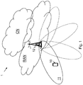
- Figure 1 is a schematic overview depicting a wireless communication network 1.
- the wireless communication network 1 comprises one or more RANs and one or more CNs.
- the wireless communication network 1 may use a number of different technologies, such as Wi-Fi, LTE, LTE-Advanced, New Radio (NR), 5G, WCDMA, GSM/enhanced Data rate for GSM Evolution (EDGE), Worldwide Interoperability for Microwave Access (WiMax), or Ultra Mobile Broadband (UMB), just to mention a few possible implementations.
- Embodiments herein relate to recent technology trends that are of particular interest in a 5G context, however, embodiments are also applicable in further development of the existing wireless communication systems such as e.g. WCDMA and LTE.
- wireless devices e.g. a wireless device 10 such as a mobile station, a non-access point (non-AP) STA, a STA, a user equipment and/or a wireless terminals, may communicate via one or more Access Networks (AN), e.g. RAN, with one or more core networks (CN).
- AN e.g. RAN
- CN core networks
- wireless device is a non-limiting term which means any terminal, wireless communication terminal, user equipment, Machine Type Communication (MTC) device, Device to Device (D2D) terminal, or node e.g. smart phone, laptop, mobile phone, sensor, relay, mobile tablets or even a small base station communicating within a cell.
- MTC Machine Type Communication
- D2D Device to Device
- the wireless communication network 1 comprises a radio-network node 12 providing radio coverage over a geographical area, a service area 11, which may also be referred to as a beam or a beam group, of a first radio access technology (RAT), such as NR, 5G, LTE, Wi-Fi or similar.
- the radio-network node 12 may be a transmission and reception point e.g. a radio access network node such as a Wireless Local Area Network (WLAN) access point or an Access Point Station (AP STA), an access controller, a base station, e.g.
- WLAN Wireless Local Area Network
- AP STA Access Point Station
- a radio base station such as a NodeB, an evolved Node B (eNB, eNode B), a base transceiver station, a radio remote unit, an Access Point Base Station, a base station router, a transmission arrangement of a radio base station, a stand-alone access point or any other network unit capable of communicating with a wireless device within the service area served by the radio-network node 12 depending e.g. on the first radio access technology and terminology used.
- the radio-network node 12 may be referred to as a serving radio-network node and communicates with the wireless device 10 with Downlink (DL) transmissions to the wireless device 10 and Uplink (UL) transmissions from the wireless device 10.
- DL Downlink
- UL Uplink
- UL scheduling and DL feedback information such as DL HARQ messages, transmitted in UL are decoupled. This means that previously the UL scheduling is handled via an UL grant from the radio-network node 12 while the scheduling of the DL HARQ is governed by a fixed timing that mandates it to be transmitted 4 subframes after a corresponding DL data transmission has been received.
- HARQ transmissions may take place over the PUCCH if no PUSCH transmission is scheduled. However, if PUSCH is scheduled, the HARQ transmission is instead moved to the PUSCH where it is punctured "on top of" UL data such as PUSCH data. The puncturing destroys some of the PUSCH transmission bits, but it is likely that the PUSCH transmission bits may still be recovered through error-correcting mechanisms.
- the reason for using puncturing rather than multiplexing is that it avoids the problem of the wireless device 10 misses receiving a grant for the UL data transmission or misses receiving a Downlink Control information (DCI) for the DL data transmission. If one or the other is missed i.e. not received or not decoded correctly, the decoding at the radio-network node would fail if the information was multiplexed since the wireless device and the radio-network node would be in disagreement as to what was actually contained in the transmission.
- DCI Downlink Control information
- the wireless device 10 may comprise data for transmission to the radio-network node 12.
- the radio-network node 12 schedules one or more resources for the wireless device 10 for carrying the transmission of an UL data transmission from the wireless device 10, and for carrying feedback transmission, of a DL data transmission from the radio-network node 12, from the wireless device 10. Information regarding the scheduling is then transmitted to the wireless device 10.
- the wireless device 10 provides the UL data transmission and feedback information, e.g. HARQ feedback, of the DL data transmission, data over e.g. a PDSCH, from the radio-network node 12.
- the feedback information may be transmitted as part of the Uplink Control Information (UCI) on PUSCH as scheduled by the radio-network node 12.
- UCI Uplink Control Information
- the UL data and the feedback information may be multiplexed e.g. into the PUSCH and transmitted to the radio-network node 12.
- embodiments herein provide a mechanism that efficiently sets up the configuration of the feedback information when providing scheduling information for UL data transmission from the wireless device 10.
- Embodiments herein introduce no bit errors to e.g. the PUSCH by the HARQ transmission since there is no puncturing, and there is no problem with missed grants that could cause a multiplexing scheme to fail since both UL data and feedback information are scheduled in the same UL grant or same control message.
- Fig. 2 is a combined flowchart and signaling scheme according to embodiments herein. Actions may be performed in any suitable order.
- the wireless device 10 has data intended for the radio-network node 12 or for transmission to another node or wireless device.
- the wireless device 10 may then transmit an UL data request, marked with a dashed arrow, when data are buffered for transmission at the wireless device 10.
- the wireless device 10 may alternatively or additionally receive a request from the radio-network node 12 requesting the UL data transmission from the wireless device 10.
- the radio-network node 12 schedules one or more resources, such as subframes, resource elements, resource blocks, symbols of frequencies, for carrying the UL data transmission over a channel such as PUSCH from the wireless device 10. Furthermore, the radio-network node 12 schedules one or more resources for carrying, from the wireless device 10, the feedback transmission of a DL data transmission from the radio-network node 12.
- resources such as subframes, resource elements, resource blocks, symbols of frequencies
- the radio-network node 12 then transmits the control message or information, such as an UL grant, indicating the scheduling of the one or more resources for carrying the UL data transmission over the channel from the wireless device 10.
- the same control message further indicates the scheduling of the one or more resources for the feedback transmission of the DL data transmission from the radio-network node 12.
- the UL data transmission and feedback transmission is carried over the same channel such as the PUSCH.
- embodiments herein disclose the transmission of the scheduling of the feedback such as UCI and UL data in one UL grant.
- Feedback indicators of the feedback information may comprise one bit to indicate that the ACK/NACK is present and where, which resource elements, it is present may be given by standard.
- the feedback indicators such as ACK/NACK
- the feedback indicators are mapped to resources such as resource elements closest to demodulation reference signals so that the quality of the channel estimates is best for ACK/NACK, which is more important than other types of UCI, e.g. Channel Quality Indicator (CQI) and Rank Indicator (RI).
- CQI Channel Quality Indicator
- RI Rank Indicator
- a scheduling command in the control message for inclusion of ACK or NACK, is more than one bit, and allows not only indicating presence of the feedback indicators but additionally placing the feedback indicators in a subband of a whole scheduled frequency band. So the feedback information or indicators do not have the same transmission bandwidth as the UL data transmission.
- a scheduler in the radio-network node 12 can place resources for the feedback transmission in the subband out of several possible subbands, for which the channel fading in frequency domain is favourable, a so-called fading peak. The benefit is better reception and more robustness of the feedback information.
- embodiments herein may enable a PUSCH transmission that may be rate-matched to available resources, meaning that the coding rate, i.e., the amount of redundancy added, is adapted to suit the expected channel conditions, e.g. Signal to Interference plus Noise Ratio (SINR), and number of bits available for the transmission to yield a target error probability.
- SINR Signal to Interference plus Noise Ratio
- the radio-network node 12 may transmit DL data in a DL data transmission to the wireless device 10.
- the wireless device 10 attempts to decode the received DL data and generates feedback information regarding the decoding e.g. ACK in case of successful decoding, NACK in case of unsuccessful decoding of data and Discontinuous transmission (DTX), i.e. no transmission, in case of unsuccessful decoding of control information i.e. not detecting a DL grant for the DL data transmission.
- ACK in case of successful decoding
- NACK in case of unsuccessful decoding of data
- DTX Discontinuous transmission
- control information i.e. not detecting a DL grant for the DL data transmission.
- the wireless device 10 then transmits UL data and generated feedback information as scheduled in the control message over the same channel, e.g. the PUSCH.
- the radio-network node 12 may read the feedback information based on knowledge of the scheduled one or more resources for the feedback.
- the radio-network node 12 further also reads the UL data transmission.
- the radio-network node 12 determines whether to retransmit any DL data based on the read feedback.
- Fig. 3 is a flowchart depicting a method performed by the radio-network node 12 for handling a data transmission, such as transmission of data over a subframe, from the wireless device 10 to the radio-network node 12 in the wireless communication network 1.
- Actions may be performed in any suitable order and optional actions are marked as dashed boxes.
- the radio-network node 12 may receive the UL data request from the wireless device 10 or UL data may be requested from the radio-network node 12, e.g. requesting measurement data from the wireless device or similar.
- the radio-network node 12 schedules one or more resources for carrying the uplink data transmission from the wireless device 10 over the channel, such as the PUSCH, and for carrying the feedback transmission, of the downlink data transmission from the radio-network node 12, over the same channel.
- the radio-network node 12 transmits the control message to the wireless device 10.
- the control message indicates the one or more resources scheduled for carrying the uplink data transmission and the feedback transmission over the same channel.
- the control message indicates the scheduling of resources for carrying the data transmission over the channel from the wireless device 10, and the control message further indicates the scheduling of resources for feedback transmission of the data transmission, DL data, from the radio-network node 12 over the same channel.
- the control message may be an uplink grant.
- the radio-network node 12 may then read the feedback information received over the channel as scheduled.
- the radio-network node 12 may then determine based on the read feedback information whether to retransmit DL data of the downlink data transmission or not.
- Fig. 4 is a flowchart depicting a method performed by the wireless device 10 for handling the data transmission, UL data, to the radio-network node 12 in the wireless communication network 1. Actions may be performed in any suitable order and optional actions are marked as dashed boxes.
- the wireless device 10 may have data intended for the radio-network node 12 or for transmission to another node or wireless device.
- the wireless device 10 may then transmit the UL data request, e.g. an UL Scheduling Request (SR), to the radio-network node 12 indicating UL data transmission from the wireless device 10.
- SR UL Scheduling Request
- the UL data transmission may also be requested from the radio-network node 12.
- the wireless device 10 receives from the radio-network node 12, the control message, which control message indicates the one or more resources scheduled for carrying the uplink data transmission over the channel and the feedback transmission over the same channel, which feedback transmission is for the downlink data transmission from the radio-network node 12.
- the control message may be an UL grant, and the control message may indicate the scheduling of resources for carrying the data transmission over the channel from the wireless device 10.
- the control message may further indicate the scheduling of resources for feedback transmission, over the channel, of one or more data transmissions from the radio-network node 12.
- the wireless device 10 may receive the DL data transmission from the radio-network node 12, e.g. a number of subframes carrying data information and control information/parts.
- the wireless device 10 may generate feedback information of the received data transmission for the feedback transmission e.g. add feedback indicators into a feedback message.
- the wireless device 10 performs the uplink data transmission and the feedback transmission to the radio-network node 12 over the same channel using the one or more resources indicated in the control message. Thus, the wireless device 10 transmits the UL data to the radio-network node 12 as scheduled and also the feedback, e.g. feedback indicator, of the DL data transmission as scheduled in the control message to the radio-network node 12.
- the wireless device 10 may perform the uplink data transmission and the feedback transmission to the radio-network node 12 by multiplexing the feedback information with uplink data of the uplink data transmission over the same channel e.g. multiplexing feedback indicators/information, with UL data over the channel such as a shared channel e.g. the PUSCH.
- Fig. 5 is a block diagram depicting the radio-network node 12, in two embodiments, for handling a data transmission, such as an UL data transmission of data over a subframe, from the wireless device 10 to the radio-network node 12 in the wireless communication network 1.
- a data transmission such as an UL data transmission of data over a subframe
- the radio-network node 12 may comprise a processing unit 501, e.g. one or more processors, configured to perform the methods herein.
- a processing unit 501 e.g. one or more processors, configured to perform the methods herein.
- the radio-network node 12 may comprise a receiving module 502, e.g. a receiver or transceiver.
- the radio-network node 12, the processing unit 501, and/or the receiving module 502 may be configured to receive the UL scheduling request from the wireless device 10.
- the radio-network node 12 may comprise a scheduling module 503, e.g. a scheduler.
- the radio-network node 12, the processing unit 501, and/or the scheduling module 503 is configured to schedule one or more resources for carrying the uplink data transmission from the wireless device 10 over the channel, and for carrying the feedback transmission, of the downlink data transmission from the radio-network node, over the same channel.
- the radio-network node 12 may comprise a transmitting module 504, e.g. a transmitter or transceiver.
- the radio-network node 12, the processing unit 501, and/or the transmitting module 504 is configured to transmit the control message to the wireless device 10, which control message indicates the one or more resources scheduled for carrying the uplink data transmission and the feedback transmission over the same channel.
- the control message may be an uplink grant and the channel may be the PUSCH.
- the radio-network node 12 may comprise a reading module 505.
- the radio-network node 12, the processing unit 501, and/or the reading module 505 may be configured to read the feedback information received over the channel as scheduled.
- the radio-network node 12 may comprise a determining module 506.
- the radio-network node 12, the processing unit 501, and/or the determining module 506 may be configured to determine, based on the read feedback information, whether to retransmit downlink data of the downlink data transmission or not.
- the methods according to the embodiments described herein for the radio-network node 12 are respectively implemented by means of e.g. a computer program 507 or a computer program product, comprising instructions, i.e., software code portions, which, when executed on at least one processor, cause the at least one processor to carry out the actions described herein, as performed by the radio-network node 12.
- the computer program 507 may be stored on a computer-readable storage medium 508, e.g. a disc, a USB or similar.
- the computer-readable storage medium 508, having stored thereon the computer program may comprise the instructions which, when executed on at least one processor, cause the at least one processor to carry out the actions described herein, as performed by the radio-network node 12.
- the computer-readable storage medium may be a non-transitory computer-readable storage medium.
- the radio-network node 12 further comprises a memory 509.
- the memory comprises one or more units to be used to store data on, such as feedback indicators, resources, SRs, DL data, UL Grants, applications to perform the methods disclosed herein when being executed, and similar.
- the first radio-network node 12 for handling the data transmission, from the wireless device 10 to the radio-network node 12, in the wireless communication network 1 may herein be provided wherein the memory 509 contains instructions executable by said processing unit 501 whereby the first radio-network node 12 is operative to perform the methods herein.
- Fig. 6 is a block diagram depicting the wireless device 10, in two embodiments, for handling the data transmission, UL data, to the radio-network node 12 in the wireless communication network 1.
- the wireless device 10 may comprise a processing unit 601, e.g. one or more processors, configured to perform the methods herein.
- a processing unit 601 e.g. one or more processors, configured to perform the methods herein.
- the wireless device 10 may comprise a transmitting module 602 e.g. a transmitter or transceiver.
- the wireless device 10, the processing unit 601, and/or the transmitting module 602 may be configured to transmit, when the wireless device 10 has data intended for the radio-network node 12 or for transmission to another node or wireless device, the UL data request, e.g. an SR, to the radio-network node 12 indicating UL data transmission from the wireless device 10.
- the UL data request e.g. an SR
- the wireless device 10 may comprise a receiving module 603, e.g. a receiver or transceiver.
- the wireless device 10, the processing unit 601, and/or the receiving module 603 is configured to receive the control message, from the radio-network node 12, which control message indicates the one or more resources scheduled for carrying the uplink data transmission over the channel and the feedback transmission over the same channel.
- the feedback transmission is for the downlink data transmission from the radio-network node 12.
- the control message may indicate scheduling of resources for carrying the data transmission over the channel from the wireless device 10.
- the control message may indicate the scheduling of resources for feedback transmission, over the channel, of one or more data transmissions from the radio-network node 12.
- the wireless device 10, the processing unit 601, and/or the receiving module 603 may be configured to receive the DL data transmission from the radio-network node 12, e.g. a number of subframes carrying data information and control parts/information.
- the wireless device 10 may comprise a generating module 604.
- the wireless device 10, the processing unit 601, and/or the generating module 604 may be configured to generate feedback information of the received data transmission for the feedback transmission e.g. add feedback indicators into the feedback message.
- the wireless device 10 may comprise a multiplexing module 605.
- the wireless device 10, the processing unit 601, and/or the multiplexing module 605 may be configured to multiplex the feedback e.g. feedback indicators/information, with UL data over the channel such as the shared channel e.g. the PUSCH.
- the wireless device 10, the processing unit 601, and/or the multiplexing module 605 may be configured to perform the uplink data transmission and the feedback transmission by being configured to multiplex the feedback information with uplink data of the uplink data transmission over the same channel.
- the wireless device 10, the processing unit 601, and/or the transmitting module 602 is configured to perform the uplink data transmission and the feedback transmission to the radio-network node 12 over the same channel using the one or more resources indicated in the control message.
- the wireless device 10, the processing unit 601, and/or the transmitting module 602 may be configured to transmit the UL data to the radio-network node 12 as scheduled and also the feedback, e.g. feedback indicator, of the DL data transmission as scheduled in the control message to the radio-network node 12.
- the channel may be the physical uplink shared channel and the control message may be an uplink grant.
- the methods according to the embodiments described herein for the wireless device 10 are respectively implemented by means of e.g. a computer program 606 or a computer program product, comprising instructions, i.e., software code portions, which, when executed on at least one processor, cause the at least one processor to carry out the actions described herein, as performed by the wireless device 10.
- the computer program 606 may be stored on a computer-readable storage medium 607, e.g. a disc, a USB, or similar.
- the computer-readable storage medium 607, having stored thereon the computer program may comprise the instructions which, when executed on at least one processor, cause the at least one processor to carry out the actions described herein, as performed by the wireless device 10.
- the computer-readable storage medium may be a non-transitory computer-readable storage medium.
- the the wireless device 10 further comprises a memory 608.
- the memory comprises one or more units to be used to store data on, such as feedback indicators, resources, multiplexing, SRs, reference signals, UL data, applications to perform the methods disclosed herein when being executed, and similar.
- the wireless device 10 for handling the data transmission, UL data, to the radio-network node 12 in the wireless communication network 1 may herein be provided wherein the memory 608 contains instructions executable by said processing unit 601 whereby the wireless device 10 is operative to perform the methods herein.
- ASIC application-specific integrated circuit
- Several of the functions may be implemented on a processor shared with other functional components of a radio-network node, for example.
- processors or “controller” as used herein does not exclusively refer to hardware capable of executing software and may implicitly include, without limitation, digital signal processor (DSP) hardware, read-only memory (ROM) for storing software, random-access memory for storing software and/or program or application data, and non-volatile memory.
- DSP digital signal processor
- ROM read-only memory
- RAM random-access memory
- non-volatile memory non-volatile memory
- a radio-network node for handling a data transmission, such as transmission of data over a subframe, from a wireless device to the radio-network node in a wireless communication network.
- the radio-network node transmits a control message, such as an UL grant, indicating scheduling of resources for carrying the data transmission over a channel from the wireless device, and which control message further indicates a scheduling of resources, over the same channel, for feedback transmission of a data transmission from the radio-network node.
- a method performed by a wireless device for handling a data transmission to a radio-network node in a wireless communication network receives a control message, from the radio-network node, which control message indicates scheduling of resources for carrying the data transmission over a channel from the wireless device, and which control message further indicates a scheduling of resources for feedback transmission, over the channel, of a data transmission from the radio-network node.
- the wireless device then transmits the data to the radio-network node as scheduled and also a feedback indicator of a DL data transmission as scheduled to the radio-network node.
- radio-network node and a wireless device configured to perform the methods herein are also provided.
- a computer program comprising instructions, which, when executed on at least one processor, cause the at least one processor to carry out any of the methods above, as performed by the radio-network node or the wireless device.
- a computer-readable storage medium having stored thereon a computer program comprising instructions which, when executed on at least one processor, cause the at least one processor to carry out the method according to any of the methods above, as performed by the radio-network node or the wireless device.
Description
- Embodiments herein relate to a radio-network node, a wireless device and methods performed therein for wireless communication. Furthermore, a computer program and a computer-readable storage medium are also provided herein. In particular, embodiments herein relate to handling communication of data, such as data transmission to the radio-network node, in a wireless communication network.
- In a typical wireless communication network, wireless devices, also known as wireless communication devices, mobile stations, stations (STA) and/or user equipments (UE), communicate via a Radio Access Network (RAN) with one or more core networks (CN). The RAN covers a geographical area which is divided into service areas or cell areas, which may also be referred to as a beam or a beam group, with each service area or cell area being served by a radio-network node such as a radio access node e.g., a Wi-Fi access point or a radio base station (RBS), which in some networks may also be denoted, for example, a "NodeB" or "eNodeB". A service area or cell area is a geographical area where radio coverage is provided by the radio-network node. The radio-network node communicates over an air interface operating on radio frequencies with a wireless device within range of the radio-network node.
- A Universal Mobile Telecommunications System (UMTS) is a third generation (3G) telecommunication network, which evolved from the second generation (2G) Global System for Mobile Communications (GSM). The UMTS terrestrial radio access network (UTRAN) is essentially a RAN using wideband code division multiple access (WCDMA) and/or High Speed Packet Access (HSPA) for user equipments. In a forum known as the Third Generation Partnership Project (3GPP), telecommunications suppliers propose and agree upon standards for third generation networks, and investigate enhanced data rate and radio capacity. In some RANs, e.g. as in UMTS, a plurality of radio-network nodes may be connected, e.g., by landlines or microwave, to a controller node, such as a radio-network controller (RNC) or a base station controller (BSC), which supervises and coordinates various activities of the plurality of radio-network nodes connected thereto. This type of connection is sometimes referred to as a backhaul connection. The RNCs and BSCs are typically connected to one or more core networks.
- Specifications for Evolved Packet System (EPS), also called a Fourth Generation (4G) network, have been completed within 3GPP and this work continues in the coming 3GPP releases, for example to specify a Fifth Generation (5G) network. The EPS comprises the Evolved Universal Terrestrial Radio Access Network (E-UTRAN), also known as the Long Term Evolution (LTE) radio access network, and the Evolved Packet Core (EPC), also known as System Architecture Evolution (SAE) core network. E-UTRAN/LTE is a variant of a 3GPP radio access network wherein the radio-network nodes are directly connected to the EPC core network rather than to RNCs. In general, in E-UTRAN/LTE the functions of an RNC are distributed between the radio-network nodes, e.g. eNodeBs in LTE, and the core network. As such, the RAN of an EPS has an essentially "flat" architecture comprising radio-network nodes connected directly to one or more core networks, i.e. they are not connected to RNCs. To compensate for that, the E-UTRAN specification defines a direct interface between the radio-network nodes, this interface being denoted the X2 interface. EPS is the Evolved 3GPP Packet Switched Domain.
- Advanced Antenna Systems (AASs) is an area where technology has advanced significantly in recent years and where a rapid technology development in the years to come is foreseen. Hence it is natural to assume that AASs in general and massive Multiple Input Multiple Output (MIMO) transmission and reception in particular will be a cornerstone in a future Fifth Generation (5G) system.
- In relation to AAS, beam-forming is becoming increasingly popular and capable and it is not only for transmission of data but also for transmission of control information. This is one motivation behind a control channel in LTE known as Enhanced Physical Downlink Control Channel (ePDCCH). When the control channel is beam-formed, the cost of transmitting the overhead control information can be reduced due to the increased link budget provided by the additional antenna gain.
- Automatic repeat-request (ARQ) is an error-control technique used in many wireless networks. With ARQ, a receiver of data transmissions sends acknowledgements (ACKs) or negative acknowledgments (NACKs) to inform the transmitter of whether each message has been correctly received. Incorrectly received messages, as well as messages that aren't acknowledged at all, can then be re-transmitted.
- Hybrid ARQ (HARQ) combines ARQ with forward error-correction (FEC) coding of the data messages, to improve the ability of the receiver to receive and correctly decode the transmitted messages. As with conventional ARQ, receivers employing HARQ send ACKs and NACKs, as appropriate, after each attempt to decode a message. These ACKs and NACKs are referred to as "HARQ feedback".
- For downlink HARQ transmissions in LTE today, HARQ feedback is sent from the wireless device, e.g. a User Equipment (UE) to the Network (NW) on either Physical Uplink Control Channel (PUCCH) or Physical Uplink Shared Channel (PUSCH), depending on whether the wireless device has been scheduled for an uplink PUSCH transmission or not. The NW can thereafter, on an individual HARQ process basis, draw conclusions on whether the last HARQ reception for that process was successful or not, based on received ACK or NACK, or even if the Downlink (DL) Assignment reception failed, i.e. the wireless device does not send any feedback also called Discontinuous Transmission (DTX).
- The timing of the transmitted HARQ feedback in LTE is such that, for Frequency Division Duplexing (FDD), the feedback from one HARQ Receive (RX) process is received in the Uplink (UL) in subframe n + 4 if the corresponding DL data transmission for that process was in subframe n, corresponding to 4 milliseconds (ms) in total. For Time Division Duplexing (TDD), the delay from DL data transmission to UL feedback reception may be larger than four to cater for the half-duplex DL-UL split.
- Providing feedback as in prior art may limit the performance of the wireless communication network.
-
US 2011/092240 A1 andUS 2013/039321 A1 show the use of puncturing to provide feedback. This has the drawback that part of the uplink data bits will be destroyed by the feedback transmission. - An object herein is to provide a mechanism that enhances performance of the wireless communication network according to the appended claims.
- According to embodiments herein the object is achieved by providing a method performed by a radio-network node for handling a data transmission, from a wireless device to the radio-network node, in a wireless communication network. The radio-network node schedules one or more resources for carrying an uplink data transmission from the wireless device over a channel, and for carrying a feedback transmission, of a downlink data transmission from the radio-network node, over the same channel. The radio-network node further transmits a control message to the wireless device, which control message indicates the one or more resources scheduled for carrying the uplink data transmission and the feedback transmission over the same channel.
- According to embodiments herein the object is also achieved by providing a method performed by a wireless device for handling a data transmission to a radio-network node in a wireless communication network. The wireless device receives, from the radio-network node, a control message, which control message indicates one or more resources scheduled for carrying an uplink data transmission over a channel and a feedback transmission over the same channel. The feedback transmission is for a downlink data transmission from the radio-network node. The wireless device performs the uplink data transmission and the feedback transmission to the radio-network node over the same channel using the one or more resources indicated in the control message.
- According to embodiments herein the object is additionally achieved by providing a radio-network node for handling a data transmission, from a wireless device to the radio-network node, in a wireless communication network. The radio-network node is configured to schedule one or more resources for carrying an uplink data transmission from the wireless device over a channel, and for carrying a feedback transmission, of a downlink data transmission from the radio-network node, over the same channel. The radio-network node is further configured to transmit a control message to the wireless device, which control message indicates the one or more resources scheduled for carrying the uplink data transmission and the feedback transmission over the same channel.
- According to embodiments herein the object is additionally achieved by providing a wireless device for handling a data transmission to a radio-network node in a wireless communication network. The wireless device is configured to receive, from the radio-network node, a control message, which control message indicates one or more resources scheduled for carrying an uplink data transmission over a channel and a feedback transmission over the same channel, which feedback transmission is for a downlink data transmission from the radio-network node. The wireless device is further configured to perform the uplink data transmission and the feedback transmission to the radio-network node over the same channel using the one or more resources indicated in the control message.
- It is furthermore provided herein a computer program comprising instructions, which, when executed on at least one processor, cause the at least one processor to carry out any of the methods above, as performed by the radio-network node or the wireless device. It is additionally provided herein a computer-readable storage medium, having stored thereon a computer program comprising instructions which, when executed on at least one processor, cause the at least one processor to carry out the method according to any of the methods above, as performed by the radio-network node or the wireless device.
- Embodiments herein provide a manner of enabling feedback of the DL data transmission to the radio-network node in an efficient manner. By scheduling the UL data transmission and the feedback transmission in a same control message, e.g. control information or control part of a message such as same UL grant, the feedback is provided back to the radio-network node in an efficient manner leading to an improved performance of the wireless communication network. Embodiments herein introduce no bit errors to the channel, such as PUSCH, by the feedback transmission since there is no puncturing. Problems with missed grants that could cause a multiplexing scheme to fail are also avoided since both the UL data transmission and the feedback transmission are scheduled in the same control message.
- Embodiments will now be described in more detail in relation to the enclosed drawings, in which:
- Fig. 1
- is an overview depicting a wireless communication network according to embodiments herein;
- Fig. 2
- is a combined flowchart and signalling scheme according to embodiments herein;
- Fig. 3
- is a schematic flowchart depicting a method performed by a radio-network node according to embodiments herein;
- Fig. 4
- is a schematic flowchart depicting a method performed by a wireless device according to embodiments herein;
- Fig. 5
- is a block diagram depicting a radio-network node according to embodiments herein; and
- Fig. 6
- is a block diagram depicting a wireless device according to embodiments herein.
- Embodiments herein relate to wireless communication networks in general.
Figure 1 is a schematic overview depicting awireless communication network 1. Thewireless communication network 1 comprises one or more RANs and one or more CNs. Thewireless communication network 1 may use a number of different technologies, such as Wi-Fi, LTE, LTE-Advanced, New Radio (NR), 5G, WCDMA, GSM/enhanced Data rate for GSM Evolution (EDGE), Worldwide Interoperability for Microwave Access (WiMax), or Ultra Mobile Broadband (UMB), just to mention a few possible implementations. Embodiments herein relate to recent technology trends that are of particular interest in a 5G context, however, embodiments are also applicable in further development of the existing wireless communication systems such as e.g. WCDMA and LTE. - In the
wireless communication network 1, wireless devices e.g. awireless device 10 such as a mobile station, a non-access point (non-AP) STA, a STA, a user equipment and/or a wireless terminals, may communicate via one or more Access Networks (AN), e.g. RAN, with one or more core networks (CN). It should be understood by the skilled in the art that "wireless device" is a non-limiting term which means any terminal, wireless communication terminal, user equipment, Machine Type Communication (MTC) device, Device to Device (D2D) terminal, or node e.g. smart phone, laptop, mobile phone, sensor, relay, mobile tablets or even a small base station communicating within a cell. - The
wireless communication network 1 comprises a radio-network node 12 providing radio coverage over a geographical area, aservice area 11, which may also be referred to as a beam or a beam group, of a first radio access technology (RAT), such as NR, 5G, LTE, Wi-Fi or similar. The radio-network node 12 may be a transmission and reception point e.g. a radio access network node such as a Wireless Local Area Network (WLAN) access point or an Access Point Station (AP STA), an access controller, a base station, e.g. a radio base station such as a NodeB, an evolved Node B (eNB, eNode B), a base transceiver station, a radio remote unit, an Access Point Base Station, a base station router, a transmission arrangement of a radio base station, a stand-alone access point or any other network unit capable of communicating with a wireless device within the service area served by the radio-network node 12 depending e.g. on the first radio access technology and terminology used. The radio-network node 12 may be referred to as a serving radio-network node and communicates with thewireless device 10 with Downlink (DL) transmissions to thewireless device 10 and Uplink (UL) transmissions from thewireless device 10. - As part of developing embodiments herein a problem has been identified. In e.g. LTE, UL scheduling and DL feedback information, such as DL HARQ messages, transmitted in UL are decoupled. This means that previously the UL scheduling is handled via an UL grant from the radio-
network node 12 while the scheduling of the DL HARQ is governed by a fixed timing that mandates it to be transmitted 4 subframes after a corresponding DL data transmission has been received. - HARQ transmissions may take place over the PUCCH if no PUSCH transmission is scheduled. However, if PUSCH is scheduled, the HARQ transmission is instead moved to the PUSCH where it is punctured "on top of" UL data such as PUSCH data. The puncturing destroys some of the PUSCH transmission bits, but it is likely that the PUSCH transmission bits may still be recovered through error-correcting mechanisms.
- The reason for using puncturing rather than multiplexing is that it avoids the problem of the
wireless device 10 misses receiving a grant for the UL data transmission or misses receiving a Downlink Control information (DCI) for the DL data transmission. If one or the other is missed i.e. not received or not decoded correctly, the decoding at the radio-network node would fail if the information was multiplexed since the wireless device and the radio-network node would be in disagreement as to what was actually contained in the transmission. - According to embodiments herein the
wireless device 10 may comprise data for transmission to the radio-network node 12. The radio-network node 12 schedules one or more resources for thewireless device 10 for carrying the transmission of an UL data transmission from thewireless device 10, and for carrying feedback transmission, of a DL data transmission from the radio-network node 12, from thewireless device 10. Information regarding the scheduling is then transmitted to thewireless device 10. - The
wireless device 10 provides the UL data transmission and feedback information, e.g. HARQ feedback, of the DL data transmission, data over e.g. a PDSCH, from the radio-network node 12. The feedback information may be transmitted as part of the Uplink Control Information (UCI) on PUSCH as scheduled by the radio-network node 12. E.g. the UL data and the feedback information may be multiplexed e.g. into the PUSCH and transmitted to the radio-network node 12. - Thus, embodiments herein provide a mechanism that efficiently sets up the configuration of the feedback information when providing scheduling information for UL data transmission from the
wireless device 10. Embodiments herein introduce no bit errors to e.g. the PUSCH by the HARQ transmission since there is no puncturing, and there is no problem with missed grants that could cause a multiplexing scheme to fail since both UL data and feedback information are scheduled in the same UL grant or same control message. -
Fig. 2 is a combined flowchart and signaling scheme according to embodiments herein. Actions may be performed in any suitable order. -
Action 201. Thewireless device 10 has data intended for the radio-network node 12 or for transmission to another node or wireless device. Thewireless device 10 may then transmit an UL data request, marked with a dashed arrow, when data are buffered for transmission at thewireless device 10. Thewireless device 10 may alternatively or additionally receive a request from the radio-network node 12 requesting the UL data transmission from thewireless device 10. -
Action 202. The radio-network node 12 schedules one or more resources, such as subframes, resource elements, resource blocks, symbols of frequencies, for carrying the UL data transmission over a channel such as PUSCH from thewireless device 10. Furthermore, the radio-network node 12 schedules one or more resources for carrying, from thewireless device 10, the feedback transmission of a DL data transmission from the radio-network node 12. -
Action 203. The radio-network node 12 then transmits the control message or information, such as an UL grant, indicating the scheduling of the one or more resources for carrying the UL data transmission over the channel from thewireless device 10. The same control message further indicates the scheduling of the one or more resources for the feedback transmission of the DL data transmission from the radio-network node 12. The UL data transmission and feedback transmission is carried over the same channel such as the PUSCH. Thus, embodiments herein disclose the transmission of the scheduling of the feedback such as UCI and UL data in one UL grant. Feedback indicators of the feedback information may comprise one bit to indicate that the ACK/NACK is present and where, which resource elements, it is present may be given by standard. - In some embodiments, the feedback indicators such as ACK/NACK, when present, are mapped to resources such as resource elements closest to demodulation reference signals so that the quality of the channel estimates is best for ACK/NACK, which is more important than other types of UCI, e.g. Channel Quality Indicator (CQI) and Rank Indicator (RI). The data is then rate matched, i.e. mapped around these resource elements, to avoid the resource elements used for the feedback indicators.
- In some embodiments, a scheduling command in the control message, for inclusion of ACK or NACK, is more than one bit, and allows not only indicating presence of the feedback indicators but additionally placing the feedback indicators in a subband of a whole scheduled frequency band. So the feedback information or indicators do not have the same transmission bandwidth as the UL data transmission. By doing this, a scheduler in the radio-
network node 12 can place resources for the feedback transmission in the subband out of several possible subbands, for which the channel fading in frequency domain is favourable, a so-called fading peak. The benefit is better reception and more robustness of the feedback information. - Thus, embodiments herein may enable a PUSCH transmission that may be rate-matched to available resources, meaning that the coding rate, i.e., the amount of redundancy added, is adapted to suit the expected channel conditions, e.g. Signal to Interference plus Noise Ratio (SINR), and number of bits available for the transmission to yield a target error probability.
-
Action 204. The radio-network node 12 may transmit DL data in a DL data transmission to thewireless device 10. -
Action 205. Thewireless device 10 attempts to decode the received DL data and generates feedback information regarding the decoding e.g. ACK in case of successful decoding, NACK in case of unsuccessful decoding of data and Discontinuous transmission (DTX), i.e. no transmission, in case of unsuccessful decoding of control information i.e. not detecting a DL grant for the DL data transmission. -
Action 206. Thewireless device 10 then transmits UL data and generated feedback information as scheduled in the control message over the same channel, e.g. the PUSCH. -
Action 207. The radio-network node 12 may read the feedback information based on knowledge of the scheduled one or more resources for the feedback. The radio-network node 12 further also reads the UL data transmission. -
Action 208. The radio-network node 12 then determines whether to retransmit any DL data based on the read feedback. -
Fig. 3 is a flowchart depicting a method performed by the radio-network node 12 for handling a data transmission, such as transmission of data over a subframe, from thewireless device 10 to the radio-network node 12 in thewireless communication network 1. Actions may be performed in any suitable order and optional actions are marked as dashed boxes. -
Action 301. The radio-network node 12 may receive the UL data request from thewireless device 10 or UL data may be requested from the radio-network node 12, e.g. requesting measurement data from the wireless device or similar. -
Action 302. The radio-network node 12 schedules one or more resources for carrying the uplink data transmission from thewireless device 10 over the channel, such as the PUSCH, and for carrying the feedback transmission, of the downlink data transmission from the radio-network node 12, over the same channel. -
Action 303. The radio-network node 12 transmits the control message to thewireless device 10. The control message indicates the one or more resources scheduled for carrying the uplink data transmission and the feedback transmission over the same channel. Hence, the control message indicates the scheduling of resources for carrying the data transmission over the channel from thewireless device 10, and the control message further indicates the scheduling of resources for feedback transmission of the data transmission, DL data, from the radio-network node 12 over the same channel. The control message may be an uplink grant. -
Action 304. The radio-network node 12 may then read the feedback information received over the channel as scheduled. -
Action 305. The radio-network node 12 may then determine based on the read feedback information whether to retransmit DL data of the downlink data transmission or not. -
Fig. 4 is a flowchart depicting a method performed by thewireless device 10 for handling the data transmission, UL data, to the radio-network node 12 in thewireless communication network 1. Actions may be performed in any suitable order and optional actions are marked as dashed boxes. -
Action 400. Thewireless device 10 may have data intended for the radio-network node 12 or for transmission to another node or wireless device. Thewireless device 10 may then transmit the UL data request, e.g. an UL Scheduling Request (SR), to the radio-network node 12 indicating UL data transmission from thewireless device 10. The UL data transmission may also be requested from the radio-network node 12. -
Action 401. Thewireless device 10 receives from the radio-network node 12, the control message, which control message indicates the one or more resources scheduled for carrying the uplink data transmission over the channel and the feedback transmission over the same channel, which feedback transmission is for the downlink data transmission from the radio-network node 12. The control message may be an UL grant, and the control message may indicate the scheduling of resources for carrying the data transmission over the channel from thewireless device 10. Furthermore, the control message may further indicate the scheduling of resources for feedback transmission, over the channel, of one or more data transmissions from the radio-network node 12. -
Action 402. Thewireless device 10 may receive the DL data transmission from the radio-network node 12, e.g. a number of subframes carrying data information and control information/parts. -
Action 403. Thewireless device 10 may generate feedback information of the received data transmission for the feedback transmission e.g. add feedback indicators into a feedback message. -
Action 404. Thewireless device 10 performs the uplink data transmission and the feedback transmission to the radio-network node 12 over the same channel using the one or more resources indicated in the control message. Thus, thewireless device 10 transmits the UL data to the radio-network node 12 as scheduled and also the feedback, e.g. feedback indicator, of the DL data transmission as scheduled in the control message to the radio-network node 12. Thewireless device 10 may perform the uplink data transmission and the feedback transmission to the radio-network node 12 by multiplexing the feedback information with uplink data of the uplink data transmission over the same channel e.g. multiplexing feedback indicators/information, with UL data over the channel such as a shared channel e.g. the PUSCH. -
Fig. 5 is a block diagram depicting the radio-network node 12, in two embodiments, for handling a data transmission, such as an UL data transmission of data over a subframe, from thewireless device 10 to the radio-network node 12 in thewireless communication network 1. - The radio-
network node 12 may comprise aprocessing unit 501, e.g. one or more processors, configured to perform the methods herein. - The radio-
network node 12 may comprise areceiving module 502, e.g. a receiver or transceiver. The radio-network node 12, theprocessing unit 501, and/or the receivingmodule 502 may be configured to receive the UL scheduling request from thewireless device 10. - The radio-
network node 12 may comprise ascheduling module 503, e.g. a scheduler. The radio-network node 12, theprocessing unit 501, and/or thescheduling module 503 is configured to schedule one or more resources for carrying the uplink data transmission from thewireless device 10 over the channel, and for carrying the feedback transmission, of the downlink data transmission from the radio-network node, over the same channel. - The radio-
network node 12 may comprise atransmitting module 504, e.g. a transmitter or transceiver. The radio-network node 12, theprocessing unit 501, and/or thetransmitting module 504 is configured to transmit the control message to thewireless device 10, which control message indicates the one or more resources scheduled for carrying the uplink data transmission and the feedback transmission over the same channel. The control message may be an uplink grant and the channel may be the PUSCH. - The radio-
network node 12 may comprise areading module 505. The radio-network node 12, theprocessing unit 501, and/or thereading module 505 may be configured to read the feedback information received over the channel as scheduled. - The radio-
network node 12 may comprise a determiningmodule 506. The radio-network node 12, theprocessing unit 501, and/or the determiningmodule 506 may be configured to determine, based on the read feedback information, whether to retransmit downlink data of the downlink data transmission or not. - The methods according to the embodiments described herein for the radio-
network node 12 are respectively implemented by means of e.g. acomputer program 507 or a computer program product, comprising instructions, i.e., software code portions, which, when executed on at least one processor, cause the at least one processor to carry out the actions described herein, as performed by the radio-network node 12. Thecomputer program 507 may be stored on a computer-readable storage medium 508, e.g. a disc, a USB or similar. The computer-readable storage medium 508, having stored thereon the computer program, may comprise the instructions which, when executed on at least one processor, cause the at least one processor to carry out the actions described herein, as performed by the radio-network node 12. In some embodiments, the computer-readable storage medium may be a non-transitory computer-readable storage medium. - The radio-
network node 12 further comprises amemory 509. The memory comprises one or more units to be used to store data on, such as feedback indicators, resources, SRs, DL data, UL Grants, applications to perform the methods disclosed herein when being executed, and similar. Thus, the first radio-network node 12 for handling the data transmission, from thewireless device 10 to the radio-network node 12, in thewireless communication network 1 may herein be provided wherein thememory 509 contains instructions executable by saidprocessing unit 501 whereby the first radio-network node 12 is operative to perform the methods herein. -
Fig. 6 is a block diagram depicting thewireless device 10, in two embodiments, for handling the data transmission, UL data, to the radio-network node 12 in thewireless communication network 1. - The
wireless device 10 may comprise aprocessing unit 601, e.g. one or more processors, configured to perform the methods herein. - The
wireless device 10 may comprise atransmitting module 602 e.g. a transmitter or transceiver. Thewireless device 10, theprocessing unit 601, and/or thetransmitting module 602 may be configured to transmit, when thewireless device 10 has data intended for the radio-network node 12 or for transmission to another node or wireless device, the UL data request, e.g. an SR, to the radio-network node 12 indicating UL data transmission from thewireless device 10. - The
wireless device 10 may comprise areceiving module 603, e.g. a receiver or transceiver. Thewireless device 10, theprocessing unit 601, and/or the receivingmodule 603 is configured to receive the control message, from the radio-network node 12, which control message indicates the one or more resources scheduled for carrying the uplink data transmission over the channel and the feedback transmission over the same channel. The feedback transmission is for the downlink data transmission from the radio-network node 12. The control message may indicate scheduling of resources for carrying the data transmission over the channel from thewireless device 10. Furthermore, the control message may indicate the scheduling of resources for feedback transmission, over the channel, of one or more data transmissions from the radio-network node 12. - The
wireless device 10, theprocessing unit 601, and/or the receivingmodule 603 may be configured to receive the DL data transmission from the radio-network node 12, e.g. a number of subframes carrying data information and control parts/information. - The
wireless device 10 may comprise agenerating module 604. Thewireless device 10, theprocessing unit 601, and/or thegenerating module 604 may be configured to generate feedback information of the received data transmission for the feedback transmission e.g. add feedback indicators into the feedback message. - The
wireless device 10 may comprise amultiplexing module 605. Thewireless device 10, theprocessing unit 601, and/or themultiplexing module 605 may be configured to multiplex the feedback e.g. feedback indicators/information, with UL data over the channel such as the shared channel e.g. the PUSCH. Hence, thewireless device 10, theprocessing unit 601, and/or themultiplexing module 605 may be configured to perform the uplink data transmission and the feedback transmission by being configured to multiplex the feedback information with uplink data of the uplink data transmission over the same channel. - The
wireless device 10, theprocessing unit 601, and/or thetransmitting module 602 is configured to perform the uplink data transmission and the feedback transmission to the radio-network node 12 over the same channel using the one or more resources indicated in the control message. Thus, thewireless device 10, theprocessing unit 601, and/or thetransmitting module 602 may be configured to transmit the UL data to the radio-network node 12 as scheduled and also the feedback, e.g. feedback indicator, of the DL data transmission as scheduled in the control message to the radio-network node 12. The channel may be the physical uplink shared channel and the control message may be an uplink grant. - The methods according to the embodiments described herein for the
wireless device 10 are respectively implemented by means of e.g. acomputer program 606 or a computer program product, comprising instructions, i.e., software code portions, which, when executed on at least one processor, cause the at least one processor to carry out the actions described herein, as performed by thewireless device 10. Thecomputer program 606 may be stored on a computer-readable storage medium 607, e.g. a disc, a USB, or similar. The computer-readable storage medium 607, having stored thereon the computer program, may comprise the instructions which, when executed on at least one processor, cause the at least one processor to carry out the actions described herein, as performed by thewireless device 10. In some embodiments, the computer-readable storage medium may be a non-transitory computer-readable storage medium. - The the
wireless device 10 further comprises amemory 608. The memory comprises one or more units to be used to store data on, such as feedback indicators, resources, multiplexing, SRs, reference signals, UL data, applications to perform the methods disclosed herein when being executed, and similar. - Thus, the
wireless device 10 for handling the data transmission, UL data, to the radio-network node 12 in thewireless communication network 1 may herein be provided wherein thememory 608 contains instructions executable by saidprocessing unit 601 whereby thewireless device 10 is operative to perform the methods herein. - As will be readily understood by those familiar with communications design, that functions means or modules may be implemented using digital logic and/or one or more microcontrollers, microprocessors, or other digital hardware. In some embodiments, several or all of the various functions may be implemented together, such as in a single application-specific integrated circuit (ASIC), or in two or more separate devices with appropriate hardware and/or software interfaces between them. Several of the functions may be implemented on a processor shared with other functional components of a radio-network node, for example.
- Alternatively, several of the functional elements of the processing means discussed may be provided through the use of dedicated hardware, while others are provided with hardware for executing software, in association with the appropriate software or firmware. Thus, the term "processor" or "controller" as used herein does not exclusively refer to hardware capable of executing software and may implicitly include, without limitation, digital signal processor (DSP) hardware, read-only memory (ROM) for storing software, random-access memory for storing software and/or program or application data, and non-volatile memory. Other hardware, conventional and/or custom, may also be included. Designers of radio-network nodes will appreciate the cost, performance, and maintenance trade-offs inherent in these design choices.
- It is herein disclosed a method performed by a radio-network node for handling a data transmission, such as transmission of data over a subframe, from a wireless device to the radio-network node in a wireless communication network. The radio-network node transmits a control message, such as an UL grant, indicating scheduling of resources for carrying the data transmission over a channel from the wireless device, and which control message further indicates a scheduling of resources, over the same channel, for feedback transmission of a data transmission from the radio-network node.
- Furthermore it is herein disclosed a method performed by a wireless device for handling a data transmission to a radio-network node in a wireless communication network. The wireless device receives a control message, from the radio-network node, which control message indicates scheduling of resources for carrying the data transmission over a channel from the wireless device, and which control message further indicates a scheduling of resources for feedback transmission, over the channel, of a data transmission from the radio-network node. The wireless device then transmits the data to the radio-network node as scheduled and also a feedback indicator of a DL data transmission as scheduled to the radio-network node.
- Additionally, a radio-network node and a wireless device configured to perform the methods herein are also provided.
- It is furthermore provided herein a computer program comprising instructions, which, when executed on at least one processor, cause the at least one processor to carry out any of the methods above, as performed by the radio-network node or the wireless device. It is additionally provided herein a computer-readable storage medium, having stored thereon a computer program comprising instructions which, when executed on at least one processor, cause the at least one processor to carry out the method according to any of the methods above, as performed by the radio-network node or the wireless device.
Claims (15)
- A method performed by a radio-network node for handling a data transmission, from a wireless device (10) to the radio-network node (12), in a wireless communication network (1), the method comprising:- scheduling (302) one or more resources for carrying an uplink data transmission from the wireless device (10) over a channel, and one or more resources for carrying a feedback transmission, of a downlink data transmission from the radio-network node, over the same channel;- transmitting (303) a single control message to the wireless device (10), which single control message indicates the one or more resources scheduled for carrying the uplink data transmission and the one or more resources scheduled for the feedback transmission over the same channel; and- reading (304) feedback information received over the channel as scheduled, wherein the feedback information is multiplexed with uplink data of the uplink data transmission over the same channel without puncturing the uplink data transmission bits.
- The method according to claim 1, further comprising- determining (305) based on the read feedback information, whether to retransmit downlink data of the downlink data transmission or not.
- The method according to any of the claims 1-2, wherein the single control message is an uplink grant and the channel is a physical uplink shared channel.
- A method performed by a wireless device (10) for handling a data transmission to a radio-network node (12) in a wireless communication network (1), the method comprising the step of:- receiving (401), from the radio-network node (12), a single control message, which single control message indicates one or more resources scheduled for carrying an uplink data transmission over a channel and one or more resources scheduled for carrying a feedback transmission over the same channel, which feedback transmission is for a downlink data transmission from the radio-network node (12); and- performing (404) the uplink data transmission and the feedback transmission to the radio-network node (12) over the same channel using the resources indicated in the control message, wherein performing the uplink data transmission and the feedback transmission comprises multiplexing the feedback information with uplink data of the uplink data transmission over the same channel without puncturing the uplink data transmission bits.
- The method according to claim 4, further comprising- receiving (402) from the radio-network node (12), the downlink data transmission; and- generating (403) feedback information of the received data transmission for the feedback transmission.
- The method according to any of the claims 4-5, wherein the channel is a physical uplink shared channel and the control message is an uplink grant.
- A radio-network node (12) for handling a data transmission, from a wireless device (10) to the radio-network node (12), in a wireless communication network (1), the radio-network node (12) being configured to:schedule one or more resources for carrying an uplink data transmission from the wireless device (10) over a channel, and one or more resources for carrying a feedback transmission, of a downlink data transmission from the radio-network node, over the same channel;transmit a single control message to the wireless device (10), which single control message indicates the one or more resources scheduled for carrying the uplink data transmission and the one or more resources scheduled for carrying the feedback transmission over the same channel; and toread feedback information received over the channel as scheduled, wherein the feedback information is multiplexed with uplink data of the uplink data transmission over the same channel without puncturing the uplink data transmission bits.
- The radio-network node (12) according to claim 7, wherein the feedback information is not punctured with the uplink data of the uplink data transmission over the same channel.
- The radio-network node (12) according to any of the claims 7-8, further being configured to
determine, based on the read feedback information, whether to retransmit downlink data of the downlink data transmission or not. - The radio-network node (12) according to any of the claims 7-9, wherein the single control message is an uplink grant and the channel is a physical uplink shared channel.
- A wireless device (10) for handling a data transmission to a radio-network node (12) in a wireless communication network (1), the wireless device (10) being configured to:receive, from the radio-network node (12), a single control message, which single control message indicates one or more resources scheduled for carrying an uplink data transmission over a channel and one or more resources scheduled for carrying a feedback transmission over the same channel, which feedback transmission is for a downlink data transmission from the radio-network node (12); and toperform the uplink data transmission and the feedback transmission to the radio-network node (12) over the same channel using the resources indicated in the single control message by being configured to multiplex the feedback information with uplink data of the uplink data transmission over the same channel without puncturing the uplink data transmission bits.
- The wireless device (10) according to claim 11, further being configured to:receive, from the radio-network node (12), the downlink data transmission; and togenerate feedback information of the received data transmission for the feedback transmission.
- The wireless device (10) according to any of the claims 11-12, wherein the channel is a physical uplink shared channel and the control message is an uplink grant.
- A computer program comprising instructions, which, when executed on at least one processor, cause the at least one processor to carry out any of the methods according to any of the claims 1-6, as performed by the wireless device (10) or the radio network node (12).
- A computer-readable storage medium, having stored thereon a computer program comprising instructions which, when executed on at least one processor, cause the at least one processor to carry out the method according to any of the claims 1-6, as performed by the wireless device (10) or the radio network node (12).
Priority Applications (3)
| Application Number | Priority Date | Filing Date | Title |
|---|---|---|---|
| EP20169889.1A EP3731588B1 (en) | 2016-04-07 | 2017-03-24 | Radio communication system and methods performed therein |
| PL19180932T PL3562247T3 (en) | 2016-04-07 | 2017-03-24 | Radio-network node, wireless device and methods performed therein |
| EP21213393.8A EP4017195A1 (en) | 2016-04-07 | 2017-03-24 | Radio-network node, wireless device and methods performed therein |
Applications Claiming Priority (3)
| Application Number | Priority Date | Filing Date | Title |
|---|---|---|---|
| US201662319316P | 2016-04-07 | 2016-04-07 | |
| PCT/SE2017/050286 WO2017176189A1 (en) | 2016-04-07 | 2017-03-24 | Radio-network node, wireless device and methods performed therein |
| EP17779434.4A EP3424256B1 (en) | 2016-04-07 | 2017-03-24 | Radio-network node, wireless device and methods performed therein |
Related Parent Applications (2)
| Application Number | Title | Priority Date | Filing Date |
|---|---|---|---|
| EP17779434.4A Division EP3424256B1 (en) | 2016-04-07 | 2017-03-24 | Radio-network node, wireless device and methods performed therein |
| EP17779434.4A Division-Into EP3424256B1 (en) | 2016-04-07 | 2017-03-24 | Radio-network node, wireless device and methods performed therein |
Related Child Applications (3)
| Application Number | Title | Priority Date | Filing Date |
|---|---|---|---|
| EP21213393.8A Division EP4017195A1 (en) | 2016-04-07 | 2017-03-24 | Radio-network node, wireless device and methods performed therein |
| EP20169889.1A Division-Into EP3731588B1 (en) | 2016-04-07 | 2017-03-24 | Radio communication system and methods performed therein |
| EP20169889.1A Division EP3731588B1 (en) | 2016-04-07 | 2017-03-24 | Radio communication system and methods performed therein |
Publications (2)
| Publication Number | Publication Date |
|---|---|
| EP3562247A1 EP3562247A1 (en) | 2019-10-30 |
| EP3562247B1 true EP3562247B1 (en) | 2020-05-27 |
Family
ID=60001579
Family Applications (4)
| Application Number | Title | Priority Date | Filing Date |
|---|---|---|---|
| EP20169889.1A Active EP3731588B1 (en) | 2016-04-07 | 2017-03-24 | Radio communication system and methods performed therein |
| EP19180932.6A Active EP3562247B1 (en) | 2016-04-07 | 2017-03-24 | Radio-network node, wireless device and methods performed therein |
| EP17779434.4A Active EP3424256B1 (en) | 2016-04-07 | 2017-03-24 | Radio-network node, wireless device and methods performed therein |
| EP21213393.8A Pending EP4017195A1 (en) | 2016-04-07 | 2017-03-24 | Radio-network node, wireless device and methods performed therein |
Family Applications Before (1)
| Application Number | Title | Priority Date | Filing Date |
|---|---|---|---|
| EP20169889.1A Active EP3731588B1 (en) | 2016-04-07 | 2017-03-24 | Radio communication system and methods performed therein |
Family Applications After (2)
| Application Number | Title | Priority Date | Filing Date |
|---|---|---|---|
| EP17779434.4A Active EP3424256B1 (en) | 2016-04-07 | 2017-03-24 | Radio-network node, wireless device and methods performed therein |
| EP21213393.8A Pending EP4017195A1 (en) | 2016-04-07 | 2017-03-24 | Radio-network node, wireless device and methods performed therein |
Country Status (18)
| Country | Link |
|---|---|
| US (4) | US10517113B2 (en) |
| EP (4) | EP3731588B1 (en) |
| JP (4) | JP6618633B2 (en) |
| KR (1) | KR102190627B1 (en) |
| CN (1) | CN109196933B (en) |
| AU (1) | AU2017246954B2 (en) |
| BR (1) | BR112018070527B1 (en) |
| CA (1) | CA3019901C (en) |
| DK (2) | DK3562247T3 (en) |
| ES (2) | ES2814198T3 (en) |
| IL (1) | IL262071B (en) |
| MX (1) | MX2018012121A (en) |
| MY (1) | MY194546A (en) |
| PL (2) | PL3562247T3 (en) |
| PT (1) | PT3562247T (en) |
| RU (1) | RU2710991C1 (en) |
| WO (1) | WO2017176189A1 (en) |
| ZA (1) | ZA201806605B (en) |
Families Citing this family (10)
| Publication number | Priority date | Publication date | Assignee | Title |
|---|---|---|---|---|
| RU2710991C1 (en) | 2016-04-07 | 2020-01-14 | Телефонактиеболагет Лм Эрикссон (Пабл) | Radio network node, wireless communication device and methods implemented therein |
| MX2018012643A (en) * | 2016-04-20 | 2019-01-30 | Ericsson Telefon Ab L M | Delaying transmission depending on transmission type and ue processing capabilities. |
| JP6931066B2 (en) * | 2017-05-09 | 2021-09-01 | 華為技術有限公司Huawei Technologies Co.,Ltd. | Session management method and system and terminal |
| ES2963883T3 (en) | 2017-05-12 | 2024-04-03 | Koninklijke Philips Nv | Receiver, transmitter, communication network, data signal and procedure to improve a retransmission process in a communication network. |
| US10750529B2 (en) | 2017-06-16 | 2020-08-18 | Motorola Mobility Llc | Method and apparatus for communicating over a long physical uplink channel resource |
| US20220022213A1 (en) * | 2018-08-29 | 2022-01-20 | Nokia Solutions And Networks Oy | Scheduling downlink data and uplink data based on received resource requirements |
| EP3912410A1 (en) * | 2019-01-16 | 2021-11-24 | Telefonaktiebolaget LM Ericsson (publ) | Network node and method performed therein for handling baseband resources |
| EP3925350A4 (en) * | 2019-02-15 | 2022-11-09 | Sony Group Corporation | Methods for enabling communication of additional data, related wireless devices and radio network nodes |
| EP3997923A1 (en) * | 2019-07-08 | 2022-05-18 | Telefonaktiebolaget LM Ericsson (publ) | Methods and apparatuses for using preconfigured uplink resources in a wireless communication network |
| CN111800219B (en) * | 2019-07-29 | 2022-05-24 | 维沃移动通信有限公司 | Data transmission method, user equipment and control node |
Family Cites Families (36)
| Publication number | Priority date | Publication date | Assignee | Title |
|---|---|---|---|---|
| EP1583270B1 (en) | 2004-04-01 | 2012-01-25 | Panasonic Corporation | Interference limitation for retransmissions |
| US20060056421A1 (en) | 2004-09-10 | 2006-03-16 | Interdigital Technology Corporation | Reducing latency when transmitting acknowledgements in mesh networks |
| US20070211656A1 (en) * | 2006-01-09 | 2007-09-13 | Samsung Electronics Co., Ltd. | Method and apparatus for time multiplexing uplink data and uplink signaling information in an SC-FDMA system |
| DE602007001028D1 (en) * | 2007-03-21 | 2009-06-10 | Alcatel Lucent Usa Inc | Method for providing a VoIP connection |
| JP5153006B2 (en) * | 2007-03-30 | 2013-02-27 | パナソニック株式会社 | Wireless communication system, wireless communication apparatus, and wireless communication method |
| JP5214726B2 (en) * | 2008-04-17 | 2013-06-19 | シャープ株式会社 | Mobile station apparatus and communication system |
| CN101742657A (en) * | 2008-11-06 | 2010-06-16 | 大唐移动通信设备有限公司 | Method, system and device for distributing resource of uplink feedback signalling in LTE-A system |
| US8264992B2 (en) * | 2008-11-26 | 2012-09-11 | Research In Motion Limited | Control information feedback over the long-term evolution physical uplink shared channel |
| CN102014510B (en) | 2009-11-03 | 2015-02-25 | 电信科学技术研究院 | Method, equipment and system of uplink control channel resource allocation |
| EP2502456B1 (en) * | 2009-11-19 | 2020-08-12 | InterDigital Patent Holdings, Inc. | Component carrier activation/deactivation in multi-carrier systems |
| US9473270B2 (en) * | 2010-03-29 | 2016-10-18 | Lg Electronics Inc. | Method and apparatus for efficiently transmitting control information to support uplink multiple antenna transmission |
| WO2011132993A2 (en) * | 2010-04-22 | 2011-10-27 | 엘지전자 주식회사 | Method and apparatus for transmitting uplink control information in a carrier aggregation system |
| CN102237982B (en) * | 2010-04-30 | 2013-11-06 | 电信科学技术研究院 | Acknowledgement/negative acknowledgement (ACK/NACK) transmission method and equipment for carrier aggregation system |
| US8422429B2 (en) | 2010-05-04 | 2013-04-16 | Samsung Electronics Co., Ltd. | Method and system for indicating the transmission mode for uplink control information |
| WO2012015227A2 (en) * | 2010-07-26 | 2012-02-02 | 엘지전자 주식회사 | Method and device for transmitting an uplink control signal in a wireless communication system |
| US9112692B2 (en) * | 2010-08-16 | 2015-08-18 | Qualcomm Incorporated | ACK/NACK transmission for multi-carrier operation |
| CN102468938A (en) * | 2010-11-10 | 2012-05-23 | 鼎桥通信技术有限公司 | Uplink feedback data transmission method and user equipment |
| US8917603B2 (en) | 2011-05-12 | 2014-12-23 | Lg Electronics Inc. | Method for transmitting control information and apparatus therefor |
| TW201320692A (en) * | 2011-08-10 | 2013-05-16 | Ind Tech Res Inst | Method for data transmission and base station and user equipment using the same |
| EP3432666B1 (en) | 2011-12-22 | 2021-06-16 | Interdigital Patent Holdings, Inc. | Control signaling in lte carrier aggregation |
| CN102546134B (en) * | 2011-12-29 | 2015-07-22 | 电信科学技术研究院 | Method and device used for transmitting feedback information and based on enhanced PHICH (Physical HARQ Indicator Channel) |
| KR102217646B1 (en) * | 2012-05-24 | 2021-02-19 | 삼성전자 주식회사 | Mobile communication system and method for receiving/transmitting channel thereof |
| KR20140110676A (en) * | 2013-03-08 | 2014-09-17 | 인텔렉추얼디스커버리 주식회사 | Method and Apparatus of Transmitting and Receiving Demodulation Reference Signal in carrier of New Carrier Type |
| EP2782409A1 (en) * | 2013-03-20 | 2014-09-24 | Panasonic Intellectual Property Corporation of America | Deterministic UE behaviour for CSI/SRS Reporting during DRX |
| US9706568B2 (en) * | 2013-06-28 | 2017-07-11 | Texas Instruments Incorporated | Uplink control signaling for joint FDD and TDD carrier aggregation |
| WO2015056947A1 (en) * | 2013-10-14 | 2015-04-23 | 엘지전자 주식회사 | Method for enhancing coverage in wireless communication system, and apparatus therefor |
| KR101763602B1 (en) * | 2013-12-03 | 2017-08-01 | 엘지전자 주식회사 | Methods and apparatuses for transmitting uplink in wireless access system supporting machine-type communication |
| CN104753634B (en) * | 2013-12-31 | 2017-10-24 | 展讯通信(上海)有限公司 | DCI detection method and device |
| WO2015142045A1 (en) * | 2014-03-18 | 2015-09-24 | 엘지전자 주식회사 | Method for receiving data and apparatus using same |
| US9955356B2 (en) * | 2014-09-25 | 2018-04-24 | Intel IP Corporation | System and method of handling uplink transmission collision for enhanced coverage mode UEs |
| US10075270B2 (en) * | 2014-10-16 | 2018-09-11 | Qualcomm Incorporated | Techniques for cell-specific reference signal (CRS)-based signaling in a shared radio frequency spectrum band |
| CN105743619B (en) * | 2014-12-26 | 2020-10-27 | 北京三星通信技术研究有限公司 | Method and apparatus for hybrid automatic repeat request (HARQ) transmission |
| US9948433B2 (en) * | 2015-04-03 | 2018-04-17 | Ntt Docomo, Inc. | User equipment and base station |
| EP3133888B1 (en) * | 2015-08-21 | 2019-07-17 | Panasonic Intellectual Property Corporation of America | Uplink transmission indication |
| KR102172052B1 (en) | 2016-03-30 | 2020-10-30 | 후아웨이 테크놀러지 컴퍼니 리미티드 | Information processing method, terminal device, network device and communication system |
| RU2710991C1 (en) | 2016-04-07 | 2020-01-14 | Телефонактиеболагет Лм Эрикссон (Пабл) | Radio network node, wireless communication device and methods implemented therein |
-
2017
- 2017-03-24 RU RU2018138960A patent/RU2710991C1/en active
- 2017-03-24 EP EP20169889.1A patent/EP3731588B1/en active Active
- 2017-03-24 DK DK19180932.6T patent/DK3562247T3/en active
- 2017-03-24 KR KR1020187030579A patent/KR102190627B1/en active IP Right Grant
- 2017-03-24 CA CA3019901A patent/CA3019901C/en active Active
- 2017-03-24 DK DK17779434.4T patent/DK3424256T3/en active
- 2017-03-24 ES ES19180932T patent/ES2814198T3/en active Active
- 2017-03-24 EP EP19180932.6A patent/EP3562247B1/en active Active
- 2017-03-24 EP EP17779434.4A patent/EP3424256B1/en active Active
- 2017-03-24 PL PL19180932T patent/PL3562247T3/en unknown
- 2017-03-24 PL PL17779434T patent/PL3424256T3/en unknown
- 2017-03-24 BR BR112018070527-6A patent/BR112018070527B1/en active IP Right Grant
- 2017-03-24 MX MX2018012121A patent/MX2018012121A/en active IP Right Grant
- 2017-03-24 CN CN201780032514.7A patent/CN109196933B/en active Active
- 2017-03-24 MY MYPI2018703637A patent/MY194546A/en unknown
- 2017-03-24 AU AU2017246954A patent/AU2017246954B2/en active Active
- 2017-03-24 JP JP2018552236A patent/JP6618633B2/en active Active
- 2017-03-24 EP EP21213393.8A patent/EP4017195A1/en active Pending
- 2017-03-24 ES ES17779434T patent/ES2753219T3/en active Active
- 2017-03-24 WO PCT/SE2017/050286 patent/WO2017176189A1/en active Application Filing
- 2017-03-24 PT PT191809326T patent/PT3562247T/en unknown
-
2018
- 2018-10-02 IL IL262071A patent/IL262071B/en active IP Right Grant
- 2018-10-04 ZA ZA2018/06605A patent/ZA201806605B/en unknown
- 2018-10-05 US US16/153,188 patent/US10517113B2/en active Active
-
2019
- 2019-11-12 JP JP2019204816A patent/JP6861780B2/en active Active
- 2019-11-27 US US16/698,685 patent/US10973048B2/en active Active
-
2021
- 2021-03-01 US US17/188,010 patent/US11601969B2/en active Active
- 2021-03-30 JP JP2021058355A patent/JP7227294B2/en active Active
-
2023
- 2023-02-03 US US18/105,678 patent/US20230189281A1/en active Pending
- 2023-02-09 JP JP2023018504A patent/JP2023065432A/en active Pending
Non-Patent Citations (1)
| Title |
|---|
| None * |
Also Published As
Similar Documents
| Publication | Publication Date | Title |
|---|---|---|
| US11601969B2 (en) | Radio-network node, wireless device and methods performed therein | |
| US11716609B2 (en) | Delaying transmission depending on transmission type and UE processing capabilities | |
| EP3440790B1 (en) | Radio-network node, wireless device and methods performed therein | |
| US10516463B2 (en) | Method for indicating a transmission time offset of a feedback message | |
| OA19006A (en) | Radio-network node, wireless device and methods performed therein. |
Legal Events
| Date | Code | Title | Description |
|---|---|---|---|
| PUAI | Public reference made under article 153(3) epc to a published international application that has entered the european phase |
Free format text: ORIGINAL CODE: 0009012 |
|
| STAA | Information on the status of an ep patent application or granted ep patent |
Free format text: STATUS: REQUEST FOR EXAMINATION WAS MADE |
|
| 17P | Request for examination filed |
Effective date: 20190618 |
|
| AC | Divisional application: reference to earlier application |
Ref document number: 3424256 Country of ref document: EP Kind code of ref document: P |
|
| AK | Designated contracting states |
Kind code of ref document: A1 Designated state(s): AL AT BE BG CH CY CZ DE DK EE ES FI FR GB GR HR HU IE IS IT LI LT LU LV MC MK MT NL NO PL PT RO RS SE SI SK SM TR |
|
| GRAP | Despatch of communication of intention to grant a patent |
Free format text: ORIGINAL CODE: EPIDOSNIGR1 |
|
| STAA | Information on the status of an ep patent application or granted ep patent |
Free format text: STATUS: GRANT OF PATENT IS INTENDED |
|
| INTG | Intention to grant announced |
Effective date: 20200103 |
|
| GRAS | Grant fee paid |
Free format text: ORIGINAL CODE: EPIDOSNIGR3 |
|
| GRAA | (expected) grant |
Free format text: ORIGINAL CODE: 0009210 |
|
| STAA | Information on the status of an ep patent application or granted ep patent |
Free format text: STATUS: THE PATENT HAS BEEN GRANTED |
|
| AC | Divisional application: reference to earlier application |
Ref document number: 3424256 Country of ref document: EP Kind code of ref document: P |
|
| AK | Designated contracting states |
Kind code of ref document: B1 Designated state(s): AL AT BE BG CH CY CZ DE DK EE ES FI FR GB GR HR HU IE IS IT LI LT LU LV MC MK MT NL NO PL PT RO RS SE SI SK SM TR |
|
| REG | Reference to a national code |
Ref country code: GB Ref legal event code: FG4D |
|
| REG | Reference to a national code |
Ref country code: CH Ref legal event code: EP |
|
| REG | Reference to a national code |
Ref country code: AT Ref legal event code: REF Ref document number: 1275943 Country of ref document: AT Kind code of ref document: T Effective date: 20200615 |
|
| REG | Reference to a national code |
Ref country code: DE Ref legal event code: R096 Ref document number: 602017017492 Country of ref document: DE |
|
| REG | Reference to a national code |
Ref country code: PT Ref legal event code: SC4A Ref document number: 3562247 Country of ref document: PT Date of ref document: 20200703 Kind code of ref document: T Free format text: AVAILABILITY OF NATIONAL TRANSLATION Effective date: 20200625 |
|
| REG | Reference to a national code |
Ref country code: DK Ref legal event code: T3 Effective date: 20200731 |
|
| REG | Reference to a national code |
Ref country code: FI Ref legal event code: FGE |
|
| REG | Reference to a national code |
Ref country code: NL Ref legal event code: FP |
|
| REG | Reference to a national code |
Ref country code: GR Ref legal event code: EP Ref document number: 20200401983 Country of ref document: GR Effective date: 20200916 |
|
| REG | Reference to a national code |
Ref country code: NO Ref legal event code: T2 Effective date: 20200527 |
|
| REG | Reference to a national code |
Ref country code: LT Ref legal event code: MG4D |
|
| PG25 | Lapsed in a contracting state [announced via postgrant information from national office to epo] |
Ref country code: SE Free format text: LAPSE BECAUSE OF FAILURE TO SUBMIT A TRANSLATION OF THE DESCRIPTION OR TO PAY THE FEE WITHIN THE PRESCRIBED TIME-LIMIT Effective date: 20200527 Ref country code: LT Free format text: LAPSE BECAUSE OF FAILURE TO SUBMIT A TRANSLATION OF THE DESCRIPTION OR TO PAY THE FEE WITHIN THE PRESCRIBED TIME-LIMIT Effective date: 20200527 Ref country code: IS Free format text: LAPSE BECAUSE OF FAILURE TO SUBMIT A TRANSLATION OF THE DESCRIPTION OR TO PAY THE FEE WITHIN THE PRESCRIBED TIME-LIMIT Effective date: 20200927 |
|
| PG25 | Lapsed in a contracting state [announced via postgrant information from national office to epo] |
Ref country code: LV Free format text: LAPSE BECAUSE OF FAILURE TO SUBMIT A TRANSLATION OF THE DESCRIPTION OR TO PAY THE FEE WITHIN THE PRESCRIBED TIME-LIMIT Effective date: 20200527 Ref country code: HR Free format text: LAPSE BECAUSE OF FAILURE TO SUBMIT A TRANSLATION OF THE DESCRIPTION OR TO PAY THE FEE WITHIN THE PRESCRIBED TIME-LIMIT Effective date: 20200527 Ref country code: BG Free format text: LAPSE BECAUSE OF FAILURE TO SUBMIT A TRANSLATION OF THE DESCRIPTION OR TO PAY THE FEE WITHIN THE PRESCRIBED TIME-LIMIT Effective date: 20200827 Ref country code: RS Free format text: LAPSE BECAUSE OF FAILURE TO SUBMIT A TRANSLATION OF THE DESCRIPTION OR TO PAY THE FEE WITHIN THE PRESCRIBED TIME-LIMIT Effective date: 20200527 |
|
| REG | Reference to a national code |
Ref country code: AT Ref legal event code: MK05 Ref document number: 1275943 Country of ref document: AT Kind code of ref document: T Effective date: 20200527 |
|
| PG25 | Lapsed in a contracting state [announced via postgrant information from national office to epo] |
Ref country code: AL Free format text: LAPSE BECAUSE OF FAILURE TO SUBMIT A TRANSLATION OF THE DESCRIPTION OR TO PAY THE FEE WITHIN THE PRESCRIBED TIME-LIMIT Effective date: 20200527 |
|
| PG25 | Lapsed in a contracting state [announced via postgrant information from national office to epo] |
Ref country code: CZ Free format text: LAPSE BECAUSE OF FAILURE TO SUBMIT A TRANSLATION OF THE DESCRIPTION OR TO PAY THE FEE WITHIN THE PRESCRIBED TIME-LIMIT Effective date: 20200527 Ref country code: AT Free format text: LAPSE BECAUSE OF FAILURE TO SUBMIT A TRANSLATION OF THE DESCRIPTION OR TO PAY THE FEE WITHIN THE PRESCRIBED TIME-LIMIT Effective date: 20200527 Ref country code: SM Free format text: LAPSE BECAUSE OF FAILURE TO SUBMIT A TRANSLATION OF THE DESCRIPTION OR TO PAY THE FEE WITHIN THE PRESCRIBED TIME-LIMIT Effective date: 20200527 Ref country code: EE Free format text: LAPSE BECAUSE OF FAILURE TO SUBMIT A TRANSLATION OF THE DESCRIPTION OR TO PAY THE FEE WITHIN THE PRESCRIBED TIME-LIMIT Effective date: 20200527 |
|
| PG25 | Lapsed in a contracting state [announced via postgrant information from national office to epo] |
Ref country code: SK Free format text: LAPSE BECAUSE OF FAILURE TO SUBMIT A TRANSLATION OF THE DESCRIPTION OR TO PAY THE FEE WITHIN THE PRESCRIBED TIME-LIMIT Effective date: 20200527 |
|
| REG | Reference to a national code |
Ref country code: DE Ref legal event code: R097 Ref document number: 602017017492 Country of ref document: DE |
|
| REG | Reference to a national code |
Ref country code: ES Ref legal event code: FG2A Ref document number: 2814198 Country of ref document: ES Kind code of ref document: T3 Effective date: 20210326 |
|
| PLBE | No opposition filed within time limit |
Free format text: ORIGINAL CODE: 0009261 |
|
| STAA | Information on the status of an ep patent application or granted ep patent |
Free format text: STATUS: NO OPPOSITION FILED WITHIN TIME LIMIT |
|
| 26N | No opposition filed |
Effective date: 20210302 |
|
| PG25 | Lapsed in a contracting state [announced via postgrant information from national office to epo] |
Ref country code: MC Free format text: LAPSE BECAUSE OF FAILURE TO SUBMIT A TRANSLATION OF THE DESCRIPTION OR TO PAY THE FEE WITHIN THE PRESCRIBED TIME-LIMIT Effective date: 20200527 |
|
| REG | Reference to a national code |
Ref country code: BE Ref legal event code: MM Effective date: 20210331 |
|
| PG25 | Lapsed in a contracting state [announced via postgrant information from national office to epo] |
Ref country code: LU Free format text: LAPSE BECAUSE OF NON-PAYMENT OF DUE FEES Effective date: 20210324 |
|
| PG25 | Lapsed in a contracting state [announced via postgrant information from national office to epo] |
Ref country code: BE Free format text: LAPSE BECAUSE OF NON-PAYMENT OF DUE FEES Effective date: 20210331 |
|
| PGFP | Annual fee paid to national office [announced via postgrant information from national office to epo] |
Ref country code: RO Payment date: 20230306 Year of fee payment: 7 Ref country code: NO Payment date: 20230329 Year of fee payment: 7 Ref country code: IE Payment date: 20230327 Year of fee payment: 7 Ref country code: FR Payment date: 20230327 Year of fee payment: 7 Ref country code: FI Payment date: 20230327 Year of fee payment: 7 Ref country code: DK Payment date: 20230329 Year of fee payment: 7 |
|
| PGFP | Annual fee paid to national office [announced via postgrant information from national office to epo] |
Ref country code: TR Payment date: 20230313 Year of fee payment: 7 Ref country code: PT Payment date: 20230307 Year of fee payment: 7 Ref country code: PL Payment date: 20230310 Year of fee payment: 7 Ref country code: IT Payment date: 20230321 Year of fee payment: 7 Ref country code: GR Payment date: 20230331 Year of fee payment: 7 Ref country code: GB Payment date: 20230327 Year of fee payment: 7 Ref country code: DE Payment date: 20230329 Year of fee payment: 7 |
|
| PG25 | Lapsed in a contracting state [announced via postgrant information from national office to epo] |
Ref country code: CY Free format text: LAPSE BECAUSE OF FAILURE TO SUBMIT A TRANSLATION OF THE DESCRIPTION OR TO PAY THE FEE WITHIN THE PRESCRIBED TIME-LIMIT Effective date: 20200527 |
|
| PGFP | Annual fee paid to national office [announced via postgrant information from national office to epo] |
Ref country code: NL Payment date: 20230326 Year of fee payment: 7 |
|
| PG25 | Lapsed in a contracting state [announced via postgrant information from national office to epo] |
Ref country code: HU Free format text: LAPSE BECAUSE OF FAILURE TO SUBMIT A TRANSLATION OF THE DESCRIPTION OR TO PAY THE FEE WITHIN THE PRESCRIBED TIME-LIMIT; INVALID AB INITIO Effective date: 20170324 |
|
| PGFP | Annual fee paid to national office [announced via postgrant information from national office to epo] |
Ref country code: ES Payment date: 20230403 Year of fee payment: 7 Ref country code: CH Payment date: 20230402 Year of fee payment: 7 |
|
| PG25 | Lapsed in a contracting state [announced via postgrant information from national office to epo] |
Ref country code: SI Free format text: LAPSE BECAUSE OF FAILURE TO SUBMIT A TRANSLATION OF THE DESCRIPTION OR TO PAY THE FEE WITHIN THE PRESCRIBED TIME-LIMIT Effective date: 20200527 |
|
| PGFP | Annual fee paid to national office [announced via postgrant information from national office to epo] |
Ref country code: GR Payment date: 20240327 Year of fee payment: 8 |
|
| PGFP | Annual fee paid to national office [announced via postgrant information from national office to epo] |
Ref country code: IE Payment date: 20240327 Year of fee payment: 8 Ref country code: NL Payment date: 20240326 Year of fee payment: 8 |