KR20140106564A - Improved base for an enteral feeding device - Google Patents
Improved base for an enteral feeding device Download PDFInfo
- Publication number
- KR20140106564A KR20140106564A KR1020147016275A KR20147016275A KR20140106564A KR 20140106564 A KR20140106564 A KR 20140106564A KR 1020147016275 A KR1020147016275 A KR 1020147016275A KR 20147016275 A KR20147016275 A KR 20147016275A KR 20140106564 A KR20140106564 A KR 20140106564A
- Authority
- KR
- South Korea
- Prior art keywords
- tube
- base
- proximal end
- plane
- stoma
- Prior art date
Links
Images


Classifications
-
- A—HUMAN NECESSITIES
- A61—MEDICAL OR VETERINARY SCIENCE; HYGIENE
- A61J—CONTAINERS SPECIALLY ADAPTED FOR MEDICAL OR PHARMACEUTICAL PURPOSES; DEVICES OR METHODS SPECIALLY ADAPTED FOR BRINGING PHARMACEUTICAL PRODUCTS INTO PARTICULAR PHYSICAL OR ADMINISTERING FORMS; DEVICES FOR ADMINISTERING FOOD OR MEDICINES ORALLY; BABY COMFORTERS; DEVICES FOR RECEIVING SPITTLE
- A61J15/00—Feeding-tubes for therapeutic purposes
- A61J15/0026—Parts, details or accessories for feeding-tubes
- A61J15/003—Means for fixing the tube inside the body, e.g. balloons, retaining means
- A61J15/0034—Retainers adjacent to a body opening to prevent that the tube slips through, e.g. bolsters
- A61J15/0038—Retainers adjacent to a body opening to prevent that the tube slips through, e.g. bolsters expandable, e.g. umbrella type
- A61J15/0042—Retainers adjacent to a body opening to prevent that the tube slips through, e.g. bolsters expandable, e.g. umbrella type inflatable
-
- A—HUMAN NECESSITIES
- A61—MEDICAL OR VETERINARY SCIENCE; HYGIENE
- A61J—CONTAINERS SPECIALLY ADAPTED FOR MEDICAL OR PHARMACEUTICAL PURPOSES; DEVICES OR METHODS SPECIALLY ADAPTED FOR BRINGING PHARMACEUTICAL PRODUCTS INTO PARTICULAR PHYSICAL OR ADMINISTERING FORMS; DEVICES FOR ADMINISTERING FOOD OR MEDICINES ORALLY; BABY COMFORTERS; DEVICES FOR RECEIVING SPITTLE
- A61J15/00—Feeding-tubes for therapeutic purposes
- A61J15/0026—Parts, details or accessories for feeding-tubes
- A61J15/0053—Means for fixing the tube outside of the body, e.g. by a special shape, by fixing it to the skin
- A61J15/0065—Fixing means and tube being one part
-
- A—HUMAN NECESSITIES
- A61—MEDICAL OR VETERINARY SCIENCE; HYGIENE
- A61J—CONTAINERS SPECIALLY ADAPTED FOR MEDICAL OR PHARMACEUTICAL PURPOSES; DEVICES OR METHODS SPECIALLY ADAPTED FOR BRINGING PHARMACEUTICAL PRODUCTS INTO PARTICULAR PHYSICAL OR ADMINISTERING FORMS; DEVICES FOR ADMINISTERING FOOD OR MEDICINES ORALLY; BABY COMFORTERS; DEVICES FOR RECEIVING SPITTLE
- A61J15/00—Feeding-tubes for therapeutic purposes
- A61J15/0015—Gastrostomy feeding-tubes
Abstract
인체 외부로 전개되는 개선된 베이스와, 인체의 외부로부터 스토마를 통해 삽입에 의해 인체의 루멘 또는 공동 내로 전개되는 튜브를 구비하는 경장 공급 장치가 개시된다. 상기 장치의 베이스는 튜브의 근위 단부의 적어도 일부분을 직접 둘러싸는 리세스를 가짐으로써, 공기 흐름을 증대시키고, 스토마를 둘러싸는 조직과의 접촉을 최소화하므로, 조직(tissue)의 건강을 촉진시키고, 습기 형성(moisture bluid-up), 피부 자극(skin irritation) 및 스토마 조직의 과립화(granulation of stoma tissue)로 인한 환자의 부작용을 감소시킨다.An elongate feeding device is provided having an improved base deployed out of the body and a tube deployed from the exterior of the body into the lumen or cavity of the body by insertion through the stoma. The base of the device has a recess that directly surrounds at least a portion of the proximal end of the tube thereby enhancing airflow and minimizing contact with tissue surrounding the stoma, It reduces the side effects of patients due to moisture bluid-up, skin irritation and granulation of stoma tissue.
Description
본 발명은 개선된 경장 공급 장치에 관한 것이다. 보다 상세하게, 본 발명은 인체 외부로 전개되는 개선된 베이스, 인체 외부로부터 인체 내부로 물질 전달을 위한 튜브, 및 선택적으로 인체의 루멘 내에서의 전개를 위해 인체 외부로부터 스토마를 통해 삽입되는 리테이너를 갖는 경장 공급 장치에 관한 것이다. 상기 개선된 베이스는 증가된 공기 순환(air circulation) 및 감소된 스토마 자극(stoma irritation)을 허용한다.
The present invention relates to an improved long feeding device. More particularly, the present invention relates to an improved base which is deployed outside the human body, a tube for transferring the substance from outside the human body to the inside of the human body, and optionally a retainer inserted through the stoma from outside the human body for deployment in the lumen of the human body Gt; The improved base allows for increased air circulation and reduced stoma irritation.
소정의 의료 목표를 성취하기 위해 체강(body cavity)에 카테터 형성되게 하는 다수의 상황이 존재한다. 하나의 비교적 통상적인 상황은 위장 또는 내장 내에 영양액 또는 의약품을 직접 제공하는 것이다. 스토마는 위장 또는 내장벽 내에 형성되고, 튜브는 스토마를 통해 위치된다. 이러한 외과용 개구 및/또는 개구를 형성하는 절차는 통상적으로 "위루술(gastrostomy)"로 언급된다. 공급액은 튜브를 통해 주입됨으로써, 일반적으로 경장 공급으로 알려진 절차에서 위장 또는 내장에 영양물을 직접 제공할 수 있다. 경장 공급을 위해 의도된 각종 상이한 공급 튜브는 수년 동안 개발되어 왔다. 이러한 장치는 종종 "위루술 튜브(gastrostomy tubes)", "경피적 위루술 카테터(percutaneous gastrostomy cathethers)", "PEG 튜브", "경장 공급 튜브(enteral feeding tubes)" 또는 "경장 공급 카테터(enteral feeding catheters)"로 지칭된다.
There are a number of situations in which catheters are formed in the body cavity to achieve a given medical goal. One relatively common situation is to provide nutrients or medicines directly into the stomach or intestines. The stoma is formed in the gastrointestinal or intimal barrier, and the tube is positioned through the stoma. Procedures for forming such surgical openings and / or openings are commonly referred to as "gastrostomy ". The feed liquid may be injected through the tube, thereby providing nutrients directly to the stomach or intestines in a procedure commonly known as feeding the stomach. A variety of different feed tubes, intended for feed, have been developed for many years. Such devices are often referred to as "gastrostomy tubes,""percutaneous gastrostomy catheters,""PEGtubes,""enteral feeding tubes," or "enteral feeding catheters Quot;).
PEG 튜브가 위장/내장 벽 외부로 끌어 당겨지는 것을 방지하기 위해, 각종 타입의 리테이너가 카테터의 말단부에 이용된다. Malecot 팁 또는 그와 유사한 팽창 팁을 갖는 종래의 장치에 대한 예는, Shermeta에 허여된 "Gastrostomy Tube"라는 미국특허 3,915,171호; Nawash 등에 허여된 "Gastrostomy and Other Percutaneous Transport Tubes"라는 미국특허 4,315,513호; Russo에 허여된 "Gastrostomy Port"라는 미국특허 4,944,732호; 및 Russo에 허여된 "Retention Bolsters for Percutaneous Cathethers"라는 미국특허 4,944,732호에 있다. 예시적인 상업적 제품은 Bloomington, Indiana의 Cook Medical, Inc.으로부터 입수가능한 Passport® Low Profile Gastrostomy Device와, Brecksville, Ohio의 Appiled Medical Technology로부터 입수가능한 Mini One® Non-Balloon Button이 있다.
Various types of retainers are used at the distal end of the catheter to prevent the PEG tube from being pulled out of the stomach / intestinal wall. An example of a conventional device with a Malecot tip or similar inflation tip is disclosed in U.S. Patent 3,915,171 issued to Shermeta entitled "Gastrostomy Tube "; U.S. Patent No. 4,315,513 issued to Nawash et al. Entitled "Gastrostomy and Other Percutaneous Transport Tubes "; U.S. Patent 4,944,732 to Russo, "Gastrostomy Port"; And U.S. Patent 4,944,732 to Russo, "Retention Bolsters for Percutaneous Cathethers ". An exemplary commercial product is the Passport® Low Profile Gastrostomy Device available from Cook Medical, Inc. of Bloomington, Indiana and the Mini One® Non-Balloon Button available from Appiled Medical Technology of Brecksville, Ohio.
위루술 절차 동안에 초기에 배치되는 공급 튜브는 탄성 물질로 이루어진 논-인플래터블 범퍼(non-inflatable bumpers), 볼스터(bolsters), Malecot 팁 또는 그와 유사한 팽창 팁(enpanding tips)을 갖는다. 이러한 장치는 환자의 식도를 통해 그리고 위장 또는 내장 공간 내로 통과된다. 상기 장치의 좁은 튜브 단부는 스토마를 통해 끌어 당겨지고, 스토마보다 훨씬 큰 볼스터 또는 범퍼는 장치가 빠져나오는 것을 방지하도록 위장 또는 내장 공간 내에 보유된다. 일반적으로, 논-인플레터블 범퍼 또는 볼스터는 스토마 사이트(stoma site)를 적절하게 치료하여 소정의 형상을 형성하는데 도움을 주는 것으로 고려된다.
The feed tube initially disposed during the milling procedure has non-inflatable bumpers, bolsters, Malecot tips or similar enpanding tips made of elastic material. Such devices are passed through the patient's esophagus and into the stomach or intestinal space. The narrow tube end of the device is pulled through the stoma and a bolster or bumper much larger than the stoma is retained in the stomach or interior space to prevent the device from escaping. In general, non-inflatable bumpers or bolsters are considered to help in the proper treatment of the stoma site to form the desired shape.
논-인플레터블 리테이너를 갖는 공급 튜브가 대체될 필요가 있다면, 리테이너로서 인플레터블 벌룬을 채용하는 공급 튜브로 종종 대체된다. 일반적으로 "연질" 또는 탄성중합체의 의료 등급 실리콘으로 이루어진 벌룬은 카테터의 단부에 부착되며 스토마를 통해 삽입을 위해 디플레이트된 다음, 경장 공급 조립체를 소정 위치에 보유하도록 인플레이트된다.
If a supply tube with a non-inflatable retainer needs to be replaced, it is often replaced with a supply tube employing an inflatable balloon as a retainer. Generally, a balloon made of a medical grade silicone of "soft" or elastomer is attached to the end of the catheter, defoliated for insertion through the stoma, and then inflated to hold the long feeding assembly in place.
경장 튜브가 일정 기간 동안에 스토마 내에 남겨져야 한다면, 스토마 자체를 바로 둘러싸는 조직이 베이스 및 카테터 또는 공급 튜브를 구비하는 장치의 구성요소의 존재에 대해 민감해지는 것은 통상적이다. 습기를 가두고 공기 순환을 받는 스토마 사이트를 허용하지 않는 것은 자극(irritation), 육아 조직 형성(granulation tissue formation), 감염(infection) 및 다른 문제점 등을 일으킬 수 있음이 알려져 있다. 표준 길이의 G-튜브는 환자의 몸에 대해 배치되는 슬라이드 가능한 보유 링을 이용하고, 대부분의 링은 공기 통로를 허용하기 위해 힘과 개구를 분포시키는 융기형 패드를 갖는다. 예컨대, Parks에 허여된 미국특허 4,666,433호 참조. MIC-KEY 장치로 불리는 로우-프로파일 장치는 신체에 대해 놓이지만, 대부분의 설계는 적절한 공기 순환 및/또는 힘 분포를 허용하지 않는다. 예컨대, Willis 등에 허여된 미국특허 5,997,503호 및 Hershey 등의 미국특허공개 2011/0152762호 참조. 시도되고 있는 것은 신체로부터 레그/스페이서가 연장되는 상태에서 신체로부터 헤드를 상승시키는 것이다. 예컨대, Parks에 허여된 미국특허 4,798,592호 참조. Meier 등의 WO 01/603313호는 환자의 외측 복벽에 인접하는 축방향 개구 및 대향된 레그를 갖는 바디를 구비한 외측 보유 부재를 갖는 로우 프로파일 위루술 튜브를 개시한다. Meier 등의 WO 01/50110호는 로우 프로파일 위루술 튜브를 위한 고정 장치를 개시한다. 외측 보유 부재는 환형의 바디와, 각각의 레그와 환형의 바디 사이에 형성된 2개의 대체로 대향된 그루브를 구비한다. 따라서, 특히 스토마의 외부면 상에서 스토마를 바로 둘러싸는 조직의 영역과의 접촉을 최소화하는 경장 공급 장치에 대한 필요성이 있다.
It is common for tissue that immediately surrounds the stoma itself to become sensitive to the presence of components of the device comprising the base and the catheter or supply tube, if the stoma tube is to remain in the stoma for a period of time. It is known that not allowing the stoma site to trap moisture and air circulation can cause irritation, granulation tissue formation, infection and other problems. A standard length G-tube utilizes a slidable retaining ring disposed against the patient's body, and most rings have elevated pads that distribute force and opening to allow air passage. See, for example, U.S. Patent 4,666,433 to Parks. A low-profile device, referred to as a MIC-KEY device, is placed against the body, but most designs do not allow adequate air circulation and / or force distribution. See, for example, U.S. Patent 5,997,503 to Willis et al. And U.S. Patent Application Publication No. 2011/0152762 to Hershey et al. What is being tried is to lift the head from the body with the leg / spacer extending from the body. See, for example, U.S. Patent 4,798,592 to Parks. WO 01/603313 to Meier et al. Discloses a low profile peristaltic tube having an outer retention member with a body having an axial opening and opposing legs adjacent the patient's lateral abdominal wall. WO 01/50110 to Meier et al. Discloses a fastening device for a low profile perforated tube. The outer retaining member has an annular body and two generally opposed grooves formed between each leg and the annular body. There is therefore a need for a stitch feeder that minimizes contact with areas of tissue that immediately surround the stoma, particularly on the outer surface of the stoma.
종래의 경장 공급 튜브에서의 또 다른 문제는 장치의 베이스 또는 헤드의 하부와의 연결 지점에 튜브가 연결 또는 형성되는 방식이다. 베이스의 하부와 튜브의 근위 단부 사이의 연결 지점을 보강하는데 이용되는 추가된 재료의 영역인 볼스터(bolsters), 트랜지션 넥(transition necks) 또는 스트레인 릴리프 넥(strain relief necks)으로 명명된 몇 가지의 설계가 이용되었다. 특히 튜브가 실리콘 고무로 형성될 때, 이와 같이 추가된 재료의 사용은 튜브에 위치된 공급 루멘과 팽창 루멘 중 어느 하나 또는 그 양자에서의 누설을 초래할 수 있는 튜브 재료 내에 응력 라이저(stress risers)의 형성을 감소시키는 경향이 있다. 튜브 내의 누설은 종종 환자의 통상적인 움직임으로 인해 장치가 받는 로킹 작용뿐만 아니라, 음식물 및/또는 다른 액체 및 약품의 투여 동안에 장치의 취급에 대한 결과로서 사용 시에 베이스와 튜브가 받는 로킹 모션(rocking motion)의 결과이다. 그 문제점은 보강 재료의 사용이 스토마의 바로 근방에 있는 장치의 일부를 두껍게 하여 스토마 조직과 장치의 접촉을 증대시킴으로써, 치료 과정을 지체시키고 스토마 주위에서 순환하여 조직 건강을 촉진시키는 신선한 공기의 능력을 감소시킨다는 것이다.
Another problem with conventional long feeding tubes is how tubes are connected or formed at the point of connection to the base of the device or to the bottom of the head. Some designs, called bolsters, transition necks, or strain relief necks, which are areas of added material used to reinforce the connection point between the bottom of the base and the proximal end of the tube Was used. Particularly when the tube is formed of silicone rubber, the use of such added material is advantageous because of the presence of stress risers in the tube material, which can lead to leakage in either or both of the supply lumen and the expansion lumen located in the tube. Tends to reduce formation. Leakage in the tube is often caused by the rocking action of the base and tube during use as a result of handling of the device during the administration of food and / or other liquids and chemicals, as well as the locking action of the device due to the usual movement of the patient. motion. The problem is that the use of reinforcing materials thickens some of the devices in the immediate vicinity of the stoma, thereby increasing the contact between the stoma tissue and the device, thereby delaying the treatment process and allowing fresh air circulating around the stoma to promote tissue health The ability of
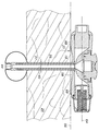
우선, 도면 중 도 1 및 2를 참조하면, 베이스(12), 튜브(14), 인플레터블 벌룬(16)을 구비하는 종래의 경장 공급 튜브 조립체(10)가 도시되어 있다. 도 2에 도시한 바와 같이, 조립체(10)는 피부 또는 위장벽(20) 등의 동물 또는 인간의 부위에 형성된 스토마(18)를 통해 연장된다. 베이스(12)의 하부(22)는 스토마(18) 상에 놓여 그 내에 부분적으로 놓이고, 튜브(14)는 체강의 의도된 부분 내로 연장되어 인플레터블 벌룬(16)에 의해 소정 위치에 보유된다. 튜브(14) 자체는 일반적으로 하나 이상의 유체 채널 또는 루멘을 갖는다. 제1 루멘(24)이 음식물, 액체 및 의약품 등의 유체 및 반고체 물질을 통과시키는데 이용되는 한편, 제2 루멘(26)은 벌룬(16)의 팽창을 허용하기 위해 통상적으로 공급된다. 조립체(10)를 배치한 사람 또는 동물이 움직이기 쉽기 때문에 그리고 음식물, 의약품 및 다른 액체, 가스 및 반고체 물질을 투여하도록 조립체(10)를 보호자가 이용하고 있을 때 조립체가 또 다른 움직임 및 로킹 작용을 받기 때문에, 조립체(10)는 조립체(10)를 경시적으로 약화시켜서 조립체 재료 내에 "응력 라이저"를 야기할 수 있는 응력을 받는데, 상기 응력 라이저는 누설을 초래하여 벌룬(16)을 디플레이트하게 하거나 또는 체강의 의도되지 않은 영역 내로 다른 전달된 물질을 누설하게 할 수 있는 크랙 및 구멍이다. 이러한 문제점을 최소화하는 시도에서, 베이스(12)의 하부(22)는 종종 조립체의 구조에 추가된 신뢰도를 제공하도록 트랜지션 넥 도는 스트레인 릴리프 넥으로 불리는 형태의 볼스터링 재료(28)로 구성된다. 이는 실리콘 등의 물질이 베이스(12) 및/또는 튜브(14)를 형성하는데 이용될 때 특히 필요하다는 것을 알았다. 이와 같이 추가된 재료(28)는 종종 스토마(18)를 바로 둘러싸는 조직과 접촉하고, 일부 경우에, 도 2에서 알 수 있는 바와 같이 스토마(18) 내의 하측으로 돌출한다. 이러한 경우에, 이와 같이 추가된 재료(28)는 스토마를 둘러싸는 조직을 자극하여 염증을 일으킴으로써, 환자에게 추가적인 불편함 및 문제를 야기할 수 있다.
Referring first to Figures 1 and 2 of the drawings, there is shown a conventional long
따라서, 스토마 자극 및 트라우마에 대한 잠재성을 감소시키는데 도움을 주는 개선된 경장 공급 장치 설계에 대한 필요성이 있다.
Therefore, there is a need for an improved stem supply design that helps to reduce the potential for stoma stimulation and trauma.
본원에서 논의되는 어려움 및 문제점을 감안하여, 본 발명은 인체 외부로 전개되는 베이스와, 스토마를 통해 삽입에 의해 인체의 루멘 내로 전개되는 튜브를 구비하는 경장 공급 장치를 제공한다. 상기 튜브는 근위 단부, 말단부, 외경부 및 상기 근위 단부와 상기 말단부 사이의 길이부를 갖고, 상기 튜브는 상기 튜브의 상기 길이부에 대체로 평행한 종축을 형성한다. 상기 베이스는 상부면, 대체로 대향된 하부면, 제1 단부 및 제2 단부 그리고 서로에 대체로 대향되며 상기 상부면과 하부면 및 상기 제1 단부와 상기 제2 단부를 연결하는 제1 측부와 제2 측부를 갖는다. 상기 튜브의 상기 근위 단부는 상기 베이스의 상기 하부면으로부터 멀어지게 매달리도록 연결된다. 상기 베이스의 상기 하부면은 리세스를 갖고, 상기 하부면에 대체로 평행하며 상기 튜브의 상기 종축에 대체로 수직인 평면을 형성하는 상기 베이스의 제1 및 제2 단부들 근방에 2개의 대향하는 패드를 갖는다. 상기 리세스는 상기 패드들 사이에 있고, 상기 베이스의 상부면을 향하는 방향으로 상기 하부면과의 연결 지점으로부터 상측방향으로 연장되는 제1 및 제2 측부 내로의 대체로 오목하지만 매끄러운 전이부이다. 상기 리세스는 상기 튜브의 근위 단부를 둘러싸고, 상기 베이스의 하부면과 상기 평면 사이의 공기 공간을 형성하도록 상기 튜브 또는 상기 베이스를 형성하는 재료가 전혀 없다.
In view of the difficulties and problems discussed herein, the present invention provides a tampon feeding device comprising a base deployed out of the body and a tube deployed into the lumen of the body by insertion through the stoma. The tube has a proximal end, a distal end, an outer diameter, and a length between the proximal end and the distal end, the tube forming a longitudinal axis substantially parallel to the length of the tube. The base includes an upper surface, a generally opposed lower surface, a first end and a second end, and generally opposite to each other and having a first side connecting the upper and lower surfaces and the first end and the second end, Side. The proximal end of the tube is connected so as to hang away from the lower surface of the base. The lower surface of the base having recesses and having two opposing pads in the vicinity of the first and second ends of the base forming a plane generally parallel to the lower surface and generally perpendicular to the longitudinal axis of the tube . The recess is a generally concave but smooth transition between the pads and into the first and second sides extending upwardly from a point of connection with the bottom surface in a direction toward the top surface of the base. The recess surrounds the proximal end of the tube and has no material forming the tube or base to form an air space between the bottom surface of the base and the plane.
소망한다면, 상기 하부면은 상기 하부면과 상기 평면 사이에 하나 이상의 통로를 형성하여, 상기 베이스의 상기 리세스 내외부로 주위 공기가 자유롭게 순환하게 할 수 있다. 또한, 상기 베이스의 하부면이 사용시에 스토마를 형성하는 조직과의 접촉을 감소시킬 수 있기에 충분한 사이즈를 갖는 것이 바람직하다. 추가로, 상기 리세스 및/또는 통로는 상기 베이스의 하부면의 세척 및 처리를 위해 그리고 조직에 대면하기 위해 적절하게 크기설정된 스웹(swabs), 예컨대 면봉이 방해받지 않게 삽입하게 한다. 또 달리 바람직한 특징은 스토마를 둘러싸는 조직에 또 다른 자극을 야기할 수 있는 날카로운 에지가 상기 장치의 베이스에 없거나 또는 제한된다는 점이다.
If desired, the lower surface may form one or more passages between the lower surface and the plane so that ambient air can freely circulate to the interior and exterior of the recess of the base. It is also preferred that the lower surface of the base has a size sufficient to reduce contact with the tissue forming the stoma during use. In addition, the recesses and / or passageways allow appropriately sized swabs, such as swabs, to be inserted unobstructed for cleaning and treatment of the lower surface of the base and for facing tissue. Yet another preferred feature is that the sharp edges that may cause another stimulus in the tissue surrounding the stoma are absent or limited at the base of the device.
경장 공급 장치의 베이스는 장축(major axis)과 단축(minor axis)을 형성하며, 상기 장축은 상기 제1 및 제2 단부들을 통해 연장되고, 상기 단축은 상기 장축에 직교하며 상기 제1 및 제2 측부들을 통해 연장된다. 상기 하부면 내의 리세스는 상기 단축을 따라 대체로 오목하고, 상기 단축을 따라 볼록하도록 대체로 평탄하다. 상기 베이스의 제1 및 제2 측부들은 상기 장축에 평행한 방향에서 볼 때 상기 하부면에 인접한 영역 내에서 적어도 상측으로 만곡됨으로써, 상기 단부들로부터 멀어지는 상기 측부들이 상기 패드와 관련되지 않도록 상기 리세스를 형성할 수 있다. 상기 하부면의 상기 패드는 상기 평면과 접촉하며, 스토마를 둘러싸는 조직에 대해 안착하고, 베이스를 지지하며, 공기 순환을 허용하도록 설계된다.
Wherein the base of the elongate feeder forms a major axis and a minor axis, the major axis extending through the first and second ends, the minor axis being orthogonal to the long axis, and the first and second Lt; / RTI > The recess in the lower surface is generally concave along the minor axis and is generally flat to be convex along the minor axis. The first and second sides of the base being curved at least upwardly in an area adjacent to the lower surface when viewed in a direction parallel to the longitudinal axis such that the sides away from the ends are not associated with the pad, Can be formed. The pads on the bottom surface are in contact with the plane, are seated against tissue surrounding the stoma, support the base, and are designed to allow air circulation.
상기 장치의 튜브는 상기 튜브의 근위 단부 주위에 트랜지션 넥이 없거나 최소한으로 한 상태에서 그리고 상기 베이스의 패드 위로 연장되는 볼스터링 재료 또는 트랜지션 넥이 없는 상태에서 상기 베이스의 하부면으로부터 멀어지게 매달린다. 상기 근위 단부의 영역에서의 상기 튜브의 외경부가 균일한 직경을 가지거나, 또는 변형적으로, 상기 튜브의 길이부의 주요부에 대해 균일한 직경을 갖는 것이 바람직하다. 또 다른 실시예에서, 상기 튜브의 균일한 직경은 상기 근위 단부로부터 상기 말단부 쪽으로 상기 튜브의 길이부를 따라 적어도 10 mm의 거리만큼 연장해야 한다. 바람직하게, 상기 튜브의 길이부의 주요부에 대한 균일한 직경은 상기 패드에 의해 형성된 상기 평면 위로 그리고 상기 리세스 내로 연속한다.
The tube of the device is suspended away from the lower surface of the base in the absence of a transition neck around the proximal end of the tube, or at a minimum, and without a ball stuffing material or transition neck extending over the pad of the base. It is preferred that the outer diameter portion of the tube in the region of the proximal end has a uniform diameter or alternatively has a uniform diameter relative to the major portion of the length of the tube. In yet another embodiment, the uniform diameter of the tube should extend at least 10 mm along the length of the tube from the proximal end toward the distal end. Preferably, a uniform diameter for the main portion of the length of the tube is continued above the plane defined by the pad and into the recess.
상기 리세스를 형성하고, 상기 튜브의 근위 단부와 상기 베이스의 하부면 사에 트랜지션 넥을 최소한 내지는 형성하지 않고, 상기 패드를 형성하는 능력을 촉진시키는 하나의 방법은, 폴리우레탄 성분의 하부면 및 튜브를 적어도 부분적으로 형성하는 것이다.
One method of forming the recesses and facilitating the ability to form the pads without forming at least a transition neck on the proximal end of the tube and the lower surface of the base is to provide a lower surface of the polyurethane component At least partially forming the tube.
경장 공급 장치 및 그 개선된 베이스에 대한 상기한 특징 및 다른 특징들 그리고 그 이점에 대한 이해는, 특히 첨부된 도면과 함께 이루어진다면 하기의 상세한 설명으로부터 얻어질 수 있다.
An understanding of the above and other features and advantages of the present invention and the improved base thereof can be obtained from the following detailed description, particularly when taken in conjunction with the accompanying drawings.
정의Justice
본원에 사용된 바와 같은 하기의 용어는 그 문맥이 다른 의미를 요구하거나 다른 의미가 나타내어지지 않는다면 특정한 의미를 가지며; 또한 단수는 복수를 대체로 포함하고, 복수는 달리 지칭되지 않는다면 단수를 대체로 포함한다.
The following terms as used herein have the specific meaning unless the context requires otherwise or where different meanings are indicated; Also, the singular includes substantially plural, and plural includes substantially singular unless otherwise indicated.
본원에 사용된 바와 같이, 용어 "포함하다", "포함하는" 및 그로부터의 다른 유도체는 임의의 언급된 특징, 요소, 정수, 단계 또는 구성요소의 존재를 특정하는 개방된 용어가 되도록 의도되지만, 하나 이상의 다른 특징, 요소, 정수, 단계, 구성요소 또는 그 그룹에 대한 존재 또는 추가를 배제하지 않는다. 마찬가지로, 용어 "구비하다", "구비하는"뿐만 아니라, 용어 "갖다", "갖는" 및 그 유도체는 용어 "포함하다"와 같이 해석되도록 의도되며, 임의의 언급된 특징, 요소, 정수, 단계 또는 구성요소의 존재를 특정하는 개방된 용어가 되도록 의도되지만, 하나 이상의 다른 특징, 요소, 정수, 단계, 구성요소 또는 그 그룹에 대한 존재 또는 추가를 배제하지 않는다.
As used herein, the terms "comprises,""comprising," and other derivatives therefrom are intended to be open terms that specify the presence of any stated feature, element, element, step or component, Does not exclude the presence or addition of one or more other features, elements, integers, steps, components, or groups thereof. Similarly, the terms " comprise, "" having ", and derivatives thereof are intended to be interpreted as including the term " comprises ", as well as the terms & Or the like, but do not preclude the presence or addition of one or more other features, elements, integers, steps, components, or groups thereof.
본원에 사용된 바와 같이, 용어 "실질적인" 또는 "실질적으로"는 큰 크기 또는 정도; 상당한 또는 큰 양으로 행하는 것을 지칭하며, 예컨대, 본원에 사용된 바와 같은 "실질적으로"는 적어도 70%를 포함하는 것을 의미한다.
As used herein, the term "substantial" or "substantially" refers to a large size or extent; Quot; substantially "as used herein refers to including at least 70%.
본원에 사용된 바와 같이, 기재된 수와 관련된 용어 "약"은 기재된 수의 ±10%의 양을 지칭한다.
As used herein, the term "about" in connection with a number mentioned refers to an amount of +/- 10% of the number stated.
본원에 사용된 바와 같이, 외측 튜브 직경의 문맥에서의 용어 "균일한(uniform)"은 본 발명에 따른 경장 공급 장치의 베이스에 부착된 튜브의 최초 10 mm의 80%에 대한 20% 이상 변화하지 않는 직경을 지칭한다.
As used herein, the term "uniform" in the context of the outer tube diameter does not change by more than 20% relative to 80% of the first 10 mm of the tube attached to the base of the length feeder according to the invention Diameter.
이러한 용어들은 본 명세서의 나머지 부분에서 추가적인 용어로 정의될 수 있다.
These terms may be defined in additional terms in the remainder of this specification.
도 1은 예시적인 종래의 장치에 대한 사시도,
도 2는 도 1에 도시한 종래의 장치에 대한 측단면도,
도 3은 베이스의 하부면을 도시한 본 발명에 따른 경장 공급 장치에 대한 사시도,
도 4는 본 발명에 따른 경장 공급 장치에 대한 평면도,
도 5는 도 4의 5-5선을 따라 취한 본 발명에 따른 경장 공급 장치에 대한 단부도,
도 6은 도 4의 6-6선을 따라 취한 본 발명에 따른 경장 공급 장치에 대한 단면도,
도 7은 도 4의 7-7선을 따라 취한 본 발명에 따른 경장 공급 장치에 대한 단면도,
도 8은 도 4의 8-8선을 따라 취한 본 발명에 따른 경장 공급 장치에 대한 단면도.Figure 1 is a perspective view of an exemplary prior art device,
Fig. 2 is a side sectional view of the conventional apparatus shown in Fig. 1,
3 is a perspective view of a long feeding device according to the present invention showing a lower surface of a base,
Figure 4 is a plan view of a long feeding device according to the present invention,
Fig. 5 is an end view of a long feeding device according to the present invention taken along line 5-5 of Fig. 4; Fig.
FIG. 6 is a cross-sectional view of the long feeding device according to the present invention taken along line 6-6 of FIG. 4;
7 is a cross-sectional view of a long feeder according to the present invention taken along line 7-7 of FIG. 4;
FIG. 8 is a cross-sectional view of a long feeder according to the present invention taken along
일반적으로, 본원에 개시된 발명(들)은 경장 공급을 필요로 하는 환자를 위한 개선된 의료 케어에 관한 것이다. 보다 상세하게, 본원에 개시된 발명(들)은 인체 외부로 전개되는 개선된 베이스, 인체 외부로부터 인체 내부로 물질 전달을 위한 튜브, 및 선택적으로 스토마를 통해 삽입에 의해 인체의 루멘 내로 전개되는 유치용 리테이너(indwelling retainer)를 갖는 경장 공급 장치에 관한 것이다. 상기 장치는 스토마를 바로 둘러싸는 조직의 자극을 감소시키도록 의도된 베이스 및 튜브 설계를 갖는다.
In general, the invention (s) disclosed herein is directed to improved medical care for patients in need of a rectal supply. More specifically, the invention (s) disclosed herein provides an improved base for deployment outside the human body, a tube for delivering material from the outside of the human body into the human body, and optionally a stent for deployment into the lumen of the human body, To an elongate feeding device having an indwelling retainer. The device has a base and tube design that is intended to reduce the irritation of the tissue immediately surrounding the stoma.
본 발명의 일 실시예에서, 경장 공급 장치는 기능적 베이스를 제한된 양의 공간 내에 제공하도록 상부로부터 볼 때 역전된 모래시계 형상을 이용한다. 베이스의 설계는 베이스의 하부 상에 형성된 2개의 "패드"를 내장한다. 이러한 비외상성 "패드"는 인체에 대해 안착하며, 스토마로부터 이격된 위치에 인체에 대한 압력을 분산시킨다. 그 결과, 본 발명의 개선된 베이스는 스토마 자극 및 트라우마를 감소시키는 추가된 특징을 갖는 종래의 장치에 대한 모든 기능을 제공한다. 튜브의 근위 단부를 바로 둘러싸는 장치 근방에서, 베이스 설계는 스토마 형성 및 스토마 건강을 개선하도록 스토마 사이트에 공기 순환을 허용하는 한편, 스토마 사이트의 보다 쉬운 세척을 허용한다. 또한, 이러한 설계는 인체에 대해 매우 스무스하고, 어떠한 날카로운 에지를 가지지 않는다. 더욱이, 개선된 베이스 설계 및 인체공학은 연장 세트에 부착하는 한편, 베이스를 쉽게 파지하게 한다. 이러한 종래의 경장 공급 장치가 작동하는 방법에 대한 일반적인 설명은, 예컨대 Foster 등에 허여된 미국특허 5,995,546호를 참조하며, 그 내용은 전체적으로 참조로 편입된다.
In one embodiment of the present invention, the continuous feeder utilizes an inverted hourglass shape when viewed from above to provide a functional base within a limited amount of space. The design of the base incorporates two "pads" formed on the bottom of the base. This non-traumatic "pad " seats against the body and distributes the pressure to the body at a spaced distance from the stoma. As a result, the improved bass of the present invention provides all the functionality for conventional devices with added features that reduce stoma stimulation and trauma. In the vicinity of the device immediately surrounding the proximal end of the tube, the base design permits air circulation to the stomase site to improve stoma formation and health, while allowing easier washing of the stomase. This design is also very smooth for the human body and has no sharp edges. Moreover, the improved base design and ergonomics allow the base to be easily gripped while attaching to the extension set. A general description of how such conventional yarn feeding devices work is described, for example, in U.S. Patent 5,995,546 issued to Foster et al., The contents of which are incorporated by reference in their entirety.
본 발명의 하나 이상의 실시예에 대해 상세하게 참조가 이루어지며, 그 예는 도면에 도시된다. 각각의 예 및 실시예는 본 발명의 설명에 의해 제공되며, 본 발명을 제한하는 것으로 의도되지 않는다. 예를 들면, 하나의 실시예에 대한 일부로서 도시 또는 기술된 특징은 또 다른 실시예를 형성하도록 다른 실시예와 함께 이용될 수 있다. 본 발명은 본 발명의 범위 및 사상으로부터 다른 수정 및 변경이 포함되는 것으로 의도된다.
Reference will now be made in detail to one or more embodiments of the invention, examples of which are illustrated in the drawings. Each example and embodiment is provided by way of explanation of the invention and is not intended to limit the invention. For example, features shown or described as part of one embodiment may be utilized with other embodiments to form another embodiment. It is intended that the present invention include other modifications and variations from the scope and spirit of the invention.
도면 중 도 3 내지 8을 참조하면, 인체 외부로 전개되는 베이스(32)와, 스토마(18)를 통해 삽입에 의해 인체 내로 경피식으로 전개되는 튜브(34)를 갖는 개선된 경장 공급 장치(30)가 도시되어 있다. 바람직하게, 상기 장치는 인체 외부로부터 전개된다. 선택적으로, 상기 장치(30)는 장치(30)를 소정 위치에 보유하며 튜브(34)가 그 의도된 위치로부터 의도치 않게 제거되는 것을 어렵게 하기 위한 인플레이션 벌룬을 구비할 수 있다. 또한, 상기 장치는 종래의 경장 공급 튜브 장치를 갖는 인플레이션 루멘(37) 및 공급/전달 루멘(39)을 가질 것이며, 그 설계 및 용도는 잘 공지되어 있다.
3 to 8 of the drawings, there is shown an improved long feeding device (not shown) having a base 32 deployed outwardly of the human body and a
튜브(34)는 근위 단부(36), 외경부(40)를 갖는 말단부(38), 및 근위 단부(36)와 말단부(38) 사이의 길이부(42)를 갖는다. 튜브(34)는, 튜브(34)의 길이부(42)에 대체로 평행한 종축(44)을 형성한다.
The
베이스(32)는, 베이스의 제1 단부(52)와 제2 단부(54)에 결합된 상부면(48) 및 대체로 대향된 하부면(50)을 갖는다. 또한, 베이스(32)는 서로 대체로 대향되며 상부면(48), 하부면(50), 제1 단부(52) 및 제2 단부(54)에 또한 결합되는 제1 측부(53)와 제2 측부(55)를 갖는다.
The
도면에 도시한 실시예에서, 베이스(32)는 평면도, 저면도, 측면도 및 단부도와 관련하여 직사각형 또는 타원형을 가짐으로써, 베이스(32)는 장축(64)과 단축(66)을 형성하며, 상기 장축은 제1 단부(52)와 제2 단부(54)를 통해 연장되고, 상기 단축(66)은 제1 측부(53)와 제2 측부(55)를 통해 연장된다. 도 4, 6 및 7 참조. 단축(66)에서 평행하게 볼 때, 베이스(32)는 하부면(50)에 인접한 대체로 오목한 형상을 가지며, 장축(64)에서 평행하게 볼 때 대체로 볼록한 형상을 갖는다. 그러나, 본원에서 의도된다면, 본 발명의 범위 내에서 다른 베이스 형상이 고려된다.
The
튜브(34)의 근위 단부(36)는 베이스(32)의 하부면(50)으로부터 멀어지게 매달리도록 연결된다. 베이스(32)의 하부면(50)은 하부면(50)에 대체로 평행하며 튜브(34)의 종축(44)에 대체로 수직인 평면(56)을 형성한다. 도 5, 6 및 7 참조. 이는 장치(30)가 사용자와 접촉하는 위치를 되풀이하도록 의도된 평면이다. 튜브(34)가 베이스(32)로부터 중앙에 매달린 것으로 도시되지만, 중앙을 벗어난 위치가 가능하다.
The
공기 순환을 허용하고, 스토마(18)를 둘러싸고 있는 외부면(21)에 또는 그 근방에서 조직(20)과 베이스(32)의 접촉을 최소화하기 위해, 베이스(32)의 하부면(50)은 하나 이상의 리세스(58)를 구비하거나 또는 형성하며, 이는 제1 단부(52)와 제2 단부(54) 사이에서 대체로 오목하고, 베이스(32)의 상부면(48)을 향하는 방향으로 평면(56)으로부터 상측으로 연장된다. 도 3 및 5-7 참조. 리세스(58)는 튜브(34)의 근위 단부(36)의 적어도 이루를 둘러싸고, 리세스(58)는 베이스(32) 또는 튜브(34)를 형성하는 재료가 없다. 그 결과, 리세스(58)는 베이스(32)의 하부면(50)과 평면(56) 사이에 공기 공간을 형성한다.
The
베이스(32)의 형상으로 인해, 베이스(32)의 하부면(50) 내에 하나 이상의 통로(62)가 형성됨으로써, 베이스(32)를 둘러싸는 주위 공기로부터 리세스(58) 내외로 공기가 순환하게 허용한다. 도면에서 알 수 있는 바와 같이, 이러한 통로(62)는 하부면(50)에 인접한 제1 측부(53)와 제2 측부(55)의 가벼운 커빙 업(curving up)에 의해 형성됨으로써, 만곡된 영역(63)은 장치(30)의 측부로부터 리세스(58) 내로 공기 흐름을 허용한다. 또한, 제1 및 제2 측부(53, 55)의 가벼운 커빙 업은 제1 단부(52)로부터 제2 단부(54)로 장축(64)을 따라 연장된다. 그 결과, 자극 및 불편함을 야기할 수 있는 스토마(18)를 둘러싸는 조직(21) 내로 돌출하는 날카로운 에지가 없다.
Due to the shape of the base 32 one or
통로(62)는 임의 개수의 형상을 취할 수 있으며, 이러한 형상은 본 발명의 범위 내에 있도록 의도된다. 예를 들면, 튜브(34)의 근위 단부(36) 주위의 임의 지점에서 베이스(32) 내로 보다 깊은 그루브(미도시)가 형성될 수 있다. 리세스(58)의 사이즈 및 용적은 주위 공기가 베이스(32) 둘레에서 자유롭게 순환할 수 있도록 그리고 베이스(32)의 하부면(50)이 스토마(18)를 둘러싸는 조직과의 접촉을 회피 또는 적어도 감소시킬 수 있도록 해야 한다. 추가로, 통로(62)는 리세스(58) 및 스토마 조직 표면 내에서 세척을 위해 접근을 허용한다. 이와 관련하여, 리세스(58)는 면봉 또는 다른 적절한 세척 장치가 세척 및 다른 작업을 위해 리세스(58) 내로 삽입될 수 있기에 충분한 사이즈를 가지는 것이 바람직하다.
The
도면에 도시한 실시예에서, 베이스(32)는 대체로 직사각형 또는 타원형 형상을 가지고, 따라서 베이스(32)는 장축(64)과 단축(66)을 형성하며, 상기 장축은 제1 단부(52)와 제2 단부(54)를 통해 연장되고, 상기 단축은 제1 측부(53)와 제2 측부(55)를 통해 연장된다. 도 4, 6 및 7 참조. 베이스(32)의 하부면(50) 내의 리세스(58)는 튜브(34)의 근위 단부(36)에 바로 인접한 하부면(50)이 약간 딥핑될 수 있더라도, 단축(66)을 따라 그리고 그에 평행하게 베이스(32)를 볼 때, 도 7에서 알 수 있는 바와 같이 장축(64)을 따라 대체로 오목하다. 도 6 및 7에 도시한 바와 같이, 튜브(34)의 근위 단부(36)에 바로 인접한 하부면(50)의 임의의 약간의 딥핑은 항상 리세스 내, 즉 평면(56) 상에 있다. 도 8에 나타낸 바와 같이, 튜브(34)의 길이부(42)는 근위 단부(36) 쪽으로 균일한 외경부를 가지며, 이러한 균일한 직경부는 리세스(58) 내로 연장된다. 또한, 대체로 오목한 구성은 전체 형상이 오목한 구성을 갖는다면 각종 다른 표면 윤곽 및 불규칙성을 포함할 수 있다. 이에 따라, 용어 "오목한"은 베이스(32)의 하부면(50) 내의 리세스(58)를 형성하는 임의의 형상을 포함하도록 의도된다.
The
장축(64)을 따라 그리고 그에 평행하게 베이스(32)를 볼 때, 도 5 및 6에서 알 수 있는 바와 같이, 리세스(58)는 튜브(34)의 근위 단부(36)를 바로 둘러싸는 영역 내에 오목한 특징부를 포함하지만, 그 측부는 베이스(32)의 만곡된 영역(63)에 의해 도시된 바와 같이 제1 측부(53)와 제2 측부(55)에 인접하게 볼록 형상이 될 수 있다. 이에 따라, 하부면(50) 내의 리세스(58)는 (단축(66)을 따라 볼 때) 장축(64)을 따라 대체로 오목할 수 있다.
As seen in Figures 5 and 6, when the
리세스(58)를 형성하는 베이스(32) 내의 곡률로 인해, 평면(56)과 접촉하는 제1 단부(52)와 제2 단부(54)에 인접하게 한 쌍의 패드(68)가 형성되며, 이는 베이스(32)의 나머지 부분을 지지하고 상승시키고, 공기 순환을 허용하며, 패드(68)에 의해 폐색되지 않는 표면 조직을 세척하기 위한 쉬운 접근을 제공하도록 스토마(18)를 둘러싸는 조직에 대해 안착하도록 설계된다. 여기서, 패드(68)는 임의 개수의 형상을 취할 수 있고, 이러한 형상은 본 발명의 범위 내에 있는 것으로 의도된다. 또한, 베이스(32) 내의 패드(68)는 튜브(34)의 근위 단부(36) 둘레의 임의 위치에 그리고 임의 개수로 위치될 수 있다. 도 7에 도시한 바와 같이, 패드의 하부면은 만곡되지만, 패드를 위한 다른 하부면이 예컨대 평탄형, 부분적으로 오목형, 물결형 및 그 조합으로 가능할 수 있다.
Due to the curvature in the base 32 forming the recess 58 a pair of
스토마(18)를 둘러싸는 조직에 대한 보다 많은 공기 순환 및 보다 적은 자극을 허용하도록 베이스(32)를 의도하게 설계할 때, 튜브(34)의 형성을 위한 종래의 물질, 예컨대 실리콘을 다른 물질로 전환하는 것이 유리하다는 것을 알았다. 특히, 폴리우레탄, 또는 튜브(34) 및 선택적으로, 베이스(32)를 위한 폴리우레탄을 포함하는 물질을 이용하면, 튜브(34)의 주요부 또는 전체 길이부(42)가 튜브(34)의 근위 단부(36)에 가능한 한 근접하게 균일한 외경부(40)를 갖게 하는 한편, 종래의 공급 튜브 조립체 설계에서 갖는 문제점으로 전술된 "응력 라이저"의 빈번함 및 심각성을 감소시킨다.
When the
경장 공급 장치(30)의 끼워맞춤 및 기능을 성취하는 입증된 방법은 경장 공급 튜브에 종래에 사용된 실리콘 튜빙(silicon tubing)보다 덜 경질이고, 덜 거칠며 그리고/또는 덜 고무같은 물질의 튜브(34)를 형성하는 것이다. 일례로서, 튜브(34)는 약 65A 내지 약 80A의 쇼어 경도와, 약 2500 내지 약 6000 psi의 극한 인장강도를 갖는 물질로 형성될 수 있다. 이러한 물질이 약 100%의 신장에서 300 psi의 인장력을 갖고 그리고/또는 (종래의 일부 실리콘 탄성중합체 물질과 유사할 수 있는) 약 200% 신장에서 500 psi의 인장력을 가질 수 있지만, 보다 큰 경도 및 극한 인장강도는 튜브(34)를 스트레치에 보다 저항력 있게 하는 한편, 여전히 가요성을 보유하는 것으로 고려된다. 예시적인 물질에는, Wilminton, Massachusetts, ThermedicsTM Polymer Products의 Lubrizol Advanced Materials로부터 입수가능한 TECOFLEX® 의료 등급의 지방족 폴리에테르 폴리우레탄 등의 열가소성 폴리우레탄이 있다. 예를 들면, TECOFLEX® EG-80A는 작업 특성이 특히 좋은 것으로 알려져 있다. 하기의 표 1은 TECOFLEX® EG-80A에 대한 몇 가지의 대표적인 특징을 제공한다.
A proven method of accomplishing the fit and function of the
상술한 바와 같이, 튜브(34)의 재료는 약 65A 내지 약 80A의 쇼어 경도를 바람직하게 가질 수 있다. 플라스틱에 대한 쇼어 경도 시험은 쇼어 A 또는 쇼어 D 스케일을 이용하여 쇼어(경도계)에 의해 가장 통상적으로 측정된다. 쇼어 A 스케일은 "보다 연질"의 고무에 사용되는 한편, 쇼어 D 스케일은 "보다 경질"의 고무에 사용된다. 쇼어 A 경도는 고무 또는 연질의 플라스틱 등의 탄성 재료의 상대 경도가 쇼어 A 경도계로 불리는 도구에 의해 결정될 수 있다. 인던터(indenter)가 샘플을 완전히 관통하면, 0의 판독이 얻어지고, 관통이 발생하지 않으면, 100이 판독된다. 그 판독은 크기가 없다.
As described above, the material of the
쇼어 경도는 경도계로 알려진 장치에 의해 측정되며, 때때로 경도계 경도로서 지칭된다. 경도값은 샘플 내에 경도계 인덴터 풋(Durometer indenter foot)의 관통에 의해 결정된다. 고무 및 플라스틱의 탄성으로 인해, 경도 판독은 경시적으로 변화할 수 있고, 그에 따라 인덴테이션 시간은 경도 번호와 함께 때때로 보고된다. ASTM 시험 번호는 ASTM D2240인 한편, 유사한 ISO 시험법은 ISO 868이다.
Shore hardness is measured by a device known as a hardness meter and is sometimes referred to as hardness meter hardness. The hardness value is determined by the penetration of a durometer indenter foot in the sample. Due to the elasticity of the rubber and plastic, the hardness readings can change over time, and hence the indentation times are sometimes reported with hardness numbers. ASTM test number is ASTM D2240 while a similar ISO test method is ISO 868.
이에 따라, 본 발명의 예시적인 실시예가 본원에 제공되지만, 본 발명은 당업자에게 명백한 바와 같이 각종 변형 형태로 실시될 수 있다. 본 발명의 이해를 돕고 청구범위의 근거를 제공하기 위해, 각종 도면이 본 설명에 포함된다. 도면은 축척되지 않으며, 관련 요소는 본 발명의 신규한 특징을 강조하기 위해 생략될 수 있다. 도면에 도시한 구조적 및 기능적 세부 사항은 당업자에게 본 발명의 실시를 교시할 목적으로 제공되며, 고려되는 제한사항을 의도한 것이 아니다. 좌측, 우측, 전방 또는 후방 등의 방향 용어는 본 발명의 이해를 돕도록 제공되며, 고려되는 제한사항을 의도한 것이 아니다.
Accordingly, while exemplary embodiments of the present invention are provided herein, the present invention can be embodied in various forms as will be apparent to those skilled in the art. Various figures are included in the description to facilitate understanding of the present invention and to provide a basis for the claims. The drawings are not to scale and the relevant elements may be omitted to emphasize the novel features of the present invention. The structural and functional details shown in the drawings are provided to teach those skilled in the art the teachings of the present invention and are not intended to be limiting. Directional terms such as left, right, forward, or rearward are provided to aid understanding of the present invention and are not intended to be limiting.
본 발명의 특정 실시예가 본원에 기술되었지만, 첨부한 특허청구범위의 범위로부터 벗어나지 않고서 기술된 실시예에 변경 및 수정이 이루어질 수 있음이 당업자에게 명백할 것이다.
Although specific embodiments of the invention have been described herein, it will be apparent to those skilled in the art that changes and modifications may be made to the embodiments described without departing from the scope of the appended claims.
Claims (14)
상기 튜브는 근위 단부, 말단부, 외경부 및 상기 근위 단부와 상기 말단부 사이의 길이부를 갖고, 상기 튜브는 상기 튜브의 상기 길이부에 대체로 평행한 종축을 형성하고;
상기 베이스는 상부면, 대체로 대향된 하부면, 제1 단부 및 제2 단부 그리고 서로에 대체로 대향되며 상기 상부면과 하부면 및 상기 제1 단부와 상기 제2 단부를 연결하는 제1 측부와 제2 측부를 갖고;
상기 튜브의 상기 근위 단부는 상기 베이스의 상기 하부면으로부터 멀어지게 매달리도록 연결되고;
상기 베이스의 상기 하부면은 상기 하부면에 대체로 평행하며 상기 튜브의 상기 종축에 대체로 수직인 평면을 형성하고;
상기 하부면은 상기 베이스의 상기 상부면을 향하는 방향으로 상기 평면으로부터 상측으로 연장되는 하나 이상의 리세스를 형성하고, 상기 리세스는 상기 튜브의 상기 근위 단부의 적어도 일부를 직접 둘러싸며 상기 베이스의 상기 하부면과 상기 평면 사이의 공기 공간을 형성하고;
상기 베이스는 장축과 단축을 형성하며, 상기 장축은 상기 제1 및 제2 단부들을 통해 연장되고, 상기 단축은 상기 제1 및 제2 측부들을 통해 연장되며; 그리고
상기 하부면 내의 상기 리세스는 상기 단축을 따라 볼 때 대체로 오목하고, 상기 베이스의 상기 제1 및 제2 측부들은 상기 장축에 평행한 방향에서 볼 때 상기 하부면에 인접한 영역 내에서 적어도 상측으로 만곡되는,
경장 공급 장치.
1. An enteral feeding device comprising a base deployed to the outside of a human body and a tube inserted through the stoma from the outside of the human body,
The tube having a proximal end, a distal end, an outer diameter, and a length between the proximal end and the distal end, the tube defining a longitudinal axis generally parallel to the length of the tube;
The base includes an upper surface, a generally opposed lower surface, a first end and a second end, and generally opposite to each other and having a first side connecting the upper and lower surfaces and the first end and the second end, Side;
The proximal end of the tube being connected to be suspended away from the lower surface of the base;
Said lower surface of said base forming a plane generally parallel to said lower surface and generally perpendicular to said longitudinal axis of said tube;
The bottom surface defining at least one recess extending upwardly from the plane in a direction toward the top surface of the base, the recess directly surrounding at least a portion of the proximal end of the tube, Forming an air space between the lower surface and the plane;
The base forming a major axis and a minor axis, the major axis extending through the first and second ends, the minor axis extending through the first and second sides; And
Wherein the recesses in the bottom surface are generally concave when viewed along the minor axis and the first and second sides of the base are curved at least upwardly in an area adjacent to the bottom surface as viewed in a direction parallel to the long axis felled,
A long supply.
상기 하부면은 상기 하부면과 상기 평면 사이에 하나 이상의 통로를 형성하여, 상기 베이스를 둘러싸는 주위 공기로부터 상기 베이스의 상기 리세스 내외부로 공기가 순환하게 하는,
경장 공급 장치.
The method according to claim 1,
Wherein the lower surface forms one or more passages between the lower surface and the plane to cause air to circulate from ambient air surrounding the base to the interior and exterior of the recess,
A long supply.
상기 리세스는, 사용 시에, 면봉을 수용하기에 충분한 사이즈를 갖는,
경장 공급 장치.
3. The method of claim 2,
Said recess being of a size sufficient to accommodate the swab in use,
A long supply.
상기 베이스의 상기 하부면은 상기 평면과 접촉하며, 상기 베이스를 지지하고 공기 순환을 허용하도록 상기 스토마를 둘러싸는 조직에 대해 받치도록 설계된 한 쌍의 패드를 형성하는,
경장 공급 장치.
The method according to claim 1,
The lower surface of the base being in contact with the plane and defining a pair of pads designed to support against the tissue surrounding the stoma to support the base and allow air circulation,
A long supply.
상기 베이스의 상기 하부면은 상기 평면과 접촉하며, 상기 베이스를 지지하고 공기 순환을 허용하도록 상기 스토마를 둘러싸는 조직에 대해 받치도록 설계된 한 쌍의 패드를 형성하는,
경장 공급 장치.
3. The method of claim 2,
The lower surface of the base being in contact with the plane and defining a pair of pads designed to support against the tissue surrounding the stoma to support the base and allow air circulation,
A long supply.
상기 튜브는 적어도 부분적으로 폴리우레탄으로 형성되는,
경장 공급 장치.
The method according to claim 1,
Wherein the tube is at least partially formed of polyurethane,
A long supply.
상기 근위 단부의 영역에서의 상기 튜브의 상기 외경부는 균일한 직경을 갖는,
경장 공급 장치.
The method according to claim 1,
Wherein the outer diameter portion of the tube in the region of the proximal end has a uniform diameter,
A long supply.
상기 튜브의 상기 균일한 직경은 상기 튜브의 상기 길이부의 주요부 위로 연장되는,
경장 공급 장치.
8. The method of claim 7,
The uniform diameter of the tube extending over a major portion of the length of the tube,
A long supply.
상기 튜브의 상기 균일한 직경은 상기 근위 단부로부터 상기 말단부 쪽으로 상기 튜브의 상기 길이부를 따라 적어도 10 mm의 거리만큼 연장되는,
경장 공급 장치.
8. The method of claim 7,
The uniform diameter of the tube extending from the proximal end toward the distal end by a distance of at least 10 mm along the length of the tube,
A long supply.
상기 장치는 적어도 부분적으로 폴리우레탄으로 구성되는,
경장 공급 장치.
The method according to claim 1,
The device comprises at least partly a polyurethane,
A long supply.
상기 튜브는 근위 단부, 말단부, 외경부 및 상기 근위 단부와 상기 말단부 사이의 길이부를 갖고, 상기 튜브는 상기 튜브의 상기 길이부에 대체로 평행한 종축을 형성하고;
상기 베이스는 상부면, 대체로 대향된 하부면, 제1 단부 및 제2 단부 그리고 서로에 대체로 대향되며 상기 베이스의 상기 상부면과 하부면 및 상기 제1 단부와 상기 제2 단부를 연결하는 제1 측부와 제2 측부를 갖고;
상기 튜브의 상기 근위 단부는 상기 베이스의 상기 하부면으로부터 멀어지게 매달리도록 연결되고;
상기 베이스의 상기 하부면은 상기 하부면에 대체로 평행하며 상기 튜브의 상기 종축에 대체로 수직인 평면을 형성하고;
상기 하부면은 상기 베이스의 상기 상부면을 향하는 방향으로 상기 평면으로부터 상측으로 연장되는 하나 이상의 리세스를 형성하고, 상기 리세스는 상기 튜브의 상기 근위 단부의 적어도 일부를 직접 둘러싸며 상기 베이스의 상기 하부면과 상기 평면 사이의 공기 공간을 형성하고;
상기 하부면은 상기 베이스를 둘러싸는 주위 공기로부터 상기 베이스의 상기 리세스 내외부로 공기가 순환하게 하는 하나 이상의 통로를 형성하고;
상기 베이스의 상기 제1 및 제2 측부들은 장축에 평행한 방향에서 볼 때 상기 하부면에 인접한 영역 내에서 적어도 상측으로 만곡되고;
상기 베이스의 상기 하부면은 상기 평면 접촉하며, 상기 베이스를 지지하고 공기 순환을 허용하도록 상기 스토마를 둘러싸는 조직에 대해 받치도록 설계된 한 쌍의 패드를 형성하고;
상기 튜브는 적어도 부분적으로 폴리우레탄으로 구성되며; 그리고
상기 근위 단부의 영역에서의 상기 튜브의 상기 외경부는 균일한 직경을 갖는,
경장 공급 장치.
1. A tongue feeding device comprising a base deployed to the outside of a human body and a tube deployed from the outside of the human body through insertion through the stoma,
The tube having a proximal end, a distal end, an outer diameter, and a length between the proximal end and the distal end, the tube defining a longitudinal axis generally parallel to the length of the tube;
The base includes an upper surface, a generally opposed lower surface, a first end and a second end, and generally opposite to each other, the upper and lower surfaces of the base, and a first side connecting the first end and the second end, And a second side;
The proximal end of the tube being connected to be suspended away from the lower surface of the base;
Said lower surface of said base forming a plane generally parallel to said lower surface and generally perpendicular to said longitudinal axis of said tube;
The bottom surface defining at least one recess extending upwardly from the plane in a direction toward the top surface of the base, the recess directly surrounding at least a portion of the proximal end of the tube, Forming an air space between the lower surface and the plane;
Said bottom surface defining at least one passage through which air circulates from ambient air surrounding said base to said interior and exterior of said recess in said base;
The first and second sides of the base being curved at least upwardly in a region adjacent to the lower surface as viewed in a direction parallel to the longitudinal axis;
The lower surface of the base is in planar contact and forms a pair of pads designed to support against the tissue surrounding the stoma to support the base and allow air circulation;
The tube being at least partially composed of polyurethane; And
Wherein the outer diameter portion of the tube in the region of the proximal end has a uniform diameter,
A long supply.
상기 장치는 적어도 부분적으로 폴리우레탄으로 구성되는,
경장 공급 장치.
12. The method of claim 11,
The device comprises at least partly a polyurethane,
A long supply.
상기 튜브는 근위 단부, 말단부, 외경부 및 상기 근위 단부와 상기 말단부 사이의 길이부를 갖고, 상기 튜브는 상기 튜브의 상기 길이부에 대체로 평행한 종축을 형성하고;
상기 베이스는 상부면, 대체로 대향된 하부면, 제1 단부 및 제2 단부 그리고 서로에 대체로 대향되며 상기 상부면과 하부면 및 상기 제1 단부와 상기 제2 단부를 연결하는 제1 측부와 제2 측부를 갖고;
상기 튜브의 상기 근위 단부는 상기 베이스의 상기 하부면으로부터 멀어지게 매달리도록 연결되고;
상기 베이스의 상기 하부면은 상기 하부면에 대체로 평행하며 상기 튜브의 상기 종축에 대체로 수직인 평면을 형성하고;
상기 하부면은 상기 베이스의 상기 상부면을 향하는 방향으로 상기 평면으로부터 상측으로 연장되는 하나 이상의 리세스를 형성하고, 상기 리세스는 상기 튜브의 상기 근위 단부의 적어도 일부를 직접 둘러싸며 상기 베이스의 상기 하부면과 상기 평면 사이의 공기 공간을 형성하며; 그리고
상기 베이스는 장축과 단축을 형성하며, 상기 장축은 상기 제1 및 제2 단부들을 통해 연장되고, 상기 단축은 상기 제1 및 제2 측부들을 통해 연장되고, 상기 하부면 내의 상기 리세스는 상기 장축을 따라 대체로 오목하고 상기 단축을 따라 볼록한,
경장 공급 장치.
1. A tongue feeding device comprising a base deployed to the outside of a human body and a tube deployed from the outside of the human body through insertion through the stoma,
The tube having a proximal end, a distal end, an outer diameter, and a length between the proximal end and the distal end, the tube defining a longitudinal axis generally parallel to the length of the tube;
The base includes an upper surface, a generally opposed lower surface, a first end and a second end, and generally opposite to each other and having a first side connecting the upper and lower surfaces and the first end and the second end, Side;
The proximal end of the tube being connected to be suspended away from the lower surface of the base;
Said lower surface of said base forming a plane generally parallel to said lower surface and generally perpendicular to said longitudinal axis of said tube;
The bottom surface defining at least one recess extending upwardly from the plane in a direction toward the top surface of the base, the recess directly surrounding at least a portion of the proximal end of the tube, Forming an air space between the lower surface and the plane; And
Wherein the base defines a major axis and a minor axis, the major axis extending through the first and second ends, the minor axis extending through the first and second sides, And a convex, concave,
A long supply.
상기 튜브는 근위 단부, 말단부, 외경부 및 상기 근위 단부와 상기 말단부 사이의 길이부를 갖고, 상기 튜브는 상기 튜브의 상기 길이부에 대체로 평행한 종축을 형성하고;
상기 베이스는 상부면, 대체로 대향된 하부면, 제1 단부 및 제2 단부 그리고 서로에 대체로 대향되며 상기 상부면과 하부면 및 상기 제1 단부와 상기 제2 단부를 연결하는 제1 측부와 제2 측부를 갖고;
상기 튜브의 상기 근위 단부는 상기 베이스의 상기 하부면으로부터 멀어지게 매달리도록 연결되고;
상기 베이스의 상기 하부면은 상기 하부면에 대체로 평행하며 상기 튜브의 상기 종축에 대체로 수직인 평면을 형성하고;
상기 하부면은 상기 베이스의 상기 상부면을 향하는 방향으로 상기 평면으로부터 상측으로 연장되는 하나 이상의 리세스를 형성하고, 상기 리세스는 상기 튜브의 상기 근위 단부의 적어도 일부를 직접 둘러싸며 상기 베이스의 상기 하부면과 상기 평면 사이의 공기 공간을 형성하며; 그리고
상기 근위 단부의 영역에서의 상기 튜브의 상기 외경부는 상기 하부면에 바로 인접한 균일한 직경을 갖는,
경장 공급 장치.
1. A tongue feeding device comprising a base deployed to the outside of a human body and a tube deployed from the outside of the human body through insertion through the stoma,
The tube having a proximal end, a distal end, an outer diameter, and a length between the proximal end and the distal end, the tube defining a longitudinal axis generally parallel to the length of the tube;
The base includes an upper surface, a generally opposed lower surface, a first end and a second end, and generally opposite to each other and having a first side connecting the upper and lower surfaces and the first end and the second end, Side;
The proximal end of the tube being connected to be suspended away from the lower surface of the base;
Said lower surface of said base forming a plane generally parallel to said lower surface and generally perpendicular to said longitudinal axis of said tube;
The bottom surface defining at least one recess extending upwardly from the plane in a direction toward the top surface of the base, the recess directly surrounding at least a portion of the proximal end of the tube, Forming an air space between the lower surface and the plane; And
Said outer diameter portion of said tube in the region of said proximal end having a uniform diameter immediately adjacent said lower surface,
A long supply.
Applications Claiming Priority (3)
| Application Number | Priority Date | Filing Date | Title |
|---|---|---|---|
| US13/334,258 | 2011-12-22 | ||
| US13/334,258 US9033930B2 (en) | 2011-12-22 | 2011-12-22 | Base for an enteral feeding device |
| PCT/IB2012/056426 WO2013093665A1 (en) | 2011-12-22 | 2012-11-14 | Improved base for an enteral feeding device |
Publications (2)
| Publication Number | Publication Date |
|---|---|
| KR20140106564A true KR20140106564A (en) | 2014-09-03 |
| KR101971052B1 KR101971052B1 (en) | 2019-04-22 |
Family
ID=47471875
Family Applications (1)
| Application Number | Title | Priority Date | Filing Date |
|---|---|---|---|
| KR1020147016275A KR101971052B1 (en) | 2011-12-22 | 2012-11-14 | Improved base for an enteral feeding device |
Country Status (12)
| Country | Link |
|---|---|
| US (2) | US9033930B2 (en) |
| EP (1) | EP2793797B1 (en) |
| JP (1) | JP6101705B2 (en) |
| KR (1) | KR101971052B1 (en) |
| CN (1) | CN103998007B (en) |
| AU (1) | AU2012356256B2 (en) |
| BR (1) | BR112014015047A2 (en) |
| CA (1) | CA2859464C (en) |
| IN (1) | IN2014CN04669A (en) |
| MX (1) | MX344690B (en) |
| RU (1) | RU2619210C2 (en) |
| WO (1) | WO2013093665A1 (en) |
Families Citing this family (42)
| Publication number | Priority date | Publication date | Assignee | Title |
|---|---|---|---|---|
| WO2014203259A1 (en) | 2013-06-20 | 2014-12-24 | Hadasit Medical Research Services And Development Ltd. | Devices and methods for percutaneous endoscopic gastrostomy and other ostomy procedures |
| EP3049473B1 (en) * | 2013-09-25 | 2021-09-22 | Engene, Inc. | Dually derivatized chitosan nanoparticles and methods of making and using the same for gene transfer in vivo |
| USD749721S1 (en) * | 2013-11-25 | 2016-02-16 | Avent, Inc. | Base for enteral feeding device |
| US10531977B2 (en) | 2014-04-17 | 2020-01-14 | Coloplast A/S | Thermoresponsive skin barrier appliances |
| WO2016103268A1 (en) * | 2014-12-23 | 2016-06-30 | Fidmi Medical Ltd. | Devices and methods for percutaneous endoscopic gastronomy and other ostomy procedures |
| WO2017109788A1 (en) | 2015-12-23 | 2017-06-29 | Fidmi Medical Ltd. | Devices and methods for ports to living tissue and/or lumens and related procedures |
| US10702304B2 (en) | 2014-12-23 | 2020-07-07 | Fidmi Medical Ltd. | Devices and methods for ports to living tissue and/or lumens and related procedures |
| USD792586S1 (en) * | 2015-05-18 | 2017-07-18 | Fresenius Kabi Deutschland Gmbh | Enteral feeding connector female component |
| USD791938S1 (en) * | 2015-05-18 | 2017-07-11 | Fresenius Kabi Deutschland Gmbh | Enteral feeding connector male component with tethered closure |
| USD852357S1 (en) * | 2015-09-18 | 2019-06-25 | Olympus Corporation | Endoscope operating unit |
| US9517185B1 (en) | 2015-10-19 | 2016-12-13 | King Saud University | Feeding tube system |
| US10827659B2 (en) | 2015-11-29 | 2020-11-03 | Trong D Nguyen | Personal microwave autoclave and process using the same for sterilizing N95 masks |
| US9618130B1 (en) * | 2015-11-29 | 2017-04-11 | Trong D Nguyen | Multi-purpose valve for extending shelf-life using vacuuming or injecting gas |
| WO2018150217A1 (en) | 2017-02-16 | 2018-08-23 | N.V. Nutricia | Gastrostomy device with pressure monitoring |
| EP3727242B1 (en) | 2017-12-22 | 2022-03-09 | Coloplast A/S | Monitor device of an ostomy system having a connector for coupling to both a base plate and an accessory device |
| US11654043B2 (en) | 2017-12-22 | 2023-05-23 | Coloplast A/S | Sensor assembly part and a base plate for a medical appliance and a method for manufacturing a base plate or a sensor assembly part |
| AU2018391323B2 (en) | 2017-12-22 | 2024-03-21 | Coloplast A/S | Base plate and sensor assembly of an ostomy system having a leakage sensor |
| EP4248920A3 (en) | 2017-12-22 | 2023-12-27 | Coloplast A/S | Ostomy appliance system, monitor device, and method of monitoring an ostomy appliance |
| DK3729456T3 (en) | 2017-12-22 | 2022-03-07 | Coloplast As | MONITORING DEVICE FOR AN OSTOMY SYSTEM AND ASSOCIATED METHOD FOR OPERATING A MONITORING DEVICE |
| EP4074291A1 (en) | 2017-12-22 | 2022-10-19 | Coloplast A/S | Base plate for an ostomy appliance |
| BR112020011316B1 (en) | 2017-12-22 | 2023-12-05 | Coloplast A/S | BASE PLATE FOR AN OSTOMY APPARATUS, AND METHOD FOR MANUFACTURING A BASE PLATE OF AN OSTOMY APPLIANCE |
| US11707377B2 (en) * | 2017-12-22 | 2023-07-25 | Coloplast A/S | Coupling part with a hinge for a medical base plate and sensor assembly part |
| WO2019120441A1 (en) | 2017-12-22 | 2019-06-27 | Coloplast A/S | Sensor assembly part and a base plate for an ostomy appliance and a method for manufacturing a sensor assembly part and a base plate |
| US11627891B2 (en) | 2017-12-22 | 2023-04-18 | Coloplast A/S | Calibration methods for medical appliance tools |
| US10500084B2 (en) | 2017-12-22 | 2019-12-10 | Coloplast A/S | Accessory devices of an ostomy system, and related methods for communicating leakage state |
| WO2019120429A1 (en) | 2017-12-22 | 2019-06-27 | Coloplast A/S | Data collection schemes for an ostomy appliance and related methods |
| US10849781B2 (en) | 2017-12-22 | 2020-12-01 | Coloplast A/S | Base plate for an ostomy appliance |
| EP3727234B1 (en) | 2017-12-22 | 2022-01-26 | Coloplast A/S | Ostomy appliance with angular leakage detection |
| EP3727222A1 (en) | 2017-12-22 | 2020-10-28 | Coloplast A/S | Sensor assembly part for an ostomy appliance and a method for manufacturing a sensor assembly part |
| EP3727239B1 (en) | 2017-12-22 | 2024-02-07 | Coloplast A/S | Base plate for an ostomy appliance, a monitor device and a system for an ostomy appliance |
| EP4241744A3 (en) | 2017-12-22 | 2023-11-22 | Coloplast A/S | Base plate for an ostomy appliance and a sensor assembly part for a base plate and a method for manufacturing a base plate and sensor assembly part |
| US10799385B2 (en) | 2017-12-22 | 2020-10-13 | Coloplast A/S | Ostomy appliance with layered base plate |
| EP3727237A1 (en) | 2017-12-22 | 2020-10-28 | Coloplast A/S | Sensor assembly part and a base plate for an ostomy appliance and a device for connecting to a base plate or a sensor assembly part |
| EP4275663A3 (en) | 2017-12-22 | 2024-01-17 | Coloplast A/S | Moisture detecting base plate for an ostomy appliance and a system for determining moisture propagation in a base plate and/or a sensor assembly part |
| US11931285B2 (en) | 2018-02-20 | 2024-03-19 | Coloplast A/S | Sensor assembly part and a base plate for a medical appliance and a device for connecting to a base plate and/or a sensor assembly part |
| US20200093633A1 (en) * | 2018-09-26 | 2020-03-26 | The Cleveland Clinic Foundation | Stoma site protection devices and methods |
| US11612512B2 (en) | 2019-01-31 | 2023-03-28 | Coloplast A/S | Moisture detecting base plate for an ostomy appliance and a system for determining moisture propagation in a base plate and/or a sensor assembly part |
| GB201907070D0 (en) | 2019-05-20 | 2019-07-03 | Metis Design Bv | Connector for a gastrostomy device |
| USD928950S1 (en) * | 2019-10-01 | 2021-08-24 | Shukla Medical | T handle with male hub |
| USD921893S1 (en) * | 2019-11-14 | 2021-06-08 | ECA Medical Instruments, Inc. | T-shaped handle for surgical tools |
| USD921894S1 (en) * | 2019-11-14 | 2021-06-08 | ECA Medical Instruments, Inc. | Offset t-shaped handle for surgical tools |
| US11813228B2 (en) | 2020-02-25 | 2023-11-14 | Refined Medical Solutions LLC | Stabilization devices for use with low-profile feeding devices and related methods of using the same |
Citations (2)
| Publication number | Priority date | Publication date | Assignee | Title |
|---|---|---|---|---|
| US5342321A (en) * | 1993-05-18 | 1994-08-30 | Teleflex, Inc. | Low profile gastrostomy catheter |
| JP2003511161A (en) * | 1999-10-13 | 2003-03-25 | アボット・ラボラトリーズ | Polyurethane feeding tube and related adapter |
Family Cites Families (39)
| Publication number | Priority date | Publication date | Assignee | Title |
|---|---|---|---|---|
| US3826262A (en) * | 1973-01-17 | 1974-07-30 | Howmedica | Stoma drainage appliance |
| US3915171A (en) | 1974-06-06 | 1975-10-28 | Dennis William Shermeta | Gastrostomy tube |
| US3970085A (en) * | 1974-11-29 | 1976-07-20 | Marsan Manufacturing Company, Inc. | Ostomy appliances and sealing elements |
| US4315513A (en) | 1980-03-10 | 1982-02-16 | Nawash Michael S | Gastrostomy and other percutaneous transport tubes |
| US4666433A (en) | 1984-11-05 | 1987-05-19 | Medical Innovations Corporation | Gastrostomy feeding device |
| US4798592A (en) | 1984-11-05 | 1989-01-17 | Medical Innovations Corporation | Gastrostomy feeding device |
| USD311954S (en) * | 1987-02-19 | 1990-11-06 | Dean Kamen | Drip chamber cap |
| US4944732A (en) | 1988-08-15 | 1990-07-31 | Sandoz Nutrition Corporation | Gastrostomy feeding port |
| US5092847A (en) | 1990-04-06 | 1992-03-03 | Sherwood Medical Company | Enteral feeding tube stylet |
| US5242389A (en) | 1990-07-19 | 1993-09-07 | Sherwood Medical Company | Enteral feeding tube enteral feeding tube with separate stylet lumen |
| USD345418S (en) * | 1992-06-26 | 1994-03-22 | Marlen Manufacturing And Development Co., Inc. | Body mounting flange for an ostomy pouch |
| US5484420A (en) * | 1992-07-09 | 1996-01-16 | Wilson-Cook Medical Inc. | Retention bolsters for percutaneous catheters |
| US5312381A (en) * | 1993-03-05 | 1994-05-17 | Brooks James P | Ostomy pouch coupling having continuous helical threads |
| US5556385A (en) * | 1994-12-06 | 1996-09-17 | Corpak, Inc. | Improved percutaneous access device |
| US5860953A (en) | 1995-11-21 | 1999-01-19 | Catheter Imaging Systems, Inc. | Steerable catheter having disposable module and sterilizable handle and method of connecting same |
| US5995546A (en) | 1996-04-10 | 1999-11-30 | Texas Instruments Incorporated | Digital integrator for pulse-density modulation using an adder carry or an integrator overflow |
| US5997503A (en) | 1998-02-12 | 1999-12-07 | Ballard Medical Products | Catheter with distally distending balloon |
| US5997546A (en) | 1999-01-07 | 1999-12-07 | Ballard Medical Products | Gastric balloon catheter with improved balloon orientation |
| US6045536A (en) | 1999-02-24 | 2000-04-04 | Sherwood Services, A.G. | Securing device for a low profile gastrostomy tube |
| US7070587B2 (en) | 1999-02-24 | 2006-07-04 | Sherwood Services Ag | Securing device for a low profile gastrostomy tube having an inflatable balloon |
| US6458106B1 (en) | 2000-02-17 | 2002-10-01 | Sherwood Services, Ag | Low profile jejunal adapter for a gastrojejunal feeding system |
| US6908449B2 (en) * | 2000-12-19 | 2005-06-21 | Kimberly-Clark Worldwide, Inc. | Sealing valve assembly for medical products |
| US6767340B2 (en) * | 2000-12-19 | 2004-07-27 | Kimberly-Clark Worldwide, Inc. | Sealing valve assembly for medical products |
| JP4239163B2 (en) * | 2003-01-08 | 2009-03-18 | 日本シャーウッド株式会社 | Gastrostomy tube |
| JP4021421B2 (en) * | 2003-06-04 | 2007-12-12 | 株式会社八光 | Body access port |
| US7582072B2 (en) | 2004-09-09 | 2009-09-01 | Kimberly-Clark Worldwide, Inc. | Artificial stoma and method of use |
| US7740616B2 (en) | 2005-03-29 | 2010-06-22 | Angiodynamics, Inc. | Implantable catheter and method of using same |
| DE602006018949D1 (en) * | 2006-10-20 | 2011-01-27 | Pfrimmer Nutricia Gmbh | catheter system |
| PL1935355T3 (en) * | 2006-12-11 | 2016-03-31 | Nutricia Nv | Tube for enteral nutrition |
| USD589143S1 (en) | 2007-04-02 | 2009-03-24 | Enpath Medical, Inc. | Dilator apparatus |
| US9259564B2 (en) | 2009-01-22 | 2016-02-16 | Avent, Inc. | Enteral feeding assembly with lock assembly |
| DE102009016373A1 (en) | 2009-04-07 | 2010-10-21 | V. KRÜTTEN MEDIZINISCHE EINMALGERÄTE GmbH | Connector for the probe tube of an enteral feeding tube and assembly of an enteral feeding tube and an enteral transfer system |
| USD657056S1 (en) | 2009-10-02 | 2012-04-03 | Medline Industries, Inc. | Medical port |
| US9132064B2 (en) | 2009-12-23 | 2015-09-15 | Avent, Inc. | Enteral feeding catheter assembly incorporating an indicator |
| USD634844S1 (en) * | 2010-03-29 | 2011-03-22 | Gauthier Biomedical, Inc. | Handle |
| US8449528B2 (en) | 2010-07-30 | 2013-05-28 | Kimberly-Clark Worldwide Inc. | Enteral feeding extension set connector |
| USD646387S1 (en) * | 2010-11-11 | 2011-10-04 | Gauthier Biomedical, Inc. | Tool handle |
| US8177742B1 (en) | 2010-12-23 | 2012-05-15 | Kimberly-Clark Wordwide, Inc. | Inflatable retention system for an enteral feeding device |
| USD679393S1 (en) | 2011-12-22 | 2013-04-02 | Kimberly-Clark Worldwide, Inc. | Enteral feeding tube base |
-
2011
- 2011-12-22 US US13/334,258 patent/US9033930B2/en active Active
-
2012
- 2012-11-14 RU RU2014127853A patent/RU2619210C2/en not_active IP Right Cessation
- 2012-11-14 EP EP12809339.0A patent/EP2793797B1/en active Active
- 2012-11-14 IN IN4669CHN2014 patent/IN2014CN04669A/en unknown
- 2012-11-14 CA CA2859464A patent/CA2859464C/en active Active
- 2012-11-14 MX MX2014007374A patent/MX344690B/en active IP Right Grant
- 2012-11-14 BR BR112014015047A patent/BR112014015047A2/en not_active IP Right Cessation
- 2012-11-14 JP JP2014548252A patent/JP6101705B2/en active Active
- 2012-11-14 AU AU2012356256A patent/AU2012356256B2/en active Active
- 2012-11-14 KR KR1020147016275A patent/KR101971052B1/en active IP Right Grant
- 2012-11-14 WO PCT/IB2012/056426 patent/WO2013093665A1/en active Application Filing
- 2012-11-14 CN CN201280062441.3A patent/CN103998007B/en active Active
-
2013
- 2013-07-12 US US29/460,583 patent/USD751193S1/en active Active
Patent Citations (2)
| Publication number | Priority date | Publication date | Assignee | Title |
|---|---|---|---|---|
| US5342321A (en) * | 1993-05-18 | 1994-08-30 | Teleflex, Inc. | Low profile gastrostomy catheter |
| JP2003511161A (en) * | 1999-10-13 | 2003-03-25 | アボット・ラボラトリーズ | Polyurethane feeding tube and related adapter |
Also Published As
| Publication number | Publication date |
|---|---|
| BR112014015047A2 (en) | 2017-06-13 |
| JP2015500723A (en) | 2015-01-08 |
| JP6101705B2 (en) | 2017-03-22 |
| CN103998007A (en) | 2014-08-20 |
| CA2859464C (en) | 2020-03-24 |
| KR101971052B1 (en) | 2019-04-22 |
| EP2793797A1 (en) | 2014-10-29 |
| RU2014127853A (en) | 2016-02-10 |
| EP2793797B1 (en) | 2017-02-22 |
| MX344690B (en) | 2016-12-30 |
| USD751193S1 (en) | 2016-03-08 |
| AU2012356256A1 (en) | 2014-06-19 |
| CA2859464A1 (en) | 2013-06-27 |
| AU2012356256B2 (en) | 2016-10-06 |
| RU2619210C2 (en) | 2017-05-12 |
| MX2014007374A (en) | 2014-08-22 |
| WO2013093665A1 (en) | 2013-06-27 |
| US9033930B2 (en) | 2015-05-19 |
| CN103998007B (en) | 2017-02-22 |
| US20130165862A1 (en) | 2013-06-27 |
| IN2014CN04669A (en) | 2015-09-18 |
Similar Documents
| Publication | Publication Date | Title |
|---|---|---|
| KR101971052B1 (en) | Improved base for an enteral feeding device | |
| ES2385558T3 (en) | Catheter with unit component | |
| US9597263B2 (en) | Fluid and nutrition delivery device and method of use | |
| ES2383724T3 (en) | Skin-to-skin device for use with a gastrostomy tube | |
| JP3740016B2 (en) | Bolster for body access tube assembly | |
| JP2005527333A (en) | Low contour shape transpyloric jejunostomy system | |
| US20040106901A1 (en) | Catheter having a balloon member invertedly attached thereto | |
| WO2003030983A1 (en) | Esophagus stoma button | |
| JP4119904B2 (en) | Medical catheter fixture | |
| EP0853937A1 (en) | Gastrostomy tube device for enteral nutrition | |
| KR101887639B1 (en) | Levin tube with reduced sense of foreign body using guide wire | |
| JP6397580B1 (en) | Enteral nutrition satiety device | |
| JP4527083B2 (en) | Esophageal bowl button | |
| JP2011078456A (en) | Nutrition catheter | |
| JP2008178620A (en) | Medical replacement tube |
Legal Events
| Date | Code | Title | Description |
|---|---|---|---|
| N231 | Notification of change of applicant | ||
| A201 | Request for examination | ||
| E902 | Notification of reason for refusal | ||
| E701 | Decision to grant or registration of patent right | ||
| GRNT | Written decision to grant |