KR20140106436A - Battery state of charge tracking, equivalent circuit selection and benchmarking - Google Patents
Battery state of charge tracking, equivalent circuit selection and benchmarking Download PDFInfo
- Publication number
- KR20140106436A KR20140106436A KR1020140021544A KR20140021544A KR20140106436A KR 20140106436 A KR20140106436 A KR 20140106436A KR 1020140021544 A KR1020140021544 A KR 1020140021544A KR 20140021544 A KR20140021544 A KR 20140021544A KR 20140106436 A KR20140106436 A KR 20140106436A
- Authority
- KR
- South Korea
- Prior art keywords
- battery
- soc
- voltage
- model
- estimated
- Prior art date
Links
Images
Classifications
-
- G—PHYSICS
- G06—COMPUTING; CALCULATING OR COUNTING
- G06F—ELECTRIC DIGITAL DATA PROCESSING
- G06F30/00—Computer-aided design [CAD]
- G06F30/30—Circuit design
- G06F30/36—Circuit design at the analogue level
- G06F30/367—Design verification, e.g. using simulation, simulation program with integrated circuit emphasis [SPICE], direct methods or relaxation methods
-
- G—PHYSICS
- G01—MEASURING; TESTING
- G01R—MEASURING ELECTRIC VARIABLES; MEASURING MAGNETIC VARIABLES
- G01R31/00—Arrangements for testing electric properties; Arrangements for locating electric faults; Arrangements for electrical testing characterised by what is being tested not provided for elsewhere
- G01R31/36—Arrangements for testing, measuring or monitoring the electrical condition of accumulators or electric batteries, e.g. capacity or state of charge [SoC]
- G01R31/367—Software therefor, e.g. for battery testing using modelling or look-up tables
-
- G—PHYSICS
- G01—MEASURING; TESTING
- G01R—MEASURING ELECTRIC VARIABLES; MEASURING MAGNETIC VARIABLES
- G01R31/00—Arrangements for testing electric properties; Arrangements for locating electric faults; Arrangements for electrical testing characterised by what is being tested not provided for elsewhere
- G01R31/36—Arrangements for testing, measuring or monitoring the electrical condition of accumulators or electric batteries, e.g. capacity or state of charge [SoC]
- G01R31/382—Arrangements for monitoring battery or accumulator variables, e.g. SoC
- G01R31/3835—Arrangements for monitoring battery or accumulator variables, e.g. SoC involving only voltage measurements
-
- G—PHYSICS
- G01—MEASURING; TESTING
- G01R—MEASURING ELECTRIC VARIABLES; MEASURING MAGNETIC VARIABLES
- G01R31/00—Arrangements for testing electric properties; Arrangements for locating electric faults; Arrangements for electrical testing characterised by what is being tested not provided for elsewhere
- G01R31/36—Arrangements for testing, measuring or monitoring the electrical condition of accumulators or electric batteries, e.g. capacity or state of charge [SoC]
- G01R31/382—Arrangements for monitoring battery or accumulator variables, e.g. SoC
- G01R31/3842—Arrangements for monitoring battery or accumulator variables, e.g. SoC combining voltage and current measurements
Landscapes
- Physics & Mathematics (AREA)
- General Physics & Mathematics (AREA)
- Engineering & Computer Science (AREA)
- Computer Hardware Design (AREA)
- Theoretical Computer Science (AREA)
- Microelectronics & Electronic Packaging (AREA)
- Evolutionary Computation (AREA)
- Geometry (AREA)
- General Engineering & Computer Science (AREA)
- Secondary Cells (AREA)
Abstract
Description
본 출원은 2013년 2월 24일에 출원된 "배터리 충전 및 게이지 평가에 관한 방법 및 장치(Methods and Apparatus Related to Battery Charging and Gauge Evaluation)" 라는 명칭의 미국 가특허 출원 제61/768,472호의 이익을 주장하는 바이며, 상기 출원은 그 내용 전체가 원용에 의해 본 명세서에 포함된다. This application claims benefit of U.S. Provisional Patent Application No. 61 / 768,472 entitled " Methods and Apparatus Related to Battery Charging and Gauge Evaluation, " filed February 24, The entire contents of which are incorporated herein by reference.
기술분야Technical field
본 발명은 배터리 충전량의 연산에 관한 것이다. The present invention relates to the calculation of the battery charge amount.
전기화학적 저장 장치는 미래 에너지 전략의 중요한 역할을 한다. 실제로, 배터리는 오늘날의 그리고 가까운 미래의 실행 가능한 에너지 저장 기술이다. 예컨대 휴대용 전자 장비, 모바일 가전 제품, 항공 장비 등, 배터리에 의해 구동되는 장치들이 더욱 광범위해지고 있다. 이미 알려져 있는 시스템과 방법을 이용한, 예를 들어, 배터리의 충전량의 정확한 추정이 어려워질 수 있다. 따라서, 현재 기술의 부족한 부분을 해결하고 다른 새로운 혁신적인 특징을 제공하기 위한 시스템, 방법, 및 장치에 대한 요구가 존재한다. Electrochemical storage plays an important role in future energy strategies. Indeed, batteries are a viable energy storage technology for today and in the near future. Devices powered by batteries, such as portable electronic equipment, mobile consumer electronics, aviation equipment, for example, are becoming more widespread. For example, accurate estimation of the charged amount of the battery may be difficult using previously known systems and methods. Thus, there is a need for a system, method, and apparatus for solving the shortcomings of current technology and providing other new and innovative features.
일 실시예는 방법을 포함한다. 이러한 방법은 제1 시각에 배터리의 제1 추정 충전량(SOC)을 연산하는 단계, 제2 시각에 배터리 양단의 측정된 전압을 나타내는 전압값을 수신하는 단계, 제2 시각에 필터 이득을 연산하는 단계 및 제1 추정 충전량, 전압값, 및 필터 이득에 기초하여, 제2 시각에 배터리의 제2 추정 충전량을 연산하는 단계를 포함한다. One embodiment includes a method. The method includes calculating a first estimated charged amount (SOC) of the battery at a first time, receiving a voltage value representing a measured voltage across the battery at a second time, calculating a filter gain at a second time, And calculating a second estimated charge amount of the battery at a second time based on the first estimated charge amount, the voltage value, and the filter gain.
다른 실시예는 시스템을 포함한다. 이러한 시스템은 배터리 및 감소된 차수의 필터를 이용하여, 배터리의 추정 충전량(SOC)을 연산하도록 구성된 배터리 잔량(fuel) 게이지 모듈을 포함하고, 감소된 차수의 필터는 앞서 연산된 충전량 추정치에 기초하여 추정 충전량을 재귀적으로(recursively) 연산하도록 구성된 단일 상태 필터이다. Other embodiments include systems. The system includes a battery fuel gauge module configured to calculate an estimated charge amount (SOC) of the battery using a battery and a reduced order filter, wherein the reduced order filter is based on the previously calculated charge amount estimate And is a single state filter configured to recursively calculate an estimated charge amount.
또 다른 실시예는 코드 세그먼트를 포함하는, 컴퓨터에 의해 판독 가능한 매체를 포함한다. 프로세서에 의해 실행된 때, 코드 세그먼트는 프로세서로 하여금 배터리의 추정 충전량(SOC)을 연산하고, 추정 충전량을 버퍼에 저장하며, 추정 충전량에 기초하여 갱신된 추정 충전량을 재귀적으로 연산하도록 구성된 단일 상태 필터인 감소된 차수의 필터를 이용하여 배터리의 갱신된 추정 충전량을 연산하도록 한다. Yet another embodiment includes a computer-readable medium comprising a code segment. When executed by a processor, the code segment is configured to cause a processor to perform a single state (SOC) configured to recalculate an estimated charge amount (SOC) of the battery, store the estimated charge amount in a buffer, and recalculate an updated estimated charge amount based on the estimated charge amount And uses the reduced order filter as a filter to calculate the updated estimated charge amount of the battery.
또 다른 실시예는 방법을 포함한다. 이러한 방법은 배터리를 나타내는 등가 회로 모델들의 라이브러리를 메모리에 저장하는 단계, 배터리와 연관된 부하에 기초하여 배터리의 동작 모드를 결정하는 단계, 결정된 동작 모드에 기초하여 등가 회로 모델들 중 하나를 선택하는 단계 및 선택된 등가 회로 모델을 이용하여 배터리의 충전량(SOC)을 연산하는 단계를 포함한다. Yet another embodiment includes a method. The method includes storing a library of equivalent circuit models representing a battery in a memory, determining an operating mode of the battery based on a load associated with the battery, selecting one of the equivalent circuit models based on the determined operating mode And calculating a charge amount (SOC) of the battery using the selected equivalent circuit model.
또 다른 실시예는 시스템을 포함한다. 이러한 시스템은 배터리를 나타내는 등가 회로 모델들의 라이브러리를 저장하도록 구성된 데이터 저장부, 배터리의 동작 모드에 기초하여 등가 회로 모델을 선택하도록 구성된 모델 선택 모듈 및 선택된 등가 회로 모델에 기초하여 배터리의 추정 충전량(SOC)을 연산하도록 구성된 필터 모듈을 포함한다. Yet another embodiment includes a system. The system includes a data storage configured to store a library of equivalent circuit models representing a battery, a model selection module configured to select an equivalent circuit model based on the operating mode of the battery, ) Of the filter module.
또 다른 실시예는 코드 세그먼트를 포함하는, 컴퓨터에 의해 판독 가능한 매체를 포함한다. 프로세서에 의해 실행된 때, 코드 세그먼트는 프로세서로 하여금, 배터리의 동작 모드에 기초하여, 배터리를 나타내는 등가 회로 모델들의 라이브러리로부터 등가 회로 모델을 선택하고, 선택된 등가 회로 모델을 이용하여 배터리의 충전량(SOC)을 연산하도록 한다. Yet another embodiment includes a computer-readable medium comprising a code segment. When executed by a processor, the code segment causes the processor to select an equivalent circuit model from a library of equivalent circuit models representing the battery, based on the operating mode of the battery, .
예시적인 실시예는 본 명세서에서 이하에 기재된 상세한 설명 및 첨부된 도면으로부터 더욱 완벽하게 이해될 것이며, 동일한 요소는 동일한 도면 부호에 의해 나타내어지고, 이는 예시를 위해 주어지는 것이며 따라서 예시적인 실시예의 제한은 아니다.
도 1 및 2는 적어도 하나의 예시적인 실시예에 따른 배터리 관리 시스템(BMS)의 블록도를 나타낸다.
도 3은 적어도 하나의 예시적인 실시예에 따른 배터리 등가 모델을 선택하기 위한 신호 흐름의 블록도를 나타낸다.
도 4는 적어도 하나의 예시적인 실시예에 따른 배터리 충전량(SOC)을 연산하기 위한 신호 흐름의 블로도를 나타낸다.
도 5는 적어도 하나의 예시적인 실시예에 따른 배터리 잔량 게이지(battery fuel gauge; BFG) 시스템의 블록도를 나타낸다.
도 6은 적어도 하나의 예시적인 실시예에 따른 BFG 시스템의 파라미터 모듈에 대한 신호 흐름의 블록도를 나타낸다.
도 7은 적어도 하나의 예시적인 실시예에 따른 BFG 시스템의 SOC 모듈에 대한 신호 흐름의 블록도를 나타낸다.
도 8은 적어도 하나의 예시적인 실시예에 따른 SOC 모듈의 블록도를 나타낸다.
도 9는 적어도 하나의 예시적인 실시예에 따른 SOC 모듈의 전 최소자승(TLS) 모듈의 블록도를 나타낸다.
도 10은 적어도 하나의 예시적인 실시예에 따른 SOC 모듈의 재귀 최소자승(RLS) 모듈의 블록도를 나타낸다.
도 11 및 12는 적어도 하나의 예시적인 실시예에 따른 방법의 순서흐름도를 나타낸다.
도 13a 내지 13d는 적어도 하나의 예시적인 실시예에 따른 배터리 등가 모델의 개략도를 나타낸다.
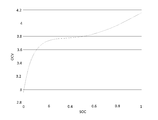
도 14는 휴대용 Li-이온 배터리 셀의 OCV-SOC 특성 곡선을 나타낸다.
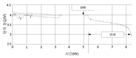
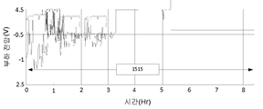
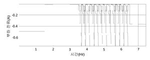
도 15a 및 15b는 부하 프로파일을 나타내는 그래프이다.
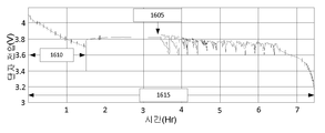
도 16a 및 16b는 시뮬레이션된 부하 프로파일을 나타내는 그래프이다.
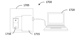
도 17은 예시적은 시스템 구현을 나타낸다.
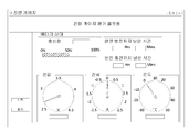
도 18은 시스템 구현과 함께 사용될 수 있는 사용자 인터페이스를 나타내는 도면이다.
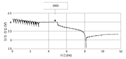
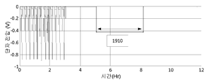
도 19a 및 19b는 예시적인 방전 전압/전류 프로파일을 나타내는 그래프를 포함한다.
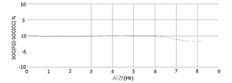
도 20a 및 20b는 예시적인 전류 적산 평가 방법을 나타내는 그래프이다.
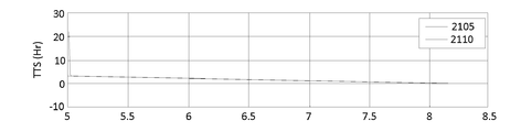
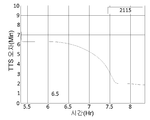
도 21a 및 21b는 셧다운 시각(TTS) 평가 방법을 나타내는 도면이다.
도 22a, 22b, 및 22c는 잔량 게이지 판독을 나타내는 표이다.
이들 도면은 특정의 예시적인 실시예에 사용된 방법 및/또는 구조의 개략적인 특성을 나타내고 이하 제공되는 기재된 설명을 보충하기 위한 것이다. 이들 도면은, 그러나, 축척대로 되어 있지 않으며 임의의 주어진 실시예의 정확한 구조 또는 성능 특성을 정확히 반영하지 않을 수 있으며 예시적인 실시예에 의해 포함되는 값 또는 속성의 범위를 정의 또는 제한하는 것으로 해석되어서는 안 된다. 예를 들어, 구조적 요소의 상대적인 두께 및 위치는 명확성을 위하여 감소되거나 과장될 수 있다. BRIEF DESCRIPTION OF THE DRAWINGS Exemplary embodiments will be more fully understood from the following detailed description and the accompanying drawings, taken in conjunction with the accompanying drawings, in which like elements are denoted by the same reference numerals, and are for purposes of illustration only and thus are not limitations of the exemplary embodiments .
Figures 1 and 2 show a block diagram of a battery management system (BMS) in accordance with at least one exemplary embodiment.
3 shows a block diagram of signal flow for selecting a battery equivalent model in accordance with at least one exemplary embodiment.
4 shows a blow diagram of a signal flow for computing a battery charge amount (SOC) according to at least one exemplary embodiment.
5 shows a block diagram of a battery fuel gauge (BFG) system in accordance with at least one exemplary embodiment.
6 shows a block diagram of signal flow for a parameter module of a BFG system according to at least one exemplary embodiment.
7 shows a block diagram of signal flow for a SOC module of a BFG system in accordance with at least one exemplary embodiment.
8 shows a block diagram of an SOC module in accordance with at least one exemplary embodiment.
9 shows a block diagram of a full least squares (TLS) module of a SOC module according to at least one exemplary embodiment.
10 shows a block diagram of a recursive least squares (RLS) module of an SOC module according to at least one exemplary embodiment.
Figures 11 and 12 show a sequence flow diagram of a method according to at least one exemplary embodiment.
Figures 13A-13D show schematic diagrams of a battery equivalent model according to at least one exemplary embodiment.
14 shows the OCV-SOC characteristic curve of the portable Li-ion battery cell.
15A and 15B are graphs showing load profiles.
16A and 16B are graphs showing the simulated load profile.
Figure 17 illustrates an exemplary system implementation.
18 is a diagram illustrating a user interface that may be used with a system implementation.
Figures 19a and 19b include a graph illustrating an exemplary discharge voltage / current profile.
20A and 20B are graphs showing an exemplary current integration evaluation method.
21A and 21B are views showing a method of evaluating the shutdown time (TTS).
Figures 22A, 22B, and 22C are tables showing residual gauge readings.
These drawings are intended to illustrate the approximate nature of the methods and / or structures used in the specific illustrative embodiments and to supplement the description provided below. These drawings, however, are not to scale and do not necessarily reflect the exact structure or performance characteristics of any given embodiment, and are to be construed as defining or limiting a range of values or attributes included by the exemplary embodiment Can not be done. For example, the relative thickness and location of structural elements may be reduced or exaggerated for clarity.
예시적인 실시예는 다양한 변형예 및 대체 형태를 포함할 수 있으나, 이들 실시예는 도면에서 예시로서 도시되고 본 명세서에서 상세하게 설명될 것이다. 그러나, 예시적인 실시예를 개시된 특정 형태로 제한하고자 하는 의도가 아니며, 이와는 반대로 예시적인 실시예는 청구범위의 범위 내에 있는 모든 변형예, 등가물, 그리고 대체물을 포함하는 것으로 이해되어야 한다. 발명의 상세한 설명과 도면 전체에 걸쳐 동일한 도면 부호는 동일한 요소를 나타낸다. The illustrative embodiments may include various modifications and alternative forms, but these embodiments are shown by way of example in the drawings and will be described in detail herein. It should be understood, however, that the intention is not to limit the exemplary embodiment to the specific forms disclosed, but on the contrary, the illustrative embodiments include all modifications, equivalents, and alternatives falling within the scope of the claims. Like reference numerals refer to like elements throughout the specification and drawings.
배터리 상태, 예컨대 충전량(state of charge: SOC), 건강 상태(state of health: SOH), 잔존 유효 수명(remaining useful life: RUL)의 정확한 추정은 배터리에 의해 구동되는 장치의 신뢰성 있고, 안전하며 광범위한 이용에 있어 중요하다. 이러한 양들을 추정하는 것은 배터리 잔량 게이지(battery fuel gauging: BFG)로 알려져 있다. 오늘날의 많은 자동차의 탄화수소 연료와 달리, 배터리의 저장 용량은 일정한 양이 아니다. 일반적으로, 배터리 용량이 배터리의 사용 기간(age), 사용 패턴 및 온도에 따라 가변됨으로써, BFG를 까다로운 적응형 추정 문제로 만들고 온도 변화, SOC 변동, 및 사용 기간에 걸쳐 배터리 특성의 모델링 및 온-라인 파라미터 식별을 요구한다. Accurate estimation of battery conditions, such as state of charge (SOC), state of health (SOH), and remaining useful life (RUL), is a reliable, It is important to use. Estimating these quantities is known as battery fuel gauging (BFG). Unlike the hydrocarbon fuels of many cars of today, the storage capacity of a battery is not constant. Generally, battery capacity varies with battery age, usage pattern, and temperature, thereby making BFG a challenging adaptive estimation problem and modeling battery characteristics over temperature, SOC variations, Requires line parameter identification.
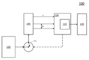
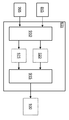
도 1 및 2는 적어도 하나의 예시적인 실시예에 따른 시스템(100)의 블록도를 나타낸다. 도 1에 도시된 바와 같이, 시스템(100)은 배터리(105), 배터리 관리 시스템(battery management system: BMS)(110), 디스플레이(120), 무제한 전원(125)(예컨대, 벽 콘센트(wall outlet), 자동차 충전소 등), 및 스위치(130)를 포함한다. Figures 1 and 2 illustrate a block diagram of a
BMS(110)는 배터리(105)의 이용 및/또는 상태를 관리하도록 구성될 수 있다. 예를 들어, BMS(110)는 스위치(130)를 이용하여 무제한 전원(125)을 배터리(105)에 접속 또는 접속 해제하여 배터리(105)를 충전하도록 구성될 수 있다. 예를 들어, BMS(110)는 부하(도시되지 않음)를 배터리(105)에 접속 또는 접속 해제하도록 구성될 수 있다. 예를 들어, BFG(115)는 배터리(105)의 충전량(SOC) 및/또는 건강 상태(SOH)를 연산하도록 구성될 수 있다. SOC 및/또는 SOH는 디스플레이(120) 상에 (예컨대, 백분율, 잔존 시간 등으로서) 디스플레이될 수 있다. The BMS 110 may be configured to manage usage and / or status of the
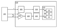
도 2에 도시된 바와 같이, BMS(110)는 적어도 아날로그 디지털 변환기(ADC)(205, 220), 필터(210, 225), 디지털 증폭기(215), 그리고 배터리 잔량 게이지(BFG)(115)를 포함한다. BFG(115)는 메모리(230), 프로세서(235), 그리고 제어기(240)를 포함한다. ADC(205, 220), 필터(210, 225), 디지털 증폭기(215), BFG(115) 중 적어도 하나는, 예를 들어, ASIC(application specific integrated circuit), DSP(digital signal processor), FPGA(field programmable gate array), 프로세서 등일 수 있다. 대안적으로, BMS(110)는 도시된 기능 블록을 포함하는 ASIC, DSP, FPGA, 프로세서 등일 수 있다. 대안적으로, 시스템(100)은 메모리에 저장되고 예를 들어 프로세서에 의해 실행되는 소프트웨어로서 구현될 수 있다. 2, the BMS 110 includes at least analogue digital converters (ADCs) 205 and 220,
BMS(110)는 디지털 변환기(ADC)(205, 220), 필터(210, 225), 그리고 디지털 증폭기(215)의 조합을 이용하여 아날로그 측정값(예컨대, Ib 및 Vb)을 디지털 값으로 변환하도록 구성될 수 있다(예컨대, SOC 및/또는 SOH를 연산하기 위하여 BFG(115)에 의해 사용하기 위함). 예를 들어, 디지털 증폭기(215)는 배터리(105) 양단의 전압 강하(Vb)(예컨대, 양극 단자와 음극 단자 사이의 전압 값의 차이)에 기초하여 아날로그 신호를 생성하는(예컨대, 생산하는) 차동 증폭기일 수 있으며, 이러한 아날로그 신호는 이후 ADC(220) 및 필터(225)를 이용하여 필터링된 디지털 값으로 변환된다. The BMS 110 uses a combination of digital converters (ADCs) 205 and 220,
시스템(100)은 전력을 제공하기 위하여 배터리를 이용하는 임의의 시스템 또는 전자 장치의 서브시스템일 수 있다. 일부 구현예에서, 전자 장치는, 예를 들어, 기존의 랩톱-타입 폼 팩터(form factor)를 갖는 랩톱-타입 장치이거나 이를 포함할 수 있다. 일부 구현예에서, 전자 장치는, 예를 들어, 유선 장치 및/또는 무선 장치(예컨대, Wi-Fi 가능 장치), 컴퓨팅 엔티티(예컨대, 개인 컴퓨팅 장치), 서버 장치(예컨대, 웹 서버), 장난감, 휴대 전화, 오디오 장치, 모터 제어 장치, 전원 공급 장치(예컨대, 오프-라인 전원 공급 장치), PDA(personal digital assistant), 태블릿 장치, e-리더(e-reader), 텔레비전, 자동차 등이거나 이를 포함할 수 있다. 일부 구현예에서, 전자 장치는, 예를 들어, 디스플레이 장치(예컨대, LCD(liquid crystal display) 모니터, 사용자에게 정보를 디스플레이하기 위함), 키보드, 포인팅 장치(pointing device)(예컨대, 마우스, 트랙패드, 사용자가 컴퓨터에 입력을 제공할 수 있는 장치)이거나 이를 포함할 수 있다.
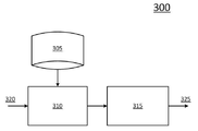
도 3은 적어도 하나의 예시적인 실시예에 따른 배터리 등가 모델을 선택하기 위한 신호 흐름의 블록도(300)를 나타낸다. 도 3에 도시된 바와 같이, 모델 선택 블록(310)은 입력(320)(예컨대, 배터리 및/또는 부하로부터의 전압 및/또는 전류 신호)을 수신하고 입력(320)(또는 그것의 몇 가지 변형)을 이용하여 등가 모델 라이브러리(equivalent model library)(305)로부터 배터리를 나타내는(또는 배터리에 대응하는) 등가 모델을 선택한다. 등가 모델은 그 다음 충전량 연산 블록(315)에 의해 충전량(SOC)을 연산하는데 사용된다. 등가 모델 라이브러리(305)는 배터리를 나타내는 적어도 하나의 등가 모델을 포함할 수 있다. 각각의 등가 모델은 배터리(또는 등가 배터리)의 동작 모드에 기초할 수 있다. 동작 모드는 배터리와 연관된 부하에 기초할 수 있다. 예를 들어, 동작 모드는 부하 양단의 전압 강하에 기초할 수 있다. 예를 들어, 동작 모드는 부하 양단의 전압 강하가 비교적 높거나 낮은지, 비교적 정적이거나 동적인지, 및/또는 그들의 조합에 기초할 수 있다. FIG. 3 shows a block diagram 300 of signal flow for selecting a battery equivalent model in accordance with at least one exemplary embodiment. 3,
등가 모델(이하의 도 13a 내지 13d 참조)은 저항, 전압(예컨대, 전압 강하 또는 전압원), 저항-전류(RC) 회로, 임피던스 회로, 및/또는 그밖에 유사한 것을 포함할 수 있다. 그러므로, 배터리의 등가 모델에 대한 수학적(예컨대, 공식) 등가물이 전개될 수 있다. 등가 모델 라이브러리(305)는 배터리의 동작 모드와 관련하여 수학적 등가물을 저장할 수 있다. 수학적 등가물은 충전량 연산 블록(315)에 의한 SOC의 연산에 사용될 수 있다. 예를 들어, 수학적 등가물은 SOC(또는 SOC의 추정치)를 연산하는데 사용되는 공식에 대한 입력으로서 변수들을 결정하는데 사용될 수 있다. 따라서 BFG 시스템은 동작 모드에 기초하여 등가 모델을 선택함으로써 연산 효율을 개선하고 처리 시간을 줄일 수 있다. 이하 더욱 상세한 설명이 도 5 내지 도 12와 관련하여 제공된다. The equivalent model (see Figures 13a-13d below) may include a resistor, a voltage (e.g., a voltage drop or voltage source), a resistive-current (RC) circuit, an impedance circuit, and / or the like. Therefore, a mathematical (e.g., formal) equivalent to an equivalent model of a battery can be developed. The
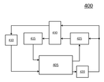
도 4는 적어도 하나의 예시적인 실시예에 따른 배터리 충전량(SOC)를 연산하기 위한 신호 흐름의 블록도(400)를 나타낸다. 도 4에 도시된 바와 같이, 블록도(400)는 확장 칼만 필터(extended Kalman filter: EKF) 블록(405), 층전량(SOC) 블록(410, 420), 필터 이득 파리미터 블록(415, 425) 및 버퍼(430)를 포함한다. EKF 블록(505)은 앞서 연산된 SOC(410)와 필터 이득 파라미터(415)에 기초하여 SOC(420)를 연산하고 필터 이득 파라미터들(425)(예컨대, 판독된 및/또는 연산된 SOC 분산(variance), 측정된 전압, 연산된 용량, 등가 회로와 연관된 변수, 및/또는 그밖에 유사한 것)를 결정하도록 구성될 수 있다. 이에 따라, 버퍼(430)는 앞서 계산된 SOC 및 필터 이득 파라미터를, 예를 들어 처리 루프(processing loop)에 저장하도록 구성될 수 있다. 즉, 현재(또는 다음) SOC는 앞서 연산된 적어도 하나의 SOC에 기초하여 연산될 수 있다. 달리 말하면, 제 1 시각에서 연산된 SOC는 제 2 시각(다음)에 SOC를 연산하는데 이용될 수 있다. FIG. 4 shows a block diagram 400 of a signal flow for computing a battery charge amount (SOC) in accordance with at least one exemplary embodiment. 4, the block diagram 400 includes an extended Kalman filter (EKF) block 405, a
예시적인 구현예에서, 적어도 두 개의 SOC(410) 및/또는 필터 이득 파라미터(415) 세트가 이용될 수 있다. 따라서, 적어도 두 개의 SOC의 벡터, 적어도 두 개의 SOC의 어레이, 적어도 두 개의 SOC의 평균(average), 및 적어도 두 개의 중간 값(mean), 그리고 대응하는 필터 이득 파라미터는 다음 SOC(420)(또는 제 2 시각에서의 SOC)를 연산하고 대응하는 필터 이득 파라미터(425)를 결정/연산하는데 사용될 수 있다. 이에 따라, 버퍼(430)는 앞서 연산된 복수의 SOC(410) 및 앞서 연산/결정된 필터 이득 파라미터(415)를 저장하도록 구성될 수 있다. 그러므로, BFG 시스템은 앞서 연산된 SOC를 이용함으로써 연산 효율을 개선하고 처리 시간을 줄일 수 있다. 이하 더욱 상세한 설명이 도 5 내지 도 12와 관련하여 제공된다. In an exemplary implementation, at least two
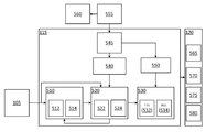
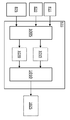
도 5는 적어도 하나의 예시적인 실시예에 따른 배터리 잔량 게이지(BFG)(115) 시스템의 블록도를 나타낸다. 도 5에 도시된 바와 같이, BFG(115)는 추정 모듈(510), 트래킹(tracking) 모듈(520), 예측 모듈(530), 개회로 전압-충전량(open circuit voltage-state of charge: OCV-SOC) 특성분석(characterization) 모듈(540), 오프라인(offline) 파라미터 추정 모듈(545) 및 배터리 수명 특성분석 모듈(550)을 포함한다. 또한, 시스템은 오프라인 데이터 수집 모듈(555) 및 배터리 모델링 모듈(560)을 포함한다. FIG. 5 shows a block diagram of a battery remaining gauge (BFG) 115 system in accordance with at least one exemplary embodiment. 5, the
오프라인 데이터 수집 모듈(555)은 비교적 제어된 테스트 환경에서 배터리 특성을 측정하도록 구성될 수 있다. 예를 들어, 개회로 전압(OCV) 측정값 및 SOC 측정값은 테스트 연구실 환경에서 배터리(105)(또는 등가 배터리)에 대해 수집될 수 있다. 예를 들어, 배터리(105)(또는 등가 배터리)는 완전히 충전된(에컨대, 거의 완전히 충전된, 실질적으로 완전히 충전된), 휴식(rested) 상태로 초기화될 수 있다. OCV 및 SOC 측정이 이루어질 수 있다. 그 다음 배터리(105)(또는 등가 배터리)가 완전히(또는 실질적으로) 방전될 때까지 간격을 두고(예컨대, 규칙적 간격, 주기적 간격, 불규칙적 간격, 미리 정해진 간격) OCV 및 SOC 측정이 이루어지면서 배터리(105)(또는 등가 배터리)는 서서히 방전될 수 있다. OCV 및 SOC 측정값은 배터리 파라미터(예컨대, 이하에 설명된 OCV 파라미터 Ki ∈ {K0;K1;K2;K3;K4;K5;K6;K7})를 결정, 연산 또는 추정하는데 이용될 수 있다. The offline
오프라인 데이터 수집 모듈(555)로부터의 데이터는 예를 들어 배터리(105)(또는 등가 배터리)에 대한 등가 모델 및/또는 이러한 등가 모델에 대한 수학적 등가물을 결정하기 위하여 배터리 모델링 모듈(560)에서 이용될 수 있다. 오프라인 데이터 수집 모듈(555)로부터의 데이터는 배터리(105)와 연관된 파라미터(예컨대, 앞서 언급된 등가 모델과 연관된 구성 요소에 대한 값들)를 결정 및/또는 연산하기 위하여 오프라인 파라미터 추정 모듈(545)에서 이용될 수 있다. 오프라인 데이터 수집 모듈(555)로부터의 데이터는 OCV 및 SOC 배터리 파라미터(예컨대, 이하에 설명된 OCV 파라미터 Ki ∈ {K0;K1;K2;K3;K4;K5;K6;K7})를 결정 및/또는 연산하기 위하여 OCV-SOC 특성분석 모듈(540)에서 이용될 수 있다. 오프라인 파라미터 추정 모듈(545)로부터의 데이터는 배터리 수명 특성분석 모듈(550)에서 이용될 수 있다. 예를 들어, 오프라인 파라미터 추정 모듈(545)로부터의 데이터는 배터리 수명 특성분석 모듈(550)에 의해 초기 SOH 특성(예컨대, 최대 SOC)을 연산하는데 이용될 수 있다. Data from the off-line
디스플레이(120)는 SOC 디스플레이(565), SOH 디스플레이(570), 셧다운 시각(time to shutdown: TTS) 디스플레이(575), 그리고 잔존 유효 수명 디스플레이(580)를 갖는 것으로 도시되어 있다. 각각의 디스플레이는, 예를 들어, 백분율을 보여주는 계량기(meter)일 수 있다. 각각의 디스플레이에 대한 값들은 BFG(115)에 의해 연산 또는 결정될 수 있다. 예를 들어, TTS는 TTS 모듈(532)에 의해 연산된 시간 값(예컨대, 시간 및/또는 분)으로서 디스플레이될 수 있다. The
추정 모듈(510)은 파라미터 모듈(512) 및 용량 모듈(514)을 포함한다. 추정 모듈(510)은 배터리(105)(또는 등가 배터리)에 대해 특정한 값들(예컨대, 파라미터 및 용량 값들)을 연산 및/또는 결정하도록 구성될 수 있다. 안정된 환경에서(예컨대, 테스트 연구실) 파라미터 및 용량 값들은 고정될 수 있다(즉, 변하지 않음). 그러나, 실제 환경에서 파라미터 및 용량 값들은 동적이거나 가변할 수 있다. 예를 들어, 완전한 SOC 트래킹 솔루션은 일반적으로 (1) 오프라인 OCV 특성분석을 통한 상태 공간 모델의 일부를 형성하는 OCV 파라미터의 추정을 포함한다. OCV-SOC 특성분석은 온도 변화와 배터리의 노화에 대해 안정적이다. 일단 추정되면, 이들 파라미터는 알려진 파라미터와 함께 상태 공간 모델의 일부를 형성한다. 완전한 SOC 트래킹 솔루션은 일반적으로 (2) 동적 전기적 등가 회로 파라미터의 추정을 포함한다. 이들 파라미터는 온도, SOC 및 배터리의 사용 기간에 따라 가변하는 것으로 관찰되었고 이런 이유로 BFG가 동작하는 동안 적응적으로 추정되어야 한다. 완전한 SOC 트래킹 솔루션은 일반적으로 (3) 배터리 용량의 추정을 포함한다. 배터리의 규격 용량(nominal capacity)이 제조자에 의해 특정되더라도, 사용 가능한 배터리 용량은 제조 공정에서의 오차, 온도 변화, 사용 패턴, 그리고 노화로 인하여 변하는 것으로 알려져 있다. 그리고 완전한 SOC 트래킹 솔루션은 일반적으로 (4) 모델 파라미터-조건부 SOC 트래킹을 포함한다. 모델 파라미터가 일단 알려지면, SOC 트래킹은 비선형 필터링 문제가 된다. 그러나, 결과적인 상태 공간 모델이 상호 연관된(correlated) 공정 및 측정 노이즈 공정을 포함하는 것으로 관찰된다. 이들 상관관계의 효과를 적절히 해결하면 더 나은 SOC 트래킹 정확도를 얻을 것이다. 따라서, 예시적인 구현예에서, 파라미터 및 용량을 연산하기 위하여, 트래킹 모듈(520)은 추정 모듈(510)로 데이터를 피드백할 수 있다. The
또한, 배터리 용량을 추정하는 일반적인 방법들은 히스테리시스 효과(hysteresis effect)를 무시하고 잔여(rested) 배터리 전압이 배터리의 진정한 개회로 전압(OCV)을 나타내는 것이라고 가정한다. 그러나, 예시적인 실시예에 따르면, 추정 모듈(510)은 배터리(105)의 OCV에서의 오차로서 히스테리시스를 모델링하고 실제 시간, 선형 파라미터 추정 및 SOC 트래킹 기술의 조합을 채택하여 OCV에서의 오차를 보상한다. In addition, common methods for estimating battery capacity assume that the rested battery voltage is indicative of the battery's true open circuit voltage (OCV), ignoring the hysteresis effect. However, according to an exemplary embodiment, the
트래킹 모듈(520)은 SOC 모듈(522) 및 SOH 모듈(524)을 포함한다. SOC는 배터리(105) 내의 "잔량(fuel)"의 양을 나타낸다. 앞서 설명한 바와 같이, SOC는 몇 가지 기준(예컨대, 정격 용량 또는 전류 용량)의 백분율로서 표현된 이용 가능한 용량이다. 예시적인 실시예에 따르면, SOC 모듈(522)은 트래킹을 이용하여 SOC를 연산함으로써 이하에서 더욱 상세하게 설명되는 OCV에서의 오차를 보상한다(파라미터 추정과 조합하여). SOH는 새로운 배터리 또는 이상적인 배터리와 비교한 배터리의 상태를 나타낸다. SOH는 충전 수용(charge acceptance), 내부 저항, 전압, 자가-방전 및/또는 그밖에 유사한 것에 기초할 수 있다. The
예측 모듈(530)은 TTS 모듈(532) 및 RUL 모듈(534)을 포함한다. TTS 모듈(532) 및 RUL 모듈(534)은 SOC에 기초하여 TTS 및 RUL을 연산하도록 구성될 수 있다. The
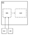
도 6은 적어도 하나의 예시적인 실시예에 따른 BFG(115)의 파라미터 모듈(412)에 대한 신호 흐름의 블록도를 나타낸다. BFG 시스템은 동작 모드에 기초하여 등가 모델을 선택함으로써 연산 효율을 개선하고 처리 시간을 줄일 수 있다. 도 6에 도시된 바와 같이, 파라미터 모듈(412)은 동작 모드 모듈(605) 및 모델 선택 모듈(610)을 포함한다. 동작 모드 모듈(605)은 배터리(105)로부터의 적어도 하나의 입력 및/또는 부하(615)로부터의 적어도 하나의 입력에 기초하여 (배터리의) 동작 모드를 결정하도록 구성될 수 있다. 이러한 적어도 하나의 입력은 배터리(105) 및 부하(615) 중 적어도 하나와 연관된 전류 및 전압 중 적어도 하나에 기초할 수 있다. 예를 들어, 동작 모드는 부하(615) 양단의 전압 강하에 기초할 수 있다. 예를 들어, 동작 모드는 부하 양단의 전압 강하가 비교적 높거나 낮은지, 비교적 정적이거나 동적인지, 및/또는 그들의 조합에 기초할 수 있다. 모델 선택 모듈(610)은 결정된 동작 모드에 기초하여 등가 모델(또는 그것의 수학적 등가물)을 선택할 수 있다. 예를 들어, 모델 선택 모듈(610)은 등가 모델 라이브러리(305)를 검색하는데 사용되는 질의어(query term)를 생성할 수 있다. FIG. 6 shows a block diagram of signal flow for a
일부 구현예에서, 몇 가지 동작 모드가 정의 또는 특성화될 수 있다. 예시적인 구현예에서, 배터리 및 이러한 배터리를 이용하는 시스템과 연관된 네 개의 동작 모드가 이하 설명된다. In some implementations, several modes of operation may be defined or characterized. In an exemplary embodiment, four modes of operation associated with a battery and a system using such a battery are described below.
제1 동작 모드에서, 배터리(105)는 가변 중부하(heavy and varying load)에 연결될 수 있다. 달리 말하면, 부하(615)가 동적 또는 가변 전류 소모와 함께 비교적 높은 전압을 이용할 수 있다(또는 가변 전류를 소모하는 고전압 부하). 예를 들어, 휴대 전화에서, 제1 동작 모드는 휴대 전화 사용이 장시간의 비디오 재생, 멀티미디어 및 게임 어플리케이션 등을 포함하는 사용 환경을 포함할 수 있다. 이하의 도 13a에 도시된 등가 회로는 가변 중부하에 연결된 배터리를 나타낼 수 있다. In the first mode of operation, the
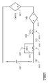
제2 동작 모드에서, 배터리(105)는 동적 부하 및/또는 가변 전압 부하에 연결될 수 있다. 달리 말하면, 부하(615)는 동적 전압 또는 가변 전압을 이용할 수 있다. 예를 들어, 휴대 전화에서, 제2 동작 모드는 휴대 전화 사용이 전화 통화를 위한 규칙적인 사용, 웹 브라우징 및/또는 비디오 클립 재생을 포함하는 사용 환경을 포함할 수 있다. 이하의 도 13b에 도시된 등가 회로는 동적 부하에 연결된 배터리를 나타낼 수 있다. In the second mode of operation, the
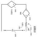
제3 동작 모드에서, 배터리(105)는 정전류(constant current)를 소모하는 부하에 연결될 수 있다. 달리 말하면, 부하(615)는 일정한 (또는 실질적으로 일정한) 전류를 소모할 수 있다. 대안적으로, 배터리(105)는 정전류를 이용하여 충전될 수 있다. 예를 들어, 배터리(105)는 충전 사이클 동안 부하(615)로부터 접속 해제될 수 있다(예컨대, 무제한 전원(125)이 스위치(130)를 이용하여 배터리(105)에 접속되어 배터리(105)를 충전할 수 있음). 이하의 도 13c에 도시된 등가 회로는 정전류에 연결된 배터리를 나타낼 수 있다. In the third mode of operation, the
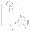
제4 동작 모드에서, 배터리(105)는 비교적 저전압 부하에 연결될 수 있다. 대안적으로, 배터리(105)는 경부하(light loading)에 이어서 충전, 그 후에 휴식, 최소의 부하 또는 무부하를 겪는 주기적인 휴식 상태에 있을 수 있다. 달리 말하면, 부하(615)가 드물게 최소의 전압을 이용할 수 있다. 예를 들어, 휴대 전화에서, 제4 동작 모드는 휴대 전화 사용이 완전 충전(또는 실질적으로 완전 충전) 후에 드문 전화 통화와 함께 송신탑의 규칙적인 핑(ping)을 포함하는 사용 환경을 포함한다. 이하의 도 13d에 도시된 등가 회로는 저전압 부하에 연결된 배터리를 나타낼 수 있다. In the fourth mode of operation, the
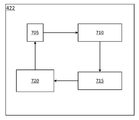
도 7은 적어도 하나의 예시적인 실시예에 따른 BFG(115)의 SOC 모듈(422)에 대한 신호 흐름의 블록도를 나타낸다. 도 7에 도시된 바와 같이, SOC 모듈(422)은 버퍼 블록(705), 모델 추정 블록(710), SOC 트래킹 블록(715), 그리고 전압 강하 예상 모듈 또는 블록(720)을 포함한다. FIG. 7 shows a block diagram of signal flow to the
예시적인 실시예에서, 히스테리시스가 배터리(105)의 OCV에서의 오차로서 모델링된다. 전압 강하 vD[k]는 배터리 모델 내부 구성 요소 R0, R1, R2 및 xh[k] 양단의 전압을 나타낼 수 있다(도 13a 참조). 용어 xh[k]는 예상된 SOC에서의 오차를 설명하는데 이용될 수 있다. 즉, xh[k]는 연산된 또는 추정된 SOC를 조정함으로써 영(zero)으로 수정될 수 있는 "순시 히스테리시스(instantaneous hysteresis)"일 수 있다. 연산된 또는 추정된 SOC가 SOC와 동일한 경우, 연산된 또는 추정된 xh[k]는 영(zero)과 동일하여야 한다. 달리 말하면, 영이 아닌 연산된 또는 추정된 xh[k]는 연산된 또는 추정된 SOC에서의 오차를 나타낸다. 전압 강하 모델 파라미터 벡터(b)는 연산된 또는 추정된 xh[k]에 대응하는 요소를 포함한다. In the exemplary embodiment, hysteresis is modeled as an error in the OCV of the
이에 따라, 도 7의 흐름에서, SOC 트래킹 블록(715)으로부터의 연산된 또는 추정된 현재 SOC는, 전압 강하 vD[k]를 계산하기 위하여 전압 강하 예상 블록(720)에서 이용된다. 적어도 하나의 과거 전압 강하 vD[k]는 버퍼(705)에 저장되고 파라미터 벡터 b의 추정에 이용된다. 파라미터 벡터 b에서의 대응하는 연산된 또는 추정된 xh[k]의 영이 아닌 값은 순시 히스테리시스의 존재를 나타낸다. 이는 SOC 추정 오차를 의미한다. SOC 트래킹 블록(715)의 SOC 트래킹 알고리즘은 연산된 또는 추정된 xh[k]가 영이 아닐 때마다 SOC를 수정하도록 구성된다. 전압 강하 vD[k], 히스테리시스, 추정된 xh[k], 전압 강하 모델 파라미터 벡터(b) 및 SOC 트래킹에 관한 추가의 세부 사항이 이하에서 (수학적으로) 설명된다. 이와 같이 BFG 시스템은 앞서 연산된 SOC 및 SOC 오차를 이용함으로써 SOC를 정확하게 추정하고 연산 효율을 개선하며, 처리 시간을 줄일 수 있다. 7, the computed or estimated current SOC from the
도 8은 적어도 하나의 예시적인 실시예에 따른 SOC 모듈(422)의 블록도를 나타낸다. 도 8에 도시된 바와 같이, SOC 모듈(422)은 확장 칼만 필터(EKF) 블록(805)을 포함한다. EKF 블록은 SOC(845) 및 SOC 오차(840)를 연산하도록 구성될 수 있다. EKF 블록(805)은 식 (1)을 이용하여 SOC(845)를 추정된 SOC로서 연산하고, 식 (2)를 이용하여 SOC 오차(840)을 추정된 SOC 오차(또는 분산)로서 연산하도록 구성될 수 있다. 이하의 각각의 식에서, k는 순시 반복(instantaneous iteration)을 나타내고, k+1|k는 마지막, 앞선 또는 이전의 반복을 나타내며, k+1|k+1은 현재, 업데이트, 다음 또는 차후의 반복을 나타낸다. FIG. 8 shows a block diagram of a
![]()
![]()
여기서, ![]()
![]()
![]()
![]()
![]()
![]()
![]()
![]()

여기서, ![]()
![]()
![]()
![]()
![]()
![]()
![]()
![]()
![]()
![]()
SOC 모듈(422)은 OCV 파라미터 블록(810)을 포함한다. OCV 파라미터 블록(810)은 OCV-SOC 특성분석 모듈(540)로부터의 OCV 파라미터 {Ki}를 저장 및/또는 수신하도록 구성될 수 있다. OCV 파리미터 {Ki}는 그들이 오프라인에서 측정되고 배터리(105)의 수명에 대한 변화가 무시할 수 있을 정도(또는 존재하지 않음)라는 점에서 일정하다. OCV 파라미터는 식 (3)에 따라 SOC에 관해서 OCV를 연산하는데 이용된다. The

여기서, ![]()
![]()
![]()
![]()
SOC 모듈(422)은 전압 강하 모델 블록(825)을 포함한다. 전압 강하 모델 블록(825)은 식 (4) 또는 식 (5)에 따라 (앞서 설명된) 전압 강하 모델을 이용하여 부하 양단의 전압 강하를 연산하도록 구성될 수 있다. The
![]()
![]()
![]()
![]()
여기서, ![]()
![]()
![]()
![]()
![]()
![]()
![]()
![]()
![]()
![]()
![]()
![]()
![]()
![]()
전압 강하 모델은 앞서 설명된 바와 같이 선택된 등가 회로 모델에 기초하여 가변할 수 있다. 선택된 등가 회로 모델 및/또는 전압 강하 모델은 데이터 저장부(855)로부터 판독될 수 있다. 예를 들어, 데이터 저장부(855)는 등가 모델 라이브러리(305)를 포함할 수 있다. The voltage drop model can be varied based on the selected equivalent circuit model as described above. The selected equivalent circuit model and / or voltage drop model may be read from the
EKF (모듈 또는) 블록(805)은 식 (1)을 이용하여 SOC(845)를 추정된 SOC로서 연산하고 그 결과 얻어진 SOC(845)를 버퍼(850)에 저장하도록 구성될 수 있다. EKF 블록(805)은 식 (2)를 이용하여 SOC 오차(840)를 추정된 SOC 오차(또는 분산)로서 연산하고 그 결과 얻어진 SOC 오차(840)를 버퍼(850)에 저장하도록 구성될 수 있다. 저장된 SOC 및 SOC 오차는 SOC(815) 및 SOC 오차(820)로서 판독될 수 있다. 이에 따라 EKF 블록은, 차후의(업데이트, 다음, 및/또는 시간적으로 이후의) SOC(845) 및 SOC 오차(840) 연산이 적어도 하나의 이전(현재, 마지막 또는 시간적으로 이전의) SOC(815) 및 SOC 오차(820) 연산에 기초할 수 있도록, SOC(845) 및 SOC 오차(840)를 재귀적으로(예컨대, 루프에서) 연산할 수 있다. The EKF (module or) block 805 may be configured to use the equation (1) to calculate the
도 8에 도시된 바와 같이, 재귀 최소자승(RLS: Recursive least squared) 블록(830) 및 전 최소자승(TLS: Total Least Squared) 블록(835)은 EKF 블록(805)으로의 입력을 생성할 수 있다. RLS 블록은 초기의 추정된 전압 강하 모델 파라미터 벡터(적어도 하나의 전압 강하 모델 파라미터를 포함할 수 있음)를 생성할 수 있고, TLS 블록(835)은 초기의 추정된 용량을 생성할 수 있다. 이러한 초기의 추정된 전압 강하 모델 파라미터 벡터 및 초기의 추정된 용량은 각각의 루프에 대해 생성될 수 있다. 예시적인 구현예에서, 반복 회수(k)가 증가함에 따라 초기의 추정된 전압 강하 모델 파라미터 벡터 및 초기의 추정된 용량의 변화는 무시할만한 정도가 될 수 있다. 8, a Recursive least squared (RLS) block 830 and a Total Least Squared (TLS) block 835 may generate an input to the EKF block 805 have. The RLS block may generate an initial estimated voltage drop model parameter vector (which may include at least one voltage drop model parameter) and the TLS block 835 may generate an initial estimated capacity. This initial estimated voltage drop model parameter vector and initial estimated capacity can be generated for each loop. In an exemplary implementation, as the number of iterations k increases, the initial estimated voltage drop model parameter vector and the change in the initial estimated capacity may be negligible.
도 9는 적어도 하나의 예시적인 구현예에 따른 SOC 모듈(422)의 전 최소자승(TLS) 블록(835)에 대한 블록도이다. 도 9에 도시된 바와 같이, TLS 블록(635)은 버퍼(910) 및 TLS 연산 모듈(915)을 포함한다. 버퍼(910)는 TLS 연산 모듈(915)에 의해 이용되도록 SOC 데이터, 예를 들어 SOC 변화량(또는 변화) 데이터(920)를 수신, 저장, 및 출력하도록 구성된다. 버퍼(910)는 TLS 연산 모듈(915)에 의해 이용되도록 전류 변화량(또는 변화) 데이터(925)를 수신, 저장, 및 출력하도록 더 구성된다. 버퍼(910)는 예를 들어 배터리(105)와 관련되는 측정된 전류에 기초하여 전류 적산(coulomb counting) 데이터로서 전류 데이터(905)를 수신할 수 있다.9 is a block diagram of a full least squares (TLS) block 835 of the
TLS 연산 모듈(915)은 SOC 변화량(920) 및 전류 변화량(925)에 기초하여 배터리(105)의 용량(930)을 연산하도록 구성될 수 있다. 예를 들어, TLS 연산 모듈(915)은 수학식(6)을 이용하여 용량(930)을 연산할 수 있다. 수학식(6)의 편차에 대해서는 아래에서 보다 상세하게 설명할 것이다.The
![]()
![]()
여기서, ![]()
![]()
![]()
![]()
![]()
![]()
도 10은 적어도 하나의 예시적인 실시예에 따른 SOC 모듈(422)의 재귀 최소자승(RLS) 블록(830)의 블록도이다. 도 10에 도시된 바와 같이, RLS 블록(635)은 버퍼(1005) 및 RLC 연산 모듈(1010)을 포함한다. 버퍼(1005)는 전압 강하 모델 블록(825)으로부터 출력으로서 SOC(815), SOC 오차(820) 및 전압 강하 데이터(예컨대, Zv[k] 또는 OCV)를 수신 및 저장하도록 구성된다. 버퍼(1005)는 전압 강하(1015), 그리고 전류 및 커패시턴스(I&C) 매트릭스(1020)를 출력하도록 구성된다.10 is a block diagram of a recursive least squares (RLS) block 830 of the
RLC 연산 모듈(1010)은 전압 강하(1015) 및 I&C 매트릭스(1020)에 기초하여 초기화 파라미터(1025)를 연산하도록 구성될 수 있다. 예를 들어, RLC 연산 모듈(1010)은 수학식(7)을 이용하여 초기화 파라미터(1025)를 연산할 수 있다. 수학식(7)의 편차에 대해서는 아래에서 보다 상세하게 설명할 것이다.The

여기서, αi는 R1C1 회로에서의 전류 감쇠 계수이고, Where a i is the current attenuation coefficient in the R 1 C 1 circuit,
βi는 R2C2 회로에서의 전류 감쇠 계수이며, β i is the current attenuation coefficient in the R 2 C 2 circuit,
![]()
![]()
![]()
![]()
![]()
![]()
![]()
![]()
위에서 도 7과 관련하여 기술된 바와 같이, 배터리의 추정된 히스테리시스 전압은 0(zero)이 될 것이다. 따라서, 예시적인 구현예에서 수학식(7)의 b(6)는, SOC 트랙킹을 이용하여 히스테리시스에 기인하는 오차를 제거(또는 실질적으로 제거)하기 위해 SOC 트랙킹 블록(715)을 이용하면 0이 될 것이다. 따라서, 히스테리시스가 고려될 수 있으므로 SOC 추정은 보다 정확하다.As described above with respect to FIG. 7 above, the estimated hysteresis voltage of the battery will be zero. Thus, in an exemplary implementation, b (6) in Equation (7) can be computed using
도 8-10에서, 버퍼(1005) 길이는 파라미터 추정에 대해 Lb일 수 있고, 버퍼(905) 길이는 용량 추정에 대해 Lc일 수 있다. EKF 블록(805)은 매 k 마다 반복되고, RLS(830)는 Lb의 정수배인 매 k 마다 반복되며, TLS(835)는 Lc의 정수배인 매 k 마다 반복되고, 여기서 k는 시간 인덱스이다. BFG는, (오프라인으로 추정되는) OCV 파라미터를 제외하고 모든 필요한 모델 파라미터와 SOC 트랙킹에 필요한 배터리 용량, 그리고 측정 기구 회로의 교정(calibration)으로부터 발생하는 전압 및 전류 측정 오차 표준 편차(![]()
![]()
![]()


![]()
![]()
![]()
도 11 및 12는 적어도 하나의 예시적인 실시예에 따른 방법의 흐름도이다. 도 11 및 12과 관련하여 기술되는 단계는, 장치(예컨대, 도 1 및 2에 도시된 BMS(110))와 연관된 메모리(예를 들어, 메모리(230))에 저장되어 이러한 장치와 연관된 적어도 하나의 프로세서(예를 들어, 프로세서(235))에 의해 실행되는 소프트웨어 코드의 실행으로 수행될 수 있다. 그러나, 전용 프로세서로서 구현되는 시스템과 같은 대안적인 구현예도 예상된다. 이하 기술하는 단계는 예를 들어 프로세서에 의해 실행되는 것으로 기술되지만, 이러한 단계는 반드시 동일한 프로세서에 의해 실행되는 것은 아니다. 달리 말하면, 적어도 하나의 프로세서가 도 11 및 12와 관련하여 이하 기술되는 단계를 실행할 수 있다.11 and 12 are flowcharts of a method according to at least one exemplary embodiment. The steps described in connection with Figures 11 and 12 may be stored in a memory (e.g., memory 230) associated with a device (e.g.,
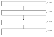
도 11은 추정된 SOC를 연산하는데 이용하기 위해 배터리를 나타내는 등가 모델을 선택하기 위한 방법의 흐름도이다. 도 11에 도시된 바와 같이, 단계(S1105)에서는 배터리를 나타내는 등가 회로 모델의 라이브러리가 메모리에 저장된다. 예를 들어, 오프라인 데이터 수집 모듈(555)을 이용하여 배터리(105)(또는 등가 배터리)와 연관된 데이터가 수집될 수 있다. 데이터 및 일반적인 회로 툴을 이용하여, 배터리를 나타내는 적어도 하나의 등가 회로가 생성될 수 있다. 이러한 등가 회로는 적어도 하나의 등가 전압, 저항, 커패시턴스, 및/또는 임피던스 등가물의 임의의 조합을 포함할 수 있다. 예를 들어 이하의 도 13a-13d를 참조할 수 있다. 각각의 등가 회로에 대한 수학적 등가물 또한 생성될 수 있다. 등가 회로 및/또는 수학적 등가물은, 예를 들어 등가 모델 라이브러리(305)에 저장될 수 있다.11 is a flowchart of a method for selecting an equivalent model representing a battery for use in computing an estimated SOC. As shown in Fig. 11, in step S1105, a library of an equivalent circuit model representing a battery is stored in a memory. For example, data associated with the battery 105 (or equivalent battery) may be collected using the offline
단계(S1110)에서, 배터리의 동작 모드가 배터리와 연관된 부하에 기초하여 결정된다. 예를 들어 각각의 등가 모델은 배터리(또는 등가 배터리)의 동작 모드에 기초할 수 있다. 동작 모드는 배터리와 연관된 부하에 기초할 수 있다. 예를 들어, 동작 모드는 부하 양단의 전압 강하에 기초할 수 있다. 예를 들어, 동작 모드는 부하 양단의 전압 강하가 비교적 높은지 또는 낮은지, 비교적 일정한지 또는 동적인지, 및/또는 이들의 조합인지 여부에 기초할 수 있다. 그러므로, 동작 모드는 배터리와 연관된 전류 및/또는 전압 및/또는 배터리와 연관된 부하에 기초하여 결정될 수 있다.In step S1110, the operating mode of the battery is determined based on the load associated with the battery. For example, each equivalent model may be based on the operating mode of the battery (or equivalent battery). The mode of operation may be based on the load associated with the battery. For example, the operating mode may be based on a voltage drop across the load. For example, the mode of operation may be based on whether the voltage drop across the load is relatively high or low, relatively constant or dynamic, and / or a combination thereof. Therefore, the operating mode can be determined based on the current and / or voltage associated with the battery and / or the load associated with the battery.
단계(S1115)에서, 결정된 모드에 대한 등가 회로 모델 중 하나가 결정된 모드에 기초하여 선택된다. 예를 들어, 등가 모델 라이브러리(305)는 결정된 동작 모드에 기초하여 탐색될 수 있다. 예를 들어, 배터리를 나타내는 등가 회로 및/또는 수학적 등가물이 동작 모드 식별자(예를 들어, 고유 명칭 또는 고유 식별 번호)와 부합하여 등가 모델 라이브러리(305)에 저장될 수 있다. 따라서, 동작 모드의 결정은, 이후 등가 모델 라이브러리(305)를 탐색하는데 이용되는 동작 모드 식별자를 결정하는 것을 포함할 수 있다. 등가 회로의 선택은 등가 모델 라이브러리(305)의 탐색에 의해 반환되는 등가 회로 또는 수학적 등가물을 선택하는 것을 포함할 수 있다.In step S1115, one of the equivalent circuit models for the determined mode is selected based on the determined mode. For example, the
단계(S1120)에서, 배터리의 충전량(SOC), 또는 추정된 SOC가 선택된 등가 회로 모델을 이용하여 연산된다. 예를 들어, 위에서 기술된 바와 같이, SOC의 연산은 전압 강하 모델 파라미터 벡터(b)에 기초할 수 있다. 전압 강하 모델 파라미터 벡터는 배터리의 등가 회로에 기초하는 파라미터를 가질 수 있다(위의 수학식(7) 참조). 따라서, 결정된 전압 강하 모델 파라미터 벡터는 등가 회로에 기초하여 다소 복잡할 수 있다. 예를 들어, 이하 기술되는 바와 같이, 등가 회로는 커패시터가 충전되어 저항을 바이패스하기 때문에 RC 회로 요소를 포함하지 않을 수 있다. 따라서, b(3)는 유일하게 남아 있는 전압 강하 모델 파라미터 벡터 요소일 수 있다. 이런 식으로 SOC 또는 추정된 SOC의 연산이 단순화된다. 나아가, SOC 또는 추정된 SOC를 연산하는데 이용될 수 있는 배터리(105) 단자 양단의 전압(v[k])이 등가 회로 모델에 기초할 수 있다. v[k], SOC, 및 등가 회로 모델을 관련시키는 수학식에 대해 이하 보다 상세하게 기술할 것이다.In step S1120, the charge amount SOC of the battery or the estimated SOC is calculated using the selected equivalent circuit model. For example, as described above, the operation of the SOC may be based on the voltage drop model parameter vector (b). The voltage drop model parameter vector may have parameters based on the equivalent circuit of the battery (see equation (7) above). Thus, the determined voltage drop model parameter vector can be somewhat complex based on an equivalent circuit. For example, as described below, an equivalent circuit may not include an RC circuit element because the capacitor is charged to bypass the resistor. Thus, b (3) may be the only remaining voltage drop model parameter vector element. In this way, the calculation of SOC or estimated SOC is simplified. Further, the voltage v [k] across the terminal of the
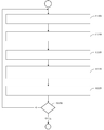
도 12는 순환 필터를 이용하여 추정된 SOC를 연산하기 위한 방법의 흐름도이다. 도 12에 도시된 바와 같이, 단계(S1205)에서는 배터리의 저장되어 있는 추정된 충전량(SOC)이 버퍼로부터 판독된다. 예를 들어, 버퍼(850)에는 적어도 하나의 SOC 오차, 및 이러한 흐름도와 관련하여 기술된 단계의 이전 반복에서 연산된 SOC가 저장되어 있을 수 있다. 저장된 SOC 값 중 적어도 하나가 버퍼(850)로부터 판독될 수 있다.12 is a flowchart of a method for calculating an estimated SOC using a cyclic filter. As shown in Fig. 12, in step S1205, the stored estimated charge amount SOC of the battery is read from the buffer. For example, the
단계(S1210)에서, 배터리 양단의 측정된 전압이 판독된다. 예를 들어, 전압(예컨대, 이하 도 13a-13d에 도시된 v[k])이 판독되거나 예를 들어 디지털 증폭기(215)를 이용하여 결정될 수 있다. 하나의 예시적인 구현예에서, 이러한 전압은 버퍼에 저장된다. 따라서, 상이한 반복이 상이한 전압 측정을 이용할 수 있다. 달리 말하면, (시간상) 이전의 전압 측정이 현재의 반복에서 이용될 수 있거나, v[k+1]이 반복(k+2)에서 이용될 수 있다. In step S1210, the measured voltage across the battery is read. For example, a voltage (e.g., v [k] shown in Figures 13A-13D below) may be read or determined, for example, using
단계(S1215)에서 필터 이득이 연산된다. 예를 들어, 위에서 간략이 기술되고 이하 보다 상세하게 기술되는 바와 같이, EKF 블록(805)에 대한 필터 이득(예컨대, G[k+1])이 연산된다. 필터 이득은 가중 최소자승 알고리즘을 이용하여 연산된 적어도 하나의 용량 값에 기초할 수 있다. 예를 들어, 필터 이득은 가중 재귀 최소자승(RLS) 알고리즘 및 전 최소자승(TLS) 알고리즘 중 적어도 하나를 이용하여 연산된 적어도 하나의 용량 값에 기초할 수 있다. 필터 이득은 SOC 트랙킹 오차 공분산 및 전류 측정 오차 표준 편차에 기초하여 가중 RLS 알고리즘을 이용해서 연산된 용량 값에 기초할 수 있다. 필터 이득은 추정된 SOC 분산에 기초할 수 있다. 필터 이득은 공분산 행렬의 재귀적 업데이트에 기초하여 TLS 알고리즘을 이용해서 연산된 용량 값에 기초할 수 있다. 필터 이득은 개방 회로 전압(OCV) 룩업을 이용하여 연산된 용량 값에 기초할 수 있다. SOC 트랙킹 오차 공분산, 전류 측정 오차 표준 편차, SOC 분산, 공분산 행렬 및 OCV의 각각에 대해 이하 보다 상세하게(예를 들면, 수학적으로) 기술할 것이다.In step S1215, the filter gain is calculated. For example, a filter gain (e.g., G [k + 1]) for
단계(S1220)에서, 배터리의 추정된 SOC는 배터리의 저장된 SOC, 배터리 양단의 전압 및 필터 이득에 기초하여 연산된다. 예를 들어, 추정된 SOC는 저장되어 있는 추정된 SOC 더하기 디지털 전압값 곱하기 필터 이득과 동일할 수 있다. 단계(S1225)에서, 연산되는 추정된 SOC는 버퍼(예컨대, 버퍼(850))에 저장된다. 추정된 SOC의 추가적인 연산이 필요하고 및/또는 바람직한 경우(S1230), 처리는 단계(1205)로 복귀한다. 예를 들어, 배터리(105)가 계속 이용 중인 경우, SOC 오차가 요구되는 값을 초과하고 추가적인 반복이 오차를 줄일 수 있는 경우, 배터리 테스트가 진행 중인 경우 및/또는 이와 유사한 경우에 추가적인 연산이 필요하고 및/또는 바람직할 수 있다. In step S1220, the estimated SOC of the battery is calculated based on the stored SOC of the battery, the voltage across the battery, and the filter gain. For example, the estimated SOC may be equal to the stored estimated SOC plus digital voltage value multiplication filter gain. In step S1225, the estimated SOC computed is stored in a buffer (e.g., buffer 850). If additional computation of the estimated SOC is required and / or desired (S1230), the process returns to step 1205. [ For example, if the
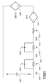
도 13a-13d는 적어도 하나의 예시적인 실시예에 따른 배터리 등가 모델의 개략적인 다이어그램을 나타낸다. 하나 이상의 예시적인 구현예를 기술하기 위해 이하에서는 필요한 경우 도 13a-13d를 참조할 것이다. 도 13a-13d에 도시된 바와 같이, 배터리(1300-1, 1300-2, 1300-3, 1300-4)를 나타내는 등가 모델은 저항기(1315, 1325, 1340), 커패시터(1330, 1345), 및 등가 전압원(1305, 1310)의 임의의 조합을 포함할 수 있다. 전압(1355)은 부하가 걸릴 때 배터리 양단의 전압 강하를 나타낸다. 전류(1320, 1335, 1350)는 등가 모델의 요소를 통해(또는 요소로) 흐르는 전류를 나타낸다. 예를 들어, 전류(1350)는 부하로 흐르는 전류를 나타낸다.Figures 13A-13D show schematic diagrams of a battery equivalent model according to at least one exemplary embodiment. Reference will now be made to Figures 13a-13d, where necessary, to describe one or more exemplary implementations. 13A-13D, an equivalent model representing the batteries 1300-1, 1300-2, 1300-3, 1300-4 includes
저항기 및 커패시터는 RC 회로를 형성할 수 있다. 예를 들어, 저항기(1325, 1330)는 RC 회로를 형성한다. 일부 예시적인 실시예에서, 커패시터는 완전히 충전되고 단락되어, RC 회로가 등가 모델로부터 실질적으로 사라지게 할 수 있다. 예를 들어, 배터리(1300-2)를 나타내는 등가 모델에서 저항기(1340) 및 커패시터(1345)에 의해 형성되는 RC 회로는 모델 내에 없는데, 이는 커패시터(1345)가 완전히 충전되어 단락 회로를 형성하기 때문이다. 일부 예시적인 구현예에서는, 배터리와 연관된 어떠한 히스테리시스(또는 최소한의 히스테리시스)도 없다(예를 들어, 배터리는 비동작 상태이거나 최소 부하만이 걸려 있다). 그러므로, 배터리(1300-4)를 나타내는 등가 모델에 도시된 바와 같이, 등가 전압원(1310)은 모델 내에 없고, 이는 히스테리시스가 없기 때문이다.The resistor and the capacitor can form an RC circuit. For example,
본 개시내용은 예시적인 실시예에 대한 세부사항을 기술함으로써 계속된다. 이러한 세부사항은 상기 수학식들 중 적어도 하나의 수학식의 전개(예를 들면, 수학적 증명 또는 단순화)를 포함할 수 있다. 수학식은 명확화를 위해 반복될 수 있지만, 이러한 수학식은 대괄호([]) 내에 표시된 수학식 번호를 보유할 것이다. 실시간 모델 식별부터 시작하는데, 이는 다음의 표기법을 참조할 수 있다.The present disclosure continues by describing details of an exemplary embodiment. Such details may include the evolution of at least one of the above equations (e.g., mathematical proof or simplification). The mathematical formula may be repeated for clarity, but such mathematical formulas will hold the mathematical formula number indicated within square brackets ([]). We start with real-time model identification, which can refer to the following notation.
![]()
![]()
![]()
![]()
![]()
![]()
![]()
![]()
![]()
![]()
![]()
![]()
![]()
![]()
![]()
![]()
![]()
![]()
![]()
![]()
![]()
![]()
![]()
![]()
![]()
![]()
![]()
![]()
![]()
![]()
![]()
![]()
![]()
![]()
![]()
![]()
![]()
![]()
![]()
![]()
![]()
![]()
![]()
![]()
![]()
![]()
![]()
![]()
![]()
![]()
![]()
![]()
![]()
![]()
![]()
![]()
![]()
![]()
![]()
![]()
![]()
![]()
![]()
![]()
![]()
![]()
![]()
![]()
![]()
![]()
![]()
![]()
![]()
![]()
![]()
![]()
![]()
![]()
![]()
![]()
![]()
![]()
![]()
![]()
![]()
![]()
![]()
![]()
![]()
![]()
![]()
![]()
SOC 트랙킹 알고리즘의 요소는 다음을 포함할 수 있다:The elements of the SOC tracking algorithm may include the following:
a. OCV 파라미터의 추정: OCV-SOC 특성화는, 사용 기간(age) 및 사용기간 의존 배터리 용량에 의해 정규화될 때 배터리의 온도 변화 및 사용기간의 경과에 걸쳐 안정적이다. a. Estimation of OCV parameters: OCV-SOC characterization is stable over time of battery temperature change and use period when normalized by age and age dependent battery capacity.
b. 동적인 전기적 등가 회로 파라미터의 추정: 이러한 파라미터는 배터리의 온도, SOC 및 사용 기간에 따라 변화하는 것으로 관측되므로, BFG가 동작하는 동안 적응적으로 추정되어야 한다. b. Estimation of Dynamic Electrical Equivalent Circuit Parameters: These parameters are observed to vary with the temperature of the battery, the SOC and the duration of use, and therefore must be estimated adaptively during operation of the BFG.
c. 배터리 용량의 추정: 배터리의 공칭 용량이 제조자에 의해 특정되더라도, 이용가능한 배터리 용량은 제조 공정 상의 오차, 온도 변화, 부하 패턴 및 사용 기간의 경과에 기인하여 변화한다고 알려져 있다.c. Estimation of battery capacity: Although the nominal capacity of a battery is specified by the manufacturer, it is known that the available battery capacity varies due to errors in the manufacturing process, temperature changes, load patterns, and the use period.
d. 모델 파라미터-조절 SOC 트랙킹: 일단 모델 파라미터가 알려지면, SOC 트랙킹은 비선형 필터링 문제가 된다.d. Model Parameter-Controlled SOC Tracking: Once the model parameters are known, SOC tracking becomes a non-linear filtering problem.
예시적인 실시예는 배터리에 대한 동적 등가 회로 파라미터의 실시간 선형 추정을 가능하게 한다. 배터리 등가 회로 모델링 및 파라미터 추정을 위한 기존 접근법의 개선은, 이러한 예시적인 실시예에서 다음의 쟁점을 다룸으로써 이루어진다:The exemplary embodiment enables real-time linear estimation of dynamically equivalent circuit parameters for a battery. Improvements to existing approaches for battery equivalent circuit modeling and parameter estimation are made by addressing the following issues in this illustrative embodiment:
a. 몇몇 모델은 순-저항(resistance-only)을 고려하고, 동적 부하에 대해서는 부적합하다.a. Some models take into account resistance-only and are inadequate for dynamic loads.
b. 이러한 모델은 시스템 식별을 위해 비선형 접근법을 채용한다.b. These models employ a nonlinear approach for system identification.
c. 모델 식별 방법에 대해 초기의 파라미터 추정치를 필요로 한다.c. Initial parameter estimates are needed for the model identification method.
d. 단일한 동적 등가 모델이 모든 배터리 동작 모드를 나타낸다고 가정한다.d. It is assumed that a single dynamic equivalent model represents all battery operating modes.
이러한 실시예에서, 상기 4개의 쟁점은 다음과 같이 다루어지고 요약된다:In this embodiment, the four issues are addressed and summarized as follows:
a. 배터리 등가 회로의 정확한 물리적 표현의 파라미터를 추정하지 않고 모델 파라미터 추정을 위한 온라인 선형 접근법. SOC 트랙킹 상태-공간 모델은 선형적으로 추정될 수 있는 수정된 파라미터의 추정을 레버리지한다.a. An on - line linear approach for model parameter estimation without estimating the parameters of the exact physical representation of the battery equivalent circuit. The SOC tracking state-space model leverage the estimation of the modified parameters, which can be estimated linearly.
b. 어떠한 초기화 값 또는 교정도 필요로 하지 않고 매우 다양한 배터리에 적용할 수 있음: 예시적인 상태-공간 모델의 적응가능성 때문에, 제안된 SOC 트랙킹 접근법은 모델 파라미터의 어떠한 오프라인 초기화도 필요로 하지 않는다. 최소자승(LS) 방법은 필요할 때마다 파라미터의 초기화(또는 재-초기화)를 제공하고, 모델 파라미터를 계속적으로 트랙킹하기 위해 블록 재귀 최소자승(RLS)이 채용된다. 나아가, 수정된 개방 회로 전압(OCV) 모델이 상이한 배터리 모델, 상이한 온도, 및 상이한 부하 조건에 걸쳐 유효함을 알 수 있다. 이에 의해, 배터리에 대한 어떠한 다른 부가적인 정보를 요하지 않고도 예시적인 BFG가 다양한 범위의 배터리 상에서 플러그-앤-플레이 방식으로 적용가능하게 된다. b. Applicable to a wide variety of batteries without requiring any initialization or calibration: Due to the adaptability of the exemplary state-space model, the proposed SOC tracking approach does not require any offline initialization of the model parameters. The least squares (LS) method provides the initialization (or re-initialization) of the parameters as needed, and the block recursion least squares (RLS) is employed to continuously track the model parameters. Further, it can be seen that the modified open circuit voltage (OCV) model is valid over different battery models, different temperatures, and different load conditions. This allows the exemplary BFG to be applied in a plug-and-play manner over a wide range of batteries without requiring any additional information about the battery.
c. 배터리의 상이한 모드를 통한 무결성 SOC 트랙킹의 가능성. 4개의 상이한 배터리 등가 모델이, 매우 낮은 부하 상태 또는 비동작 상태, 일정한 전류 또는 저 주파수 부하, 동적 부하 및 변화하는 과부하를 반영하도록 식별될 수 있다. 4개의 (약간) 상이한 동적 등가 모델이 또한 이러한 모드에 최선으로 부합하도록 식별될 수 있다. 이러한 모델은 배터리 동작의 모드 변화에 관계없이 무결성 SOC 트랙킹을 위해 이용될 수 있다.c. Possibility of integrity SOC tracking through different modes of battery. Four different battery equivalent models can be identified to reflect very low load or no-run conditions, constant current or low frequency load, dynamic load and varying overload. Four (slightly) different dynamic equivalent models may also be identified to best suit these modes. This model can be used for integrity SOC tracking regardless of mode changes in battery operation.
d. 히스테리시스 모델링에 대한 필요성을 제거하는 히스테리시스 모델링: 예시적인 실시예에서, 히스테리시스는 SOC∈[0 1] 및 부하 전류 I∈R의 함수이기 때문에, 히스테리시스를 오프라인으로 (완벽하게) 모델링하는 것이 거의 불가능하다는 점을 인식한다. 그러므로, 예시적인 실시예에 다르면, 전압 강하 모델에서, 히스테리시스는 OCV의 오차로서 모델링되고, 온라인 필터링 접근법은 (정확한 값으로) SOC를 조정함으로써 차이를 계속해서 줄이려고 시도한다. d. Hysteresis Modeling Eliminating the Need for Hysteresis Modeling: In the exemplary embodiment, since hysteresis is a function of SOC? [0 1] and load current I? R, it is almost impossible to model hysteresis offline (perfectly) Recognize points. Hence, according to an exemplary embodiment, in a voltage drop model, hysteresis is modeled as the error of the OCV, and the on-line filtering approach attempts to continually reduce the difference by adjusting the SOC (with the correct value).
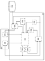
실시간 모델 식별은 등가 회로를 이용하는 실시간 모델 파라미터 추정을 포함한다. 도 13a는 예시적인 배터리(예컨대, 배터리(105))의 등가 회로이다. 배터리가 비동작 상태일 때, V0(s[k])는 배터리의 OCV 이다. 이러한 OCV는 배터리의 SOC에 고유하게 의존한다(s[k]∈[0 1]). 배터리가 활성상태일 때, 예를 들어 전류 활동이 있을 때, 배터리의 동작은 히스테리시스 컴포넌트(h[k]), 직렬 저항(R0) 및 각각 직렬로 연결된 2개의 병렬 RC 회로, 즉 (R1, C1) 및 (R2, C2)로 이루어진 동적 등가 회로를 통해 표현된다. 이산적인 시간을 [k]를 이용하여 나타낸다.Real-time model identification includes real-time model parameter estimation using an equivalent circuit. 13A is an equivalent circuit of an exemplary battery (e.g., battery 105). When the battery is inactive, V 0 (s [k]) is the OCV of the battery. This OCV is uniquely dependent on the SOC of the battery (s [k] ∈ [0 1]). When the battery is activated, for example, when the current activity, the operation of the battery is the hysteresis component (h [k]), the series resistance (R 0), and each of the two parallel series connected RC circuit, that is, (R 1 , C 1 ) and (R 2 , C 2 ). The discrete time is represented using [k].
도 13a에서, 배터리를 통하는 측정된 전류는 다음과 같다:In Figure 13A, the measured current through the battery is:
![]()
![]()
여기서, i[k]는 배터리를 통하는 실제 전류이고, ni[k]는 전류 측정 노이즈이며, 이러한 전류 측정 노이즈는 평균이 0이라 추정되고 σI의 표준 편차(s.d.)를 갖는다. 배터리 양단의 측정된 전압은 다음과 같다:Here, i [k] is the actual current through the battery, n i [k] is the current measurement noise, and this current measurement noise is estimated to be 0 on average and has a standard deviation sd of σ I. The measured voltages across the battery are:
![]()
![]()
여기서, v[k]는 배터리 양단의 실제 전압이고, nv[k]는 전압 측정 노이즈이며, 이러한 전압 측정 노이즈는 평균이 0이고, σV의 표준 편차를 갖는다고 가정한다. It is assumed that v [k] is the actual voltage across the battery, n v [k] is the voltage measurement noise, and this voltage measurement noise has an average of zero and a standard deviation of σ V.
내부 컴포넌트(R0, R1, R2)에 걸친 배터리의 전압 강하와 h[k]는 다음의 형태로 나타낸다:The voltage drop and h [k] of the battery across the internal components (R 0 , R 1 , R 2 ) are given by:
![]()
![]()
여기서 저항기 R1 및 R2를 통하는 전류는 다음의 형태로 나타낼 수 있다:Here the current through resistors R 1 and R 2 can be expressed in the following form:
![]()
![]()
![]()
![]()
여기서,here,
![]()
![]()
![]()
![]()
Δ는 샘플링 간격이다.Δ is the sampling interval.
i[k]를 측정된 전류 zi[k]로 치환하면, 수학식(11) 및 수학식(12)의 전류는 다음과 같이 나타낼 수 있다:By replacing i [k] with the measured current z i [k], the currents in equations (11) and (12) can be expressed as:
![]()
![]()
![]()
![]()
이제, 수학식(8) 및 수학식(10)은 z-도메인에서 다음과 같이 나타낼 수 있다:Now, equations (8) and (10) can be expressed in the z-domain as:
![]()
![]()
다음으로, 수학식(15)는 z-도메인에서 다음과 같이 나타낼 수 있다:Next, equation (15) can be expressed in the z-domain as: < RTI ID = 0.0 >
![]()
![]()
그 결과,As a result,
![]()
![]()
이고, 마찬가지로 수학식(16)에 대해,, And for Equation (16) as well,
![]()
![]()
이 된다..
수학식(17)에 수학식(19) 및 수학식(20)을 치환하면:Substituting Equations (19) and (20) into Equation (17):

이 된다..
수학식(21)을 재배열하여 시간 도메인으로 다시 변환하면:If we re-arrange equation (21) and convert it back to the time domain:
![]()
![]()
여기서,here,

이다.to be.
이제, 수학식(22)를 다음의 형태로 다시 표현할 수 있다:Now, equation (22) can be rewritten as: < RTI ID = 0.0 >
![]()
![]()
여기서, 관측 모델 a[k]T 및 모델 파라미터 벡터 b는 다음의 수학식으로 주어진다:Here, the observation model a [k] T and the model parameter vector b are given by the following equations:
![]()
![]()
![]()
![]()
여기서, 4라는 첨자는 도 13a-13b에 도시된 4개의 모델 중 모델 4에 대응하는 상기 모델을 나타낸다.Here, the suffix "4" indicates the model corresponding to the
수학식(30)에서 전압 강하 관측의 노이즈는 다음으로 표현된다:The noise in the voltage drop observation in equation (30) is expressed as: < RTI ID = 0.0 >
![]()
![]()
이는 다음의 수학식으로 주어지는 자기 상관을 갖는다:It has autocorrelation given by the following equation:

히스테리시스 컴포넌트는 길이 Lb의 시간 인터벌의 배치 동안에 상수라고 가정되며, 예를 들면 다음과 같다:The hysteresis component is assumed to be a constant during the placement of the time interval of length L b , for example:
![]()
![]()
이제, 배터리 동작의 4개의 상이한 "모드" 및 이러한 모드에 부합하는 적절한 배터리 등가 모델에 대해 기술할 수 있다.Now, four different "modes" of battery operation and an appropriate battery equivalence model corresponding to these modes can be described.
a. 모드 1 - 낮은 부하 또는 비동작 상태: 배터리가 단지 낮은 부하 상태이고, 그 후 충전되고 그리고 나서 비동작 상태인 경우, 히스테리시스 컴포넌트는 무시할 만큼 작을 것이다. 이러한 모드의 예로서, 완전히 충전된 후, 다음 충전시까지 매우 적은 전화 통화의 가능성을 제외하고는 대부분의 시간 동안 핑(ping) 테스트를 하는 셀룰러 폰이 있을 것이다. 단일한 저항기(도 13d 참조)가 이러한 모드에 잘 맞는다. a. Mode 1 - Low load or non-operating state: If the battery is only in a low load state, then charged and then inactive, the hysteresis component will be negligible. As an example of this mode, there will be a cellular phone that, after being fully charged, pings for most of the time, except for the possibility of very few phone calls until the next charging. A single resistor (see Figure 13d) fits this mode well.
b. 모드 2 - 일정한 전류 동작: 배터리를 통하는 전류가 일정한 경우, RC 회로의 커패시터는 완전히 충전된다. 그러므로, 파라미터 추정의 측면에서, 결과적인 회로는 단일한 저항기와 히스테리시스/바이어스 컴포넌트로 간주될 수 있다(도 13c 참조). 배터리의 일정한 전류 충전은 이러한 모드에 대한 좋은 예이다.b. Mode 2 - Constant Current Operation: When the current through the battery is constant, the capacitor of the RC circuit is fully charged. Therefore, in terms of parameter estimation, the resulting circuit can be regarded as a single resistor and a hysteresis / bias component (see FIG. 13C). Constant current charging of the battery is a good example of this mode.
c. 모드 3 - 동적 부하: 배터리가 이러한 모드에 있는 경우, 상이한 양의 상당한 부하가 존재한다. 예를 들면, 전화 통화, 웹 브라우징, 비디오 클립 등을 위해 정기적으로 사용되는 스마트 폰이 있다. 도 13b에 도시된 배터리 등가물이 이러한 시나리오에 잘 맞는다. c. Mode 3 - Dynamic Load: When the battery is in this mode, there is a significant amount of significant load. For example, there are smartphones that are regularly used for phone calls, web browsing, video clips, and so on. The battery equivalents shown in FIG. 13B fit this scenario well.
d. 모드 4 - 과부하 및 변화하는 사용량: 모바일 폰의 경우, 과부하 및 변화하는 사용량에는 장기적인 비디오 재생, 멀티미디어 및 게임 애플리케이션 등이 포함된다. 도 13a가 이러한 시나리오에 잘 맞는다. d. Mode 4 - Overload and changing usage: For mobile phones, overload and changing usage include long-term video playback, multimedia and gaming applications. Figure 13a fits this scenario.
동적 등가 회로의 상이한 모델 복잡도는 단지 [k]T를 변화시킴으로써 표현될 수 있다는 점에 주목해야 한다. 각각의 모델에 대한 [k]T의 정의를 이하에서 볼 수 있다. 각각의 상기 모델 복잡도에 대하여, 노이즈 항 nD[k]는 다음과 같이 ![]()
![]()
![]()
![]()


여기서, here,
![]()
![]()
![]()
![]()
![]()
![]()
이다.to be.
다음의 논의는 시불변 동적 모델 파라미터의 최소자승 추정에 관한 것이다. 시간 k에서의 실제 SOC는 다음으로 표현된다:The following discussion relates to least squares estimation of time-invariant dynamic model parameters. The actual SOC at time k is expressed as:
![]()
![]()
발전된 SOC 트랙킹 알고리즘이 이용되어 xS[k]의 업데이트된 추정치, ![]()
![]()
![]()
![]()
여기서, ![]()
![]()

OCV 파라미터 ![]()
![]()
![]()
![]()
여기서, κ는 배치 번호이고,Here, κ is a batch number,
![]()
![]()
![]()
![]()
이다.to be.
그리고, 노이즈 ![]()
![]()
![]()
![]()
여기서, ![]()
![]()
![]()
![]()
![]()
![]()
LS 추정량의 공분산 행렬은 다음으로 주어진다:The covariance matrix of the LS estimator is given by:
![]()
![]()
새로운 측정 배치가 획득되는 경우, LS 추정치는 수학식(50) 내지 수학식(51)을 반복함으로써 재귀적으로 업데이트될 수 있다:If a new measurement arrangement is obtained, the LS estimate can be recursively updated by repeating equations (50) to (51): < EMI ID =
![]()
![]()
![]()
![]()
여기서, λ는 망각(페이딩 메모리) 지수이고, (·)T는 전치 행렬을 나타내며, (·)-1는 역행렬을 나타내고, ![]()
![]()
![]()
![]()
![]()
![]()
![]()
![]()
a. 다음의 근사화가 이루어질 수 있다:a. The following approximations can be made:
![]()
![]()
b. 전류 공분산 행렬을 구성하기 위해 이전의 추정치를 이용하고, 예를 들면 다음 수학식을 이용한다:b. The previous estimate is used to construct the current covariance matrix, for example using the following equation: < RTI ID = 0.0 >
![]()
![]()
다음의 논의는 시변 동적 모델 파라미터의 최소 평균 제곱 오차(MMSE) 추정에 관한 것이다. 동적 모델 파라미터가 다음의 완 변동 위너(Wiener) 프로세스를 거치는 확률 변수라고 가정한다:The following discussion relates to the minimum mean square error (MMSE) estimation of time varying dynamic model parameters. It is assumed that the dynamic model parameters are random variables that go through the following Wiener process:
![]()
![]()
여기서, ![]()
![]()
![]()
![]()
![]()
![]()
후속하는 논의는 관련 개방 회로 전압(OCV) 파라미터 추정에 관련된다. SOC 추정은 개방 회로 전압(OCV) 및 배터리의 SOC 간의 고유하고 안정한 관련성을 활용할 수도 있으며 및 허용 측정된 OCV에 대한 SOC의 계산을 가능하게 한다. 그러나, 배터리가 휴식(rest) 상태에 있는 경우에만 OCV를 직접적으로 측정하는 것도 가능하다. 배터리가 사용 중일 때, 배터리 전압 및 전류 사이의 동적 관련성이 파라미터 및 상태 추정 접근법을 통해 고려되어야 한다. 전하 추정 접근법의 OCV-SOC 기초 상태는 (1) 배터리의 동적 전기적 등가 모델; 및 (2) 측정된 전압 및 전류의 오류와 연관된 오류를 포함한다. 수학식 (43)의 OCV-SOC 특성화(characterization)의 파라미터는 샘플 배터리에 대한 OCV 특성화 데이터를 다음과 같이 수집함으로써 추정될 수 있다:The following discussion relates to the associated open circuit voltage (OCV) parameter estimation. The SOC estimate may exploit the inherent and stable association between the open-circuit voltage (OCV) and the battery's SOC and enables calculation of the SOC for the allowed measured OCV. However, it is also possible to directly measure the OCV only when the battery is at rest. When the battery is in use, the dynamic relationship between battery voltage and current should be taken into account through the parameter and state estimation approach. The OCV-SOC fundamentals of the charge estimation approach are: (1) a dynamic electrical equivalent model of the battery; And (2) errors associated with errors in the measured voltage and current. The parameter of the OCV-SOC characterization of equation (43) can be estimated by collecting the OCV characterization data for the sample battery as follows:
a. 완전히 충전된, 완전히 휴식된(rested) 배터리로부터 시작한다a. Start with a fully charged, fully rested battery
b. 이것의 개방 회로 전압 ![]()
![]()
c. k=1로 설정한다c. k = 1
d. ![]()
![]()
e. k=k+1로 설정한다e. k = k + 1
f. 배터리가 완전히 방전될 때까지 일정한 전류 i[k]의 매우 적은 양(통상적으로, C/30 또는 C/40, 여기에서 C는 Ah 단위의 배터리의 용량)을 사용하여 배터리를 연속적으로 방전한다. 완전히 방전되면, 그 배터리를 놓아두고 그 이후에 배터리가 풀이 될 때까지 충전한다. 그리고 f. The battery is continuously discharged using a very small amount of constant current i [k] (typically C / 30 or C / 40, where C is the capacity of the battery in Ah) until the battery is fully discharged. When fully discharged, the battery is released and then charged until the battery is discharged. And
1. 매 Δ 초마다 배터리 단자 전압 ![]()
![]()
2. ![]()
![]()
g. ![]()
g. ![]()
이제, OCV 모델(43)이 모든 측정 v[k]에 대하여 후속하는 설명에서 벡터 포맷으로 표현될 수 있다:
Now, the OCV model 43 can be represented in vector format in the following description for all measurements v [k]:
![]()
![]()
여기에서, From here,
![]()
![]()
![]()
![]()
![]()
![]()
이다.to be.
그리고 s[k]=SOC[k]로 두면, And s [k] = SOC [k]
![]()
![]()
이다.to be.
이제, OCV 파라미터의 최소자승 추정 배터리 내부 저항 ![]()
Now, the least square estimated battery internal resistance of the OCV parameter ![]()
![]()
![]()
후속하는 논의는 4 개의 예시적인 등가 회로 모델에 관련된다.The following discussion relates to four exemplary equivalent circuit models.
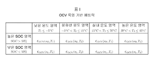
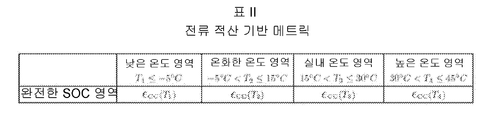
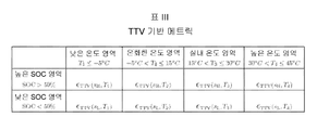
표 1 에 도시된 4 개의 등가 회로 모델의 각각의 회로 성분 양단의 전압은 다음 형식으로 쓰여질 수 있다: The voltage across each circuit component of the four equivalent circuit models shown in Table 1 can be written in the following format:
![]()
![]()
여기에서,From here,


모델 3에 대하여: For Model 3:
![]()
![]()
![]()
![]()
이다.to be.
그리고, 모델 4에 대하여:And for Model 4:
![]()
![]()
![]()
![]()
![]()
![]()
![]()
![]()
![]()
![]()
이다.to be.
다음은 노이즈 상관의 유도에 관련된다. 이러한 섹션에서, ![]()
![]()
![]()
![]()
![]()
![]()

![]()
![]()
![]()
![]()

![]()
![]()

이제, 위의 내용은 각각의 모델에 대하여 다음과 같이 표현될 수 있다:Now, the above can be expressed for each model as:


이러한 논의는 실시간 용량 추정과도 연속되며, 이것은 다음의 표기법을 사용한다.This discussion continues with real-time capacity estimates, which use the following notation.
![]()
![]()
![]()
![]()
![]()
![]()
![]()
![]()
![]()
![]()
![]()
![]()
![]()
![]()
![]()
![]()
![]()
![]()
![]()
![]()
![]()
![]()
![]()
![]()
![]()
![]()
![]()
![]()
![]()
![]()
![]()
![]()
![]()
![]()
![]()
![]()
![]()
![]()
![]()
![]()
![]()
![]()
![]()
![]()
![]()
![]()
![]()
![]()
![]()
![]()
![]()
![]()
![]()
![]()
![]()
![]()
![]()
![]()
![]()
![]()
![]()
![]()
![]()
![]()
![]()
![]()
![]()
![]()
![]()
![]()
![]()
![]()
![]()
![]()
![]()
![]()
![]()
![]()
![]()
![]()
![]()
![]()
![]()
![]()
![]()
![]()
![]()
![]()
![]()
![]()
![]()
![]()
![]()
![]()
![]()
![]()
다음과 같이 정의된 배터리의 충전량(SOC):Charge amount (SOC) of the battery defined as follows:
![]()
![]()
수학식 (78)은 배터리 상태에 대한 정보를 제공한다. SOC 및 배터리 용량의 지식은 배터리의 셧다운 시간(time to shut down; TTS) 또는 완충 시간(time to fully charge; TTF)을 측정하는데 사용된다. 배터리 용량은 통상적으로 온도에 따라 변동하며 이것은 사용 패턴 및 사용 기간에 따라 줄어든다. 배터리 용량의 정확한 트래킹은 배터리 잔량 검량(gauging)의 임계 원소이다.Equation (78) provides information about the battery condition. The knowledge of SOC and battery capacity is used to measure the time to shut down (TTS) or time to fully charge (TTF) of the battery. Battery capacity typically varies with temperature, which decreases with usage pattern and usage time. Accurate tracking of battery capacity is a critical element of battery gauging.
이러한 예시적 구현형태에서, 온라인 용량 추정은 다음에 기초할 수 있다:In this exemplary implementation, the online capacity estimate may be based on:
a. 정확한 가중치의 유도에 따른 용량의 가중된 재귀 최소자승(RLS) 추정. 온라인 용량 추정에 대한 가중된 RLS 접근법은 업데이트된 SOC 트래킹의 시간에 대한 분산 및 공분산 및 전류 측정 오류 표준 편차에 기초하여 가중치에 대한 수학식을 유도하는 것을 포함한다.a. Weighted recursive least squares (RLS) estimation of capacity with induction of exact weights. The weighted RLS approach to on-line capacity estimation involves deriving an equation for the weight based on variance and covariance and current measurement error standard deviation for the time of updated SOC tracking.
b. 배터리 용량의 실시간 트래킹에 대한 TLS 접근법. TLS 접근법은 용량 추정에 대한 닫힌 수식을 제공한다. 이러한 접근법은 배터리 용량의 변화를 연속적으로 트래킹하기 위하여 사용될 수 있다.b. TLS approach to real-time tracking of battery capacity. The TLS approach provides closed formulas for capacity estimation. This approach can be used to continuously track changes in battery capacity.
c. 휴식된 배터리의 OCV 룩업에 기초한 적응적 용량 추정. OCV 룩업 기초 SOC 추정에 대한 배터리 레스팅 실례에 의한 배터리 용량의 온라인 트래킹에 대한 TLS 접근법.c. Adaptive capacity estimation based on OCV lookup of a resting battery. A TLS Approach to Online Tracking of Battery Capacity by Battery Resting Example for OCV Lookup Based SOC Estimation.
d. 상이한 접근법을 통하여 획득된 용량 추정들의 융합.d. Convergence of capacity estimates obtained through different approaches.
후속하는 논의는 배터리 용량 추정 및 융합에 관련된다. 배터리의 순시 충전량(SOC)은 다음 프로세스 모델로서 쓰여질 수 있는데, 이것은 다음과 같이 측정된 전류에 대한 전류 적산 방정식이라고도 알려진다: The following discussion relates to battery capacity estimation and convergence. The instantaneous charge (SOC) of the battery can be written as the following process model, also known as the current integration equation for the current measured as follows:
![]()
![]()
여기에서 ![]()
![]()
![]()
![]()
![]()
![]()
![]()
![]()
![]()
![]()
이다.to be.
이것은 표준 편차(s.d.) ![]()
![]()
![]()
![]()
![]()
![]()
그리고 표준편차And standard deviation
![]()
![]()
가 있는 제로 평균이고,Lt; / RTI >
여기에서 전류 적산 계수는 Here, the current integration coefficient is
![]()
![]()
이다.to be.
여기에서, ![]()
![]()
![]()
![]()
이고ego
![]()
![]()
후속하는 논의는 재귀 최소자승(RLS)을 사용한 온라인 배터리 용량 추정에 관련된다. 추정 SOC는 전압 및 전류 측정 모두에 기초할 수 있다. 두 개의 연속적 SOC 값 ![]()
![]()
![]()
![]()

여기에서 추정 오류 ![]()
![]()
![]()
![]()
![]()
![]()
![]()
![]()
![]()
![]()
인데, 여기에서 ![]()
![]()
![]()
![]()
![]()
![]()
![]()
![]()
수학식 (87)에서 수학식 (84) 및 (85)를 대체하면:Substituting Equations (84) and (85) in Equation (87):
![]()
![]()
인데, 여기에서,Here,
![]()
![]()
이고,ego,
그리고, And,
![]()
![]()
에 의하여 주어진 차동 오류는The differential error given by
분산:Dispersion:
![]()
![]()
이 있는 제로 평균이며,Is zero mean,
여기에서 ![]()
![]()
![]()
![]()
![]()
![]()
여기에서, From here,
![]()
![]()
![]()
![]()
![]()
![]()

![]()
![]()
이고, ![]()
![]()
![]()
![]()
이것은 ![]()
![]()
![]()
![]()
이제, 반전 배터리 용량의 LS 추정은 다음에 의하여 주어지고:Now, the LS estimate of the reversed battery capacity is given by: < RTI ID = 0.0 >
![]()
![]()
그리고 LS 반전 용량 추정의 분산은: The variance of the LS inversion capacity estimate is:
![]()
![]()
이다.to be.
![]()
![]()
![]()
![]()
![]()
![]()
여기에서 ![]()
![]()
![]()
![]()
![]()
![]()
![]()
![]()
![]()
![]()
![]()
![]()
![]()
![]()
후속하는 논의는 적응적 전 최소자승(TLS)을 사용한 온라인 배터리 용량 추정에 관련된다. 이 섹션에서, 온라인 용량 추정 방법은 수학식 (92) 내의 ![]()
![]()
![]()
![]()
![]()
![]()
증강된 관측 행렬과 연관된 정보 행렬은:The information matrix associated with the enhanced observation matrix is:
![]()
![]()
이다.to be.
![]()
![]()
![]()
![]()
여기에서, From here,
![]()
![]()
![]()
![]()
![]()
![]()
![]()
![]()
![]()
![]()
![]()
![]()
![]()
![]()
![]()
![]()
그러면 반전 배터리 용량의 TLS 추정은 ![]()
![]()
![]()
![]()
에 의하여 주어지는데,Which,
여기에서 ![]()
![]()
![]()
![]()
![]()
![]()
![]()
![]()
더 부드러운 추정을 위하여, 수학식 (103)의 정보 행렬은 다음과 같이 페이딩 메모리로써 업데이트될 수 있다:For smoother estimation, the information matrix of equation (103) may be updated with fading memory as follows:
![]()
![]()
이제, 수학식 [85]에 기초하여, TLS 추정 오류 공분산은(근사적으로):
Now, based on equation [85], the TLS estimation error covariance (approximate) is:
![]()
![]()
이다.to be.
여기에서 ![]()
![]()
![]()
![]()
![]()
![]()
![]()
![]()
![]()
![]()
이다.to be.
후속하는 논의는 개방 회로 전압(OCV) 기초 배터리 용량 추정에 관련된다. 주어진 휴식된 전압 ![]()
![]()
![]()
![]()
![]()
![]()
![]()
![]()
![]()
![]()

여기에서 계수 ![]()
![]()
![]()
![]()
![]()
![]()
![]()
![]()
수학식 (109)의 반전을 연산함에 의한 OCV-SOC 특성화를 사용하여 연산될 수 있다. 비선형 함수의 반전을 연산하기 위한 수 개의 방법, 예컨대 뉴튼의 방법 및 이진 탐색이 존재한다. 이것은 OCV 룩업 기초 SOC 추정이라고 지칭될 수도 있다. 수학식 (110)의 SOC 추정은 다음과 같이 히스테리시스 전압에 의하여 오류가 생기는데:Can be computed using OCV-SOC characterization by computing the inversion of equation (109). There are several methods for computing the inversion of the nonlinear function, e.g., Newton's method and binary search. This may be referred to as OCV lookup based SOC estimation. The SOC estimation of Equation (110) results in an error due to the hysteresis voltage as follows:
![]()
![]()
여기에서 OCV 룩업 오류 ![]()
![]()
![]()
![]()
![]()
![]()
![]()
![]()
![]()
![]()
![]()
![]()
![]()
![]()
......
![]()
![]()
수학식 (112) 내지 (114)를 양단에 추가하면, 다음이 얻어지는데: By adding equations (112) to (114) to both ends, the following is obtained:

여기에서, From here,
![]()
![]()
![]()
![]()
배터리가 시간 ![]()
![]()
![]()
![]()
![]()
![]()
여기서here

![]()
![]()
![]()
![]()
이다.to be.
OCV 룩업 오류 ![]()
![]()
![]()
![]()
![]()
![]()
![]()
![]()
![]()
![]()
![]()
![]()
![]()
![]()
여기에서,From here,
![]()
![]()
![]()
![]()
![]()
![]()
이다.to be.
이제, 수학식 (120)이 ![]()
![]()
![]()
![]()
![]()
![]()
![]()
![]()
![]()
![]()
![]()
![]()
![]()
![]()
![]()
![]()
![]()
![]()
![]()
![]()
![]()
![]()
![]()
![]()
![]()
![]()
다음은 융합을 통한 용량 추정에 관련된다. 이 섹션에서, 용량의 TLS 추정들을 융합하기 위한 예시적인 구현예가 설명된다. 이 섹션에서의 유도는 TLS 기초 용량 추정에 대하여 개발된다. 유도는 RLS 기초 용량 추정을 융합시키기 위해서도 역시 적용될 수 있다.The following are related to capacity estimation through fusion. In this section, an exemplary implementation for fusing TLS estimates of capacity is described. The derivations in this section are developed for TLS baseline capacity estimates. Induction can also be applied to fuse RLS baseline capacity estimates.
온라인 용량 추정 ![]()
![]()
![]()
![]()
![]()
![]()
![]()
![]()
![]()
![]()
![]()
![]()
![]()
![]()
![]()
![]()
우선, 반전 용량에 대한 추정, 예를 들어, 용량 추정 ![]()
![]()
![]()
![]()
![]()
![]()
![]()
![]()
![]()
![]()
![]()
![]()
![]()
![]()
여기에서 ![]()
![]()
![]()
![]()
![]()
![]()
![]()
![]()
![]()
![]()
![]()
![]()
여기에서 ![]()
![]()
![]()
![]()
![]()
![]()
![]()
![]()
![]()
![]()
여기에서, From here,
![]()
![]()
이고,ego,
![]()
![]()
![]()
![]()
![]()
![]()
![]()
![]()
이제, 새로운 측정 ![]()
![]()
![]()
![]()
![]()
![]()

여기에서 ![]()
![]()
![]()
![]()
![]()
![]()
위의 융합 접근법은 RLS 기초 용량 추정들을 융합하기 위하여 유사하게 사용될 수 있다.The above fusion approach can be similarly used to fuse RLS based capacity estimates.
다음은 용량 추정 오류 공분산의 유도에 관련된다. 이 섹션에서, 수학식 (90)에서의 차동 오류의 공분산이 유도된다. 편의를 위하여 차동 오류 (90)는 다음과 같이 쓰여진다 The following is related to the derivation of the capacity estimation error covariance. In this section, the covariance of the differential error in equation (90) is derived. For the sake of convenience, the differential error 90 is written as
![]()
![]()
목적은 분산을 연산하는 것이다:The goal is to compute the variance:
![]()
![]()
프로세스 수학식 (79)을 다음 형태로 쓰면: Using the process equation (79) in the form:
![]()
![]()
![]()
![]()
여기에서 ![]()
![]()
![]()
![]()
![]()
![]()
![]()
![]()
![]()
![]()
이며And
이것은 다음 형태로 재정렬될 수 있다:It can be reordered in the following form:
![]()
![]()
그러므로,therefore,
![]()
![]()
인데, 여기에서, Here,
![]()
![]()
이하 위의 유도를 확증하는 대안적 또는 제 2 접근법이 설명된다. 수학식 (132)를 확장하면:An alternative or second approach to verify the above derivations is described below. By extending equation (132): < RTI ID = 0.0 >
![]()
![]()
![]()
![]()
인데, 여기에서, Here,


이다.to be.
다음은 전최소자승(TLS) 용량 추정의 닫힌 형태 유도이다. ![]()
![]()

![]()
![]()
A의 고유값은 다음을 만족하는데 The eigenvalues of A satisfy
![]()
![]()

이것은 다음과 같이 단순화되고, This is simplified as follows,
![]()
![]()
여기에서 ![]()
![]()
![]()
![]()
![]()
![]()
![]()
![]()
여기서, here,

이고,ego,
예를 들어: E.g:
![]()
![]()
![]()
![]()
이며, Lt;

이다.to be.
다음은 반전 용량 추정의 변환에 관련된다. 예시적인 구현형태는 용량 추정치 및 추정 오류 분산을 반전 추정 및 반전 추정 오류 분산에 기초하여 획득하는 접근 방법을 포함한다. 반전 용량 추정 및 오류 분산에 대하여, 심플 변수(simple variables)를 지정하면, 예를 들어, The following relates to the conversion of inversion capacity estimates. An exemplary implementation includes an approach for obtaining a capacity estimate and an estimated error variance based on an inverse estimate and an inverse estimate error variance. When simple variables are specified for inverse capacitance estimation and error distribution, for example,
![]()
![]()
![]()
![]()
![]()
![]()
이다.to be.
다음을 정의한다:Define the following:
![]()
![]()
우리의 목적은 ![]()
![]()
![]()
![]()
다음은 y의 기대값을 결정하는 것에 관련된다 2차 테일러 급수 근사는 다음에 의하여 주어진다The following is related to determining the expected value of y. The second Taylor series approximation is given by
![]()
![]()
![]()
![]()

다음은 y의 기대값의 분산을 결정하는 것에 관련된다. ![]()
![]()
![]()
![]()
![]()
![]()
이 된다..
![]()
![]()
![]()
![]()
이제, 용량 추정의 기대값 및 이것의 추정 오류 분산은 다음에 의하여 주어진다Now, the expected value of the capacity estimate and its estimated error variance are given by
![]()
![]()
![]()
![]()
본 개시시물은 충전량(SOC) 트래킹으로 계속되는데, 이것은 다음의 명명법을 참조할 수도 있다.The water at the present disclosure continues with a charge amount (SOC) tracking, which may refer to the following nomenclature.
![]()
![]()
![]()
![]()
BFG 배터리 잔량 게이지 BFG battery remaining gauge
![]()
![]()
![]()
![]()
![]()
![]()
![]()
![]()
![]()
![]()
![]()
![]()
![]()
![]()
![]()
![]()
![]()
![]()
![]()
![]()
![]()
![]()
![]()
![]()
![]()
![]()
![]()
![]()
![]()
![]()
![]()
![]()
![]()
![]()
![]()
![]()
![]()
![]()
![]()
![]()
![]()
![]()
![]()
![]()
![]()
![]()
![]()
![]()
OCV 개방 회로 전압 OCV open circuit voltage
![]()
![]()
![]()
![]()
![]()
![]()
![]()
![]()
![]()
![]()
![]()
![]()
![]()
![]()
![]()
![]()
SOC 충전량 SOC charge amount
![]()
![]()
![]()
![]()
![]()
![]()
![]()
![]()
![]()
![]()
![]()
![]()
![]()
![]()
![]()
![]()
![]()
![]()
![]()
![]()
![]()
![]()
![]()
![]()
![]()
![]()
![]()
![]()
![]()
![]()
![]()
![]()
![]()
![]()
![]()
![]()
![]()
![]()
![]()
![]()
![]()
![]()
![]()
![]()
![]()
![]()
![]()
![]()
이 예의 구현예에서, 전기 화학적 저장 장치(배터리)의 충전량(SOC)은 순시 단자 전압(instantaneous terminal voltage), 부하 전류, 및 온도 측정치에 기초하여 트랙킹된다. SOC 트랙킹 알고리즘은 전술한 배터리 용량 추정치 및 모델 파라미터 추정치에 대한 지식(knowledge)을 이용한다. 일례의 SOC 트랙킹은 히스테리시스를 개방 회로 전압(OCV)에서의 오차로서 모델링하고, 이 오차를 보상하기 위해 파라미터 추정 및 SOC 트랙킹 기술의 조합을 채용한다. 이것은 SOC 및 부하 전류를 함수로 하는 히스테리시스의 오프라인 모델링에 대한 필요성을 제거한다. 이 예의 모델은 배터리 등가 모델의 복잡도의 레벨에 상관없이 추가의 변수가 트랙킹될 필요가 없는 곳에서는 SOC 트랙킹을 위한 감소된 차수(예컨대, 단일 상태) 필터링을 발생한다. 상관된 노이즈의 존재가 식별되고, 향상된 SOC 트랙킹을 위해 이용된다. 종래의 "하나의 모델이 모두에 들어맞음(one model fits all)" 전략으로부터의 편차로서, 4개의 고유 모드의 전형적인 배터리 동작을 표현하고, 적합한 모델에 기초하여 끊김없는(seamless) SOC 트랙킹을 위해 프레임워크를 전개하는, 배터리의 4개의 상이한 등가 모델이 식별된다.In an implementation of this example, the charge amount (SOC) of the electrochemical storage device (battery) is tracked based on the instantaneous terminal voltage, load current, and temperature measurements. The SOC tracking algorithm utilizes knowledge of the battery capacity estimates and model parameter estimates described above. An exemplary SOC tracking model hysteresis as an error in open circuit voltage (OCV) and employs a combination of parameter estimation and SOC tracking techniques to compensate for this error. This eliminates the need for off-line modeling of hysteresis as a function of SOC and load current. The model of this example generates reduced order (e.g., single state) filtering for SOC tracking where no additional variables need to be tracked, regardless of the level of complexity of the battery equivalent model. The presence of correlated noise is identified and used for improved SOC tracking. As a deviation from the conventional " one model fits all "strategy, it represents the typical battery operation of four eigenmodes, and for seamless SOC tracking based on the appropriate model Four different equivalent models of the battery, which evolve the framework, are identified.
다른 가외의(redundant)(잡음성의(nuisance)) 정량(quantity)과 함께 SOC의 합동(재귀적) 추정을 포함하는 전형적인 감소된 차수 상태 필터링 방법은, 많은 자원이 필요한 행렬 연산(computationally expensive matrix operation)을 수반하고, SOC 추정의 정확도를 감소시킨다. 이 예의 구현예에서, 상태 공간 치수(state space dimension)를 증가시키지 않아 SOC 정확도를 더 좋게 하고 컴퓨터 처리 복잡도를 감소시키는 감소된 차수 필터링이 활용된다. 히스테리시스 모델링에 대한 필요성은 히스테리시스를 OCV에서의 오차로서 모델링함으로써 제거되며, 온라인 필터링 방법은 SOC를 (정확한 값으로) 조정함으로써 갭(gap)을 채우려고 지속적으로 시도한다. 그러므로, 히스테리시스는 시간-변화 바이어스(time-varying bias)로서 모델링된다. 노이즈 화이트닝 과정(noise whitening procedure)이 적용되며, SOC 트랙킹 알고리즘이 최소 평균 자승 오차(minimum mean square error)의 의미에서 최상의 가능한 결과를 산출하도록 하기 위해 수정된 상태-공간 모델이 얻어진다. SOC는 배터리의 상이한 "모드"를 이용하여 추적된다. 매우 가벼운 부하 또는 휴식(rest) 상태, 일정 전류 작동 또는 낮은 빈도의 부하(low frequency loading), 동적 부하, 및 무거운 부하를 반영하기 위해 적어도 4개의 상이한 배터리 등가 모델이 이용된다. 이들 모드를 역시 최상으로 정합시키기 위해 4개의 (다소) 상이한 동적 등가 모델이 식별된다. 제안된 감소된 차수 필터링 방법은 배터리 동작에서의 모드 변화에 상관없이 끊김없는 SOC 트랙킹을 보장한다.A typical reduced order state filtering method involving joint (recursive) estimation of SOC with other redundant (nuisance) quantities is computationally expensive matrix operation ), And reduces the accuracy of SOC estimation. In an implementation of this example, reduced order filtering is utilized that does not increase the state space dimension, thereby improving SOC accuracy and reducing computer processing complexity. The need for hysteresis modeling is eliminated by modeling the hysteresis as an error in the OCV, and the on-line filtering method continually tries to fill the gap by adjusting the SOC (to the correct value). Hence, the hysteresis is modeled as a time-varying bias. A noise whitening procedure is applied and a modified state-space model is obtained to allow the SOC tracking algorithm to produce the best possible outcome in the sense of a minimum mean square error. The SOC is tracked using different "modes" of the battery. At least four different battery equivalent models are used to reflect very light loads or rest states, constant current operation or low frequency loading, dynamic loads, and heavy loads. Four (somewhat) different dynamic equivalent models are identified to best match these modes as well. The proposed reduced order filtering method guarantees seamless SOC tracking regardless of mode changes in battery operation.
이하의 논의는 일례의 시스템 모델에 관한 것이다. 본 명세서에서 고려되는 배터리 등가 회로 모델이 도 13a에 도시되어 있다. 배터리가 휴식 상태에 있을 때, V0(s[k])는 배터리의 OCV이다. OCV는 배터리의 SOC인 s[k]에 고유하게 좌우된다. 배터리가 활성 상태일 때, 예컨대 전류 활동(current activity)이 있을 때, 배터리의 동작은 히스테리시스 콤포넌트 h[k], 직렬 저항 R0, 및 직렬로 접속된 2개의 병렬 RC 회로 (R1, C1) 및 (R2, C2)로 이루어진 동적 등가 회로를 통해 표현된다. 이산적인 시간(discrete time)은 [k]를 이용하여 나타내진다.The following discussion relates to an exemplary system model. A battery equivalent circuit model considered herein is shown in Figure 13A. When the battery is at rest, V 0 (s [k]) is the OCV of the battery. OCV is uniquely dependent on the battery's SOC, s [k]. When the battery is active, such as when there is a current activity, the operation of the battery is controlled by a hysteresis component h [k], a series resistance R 0 , and two parallel RC circuits R 1 , C 1 ) And (R 2 , C 2 ). The discrete time is expressed using [k].
이 절에서 고려되는 배터리 등가 회로 모델은 도 13a에 도시되어 있다. 배터리 등가 회로의 콤포넌트의 항에서의 단자 전압 v[k]는 다음과 같이 주어진다:The battery equivalent circuit model considered in this section is shown in Figure 13A. The terminal voltage v [k] in terms of the components of the battery equivalent circuit is given by:
![]()
![]()
여기서, V0(s[k])는 시각 t에서의 SOC의 함수 s[k]∈[0,1] 로서 작성된 시각 k에서의 배터리의 개방 회로 전압(볼트)을 나타내며; h[k]는 배터리 전압에서의 히스테리시스를 설명하고; i1[k]와 i2[k]는 각각 저항 R1과 R2를 통과하는 전류이다.Where V 0 (s [k]) represents the open circuit voltage (in volts) of the battery at time k created as a function s [k] ∈ [0,1] of the SOC at time t; h [k] describes the hysteresis at the battery voltage; i 1 [k] and i 2 [k] are the currents passing through resistors R 1 and R 2 , respectively.
SOC를 함수로 하여 OCV를 근사하는 여러 개의 비선형 표현(nonlinear representation)이 있다. 이 예의 구현예에서, SOC의 항에서의 OCV의 표현에 대한 역 다항식-로그-선형 모델(inverse polynomial-log-linear model)은 다음과 같다:There are several nonlinear representations that approximate OCV with SOC as a function. In this example implementation, an inverse polynomial-log-linear model for the representation of OCV in terms of SOC is: < RTI ID = 0.0 >

여기서, k0, k1, k2, k3, k4, k5, k6 및 k7은 OCV-SOC 특성화(characterization)를 통해 오프라인으로 추정될 수 있다. SOC에서의 순시 변화(instantaneous change)가 다음의 형태로 작성될 수 있다(x의 아래 첨자는 상태 콤포넌트를 나타내기 위해 제공됨):Here, k 0 , k 1 , k 2 , k 3 , k 4 , k 5 , k 6 and k 7 can be estimated offline by OCV-SOC characterization. The instantaneous change in the SOC can be written in the following form (the subscript of x is provided to represent the state component):
![]()
![]()
여기서, i[k]는 암페어(Amp)의 단위이며,Here, i [k] is a unit of ampere (Amp)
![]()
![]()
는 Amp-1sec-1 단위의 전류 적산 계수(Coulomb counting coefficient)이며, Cbatt는 암페어 시(Ah) 단위의 배터리의 용량이며, Δ는 초 단위의 샘플링 간격이며, η는 배터리가 예컨대 아래와 같이 충전되고 있는지 아니면 방전되고 있는지의 여부에 좌우되는 상수이다:Is the Coulomb counting coefficient of Amp -1 sec -1 , C batt is the capacity of the battery in Ah (Ah), Δ is the sampling interval in seconds, and η is the battery's capacity It is a constant depending on whether it is being charged or discharged:

수학식(168)이 배터리의 순시 SOC를 산출한다는 것에 유의하여야 한다. SOC를 계산하는 이 기술은 전류 적산 및/또는 "예측된 SOC"로 지칭된다. 전류 적산은 초기 충전량에 대한 지식 및 배터리로부터 전달된 또는 배터리에 전달된 쿨롱(전류; Coulomb)의 양을 설명한 후의 잔여 충전량을 계산하기 위해 배터리 용량에 대한 완전한 지식을 가정(assume)한다. 전류 적산 오차는, (1) 초기 SOC의 지식에서의 불확정성, (2) 배터리 용량의 지식에서의 불확정성, 및 (3) 타이밍 오실레이터 부정확성/드리프트로 인한 시간차에서의 오차 및 측정된 전류에서의 오차의 결과의 측정된 전류에서의 오차를 포함한다.It should be noted that equation (168) yields the instantaneous SOC of the battery. This technique of calculating SOC is referred to as current integration and / or "predicted SOC ". Current integration assumes a complete knowledge of battery capacity to calculate the amount of residual charge after describing the amount of initial charge and the amount of Coulomb delivered to or delivered from the battery. The current integration errors are due to (1) uncertainty in the knowledge of the initial SOC, (2) uncertainty in the knowledge of the battery capacity, and (3) errors in time differences due to timing oscillator inaccuracy / And the error in the measured current of the result.
전류 i[k]가 측정되고, 전류 측정치가 오차에 놓이게 된다. 측정된 전류 zi[k]는 다음과 같이 작성된다:The current i [k] is measured, and the current measurement value is in error. The measured current z i [k] is written as follows:
![]()
![]()
여기서, ni[k]는, 백색의 제로-중간(zero-mean)으로 간주되고, 공지의 표준 편차(S.d.) σi를 갖는 전류 측정 노이즈이다. 상태 수학식(168)은 다음과 같이 i[k]를 zi[k]로 대체함으로써 다시 작성될 수 있다:Here, n i [k] is a current measurement noise which is regarded as a zero-mean of white and has a known standard deviation Sd i . The state equation (168) can be rewritten by replacing i [k] with z i [k] as follows:
![]()
![]()
저항 R1과 R2를 통과하는 전류는 아래의 형태로 작성될 수 있다:The current through resistors R 1 and R 2 can be written as:

여기서, 다음과 같이 된다:Here is the following:


i[k]를 측정된 전류 zi[k]로 대체함으로써, 수학식(172) 및 (173)에서의 전류는 다음과 같이 다시 작성될 수 있다:By replacing i [k] with the measured current z i [k], the currents in equations (172) and (173) can be rewritten as:
![]()
![]()
![]()
![]()
히스테리시스 전압 h[k]은 배터리의 부하 전류 및 SOC의 비선형 함수이다. 히스테리시스 프로세스는 다음과 같이 작성될 수 있다:The hysteresis voltage h [k] is a nonlinear function of the load current and SOC of the battery. The hysteresis process can be written as:

여기서, nh[k]는, 백색의 제로-중간 가우스(zero-mean Gaussian)로 가정되고 표준 편차(S.d.) σh를 갖는 히스테리시스 모델의 프로세스 노이즈이다. 수학식(166)에서의 전압은 측정 정량(measured quantity)이고, 측정 전압 zv[k]는 오차에 놓이게 된다. 측정 전압은 다음과 같이 작성된다:Where n h [k] is the process noise of the hysteresis model with a standard deviation (Sd) σ h , assuming a zero-mean Gaussian of white. And the voltage amount (measured quantity) measured in equation (166), measuring the voltage v z [k] is placed in error. The measured voltage is written as follows:

여기서, nv[k]는, 제로-중간 및 표준 편차(S.d.) σv를 갖는 백색 가우스 노이즈로 가정된다. 이제, 수학식(179)에 수학식(171), (172), (173) 및 (178)을 대입함으로써, 이하의 측정 모델이 구해진다:Here, n v [k] is assumed to be a white Gaussian noise having a zero-median and standard deviation (Sd) σ v . Now, by substituting equations (171), (172), (173) and (178) into equation (179), the following measurement model is obtained:
![]()
![]()
여기서, 다음과 같이 된다:Here is the following:
![]()
![]()
이제, 순시 전압 및 전류 측정치 zv[k] 및 zi[k]이 주어지면, BFG의 오브젝티브(objective)가 배터리의 순시 SOC, xs[k]를 트랙킹할 것이다. 관측 모델(180)에서의 "잡음(nuisance)" 변수 ![]()
![]()
![]()
![]()

를 재귀적으로 추정하기 위해 베이지언 비선형 필터링 기술(Bayesian nonlinear filtering technique)을 적용함으로써 달성될 수 있으며, 이것은 수학식(171) 및 (180)를 포함하는 곳에서는 시각 k까지의 모든 측정치 {[0],[1],[2],…,[k]}가 주어진 것을 전제로 한다. 이것은 확장 칼만 필터(extended Kalman filter, UKF), 언센티드 칼만 필터(unscented Kalman filter, UKF) 또는 파티클 필터(particle filter)와 같은 널리 공지된 비선형 필터링 기술을 적용함으로써 효율적으로 수행될 수 있다. 프로세스 수학식(172), (176), (177) 및 (178)은 아래와 같이 벡터 형태로 작성되거나,Which can be achieved by applying a Bayesian nonlinear filtering technique to recursively estimate all the measurements {k [0, 1, 2, 3, 4, ], [1], [2], ... , [k]} are given. This can be efficiently performed by applying well known nonlinear filtering techniques such as an extended Kalman filter (UKF), an unscented Kalman filter (UKF), or a particle filter. The process mathematical expressions (172), (176), (177), and (178)

또는 아래와 같이 간략하게 작성될 수 있으며,Alternatively, it can be written briefly as follows,
![]()
![]()
여기서, 아래의 수학식
Here, the following equation

은 제로 중간 및 공분산을 갖는 아래의 백색 노이즈 벡터이다:Is the following white noise vector with zero mean and covariance:

이에 대응하여, 측정 수학식(180)은 다음과 같이 작성될 수 있으며,Correspondingly, the measurement equation (180) can be written as follows,
![]()
![]()
여기서,here,
![]()
![]()
이며, nz[k]는 제로 중간 및 다음의 표준 편차를 갖는 노이즈 벡터이다:, And n z [k] is a noise vector with a zero mean and a standard deviation of:
![]()
![]()
이에 부가하여, 상태-공간 표현(183)~(189)는 배터리 용량 Cbatt, 개방 회로 전압 모델 파라미터 K0, K1, K2, K3, K4, K5, K6, K7, 동적 등가 회로 모델 파라미터 R0, R1, C1, R2, C2, 충전 및 방전 효율 ηc, ηd, 프로세스 노이즈 분산 ![]()
![]()
![]()
![]()
모든 모델 파라미터를 추정해야 하는 요건은 SOC 트랙킹 문제를 더욱 큰 도전과제로 만든다. 또한, 온도 변화, 에이징 및 사용 패턴의 결과 및 이들 모델 파라미터의 결과에 의한 배터리 변화의 화학적 특성은 시간이 지남에 따라 변하게 된다. 그러므로, 모델 파라미터는 시간이 지남에 따라 재추정되어야 한다.The requirement to estimate all the model parameters makes the SOC tracking problem a bigger challenge. In addition, the chemical properties of the battery changes due to the results of temperature changes, aging and usage patterns, and as a result of these model parameters, will change over time. Therefore, the model parameters must be re-estimated over time.
일례의 구현예에서, 배터리의 OCV 파라미터 K0, K1,…, K7가 오프라인으로 추정되는 것으로 가정된다. 이들 파라미터를 추정하기 위한 과정이 위에 설명되어 있다. 전압 측정 오차 표준 편차 σv 및 전류 측정 오차 표준 편차 σi는 측정 회로 설계로부터 이용 가능하게 되는 것으로 가정된다. 충전 효율 ηc 및 방전 효율 ηd은 교정을 통해 알게 되는 것으로 가정된다. 그러므로, 오브젝트브는 배터리 용량 Cbatt 및 배터리의 전기적 등가 모델 파라미터 R0, R1, R2, C1 및 C2의 지식을 가정함으로써 온라인 SOC 트랙킹 알고리즘을 개발하는 것이다.In an exemplary implementation, the OCV parameters K 0 , K 1 , ... , It is assumed that K 7 is estimated to be offline. The procedure for estimating these parameters is described above. It is assumed that the voltage measurement error standard deviation σ v and the current measurement error standard deviation σ i become available from the measurement circuit design. It is assumed that the charge efficiency eta c and the discharge efficiency eta d are known through calibration. Therefore, Objective is to develop an on-line SOC tracking algorithm by assuming knowledge of the battery capacity C batt and the electrical equivalent model parameters R 0 , R 1 , R 2 , C 1 and C 2 of the battery.
이하의 설명은 SOC 트랙킹에 관한 것이다. 감소된 차수의 필터링의 오브젝티브는 가외 변수 ![]()
![]()
![]()
![]()
![]()
![]()
여기서,here,
![]()
![]()
는 아래의 표준 편차를 갖는 백색이 되는 프로세스 노이즈이다:Is the white process noise with the following standard deviation:
![]()
![]()
이제, 전압 측정 수학식(180)을 다음과 같이 다시 작성한다:Now, rewrite the voltage measurement equation (180) as follows:
![]()
![]()
여기서,here,
![]()
![]()
이며, 전압 드롭이 아래의 수학식에 의해 제공되며,And a voltage drop is provided by the following equation,
![]()
![]()
여기서, b는 추정될 파라미터 벡터이고, nD[k]는 측정 노이즈이다. 수학식(194)에서의 [k]는 전압 드롭 vD[k-1] 및 vD[k-2]의 항으로 정의된다는 것에 유의하여야 한다. 전압 드롭 관측 모델에 기초하여 파라미터 b를 추정하는 것을 위에서 설명하였다. 추정된 파라미터는 아래와 같이 도 13a에서의 배터리 등가 모델의 파라미터의 항에서 구해진다:Where b is the parameter vector to be estimated and n D [k] is the measured noise. It should be noted that [k] in the equation (194) is defined by the terms of the voltage drops v D [k-1] and v D [k-2]. It has been described above that the parameter b is estimated based on the voltage drop observation model. The estimated parameters are obtained in terms of parameters of the battery equivalent model in Fig. 13A as follows:
![]()
![]()
![]()
![]()
![]()
![]()
![]()
![]()
![]()
![]()
![]()
![]()
측정 노이즈 nD[k]는 제로 중간이고, 아래에 의해 주어진 자동상관(autocorrelation) ![]()
![]()

다음으로, 수학식(193)에서의 파라미터 b를 추정함에 있어서의 중요성을 설명한다. 수학식(193)을 이용하여, 전압 드롭(195)은 다음과 같이 작성될 수 있다:Next, the importance in estimating the parameter b in the equation (193) will be described. Using equation (193), voltage drop 195 can be written as: < RTI ID = 0.0 >
![]()
![]()
전압 드롭 관측이 주어지면, 위의 모델(203)은 b를 선형으로 추정하기 위해 이용될 수 있다. 그러나, 전압 드롭을 관측으로서 얻기 위해서는, SOC의 예측된 값 ![]()
![]()
![]()
![]()
![]()
![]()
아래에서는, 예측된 SOC ![]()
![]()
![]()
![]()
모델 식별을 위해 배터리 단자를 가로지르는 전압 관측(180)을 이용하면, 히스테리시스 xh[k]은 또한 모델링될 필요가 있고, 모델 파라미터가 추정되어야 한다. SOC, 전류, 및 시각의 항에서의 히스테리시스를 위한 모델은 비선형적이며, 아직 전체적으로 이해되지 못하고 있다. 히스테리시스를 모델링하고 추정하려는 시도의 또 다른 단점은 온라인 모델 식별을 거의 불가능하게 만든다는 점이다. 히스테리시스가 SOC의 함수이기 때문에, 모델 식별은 SOC의 전체 범위에 걸쳐있는(spanning) 데이터를 요구한다. 이것은 몇몇 어플리케이션이 배터리를 완충 상태(full)에서부터 완전방전 상태(empty)까지 결코 이용할 수 없을 수도 있으므로 불가능한 경우가 있을 수 있다. 히스테리시스가 또한 전류의 함수이므로, 모델 식별은 다양한 듀레이션 동안 인가된 가능한 부하 전류에 걸쳐있는 사용량 데이터(usage data)를 요구한다. 그러므로, 히스테리시스의 완전한 모델링 및 모델 식별이 실현 가능하지 않게 된다.Using voltage measurements 180 across the battery terminals for model identification, the hysteresis x h [k] also needs to be modeled and the model parameters have to be estimated. The model for hysteresis in terms of SOC, current, and time is nonlinear and not yet fully understood. Another disadvantage of attempting to model and estimate hysteresis is that it makes online model identification almost impossible. Because hysteresis is a function of SOC, model identification requires data spanning the entire range of SOCs. This may not be possible because some applications may never be able to use the battery from full (full) to empty (empty). Since hysteresis is also a function of current, model identification requires usage data that spans the possible load currents applied over various durations. Therefore, complete modeling and model identification of the hysteresis is not feasible.
샘플 배터리를 이용하여 오프라인으로 모델 파라미터를 추정하고 그리고나서 잔량 측정(fuel gauging)에서 이들 파라미터를 이용하는 것은 만족스럽지 않을 수도 있다는 것에 유의하는 것 또한 중요하며, 배터리 파라미터의 몇몇이 사용 패턴에 기초하여 변경되는 것으로 알려져 있다. 일례의 실시예는 전술한 전압 드롭 모델을 도입함으로써 히스테리시스 모델링을 회피한다. 전압 드롭 vD[k]는 내부 배터리 모델 콤포넌트 R0, R1, R2 및 xh[k]을 가로지르는 전압을 표현한다. xh[k] 항은 전압 드롭 "측정치" ![]()
![]()
![]()
![]()
![]()
![]()
![]()
![]()
![]()
![]()
OCV-SOC 모델(167)은 OCV-SOC 관계를 표현한다. 전압 드롭(195)에서 ![]()
![]()
![]()
![]()
![]()
![]()
![]()
![]()
![]()
![]()
![]()
![]()
여기서,here,
![]()
![]()
![]()
![]()
는 각각 a[k]T 및 b에서의 최종 엘리멘트를 제거함으로써 획득된다. 즉, 히스테리시스 항이 제거된다. 아래에서는, 이 수정된 관측 모델의 중요성이 설명된다. 또한, 수학식(190)에서의 프로세스 노이즈 ws[k]와 수학식(205)에서의 측정 노이즈 nD[k] 간에 다음의 공분산이 발견된다:Are obtained by removing the final element at a [k] T and b , respectively. That is, the hysteresis term is removed. In the following, the importance of this modified observation model is explained. Further, the following covariance is found between the process noise w s [k] in equation (190) and the measured noise n D [k] in equation (205):
![]()
![]()
충전량의 추정치 ![]()
![]()
![]()
![]()
![]()
![]()
![]()
![]()

![]()
![]()
![]()
![]()

![]()
![]()

여기서, ch[k] 및 ![]()
![]()
![]()
![]()
![]()
![]()
![]()
![]()
![]()
![]()
![]()
![]()
![]()
![]()
![]()
![]()
![]()
![]()
잔량 측정 알고리즘을 바람직한 방식으로 검증하는 신뢰할 수 있는 장치 및 방법이 존재하지 않는다. 잔량 게이지를 평가하기 위한 시뮬레이션을 이용하는 것은 예컨대 배터리의 역학의 시뮬레이션을 허용할 수 있는 신뢰 가능한 수학 모델이 없기 때문에 가능하지 않다. 예컨대, 향상된 자기-정정 모델(enhanced self-correcting model)은 배터리에 미치는 에이징의 효과를 고려하지 못할 수도 있다. 단일의 메트릭 또는 검증 접근(single metric or validation approach)을 이용한 잔량 게이지의 검증은, 모두가 일정하게 드리프트하는 양(constantly drifting quantity)일 수 있는 충전량, 배터리 용량 및 내부 임피던스의 진정한 값에서의 불확정성으로 인해 곤란할 수 있다. 잔량 게이지 정확도의 완전한 그림을 이해하기 위해 여러 개의 검증 메트릭(validation metrics)이 계산될 필요가 있다.There is no reliable apparatus and method for verifying the residual measurement algorithm in a desirable manner. Using simulations to evaluate residual gauges is not possible, for example, because there is no reliable mathematical model that can allow simulations of the dynamics of the battery. For example, an enhanced self-correcting model may not take into account the effect of aging on the battery. Verification of the residual gauge using a single metric or validation approach is based on the assumption that the charge quantity, which may be a constantly drifting quantity, is uncertain due to the true value of the battery capacity and internal impedance It can be difficult. Several validation metrics need to be computed to understand the complete picture of residual gauge accuracy.
본 개시 내용은 메트릭으로 시작되는 벤치마킹으로 이어진다. 이 예의 구현예에서, 전기화학 저장 장치(배터리)의 잔량 측정 알고리즘의 검증을 위한 여러 개의 벤치마킹 접근이 설명된다. 비교적 정확한 잔량 측정(FG)은 배터리의 사이클 수명을 연장시킬 수 있다. 본 상세한 설명은 또한 엄격하고 객관적인 잔량 게이지 평가 체계를 기술한다. 본 명세서에서 설명되는 메트릭은, FG 정확도를 여러 측면에서 측정하고, 잔량 게이지의 전체 성능을 나타낼 수 있는 적어도 하나의 숫자를 리턴하기 위해 이용될 수 있다. 본 명세서에 설명되는 벤치마킹은 다양한 잔량 측정 알고리즘에 적용될 수 있다. 예컨대, 본 설명에 포함된 세부 사항은 "Methods and Apparatus Related to Tracking Battery State of Charge: A Reduced Order Filtering Approach"라는 명칭의 기술 문헌에 설명된 개념의 어떠한 것과도 조합될 수 있다.The present disclosure leads to a benchmark that begins with a metric. In an implementation of this example, several benchmarking approaches for verification of the remaining amount measurement algorithm of an electrochemical storage device (battery) are described. A relatively accurate residual capacity measurement (FG) can extend the cycle life of the battery. This detailed description also describes a rigorous and objective residual gauge evaluation system. The metrics described herein can be used to measure FG accuracy in many aspects and to return at least one number that can represent the overall performance of the remaining gauge. The benchmarking described herein can be applied to a variety of residual measurement algorithms. For example, the details contained in this description may be combined with any of the concepts described in the technical literature entitled " Methods and Apparatus Related to Tracking Battery State of Charge: A Reduced Order Filtering Approach ".
본 상세한 설명에 설명되는 벤치마킹은 예컨대 아래에 정의되는 3개의 메트릭 중의 하나 이상을 계산함으로써 수행될 수 있다:The benchmarking described in this specification can be performed, for example, by calculating one or more of the three metrics defined below:
첫 번째 예의 메트릭은 전류 적산 오차이다. 배터리 용량과 실험 개시 시의 충전량에 대한 지식으로, 전류 적산 방법 및/또는 장치는 배터리의 충전량의 정확한 추정치를 제공할 수 있다. 전류 적산 기반 SOC 추정치와 일정 기간의 시간에 걸친 잔량 게이지의 SOC 추정치 간의 오차(예컨대, 평균자승근(root-mean square, RMS))는 벤치마크의 제1 메트릭으로서 기능할 수 있다. FG 기반 SOC와 전류 적산 기반 SOC 간의 오차는 검증 하의 FG와의 다음의 문제 중의 하나 이상을 암시할 수 있다:The metric of the first example is the current integration error. With knowledge of the battery capacity and the charge at the start of the experiment, the current integration method and / or device can provide an accurate estimate of the charge of the battery. The error (e.g., root-mean square (RMS)) between the current integration based SOC estimate and the SOC estimate of the remaining gauge over a period of time can serve as the first metric of the benchmark. The error between the FG based SOC and the current integration based SOC may imply one or more of the following problems with the FG under verification:
- 개방 회로 전압 충전량(OCV-SOC) 특성화에서 채용된 모델이 불충분하게 정확하게 될 수 있다(FG가 OCV-SOC 특성화를 채용하는 것으로 가정)- The model adopted in open circuit voltage charge (OCV-SOC) characterization can be insufficiently accurate (assuming FG employs OCV-SOC characterization)
- FG에 의한 배터리 용량 추정치가 부정확할 수도 있음- FG estimated battery capacity may be inaccurate
- 동적 등가 회로 모델: 모델 선택 및 FG에서 사용된 파라미터 추정 체계와의 문제가 있을 수도 있음- Dynamic equivalent circuit model: There may be a problem with model selection and parameter estimation scheme used in FG.
두 번째 예의 메트릭은 OCV-SOC 오차이다. 배터리의 OCV-SOC 특성화(하나 이상의 방법 및/또는 장치를 이용하여 수행될 수 있는)는 SOC를 찾기 위한 룩업 과정을 제공할 수 있다. 그러므로, 소정의 시각에서의 잔량 게이지의 SOC 추정치가, 배터리를 전체적(또는 적어도 부분적) 휴식 상태로 하고 그 전압을 측정함으로써, 오차에 대해 OCV-SOC 특성화와 비교될 수 있다. OCV-SOC 오차는 잔량 게이지의 이하의 문제점 중의 하나 이상의 표시자(indicator)가 될 수 있다:The metric in the second example is the OCV-SOC error. The OCV-SOC characterization of the battery (which may be performed using one or more methods and / or devices) may provide a look-up procedure to find the SOC. Therefore, the SOC estimate of the residual gauge at a given time can be compared to the OCV-SOC characterization for the error by making the battery fully (or at least partially) resting and measuring its voltage. The OCV-SOC error can be an indicator of one or more of the following problems of the residual gauge:
- 배터리 등가 모델에서 채용된 동적 모델이 효과적이지 않을 수도 있음- The dynamic model employed in the battery equivalent model may not be effective.
- 채용된 동적 모델이 배터리의 실제 동적 본질(actual dynamic nature)과 아주 잘 부합한다는 것을 최소의 OCV-SOC 오차가 나타낼 수 있음Minimum OCV-SOC error can indicate that the adopted dynamic model matches the actual dynamic nature of the battery.
세 번째 예의 메트릭은 전압까지의 예측된 시간(predicted time-to-voltage, TTV) 오차이다. 잔량 게이지는 일정한 부하/충전 전류가 주어지면 어떠한 전압에 도달하는데 소요되는 시간(TTV)을 예측할 수 있다(하나 이상의 방법 및/또는 장치를 이용하여). 셧다운까지의 시간(time to shut down, TTS) 및 완충 상태까지의 시간(time to full, TTF)은 TTV 추정치의 특별한 경우일 수 있다. TTV 추정치에서의 오차는 대상으로 하는 실제 전압이 도달된 후에 계산될 수 있다. 이 TTV 오차는 평가 하에서 잔량 게이지에 대한 이하의 것들 중의 하나 이상을 나타낼 수 있다:The metric in the third example is the predicted time-to-voltage (TTV) error. The residual gauge can predict (using one or more methods and / or devices) the time (TTV) required to reach any voltage given a constant load / charge current. The time to shut down (TTS) and time to full (TTF) may be a special case of the TTV estimate. The error in the TTV estimate can be calculated after the target actual voltage has been reached. This TTV error can represent one or more of the following for the residual gauge under evaluation:
- 배터리 임피던스 추정의 정확도,- Accuracy of battery impedance estimation,
- 잔량 게이지의 배터리 용량 추정 정확도,- Battery capacity estimation accuracy of residual gauge,
- 배터리 SOC의 잔량 게이지의 지식(예컨대, 정보),- knowledge (e.g., information) of the residual gauge of the battery SOC,
- OCV-SOC 특성화의 정확도- Accuracy of OCV-SOC characterization
배터리는 온도의 변화에 응답하여 상이한 품질을 나타낼 수 있다.The battery may exhibit different qualities in response to changes in temperature.
예컨대, 배터리의 임피던스는 차가운 온도에서 더 높게 될 수 있다(그리고 그러므로 이용 가능한 전력이 더 낮게 될 수 있다). OCV의 변화의 속도는 더 높은 SOC 레벨에서의 OCV의 변화의 속도에 비하여 더 낮은 SOC에서는 부하에 응답하여 더 커지고 심하게 비선형일 수 있다. 우수한 잔량 게이지는 넓은 범위의 온도 및 SOC 레벨에 걸쳐 원활하게 수행하는 능력을 가질 수 있다. 본 명세서에서 설명되는 벤치마크는 이들 요소의 적어도 몇몇이 성능 평가 동안에 감안되게 하도록 구성될 수 있다.For example, the impedance of the battery may become higher at cold temperatures (and hence the available power may be lower). The rate of change of OCV can be larger and heavily nonlinear in response to the load at lower SOCs compared to the rate of change of OCV at higher SOC levels. Good residual gauges can have the ability to perform smoothly over a wide range of temperature and SOC levels. The benchmark described herein may be configured to allow at least some of these factors to be taken into account during the performance evaluation.
아래의 논의는 OCV-SOC 특성화 기반 메트릭에 관한 것이다. 배터리의 충전량은 배터리의 개방 회로 전압(OCV)에 고유하게 관련된다. 이러한 관계의 예가 도 14에 플로트로서 도시되어 있다.The discussion below relates to OCV-SOC characterization based metrics. The amount of charge of the battery is uniquely related to the open circuit voltage (OCV) of the battery. An example of such a relationship is shown in Fig. 14 as a float.
OCV 특성화 데이터를 획득하기 위해 여러 가지의 접근이 이용될 수 있다. 일례의 접근이 아래에 요약되어 있다:Various approaches can be used to obtain OCV characterization data. An example approach is summarized below:
1) 완충된 완전 휴식 상태의 배터리로 개시1) Start with a fully-restored fully charged battery.
2) 배터리의 개방 회로 전압을 기록 VBAT = Vfull 2) Record the open circuit voltage of the battery. V BAT = V full
3) i=1로 설정3) Set i = 1
4) OCV(i) = VBAT를 기록4) Record OCV (i) = V BAT
SOC(i) = 1을 기록Record SOC (i) = 1
5) i=i+1로 설정5) Set i = i + 1
6) ΔT의 듀레이션 동안 일정 전류 I를 이용하여 배터리를 방전6) Discharge the battery using constant current I during the duration of ΔT
7) 배터리를 충분히 쉬도록 놔둠(예컨대, 적어도 2시간 동안)7) Allow the battery to rest sufficiently (eg, for at least 2 hours)
8) 배터리 단자 전압 VBAT을 측정8) Measuring battery terminal voltage V BAT
9) OCV(i) = VBAT를 기록9) Record OCV (i) = V BAT
SOC(i) = SOC(i-1) + chI(i)ΔT를 계산, 여기서 ch = η/(3600 Cbatt), η는 충전/방전 효율을 나타내는 상수이고, Cbatt는 암페어 시(Ah) 단위의 배터리 용량이며, I(i)는 배터리 내로의 전류임.Calculating the SOC (i) = SOC (i -1) + c h I (i) ΔT, where c h = η / (3600 C batt), η is a constant that represents the charge / discharge efficiency, C batt is ampere hour (Ah), and I (i) is the current into the battery.
10) OCV(i)가 배터리의 셧다운 전압 VSD에 도달할 때까지 5 내지 9를 반복.10)
이제, {OCV(i); SOC(i)} 쌍을 이용하여, SOC ∈ [0; 1]에 대해 OCV 특성화가 획득될 수 있다.Now, {OCV (i); SOC (i)} pair, SOC ∈ [0; 1] can be obtained.
비고:Note:
1) OCV-SOC 특성화는 하나의 온도에서 또 다른 온도로 변경될 수 있다(어떠한 사용 범위 내의 임의의 온도에서 OCV 특성화를 계산하기 위해 여러 가지의 접근이 이용될 수 있음).1) OCV-SOC characterization can be changed from one temperature to another (different approaches can be used to calculate OCV characterization at any temperature within any usage range).
2) 몇몇 구현예에서, 배터리 용량 Cbatt이 제조업체 데이터 시트로부터 획득될 수 있거나, 또는 배터리 용량이 추정될 수 있다.2) In some implementations, the battery capacity C batt may be obtained from the manufacturer data sheet, or the battery capacity may be estimated.
3) OCV-SOC 특성화가 배터리의 사용 기간(age)에 상관없이 변화되지 않을 수 있다.3) OCV-SOC characterization may not change regardless of the age of the battery.
4) 위의 OCV-SOC 특성화를 이용하여, v=OCV(s)로서 기록된, 소정의 SOC s에 대한 배터리의 OCV가 계산될 수 있다.4) Using the above OCV-SOC characterization, the OCV of the battery for a given SOC s, recorded as v = OCV (s), can be calculated.
5) 위의 OCV-SOC 특성화를 이용하여, s=OCV-1(vr)로서 기록된, 소정의 휴식 단자 전압 vr에 대한 배터리의 SOC가 계산될 수 있다. 시각 k에서의 어떠한 잔량 측정 알고리즘의 SOC 추정치가 ![]()
![]()

여기서, vr[k]는 시각 k에서의 단자 전압(배터리를 쉬게 한 후의)이다.Here, v r [k] is the terminal voltage at time k (after resting the battery).
온도 및/또는 SOC 영역에 걸쳐 OCV 오차(217)를 계산하기 위해 OCV-SOC 특성화 기반 검증이 이용될 수 있다.OCV-SOC characterization based verification can be used to calculate OCV error 217 over temperature and / or SOC region.
비교적 높은 SOC 영역에서의 검증은, 완충된 배터리로 개시하고, 시험 하의 배터리의 용량의 (대략) 1/2 미만을 소비하기에 충분한 시간 동안 시간-변화 부하(time-varying load)를 인가함으로써 수행될 수 있다. 유사하게, 낮은 SOC 영역에서의 검증은, 완충된 배터리 또는 높은 SOC 검증 후의 배터리 중의 어느 하나로 개시하고, 배터리를 더 낮은 SOC 영역에 있도록 하기에 충분한 동적 부하를 인가함으로써 수행될 수 있다.Verification in a relatively high SOC region is accomplished by applying a time-varying load for a period of time sufficient to start with a fully charged battery and consume less than (approximately) 1/2 of the capacity of the battery under test . Similarly, verification in the low SOC region can be performed by starting with either a buffered battery or a battery after high SOC verification, and applying a dynamic load sufficient to keep the battery in a lower SOC region.
평균 OCV-SOC 오차(% 단위의)는 다음과 같이 계산될 수 있다:The average OCV-SOC error (in%) can be calculated as:

여기서, ![]()
![]()
![]()
![]()
이하의 논의는 상대 전류 적산 오차 기반 메트릭에 관련된다. 배터리 SOC는 다음과 같이 전류 적산(CC)에 의해 계산될 수 있으며,The following discussion relates to the relative current integration error-based metric. The battery SOC can be calculated by current integration (CC) as follows,

이것은 배터리 용량 Cbatt 및 정확한 충분한 개시 SOC, ![]()
![]()

여기서, T는 검증 시험이 수행되는 듀레이션(초 단위의)이다.Where T is the duration (in seconds) in which the verification test is performed.
1) 몇몇 구현예에서, 잔량 측정 장치 및/또는 방법의 몇몇은 콤포넌트로서 전류 적산을 포함할 수 있다. 그러나, 위의 메트릭은 배터리 용량뿐만 아니라 검증의 개시 SOC ![]()
![]()
2) 검증 ![]()
![]()
![]()
![]()
3) 몇몇 구현예에서, 평가되고 있는 배터리의 온도는 전체(예컨대, 실질적으로 전체) 검증 프로세스 동안 일정하게 유지될 수 있따.3) In some implementations, the temperature of the battery being evaluated may remain constant during the entire (e.g., substantially total) verification process.
이하의 논의는 전압까지의 시간(TTV) 기반 메트릭에 관련된다. 시각 k에서의 잔량 게이지 알고리즘의 SOC 추정치가 ![]()
![]()

여기서, 전류 I(충전 동안에는 I>0이고, 방전 동안에는 I<0)는 전압 v가 도달될 때까지 일정하게(또는 실질적으로 일정하게) 유지된다.Here, current I (I> 0 during charging and I <0 during discharge) remains constant (or substantially constant) until voltage v is reached.
단자 전압 v가 도달되는 실제 시간은 그 전압이 작동 동안 도달된 후에 통지될 수 있다. 그 시간에 전압 v가 도달된 때, 이하의 TTV 검증 메트릭이 계산될 수 있다:The actual time at which the terminal voltage v is reached can be notified after the voltage has been reached during operation. When the voltage v is reached at that time, the following TTV verification metric can be calculated:

여기서, ![]()
![]()
![]()
![]()

조합된 메트릭은 다음과 같이 정의될 수 있다:The combined metric can be defined as:

여기서, ![]()
![]()
몇몇 구현예에서, 벤치마킹 과정은, 배터리의 사용량(예컨대, 전형적인 사용량)을 반영하는 하나 이상의 상이한 전류 부하를 평가 하의 배터리에 로딩하는 것과, 잔량 게이지 보고된 SOC 및 TTV 판독치를 기록하는 것을 포함할 수 있다. 이 프로세스는 예컨대 표 Ⅰ, Ⅱ 및 Ⅲ이 팝퓰레이트될 때까지 이들 단계를 상이한 온도에서 반복하는 것을 포함할 수 있다.In some implementations, the benchmarking process may include loading the battery under evaluation with one or more different current loads that reflect the amount of battery usage (e.g., typical usage), and recording the remaining gauge reported SOC and TTV readings have. This process may involve repeating these steps at different temperatures until, for example, Tables I, II, and III are populated.
몇몇 구현예에서, 실제 부하 프로파일뿐만 아니라 시뮬레이션된 부하 프로파일이 검증 동안 사용될 수 있다. 시뮬레이션된 부하 프로파일의 장점은 배터리로부터 취해진 전류의 양(예컨대, 정확한 양)이 계산될 수 있으며, 그러므로 샘플링 및 전류 감지로 인한 하나 이상의 오차가 방지될 수 있다. 이것은 부하 시뮬레이션 장치가 하나 이상의 커다란 오차를 도입하지 않을 수 있다는 가정을 기반으로 할 수 있다. 다양한 실제 부하 프로파일 및 시뮬레이션 부하 프로파일이 생성될 수 있다.In some implementations, the actual load profile as well as the simulated load profile may be used during verification. The advantage of the simulated load profile is that the amount of current taken from the battery (e.g., the correct amount) can be calculated, and therefore one or more errors due to sampling and current sensing can be prevented. This may be based on the assumption that the load simulation apparatus may not introduce one or more large errors. Various actual load profiles and simulation load profiles can be generated.
실제 부하 프로파일(Actual load profile): 실제 부하 프로파일(예컨대 도 15a 및 15b에 도시된 바와 같은)이, 예컨대 스마트폰을 부하로 이용하여 생성될 수 있다. 검증 대상인 배터리에 부하가 연결되어 있는 동안 다음의 활동이 이루어진다: 전화 통화(15분), 웹 서핑, 이메일 열람, 게임 플레이 등(20분), 문자 메시지(10통), 스피커 폰을 이용한 음악 듣기 또는 비디오 보기(30분), 대기-셀 무선 활성화 핑잉 타워(standby-cell radio enabled pinging tower)(1시간).Actual load profile: An actual load profile (e.g., as shown in FIGS. 15A and 15B) may be generated using, for example, a smartphone as a load. While the load is connected to the battery to be verified, the following activities take place: phone calls (15 minutes), web surfing, email viewing, gameplay (20 minutes), text messages Or video (30 minutes), standby-cell radio enabled pinging tower (1 hour).
도 5a 및 5b에 도시된 부하 프로파일에서는, 3가지 유형의 메트릭(metric) (예를 들어, OCV 메트릭(1505), TTV 메트릭(1510) 및 CC 메트릭(1515))각각에 대한 하나의 엔트리가 단일 실험에서 계산될 수 있는 시나리오를 보여준다. 이 실험은 완전히 충전된 배터리를 가지고 시작되며 약 3시간 15분 동안 다이내믹하게 사용되는 부하가 인가된다. 그런 다음 배터리를 2시간 동안 휴지 상태로 한다. 5시간 지점의 마크는 OCV-SOC 오차 메트릭 ![]()
![]()
![]()
![]()
![]()
![]()
도 15a 및 15b에서 도시된 부하 프로파일은 온도 T i 에서 다음 메트릭을 계산하는 데에 사용될 수 있다.The load profile shown in Figures 15A and 15B can be used to calculate the following metric at temperature T i .
. 높은 SOC 영역에서의 OCV-OSC 오차 메트릭, ![]()
![]()
. 낮은 SOC 영역에서의 TTC 메트릭, ![]()
![]()
. 전류 적산 메트릭 ![]()
![]()
모의 부하 프로파일(simulated load profile): 모의 부하 프로파일이 짧은 구간 ![]()
![]()
![]()
![]()
![]()
![]()
![]()
![]()
도 16a 및 16b에 도시된 모의 부하 프로파일은, 3가지 유형의 메트릭(예를 들어, OCV 메트릭(1605), TTV 메트릭(1610) 및 CC 메트릭(1615)) 각각에 대한 하나의 엔트리가 단일 실험에서 계산될 수 있는 시나리오를 보여준다. 이 실험은 완전히 충전된 배터리를 가지고 시작하며, 일정한 500mA의 부하가 약 1.5시간 동안 인가된다. 배터리를 2시간 동안 휴지 상태로 한 후, 3시간 동안 다이내믹 부하 프로파일이 인가된다. 3시간 15분 지점의 마크는 OCV-SOC 오차 메트릭 ![]()
![]()
![]()
![]()
![]()
![]()
임의의 구현예에서, 도 16a 및 도 16b에 도시된 모의 부하 프로파일이 온도 T i 에서 다음 메트릭을 계산하는 데에 사용될 수 있다.In any implementation, the simulated load profile shown in Figs. 16A and 16B can be used to calculate the following metric at temperature T i .
. 높은 SOC 영역에서의 OCV-OSC 오차 메트릭, ![]()
![]()
. 낮은 SOC 영역에서의 TTC 메트릭, ![]()
![]()
. 전류 적산 메트릭 ![]()
![]()
상술한 예시적인 구현예에서는 배터리를 사용하는 장치(예컨대 휴대용 모바일 장치)에 적용될 수 있는 SOC 트래킹이 기술되었다. 상술한 예시적인 실시예들은 연산적으로 소모적이지 않고 성능은 온라인 모델 식별(online model indentification)을 위한 기존의 접근법보다 우수하다는 것을 알게 되었다. 가중 최소자승법이 파라미터 추정을 위해 기술되어 있다. 파라미터 추정의 LS 방법에서의 가중치(분산에 기초한)와, 파라미터 추정에서의 입증된 현저한 개선을 기술하였다. 전형적인 배터리 동작 모드를 나타내는 배터리의 4개의 상이한 등가 모델을 식별하는 것을 포함하는 배터리의 상이한 동작 모드에의 적용가능성은 끊김없는 SOC 트래킹을 위한 프레임워크를 개발했다. 개회로 전압(OCV)에서의 오차로서의 상술한 접근법 모델 히스테리시스로 인해, SOC 및 부하 전류의 함수로서 히스테리시스를 모델링할 필요성이 없어졌다. 이 방법은 또한 잘못된 SOC 초기화로부터 빠르게 복귀하는 데에도 도움이 된다.In the above-described exemplary implementation, SOC tracking that can be applied to a device using a battery (e.g., a portable mobile device) has been described. It has been found that the above described exemplary embodiments are not computationally inefficient and performance is superior to the existing approach for online model indentification. The weighted least squares method is described for parameter estimation. We have described the weighted (in terms of variance) in the LS method of parameter estimation and the proven significant improvement in parameter estimation. The applicability of the battery to different operating modes, including identifying four different equivalent models of the battery representing typical battery operating modes, has developed a framework for seamless SOC tracking. Due to the approach model hysteresis described above as an error in the open circuit voltage (OCV), there is no need to model hysteresis as a function of SOC and load current. This method also helps to quickly return from erroneous SOC initialization.
상술한 예시적인 구현예들은 배터리 잔량 추정을 개선하기 위한 배터리 용량 추정을 위한 특징적 수단을 기술하고 있다. 정확한 가중치의 도출과 함께 용량의 가중 재귀 최소자승(RLS) 추정이 기술되어 있다. 가중치의 공식화가 SOC 트래킹 에러 공분산 및 현 측정 오차 표준편차에 기초하여 계산될 수 있다. TLS 접근법이 배터리 용량의 실시간 트래킹을 위해 기술되어 있다. TLS 추정은 폐쇄형(closed form)으로 도출되고 페이딩 메모리(fading memory)로 공분산 행령을 갱신하는 것에 의해 적응형 추정을 위한 사용될 수 있다. 휴지 상태의 배터리의 OCV 룩업에 기초한 적응형 용량 추정 기법이 기술되어 있다. 그 유도법에서의 OCV 룩업 오차(히스테리시스)의 소스를 고려하여, OCV 룩업을 통한 용량의 적응형 추정(adaptive extimation)을 위한 접근법이 기술되어 있다. 상이한 접근법을 통해 획득된 용량 추정치의 최적 융합을 위한 접근법이 용량 추정치에 기초하여 기술되고 추정 오차 공분산의, 제안된 접근법은 적응형의 최적 융합을 위해 칼만(Kalman) 필터를 이용한다.The above-described exemplary implementations describe characteristic means for battery capacity estimation to improve battery remaining capacity estimates. A weighted recursive least squares (RLS) estimation of capacity with derivation of exact weights is described. The formulation of the weights can be calculated based on the SOC tracking error covariance and the current measurement error standard deviation. The TLS approach is described for real-time tracking of battery capacity. The TLS estimation can be derived in a closed form and used for adaptive estimation by updating the covariance order with fading memory. An adaptive capacity estimation technique based on the OCV lookup of a dormant battery is described. Considering the source of the OCV look-up error (hysteresis) in the derivation, an approach for adaptive extimation of the capacity through OCV lookup is described. Approaches for optimal convergence of capacity estimates obtained through different approaches are described on the basis of capacity estimates and the proposed approach of estimation error covariance uses a Kalman filter for adaptive optimal convergence.
상술한 예시적인 구현예들은 배터리를 사용하는 장치(예컨대, 휴대형 모바일 장치)에 적용될 수 있는 SOC 트래킹을 기술한다. SOC와 함께 상태 벡터에 추가적인 잉여 파라미터를 스태킹(stacking)하는 것에 의해 추가적인 잉여 파라미터를 추정하는 종래의 기법은 연산적으로 소모적이고 성능은 좋지 않다는 것을 알게 되었다. 이러한 문제를 피하기 위해, 예시적인 실시예들은 새로운 상태 공간 모델을 통해 SOC 트래킹을 위한 감소된 차수의 필터링 모델을 기술한다. 비상관(de-correlated) 노이즈 모델과 함께 상태 공간 모델이 기술되어 있다. SOC 트래킹 문제는 2개의 측정량, 전압과 전류가 관련되고, 이것은 SOC 트래킹 문제의 상태 모델 및 측정 노이즈 모델 간의 상관관계를 낳게 된다. 상관되지 않은 상태 및 측정 노이즈 프로세스를 가진 수정된 상태-공간 표현이 기술되어 있다. 예시적인 실시예들은 배터리의 상이한 동작 모드를 기술하고, 전형적인 배터리 동작 모드를 나타내는 적어도 4개의 상이한 등가 모델을 식별하며, 끊김없는 SOC 트래킹을 위한 프레임워크를 개발했다. 예시적인 실시예들은 개회로 전압(OCV)에서의 오차로서 히스테리시스를 모델링하는 접근법을 기술하며, 따라서 SOC와 부하 전류의 함수로서 히스테리시스를 모델링할 필요성을 없앴다. 이 방법은 또한 잘못된 SOC 초기화로부터 빠르게 복귀하는 데에 도움이 된다.The exemplary implementations described above describe SOC tracking that may be applied to a device using a battery (e.g., a portable mobile device). It has been found that the conventional technique of estimating additional surplus parameters by stacking additional surplus parameters in the state vector with the SOC is computationally inefficient and poor in performance. To avoid this problem, exemplary embodiments describe a reduced-order filtering model for SOC tracking through a new state-space model. A state-space model is described with a de-correlated noise model. The SOC tracking problem involves two measurands, voltage and current, which leads to a correlation between the state model of the SOC tracking problem and the measurement noise model. A modified state-space representation with uncorrelated state and measurement noise process is described. The illustrative embodiments describe a different operating mode of the battery, identify at least four different equivalent models representing a typical battery operating mode, and developed a framework for seamless SOC tracking. Exemplary embodiments describe an approach to model hysteresis as an error in open circuit voltage (OCV), thus eliminating the need to model hysteresis as a function of SOC and load current. This method also helps to quickly return from erroneous SOC initialization.
상술한 예시적인 구현예는 SOC 트래킹이 여러 가지 전략을 통해 달성되는 것으로 기술한다. 첫 번째는 미니멀 배터리 모델링(minimal battery modeling)을 통해서이다. 제안된 접근법은 배터리의 개회로 전압(OCV) 특성만을 오프라인 모델링하는 것을 필요로 한다. 모든 다른 필요한 파라미터들은 로버스트한(robust) 수단들을 통해 추정된다. 단일 세트의 OCV 파라미터를 구비하고, 이 제안된 접근법은 다른 어떠한 추가적인 파라미터도 요구하지 않으면서 임의의 온도에서 SOC 트래킹을 수행할 수 있다. 두 번째는 전압 강하 관측(voltage drop observation) 모델이다. 관찰의 전압 강하 모델에 의해 배터리의 히스테리시스 성분을 모델링하는 것에 대해 걱정할 필요 없이 온라인 SOC 트래킹을 할 수 있게 된다. 이것은 상기 제안된 접근법으로부터 더 나은 정확도 및 강건함(robustness)를 가져온다. 세 번째는 로버스트 파라미터 추정을 통하는 것이다. 파라미터 추정을 위한 최소자승 모델에서의 상관된 노이즈 구조의 효과가 식별된다. 이것은 파라미터 추정 알고리즘에 대한 현저하게 더 나은 정확도 및 향상된 강건함을 가져온다. 네 번째는 배터리 용량 추정을 통하는 것이다. 용량 추정을 위한 제안된 전 최소자승(TLS)법은 용량 추정에 대한 우수한 정확도를 보장한다. 마지막으로는 필터링을 이용하여, 감소된 차수의 EKF 방법이 상태-공간 모델(SOC 트래킹을 위해 도출된)에서의 노이즈 프로세스의 상관관계를 보고하고 SOC 트래킹에서의 오차를 최소화하기 위해 적절한 비상관(de-correlating) 필터를 적용한다.The exemplary implementation described above describes SOC tracking achieved through several strategies. The first is through minimal battery modeling. The proposed approach requires offline modeling of only the open-circuit voltage (OCV) characteristics of the battery. All other necessary parameters are estimated through robust means. A single set of OCV parameters is provided, and the proposed approach can perform SOC tracking at any temperature without requiring any additional parameters. The second is the voltage drop observation model. The voltage drop model of the observation allows on-line SOC tracking without having to worry about modeling the hysteresis component of the battery. This leads to better accuracy and robustness from the proposed approach. The third is through the robust parameter estimation. The effect of the correlated noise structure in the least squares model for parameter estimation is identified. This results in significantly better accuracy and improved robustness for the parameter estimation algorithm. The fourth is through battery capacity estimation. The proposed full least squares (TLS) method for capacity estimation guarantees good accuracy for capacity estimation. Finally, using filtering, the reduced order EKF method reports the correlation of the noise process in the state-space model (derived for SOC tracking) and the appropriate uncorrelated de-correlating filter.
상세한 설명에서, 적어도 3개의 평가 메트릭에 기초한 배터리 잔량 게이징 알고리즘을 위한 벤치마킹 접근법이 기술되었다. 제1 평가 메트릭은 배터리의 개회로 전압(OCV) 특성에 기초할 수 있다. 제2 평가 메트릭은 잔량 게이지의 상대적인 전류 적산 오류에 기초할 수 있고, 제3 평가 메트릭은 배터리가 어느 전압에 도달하는 시간을 계산하는 것에 기초할 수 있다. 각 검증 메트릭은 여러 SOC 레벨, 상이한 온도, 전압 영역, 및/또는 기타에서의 여러 가지 메트릭을 연산하는 것을 포함할 수 있다.In the detailed description, a benchmarking approach for a battery remaining gauging algorithm based on at least three evaluation metrics has been described. The first evaluation metric may be based on an open circuit voltage (OCV) characteristic of the battery. The second evaluation metric may be based on a relative current integration error of the remaining gauge and the third evaluation metric may be based on calculating the time at which the battery reaches the certain voltage. Each verification metric may include computing various metrics at different SOC levels, different temperatures, voltage ranges, and / or the like.
일부 SOC 트래킹 접근법은 적어도 다음의 단점을 가진다: (1) 몇몇 모델들은 정항만 고려하고 다이내믹 부하에 부적합하다; (2) 그들은 시스템 식별을 위해 비선형 접근법을 채용한다; (3) 모델 식별 방법을 위해 초기 파라미터 추정을 필요로 한다; (4) 단일의 다이내믹 등가 모델이 모든 배터리 동작 모드를 나타내는 것으로 가정한다; (5) 온라인 용량 추정의 중요성이 고려되지 않는다; (6) 기존의 온라인 배터리 용량 추정 기법은 SOC 및 파라미터 추정 오차에 영향을 받는다. 즉, 그들은 로버스트하지 않다; (7) 그들은 SOC에 더하여 많은 잉여 물리량(redundant quantities)의 온라인 트래킹을 채용한다(이것은 연산 복잡성을 증가시키고 SOC 트래킹 정확도를 감소시키는 결과를 낳는다); (8) 그들은 SOC와 부하 전류의 함수인 배터리 히스테리시스에 대한 별도의 모델링을 필요로 한다(즉 무한한 모델들을 필요로 한다); (9) 기존의 접근법은 어느 것도 그 프로세스에서의 상관관계의 존재와 측정 노이즈 프로세스를 인식하지 못했다; (10) 기존의 접근법의 어느 것도 온도, 사용기간, SOC 및 부하 변동으로 인한 배터리 특성의 변화와 당일 등가 모델이 모든 조건에 맞추어질 수 없다는 사실을 인식하지 못했다.Some SOC tracking approaches have at least the following disadvantages: (1) some models take into account only the positive port and are inadequate for dynamic loads; (2) They employ a nonlinear approach to system identification; (3) requires initial parameter estimation for the model identification method; (4) It is assumed that a single dynamic equivalent model represents all battery operating modes; (5) the importance of online capacity estimates is not taken into account; (6) The existing on-line battery capacity estimation technique is affected by SOC and parameter estimation error. In other words, they are not robust; (7) They employ on-line tracking of redundant quantities in addition to the SOC (this results in increased computational complexity and reduced SOC tracking accuracy); (8) They require separate modeling of battery hysteresis, which is a function of SOC and load current (that is, they require infinite models); (9) None of the existing approaches recognized the existence of correlation in the process and the measurement noise process; (10) None of the existing approaches were aware of changes in battery characteristics due to temperature, service life, SOC and load variation, and that the equivalent model on the day can not be fitted to all conditions.
따라서, 여기 기술된 구현예들은 짧은 설계 시간(수일)을 가질 수 있고, 상대적으로 빠른 알고리즘 융합(convergence)를 가질 수 있으며, 또 약 1% SOC 정확도 및 "실세상"에서의 사용 조건에서의 배터리 용량 보고 정확도를 가질 수 있다. 일부 구현예에서, 커스텀 배터리 모델 또는 데이터가 전혀(또는 거의) 요구되지 않을 수 있고, 상대적으로 빠른 SOC 트래킹 컨버전스를 가진 적응형 학습 알고리즘을 포함할 수 있다. 일부 구현예들은 자동 온도, 사용기간 및 부하 보상을 포함할 수 있다.Thus, the implementations described herein can have a short design time (days), have relatively fast algorithm convergence, and have a battery life of about 1% SOC accuracy and battery < RTI ID = Capacity reporting accuracy. In some implementations, a custom battery model or data may not be needed at all (or nearly) and may include an adaptive learning algorithm with relatively fast SOC tracking convergence. Some implementations may include automatic temperature, duration and load compensation.
일부 구현예들은, 예컨대 감소된 차수의 확장된 칼만 필터, 상관된 측정 노이즈 디커플링(correlated measurement noise decoupling), 온라인 전기 모델 파라미터 추정, 및 실시간 용량 추정을 기반으로 할 수 있다.Some implementations may be based, for example, on a reduced order of an extended Kalman filter, correlated measurement noise decoupling, on-line electrical model parameter estimation, and real-time capacity estimation.
감소된 차수의 칼만 필터는, 상이한 4개의 파라미터들: SOC, 다이내믹 등가 모델에서의 2개의 상이한 저항기에 흐르는 전류, 그리고 히스트리시스(이들 모두는 배터리가 부하/충전 상태인 때 변경된다)를 함께 추정하는 것을 포함하는 정확한 SOC 추정(트래킹)을 포함한다. 이것은 재귀적 필터링으로 통상 알려진 복소 행렬 연산을 포함한다. 3개의 다른 파라미터들이 수학적 연산을 통해 무시된다. 결과로서의 SOC 트래킹 알고리즘은 그제서야 잔량 게이지 SOC에 연산적으로 실현가능하게 된다.A Kalman filter of reduced order can be implemented with four different parameters: SOC, current flowing in two different resistors in a dynamic equivalent model, and histories (all of which change when the battery is in load / charge state) (Tracking) that includes estimating the actual SOC. This includes complex matrix operations, commonly known as recursive filtering. Three different parameters are ignored through a mathematical operation. The resulting SOC tracking algorithm is then only computationally feasible in the residual gauge SOC.
상관 측정 노이즈 디커플링(correlated measurement noise decoupling)은 프로세스 노이즈 및 측정 노이즈가 상관되지 않았다는 전제하에 동작하는 칼만 필터를 포함할 수 있다. 잔량 게이지 애플리케이션에서, 전류 측정값에 잠재되어 있는 측정 노이즈는 감소된 EKF에서 SOC 및 전압 변수의 측정 노이즈 및 프로세스 노이즈 양측에 결합될 수 있다. 칼만 필터의 프로세스 노이즈로부터 전류 감지 노이즈를 분리하는 독특한 접근법이 채용되었다.Correlated measurement noise decoupling may include a Kalman filter that operates under the premise that process noise and measurement noise are uncorrelated. In residual gauge applications, the measurement noise that is latent in the current measurement can be combined on both sides of the measurement noise and process noise of the SOC and voltage variable at the reduced EKF. A unique approach to isolating the current sense noise from the Kalman filter process noise has been adopted.
온라인 전기 모델 파라미터 추정은 모델 파라미터(계수)의 다이내믹 추정을 포함한다. 모델 파라미터(계수)의 다이내믹 추정은 SOC, 시가변 전류 부하 프로파일, 온도, 충전-방전 사이클, 및/또는 기타와 함께 변경되는 추정을 포함할 수 있다. EKF 필터는, 배터리의 다이내믹 등가 회로가 알려진 것을 전제로 적용될 수 있지만, 그 등가 회로는 배터리의 내부 컴포넌트를 나타내고, 이들 모델 파라미터들은 배터리로부터 입수가능한 측정값, 즉 전압 및 전류를 이용하여 추정될 수 있다. 여기에 기술된 해법은 실시간으로 모델 파라미터를 추정하며, 이것은 칼만 필터 접근법의 이용을 가능하게 한다. The online electrical model parameter estimates include a dynamic estimate of the model parameters (coefficients). The dynamic estimation of the model parameters (coefficients) may include estimates that are changed with the SOC, the time-varying current load profile, the temperature, the charge-discharge cycle, and / or the like. The EKF filter can be applied assuming that the dynamic equivalent circuit of the battery is known, but its equivalent circuit represents the internal components of the battery, and these model parameters can be estimated using the measured values available from the battery, i.e., voltage and current have. The solution described here estimates the model parameters in real time, which makes it possible to use the Kalman filter approach.
실시간 또는 온라인 용량 추정은, 실제 사용 조건, 부하, 온도, 사용기간에 기초하여 사용 가능한 용량을 갱신하는(예컨대 지속적으로 갱신하는) 하나 이상의 알고리즘을 포함할 수 있다. 일부 구현예들은 보고된 FG를 SOC에 비교하여 전류 적산(부기법)에 기초하여 SOC를 계산하는 전류 적산법을 포함할 수 있다. 일부 구현예들은 TTE(Time to Empty)법을 포함할 수 있는데, 이것은 FG를 이용하여 TTE를 예측하고 실제와 비교한다. 일부 구현예들은 SOC/OCV 커브 룩업법(SOC/OCV Curve Loop-up Method)을 포함할 수 있으며, 이것은 보고된 FG 보고된 SOC를 SOC/OCV 커브와 비교할 수 있다.The real-time or online capacity estimates may include one or more algorithms to update (e.g., continuously update) available capacity based on actual usage conditions, load, temperature, and duration of use. Some implementations may include a current integration method that compares the reported FG to the SOC and calculates the SOC based on current integration (sub-techniques). Some implementations may include the Time to Empty (TTE) method, which uses the FG to predict the TTE and compare it to the actual. Some implementations may include an SOC / OCV Curve Loop-up Method, which may compare the reported FG reported SOC to the SOC / OCV curve.
일부 구현예들에서, 다양한 구체적인 배터리 모델과 화학적 성질, 각 배터리의 배터리 제조사의 수명 데이터, 및/또는 기타를 포함하는, 배터리의 변동을 지원할 수 있다. 일부 구현예들에서, 잔량 게이지 산출 절차가 변할 수 있다. 예컨대, 충전량 정확도 평가 방법 및 테스트 절차, 다이내믹 부하에 대한 상세한 테스트 요구사항, 및/또는 기타가 변할 수 있다. 일부 구현예들에서, 중요 시스템 파라미터 및 정확도 요구사항과 같은 요구사항 상세에 대한 피드백, 시스템 통합 요구사항 및/또는 기타가 변할 수 있다. 일부 구현예들에서 작동 시스템 드라이버 요구사항이 다를 수 있다.In some implementations, it may support variations in the battery, including various specific battery models and chemistries, life data of the battery manufacturer of each battery, and / or the like. In some implementations, the residual gauge calculation procedure may vary. For example, the charge amount accuracy evaluation method and test procedure, detailed test requirements for dynamic load, and / or the like may vary. In some implementations, feedback on requirements details, such as critical system parameters and accuracy requirements, system integration requirements, and / or the like may vary. In some implementations, the operating system driver requirements may be different.
도 17은 예시적인 시스템 구현예를 도시한 블록도이다. 시스템(1700)은 잔량 게이지 평가 모듈(1705), 배터러(1710), 배터리 잔량 게이지(1715) 및 연산 장치(1715)를 포함한다. 잔량 게이지 평가 모듈(1705)은 소프트웨어 모듈 또는 BMS(110) 내의 ASIC로서 구현될 수 있다. 다시 말해, 잔량 게이지 평가 모듈(1705)은 메모리(230)에 저장되고, 프로세서(235)에 의해 실행되는 코드일 수 있고, 및/또는 BMS(110)와 연관된 다른 모듈일 수 있다. 연산 장치(1715)는 잔량 게이지 평가 모듈(1705)로부터 정보를 수신하고, (예컨대 도 18에 도시된 바와 같이) 그래픽 유저 인터페이스상에 정보를 표시한다.17 is a block diagram illustrating an exemplary system implementation. The
도 18은 시스템 구현예와 함께 사용될 수 있는 사용자 인터페이스를 도시한 것이다. 도 19a 및 도 19b는 SOC 룩업 확인(validation) 및 TTS 테스트(1910)를 예시하기 위한 예시적인 방전 전압/전류 프로파일을 도시하는 그래프를 포함한다. 도 20a 및 도 20b는 잔량 게이지 알고리즘(2005)의 전류 적산(2010)에 대한 근접성을 예시하기 위한 예시적인 CC 평가 방법을 도시한 그래프이다. 도 21a 및 도 21b는 잔량 게이지(2105) 및 실제 SOC(2110) 및 TTS 오류(2115)의 상당한 중첩을 예시하는 TTS 평가 방법을 도시한 것이다.Figure 18 illustrates a user interface that may be used in conjunction with a system implementation. FIGS. 19A and 19B include graphs illustrating exemplary discharge voltage / current profiles for illustrating SOC lookup validation and
상술한 예시적인 실시예들 중 일부는 흐름도로서 도시된 프로세서 또는 방법으로 기술되었다. 흐름도가 시계열적 프로세스로서 단계들을 기술하지만, 많은 단계들은 병렬로, 동시에 실행될 수도 있다. 또한, 단계들의 순서는 재배치될 수 있다. 그 프로세스는 그 단계들이 완료된 때 종결될 수 있지만, 도면에 도시되지 않은 단계를 추가로 가질 수도 있다. 그 프로세스는 방법, 기능, 절차, 서브루틴, 서브프로그램 등에 대응할 수 있다.Some of the above-described exemplary embodiments have been described in terms of a processor or method illustrated as a flowchart. Although the flowcharts describe steps as a time-series process, many of the steps may be executed in parallel, concurrently. Also, the order of the steps can be rearranged. The process may terminate when the steps are completed, but may additionally have steps not shown in the figure. The process may correspond to a method, a function, a procedure, a subroutine, a subprogram, and the like.
상술한 방법들에서 일부는 흐름도로서 도시되었지만, 이 방법들은 하드웨어, 소프트웨어, 펌웨어, 미들웨어, 마이크로코드, 하드웨어 기술 언어, 또는 이들의 조합으로 구현될 수도 있다. 소프트웨어, 펌웨어, 미들웨어 또는 마이크로코드로 구현될 때, 필수 태스크를 실행하는 프로그램 코드 또는 코드 세그먼트는 머신 또는 저장 매체와 같은 컴퓨터로 판독 가능한 매체에 저장될 수 있다. 프로세서는 그 필수 태스크를 실행한다.Although some of the methods described above are shown as flow charts, the methods may be implemented in hardware, software, firmware, middleware, microcode, hardware description language, or a combination thereof. When implemented in software, firmware, middleware, or microcode, the program code or code segments that execute the required tasks may be stored in a machine-readable medium, such as a machine or storage medium. The processor executes its required tasks.
여기에서 기술된 특정 구조적 또는 기능적 상세는 단지 예시적인 실시예를 기술하기 위한 목적으로 나타내어진 것이다. 예시적인 실시예는 많은 다른 형태로 구현될 수 있고 여기에 개시된 실시예에 한정되어 해석되어서는 안된다.The specific structural or functional details set forth herein are presented for purposes of describing example embodiments only. The illustrative embodiments may be embodied in many different forms and should not be construed as limited to the embodiments disclosed herein.
여러 요소를 기술하기 위해 여기에서 사용된 용어로서의 제1, 제2 등이 있지만, 이들 요소들은 이들 용어에 한정되어서는 안되는다는 점을 이해할 것이다. 이들 용어들은 단지 하나의 요소를 다른 것과 구별하기 위해 사용된 것일 뿐이다. 예컨대, 예시적인 실시예의 범위를 벗어나지 않고 제1 요소는 제2 요소로 칭해질 수 있고 마찬가지로 제2 요소는 제1 요소로 칭해낼 수 있다. 여기서 사용되었듯이, "및/또는"은 이와 관련하여 열거된 하나 이상의 요소의 모든 임의의 조합을 포함한다.There are first, second, etc. terms as used herein to describe various elements, but it will be understood that these elements should not be limited to these terms. These terms are only used to distinguish one element from another. For example, without departing from the scope of the exemplary embodiment, the first element may be referred to as a second element, and the second element may be referred to as a first element. As used herein, "and / or" includes any and all combinations of one or more of the listed elements in this regard.
하나의 요소가 다른 요소에 '연결된' 또는 '결합된'으로 지칭될 때, 이것은 직접 연결 또는 결합될 수도 있고 다른 요소가 사이에 끼어 있을 수도 있다. 반대로, 하나의 요소가 다른 요소에 "직접 연결된" 또는 "직접 결합된"으로 기재된 때, 사이에 끼어 있는 요소가 없다는 것이다. 요소들 간의 관계를 기술하기 위해 사용되는 다른 용어나 표현들도 이와 같이 해석되어야 한다(예컨대, "사이에"와 "사이에 직접", "인접한" 대 "직접 인접한" 등).When one element is referred to as being " connected " or " coupled " to another element, it may be directly connected or coupled, and other elements may be interleaved. Conversely, when one element is described as being "directly connected" or "directly coupled" to another element, there is no intervening element. Other terms or expressions used to describe the relationship between elements should also be construed accordingly (e.g., between "between" and "directly between", "adjacent" versus "directly adjacent").
일부 대체 구현예에서, 기능/동작이 도면에 도시된 순서와 다르게 나타날 수 있다. 예컨대, 그러한 기능/동작의 성질에 따라, 연속되어 도시된 2개의 그림이 실제로는 동시에 실행되거나 또는 때로는 반대 순서로 실행될 수도 있다.In some alternative implementations, the functionality / operation may appear different from the order shown in the figures. For example, depending on the nature of such function / action, two pictures shown in succession may actually be executed simultaneously or sometimes in reverse order.
여기 기술된 여러 가지 기법의 구현예들은 디지털 전자 회로 또는 컴퓨터 하드웨어, 펌웨어, 소프트웨어 또는 이들의 조합으로 구현될 수 있다. 구현예들은, 데이터 처리 장치, 예컨대 프로그래머블 프로세서, 컴퓨터 또는 다수의 컴퓨터들의 동작을 제어하거나 이들에 의해 처리되도록, 컴퓨터 프로그램 제품, 즉, 정보 운반체에 유형으로 구현된 컴퓨터 프로그램, 예컨대 머신에 의해 판독 가능한 저장 매체(컴퓨터에 의해 판독 가능한 매체, 비일시적인 컴퓨터 판독 가능한 저장 매체, 유형의 컴퓨터 판독 가능한 저장 매체), 또는 배포되는 신호로서 구현될 수 있다. 상술한 컴퓨터 프로그램과 같은 컴퓨터 프로그램은, 컴파일되거나 또는 해석된 언어를 포함한 어떤 형태의 프로그래밍 언어로도 작성될 수 있고, 스태드얼론(stand-alone) 프로그램 또는 모듈, 콤포넌트, 서브루틴 또는 다른 컴퓨팅 환경에서 사용하기에 적합한 유닛과 같은 어떤 형태로든 전개될 수 있다.Implementations of the various techniques described herein may be implemented in digital electronic circuitry or computer hardware, firmware, software, or a combination thereof. Implementations may be embodied in a computer program product, that is, a computer program embodied in an information carrier, such as a machine readable by a machine, such as a processor, May be embodied as a storage medium (computer-readable medium, non-volatile computer-readable storage medium, type of computer-readable storage medium), or as a distributed signal. A computer program, such as the computer program described above, may be written in any form of programming language, including compiled or interpreted languages, and may be a stand-alone program or module, component, subroutine, or other computing environment And may be deployed in any form, such as a unit suitable for use in a vehicle.
상기 예시적인 실시예들의 기재 부분과 대응하는 상세한 설명에서는, 소프트웨어 또는 컴퓨터 메모리 내의 데이터 비트에 대한 동작의 부호화 표현 및 알고리즘으로 제시되어 있다. 여기서 사용된 용어로서 또 일반적으로 사용되는 바와 같이, 알고리즘은 원하는 결과로 이어지는 단계들의 자기-일관적 시퀀스(self-consistent sequence)로 될 것으로 생각될 수 있다. 이 단계들은 물리량의 물리적 조작을 요구하는 것들이다. 통상, 반드시 그렇지는 않지만, 이러한 물리량은 저장되고, 전송되고, 결합되고, 비교되며 다르게 조작될 수 있는 광학적, 전기적 또는 자기적 신호들의 형태를 취할 수 있다. 주로 범용을 위한 목적으로, 이들 신호들을 비트, 값, 요소, 심볼, 특성, 용어, 수치 등으로 칭하는 것이 때때로 편리하다는 것이 증명되어 있다.In the detailed description that corresponds to the description portion of the above exemplary embodiments, it is presented as an encoded representation and an algorithm of the operation on data bits in software or computer memory. As used herein and as commonly used herein, an algorithm may be considered to be a self-consistent sequence of steps leading to a desired result. These steps are those requiring physical manipulation of physical quantities. Typically, though not necessarily, such physical quantities can take the form of optical, electrical, or magnetic signals that can be stored, transmitted, combined, compared, and otherwise manipulated. It has proven convenient sometimes to refer to these signals as bits, values, elements, symbols, characteristics, terms, numerical values, etc., primarily for general purpose purposes.
상술한 실시예에서, 루틴, 프로그램, 객체, 콤포넌트, 데이터 구조 등을 포함하고, 특정의 추출 데이터 타입을 구현하거나 특정 테스크를 수행하고 또 기존의 구조적 요소에서의 기존의 하드웨어를 이용하여 기술되거나 및/또는 구현되는 프로그램 모듈이나 기능적 프로세스로 구현될 수도 있는 동작 및 단계들이 기술되었다. 그러한 기존의 하드웨어는 하나 이상의 중앙 처리 장치(CPU), 디지털 신호 프로세서(DSP), 애플리케이션-특정-통합-회로, 필드 프로그래머블 게이트 어레이(FTPGA) 컴퓨터 등을 포함할 수도 있다.In the above-described embodiments, it is to be understood that the invention is not limited to the particular embodiments described above, including routines, programs, objects, components, data structures, and the like, described or implemented using existing hardware in existing structural elements, / RTI > and / or < RTI ID = 0.0 > and / or < / RTI > Such existing hardware may include one or more central processing unit (CPU), digital signal processor (DSP), application-specific-integration-circuit, field programmable gate array (FTPGA)
하지만, 이들 및 이들과 유사한 용어들 모두 적절한 물리량과 연관되어야 하고, 이들 물리량에 적용되는 단지 편의상의 라벨들임을 유의해야 한다. 특별히 다르게 기술되지 않는 한, 또는 본 개시에서 명백하지 않는 한, "처리" 또는 "연산", "계산", "결정", "표시" 등의 용어는, 컴퓨터 시스템의 레지스터 및 메모리 내의 물리적 전자량으로서 나타내어진 데이터를 컴퓨터 시스템 메모리 또는 레지스터 또는 다른 정보 저장, 전송 또는 표시 장치에서의 물리량으로서 유사하게 표현되는 다른 데이터로 조작하고 변환하는 컴퓨터 시스템 또는 유사한 전자 연산 장치의 프로세스 및 동작을 지칭한다.It should be borne in mind, however, that these and similar terms are to be associated with the appropriate physical quantities and are merely convenient labels applied to these quantities. Unless specifically stated otherwise or clear from the present disclosure, the terms "processing" or "operation", "calculation", "determination", " Refers to the processes and operations of a computer system or similar electronic computing device that manipulates and transforms data represented as data in a computer system memory or other data storage, transmission or display device to other data similarly represented as a physical quantity.
또한 예시적인 실시예들의 소프트웨어에 의한 구현 측면은 전형적으로 전송 매체와 같은 형태로 구현되거나 비일시적 프로그램 저장 매체의 형태로 부호화된다. 프로그램 저장 매체는 자기(예컨대, 플로피 디스크 또는 하드 디스크) 또는 광학적(예컨대, CD ROM)일 수 있고, 또 판독만 가능하거나 또는 자유롭게 액세스 가능한 것일 수 있다. 마찬가지로, 전송 매체는 연선쌍(twisted wire pair), 동축 케이블, 광 섬유, 또는 다른 임의의 적절한 전송 매체일 수 있다. 예시적인 실시예는 주어진 구현예의 이러한 측면에 의해 한정되지 않는다.The software implementation aspects of the illustrative embodiments are also typically implemented in the form of a transmission medium or in the form of a non-transient program storage medium. The program storage medium may be magnetic (e.g., floppy disk or hard disk) or optical (e.g., CD ROM) and may be read only or freely accessible. Likewise, the transmission medium may be a twisted wire pair, a coaxial cable, an optical fiber, or any other suitable transmission medium. The exemplary embodiment is not limited by this aspect of a given implementation.
상술한 구현예들의 어떤 특징들이 여기서 기술되었지만, 많은 변형, 대체, 변경, 및 균등물이 통상의 기술자에게 자명할 것이다. 그러므로, 첨부된 청구항들이 그러한 모든 변형 및 변경이 구현예들의 범위 내에 있도록 커버하도록 의도되었다는 것을 이해해야 한다. 상술한 장치 및/또는 방법의 임의의 부분은, 서로 양립할 수 없는 경우를 제외하고는 어떤 형태로든 조합될 수 있다. 상술한 구현예들은 상이한 것으로 기술된 구현예들의 기능, 콤포넌트 및/또는 특징의 여러 조합 및/또는 서브 조합을 포함할 수 있다.While certain features of the above-described embodiments have been described herein, many modifications, substitutions, changes, and equivalents will now become apparent to those skilled in the art. It is, therefore, to be understood that the appended claims are intended to cover all such modifications and changes as fall within the scope of the embodiments. Any portion of the apparatus and / or method described above may be combined in any form, except where they are incompatible with each other. The above-described implementations may include various combinations and / or subcombinations of the functions, components and / or features of the implementations described as being different.
Claims (40)
제2 시각에, 상기 배터리 양단의 측정된 전압을 나타내는 전압값을 수신하는 단계;
상기 제2 시각에 필터 이득을 연산하는 단계; 및
상기 제1 추정 충전량, 상기 전압값, 및 상기 필터 이득에 기초하여, 상기 제2 시각에, 상기 배터리의 제2 추정 충전량을 연산하는 단계
를 포함하는 방법.Calculating a first estimated state of charge (SOC) of the battery at a first time;
Receiving, at a second time, a voltage value representative of the measured voltage across the battery;
Calculating a filter gain at the second time; And
Calculating a second estimated charge amount of the battery at the second time based on the first estimated charge amount, the voltage value, and the filter gain
≪ / RTI >
상기 제2 추정 충전량을 버퍼에 저장하는 단계; 및
상기 제2 추정 충전량을 연산하는 단계 전에, 상기 버퍼로부터 상기 제1 추정 충전량을 판독하는 단계
를 더 포함하는 방법.The method according to claim 1,
Storing the second estimated charged amount in a buffer; And
Before the step of calculating the second estimated charged amount, the step of reading the first estimated charged amount from the buffer
≪ / RTI >
상기 제1 추정 충전량을 버퍼에 저장하는 단계; 및
상기 제2 추정 충전량을 연산하는 단계 전에, 적어도 2개의 충전량의 벡터, 적어도 2개의 충전량의 어레이, 적어도 2개의 충전량의 평균값(average), 및 적어도 2개의 충전량의 중간값(mean) 중 하나로서 상기 버퍼로부터 상기 추정 제1 충전량을 판독하는 단계
를 더 포함하는 방법.The method according to claim 1,
Storing the first estimated charge amount in a buffer; And
Characterized in that before the step of calculating the second estimated charge amount, the step of calculating, as one of the vectors of at least two charge amounts, the array of at least two charge amounts, the average of at least two charge amounts, Reading the estimated first charge amount from the buffer
≪ / RTI >
버퍼로부터, 추정 충전량 분산을 판독하는 단계를 더 포함하고,
상기 필터 이득은 상기 추정 충전량 분산에 기초하는, 방법.The method according to claim 1,
Further comprising reading an estimated charge amount variance from the buffer,
Wherein the filter gain is based on the estimated charge amount variance.
상기 필터 이득을 연산하는 단계가,
가중 재귀 최소자승(Weighted RLS: Weighted Recursive least squared) 알고리즘 및 전 최소자승(TLS: Total Least Squared) 알고리즘 중 적어도 하나를 이용하여, 적어도 하나의 용량값(capacity value)을 연산하는 단계를 포함하는, 방법.The method according to claim 1,
Wherein the step of calculating the filter gain comprises:
Calculating at least one capacity value using at least one of a weighted recursive least squares algorithm and a total least squares (TLS) algorithm. Way.
상기 필터 이득을 연산하는 단계가, 충전 상태 트래킹 오차 공분산 및 현 측정 오차 표준편차에 기초한 가중 재귀 최소자승 알고리즘을 이용하여 용량값을 연산하는 단계를 포함하는, 방법.The method according to claim 1,
Wherein computing the filter gain comprises computing a capacity value using a weighted recursive least squares algorithm based on charge state tracking error covariance and a current measurement error standard deviation.
상기 필터 이득을 연산하는 단계가, 공분산 행렬의 재귀적 갱신(recursive updating)에 기초한 재귀 최소자승 알고리즘을 이용하여 용량값을 연산하는 단계를 포함하는, 방법.The method according to claim 1,
Wherein computing the filter gain comprises computing a capacity value using a recursive least squares algorithm based on recursive updating of a covariance matrix.
상기 필터 이득을 연산하는 단계는, 개회로 전압(OCV: open circuit voltage) 룩업을 이용하여 용량값을 연산하는 단계를 포함하는, 방법.The method according to claim 1,
Wherein computing the filter gain comprises computing a capacitance value using an open circuit voltage (OCV) lookup.
상기 제2 추정 충전량이 상기 전압값에 상기 필터 이득을 곱하고 상기 제1 추정 충전량을 더한 것과 같은, 방법.The method according to claim 1,
Wherein the second estimated charge amount multiplies the voltage value by the filter gain and adds the first estimated charge amount.
전류 적산 오차 척도(coulomb counting error metric), OCV-SOC 오차 척도, 및 예측된 시간 대 전압(TTV: time-to-voltage) 오차 척도 중 적어도 하나에 기초하여 상기 제2 추정 충전량을 벤치마킹하는 단계를 더 포함하는 방법.The method according to claim 1,
Benchmarking the second estimated charge amount based on at least one of a coulomb counting error metric, an OCV-SOC error measure, and a predicted time-to-voltage error measure (TTV) Further comprising:
감소된 차수의 필터를 이용하여, 추정 충전량을 연산하도록 구성된 배터리 잔량 게이지 모듈(battery fuel gauge module)
을 포함하고,
상기 감소된 차수의 필터는, 앞서 연산된 충전량 추정치에 기초하여 상기 추정 충전량을 재귀적으로(recursively) 연산하도록 구성된 단일 상태 필터인, 시스템.battery; And
A battery fuel gauge module configured to calculate an estimated charge amount using a reduced order filter,
/ RTI >
Wherein the reduced order filter is a single state filter configured to recursively calculate the estimated charge amount based on the previously calculated charge amount estimate.
상기 배터리 잔량 게이지 모듈이,
상기 추정 충전량에 기초하여 전압 강하를 연산하도록 구성된 전압 강하 예측 모듈과,
상기 배터리를 나타내는 등가 모델에 기초하여 적어도 하나의 전압 강하 모델 파라미터를 연산하도록 구성된 모델 추정 모듈과,
순시 히스테리시스를 제거하기 위해 상기 적어도 하나의 전압 강하 모델 파라미터를 변화시키도록 구성된 트래킹 모듈
을 포함하는, 시스템.12. The method of claim 11,
Wherein the battery remaining amount gauge module comprises:
A voltage drop prediction module configured to calculate a voltage drop based on the estimated charge amount;
A model estimation module configured to calculate at least one voltage drop model parameter based on an equivalent model representing the battery;
A tracking module configured to change said at least one voltage drop model parameter to remove instantaneous hysteresis;
. ≪ / RTI >
상기 배터리 열료 게이지 모듈이, 공분산 행렬의 재귀적 갱신에 기초한 전 최소자승(TLS) 알고리즘을 이용하여 상기 배터리의 용량값을 연산하도록 구성된 용량 모듈을 포함하는, 시스템.12. The method of claim 11,
Wherein the battery charge gauge module comprises a capacity module configured to calculate a capacity value of the battery using a full least squares (TLS) algorithm based on a recursive update of a covariance matrix.
상기 배터리 잔량 게이지 모듈이, 개회로 전압(OCV) 룩업을 이용하여 상기 배터리의 용량값을 연산하도록 구성된 용량 모듈을 포함하는, 시스템.12. The method of claim 11,
Wherein the battery remaining gauge module comprises a capacity module configured to calculate a capacity value of the battery using an open circuit voltage (OCV) lookup.
상기 배터리 잔량 게이지 모듈이 적어도 하나의 추정 충전량을 저장하도록 구성된 버퍼를 포함하고,
상기 앞서 연산된 충전량 추정치는 상기 버퍼로부터 판독되는, 시스템.12. The method of claim 11,
Wherein the battery remaining amount gauge module comprises a buffer configured to store at least one estimated charge amount,
Wherein the previously calculated charge amount estimate is read from the buffer.
OCV 파라미터, 전압 측정 오차 표준편차 및 현 측정 오차 표준편차를 저장하도록 구성된 데이터 저장부를 더 포함하고,
상기 감소된 차수의 필터와 연관된 적어도 하나의 전압 강하 모델 파라미터는 상기 OCV 파라미터, 전압 측정 오차 표준편차 및 현 측정 오차 표준편차 중 하나에 의해 정의되는, 시스템.12. The method of claim 11,
A data storage unit configured to store an OCV parameter, a voltage measurement error standard deviation, and a current measurement error standard deviation,
Wherein the at least one voltage drop model parameter associated with the reduced order filter is defined by one of the OCV parameter, a voltage measurement error standard deviation, and a current measurement error standard deviation.
상기 추정 충전량을 표시하도록 구성된 표시부를 더 포함하는 시스템.12. The method of claim 11,
And a display configured to display the estimated charge amount.
프로세서에 의해 실행된 때, 상기 프로세서로 하여금,
배터리의 추정 충전량(SOC: state of charge)을 연산하고,
상기 추정 충전량을 버퍼에 저장하며,
상기 추정 충전량에 기초하여 갱신된 추정 충전량을 재귀적으로 연산하도록 구성된 단일 상태 필터인 감소된 차수의 필터를 이용하여 상기 배터리의 상기 갱신된 추정 충전량을 연산하도록
하는 코드 세그먼트를 포함하는, 컴퓨터에 의해 판독 가능한 매체.A medium readable by a computer,
When executed by a processor,
Calculates an estimated state of charge (SOC) of the battery,
Storing the estimated charge amount in a buffer,
To calculate the updated estimated charge amount of the battery using a reduced order filter which is a single state filter configured to recursively calculate an updated estimated charge amount based on the estimated charge amount
≪ / RTI > a computer readable medium having computer executable instructions stored thereon.
상기 프로세서로 하여금,
상기 추정 충전량에 기초하여 전압 강하를 연산하고,
상기 배터리를 나타내는 등가 모델에 기초하여 적어도 하나의 전압 강하 모델 파라미터를 연산하며,
히스테리시스를 나타내는 개회로 전압(OCV: open circuit voltage) 오차를 줄이도록 상기 적어도 하나의 전압 강하 모델 파라미터를 변화시키도록
하는 코드 세그먼트를 더 포함하는, 컴퓨터에 의해 판독 가능한 매체. 19. The method of claim 18,
The processor,
Calculates a voltage drop based on the estimated charge amount,
Computing at least one voltage drop model parameter based on an equivalent model representing the battery,
To vary the at least one voltage drop model parameter to reduce open circuit voltage (OCV) errors indicative of hysteresis
The code segment further comprising:
상기 프로세서로 하여금,
상기 배터리의 용량 및 적어도 하나의 전압 강하 모델 파라미터에 기초하여 필터 이득을 연산하도록
하는 코드 세그먼트를 더 포함하고,
상기 감소된 차수의 필터가 상기 필터 이득과 상기 추정 충전량에 기초하여 상기 갱신된 추정 충전량을 연산하는,
컴퓨터에 의해 판독 가능한 매체.19. The method of claim 18,
The processor,
To calculate a filter gain based on the capacity of the battery and at least one voltage drop model parameter
And further comprising:
Wherein the reduced order filter computes the updated estimated charge amount based on the filter gain and the estimated charge amount.
A medium readable by a computer.
상기 배터리와 연관된 부하에 기초하여 배터리의 동작 모드를 결정하는 단계;
상기 결정된 동작 모드에 기초하여 상기 등가 회로 모델들 중 하나를 선택하는 단계; 및
상기 선택된 등가 회로 모델을 이용하여 상기 배터리의 충전량을 연산하는 단계
를 포함하는 방법.Storing a library of equivalent circuit models representing a battery in a memory;
Determining an operating mode of the battery based on a load associated with the battery;
Selecting one of the equivalent circuit models based on the determined operation mode; And
Calculating a charged amount of the battery using the selected equivalent circuit model
≪ / RTI >
상기 동작 모드가 가변 전류를 야기하는 고전압 부하에 기초하며,
상기 동작 모드가 제1 저항-전류(RC: Resistance-Current) 회로 및 제2 RC 회로를 포함하는 대응하는 등가 회로 모델을 포함하는, 방법.22. The method of claim 21,
Wherein the operating mode is based on a high voltage load causing a variable current,
Wherein the operating mode comprises a corresponding equivalent circuit model comprising a first resistance-current (RC) circuit and a second RC circuit.
상기 동작 모드가 가변 전압 부하에 기초하며,
상기 동작 모드가 저항-전류(RC) 회로를 포함하는 대응하는 등가 회로 모델을 포함하는, 방법.22. The method of claim 21,
Said operating mode being based on a variable voltage load,
Wherein said operating mode comprises a corresponding equivalent circuit model comprising a resistance-current (RC) circuit.
상기 동작 모드가 가변 전압 부하에 기초하며,
상기 동작 모드가 저항 및 바이어스 콤포넌트를 포함하는 대응하는 등가 회로 모델을 포함하는, 방법. 22. The method of claim 21,
Said operating mode being based on a variable voltage load,
Wherein the operating mode comprises a corresponding equivalent circuit model comprising a resistor and a bias component.
상기 동작 모드가 저전압 부하에 기초하며,
상기 동작 모드가 저항을 포함하는 대응하는 등가 회로 모델을 포함하는, 방법.22. The method of claim 21,
Said operating mode being based on a low voltage load,
Wherein the operating mode comprises a corresponding equivalent circuit model comprising a resistor.
상기 등가 회로 모델들 중 적어도 하나는 히스테리시스 콤포넌트를 포함하고,
상기 히스테리시스 콤포넌트는 개회로 전압(OCV) 연산 오차로서 모델링되는, 방법.22. The method of claim 21,
Wherein at least one of the equivalent circuit models comprises a hysteresis component,
Wherein the hysteresis component is modeled as an open circuit voltage (OCV) operational error.
등가의 배터리의 방전 동안 상기 등가의 배터리의 단자 전압을 측정하는 단계;
상기 측정된 단자 전압에 기초하여 1차 방정식을 결정하는 단계; 및
상기 1차 방정식에 기초하여 가중 최소자승(weighted least squared) 알고리즘을 이용하여 적어도 하나의 파라미터를 연산하는 단계
를 더 포함하고,
상기 배터리의 충전량의 계산은 상기 적어도 하나의 파리미터에 기초하는, 방법.22. The method of claim 21,
Measuring the terminal voltage of the equivalent battery during discharge of the equivalent battery;
Determining a first order equation based on the measured terminal voltage; And
Computing at least one parameter using a weighted least squared algorithm based on the linear equation;
Further comprising:
Wherein the calculation of the amount of charge of the battery is based on the at least one parameter.
전류 적산 오차 척도, OCV-SOC 오차 척도 및 예측된 시간 대 전압(TTV) 오차 척도 중 적어도 하나에 기초하여 상기 충전량을 벤치마킹하는 단계를 더 포함하는 방법.22. The method of claim 21,
Further comprising benchmarking the charge based on at least one of a current cumulative error metric, an OCV-SOC error metric, and a predicted time-to-voltage (TTV) error metric.
상기 배터리의 동작 모드에 기초하여 등가 회로 모델을 선택하도록 구성된 모델 선택 모듈; 및
상기 선택된 등가 회로 모델에 기초하여 상기 배터리의 추정 충전량(SOC)을 연산하도록 구성된 필터 모듈
을 포함하는 시스템.A data storage configured to store a library of equivalent circuit models of the battery;
A model selection module configured to select an equivalent circuit model based on the operation mode of the battery; And
A filter module configured to calculate an estimated charge amount (SOC) of the battery based on the selected equivalent circuit model;
≪ / RTI >
상기 배터리와 연관된 전류 및 상기 배터리와 연관된 전압 중 적어도 하나에 기초하여 상기 배터리의 동작 모드를 결정하도록 구성된 동작 모드 모듈을 더 포함하는 시스템.30. The method of claim 29,
Further comprising an operating mode module configured to determine an operating mode of the battery based on at least one of a current associated with the battery and a voltage associated with the battery.
상기 동작 모드가 가변 전류를 야기하는 고전압 부하에 기초하며,
상기 동작 모드가 제1 저항-전류(RC: Resistance-Current) 회로 및 제2 RC 회로를 포함하는 대응하는 등가 회로 모델을 포함하는, 시스템.30. The method of claim 29,
Wherein the operating mode is based on a high voltage load causing a variable current,
Wherein the operating mode comprises a corresponding equivalent circuit model comprising a first resistance-current (RC) circuit and a second RC circuit.
상기 동작 모드가 가변 전압 부하에 기초하며,
상기 동작 모드가 저항-전류(RC) 회로를 포함하는 대응하는 등가 회로 모델을 포함하는, 시스템.30. The method of claim 29,
Said operating mode being based on a variable voltage load,
Wherein the operating mode comprises a corresponding equivalent circuit model including a resistance-current (RC) circuit.
상기 동작 모드가 가변 전압 부하에 기초하며,
상기 동작 모드가 저항 및 바이어스 콤포넌트를 포함하는 대응하는 등가 회로 모델을 포함하는, 시스템. 30. The method of claim 29,
Said operating mode being based on a variable voltage load,
Wherein the operating mode comprises a corresponding equivalent circuit model comprising a resistor and a bias component.
상기 동작 모드가 저전압 부하에 기초하며,
상기 동작 모드가 저항을 포함하는 대응하는 등가 회로 모델을 포함하는, 시스템.30. The method of claim 29,
Said operating mode being based on a low voltage load,
Wherein the operating mode comprises a corresponding equivalent circuit model comprising a resistor.
상기 등가 회로 모델들 중 적어도 하나는 히스테리시스 콤포넌트를 포함하고,
상기 히스테리시스 콤포넌트는 개회로 전압(OCV) 연산 오차로서 모델링되는, 시스템.30. The method of claim 29,
Wherein at least one of the equivalent circuit models comprises a hysteresis component,
Wherein the hysteresis component is modeled as an open circuit voltage (OCV) operational error.
상기 배터리를 나타내는 상기 선택된 등가 회로 모델에 기초하여 적어도 하나의 전압 강하 모델 파라미터를 연산하도록 구성된 모델 추정 모듈을 더 포함하고,
상기 추정 충전량은 상기 적어도 하나의 전압 강하 모델 파라미터에 기초하여 연산되는, 시스템.30. The method of claim 29,
Further comprising a model estimation module configured to calculate at least one voltage drop model parameter based on the selected equivalent circuit model representing the battery,
And the estimated charge amount is calculated based on the at least one voltage drop model parameter.
상기 추정 충전량을 표시하도록 구성된 표시부를 더 포함하는 시스템. 30. The method of claim 29,
And a display configured to display the estimated charge amount.
프로세서에 의해 실행된 때, 상기 프로세서로 하여금,
배터리의 동작 모드에 기초하여, 상기 배터리를 나타내는 등가 회로 모델들의 라이브러리로부터 등가 회로 모델을 선택하고,
상기 선택된 등가 회로 모델을 이용하여 상기 배터리의 충전량을 연산하도록
하는 코드 세그먼트를 포함하는, 컴퓨터에 의해 판독 가능한 매체.In a medium readable by a computer,
When executed by a processor,
Selecting an equivalent circuit model from a library of equivalent circuit models representing the battery based on an operating mode of the battery,
And calculates a charged amount of the battery using the selected equivalent circuit model
≪ / RTI > a computer readable medium having computer executable instructions stored thereon.
상기 프로세서로 하여금, 상기 선택된 등가 회로 모델에 기초하여 적어도 하나의 전압 강하 모델 파라미터를 계산하도록 하는 코드 세그먼트를 더 포함하고,
상기 충전량은 상기 적어도 하나의 전압 강하 모델 파라미터에 기초하여 연산되는, 컴퓨터에 의해 판독 가능한 매체.39. The method of claim 38,
Further comprising a code segment for causing the processor to calculate at least one voltage drop model parameter based on the selected equivalent circuit model,
Wherein the charge amount is calculated based on the at least one voltage drop model parameter.
상기 등가 회로 모델들 중 적어도 하나는 히스테리시스 콤포넌트를 포함하고,
상기 코드 세그먼트는 또한 상기 프로세서로 하여금,
상기 선택된 등가 회로 모델에 기초하여 적어도 하나의 전압 강하 모델 파라미터를 연산하고,
히스테리시스를 나타내는 개회로 전압(OCV) 오차를 줄이도록 상기 적어도 하나의 전압 강하 모델 파라미터를 변화시키도록 하는,
컴퓨터로 판독 가능한 매체.
39. The method of claim 38,
Wherein at least one of the equivalent circuit models comprises a hysteresis component,
The code segment may also cause the processor to:
Calculating at least one voltage drop model parameter based on the selected equivalent circuit model,
To vary the at least one voltage drop model parameter to reduce an open-circuit voltage (OCV) error indicative of hysteresis,
Computer readable medium.
Applications Claiming Priority (6)
| Application Number | Priority Date | Filing Date | Title |
|---|---|---|---|
| US201361768472P | 2013-02-24 | 2013-02-24 | |
| US61/768,472 | 2013-02-24 | ||
| US14/185,790 | 2014-02-20 | ||
| US14/185,835 US10664562B2 (en) | 2013-02-24 | 2014-02-20 | Battery state of charge tracking, equivalent circuit selection and benchmarking |
| US14/185,835 | 2014-02-20 | ||
| US14/185,790 US20140244193A1 (en) | 2013-02-24 | 2014-02-20 | Battery state of charge tracking, equivalent circuit selection and benchmarking |
Publications (1)
| Publication Number | Publication Date |
|---|---|
| KR20140106436A true KR20140106436A (en) | 2014-09-03 |
Family
ID=51389002
Family Applications (1)
| Application Number | Title | Priority Date | Filing Date |
|---|---|---|---|
| KR1020140021544A KR20140106436A (en) | 2013-02-24 | 2014-02-24 | Battery state of charge tracking, equivalent circuit selection and benchmarking |
Country Status (3)
| Country | Link |
|---|---|
| US (2) | US10664562B2 (en) |
| KR (1) | KR20140106436A (en) |
| CN (1) | CN204269785U (en) |
Cited By (5)
| Publication number | Priority date | Publication date | Assignee | Title |
|---|---|---|---|---|
| KR20160090226A (en) * | 2015-01-21 | 2016-07-29 | 삼성전자주식회사 | Method and apparatus for estimating battery life |
| KR20170134193A (en) * | 2016-05-26 | 2017-12-06 | 삼성전자주식회사 | Method for estimating state of charge of battery and apparatus for impelmeing the method |
| WO2020262787A1 (en) * | 2019-06-24 | 2020-12-30 | 삼성에스디아이주식회사 | Method for detecting internal short-circuited cell |
| CN113866637A (en) * | 2020-06-30 | 2021-12-31 | 宁德时代新能源科技股份有限公司 | Method, device, equipment and medium for adjusting SOC of power battery |
| WO2022030751A1 (en) * | 2020-08-03 | 2022-02-10 | 삼성에스디아이주식회사 | Method for simulation of battery pack |
Families Citing this family (110)
| Publication number | Priority date | Publication date | Assignee | Title |
|---|---|---|---|---|
| WO2011106772A1 (en) * | 2010-02-26 | 2011-09-01 | Segway Inc. | Apparatus and methods for control of a vehicle |
| CN104007390B (en) * | 2013-02-24 | 2018-03-20 | 快捷半导体(苏州)有限公司 | Battery state of charge tracking, equivalent circuit selection and reference test method and system |
| US10664562B2 (en) * | 2013-02-24 | 2020-05-26 | Fairchild Semiconductor Corporation and University of Connecticut | Battery state of charge tracking, equivalent circuit selection and benchmarking |
| JP5810116B2 (en) * | 2013-03-14 | 2015-11-11 | 古河電気工業株式会社 | Secondary battery state detection device and secondary battery state detection method |
| EP2976824B1 (en) * | 2013-03-21 | 2020-04-29 | TWS (Macau Commercial Offshore) Limited | Ac power supply |
| CN105229644B (en) * | 2013-05-14 | 2018-08-17 | 株式会社村田制作所 | The emulation mode of capacitor and the nonlinear equivalent circuit model of capacitor |
| CN104237791A (en) | 2013-06-20 | 2014-12-24 | 电子科技大学 | Lithium battery charge state estimation method, battery management system and battery system |
| JP6130275B2 (en) * | 2013-09-05 | 2017-05-17 | カルソニックカンセイ株式会社 | Estimation apparatus and estimation method |
| FR3011084A1 (en) * | 2013-09-25 | 2015-03-27 | St Microelectronics Grenoble 2 | METHOD FOR DETERMINING THE CHARGING STATE OF A BATTERY OF AN ELECTRONIC DEVICE |
| US9108524B2 (en) * | 2013-10-22 | 2015-08-18 | GM Global Technology Operations LLC | Battery SOC estimation with automatic correction |
| US9118190B2 (en) * | 2013-10-30 | 2015-08-25 | Metal Industries Research & Development Centre | Charging balancing system based on battery operating process and method thereof |
| US10288693B2 (en) * | 2014-04-21 | 2019-05-14 | GM Global Technology Operations LLC | State of charge estimator and methods of making and using the same |
| CN103995464B (en) * | 2014-05-26 | 2016-04-13 | 北京理工大学 | A kind ofly estimate the parameter of the power system of electric vehicle and the method for state |
| WO2016064198A1 (en) * | 2014-10-24 | 2016-04-28 | 주식회사 엘지화학 | Apparatus for estimating charge state of secondary battery and method therefor |
| KR101767635B1 (en) | 2014-10-24 | 2017-08-14 | 주식회사 엘지화학 | Apparatus for estimating state of charge for secondary battery and Method thereof |
| FR3028109B1 (en) * | 2014-11-03 | 2020-01-24 | Renault S.A.S | METHOD FOR MANAGING THE CHARGING STATE OF A DRIVE BATTERY OF A HYBRID VEHICLE. |
| KR101628516B1 (en) * | 2014-11-05 | 2016-06-08 | 현대자동차주식회사 | Method for controlling ldc voltage of hybrid vehicle |
| JP6470022B2 (en) * | 2014-11-20 | 2019-02-13 | エイブリック株式会社 | Battery remaining capacity prediction device and battery pack |
| EP3045925B1 (en) * | 2015-01-14 | 2023-03-01 | Corvus Energy Ltd. | Method and system for iteratively determining state of charge of a battery cell |
| US20160380460A1 (en) | 2015-06-24 | 2016-12-29 | Wind Inertia Technologies, S.L. | Method and electrical energy storage unit for the of electrical power supply to a power grid node |
| KR102515829B1 (en) * | 2015-11-02 | 2023-03-29 | 삼성전자주식회사 | Method and apparatus for estimating an initial condition of battery |
| JP2017093253A (en) | 2015-11-17 | 2017-05-25 | オムロン株式会社 | Battery pack and battery system equipped with the same |
| JP6597219B2 (en) | 2015-11-17 | 2019-10-30 | オムロン株式会社 | Battery pack and battery system including the same |
| JP6569490B2 (en) | 2015-11-17 | 2019-09-04 | オムロン株式会社 | Battery pack, battery system equipped with the same, and battery pack use determination method |
| KR102534849B1 (en) | 2015-12-11 | 2023-05-18 | 삼성전자주식회사 | Method for real time correction of ion concentration and coulomb counting state-of-charge (soc) in battery |
| CN105629173B (en) * | 2015-12-22 | 2019-04-12 | 东软集团股份有限公司 | Estimate the method and apparatus of the state-of-charge SOC of battery |
| US10224579B2 (en) | 2015-12-31 | 2019-03-05 | Robert Bosch Gmbh | Evaluating capacity fade in dual insertion batteries using potential and temperature measurements |
| US10243385B2 (en) | 2016-01-29 | 2019-03-26 | Robert Bosch Gmbh | Secondary battery management system |
| US10263447B2 (en) | 2016-01-29 | 2019-04-16 | Robert Bosch Gmbh | Secondary battery management system |
| US10686321B2 (en) | 2016-01-29 | 2020-06-16 | Robert Bosch Gmbh | Secondary battery management |
| US10354026B2 (en) * | 2016-02-16 | 2019-07-16 | Dassault Systemes Simulia Corp. | System and method for the generation and use of an electro-thermal battery model |
| US10436845B2 (en) * | 2016-03-01 | 2019-10-08 | Faraday & Future Inc. | Electric vehicle battery monitoring system |
| US10118500B2 (en) | 2016-03-09 | 2018-11-06 | Ford Global Technologies, Llc | Battery capacity estimation based on open-loop and closed-loop models |
| US10035426B2 (en) | 2016-03-10 | 2018-07-31 | Ford Global Technologies, Llc | Battery power management in hybrid vehicles |
| US9960625B2 (en) | 2016-03-31 | 2018-05-01 | Robert Bosch Gmbh | Battery management system with multiple observers |
| US20170286882A1 (en) * | 2016-04-01 | 2017-10-05 | Demand Energy Networks, Inc. | Control systems and methods for economical optimization of an electrical system |
| US10899247B2 (en) | 2016-06-08 | 2021-01-26 | Ford Global Technologies, Llc | System and method for online vehicle battery capacity diagnosis |
| CA3027233A1 (en) * | 2016-06-28 | 2018-01-04 | Bayerische Motoren Werke Aktiengesellschaft | Method and device for estimating a voltage of a battery |
| US11333710B2 (en) | 2016-06-28 | 2022-05-17 | Bayerische Motoren Werke Aktiengesellschaft | Method and device for estimating a voltage of a battery |
| US10447046B2 (en) | 2016-09-22 | 2019-10-15 | Robert Bosch Gmbh | Secondary battery management system with remote parameter estimation |
| KR101866073B1 (en) * | 2016-10-19 | 2018-06-08 | 현대자동차주식회사 | Method for predicting State of Health of Battery |
| US11187758B2 (en) | 2016-10-19 | 2021-11-30 | San Diego State University Research Foundation | Methods and circuitry for fault detection and automatic equalizers for battery packs |
| EP3551494B1 (en) | 2016-12-06 | 2020-12-02 | Volvo Truck Corporation | A method of estimating a charge state for a battery cell |
| FR3061307B1 (en) * | 2016-12-22 | 2021-05-07 | Electricite De France | PERFECTED CHARACTERIZATION OF AN ELECTROCHEMICAL DEVICE IN OPERATION FOR A PROGNOSIS OF FUTURE OPERATION OF THE DEVICE |
| EP3565731B1 (en) * | 2017-01-09 | 2022-10-19 | Volvo Truck Corporation | A method and arrangement for determining the state of charge of a battery pack |
| CN106908730B (en) * | 2017-01-19 | 2019-08-23 | 浙江零跑科技有限公司 | A method of estimation lithium battery OCV_SOC calibration curve SOC error |
| WO2018159843A1 (en) * | 2017-03-03 | 2018-09-07 | カルソニックカンセイ株式会社 | Charging rate estimation apparatus and charging rate estimation method |
| WO2018162021A1 (en) | 2017-03-06 | 2018-09-13 | Volvo Truck Corporation | A battery cell state of charge estimation method and a battery state monitoring system |
| KR102483644B1 (en) * | 2017-04-28 | 2023-01-02 | 삼성전자주식회사 | Method and apparatus of predicting capacity fade rate of a rechargeable battery |
| US10931128B2 (en) * | 2017-04-28 | 2021-02-23 | Samsung Electronics Co., Ltd. | Method and apparatus to predict capacity fade rate of battery |
| US11169213B2 (en) * | 2017-05-05 | 2021-11-09 | Texas Instruments Incorporated | Voltage based zero configuration battery management |
| CN107301266B (en) * | 2017-05-15 | 2020-11-10 | 中山职业技术学院 | LOC estimation method and system for lithium iron phosphate battery |
| CN107656209A (en) * | 2017-08-25 | 2018-02-02 | 北京智行鸿远汽车有限公司 | The battery SOC display methods and system of a kind of electric automobile |
| KR102160274B1 (en) * | 2017-09-07 | 2020-09-25 | 주식회사 엘지화학 | Apparatus and method for estimating state of charge for battery and method thereof |
| US11313910B2 (en) * | 2017-09-14 | 2022-04-26 | Semiconductor Energy Laboratory Co., Ltd. | Anomaly detection system and anomaly detection method for a secondary battery |
| CN107680457B (en) * | 2017-09-28 | 2020-01-21 | 杭州电子科技大学 | Coaxial cable attenuation simulation device |
| US11035902B2 (en) * | 2017-10-10 | 2021-06-15 | Integrated Device Technology, Inc. | Advanced fuel gauge |
| US10630084B2 (en) | 2017-12-21 | 2020-04-21 | International Business Machines Corporation | Battery management system for extending service life of a battery |
| KR102416548B1 (en) | 2018-02-01 | 2022-07-01 | 주식회사 엘지에너지솔루션 | Method and battery management system for estimating parameters of battery equivalent circuit model for a battery |
| KR102373458B1 (en) * | 2018-02-07 | 2022-03-10 | 주식회사 엘지에너지솔루션 | Method and battery management system for estimating parameters of battery equivalent circuit model for a battery |
| KR102458526B1 (en) * | 2018-02-07 | 2022-10-25 | 주식회사 엘지에너지솔루션 | Apparatus and method for estimating soc base on operating state of battery |
| JP6978339B2 (en) * | 2018-02-16 | 2021-12-08 | 株式会社半導体エネルギー研究所 | Secondary battery charge status estimation device and abnormality detection device, and secondary battery management system |
| CN108490356A (en) * | 2018-03-06 | 2018-09-04 | 福建工程学院 | A kind of lithium battery SOC estimation method for improving EKF algorithms |
| CN108318733B (en) * | 2018-03-26 | 2020-05-12 | 深圳市天鹏建设工程有限公司 | Intelligent building property control system |
| CN108490250B (en) * | 2018-03-26 | 2020-05-22 | 武汉三合鼎盛科技股份有限公司 | Intelligent building power monitoring method |
| FR3080459B1 (en) * | 2018-04-24 | 2021-04-16 | Renault Sas | PROCESS FOR ESTIMATING A STATE OF CHARGE OF AN ELECTRIC BATTERY |
| FR3084170B1 (en) * | 2018-07-17 | 2020-07-17 | Zodiac Aero Electric | METHOD FOR DETERMINING A STATE NOISE COVARIANCE MATRIX FOR THE ADJUSTMENT OF A BATTERY CHARGE OBSERVER AND DEVICE THEREOF |
| WO2020045059A1 (en) * | 2018-08-28 | 2020-03-05 | 本田技研工業株式会社 | Diagnostic device, diagnostic method, diagnostic system, and program |
| KR20210076916A (en) * | 2018-09-17 | 2021-06-24 | 볼보 트럭 코퍼레이션 | How to estimate the operating parameters of a vehicle's battery cells |
| CN109325299B (en) * | 2018-09-29 | 2022-10-04 | 大连理工大学 | Composite modeling simulation method of all-vanadium redox flow battery |
| KR20200097170A (en) | 2019-02-07 | 2020-08-18 | 주식회사 엘지화학 | Battery management appratus, battery management method and battery pack |
| KR102629463B1 (en) * | 2019-03-12 | 2024-01-25 | 삼성에스디아이 주식회사 | Method of estimating state of health (SOH) of battery |
| CN110988690B (en) * | 2019-04-25 | 2021-03-09 | 宁德时代新能源科技股份有限公司 | Battery state of health correction method, device, management system and storage medium |
| US11476685B2 (en) * | 2019-09-09 | 2022-10-18 | General Electric Company | System and method for detecting battery faults in a pitch system of a wind turbine |
| CN112485677A (en) * | 2019-09-12 | 2021-03-12 | 东莞新能德科技有限公司 | Battery capacity updating method and device, electronic device and storage medium |
| CN110632521B (en) * | 2019-10-23 | 2020-08-25 | 北京理工大学 | Fusion estimation method for lithium ion battery capacity |
| CN112213653B (en) * | 2019-10-30 | 2023-05-16 | 蜂巢能源科技有限公司 | Battery core state of charge estimation method of power battery and battery management system |
| CN111175657A (en) * | 2019-11-25 | 2020-05-19 | 南京金邦信息科技有限公司 | SOC estimation system and calibration method of water rescue robot |
| CN111044916B (en) * | 2020-01-02 | 2021-01-05 | 北京理工大学 | Method for jointly estimating parameters and whole-region SOC of power battery |
| US11498446B2 (en) * | 2020-01-06 | 2022-11-15 | Ford Global Technologies, Llc | Plug-in charge current management for battery model-based online learning |
| CN113466726B (en) * | 2020-03-31 | 2022-10-18 | 比亚迪股份有限公司 | Method and device for determining parameters of battery equivalent circuit model, storage medium and electronic equipment |
| CN113466724B (en) * | 2020-03-31 | 2022-10-18 | 比亚迪股份有限公司 | Method and device for determining parameters of battery equivalent circuit model, storage medium and electronic equipment |
| US11181587B1 (en) | 2020-05-07 | 2021-11-23 | Zitara Technologies, Inc. | Battery analysis system and method |
| KR102192690B1 (en) * | 2020-06-17 | 2020-12-17 | 주식회사 미래엔 | Method for tracing and managing nuclear waste |
| CN114089189A (en) | 2020-07-31 | 2022-02-25 | 财团法人工业技术研究院 | Test equipment and test method of battery management system |
| US20220114317A1 (en) * | 2020-10-13 | 2022-04-14 | Samsung Electronics Co., Ltd. | Systems, methods, and computer program products for transistor compact modeling using artificial neural networks |
| CN112269137B (en) * | 2020-10-19 | 2021-12-21 | 中山大学 | Battery health state estimation method based on dynamic parameter identification |
| EP4001938A1 (en) * | 2020-11-11 | 2022-05-25 | Siemens Aktiengesellschaft | Computer implemented method for determining state variables of a battery and battery |
| CN112578286B (en) * | 2020-11-23 | 2022-11-22 | 经纬恒润(天津)研究开发有限公司 | Battery SOC estimation method and device |
| CN112733411B (en) * | 2020-12-18 | 2022-09-30 | 武汉大学 | Lithium battery SOC estimation method and system based on second-order differential particle filter |
| US11300631B1 (en) * | 2021-03-04 | 2022-04-12 | Enevate Corporation | Method and system for key predictors and machine learning for configuring cell performance |
| US11283114B1 (en) * | 2021-03-04 | 2022-03-22 | Enevate Corporation | Method and system for key predictors and machine learning for configuring cell performance |
| CN113219344A (en) * | 2021-03-17 | 2021-08-06 | 国家计算机网络与信息安全管理中心 | Lead-acid storage battery SOC estimation method |
| KR102650969B1 (en) * | 2021-04-19 | 2024-03-25 | 삼성에스디아이 주식회사 | Method for simulating using two-branches equivalent circuit model |
| CN113391211B (en) * | 2021-06-11 | 2022-04-19 | 电子科技大学 | Method for predicting remaining life of lithium battery under small sample condition |
| CN113640691B (en) * | 2021-07-06 | 2022-02-22 | 深圳市正浩创新科技股份有限公司 | Method and device for calculating discharge remaining time and computer equipment |
| CN113777517B (en) * | 2021-09-13 | 2023-10-17 | 傲普(上海)新能源有限公司 | Short-plate cell screening method for energy storage power station |
| CN113884961B (en) * | 2021-09-23 | 2023-09-19 | 中国第一汽车股份有限公司 | SOC calibration method, modeling device, computer equipment and medium |
| WO2023059652A1 (en) * | 2021-10-04 | 2023-04-13 | Zitara Technologies, Inc. | System and method for battery management |
| CN113655385B (en) * | 2021-10-19 | 2022-02-08 | 深圳市德兰明海科技有限公司 | Lithium battery SOC estimation method and device and computer readable storage medium |
| US11971454B2 (en) | 2021-12-09 | 2024-04-30 | Zitara Technologies, Inc. | System and method for determining a battery condition |
| CN114252771B (en) * | 2021-12-13 | 2024-05-07 | 北京经纬恒润科技股份有限公司 | Battery parameter online identification method and system |
| KR20230105573A (en) * | 2022-01-04 | 2023-07-11 | 삼성전자주식회사 | Electronic apparatus and control method thereof |
| CN114417686B (en) * | 2022-01-20 | 2023-02-03 | 哈尔滨工业大学 | Self-adaptive online residual service life prediction method for single lithium ion battery |
| US20230280402A1 (en) * | 2022-03-07 | 2023-09-07 | Mediatek Inc. | Universal gauge master solution at multi-battery system |
| CN115308611B (en) * | 2022-10-11 | 2023-01-06 | 中国人民解放军国防科技大学 | Lithium ion battery residual life prediction method considering temperature compensation |
| CN116087808B (en) * | 2023-02-03 | 2023-09-29 | 上海玫克生储能科技有限公司 | Current correction method and system for electrochemical model parameter identification process |
| CN116400247B (en) * | 2023-06-08 | 2023-08-29 | 中国华能集团清洁能源技术研究院有限公司 | Method and device for determining soft short circuit fault of battery |
| CN116643178B (en) * | 2023-07-27 | 2023-09-22 | 深圳凌奈智控有限公司 | SOC estimation method and related device of battery management system |
| CN117406125B (en) * | 2023-12-15 | 2024-02-23 | 山东派蒙机电技术有限公司 | Battery health state confirmation method, device, equipment and storage medium |
Family Cites Families (83)
| Publication number | Priority date | Publication date | Assignee | Title |
|---|---|---|---|---|
| US3500167A (en) * | 1966-12-12 | 1970-03-10 | Vari Tech Co | Battery condition analyzer |
| US20020120906A1 (en) * | 2000-07-17 | 2002-08-29 | Lei Xia | Behavioral modeling and analysis of galvanic devices |
| US6388447B1 (en) * | 2000-11-07 | 2002-05-14 | Moltech Power Systems, Inc. | Method and apparatus for battery fuel gauging |
| DE10056969A1 (en) * | 2000-11-17 | 2002-05-23 | Bosch Gmbh Robert | Determining battery charge involves computing charge in first range of operation on basis of model computation in which measured and computed battery voltages are equalized by feedback |
| US6356083B1 (en) * | 2001-02-07 | 2002-03-12 | General Motors Corporation | State of charge algorithm for a battery |
| DE10106508A1 (en) * | 2001-02-13 | 2002-08-29 | Bosch Gmbh Robert | Method and arrangement for determining the performance of a battery |
| DE10107583A1 (en) | 2001-02-17 | 2002-08-29 | Vb Autobatterie Gmbh | Method for determining the performance of a storage battery |
| US6441586B1 (en) * | 2001-03-23 | 2002-08-27 | General Motors Corporation | State of charge prediction method and apparatus for a battery |
| JP4523738B2 (en) * | 2001-06-07 | 2010-08-11 | パナソニック株式会社 | Secondary battery remaining capacity control method and apparatus |
| JP3934365B2 (en) * | 2001-06-20 | 2007-06-20 | 松下電器産業株式会社 | Battery charge / discharge control method |
| WO2003005052A1 (en) * | 2001-06-29 | 2003-01-16 | Robert Bosch Gmbh | Methods for determining the charge state and/or the power capacity of a charge store |
| US6534954B1 (en) * | 2002-01-10 | 2003-03-18 | Compact Power Inc. | Method and apparatus for a battery state of charge estimator |
| US6646419B1 (en) * | 2002-05-15 | 2003-11-11 | General Motors Corporation | State of charge algorithm for lead-acid battery in a hybrid electric vehicle |
| DE10240329B4 (en) * | 2002-08-31 | 2009-09-24 | Vb Autobatterie Gmbh & Co. Kgaa | Method for determining the charge quantity of a storage battery and monitoring device for a storage battery that can be taken from a fully charged storage battery |
| JP4473823B2 (en) * | 2003-01-30 | 2010-06-02 | ローベルト ボツシユ ゲゼルシヤフト ミツト ベシユレンクテル ハフツング | State quantity and parameter estimation device using multiple partial models for electrical energy storage |
| US7317300B2 (en) * | 2003-06-23 | 2008-01-08 | Denso Corporation | Automotive battery state monitor apparatus |
| JP4045340B2 (en) * | 2003-08-13 | 2008-02-13 | 現代自動車株式会社 | Battery effective power calculation method and calculation system |
| US6927554B2 (en) * | 2003-08-28 | 2005-08-09 | General Motors Corporation | Simple optimal estimator for PbA state of charge |
| US7109685B2 (en) * | 2003-09-17 | 2006-09-19 | General Motors Corporation | Method for estimating states and parameters of an electrochemical cell |
| US8321137B2 (en) * | 2003-09-29 | 2012-11-27 | Pathwork Diagnostics, Inc. | Knowledge-based storage of diagnostic models |
| CA2550072C (en) * | 2003-12-18 | 2011-04-19 | Lg Chem, Ltd. | Apparatus and method for estimating state of charge of battery using neural network |
| JP4583765B2 (en) * | 2004-01-14 | 2010-11-17 | 富士重工業株式会社 | Remaining capacity calculation device for power storage device |
| US7626353B2 (en) * | 2004-10-19 | 2009-12-01 | Hitachi, Ltd. | Mobile type information terminal and self diagnosis method and operation method thereof |
| CN1601295A (en) | 2004-10-25 | 2005-03-30 | 清华大学 | Estimation for accumulator loading state of electric vehicle and carrying out method thereof |
| US8103485B2 (en) * | 2004-11-11 | 2012-01-24 | Lg Chem, Ltd. | State and parameter estimation for an electrochemical cell |
| US7315789B2 (en) * | 2004-11-23 | 2008-01-01 | Lg Chem, Ltd. | Method and system for battery parameter estimation |
| US7593821B2 (en) * | 2004-11-23 | 2009-09-22 | Lg Chem, Ltd. | Method and system for joint battery state and parameter estimation |
| DE102004057239B4 (en) * | 2004-11-26 | 2024-06-06 | Austriamicrosystems Ag | Device and method for charging and controlling the charge of a rechargeable battery |
| US7197487B2 (en) * | 2005-03-16 | 2007-03-27 | Lg Chem, Ltd. | Apparatus and method for estimating battery state of charge |
| US8446127B2 (en) * | 2005-08-03 | 2013-05-21 | California Institute Of Technology | Methods for thermodynamic evaluation of battery state of health |
| JP4967362B2 (en) | 2006-02-09 | 2012-07-04 | トヨタ自動車株式会社 | Secondary battery remaining capacity estimation device |
| KR100804698B1 (en) | 2006-06-26 | 2008-02-18 | 삼성에스디아이 주식회사 | The method of assuming the state of charge of the battery, battery management system using the method and the driving method of the battery management system using the method |
| PL2092627T3 (en) * | 2006-11-10 | 2018-10-31 | Lithium Balance A/S | A battery management system |
| US7768233B2 (en) * | 2007-10-04 | 2010-08-03 | Gm Global Technology Operations, Inc. | Dynamically adaptive method for determining the state of charge of a battery |
| US20090132186A1 (en) * | 2007-11-15 | 2009-05-21 | Broadcom Corporation | Method and system for reporting battery status based on current estimation |
| US8855954B1 (en) * | 2007-11-30 | 2014-10-07 | Intellectual Assets Llc | System and method for prognosticating capacity life and cycle life of a battery asset |
| US8159189B2 (en) * | 2007-12-06 | 2012-04-17 | GM Global Technology Operations LLC | Battery state of health monitoring system and method |
| KR101189150B1 (en) * | 2008-01-11 | 2012-10-10 | 에스케이이노베이션 주식회사 | The method for measuring SOC of a battery in Battery Management System and the apparatus thereof |
| US8624560B2 (en) * | 2008-04-11 | 2014-01-07 | Apple Inc. | Controlling battery charging based on current, voltage and temperature |
| US8242738B2 (en) * | 2008-05-28 | 2012-08-14 | Texas Instruments Incorporated | Systems and methods for determining battery parameters following active operation of the battery |
| US8084996B2 (en) * | 2008-06-27 | 2011-12-27 | GM Global Technology Operations LLC | Method for battery capacity estimation |
| KR100970841B1 (en) * | 2008-08-08 | 2010-07-16 | 주식회사 엘지화학 | Apparatus and Method for estimating battery's state of health based on battery voltage variation pattern |
| JP5349250B2 (en) * | 2008-12-01 | 2013-11-20 | カルソニックカンセイ株式会社 | Battery model identification method |
| US20120130690A1 (en) * | 2010-11-23 | 2012-05-24 | Nanoexa Corporation | Quantum-Simulations Database and Design Engine for Development of Lithium Batteries |
| JP5316008B2 (en) * | 2009-01-14 | 2013-10-16 | ミツミ電機株式会社 | Fuel gauge circuit and battery pack |
| FR2943794B1 (en) * | 2009-03-24 | 2011-05-06 | Saft Groupe Sa | METHOD FOR DETERMINING THE HEALTH CONDITION OF A BATTERY |
| US9366732B2 (en) * | 2009-09-04 | 2016-06-14 | Board Of Regents, The University Of Texas System | Estimation of state-of-health in batteries |
| KR101030910B1 (en) * | 2009-10-19 | 2011-04-22 | 에스비리모티브 주식회사 | Battery management system and driving method thereof |
| JP2011109833A (en) * | 2009-11-18 | 2011-06-02 | Sony Corp | Method and device for charging secondary battery |
| JP5691592B2 (en) * | 2010-02-18 | 2015-04-01 | 日産自動車株式会社 | Battery state estimation device |
| WO2011118080A1 (en) * | 2010-03-23 | 2011-09-29 | 古河電気工業株式会社 | Device for estimating internal state of battery, and method for estimating internal state of battery |
| US9726732B2 (en) | 2010-06-22 | 2017-08-08 | GM Global Technology Operations LLC | Adaptive battery parameter extraction and SOC estimation for lithium-ion battery |
| JP5303528B2 (en) * | 2010-09-16 | 2013-10-02 | カルソニックカンセイ株式会社 | Parameter estimation device using filter |
| US8441262B2 (en) * | 2010-10-29 | 2013-05-14 | GM Global Technology Operations LLC | Optimization of electrical component parameters in energy storage system models |
| US8680815B2 (en) * | 2010-11-01 | 2014-03-25 | GM Global Technology Operations LLC | Method and apparatus for assessing battery state of health |
| CN102088118B (en) | 2010-12-28 | 2013-09-18 | 深圳市航盛电子股份有限公司 | Battery management system, electric vehicle and state-of-charge estimation method |
| US9885757B2 (en) * | 2011-04-01 | 2018-02-06 | Atieva, Inc. | Method and apparatus for determining the state-of-charge of a battery |
| WO2012148019A1 (en) * | 2011-04-28 | 2012-11-01 | Sk 이노베이션 주식회사 | Device and method for measuring the capacity degradation of a battery |
| WO2012164761A1 (en) * | 2011-05-31 | 2012-12-06 | 日立ビークルエナジー株式会社 | Battery system monitoring device |
| US8706333B2 (en) * | 2011-06-28 | 2014-04-22 | Ford Global Technologies, Llc | Nonlinear observer for battery state of charge estimation |
| US8973691B2 (en) * | 2011-07-08 | 2015-03-10 | Bombardier Recreational Products Inc. | Electric off-road wheeled vehicle |
| CN103765721B (en) * | 2011-09-08 | 2016-04-06 | 日立汽车系统株式会社 | Battery system monitoring arrangement |
| US9244132B2 (en) * | 2011-09-12 | 2016-01-26 | Eaglepicher Technologies, Llc | Systems and methods for determining battery state-of-health |
| JP5404964B2 (en) * | 2011-10-07 | 2014-02-05 | カルソニックカンセイ株式会社 | Battery charging rate estimation device and charging rate estimation method |
| US8618775B2 (en) * | 2012-01-05 | 2013-12-31 | Tesla Motors, Inc. | Detection of over-current shorts in a battery pack using pattern recognition |
| WO2013111231A1 (en) * | 2012-01-26 | 2013-08-01 | カルソニックカンセイ株式会社 | Battery state estimation device |
| CN102645637B (en) | 2012-04-25 | 2015-02-25 | 中航锂电(洛阳)有限公司 | Method for estimating SOC (state of charge) of equalized batteries |
| FR2990516B1 (en) * | 2012-05-11 | 2015-10-16 | Renault Sas | ESTIMATING THE CHARGE OF A BATTERY |
| US20130311115A1 (en) * | 2012-05-16 | 2013-11-21 | Robert Bosch Gmbh | Battery System and Method with Parameter Estimator |
| US9086462B2 (en) * | 2012-08-15 | 2015-07-21 | GM Global Technology Operations LLC | Systems and methods for battery parameter estimation |
| US9128162B2 (en) * | 2012-09-19 | 2015-09-08 | Apple Inc. | Estimating state of charge (SOC) and uncertainty from relaxing voltage measurements in a battery |
| US20140088897A1 (en) * | 2012-09-26 | 2014-03-27 | Nec Laboratories America, Inc. | Computer Implemented Method for Diagnositc Analytics for Battery Life Management |
| JP5944291B2 (en) * | 2012-10-05 | 2016-07-05 | カルソニックカンセイ株式会社 | Battery parameter estimation apparatus and method |
| US9267997B2 (en) * | 2012-10-25 | 2016-02-23 | Bayerische Motoren Werke Aktiengesellschaft | Systems and methods to determine the condition of a battery |
| KR20140099372A (en) * | 2013-02-01 | 2014-08-12 | 삼성에스디아이 주식회사 | Method for estimating the state of charge of a battery, and battery management system using the method |
| US10664562B2 (en) | 2013-02-24 | 2020-05-26 | Fairchild Semiconductor Corporation and University of Connecticut | Battery state of charge tracking, equivalent circuit selection and benchmarking |
| CN104007390B (en) | 2013-02-24 | 2018-03-20 | 快捷半导体(苏州)有限公司 | Battery state of charge tracking, equivalent circuit selection and reference test method and system |
| US9575128B2 (en) * | 2013-03-12 | 2017-02-21 | GM Global Technology Operations LLC | Battery state-of-charge estimation for hybrid and electric vehicles using extended kalman filter techniques |
| US20140266059A1 (en) * | 2013-03-14 | 2014-09-18 | Ford Global Technologies, Llc | Selective updating of battery parameter estimations |
| US9377512B2 (en) * | 2013-05-08 | 2016-06-28 | GM Global Technology Operations LLC | Battery state estimator combining electrochemical solid-state concentration model with empirical equivalent-circuit model |
| US20140350877A1 (en) * | 2013-05-25 | 2014-11-27 | North Carolina State University | Battery parameters, state of charge (soc), and state of health (soh) co-estimation |
| US9846886B2 (en) * | 2013-11-07 | 2017-12-19 | Palo Alto Research Center Incorporated | Strategic modeling for economic optimization of grid-tied energy assets |
| KR101610504B1 (en) * | 2014-09-05 | 2016-04-07 | 현대자동차주식회사 | System for managing battery of vehicle and method thereof |
-
2014
- 2014-02-20 US US14/185,835 patent/US10664562B2/en active Active
- 2014-02-20 US US14/185,790 patent/US20140244193A1/en not_active Abandoned
- 2014-02-24 CN CN201420078688.0U patent/CN204269785U/en not_active Expired - Fee Related
- 2014-02-24 KR KR1020140021544A patent/KR20140106436A/en active IP Right Grant
Cited By (8)
| Publication number | Priority date | Publication date | Assignee | Title |
|---|---|---|---|---|
| KR20160090226A (en) * | 2015-01-21 | 2016-07-29 | 삼성전자주식회사 | Method and apparatus for estimating battery life |
| KR20170134193A (en) * | 2016-05-26 | 2017-12-06 | 삼성전자주식회사 | Method for estimating state of charge of battery and apparatus for impelmeing the method |
| WO2020262787A1 (en) * | 2019-06-24 | 2020-12-30 | 삼성에스디아이주식회사 | Method for detecting internal short-circuited cell |
| CN114026443A (en) * | 2019-06-24 | 2022-02-08 | 三星Sdi株式会社 | Method for detecting an internal short-circuited battery cell |
| US11846683B2 (en) | 2019-06-24 | 2023-12-19 | Samsung Sdi Co., Ltd. | Method for detecting internal short-circuited cell |
| CN113866637A (en) * | 2020-06-30 | 2021-12-31 | 宁德时代新能源科技股份有限公司 | Method, device, equipment and medium for adjusting SOC of power battery |
| CN113866637B (en) * | 2020-06-30 | 2024-04-26 | 宁德时代新能源科技股份有限公司 | Method, device, equipment and medium for adjusting SOC of power battery |
| WO2022030751A1 (en) * | 2020-08-03 | 2022-02-10 | 삼성에스디아이주식회사 | Method for simulation of battery pack |
Also Published As
| Publication number | Publication date |
|---|---|
| US20140244193A1 (en) | 2014-08-28 |
| US10664562B2 (en) | 2020-05-26 |
| CN204269785U (en) | 2015-04-15 |
| US20140244225A1 (en) | 2014-08-28 |
Similar Documents
| Publication | Publication Date | Title |
|---|---|---|
| KR20140106436A (en) | Battery state of charge tracking, equivalent circuit selection and benchmarking | |
| CN107690585B (en) | Method and apparatus for determining the state of health and state of charge of a lithium sulfur battery | |
| CN104007390B (en) | Battery state of charge tracking, equivalent circuit selection and reference test method and system | |
| TWI384246B (en) | Apparatus and method for estimating resistance characteristics of battery based on open circuit voltage estimated by battery voltage variation | |
| CN103250066B (en) | The system and method for sensing battery capacity | |
| Remmlinger et al. | State-of-health monitoring of lithium-ion batteries in electric vehicles by on-board internal resistance estimation | |
| KR101402802B1 (en) | Apparatus and Method for cell balancing based on battery's voltage variation pattern | |
| JP5466564B2 (en) | Battery degradation estimation method, battery capacity estimation method, battery capacity equalization method, and battery degradation estimation apparatus | |
| JP2023518778A (en) | Method and apparatus for determining battery state of charge, battery management system | |
| KR20190027609A (en) | Apparatus and method for estimating state of charge for battery and method thereof | |
| KR20180043048A (en) | Method for predicting State of Health of Battery | |
| JP2018059910A (en) | System and method for estimating battery state, and non-transient computer readable storage medium | |
| Hassan et al. | A comprehensive review of battery state of charge estimation techniques | |
| KR20140082750A (en) | System and method for battery monitoring | |
| CN101535827A (en) | Apparatus and method for determination of the state-of-charge of a battery when the battery is not in equilibrium | |
| KR20100019256A (en) | Apparatus and method for cell balancing based on battery's voltage variation pattern | |
| JP2011530696A (en) | Battery SOH estimation apparatus and method using battery voltage behavior | |
| KR20140052558A (en) | Method for estimating state of battery health | |
| CN103852725A (en) | Equipment, method and system for estimating remaining capacity of battery | |
| Plett | Dual and joint EKF for simultaneous SOC and SOH estimation | |
| JP2014025738A (en) | Residual capacity estimation device | |
| US9891287B2 (en) | Temperature-compensated state of charge estimation for rechargeable batteries | |
| JP2014025739A (en) | Battery state estimation apparatus | |
| KR101399345B1 (en) | Method for estimating state of charge in battery | |
| EP2767842B1 (en) | State of charge estimation based on battery discharge model |
Legal Events
| Date | Code | Title | Description |
|---|---|---|---|
| A201 | Request for examination | ||
| E902 | Notification of reason for refusal | ||
| E902 | Notification of reason for refusal | ||
| E90F | Notification of reason for final refusal | ||
| E701 | Decision to grant or registration of patent right |