KR20140105593A - Sensor for measuring surface non-uniformity - Google Patents
Sensor for measuring surface non-uniformity Download PDFInfo
- Publication number
- KR20140105593A KR20140105593A KR1020147020263A KR20147020263A KR20140105593A KR 20140105593 A KR20140105593 A KR 20140105593A KR 1020147020263 A KR1020147020263 A KR 1020147020263A KR 20147020263 A KR20147020263 A KR 20147020263A KR 20140105593 A KR20140105593 A KR 20140105593A
- Authority
- KR
- South Korea
- Prior art keywords
- sample
- array
- spots
- way
- sensor
- Prior art date
Links
Images
Classifications
-
- G—PHYSICS
- G01—MEASURING; TESTING
- G01B—MEASURING LENGTH, THICKNESS OR SIMILAR LINEAR DIMENSIONS; MEASURING ANGLES; MEASURING AREAS; MEASURING IRREGULARITIES OF SURFACES OR CONTOURS
- G01B11/00—Measuring arrangements characterised by the use of optical techniques
- G01B11/30—Measuring arrangements characterised by the use of optical techniques for measuring roughness or irregularity of surfaces
- G01B11/303—Measuring arrangements characterised by the use of optical techniques for measuring roughness or irregularity of surfaces using photoelectric detection means
-
- G—PHYSICS
- G01—MEASURING; TESTING
- G01B—MEASURING LENGTH, THICKNESS OR SIMILAR LINEAR DIMENSIONS; MEASURING ANGLES; MEASURING AREAS; MEASURING IRREGULARITIES OF SURFACES OR CONTOURS
- G01B11/00—Measuring arrangements characterised by the use of optical techniques
- G01B11/30—Measuring arrangements characterised by the use of optical techniques for measuring roughness or irregularity of surfaces
-
- G—PHYSICS
- G01—MEASURING; TESTING
- G01N—INVESTIGATING OR ANALYSING MATERIALS BY DETERMINING THEIR CHEMICAL OR PHYSICAL PROPERTIES
- G01N21/00—Investigating or analysing materials by the use of optical means, i.e. using sub-millimetre waves, infrared, visible or ultraviolet light
- G01N21/84—Systems specially adapted for particular applications
- G01N21/88—Investigating the presence of flaws or contamination
- G01N21/8806—Specially adapted optical and illumination features
-
- G—PHYSICS
- G01—MEASURING; TESTING
- G01N—INVESTIGATING OR ANALYSING MATERIALS BY DETERMINING THEIR CHEMICAL OR PHYSICAL PROPERTIES
- G01N21/00—Investigating or analysing materials by the use of optical means, i.e. using sub-millimetre waves, infrared, visible or ultraviolet light
- G01N21/84—Systems specially adapted for particular applications
- G01N21/88—Investigating the presence of flaws or contamination
- G01N21/89—Investigating the presence of flaws or contamination in moving material, e.g. running paper or textiles
- G01N21/8901—Optical details; Scanning details
-
- G—PHYSICS
- G01—MEASURING; TESTING
- G01N—INVESTIGATING OR ANALYSING MATERIALS BY DETERMINING THEIR CHEMICAL OR PHYSICAL PROPERTIES
- G01N21/00—Investigating or analysing materials by the use of optical means, i.e. using sub-millimetre waves, infrared, visible or ultraviolet light
- G01N21/84—Systems specially adapted for particular applications
- G01N21/88—Investigating the presence of flaws or contamination
- G01N21/95—Investigating the presence of flaws or contamination characterised by the material or shape of the object to be examined
-
- G—PHYSICS
- G01—MEASURING; TESTING
- G01N—INVESTIGATING OR ANALYSING MATERIALS BY DETERMINING THEIR CHEMICAL OR PHYSICAL PROPERTIES
- G01N2201/00—Features of devices classified in G01N21/00
- G01N2201/06—Illumination; Optics
- G01N2201/061—Sources
- G01N2201/06113—Coherent sources; lasers
-
- G—PHYSICS
- G01—MEASURING; TESTING
- G01N—INVESTIGATING OR ANALYSING MATERIALS BY DETERMINING THEIR CHEMICAL OR PHYSICAL PROPERTIES
- G01N2201/00—Features of devices classified in G01N21/00
- G01N2201/12—Circuits of general importance; Signal processing
Landscapes
- Physics & Mathematics (AREA)
- General Physics & Mathematics (AREA)
- Biochemistry (AREA)
- Life Sciences & Earth Sciences (AREA)
- Chemical & Material Sciences (AREA)
- Analytical Chemistry (AREA)
- Health & Medical Sciences (AREA)
- General Health & Medical Sciences (AREA)
- Immunology (AREA)
- Pathology (AREA)
- Engineering & Computer Science (AREA)
- Textile Engineering (AREA)
- Investigating Materials By The Use Of Optical Means Adapted For Particular Applications (AREA)
- Length Measuring Devices By Optical Means (AREA)
- Investigating Or Analysing Materials By Optical Means (AREA)
Abstract
방법은 표면의 선택된 샘플 영역 상에 2차원 조사 빔을 형성하는 단계와, 샘플 영역을 통해 투과된 또는 샘플 영역으로부터 반사된 광을 렌즈들의 어레이로 집광하여 초점 스폿들의 샘플 어레이를 형성하는 단계와, 초점 스폿들의 샘플 어레이를 이미지화 렌즈를 통해 센서 상에 이미지화하는 단계와, 샘플 영역 내에서의 불균일도의 레벨을 결정하기 위해 초점 스폿들의 샘플 어레이의 이미지를 초점 스폿들의 기준 어레이와 비교하는 단계를 포함한다.The method includes the steps of forming a two-dimensional illumination beam on a selected sample area of a surface, condensing light reflected or transmitted from the sample area through the sample area into an array of lenses to form a sample array of focus spots, Imaging the sample array of focus spots with an imaging lens on the sensor and comparing the image of the sample array of focus spots with a reference array of focus spots to determine the level of non-uniformity in the sample area do.
Description
관련 출원에 대한 상호 참조Cross-reference to related application
본 출원은 그 개시 내용이 전체적으로 본 명세서에 참고로 포함된, 2011년 12월 20일자로 출원된 미국 가출원 제61/578,174호의 이익을 청구한다.This application claims the benefit of U. S. Provisional Application No. 61 / 578,174, filed December 20, 2011, the disclosure of which is incorporated herein by reference in its entirety.
본 개시 내용은 재료의 이동 웨브(web)의 검사를 위한, 컴퓨터 시스템과 같은 재료 검사 시스템에 관한 것이다.
The present disclosure relates to a material inspection system, such as a computer system, for inspection of a moving web of material.
이상적인 조건 하에서, 제조 라인이 완벽하게 균일하고 가변성이 없는 제품을 생성할 수 있다. 그러나, 공정 변수 및 재료 제형 오차가 실제 제조시 제품 불균일도를 초래할 수 있다. 예를 들어, 웨브형 중합체 재료의 시트가 컴퓨터 또는 이동 장치의 디스플레이에 사용하기 위해 의도될 때, 제조 동안 발생하는 왜곡(distortion) 또는 파형 결함(waviness defect)이 고객의 제품에 대한 시지각(visual perception)에 강하게 영향을 미칠 수 있다.Under ideal conditions, the production line can produce perfectly uniform and non-variable products. However, process variables and material formulation errors can lead to product non-uniformity in actual manufacture. For example, when a sheet of web-like polymeric material is intended for use in a display of a computer or a mobile device, distortion or waviness defects that occur during manufacture may cause a visual perception) can be strongly influenced.
제조된 제품이 제조 공정을 통해 진행함에 따라 제조된 제품의 품질을 모니터링하기 위해 이미지화-기반 검사 시스템이 사용되었다. 검사 시스템은 예를 들어 CCD 카메라와 같은 센서를 사용하여 제품 재료의 선택된 부분의 디지털 이미지를 캡쳐한다. 검사 시스템 내의 프로세서(processor)가, 샘플 또는 그의 선택된 영역이 고객에게 판매하기에 적합하게 결함이 없는지를 결정하기 위해, 재료의 샘플의 캡쳐된 디지털 이미지를 신속하게 평가하기 위한 알고리즘을 적용한다.An imaging-based inspection system was used to monitor the quality of the manufactured product as the manufactured product progressed through the manufacturing process. The inspection system captures a digital image of a selected portion of the product material using a sensor such as, for example, a CCD camera. A processor in the inspection system applies an algorithm for quickly evaluating a captured digital image of a sample of material to determine if the sample or a selected region thereof is free of defects suitable for sale to a customer.
검사 시스템은 각각의 결함이 제조된 재료의 단일 영역에 국소화되는 "점(point)" 결함을 식별할 수 있다. 그러나, 재료의 웨브가 불균일한 큰 영역을 포함할 수 있고, 그러한 결함은 예를 들어 반점(mottle), 채터(chatter), 밴딩(banding), 기다란 자국(streak) 및 왜곡을 포함할 수 있다. 이들 분산되고 비-국소화된 결함은 국소화된 점 결함보다 컴퓨터 검사 시스템이 검출하고 정량화하기에 더욱 어려울 수 있다.
The inspection system can identify "point" defects where each defect is localized to a single region of the material being fabricated. However, the web of material may include large regions of non-uniformity, and such defects may include, for example, mottle, chatter, banding, streaks, and distortion. These dispersed, non-localized defects may be more difficult to detect and quantify by computerized inspection systems than localized point defects.
일 태양에서, 본 개시 내용은 표면의 선택된 샘플 영역 상에 2차원 조사 빔(interrogating beam)을 형성하는 단계를 포함하는 방법에 관한 것이다. 광이 샘플 영역을 통해 투과되거나 샘플 영역으로부터 반사되어 렌즈들의 어레이로 초점 스폿(focus spot)들의 샘플 어레이(sample array)를 형성한다. 초점 스폿들의 샘플 어레이는, 이하에서 간단히 이미지화 렌즈로 지칭되는, 단일 요소 렌즈 또는 다중 요소 렌즈 조합일 수 있는 이미지화 렌즈를 통해 센서 상에 이미지화된다. 샘플 영역 내에서의 불균일도의 레벨을 결정하기 위해 초점 스폿들의 샘플 어레이의 이미지가 초점 스폿들의 기준 어레이(reference array)와 비교된다.In one aspect, the present disclosure is directed to a method comprising forming a two-dimensional interrogating beam on a selected sample area of a surface. Light is transmitted through the sample region or reflected from the sample region to form a sample array of focus spots with the array of lenses. The sample array of focal spots is imaged onto the sensor through an imaging lens, which may be a single element lens or a multiple element lens combination, hereinafter simply referred to as an imaging lens. An image of the sample array of focus spots is compared to a reference array of focus spots to determine the level of non-uniformity within the sample area.
다른 태양에서, 본 개시 내용은 표면의 선택된 샘플 영역 상에 2차원 조사 빔을 형성하는 적어도 하나의 광원과, 표면의 샘플 영역을 통해 투과된 또는 샘플 영역으로부터 반사된 광을 캡쳐하여 초점 스폿들의 샘플 어레이를 형성하는 렌즈릿 어레이(lenslet array)와, 렌즈릿 어레이에 의해 생성된 초점 스폿들의 샘플 어레이를 센서 상에 이미지화하는 이미지화 렌즈와, 초점 스폿들의 기준 어레이에 대해, 하기 변화: (1) 샘플 어레이 내의 초점 스폿의 X-Y 평면 내에서의 변위, (2) 샘플 어레이 내의 초점 스폿의 크기, 및 (3) 샘플 어레이 내의 초점 스폿의 세기 중 적어도 하나를 결정하는 프로세서를 포함하고, 여기서 변화들은 샘플 영역 내에서의 불균일도의 레벨을 나타내는, 장치에 관한 것이다.In another aspect, the present disclosure provides a lithographic apparatus including at least one light source that forms a two-dimensional illumination beam on a selected sample area of a surface, and a light source that captures light reflected from or reflected through the sample area of the surface, An imaging lens for imaging a sample array of focal spots generated by the lenslet array onto a sensor; and a focal spot array for focal spots, the following changes: (1) sample A displacement in the XY plane of the focal spot in the array, (2) the size of the focal spot in the sample array, and (3) the intensity of the focal spot in the sample array, And the level of non-uniformity in the image.
다른 태양에서, 본 개시 내용은 재료의 표면 상의 선택된 샘플 영역 내에서의 왜곡을 모니터링하기 위한 시스템에 관한 것이다. 시스템은 표면의 선택된 샘플 영역 상에 2차원 조사 빔을 형성하는 광원과, 표면의 샘플 영역을 통해 투과된 또는 샘플 영역으로부터 반사된 광을 캡쳐하여 초점 스폿들의 샘플 어레이를 형성하는 렌즈릿 어레이와, 초점 스폿들의 샘플 어레이를 센서 상에 이미지화하기 위한 이미지화 렌즈와, 샘플 영역 내에서의 불균일도의 레벨을 결정하기 위해, 초점 스폿들의 기준 어레이에 대해, 샘플 어레이 내의 초점 스폿들의 X-Y 평면 내에서의 변위, 크기 및 세기 중 적어도 하나를 측정하는 프로세서를 포함한다.In another aspect, this disclosure is directed to a system for monitoring distortion within selected sample regions on a surface of a material. The system includes a light source that forms a two-dimensional illumination beam on a selected sample area of a surface, a lenslet array that captures light that is transmitted through or is reflected from a sample area of a surface to form a sample array of focus spots, An imaging lens for imaging the sample array of focal spots on the sensor; and an imaging lens for imaging the displacement of the focal spots in the sample array in the XY plane for a reference array of focal spots to determine the level of non- , ≪ / RTI > size, and intensity.
또 다른 태양에서, 본 개시 내용은 광원을 가요성 재료의 고정되지 않은 웨브의 표면에 근접하게 위치시키는 단계를 포함하고, 여기서 광원은 표면의 선택된 샘플 영역 상에 2차원 조사 빔을 형성하는, 방법에 관한 것이다. 샘플 영역을 통해 투과된 광이 렌즈릿 어레이에 의해 집광되며, 여기서 렌즈릿 어레이는 대응하는 초점 스폿들의 샘플 어레이를 형성한다. 초점 스폿들의 샘플 어레이는 이미지화 렌즈를 통해 카메라의 센서 상에 이미지화된다. 센서 상의 이미지는 초점 스폿들의 기준 어레이에 대해, 샘플 어레이 내의 각각의 초점 스폿의 X-Y 방향으로의 변위를 측정하도록 처리되고, 초점 스폿들의 측정된 변위들에 기초하여 샘플 영역 내에서의 불균일도를 계산한다.In another aspect, the present disclosure provides a method of forming a two-dimensional illumination beam on a selected sample area of a surface, the method comprising positioning a light source proximate a surface of an immobile web of flexible material, . The light transmitted through the sample region is condensed by the lenslet array, where the lenslet array forms a sample array of corresponding focal spots. A sample array of focus spots is imaged onto a sensor of the camera via an imaging lens. The image on the sensor is processed to measure the displacement in the X and Y directions of each focus spot in the sample array, relative to the reference array of focus spots, and calculates the non-uniformity in the sample area based on the measured displacements of the focus spots do.
또 다른 태양에서, 본 개시 내용은 웨브 재료가 제조됨에 따라 웨브 재료를 실시간으로 검사하고 웨브 재료의 표면 내의 선택된 샘플 영역의 왜곡 레벨을 계산하기 위한 방법에 관한 것이다. 방법은 광원을 가요성 재료의 고정되지 않은 웨브의 표면에 근접하게 위치시키는 단계를 포함하고, 여기서 광원은 표면의 선택된 샘플 영역 상에 2차원 조사 빔을 형성한다. 샘플 영역을 통해 투과된 광이 렌즈릿 어레이에 의해 집광되며, 여기서 렌즈릿 어레이는 대응하는 초점 스폿들의 샘플 어레이를 형성한다. 초점 스폿들의 샘플 어레이는 이미지화 렌즈를 통해 카메라의 센서 상에 이미지화되고, 센서 상의 이미지는 초점 스폿들의 기준 어레이에 대해, 샘플 어레이 내의 각각의 초점 스폿의 X-Y 방향으로의 변위를 측정하도록 처리된다. 이어서, 측정된 변위들에 기초하여 샘플 영역 내에서의 불균일도의 레벨이 계산된다.In another aspect, the present disclosure is directed to a method for inspecting a web material in real time as the web material is manufactured and calculating a distortion level of a selected sample area in the surface of the web material. The method includes positioning a light source proximate a surface of an unfixed web of flexible material, wherein the light source forms a two dimensional illumination beam on a selected sample area of the surface. The light transmitted through the sample region is condensed by the lenslet array, where the lenslet array forms a sample array of corresponding focal spots. The sample array of focus spots is imaged onto the sensor of the camera via an imaging lens and an image on the sensor is processed to measure the displacement of each focus spot in the sample array in the X-Y direction relative to the reference array of focus spots. The level of non-uniformity in the sample region is then calculated based on the measured displacements.
또 다른 태양에서, 본 개시 내용은 웨브 재료를 실시간으로 검사하기 위한 온라인 컴퓨터 검사 시스템에 관한 것이다. 시스템은 표면의 선택된 샘플 영역 상에 2차원 조사 이미지를 형성하는 광원과, 표면의 샘플 영역을 통해 투과된 광을 캡쳐하여 초점 스폿들의 샘플 어레이를 형성하는 렌즈릿 어레이와, 초점 스폿들의 샘플 어레이를 센서 상에 이미지화하기 위한 이미지화 렌즈와, 초점 스폿들의 기준 어레이에 대한 샘플 어레이 내의 각각의 초점 스폿의 측정된 변화에 기초하여 샘플 영역 내에서의 불균일도의 레벨을 결정하기 위한 컴퓨터 실행 소프트웨어를 포함한다.In yet another aspect, this disclosure is directed to an on-line computer inspection system for inspecting a web material in real time. The system includes a light source that forms a two-dimensional illuminated image on a selected sample area of the surface, a lenslet array that captures light transmitted through the sample area of the surface to form a sample array of focal spots, An imaging lens for imaging on the sensor and computer executable software for determining the level of non-uniformity in the sample area based on the measured variation of each focus spot in the sample array relative to the reference array of focus spots .
또 다른 태양에서, 본 개시 내용은 소프트웨어 명령어들을 포함하는 비-일시적 컴퓨터 판독가능 매체로서, 소프트웨어 명령어들은 컴퓨터 프로세서로 하여금, 웨브 재료의 제조 동안 웨브 재료의 표면 상의 하나 이상의 샘플 영역의 측정된 초점 스폿들의 샘플 어레이의 이미지를 온라인 컴퓨터 검사 시스템으로 수신하게 하고, 초점 스폿들의 샘플 어레이의 이미지를 초점 스폿들의 기준 어레이와 비교하게 하고, 샘플 어레이 및 기준 어레이 내의 초점 스폿들 사이의 변화에 기초하여 웨브 재료 내의 불균일 결함의 심각도를 계산하게 하는 비-일시적 컴퓨터 판독가능 매체에 관한 것이다.In yet another aspect, the present disclosure is a non-transitory computer readable medium comprising software instructions, wherein the software instructions cause a computer processor to perform the steps of: determining a measured focus spot of one or more sample regions on a surface of a web material during fabrication of the web material And to compare the image of the sample array of focal spots with the reference array of focal spots and to determine the position of the web material To a non-transitory computer readable medium that allows the computation of the severity of non-uniformity defects within a computer system.
본 발명의 하나 이상의 실시예의 상세 사항이 첨부 도면 및 이하의 설명에 기재되어 있다. 본 발명의 다른 특징, 목적 및 이점이 설명 및 도면, 그리고 특허청구범위로부터 명백하게 될 것이다.
The details of one or more embodiments of the invention are set forth in the accompanying drawings and the description below. Other features, objects, and advantages of the invention will be apparent from the description and drawings, and from the claims.
도 1a 및 도 1b는 재료의 표면 내의 점 결함을 측정하기 위해 사용되는 방법 및 장치의 개략도.
도 2는 표면의 샘플 영역의 불균일도를 측정하기 위한 센서의 일 실시예의 개략도.
도 3은 재료의 샘플 영역에서 불균일도의 레벨을 측정하기 위한 방법의 일 실시예를 예시하는 흐름도.
도 4는 예시적인 웨브 제조 플랜트 내의 검사 시스템의 예시적인 실시예의 개략적인 블록 다이어그램.
도 5는 예에 사용되는 초점 스폿들의 기준 어레이의 이미지.
도 6은 예에 사용되는 초점 스폿들의 샘플 어레이의 이미지.
도 7은 도 6의 이미지 데이터의 표면 등고선 지도.
도면에서 동일 도면 부호는 동일 요소를 가리킬 수 있다.Figures 1a and 1b are schematic diagrams of a method and apparatus used to measure point defects in the surface of a material.
2 is a schematic view of one embodiment of a sensor for measuring the non-uniformity of a sample region of a surface;
3 is a flow chart illustrating one embodiment of a method for measuring the level of non-uniformity in a sample region of a material.
4 is a schematic block diagram of an exemplary embodiment of an inspection system in an exemplary web manufacturing plant.
Figure 5 is an image of a reference array of focal spots used in an example.
6 is an image of a sample array of focal spots used in an example.
Figure 7 is a surface contour map of the image data of Figure 6;
Like numbers refer to like elements throughout the drawings.
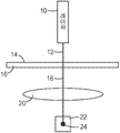
제조된 재료 내의 결함을 측정하기 위해 사용될 수 있는 하나의 방법이 도 1a 및 도 1b에 도시된다. 도 1a를 참조하면, 예를 들어 레이저와 같은 광원(10)이 조사 광 빔(12)을 기준 샘플 재료(16)의 기준 표면(14) 상으로 투사한다. 기준 표면(14)은 실질적으로 평평하고, 왜곡, 밴딩, 기다란 자국 등과 같은 불균일 결함이 없다. 샘플 재료(16)를 통해 투과된 광 빔(18)이 푸리에 변환(Fourier Transform) 렌즈(20)를 통과하고, 센서(22) 상에 이미지화된다. 빔(18)은 광원(10), 렌즈(20) 및 기준 표면(14)의 각도 정렬의 특성인 기준 초점 스폿(24)을 센서(22) 상에 형성한다. 이어서, 예를 들어 X-Y 평면 내에서의 스폿의 위치와 같은 기준 초점 스폿(24)의 선택된 특성이 컴퓨터(도 1a에 도시되지 않음)의 메모리에 저장된다.One method that can be used to measure defects in fabricated materials is shown in Figures 1A and 1B. Referring to FIG. 1A, a
도 1b를 참조하면, 광원(30)이 조사 광 빔(32)을 샘플 재료(36)의 표면(34) 상으로 투사한다. 표면(34)은 예를 들어 왜곡, 밴딩, 기다란 자국 등과 같은 적어도 하나의 불균일 결함을 포함한다. 샘플 재료(36)를 통해 투과된 광 빔(38)이 푸리에 변환 렌즈(40)를 통과하고, 센서(42) 상으로 투사된다. 빔(38)은 샘플 재료(36)의 표면(34)의 특성인 초점 스폿(44)을 센서(42) 상에 형성한다.Referring to FIG. 1B, a
센서(42) 상의 초점 스폿(44)의 선택된 특성이 메모리에 저장된 기준 스폿(24)의 특성과 비교되면, 표면(34) 내의 불균일 결함은 초점 스폿(44)의 측정가능한 변화를 야기할 것이다. 예를 들어, 표면(34) 내의 소정의 불균일 결함은 광 빔(38)의 각도 편차 θ와 초점 스폿(24, 44)의 중심들 사이의 대응하는 선형 편차 x를 야기할 것이다.Uneven defects in the
도 1a 및 도 1b에 도시된 방법과 장치는 샘플 재료의 표면 특성의 일점 측정(one-point measurement)만을 제공한다. 재료의 표면 상의 큰 샘플 영역에 걸쳐 불균일 결함을 측정하기 위해, 레이저 빔이 샘플 영역의 선택된 부분을 가로질러 스캐닝될 수 있으며, 이는 시간 소모적이고, 재료가 제조됨에 따라 샘플 영역의 표면 특성을 실시간으로 신속하게 평가하는 것을 어렵게 할 수 있다.The method and apparatus shown in Figures 1A and 1B provide only one-point measurement of the surface properties of the sample material. The laser beam can be scanned across selected portions of the sample region to measure non-uniform defects over a large sample area on the surface of the material, which is time consuming and requires real time Making it difficult to evaluate quickly.
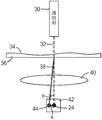
도 2를 참조하면, 표면 불균일도를 측정하기 위한 시스템 및 장치(100)가 조사 광 빔(104)을 방출하는 적어도 하나의 광원(102)을 포함한다. 적합한 광원(102)은 분석될 표면의 유형에 따라 폭넓게 달라질 수 있지만, 레이저와 같은, 명확한 파면을 갖는 광원이 특히 바람직하고, 적합한 레이저는 He-Ne 레이저, 다이오드 레이저 등을 포함한다.Referring to FIG. 2, a system and
조사 광 빔(104)은 빔을 샘플 재료(112)의 표면(110) 상의 선택된 샘플 영역(108) 위에 놓이도록 추가로 확장시키는 광학 렌즈 시스템(106)을 통과한다. 다수의 조사 광 빔(104)이 광원(102)으로서 사용되면, 빔을 샘플 영역(108) 위에 놓이도록 충분히 확장시키는 데 렌즈 시스템(106)이 필요하지 않을 수 있다.The irradiating
예를 들어, 본 명세서에 기술된 분석 방법 및 장치는 샘플 재료(112)의 웨브형 롤의 표면을 검사하기에 특히 적합하지만 이에 제한되지 않는다. 일반적으로, 웨브 롤은 하나의 방향(웨브 폭(cross-web) 방향)으로 고정된 치수를 그리고 직교 방향(웨브 하류(down-web) 방향)으로 미리설정된 또는 부정의 길이를 갖는 임의의 시트형 재료일 수 있는 제조된 웨브 재료를 포함할 수 있다. 시스템(100)을 사용하여 효과적으로 분석될 수 있는 웨브 재료의 예는 표면(110)이 광원(102)에 의해 방출된 광을 고도로 산란시키지 않는 투과성 또는 반사성 샘플 재료(112)를 포함하지만 이에 제한되지 않는다. 예는 금속, 종이, 직물(woven), 부직물(non-woven), 유리, 중합체 필름, 연성 회로 또는 이들의 조합을 포함한다. 금속은 강철 또는 알루미늄과 같은 재료를 포함할 수 있다. 직물 재료는 일반적으로 다양한 천을 포함한다. 부직물은 종이, 필터 매체, 또는 절연 재료와 같은 재료를 포함한다. 필름은 예를 들어 라미네이트 및 코팅된 필름을 비롯한 투명 및 불투명 중합체 필름을 포함한다.For example, the analytical methods and apparatus described herein are particularly suitable for testing the surface of a web-like roll of
표면(110)은 샘플 재료(112)의 넓은 영역에 걸쳐 연장될 수 있는, 예를 들어 반점, 채터, 밴딩, 기다란 자국 및 왜곡(도 2에 도시되지 않음)과 같은 불균일부를 포함한다. 광원(102)과 렌즈 시스템(106)은 특정 표면 분석 응용에 적합하게 크기설정된 샘플 영역(108)을 제공하도록 선택될 수 있다.
2차원 광 빔(114)이 샘플 재료(112)의 표면(110)을 통해 투과되고/되거나 그로부터 반사된 다음에 렌즈들의 어레이(120)에 입사하게 된다. 선형이거나 2차원일 수 있는 렌즈 어레이(120)는 투과된 또는 반사된 광 빔(114)의 적어도 일부분을 캡쳐하기 위해, 본 명세서에서 렌즈릿으로 지칭될 수 있는, 적합한 개수 및 배열의 렌즈 요소들(122)을 포함한다. 렌즈 어레이(120)가 임의의 적합한 크기 및 형상일 수 있지만, 렌즈 어레이(120)의 크기 및 형상은 바람직하게는 렌즈 어레이(120) 내의 모든 렌즈릿(122)이 투과된 광 빔(114)에 의해 채워지도록 선택된다. 다수의 투과된 광 빔(114)이 광원(102)으로서 이용되면, 렌즈 어레이(120) 내의 렌즈릿은 바람직하게는 렌즈 시스템(106)(존재하는 경우)으로부터의 각도 발산과 샘플 재료(112)에 의해 유발되는 각도 편차의 양의 조합이 다수의 투과된 광 빔이 단일 렌즈릿에 입사하게 또는 렌즈릿들 사이의 영역에 입사하게 하지 않도록 배열된다. 다수의 렌즈 어레이(120)는 선택적으로 투과된 광 빔(114)의 크기에 맞도록 서로 인접하게 배치될 수 있다.The two
렌즈릿들(122) 각각은 초점 스폿(150)을 생성하도록 선택되는 만곡된 표면을 포함하고, 렌즈 어레이(120)에 의해 생성되는 초점 스폿의 2차원 어레이(152)는 표면(110)의 샘플 영역(108) 내의 특징부의 특성이다. 도 2에 도시된 실시예에서, 초점 스폿들의 어레이(152)는 이미지화 렌즈 시스템(130)에 의해, 예를 들어 CCD 또는 CMOS 카메라(134)를 포함하는 적합한 센서 시스템(132) 상에 이미지화된다.Each of the
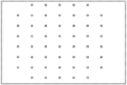
센서 시스템(132)은 카메라(134) 내부에 있거나 그 외부에 있거나 그로부터 원격에 있을 수 있는 프로세서(136)를 포함한다. 프로세서(136)는 메모리에 저장되는 초점 스폿들(154)의 기준 어레이를 포함한다. 초점 스폿들(154)의 기준 어레이는 실질적으로 불균일 결함이 없는 기준 샘플 재료(112)의 장치(100)를 사용한 사전 분석으로부터 형성되거나, 이상적인 샘플 재료의 거동의 이론적인 모델에 기초하여 계산될 수 있다.The
샘플 영역(108)의 임의의 부분 내의 불균일 결함은 샘플 재료(112)의 그 부분을 통해 투과되는 광의 변화를 유발하며, 이는 렌즈릿 어레이(120) 내의 아래에 있는 렌즈릿(122)에 의해 수집된다. 예를 들어, 샘플 영역(108) 내의 불균일 결함은 조사 광 빔의 각도 편향, 각도 발산, 또는 변경된 투과율을 유발할 수 있다. 이들 변경은 초점 스폿들의 기준 어레이에 대해, (1) X-Y 평면 내에서의 초점 스폿들의 위치, (2) 초점 스폿들의 크기, 또는 (3) 초점 스폿들의 세기 중 적어도 하나의 변화를 형성할 수 있다.Uneven defects in any portion of the
도 2에 도시된 실시예에서, 조사 빔(114)의 각도 편향은 샘플 영역(108) 아래에 있는 렌즈릿들(122) 중 적어도 일부에 의해 검출되며, 이는 프로세서(136)의 메모리에 저장된 초점 스폿들(154)의 기준 어레이와 비교할 때, 어레이(152) 내의 초점 스폿들(150) 사이의 X 및 Y 방향들 중 적어도 하나로의 대응하는 변위를 유발한다. 프로세서(136)는 2차원 어레이(152) 내의 각각의 초점 스폿(150)의 X-Y 평면 내에서의 위치를 기준 초점 스폿 어레이 내의 그의 대응하는 기준 초점 스폿(154)의 위치와 비교하기 위해 임의의 적합한 알고리즘을 이용한다. 렌즈 어레이(120) 내의 각각의 렌즈릿(122)에 의해 생성되는 초점 스폿들(150, 154)의 도심(centroid) 영역들 사이의 이러한 선형 변위는 샘플 영역(108)의 대응하는 위에 놓인 영역 내의 불균일 결함의 심각도에 비례한다.2, the angular deflection of the
도 1a 및 도 1b에 도시된 점 측정 장치에 비해, 도 2의 장치는 큰 샘플 영역(108)에 걸쳐 불균일부의 신속한 2차원 맵핑을 가능하게 하기 위해 다수의 점을 동시에 측정한다. 초점 스폿들(150)의 어레이의 2차원 맵은 두 방향(예를 들어, 웨브 재료에서, 웨브 폭 및 웨브 하류 방향)으로의 샘플 균일도의 정확한 표현이다. 또한, 초점 스폿들(154)의 기준 어레이로부터 초점 스폿들(150)의 2차원 어레이의 변위는 프로세서(136) 내의 알고리즘을 사용하여 처리하고 해석하기에 비교적 간단하다.Compared to the point measuring apparatus shown in Figs. 1A and 1B, the apparatus of Fig. 2 simultaneously measures a plurality of points to enable rapid two-dimensional mapping of the non-uniform portion over a
장치(100)의 감도는 주로 2개의 인자: 1) 렌즈 어레이(120) 내의 렌즈릿들(122)의 초점 길이(렌즈릿들(122)의 초점 거리가 길수록, 감도가 높아짐); 및 2) 초점 스폿들(150, 154) 사이의 도심 이동을 추적하기 위해 사용되는 프로세서(136) 내의 이미지화 처리 알고리즘과 센서 시스템(132)의 분해능에 의해 결정된다. 예를 들어, 스폿의 도심이 카메라(134)의 센서 상의 단일 픽셀보다 많은 픽셀과 만나는 경우, 프로세서(136)는 스폿 내에 놓인 픽셀들의 세기들의 도심을 계산한다. 이어서, 어레이 내의 인접한 렌즈릿에 마주하는(subtend) 픽셀들의 영역과 충돌하기 전에 얼마나 많은 픽셀이 남아 있는지에 의해 시스템의 각도 범위가 결정된다.The sensitivity of the
장치(100)에서, 실린더형 렌즈들의 어레이 또는 렌티큘러(lenticular) 렌즈 어레이가 렌즈 어레이를 대체하도록 사용될 수 있고, 라인 스캔 카메라가 CCD 또는 CMOS 카메라를 대체하도록 사용될 수 있다. 그러나, 이러한 대안적인 실시예는 하나의 방향(예를 들어 웨브를 가로지름)으로의 불균일도 측정만을 허용한다.In the
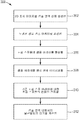
도 3은 재료의 샘플 영역에서 불균일도의 레벨을 결정하기 위해 도 2의 장치를 작동시키는 방법(300)을 예시하는 흐름도이다. 단계(302)에서, 적어도 하나의 광원의 출력 빔이 표면의 선택된 샘플 영역 상에 2차원 조사 빔을 형성한다. 단계(304, 306)에서, 샘플 영역을 통해 투과된 또는 샘플 영역으로부터 반사된 광이 렌즈들의 어레이에 의해 집광되어 대응하는 초점 스폿들의 샘플 어레이를 형성한다. 단계(308)에서, 초점 스폿들의 샘플 어레이가 CCD 카메라와 같은 센서 상에 이미지화된다. 단계(310)에서, 센서 상의 샘플 어레이의 이미지가 기준 초점 스폿 어레이에 대한 선택된 초점 스폿 특성의 선택된 변화를 결정하도록 처리된다. 초점 스폿 특성의 측정가능한 변화의 예는 스폿 위치, 스폿 크기 또는 스폿 세기의 차이를 포함하지만, 이에 제한되지 않는다. 단계(312)에서, 이러한 변화가 샘플 영역의 불균일도를 평가 및/또는 특성화하기 위해 사용된다.FIG. 3 is a flow chart illustrating a
몇몇 실시예에서, 도 2의 장치는 제조 동안 웨브 재료를 검사하기 위해 하나 이상의 검사 시스템에 이용될 수 있다. 제품 내로의 통합을 위해 개별 시트로의 변환 준비가 된 완성된 웨브 롤을 생성하기 위해, 미완성된 웨브 롤이 하나의 웨브 제조 플랜트 내의 또는 다수의 제조 플랜트 내의 다수의 공정 라인 상에서 처리될 수 있다. 각각의 공정에 대해, 웨브가 그로부터 제조 공정으로 공급되는 소스 롤로서 웨브 롤이 사용된다. 각각의 공정 후, 웨브는 전형적으로 다시 웨브 롤로 수집되고, 상이한 제품 라인으로 이동되거나 상이한 제조 플랜트로 운송되며, 거기에서 이는 이어서 풀리고 처리되며 다시 롤로 수집된다. 궁극적으로 완성된 웨브 롤이 생성될 때까지 이러한 공정이 반복된다. 많은 응용에 대해, 웨브 롤들 각각을 위한 웨브 재료는 하나 이상의 웨브 제조 플랜트의 하나 이상의 제조 라인에서 적용되는 다수의 코팅을 구비할 수 있다. 코팅은 일반적으로 제1 제조 공정의 경우에 베이스 웨브 재료의 노출된 표면에 또는 후속 제조 공정의 경우에 이전에 적용된 코팅의 노출된 표면에 적용된다. 코팅의 예는 접착제, 하드코트(hardcoat), 낮은 접착성의 배면 코팅, 금속화된 코팅, 중성 밀도 코팅, 전기 전도성 또는 비전도성 코팅, 또는 이들의 조합을 포함한다.In some embodiments, the apparatus of Figure 2 may be used in one or more inspection systems to inspect web material during fabrication. In order to create a finished web roll ready for conversion into a separate sheet for integration into a product, an unfinished web roll can be processed on multiple process lines in a single web manufacturing plant or in multiple manufacturing plants. For each process, a web roll is used as the source roll, from which the web is fed to the manufacturing process. After each process, the web is typically collected again into a web roll, moved to a different product line, or transported to a different manufacturing plant, where it is then unwound, treated and collected again into a roll. This process is repeated until ultimately a finished web roll is produced. For many applications, the web material for each of the web rolls may comprise a plurality of coatings applied in one or more production lines of one or more web production plants. The coating is generally applied to the exposed surface of the base web material in the case of the first manufacturing process or to the exposed surface of the coating previously applied in the case of a subsequent manufacturing process. Examples of coatings include adhesives, hardcoats, low adhesion back coatings, metallized coatings, neutral density coatings, electrically conductive or nonconductive coatings, or combinations thereof.
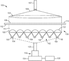
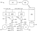
도 4에 도시된 검사 시스템(400)의 예시적인 실시예에서, 웨브(426)의 샘플 영역이 2개의 지지 롤들(423, 425) 사이에 위치된다. 검사 시스템(400)은 샘플 영역(426)으로부터 롤 및 위치 정보를 수집하도록 기준 마크(fiducial mark) 판독기(402)를 제어하는 기준 마크 컨트롤러(401)를 포함한다. 또한, 기준 마크 컨트롤러(401)는 웨브(426)의 선택된 샘플 영역 및/또는 지지 롤러(423, 425)와 연관되는 하나 이상의 고정밀 인코더로부터 위치 신호를 수신할 수 있다. 이러한 위치 신호에 기초하여, 기준 마크 컨트롤러(401)는 각각의 검출된 기준 마크에 대한 위치 정보를 결정한다. 기준 마크 컨트롤러(401)는 롤 및 위치 정보를 웨브(424)의 표면 상의 특징부의 치수에 관한 검출된 데이터와의 관련을 위해 분석 컴퓨터(429)에 전달한다.In the exemplary embodiment of the
시스템(400)은 또한 각각 레이저 광원(450) 및 빔 확장 렌즈 시스템(beam expanding lens system)(452)을 포함하는 하나 이상의 광학 이미지화 시스템(412A 내지 412N)을 포함한다. 광학 시스템(412)은 웨브가 처리됨에 따라 재료의 연속적으로 이동하는 웨브(426)의 표면(424)에 근접하게 위치되고, 디지털 이미지 데이터를 얻기 위해 연속적으로 이동하는 웨브(426)의 순차적인 샘플 영역들을 스캐닝한다.The
광학 시스템(412)은 웨브 표면(424)의 샘플 영역(426) 상에 조사 빔(413)을 생성하기 위해 광 빔을 빔 확장 광학계(452) 내로 투사한다. 웨브(426)의 샘플 영역을 통해 투과된 광(415)은 렌즈 어레이(454)에 의해 집광된다. 렌즈 어레이(454)는 초점 스폿들의 샘플 어레이를 생성하며, 이는 이미지화 렌즈 시스템(456)에 의해 수집되고 센서 시스템(458) 상에 이미지화된다.Optical system 412 projects a light beam into beam expanding optical system 452 to produce an illuminating
이미지 데이터 획득 컴퓨터(427)가 센서 시스템(458)으로부터 이미지 데이터를 수집하고, 이러한 이미지 데이터를 분석 컴퓨터(429)로 전송한다. 분석 컴퓨터(429)는 이미지 획득 컴퓨터(427)로부터의 이미지 데이터의 스트림을 처리하고, 초점 스폿들의 샘플 어레이를 메모리에 저장된 초점 스폿들의 기준 어레이와 비교하기 위해 디지털 이미지를 하나 이상의 알고리즘으로 분석한다. 컴퓨터는 웨브 재료(426)의 샘플 영역에서 불균일도의 레벨을 계산하기 위해 기준 어레이 내의 그의 대응하는 초점 스폿에 대한 샘플 어레이 내의 각각의 초점 스폿의 변화를 평가한다. 분석 컴퓨터(429)는 그 결과를 적절한 사용자 인터페이스 상에 표시할 수 있고/있거나 그 결과를 데이터베이스(431)에 저장할 수 있다.The image data acquisition computer 427 collects image data from the sensor system 458 and transmits the image data to the
도 4에 도시된 검사 시스템(400)은 웨브 표면(424) 내에서의 불균일 결함의 존재를 검출하기 위한 알고리즘을 적용하기 위해 웨브 제조 플랜트 내에 사용될 수 있다. 검사 시스템(400)은 또한 웨브가 제조됨에 따라 각각의 결함의 심각도를 실시간으로 지시하는 출력 데이터를 제공할 수 있다. 예를 들어, 컴퓨터 검사 시스템은 불균일부의 존재와 그 심각도에 관해 웨브 제조 플랜트 내의, 공정 엔지니어와 같은 사용자에게 실시간 피드백을 제공하여, 사용자가 제조를 상당히 지연시키거나 대량의 사용불가 재료를 생성함이 없이 문제를 해결하기 위해 공정 조건을 조절함으로써 재료의 특정 배치(batch) 또는 일련의 배치 내의 발생하는 불균일부에 신속히 대응하게 할 수 있다. 컴퓨터 검사 시스템(400)은 궁극적으로 불균일부에 대한 등급 라벨을 할당함으로써(예컨대, "양호" 또는 "불량") 또는 주어진 샘플의 불균일 심각도의 측정치를 연속 스케일 또는 더욱 정확하게는 샘플링된 스케일로 생성함으로써 심각도 레벨을 계산하기 위한 알고리즘을 적용할 수 있다.The
분석 컴퓨터(429)는 웨브(426)의 샘플 영역에 대한 불균일도 등급 또는 웨브(426)에 대한 롤 식별 정보 및 가능하게는 각각의 측정된 특징부에 대한 위치 정보를 비롯한 다른 정보를 데이터베이스(431) 내에 저장할 수 있다. 예를 들어, 분석 컴퓨터(429)는 공정 라인의 좌표계 내에서 불균일부의 각각의 측정된 영역의 이미지 영역 또는 공간 위치를 결정하기 위해 기준 마크 컨트롤러(401)에 의해 생성된 위치 데이터를 이용할 수 있다. 즉, 기준 마크 컨트롤러(401)로부터의 위치 데이터에 기초하여, 분석 컴퓨터(429)는 현재 공정 라인에 의해 사용되는 좌표계 내에서 불균일부의 각각의 영역에 대한 x, y 및 가능하게는 z 위치 또는 범위를 결정한다. 예를 들어, 좌표계는 x 치수가 웨브(426)를 가로지른 거리를 나타내고, y 치수가 웨브의 길이를 따른 거리를 나타내며, z 치수가 웨브에 이전에 적용된 코팅, 재료 또는 다른 층의 개수에 기초할 수 있는 웨브의 높이를 나타내도록 정의될 수 있다. 게다가, x, y, z 좌표계에 대한 원점은 공정 라인 내의 물리적 위치에 정의될 수 있고, 전형적으로 웨브(426)의 초기 공급 배치와 관련된다.The
데이터베이스(431)는 데이터 저장 파일 또는 하나 이상의 데이터베이스 서버 상에서 실행되는 하나 이상의 데이터베이스 관리 시스템(DBMS)을 비롯한 다수의 상이한 형태 중 임의의 형태로 구현될 수 있다. 데이터베이스 관리 시스템은 예를 들어 관계형(RDBMS), 계층형(HDBMS), 다차원형(MDBMS), 객체 지향형(ODBMS 또는 OODBMS) 또는 객체 관계형(ORDBMS) 데이터베이스 관리 시스템일 수 있다. 일례로서, 데이터베이스(431)는 미국 워싱턴주 레드몬드 소재의 마이크로소프트 코포레이션(Microsoft Corporation)으로부터 상표명 SQL 서버(Server)로 입수가능한 관계형 데이터베이스로서 구현된다.The
일단 공정이 종료되었으면, 분석 컴퓨터(429)는 데이터베이스(431)에 수집된 데이터를 네트워크(439)를 통해 변환 제어 시스템(440)으로 전송할 수 있다. 예를 들어, 분석 컴퓨터(429)는 롤 정보뿐만 아니라, 특징부 치수 및/또는 이상(anomaly) 정보 및 각각의 특징부에 대한 각각의 서브-이미지를 후속 오프라인 상세 분석을 위해 변환 제어 시스템(440)에 전달할 수 있다. 예를 들어, 특징부 치수 정보가 데이터베이스(431)와 변환 제어 시스템(440) 사이의 데이터베이스 동기화에 의해 전달될 수 있다.Once the process is complete, the
몇몇 실시예에서, 분석 컴퓨터(429)보다는 변환 제어 시스템(440)이 제품들 중, 각각의 이상이 결함을 야기할 수 있는 제품들을 결정할 수 있다. 일단 완성된 웨브 롤에 대한 데이터가 데이터베이스(431)에 수집되었으면, 데이터는 변환 사이트에 전달될 수 있고/있거나 이상을 웨브 롤 상에 마킹하되, 웨브의 표면 상에 제거가능한 또는 세척가능한 마크로 직접, 또는 웨브 상에 이상을 마킹하기 전에 또는 그 동안에 웨브에 적용될 수 있는 커버 시트 상에 마킹하기 위해 사용될 수 있다.In some embodiments, rather than the
분석 컴퓨터(429)의 구성요소는 적어도 부분적으로 하나 이상의 하드웨어 마이크로프로세서, 디지털 신호 프로세서(DSP), 응용 특정 집적 회로(ASIC), 현장 프로그램가능 게이트 어레이(FPGA), 또는 임의의 다른 등가 집적 회로 또는 개별 논리 회로뿐만 아니라 그러한 구성요소들의 임의의 조합을 비롯한, 분석 컴퓨터(429)의 하나 이상의 프로세서에 의해 실행되는 소프트웨어 명령어로서 구현될 수 있다. 소프트웨어 명령어는 랜덤 액세스 메모리(RAM), 판독 전용 메모리(ROM), 프로그램가능 판독 전용 메모리(PROM), 소거가능 및 프로그램가능 판독 전용 메모리(EPROM), 전자적 소거가능 및 프로그램가능 판독 전용 메모리(EEPROM), 플래시 메모리, 하드 디스크, CD-ROM, 플로피 디스크, 카세트, 자기 매체, 광학 매체, 또는 다른 컴퓨터-판독가능 저장 매체와 같은 비-일시적 컴퓨터 판독가능 매체 내에 저장될 수 있다.The components of
예의 목적을 위해 제조 플랜트 내에 위치되는 것으로 도시되지만, 분석 컴퓨터(429)는 제조 플랜트 외부에, 예컨대 중앙 위치에 또는 변환 사이트에 위치될 수 있다. 예를 들어, 분석 컴퓨터(429)는 변환 제어 시스템(440) 내에서 작동할 수 있다. 다른 예에서, 기술된 구성요소는 단일 컴퓨팅 플랫폼 상에서 실행되며, 동일한 소프트웨어 시스템 내에 집적될 수 있다.Although shown as being located within the manufacturing plant for purposes of example, the
이제 본 개시 내용의 청구 요지가 하기의 비제한적인 예를 참조하여 기술될 것이다.The subject matter of the present disclosure will now be described with reference to the following non-limiting examples.
예Yes
도 2의 장치를 준비하였고, 레이저(102)에 의해 방출된 빔(104)을 약 14.5 ㎠(2.25 제곱 인치)의 면적을 커버하도록 렌즈 시스템(106)에 의해 확장시켰다. 약 25.8 ㎠(4 제곱 인치)의 면적을 갖는 렌즈릿 어레이(120)가 샘플 재료(112)의 샘플 영역(108)을 통해 투과된 광을 캡쳐함에 따라, 초점 스폿들의 샘플 어레이(152)가 이미지화 렌즈 시스템(130)을 통해 CCD 카메라(134)에 이미지화되었다.The apparatus of FIG. 2 was prepared and the
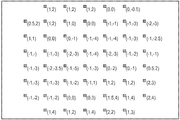
도 5는 초점 스폿들(154)의 기준 어레이의 이미지를 도시하고, 도 6은 확장된 레이저 빔과 렌즈릿 어레이(120) 사이에 재료의 불균일 샘플이 배치된 때 생성된 초점 스폿들(150)의 이동된 샘플 어레이를 도시한다. 도 6에 열거된 수치 값은 초점 스폿들(154)의 기준 어레이의 이미지에 대한 초점 스폿들(150)의 샘플 어레이의 이미지의 X 및 Y 변위이다.Figure 5 shows an image of the reference array of
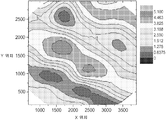
도 7은 도 6에 도시된 데이터로부터 계산된 웨브 왜곡 진폭의 표면 등고선 지도이다. 웨브 경사 방향과 같은 다른 정보가 또한 얻어질 수 있다.7 is a surface contour map of the web distortion amplitude calculated from the data shown in Fig. Other information such as web warp direction can also be obtained.
본 발명의 다양한 실시예가 설명되었다. 이들 및 다른 실시예가 하기 특허청구범위의 범주 내에 속한다.Various embodiments of the present invention have been described. These and other embodiments fall within the scope of the following claims.
Claims (42)
상기 샘플 영역을 통해 투과된 또는 상기 샘플 영역으로부터 반사된 광을 렌즈들의 어레이로 집광하여 초점 스폿(focus spot)들의 샘플 어레이(sample array)를 형성하는 단계와,
상기 초점 스폿들의 샘플 어레이를 이미지화 렌즈를 통해 센서 상에 이미지화하는 단계와,
상기 샘플 영역 내에서의 불균일도의 레벨을 결정하기 위해 상기 초점 스폿들의 샘플 어레이의 이미지를 초점 스폿들의 기준 어레이(reference array)와 비교하는 단계를 포함하는
방법.
Forming a two-dimensional interrogating beam on a selected sample area of the surface;
Focusing the light transmitted through the sample region or reflected from the sample region into an array of lenses to form a sample array of focus spots,
Imaging the sample array of focal spots onto a sensor via an imaging lens;
Comparing the image of the sample array of focal spots with a reference array of focal spots to determine a level of non-uniformity within the sample area
Way.
광원은 레이저를 포함하는
방법.
The method according to claim 1,
The light source includes a laser
Way.
상기 2차원 조사 빔을 형성하기 위해 단일 광원의 출력 빔이 적어도 하나의 빔 확장 렌즈(beam expanding lens)에 의해 확장되는
방법.
The method according to claim 1,
Wherein the output beam of a single light source is expanded by at least one beam expanding lens to form the two-dimensional illumination beam
Way.
상기 2차원 조사 빔은 다수의 광원에 의해 형성되는
방법.
The method according to claim 1,
The two-dimensional irradiation beam is formed by a plurality of light sources
Way.
상기 센서는 CCD 또는 CMOS 카메라를 포함하는
방법.
The method according to claim 1,
The sensor may comprise a CCD or CMOS camera
Way.
상기 이미지화 렌즈는 (1) 단일 요소 렌즈, 또는 (2) 다중 요소 렌즈 조합을 포함하는
방법.
6. The method of claim 5,
The imaging lens comprises (1) a single element lens, or (2) a combination of multiple element lenses
Way.
상기 비교하는 단계는 상기 센서 내부에 있는 프로세서(processor)에 의해 수행되는
방법.
6. The method of claim 5,
Wherein the comparing is performed by a processor within the sensor
Way.
상기 비교하는 단계는 상기 센서로부터 원격에 있는 프로세서에 의해 수행되는
방법.
6. The method of claim 5,
Wherein the comparing is performed by a processor remote from the sensor
Way.
상기 샘플은 재료의 이동 웨브(web)인
방법.
The method according to claim 1,
The sample is a moving web of material
Way.
상기 비교하는 단계는 상기 샘플 어레이 내의 상기 초점 스폿들의 하기 특성들: X-Y 평면 내에서의 변위, 크기 및 세기 중 적어도 하나를 상기 기준 어레이 내의 상기 초점 스폿들의 특성들과 비교하는
방법.
The method according to claim 1,
Wherein the comparing comprises comparing at least one of the following properties of the focal spots in the sample array: displacement, magnitude and intensity within the XY plane with the characteristics of the focal spots in the reference array
Way.
상기 비교하는 단계는 상기 기준 어레이 내의 상기 초점 스폿들의 위치에 대한 상기 샘플 어레이 내의 상기 초점 스폿들의 X-Y 평면 내에서의 변위를 비교하는
방법.
The method according to claim 1,
Wherein the comparing comprises comparing displacements in the XY plane of the focus spots in the sample array relative to positions of the focus spots in the reference array
Way.
상기 집광된 광은 상기 샘플 영역을 통해 투과되는
방법.
The method according to claim 1,
The condensed light is transmitted through the sample region
Way.
상기 표면의 상기 샘플 영역을 통해 투과된 또는 상기 샘플 영역으로부터 반사된 광을 캡쳐하여 초점 스폿들의 샘플 어레이를 형성하는 렌즈릿 어레이(lenslet array)와,
상기 렌즈릿 어레이에 의해 생성된 상기 초점 스폿들의 샘플 어레이를 센서 상에 이미지화하는 이미지화 렌즈와,
초점 스폿들의 기준 어레이에 대해, 상기 초점 스폿들의 샘플 어레이의 특성의 하기 변화들: (1) 상기 샘플 어레이 내의 초점 스폿의 X-Y 평면 내에서의 변위, (2) 상기 샘플 어레이 내의 초점 스폿의 크기, 및 (3) 상기 샘플 어레이 내의 초점 스폿의 세기 중 적어도 하나를 결정하는 프로세서 - 상기 변화들은 상기 샘플 영역 내에서의 불균일도의 레벨을 나타냄 - 를 포함하는
장치.
At least one light source for forming a two-dimensional illumination beam on a selected sample area of a surface,
A lenslet array that captures light transmitted through the sample region of the surface or reflected from the sample region to form a sample array of focal spots,
An imaging lens for imaging the sample array of focus spots produced by the lenslet array onto a sensor,
For a reference array of focal spots, the following changes in the characteristics of the sample array of focal spots are: (1) displacement in the XY plane of the focal spot in the sample array, (2) magnitude of the focal spot in the sample array, And (3) a processor for determining at least one of the focal spot intensities in the sample array, wherein the variations represent a level of non-uniformity within the sample region
Device.
상기 프로세서는 상기 초점 스폿들의 기준 어레이에 대한 상기 샘플 어레이 내의 초점 스폿의 상기 변위를 결정하는
장치.
14. The method of claim 13,
Wherein the processor determines the displacement of the focus spot in the sample array relative to the reference array of focus spots
Device.
상기 광원과 상기 표면 사이에 빔 확장 렌즈를 더 포함하는
장치.
14. The method of claim 13,
Further comprising a beam expanding lens between the light source and the surface
Device.
다수의 광원이 상기 조사 빔을 형성하는
장치.
14. The method of claim 13,
A plurality of light sources form the irradiation beam
Device.
상기 광원은 레이저인
장치.
14. The method of claim 13,
The light source is a laser
Device.
상기 이미지화 렌즈는 (1) 단일 요소 렌즈, 또는 (2) 다중 요소 렌즈 조합을 포함하는
장치.
14. The method of claim 13,
The imaging lens comprises (1) a single element lens, or (2) a combination of multiple element lenses
Device.
상기 센서는 CCD 또는 CMOS 카메라를 포함하는
장치.
14. The method of claim 13,
The sensor may comprise a CCD or CMOS camera
Device.
상기 프로세서는 상기 센서 내부에 있는
장치.
14. The method of claim 13,
Wherein the processor
Device.
상기 프로세서는 상기 센서로부터 원격에 있는
장치.
14. The method of claim 13,
Wherein the processor is further configured to:
Device.
상기 렌즈릿 어레이는 상기 샘플 영역을 통해 투과된 광을 캡쳐하는
장치.
14. The method of claim 13,
The lenslet array captures light transmitted through the sample region
Device.
상기 표면의 상기 선택된 샘플 영역 상에 2차원 조사 빔을 형성하는 광원과,
상기 표면의 상기 샘플 영역을 통해 투과된 또는 상기 샘플 영역으로부터 반사된 광을 캡쳐하여 초점 스폿들의 샘플 어레이를 형성하는 렌즈릿 어레이와,
상기 초점 스폿들의 샘플 어레이를 센서 상에 이미지화하기 위한 이미지화 렌즈와,
상기 샘플 영역 내에서의 불균일도의 레벨을 결정하기 위해, 초점 스폿들의 기준 어레이에 대해, 상기 샘플 어레이 내의 상기 초점 스폿들의 X-Y 평면 내에서의 변위, 크기 및 세기 중 적어도 하나를 측정하는 프로세서를 포함하는
시스템.
A system for monitoring distortion in selected sample areas on a surface of a material,
A light source for forming a two-dimensional irradiation beam on the selected sample region of the surface,
A lenslet array for capturing light transmitted through the sample region of the surface or reflected from the sample region to form a sample array of focal spots,
An imaging lens for imaging the sample array of focus spots onto a sensor,
Magnitude and intensity within the XY plane of the focal spots in the sample array for a reference array of focal spots to determine the level of non-uniformity within the sample area doing
system.
상기 프로세서는 상기 기준 어레이에 대해, 상기 샘플 어레이 내의 각각의 초점 스폿의 X-Y 방향으로의 상기 변위를 측정하는
시스템.
24. The method of claim 23,
The processor is configured to determine, for the reference array, the displacement in XY directions of each focus spot in the sample array
system.
상기 렌즈릿 어레이는 상기 샘플 영역의 상기 표면을 통해 투과된 광을 캡쳐하는
시스템.
24. The method of claim 23,
Wherein the lenslet array captures light transmitted through the surface of the sample region
system.
상기 재료의 상기 표면은 고정되지 않은
시스템.
24. The method of claim 23,
The surface of the material is not fixed
system.
상기 광원은 레이저이고, 상기 시스템은 상기 레이저와 상기 표면 사이에 빔 확장 렌즈를 더 포함하는
시스템.
24. The method of claim 23,
Wherein the light source is a laser and the system further comprises a beam expanding lens between the laser and the surface
system.
상기 이미지화 렌즈는 (1) 단일 요소 렌즈, 또는 (2) 다중 요소 렌즈 조합을 포함하는
시스템.
24. The method of claim 23,
The imaging lens comprises (1) a single element lens, or (2) a combination of multiple element lenses
system.
상기 프로세서는 상기 센서로부터 원격에 있는
시스템.
24. The method of claim 23,
Wherein the processor is further configured to:
system.
상기 샘플 영역을 통해 투과된 광을 렌즈릿 어레이 상에 집광시키는 단계 - 상기 렌즈릿 어레이는 대응하는 초점 스폿들의 샘플 어레이를 형성함 - 와,
상기 초점 스폿들의 샘플 어레이를 이미지화 렌즈를 통해 카메라의 센서 상에 이미지화하는 단계와,
초점 스폿들의 기준 어레이에 대해, 상기 샘플 어레이 내의 각각의 초점 스폿의 X-Y 방향으로의 변위를 측정하도록 상기 센서 상의 상기 이미지를 처리하고, 상기 초점 스폿들의 상기 측정된 변위들에 기초하여 상기 샘플 영역 내에서의 불균일도를 계산하는 단계를 포함하는
방법.
Positioning a light source proximate a surface of an unfixed web of flexible material, the light source forming a two-dimensional illumination beam on a selected sample area of the surface;
Collecting light transmitted through the sample region onto a lenslet array, the lenslet array forming a sample array of corresponding focal spots,
Imaging the sample array of focal spots onto a sensor of the camera via an imaging lens;
Processing the image on the sensor to measure displacements in the X and Y directions of respective focus spots in the sample array for a reference array of focal spots and processing the image on the sensor in the sample area based on the measured displacements of the focus spots And calculating a non-uniformity in
Way.
상기 이미지화 렌즈는 (1) 단일 요소 렌즈, 또는 (2) 다중 요소 렌즈 조합을 포함하는
방법.
31. The method of claim 30,
The imaging lens comprises (1) a single element lens, or (2) a combination of multiple element lenses
Way.
상기 초점 스폿들의 샘플 어레이의 상기 이미지는 상기 카메라 내부에 있는 프로세서에 의해 처리되는
방법.
31. The method of claim 30,
Wherein the image of the sample array of focus spots is processed by a processor within the camera
Way.
상기 초점 스폿들의 샘플 어레이의 상기 이미지는 상기 카메라로부터 원격에 있는 프로세서에 의해 처리되는
방법.
31. The method of claim 30,
Wherein the image of the sample array of focus spots is processed by a processor remote from the camera
Way.
광원을 가요성 재료의 고정되지 않은 웨브의 표면에 근접하게 위치시키는 단계 - 상기 광원은 적어도 하나의 레이저 및 빔 확장 렌즈를 포함하고, 상기 광원은 상기 표면의 선택된 샘플 영역 상에 2차원 조사 빔을 형성함 - 와,
상기 샘플 영역을 통해 투과된 또는 상기 샘플 영역으로부터 반사된 광을 렌즈릿 어레이 상에 집광시키는 단계 - 상기 렌즈릿 어레이는 대응하는 초점 스폿들의 샘플 어레이를 형성함 - 와,
상기 초점 스폿들의 샘플 어레이를 이미지화 렌즈를 통해 카메라의 센서 상에 이미지화하는 단계와,
초점 스폿들의 기준 어레이에 대해, 상기 샘플 어레이 내의 각각의 초점 스폿의 X-Y 방향으로의 변위를 측정하도록 상기 센서 상의 상기 이미지를 처리하고, 상기 측정된 변위들에 기초하여 상기 샘플 영역 내에서의 불균일도의 레벨을 계산하는 단계를 포함하는
방법.
CLAIMS What is claimed is: 1. A method for inspecting a web material in real time as it is manufactured and calculating a distortion level of a selected sample area in a surface of the web material,
Positioning a light source proximate a surface of an unfixed web of flexible material, the light source comprising at least one laser and a beam expanding lens, the light source having a two-dimensional illumination beam on a selected sample area of the surface Forming,
Focusing the light transmitted through the sample region or reflected from the sample region onto a lenslet array, the lenslet array forming a sample array of corresponding focal spots,
Imaging the sample array of focal spots onto a sensor of the camera via an imaging lens;
Processing the image on the sensor to measure displacements in the X and Y directions of respective focus spots in the sample array for a reference array of focal spots and calculating a non-uniformity in the sample area based on the measured displacements ≪ / RTI >
Way.
상기 이미지화 렌즈는 (1) 단일 요소 렌즈, 또는 (2) 다중 요소 렌즈 조합을 포함하는
방법.
35. The method of claim 34,
The imaging lens comprises (1) a single element lens, or (2) a combination of multiple element lenses
Way.
상기 이미지는 CCD 카메라로부터 원격에 있는 프로세서에 의해 처리되는
방법.
35. The method of claim 34,
The image is processed by a processor remote from the CCD camera
Way.
상기 계산된 불균일도의 레벨을 사용자에게 출력하기 위한 사용자 인터페이스를 제공하는 단계를 더 포함하는
방법.
35. The method of claim 34,
And providing a user interface for outputting the level of the calculated non-uniformity to a user
Way.
상기 출력에 응답하여 상기 제조된 웨브 재료에 대한 공정 제어 파라미터를 업데이트하는 단계를 더 포함하는
방법.
39. The method of claim 37,
And updating the process control parameters for the fabricated web material in response to the output
Way.
표면의 선택된 샘플 영역 상에 2차원 조사 빔을 형성하는 광원과,
상기 표면의 상기 샘플 영역을 통해 투과된 광을 캡쳐하여 초점 스폿들의 샘플 어레이를 형성하는 렌즈릿 어레이와,
상기 초점 스폿들의 샘플 어레이를 센서 상에 이미지화하기 위한 이미지화 렌즈와,
초점 스폿들의 기준 어레이에 대한 상기 초점 스폿들의 샘플 어레이의 특성의 측정된 변화에 기초하여 상기 샘플 영역 내에서의 불균일도의 레벨을 결정하기 위한 컴퓨터 실행 소프트웨어를 포함하는
온라인 컴퓨터 검사 시스템.
An on-line computer inspection system for inspecting a web material in real time,
A light source for forming a two-dimensional irradiation beam on a selected sample area of the surface,
A lenslet array for capturing light transmitted through the sample region of the surface to form a sample array of focal spots,
An imaging lens for imaging the sample array of focus spots onto a sensor,
And computer executable software for determining a level of non-uniformity within the sample region based on a measured change in a characteristic of the sample array of focus spots with respect to a reference array of focus spots
Online computer inspection system.
웨브 검사 모델을 저장하기 위한 메모리를 더 포함하고, 상기 컴퓨터는 상기 샘플 영역 내의 상기 불균일도를 상기 모델과 비교하고 상기 웨브 재료 내의 불균일 결함의 심각도를 계산하기 위한 소프트웨어를 실행하는
온라인 컴퓨터 검사 시스템.
40. The method of claim 39,
Further comprising a memory for storing a web inspection model, the computer executing software for comparing the non-uniformity in the sample region with the model and calculating the severity of non-uniform defects in the web material
Online computer inspection system.
결함의 심각도를 사용자에게 출력하기 위한 사용자 인터페이스를 더 포함하는
온라인 컴퓨터 검사 시스템.
40. The method of claim 39,
Further comprising a user interface for outputting the severity of the defect to the user
Online computer inspection system.
상기 소프트웨어 명령어들은 컴퓨터 프로세서로 하여금,
웨브 재료의 제조 동안 상기 웨브 재료의 표면 상의 하나 이상의 샘플 영역의 측정된 초점 스폿들의 샘플 어레이의 이미지를 온라인 컴퓨터 검사 시스템으로 수신하게 하고,
상기 초점 스폿들의 샘플 어레이의 상기 이미지를 초점 스폿들의 기준 어레이와 비교하게 하고,
상기 샘플 어레이 내의 상기 초점 스폿들과 상기 기준 어레이 내의 상기 초점 스폿들 사이의 선택된 특성의 변화에 기초하여 상기 웨브 재료 내의 불균일 결함의 심각도를 계산하게 하는
비-일시적 컴퓨터 판독가능 매체.17. A non-transitory computer readable medium comprising software instructions,
The software instructions cause a computer processor to:
Cause the on-line computer inspection system to receive an image of a sample array of measured focus spots of one or more sample areas on a surface of the web material during fabrication of the web material,
To compare the image of the sample array of focal spots with a reference array of focal spots,
To calculate the severity of nonuniformity defects in the web material based on changes in selected characteristics between the focal spots in the sample array and the focal spots in the reference array
Non-transient computer readable medium.
Applications Claiming Priority (3)
| Application Number | Priority Date | Filing Date | Title |
|---|---|---|---|
| US201161578174P | 2011-12-20 | 2011-12-20 | |
| US61/578,174 | 2011-12-20 | ||
| PCT/US2012/068935 WO2013096003A1 (en) | 2011-12-20 | 2012-12-11 | Sensor for measuring surface non-uniformity |
Publications (1)
| Publication Number | Publication Date |
|---|---|
| KR20140105593A true KR20140105593A (en) | 2014-09-01 |
Family
ID=48669363
Family Applications (1)
| Application Number | Title | Priority Date | Filing Date |
|---|---|---|---|
| KR1020147020263A KR20140105593A (en) | 2011-12-20 | 2012-12-11 | Sensor for measuring surface non-uniformity |
Country Status (8)
| Country | Link |
|---|---|
| US (1) | US20140362371A1 (en) |
| EP (1) | EP2795250A4 (en) |
| JP (1) | JP2015503110A (en) |
| KR (1) | KR20140105593A (en) |
| CN (1) | CN104797906A (en) |
| BR (1) | BR112014014823A2 (en) |
| SG (1) | SG11201403446XA (en) |
| WO (1) | WO2013096003A1 (en) |
Families Citing this family (3)
| Publication number | Priority date | Publication date | Assignee | Title |
|---|---|---|---|---|
| CN106970049B (en) * | 2017-05-15 | 2024-01-02 | 中国工程物理研究院激光聚变研究中心 | Transmission distribution measuring system and method |
| CN108007397A (en) * | 2018-01-09 | 2018-05-08 | 常州华达科捷光电仪器有限公司 | A kind of Laser Measuring Barebone |
| CN109870128B (en) * | 2019-03-19 | 2022-06-28 | 青岛科技大学 | Micro-nano structure morphology real-time monitoring optical path system in ink-jet printing |
Family Cites Families (17)
| Publication number | Priority date | Publication date | Assignee | Title |
|---|---|---|---|---|
| DE2808359C3 (en) * | 1978-02-27 | 1980-09-04 | Erwin Sick Gmbh Optik-Elektronik, 7808 Waldkirch | Finding device for holes in lanes |
| DE3334357C2 (en) * | 1983-09-22 | 1986-04-10 | Erwin Sick Gmbh Optik-Elektronik, 7808 Waldkirch | Optical fault locator for railways |
| JPH0641923B2 (en) * | 1988-09-20 | 1994-06-01 | 株式会社東芝 | Surface inspection device |
| US5966212A (en) * | 1996-07-18 | 1999-10-12 | Pixel Systems, Inc. | High-speed, high-resolution, large area inspection using multiple optical fourier transform cells |
| JP2000180373A (en) * | 1998-12-15 | 2000-06-30 | Hoya Corp | Method and apparatus for inspection of defect |
| US7830522B2 (en) * | 2002-09-25 | 2010-11-09 | New York University | Method and apparatus for determining reflectance data of a subject |
| CN1247956C (en) * | 2002-12-25 | 2006-03-29 | 合肥工业大学 | Parallel astigmatic three-dimensional focusing detecting method and apparatus thereof |
| US7292333B2 (en) * | 2003-06-24 | 2007-11-06 | Corning Incorporated | Optical interrogation system and method for 2-D sensor arrays |
| KR100662904B1 (en) * | 2004-03-09 | 2007-01-02 | 삼성전자주식회사 | The method and device for discriminating the deflecting disc |
| EP1863594B1 (en) * | 2005-03-09 | 2011-01-26 | 3M Innovative Properties Company | Apparatus and method for making microreplicated article |
| CA2648305C (en) * | 2006-04-07 | 2012-10-16 | Amo Wavefront Sciences, Llc | Geometric measurement system and method of measuring a geometric characteristic of an object |
| CN1971232B (en) * | 2006-12-13 | 2010-06-16 | 中国科学院光电技术研究所 | Hartmann wavefront sensor with active alignment function and detection method therefor |
| BRPI0811658A2 (en) * | 2007-06-19 | 2015-02-10 | 3M Innovative Properties Co | "SYSTEMS AND METHODS FOR IDENTIFYING A BLANK POSITION" |
| US7777872B2 (en) * | 2007-07-31 | 2010-08-17 | Alcon Research, Ltd. | Method of measuring diffractive lenses |
| US8755101B2 (en) * | 2007-12-28 | 2014-06-17 | Rolling Optics Ab | Method of producing a microstructured product |
| KR20130024900A (en) * | 2010-04-01 | 2013-03-08 | 쓰리엠 이노베이티브 프로퍼티즈 컴파니 | Precision control of web material having micro-replicated lens array |
| CN102226738B (en) * | 2011-03-25 | 2013-03-13 | 宁波大学 | Infrared glass non-uniformity detection method |
-
2012
- 2012-12-11 EP EP12860619.1A patent/EP2795250A4/en not_active Withdrawn
- 2012-12-11 SG SG11201403446XA patent/SG11201403446XA/en unknown
- 2012-12-11 BR BR112014014823A patent/BR112014014823A2/en not_active IP Right Cessation
- 2012-12-11 WO PCT/US2012/068935 patent/WO2013096003A1/en active Application Filing
- 2012-12-11 KR KR1020147020263A patent/KR20140105593A/en not_active Application Discontinuation
- 2012-12-11 JP JP2014549117A patent/JP2015503110A/en not_active Withdrawn
- 2012-12-11 US US14/366,399 patent/US20140362371A1/en not_active Abandoned
- 2012-12-11 CN CN201280063616.2A patent/CN104797906A/en active Pending
Also Published As
| Publication number | Publication date |
|---|---|
| US20140362371A1 (en) | 2014-12-11 |
| EP2795250A4 (en) | 2015-09-16 |
| WO2013096003A1 (en) | 2013-06-27 |
| BR112014014823A2 (en) | 2017-06-13 |
| CN104797906A (en) | 2015-07-22 |
| EP2795250A1 (en) | 2014-10-29 |
| JP2015503110A (en) | 2015-01-29 |
| SG11201403446XA (en) | 2014-10-30 |
Similar Documents
| Publication | Publication Date | Title |
|---|---|---|
| JP6506274B2 (en) | Multi-scale uniformity analysis of materials | |
| US20150009301A1 (en) | Method and apparatus for measuring the three dimensional structure of a surface | |
| WO2016070155A1 (en) | Measurement systems having linked field and pupil signal detection | |
| Ding et al. | A laser-based machine vision measurement system for laser forming | |
| TWI794400B (en) | Infrared light transmission inspection for continuous moving web | |
| KR20140105593A (en) | Sensor for measuring surface non-uniformity | |
| KR20190128151A (en) | Cylindrical Surface Inspection Apparatus and Cylindrical Surface Inspection Method | |
| Rico et al. | Adjustment recommendations of a conoscopic holography sensor for a reliable scanning of surfaces with roughness grades obtained by different processes | |
| US20140240720A1 (en) | Linewidth measurement system | |
| Mendes et al. | Dual-scanning system for optical estimation of pilling formation | |
| Mizutani et al. | Structure estimation of deep neural network for triangulation displacement sensors | |
| JP7207386B2 (en) | Surface defect inspection method, surface defect inspection device, steel sheet manufacturing method, steel sheet quality control method, and steel sheet manufacturing equipment | |
| US20220011238A1 (en) | Method and system for characterizing surface uniformity | |
| JP2022166688A5 (en) | ||
| JP2001349714A (en) | Uniformity evaluation method of mesh-shaped pattern | |
| JP2014529086A5 (en) | ||
| US11867630B1 (en) | Fixture and method for optical alignment in a system for measuring a surface in contoured glass sheets | |
| Tao et al. | Calibration and image enhancement algorithm of portable structured light 3D gauge system for improving accuracy | |
| Feng et al. | Optical difference engine for defect inspection in highly-parallel manufacturing processes | |
| Bringier et al. | High-speed optical 3D measurement device for quality control of aircraft rivet | |
| Sieczka | Feasibility of moiré contouring for flatness checking of steel plates | |
| US9658169B2 (en) | System and method of characterizing micro-fabrication processes | |
| Xu et al. | Using variable homography to measure emergent fibers on textile fabrics | |
| JP2009133729A (en) | Method and device for inspecting irregularity of periodic pattern | |
| Meguellati et al. | Optical device for precision Moiré topography of micro surfaces |
Legal Events
| Date | Code | Title | Description |
|---|---|---|---|
| WITN | Application deemed withdrawn, e.g. because no request for examination was filed or no examination fee was paid |