JP6506274B2 - Multi-scale uniformity analysis of materials - Google Patents
Multi-scale uniformity analysis of materials Download PDFInfo
- Publication number
- JP6506274B2 JP6506274B2 JP2016525899A JP2016525899A JP6506274B2 JP 6506274 B2 JP6506274 B2 JP 6506274B2 JP 2016525899 A JP2016525899 A JP 2016525899A JP 2016525899 A JP2016525899 A JP 2016525899A JP 6506274 B2 JP6506274 B2 JP 6506274B2
- Authority
- JP
- Japan
- Prior art keywords
- uniformity
- image
- interest
- patch
- region
- Prior art date
- Legal status (The legal status is an assumption and is not a legal conclusion. Google has not performed a legal analysis and makes no representation as to the accuracy of the status listed.)
- Active
Links
- 239000000463 material Substances 0.000 title claims description 123
- 238000004458 analytical method Methods 0.000 title description 18
- 238000000034 method Methods 0.000 claims description 97
- 238000007689 inspection Methods 0.000 claims description 19
- 238000012545 processing Methods 0.000 claims description 18
- 230000000694 effects Effects 0.000 claims description 9
- 239000004745 nonwoven fabric Substances 0.000 claims description 9
- 229920006254 polymer film Polymers 0.000 claims description 9
- 238000000576 coating method Methods 0.000 claims description 7
- 239000000123 paper Substances 0.000 claims description 6
- 239000002759 woven fabric Substances 0.000 claims description 6
- 238000004519 manufacturing process Methods 0.000 description 12
- 230000003287 optical effect Effects 0.000 description 12
- 238000005259 measurement Methods 0.000 description 11
- 238000004422 calculation algorithm Methods 0.000 description 9
- 238000003384 imaging method Methods 0.000 description 9
- 230000005540 biological transmission Effects 0.000 description 7
- 238000006243 chemical reaction Methods 0.000 description 7
- 230000007547 defect Effects 0.000 description 7
- 239000010410 layer Substances 0.000 description 7
- 230000008569 process Effects 0.000 description 6
- 239000000047 product Substances 0.000 description 5
- 238000009792 diffusion process Methods 0.000 description 4
- 239000000835 fiber Substances 0.000 description 4
- 238000001914 filtration Methods 0.000 description 4
- 238000005286 illumination Methods 0.000 description 4
- 238000004364 calculation method Methods 0.000 description 3
- 238000007726 management method Methods 0.000 description 3
- 238000013507 mapping Methods 0.000 description 3
- 239000000758 substrate Substances 0.000 description 3
- 230000008859 change Effects 0.000 description 2
- 238000000691 measurement method Methods 0.000 description 2
- 239000002184 metal Substances 0.000 description 2
- 241000270295 Serpentes Species 0.000 description 1
- 238000003491 array Methods 0.000 description 1
- 239000006229 carbon black Substances 0.000 description 1
- 239000011247 coating layer Substances 0.000 description 1
- 238000004590 computer program Methods 0.000 description 1
- 238000013500 data storage Methods 0.000 description 1
- 230000001419 dependent effect Effects 0.000 description 1
- 230000002349 favourable effect Effects 0.000 description 1
- 239000012467 final product Substances 0.000 description 1
- 238000009472 formulation Methods 0.000 description 1
- 230000006870 function Effects 0.000 description 1
- 238000009499 grossing Methods 0.000 description 1
- 238000009413 insulation Methods 0.000 description 1
- 239000000203 mixture Substances 0.000 description 1
- 230000000704 physical effect Effects 0.000 description 1
- 230000004044 response Effects 0.000 description 1
- 239000007787 solid Substances 0.000 description 1
- 238000000638 solvent extraction Methods 0.000 description 1
- 238000001228 spectrum Methods 0.000 description 1
- 238000012360 testing method Methods 0.000 description 1
- 230000036962 time dependent Effects 0.000 description 1
- 238000012800 visualization Methods 0.000 description 1
Images


Classifications
-
- G—PHYSICS
- G01—MEASURING; TESTING
- G01N—INVESTIGATING OR ANALYSING MATERIALS BY DETERMINING THEIR CHEMICAL OR PHYSICAL PROPERTIES
- G01N21/00—Investigating or analysing materials by the use of optical means, i.e. using sub-millimetre waves, infrared, visible or ultraviolet light
- G01N21/84—Systems specially adapted for particular applications
- G01N21/88—Investigating the presence of flaws or contamination
- G01N21/89—Investigating the presence of flaws or contamination in moving material, e.g. running paper or textiles
- G01N21/892—Investigating the presence of flaws or contamination in moving material, e.g. running paper or textiles characterised by the flaw, defect or object feature examined
- G01N21/898—Irregularities in textured or patterned surfaces, e.g. textiles, wood
- G01N21/8983—Irregularities in textured or patterned surfaces, e.g. textiles, wood for testing textile webs, i.e. woven material
-
- G—PHYSICS
- G01—MEASURING; TESTING
- G01N—INVESTIGATING OR ANALYSING MATERIALS BY DETERMINING THEIR CHEMICAL OR PHYSICAL PROPERTIES
- G01N21/00—Investigating or analysing materials by the use of optical means, i.e. using sub-millimetre waves, infrared, visible or ultraviolet light
- G01N21/84—Systems specially adapted for particular applications
- G01N21/8422—Investigating thin films, e.g. matrix isolation method
-
- G—PHYSICS
- G01—MEASURING; TESTING
- G01N—INVESTIGATING OR ANALYSING MATERIALS BY DETERMINING THEIR CHEMICAL OR PHYSICAL PROPERTIES
- G01N21/00—Investigating or analysing materials by the use of optical means, i.e. using sub-millimetre waves, infrared, visible or ultraviolet light
- G01N21/84—Systems specially adapted for particular applications
- G01N21/88—Investigating the presence of flaws or contamination
- G01N21/8851—Scan or image signal processing specially adapted therefor, e.g. for scan signal adjustment, for detecting different kinds of defects, for compensating for structures, markings, edges
-
- G—PHYSICS
- G01—MEASURING; TESTING
- G01N—INVESTIGATING OR ANALYSING MATERIALS BY DETERMINING THEIR CHEMICAL OR PHYSICAL PROPERTIES
- G01N21/00—Investigating or analysing materials by the use of optical means, i.e. using sub-millimetre waves, infrared, visible or ultraviolet light
- G01N21/84—Systems specially adapted for particular applications
- G01N21/88—Investigating the presence of flaws or contamination
- G01N21/89—Investigating the presence of flaws or contamination in moving material, e.g. running paper or textiles
- G01N21/8914—Investigating the presence of flaws or contamination in moving material, e.g. running paper or textiles characterised by the material examined
- G01N21/8915—Investigating the presence of flaws or contamination in moving material, e.g. running paper or textiles characterised by the material examined non-woven textile material
-
- G—PHYSICS
- G01—MEASURING; TESTING
- G01N—INVESTIGATING OR ANALYSING MATERIALS BY DETERMINING THEIR CHEMICAL OR PHYSICAL PROPERTIES
- G01N21/00—Investigating or analysing materials by the use of optical means, i.e. using sub-millimetre waves, infrared, visible or ultraviolet light
- G01N21/84—Systems specially adapted for particular applications
- G01N21/88—Investigating the presence of flaws or contamination
- G01N21/89—Investigating the presence of flaws or contamination in moving material, e.g. running paper or textiles
- G01N21/892—Investigating the presence of flaws or contamination in moving material, e.g. running paper or textiles characterised by the flaw, defect or object feature examined
-
- G—PHYSICS
- G06—COMPUTING; CALCULATING OR COUNTING
- G06T—IMAGE DATA PROCESSING OR GENERATION, IN GENERAL
- G06T3/00—Geometric image transformation in the plane of the image
- G06T3/40—Scaling the whole image or part thereof
-
- G—PHYSICS
- G06—COMPUTING; CALCULATING OR COUNTING
- G06T—IMAGE DATA PROCESSING OR GENERATION, IN GENERAL
- G06T5/00—Image enhancement or restoration
- G06T5/20—Image enhancement or restoration by the use of local operators
-
- G—PHYSICS
- G06—COMPUTING; CALCULATING OR COUNTING
- G06T—IMAGE DATA PROCESSING OR GENERATION, IN GENERAL
- G06T7/00—Image analysis
- G06T7/0002—Inspection of images, e.g. flaw detection
- G06T7/0004—Industrial image inspection
-
- G—PHYSICS
- G06—COMPUTING; CALCULATING OR COUNTING
- G06T—IMAGE DATA PROCESSING OR GENERATION, IN GENERAL
- G06T7/00—Image analysis
- G06T7/10—Segmentation; Edge detection
- G06T7/11—Region-based segmentation
-
- G—PHYSICS
- G06—COMPUTING; CALCULATING OR COUNTING
- G06T—IMAGE DATA PROCESSING OR GENERATION, IN GENERAL
- G06T7/00—Image analysis
- G06T7/40—Analysis of texture
- G06T7/41—Analysis of texture based on statistical description of texture
- G06T7/44—Analysis of texture based on statistical description of texture using image operators, e.g. filters, edge density metrics or local histograms
-
- G—PHYSICS
- G01—MEASURING; TESTING
- G01N—INVESTIGATING OR ANALYSING MATERIALS BY DETERMINING THEIR CHEMICAL OR PHYSICAL PROPERTIES
- G01N21/00—Investigating or analysing materials by the use of optical means, i.e. using sub-millimetre waves, infrared, visible or ultraviolet light
- G01N21/84—Systems specially adapted for particular applications
- G01N21/8422—Investigating thin films, e.g. matrix isolation method
- G01N2021/8427—Coatings
-
- G—PHYSICS
- G01—MEASURING; TESTING
- G01N—INVESTIGATING OR ANALYSING MATERIALS BY DETERMINING THEIR CHEMICAL OR PHYSICAL PROPERTIES
- G01N21/00—Investigating or analysing materials by the use of optical means, i.e. using sub-millimetre waves, infrared, visible or ultraviolet light
- G01N21/84—Systems specially adapted for particular applications
- G01N21/88—Investigating the presence of flaws or contamination
- G01N21/8851—Scan or image signal processing specially adapted therefor, e.g. for scan signal adjustment, for detecting different kinds of defects, for compensating for structures, markings, edges
- G01N2021/8887—Scan or image signal processing specially adapted therefor, e.g. for scan signal adjustment, for detecting different kinds of defects, for compensating for structures, markings, edges based on image processing techniques
-
- G—PHYSICS
- G01—MEASURING; TESTING
- G01N—INVESTIGATING OR ANALYSING MATERIALS BY DETERMINING THEIR CHEMICAL OR PHYSICAL PROPERTIES
- G01N21/00—Investigating or analysing materials by the use of optical means, i.e. using sub-millimetre waves, infrared, visible or ultraviolet light
- G01N21/84—Systems specially adapted for particular applications
- G01N21/88—Investigating the presence of flaws or contamination
- G01N21/89—Investigating the presence of flaws or contamination in moving material, e.g. running paper or textiles
- G01N21/8914—Investigating the presence of flaws or contamination in moving material, e.g. running paper or textiles characterised by the material examined
- G01N2021/8917—Paper, also ondulated
-
- G—PHYSICS
- G01—MEASURING; TESTING
- G01N—INVESTIGATING OR ANALYSING MATERIALS BY DETERMINING THEIR CHEMICAL OR PHYSICAL PROPERTIES
- G01N2201/00—Features of devices classified in G01N21/00
- G01N2201/12—Circuits of general importance; Signal processing
-
- G—PHYSICS
- G06—COMPUTING; CALCULATING OR COUNTING
- G06T—IMAGE DATA PROCESSING OR GENERATION, IN GENERAL
- G06T2207/00—Indexing scheme for image analysis or image enhancement
- G06T2207/20—Special algorithmic details
- G06T2207/20016—Hierarchical, coarse-to-fine, multiscale or multiresolution image processing; Pyramid transform
-
- G—PHYSICS
- G06—COMPUTING; CALCULATING OR COUNTING
- G06T—IMAGE DATA PROCESSING OR GENERATION, IN GENERAL
- G06T2207/00—Indexing scheme for image analysis or image enhancement
- G06T2207/20—Special algorithmic details
- G06T2207/20021—Dividing image into blocks, subimages or windows
-
- G—PHYSICS
- G06—COMPUTING; CALCULATING OR COUNTING
- G06T—IMAGE DATA PROCESSING OR GENERATION, IN GENERAL
- G06T2207/00—Indexing scheme for image analysis or image enhancement
- G06T2207/30—Subject of image; Context of image processing
- G06T2207/30108—Industrial image inspection
- G06T2207/30124—Fabrics; Textile; Paper
Description
材料の選択された物理的属性は、この材料の均一性を決定するのに分析され得、材料の均一性は、特定の製品用途における材料の外観及び機能性に関して有用な情報を提供し得る。均一性を分析及び決定する方法は、画像基準及び熟練した人間の判断によっているが、このような定性的方法は、正確さを欠いており、製品が製造される際にリアルタイムに使用できない。 Selected physical attributes of the material can be analyzed to determine the uniformity of the material, which can provide useful information regarding the appearance and functionality of the material in a particular product application. Methods to analyze and determine uniformity rely on image standards and expert human judgment, but such qualitative methods lack accuracy and can not be used in real time as the product is manufactured.
光学的方法が、リアルタイムに材料の物理的性質を測定するのに使用されている。ただし、一部の不均一性が小さなサイズスケールで存在し、その他のものがより大きいサイズスケールでのみ明らかとなるため、これらの測定に基づいて材料の全体的な均一性を素早く評価することは、困難であると証明されている。 Optical methods are used to measure the physical properties of materials in real time. However, because some inhomogeneities exist at small size scales and others only become apparent at larger size scales, it is not good to quickly assess the overall uniformity of the material based on these measurements. It has proven to be difficult.
実施形態の一覧
A.材料の均一性を特徴づける方法であって、材料の画像中の対象領域内の均一性を測定するサイズスケールのセットを選択することと、サイズスケールのセット内の対象となる選択されたサイズスケールより小さい画像中の特性を抑制することと、対象となるサイズスケールに等しいパッチに画像を分割することと、各パッチ内の均一性値を算出することと、を含む、方法。
B.特性を抑制することが、ローパスフィルタで画像を処理することを含む、実施形態Aに記載の方法。
C.ローパスフィルタが、対象となるサイズスケールの所定の比率に等しいカットオフ周波数を有するボックスフィルタを含む、実施形態A及びBに記載の方法。
D.ローパスフィルタが、二次元のガウスカーネルを含む、実施形態A及びBに記載の方法。
E.均一性値が、パッチの選択された特徴の標準偏差、四分位範囲(IQR)、中央絶対偏差、又は情報エントロピーのうち少なくとも1つを決定することにより算出される、実施形態A〜Dのいずれかに記載の方法。
F.パッチの選択された特徴が、パッチを透過した光又はパッチを含む材料の表面から反射した光の強度を含む、実施形態Eに記載の方法。
G.均一性値が、パッチを透過した光の強度の四分位範囲(IQR)を決定することにより算出される、実施形態Eに記載の方法。
H.特性を除去する前に、対象領域を所定のサイズに拡大縮小することを更に含む、実施形態A〜Gのいずれかに記載の方法。
I.特性を除去する前に、対象領域を校正することを更に含む、実施形態A〜Hのいずれかに記載の方法。
J.パッチの均一性値を統合して、対象領域についての均一性値を決定することを更に含む、実施形態A〜Gのいずれかに記載の方法。
K.対象領域内のパッチの選択された配列の均一性値を統合して、対象領域についての均一性値を提供することを更に含む、実施形態A〜Jのいずれかに記載の方法。
L.材料が、織布、不織布、紙、コーティング、ポリマーフィルム、及びそれらの組み合わせから選択される、実施形態A〜Lのいずれかに記載の方法。
M.材料が、不織布である、実施形態Lに記載の方法。
N.対象領域を含む材料の表面に光を透過させることにより、又は同表面から光を反射させることにより、画像が得られる、実施形態A〜Mのいずれかに記載の方法。
O.材料から光受信装置に向かって光を透過させることにより、画像が得られる、実施形態Nに記載の方法。
P.材料の均一性を特徴づける方法であって、材料から光受信装置に向かって光を透過させることにより、材料の対象領域の画像を得ることと、対象領域内の均一性を測定する段階的なサイズスケールのセットを選択することと、ローパスフィルタを画像に畳み込みして、段階的なサイズスケールのセット内の対象となる選択されたサイズスケールより小さい画像中の特性を抑制することと、対象となるサイズスケールに等しいパッチに画像を分割することであって、パッチがそれぞれ画素配列を含む、ことと、配列における画素の光強度の標準偏差を決定して、各パッチ内の均一性値を算出することと、を含む、方法。
Q.ローパスフィルタが、配列内の画素の所定の比率に等しい幅を有するボックスフィルタを含む、実施形態Pに記載の方法。
R.ローパスフィルタが、配列における選択された画素を、選択された画素を取り囲む画素の光強度の加重平均で置き換え、加重平均が、二次元のガウスカーネルにより決定される、実施形態Qに記載の方法。
S.選択された不均一性を分析するのに理想的な画素サイズを決定することと、特性を除去する前に、対象領域を理想的な画素サイズに拡大縮小することと、を更に含む、実施形態P〜Rのいずれかに記載の方法。
T.特性を除去する前に、対象領域を校正することを更に含む、実施形態P〜Sのいずれかに記載の方法。
U.パッチの均一性値を統合して、対象領域についての均一性値を決定することを更に含む、実施形態P〜Tのいずれかに記載の方法。
V.対象領域内のパッチの選択された配列の均一性値を統合して、対象領域についての均一性値を提供することを更に含む、実施形態P〜Uのいずれかに記載の方法。
W.材料が、織布、不織布、紙、コーティング、ポリマーフィルム、及びそれらの組み合わせから選択される、実施形態P〜Vのいずれかに記載の方法。
X.材料が、不織布である、実施形態Wに記載の方法。
Y.装置であって、材料のウェブを照射する少なくとも1つの光源と、材料における対象領域を透過した光又は同領域から反射した光を捕捉して、対象領域の画像を生成するカメラと、プロセッサであって、対象領域内の均一性を測定するサイズスケールのセットの入力に応じて、ローパスフィルタを画像に畳み込みして、サイズスケールのセット内の対象となる選択されたサイズスケールより小さい画像中の特性を抑制することと、対象となるサイズスケールに等しいパッチに画像を分割することであって、パッチがそれぞれ画素配列を含む、ことと、各パッチ内の均一性値を算出することと、を行う、プロセッサと、を備える、装置。
Z.プロセッサが、配列における画素の光強度の標準偏差、四分位範囲(IQR)、中央絶対偏差、又は情報エントロピーのうち少なくとも1つを決定することにより、均一性値を算出する、実施形態Yに記載の装置。
AA.プロセッサが、四分位範囲(IQR)を決定することにより、均一性値を算出する、実施形態Y又はZに記載の装置。
BB.ローパスフィルタが、配列内の画素の所定の比率に等しい幅を有するボックスフィルタを含む、実施形態Y〜AAのいずれかに記載の装置。
CC.ローパスフィルタが、配列における選択された画素を、選択された画素を取り囲む画素の光強度の加重平均で置き換え、加重平均が、二次元のガウスカーネルにより決定される、実施形態Y〜BBのいずれかに記載の装置。
DD.プロセッサが更に、材料中の選択された不均一性を分析するのに理想的な画素サイズを決定し、かつ特性を除去する前に、対象領域を理想的な画素サイズに拡大縮小する、実施形態Y〜CCのいずれかに記載の装置。
EE.プロセッサが、特性を除去する前に、対象領域を校正する、実施形態Y〜DDのいずれかに記載の装置。
FF.プロセッサが、パッチの均一性値を統合して、対象領域についての均一性値を決定する、実施形態Y〜EEのいずれかに記載の装置。
GG.プロセッサが、対象領域内のパッチの選択された配列の均一性値を統合して、対象領域についての均一性値を提供する、実施形態Y〜FFのいずれかに記載の装置。
HH.材料が、不織布及びポリマーフィルムから選択される、実施形態Y〜GGのいずれかに記載の装置。
II.材料が、不織布である、実施形態HHに記載の装置。
JJ.カメラが、対象領域を透過した光を捕捉する、実施形態Y〜HHのいずれかに記載の装置。
KK.カメラが、散乱した光のみを捕捉して、画像を形成する、実施形態JJに記載の装置。
LL.ダークストライプが、光源を横切って配置され、カメラが、ダークストライプに真っ直ぐに向けられる、実施形態KKに記載の装置。
MM.ウェブ材料が製造される際、リアルタイムにウェブ材料を検査し、かつウェブ材料の表面における対象領域の均一性レベルを計算する方法であって、材料から光受信装置に向かって光を透過させることにより、対象領域の画像を得ることと、対象領域内の均一性を測定するサイズスケールのセットを選択することと、ローパスフィルタを画像に畳み込みして、サイズスケールのセット内の対象となる選択されたサイズスケールより小さい画像中の特性を抑制することと、対象となるサイズスケールに等しいパッチに画像を分割することであって、パッチがそれぞれ画素配列を含む、ことと、各パッチ内の均一性値を算出することと、を含む、方法。
NN.均一性値が、配列における画素の光強度の四分範囲(IQR)を決定することにより算出される、実施形態MMに記載の方法。
OO.ローパスフィルタが、配列内の画素の所定の比率に等しい幅を有するボックスフィルタを含む、実施形態MM又はNNに記載の方法。
PP.ローパスフィルタが、配列における選択された画素を、選択された画素を取り囲む画素の光強度の加重平均で置き換え、加重平均が、二次元のガウスカーネルにより決定される、実施形態MM〜OOのいずれかに記載の方法。
QQ.選択された不均一性を分析するのに理想的な画素サイズを決定することと、特性を除去する前に、対象領域を理想的な画素サイズに拡大縮小することと、を更に含む、実施形態MM〜PPのいずれかに記載の方法。
RR.特性を除去する前に、対象領域を校正することを更に含む、実施形態MM〜QQのいずれかに記載の方法。
SS.パッチの均一性値を統合して、対象領域についての均一性値を決定することを更に含む、実施形態MM〜RRのいずれかに記載の方法。
TT.対象領域内のパッチの選択された配列の均一性値を統合して、対象領域についての均一性値を提供することを更に含む、実施形態MM〜SSのいずれかに記載の方法。
UU.材料が、不織布である、実施形態MM〜TTのいずれかに記載の方法。
VV.リアルタイムにウェブ材料を検査するためのオンラインコンピュータ化検査システムであって、システムが、材料のウェブを照射する少なくとも1つの光源と、材料における対象領域を透過した光又は同領域から反射した光を捕捉して、対象領域の画像を生成するカメラと、対象領域における材料の均一性を特徴づけるソフトウェアを実行するコンピュータであって、コンピュータが、プロセッサであって、対象領域内の均一性を測定するサイズスケールのセットの入力に応じて、ローパスフィルタを画像に畳み込みして、サイズスケールのセット内の対象となる選択されたサイズスケールより小さい画像中の特性を抑制することと、対象となるサイズスケールに等しいパッチに画像を分割することであって、パッチがそれぞれ画素配列を含む、ことと、各パッチ内の均一性値を算出することと、を行う、プロセッサを含む、コンピュータと、を含む、システム。
WW.ウェブ検査モデルを記憶するメモリを更に備え、コンピュータが、対象領域における均一性をモデルと比較し、かつ材料中の不均一性欠陥の重大度を計算するソフトウェアを実行する、実施形態VVに記載のシステム。
XX.欠陥の重大度をユーザに出力するユーザインターフェイスを更に備える、実施形態VV又はWWに記載のシステム。
YY.材料が、不織布である、実施形態VV〜XXのいずれかに記載のシステム。
ZZ.非一時的なコンピュータ可読媒体であって、オンラインコンピュータ化検査システムを使用して、ウェブ材料の表面における1つ又は2つ以上の対象領域の画像をその製造中に受信させることと、対象領域内の均一性を測定するサイズスケールのセットを選択させることと、ローパスフィルタを画像に畳み込みして、サイズスケールのセット内の対象となる選択されたサイズスケールより小さい画像中の特性を抑制させることと、対象となるサイズスケールに等しいパッチに画像を分割させることであって、パッチがそれぞれ画素配列を含む、ことと、各パッチ内の均一性値を算出させることと、をコンピュータプロセッサに行わせるソフトウェア命令を含む、非一時的なコンピュータ可読媒体。
AAA.均一性値が、配列における画素の光強度の四分範囲(IQR)を決定することにより算出される、実施形態ZZに記載のコンピュータ可読媒体。
BBB.ローパスフィルタが、配列内の画素の所定の比率に等しい幅を有するボックスフィルタを含む、実施形態ZZ又はAAAに記載のコンピュータ可読媒体。
CCC.ローパスフィルタが、配列における選択された画素を、選択された画素を取り囲む画素の光強度の加重平均で置き換え、加重平均が、二次元のガウスカーネルにより決定される、実施形態ZZ〜BBBのいずれかに記載のコンピュータ可読媒体。
DDD.プロセッサが更に、選択された不均一性を分析するのに理想的な画素サイズを決定し、かつ特性を除去する前に、対象領域を理想的な画素サイズに拡大縮小する、実施形態ZZ〜CCCのいずれかに記載のコンピュータ可読媒体。
EEE.プロセッサが、特性を除去する前に、対象領域を校正する、実施形態ZZ〜DDDのいずれかに記載のコンピュータ可読媒体。
FFF.プロセッサが、パッチの均一性値を統合して、対象領域についての均一性値を決定する、実施形態ZZ〜EEEのいずれかに記載のコンピュータ可読媒体。
GGG.プロセッサが、対象領域内のパッチの選択された配列の均一性値を統合して、対象領域についての均一性値を提供する、実施形態ZZ〜FFFのいずれかに記載のコンピュータ可読媒体。
HHH.材料が、不織布である、実施形態ZZ〜GGGのいずれかに記載のコンピュータ可読媒体。
List of Embodiments A. A method of characterizing material uniformity comprising selecting a set of size scales to measure uniformity within a region of interest in an image of the material, and selecting the selected size scales to be targeted within the set of size scales. A method comprising: suppressing characteristics in smaller images; dividing the image into patches equal to the size scale of interest; and calculating uniformity values within each patch.
B. The method according to embodiment A, wherein suppressing the characteristic comprises processing the image with a low pass filter.
C. The method of embodiments A and B, wherein the low pass filter comprises a box filter having a cutoff frequency equal to a predetermined ratio of the size scale of interest.
D. The method of embodiments A and B, wherein the low pass filter comprises a two-dimensional Gaussian kernel.
E. The embodiment A to D, wherein the uniformity value is calculated by determining at least one of a standard deviation, an interquartile range (IQR), a central absolute deviation, or an informational entropy of selected features of the patch. The method described in either.
F. The method according to embodiment E, wherein the selected characteristic of the patch comprises light transmitted through the patch or intensity of light reflected from the surface of the material comprising the patch.
G. The method of embodiment E, wherein the uniformity value is calculated by determining an interquartile range (IQR) of the intensity of light transmitted through the patch.
H. The method of any of embodiments A-G, further comprising scaling the region of interest to a predetermined size prior to removing the characteristic.
I. The method of any of embodiments A-H, further comprising calibrating the region of interest prior to removing the characteristic.
J. The method according to any of embodiments A-G, further comprising integrating patch uniformity values to determine uniformity values for a region of interest.
K. The method according to any of embodiments A-J, further comprising: integrating uniformity values of selected sequences of patches in the region of interest to provide uniformity values for the region of interest.
L. The method according to any of embodiments A-L, wherein the material is selected from woven fabric, non-woven fabric, paper, coatings, polymer films, and combinations thereof.
M. The method according to embodiment L, wherein the material is a non-woven.
N. The method according to any of embodiments A to M, wherein the image is obtained by transmitting light to the surface of the material comprising the area of interest or by reflecting light from the surface.
O. The method of embodiment N, wherein the image is obtained by transmitting light from the material towards the light receiving device.
P. A method of characterizing the uniformity of a material comprising: obtaining an image of a region of interest of the material by transmitting light from the material towards the light receiving device; and measuring the uniformity within the region of interest Selecting a set of size scales, convoluting a low pass filter into the image to suppress features in the image smaller than the selected size scale to be targeted in the set of graded size scales, and Dividing the image into patches equal to a given size scale, each patch comprising an array of pixels, and determining the standard deviation of the light intensity of the pixels in the array to calculate the uniformity value within each patch And how to do that.
Q. The method according to embodiment P, wherein the low pass filter comprises a box filter having a width equal to the predetermined proportion of pixels in the array.
R. The method of embodiment Q, wherein the low pass filter replaces selected pixels in the array with a weighted average of light intensities of pixels surrounding the selected pixels, the weighted average being determined by a two-dimensional Gaussian kernel.
S. Embodiments further comprising determining an ideal pixel size for analyzing the selected non-uniformity, and scaling the region of interest to the ideal pixel size before removing the property. The method according to any one of P to R.
T. The method of any of embodiments P-S, further comprising calibrating the region of interest prior to removing the characteristic.
U. The method of any of embodiments P-T, further comprising combining patch uniformity values to determine uniformity values for a region of interest.
V. The method of any of embodiments P-U, further comprising: integrating uniformity values of selected sequences of patches in the region of interest to provide uniformity values for the region of interest.
W. The method according to any of embodiments P-V, wherein the material is selected from woven fabric, non-woven fabric, paper, coatings, polymer films, and combinations thereof.
X. The method according to embodiment W, wherein the material is a non-woven.
Y. An apparatus comprising: at least one light source illuminating a web of material; a camera capturing light transmitted through or reflected from a region of interest in the material to produce an image of the region of interest; Low-pass filters are convolved with the image in response to the input of the set of size scales that measure uniformity within the region of interest, and the characteristics in the image that are smaller than the selected size scale to be targeted And dividing the image into patches equal to the target size scale, where each patch includes an array of pixels, and calculating the uniformity value within each patch An apparatus, comprising: a processor.
Z. Embodiment Y, wherein the uniformity value is calculated by determining at least one of the standard deviation, the interquartile range (IQR), the central absolute deviation, or the information entropy of the light intensity of the pixels in the array. Device described.
AA. The apparatus according to embodiment Y or Z, wherein the processor calculates the uniformity value by determining an interquartile range (IQR).
BB. The device according to any of the embodiments Y-AA, wherein the low pass filter comprises a box filter having a width equal to the predetermined proportion of pixels in the array.
CC. The lowpass filter replaces the selected pixel in the array with a weighted average of the light intensities of the pixels surrounding the selected pixel, the weighted average being determined by a two-dimensional Gaussian kernel The device described in.
DD. Embodiments in which the processor further determines the pixel size ideal for analyzing selected non-uniformities in the material and scales the region of interest to the ideal pixel size before removing the property The device according to any one of Y to CC.
EE. The apparatus according to any of the embodiments Y-DD, wherein the processor calibrates the area of interest before removing the characteristic.
FF. The apparatus according to any of the embodiments Y-EE, wherein the processor integrates patch uniformity values to determine uniformity values for the region of interest.
GG. The apparatus according to any of the embodiments Y-FF, wherein the processor integrates uniformity values of the selected array of patches in the region of interest to provide uniformity values for the region of interest.
HH. The device according to any of the embodiments Y to GG, wherein the material is selected from non-woven and polymer films.
II. The device according to embodiment HH, wherein the material is a non-woven.
JJ. The device according to any of the embodiments Y-HH, wherein the camera captures light transmitted through the area of interest.
KK. The apparatus according to embodiment JJ, wherein the camera captures only the scattered light to form an image.
LL. The apparatus according to embodiment KK, wherein the dark stripe is disposed across the light source and the camera is directed straight to the dark stripe.
MM. A method of inspecting the web material in real time as the web material is being manufactured and calculating the level of uniformity of the area of interest on the surface of the web material by transmitting light from the material towards the light receiving device Obtaining an image of the region of interest, selecting a set of size scales to measure uniformity within the region of interest, and convoluting a low pass filter into the image to be selected within the set of size scales Suppressing features in the image that are smaller than the size scale, and dividing the image into patches equal to the size scale of interest, where each patch contains an array of pixels, and uniformity values within each patch Calculating, and including.
NN. The method of embodiment MM, wherein the uniformity value is calculated by determining a quadrant of light intensity (IQR) of pixels in the array.
OO. The method according to embodiment MM or NN, wherein the low pass filter comprises a box filter having a width equal to the predetermined proportion of pixels in the array.
PP. Embodiment any of MM to OO, wherein the low pass filter replaces selected pixels in the array with a weighted average of the light intensities of the pixels surrounding the selected pixels, the weighted average being determined by a two-dimensional Gaussian kernel The method described in.
QQ. Embodiments further comprising determining an ideal pixel size for analyzing the selected non-uniformity, and scaling the region of interest to the ideal pixel size before removing the property. The method according to any one of MM to PP.
RR. The method of any of embodiments MM-QQ, further comprising calibrating the region of interest prior to removing the characteristic.
SS. The method according to any of the embodiments MM-RR, further comprising combining patch uniformity values to determine uniformity values for a region of interest.
TT. The method according to any of the embodiments MM-SS, further comprising: integrating uniformity values of selected sequences of patches in the region of interest to provide uniformity values for the region of interest.
UU. The method according to any of the embodiments MM-TT, wherein the material is a non-woven.
VV. An on-line computerized inspection system for inspecting web material in real time, wherein the system captures at least one light source illuminating the web of material and light transmitted through or reflected from the area of interest in the material A camera for generating an image of a region of interest and a computer executing software characterizing the uniformity of the material in the region of interest, the computer being a processor and sized to measure the uniformity within the region of interest Depending on the input of the set of scales, convoluting a low pass filter into the image to suppress features in the image that are smaller than the selected size scale of interest within the set of size scales, and Dividing an image into equal patches, each patch including an array of pixels It a, and calculating the uniformity values within each patch, perform, including the processor, including a computer system.
WW. Embodiment VV as described in embodiment VV, further comprising a memory for storing a web inspection model, wherein the computer executes software that compares the uniformity in the target area with the model and calculates the severity of nonuniformity defects in the material. system.
XX. The system as in embodiment VV or WW, further comprising a user interface for outputting the severity of the defect to the user.
YY. The system according to any of embodiments VV-XX, wherein the material is a non-woven.
ZZ. A non-transitory computer readable medium for receiving an image of one or more areas of interest on the surface of the web material during its manufacture using an on-line computerized inspection system; Selecting a set of size scales that measure the uniformity of the image, and convolving a low pass filter into the image to suppress features in the image that are smaller than the selected size scale of interest within the set of size scales. Software that causes the computer processor to divide the image into patches equal to the size scale of interest, the patches each comprising an array of pixels, and calculating the uniformity value within each patch Non-transitory computer readable medium containing instructions.
AAA. The computer readable medium according to embodiment ZZ, wherein the uniformity value is calculated by determining a quadrant of light intensity (IQR) of pixels in the array.
BBB. The computer readable medium according to embodiment ZZ or AAA, wherein the low pass filter comprises a box filter having a width equal to the predetermined proportion of pixels in the array.
CCC. Any of embodiments ZZ-BBB, wherein the low pass filter replaces selected pixels in the array with a weighted average of light intensities of pixels surrounding the selected pixels, the weighted average being determined by a two-dimensional Gaussian kernel A computer readable medium according to
DDD. Embodiment ZZ-CCC, wherein the processor further determines an ideal pixel size for analyzing the selected non-uniformity and scales the region of interest to the ideal pixel size before removing the characteristic. A computer readable medium according to any of the preceding claims.
EEE. The computer readable medium according to any of embodiments ZZ to DDD, wherein the processor calibrates the region of interest before removing the characteristic.
FFF. The computer readable medium according to any of embodiments ZZ to EEE, wherein the processor integrates patch uniformity values to determine uniformity values for the area of interest.
GGG. The computer readable medium according to any of the embodiments ZZ to FFF, wherein the processor integrates uniformity values of the selected array of patches in the region of interest to provide uniformity values for the region of interest.
HHH. The computer readable medium according to any of embodiments ZZ to GGG, wherein the material is a non-woven.
数値、性質、又は特徴に関して、用語「約」又は「おおよそ」とは、数値、性質、特徴の±5パーセントを意味するが、数値又は性質又は特徴の±5パーセント以内の任意の狭い範囲、並びにちょうどの数値も明示的に含む。例えば、「約」100℃の温度は、95℃〜105℃の温度を示すが、明示的に、任意のより狭い範囲の温度又は例えば、100℃ちょうどの温度を含むその範囲内の単一の温度さえも含む。 The term "about" or "approximately" in reference to a numerical value, property, or feature means ± 5 percent of the value, property, feature, but any narrow range within ± 5 percent of the value or property or feature, and The exact numerical value is also included explicitly. For example, a temperature of "about" 100.degree. C. indicates a temperature of 95.degree. C. to 105.degree. C., but explicitly, any narrower range of temperatures or a single range thereof, including, for example, just 100.degree. C. Even including the temperature.
性質又は特徴に関して、用語「実質的」は、性質又は特徴が、その性質又は特徴の98%以内に呈されるが、明示的に、その性質又は特徴の2パーセント以内の任意の狭い範囲、並びにその性質又は特徴のちょうどの値も含むことを意味する。例えば、「実質的に」透明な基材とは、入射光の98〜100%を含んで透過する基材を指す。 With respect to a property or feature, the term "substantially" means that the property or feature is represented within 98% of the property or feature, but explicitly, any narrow range within 2 percent of the property or feature, and It is meant to include the exact value of that property or feature as well. For example, a "substantially" transparent substrate refers to a substrate that transmits 98 to 100% of incident light.
本発明の1つ又は2つ以上の実施形態の詳細は、添付の図面及び以下の説明に記載される。本発明の他の特性、目的、及び利点は、説明及び図面、並びに特許請求の範囲から明らかとなるであろう。 The details of one or more embodiments of the invention are set forth in the accompanying drawings and the description below. Other features, objects, and advantages of the invention will be apparent from the description and drawings, and from the claims.
特定用途の必要性に応じて、一部のサイズスケールにおける材料の均一性が、他のものより重要であると考えられる場合がある。例えば、材料を小片に変える用途では、これらの小片よりはるかに大きいサイズスケールでの不均一性は、単一の小片の範囲内で見ることができないことから、表面上の影響を何ら有さない場合がある。一方、より大きいスケールの不均一性は、サンプル間の機能的性質における差異を生じさせるおそれがある。 Depending on the needs of a particular application, material uniformity on some size scales may be considered more important than others. For example, in applications that turn materials into pieces, non-uniformity on a much larger size scale than these pieces has no effect on the surface, as it can not be seen within the scope of a single piece There is a case. On the other hand, larger scale non-uniformities can lead to differences in functional properties between samples.
概して、本開示は、材料のサンプルにおける対象領域の均一性を特徴づける検査技術に関する。対象領域の画像は、光学検査システムを使用して捕捉され、画像処理アルゴリズムを使用して処理されて、材料の特定の外観又は性能測定を評価するのに選択されたサイズスケールのセット(例えば、1mmから10cmまで、1mmずつ増大)にわたる均一性(又は逆に、不均一性)を決定する。 In general, the present disclosure relates to inspection techniques that characterize the uniformity of a region of interest in a sample of material. An image of the area of interest is captured using an optical inspection system and processed using an image processing algorithm to select a set of size scales (e.g., selected to evaluate a particular appearance or performance measurement of the material). Determine uniformity (or conversely, non-uniformity) over 1 mm to 10 cm, increasing by 1 mm).
サイズスケールのセット内の対象となる各サイズスケールにおいて、捕捉された画像が、対象となるサイズスケールより著しく小さい画像特性を除去するように処理される。次いで、この画像が、対象となるサイズスケールに等しい領域(本明細書において、パッチと呼ばれる)に分割される。各パッチの均一性は、そのパッチサイズについての均一性全体の定量的及び繰り返し可能な測定を提供するのに選択された測定法を使用して評価される。 At each size scale of interest within the set of size scales, the captured image is processed to remove image characteristics that are significantly smaller than the size scale of interest. The image is then divided into areas equal to the size scale of interest (referred to herein as patches). The uniformity of each patch is evaluated using measurements selected to provide a quantitative and repeatable measure of the overall uniformity for that patch size.
次いで、各パッチについて得られた測定値は、材料の対象領域の更なる分析に利用されてもよい。例えば、対象領域内の全ての又は選択された群のパッチについての均一性測定値は、対象領域についての単一の均一性値を算出するのに統合されてもよい。算出された均一性値は、多種多様な方法で利用されてもよい。非限定的な一例では、均一性値は、材料の外観又はその材料が一部をなす製品の機能性を評価するのに、製造動作中にリアルタイムにモニタされてもよい。 The measurements obtained for each patch may then be used for further analysis of the area of interest of the material. For example, uniformity measurements for all or a selected group of patches in the region of interest may be integrated to calculate a single uniformity value for the region of interest. The calculated uniformity values may be utilized in a variety of different ways. In one non-limiting example, uniformity values may be monitored in real time during manufacturing operations to assess the appearance of the material or the functionality of the product of which the material is a part.
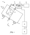
図1は、限定することを意図しておらず、本開示に記載された方法を使用してウェブ材料の均一性を特徴づけるのに好適なオンライン光学データ取得システムの実施形態を示す。システム10は、単に例示であり、本明細書に記載された画像処理アルゴリズムは、ウェブ材料の画像を捕捉するのに使用されるシステムとは概ね関係がないことが強調されるべきである。図1において、データ取得システム10は、ローラ14とローラ16との間を矢印Aの方向に移動しているウェブ材料12を含む。ウェブ材料12は、例えば、織布、不織布、紙、ポリマーフィルム、又は基材に塗布されたコーティング層から選択され得る。光源18は、ウェブ材料12を通して光を発し、ウェブ材料12における対象領域17を照射する。光源18は、例えば、赤外線又は紫外線等の可視範囲の外側の波長を含む、スペクトルの任意の好適な部分を使用して、対象領域17を画像化し得る。材料12を通過させた後、対象領域17の画像は、例えば、ラインスキャンカメラ等のカメラ20の配列により捕捉される。ただし、対象領域17の画像を捕捉するのに好適な任意のカメラ又は他の種類の検出器が使用されてもよい。対象領域の画像は、データ取得モジュール22に伝送され、次いで、コンピュータ24に伝送される。コンピュータ24は、ウェブ材料12が製造され、コーティングされ、又は、他の方法で処理される際に、カメラ20の配列により得られた画像をリアルタイムに処理することができるプロセッサを含む。対象領域17の画像処理からの結果は、ディスプレイ26上でユーザに対して表示され得る。
FIG. 1 is not intended to be limiting, but illustrates an embodiment of an on-line optical data acquisition system suitable for characterizing web material uniformity using the methods described in the present disclosure. It should be emphasized that the
図1では、ウェブ材料12は、後ろ側から照射され、一方、カメラ20は、ウェブ材料12の上から画像化する。これにより、カメラ20により画像化される前に、光がウェブ材料12を通過する。この種類のバックライト構成は、本明細書において透過モードでの画像化と呼ばれるが、ウェブの厚み又は開放性における不均一性を強調することができるため、一部の用途に有用である。透過モードで分析され得るウェブ材料としては、不織布又は透明若しくは半透明のポリマーフィルムが挙げられるが、これらに限定されない。
In FIG. 1, the
ウェブ材料がより高密度又はシート状である用途では、トップライト構成(top-light configuration)が使用されてもよい(図1において図示せず)。この場合、光源及びカメラは、ウェブ材料の同じ側にある。この種類のトップライト構成は、本明細書において反射モードでの画像化と呼ばれ、この場合、カメラは、ウェブ材料の表面から反射した光を画像化する。反射モードでの画像化は、織布材料又は光源により発せられた光の波長を容易に透過しない材料若しくはコーティングの分析により好適である場合がある。 In applications where the web material is more dense or sheet-like, top-light configurations may be used (not shown in FIG. 1). In this case, the light source and the camera are on the same side of the web material. This type of top light configuration is referred to herein as imaging in reflective mode, where the camera images light reflected from the surface of the web material. Imaging in the reflective mode may be more suitable for analysis of materials or coatings that do not readily transmit the wavelength of light emitted by the woven material or light source.
図2は、典型的には、不定の長さのものであり、方向Aに移動している、ウェブ材料112の均一性を評価するのに好適な光学照射システム110の側面図である。照射システム110は、少なくとも2つ、又は一部の実施形態では、3つの光源を含み、一部の実施形態では、少なくともいくつかの光源が視準されてもよい。直線光源118Aは、カメラ120の方向に光を発する。遠暗視野(Far dark field)光源118B及び118Cは、画像化カメラ120に対して、(それぞれ、α+β)の角度で光を発する。最も都合良く、直線光源118Aは、移動しているウェブ材料112の平面に対して、法線方向に照射するように位置付けられる。一部の実施形態では、光源118Aは、ファイバライトライン(fiber light line)、又は、ウェブ材料112の幅全体にわたるストリップを照射する蛍光灯である。このストリップをクロスウェブ方向に対して平行に向けると都合が良いが、このことが必須であるとは考えられない。
FIG. 2 is a side view of an
暗視野光源118B及び118Cは、ファイバライトラインとして都合良く提供されることもできるが、一部の実施形態では、レーザー光源又は他の光源が採用されてもよい。暗視野光源118B及び118Cは、クロスウェブ方向に沿った向きで、ウェブ材料112の幅全体にわたるストリップを都合よく照射する。ただし、一部の実施形態では、暗視野光源118B及び118Cは、ウェブ材料112の平面に対して法線方向の角度で取り付けられる。
The dark field
一部の実施形態では、レンズは、直線光源118A及び2つの暗視野光源118B、118Cから発せられた光を集束させるのに使用され得る。例えば、光源としてファイバライトラインが使用される場合、ファイバライトラインに対して平行な向きの円筒形レンズが使用されてもよい。円筒形レンズ132及び134は、好ましくは、遠暗視野光源118B及び118Cからの光を、カメラ120直下のライン上のウェブ112の下側に集束させる。直線光源118Aからの光を集束させる円筒形レンズ136は、円筒形レンズ132及び134と同じ焦点距離を有することができるが、直線光源11Aからの光は、拡散体138に向けられる。一実施形態において、拡散体138は、拡散フィルムである。拡散フィルム上のダークライン、又は例えば、拡散体138の真上に(又は上に)取り付けられた張られたケーブル若しくは細い金属片140などの別の固形物が、図2Aに示されたダークストライプを提供し得る。一部の実施形態では、ダークストライプ140は、好ましくは、非常に暗く、例えば、カーボンブラック色の絶縁材を有するケーブルを使用することにより、都合良く採用され得る。
In some embodiments, a lens may be used to focus the light emitted from linear
図3を参照すると、画像処理手順200は、カメラ20により捕捉され、取得モジュール22(図1)により取得された材料の対象領域の画像に適用されて、ウェブ材料12の対象領域17の均一性を特徴づけてもよい。
Referring to FIG. 3, the
一部の実施形態では、工程202においてカメラにより画像が取得された後で、更なる画像処理アルゴリズムが適用される前に、画像は、工程204において任意選択的に校正され、画像強度がその校正に基づいてマッピングされてもよい。図1におけるカメラにより得られた画像は、画素化形式での強度値であり、一部の実施形態では、これらの強度値が異なるレベルの光学透過について一定であるのが好ましい。均一性値は、測定された強度によるため、透過から画素強度への安定かつ繰り返し可能なマッピングを維持することは、所定の検査システムにおいて、かつ異なる検査システム間において、向上した正確性を経時的に提供し得る。
In some embodiments, after the image is acquired by the camera at
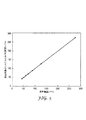
例えば、図2に記載されているようなダークストライプ照射検査システムについて、一部の実施形態では、強度校正は、校正パターンの画像を取得することに基づくことができる。例えば、拡散フィルム標準は、制御された方法でこの標準を透過した光量を変化させるために、異なる厚みの拡散フィルムの組み合わせを互いに重ね合わせることにより作製され得る。この校正標準の画像は、より厚い拡散フィルム層に対応する最も暗いストライプと、より薄い拡散フィルム層に対応する最も明るいストライプとを含む、一連の段階的なストライプとしてカメラに表れる。校正標準のこの画像は、カメラにより取得され、平面視野補正されることができ、図4に示されるような強度プロファイルは、校正パターンの各セクション内の平均グレースケールレベルを計算することにより抽出される。図4の強度プロファイルは、選択された光レベルについての標準における拡散フィルムの層数に対する強度レベルを示す。 For example, for the dark stripe illumination inspection system as described in FIG. 2, in some embodiments, the intensity calibration can be based on acquiring an image of the calibration pattern. For example, a diffusion film standard can be made by superimposing combinations of diffusion films of different thicknesses on one another in order to change the amount of light transmitted through this standard in a controlled manner. The image of this calibration standard appears to the camera as a series of graded stripes, including the darkest stripes corresponding to thicker diffuser film layers and the brightest stripes corresponding to thinner diffuser film layers. This image of the calibration standard can be acquired by the camera and planar field corrected, and an intensity profile as shown in FIG. 4 is extracted by calculating the average grayscale level within each section of the calibration pattern Ru. The intensity profile in FIG. 4 shows the intensity level versus the number of layers of diffuser film in the standard for the selected light level.
(いくつかの時点で検査システムにおいて抽出された)図4の強度プロファイルの1つは、基準プロファイルとして指定される。次いで、異なる時点での同じシステム又は完全に異なるシステムのいずれかである任意の他の強度プロファイルは、単純な線形射影により、この基準プロファイルにマッピングされ得る。すなわち、基準強度プロファイルは、
IB(L),L=1,2,...,N(式中、Nは、レベル数である。)により与えられ、
校正対象のシステムからの一部の他の強度プロファイルは、
I(L),L=1,2,...,N(式中、Nは、レベル数である。)により与えられる。
One of the intensity profiles of FIG. 4 (extracted at the inspection system at some point in time) is designated as the reference profile. Then, any other intensity profile that is either the same system or a completely different system at different points in time can be mapped to this reference profile by simple linear projection. That is, the reference intensity profile is
I B (L), L = 1, 2,. . . , N (where N is the number of levels),
Some other intensity profiles from the system to be calibrated are
I (L), L = 1, 2,. . . , N (where N is the number of levels).
次いで、 Then

IB(L)=mI(L)+b
I B (L) = mI (L) + b
線形マッピングは、図5の例に図示されるように、線形最少二乗回帰により取得される。 The linear mapping is obtained by linear least squares regression, as illustrated in the example of FIG.
任意選択的な画像校正工程204の後、画像処理技術が、材料における対象領域の全体的な均一性を、種々のサイズスケールs1,s2,...,snにおいて測定するのに適用されてもよい。サイズ範囲にわたる均一性の計算では、一部の不均一性は、小さいサイズスケールに存在するが、他のものは、より大きいサイズスケールにおいてのみ明らかとなる。特定用途の必要性に応じて、一部のサイズスケールでの均一性は、他のものより重要であると考えられる場合がある。例えば、材料を小さなパッチに変える用途では、これらのパッチよりはるかに大きいサイズスケールでの不均一性は、単一の小さなパッチの範囲内で見ることができないことから、表面上又は機能上の影響を何ら有さない場合がある。一方、より大きいスケールの不均一性は、サンプル間の機能的性質における差異を生じさせるおそれがある。これらは、均一性を推定するサイズスケールの範囲を選択する際に考慮され得る用途固有の考察の2つの例示となる類型である。
After an optional
再度図3を参照すると、工程206において、均一性を測定するサイズスケールのセットが、例えば、分析される材料の種類、最終製品のサイズ等に基づいて、最初に定義される。例えば、所定の用途について、操作者が、25mmと100mmとの間で25mmずつ増大させるスケールで均一性を特徴づけるのを望む場合がある。一部の実施形態では、このスケールは、段階的であることができ、この段階は、等しい、等しくない、又はランダムであってもよい。
Referring again to FIG. 3, in
図3の工程208において、所定のサイズスケールのそれぞれについて、プロセッサは、現在着目中のサイズスケールよりはるかに小さい不均一性の影響を除去及び/又は抑制するように、画像を処理する。この処理工程は、本明細書において一般的に、ローパスフィルタ処理と呼ばれ、一部の実施形態では、画像中の高周波数を抑制することができる。一部の実施形態では、プロセッサにより行われるローパスフィルタ処理工程は、平滑化に相当するが、フーリエ変換に関する周波数ドメインにおける理論的な解釈を有する。
At
一部の実施形態では、ローパスフィルタは、「ボックスフィルタ」であり、ボックスフィルタは、同一値からなる二次元カーネルからなる。画像に畳み込まれる場合、ボックスフィルタは、着目中のサイズスケールにおける各画素を、全ての隣接する画素値の平均に置き換える。他の実施形態では、二次元のガウスカーネルのローパスフィルタが使用されてもよく、同フィルタは、周波数ドメインにおけるより好ましい特徴を有し得る。画像に畳み込まれる場合、二次元のガウスカーネルは、各画素を、周囲画素の強度の荷重平均で置き換え、この場合、重量は、ガウスカーネルにより与えられる。 In some embodiments, the low pass filter is a "box filter" and the box filter consists of a two dimensional kernel of identical values. When folded into the image, the box filter replaces each pixel in the size scale of interest with the average of all adjacent pixel values. In other embodiments, a two-dimensional Gaussian kernel low pass filter may be used, which may have more favorable features in the frequency domain. When folded into the image, the two-dimensional Gaussian kernel replaces each pixel with a weighted average of the intensities of surrounding pixels, where the weight is given by the Gaussian kernel.
特定の用途のために選択されるローパスフィルタの種類に関わらず、アルゴリズムは、画像の高周波数成分を抑制する。同成分は、対象となるサイズスケールよりはるかに小さい画像特性からなる。ローパスフィルタは、対象となるサイズスケールにおおよそ近い不均一性のみの測定を可能にし、はるかに小さいサイズスケールにおける不均一性によって生じる所定のパッチにおける影響を除去する。より小さい不均一性は、マルチスケール処理アルゴリズムにおけるより小さいサイズスケールにおいて捕捉される。 Regardless of the type of low pass filter selected for a particular application, the algorithm suppresses high frequency components of the image. The component consists of image characteristics that are much smaller than the size scale of interest. The low pass filter allows measurement of only inhomogeneities that are approximately close to the size scale of interest, and eliminates the effects on a given patch caused by inhomogeneities on a much smaller size scale. Smaller inhomogeneities are captured at smaller size scales in multiscale processing algorithms.
ローパスフィルタの適用については、観察者がサンプルを物理的に見る際に、不均一性をどのように視覚的に認識するかという観点で考えられ得る。すなわち、観察者がサンプルに近づいて立った場合、表面の非常に微細な詳細が明らかとなるが、大きいスケールにおける全体的な均一性は明らかとならない。一方、観察者がサンプルから離れて立った場合、全体的な均一性及びバリエーションが画像を占めるが、観察者は、より小さいサイズスケールにおいて存在し得る微細レベルの詳細はもはや検出することができない。 The application of a low pass filter can be considered in terms of how to visually recognize inhomogeneities when the observer physically views the sample. That is, when the observer stands close to the sample, very fine details of the surface become apparent, but the overall uniformity on a large scale is not. On the other hand, when the observer stands away from the sample, the overall uniformity and variation dominate the image, but the observer can no longer detect the fine level of detail that may be present on the smaller size scale.
例えば、上記されたローパスフィルタ処理アルゴリズムの各反復において、ローパスフィルタは、均一性を測定する現在のサイズスケールの所定の比率に等しいカットオフ周波数を有するように選択され得る。具体的な一例において、着目中のサイズスケールが100画素に対応する場合、20画素の幅を有するボックスフィルタが、対象となるサイズスケールの外側の不均一性を抑制するのに選択される場合がある。 For example, in each iteration of the low pass filtering algorithm described above, the low pass filter may be selected to have a cutoff frequency equal to a predetermined ratio of the current size scale that measures uniformity. In a specific example, if the size scale of interest corresponds to 100 pixels, then a box filter having a width of 20 pixels may be selected to suppress non-uniformity outside of the size scale of interest. is there.
選択されたサイズスケールでの均一性分析に必須でない画像特性の影響を除去又は低減するために画像がフィルタされると、図3の工程210において、画像は、対象となるサイズスケールに等しい領域(本明細書において、パッチと呼ばれる)に分割される。画像は、不均一性を測定するための対象となる現在のサイズスケールに等しいサイズを有するパッチに分割される。その後に、不均一性の測定が、各パッチにおいて計算される。これにより、この分割は、より大きいサイズスケールにおける不均一性についての情報が捕捉されないことを確実にする効果を有する。より微細なサイズスケールにおける不均一性が、前の工程におけるローパスフィルタ処理により抑制される。
Once the image has been filtered to remove or reduce the effects of image characteristics that are not essential for uniformity analysis at the selected size scale, in
図3における工程212を参照すると、各パッチの不均一性を算出するために、プロセッサは、定量的及び繰り返し可能な方法において、パッチの画像の全体的な均一性を特徴づける測定法を適用する。まず、小さなサブ画像が、2つの変数I(x,y)の関数であると考えられ得る。この場合、x及びyは、画素位置の指標であり、I(x,y)は、位置(x,y)における画素の強度である。この定義から、単純な統計学的計算が、サブ画像における均一性(又は(非)均一性)のためのプロキシとして使用され得る。例えば、多くの場合において、完全に均一なパッチは、全ての強度値が等しいものであるため、パッチの標準偏差は、測定法について1つの単純な選択である。パッチI(x,y)とすると、サンプルの標準偏差は、下記のように計算され得る。 Referring to step 212 in FIG. 3, to calculate the non-uniformity of each patch, the processor applies a measurement that characterizes the overall uniformity of the image of the patch in a quantitative and repeatable manner . First, a small sub-image can be considered to be a function of two variables I (x, y). In this case, x and y are indices of the pixel position, and I (x, y) is the intensity of the pixel at position (x, y). From this definition, simple statistical calculations can be used as a proxy for uniformity (or (non) uniformity) in sub-images. For example, in many cases, a patch's standard deviation is one simple choice for the measurement method, as a perfectly uniform patch is one where all intensity values are equal. Given patch I (x, y), the standard deviation of the sample can be calculated as follows.
他の可能な均一性測定法としては、四分位範囲(IQR)、中央絶対偏差(MAD)、及び情報エントロピー等が挙げられる。一部の実施形態では、IQRは、サンプル領域中の第75百分位数の強度値と第25百分位数の強度値との間の差異として定義され、外れ値に対してより頑強である。 Other possible uniformity measures include interquartile range (IQR), median absolute deviation (MAD), and information entropy etc. In some embodiments, IQR is defined as the difference between the 75th percentile and 25th percentile intensity values in the sample region, and is more robust against outliers. is there.
この均一性分析は、新たな画像がカメラ20及び取得モジュール22(図1)により取得されるたび、測定法を使用して各パッチについて計算される。一部の実施形態では、図3の工程214において、分析コンピュータ24中のプロセッサは、更なる計算又は分析を任意選択的に行って、パッチにおける不均一性値を統合し得る。例えば、一部の実施形態では、パッチの均一性値は、対象領域についての全体的な均一性値を決定するのに統合される。一部の非限定的な実施形態では、例えば、パッチの均一性値は、平均、中央、標準偏差等を使用して統合され得る。別の例では、対象領域内のパッチの選択された配列の均一性値は、対象領域についての均一性値を提供するのに統合され得る。
This uniformity analysis is calculated for each patch using the measurement method as new images are acquired by the
工程215において、画像処理工程208,210,212,214は、サイズスケールs1,s2,...,sn毎に繰り返される。
In
一部の実施形態では、図3の工程216に示されるように、均一性値は、サイズスケールに対する均一性のプロットとして、ディスプレイ26(図1)上に表示され得る。これは、この設定の目的が、異なる材料又は配合を比較することであり得るため、処理がオフラインで行われる場合に都合が良い。ただし、本開示の画像処理技術が製造ラインにおけるリアルタイム検査のためにオンラインで使用されることを意味する場合には、対象となるいくつかの異なるサイズスケールについての個々の曲線を示す、時間に対する均一性のプロットを表示するのがより有益である場合がある。オンライン処理について、これにより、生産稼働中又は稼働間中における均一性の経時的変化の制御表形式による可視化が可能となる。
In some embodiments, as shown in
図1及び図2に示される光学検査システムは、ウェブ製造工場内で使用されて、ウェブ材料中の不均一性欠陥の存在を検出するために、図3の手順を適用してもよい。検査システムは、ウェブが製造される際リアルタイムに、各欠陥の重大度を示す出力データも提供し得る。例えば、コンピュータ化検査システムは、ウェブ製造プラント内のプロセスエンジニアなどのユーザに、不均一性の存在及びその重大度に関するリアルタイムのフィードバックを提供してもよい。これにより、ユーザは、プロセス条件を調節することにより不均一性の発生に素早く対応することができ、製造を著しく遅延させることなく、又は、使用に適さない材料を大量に製造することなく、問題を修正できる。コンピュータ化検査システムは、アルゴリズムを適用して、不均一性についての格付けラベル(例えば、「良い」又は「悪い」)を最終的に割り当てることにより、又は、連続スケール若しくはより正確にサンプリングされたスケールで、所定サンプルの不均一性の重大度の測定を生成することにより、重大度レベルを計算することができる。 The optical inspection system shown in FIGS. 1 and 2 may be used in a web manufacturing plant to apply the procedure of FIG. 3 to detect the presence of non-uniform defects in web material. The inspection system may also provide output data indicating the severity of each defect in real time as the web is manufactured. For example, a computerized inspection system may provide a user, such as a process engineer in a web manufacturing plant, with real-time feedback regarding the presence of the non-uniformity and its severity. This allows the user to react quickly to the occurrence of inhomogeneities by adjusting the process conditions, without significantly delaying production or without producing a large amount of material unsuitable for use. You can correct The computerized inspection system applies an algorithm to finally assign a rating label (eg, "good" or "bad") for heterogeneity, or a continuous scale or a scale more accurately sampled The severity level can then be calculated by generating a measure of the severity of the non-uniformity of a given sample.
分析コンピュータ24(図1)は、ウェブ用のロール識別情報、及び場合により、対象となる各測定領域17についての位置情報を含む、ウェブ材料12についての特性的寸法情報を、データベース25に記憶してもよい。例えば、分析コンピュータ24は、基準マーク制御部により生成される位置データを利用して、プロセスラインの座標系内の各測定された特性の空間的位置又は画像領域を決定してもよい。すなわち、基準マーク制御部からの位置データに基づいて、分析コンピュータ24は、現在のプロセスラインにより使用される座標系内の対象となる各測定領域17についての、x、y、及び場合により、z位置又は範囲を決定する。例えば、座標系は、x寸法がウェブを横切る距離を表し、y寸法がウェブの長さに沿った距離を表し、z寸法がウェブの高さを表すように画定されてもよい。これらは、コーティング、材料、又はウェブに事前に適用された他の層の数に基づいていてもよい。更に、x、y、z座標系の原点は、プロセスライン内の物理的位置に画定されてもよく、典型的には、ウェブ12の初期供給配置(initial feed placement)に関連付けられる。
The analysis computer 24 (FIG. 1) stores in the
データベース25は、データ格納ファイル、又は1つ若しくは2つ以上のデータベースサーバ上で実行される1つ若しくは2つ以上のデータベース管理システム(DBMS)を含む、数多くの異なる形態のいずれかにおいて実行されてもよい。データベース管理システムは、例えば、リレーショナル(RDBMS)、階層型(HDBMS)、多次元(MDBMS)、オブジェクト指向型(ODBMS又はOODBMS)、又はオブジェクト・リレーショナル(ORDBMS)データベース管理システムでもよい。一例として、データベース25は、Microsoft Corporation(Redmond,WA)より商品名SQL Serverで入手可能なリレーショナルデータベースとして実行される。
The
処理が終了すると、分析コンピュータ24は、データベース25に収集されたデータを、ネットワーク50を介して、変換制御システム60に送信してもよい。例えば、分析コンピュータ24は、ロール情報並びに均一性情報及び各均一性測定用の各サブ画像を、後続するオフラインでの詳細分析のために、変換制御システム60に伝達してもよい。例えば、均一性情報は、データベース25と変換制御システム60との間のデータベース同期により伝達されてもよい。
When the processing is completed, the
一部の実施形態では、分析コンピュータ24ではなく、変換制御システム60が、各異常が欠陥を起こすであろう製品中のそれらの製品を決定してもよい。完成したウェブロール用のデータがデータベース25に収集されると、このデータは、変換現場に伝達されてもよく、かつ/又は、取り外し可能若しくは洗浄可能なマークによりウェブの表面に直接マークを付けるか、或いは、ウェブ上の異常にマークを付ける前、若しくはその最中にウェブに適用され得るカバーシート上に直接マークを付けるか、のいずれかによって、ウェブロール上の異常にマークを付けるために使用されてもよい。
In some embodiments, conversion control system 60, rather than
分析コンピュータ24の構成要素は、1つ又は2つ以上のハードウェアマイクロプロセッサ、デジタル信号プロセッサ(DSP)、特定用途向け集積回路(ASIC)、フィールドプログラマブルゲートアレイ(FPGA)、又は任意の他の同等の統合論理回路若しくは個別論理回路、並びにかかる構成要素の任意の組み合わせを含む、分析コンピュータ24の1つ又は2つ以上のプロセッサによって実行されるソフトウェア命令として、少なくとも部分的に、実行されてもよい。ソフトウェア命令は、ランダムアクセスメモリ(RAM)、読み出し専用メモリ(ROM)、プログラマブル読み出し専用メモリ(PROM)、消去可能プログラマブル読み出し専用メモリ(EPROM)、電気的消去可能プログラマブル読み出し専用メモリ(EEPROM)、フラッシュメモリ、ハードディスク、CD−ROM、フロッピーディスク、カセット、磁気媒体、光媒体、又は他のコンピュータ可読記憶媒体を含む、非一時的なコンピュータ可読媒体に記憶されてよい。
The components of
製造工場内に位置付けられるものとしての例の目的で示されているが、分析コンピュータ24は、製造プラントの外部、例えば、中心部又は変換現場に位置していてもよい。例えば、分析コンピュータ24は、変換制御システム60内で動作してもよい。別の例では、上述の構成要素は、単一の計算プラットホーム上で実行し、同じソフトウェアシステムに組み込まれてもよい。
Although shown for purposes of example as being located within a manufacturing plant,
本開示の主題を、以下の非限定的な実施例を参照して、説明する。 The subject matter of the present disclosure will be described with reference to the following non-limiting examples.
図1及び図2に概ね示された暗視野画像化システムを準備し、不織布ウェブ材料の均一性を、製造ラインにおいて不織布ウェブ材料が製造される際にリアルタイムに測定するのに使用した。均一性検査を行う前に、画像化システムを、上記のように校正した。より具体的には、校正パターンは、10%〜90%での透過の範囲での10のレベルであった。透過を調節するために、幅10μm〜90μmの範囲の微細な線で印刷されたフィルムを使用して、校正パターンを構築した。General Electric(Fairfield,CT)からILLUMINEXとして市販されている拡散フィルムの層も使用した。これらの層を、金属フレーム上に共に取り付けた。 A dark field imaging system, shown generally in FIGS. 1 and 2, was prepared and used to measure the uniformity of the non-woven web material in real time as the non-woven web material was produced in a production line. Prior to performing the uniformity check, the imaging system was calibrated as described above. More specifically, the calibration pattern was at a level of 10 in the range of 10% to 90% transmission. A calibration pattern was constructed using a fine line printed film in the range of 10 [mu] m to 90 [mu] m wide to control transmission. A layer of diffusion film commercially available as ILLUMINEX from General Electric (Fairfield, Conn.) Was also used. The layers were mounted together on a metal frame.
従来のエアレイド法を使用して、ポリマーの撚糸から不織布ウェブ材料を形成した。同不織布ウェブ材料は、おおよそ1.25cmの平均厚みを有し、更に厚みに著しい変化、例えば、極めて接近して相対的に薄い部分と厚い部分とを有する。 Nonwoven web materials were formed from polymeric yarns using conventional air laid methods. The same nonwoven web material has an average thickness of approximately 1.25 cm, and also has significant changes in thickness, eg, relatively thin portions and relatively thick portions in close proximity.
ウェブ表面からおおよそ10cm下に光源を配置し、そのおおよそ102cm上に、カメラを配置した。図2に記載の通り、ダークストライプ照射を使用した。この場合、ダークストライプは、おおよそ5mm幅とした。画像化光学系を、240μmのクロスウェブ解像を達成するように構成した。E2V(Chelmsford,UK)からAVIIVA EM2として市販されているラインスキャンカメラを、焦点距離40mmの画像化レンズと共に使用した。光源を、Pro Photonics(Salem,NH)からCOBRA SLIMとして市販されているLED系ラインライトとした。試験運転中、不織布ウェブを、12.2m/分のライン速度で搬送して、検査システムを通過させた。Minarik Automation and Control(Eagan,MN)からDYNAPARとして市販されているエンコーダホイールを、ウェブの並進移動をエンコードするのに使用した。これにより、電気パルスを、ウェブの並進移動に対して、一定速度で発生させた。 The light source was placed approximately 10 cm below the web surface, and the camera was placed approximately 102 cm above it. Dark stripe illumination was used as described in FIG. In this case, the dark stripe is approximately 5 mm wide. The imaging optics were configured to achieve a cross web resolution of 240 μm. A line scan camera commercially available as AVIIVA EM2 from E2V (Chelmsford, UK) was used with an imaging lens with a focal length of 40 mm. The light source was an LED based line light commercially available as COBRA SLIM from Pro Photonics (Salem, NH). During the test run, the nonwoven web was conveyed at a line speed of 12.2 m / min through the inspection system. An encoder wheel commercially available as DYNAPAR from Minarik Automation and Control (Eagan, Minn.) Was used to encode translational movement of the web. This generated an electrical pulse at a constant velocity relative to the translational movement of the web.
製造ラインを稼働させ、ウェブを搬送しながら、ダウンウェブ方向に沿って一定の間隔のクロスウェブ画像ラインを、画像化システムにより取得した。これらのラインは、互いに重ね合わせられた際に、二次元画像を形成した。次いで、これらの画像を、上記されたマルチスケール均一性アルゴリズムに基づいて処理した。 While the production line was up and transporting the web, cross-web image lines at regular intervals along the down web direction were acquired by the imaging system. These lines formed a two dimensional image when superimposed on one another. These images were then processed based on the multiscale uniformity algorithm described above.
この場合において、不均一性を、対象となる5種類のサイズスケールで測定した。これらを、10mm,25mm,50mm,75mm、及び100mmとした。各画像について、不均一性についての1回の測定を、各サイズスケールについて計算した。これらを、5つのサイズスケールのそれぞれで表示した時間に対する不均一性について、時系列プロットとして表示した。これにより、5種類の曲線がプロットでもたらされる。この方法で得られたプロットの例を、図6に示す。 In this case, non-uniformity was measured on five different size scales of interest. These were made into 10 mm, 25 mm, 50 mm, 75 mm, and 100 mm. For each image, one measurement for inhomogeneity was calculated for each size scale. These were displayed as time series plots for the heterogeneity versus time indicated on each of the five size scales. This gives five curves in a plot. An example of a plot obtained by this method is shown in FIG.
本発明の種々の実施形態について説明した。これら及び他の実施形態は、下記特許請求の範囲の範囲内である。
本発明の実施態様の一部を以下の〔態様1〕−〔態様60〕に記載する。
〔態様1〕
材料の均一性を特徴づける方法であって、
該材料の画像中の対象領域内の均一性を測定するサイズスケールのセットを選択することと、
該サイズスケールのセット内の対象となる選択されたサイズスケールより小さい該画像中の特性を抑制することと、
該対象となるサイズスケールに等しいパッチに該画像を分割することと、
各パッチ内の均一性値を算出することと、を含む、方法。
〔態様2〕
前記特性を抑制することが、ローパスフィルタで前記画像を処理することを含む、態様1に記載の方法。
〔態様3〕
前記ローパスフィルタが、前記対象となるサイズスケールの所定の比率に等しいカットオフ周波数を有するボックスフィルタを含む、態様2に記載の方法。
〔態様4〕
前記ローパスフィルタが、二次元のガウスカーネルを含む、態様2に記載の方法。
〔態様5〕
前記均一性値が、前記パッチの選択された特徴の標準偏差、四分位範囲(IQR)、中央絶対偏差、又は情報エントロピーのうち少なくとも1つを決定することにより算出される、態様1〜4のいずれか一項に記載の方法。
〔態様6〕
前記パッチの前記選択された特徴が、前記パッチを透過した光又は前記パッチを含む前記材料の表面から反射した光の強度を含む、態様5に記載の方法。
〔態様7〕
前記均一性値が、前記パッチを透過した前記光の強度の前記四分位範囲(IQR)を決定することにより算出される、態様5に記載の方法。
〔態様8〕
前記特性を除去する前に、前記対象領域を所定のサイズに拡大縮小することを更に含む、態様1〜7のいずれか一項に記載の方法。
〔態様9〕
前記特性を除去する前に、前記対象領域を校正することを更に含む、態様1〜8のいずれか一項に記載の方法。
〔態様10〕
前記パッチの前記均一性値を統合して、前記対象領域についての均一性値を決定することを更に含む、態様1〜8のいずれか一項に記載の方法。
〔態様11〕
前記対象領域内のパッチの選択された配列の前記均一性値を統合して、前記対象領域についての均一性値を提供することを更に含む、態様1〜10のいずれか一項に記載の方法。
〔態様12〕
前記材料が、織布、不織布、紙、コーティング、ポリマーフィルム、及びそれらの組み合わせから選択される、態様1〜11のいずれか一項に記載の方法。
〔態様13〕
前記材料が、不織布である、態様12に記載の方法。
〔態様14〕
前記対象領域を含む前記材料の表面に光を透過させることにより、又は該表面から光を反射させることにより、前記画像が得られる、態様1〜13のいずれか一項に記載の方法。
〔態様15〕
前記材料から光受信装置に向かって光を透過させることにより、前記画像が得られる、態様14に記載の方法。
〔態様16〕
材料の均一性を特徴づける方法であって、
該材料から光受信装置に向かって光を透過させることにより、該材料の対象領域の画像を得ることと、
該対象領域内の均一性を測定する段階的なサイズスケールのセットを選択することと、
ローパスフィルタを画像に畳み込みして、該段階的なサイズスケールのセット内の対象となる選択されたサイズスケールより小さい該画像中の特性を抑制することと、
該対象となるサイズスケールに等しいパッチに該画像を分割することであって、該パッチがそれぞれ画素配列を含む、ことと、
該配列における該画素の該光強度の標準偏差を決定して、各パッチ内の均一性値を算出することと、を含む、方法。
〔態様17〕
前記ローパスフィルタが、前記配列内の前記画素の所定の比率に等しい幅を有するボックスフィルタを含む、態様16に記載の方法。
〔態様18〕
前記ローパスフィルタが、前記配列における選択された画素を、該選択された画素を取り囲む前記画素の前記光強度の加重平均で置き換え、該加重平均が、二次元のガウスカーネルにより決定される、態様17に記載の方法。
〔態様19〕
選択された不均一性を分析するのに理想的な画素サイズを決定することと、前記特性を除去する前に、前記対象領域を該理想的な画素サイズに拡大縮小することと、を更に含む、態様16〜18のいずれか一項に記載の方法。
〔態様20〕
前記特性を除去する前に、前記対象領域を校正することを更に含む、態様16〜19のいずれか一項に記載の方法。
〔態様21〕
前記パッチの前記均一性値を統合して、前記対象領域についての均一性値を決定することを更に含む、態様16〜20のいずれか一項に記載の方法。
〔態様22〕
前記対象領域内のパッチの選択された配列の前記均一性値を統合して、前記対象領域についての均一性値を提供することを更に含む、態様16〜21のいずれか一項に記載の方法。
〔態様23〕
前記材料が、織布、不織布、紙、コーティング、ポリマーフィルム、及びそれらの組み合わせから選択される、態様16〜22のいずれか一項に記載の方法。
〔態様24〕
前記材料が、不織布である、態様24に記載の方法。
〔態様25〕
装置であって、
材料のウェブを照射する少なくとも1つの光源と、
該材料における対象領域を透過した光又は該対象領域から反射した光を捕捉して、該対象領域の画像を生成するカメラと、
プロセッサであって、該対象領域内の均一性を測定するサイズスケールのセットの入力に応じて、
ローパスフィルタを該画像に畳み込みして、該サイズスケールのセット内の対象となる選択されたサイズスケールより小さい該画像中の特性を抑制することと、
該対象となるサイズスケールに等しいパッチに該画像を分割することであって、該パッチがそれぞれ画素配列を含む、ことと、
各パッチ内の均一性値を算出することと、を行う、プロセッサと、を備える、装置。
〔態様26〕
前記プロセッサが、前記配列における前記画素の光強度の標準偏差、四分位範囲(IQR)、中央絶対偏差、又は情報エントロピーのうち少なくとも1つを決定することにより、前記均一性値を算出する、態様25に記載の装置。
〔態様27〕
前記プロセッサが、前記四分位範囲(IQR)を決定することにより、前記均一性値を算出する、態様25又は26に記載の装置。
〔態様28〕
前記ローパスフィルタが、前記配列内の前記画素の所定の比率に等しい幅を有するボックスフィルタを含む、態様25〜27のいずれか一項に記載の装置。
〔態様29〕
前記ローパスフィルタが、前記配列における選択された画素を、該選択された画素を取り囲む前記画素の前記光強度の加重平均で置き換え、該加重平均が、二次元のガウスカーネルにより決定される、態様25〜27のいずれか一項に記載の装置。
〔態様30〕
前記プロセッサが更に、前記材料中の選択された不均一性を分析するのに理想的な画素サイズを決定し、かつ前記特性を除去する前に、前記対象領域を該理想的な画素サイズに拡大縮小する、態様25〜29のいずれか一項に記載の装置。
〔態様31〕
前記プロセッサが、前記特性を除去する前に、前記対象領域を校正する、態様25〜30のいずれか一項に記載の装置。
〔態様32〕
前記プロセッサが、前記パッチの前記均一性値を統合して、前記対象領域についての均一性値を決定する、態様25〜31のいずれか一項に記載の装置。
〔態様33〕
前記プロセッサが、前記対象領域内のパッチの選択された配列の前記均一性値を統合して、前記対象領域についての均一性値を提供する、態様25〜32のいずれか一項に記載の装置。
〔態様34〕
前記材料が、不織布及びポリマーフィルムから選択される、態様25〜33のいずれか一項に記載の装置。
〔態様35〕
前記材料が、不織布である、態様34に記載の装置。
〔態様36〕
前記カメラが、前記対象領域を透過した光を捕捉する、態様25〜35のいずれか一項に記載の装置。
〔態様37〕
前記カメラが、散乱した光のみを捕捉して、前記画像を形成する、態様36に記載の装置。
〔態様38〕
ダークストライプが、前記光源を横切って配置され、前記カメラが、該ダークストライプに真っ直ぐに向けられる、態様36に記載の装置。
〔態様39〕
ウェブ材料が製造される際、リアルタイムに該ウェブ材料を検査し、かつ該ウェブ材料の表面における対象領域の均一性レベルを計算する方法であって、
該材料から光受信装置に向かって光を透過させることにより、該対象領域の画像を得ることと、
該対象領域内の均一性を測定するサイズスケールのセットを選択することと、
ローパスフィルタを該画像に畳み込みして、該サイズスケールのセット内の対象となる選択されたサイズスケールより小さい該画像中の特性を抑制することと、
該対象となるサイズスケールに等しいパッチに該画像を分割することであって、該パッチがそれぞれ画素配列を含む、ことと、
各パッチ内の均一性値を算出することと、を含む、方法。
〔態様40〕
前記均一性値が、前記配列における前記画素の前記光強度の前記四分範囲(IQR)を決定することにより算出される、態様39に記載の方法。
〔態様41〕
前記ローパスフィルタが、前記配列内の前記画素の所定の比率に等しい幅を有するボックスフィルタを含む、態様39又は40に記載の方法。
〔態様42〕
前記ローパスフィルタが、前記配列における選択された画素を、該選択された画素を取り囲む前記画素の前記光強度の加重平均で置き換え、該加重平均が、二次元のガウスカーネルにより決定される、態様39又は40に記載の方法。
〔態様43〕
選択された不均一性を分析するのに理想的な画素サイズを決定することと、前記特性を除去する前に、前記対象領域を該理想的な画素サイズに拡大縮小することと、を更に含む、態様39〜42のいずれか一項に記載の方法。
〔態様44〕
前記特性を除去する前に、前記対象領域を校正することを更に含む、態様39〜43のいずれか一項に記載の方法。
〔態様45〕
前記パッチの前記均一性値を統合して、前記対象領域についての均一性値を決定することを更に含む、態様39〜44のいずれか一項に記載の方法。
〔態様46〕
前記対象領域内のパッチの選択された配列の前記均一性値を統合して、前記対象領域についての均一性値を提供することを更に含む、態様39〜45のいずれか一項に記載の方法。
〔態様47〕
前記材料が、不織布である、態様39〜46のいずれか一項に記載の方法。
〔態様48〕
リアルタイムにウェブ材料を検査するためのオンラインコンピュータ化検査システムであって、該システムが、
材料のウェブを照射する少なくとも1つの光源と、
該材料における対象領域を透過した光又は該対象領域から反射した光を捕捉して、該対象領域の画像を生成するカメラと、
該対象領域における該材料の均一性を特徴づけるソフトウェアを実行するコンピュータであって、該コンピュータが、プロセッサであって、該対象領域内の均一性を測定するサイズスケールのセットの入力に応じて、
ローパスフィルタを該画像に畳み込みして、該サイズスケールのセット内の対象となる選択されたサイズスケールより小さい該画像中の特性を抑制することと、
該対象となるサイズスケールに等しいパッチに該画像を分割することであって、該パッチがそれぞれ画素配列含む、ことと、
各パッチ内の均一性値を算出することと、を行う、プロセッサを含む、コンピュータと、を含む、システム。
〔態様49〕
ウェブ検査モデルを記憶するメモリを更に備え、前記コンピュータが、前記対象領域における前記均一性を該モデルと比較し、かつ前記材料中の不均一性欠陥の重大度を計算するソフトウェアを実行する、態様48に記載のシステム。
〔態様50〕
前記欠陥の前記重大度をユーザに出力するユーザインターフェイスを更に備える、態様48又は49に記載のシステム。
〔態様51〕
前記材料が、不織布である、態様48〜50のいずれか一項に記載のシステム。
〔態様52〕
オンラインコンピュータ化検査システムを使用して、ウェブ材料の表面における1つ又は2つ以上の対象領域の画像をその製造中に受信させることと、
該対象領域内の均一性を測定するサイズスケールのセットを選択させることと、
ローパスフィルタを該画像に畳み込みして、該サイズスケールのセット内の対象となる選択されたサイズスケールより小さい該画像中の特性を抑制させることと、
該対象となるサイズスケールに等しいパッチに該画像を分割させることであって、該パッチがそれぞれ画素配列を含む、ことと、
各パッチ内の均一性値を計算させることと、をコンピュータプロセッサに行わせるソフトウェア命令を含む、非一時的なコンピュータ可読媒体。
〔態様53〕
前記均一性値が、前記配列における前記画素の前記光強度の前記四分範囲(IQR)を決定することにより算出される、態様52に記載のコンピュータ可読媒体。
〔態様54〕
前記ローパスフィルタが、前記配列内の前記画素の所定の比率に等しい幅を有するボックスフィルタを含む、態様52又は53に記載のコンピュータ可読媒体。
〔態様55〕
前記ローパスフィルタが、前記配列における選択された画素を、該選択された画素を取り囲む前記画素の前記光強度の加重平均で置き換え、該加重平均が、二次元のガウスカーネルにより決定される、態様52又は53に記載のコンピュータ可読媒体。
〔態様56〕
前記プロセッサが更に、選択された不均一性を分析するのに理想的な画素サイズを決定し、かつ前記特性を除去する前に、前記対象領域を該理想的な画素サイズに拡大縮小する、態様52〜55のいずれか一項に記載のコンピュータ可読媒体。
〔態様57〕
前記プロセッサが、前記特性を除去する前に、前記対象領域を校正する、態様52〜56のいずれか一項に記載のコンピュータ可読媒体。
〔態様58〕
前記プロセッサが、前記パッチの前記均一性値を統合して、前記対象領域についての均一性値を決定する、態様52〜57のいずれか一項に記載のコンピュータ可読媒体。
〔態様59〕
前記プロセッサが、前記対象領域内のパッチの選択された配列の前記均一性値を統合して、前記対象領域についての均一性値を提供する、態様52〜58のいずれか一項に記載のコンピュータ可読媒体。
〔態様60〕
前記材料が、不織布である、態様52〜59のいずれか一項に記載のコンピュータ可読媒体。
Various embodiments of the present invention have been described. These and other embodiments are within the scope of the following claims.
Some of the embodiments of the present invention are described in the following [Aspect 1]-[Aspect 60].
[Aspect 1]
A method of characterizing the uniformity of materials,
Selecting a set of size scales to measure uniformity within a region of interest in an image of the material;
Suppressing features in the image that are smaller than a selected size scale of interest within the set of size scales;
Dividing the image into patches equal to the target size scale;
Calculating uniformity values within each patch.
[Aspect 2]
The method according to
[Aspect 3]
[Aspect 4]
The method according to
[Aspect 5]
Aspects 1-4, wherein the uniformity value is calculated by determining at least one of a standard deviation, an interquartile range (IQR), a central absolute deviation, or an informational entropy of selected features of the patch. The method according to any one of the preceding claims.
[Aspect 6]
6. The method according to
The method according to
[Aspect 8]
[Aspect 9]
Aspect 9. The method according to any one of aspects 1-8, further comprising calibrating the region of interest prior to removing the characteristic.
[Aspect 10]
Aspect 11. The method according to any one of aspects 1-8, further comprising combining the uniformity values of the patch to determine a uniformity value for the region of interest.
[Aspect 11]
Aspect 11. The method according to any one of aspects 1-10, further comprising combining the uniformity values of selected sequences of patches in the region of interest to provide uniformity values for the region of interest. .
[Aspect 12]
12. The method according to any one of aspects 1-11, wherein the material is selected from woven fabric, non-woven fabric, paper, coatings, polymer films, and combinations thereof.
[Aspect 13]
Aspect 13. The method according to
[Aspect 14]
14. A method according to any of the preceding aspects, wherein the image is obtained by transmitting light to the surface of the material comprising the area of interest or by reflecting light from the surface.
Aspect 15
15. A method according to
A method of characterizing the uniformity of materials,
Obtaining an image of a region of interest of the material by transmitting light from the material towards the light receiving device;
Selecting a set of graded size scales to measure uniformity within the region of interest;
Convolving a low pass filter into the image to suppress features in the image that are smaller than a selected size scale of interest within the set of graded size scales;
Dividing the image into patches equal to the target size scale, the patches each comprising an array of pixels;
Determining the standard deviation of the light intensity of the pixels in the array to calculate a uniformity value within each patch.
17. The method according to
[Aspect 18]
The low pass filter replaces the selected pixel in the array with a weighted average of the light intensities of the pixels surrounding the selected pixel, the weighted average being determined by a two dimensional Gaussian kernel The method described in.
Aspect 19
The method further includes determining an ideal pixel size for analyzing the selected non-uniformity, and scaling the region of interest to the ideal pixel size before removing the characteristic. 20. The method according to any one of aspects 16-18.
[Aspect 20]
20. A method according to any one of aspects 16-19, further comprising calibrating the region of interest prior to removing the characteristic.
[Aspect 21]
Aspect 21. The method according to any one of aspects 16-20, further comprising combining the uniformity values of the patch to determine a uniformity value for the region of interest.
[Aspect 22]
22. The method according to any one of aspects 16-21, further comprising combining the uniformity values of selected sequences of patches in the region of interest to provide uniformity values for the region of interest. .
[Aspect 23]
23. The method according to any one of aspects 16-22, wherein the material is selected from woven fabric, non-woven fabric, paper, coatings, polymer films, and combinations thereof.
[Aspect 24]
The method according to
[Aspect 25]
A device,
At least one light source illuminating the web of material;
A camera for capturing light transmitted through a target area of the material or light reflected from the target area to generate an image of the target area;
A processor responsive to the input of a set of size scales measuring uniformity within the region of interest;
Convoluting a low pass filter to the image to suppress features in the image that are smaller than a selected size scale of interest within the set of size scales;
Dividing the image into patches equal to the target size scale, the patches each comprising an array of pixels;
A processor for calculating uniformity values within each patch.
[Aspect 26]
The processor calculates the uniformity value by determining at least one of a standard deviation, an interquartile range (IQR), a central absolute deviation, or an information entropy of light intensities of the pixels in the array; The device according to
Aspect 27
26. The apparatus according to
[Aspect 28]
26. The apparatus according to any one of aspects 25-27, wherein the low pass filter comprises a box filter having a width equal to a predetermined ratio of the pixels in the array.
[Aspect 29]
25. The low-pass filter replaces a selected pixel in the array with a weighted average of the light intensities of the pixels surrounding the selected pixel, the weighted average being determined by a two-dimensional Gaussian kernel A device according to any one of 27 to 27.
[Aspect 30]
The processor further determines an ideal pixel size for analyzing selected non-uniformities in the material, and expands the region of interest to the ideal pixel size before removing the property. 30. The apparatus according to any one of aspects 25-29, which reduces.
Aspect 31
31. The apparatus according to any one of aspects 25-30, wherein the processor calibrates the region of interest prior to removing the characteristic.
Embodiment 32
32. The apparatus as in any one of aspects 25-31, wherein the processor integrates the uniformity values of the patches to determine a uniformity value for the region of interest.
[Aspect 33]
Aspect 32. The apparatus according to any one of aspects 25-32, wherein the processor integrates the uniformity values of a selected array of patches in the region of interest to provide a uniformity value for the region of interest. .
[Aspect 34]
34. The apparatus according to any one of aspects 25-33, wherein the material is selected from non-woven and polymeric films.
[Aspect 35]
35. The device according to aspect 34, wherein the material is a non-woven.
[Aspect 36]
Aspect 34. The apparatus according to any one of aspects 25-35, wherein the camera captures light transmitted through the region of interest.
[Aspect 37]
37. The apparatus according to aspect 36, wherein the camera captures only scattered light to form the image.
[Aspect 38]
37. The apparatus according to aspect 36, wherein a dark stripe is disposed across the light source and the camera is directed straight to the dark stripe.
Aspect 39
A method of inspecting the web material in real time as the web material is being manufactured and calculating the level of uniformity of the area of interest on the surface of the web material,
Obtaining an image of the region of interest by transmitting light from the material towards the light receiving device;
Selecting a set of size scales to measure uniformity within the region of interest;
Convoluting a low pass filter to the image to suppress features in the image that are smaller than a selected size scale of interest within the set of size scales;
Dividing the image into patches equal to the target size scale, the patches each comprising an array of pixels;
Calculating uniformity values within each patch.
[Aspect 40]
40. The method according to aspect 39, wherein the uniformity value is calculated by determining the quadrant of the light intensity (IQR) of the pixels in the array.
Aspect 41
Method according to aspect 39 or 40, wherein the low pass filter comprises a box filter having a width equal to a predetermined proportion of the pixels in the array.
[Aspect 42]
The low pass filter replacing the selected pixel in the array with a weighted average of the light intensities of the pixels surrounding the selected pixel, the weighted average being determined by a two-dimensional Gaussian kernel Or the method according to 40.
[Aspect 43]
The method further includes determining an ideal pixel size for analyzing the selected non-uniformity, and scaling the region of interest to the ideal pixel size before removing the characteristic. , A method according to any one of aspects 39-42.
[Aspect 44]
44. The method according to any one of aspects 39-43, further comprising calibrating the region of interest prior to removing the characteristic.
[Aspect 45]
Aspect 43. The method of any one of aspects 39-44, further comprising combining the uniformity values of the patch to determine a uniformity value for the region of interest.
[Aspect 46]
Aspect 43. The method according to any one of aspects 39-45, further comprising combining the uniformity values of selected sequences of patches in the region of interest to provide uniformity values for the region of interest. .
Aspect 47
Aspect 47. The method according to any one of aspects 39-46, wherein the material is a non-woven.
[Aspect 48]
An on-line computerized inspection system for inspecting web material in real time, said system comprising
At least one light source illuminating the web of material;
A camera for capturing light transmitted through a target area of the material or light reflected from the target area to generate an image of the target area;
A computer executing software characterizing the uniformity of the material in the area of interest, the computer being a processor, responsive to input of a set of size scales for measuring uniformity in the area of interest.
Convoluting a low pass filter to the image to suppress features in the image that are smaller than a selected size scale of interest within the set of size scales;
Dividing the image into patches equal to the target size scale, the patches each comprising a pixel array;
Calculating the uniformity value in each patch, and including a processor.
Aspect 49
The computer program further comprises a memory for storing a web inspection model, and the computer executes software that compares the uniformity in the target area with the model and calculates the severity of nonuniformity defects in the material. The system according to 48.
[Aspect 50]
[Aspect 51]
Aspect 41. A system according to any one of aspects 48 to 50, wherein the material is a non-woven.
[Aspect 52]
Receiving an image of one or more regions of interest on the surface of the web material during its manufacture using an on-line computerized inspection system;
Selecting a set of size scales to measure uniformity within the region of interest;
Convoluting a low pass filter to the image to suppress features in the image that are smaller than a selected size scale of interest within the set of size scales;
Segmenting the image into patches equal to the target size scale, the patches each comprising an array of pixels;
A non-transitory computer readable medium comprising software instructions for causing a computer processor to calculate uniformity values in each patch.
Aspect 53
Aspect 51. The computer readable medium according to aspect 52, wherein the uniformity value is calculated by determining the quadrant of the light intensity (IQR) of the pixels in the array.
[Aspect 54]
Aspect 52 or 53, wherein the low pass filter comprises a box filter having a width equal to a predetermined proportion of the pixels in the array.
[Aspect 55]
The low pass filter replacing the selected pixel in the array with a weighted average of the light intensities of the pixels surrounding the selected pixel, the weighted average being determined by a two dimensional Gaussian kernel Or the computer readable medium of 53.
[Aspect 56]
The processor further determines a pixel size ideal for analyzing the selected non-uniformity, and scales the region of interest to the ideal pixel size before removing the characteristic 52. The computer readable medium of any one of 52-55.
Aspect 57
Aspect 51. The computer readable medium of any one of aspects 52-56, wherein the processor calibrates the region of interest prior to removing the characteristic.
[Aspect 58]
Aspect 51. The computer readable medium of any one of aspects 52-57, wherein the processor integrates the uniformity values of the patch to determine a uniformity value for the region of interest.
Aspect 59
Aspect 51. The computer according to any of the aspects 52-58, wherein the processor integrates the uniformity values of a selected sequence of patches in the region of interest to provide a uniformity value for the region of interest. Readable medium.
Aspect 60
60. The computer readable medium according to any one of aspects 52-59, wherein the material is a non-woven.
Claims (9)
該材料の画像中の対象領域内の均一性を測定するサイズスケールのセットを選択することと、
該サイズスケールのセット内の対象となる選択されたサイズスケールより小さい該画像中の特性を抑制することと、
該対象となるサイズスケールに等しいパッチに該画像を分割することであって、該画像の該パッチへの該分割は、より大きいサイズスケールにおける不均一性についての情報が捕捉されないことを確実にする効果を有する、ことと、
各パッチ内の均一性値を算出することと、
を含む、方法。 A method of characterizing the uniformity of materials,
Selecting a set of size scales to measure uniformity within a region of interest in an image of the material;
Suppressing features in the image that are smaller than a selected size scale of interest within the set of size scales;
Dividing the image into patches equal to the target size scale, wherein the dividing of the image into the patches ensures that information about non-uniformity on the larger size scale is not captured Have an effect, and
Calculating the uniformity value within each patch;
Method, including.
該材料から光受信装置に向かって光を透過させることにより、該材料の対象領域の画像を得ることと、
該対象領域内の均一性を測定する段階的なサイズスケールのセットを選択することと、
ローパスフィルタを画像に畳み込みして、該段階的なサイズスケールのセット内の対象となる選択されたサイズスケールより小さい該画像中の特性を抑制することと、
該対象となるサイズスケールに等しいパッチに該画像を分割することであって、該パッチがそれぞれ画素配列を含み、該画像の該パッチへの該分割は、より大きいサイズスケールにおける不均一性についての情報が捕捉されないことを確実にする効果を有する、ことと、
該配列における該画素の光強度の標準偏差を決定して、各パッチ内の均一性値を算出することと、
を含む、方法。 A method of characterizing the uniformity of materials,
Obtaining an image of a region of interest of the material by transmitting light from the material towards the light receiving device;
Selecting a set of graded size scales to measure uniformity within the region of interest;
Convolving a low pass filter into the image to suppress features in the image that are smaller than a selected size scale of interest within the set of graded size scales;
The method comprising: dividing the image into equal patches size scale to be the subject, see contains the patch each pixel array,該分split into the patch of the image, for non-uniformity in a larger size scale Have the effect of ensuring that no information is captured ;
Determining the standard deviation of the light intensity of the pixels in the array to calculate the uniformity value within each patch;
Method, including.
材料のウェブを照射する少なくとも1つの光源と、
該材料における対象領域を透過した光又は該対象領域から反射した光を捕捉して、該対象領域の画像を生成するカメラと、
プロセッサであって、該対象領域内の均一性を測定するサイズスケールのセットの入力に応じて、
ローパスフィルタを該画像に畳み込みして、該サイズスケールのセット内の対象となる選択されたサイズスケールより小さい該画像中の特性を抑制することと、
該対象となるサイズスケールに等しいパッチに該画像を分割することであって、該パッチがそれぞれ画素配列を含み、該画像の該パッチへの該分割は、より大きいサイズスケールにおける不均一性についての情報が捕捉されないことを確実にする効果を有する、ことと、
各パッチ内の均一性値を算出することと、
を行う、プロセッサと、
を備える装置。 A device,
At least one light source illuminating the web of material;
A camera for capturing light transmitted through a target area of the material or light reflected from the target area to generate an image of the target area;
A processor responsive to the input of a set of size scales measuring uniformity within the region of interest;
Convoluting a low pass filter to the image to suppress features in the image that are smaller than a selected size scale of interest within the set of size scales;
The method comprising: dividing the image into equal patches size scale to be the subject, see contains the patch each pixel array,該分split into the patch of the image, for non-uniformity in a larger size scale Have the effect of ensuring that no information is captured ;
Calculating the uniformity value within each patch;
Do the processor,
A device comprising
材料のウェブを照射する少なくとも1つの光源と、
該材料における対象領域を透過した光又は該対象領域から反射した光を捕捉して、該対象領域の画像を生成するカメラと、
該対象領域における該材料の均一性を特徴づけるソフトウェアを実行するコンピュータであって、該コンピュータが、プロセッサであって、該対象領域内の均一性を測定するサイズスケールのセットの入力に応じて、
ローパスフィルタを該画像に畳み込みして、該サイズスケールのセット内の対象となる選択されたサイズスケールより小さい該画像中の特性を抑制することと、
該対象となるサイズスケールに等しいパッチに該画像を分割することであって、該パッチがそれぞれ画素配列を含み、該画像の該パッチへの該分割は、より大きいサイズスケールにおける不均一性についての情報が捕捉されないことを確実にする効果を有する、ことと、
各パッチ内の均一性値を算出することと、
を行うプロセッサ、を含むコンピュータと、
を含むシステム。 An on-line computerized inspection system for inspecting web material in real time, said system comprising
At least one light source illuminating the web of material;
A camera for capturing light transmitted through a target area of the material or light reflected from the target area to generate an image of the target area;
A computer executing software characterizing the uniformity of the material in the area of interest, the computer being a processor, responsive to input of a set of size scales for measuring uniformity in the area of interest.
Convoluting a low pass filter to the image to suppress features in the image that are smaller than a selected size scale of interest within the set of size scales;
The method comprising: dividing the image into equal patches size scale to be the subject, see contains the patch each pixel array,該分split into the patch of the image, for non-uniformity in a larger size scale Have the effect of ensuring that no information is captured ;
Calculating the uniformity value within each patch;
A computer that includes a processor,
System including:
Applications Claiming Priority (3)
| Application Number | Priority Date | Filing Date | Title |
|---|---|---|---|
| US201361898304P | 2013-10-31 | 2013-10-31 | |
| US61/898,304 | 2013-10-31 | ||
| PCT/US2014/060898 WO2015065726A1 (en) | 2013-10-31 | 2014-10-16 | Multiscale uniformity analysis of a material |
Publications (3)
| Publication Number | Publication Date |
|---|---|
| JP2016535258A JP2016535258A (en) | 2016-11-10 |
| JP2016535258A5 JP2016535258A5 (en) | 2017-10-05 |
| JP6506274B2 true JP6506274B2 (en) | 2019-04-24 |
Family
ID=53004947
Family Applications (1)
| Application Number | Title | Priority Date | Filing Date |
|---|---|---|---|
| JP2016525899A Active JP6506274B2 (en) | 2013-10-31 | 2014-10-16 | Multi-scale uniformity analysis of materials |
Country Status (5)
| Country | Link |
|---|---|
| US (1) | US9841383B2 (en) |
| EP (1) | EP3063495A4 (en) |
| JP (1) | JP6506274B2 (en) |
| CN (1) | CN105683704B (en) |
| WO (1) | WO2015065726A1 (en) |
Families Citing this family (15)
| Publication number | Priority date | Publication date | Assignee | Title |
|---|---|---|---|---|
| US10488184B2 (en) * | 2015-07-13 | 2019-11-26 | Nanometrics Incorporated | Interferometric characterization of surface topography |
| WO2018098029A1 (en) | 2016-11-23 | 2018-05-31 | Ibs Of America | Monitoring system of a paper machine, control system of a paper machine and method of monitoring a paper machine |
| CN108362702A (en) * | 2017-12-14 | 2018-08-03 | 北京木业邦科技有限公司 | A kind of defect of veneer detection method, system and equipment based on artificial intelligence |
| EP3502637A1 (en) * | 2017-12-23 | 2019-06-26 | ABB Schweiz AG | Method and system for real-time web manufacturing supervision |
| DE102018108696B4 (en) * | 2018-04-12 | 2024-05-02 | Ims Messsysteme Gmbh | Arrangement and method for contactless determination of a dimension of a moving material web |
| CN108548781B (en) * | 2018-04-17 | 2021-03-16 | 郑州磨料磨具磨削研究所有限公司 | Grinding wheel mixing uniformity image detection method and device |
| CN109001248B (en) * | 2018-06-26 | 2020-10-02 | 哈尔滨工业大学 | Asphalt mixture freezing-thawing damage evaluation method based on image information entropy |
| CN113227755A (en) | 2018-08-28 | 2021-08-06 | Essenlix 公司 | Assay accuracy improvement |
| TW202043743A (en) * | 2018-11-14 | 2020-12-01 | 美商3M新設資產公司 | Method and system for characterizing surface uniformity |
| CN110672621B (en) * | 2019-10-10 | 2021-03-05 | 清华大学 | Illumination brightness adjustment-based automobile coating surface defect image quality optimization method |
| CN111115028B (en) * | 2019-12-17 | 2022-04-05 | 山东交通学院 | Continuous feeding device for paint detection |
| US11920299B2 (en) | 2020-03-06 | 2024-03-05 | Ibs Of America | Formation detection system and a process of controlling |
| CN113671128B (en) * | 2021-08-20 | 2023-07-11 | 河北创谱金属材料试验发展有限公司 | Evaluation method for uniformity of material |
| WO2023114206A1 (en) * | 2021-12-13 | 2023-06-22 | Valco Cincinnati, Inc. | Machine vision system for inspecting quality of various non-woven materials |
| CN116862917B (en) * | 2023-09-05 | 2023-11-24 | 微山县振龙纺织品有限公司 | Textile surface quality detection method and system |
Family Cites Families (23)
| Publication number | Priority date | Publication date | Assignee | Title |
|---|---|---|---|---|
| JP2999679B2 (en) * | 1994-11-30 | 2000-01-17 | 大日本スクリーン製造株式会社 | Pattern defect inspection equipment |
| JP2800726B2 (en) * | 1995-07-10 | 1998-09-21 | 東洋紡績株式会社 | Woven cloth inspection equipment |
| US5825501A (en) * | 1997-03-14 | 1998-10-20 | Lockheed Martin Energy Systems, Inc. | Structure and yarn sensor for fabric |
| JPH1194767A (en) | 1997-09-19 | 1999-04-09 | Omron Corp | Method and apparatus for inspecting formation |
| US6301373B1 (en) | 1998-10-01 | 2001-10-09 | Mcgill University | Paper quality determination and control using scale of formation data |
| US6239554B1 (en) | 1999-12-30 | 2001-05-29 | Mitutoyo Corporation | Open-loop light intensity calibration systems and methods |
| JP2001266122A (en) | 2000-03-17 | 2001-09-28 | Dainippon Printing Co Ltd | Method and device for inspecting irregular color defect |
| JP3720714B2 (en) * | 2001-01-31 | 2005-11-30 | 日本バイリーン株式会社 | Measured object state evaluation method and state evaluation apparatus |
| CN1176375C (en) * | 2002-01-14 | 2004-11-17 | 东华大学 | System for estimating fabric pilling grade |
| US20050004956A1 (en) | 2003-07-02 | 2005-01-06 | North Carolina State University | Optical method for evaluating surface and physical properties of structures made wholly or partially from fibers, films, polymers or a combination thereof |
| CN101103246B (en) * | 2004-11-19 | 2010-05-12 | 大赛璐化学工业株式会社 | Automatic judging system |
| JP4165580B2 (en) * | 2006-06-29 | 2008-10-15 | トヨタ自動車株式会社 | Image processing apparatus and image processing program |
| CN101226108B (en) * | 2007-01-19 | 2010-12-22 | 中国农业机械化科学研究院 | Method for testing droplet distribution consistency degree |
| CN100578179C (en) * | 2007-08-21 | 2010-01-06 | 友达光电(苏州)有限公司 | Method for measuring luminescent picture brightness uniformity |
| TW200951878A (en) | 2008-06-02 | 2009-12-16 | Wu-Ja Lin | Intensity correction for backlight modules under different inspection angles |
| TWI384159B (en) | 2009-12-25 | 2013-02-01 | Ability Entpr Co Ltd | Method of calibrating a light source |
| BR112013008307A2 (en) * | 2010-10-19 | 2019-09-24 | 3M Innovative Properties Co | Continuous plot of non-uniformity severity for detection of variability in mat materials |
| JP2014511530A (en) | 2011-02-24 | 2014-05-15 | スリーエム イノベイティブ プロパティズ カンパニー | Non-uniformity detection system in web-based materials |
| US20120327214A1 (en) * | 2011-06-21 | 2012-12-27 | HNJ Solutions, Inc. | System and method for image calibration |
| EP2742484B1 (en) | 2011-07-25 | 2016-08-31 | Universidade de Coimbra | Method and apparatus for automatic camera calibration using one or more images of a checkerboard pattern |
| US8542297B2 (en) | 2011-08-05 | 2013-09-24 | Quality Vision International, Inc. | Method for automatically adjusting the levels of illumination sources in an optical measurement machine |
| US8553228B2 (en) | 2011-09-30 | 2013-10-08 | 3M Innovative Properties Company | Web inspection calibration system and related methods |
| KR101888960B1 (en) | 2011-10-06 | 2018-08-17 | 엘지이노텍 주식회사 | Apparatus and method for measuring the flatness of the road |
-
2014
- 2014-10-16 EP EP14857994.9A patent/EP3063495A4/en not_active Withdrawn
- 2014-10-16 JP JP2016525899A patent/JP6506274B2/en active Active
- 2014-10-16 WO PCT/US2014/060898 patent/WO2015065726A1/en active Application Filing
- 2014-10-16 CN CN201480059714.8A patent/CN105683704B/en active Active
- 2014-10-16 US US15/032,735 patent/US9841383B2/en active Active
Also Published As
| Publication number | Publication date |
|---|---|
| CN105683704B (en) | 2019-03-01 |
| CN105683704A (en) | 2016-06-15 |
| EP3063495A1 (en) | 2016-09-07 |
| US20160282279A1 (en) | 2016-09-29 |
| JP2016535258A (en) | 2016-11-10 |
| US9841383B2 (en) | 2017-12-12 |
| WO2015065726A1 (en) | 2015-05-07 |
| EP3063495A4 (en) | 2017-08-09 |
Similar Documents
| Publication | Publication Date | Title |
|---|---|---|
| JP6506274B2 (en) | Multi-scale uniformity analysis of materials | |
| DE102008064104B4 (en) | Device and method for the three-dimensional optical measurement of highly reflective or transparent objects | |
| TWI794400B (en) | Infrared light transmission inspection for continuous moving web | |
| IL272753B1 (en) | Method for monitoring a manufacturing process | |
| DE102017106764B4 (en) | TEST APPARATUS, TEST METHOD, STORAGE MEDIUM AND PROGRAM FOR CHECKING THE PRESENCE OR ABSENCE OF A DEFECT ON THE SURFACE OF A TEST TARGET | |
| JP2015230264A (en) | Film thickness measurement method and film thickness measurement device | |
| JP6013819B2 (en) | Surface shape inspection apparatus and surface shape inspection method | |
| US20140362371A1 (en) | Sensor for measuring surface non-uniformity | |
| JP6784756B2 (en) | Arrangement to determine the achievable bond strength before connecting the materials continuously to the surface of the mating partner | |
| JP2007333608A (en) | Inspection device and inspection method of irregular flaw on sheet | |
| JP6612423B2 (en) | Assembly for measuring sample permeability | |
| US20220011238A1 (en) | Method and system for characterizing surface uniformity | |
| JP2014529086A (en) | Line width measurement system | |
| DE102009053510B4 (en) | Concept for generating a spatially and / or temporally variable thermal radiation pattern | |
| JP2001349714A (en) | Uniformity evaluation method of mesh-shaped pattern | |
| DE102022125357A1 (en) | Method and surface inspection system as well as computer program and computer-readable storage medium for measuring and/or inspecting surfaces of an object | |
| Tao et al. | Calibration and image enhancement algorithm of portable structured light 3D gauge system for improving accuracy | |
| TW201841280A (en) | Identifying process variations during product manufacture | |
| Roh et al. | A patterned illumination and phase integration imaging method for high-glossy surface evaluation | |
| JP2009133729A (en) | Method and device for inspecting irregularity of periodic pattern |
Legal Events
| Date | Code | Title | Description |
|---|---|---|---|
| A521 | Request for written amendment filed |
Free format text: JAPANESE INTERMEDIATE CODE: A523 Effective date: 20170825 |
|
| A621 | Written request for application examination |
Free format text: JAPANESE INTERMEDIATE CODE: A621 Effective date: 20170825 |
|
| A977 | Report on retrieval |
Free format text: JAPANESE INTERMEDIATE CODE: A971007 Effective date: 20180525 |
|
| A131 | Notification of reasons for refusal |
Free format text: JAPANESE INTERMEDIATE CODE: A131 Effective date: 20180703 |
|
| A521 | Request for written amendment filed |
Free format text: JAPANESE INTERMEDIATE CODE: A523 Effective date: 20180926 |
|
| TRDD | Decision of grant or rejection written | ||
| A01 | Written decision to grant a patent or to grant a registration (utility model) |
Free format text: JAPANESE INTERMEDIATE CODE: A01 Effective date: 20190226 |
|
| A61 | First payment of annual fees (during grant procedure) |
Free format text: JAPANESE INTERMEDIATE CODE: A61 Effective date: 20190328 |
|
| R150 | Certificate of patent or registration of utility model |
Ref document number: 6506274 Country of ref document: JP Free format text: JAPANESE INTERMEDIATE CODE: R150 |
|
| R250 | Receipt of annual fees |
Free format text: JAPANESE INTERMEDIATE CODE: R250 |
|
| R250 | Receipt of annual fees |
Free format text: JAPANESE INTERMEDIATE CODE: R250 |