KR20140105480A - Pouring member used for discharging viscous fluid - Google Patents
Pouring member used for discharging viscous fluid Download PDFInfo
- Publication number
- KR20140105480A KR20140105480A KR1020147016900A KR20147016900A KR20140105480A KR 20140105480 A KR20140105480 A KR 20140105480A KR 1020147016900 A KR1020147016900 A KR 1020147016900A KR 20147016900 A KR20147016900 A KR 20147016900A KR 20140105480 A KR20140105480 A KR 20140105480A
- Authority
- KR
- South Korea
- Prior art keywords
- fine particles
- inorganic fine
- substrate
- hydrophobic layer
- container
- Prior art date
Links
- 239000012530 fluid Substances 0.000 title claims abstract description 6
- 238000007599 discharging Methods 0.000 title 1
- 230000002209 hydrophobic effect Effects 0.000 claims abstract description 107
- 239000010419 fine particle Substances 0.000 claims abstract description 63
- 239000000758 substrate Substances 0.000 claims abstract description 42
- VYPSYNLAJGMNEJ-UHFFFAOYSA-N Silicium dioxide Chemical compound O=[Si]=O VYPSYNLAJGMNEJ-UHFFFAOYSA-N 0.000 claims description 34
- 229920000139 polyethylene terephthalate Polymers 0.000 claims description 30
- 239000005020 polyethylene terephthalate Substances 0.000 claims description 30
- 239000000463 material Substances 0.000 claims description 21
- 229920005989 resin Polymers 0.000 claims description 21
- 239000011347 resin Substances 0.000 claims description 21
- 238000000034 method Methods 0.000 claims description 19
- 239000000377 silicon dioxide Substances 0.000 claims description 16
- -1 polyethylene Polymers 0.000 claims description 13
- 238000003825 pressing Methods 0.000 claims description 9
- 238000012546 transfer Methods 0.000 claims description 9
- 238000010438 heat treatment Methods 0.000 claims description 8
- 230000003746 surface roughness Effects 0.000 claims description 6
- 239000004698 Polyethylene Substances 0.000 claims description 5
- 239000011164 primary particle Substances 0.000 claims description 5
- 239000004743 Polypropylene Substances 0.000 claims description 4
- 238000005266 casting Methods 0.000 claims description 4
- 238000004519 manufacturing process Methods 0.000 claims description 4
- 229920000573 polyethylene Polymers 0.000 claims description 4
- 229920001155 polypropylene Polymers 0.000 claims description 4
- 239000000843 powder Substances 0.000 claims description 4
- 229920005992 thermoplastic resin Polymers 0.000 claims description 4
- 239000011859 microparticle Substances 0.000 claims description 3
- 229910044991 metal oxide Inorganic materials 0.000 claims description 2
- 150000004706 metal oxides Chemical class 0.000 claims description 2
- 239000007788 liquid Substances 0.000 abstract description 75
- 230000002265 prevention Effects 0.000 abstract description 3
- XLYOFNOQVPJJNP-UHFFFAOYSA-N water Substances O XLYOFNOQVPJJNP-UHFFFAOYSA-N 0.000 description 41
- 238000012360 testing method Methods 0.000 description 29
- 239000005871 repellent Substances 0.000 description 21
- 239000011248 coating agent Substances 0.000 description 17
- 238000000576 coating method Methods 0.000 description 17
- 230000000052 comparative effect Effects 0.000 description 13
- 229920003023 plastic Polymers 0.000 description 12
- 239000004033 plastic Substances 0.000 description 12
- 230000002940 repellent Effects 0.000 description 10
- 230000002688 persistence Effects 0.000 description 9
- 229910052782 aluminium Inorganic materials 0.000 description 7
- XAGFODPZIPBFFR-UHFFFAOYSA-N aluminium Chemical compound [Al] XAGFODPZIPBFFR-UHFFFAOYSA-N 0.000 description 7
- 238000011049 filling Methods 0.000 description 7
- 239000011521 glass Substances 0.000 description 7
- 238000005259 measurement Methods 0.000 description 7
- 229910052751 metal Inorganic materials 0.000 description 7
- 239000002184 metal Substances 0.000 description 7
- 230000000694 effects Effects 0.000 description 6
- 238000001125 extrusion Methods 0.000 description 5
- 238000000465 moulding Methods 0.000 description 5
- 239000000243 solution Substances 0.000 description 5
- 229910002012 Aerosil® Inorganic materials 0.000 description 4
- LFQSCWFLJHTTHZ-UHFFFAOYSA-N Ethanol Chemical compound CCO LFQSCWFLJHTTHZ-UHFFFAOYSA-N 0.000 description 4
- 150000001336 alkenes Chemical class 0.000 description 4
- 235000013361 beverage Nutrition 0.000 description 4
- 238000000071 blow moulding Methods 0.000 description 4
- 235000014171 carbonated beverage Nutrition 0.000 description 4
- 238000007667 floating Methods 0.000 description 4
- 238000002347 injection Methods 0.000 description 4
- 239000007924 injection Substances 0.000 description 4
- 238000001746 injection moulding Methods 0.000 description 4
- JRZJOMJEPLMPRA-UHFFFAOYSA-N olefin Natural products CCCCCCCC=C JRZJOMJEPLMPRA-UHFFFAOYSA-N 0.000 description 4
- 239000000123 paper Substances 0.000 description 4
- 230000002093 peripheral effect Effects 0.000 description 4
- 235000013555 soy sauce Nutrition 0.000 description 4
- ZWEHNKRNPOVVGH-UHFFFAOYSA-N 2-Butanone Chemical compound CCC(C)=O ZWEHNKRNPOVVGH-UHFFFAOYSA-N 0.000 description 3
- GWEVSGVZZGPLCZ-UHFFFAOYSA-N Titan oxide Chemical compound O=[Ti]=O GWEVSGVZZGPLCZ-UHFFFAOYSA-N 0.000 description 3
- 230000004888 barrier function Effects 0.000 description 3
- 238000007664 blowing Methods 0.000 description 3
- 238000000748 compression moulding Methods 0.000 description 3
- 238000001816 cooling Methods 0.000 description 3
- 238000011156 evaluation Methods 0.000 description 3
- 229920002799 BoPET Polymers 0.000 description 2
- 229920000219 Ethylene vinyl alcohol Polymers 0.000 description 2
- VEXZGXHMUGYJMC-UHFFFAOYSA-N Hydrochloric acid Chemical compound Cl VEXZGXHMUGYJMC-UHFFFAOYSA-N 0.000 description 2
- 239000006087 Silane Coupling Agent Substances 0.000 description 2
- 238000007598 dipping method Methods 0.000 description 2
- 239000004715 ethylene vinyl alcohol Substances 0.000 description 2
- 235000011194 food seasoning agent Nutrition 0.000 description 2
- 239000002245 particle Substances 0.000 description 2
- 229920000728 polyester Polymers 0.000 description 2
- 239000007787 solid Substances 0.000 description 2
- 239000000126 substance Substances 0.000 description 2
- 238000009210 therapy by ultrasound Methods 0.000 description 2
- XEEYBQQBJWHFJM-UHFFFAOYSA-N Iron Chemical group [Fe] XEEYBQQBJWHFJM-UHFFFAOYSA-N 0.000 description 1
- 229910000831 Steel Inorganic materials 0.000 description 1
- BOTDANWDWHJENH-UHFFFAOYSA-N Tetraethyl orthosilicate Chemical compound CCO[Si](OCC)(OCC)OCC BOTDANWDWHJENH-UHFFFAOYSA-N 0.000 description 1
- 229920006311 Urethane elastomer Polymers 0.000 description 1
- 239000006096 absorbing agent Substances 0.000 description 1
- PNEYBMLMFCGWSK-UHFFFAOYSA-N aluminium oxide Inorganic materials [O-2].[O-2].[O-2].[Al+3].[Al+3] PNEYBMLMFCGWSK-UHFFFAOYSA-N 0.000 description 1
- QVGXLLKOCUKJST-UHFFFAOYSA-N atomic oxygen Chemical compound [O] QVGXLLKOCUKJST-UHFFFAOYSA-N 0.000 description 1
- 229920006378 biaxially oriented polypropylene Polymers 0.000 description 1
- 239000011127 biaxially oriented polypropylene Substances 0.000 description 1
- 230000005540 biological transmission Effects 0.000 description 1
- 230000015572 biosynthetic process Effects 0.000 description 1
- 230000001680 brushing effect Effects 0.000 description 1
- BVKZGUZCCUSVTD-UHFFFAOYSA-N carbonic acid Chemical compound OC(O)=O BVKZGUZCCUSVTD-UHFFFAOYSA-N 0.000 description 1
- 239000003054 catalyst Substances 0.000 description 1
- 230000006835 compression Effects 0.000 description 1
- 238000007906 compression Methods 0.000 description 1
- 239000013078 crystal Substances 0.000 description 1
- 238000002425 crystallisation Methods 0.000 description 1
- 230000008025 crystallization Effects 0.000 description 1
- 238000005520 cutting process Methods 0.000 description 1
- 238000001035 drying Methods 0.000 description 1
- UFRKOOWSQGXVKV-UHFFFAOYSA-N ethene;ethenol Chemical compound C=C.OC=C UFRKOOWSQGXVKV-UHFFFAOYSA-N 0.000 description 1
- 230000001747 exhibiting effect Effects 0.000 description 1
- 238000002474 experimental method Methods 0.000 description 1
- 235000013305 food Nutrition 0.000 description 1
- 235000011389 fruit/vegetable juice Nutrition 0.000 description 1
- 229910021485 fumed silica Inorganic materials 0.000 description 1
- 239000007789 gas Substances 0.000 description 1
- RZXDTJIXPSCHCI-UHFFFAOYSA-N hexa-1,5-diene-2,5-diol Chemical compound OC(=C)CCC(O)=C RZXDTJIXPSCHCI-UHFFFAOYSA-N 0.000 description 1
- 239000012456 homogeneous solution Substances 0.000 description 1
- 230000006698 induction Effects 0.000 description 1
- 239000010954 inorganic particle Substances 0.000 description 1
- 238000007689 inspection Methods 0.000 description 1
- 239000011259 mixed solution Substances 0.000 description 1
- 239000000203 mixture Substances 0.000 description 1
- 230000001590 oxidative effect Effects 0.000 description 1
- 239000001301 oxygen Substances 0.000 description 1
- 229910052760 oxygen Inorganic materials 0.000 description 1
- 239000003973 paint Substances 0.000 description 1
- 230000000704 physical effect Effects 0.000 description 1
- 229920001225 polyester resin Polymers 0.000 description 1
- 239000004645 polyester resin Substances 0.000 description 1
- 229920000098 polyolefin Polymers 0.000 description 1
- 238000012545 processing Methods 0.000 description 1
- 238000007789 sealing Methods 0.000 description 1
- 235000012239 silicon dioxide Nutrition 0.000 description 1
- 229910000679 solder Inorganic materials 0.000 description 1
- 239000007921 spray Substances 0.000 description 1
- 238000005507 spraying Methods 0.000 description 1
- 239000010959 steel Substances 0.000 description 1
- 238000003756 stirring Methods 0.000 description 1
- 238000003860 storage Methods 0.000 description 1
- 238000004381 surface treatment Methods 0.000 description 1
- 229920003002 synthetic resin Polymers 0.000 description 1
- 239000000057 synthetic resin Substances 0.000 description 1
- XOLBLPGZBRYERU-UHFFFAOYSA-N tin dioxide Chemical compound O=[Sn]=O XOLBLPGZBRYERU-UHFFFAOYSA-N 0.000 description 1
- 229910001887 tin oxide Inorganic materials 0.000 description 1
- OGIDPMRJRNCKJF-UHFFFAOYSA-N titanium oxide Inorganic materials [Ti]=O OGIDPMRJRNCKJF-UHFFFAOYSA-N 0.000 description 1
- 229910052723 transition metal Inorganic materials 0.000 description 1
- 150000003624 transition metals Chemical class 0.000 description 1
- 230000002087 whitening effect Effects 0.000 description 1
Images


Classifications
-
- B—PERFORMING OPERATIONS; TRANSPORTING
- B65—CONVEYING; PACKING; STORING; HANDLING THIN OR FILAMENTARY MATERIAL
- B65D—CONTAINERS FOR STORAGE OR TRANSPORT OF ARTICLES OR MATERIALS, e.g. BAGS, BARRELS, BOTTLES, BOXES, CANS, CARTONS, CRATES, DRUMS, JARS, TANKS, HOPPERS, FORWARDING CONTAINERS; ACCESSORIES, CLOSURES, OR FITTINGS THEREFOR; PACKAGING ELEMENTS; PACKAGES
- B65D23/00—Details of bottles or jars not otherwise provided for
- B65D23/08—Coverings or external coatings
- B65D23/0807—Coatings
- B65D23/0814—Coatings characterised by the composition of the material
-
- B—PERFORMING OPERATIONS; TRANSPORTING
- B65—CONVEYING; PACKING; STORING; HANDLING THIN OR FILAMENTARY MATERIAL
- B65D—CONTAINERS FOR STORAGE OR TRANSPORT OF ARTICLES OR MATERIALS, e.g. BAGS, BARRELS, BOTTLES, BOXES, CANS, CARTONS, CRATES, DRUMS, JARS, TANKS, HOPPERS, FORWARDING CONTAINERS; ACCESSORIES, CLOSURES, OR FITTINGS THEREFOR; PACKAGING ELEMENTS; PACKAGES
- B65D23/00—Details of bottles or jars not otherwise provided for
- B65D23/06—Integral drip catchers or drip-preventing means
- B65D23/065—Loose or loosely-attached drip catchers or drip preventing means
-
- B—PERFORMING OPERATIONS; TRANSPORTING
- B05—SPRAYING OR ATOMISING IN GENERAL; APPLYING FLUENT MATERIALS TO SURFACES, IN GENERAL
- B05D—PROCESSES FOR APPLYING FLUENT MATERIALS TO SURFACES, IN GENERAL
- B05D1/00—Processes for applying liquids or other fluent materials
- B05D1/18—Processes for applying liquids or other fluent materials performed by dipping
-
- B—PERFORMING OPERATIONS; TRANSPORTING
- B05—SPRAYING OR ATOMISING IN GENERAL; APPLYING FLUENT MATERIALS TO SURFACES, IN GENERAL
- B05D—PROCESSES FOR APPLYING FLUENT MATERIALS TO SURFACES, IN GENERAL
- B05D5/00—Processes for applying liquids or other fluent materials to surfaces to obtain special surface effects, finishes or structures
-
- B—PERFORMING OPERATIONS; TRANSPORTING
- B32—LAYERED PRODUCTS
- B32B—LAYERED PRODUCTS, i.e. PRODUCTS BUILT-UP OF STRATA OF FLAT OR NON-FLAT, e.g. CELLULAR OR HONEYCOMB, FORM
- B32B3/00—Layered products comprising a layer with external or internal discontinuities or unevennesses, or a layer of non-planar shape; Layered products comprising a layer having particular features of form
- B32B3/02—Layered products comprising a layer with external or internal discontinuities or unevennesses, or a layer of non-planar shape; Layered products comprising a layer having particular features of form characterised by features of form at particular places, e.g. in edge regions
- B32B3/08—Layered products comprising a layer with external or internal discontinuities or unevennesses, or a layer of non-planar shape; Layered products comprising a layer having particular features of form characterised by features of form at particular places, e.g. in edge regions characterised by added members at particular parts
- B32B3/085—Layered products comprising a layer with external or internal discontinuities or unevennesses, or a layer of non-planar shape; Layered products comprising a layer having particular features of form characterised by features of form at particular places, e.g. in edge regions characterised by added members at particular parts spaced apart pieces on the surface of a layer
-
- B—PERFORMING OPERATIONS; TRANSPORTING
- B32—LAYERED PRODUCTS
- B32B—LAYERED PRODUCTS, i.e. PRODUCTS BUILT-UP OF STRATA OF FLAT OR NON-FLAT, e.g. CELLULAR OR HONEYCOMB, FORM
- B32B37/00—Methods or apparatus for laminating, e.g. by curing or by ultrasonic bonding
- B32B37/02—Methods or apparatus for laminating, e.g. by curing or by ultrasonic bonding characterised by a sequence of laminating steps, e.g. by adding new layers at consecutive laminating stations
- B32B37/025—Transfer laminating
-
- B—PERFORMING OPERATIONS; TRANSPORTING
- B32—LAYERED PRODUCTS
- B32B—LAYERED PRODUCTS, i.e. PRODUCTS BUILT-UP OF STRATA OF FLAT OR NON-FLAT, e.g. CELLULAR OR HONEYCOMB, FORM
- B32B37/00—Methods or apparatus for laminating, e.g. by curing or by ultrasonic bonding
- B32B37/14—Methods or apparatus for laminating, e.g. by curing or by ultrasonic bonding characterised by the properties of the layers
- B32B37/144—Methods or apparatus for laminating, e.g. by curing or by ultrasonic bonding characterised by the properties of the layers using layers with different mechanical or chemical conditions or properties, e.g. layers with different thermal shrinkage, layers under tension during bonding
-
- B—PERFORMING OPERATIONS; TRANSPORTING
- B32—LAYERED PRODUCTS
- B32B—LAYERED PRODUCTS, i.e. PRODUCTS BUILT-UP OF STRATA OF FLAT OR NON-FLAT, e.g. CELLULAR OR HONEYCOMB, FORM
- B32B37/00—Methods or apparatus for laminating, e.g. by curing or by ultrasonic bonding
- B32B37/14—Methods or apparatus for laminating, e.g. by curing or by ultrasonic bonding characterised by the properties of the layers
- B32B37/24—Methods or apparatus for laminating, e.g. by curing or by ultrasonic bonding characterised by the properties of the layers with at least one layer not being coherent before laminating, e.g. made up from granular material sprinkled onto a substrate
-
- B—PERFORMING OPERATIONS; TRANSPORTING
- B32—LAYERED PRODUCTS
- B32B—LAYERED PRODUCTS, i.e. PRODUCTS BUILT-UP OF STRATA OF FLAT OR NON-FLAT, e.g. CELLULAR OR HONEYCOMB, FORM
- B32B5/00—Layered products characterised by the non- homogeneity or physical structure, i.e. comprising a fibrous, filamentary, particulate or foam layer; Layered products characterised by having a layer differing constitutionally or physically in different parts
- B32B5/16—Layered products characterised by the non- homogeneity or physical structure, i.e. comprising a fibrous, filamentary, particulate or foam layer; Layered products characterised by having a layer differing constitutionally or physically in different parts characterised by features of a layer formed of particles, e.g. chips, powder or granules
-
- B—PERFORMING OPERATIONS; TRANSPORTING
- B65—CONVEYING; PACKING; STORING; HANDLING THIN OR FILAMENTARY MATERIAL
- B65D—CONTAINERS FOR STORAGE OR TRANSPORT OF ARTICLES OR MATERIALS, e.g. BAGS, BARRELS, BOTTLES, BOXES, CANS, CARTONS, CRATES, DRUMS, JARS, TANKS, HOPPERS, FORWARDING CONTAINERS; ACCESSORIES, CLOSURES, OR FITTINGS THEREFOR; PACKAGING ELEMENTS; PACKAGES
- B65D23/00—Details of bottles or jars not otherwise provided for
- B65D23/06—Integral drip catchers or drip-preventing means
-
- B—PERFORMING OPERATIONS; TRANSPORTING
- B65—CONVEYING; PACKING; STORING; HANDLING THIN OR FILAMENTARY MATERIAL
- B65D—CONTAINERS FOR STORAGE OR TRANSPORT OF ARTICLES OR MATERIALS, e.g. BAGS, BARRELS, BOTTLES, BOXES, CANS, CARTONS, CRATES, DRUMS, JARS, TANKS, HOPPERS, FORWARDING CONTAINERS; ACCESSORIES, CLOSURES, OR FITTINGS THEREFOR; PACKAGING ELEMENTS; PACKAGES
- B65D23/00—Details of bottles or jars not otherwise provided for
- B65D23/08—Coverings or external coatings
- B65D23/0807—Coatings
- B65D23/0814—Coatings characterised by the composition of the material
- B65D23/0828—Coatings characterised by the composition of the material consisting mainly of paints or lacquers
-
- B—PERFORMING OPERATIONS; TRANSPORTING
- B65—CONVEYING; PACKING; STORING; HANDLING THIN OR FILAMENTARY MATERIAL
- B65D—CONTAINERS FOR STORAGE OR TRANSPORT OF ARTICLES OR MATERIALS, e.g. BAGS, BARRELS, BOTTLES, BOXES, CANS, CARTONS, CRATES, DRUMS, JARS, TANKS, HOPPERS, FORWARDING CONTAINERS; ACCESSORIES, CLOSURES, OR FITTINGS THEREFOR; PACKAGING ELEMENTS; PACKAGES
- B65D47/00—Closures with filling and discharging, or with discharging, devices
- B65D47/40—Closures with filling and discharging, or with discharging, devices with drip catchers or drip-preventing means
-
- B—PERFORMING OPERATIONS; TRANSPORTING
- B29—WORKING OF PLASTICS; WORKING OF SUBSTANCES IN A PLASTIC STATE IN GENERAL
- B29C—SHAPING OR JOINING OF PLASTICS; SHAPING OF MATERIAL IN A PLASTIC STATE, NOT OTHERWISE PROVIDED FOR; AFTER-TREATMENT OF THE SHAPED PRODUCTS, e.g. REPAIRING
- B29C59/00—Surface shaping of articles, e.g. embossing; Apparatus therefor
- B29C59/02—Surface shaping of articles, e.g. embossing; Apparatus therefor by mechanical means, e.g. pressing
- B29C2059/028—Incorporating particles by impact in the surface, e.g. using fluid jets or explosive forces to implant particles
-
- B—PERFORMING OPERATIONS; TRANSPORTING
- B29—WORKING OF PLASTICS; WORKING OF SUBSTANCES IN A PLASTIC STATE IN GENERAL
- B29K—INDEXING SCHEME ASSOCIATED WITH SUBCLASSES B29B, B29C OR B29D, RELATING TO MOULDING MATERIALS OR TO MATERIALS FOR MOULDS, REINFORCEMENTS, FILLERS OR PREFORMED PARTS, e.g. INSERTS
- B29K2995/00—Properties of moulding materials, reinforcements, fillers, preformed parts or moulds
- B29K2995/0037—Other properties
- B29K2995/0093—Other properties hydrophobic
-
- B—PERFORMING OPERATIONS; TRANSPORTING
- B32—LAYERED PRODUCTS
- B32B—LAYERED PRODUCTS, i.e. PRODUCTS BUILT-UP OF STRATA OF FLAT OR NON-FLAT, e.g. CELLULAR OR HONEYCOMB, FORM
- B32B37/00—Methods or apparatus for laminating, e.g. by curing or by ultrasonic bonding
- B32B37/14—Methods or apparatus for laminating, e.g. by curing or by ultrasonic bonding characterised by the properties of the layers
- B32B37/24—Methods or apparatus for laminating, e.g. by curing or by ultrasonic bonding characterised by the properties of the layers with at least one layer not being coherent before laminating, e.g. made up from granular material sprinkled onto a substrate
- B32B2037/243—Coating
-
- B—PERFORMING OPERATIONS; TRANSPORTING
- B32—LAYERED PRODUCTS
- B32B—LAYERED PRODUCTS, i.e. PRODUCTS BUILT-UP OF STRATA OF FLAT OR NON-FLAT, e.g. CELLULAR OR HONEYCOMB, FORM
- B32B2307/00—Properties of the layers or laminate
- B32B2307/70—Other properties
- B32B2307/73—Hydrophobic
-
- B—PERFORMING OPERATIONS; TRANSPORTING
- B32—LAYERED PRODUCTS
- B32B—LAYERED PRODUCTS, i.e. PRODUCTS BUILT-UP OF STRATA OF FLAT OR NON-FLAT, e.g. CELLULAR OR HONEYCOMB, FORM
- B32B2311/00—Metals, their alloys or their compounds
-
- B—PERFORMING OPERATIONS; TRANSPORTING
- B32—LAYERED PRODUCTS
- B32B—LAYERED PRODUCTS, i.e. PRODUCTS BUILT-UP OF STRATA OF FLAT OR NON-FLAT, e.g. CELLULAR OR HONEYCOMB, FORM
- B32B2439/00—Containers; Receptacles
- B32B2439/40—Closed containers
- B32B2439/60—Bottles
-
- Y—GENERAL TAGGING OF NEW TECHNOLOGICAL DEVELOPMENTS; GENERAL TAGGING OF CROSS-SECTIONAL TECHNOLOGIES SPANNING OVER SEVERAL SECTIONS OF THE IPC; TECHNICAL SUBJECTS COVERED BY FORMER USPC CROSS-REFERENCE ART COLLECTIONS [XRACs] AND DIGESTS
- Y10—TECHNICAL SUBJECTS COVERED BY FORMER USPC
- Y10T—TECHNICAL SUBJECTS COVERED BY FORMER US CLASSIFICATION
- Y10T428/00—Stock material or miscellaneous articles
- Y10T428/13—Hollow or container type article [e.g., tube, vase, etc.]
Landscapes
- Engineering & Computer Science (AREA)
- Mechanical Engineering (AREA)
- Life Sciences & Earth Sciences (AREA)
- Wood Science & Technology (AREA)
- Details Of Rigid Or Semi-Rigid Containers (AREA)
- Closures For Containers (AREA)
- Containers Having Bodies Formed In One Piece (AREA)
- Packages (AREA)
Abstract
본 발명의 주출 부재, 예를 들면 용기는, 점성 유체가 배출되는 주출구(1a)를 갖는 것이며, 소수성 무기 미립자(20)에 의한 소수성층이 해당 주출구(1a)를 형성하고 있는 기재의 상단면에 선택적으로 형성되어 있는 것을 특징으로 한다. 이 주출 부재는 그 주출구(1a)에 형성되어 있는 소수성층이 반복 사용 등에 의해 박리 혹은 파괴되는 일이 없고, 따라서 장기간에 걸쳐 안정되게 액체 흘러내림 방지 기능을 발휘한다.The extruding member of the present invention, for example, a container has a main outlet 1a through which a viscous fluid is discharged, and a hydrophobic layer of the hydrophobic inorganic fine particles 20 is formed on the upper surface of the substrate And is selectively formed on the surface. This spouting member does not peel or break the hydrophobic layer formed in the main outlet 1a by repeated use or the like, and thus exhibits a liquid flow-down prevention function stably for a long period of time.
Description
본 발명은 주출구(注出口)를 구비한 주출 부재(注出部材)에 관한 것으로, 특히 음료나 조미액 등의 액체의 배출에 사용되며, 이러한 액상 내용물을 따르기 위한 주출 부재, 예를 들면 용기, 주출구 부착 캡, 노즐, 스파우트 혹은 용기용 프리폼에 관한 것이다.BACKGROUND OF THE INVENTION 1. Field of the Invention The present invention relates to a pouring member (pouring member) having a main outlet (pouring port), and particularly to a pouring member for pouring liquid such as a drink or a seasoning liquid, To a cap, nozzle, spout or container preform having a main outlet.
점성 유체를 배출하기 위한 주출구를 구비한 주출 부재, 예를 들면 용기나 주출구 부착 캡, 자루 형상 용기 또는 종이 용기 등에 부착되는 스파우트, 식품류를 충전하는 충전 노즐, 잉크젯 노즐 등은 공업용 제품, 접착제나 땜납 등의 도포구, 실험 기구, 검사·의료 기구의 각종 용도로 폭넓게 사용되고 있다. 이러한 주출 부재의 주출구는 용도에 따라 다양한 재질로 형성되지만, 그 재질의 대부분은 플라스틱, 유리 및 금속이다. 한편, 용기도 그 소재에 따라 플라스틱제, 유리제 및 금속제 등으로 분류되지만, 어느 소재로 형성된 용기에도 마우스부와의 나사 걸어맞춤 혹은 끼워넣음에 의해 캡이 장착되는 형태의 것이 널리 사용되고 있고, 시일성(sealing)이 뛰어나다는 점에서 각종 음료나 조미액 등의 액체를 수용하기 위해 범용되고 있다. A spout attached to a container such as a container or a cap with a main outlet, a spout attached to a bag-like container or a paper container, a filling nozzle filling the food or the like, an ink-jet nozzle, And is widely used for a variety of applications such as an applicator such as solder, an experimental instrument, and an inspection / medical instrument. The main outlet of such a spout member is formed of various materials depending on the use, but most of the materials are plastic, glass, and metal. On the other hand, the container is classified into plastic, glass and metal according to the material thereof, but a container in which the cap is attached by screw engagement or fitting with the mouth part is widely used for a container made of any material. and is generally used for accommodating liquids such as various drinks and seasoning liquids in that it is excellent in sealing.
최근, 주출구를 형성하고 있는 기재에는 고품질화가 요구되고 있고, 위생성, 액체 차단성, 정량 공급하는 것을 목적으로 노즐 선단의 액체 잔류에 의한 영향을 적게하는 노력이 요구된다. 그런데, 액체가 수용되는 용기에는 반드시 액체 흘러내림(liquid creeping) 문제가 있어, 용기 내에 수용된 액체를 마우스부에서 주출할 때 주출된 액체가 용기 마우스부의 외벽면을 따라 외부에 떨어지지 않는 방안이 요구된다. 이는 용기 이외의 다른 주출재에 있어서도 마찬가지이다. In recent years, the base material forming the main outlet has been required to have high quality, and efforts to reduce the influence of liquid residue at the nozzle tip are required for the purpose of supplying hygienic properties, liquid barrier properties, and quantitative supply. However, there is a problem of liquid creeping in the container in which the liquid is contained, and it is required that the liquid injected from the mouth part of the container does not fall outside along the outer wall surface of the mouth part of the container . This is the same in other kinds of containers other than containers.
액체 흘러내림이 효과적으로 방지된 용기로는 여러가지 제안이 이루어지고 있는데 그 대부분은 용기 마우스부의 내면 및 외면에 발수성 피막을 설치하는 것이다. 예를 들면 특허 문헌 1에서는 용기의 마우스부에 산화 주석 또는 산화 티타늄의 피막을 설치하는 것이 제안되어 있다. Various proposals have been made for a container in which liquid leakage is effectively prevented, most of which is to provide a water repellent coating on the inner and outer surfaces of the mouth portion of the container. For example, in Patent Document 1, it has been proposed to provide a coating of tin oxide or titanium oxide on the mouth portion of the container.
또, 발수성의 표면을 형성한 용기로는 예를 들면 특허 문헌 2와 같이 용기의 내용물이 접촉하는 면에 소수성 산화물 미립자를 부착시키는 것이 제안되어 있다.As a container having a water-repellent surface formed thereon, it has been proposed to adhere hydrophobic oxide fine particles to the surface of the container in contact with the contents as in Patent Document 2, for example.
상기 선행 기술에서 볼 수 있듯이, 용기의 마우스부에 발수성 피막(소수성층)을 설치하는 수단은 액체 흘러내림 방지에 유효하지만, 용기 마우스부에 발수성 피막을 설치한 경우, 캡의 폐전(閉栓) 시에 생기는 응력에 의해 발수성 피막이 시간이 경과함에 따라 변형·파괴되어, 발수성이 저하·소실된다는 문제와, 캡 개전 시에 발수성 피막이 벗겨져 발수성이 소실되고, 게다가 벗겨진 피막이 내용액 측으로 이동한다는 문제가 있었다. As seen from the above prior art, the means for providing the water repellent coating (hydrophobic layer) on the mouth part of the container is effective for preventing the liquid from flowing down. However, when the water repellent coating is provided on the mouth part of the container, There is a problem that the water-repellent film is deformed or destroyed with the lapse of time due to the stress generated in the cap, and the water-repellent property is deteriorated or lost, and the water-repellent film is peeled off at the time of cap opening to lose water repellency and further, the peeled film moves to the content liquid.
따라서, 본 발명의 목적은 도막의 밀착성, 발수 지속성이 뛰어난 주출구를 구비한 주출 부재를 제공하는 것이다. Accordingly, an object of the present invention is to provide a casting member provided with a casting outlet that is excellent in adhesion property and water repellency persistence of a coating film.
본 발명의 다른 목적은 반복 사용 등에 의해 박리 혹은 파괴되는 일이 없는 안정된 소수성층이 주출구에 선택적으로 형성되어 액체 흘러내림이 유효하게 방지된 주출 부품(fitting)을 제공하는 것이다.Another object of the present invention is to provide a fitting with a stable hydrophobic layer, which is not peeled or broken by repeated use, selectively formed at the main outlet to effectively prevent the liquid from flowing down.
본 발명의 다른 목적은 상기와 같은 소수성층이 주출구에 형성된 주출 부품의 제조 방법을 제공하는 것이다.Another object of the present invention is to provide a method for manufacturing a spouted part in which the above-mentioned hydrophobic layer is formed at the main outlet.
본 발명에 따르면, 점성 유체가 배출되는 주출구를 갖는 주출 부재에 있어서 소수성 무기 미립자에 의한 소수성층이 상기 주출구를 형성하고 있는 기재(基材) 의 상단면에 선택적으로 형성되어 있는 것을 특징으로 하는 주출 부재가 제공된다. According to the present invention, in the extruding member having the main outlet through which the viscous fluid is discharged, the hydrophobic layer formed by the hydrophobic inorganic fine particles is selectively formed on the upper surface of the base material forming the main outlet Is provided.
본 발명의 주출 부재에 있어서는In the extruding member of the present invention,
(1) 상기 기재가 용기, 캡, 노즐, 스파우트 또는 용기용 프리폼의 형태를 갖는 것, (1) the substrate is in the form of a container, a cap, a nozzle, a spout or a preform for a container,
(2) 상기 소수성층과 기재 측과의 계면 프로파일은 0.05㎛ 이상의 표면 거칠기 Rz(JIS B-0601-2001)를 갖는 것,(2) the interface profile between the hydrophobic layer and the substrate side has a surface roughness Rz (JIS B-0601-2001) of 0.05 m or more,
(3) 상기 계면 프로파일이 소수성 무기 미립자에 의해 형성되어 있는 것,(3) the interface profile is formed by hydrophobic inorganic fine particles,
(4) 상기 소수성층은 상기 무기 미립자를 상기 기재의 상단면에 밀어넣음으로써 형성되어 있는 것,(4) The hydrophobic layer is formed by pushing the inorganic fine particles onto the upper surface of the substrate,
(5) 상기 무기 미립자가 금속 산화물인 것,(5) the inorganic fine particles are metal oxides,
(6) 상기 무기 미립자가 1차 입자 지름이 3~200nm의 범위에 있는 실리카인 것,(6) the inorganic fine particles are silica having a primary particle diameter in the range of 3 to 200 nm,
(7) 상기 기재가 열가소성 수지에 의해 형성되어 있는 것,(7) the substrate is formed of a thermoplastic resin,
(8) 상기 열가소성 수지가 폴리에틸렌, 폴리프로필렌, 폴리에틸렌 테레프탈레이트 중 어느 것인 것이 바람직하다. (8) The thermoplastic resin is preferably polyethylene, polypropylene or polyethylene terephthalate.
또, 본 발명에 따르면, According to the present invention,
점성유체가 배출되는 주출구를 갖는 기재와 소수성 무기 미립자를 준비하고,Preparing a substrate having a main outlet through which a viscous fluid is discharged and hydrophobic inorganic fine particles,
상기 무기 미립자를 가열한 상태로 상기 주출구를 형성하고 있는 기재의 상단면에 선택적으로 누름으로써 소수성층을 형성하는 상기 주출 부재의 제조 방법이 제공된다. And a hydrophobic layer is formed by selectively pressing the upper surface of the base material forming the main outlet in a state in which the inorganic fine particles are heated.
본 발명의 제조 방법에 있어서는 In the manufacturing method of the present invention,
(1) 상기 소수성 무기 미립자에 의한 전사층이 형성되어 있는 전사재를 사용하고, 해당 전사층을 상기 기재의 상단면에 일정 압력으로 눌러 해당 전사층을 해당 상단면으로 옮김으로써 상기 소수성층을 형성하는 것,(1) A transfer material having a transfer layer formed of the hydrophobic inorganic fine particles is used, and the transfer layer is transferred to the upper surface of the substrate by a predetermined pressure to transfer the transfer layer to the upper surface, thereby forming the hydrophobic layer To do that,
(2) 상기 기재가 수지제 용기, 캡, 노즐, 스파우트 또는 용기용 프리폼의 형태를 갖고 있는 것,(2) the substrate is in the form of a resin container, a cap, a nozzle, a spout or a preform for a container,
(3) 상기 기재의 상단 부분을 삽입할 수 있는 오목부가 표면에 형성되어 있는 지그(jig)를 사용하고, 해당 지그의 오목부 내에 상기 무기 미립자의 분말을 층형상으로 설치하며, 이와 같이 배치된 무기 미립자를 가열한 상태로 상기 기재의 상단 부분을 해당 오목부 내에 삽입하고, 또 해당 기재의 상단면을 해당 오목부에 누름으로써 해당 무기 미립자의 선택적인 누름을 실시하는 것이 바람직하다.(3) A jig having a concave portion capable of inserting an upper end portion of the substrate is formed on the surface of the substrate, and powder of the inorganic fine particles is provided in the form of a layer in the concave portion of the jig. It is preferable that the inorganic microparticles are selectively pressed by inserting the upper end portion of the substrate into the recessed portion while heating the inorganic microparticles and pressing the upper end surface of the substrate against the corresponding recessed portion.
본 발명의 주출 부재는 주출구를 형성하고 있는 기재의 상단면, 즉, 천면부(天面部)이며 주출구가 되는 부분에 소수성을 갖는 무기 미립자를 포함하는 소수성층이 선택적으로 형성되어 있는 것이 중요한 특징이다. It is important that the extruding member of the present invention has a hydrophobic layer selectively containing an inorganic fine particle having hydrophobicity on the upper surface of the base material forming the main outlet, that is, the ceiling surface portion and the main outlet portion Feature.
즉, 주출구가 되는 기재의 상단면 이외의 부분(예를 들면, 내용액과 접촉하는 내면측)에는 소수성층은 형성되어 있지 않다. 따라서, 이와 같은 주출구를 구비한 용기에 있어서 반복해서 캡의 개전이 실시된 경우라도, 이러한 소수성층이 용기 내에 수용되어 있는 내용액 속으로 탈락하는 문제를 효과적으로 방지할 수 있다.That is, the hydrophobic layer is not formed on the portion other than the upper end surface of the substrate which is the main outlet (for example, the inner surface side in contact with the content liquid). Therefore, even when the cap provided with such a main outlet is repeatedly opened, it is possible to effectively prevent the problem that the hydrophobic layer falls into the contents liquid contained in the container.
또 무기 미립자를 주출구가 되는 기재의 상단면에 밀어 넣도록 하여 소수성층을 형성함으로써 반복해서 캡의 개전이 실시되었다 해도 소수성층을 형성하는 무기 미립자의 탈락이 유효하게 억제되어 소수성층이 안정되게 유지되며, 이 결과 주출구의 발수성이 지속되고 주출구에서 액체 차단이 일어나게 되어 액체 흘러내림에 의한 용기의 더러움 등을 유효하게 회피할 수 있다.In addition, even if the cap is opened repeatedly by forming the hydrophobic layer by pushing the inorganic fine particles onto the upper surface of the substrate serving as the main outlet, detachment of the inorganic fine particles forming the hydrophobic layer is effectively suppressed and the hydrophobic layer is stably As a result, the water repellency of the main outlet is maintained, and the liquid shutoff occurs at the main outlet, so that the dirt and the like of the container due to the liquid flowing down can be effectively avoided.
또한, 본 발명에 있어서는 무기 미립자를 가열한 상태로 주출구인 기재의 상단면에 선택적으로 누름으로써 상기의 소수성층을 주출구(해당 상단면)에 선택적으로 형성할 수 있다. 따라서 각별한 재료를 이용한 피막 형성과 비교하면, 그 작업은 매우 용이하며, 또 비용 증대도 유효하게 회피할 수 있다.In the present invention, the hydrophobic layer can be selectively formed on the main outlet (upper end surface) by selectively pressing the upper surface of the substrate, which is the main outlet, while heating the inorganic fine particles. Therefore, in comparison with the film formation using a specific material, the work is very easy, and the cost increase can be effectively avoided.
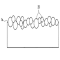
도 1은 본 발명의 주출 부재의 대표예인 플라스틱 병의 전체를 나타내는 도.
도 2는 도 1의 병 A부 단면이며, 무기 미립자를 밀어 넣어 형성한 소수성층의 상태를 나타내는 도.
도 3은 무기 미립자를 밀어 넣지 않고 형성한 소수성층의 상태를 나타내는 도.
도 4는 소수성층을 형성하는 공정을 설명하기 위한 도.
도 5는 실시예 1에서 제작한 병의 계면 프로파일을 나타내는 도.
도 6은 비교예 1에서 제작한 병의 계면 프로파일을 나타내는 도.
도 7은 참고예에서 제작한 병의 계면 프로파일을 나타내는 도.BRIEF DESCRIPTION OF THE DRAWINGS Fig. 1 is a view showing the entirety of a plastic bottle, which is a representative example of a spout member of the present invention; Fig.
Fig. 2 is a cross-sectional view of the bottle A of Fig. 1, showing the state of a hydrophobic layer formed by pushing inorganic fine particles. Fig.
3 is a view showing the state of the hydrophobic layer formed without pushing the inorganic fine particles.
4 is a view for explaining a step of forming a hydrophobic layer;
5 is a view showing the interface profile of the bottle produced in Example 1. Fig.
6 is a view showing the interface profile of the bottle produced in Comparative Example 1. Fig.
Fig. 7 is a view showing an interface profile of a bottle made in Reference Example; Fig.
본 발명의 주출 부재의 대표예인 플라스틱 병을 나타내는 도 1에 있어서, 이 병은 전체로서 (1)로 나타내는 통형상의 네크부를 상부에 갖고 있고, 이 네크부의 아래쪽에는 바깥쪽으로 만곡하여 숄더부(3)가 이어져 있으며, 숄더부(3)는 몸체부(5)로 이어지고, 몸체부(5)의 하단은 바닥부(7)로 닫혀져 있다.1 showing a plastic bottle which is a representative example of the extruding member of the present invention, the bottle has a cylindrical neck portion as shown in Fig. 1 as a whole and has a neck portion curved outwardly below the neck portion to form a shoulder portion 3 The shoulder portion 3 is connected to the body portion 5 and the lower end of the body portion 5 is closed by the bottom portion 7.
도 1로부터 이해되는 바와 같이, 네크부(1)의 외주면에는 캡을 나사 체결하기 위한 나사산(10)이 형성되어 있고, 나사산(10)의 아래쪽에는 둘레형상 돌기(11)가 형성되어 있다. 예를 들면 도시는 되어 있지 않지만, 나사 체결되어 있는 캡의 하단에 설치되어 있는 TE밴드와 해당 둘레형상 돌기(11)와의 걸어맞춤에 의해 탬퍼에비던트성이 발휘되고, 캡을 개봉했을 때 TE밴드가 용기측에 남아 TE밴드가 캡에서 제거되어 있음으로써 일반 수요자가 캡의 개봉 이력을 확인할 수 있도록 되어 있다.1, a
또 네크부(1)의 가장 아래쪽에는 큰 지름의 서포트 링(13)이 설치되어 있고, 이 서포트 링(13)을 이용하여 주출 부재인 병의 지지, 반송을 실시할 수 있도록 되어 있다. A
상기와 같은 통형상의 네크부(1)는 내용액을 따르기 위한 개구부를 구비한 주출부로 되어 있고, 본 발명에 있어서는 이 네크부(1)의 상단면(천면부)(1a)에, 도 2에 나타내어져 있는 바와 같이, 소수성을 갖는 무기 미립자(20)에 의한 소수성층이 선택적으로 형성되어 있다. 즉, 내용액과 접촉하는 내면측에는 소수성층은 형성되어 있지 않아 무기 미립자(20)는 존재하지 않는다. 따라서 반복해서 캡의 개전이 실시된 경우라도 이러한 소수성층이 용기 내에 수용되어 있는 내용액 속에 탈락하는 문제를 유효하게 방지할 수 있다.In the present invention, the tubular neck portion 1 as described above is formed as an extruding portion having an opening for following the contents liquid. In the present invention, A hydrophobic layer formed of the inorganic
또, 본 발명에 있어서는 도 2에 나타내어져 있는 바와 같이 무기 미립자(20)를 네크부(1)의 상단면(1a)에 밀어 넣도록 하여 소수성층을 형성하는 것이 바람직하다. 이에 의해, 캡의 개전이 반복해서 많이 실시되었다 해도 소수성층을 형성하는 무기 미립자(20)의 탈락이 한층 더 효과적으로 억제되어 소수성층이 안정되게 유지되므로 주출구(1a)로부터의 액체 흘러내림을 장기간에 걸쳐 방지할 수 있다. In the present invention, it is preferable that the hydrophobic layer is formed by pushing the inorganic
예를 들면 도 3에 나타내어져 있는 바와 같이 무기 미립자(20)가 상단면(1a)에 밀어 넣어져 있지 않은 경우에는 캡의 개전에 의해 무기 미립자(20)의 탈락이 일어나기 쉽게 되고, 용기 내용액 측에 무기 미립자(20)가 탈락하지 않더라도, 용기를 기울여 내용액의 따르기를 실시했을 때의 액체 흘러내림 방지 효과를 지속적으로 발휘할 수 없게 되어 버린다. For example, as shown in Fig. 3, when the inorganic
액체 흘러내림 방지용 소수성층을 형성하는 무기 미립자(20)로는 표면 처리에 의해 소수성이 부여된 것이어도 좋다. 예를 들면, 친수성 산화물 미립자를 실란 커플링제 등으로 표면 처리를 실시하여, 표면 상태를 소수성으로 한 미립자를 이용할 수도 있다. The inorganic fine particles (20) forming the hydrophobic layer for preventing liquid leakage may be those having hydrophobicity imparted by the surface treatment. For example, it is also possible to use fine particles in which the hydrophilic oxide fine particles are surface-treated with a silane coupling agent or the like to make the surface state hydrophobic.
이러한 무기 미립자(20)의 대부분은 산화물이며, 예를 들면, 실리카(이산화 규소), 알루미나, 티타니아 등의 적어도 1종을 예시할 수 있다. 또 이러한 무기 미립자(20)는 치밀한 소수성층을 형성한다는 관점에서 그 1차 입자 지름이 3~ 200nm, 특히 3~100nm의 범위에 있는 것이 좋다. 본 발명에 있어서 가장 알맞게 사용되는 것은 실란 커플링제로 표면 처리된 미세 실리카(예를 들면, 흄드 실리카)이다. Most of the inorganic
또한, 상기의 1차 입자 지름이란 투과형 전자 현미경으로 측정한 1차 입자의 평균 지름이다. The primary particle diameter is an average diameter of primary particles measured by a transmission electron microscope.
또 무기 미립자(20)에 의한 소수성층은 주출구(네크부(1)의 상단면)(1a)의 둘레 가장자리의 곡률부까지 연장되어 있어도 좋다.The hydrophobic layer formed by the inorganic
상기와 같은 네크부(1)를 구비한 병(즉, 주출구를 형성하는 기재)을 형성하기 위한 플라스틱으로는, 종래부터 용기, 특히 액체를 수용하는 용기에 사용되고 있는 것, 예를 들면, 폴리에틸렌 테레프탈레이트(PET)로 대표되는 폴리에스테르나, 폴리에틸렌, 폴리프로필렌 등의 폴리올레핀 등을 그대로 사용할 수 있고, 에틸렌 비닐 알코올 수지 등의 가스 배리어성 수지나 산소 흡수제(산화성 수지나 전이 금속 촉매)를 병용한 다층 구조를 채용하는 것도 가능하다.As the plastic for forming the bottle having the neck portion 1 (that is, the base material forming the main outlet) as described above, there has been conventionally used a container, particularly one used for a container for containing liquid, for example, Polyesters such as polyethylene terephthalate (PET), and polyolefins such as polyethylene and polypropylene can be used as they are, and gas barrier resins such as ethylene vinyl alcohol resin and oxygen absorbing agents (oxidative resin or transition metal catalyst) It is also possible to employ a multilayer structure.
본 발명에 있어서 마우스부(1)가 PET 등의 폴리에스테르에 의해 형성되어 있는 것이 가장 알맞다.In the present invention, it is most preferable that the mouth part (1) is formed of polyester such as PET.
또, 도 1은 본 발명을 플라스틱제 병에 적용한 예이지만, 이에 한정되는 것은 아니다. 1 is an example in which the present invention is applied to a plastic bottle, but the present invention is not limited thereto.
주출구를 구비한 주출 부재는 병 등의 용기에 한정되지 않고, 충전 노즐이나 자루 형상 용기 또는 종이 용기, 혹은 점적용 백 등에 부착되는 스파우트여도 되고, 스프레이 노즐, 잉크젯 노즐, 도포구여도 된다. 즉, 플라스틱제, 유리제 혹은 금속제 노즐의 적어도 주출구가 되는 부분에 수지층을 형성하고, 해당 수지층의 주출구가 되는 부분에 선택적으로 무기 미립자(20)에 의해 소수성층을 형성하면 된다. The extrusion member provided with the main outlet is not limited to a container such as a bottle, and may be a spout attached to a charging nozzle, a bag-like container or a paper container, a point application bag, or the like, or may be a spray nozzle, an inkjet nozzle or a coating applicator. That is, a resin layer may be formed at least at the main outlet of the plastic, glass, or metal nozzle, and the hydrophobic layer may be selectively formed by the inorganic
또, 상기와 같은 플라스틱제 병에 한정되지 않고 유리제, 종이제 혹은 금속제 용기여도 본 발명에 따라 주출구에 소수성층을 형성할 수 있다. 유리제, 종이제 혹은 금속제의 주출구에 플라스틱제 주출 부품을 끼워 넣음 등에 의해 고정하고, 이러한 주출 부품을 통해 내용액의 따르기가 실시되는 것이어도, 이러한 주출 부품의 상단이 되는 주출구에 무기 미립자(20)에 의해 소수성층을 형성해도 된다. In addition, the present invention is not limited to the above-mentioned plastic bottles, and the hydrophobic layer may be formed at the main outlet according to the present invention. The liquid injection part is fixed to the main outlet of the glass, paper or metal by fitting or the like, and even if the liquid content is poured through the spouting part, the inorganic fine particles ( 20 to form a hydrophobic layer.
또한, 용기의 형태도 병 형상에 한정되지 않고, 주둥이가 넓은 병 형상이나 자루 형상이어도 된다.Further, the shape of the container is not limited to the shape of the bottle, and the shape of the container may be a wide bottle shape or a bag shape.
상술한 소수성층을 구비한 주출 부재는, 용기를 예로 들면 대표적으로는 다음과 같이 하여 제조된다. The extrusion member having the above-mentioned hydrophobic layer is typically manufactured in the following manner, for example, as a container.
우선 도 4에 나타내어진 것과 같은 프리폼(50)을 성형한다. 프리폼은 종래 공지의 압축 성형 또는 사출 성형에 의해 성형할 수 있다. First, the
압축 성형에 의한 프리폼 성형에 있어서는 압출기에 의해 전술한 용기용 플라스틱 용융물을 연속적으로 밀어내는 동시에, 합성수지 공급 장치의 절단 수단(커터)에 의해 이것을 절단하며, 용융 상태에 있는 프리폼용 전구체인 용융 수지 덩어리(드롭)을 제조하고, 이 용융 수지 덩어리를 홀딩 수단(홀더)으로 홀딩하며, 압축 성형기의 캐비티 몰드에 안내 수단(스로트)을 통해 투입한 뒤 이것을 코어 몰드로 압축 성형하고 냉각 고화함으로써 프리폼을 성형한다. In the preform molding by compression molding, the above-mentioned plastic melted material for a container is continuously pushed out by an extruder, and this is cut by a cutting means (cutter) of a synthetic resin feeding device, and a melted resin lump (Droplet) is held. The molten resin mass is held by a holding means (holder). The molten resin mass is put into a cavity mold of a compression molding machine through guiding means (throat), compression molded by a core mold, .
또 사출 성형에 의한 프리폼 성형에 있어서는 사출 조건은 특별히 한정된 것은 아니지만, 일반적으로 260~300℃의 사출 온도, 30~60kg/㎠의 사출 압력으로 바닥이 있는 프리폼을 성형할 수 있다.In the preform molding by injection molding, the injection conditions are not particularly limited, but generally, a preform having a bottom can be molded at an injection temperature of 260 to 300 캜 and an injection pressure of 30 to 60 kg / cm 2.
상기와 같이 하여 형성되는 프리폼(50)에는 전술한 도 1에 나타내어져 있는 형상의 네크부(1)가 형성되어 있다. In the
이 프리폼(50)에 발수성을 부여하기 위한 소수성층을 전술한 무기 미립자(20)를 이용하여 형성한다. A hydrophobic layer for imparting water repellency to the
우선 도 4에 나타내어져 있는 바와 같이, 소수성층 형성용 지그(60)를 준비한다. First, as shown in Fig. 4, a
이 지그(60)는 강성의 금속 등으로 형성되어 있고, 프리폼(50)의 마우스부(1)의 상단 부분을 삽입할 수 있는 크기의 오목부(63)가 형성되어 있다. 이 지그(60)의 오목부(63) 내에 전술한 무기 미립자(20)의 분말을 충전하거나 혹은 빈틈없이 깐다. 이 상태로 오목부(63) 내의 무기 미립자(20)를 가열한다.The
본 발명에 있어서는 이와 같이 무기 미립자(20)가 가열된 상태에서 도립 상태의 프리폼(50)을 하강시켜, 그 네크부(1)를 오목부(63) 내에 삽입하고 일정 압력으로 누른다. 이러한 누름은 에어 실린더나 캠 장치 등의 공지의 장치를 이용하여 용이하게 실시할 수 있다.In the present invention, the
이와 같이 하여 무기 미립자(20)를 상단면(1a)에 선택적으로 밀어 넣고, 상단면(1a)에 소수성층을 선택적으로 형성할 수 있다. In this manner, the inorganic
예를 들면, 무기 미립자(20)가 분산된 도포액을 준비하고 그것을 딥핑 또는 스프레이 분무, 솔 칠 등에 의해 도포하고 건조함으로써 소수성층을 상단면(1a)에 형성할 수도 있지만, 이와 같은 수단으로는 도포액의 흘러내림 등에 의해 상단면(1a) 이외의 부분에도 소수성층이 형성되기 쉬워져 버린다. 상단면(1a) 이외의 부분에도 소수성층을 형성한 경우, 상술한 바와 같이 반복해서 캡의 개전이 실시된 경우 이러한 소수성층이 용기 내에 수용되어 있는 내용액 속에 탈락하고, 발수성이 소실되어 버릴 우려가 있다. For example, a hydrophobic layer may be formed on the
또 도시하지 않지만, 무기 미립자의 분말을 직접 지그에 충전하지 않고 소수성층을 형성할 수도 있다. 예를 들면, 무기 미립자를 포함하는 도료를 2축 연신 PET필름 등에 도포, 건조시킴으로써 필름 상에 소수성층을 형성시킨다. 다음으로 이 필름을 상면이 평탄한 지그 상에 배치하고, 지그와 필름을 가열시켜 프리폼을 일정한 압력으로 누른다. 이러한 방법으로도 발수성을 부여한 소수성층을 형성하는 것이 가능하다. 무기 미립자의 층을 형성시킬 때의 필름 형상 혹은 롤 형상 물질의 재질로는 상술한 2축 연신 PET, 2축 연신 폴리프로필렌 등의 플라스틱, 알루미늄이나 스틸 등의 금속 등을 이용할 수 있다. 선택하는 재질로는 가공 온도에 있어서의 소수성층을 형성하는 기재(목적물)의 경도와 필름 형상 물질의 경도를 고려하여 적절히 선택하면 된다. Although not shown, the hydrophobic layer may be formed without directly charging the inorganic fine particle powder into the jig. For example, a paint containing inorganic fine particles is applied to a biaxially oriented PET film or the like and dried to form a hydrophobic layer on the film. Next, the film is placed on a flat jig whose top surface is flat, and the jig and the film are heated to press the preform at a constant pressure. With this method, it is also possible to form a hydrophobic layer imparting water repellency. As the material of the film or roll material for forming the inorganic fine particle layer, it is possible to use the above-mentioned biaxially oriented PET, plastic such as biaxially oriented polypropylene, metal such as aluminum or steel, and the like. The material to be selected may be appropriately selected in consideration of the hardness of the substrate (object) forming the hydrophobic layer at the processing temperature and the hardness of the film-like material.
또한, 상기와 같은 가열은 예를 들면 지그(60)에 히터 등을 내장시켜 두어도 되고, 고주파 가열 또는 초음파 진동 등의 수단에 의해 외부로부터 선택적으로 오목부(63) 내의 무기 미립자(20)를 가열할 수도 있다. For example, the
또 가열 온도는 밀어 넣어진 프리폼(50)의 네크부(1)의 상단면(1a) 내에 무기 미립자(20)가 밀어 넣어지는 정도의 온도이며, 네크부(1)를 형성하는 플라스틱의 종류나 물성에 따라 적절한 온도로 하면 된다. 예를 들면, 비정질의 PET에 의해 네크부(1)가 형성되어 있는 경우에는 40~140℃ 정도이다.The heating temperature is a temperature at which the inorganic
본 발명에 있어서는 상술한 바와 같이 하여 형성된 소수성층을 갖는 프리폼(50)을 연신 블로우 성형하고, 도 1에 나타내어져 있는 병 형상의 용기로 한다. In the present invention, the
연신 블로우 성형에 앞서, 필요에 따라 프리폼(50)을 열풍, 적외선 히터, 고주파 유도 가열 등의 수단으로 연신 적성 온도까지 예비 가열한다. 특별히 높은 내열성과 기계적 강도를 연신 용기에 부여함에 있어서는 그 온도 범위는 PET수지의 경우 85~130℃, 특히 100~120℃의 범위에 있는 것이 좋다.Prior to the stretch blow molding, the
상기와 같이 하여 무기 미립자(20)를 프리폼(50)의 마우스부(1)의 상단 부분에 압착한 뒤 에어 블로우 등에 의해 마우스부(1)의 상단면(1a) 이외의 부분에 부착되어 있는 무기 미립자(20)를 제거하고, 이에 따라 상단면(1a)에 선택적으로 무기 미립자(20)의 소수성층을 형성할 수 있다.The
이 프리폼(50)을 그 자체 공지의 연신 블로우 성형기 중에 공급하고 금형 내에 세트하여, 연신봉(延伸棒)의 밀어넣기에 의해 축 방향으로 인장 연신하는 동시에 유체의 취입(blowing)에 의해 둘레 방향으로 연신 성형한다. 금형 온도는 일반적으로 실온 내지 230℃의 범위에 있는 것이 바람직하지만, 후술하는 바와 같이 원 몰드(one-molding)법으로 열 고정을 실시하는 경우는 금형 온도를 120~180℃로 설정하는 것이 바람직하다.The
최종 PET수지 용기의 연신 배율은 면적 배율로 1.5~25배가 적당하며, 이 중에서도 축 방향 연신 배율을 1.2~6배로 하고, 둘레 방향 연신 배율을 1.2~4.5배로 하는 것이 바람직하다.The stretching magnification of the final PET resin container is suitably 1.5 to 25 times as large as the area magnification, and it is preferable that the axial stretching magnification is 1.2 to 6 times and the circumferential stretching magnification is 1.2 to 4.5 times.
또, 블로우 성형 금형과는 별개의 열 고정용의 금형 내에서 실시하는 투 몰드(two-molding)법으로 실시할 수도 있다.It may also be carried out by a two-molding method which is carried out in a mold for heat fixation, which is separate from the blow-molding mold.
또한, 전술한 제조 방법에 있어서는 프리폼(50)에 소수성층을 형성했지만, 프리폼(50)으로 형성된 용기에 마찬가지로 하여 소수성층을 형성하는 것도 가능하다.Further, in the above-described manufacturing method, the hydrophobic layer is formed in the
또, 유리제 또는 금속제 용기에 플라스틱제 주출부가 끼워넣어진 형태의 용기에 대해서는 이와 같은 주출부가 끼워넣어진 상태로 상기와 마찬가지로 하여 소수성층을 형성할 수 있다.In addition, in the case of a container in which a plastic extruded part is embedded in a glass or metal container, the hydrophobic layer can be formed in the same manner as above with the extruded part sandwiched therebetween.
본 발명이 뛰어난 효과를 가지는 것은 이하의 사실로부터 추찰된다. 무기 미립자(20)를 밀어 넣음으로써 수지층과 소수성층의 밀착성이 향상되고, 또 소수층의 구조가 견고하게 되어 있다. 이것은 후술하는 실시예에 기재한 소수성층과 기재 측과의 계면 프로파일 측정으로부터도 이해할 수 있는 바와 같이 무기 미립자 자체가 기재의 수지층에 밀어 넣어짐으로써 수지층과 소수성층과의 계면이 불명료하게 됨에 따라 밀착성이 향상되고, 그 결과로서 소수성층의 구조가 견고해 진 것으로 생각된다. 예를 들면, 무기 입자(20)를 밀어 넣음으로써 형성되는 소수성층에 있어서는 기재 측과의 계면 프로파일은 0.05㎛ 이상의 표면 거칠기 Rz(JIS B-0601-2001)를 갖고 있다.It is presumed from the following facts that the present invention has an excellent effect. The adhesion of the resin layer and the hydrophobic layer is improved by pushing the inorganic
한편, 도포액을 이용한 딥핑에 의해 수지층 상에 소수성층을 형성한 경우, 수지층과 소수성층과의 계면은 명료하게 나뉘어 있어, 밀착성이 매우 낮기 때문에 소수성층을 형성하는 무기 미립자는 박리, 탈락하기 쉬운 것으로 생각된다. 그 계면 프로파일의 표면 거칠기는 0.05㎛보다 작다.On the other hand, when the hydrophobic layer is formed on the resin layer by dipping using the coating liquid, since the interface between the resin layer and the hydrophobic layer is clearly divided and the adhesion is very low, the inorganic fine particles forming the hydrophobic layer are peeled off Is thought to be easy. The surface roughness of the interface profile is smaller than 0.05 탆.
본 발명에 있어서, 상기와 같은 견고한 구조를 광범위에 걸쳐 형성하려면, 무기 미립자를 부착시킨 필름을 준비하고, 기재 측에 롤로 압착하며, 무기 미립자를 기재 측에 옮김으로써 기재의 표면에 소수성층을 광범위에 걸쳐 형성할 수 있다. 하기는 자루 형상 용기의 내면에 소수성층을 형성한 층 구성의 예이다.In order to form a solid structure as described above over a wide range in the present invention, a film to which inorganic fine particles are adhered is prepared, and the inorganic fine particles are transferred to the substrate side with a roll on the substrate side. As shown in Fig. The following is an example of a layer configuration in which a hydrophobic layer is formed on the inner surface of the bag-shaped container.
올레핀층/알루미늄층/올레핀층/소수성층Olefin layer / aluminum layer / olefin layer / hydrophobic layer
올레핀층/EVOH층/올레핀층/소수성층Olefin layer / EVOH layer / olefin layer / hydrophobic layer
본 발명은 내용액을 따를 때의 액체 흘러내림을 유효하게 방지할 수 있으므로 액체 흘러내림 방지의 이점이 가장 발휘될 수 있도록 용기의 형태 및 내용액을 선택하는 것이 바람직하다. Since the present invention can effectively prevent the liquid flowing down when the liquid is followed, it is preferable to select the form and the liquid content of the container so that the advantage of the prevention of the liquid flow-down can be most exerted.
예를 들면, 내용액으로는 고점성의 것에서부터 저점성의 것까지 특별히 제한되지 않고 사용할 수 있지만, 예를 들면 비탄산 음료용 용기로서 본 발명의 용기는 특히 알맞다. 즉, 탄산 음료는 탄산이 용해되어 있기 때문에 어느 정도의 용적의 헤드 스페이스가 확보되도록 충전되지만, 비탄산 음료는 헤드 스페이스를 남기지 않고 거의 꽉 찬 상태로 충전된다. 이 때문에 처음에 따르기를 실시할 때에는 용기를 살짝 기울인 상태(용기가 직립에 가까운 상태)로 액체의 주출이 개시되므로 액체 흘러내림이 매우 발생하기 쉽다. 본 발명에서는 이와 같은 비탄산 음료의 초기 주출 시에 있어서도 효과적으로 액체 흘러내림을 방지할 수 있다.For example, the content liquid can be used without particular limitation from a high viscosity to a low viscosity. For example, the container of the present invention is particularly suitable as a non-carbonated beverage container. That is, the carbonated beverage is charged so that the head space of a certain volume is ensured because carbonic acid is dissolved, but the non-carbonated beverage is filled in a substantially full state without leaving a head space. For this reason, when pouring is carried out for the first time, the pouring of liquid is likely to occur very slowly since the pouring of the liquid is started in a state in which the container is slightly tilted (the container is close to the upright position). In the present invention, it is also possible to effectively prevent the liquid from flowing down even during the initial feeding of the non-carbonated beverage.
또 플라스틱제 용기에 있어서는 내열성을 부여하기 위한 열 결정화에 의해 용기 마우스부가 흰색으로 형성되어 있는 동시에, 내용액이 유색 액체, 예를 들면 커피, 간장, 각종 주스류 등의 경우에는 액체 흘러내림이 생겼을 때 내용액에 의한 용기 마우스부의 더러움이 매우 두드러지게 된다. 때문에 이러한 경우에 있어서 액체 흘러내림 방지가 효과적으로 실시되는 본 발명은 매우 유용하다.Further, in the case of the plastic container, the mouth portion of the container is formed white by thermal crystallization for imparting heat resistance, and when the liquid is a colored liquid such as coffee, soy sauce, various kinds of juice, etc., The dirt of the mouth portion of the container due to the contents liquid becomes very conspicuous. Therefore, the present invention in which liquid leakage prevention is effectively performed in such a case is very useful.
또한, 음료에 있어서는 500㎖ 이상의 용적의 병에 본 발명을 적용하는 것이 바람직하다. 즉, 180㎖ 정도의 작은 용적의 음료병에서는 수요자는 용기 마우스부에서 직접 마시는 경우가 많지만, 용적이 커질수록 내용액의 음료를 컵 등에 옮겨서 마시기 때문에 액체 흘러내림의 문제가 생긴다. 따라서 이와 같은 용적이 큰 음료병에 본 발명을 적용하는 것도 효과적이다. Further, it is preferable to apply the present invention to bottles having a volume of 500 ml or more in beverages. That is, in a beverage bottle of a small volume of about 180 ml, a consumer usually drinks directly from the mouth portion of the container. However, as the volume increases, the beverage of the content liquid is transferred to the cup or the like and the liquid flows down. Therefore, it is also effective to apply the present invention to a beverage bottle having such a large volume.
이상 본 발명의 주출 부재를 병 등의 용기 또는 용기용 프리폼을 예로 들어 설명했으나, 이미 언급한 바와 같이 본 발명의 주출 부재는 점성 유체(즉, 음료 등의 식품류 등으로 대표되는 액체)를 배출하는 주출구를 구비하고 있는 것이면 특별히 제한 없이 적용할 수 있고, 예를 들어 주출구 부착의 캡, 자루 형상 용기 또는 종이 용기 등에 부착되는 스파우트, 기타 충전 노즐 또는 잉크젯 노즐 등의 노즐에도 본 발명을 적용할 수 있다.
As described above, the extruding member of the present invention is an extruding member of the present invention, which has been described above by taking the preform for a container or a container such as a bottle as an example, The present invention can be applied to a nozzle such as a spout attached to a cap, a bag-like container or a paper container with a main outlet, or other filling nozzle or ink-jet nozzle. .
실시예Example
본 발명의 뛰어난 효과를 다음의 실험에 의해 설명한다.The excellent effects of the present invention will be explained by the following experiments.
A. PET병에 대한 시험A. Testing for PET bottles
(피막의 밀착성 시험) (Coating adhesion test)
하기 실시예 및 비교예의 방법으로 발수성을 향상시킨 샘플병으로서 용적 500㎖의 PET병을 사용하고, 각각의 병에 대해 내용액으로 85℃의 커피(25℃에서의 점도: 10mPa·s(B형 점도계))를 480㎖ 충전했다. 충전 후, 폴리프로필렌제 캡으로 밀봉한 뒤 흐르는 물로 냉각했다.A PET bottle having a volume of 500 ml was used as a sample bottle improved in water repellency by the methods of the following examples and comparative examples, and each of the bottles was filled with 85 캜 of coffee (viscosity at 25 캜: 10 mPa ( Viscometer)) was charged to 480 ml. After filling, it was sealed with a cap made of polypropylene and cooled with flowing water.
냉각 후, 장착한 캡을 개전하여 내용액 측에 부유물이 있는지 여부를 눈으로 확인했다. 부유물이 확인되지 않은 것을 ○, 부유물이 확인된 것을 ×로 했다.After cooling, the mounted cap was opened to visually confirm whether there was any floating matter on the content liquid side. ○ that the float was not confirmed, and × that the float was confirmed.
(액체 흘러내림성 시험) (Liquid spillability test)
상술한 피막의 밀착성 시험을 실시한 후, 각각의 샘플에 대해 소정의 지그를 이용하여, 미리 사람이 병을 잡고 손으로 따르는 동작을 바탕으로 중심과 기울임 각도를 데이터화한 데이터에 의거하여 이동, 회전을 실시하고, 액체 흘러내림 상태를 눈으로 관찰했다. 나사산이 형성되어 있는 부분에까지 내용액이 흘러 떨어진 것을 ×, 나사산이 형성되어 있는 부분에까지 내용액이 흘러 떨어지지 않고 액체 차단된 것을 ○로 평가했다.After the above-mentioned adhesion test of the film was carried out, movement and rotation were performed on each sample based on data obtained by digitizing the center and the tilt angle based on the operation of manually holding the bottle and manually pouring the sample in advance using a predetermined jig And the state of liquid flowing down was visually observed. The results of the evaluation were as follows: the content liquid flowed down to the part where the thread was formed, and the case where the liquid was not dropped to the part where the thread was formed,
(발수 지속성 시험)(Water repellency test)
하기의 실시예 및 비교예의 방법으로 발수성을 향상시킨 각각의 샘플병에 내용액으로 85℃의 커피(25℃에서의 점도: 10mPa·s(B형 점도계)를 480㎖ 충전했다. 충전 후, 폴리프로필렌제 캡으로 밀봉한 뒤 흐르는 물로 냉각했다. 냉각 후, 22℃ 60%RH의 환경하에서 소정 일수 보관했다. 보관 후, 캡을 개전하여 액체 흘러내림성 시험을 실시했다. 시험 후, 노즐의 발수성 피막부의 내용액의 부착 유무를 눈으로 확인했다. 발수성 피막부에 내용액의 부착이 보이지 않은 것을 ○, 부착이 보인 것을 ×로 평가했다.Each of the sample bottles improved in water repellency by the methods of the following Examples and Comparative Examples was filled with 480 ml of coffee (viscosity at 25 캜: 10 mPa · (B-type viscometer) at 85 캜 as an inner liquid. The cap was opened and the liquid flowability test was carried out. After the test, the water repellency of the nozzle was measured, and the water repellency of the nozzle was measured. And the presence or absence of the content solution in the film portion was visually confirmed. The film having no adhesion of the content solution to the water repellent film portion was evaluated as & cir &
(계면 프로파일 측정)(Interfacial Profile Measurement)
제작한 주출구를 에탄올에 담그고, 초음파 진동을 가하여 소수성층을 형성하는 실리카 미립자를 제거했다. 소수성층을 제거한 부분의 기재 측의 표면 거칠기를 표면 거칠기·형상 통합 측정기(SURFCOM2000SD3-13,(주)도쿄세이미츠 제조)로 측정하고, 이 프로파일을 소수성층과 기재 측과의 계면 프로파일로 했다. 하기 조건으로 측정을 실시했다. The produced main outlet was immersed in ethanol, and ultrasonic vibration was applied to remove the fine silica particles forming the hydrophobic layer. The surface roughness of the substrate side where the hydrophobic layer was removed was measured with a surface roughness and shape integrating meter (SURFCOM2000SD3-13, manufactured by Tokyo Seimitsu Co., Ltd.), and this profile was used as the interface profile between the hydrophobic layer and the substrate side. Measurement was carried out under the following conditions.
측정 길이 : 0.7㎜Measuring length: 0.7 mm
측정 속도 : 0.300㎜/sMeasurement speed: 0.300 mm / s
예비 구동 길이 : λc/3×2 Preliminary drive length: lambda c / 3 x 2
측정 범위 : ±6.400㎛ Measuring range: ± 6.400㎛
산출 규격 : JIS-'01 규격Specification: JIS-01 standard
λs컷오프비 : 300λs cut-off ratio: 300
컷오프 종별 : 가우시안Cutoff type: Gaussian
컷오프 파장(λc) : 0.025㎜Cut-off wavelength (? C): 0.025 mm
평가 길이 : 0.500㎜Evaluation length: 0.500 mm
또한, 거칠기 곡선으로부터, 산술 평균 거칠기 Ra, 최대 높이 거칠기 Rz는 JIS-'01의 산출 규격에 의거하여 기준 길이 0.025㎜, 평가 길이 0.500㎜에서의 평균값(n=20)으로서 산출했다. From the roughness curve, the arithmetic mean roughness Ra and the maximum height roughness Rz were calculated as an average value (n = 20) at a reference length of 0.025 mm and an evaluation length of 0.500 mm based on the calculation standard of JIS-01.
B. 풀 링 부착 힌지 캡에 대한 시험B. Test on hinged cap with pull ring
(피막의 밀착성 시험)(Coating adhesion test)
하기 실시예의 방법으로 발수성을 향상시킨 풀 링(pull-ring) 부착 힌지 캡, 내용량 500㎖ 상당의 폴리에틸렌 테레프탈레이트(PET)제의 병을 준비하고, 병에 내용액으로 25℃로 간장을 500㎖ 충전했다. 충전 후, 발수성을 향상시킨 힌지 캡으로 밀봉했다. A bottle made of polyethylene terephthalate (PET) having an inner volume of 500 ml and a pull ring with a water repellency improved by the method of the following example was prepared, and 500 ml of soy sauce Charged. After filling, the container was sealed with a hinge cap having improved water repellency.
그 후, 장착한 힌지 캡의 풀 링을 뽑아 개봉한 뒤 일단 뚜껑을 닫고 내용액 측에 부유물이 있는지 여부를 눈으로 확인했다. 부유물이 확인되지 않은 것을 ○, 부유물이 확인된 것을 ×로 했다.Thereafter, the pull ring of the hinge cap was pulled out and opened, and then the lid was closed and visually confirmed whether or not there was floating matter on the contents liquid side. ○ that the float was not confirmed, and × that the float was confirmed.
(액체 흘러내림성 시험) (Liquid spillability test)
상술한 피막의 밀착성 시험으로 액체 흘러내림 상태를 눈으로 관찰했다. 주출부에서 액체가 차단되지 않고 주출부로부터 내용액(간장)이 흘러 떨어진 것을 ×, 내용액이 주출부에서 액체 차단된 것을 ○로 평가했다.The liquid flow-down state was visually observed by the above adhesion test of the film. (X) in which the liquid was not blocked in the extruding part and the content liquid (soy sauce) was discharged from the extruding part, and that in which the content liquid was blocked by the extruding part was evaluated as?.
(발수 지속성 시험) (Water repellency test)
하기 실시예의 방법으로 발수성을 향상시킨 풀 링 부착 힌지 캡, 내용량 500㎖ 상당의 폴리에틸렌 테레프탈레이트(PET)제의 병을 준비하고, 병에 내용액으로 25℃로 간장을 500㎖ 충전했다. 충전 후, 발수성을 향상시킨 힌지 캡으로 밀봉했다. A bottle made of polyethylene terephthalate (PET) having an inner volume of 500 ml and a pull ring with an improved water repellency by the method of the following example was prepared, and the bottle was filled with 500 ml of soy sauce at 25 캜 as a content liquid. After filling, the container was sealed with a hinge cap having improved water repellency.
그 후, 장착한 힌지 캡의 풀 링을 뽑아 개봉한 후, 내용액 약 20㎖를 따르고 힌지 캡을 닫았다. 그 후 다시 힌지 캡을 열어 내용액을 약 20㎖ 따르고 힌지 캡을 닫았다. 이 동작을 소정 횟수 개폐한 시점에서의 발수성 피막부의 내용액의 부착 유무를 눈으로 확인하고, 병의 발수 지속성 시험과 마찬가지로 하여 평가했다. Thereafter, the pull ring of the mounted hinge cap was pulled out and opened, and the hinge cap was closed by pouring about 20 ml of the content liquid. Then, the hinge cap was opened again to pour about 20 ml of the content liquid, and the hinge cap was closed. The presence or absence of the attachment of the liquid content of the water-repellent film portion at the time when this operation was performed a predetermined number of times was visually confirmed and evaluated in the same manner as the bottle water repellency persistence test.
이하의 실시예 1, 2, 비교예 1 및 참고예는 PET병에 본 발명을 적용했을 때의 실험예이다.The following Examples 1 and 2, Comparative Example 1 and Reference Example are experimental examples when the present invention is applied to a PET bottle.
<실시예 1>≪ Example 1 >
사출 성형기(NN75JS, 니이가타텟코쇼 제조)를 사용하고, 건조 처리된 폴리에틸렌 테레프탈레이트(PET) 수지(RT543CTHP, 니혼유니페트(주))를 배럴 설정 온도 280℃, 사이클 타임 30초로 사출 성형하고, 중량 28g(500㎖ PET병용)의 비결정 프리폼을 성형했다. (PET) resin (RT543CTHP, manufactured by Nippon Unipet) using an injection molding machine (NN75JS, manufactured by Niigata Tetsudo Co., Ltd.) and injection molding at a barrel set temperature of 280 DEG C and a cycle time of 30 seconds, 28 g (500 ml PET combination) of amorphous preform was molded.
성형 후, 하형(下型)(소수성층 형성용 지그(60))으로 밴드 히터를 장착하고, 상면에 지름 32㎜, 깊이 1.8㎜의 움푹 팬 곳(오목부(63))이 있는 알루미늄제의 몰드를 마련하여, 이 움푹 팬 곳에 소수성 실리카(RX300, 니혼아에로질 제조)를 충전했다.After the molding, a band heater was attached to the lower mold (
충전 후, 밴드 히터로 하형 전체를 60℃로 가열했다. 상형(上型)으로 프리폼을 고정 가능한 알루미늄제의 몰드를 준비하여, 성형한 비결정 프리폼의 노즐부를 아래쪽을 향하게 고정하고, 하형에 가공면의 압력 72MPa로 3.2초간 프레스하여 비결정 프리폼의 노즐 천면(天面)에 소수성 실리카를 압착했다.After charging, the entire lower mold was heated to 60 DEG C with a band heater. A mold made of aluminum capable of fixing the preform with an upper mold was prepared, the nozzle part of the formed amorphous preform was fixed downward, and the lower mold was pressed for 3.2 seconds at the pressure of the working surface at a pressure of 72 MPa to form the nozzle surface of the amorphous preform Surface) was pressed with hydrophobic silica.
압착 후, 에어 블로잉으로 미압착된 소수성 실리카를 제거했다. 그 후, 마우스부를 가열에 의해 결정 백화시켰다. 그 후, 이 프리폼의 몸체부를, 외측으로부터 적외선 히터로, 내부에서 가열 철심에 의해, 소정의 표면 온도로 가열한 뒤, 2축 연신 블로우하여 대략적인 연신 배율이 세로 3배, 가로 3배, 면적 9배가 되는 용량 500㎖의 도 1에 나타내는 연신 블로우 병을 성형했다. 금형 온도는 90~150℃의 범위로 설정했다. 또, 에어 블로잉에는 실온(20℃)의 압축 공기를 사용하고, 이형(離型) 시에는 용기 내에 실온(20℃)의 쿨링 에어를 도입했다.After the pressing, the hydrophobic silica uncombined by air blowing was removed. Thereafter, the mouse part was crystallized by heating. Thereafter, the body portion of the preform was heated to a predetermined surface temperature by a heated iron core from the inside with an infrared heater from the outside, and then biaxially stretched blow to obtain a stretch ratio of roughly 3 times, 3 times, A stretch blow bottle as shown in Fig. 1 having a capacity of nine times as large as 500 ml was formed. The mold temperature was set in the range of 90 to 150 ° C. Compressed air at room temperature (20 ° C) was used for air blowing, and cooling air at room temperature (20 ° C) was introduced into the container at the time of releasing.
작성한 노즐부에 소수성 실리카를 압착한 500㎖의 PET병을 이용하여 상술한 피막의 밀착성 시험, 액체 흘러내림성 시험 및 발수 지속성 시험을 실시했다. 결과를 표 1에 나타낸다. 또한 주사형 전자 현미경을 이용한 관찰로 이 페트병의 노즐부 상단면(주출부 상단면(1a))에 선택적으로 소수성층이 형성되어 있는 것이 확인됐다. A 500 ml PET bottle in which hydrophobic silica was compressed to the prepared nozzle portion was subjected to the adhesion test, the liquid flowability test, and the repellency test of water repellency described above. The results are shown in Table 1. It was also confirmed by observation using a scanning electron microscope that a hydrophobic layer was selectively formed on the top surface (
또한, 작성된 병을 이용하여 소수성층과 기재 측과의 계면 프로파일 측정을 실시했다. 얻어진 결과를 표 2 및 도 5에 나타낸다.Further, the interface profile between the hydrophobic layer and the substrate side was measured using the prepared bottle. The obtained results are shown in Table 2 and Fig.
<실시예 2> ≪ Example 2 >
폴리에스테르 수지(바일론 200, 도요보 제조) 0.4g, 메틸에틸케톤(와코준야쿠 제조) 100g 및 스터러 칩을 유리병 안에 넣고 밀폐하여 수지가 용해될 때까지 스터러로 충분히 교반했다. 그 후 소수성 실리카(RX300, 니혼아에로질 제조) 3g을 더 더하여 스터러로 30분간 교반했다. 교반 후, 30분간 초음파 처리를 실시하여 균일한 용액을 얻었다. 0.4 g of a polyester resin (
두께 100㎛의 PET필름의 한쪽 면에 바코터를 이용하여 얻어진 용액을 도포하고, 100℃의 오븐에서 2분간 건조시켜 소수성 실리카 피복 필름을 얻었다. 본 필름 상에 물 방울을 떨어뜨렸더니, 작은 물방울도 부착하지 않고 필름 위를 대굴대굴 굴러 초발수성을 나타내고 있었다.A solution obtained by using a bar coater was applied to one side of a PET film having a thickness of 100 占 퐉 and dried in an oven at 100 占 폚 for 2 minutes to obtain a hydrophobic silica-coated film. Water droplets were dropped on the film, and no water droplets were adhered to the film.
하형의 상면에 경질 우레탄 고무를 구비한 알루미늄제의 블록을 준비하고, 하형의 상면에 상술한 소수성 실리카 피복 필름을 놓고, 하형 전체를 100℃로 가열, 가공면의 압력 24MPa로 한 것 이외는 실시예 1과 같은 방법으로 PET병을 얻었다. Except that a block made of aluminum having a hard urethane rubber on the upper surface of the lower mold was prepared and the above hydrophobic silica-coated film was placed on the lower surface of the lower mold and the entire lower mold was heated to 100 캜 and the pressure of the working surface was 24 MPa. PET bottles were obtained in the same manner as in Example 1.
얻어진 PET병에 대해 피막의 밀착성 시험, 액체 흘러내림성 시험 및 발수 지속성 시험을 실시했다. 결과를 표 1에 나타낸다.The resulting PET bottle was subjected to a coating adhesion test, a liquid flowability test, and a water repellency persistence test. The results are shown in Table 1.
또한 주사형 전자 현미경을 이용한 관찰로 이 페트병의 노즐부 상단면(주출부 상단면(1a))에 선택적으로 소수성층이 형성되어 있는 것이 확인됐다.It was also confirmed by observation using a scanning electron microscope that a hydrophobic layer was selectively formed on the top surface (
<비교예><Comparative Example>
소수성 실리카(RX300, 니혼아에로질 제조) 3g을 에탄올(특급, 와코준야쿠 제조) 97g 및 스터러 칩을 유리병 안에 넣고 밀폐하여 30분간 스터러로 교반한 뒤 30분간 초음파 처리를 실시했다. 이 혼합물에 테트라에톡시실란(신에쓰가가꾸 제조) 0.54g, 염산(1N) 0.04g, 순수(純水) 0.16g의 순서로 적하·혼합했다. 그 후, 이 혼합액을 2.5시간 스터러로 교반하고 30분 초음파 처리하여 발수성 코팅액으로 했다.97 g of ethanol (manufactured by Wako Pure Chemical Industries, Ltd.) and 3 g of hydrophobic silica (RX300, manufactured by Nippon Aerosil Co., Ltd.) and a stirrer chip were placed in a glass bottle and stirred with a stirrer for 30 minutes, followed by ultrasonic treatment for 30 minutes . To this mixture, 0.54 g of tetraethoxysilane (Shin-Etsu Chemical Co., Ltd.), 0.04 g of hydrochloric acid (1N) and 0.16 g of pure water were added dropwise in this order. Thereafter, this mixed solution was stirred with a stirrer for 2.5 hours and ultrasonicated for 30 minutes to obtain a water-repellent coating solution.
실시예 1과 마찬가지로 비결정 프리폼을 성형했다. 그 후 마우스부를 가열에 의해 결정 백화 프리폼을 제작한 것 외에는 실시예 1과 마찬가지로 하여 블로우 병을 성형했다. 성형한 PET병의 노즐부를 하측으로 하고, 병의 나선의 시작 위치까지 상술한 발수성 코팅 용액에 5초간 침지한 뒤 2㎜/min의 속도로 끌어올려 30분간 실온에서 건조시켜 PET병을 얻었다. An amorphous preform was formed in the same manner as in Example 1. Thereafter, a blow bottle was formed in the same manner as in Example 1, except that a crystal whitening preform was produced by heating the mouse portion. The nozzle part of the molded PET bottle was set to the lower side and immersed in the above water repellent coating solution for 5 seconds to the start position of the bottle helix, then pulled up at a rate of 2 mm / min and dried at room temperature for 30 minutes to obtain a PET bottle.
얻어진 PET병에 대해 상술한 피막의 밀착성 시험, 액체 흘러내림성 시험 및 발수 지속성 시험, 계면 프로파일 측정을 실시했다. 결과를 표 1, 표 2, 도 6에 나타낸다.The obtained PET bottle was subjected to the adhesion test, the liquid flowability test, the water repellency persistence test, and the interface profile measurement described above. The results are shown in Tables 1, 2, and 6.
<참고예><Reference example>
소수성층을 형성시키지 않은 것 이외는 실시예 1과 마찬가지로 하여 PET병을 제작했다. 얻어진 PET병에 대해 상술한 계면 프로파일 측정을 실시했다. 결과를 표 2, 도 7에 나타낸다. 또한, 본 참고예에서의 계면 프로파일은 소수성층을 형성시키고 있지 않기 때문에 PET병의 표면 프로파일을 나타내고 있다. A PET bottle was produced in the same manner as in Example 1 except that no hydrophobic layer was formed. The above-mentioned interfacial profile measurement was performed on the obtained PET bottle. The results are shown in Table 2 and Fig. In addition, the interface profile in this Reference Example shows the surface profile of the PET bottle because the hydrophobic layer is not formed.
피막의 밀착성 시험 결과로부터, 비교예 1에서는 캡 개전시에 발수성 피막이 파괴되어 내용품 측으로 이동하여 부유물이 되는 것이 확인됐다. 따라서, 실제 사용에 견딜 수 있는 밀착성이 없음을 알 수 있다. From the result of the adhesion test of the film, it was confirmed that in Comparative Example 1, the water repellent film was broken in the opening of the cap, and the water repellent film moved to the article side and became a float. Therefore, it can be seen that there is no adhesion that can withstand actual use.
한편, 실시예 1 및 실시예 2에서는 개전 후에도 부유물이 확인되지 않았다. 이것은 발수성 피막이 파괴되지 않았기 때문으로 생각된다. 이 사실로부터 발수성 피막과 기재(PET수지) 사이에 충분한 밀착성을 갖는 것을 알 수 있다.On the other hand, in Examples 1 and 2, no floating matters were observed after the opening. This is probably because the water-repellent film was not destroyed. From this fact, it can be seen that there is sufficient adhesion between the water-repellent film and the substrate (PET resin).
액체 흘러내림성 시험의 결과로부터 실시예 1, 2, 비교예 1 모두 액체 흘러내림이 없고 양호한 액체 차단성을 갖고 있는 것을 알 수 있다.From the results of the liquid flowability test, it can be seen that both of Examples 1 and 2 and Comparative Example 1 have no liquid flow-down and have good liquid barrier properties.
그러나, 그 발수성의 지속성에 대해서는 실시예 1, 2, 비교예 1에서 차이가 인지되었다. 즉, 발수 지속성 시험으로부터 실시예 1, 2에서는 커피 충전 후 28일 보관 병에 있어서도 발수 피막부에 내용액의 부착이 보이지 않고 발수성을 지속하고 있지만, 비교예 1에서는 3일 보관 병에서 발수 피막부에 내용액의 부착이 보여 발수성이 저하되어 있다.However, the difference in the water repellency persistence between Examples 1 and 2 and Comparative Example 1 was recognized. That is, from the water-repellency persistence test, in Examples 1 and 2, even in the storage bottle for 28 days after the coffee filling, the adhesion of the content liquid to the water-repellent coating portion was not observed and water repellency was maintained. In Comparative Example 1, And the water repellency is deteriorated.
또 계면 프로파일 측정의 결과로부터 소수성층과 기재와의 계면의 상태를 판단하면, 비교예 1에서는 거칠기가 거의 없어 명료한 계면을 형성하고 있다고 할 수 있는 것에 대해, 실시예 1에서는 거칠기를 갖고 있어 불명료한 계면이 형성되어 있다고 할 수 있다. When the state of the interface between the hydrophobic layer and the substrate is judged from the result of the measurement of the interface profile, it can be said that Comparative Example 1 has almost no roughness and forms a clear interface, whereas Example 1 has roughness, It can be said that one interface is formed.
실시예 1에서는 소수성층과 기재 측의 계면이 불명료하게 됨으로써 앵커 효과를 발현하고, 캡 개전 시의 순간적인 응력이나 캡 폐전 기간의 응력에 대해 강한 밀착성을 나타내며, 발수성 피막이 파괴되지 않고 발수 지속성을 가진 것으로 해석할 수 있다. 한편, 비교예 1에서는 소수성층과 기재 측과의 계면이 명료하기 때문에 앵커 효과가 거의 발현하지 않고 응력에 대해 매우 약하여 발수성 피막이 파괴된 것으로 해석할 수 있다. 실시예 1에서는 이 앵커 효과를 소수성층을 형성하는 소수성 무기 미립자 자체를 기재 측에 밀어 넣음으로써 무기 미립자의 형상을 반영한 채 기재에 매몰할 수 있으므로 소수성층을 응력에 강한 상태로 할 수 있었던 것으로 생각된다.In Example 1, the interface between the hydrophobic layer and the substrate side became unclear, thereby manifesting an anchor effect, exhibiting a strong adherence to the stress at the time of opening the cap or the stress in the cap closure period, and the water repellent coating having no water- . On the other hand, in Comparative Example 1, since the interface between the hydrophobic layer and the substrate side is clear, the anchor effect is hardly expressed and the water repellent film is broken due to very weak stress. In Example 1, this anchor effect can be embedded in the substrate while reflecting the shape of the inorganic fine particles by pushing the hydrophobic inorganic fine particles forming the hydrophobic layer itself on the substrate side, so that it is considered that the hydrophobic layer can be made to be in a strong state against stress do.
이하의 실시예는 풀 링 부착 힌지 캡에 본 발명을 적용한 경우에 대한 예이다.The following embodiment is an example in which the present invention is applied to a hinge cap with a pull ring.
<실시예 3>≪ Example 3 >
하형(소수성층 형성용 지그(60))으로 밴드 히터를 장착하고, 상면에 지름 40mm, 깊이 1.8mm의 움품 팬 곳(오목부(63))이 있는 알루미늄제의 몰드를 준비하고 이 움품 팬 곳에 소수성 실리카(R812S, 니혼아에로질 제조)를 충전했다. A band heater was attached to the lower mold (hydrophobic layer forming jig 60), and a mold made of aluminum having a cavity pan (concave portion 63) having a diameter of 40 mm and a depth of 1.8 mm was prepared on the upper surface. Hydrophobic silica (R812S, manufactured by Nippon Aerosil Co., Ltd.).
충전 후, 밴드 히터로 하형 전체를 100℃로 가열했다. 상형으로 힌지 캡을 고정 가능한 알루미늄제의 몰드를 준비하여, 폴리에틸렌제의 풀 링 부착 힌지 캡의 주출부를 아래쪽을 향하게 고정하고, 하형에 압력 0.1MPa로 2초간 프레스하여 힌지 캡의 주출부 천면에 소수성 실리카를 압착했다. After charging, the entire lower mold was heated to 100 DEG C with a band heater. A mold made of aluminum capable of fixing a hinge cap with an upper mold was prepared, and a protruding portion of a hinge cap with a pull ring made of polyethylene was fixed downward. The lower mold was pressed at a pressure of 0.1 MPa for 2 seconds to form a hydrophobic The silica was squeezed.
압착 후 에어 블로잉으로 미압착된 소수성 실리카를 제거하여 풀 링 부착 힌지 캡을 얻었다. 얻어진 힌지 캡을 이용하여 상술한 피막의 밀착성 시험, 액체 흘러내림성 시험 및 발수 지속성 시험을 실시했다. 결과를 표 3에 나타낸다. 또한, 이 풀 링 부착 힌지 캡의 주출부 상단면에 선택적으로 소수성층이 형성되어 있는 것이 확인됐다.After pressing, hydrophobic silica uncombined by air blowing was removed to obtain a hinge cap with a pull ring. Using the obtained hinge cap, the above-mentioned coating adhesion test, liquid flowability test and water repellency persistence test were carried out. The results are shown in Table 3. It was also confirmed that a hydrophobic layer was selectively formed on the upper end surface of the extruded portion of the hinge cap with the pull ring.
피막의 밀착성 시험 결과로부터 실시예 3에서는 개전 후에도 발수성 피막이 파괴되지 않으므로 부유물이 확인되지 않았다. 이 사실로부터 발수성 피막과 기재(PE수지) 사이에 충분한 밀착성을 갖는 것을 알 수 있다. 또한, 힌지 캡을 25회 개폐한 후에도 액체 흘러내림 없이 실용상의 내구성을 갖고 있었다.From the result of the adhesion test of the film, the water repellent film was not destroyed in Example 3 even after the opening, so no floating matter was found. From this fact, it can be seen that there is sufficient adhesion between the water-repellent film and the substrate (PE resin). Furthermore, even after the hinge cap was opened and closed 25 times, it was practically durable without flowing liquid.
이상의 결과로부터, 본 발명에서는, 내용품의 액체 흘러내림성을 유효하게 방지하는 것에 더하여 기재와 발수성 피막의 밀착성이 향상되고, 또 구조가 견고하게 된 결과로서 캡 개전 시의 피막의 벗겨짐이 없어 장기간에 걸쳐 발수성을 유지할 수 있음을 알 수 있다. From the above results, in the present invention, in addition to effectively preventing the liquid falling property of the inside article, the adhesion between the base material and the water-repellent film was improved, and as a result of the solid structure, It can be seen that the water repellency can be maintained throughout.
밀착성Filmy
Adhesiveness
흘러내림성Liquid
Spillability
밀착성Filmy
Adhesiveness
흘러내림성Liquid
Spillability
1 : 용기 네크부
1a : 네크부의 상단면(주출구)
20 : 무기 미립자
50 : 프리폼1: container neck portion
1a: upper surface of the neck portion (main outlet)
20: inorganic fine particles
50: preform
Claims (13)
상기 기재가 용기, 캡, 노즐, 스파우트 또는 용기용 프리폼의 형태를 갖는 주출 부재. The method according to claim 1,
Wherein the substrate has the form of a preform for a container, a cap, a nozzle, a spout, or a container.
상기 소수성층과 기재 측과의 계면 프로파일은 0.05㎛ 이상의 표면 거칠기 Rz(JIS B-0601-2001)를 갖는 주출 부재. The method according to claim 1,
Wherein the interface profile between the hydrophobic layer and the substrate side has a surface roughness Rz (JIS B-0601-2001) of 0.05 m or more.
상기 계면 프로파일이 소수성 무기 미립자에 의해 형성되어 있는 주출 부재. The method of claim 3,
Wherein the interface profile is formed by hydrophobic inorganic fine particles.
상기 소수성층은 상기 무기 미립자를 상기 기재의 상단면에 밀어 넣음으로써 형성되어 있는 주출 부재. The method according to claim 1,
And the hydrophobic layer is formed by pushing the inorganic fine particles onto the upper surface of the substrate.
상기 무기 미립자가 금속 산화물인 주출 부재. The method according to claim 1,
Wherein the inorganic fine particles are metal oxides.
상기 무기 미립자가 1차 입자 지름이 3~200nm의 범위에 있는 실리카인 주출 부재.The method according to claim 6,
Wherein the inorganic fine particles are silica having a primary particle diameter in a range of 3 to 200 nm.
상기 기재가 열가소성 수지에 의해 형성되어 있는 주출 부재.The method according to claim 1,
Wherein the substrate is formed of a thermoplastic resin.
상기 열가소성 수지가 폴리에틸렌, 폴리프로필렌, 폴리에틸렌 테레프탈레이트 중 어느 것인 주출 부재.9. The method of claim 8,
Wherein the thermoplastic resin is any one of polyethylene, polypropylene, and polyethylene terephthalate.
상기 무기 미립자를 가열한 상태로 상기 주출구를 형성하고 있는 기재의 상단면에 선택적으로 누름으로써 소수성층을 형성하는, 제 1 항에 기재된 주출 부재의 제조 방법. Preparing a substrate having a main outlet through which a viscous fluid is discharged and hydrophobic inorganic fine particles,
The method of manufacturing a casting member according to claim 1, wherein the hydrophobic layer is formed by selectively pressing the upper surface of the base material forming the main outlet in a state of heating the inorganic fine particles.
상기 소수성 무기 미립자에 의한 전사층이 형성되어 있는 전사재를 사용하고, 상기 전사층을 상기 기재의 상단면에 일정 압력으로 눌러 상기 전사층을 상기 상단면으로 옮김으로써 상기 소수성층을 형성하는 제조 방법. 11. The method of claim 10,
Wherein the hydrophobic layer is formed by transferring the transfer layer to the upper surface by pressing the transfer layer with a predetermined pressure on the upper surface of the substrate using the transfer material having the transfer layer formed of the hydrophobic inorganic fine particles, .
상기 기재가 수지제 용기, 캡, 노즐 또는 용기용 프리폼의 형태를 갖고 있는 제조 방법. 11. The method of claim 10,
Wherein the substrate has the form of a resin container, a cap, a nozzle or a preform for a container.
상기 기재의 상단 부분을 삽입할 수 있는 오목부가 표면에 형성되어 있는 지그를 사용하고, 상기 지그의 오목부 내에 상기 무기 미립자의 분말을 층형상으로 설치하며, 이와 같이 배치된 무기 미립자를 가열한 상태로 상기 기재의 상단 부분을 상기 오목부 내에 삽입하고, 또 상기 기재의 상단면을 상기 오목부에 누름으로써 상기 무기 미립자의 선택적인 누름을 실시하는 제조 방법.11. The method of claim 10,
Wherein a jig having a concave portion capable of inserting an upper end portion of the substrate is formed on the surface of the substrate, and powder of the inorganic fine particles is provided in a recessed portion of the jig, and the inorganic fine particles thus arranged are heated Wherein the inorganic microparticles are selectively pressed by inserting an upper end portion of the substrate into the recess and pressing the upper end surface of the substrate against the recess.
Applications Claiming Priority (3)
| Application Number | Priority Date | Filing Date | Title |
|---|---|---|---|
| JP2011254415 | 2011-11-21 | ||
| JPJP-P-2011-254415 | 2011-11-21 | ||
| PCT/JP2012/080236 WO2013077380A1 (en) | 2011-11-21 | 2012-11-21 | Pouring member used for discharging viscous fluid |
Publications (1)
| Publication Number | Publication Date |
|---|---|
| KR20140105480A true KR20140105480A (en) | 2014-09-01 |
Family
ID=48469822
Family Applications (1)
| Application Number | Title | Priority Date | Filing Date |
|---|---|---|---|
| KR1020147016900A KR20140105480A (en) | 2011-11-21 | 2012-11-21 | Pouring member used for discharging viscous fluid |
Country Status (6)
| Country | Link |
|---|---|
| US (1) | US9580207B2 (en) |
| EP (1) | EP2784000B1 (en) |
| JP (1) | JP6277720B2 (en) |
| KR (1) | KR20140105480A (en) |
| CN (1) | CN104066654B (en) |
| WO (1) | WO2013077380A1 (en) |
Families Citing this family (13)
| Publication number | Priority date | Publication date | Assignee | Title |
|---|---|---|---|---|
| CN107244481B (en) * | 2012-07-13 | 2019-10-08 | 东洋制罐集团控股株式会社 | There is the packing container of excellent sliding property to content |
| JP6255748B2 (en) * | 2013-07-02 | 2018-01-10 | 東洋製罐グループホールディングス株式会社 | Resin molded body having a surface excellent in water slidability |
| JP5673870B1 (en) * | 2013-07-26 | 2015-02-18 | 東洋製罐グループホールディングス株式会社 | Resin structure having a liquid layer on the surface |
| JP6273736B2 (en) * | 2013-09-24 | 2018-02-07 | 東洋製罐グループホールディングス株式会社 | Packaging container for storing viscous contents |
| JP5807692B2 (en) * | 2014-02-27 | 2015-11-10 | 東洋製罐株式会社 | Liquid molded plastic molding |
| JP6593332B2 (en) * | 2014-06-20 | 2019-10-23 | 東洋製罐株式会社 | Container having liquid film formed on inner surface and coating liquid for forming liquid film |
| JP6467866B2 (en) * | 2014-10-29 | 2019-02-13 | 東洋製罐グループホールディングス株式会社 | Plastic molding |
| US20160137346A1 (en) | 2014-11-18 | 2016-05-19 | Brandeis University | Drip free glass bottles and methods of making such bottles |
| JP6732372B2 (en) * | 2016-03-28 | 2020-07-29 | 株式会社吉野工業所 | Resin injection-molded product and manufacturing method thereof |
| EP3458372A4 (en) * | 2016-05-17 | 2020-05-27 | Brandeis University | Drip-free glass bottles having a circumferential channel and methods of making and using such bottles |
| CN108996006A (en) * | 2016-06-24 | 2018-12-14 | 佛山市海盈食品有限公司 | Bottle cap applied to flexible package punch |
| WO2018079607A1 (en) * | 2016-10-27 | 2018-05-03 | 東洋製罐株式会社 | Plastic molded body |
| US11668438B2 (en) * | 2020-03-30 | 2023-06-06 | Hyundai Motor Company | Fluid charging system, nozzle device, and receptacle device |
Family Cites Families (18)
| Publication number | Priority date | Publication date | Assignee | Title |
|---|---|---|---|---|
| JPH0219261A (en) | 1988-06-30 | 1990-01-23 | Showa Alum Corp | Container for seal pack |
| JPH1024267A (en) | 1996-07-12 | 1998-01-27 | Mitsui Eng & Shipbuild Co Ltd | Formation of water repellent surface |
| JP3793610B2 (en) | 1996-11-11 | 2006-07-05 | 大日本印刷株式会社 | Method for producing partially hydrophilic sheet |
| JP2000319109A (en) | 1999-04-30 | 2000-11-21 | Toyota Central Res & Dev Lab Inc | Antimicrobial material and its production |
| JP2001097384A (en) | 1999-09-27 | 2001-04-10 | Toyo Glass Co Ltd | Glass container |
| JP2001260360A (en) | 2000-03-22 | 2001-09-25 | Matsushita Electric Ind Co Ltd | Method of manufacturing ink jet head |
| DE10210666A1 (en) | 2002-03-12 | 2003-10-02 | Creavis Tech & Innovation Gmbh | Shaping process for the production of moldings with at least one surface which has self-cleaning properties, and moldings produced using this process |
| JP4218948B2 (en) | 2002-09-24 | 2009-02-04 | コニカミノルタホールディングス株式会社 | Liquid ejection device |
| CN100532103C (en) | 2002-09-24 | 2009-08-26 | 柯尼卡美能达控股株式会社 | Method for manufacturing electrostatic attraction type liquid discharge head, method for manufacturing nozzle plate, electrostatic attraction type liquid discharge device |
| JP4133787B2 (en) | 2003-12-17 | 2008-08-13 | Tdk株式会社 | Functional film for transfer, method for forming functional layer, and object provided with functional layer |
| US8309203B2 (en) | 2006-07-05 | 2012-11-13 | The Procter & Gamble Company | Water-soluble substrate with resistance to dissolution prior to being immersed in water |
| CA2688335C (en) | 2007-05-29 | 2015-07-21 | Innova Materials, Llc | Surfaces having particles and related methods |
| JP2009066945A (en) | 2007-09-14 | 2009-04-02 | Ricoh Co Ltd | Nozzle plate for liquid discharge device, head, and liquid discharge device and method using the same |
| JP4348401B1 (en) * | 2009-02-13 | 2009-10-21 | 東洋アルミニウム株式会社 | Lid material |
| TWI488746B (en) | 2009-02-13 | 2015-06-21 | Toyo Aluminium Kk | Laminated body and container |
| JP5683827B2 (en) | 2009-03-30 | 2015-03-11 | 東洋アルミニウム株式会社 | Non-adhesive container and manufacturing method thereof |
| JP2011079544A (en) * | 2009-10-07 | 2011-04-21 | Mikasa Sangyo Kk | Cap made of synthetic resin |
| JP2011105339A (en) | 2009-11-17 | 2011-06-02 | Wakamoto Pharmaceutical Co Ltd | Liquid container with nozzle rendered water-repellent |
-
2012
- 2012-11-21 KR KR1020147016900A patent/KR20140105480A/en not_active Application Discontinuation
- 2012-11-21 EP EP12851900.6A patent/EP2784000B1/en active Active
- 2012-11-21 WO PCT/JP2012/080236 patent/WO2013077380A1/en active Application Filing
- 2012-11-21 CN CN201280067485.5A patent/CN104066654B/en active Active
- 2012-11-21 US US14/359,182 patent/US9580207B2/en active Active
- 2012-11-21 JP JP2013545954A patent/JP6277720B2/en active Active
Also Published As
| Publication number | Publication date |
|---|---|
| EP2784000A1 (en) | 2014-10-01 |
| WO2013077380A1 (en) | 2013-05-30 |
| US9580207B2 (en) | 2017-02-28 |
| CN104066654B (en) | 2016-08-24 |
| US20140332570A1 (en) | 2014-11-13 |
| EP2784000B1 (en) | 2017-06-14 |
| JP6277720B2 (en) | 2018-02-14 |
| CN104066654A (en) | 2014-09-24 |
| JPWO2013077380A1 (en) | 2015-04-27 |
| EP2784000A4 (en) | 2015-08-26 |
Similar Documents
| Publication | Publication Date | Title |
|---|---|---|
| KR20140105480A (en) | Pouring member used for discharging viscous fluid | |
| US8851322B2 (en) | Preform, container and method for forming a container | |
| JP5713154B1 (en) | Method for producing blow-molded container excellent in slipperiness for fluid contents | |
| CA2626719C (en) | A very light beverage container | |
| JP6070556B2 (en) | Container with excellent dripping prevention | |
| WO2013137443A1 (en) | Check valve | |
| EP3357836B1 (en) | Package in which liquid contents are accommodated | |
| WO2015182336A1 (en) | Method for filling fluid contents, and packaging container filled with fluid contents | |
| JP4757563B2 (en) | Sealed container with resealability | |
| US20090166380A1 (en) | Container for fluid product | |
| CA3044932C (en) | Package containing fluid | |
| US20220073230A1 (en) | Blow molded plastic container with integrated spout | |
| JP2001233362A (en) | Plastic cap with outer seal ring | |
| JP2006327620A (en) | Synthetic resin-made container |
Legal Events
| Date | Code | Title | Description |
|---|---|---|---|
| A201 | Request for examination | ||
| E902 | Notification of reason for refusal | ||
| E902 | Notification of reason for refusal |