KR20140102652A - Modular mandrel for a molding system - Google Patents
Modular mandrel for a molding system Download PDFInfo
- Publication number
- KR20140102652A KR20140102652A KR1020147013486A KR20147013486A KR20140102652A KR 20140102652 A KR20140102652 A KR 20140102652A KR 1020147013486 A KR1020147013486 A KR 1020147013486A KR 20147013486 A KR20147013486 A KR 20147013486A KR 20140102652 A KR20140102652 A KR 20140102652A
- Authority
- KR
- South Korea
- Prior art keywords
- connector
- segment
- mandrel
- segments
- generally
- Prior art date
Links
Images


Classifications
-
- B—PERFORMING OPERATIONS; TRANSPORTING
- B29—WORKING OF PLASTICS; WORKING OF SUBSTANCES IN A PLASTIC STATE IN GENERAL
- B29C—SHAPING OR JOINING OF PLASTICS; SHAPING OF MATERIAL IN A PLASTIC STATE, NOT OTHERWISE PROVIDED FOR; AFTER-TREATMENT OF THE SHAPED PRODUCTS, e.g. REPAIRING
- B29C33/00—Moulds or cores; Details thereof or accessories therefor
- B29C33/76—Cores
-
- B—PERFORMING OPERATIONS; TRANSPORTING
- B29—WORKING OF PLASTICS; WORKING OF SUBSTANCES IN A PLASTIC STATE IN GENERAL
- B29C—SHAPING OR JOINING OF PLASTICS; SHAPING OF MATERIAL IN A PLASTIC STATE, NOT OTHERWISE PROVIDED FOR; AFTER-TREATMENT OF THE SHAPED PRODUCTS, e.g. REPAIRING
- B29C33/00—Moulds or cores; Details thereof or accessories therefor
- B29C33/30—Mounting, exchanging or centering
- B29C33/301—Modular mould systems [MMS], i.e. moulds built up by stacking mould elements, e.g. plates, blocks, rods
- B29C33/302—Assembling a large number of mould elements to constitute one cavity
-
- B—PERFORMING OPERATIONS; TRANSPORTING
- B29—WORKING OF PLASTICS; WORKING OF SUBSTANCES IN A PLASTIC STATE IN GENERAL
- B29C—SHAPING OR JOINING OF PLASTICS; SHAPING OF MATERIAL IN A PLASTIC STATE, NOT OTHERWISE PROVIDED FOR; AFTER-TREATMENT OF THE SHAPED PRODUCTS, e.g. REPAIRING
- B29C33/00—Moulds or cores; Details thereof or accessories therefor
- B29C33/42—Moulds or cores; Details thereof or accessories therefor characterised by the shape of the moulding surface, e.g. ribs or grooves
- B29C33/424—Moulding surfaces provided with means for marking or patterning
Abstract
성형 시스템용 맨드릴은, 대체로 폐루프 형상으로 형성된 지지 구조체를 포함한다. 상기 지지 구조체는 함께 결합된 복수의 개별 세그먼트로 형성된다. 상기 개별 세그먼트의 수는 상기 폐루프 형상의 전체적인 기하학적 형상을 변경시키기 위해 증가될 수 있거나 또는 감소될 수 있다. 상기 맨드릴은 맨드릴 몸체의 외부면에 대하여 밀접하게 끼워맞춤되는 맨드릴면을 포함하는 성형 시스템의 일부일 수 있다. 상기 맨드릴면은 대체로 폐루프 형상을 형성하는 복수의 치형 개별 세그먼트들로 형성된다.The mandrel for a molding system includes a support structure formed in a generally closed loop configuration. The support structure is formed of a plurality of discrete segments joined together. The number of discrete segments can be increased or decreased to change the overall geometric shape of the closed loop shape. The mandrel may be part of a molding system that includes a mandrel surface that fits tightly against the outer surface of the mandrel body. The mandrel surface is formed of a plurality of toothed individual segments forming a generally closed-loop shape.
Description
이 출원은 2011년 12월 5일에 출원된 미국 가출원 제61/566,830호의 우선권을 청구한다. This application claims priority from U.S. Provisional Application No. 61 / 566,830, filed December 5, 2011.
본 발명은 성형 시스템에 관한 것으로, 특히 복수의 세그먼트 및 모듈식 성형면을 갖는 모듈식 맨드릴 구성요소에 관한 것이다. The present invention relates to a molding system, and more particularly to a modular mandrel component having a plurality of segments and a modular molding surface.
기존의 구동 벨트 제조 공정들에 있어서, 벨트 및 관련 구성요소들은 벨트 재료 상에 홈(groove)과 치형부(teeth)를 형성하기 위해 재료를 외측 성형면 및/또는 내측 성형면에 대하여 압축시키는 것에 의해 제조될 수 있다. 기존의 일부 벨트 성형면들은 비교적 저가이고 제조가 용이한 고무 매트릭스 또는 다른 유사한 재료로 제조되고 있다. 그러나, 이러한 고무제의 성형면들은 금속면(metal-surfaced) 성형 구성요소들과 비교하여, 전형적으로 구동 벨트 또는 다른 구성요소들에 일관성이 적은 형상과 하급의 마무리를 제공하며, 또한 대다수의 경우 소수의 생산 사이클에서 파괴되는 등의 내구성이 부족할 수 있다. 다른 한편으로는, 금속 또는 다른 경질 재료로 제조된 벨트 성형 구성요소들은 대다수의 경우 제조비용이 고가이며 수리가 어렵다.In conventional drive belt manufacturing processes, belts and associated components may be used to compress the material against the outer molding surface and / or the inner molding surface to form grooves and teeth on the belt material . ≪ / RTI > Some existing belt forming surfaces are made of rubber matrix or other similar materials that are relatively inexpensive and easy to manufacture. However, these rubberized forming surfaces provide less consistent geometry and lower finishes, typically to drive belt or other components, as compared to metal-surfaced molded components, and also in many cases It may be insufficient in durability such as being destroyed in a few production cycles. On the other hand, belt forming components made of metal or other hard materials are, in the majority of cases, expensive to manufacture and difficult to repair.
벨트 재료가 압축되는 성형면은 맨드릴(mandrel)로서 언급될 수 있다. 전형적으로, 맨드릴은 원통형 강관이며, 벨트 재료의 최종적인 사이징(sizing)을 위해 그의 외측 표면 상에 고분자 물질의 추가적인 층을 구비할 수 있다. 맨드릴은 벨트들이 형성되는 기초(foundation)이기 때문에, 고품질의 벨트들을 제조하기 위해서는 정확한 사이징 및 표면 마무리가 중요하다. 이러한 맨드릴들은 고가이며, 수리가 곤란하다. 통상적으로, 수리보다는 새로운 맨드릴을 구입한다.The molding surface on which the belt material is compressed may be referred to as a mandrel. Typically, the mandrel is a cylindrical steel tube and may have additional layers of polymeric material on its outer surface for final sizing of the belt material. Since mandrels are the foundations on which the belts are formed, precise sizing and surface finishing are critical to producing high quality belts. These mandrels are expensive and difficult to repair. Normally, a new mandrel is purchased rather than repaired.
고분자 물질을 갖거나 또는 갖지 않는 강재 맨드릴들의 다른 문제는 저장된 열에너지의 양과 열전달률이다. 벨트 형성 중에 열이 맨드릴로 전달되고, 이는 벨트들이 맨드릴로부터 제거되기 전에 긴 경화 시간 및 냉각 시간을 야기할 수 있다. Another problem with steel mandrels with or without polymeric materials is the amount of heat energy stored and the heat transfer rate. During belt formation, heat is transferred to the mandrel, which can cause long curing and cooling times before the belts are removed from the mandrel.
본 발명의 목적은 성형 구성요소들이 복수의 세그먼트를 형성하는 것을 가능하게 하고, 성형 구성요소들을 다양한 형상으로 빠르고 쉽게 조립하는 것을 가능하게 하는 성형 시스템용 모듈식 맨드릴을 제공하는 것이다.It is an object of the present invention to provide a modular mandrel for a molding system which enables the molding components to form a plurality of segments and which makes it possible to quickly and easily assemble molding components into various shapes.
따라서, 일 실시예에 있어서는, 모듈식 맨드릴은, 일 실시예에 있어서, 구동 벨트 형성이 발생할 수 있는 외측 원통형 표면을 제공하기 위해 적절한 금속 또는 다른 경질의 재료로 제조될 수 있다는 것을 개시한다. 맨드릴은 해제가능하게 함께 결합된 복수의 개별 세그먼트로부터 형성되는 대체로 폐루프 형상으로 형성된 지지 구조체 및 선택적으로 상기 지지 구조체 내에 중심이 맞춰진 코어를 포함한다. 상기 지지 구조체를 형성하는 상기 개별 세그먼트의 수는 대체로 원통형일 수 있는 상기 폐루프 형상의 전체적인 기하학적 형상을 변경시키기 위해 증가될 수 있거나 또는 감소될 수 있다. 상기 코어는 상기 지지 구조체의 복수의 개별 세그먼트의 정렬을 유지시키기 위한 외부면 형상(feature)들을 포함할 수 있다.Thus, in one embodiment, the modular mandrel is disclosed, in one embodiment, to be made of a suitable metal or other rigid material to provide an outer cylindrical surface upon which drive belt formation may occur. The mandrel includes a support structure formed in a generally closed loop shape formed from a plurality of discrete segments releasably joined together and optionally a core centered within the support structure. The number of individual segments forming the support structure may be increased or decreased to change the overall geometric shape of the closed loop shape, which may be generally cylindrical. The core may include outer surface features for maintaining alignment of a plurality of discrete segments of the support structure.
각각의 개별 세그먼트는, 각각의 개별 세그먼트를 그의 좌우측의 인접한 세그먼트에 해제가능하게 서로 맞물리게 하기 위한 제1 커넥터 및 제2 커넥터를 포함한다. 각각의 개별 세그먼트의 제1 및 제2 커넥터는 동일하거나 또는 다를 수 있다. 본 명세서에 기재된 바와 같이, 하나의 세그먼트의 제1 커넥터는 인접한 개별 세그먼트의 제2 커넥터에 해제가능하게 결합된다. 일 실시예에 있어서, 각각의 개별 세그먼트의 제1 및 제2 커넥터는 다르며, 상기 제1 커넥터는 암형부를 포함하고, 상기 제2 커넥터는 수형부를 포함한다. 또한, 상기 제2 커넥터는 그 사이에 홈이 형성되도록 상기 수형부로부터 반경 방향 외측으로 이격된 돌출부를 포함한다. 상기 암형부는 내측 레일 및 외측 레일을 포함한다. 상기 암형부와 수형부가 연결될 때, 상기 암형부의 외측 레일은 상기 제2 커넥터의 홈 내에 수용된 텅이다.Each discrete segment includes a first connector and a second connector for releasably engaging each discrete segment with its left and right adjacent segments. The first and second connectors of each individual segment may be the same or different. As described herein, a first connector of one segment is releasably coupled to a second connector of an adjacent discrete segment. In one embodiment, the first and second connectors of each discrete segment are different, wherein the first connector includes a female portion, and the second connector includes a male portion. In addition, the second connector includes protrusions radially outwardly spaced from the male portion such that a groove is formed therebetween. The female part includes an inner rail and an outer rail. When the male and female portions are connected, the outer rail of the male portion is a tongue received in the groove of the second connector.
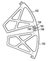
다른 실시예에 있어서, 지지 구조체는 단부에서 보았을 때 대체로 원형 형상이며, 각각의 개별 세그먼트는 적어도 하나의 가늘고 긴 통로를 갖는 대체로 쐐기 형상이다. 일 실시예에 있어서, 상기 쐐기 형상 세그먼트는 대체로 매끄러운 외측 가장자리를 지지하는 복수의 가늘고 긴 통로를 갖는 트러스이다.In another embodiment, the support structure is generally circular in shape as viewed from the end, and each individual segment is generally wedge-shaped with at least one elongated passage. In one embodiment, the wedge shaped segment is a truss having a plurality of elongated passages that support a generally smooth outer edge.
다른 실시예에 있어서, 성형 시스템은, 전술한(및 본 명세서에 기재된) 모듈식 지지 구조체를 갖는 맨드릴 몸체 및 대체로 폐루프 형상을 형성하는 복수의 개별 치형 세그먼트로부터 형성된 맨드릴면을 포함한다. 상기 맨드릴면은 상기 맨드릴 몸체로부터 반경 방향 외측으로 배향된 치형부에 의해 상기 맨드릴 몸체의 외부면에 대하여 밀접하게 끼워맞춤된다. 또한, 성형 시스템은, 상기 지지 구조체 내에서 중심이 맞춰진 코어 및 대체로 폐루프 형상으로 형성되고, 상기 맨드릴면의 치형부에 대하여 반대 방향으로 연장되는 복수의 반경 방향으로 연장되는 치형부를 구비하는 보조 구성요소를 포함한다. 조립되면, 상기 맨드릴면 및 보조 구성요소는 대체로 동심이며, 성형 공정 동안 벨트가 형성되는 갭을 그들 사이에 형성한다.In another embodiment, the forming system includes a mandrel body having a modular support structure as described above (and described herein) and a mandrel face formed from a plurality of individual toothed segments forming a generally closed-loop shape. The mandrel surface is closely fitted against the outer surface of the mandrel body by a tooth portion oriented radially outwardly from the mandrel body. The forming system further includes a secondary structure having a core centered in the support structure and a plurality of radially extending teeth formed in a generally closed loop shape and extending in opposite directions relative to the teeth of the mandrel surface Element. Once assembled, the mandrel surface and auxiliary components are generally concentric, forming a gap therebetween in which the belt is formed during the molding process.
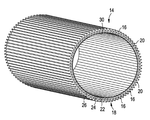
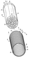
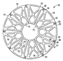
도 1은 본 발명의 맨드릴면의 일 실시예의 정면 사시도이다.
도 2는 도 1의 맨드릴면의 맨드릴 세그먼트의 정면 사시도이다.
도 3은 대안적인 맨드릴면의 단면도이다.
도 4는 도 3의 맨드릴면의 맨드릴 세그먼트의 단면도이다.
도 5는 도 2의 맨드릴 세그먼트를 사용하여 형성된 대안적인 맨드릴면의 단면도이다.
도 6은 도 1의 맨드릴면이 모듈식 지지 구조체를 갖는 맨드릴 몸체 상에 장착되는 것을 도시하는 정면 사시도이다.
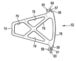
도 7은 벨트가 그 사이에 위치된 양생 슬리브와 관련하여 도시된 도 6의 맨드릴의 단면도이다.
도 8a 내지 도 8c는 도 7의 양생 슬리브를 형성하기 위해 이용될 수 있는 일련의 단계들을 도시한다.
도 9는 도 7의 양생 슬리브를 형성하는 대안적인 방법을 도시한다.
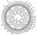
도 10은 맨드릴 몸체의 모듈식 지지 구조체의 일 실시예의 단면도이다.
도 11은 도 10의 모듈식 지지 구조체의 하나의 세그먼트의 단면도이다.
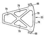
도 12a 및 도 12b는 도 10과 유사한 모듈식 지지 구조체의 개별 세그먼트의 대안적인 실시예의 단면도이다.
도 13은 독립된 커넥터에 의해 연결된 모듈식 지지 구조체의 두 개의 개별 세그먼트의 단면도이다.
도 14a 내지 도 14c는 도 13의 지지 세그먼트들을 연결하는 독립된 커넥터의 대안적인 실시예의 사시도이다.
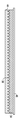
도 15는 모듈식 지지 구조체의 일 실시예의 지지 세그먼트들의 단면도이다.
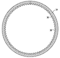
도 16은 도 15의 하나의 지지 세그먼트의 사시도이다.
도 17은 도 15의 지지 세그먼트들을 정렬시키기 위한 단부 캡의 사시도이다.
도 18은 벨트가 그 사이에 위치된 양생 슬리브와 관련하여 도시된 도 15 및 도 17의 지지 세그먼트들과 단부 캡을 갖는 맨드릴의 단면도이다.1 is a front perspective view of one embodiment of a mandrel face of the present invention.
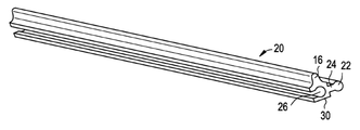
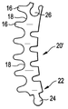
Figure 2 is a front perspective view of the mandrel segment of the mandrel surface of Figure 1;
3 is a cross-sectional view of an alternate mandrel surface.
Figure 4 is a cross-sectional view of the mandrel segment of the mandrel surface of Figure 3;
Figure 5 is a cross-sectional view of an alternate mandrel surface formed using the mandrel segment of Figure 2;
Figure 6 is a front perspective view showing the mandrel surface of Figure 1 mounted on a mandrel body having a modular support structure.
Figure 7 is a cross-sectional view of the mandrel of Figure 6 shown with respect to the curing sleeve with the belt therebetween.
Figures 8A-8C illustrate a series of steps that may be used to form the curing sleeve of Figure 7.
Figure 9 shows an alternative method of forming the curing sleeve of Figure 7.
10 is a cross-sectional view of one embodiment of a modular support structure for a mandrel body.
Figure 11 is a cross-sectional view of one segment of the modular support structure of Figure 10;
12A and 12B are cross-sectional views of alternative embodiments of discrete segments of a modular support structure similar to that of FIG.
Figure 13 is a cross-sectional view of two separate segments of a modular support structure connected by separate connectors.
14A-14C are perspective views of an alternative embodiment of an independent connector connecting the support segments of FIG.
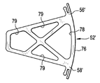
15 is a cross-sectional view of support segments of one embodiment of a modular support structure.
Figure 16 is a perspective view of one support segment of Figure 15;
Figure 17 is a perspective view of an end cap for aligning the support segments of Figure 15;
Figure 18 is a cross-sectional view of a mandrel having the support segments and end caps of Figures 15 and 17 shown with respect to the curing sleeve with the belt therebetween.
도 7에 도시된 바와 같이, 본 발명의 일 실시예에 있어서, 성형 시스템(11)은 벨트 상에 내측 홈과 외측 홈을 구비하는 대체로 원통형의 벨트(32)를 형성하거나 또는 성형하는 형태이다. 벨트(32)는, 벨트(32)의 내측 홈들을 형성하는 맨드릴 시스템(mandrel system) 또는 성형 구성요소(10)과 벨트(32)의 외측 홈들을 형성하는 양생 슬리브(curing sleeve) 또는 자켓(34) 사이에 위치된다. 맨드릴 시스템(10)은 복수의 맨드릴 하부 세그먼트(52)로 형성된 대체로 원통형의 맨드릴 몸체(12) 및 대체로 폐루프 형상으로 형성되고 맨드릴 몸체(12)의 원주 둘레로 연장되는 대체로 원통형의 맨드릴면 또는 구성요소(14)을 포함한다. 맨드릴면(14)은 반경 방향-외측으로 연장되는 복수의 돌출부/치형부(16) 및 각각의 치형부(16) 사이에 위치된 반경 방향-내측으로 연장되는 오목부(18)들을 구비한다.As shown in Figure 7, in one embodiment of the present invention, the forming
맨드릴면(14)은 해제 가능하게 함께 서로 맞물린 복수의 맨드릴 세그먼트(20)를 포함한다. 특히, 도 1 및 도 2에 도시된 실시예에 있어서, 각각의 맨드릴 세그먼트(20)는 인접한 맨드릴 세그먼트(20)에 해제 가능하게 서로 맞물리도록 구성된 록킹부(22)를 포함한다. 특히, 도시된 실시예에 있어서, 각각의 맨드릴 세그먼트(20)는 수형부(male portion)(24) 및 이 수형부에 대응하는 개구부 또는 암형부(female portion)(26)를 구비하며, 이들 부분들의 각각의 형상은 대체로 원형 또는 구형상(bulbous)이다. 각각의 맨드릴 세그먼트(20)의 각각의 수형부(24)는 인접한 맨드릴 세그먼트(20)를 함께 서로 맞물기 위해 인접한 맨드릴 세그먼트(20)의 암형부(26)에 수용될 수 있다. 원형 형상의 수형부(24)와 암형부(26)는 결합된 맨드릴 세그먼트(20)들을 서로에 대해 시프트/피봇시킬 수 있으며, 수형부(24)와 암형부(26)는 원형 이외의 다양한 다른 형상 및 구성들을 가질 수 있다.The
맨드릴 세그먼트(20)들로부터 맨드릴면(14)을 형성시키기 위해, 각각의 수형부(24)는, 맨드릴 세그먼트(20)들이 대체로 축방향으로 정렬될 때까지 인접한 맨드릴 세그먼트(20)의 암형부(26) 내로 축방향으로 슬라이딩된다. 그 후, 도 1에 도시된 바와 같이, 대체로 폐루프 형상이 형성될 때까지 추가의 맨드릴 세그먼트(20)들이 축방향으로 장착된다.Each of the
맨드릴면(14)은 단부에서 보았을 때 대체로 원형 형상을 가지며, 각각의 록킹부(22)(수형부(24)/암형부(26))는 맨드릴면의 원주 단면에 위치되거나 또는 이 단면에 인접하여 위치된다. 이 위치지정은, 후술하는 바와 같이, 벨트 성형 공정 또는 맨드릴 몸체(12)에 대한 맨드릴면(14)의 부착을 방해하지 않는 것을 보장한다.The
도 1 및 도 2에 도시된 실시예들에 있어서, 각각의 맨드릴 세그먼트(20)는 비교적 짧은 원주 길이를 가지며, 또한 반경 방향-외측으로 연장되는 단일의 치형부(16)를 포함한다. 그러나, 각각의 맨드릴 세그먼트(20)는 다양한 다른 개수의 치형부(16)를 포함할 수 있다. 예를 들면, 도 3 및 도 4에 도시된 실시예에 있어서, 각각의 맨드릴 세그먼트(20')는 도 1 및 도 2의 실시예와 비교하여, 6개의 치형부(16)를 포함하는 더 긴 원주 길이를 갖는다. 그러나, 각각의 맨드릴 세그먼트(20, 20')는 임의의 다양한 개수의 치형부(16)를 포함할 수 있다는 것을 이해하여야 한다. 더욱이, 어떤 경우들에 있어서, 일부 맨드릴 세그먼트(20)들은 비교적 짧을 수 있으며, 또한 치형부를 구비하지 않을 수 있다. 이러한 맨드릴 세그먼트들은 치형-베어링(tooth-bearing) 맨드릴 세그먼트들을 연결하기 위한 스페이서(spacer) 또는 커넥터로서 작용할 수 있다.In the embodiments shown in Figures 1 and 2, each
도 1은, 도 2의 비교적 많은 개수의 맨드릴 세그먼트(20)로 구성된 맨드릴면(14)을 도시하는 것을 알 수 있다. 그러나, 맨드릴 세그먼트(20)의 개수, 특히 맨드릴면(14)은 원하는 바에 따라 변경될 수 있다. 예를 들면, 도 5는, 도 1의 맨드릴면(14)과 비교하여 더 작은 반경을 갖는 맨드릴면(14)을 형성하기 위해 더 작은 개수의 맨드릴 세그먼트(20)가 이용된 대안적인 실시예를 도시한다. 따라서, 맨드릴 세그먼트(20)의 모듈 특성은, 맨드릴면(14)이 매우 다양한 임의의 크기로, 한가지 예에 있어서, 약 1 인치 내지 약 6 인치 이상의 반경 범위를 갖는 크기로 조립될 수 있다는 것을 알 수 있을 것이다. 맨드릴 세그먼트(20)들의 반경 방향의 내측 가장자리(30)가 서로 결속되어 간섭을 일으킬 수 있다는 사실을 고려하여, 맨드릴면(14)은 그의 반경에 대해 하한을 가질 수 있다. 그러나, 보다 큰 맨드릴면(14)을 형성시키기 위해 추가의 맨드릴 세그먼트(20)들을 부가하고, 이론적으로 필요한 만큼의 큰 반경을 갖는 맨드릴면(14)을 형성시키는 것에 장애는 없다. 따라서, 맨드릴면(14)은 원하는 바에 따라 맨드릴 세그먼트(20)들을 부가/제거하는 것에 의해 직경을 변경시킬 수 있다. 그러나, 일부 경우들에 있어서, 맨드릴면(14)은 용접, 부착 브라켓에 의해, 또는 다른 야금적, 기계적 또는 다른 부착 방법들에 의해, 맨드릴 세그먼트(20)들을 함께 결합시키는 것에 의해 영구적으로 형성될 수 있다.It will be appreciated that FIG. 1 illustrates a
일 실시예에 있어서, 각각의 맨드릴 세그먼트(20)의 반경 방향 내측 가장자리(30)는 곡률 반경(radius of curvature)을 갖는다. 일부 경우들에 있어서, 맨드릴면(14)은 내측 가장자리(30)의 곡률 반경과 동일한 유효 내측 반경을 가질 수 있으며, 이에 따라 각각의 내측 가장자리(30)는 인접한 내측 가장자리(30)에 부드럽게 전이(transition)될 수 있다. 그러나, 전술한 논의에서 명백한 바와 같이, 맨드릴면(14)은 결합된 맨드릴 세그먼트(20)들의 곡률 반경과는 다른 유효 내측 반경을 가질 수 있으며, 이에 따라 내측 가장자리(30)는 오히려 다각형의 형태를 가질 수 있다.In one embodiment, the radially
도시된 실시예들에 있어서, 각각의 맨드릴면(14)은 실질적으로 동일한 크기와 형상을 갖는 복수의 맨드릴 세그먼트(20)로 구성될 수 있다. 그러나, 원하는 바에 따라, 도 2 및 도 4, 또는 다른 도면들에 도시된 맨드릴 세그먼트(20, 20')들의 혼합 및 조화(matching)를 포함하는 다른 크기 및/또는 형상의 맨드릴 세그먼트(20)들이 맨드릴면(14)을 형성하는데 이용될 수 있다. In the illustrated embodiments, each
각각의 맨드릴 세그먼트(20)는 금속, 특히 알루미늄, 알루미늄 합금 등과 같은 재료, 또는 다른 적절한 경질 및 내구성 재료의 압출 성형편(extruded piece)으로 제조될 수 있다는 것을 알 수 있을 것이다. 또한, 맨드릴면(14)이 조립될 때, 맨드릴면(14)은 대체로 원통형일 수 있으며, 또한 종래의 구동 벨트들을 형성하기에 적합한 비교적 긴 실린더를 제공하기 위해 이러한 실린더의 반경과 적어도 대략 동일한 축방향 길이, 또는 이러한 실린더 반경의 적어도 대략 1/4인 축방향 길이를 갖는다.It will be appreciated that each
원하는 형상과 특징을 갖는 맨드릴면(14)이 형성된 후에, 이 맨드릴면(14)은, 도 6에 도시된 바와 같이 맨드릴 몸체(12)에 결합될 수 있다. 맨드릴면(14)은 용접, 접착, 기계적 부착, 록킹 링의 사용, 리테이닝 링(retaining ring), 상호 맞물림 부착 등과 같은 폭넓은 메커니즘 또는 수단에 의해 맨드릴 몸체(12)에 결합될 수 있다. 도시된 실시예에서는, 맨드릴 몸체(12)는 대체로 원통형으로, 맨드릴면(14)을 그의 표면 상에서 밀접하게 수용하며, 이에 따라 맨드릴면(14)의 반경 방향 내측 면은 맨드릴 몸체(12) 위에 밀접하게 수용되어 이 맨드릴 몸체에 의해 지지된다. 도 6에 도시된 실시예에 있어서, 맨드릴 몸체(12)는 코어((core)(54)에 의해 선택적으로 지지된 복수의 개별 지지 세그먼트(52)들을 갖는 모듈식 지지 구조체(50)로서 도시되어 있다.After the
도 7에 도시된 바와 같이, 맨드릴 몸체(12)는 서로에 대하여 영구적으로 연결되거나 또는 해제 가능하게 연결될 수 있는 복수의 개별 지지 세그먼트(52)로 형성된다. 일 실시예에 있어서, 각각의 개별 지지 세그먼트(52)는 지지 구조체(50)를 형성하기 위해 사용된 다른 모든 개별 지지 세그먼트(52)들과 대체로 동일한 크기 및 형상을 갖는다. 다른 실시예에 있어서, 교호적인 또는 주기적인(periodic) 개별 지지 세그먼트(52)들은 다른 크기 및/또는 형상들을 가질 수 있다. 크기 및 형상에 상관없이, 각각의 개별 지지 세그먼트(52)는 제1 커넥터(56) 및 제2 커넥터(58)를 포함한다. 도 7 및 도 10에 도시된 실시예에 있어서, 제1 커넥터(56) 및 제2 커넥터(58)는 각각의 개별 세그먼트(52)에서 다르다. 세그먼트(52)들은 전술한 형상에 한정되는 것은 아니며, 도 12a 및 도 12b에 도시된 바와 같이, 제1 개별 세그먼트(52')의 제1 커넥터(56') 및 제2 커넥터(58')는 동일한 형상이고, 제2 개별 세그먼트(53)의 제1 커넥터(66) 및 제2 커넥터(68)도 동일 형상이지만 상기 커넥터(56', 58')들과는 다른 형상을 가질 수 있다. 이러한 형태의 모듈식 맨드릴 몸체(12)는, 개별 지지 세그먼트(52)들의 외부면(70)에 의해 형성된 폐루프 형상의 전체적인 기하학적 형상을 변경시키도록, 개별 지지 세그먼트(52 또는 52', 53)들의 개수를 증가시키거나 또는 감소시킬 수 있다.As shown in FIG. 7, the
도 10 및 도 11을 참조하면, 제1 커넥터(56)는 암형부(57)를 포함하고, 제2 커넥터(58)는 수형부(59)를 포함하며, 이들 암형부와 수형부는 대체로 서로 결합(mateable)될 수 있는 원형 또는 구형상이다. 각각의 지지 세그먼트(52)의 각각의 수형부(59)는 인접한 지지 세그먼트들을 함께 연결시키기 위해 인접한 지지 세그먼트(52)의 암형부(57)에 수용될 수 있다. 또한, 제2 커넥터(58)는 수형부(59)로부터 반경 방향 외측으로 이격된 돌출부(overhang)(60)를 포함하며, 이에 따라 수형부와 돌출부 사이에 홈(61)이 형성된다. 암형부(57)는 내측 레일(inner rail)(62)과 외측 레일(outer rail)(64)에 의해 형성된다. 조립될 때, 외측 레일(64)은 제2 커넥터(58)에 의해 형성된 홈(61)에 수용된 텅(tongue)이다. 인접한 지지 세그먼트(52)들의 이러한 추가적인 상호연결은 지지 구조체(50)에 강성을 추가한다. 수형부 및 암형부(59, 57)의 원형 또는 구형상은, 결합된 맨드릴 세그먼트(20)들을 서로에 대해 시프트/피봇시킬 수 있지만, 돌출부(60)에 의해 허용된 범위로만 시프트/피봇된다. 수형부 및 암형부(59, 57)는 원형으로 도시되어 있지만, 이들은 다양한 다른 형상 및 구성들을 가질 수 있다.10 and 11, the
지지 구조체(50)는 단부에서 보았을 때 대체로 원형의 형상을 가진다. 도 10에 가장 잘 나타낸 바와 같이, 각각의 개별 지지 세그먼트(52)는 곡률 반경을 갖는 반경 방향 내측 가장자리(74) 및 곡률 반경을 갖는 반경 방향 외측 가장자리(76)를 구비한 대체로 쐐기형상이다. 각각의 개별 지지 세그먼트(52)의 외측 가장자리(76)는 조립될 때 맨드릴 몸체(12)의 외부면(70)의 원주의 원호를 형성한다. 이 원호는 제1 커넥터(56)를 구비하는 그의 제1 단부에서 종단되고, 그리고 제2 커넥터(58)를 구비하는 그의 제2 단부에서 종단된다. 제1 및 제2 커넥터(56, 58)들은 외측 가장자리(76)에 위치하거나 또는 이 외측 가장자리에 인접하여 위치되며, 이는 커넥터들이 벨트 성형 공정 또는 지지 구조체(50)에 대한 맨드릴면(14)의 부착을 방해하지 않는 것을 보장한다. 각각의 개별 세그먼트의 원호는 360°에서의 임의의 분할, 예를 들어 외부면(70)의 원주의 대략 120°까지로 형성될 수 있다.The
대체로 쐐기 형상의 지지 세그먼트(52)들은 맨드릴 몸체(12)의 중앙 길이방향 축(A)(도 6 참조)에 대체로 평행하게 연장되는 적어도 하나의 가늘고 긴 통로(elongate passage)(78)(도 10 내지 도 12 참조)를 포함한다. 일 실시예에 있어서, 대체로 쐐기 형상의 지지 세그먼트(52)들은 중앙 길이방향 축(A)에 대체로 평행하게 연장되는 복수의 가늘고 긴 통로를 포함한다. 복수의 가늘고 긴 통로가 존재하는 경우, 지지 세그먼트(52)들은 그의 외측 가장자리(76)와 같은 원호를 갖는 트러스(truss)로서 묘사될 수 있다. 이들 가늘고 긴 통로(78, 79)들의 하나 이상의 존재는 성형 공정, 예를 들어 동력전달 벨트들을 성형할 때 가열 및 냉각 사이클 동안의 열전달을 개선시키며, 또한 더 짧은 처리 시간으로 시간 및 비용을 절감할 수 있다. 가늘고 긴 통로(78, 79)들은 또한 성형된 제품의 더욱 균일한 경화(curing)를 제공한다.The generally wedge shaped
흥미롭게는, 도 10에 도시된 바와 같이, 인접한 지지 세그먼트(52)들이 그들의 각각의 외측 가장자리(76)들에서 연결될 때, 그들의 각각의 내측 가장자리들은 서로로부터 떨어져 유지되며, 이에 의해 갭(gap)이 생성된다. 이러한 갭은 코어의 외부면이 스플라인(spline)과 같은 코어(core)(54)(도 6 참조)로부터의 표면 형상(55)을 수용할 수 있다. 일 실시예에 있어서, 코어(54)는 하나의 개별 지지 세그먼트(52)에 영구적으로 결합될 수 있다. 다른 실시예에 있어서, 코어는 복수의 지지 세그먼트(52)에 제거가능하게 결합될 수 있으며, 성형 제조 공정 중에 필요에 따라 부가 및/또는 제거될 수 있다. 일부 경우들에 있어서는, 지지 세그먼트(52)들은 용접, 부착 브라켓에 의해, 또는 다른 야금적, 기계적 또는 다른 부착 방법들에 의해, 영구적으로 함께 결합될 수 있다.Interestingly, as shown in FIG. 10, when
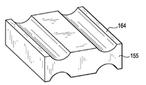
도 13의 대안적인 실시예에 있어서, 개별 지지 세그먼트(152)들은 독립된 커넥터(155)를 통해 서로에 대해 연결될 수 있다. 도 14a 내지 도 14c에 도시된 바와 같이, 독립된 커넥터(155)는 두 개의 수형 단부(male end)(159)를 갖는 대체로 도그-본 형상의 커넥터(dog-bone shaped connector)(162, 162', 164)일 수 있다. 수형 단부(159)들은 개별 지지 세그먼트(152)의 암형부(156)들에 영구적으로 또는 해제 가능하게 연결될 수 있다. 영구적인 결합은 브레이징, 용접 또는 접착을 포함하지만, 이러한 부착들에 한정되는 것은 아니다. 독립된 커넥터가 두 개의 암형 단부를 포함하는 것도 가능하며, 또한 개별 지지 세그먼트들이 이들 암형 단부들에 결합될 수 있는 수형부들을 포함하는 것도 가능하다. 다른 실시예에 있어서, 독립된 커넥터는 또한 인접한 개별 지지 세그먼트들을 연결시키기 위해 하나의 수형부와 하나의 암형부를 포함할 수 있다. 13, the
일 실시예에 있어서, 도그-본 형상 커넥터(162)(도 14a 참조)는 개별 지지 세그먼트(152)와 대체로 같은 길이이다. 다른 실시예에 있어서, 도그-본 형상 커넥터(162')(도 14b 참조)는 대체로 짧은 연결 스트립이다. 커넥터(162')는 약 0.5 인치 내지 약 6 인치의 길이일 수 있다. 도그-본 커넥터(162, 162')들은 대체로 원형 잎모양 단부(rounded lobed end)들을 갖는 것으로 도시되어 있다. 반대로, 도 14c의 도그-본 커넥터(164)는 대체로 사각형 모양 단부(squared-off end)들을 갖는다. 도그-본 커넥터(162, 162', 164)들은 독립된 커넥터(155)의 형상에 따라 제한될 필요는 없으며, 단지 예시적으로 나타낸 것이다. In one embodiment, the dog-and-bone connector 162 (see FIG. 14A) is substantially the same length as the
일 실시예에 있어서, 맨드릴 몸체(12)를 형성하기 위해, 개별 지지 세그먼트(52)를 정렬시키도록 코어(54)(도 6 참조)가 제공되며, 각각의 지지 세그먼트(52)는 대체로 매끄러운 외부면(70)을 형성하도록 제1 및 제2 커넥터(56, 58)를 함께 슬라이딩시키는 것에 의해 그의 이웃하는 세그먼트에 대해 서로 슬라이딩 맞물린다. 제2 커넥터(58)는, 지지 세그먼트(52)들이 대체로 축방향으로 정렬될 때까지 인접한 지지 세그먼트(52)의 제1 커넥터(56) 내로 축방향으로 슬라이딩될 수 있다. 그 후, 도 6 및 도 10에 도시된 바와 같이, 대체로 폐루프 형상이 형성될 때까지 추가의 지지 세그먼트(52)들이 유사한 방식으로 축방향으로 장착된다.In one embodiment, to form the
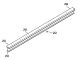
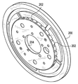
도 15 내지 도 17을 참조하면, 맨드릴 몸체(12)는 개별 지지 세그먼트들을 정렬(및 개별 지지 세그먼트들의 정렬을 유지)시키기 위해, 코어에 부가하여 또는 코어(54)(도 16 참조)의 대안으로서, 단부 플레이트 또는 캡(cap)(200)(도 17 및 도 18 참조)을 사용하여 형성될 수 있으며, 특히, 키-포함 지지 세그먼트(key-containing support segment)(252)(도 15 참조)가 단부 캡(200)의 리셉터클(receptacle)(202) 내로 맞추어진다. 도 15에는 키-포함 지지 세그먼트(252)들이 대체로 T자형 몸체(290)를 갖는 것으로 도시되어 있지만, 쐐기형, 트러스트형 또는 다른 형상의 몸체를 갖는 전술한 개별 지지 세그먼트(52, 152)들 중 어느 것은 단부 캡으로의 연결을 위한 키(key)(253)를 포함할 수 있다. 단부 플레이트 또는 캡(200)(도 17 참조)은, 세그먼트들을 맨드릴면(14) 및 성형 시스템(11)의 다른 구성요소들을 지지할 수 있는 폐루프 구조로 형성시키기 위해, 전형적으로 개별 지지 세그먼트(252)들의 종단(terminus)에서 중심이 맞춰진다. 바람직하게는, 맨드릴 몸체(12)(도 18 참조)는 개별 지지 세그먼트(252)들의 대향된 종단부(terminus end)(282, 284)(도 16 참조)에서 두 개의 단부 캡(200)을 포함한다. 단부 캡(200)들은 전형적으로, 내측 방향으로의 힘, 일반적으로 대향 단부 캡을 향하는 방향으로의 힘에 의해 양쪽 방향으로 편향되거나 또는 유지된다. 단부 캡(200)들은 내측방향으로 향하는 힘을 부여하기 위한 로드(rod), 볼트, 또는 스프링을 수용하는 보어(bore)(204)를 포함하거나, 또는 내측 방향으로 향하는 힘을 부여하는 클램핑 메커니즘(clamping mechanism)의 정렬 핀부(alignment pin portion)를 수용할 수 있다.Referring to Figures 15-17, the
도 15, 도 16 및 도 18의 실시예에 있어서, 키(253)는 일반적으로 키-포함 지지 세그먼트(252)의 길이를 주행하는 리브(rib)이다. 도시된 바와 같이, 리브는 키-포함 지지 세그먼트(252)의 대체로 T자형 몸체(190)의 베이스(288)의 저부면(bottom surface)(286) 상에 위치된다. 키(253)는 저부면(286) 상에 위치되는 것에 한정되는 것은 아니며, 키-포함 지지 세그먼트(252)들 중 어느 하나의 표면 또는 하나 이상의 표면 상에 위치될 수 있다. 역으로, 단부 캡(200)은 복수의 키를 포함할 수 있으며, 각각의 개별 지지 세그먼트(252)는 리셉터클을 포함할 수 있다.In the embodiment of Figures 15, 16 and 18, the key 253 is a rib that generally runs the length of the key-containing
도 15의 키-포함 지지 세그먼트(252)들은 이들이 단부 캡(200)에 대해 키설정(keyable)이 가능하기 때문에, 복잡하지 않은 부착 수단(attachment means)(256, 258)들을 구비한다. 각각의 키-포함 지지 세그먼트(252)는 베이스(288), 중앙 암(center arm)(292) 및 원호형 상부(arched top)(294)를 포함하는 대체로 T자형의 빔 본체(290)를 구비한다. 원호형 상부(294)는 제1 커넥터(256)를 구비하는 제1 단부(230) 및 제2 커넥터(258)를 구비하는 제2 단부(232)에서 종단된다. 제1 및 제2 커넥터(256, 258)는 내측 가장자리(277)에 위치되거나 또는 내측 가장자리에 인접하여 위치되며, 이 내측 가장자리는, 커넥터들이 벨트 성형 공정 또는 지지 구조체(50)에 대한 맨드릴면(14)(도 6 참조)의 부착을 방해하지 않는 것을 보장한다. 각각의 개별 세그먼트의 원호는 외부면(270)의 원주의 약 120°까지 형성되도록 360°에서의 임의의 분할로 선택될 수 있다. 도 15를 참조하면, 제1 커넥터(256)는 세그먼트(252)들이 조립될 때, 중앙 길이방향 축(A)을 향하여 내측으로 돌출하는 대체로 직선인 플랜지(flange)(259)를 포함하고, 제2 커넥터(258)는 세그먼트(252)들이 조립될 때, 단면으로 보았을 때, 중앙 길이방향 축(A)을 향하여 돌출하고 또한 내측으로 돌출하는 대체로 J자형 플랜지(257)를 포함한다. 또한, 조립될 때, 제1 키-포함 지지 세그먼트(252)의 대체로 직선인 플랜지(259)는 인접한 키-포함 지지 세그먼트(252)의 대체로 J자형 플랜지(257)에 수용되어, 양쪽 세그먼트들의 외부면(270)들이 정렬된다.The key-containing
단부 플레이트(200)(도 17 참조)는, 맨드릴면(14)이 단부 플레이트(들)(200)에 대하여 종단되는 충분한 크기의 직경을 가질 수 있다. The end plate 200 (see FIG. 17) may have a sufficient diameter that the
조립될 때, 맨드릴 몸체(12)는 형성되는 벨트의 제조 공정을 위해 임의의 원하는 길이를 가질 수 있다. 유사하게, 맨드릴은 (외부면이 원형인 경우) 형성되는 벨트에 대하여 직경과 같은 임의의 실제적인 외경을 가질 수 있다. 일 실시예에 있어서, 형성되는 벨트는 3 인치에서 최대 약 24 인치의 반경을 가질 수 있다. When assembled, the
각각의 개별 지지 세그먼트(52, 152, 162, 252) 및/또는 독립된 커넥터(155)는 금속, 특히 알루미늄, 알루미늄 합금 등과 같은 재료, 또는 다른 적절한 경질 및 내구성 재료의 압출 성형편일 수 있다. 압출 성형편들은 제조가 쉽고, 비용 효과적인 제품을 위한 재현성(reproducibility)을 제공한다. 원하는 바에 따라, 원하는 최종 드럼 크기에 기초한 다른 크기 및/또는 형상의 지지 세그먼트(52)들이 압출될 수 있으며, 지지 구조체(50)를 형성하기 위해 사용될 수 있다. Each
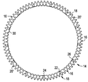
지지 구조체(50)와 코어(54)를 포함하거나 또는 지지 구조체(50)와 단부 캡(들)(200)을 포함하는 맨드릴 몸체(12) 및 맨드릴면(14)이 도 17 또는 도 18에 도시된 바와 같이 유닛으로 조립되고 나면, 맨드릴 시스템(10)은 동력 전달 벨트들과 같은 구동 벨트들을 형성하기 위해 사용될 수 있다. 특히, 벨트는 고무, 고무 플라이(rubber ply), 빌트-업 고무 플라이 등과 같은 재료(32)를 맨드릴면(14)에 대하여 위치시키는 것에 의해 형성될 수 있다. 그 후, 적절한 슬리브, 자켓 등과 같은 양생 슬리브(34)는 맨드릴 시스템(10)과 동축 배치로 재료(32) 둘레에 위치되고, 재료(32)가 위치되는 그들 사이에 갭을 형성한다. 도시된 실시예에 있어서, 슬리브(34)는 반경 방향 내측으로 연장되는 복수의 치형부(teeth)(36)를 포함한다. 양생 슬리브(34)는 외부 압력(또는 다른 적절한 힘)을 받으며 위치되고, 이에 의해 슬리브(34)의 치형부(36)를 재료(32) 내로 밀어 넣고, 또한 재료(32)를 치형부(16)에 대하여 밀어 넣고, 그리고 맨드릴면(14)의 홈(groove) 내로 밀어 넣는다. 재료를 원통형 벨트(32)의 원하는 형상으로 형성시키기 위해 열 및/또는 추가 압력이 적용될 수 있다.A
충분한 열과 압력이 적용되고, 벨트(32)가 원하는 형상으로 형성되면, 양생 슬리브(34)는 제거되고 벨트(32)는 맨드릴면(14)으로부터 축방향으로 슬라이딩 된다. 얻어진 구동 벨트(32)는 대체로 원통형일 수 있으며, 맨드릴면(14)에 의해 형성된 반경 방향 내측 치형부/홈의 세트 및 양생 슬리브(32)에 의해 형성된 반경 방향 외측 치형부/홈의 세트들을 구비한다. 그러나, 본 명세서에서 제공되는 설명 및 예시는 외부적으로 홈이 형성된 표면을 갖는 벨트(32)를 예시하지만, 이러한 벨트(32)는 내측 홈과 매끄러운 외측 면만을 가지거나, 또는 외측 홈과 매끄러운 내측 면만을 가지거나, 또는 본 명세서에서 예시된 것 이외의 다른 형상을 가질 수 있다.When sufficient heat and pressure is applied and the
도 8a 내지 도 8c 및 도 9에 도시된 바와 같이, 맨드릴면(14)은 전술한 맨드릴면이거나 또는 이 맨드릴면과 유사하며, 양생 자켓 또는 슬리브(34), 또는 양생 슬리브 몰드(46)를 형성하는데 사용될 수 있다. 도 8a 내지 도 8c에 도시된 실시예에 있어서는, 플레이트/성형 시스템(38)이 제공되며, 전술한 맨드릴 시스템(10)과 유사한 방식으로 복수의 세그먼트(20)(및/또는 세그먼트(20'))로 구성된다. 특히, 각각의 세그먼트(20)는 록킹부(22)/수형부(24)/암형부(26)를 구비할 수 있으며, 전술한 맨드릴 세그먼트들과 동일한 방식 또는 유사한 방식으로 결합/해제될 수 있다. 8A-8C and 9, the
플레이트(38)는, 슬리브(34)를 형성하기 위해 사용되는 순번에서 슬리브 몰드(44)를 형성하기 위해 사용될 수 있다. 이와 같은 슬리브 몰드(44)를 형성하기 위해, 코드(cord) 또는 섬유(fabric)가 없는 매우 두꺼운 두께 고무(heavy gauge rubber)와 같은 재료가 슬리브 몰드(44)를 형성하는데 사용되며, 이어서 이 재료는 플레이트(38) 상에 위치되고 프레스 플레이트(40)에 의해 플레이트(38)와 접촉되도록 압축된다. 그 후, 슬리브 몰드(44)는 플레이트(38, 40)들로부터 제거된다. 이어서, 슬리브(34)를 형성하기 위해 사용된 재료가 슬리브 몰드(44) 상에 위치되고 프레스 플레이트(46)에 의해 슬리브 몰드(44)와 접촉되도록 압축된다(도 8b 참조). 그 후, 성형된 슬리브 재료(34)가 제거되고, 도 8c에 도시된 바와 같이 슬리브(34)를 형성하기 위해 폐루프 형상으로 형성된다. 이어서, 슬리브(34)는, 도 7에 도시된 바와 같이 벨트(32)의 외측 홈을 형성하기 위해 사용될 수 있다. The
도 9에 도시된 바와 같이, 대안적인 실시예에 있어서는, 슬리브(34)는 맨드릴 시스템/성형 구성요소(42)에 의해 형성된다. 이 경우에 있어서, 슬리브(34)의 외측 면이 그 안에 형성된 임의의 홈/치형부를 구비하지 않는 것을 제외하고는, 도 7에 도시되고 전술한 벨트를 형성하기 위한 시스템과 유사한 방식으로 맨드릴 시스템(42)에 대하여 원통형 형상으로 형성된다. 그 후, 도 9에 도시된 슬리브(34)는 맨드릴(42)로부터 제거되고, 도 7에 도시된 바와 같이 벨트(32)의 외측 홈을 형성하기 위해 사용될 수 있다. As shown in FIG. 9, in an alternative embodiment, the
도 9에 도시된 성형 구성요소(24)은 각각이 복수의 치형부(16)를 갖는 세그먼트(20')들로 구성되어 있지만, 성형 구성요소는 또한 단일 치형부를 갖거나 또는 이러한 치형부를 조합시킨 세그먼트(20)들로 구성될 수도 있다. 유사하게, 도 8a에 도시된 성형 구성요소(38)은 다양한 형태의 세그먼트(20, 20')들로 구성될 수 있다. 본 명세서에 도시된 성형 구성요소들은 반경 방향으로 외측으로 연장되는 치형부(16)를 구비하지만, 원하는 바에 따라, 반경 방향으로 내측으로 연장되는 치형부(16)를 갖는 성형 구성요소가 또한 형성되고 이용될 수 있다는 것을 이해하여야 한다.The forming
따라서, 본 명세서에 기재된 성형 구성요소(14, 38, 42, 50)들은 쉽게 제조되고 조립될 수 있다는 것을 알 수 있을 것이다. 모듈식 형상은, 성형 구성요소(14, 38, 42, 50)들이 복수의 세그먼트(20, 20', 52, 152, 252)를 형성하는 것을 가능하게 하고, 각각의 세그먼트는 비교적 작은 단면을 갖는 압출품 형상으로 제조될 수 있기 때문에 제조를 비교적 쉽게 할 수 있다. 성형 구성요소(14, 38, 42, 50)의 모듈 특성은 또한 성형 구성요소들을 다양한 형상으로 빠르고 쉽게 조립하는 것을 가능하게 한다. 또한, 시스템은 세그먼트(20)들의 수리 및/또는 교환을 쉽게 할 수 있으며, 이에 의해 세그먼트(20)는 접근 및/또는 교환을 위해 설치 위치로부터 쉽게 슬라이딩 될 수 있다. 마지막으로, 본 명세서에 기술된 시스템은 더 우수한 성형 결과들을 제공하는 금속으로 성형 구성요소, 특히 지지 세그먼트(52)에 대하여 더 짧은 처리 시간을 위한 더 나은 열전달 및 성형된 제품의 더욱 균일한 양생을 갖는, 성형 구성요소들을 형성시키는 것을 가능하게 한다.Thus, it will be appreciated that the
본 발명의 상세한 설명은 어떤 실시예들을 참조하여 기술하였지만, 본 발명명의 범위를 벗어나지 않고 다양한 변경 및 변형이 가능하다는 것을 인식하여야 한다.Although the present invention has been described with reference to certain embodiments, it should be understood that various changes and modifications may be made without departing from the scope of the present invention.
Claims (21)
상기 개별 세그먼트의 수는 상기 폐루프 형상의 전체적인 기하학적 형상을 변경시키기 위해 증가될 수 있거나 또는 감소될 수 있는, 성형 시스템용 맨드릴. Comprising a support structure formed in a generally closed loop shape and composed of a plurality of discrete segments joined together,
Wherein the number of discrete segments can be increased or reduced to change the overall geometric shape of the closed loop shape.
상기 복수의 개별 세그먼트의 각각의 개별 세그먼트는 영구적으로 함께 결합되거나, 또는 적어도 하나의 개별 세그먼트는 인접한 개별 세그먼트와 해제가능하게 연결될 수 있거나 또는 인접한 개별 세그먼트로부터 제거가능한 구성인, 성형 시스템용 맨드릴. The method according to claim 1,
Wherein each individual segment of the plurality of discrete segments is permanently joined together, or at least one discrete segment is releasably connectable with an adjacent discrete segment or is removable from an adjacent discrete segment.
상기 복수의 개별 세그먼트는 하나의 개별 세그먼트가 인접한 구성요소에 대하여 대체로 축방향으로 슬라이딩하는 것에 의해 서로 슬라이딩 결합될 수 있는, 성형 시스템용 맨드릴. The method according to claim 1,
Wherein the plurality of discrete segments are capable of sliding engagement with one another by having one discrete segment slide generally axially with respect to adjacent components.
상기 지지 구조체는 대체로 원통형이며, 단부에서 보았을 때 대체로 원형 형상을 가지며,
각각의 개별 세그먼트는 대체로 쐐기 형상인, 성형 시스템용 맨드릴. The method according to claim 1,
The support structure is generally cylindrical and has a generally circular shape when viewed at its end,
Each individual segment being generally wedge-shaped.
각각의 개별 세그먼트는 제1 커넥터 및 제2 커넥터를 구비하며,
상기 제1 및 제2 커넥터는 동일하거나 또는 다르며,
각각의 개별 세그먼트의 각각의 제1 커넥터는 인접한 개별 세그먼트의 제2 커넥터에 해제가능하게 연결될 수 있는, 성형 시스템용 맨드릴. The method according to claim 1,
Each individual segment having a first connector and a second connector,
Wherein the first and second connectors are the same or different,
Each first connector of each discrete segment being releasably connectable to a second connector of an adjacent discrete segment.
대체로 쐐기 형상의 각각의 개별 세그먼트는 곡룰 반경을 갖는 내측 가장자리 및 곡률 반경을 갖는 외측 가장자리를 구비하는, 성형 시스템용 맨드릴. 6. The method of claim 5,
Wherein each individual segment of the generally wedge-shaped portion has an inner edge having a curvature radius and an outer edge having a radius of curvature.
대체로 쐐기 형상의 각각의 개별 세그먼트는 외측 가장자리를 지지하는 하나 이상의 가늘고 긴 통로를 갖는 구조적 기하학적 형상을 갖는, 성형 시스템용 맨드릴. 6. The method of claim 5,
Wherein each individual segment of the generally wedge-shaped portion has a structural geometric shape having one or more elongated passages for supporting an outer edge thereof.
상기 제1 및 제2 커넥터는 다르며,
상기 제1 커넥터는 암형부를 포함하고, 상기 제2 커넥터는 수형부를 포함하는, 성형 시스템용 맨드릴. 6. The method of claim 5,
The first and second connectors are different,
Wherein the first connector comprises a female portion and the second connector comprises a male portion.
상기 제2 커넥터는 상기 수형부로부터 반경 방향 외측으로 이격된 돌출부를 더 포함하고, 이에 따라 상기 수형부와 돌출부 사이에 홈이 형성되며,
상기 암형부는 내측 레일 및 외측 레일을 포함하며,
상기 외측 레일은 상기 홈 내에 수용된 텅인, 성형 시스템용 맨드릴.9. The method of claim 8,
Wherein the second connector further comprises a protrusion spaced radially outwardly from the male part so that a groove is formed between the male part and the protrusion,
Wherein the female part includes an inner rail and an outer rail,
Wherein the outer rail is received within the groove.
상기 제1 및 제2 커넥터는 개개의 개별 세그먼트에서는 동일하지만, 인접한 개별 세그먼트 상의 제1 및 제2 커넥터와는 다르며, 이들 제1 및 제2 커넥터에 결합될 수 있는, 성형 시스템용 맨드릴. 6. The method of claim 5,
Wherein the first and second connectors are identical in individual discrete segments but different from first and second connectors on adjacent discrete segments and can be coupled to the first and second connectors.
각각의 개별 세그먼트는 독립된 연결 부재에 의해 인접한 세그먼트와 결합되는, 성형 시스템용 맨드릴. The method according to claim 1,
Wherein each individual segment is joined with an adjacent segment by an independent connecting member.
상기 지지 구조체 내에 중심이 맞춰진 코어를 더 포함하며,
상기 코어는 상기 복수의 개별 세그먼트의 정렬을 유지시키는 외부면 형상들을 갖는, 성형 시스템용 맨드릴. The method according to claim 1,
Further comprising a core centered within the support structure,
Wherein the core has outer surface shapes that maintain alignment of the plurality of discrete segments.
상기 지지 구조체의 종단에서 중심이 맞춰진 단부 캡을 더 포함하며,
단부 플레이트들은 상기 복수의 개별 세그먼트의 정렬을 유지시키는 표면 형상들을 갖는, 성형 시스템용 맨드릴.The method according to claim 1,
Further comprising an end cap centered at an end of the support structure,
The end plates having surface features that maintain alignment of the plurality of discrete segments.
대체로 폐루프 형상을 형성하는 복수의 개별 치형 세그먼트를 구비하고, 상기 맨드릴 몸체로부터 반경 방향 외측으로 배향된 치형부에 의해 상기 맨드릴 몸체의 외부면에 대하여 밀접하게 끼워맞춤되는, 맨드릴면을 포함하는, 성형 시스템. Wherein the number of discrete segments can be increased to change the overall geometric shape of the closed loop geometry, or can be increased or decreased to reduce the overall geometry of the closed loop geometry. ≪ RTI ID = 0.0 & A mandrel body; And
And a mandrel surface having a plurality of individual toothed segments forming a generally closed loop shape and being tightly fitted against the outer surface of the mandrel body by teeth that are oriented radially outwardly from the mandrel body. Molding system.
각각의 개별 세그먼트는 제1 커넥터 및 제2 커넥터를 구비하며,
상기 제1 및 제2 커넥터는 동일하거나 또는 다르며,
각각의 개별 세그먼트의 각각의 제1 커넥터는 인접한 개별 세그먼트의 제2 커넥터에 직접적으로 또는 독립된 커넥터를 통하여 해제가능하게 연결될 수 있는, 성형 시스템.15. The method of claim 14,
Each individual segment having a first connector and a second connector,
Wherein the first and second connectors are the same or different,
Wherein each first connector of each discrete segment is releasably connectable to a second connector of an adjacent discrete segment either directly or through a separate connector.
각각의 치형 개별 세그먼트는 제1 커넥터 및 제2 커넥터를 구비하며,
상기 제1 및 제2 커넥터는 동일하거나 또는 다르며,
각각의 치형 개별 세그먼트의 각각의 제1 커넥터는 인접한 치형 개별 세그먼트의 제2 커넥터에 직접적으로 또는 독립된 커넥터를 통하여 해제가능하게 연결될 수 있는, 성형 시스템.15. The method of claim 14,
Each tooth-shaped individual segment having a first connector and a second connector,
Wherein the first and second connectors are the same or different,
Wherein each first connector of each toothed segment is releasably connectable to a second connector of an adjacent toothed discrete segment either directly or through an independent connector.
상기 지지 구조체는 단부에서 보았을 때 대체로 원형 형상을 가지며,
각각의 개별 세그먼트는 대체로 쐐기 형상인, 성형 시스템. 15. The method of claim 14,
The support structure has a generally circular shape when viewed from an end,
Each individual segment being generally wedge-shaped.
대체로 쐐기 형상의 각각의 개별 세그먼트는 외측 가장자리를 지지하는 하나 이상의 가늘고 긴 통로를 갖는 구조적 기하학적 형상을 갖는, 성형 시스템.18. The method of claim 17,
Wherein each individual segment of the generally wedge-shaped portion has a structural geometric shape having one or more elongated passages for supporting an outer edge thereof.
상기 제1 및 제2 커넥터는 다르며,
상기 제1 커넥터는 내측 레일 및 외측 레일을 갖는 암형부를 포함하고, 상기 제2 커넥터는 수형부 및 상기 수형부로부터 반경 방향 외측으로 이격된 돌출부를 포함하고, 이에 따라 상기 수형부와 돌출부 사이에 홈이 형성되며,
상기 암형부의 상기 외측 레일은 상기 수형부에 의해 형성된 홈 내에 수용된 텅인, 성형 시스템.15. The method of claim 14,
The first and second connectors are different,
Wherein the first connector includes a female portion having an inner rail and an outer rail and the second connector includes a male portion and a radially outwardly spaced male portion from the male portion, Grooves are formed,
Wherein the outer rail of the female part is received in a groove formed by the male part.
각각의 치형 개별 세그먼트는 상기 맨드릴 몸체에 대하여 대체로 반경 방향 외측으로 연장되는 하나 이상의 치형부를 포함하는, 성형 시스템. 15. The method of claim 14,
Wherein each tooth-shaped individual segment includes at least one toothed portion extending generally radially outward with respect to the mandrel body.
대체로 폐루프 형상으로 형성되고, 반경 방향으로 연장되는 복수의 치형부를 구비하는 보조 구성요소를 더 포함하며,
상기 보조 구성요소의 상기 치형부는 상기 맨드릴면의 상기 치형부에 대하여 반대 방향으로 연장되며,
상기 맨드릴면과 상기 보조 구성요소는 대체로 동심이며 그들 사이에 갭을 형성하는, 성형 시스템.15. The method of claim 14,
Further comprising an auxiliary component formed in a generally closed loop shape and having a plurality of radially extending teeth,
The toothed portion of the sub-component extending in a direction opposite to the toothed portion of the mandrel surface,
Wherein the mandrel surface and the auxiliary component are generally concentric and form a gap therebetween.
Applications Claiming Priority (3)
| Application Number | Priority Date | Filing Date | Title |
|---|---|---|---|
| US201161566830P | 2011-12-05 | 2011-12-05 | |
| US61/566,830 | 2011-12-05 | ||
| PCT/US2012/067682 WO2013085868A2 (en) | 2011-12-05 | 2012-12-04 | Modular mandrel for a molding system |
Publications (1)
| Publication Number | Publication Date |
|---|---|
| KR20140102652A true KR20140102652A (en) | 2014-08-22 |
Family
ID=48571109
Family Applications (1)
| Application Number | Title | Priority Date | Filing Date |
|---|---|---|---|
| KR1020147013486A KR20140102652A (en) | 2011-12-05 | 2012-12-04 | Modular mandrel for a molding system |
Country Status (11)
| Country | Link |
|---|---|
| US (1) | US20130146745A1 (en) |
| EP (1) | EP2788162A4 (en) |
| JP (1) | JP2015501741A (en) |
| KR (1) | KR20140102652A (en) |
| CN (1) | CN104125878A (en) |
| AR (1) | AR089089A1 (en) |
| AU (1) | AU2012348049A1 (en) |
| BR (1) | BR112014013109A2 (en) |
| IN (1) | IN2014MN01025A (en) |
| MX (1) | MX2014006651A (en) |
| WO (1) | WO2013085868A2 (en) |
Families Citing this family (2)
| Publication number | Priority date | Publication date | Assignee | Title |
|---|---|---|---|---|
| NL2013075B1 (en) | 2014-06-26 | 2016-07-11 | Zamqua Holding B V | Mold for forming a hollow body and inflatable body. |
| NL1041749B1 (en) * | 2016-03-08 | 2017-09-27 | Hinke Wiering Elsiena | Method with which large objects can be manufactured with the aid of three-dimensional equipment. |
Family Cites Families (18)
| Publication number | Priority date | Publication date | Assignee | Title |
|---|---|---|---|---|
| US3692607A (en) * | 1970-02-09 | 1972-09-19 | Samuel M Shobert | Method and apparatus for making a reinforced plastic well screen |
| BE765040A (en) * | 1970-04-09 | 1971-08-16 | Pirelli | SECTOR EXPANDABLE MOLD FOR VULCANIZING BELTS |
| US3780469A (en) * | 1971-05-18 | 1973-12-25 | Hi Ho Prod Inc | Sectional creative toy |
| US4000240A (en) * | 1975-04-17 | 1976-12-28 | Teletype Corporation | Process of molding a reinforced flexible belt |
| US5176867A (en) * | 1989-08-02 | 1993-01-05 | Dayco Products, Inc. | Method of making a toothed belt construction with an endless preformed fabric sleeve |
| JP2902023B2 (en) * | 1989-12-28 | 1999-06-07 | 横浜ゴム株式会社 | Endless belt molding equipment |
| IT1240295B (en) * | 1990-04-13 | 1993-12-07 | Pirelli | MOLD AND METHOD FOR THE VULCANIZATION OF TIRES AND METHOD FOR MANUFACTURING MOLDS |
| CA2077400A1 (en) * | 1991-10-08 | 1993-04-09 | Mikhail Leyderman | Mandrel and a method of making a rigid tubular article |
| US5266137A (en) * | 1992-11-10 | 1993-11-30 | Hollingsworth Ritch D | Rigid segmented mandrel with inflatable support |
| JP2000280371A (en) * | 1999-01-29 | 2000-10-10 | Mitsuboshi Belting Ltd | Manufacture of belt with toothed double sides and mold apparatus used therefor |
| US6712546B1 (en) * | 2001-08-08 | 2004-03-30 | John Radu, Jr. | Polymeric forms for moldable building material structures |
| JP4296077B2 (en) * | 2003-11-18 | 2009-07-15 | 住友ゴム工業株式会社 | Method for producing elastic crawler |
| JP4636925B2 (en) * | 2005-04-22 | 2011-02-23 | 住友ゴム工業株式会社 | Elastic Crawler Vulcanization Mold and Method for Producing Elastic Crawler Using This Mold |
| US7556752B1 (en) * | 2006-05-01 | 2009-07-07 | Gregg Hicks | Multi-sectional form for forming bases for light poles |
| JP5576650B2 (en) * | 2009-12-25 | 2014-08-20 | 川崎重工業株式会社 | Molds for manufacturing composite material structures |
| GB2481974A (en) * | 2010-07-12 | 2012-01-18 | Biocomposites Ltd | Bone cement pellet mould |
| US8974217B2 (en) * | 2010-11-11 | 2015-03-10 | Spirit Aerosystems, Inc. | Reconfigurable shape memory polymer tooling supports |
| US8512614B2 (en) * | 2011-06-20 | 2013-08-20 | Dayco Ip Holdings, Llc | Modular molding system |
-
2012
- 2012-12-04 IN IN1025MUN2014 patent/IN2014MN01025A/en unknown
- 2012-12-04 JP JP2014544993A patent/JP2015501741A/en active Pending
- 2012-12-04 MX MX2014006651A patent/MX2014006651A/en unknown
- 2012-12-04 KR KR1020147013486A patent/KR20140102652A/en not_active Application Discontinuation
- 2012-12-04 WO PCT/US2012/067682 patent/WO2013085868A2/en active Application Filing
- 2012-12-04 CN CN201280008065.XA patent/CN104125878A/en active Pending
- 2012-12-04 BR BR112014013109A patent/BR112014013109A2/en not_active IP Right Cessation
- 2012-12-04 US US13/693,480 patent/US20130146745A1/en not_active Abandoned
- 2012-12-04 AU AU2012348049A patent/AU2012348049A1/en not_active Abandoned
- 2012-12-04 EP EP12854648.8A patent/EP2788162A4/en not_active Withdrawn
- 2012-12-05 AR ARP120104563A patent/AR089089A1/en unknown
Also Published As
| Publication number | Publication date |
|---|---|
| IN2014MN01025A (en) | 2015-05-22 |
| WO2013085868A2 (en) | 2013-06-13 |
| MX2014006651A (en) | 2014-09-04 |
| EP2788162A2 (en) | 2014-10-15 |
| WO2013085868A3 (en) | 2014-10-02 |
| JP2015501741A (en) | 2015-01-19 |
| AU2012348049A1 (en) | 2014-06-12 |
| AR089089A1 (en) | 2014-07-30 |
| BR112014013109A2 (en) | 2017-06-13 |
| CN104125878A (en) | 2014-10-29 |
| US20130146745A1 (en) | 2013-06-13 |
| EP2788162A4 (en) | 2015-10-14 |
Similar Documents
| Publication | Publication Date | Title |
|---|---|---|
| MXPA05001410A (en) | Tire molding drum and tire molding method. | |
| US5685933A (en) | Method of manufacturing a drive shaft | |
| KR102313159B1 (en) | Expandable belt and tread drum with varied curvature segments | |
| US7967343B2 (en) | Adapter for clamps, particularly for welding plastic pipes | |
| CA2058397A1 (en) | Method of forming ply member | |
| US9662847B2 (en) | Tire building drum having sequenced segment expansion | |
| JPH0659689B2 (en) | Method and apparatus for making components from fiber-bonded materials | |
| KR101395490B1 (en) | Mandrel assembly | |
| CN213860802U (en) | Compression roller core mold and forming mold | |
| KR20140042799A (en) | Tire vulcanization molding die and method for manufacturing tires using same | |
| KR20140102652A (en) | Modular mandrel for a molding system | |
| US8512614B2 (en) | Modular molding system | |
| EP2313241B1 (en) | Mold having mold tooling | |
| US20140216660A1 (en) | Transfer Ring Shoe and Transfer Ring Having Varied Shoe Profile | |
| KR102022724B1 (en) | Method of forming a frontal toothing on an inner ring of a wheel hub, upset collar and wheel hub with frontal toothing thus obtained | |
| PL180883B1 (en) | Method of and apparatus for making a synchronous drive toothed belt | |
| US20160031173A1 (en) | Transfer Ring Shoe and Transfer Ring Having Varied Shoe Profile | |
| JPH1134062A (en) | Inner mold for producing tire | |
| WO2013001964A1 (en) | Rigid core and manufacturing method for tire using same | |
| JP5401557B2 (en) | Mold twist lock device | |
| EP3115167B1 (en) | Rigid core for tire formation and tire production method using the same | |
| KR101883020B1 (en) | Rivet for use with angled fixture and method thereof | |
| JP4837341B2 (en) | Rubber crawler manufacturing method and apparatus | |
| CN116604867B (en) | Tire curing apparatus and method of using the same | |
| JP2007076080A (en) | Hydraulic circuit of mold clamping cylinder |
Legal Events
| Date | Code | Title | Description |
|---|---|---|---|
| WITN | Application deemed withdrawn, e.g. because no request for examination was filed or no examination fee was paid |