KR20140101364A - Continuously variable transmission and method for controlling continuously variable transmission - Google Patents
Continuously variable transmission and method for controlling continuously variable transmission Download PDFInfo
- Publication number
- KR20140101364A KR20140101364A KR1020147015983A KR20147015983A KR20140101364A KR 20140101364 A KR20140101364 A KR 20140101364A KR 1020147015983 A KR1020147015983 A KR 1020147015983A KR 20147015983 A KR20147015983 A KR 20147015983A KR 20140101364 A KR20140101364 A KR 20140101364A
- Authority
- KR
- South Korea
- Prior art keywords
- pulley
- speed
- oil
- pressure
- fixed pulley
- Prior art date
Links
Images


Classifications
-
- F—MECHANICAL ENGINEERING; LIGHTING; HEATING; WEAPONS; BLASTING
- F16—ENGINEERING ELEMENTS AND UNITS; GENERAL MEASURES FOR PRODUCING AND MAINTAINING EFFECTIVE FUNCTIONING OF MACHINES OR INSTALLATIONS; THERMAL INSULATION IN GENERAL
- F16H—GEARING
- F16H9/00—Gearings for conveying rotary motion with variable gear ratio, or for reversing rotary motion, by endless flexible members
- F16H9/02—Gearings for conveying rotary motion with variable gear ratio, or for reversing rotary motion, by endless flexible members without members having orbital motion
- F16H9/04—Gearings for conveying rotary motion with variable gear ratio, or for reversing rotary motion, by endless flexible members without members having orbital motion using belts, V-belts, or ropes
- F16H9/12—Gearings for conveying rotary motion with variable gear ratio, or for reversing rotary motion, by endless flexible members without members having orbital motion using belts, V-belts, or ropes engaging a pulley built-up out of relatively axially-adjustable parts in which the belt engages the opposite flanges of the pulley directly without interposed belt-supporting members
- F16H9/16—Gearings for conveying rotary motion with variable gear ratio, or for reversing rotary motion, by endless flexible members without members having orbital motion using belts, V-belts, or ropes engaging a pulley built-up out of relatively axially-adjustable parts in which the belt engages the opposite flanges of the pulley directly without interposed belt-supporting members using two pulleys, both built-up out of adjustable conical parts
- F16H9/18—Gearings for conveying rotary motion with variable gear ratio, or for reversing rotary motion, by endless flexible members without members having orbital motion using belts, V-belts, or ropes engaging a pulley built-up out of relatively axially-adjustable parts in which the belt engages the opposite flanges of the pulley directly without interposed belt-supporting members using two pulleys, both built-up out of adjustable conical parts only one flange of each pulley being adjustable
-
- F—MECHANICAL ENGINEERING; LIGHTING; HEATING; WEAPONS; BLASTING
- F16—ENGINEERING ELEMENTS AND UNITS; GENERAL MEASURES FOR PRODUCING AND MAINTAINING EFFECTIVE FUNCTIONING OF MACHINES OR INSTALLATIONS; THERMAL INSULATION IN GENERAL
- F16H—GEARING
- F16H61/00—Control functions within control units of change-speed- or reversing-gearings for conveying rotary motion ; Control of exclusively fluid gearing, friction gearing, gearings with endless flexible members or other particular types of gearing
- F16H61/02—Control functions within control units of change-speed- or reversing-gearings for conveying rotary motion ; Control of exclusively fluid gearing, friction gearing, gearings with endless flexible members or other particular types of gearing characterised by the signals used
-
- F—MECHANICAL ENGINEERING; LIGHTING; HEATING; WEAPONS; BLASTING
- F16—ENGINEERING ELEMENTS AND UNITS; GENERAL MEASURES FOR PRODUCING AND MAINTAINING EFFECTIVE FUNCTIONING OF MACHINES OR INSTALLATIONS; THERMAL INSULATION IN GENERAL
- F16H—GEARING
- F16H61/00—Control functions within control units of change-speed- or reversing-gearings for conveying rotary motion ; Control of exclusively fluid gearing, friction gearing, gearings with endless flexible members or other particular types of gearing
- F16H61/66—Control functions within control units of change-speed- or reversing-gearings for conveying rotary motion ; Control of exclusively fluid gearing, friction gearing, gearings with endless flexible members or other particular types of gearing specially adapted for continuously variable gearings
- F16H61/662—Control functions within control units of change-speed- or reversing-gearings for conveying rotary motion ; Control of exclusively fluid gearing, friction gearing, gearings with endless flexible members or other particular types of gearing specially adapted for continuously variable gearings with endless flexible members
- F16H61/66254—Control functions within control units of change-speed- or reversing-gearings for conveying rotary motion ; Control of exclusively fluid gearing, friction gearing, gearings with endless flexible members or other particular types of gearing specially adapted for continuously variable gearings with endless flexible members controlling of shifting being influenced by a signal derived from the engine and the main coupling
- F16H61/66259—Control functions within control units of change-speed- or reversing-gearings for conveying rotary motion ; Control of exclusively fluid gearing, friction gearing, gearings with endless flexible members or other particular types of gearing specially adapted for continuously variable gearings with endless flexible members controlling of shifting being influenced by a signal derived from the engine and the main coupling using electrical or electronical sensing or control means
Landscapes
- Engineering & Computer Science (AREA)
- General Engineering & Computer Science (AREA)
- Mechanical Engineering (AREA)
- Control Of Transmission Device (AREA)
Abstract
제1 고정 풀리와, 제1 가동 풀리를 갖는 제1 풀리와, 제2 고정 풀리와 제2 가동 풀리를 갖는 제2 풀리와, 제1 풀리와 제2 풀리 사이에 권회된 동력 전달 부재를 구비하는 무단 변속기이며, 제1 풀리의 지시압을 산출하는 지시압 산출부와, 제1 가동 풀리의 스트로크 속도를 산출하는 스트로크 속도 산출부와, 유실로부터 오일을 배출하는 경우에 지시압에 대하여 배출로의 유로 저항에 의해 증가하는 제1 풀리 유실의 유압 증가량을 유로 저항과 스트로크 속도에 기초하여 산출하는 유압 산출부를 구비하고, 제1 풀리 유실로부터 오일을 배출하는 경우에 목표 변속비 및 입력 토크에 기초하는 제1 풀리압으로부터 유압 증가량을 감산하여 제1 풀리의 지시압을 보정하는 보정부를 구비한다.A first pulley having a first fixed pulley, a first pulley having a first movable pulley, a second pulley having a second fixed pulley and a second movable pulley, and a power transmitting member wound between the first pulley and the second pulley A continuously variable transmission comprising: an indication pressure calculating section for calculating an indication pressure of a first pulley; a stroke speed calculating section for calculating a stroke speed of a first movable pulley; And a hydraulic pressure calculation section that calculates an increase in hydraulic pressure of the first pulley fluid room increased by the flow path resistance on the basis of the flow path resistance and the stroke speed. When the oil is discharged from the first pulley fluid room, And a correcting section for correcting the indicated pressure of the first pulley by subtracting the hydraulic pressure increase amount from the one-pulley pressure.
Description
본 발명은 무단 변속기 및 무단 변속기의 제어 방법에 관한 것이다.The present invention relates to a continuously variable transmission and a control method of the continuously variable transmission.
종래, 가동 풀리의 이동 속도를 변경 가능하게 한 무단 변속기가 JP2000-81124A에 개시되어 있다.BACKGROUND ART Conventionally, a continuously variable transmission in which the moving speed of a movable pulley is changeable is disclosed in JP2000-81124A.
유실로부터 오일을 배출하여 가동 풀리를 이동시키는 경우에는, 배출로의 유로 저항에 의해 가동 풀리의 이동 속도가 커질수록 풀리실의 내압이 높아진다.In the case of moving the movable pulley by discharging the oil from the oil chamber, the inner pressure of the pulley chamber increases as the moving speed of the movable pulley increases due to the flow path resistance of the discharge path.
그러나, 상기의 무단 변속기에서는, 이와 같은 점은 고려되어 있지 않아, 유실로부터 오일을 배출하여 가동 풀리를 이동시키는 경우에 배출로의 유로 저항에 의해 풀리실의 내압이 높아져, 가동 풀리의 이동이 저해된다. 그 때문에, 목표 변속비에 대한 실제의 변속비의 추종성이 나빠지는 등의 문제점이 있다.However, in the above-described continuously variable transmission, such a point is not taken into consideration, and when oil is discharged from the oil chamber to move the movable pulley, the inner pressure of the pulley chamber increases due to the oil passage resistance of the oil passage, do. Therefore, there is a problem that the followability of the actual speed change ratio to the target speed change ratio is deteriorated.
본 발명은 이와 같은 문제점을 해결하기 위해서 발명된 것이며, 목표 변속비에 대한 실제의 변속비의 추종성을 양호하게 하는 것을 목적으로 한다.SUMMARY OF THE INVENTION The present invention has been made in order to solve such a problem, and an object of the present invention is to improve followability of an actual speed change ratio with respect to a target speed change ratio.
본 발명의 어떤 형태에 관한 무단 변속기는, 제1 고정 풀리와, 제1 고정 풀리와 동축상에 배치되며, 제1 풀리 유실에의 오일의 급배에 의해 축방향을 따라서 이동함으로써 제1 고정 풀리와의 사이에 형성되는 홈폭을 변경하는 제1 가동 풀리를 갖는 제1 풀리와, 제2 고정 풀리와, 제2 고정 풀리와 동축상에 배치되며, 축방향을 따라서 이동함으로써 제2 고정 풀리와의 사이에 형성되는 홈폭을 변경하는 제2 가동 풀리를 갖는 제2 풀리와, 제1 풀리와 제2 풀리 사이에 권회된 동력 전달 부재를 구비하는 무단 변속기이며, 제1 풀리의 지시압을 산출하는 지시압 산출 수단과, 제1 가동 풀리의 축방향을 따른 이동 속도인 스트로크 속도를 산출하는 스트로크 속도 산출 수단과, 제1 풀리 유실로부터 오일을 배출하는 경우에, 배출로의 유로 저항에 의해 증가하는 제1 풀리 유실의 유압 증가량을, 유로 저항과 스트로크 속도에 기초하여 산출하는 유압 산출 수단을 구비하고, 지시압 산출 수단은, 제1 풀리 유실로부터 오일을 배출하는 경우에, 목표 변속비 및 입력 토크에 기초하여 산출한 제1 풀리압으로부터 유압 증가량을 감산하여 제1 풀리의 지시압을 산출한다.A continuously variable transmission according to one aspect of the present invention is provided with a first fixed pulley and a second fixed pulley which are disposed coaxially with the first fixed pulley and move along the axial direction by a diaphragm of oil to the first pulley chamber, A first fixed pulley having a first movable pulley for changing a groove width formed between the first fixed pulley and the second fixed pulley, a second fixed pulley, and a second fixed pulley disposed coaxially with the second fixed pulley, A second pulley having a second movable pulley for changing a groove width formed in the first pulley, and a power transmitting member wound between the first pulley and the second pulley, wherein the indicating pressure A stroke speed calculating means for calculating a stroke speed which is a moving speed that is a moving speed along the axial direction of the first movable pulley and a second speed increasing means for increasing the speed of the first pulley when the oil is discharged from the first pulley oil chamber,And an oil pressure calculation means for calculating an oil pressure increase amount of the oil re-flow chamber on the basis of the flow path resistance and the stroke speed, and the indicator pressure calculation means calculates, based on the target transmission ratio and the input torque, And the indicated pressure of the first pulley is calculated by subtracting the hydraulic pressure increase amount from the calculated first pulley pressure.
본 발명의 다른 형태에 관한 무단 변속기의 제어 방법은, 제1 고정 풀리와, 제1 고정 풀리와 동축상에 배치되며, 제1 풀리 유실에의 오일의 급배에 의해 축방향을 따라서 이동함으로써 제1 고정 풀리와의 사이에 형성되는 홈폭을 변경하는 제1 가동 풀리를 갖는 제1 풀리와, 제2 고정 풀리와, 제2 고정 풀리와 동축상에 배치되며, 축방향을 따라서 이동함으로써 제2 고정 풀리와의 사이에 형성되는 홈폭을 변경하는 제2 가동 풀리를 갖는 제2 풀리와, 제1 풀리와 제2 풀리 사이에 권회된 동력 전달 부재를 구비하는 무단 변속기를 제어하는 무단 변속기의 제어 방법이며, 제1 가동 풀리의 축방향을 따른 이동 속도인 스트로크 속도를 산출하고, 제1 풀리 유실로부터 오일을 배출하는 경우에, 배출로의 유로 저항에 의해 증가하는 제1 풀리 유실의 유압 증가량을, 유로 저항과 스트로크 속도에 기초하여 산출하고, 제1 풀리 유실로부터 오일을 배출하는 경우에, 목표 변속비 및 구동원으로부터의 입력 토크에 기초하여 산출한 제1 풀리압으로부터 유압 증가량을 감산하여 제1 풀리의 지시압을 산출한다.A control method for a continuously variable transmission according to another aspect of the present invention is a control method for a continuously variable transmission including a first fixed pulley and a second fixed pulley which are disposed coaxially with the first fixed pulley and move along the axial direction by a diaphragm of oil to the first pulley chamber, A first fixed pulley having a first movable pulley for changing a groove width formed between the fixed pulley and the fixed pulley, a second fixed pulley, and a second fixed pulley disposed coaxially with the second fixed pulley, A second pulley having a second movable pulley for changing a groove width formed between the first pulley and the second pulley, and a power transmitting member wound around the first pulley and the second pulley, The increase rate of the hydraulic pressure of the first pulley oil chamber, which is increased by the flow passage resistance of the discharge passage in the case of discharging the oil from the first pulley oil chamber, is calculated as the moving speed of the first pulley oil in the axial direction of the first movable pulley, In the case where the oil is discharged from the first pulley chamber, the hydraulic pressure increase amount is subtracted from the first pulley pressure calculated on the basis of the target transmission ratio and the input torque from the drive source, The indication pressure is calculated.
이들 형태에 의하면, 유실로부터 오일을 배출하는 경우에 유실의 유압 증가량을 감소한 풀리 지시압으로 함으로써, 목표 변속비에 대한 실제 변속비의 추종성을 양호하게 할 수 있다.According to these modes, when the oil is discharged from the oil chamber, the oil pressure increase amount of the oil chamber is reduced to the pulley indicating pressure, so that the followability of the actual transmission ratio to the target transmission ratio can be improved.
본 발명의 실시 형태, 본 발명의 이점에 대해서는 첨부된 도면을 참조하면서 이하에 상세하게 설명한다.BRIEF DESCRIPTION OF THE DRAWINGS Embodiments of the present invention and advantages of the present invention will be described in detail below with reference to the accompanying drawings.
도 1은 본 실시 형태의 V벨트식 무단 변속기의 개략 구성도이다.
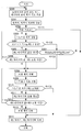
도 2는 본 실시 형태의 프라이머리 풀리압의 산출 방법을 설명하는 흐름도이다.
도 3은 본 실시 형태의 프라이머리 풀리압의 지시압을 보정하는 보정 제어를 설명하는 흐름도이다.1 is a schematic configuration diagram of a V-belt type continuously variable transmission according to the present embodiment.
Fig. 2 is a flowchart for explaining the primary pulley pressure calculating method of the embodiment.
3 is a flow chart for explaining correction control for correcting the indicated pressure of the primary pulley pressure according to the embodiment.
본 발명의 실시 형태의 구성에 대하여 도 1을 사용하여 설명한다. 도 1은 본 실시 형태의 V벨트식 무단 변속기의 개략 구성도이다. 또한, 이하의 설명에 있어서, 「변속비」는 V벨트식 무단 변속기(이하, 무단 변속기라 함)의 입력 회전 속도를 출력 회전 속도로 나누어 얻어지는 값이다. 그 때문에, 변속비가 작을수록 무단 변속기는 High측으로 되어 있다.The configuration of an embodiment of the present invention will be described with reference to Fig. 1 is a schematic configuration diagram of a V-belt type continuously variable transmission according to the present embodiment. In the following description, the " speed ratio " is a value obtained by dividing the input rotational speed of the V-belt type continuously variable transmission (hereinafter referred to as the continuously variable transmission) by the output rotational speed. Therefore, the lower the speed change ratio, the higher the continuously variable transmission is.
무단 변속기(1)는 프라이머리 풀리(2)와, 세컨더리 풀리(3)와, 벨트(4)와, 유압 컨트롤 유닛(5)과, 컨트롤 유닛(6)을 구비한다.The continuously variable transmission 1 is provided with a
프라이머리 풀리(2)는, 입력축(15)과 일체로 되어 회전하는 고정 원추판(2a)과, 고정 원추판(2a)에 대향 배치되어 V자 형상의 풀리 홈을 형성하는 가동 원추판(2b)을 구비한다. 가동 원추판(2b)은, 프라이머리 풀리 실린더실(2c)에 프라이머리 풀리압이 급배됨으로써 축방향을 따라서 변위한다. 프라이머리 풀리(2)는, 토크 컨버터(도시 생략), 입력축(15) 등을 통하여 엔진(도시 생략) 등의 구동원에서 발생한 회전이 전달된다.The
세컨더리 풀리(3)는, 출력축(16)과 일체로 되어 회전하는 고정 원추판(3a)과, 고정 원추판(3a)에 대향 배치되어 V자 형상의 풀리 홈을 형성하는 가동 원추판(3b)을 구비한다. 가동 원추판(3b)은, 세컨더리 풀리 실린더실(3c)에 세컨더리 풀리압이 급배됨으로써 축방향을 따라서 변위한다. 세컨더리 풀리(3)는, 벨트(4)에 의해 프라이머리 풀리(2)로부터 회전이 전달된다. 세컨더리 풀리(3)에 전달된 회전은, 출력축(16), 디퍼런셜(도시 생략) 등을 통하여 구동륜(도시 생략)에 전달된다.The
벨트(4)는, 프라이머리 풀리(2)와 세컨더리 풀리(3) 사이에 권회되어, 프라이머리 풀리(2)의 회전을 세컨더리 풀리(3)에 전달한다.The
유압 컨트롤 유닛(5)은, 레귤레이터 밸브(7)와, 감압 밸브(8)를 구비한다.The
레귤레이터 밸브(7)는, 유압 펌프(9)로부터 토출된 유압을 조절하는 솔레노이드(10)를 구비한다. 레귤레이터 밸브(7)는, 컨트롤 유닛(6)으로부터의 지령(예를 들면, 듀티 신호 등)에 따라서 솔레노이드(10)를 동작시킴으로써, 유압 펌프(9)로부터 토출된 오일의 압력을 운전 상태에 따른 소정의 라인압으로 조절한다. 라인압은 세컨더리 풀리압으로서 세컨더리 풀리 실린더실(3c)에 급배된다.The regulator valve (7) has a solenoid (10) for regulating the hydraulic pressure discharged from the hydraulic pump (9). The
감압 밸브(8)는 라인압을 조절하는 솔레노이드(11)를 구비한다. 감압 밸브(8)는 컨트롤 유닛(6)으로부터의 지령(예를 들면, 듀티 신호 등)에 따라서 솔레노이드(11)를 동작시킴으로써, 라인압을 운전 상태에 따른 소정의 프라이머리 풀리압으로 조절한다. 프라이머리 풀리압은, 프라이머리 풀리 실린더실(2c)에 급배된다. 프라이머리 풀리 실린더실(2c)로부터 유압을 배출하는 경우에는, 프라이머리 풀리 실린더실(2c)과 감압 밸브(8)의 드레인(8a)이 연통하여, 배출로가 형성된다. 감압 밸브(8)와 프라이머리 풀리 실린더실(2c) 사이에는 오리피스(12)가 형성되어 있고, 오리피스(12)에서는 오일의 흐름에 대하여 유로 저항이 발생한다.The pressure reducing valve (8) has a solenoid (11) for adjusting the line pressure. The
컨트롤 유닛(6)은, 프라이머리 풀리 회전 속도 센서(20)로부터의 신호, 세컨더리 풀리 회전 속도 센서(21)로부터의 신호 등에 기초하여 솔레노이드(10, 11)를 제어하는 신호를 출력하여, 프라이머리 풀리압 및 세컨더리 풀리압을 제어한다. 이에 의해, 무단 변속기(1)의 실제 변속비가 목표 변속비에 추종하여 변경된다.The
다음에 프라이머리 풀리압의 산출 방법에 대하여 도 2의 흐름도를 사용하여 설명한다.Next, a calculation method of the primary pulley pressure will be described using the flowchart of Fig.
스텝 S100에서는, 컨트롤 유닛(6)은 액셀러레이터 페달 개방도, 엔진 토크(입력 토크) 등의 신호에 기초하여 목표 변속비를 산출한다.In step S100, the
스텝 S101에서는, 컨트롤 유닛(6)은, 프라이머리 풀리 회전 속도 센서(20)로부터의 신호에 기초하여 프라이머리 풀리 회전 속도 Np를 산출하고, 세컨더리 풀리 회전 속도 센서(21)로부터의 신호에 기초하여 세컨더리 풀리 회전 속도 Ns를 산출한다.In step S101, the
스텝 S102에서는, 컨트롤 유닛(6)은, 프라이머리 풀리 회전 속도 Np 및 세컨더리 풀리 회전 속도 Ns에 기초하여 변속비 ip 및 변속비 변화량 ip'를 산출한다. 변속비 변화량 ip'는 단위 시간당의 변속비의 변화량이며, 전회의 제어에 있어서의 스텝 S101에서 산출된 프라이머리 풀리 회전 속도 Np 및 세컨더리 풀리 회전 속도 Ns 등을 사용하여 산출된다.In step S102, the
스텝 S103에서는, 컨트롤 유닛(6)은 수학식 1에 기초하여 프라이머리 풀리(2)의 가동 원추판(2b)의 스트로크 속도 xp를 산출한다.In step S103, the

f는 프라이머리 풀리(2)의 시브각이다. Rp는 프라이머리 풀리(2)와 벨트(4)의 접촉 반경이며, 수학식 2에 기초하여 산출된다. C는 프라이머리 풀리(2)와 세컨더리 풀리(3)의 축간 거리이다.and f is the sheave angle of the

a, b, c는 수학식 3에 나타내는 값이다.a, b, and c are values shown in Equation (3).

L은 벨트(4)의 길이이다.L is the length of the
스텝 S104에서는, 컨트롤 유닛(6)은, 수학식 4에 나타내는 프라이머리 풀리 실린더실(2c)에 있어서의 오일의 유량 변화량 Qp와, 수학식 5에 나타내는 감압 밸브(8)의 드레인(8a)으로부터 배출되는 오일의 유량 Qv로부터, 수학식 6에 나타내는 프라이머리 풀리 실린더실(2c)로부터 오일을 배출하는 경우의 오리피스(12) 전후의 압력차(P1-P2)를 산출한다. 유량 변화량 Qp와 유량 Qv는 동등하다.In step S104, the
![]()
![]()
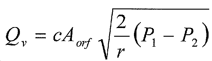

Ap는 프라이머리 풀리(2)의 가동 원추판(2b)의 수압 면적이다. c는 유량 계수이다. Aorf는 오리피스(12)의 교축 면적이다. r은 오일의 밀도이다. P1은 오리피스(12)보다도 프라이머리 풀리(2)측의 압력이다. P2는 오리피스(12)보다도 드레인(8a)측의 압력이며, 프라이머리 풀리압의 지시압이다.A p is the hydraulic pressure area of the movable
오리피스(12) 전후의 압력차(P1-P2)는, 오리피스(12)의 유로 저항, 프라이머리 풀리(2)의 가동 원추판(2b)의 스트로크 속도 xp에 따른 프라이머리 풀리 실린더실(2c)의 내압의 증가량으로 된다. 프라이머리 풀리 실린더실(2c)의 내압의 증가량은, 스트로크 속도 xp가 커짐에 따라서 커진다. 따라서, 스텝 S105에 있어서, 컨트롤 유닛(6)은, 액셀러레이터 페달 개방도, 엔진 토크 등에 기초하여 산출한 프라이머리 풀리압(제1 풀리압)으로부터 프라이머리 풀리 실린더실(2c)의 내압의 증가량을 감산하여, 프라이머리 풀리압의 지시압을 산출한다.The pressure difference (P 1 -P 2 ) before and after the
산출된 프라이머리 풀리압의 지시압에 따라서 감압 밸브(8)가 제어됨으로써, 빠르게 프라이머리 풀리압이 저하되어, 목표 변속비에 대한 실제 변속비의 추종성을 양호하게 할 수 있다.By controlling the
다음에 도 2를 사용하여 설명한 프라이머리 풀리압의 지시압을 보정하는 보정 제어에 대하여 도 3의 흐름도를 사용하여 설명한다.Next, correction control for correcting the indicated pressure of the primary pulley pressure described with reference to Fig. 2 will be described using the flowchart of Fig.
스텝 S200에서는, 컨트롤 유닛(6)은 프라이머리 풀리 회전 속도 센서(20)로부터의 신호에 기초하여 프라이머리 풀리 회전 속도 Np를 산출하고, 세컨더리 풀리 회전 속도 센서(21)로부터의 신호에 기초하여 세컨더리 풀리 회전 속도 Ns를 산출한다.In step S200, the
스텝 S201에서는, 컨트롤 유닛(6)은, 프라이머리 풀리 회전 속도 Np와 세컨더리 풀리 회전 속도 Ns에 기초하여 변속비 ip, 변속비 변화량 ip'를 산출한다. 산출 방법은 스텝 S101과 동일하다.In step S201, the
스텝 S202에서는, 컨트롤 유닛(6)은, 다운 시프트 중인지 여부를 판정한다. 컨트롤 유닛(6)은, 다운 시프트 중인 경우에는 스텝 S203으로 진행하고, 다운 시프트 중이 아닌 경우에는 스텝 S214로 진행한다.In step S202, the
스텝 S203에서는, 컨트롤 유닛(6)은 수학식 1에 기초하여 프라이머리 풀리(2)의 가동 원추판(2b)의 스트로크 속도 xp를 산출한다.In step S203, the
스텝 S204에서는, 컨트롤 유닛(6)은, 산출한 스트로크 속도 xp가 제1 소정값 이상인지 여부를 판정한다. 컨트롤 유닛(6)은, 스트로크 속도 xp가 제1 소정값 이상인 경우에는 스텝 S205로 진행하고, 스트로크 속도 xp가 제1 소정값보다도 작은 경우에는 스텝 S207로 진행한다. 제1 소정값은 미리 설정된 값이며, 벨트(4)와 프라이머리 풀리(2) 사이에서 벨트 미끄럼이 발생하고 있지 않은 경우에 취할 수 있는 값이며, 예를 들면 벨트 미끄럼이 발생하지 않는 한계치이다.In step S204, the
프라이머리 풀리(2)와 벨트(4) 사이에서 벨트 미끄럼이 발생하면, 프라이머리 풀리 회전 속도 Np가 커져, 변속비 ip가 커진다. 수학식 1에 기초하여 스트로크 속도 xp를 산출하고 있으므로, 벨트 미끄럼이 발생하면 프라이머리 풀리(2)의 가동 원추판(2b)이 이동하고 있지 않음에도 불구하고 스트로크 속도 xp가 커지거나, 또는 프라이머리 풀리(2)의 가동 원추판(2b)의 실제의 이동량에 대하여 스트로크 속도 xp가 커진다.When the belt slip occurs between the
스텝 S205에서는, 컨트롤 유닛(6)은 제1 타이머의 값을 갱신한다. 컨트롤 유닛(6)은 현재의 제1 타이머의 값에 1을 가산한다. 제1 타이머의 값은 초기값으로서 제로로 설정되어 있고, 리셋되면 제로로 복귀된다.In step S205, the
스텝 S206에서는, 컨트롤 유닛(6)은 제1 타이머의 값과 제1 소정 시간을 비교한다. 컨트롤 유닛(6)은, 제1 타이머의 값이 제1 소정 시간으로 되는, 즉 스트로크 속도 xp가 제1 소정값 이상으로 되는 상태가 제1 소정 시간 계속되었는지 여부를 판정한다. 컨트롤 유닛(6)은, 제1 타이머의 값이 제1 소정 시간으로 된 경우에는 스텝 S208로 진행하고, 제1 타이머의 값이 제1 소정 시간으로 되지 않은 경우에는 스텝 S200으로 되돌아가 상기 제어를 반복한다.In step S206, the
스텝 S207에서는, 컨트롤 유닛(6)은, 변속비 ip가 최High 이상이고, 또한 최Low 이하인지 여부를 판정한다. 컨트롤 유닛(6)은, 변속비 ip가 최High 이상이고, 또한 최Low 이하인 경우에는 변속비 ip가 통상 취할 수 있는 범위, 즉 벨트 미끄럼이 발생하지 않았다고 판단하고, 스텝 214로 진행하고, 변속비 ip가 최High보다도 작거나, 또는 최Low보다도 큰 경우에는 변속비 ip가 통상 취할 수 있는 범위가 아니며, 벨트 미끄럼이 발생하였다고 판정하고, 스텝 S208로 진행한다.In step S207, the
벨트 미끄럼이 발생하면, 컨트롤 유닛(6)은, 수학식 6에 나타내는 오리피스(12) 전후의 압력차(P1-P2)가 커졌다고 오검지할 우려가 있다. 오검지되면 프라이머리 풀리압의 지시압이 낮아진다. 이에 의해, 프라이머리 풀리(2)에 의한 벨트(4)의 끼움 지지력이 작아져, 한층 더한 벨트 미끄럼이 발생한다. 따라서, 스텝 S208에서는, 컨트롤 유닛(6)은 프라이머리 풀리압을 보정하는 보정 제어를 실행한다. 구체적으로는, 프라이머리 풀리압의 지시압에 프라이머리 풀리 실린더실(2c)의 내압의 증가량을 가산한다.When the belt slip occurs, the
스텝 S209에서는, 컨트롤 유닛(6)은 수학식 1에 기초하여 프라이머리 풀리(2)의 가동 원추판(2b)의 스트로크 속도 xp를 산출한다.In step S209, the
스텝 S210에서는, 컨트롤 유닛(6)은, 스텝 S209에 의해 산출한 스트로크 속도 xp가 제2 소정값보다도 작은지 여부를 판정한다. 컨트롤 유닛(6)은, 스트로크 속도 xp가 제2 소정값보다도 작은 경우에는 스텝 S211로 진행하고, 스트로크 속도 xp가 제2 소정값 이상인 경우에는 스텝 S214로 진행한다. 제2 소정값은, 벨트 미끄럼이 수렴된다고 판정 가능한 값이며, 제1 소정값보다도 작고, 미리 설정되어 있다.In step S210, the
스텝 S211에서는, 컨트롤 유닛(6)은 제2 타이머의 값을 갱신한다. 컨트롤 유닛(6)은, 현재의 제2 타이머의 값에 1을 가산한다. 제2 타이머의 값은 초기값으로서 제로로 설정되어 있고, 리셋되면 제로로 복귀된다.In step S211, the
스텝 S212에서는, 컨트롤 유닛(6)은 제2 타이머의 값과 제2 소정 시간을 비교한다. 컨트롤 유닛(6)은, 제2 타이머의 값이 제2 소정 시간으로 된 경우에는 스텝 S213으로 진행하고, 제2 타이머의 값이 제2 소정 시간으로 되지 않은 경우에는 스텝 S208로 되돌아가서 상기 제어를 반복한다. 제2 소정 시간은, 스트로크 속도 xp가 제2 소정값보다도 작은 상태가 계속됨으로써, 벨트 미끄럼이 수렴되었다고 판정하는 시간이며, 미리 설정되어 있다.In step S212, the
스텝 S213에서는, 컨트롤 유닛(6)은 보정 제어를 종료한다.In step S213, the
스텝 S214에서는, 컨트롤 유닛(6)은 제1 타이머 및 제2 타이머를 리셋한다.In step S214, the
본 발명의 실시 형태의 효과에 대하여 설명한다.Effects of the embodiment of the present invention will be described.
다운 시프트 중에 프라이머리 풀리(2)의 가동 원추판(2b)의 스트로크 속도 xp와, 오리피스(12)의 유로 저항에 기초하여, 프라이머리 풀리 실린더실(2c)의 내압의 증가량을 산출하고, 액셀러레이터 페달 개방도, 엔진 토크 등에 의해 산출되는 프라이머리 풀리압으로부터 증가량을 감산한 값을 프라이머리 풀리(2)의 지시압으로 한다. 이에 의해, 다운 시프트 중에 프라이머리 풀리 실린더실(2c)의 유압 상승을 억제할 수 있어, 목표 변속비에 대한 실제 변속비의 추종성을 양호하게 할 수 있어, 변속을 신속하게 실행할 수 있다.The increase amount of the internal pressure of the primary
벨트 미끄럼이 발생하면, 프라이머리 풀리압의 감소량이 커져, 프라이머리 풀리(2)에 의한 벨트(4)의 끼움 지지력이 저하되어, 한층 더한 벨트 미끄럼이 발생할 우려가 있다.If the belt slip occurs, the reduction amount of the primary pulley pressure is increased, and the fitting force of the
따라서, 벨트(4)와 프라이머리 풀리(2) 사이에서 벨트 미끄럼이 발생하는 경우에는, 프라이머리 풀리(2)의 지시압에 프라이머리 풀리 실린더실(2c)의 내압의 증가량을 가산하는 보정 제어를 실행한다. 이에 의해, 벨트 미끄럼이 발생한 경우라도, 프라이머리 풀리압의 지시압이 낮아지는 것을 억제하여, 한층 더한 벨트 미끄럼이 발생하는 것을 억제할 수 있다.Therefore, in the case where belt slippage occurs between the
변속비가 통상 취할 수 있는 변속비가 아닌 경우, 즉 변속비가 최High보다도 작거나, 또는 변속비가 최Low보다도 큰 경우에 벨트 미끄럼이 발생한다고 판정하고, 프라이머리 풀리압의 보정 제어를 실행한다. 이에 의해, 한층 더한 벨트 미끄럼의 발생을 억제할 수 있다.It is determined that belt slippage occurs and the correction control of the primary pulley pressure is executed when the speed ratio is not a normal speed ratio, that is, the speed ratio is smaller than the highest speed or the speed ratio is greater than the lowest speed. Thereby, the occurrence of further belt slippage can be suppressed.
벨트 미끄럼이 발생하지 않은 경우에 취할 수 있는 제1 소정값보다도 스트로크 속도 xp가 큰 경우에 벨트 미끄럼이 발생한다고 판정하고, 보정 제어를 실행한다. 이에 의해, 한층 더한 벨트 미끄럼의 발생을 억제할 수 있다.It is determined that belt slippage occurs and the correction control is executed when the stroke speed x p is larger than the first predetermined value that can be taken when the belt slip does not occur. Thereby, the occurrence of further belt slippage can be suppressed.
벨트 미끄럼이 수렴된 경우에는 보정 제어를 종료함으로써, 실제 변속비를 목표 변속비까지 빠르게 변경하여, 변속을 신속하게 실행할 수 있다.In the case where the belt slip converges, the actual speed change ratio can be quickly changed to the target speed change ratio by completing the correction control, and the shifting can be performed quickly.
이상, 본 발명의 실시 형태에 대하여 설명하였지만, 상기 실시 형태는 본 발명의 적용예의 일부를 나타낸 것에 지나지 않고, 본 발명의 기술적 범위를 상기 실시 형태의 구체적 구성에 한정한다는 취지는 아니다.Although the embodiments of the present invention have been described above, the above embodiments are only illustrative of some of the application examples of the present invention, and the technical scope of the present invention is not limited to the specific configurations of the above embodiments.
상기 실시 형태에서는, 다운 시프트 중에 있어서의 프라이머리 풀리압의 산출 방법에 대하여 설명하였지만, 이것에 한정되는 것은 아니고, 유압을 배출하여 풀리가 이동하는 경우에 사용할 수 있다.In the above-described embodiment, the calculation method of the primary pulley pressure during downshifting has been described. However, the present invention is not limited to this, and the pulley may be used when the hydraulic pressure is discharged to move the pulley.
동력 전달 부재로서 벨트(4)를 사용한 V벨트4식 무단 변속기에 대하여 설명하였지만, 동력 전달 부재는 벨트(4)가 아니라, 체인 등이어도 된다.Although the V-belt four-speed continuously variable transmission using the
배출로의 유로 저항은, 오리피스(12)에 의한 유로 저항 외에 배출로와 오일의 마찰 저항 등을 고려해도 된다.The flow path resistance of the discharge path may be considered in addition to the flow path resistance by the
본원은 2011년 12월 13일에 일본 특허청에 출원된 일본 특허 출원 제2011-271982에 기초하는 우선권을 주장하고, 이 출원의 모든 내용은 참조에 의해 본 명세서에 포함된다.The present application claims priority based on Japanese Patent Application No. 2011-271982 filed on December 13, 2011, the entirety of which is incorporated herein by reference.
Claims (6)
제2 고정 풀리와, 상기 제2 고정 풀리와 동축상에 배치되며, 축방향을 따라서 이동함으로써 상기 제2 고정 풀리와의 사이에 형성되는 홈폭을 변경하는 제2 가동 풀리를 갖는 제2 풀리와,
상기 제1 풀리와 상기 제2 풀리 사이에 권회된 동력 전달 부재를 구비하는 무단 변속기이며,
상기 제1 풀리의 지시압을 산출하는 지시압 산출 수단과,
상기 제1 가동 풀리의 축방향을 따른 이동 속도인 스트로크 속도를 산출하는 스트로크 속도 산출 수단과,
상기 제1 풀리 유실로부터 상기 오일을 배출하는 경우에, 배출로의 유로 저항에 의해 증가하는 상기 제1 풀리 유실의 유압 증가량을, 상기 유로 저항과 상기 스트로크 속도에 기초하여 산출하는 유압 산출 수단을 구비하고,
상기 지시압 산출 수단은, 상기 제1 풀리 유실로부터 상기 오일을 배출하는 경우에, 목표 변속비 및 입력 토크에 기초하여 산출한 제1 풀리압으로부터 상기 유압 증가량을 감산하여 상기 제1 풀리의 지시압을 산출하는, 무단 변속기.A first fixed pulley and a second fixed pulley which are disposed coaxially with the first fixed pulley and change a groove width formed between the first fixed pulley and the first fixed pulley by moving along the axial direction by a diaphragm of oil to the first pulley chamber A first pulley having a first movable pulley,
A second pulley having a second fixed pulley and a second movable pulley coaxially disposed with the second fixed pulley and changing a groove width formed between the first fixed pulley and the second fixed pulley by moving along the axial direction;
And a power transmitting member wound between the first pulley and the second pulley,
An indicating pressure calculating means for calculating an indicating pressure of the first pulley,
Stroke speed calculating means for calculating a stroke speed which is a moving speed along the axial direction of the first movable pulley;
And hydraulic pressure calculating means for calculating an oil pressure increase amount of the first pulley oil chamber which is increased by the flow path resistance of the discharge path when the oil is discharged from the first pulley oil chamber based on the flow path resistance and the stroke speed and,
Wherein the indicated pressure calculating means subtracts the hydraulic pressure increase amount from the first pulley pressure calculated based on the target transmission ratio and the input torque when the oil is discharged from the first pulley chamber, Continuously variable transmission.
상기 제1 풀리의 제1 회전 속도를 검출하는 제1 회전 속도 검출 수단과,
상기 제2 풀리의 제2 회전 속도를 검출하는 제2 회전 속도 검출 수단과,
상기 제1 회전 속도와 상기 제2 회전 속도에 기초하여 변속비를 산출하는 변속비 산출 수단과,
상기 동력 전달 부재와 상기 제1 풀리 사이에서 상기 동력 전달 부재의 미끄럼이 발생하는지 여부를 판정하는 미끄럼 판정 수단과,
상기 동력 전달 부재의 미끄럼이 발생하는 경우에, 상기 제1 풀리의 지시압에 상기 유압 증가량을 가산하는 보정 제어를 실행하는 보정 수단을 구비하고,
상기 스트로크 속도 산출 수단은, 상기 변속비에 기초하여 상기 스트로크 속도를 산출하는, 무단 변속기.The method according to claim 1,
First rotational speed detecting means for detecting a first rotational speed of the first pulley,
Second rotational speed detecting means for detecting a second rotational speed of the second pulley,
Speed ratio calculating means for calculating a speed ratio based on the first rotation speed and the second rotation speed,
Slip determination means for determining whether or not a slip of the power transmitting member occurs between the power transmitting member and the first pulley,
And correction means for executing correction control for adding the hydraulic pressure increase amount to the indicated pressure of the first pulley when slippage of the power transmitting member occurs,
And the stroke speed calculating means calculates the stroke speed based on the speed ratio.
상기 보정 수단은, 상기 변속비가 최High보다 작은 경우, 또는 상기 변속비가 최Low보다 큰 경우에 상기 보정 제어를 실행하는, 무단 변속기.3. The method of claim 2,
Wherein the correction means executes the correction control when the speed ratio is lower than the highest speed or when the speed ratio is higher than the lowest speed.
상기 보정 수단은, 상기 스트로크 속도가 상기 동력 전달 부재의 미끄럼 불발생 시의 속도보다도 큰 경우에 상기 보정 제어를 실행하는, 무단 변속기.The method according to claim 2 or 3,
Wherein said correction means executes said correction control when said stroke speed is greater than a speed at which said power transmitting member does not slip.
상기 보정 수단은, 상기 보정 제어를 실행한 후에, 상기 동력 전달 부재의 미끄럼이 수렴되었다고 판정된 경우에는, 상기 보정 제어를 종료하는, 무단 변속기.5. The method according to any one of claims 2 to 4,
Wherein said correction means ends the correction control when it is determined that the slip of the power transmitting member has converged after executing the correction control.
제2 고정 풀리와, 상기 제2 고정 풀리와 동축상에 배치되며, 축방향을 따라서 이동함으로써 상기 제2 고정 풀리와의 사이에 형성되는 홈폭을 변경하는 제2 가동 풀리를 갖는 제2 풀리와,
상기 제1 풀리와 상기 제2 풀리 사이에 권회된 동력 전달 부재를 구비하는 무단 변속기를 제어하는 무단 변속기의 제어 방법이며,
상기 제1 가동 풀리의 축방향을 따른 이동 속도인 스트로크 속도를 산출하고,
상기 제1 풀리 유실로부터 상기 오일을 배출하는 경우에, 배출로의 유로 저항에 의해 증가하는 상기 제1 풀리 유실의 유압 증가량을, 상기 유로 저항과 상기 스트로크 속도에 기초하여 산출하고,
상기 제1 풀리 유실로부터 상기 오일을 배출하는 경우에, 목표 변속비 및 구동원으로부터의 입력 토크에 기초하여 산출한 제1 풀리압으로부터 상기 유압 증가량을 감산하여 상기 제1 풀리의 지시압을 산출하는, 무단 변속기의 제어 방법.A first fixed pulley and a second fixed pulley which are disposed coaxially with the first fixed pulley and change a groove width formed between the first fixed pulley and the first fixed pulley by moving along the axial direction by a diaphragm of oil to the first pulley chamber A first pulley having a first movable pulley,
A second pulley having a second fixed pulley and a second movable pulley coaxially disposed with the second fixed pulley and changing a groove width formed between the first fixed pulley and the second fixed pulley by moving along the axial direction;
And a power transmitting member wound between the first pulley and the second pulley. The control method of the continuously variable transmission includes:
A stroke speed which is a moving speed along the axial direction of the first movable pulley is calculated,
An oil pressure increase amount of the first pulley oil chamber which is increased by the oil passage resistance of the discharge passage when the oil is discharged from the first oil chamber is calculated on the basis of the oil passage resistance and the stroke speed,
And a control unit for calculating the indicated pressure of the first pulley by subtracting the hydraulic pressure increase amount from the first pulley pressure calculated based on the target transmission ratio and the input torque from the drive source when the oil is discharged from the first pulley chamber, A method of controlling a transmission.
Applications Claiming Priority (3)
| Application Number | Priority Date | Filing Date | Title |
|---|---|---|---|
| JP2011271982 | 2011-12-13 | ||
| JPJP-P-2011-271982 | 2011-12-13 | ||
| PCT/JP2012/079262 WO2013088881A1 (en) | 2011-12-13 | 2012-11-12 | Continuously variable transmission and method for controlling continuously variable transmission |
Publications (2)
| Publication Number | Publication Date |
|---|---|
| KR20140101364A true KR20140101364A (en) | 2014-08-19 |
| KR101558830B1 KR101558830B1 (en) | 2015-10-07 |
Family
ID=48612336
Family Applications (1)
| Application Number | Title | Priority Date | Filing Date |
|---|---|---|---|
| KR1020147015983A KR101558830B1 (en) | 2011-12-13 | 2012-11-12 | Continuously variable transmission and method for controlling continuously variable transmission |
Country Status (6)
| Country | Link |
|---|---|
| US (1) | US9062742B2 (en) |
| EP (1) | EP2792912A4 (en) |
| JP (1) | JP5749815B2 (en) |
| KR (1) | KR101558830B1 (en) |
| CN (1) | CN104024701B (en) |
| WO (1) | WO2013088881A1 (en) |
Families Citing this family (6)
| Publication number | Priority date | Publication date | Assignee | Title |
|---|---|---|---|---|
| NL1041280B1 (en) * | 2015-04-21 | 2017-01-26 | Gear Chain Ind Bv | A control system for a continuously variable transmission. |
| JP6508429B2 (en) * | 2016-09-16 | 2019-05-08 | 日産自動車株式会社 | Transmission control method for continuously variable transmission and transmission control apparatus |
| CN112639330A (en) * | 2018-10-22 | 2021-04-09 | 加特可株式会社 | Continuously variable transmission for vehicle |
| US20210199187A1 (en) * | 2018-10-22 | 2021-07-01 | Jatco Ltd | Continuously variable transmission |
| CN112639329A (en) * | 2018-10-22 | 2021-04-09 | 加特可株式会社 | Continuously variable transmission |
| CN110715052A (en) * | 2019-10-28 | 2020-01-21 | 周翔 | Transmission speed change control system |
Family Cites Families (17)
| Publication number | Priority date | Publication date | Assignee | Title |
|---|---|---|---|---|
| JPS61105352A (en) * | 1984-10-30 | 1986-05-23 | Nissan Motor Co Ltd | Shift controller for stepless transmission |
| JPS6320560U (en) * | 1986-07-25 | 1988-02-10 | ||
| JPS63275847A (en) * | 1987-04-30 | 1988-11-14 | Fuji Heavy Ind Ltd | Oil pressure control device of continuous variable transmission |
| JPH0212562U (en) * | 1988-07-08 | 1990-01-25 | ||
| JP3358381B2 (en) * | 1995-04-24 | 2002-12-16 | 日産自動車株式会社 | Control device for continuously variable automatic transmission |
| JP3430934B2 (en) * | 1998-09-08 | 2003-07-28 | 日産自動車株式会社 | Transmission control device for V-belt type continuously variable transmission |
| JP4044220B2 (en) * | 1998-09-21 | 2008-02-06 | 富士重工業株式会社 | Control device for continuously variable transmission |
| JP2004069026A (en) * | 2002-08-09 | 2004-03-04 | Suzuki Motor Corp | Gear ratio control device for continuously variable transmission |
| JP3944042B2 (en) * | 2002-09-19 | 2007-07-11 | ジヤトコ株式会社 | Hydraulic pressure reduction rate limiting device for V-belt type continuously variable transmission |
| JP4145856B2 (en) * | 2004-10-05 | 2008-09-03 | ジヤトコ株式会社 | Line pressure control device for belt type continuously variable transmission |
| JP4602207B2 (en) | 2005-09-07 | 2010-12-22 | ジヤトコ株式会社 | Hydraulic control device for belt type continuously variable transmission for vehicle |
| JP4731505B2 (en) * | 2006-03-17 | 2011-07-27 | ジヤトコ株式会社 | Hydraulic control device for belt type continuously variable transmission |
| JP4238895B2 (en) * | 2006-08-11 | 2009-03-18 | トヨタ自動車株式会社 | Shift control device for continuously variable transmission for vehicle |
| JP2009185885A (en) * | 2008-02-06 | 2009-08-20 | Fuji Heavy Ind Ltd | Hydraulic control device for continuously variable transmission |
| JP5027179B2 (en) * | 2009-03-27 | 2012-09-19 | ジヤトコ株式会社 | Continuously variable transmission and control method thereof |
| JP5377072B2 (en) * | 2009-05-19 | 2013-12-25 | 富士重工業株式会社 | Control device for continuously variable transmission |
| JP4847567B2 (en) * | 2009-08-26 | 2011-12-28 | ジヤトコ株式会社 | Continuously variable transmission and control method thereof |
-
2012
- 2012-11-12 CN CN201280061639.XA patent/CN104024701B/en active Active
- 2012-11-12 EP EP12857363.1A patent/EP2792912A4/en not_active Withdrawn
- 2012-11-12 KR KR1020147015983A patent/KR101558830B1/en active IP Right Grant
- 2012-11-12 JP JP2013549168A patent/JP5749815B2/en active Active
- 2012-11-12 WO PCT/JP2012/079262 patent/WO2013088881A1/en active Application Filing
- 2012-11-12 US US14/364,566 patent/US9062742B2/en active Active
Also Published As
| Publication number | Publication date |
|---|---|
| WO2013088881A1 (en) | 2013-06-20 |
| CN104024701B (en) | 2016-03-02 |
| KR101558830B1 (en) | 2015-10-07 |
| US20140342860A1 (en) | 2014-11-20 |
| CN104024701A (en) | 2014-09-03 |
| EP2792912A4 (en) | 2017-03-08 |
| JP5749815B2 (en) | 2015-07-15 |
| JPWO2013088881A1 (en) | 2015-04-27 |
| US9062742B2 (en) | 2015-06-23 |
| EP2792912A1 (en) | 2014-10-22 |
Similar Documents
| Publication | Publication Date | Title |
|---|---|---|
| KR101558830B1 (en) | Continuously variable transmission and method for controlling continuously variable transmission | |
| JP4939915B2 (en) | Control device for continuously variable transmission | |
| KR100581252B1 (en) | A line pressure variable control method and a system thereof for an automatic transmission | |
| US8831846B2 (en) | Controller of continuously variable transmission | |
| US9080671B2 (en) | Continuously-variable transmission and continuously-variable transmission control method | |
| JP2010169128A (en) | Control device for driving device of vehicle | |
| JP4668391B2 (en) | Hydraulic control device for automatic transmission | |
| JP3873756B2 (en) | Control device for continuously variable transmission | |
| US10815846B2 (en) | Continuously variable transmission and method for controlling continuously variable transmission | |
| JP2008075736A (en) | Shift control device for vehicular continuously variable transmission | |
| JP2010242935A (en) | Vehicle control device | |
| CN109964059B (en) | Continuously variable transmission | |
| JPS62122837A (en) | Controller for continuously variable transmission | |
| US10982764B2 (en) | Control method and control device for continuously variable transmission | |
| JP6913249B2 (en) | Control device for continuously variable transmission | |
| JP7393168B2 (en) | Control device for continuously variable belt transmission and belt slip determination method for continuously variable belt transmission | |
| US11460103B2 (en) | Lock-up disengagement control device for automatic transmission | |
| JP7041563B2 (en) | Hydraulic control device | |
| US10781919B2 (en) | Method for controlling continuously variable transmission and continuously variable transmission system | |
| JP2008057587A (en) | Speed change controller of belt type continuously variable transmission | |
| JP5817583B2 (en) | Control device for continuously variable transmission | |
| JP2020060259A (en) | Control device of power transmission mechanism | |
| JP2020026811A (en) | Shift control device for continuously variable transmission | |
| JP2008202681A (en) | Control system of belt-type continuously variable transmission | |
| JP2010169127A (en) | Control device for continuously variable transmission |
Legal Events
| Date | Code | Title | Description |
|---|---|---|---|
| A201 | Request for examination | ||
| E701 | Decision to grant or registration of patent right | ||
| GRNT | Written decision to grant | ||
| FPAY | Annual fee payment |
Payment date: 20180903 Year of fee payment: 4 |
|
| FPAY | Annual fee payment |
Payment date: 20190829 Year of fee payment: 5 |