KR20140097321A - Method and device for setting uplink transmission power in wireless communication system - Google Patents
Method and device for setting uplink transmission power in wireless communication system Download PDFInfo
- Publication number
- KR20140097321A KR20140097321A KR1020147015446A KR20147015446A KR20140097321A KR 20140097321 A KR20140097321 A KR 20140097321A KR 1020147015446 A KR1020147015446 A KR 1020147015446A KR 20147015446 A KR20147015446 A KR 20147015446A KR 20140097321 A KR20140097321 A KR 20140097321A
- Authority
- KR
- South Korea
- Prior art keywords
- random access
- base station
- value
- scell
- uplink transmission
- Prior art date
Links
Images


Classifications
-
- H—ELECTRICITY
- H04—ELECTRIC COMMUNICATION TECHNIQUE
- H04W—WIRELESS COMMUNICATION NETWORKS
- H04W52/00—Power management, e.g. TPC [Transmission Power Control], power saving or power classes
- H04W52/04—TPC
- H04W52/30—TPC using constraints in the total amount of available transmission power
- H04W52/32—TPC of broadcast or control channels
- H04W52/325—Power control of control or pilot channels
-
- H—ELECTRICITY
- H04—ELECTRIC COMMUNICATION TECHNIQUE
- H04L—TRANSMISSION OF DIGITAL INFORMATION, e.g. TELEGRAPHIC COMMUNICATION
- H04L5/00—Arrangements affording multiple use of the transmission path
- H04L5/003—Arrangements for allocating sub-channels of the transmission path
- H04L5/0032—Distributed allocation, i.e. involving a plurality of allocating devices, each making partial allocation
-
- H—ELECTRICITY
- H04—ELECTRIC COMMUNICATION TECHNIQUE
- H04J—MULTIPLEX COMMUNICATION
- H04J11/00—Orthogonal multiplex systems, e.g. using WALSH codes
- H04J11/0023—Interference mitigation or co-ordination
- H04J11/005—Interference mitigation or co-ordination of intercell interference
- H04J11/0053—Interference mitigation or co-ordination of intercell interference using co-ordinated multipoint transmission/reception
-
- H—ELECTRICITY
- H04—ELECTRIC COMMUNICATION TECHNIQUE
- H04W—WIRELESS COMMUNICATION NETWORKS
- H04W52/00—Power management, e.g. TPC [Transmission Power Control], power saving or power classes
- H04W52/04—TPC
- H04W52/06—TPC algorithms
- H04W52/14—Separate analysis of uplink or downlink
- H04W52/146—Uplink power control
-
- H—ELECTRICITY
- H04—ELECTRIC COMMUNICATION TECHNIQUE
- H04W—WIRELESS COMMUNICATION NETWORKS
- H04W52/00—Power management, e.g. TPC [Transmission Power Control], power saving or power classes
- H04W52/04—TPC
- H04W52/18—TPC being performed according to specific parameters
- H04W52/24—TPC being performed according to specific parameters using SIR [Signal to Interference Ratio] or other wireless path parameters
- H04W52/247—TPC being performed according to specific parameters using SIR [Signal to Interference Ratio] or other wireless path parameters where the output power of a terminal is based on a path parameter sent by another terminal
-
- H—ELECTRICITY
- H04—ELECTRIC COMMUNICATION TECHNIQUE
- H04W—WIRELESS COMMUNICATION NETWORKS
- H04W52/00—Power management, e.g. TPC [Transmission Power Control], power saving or power classes
- H04W52/04—TPC
- H04W52/30—TPC using constraints in the total amount of available transmission power
- H04W52/34—TPC management, i.e. sharing limited amount of power among users or channels or data types, e.g. cell loading
-
- H—ELECTRICITY
- H04—ELECTRIC COMMUNICATION TECHNIQUE
- H04W—WIRELESS COMMUNICATION NETWORKS
- H04W52/00—Power management, e.g. TPC [Transmission Power Control], power saving or power classes
- H04W52/04—TPC
- H04W52/38—TPC being performed in particular situations
- H04W52/40—TPC being performed in particular situations during macro-diversity or soft handoff
-
- H—ELECTRICITY
- H04—ELECTRIC COMMUNICATION TECHNIQUE
- H04W—WIRELESS COMMUNICATION NETWORKS
- H04W52/00—Power management, e.g. TPC [Transmission Power Control], power saving or power classes
- H04W52/04—TPC
- H04W52/38—TPC being performed in particular situations
- H04W52/50—TPC being performed in particular situations at the moment of starting communication in a multiple access environment
-
- H—ELECTRICITY
- H04—ELECTRIC COMMUNICATION TECHNIQUE
- H04L—TRANSMISSION OF DIGITAL INFORMATION, e.g. TELEGRAPHIC COMMUNICATION
- H04L5/00—Arrangements affording multiple use of the transmission path
- H04L5/0001—Arrangements for dividing the transmission path
- H04L5/0003—Two-dimensional division
- H04L5/0005—Time-frequency
- H04L5/0007—Time-frequency the frequencies being orthogonal, e.g. OFDM(A), DMT
- H04L5/001—Time-frequency the frequencies being orthogonal, e.g. OFDM(A), DMT the frequencies being arranged in component carriers
-
- H—ELECTRICITY
- H04—ELECTRIC COMMUNICATION TECHNIQUE
- H04W—WIRELESS COMMUNICATION NETWORKS
- H04W52/00—Power management, e.g. TPC [Transmission Power Control], power saving or power classes
- H04W52/04—TPC
- H04W52/18—TPC being performed according to specific parameters
- H04W52/24—TPC being performed according to specific parameters using SIR [Signal to Interference Ratio] or other wireless path parameters
- H04W52/248—TPC being performed according to specific parameters using SIR [Signal to Interference Ratio] or other wireless path parameters where transmission power control commands are generated based on a path parameter
Abstract
Description
본 발명은 무선통신에 관한 것으로, 보다 상세하게는 무선통신 시스템에서 상향링크 전송 전력을 설정하는 방법 및 이를 위한 장치에 관한 것이다.BACKGROUND OF THE
본 발명이 적용될 수 있는 이동통신 시스템의 일례로서 3GPP LTE(3rd Generation Partnership Project Long Term Evolution, 이하 'LTE'라 함), LTE-Advanced(이하, 'LTE-A'라 함) 통신 시스템에 대해 개략적으로 설명한다.As an example of a mobile communication system to which the present invention can be applied, an outline of a 3GPP LTE (Third Generation Partnership Project) Long Term Evolution (LTE) communication system and an LTE-Advanced (LTE- .
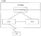
도 1은 이동통신 시스템의 일례로서 E-UMTS 망구조를 개략적으로 도시한 도면이다.1 is a diagram schematically illustrating an E-UMTS network structure as an example of a mobile communication system.
E-UMTS(Evolved Universal Mobile Telecommunications System) 시스템은 기존 UMTS(Universal Mobile Telecommunications System)에서 진화한 시스템으로서, 현재 3GPP에서 표준화 작업을 진행하고 있다. 일반적으로 E-UMTS는 LTE(Long Term Evolution) 시스템이라고 할 수도 있다. UMTS 및 E-UMTS의 기술 규격(technical specification)의 상세한 내용은 각각 "3rd Generation Partnership Project; Technical Specification Group Radio Access Network"의 Release 8과 Release 9을 참조할 수 있다.The Evolved Universal Mobile Telecommunications System (E-UMTS) system evolved from the existing UMTS (Universal Mobile Telecommunications System), and is currently being standardized in 3GPP. In general, E-UMTS may be referred to as an LTE (Long Term Evolution) system. For details of the technical specifications of UMTS and E-UMTS, refer to
도 1을 참조하면, E-UMTS는 단말(User Equipment, UE)과 기지국(eNode B, eNB), 네트워크(E-UTRAN)의 종단에 위치하여 외부 네트워크와 연결되는 접속 게이트웨이(Access Gateway, AG)를 포함한다. 기지국은 브로드캐스트 서비스, 멀티캐스트 서비스 및/또는 유니캐스트 서비스를 위해 다중 데이터 스트림을 동시에 전송할 수 있다.1, an E-UMTS includes an access gateway (AG) located at the end of a user equipment (UE), a base station (eNode B, eNB) and a network (E-UTRAN) . The base station may simultaneously transmit multiple data streams for broadcast services, multicast services, and / or unicast services.
한 기지국에는 하나 이상의 셀이 존재한다. 셀은 1.25, 2.5, 5, 10, 15, 20MHz 등의 대역폭 중 하나로 설정돼 여러 단말에게 하향 또는 상향 전송 서비스를 제공한다. 서로 다른 셀은 서로 다른 대역폭을 제공하도록 설정될 수 있다. 기지국은 다수의 단말에 대한 데이터 송수신을 제어한다. 하향링크(Downlink, DL) 데이터에 대해 기지국은 하향링크 스케줄링 정보를 전송하여 해당 단말에게 데이터가 전송될 시간/주파수 영역, 부호화, 데이터 크기, 하이브리드 자동 재전송 요청(Hybrid Automatic Repeat and reQuest, HARQ) 관련 정보 등을 알려준다. 또한, 상향링크(Uplink, UL) 데이터에 대해 기지국은 상향링크 스케줄링 정보를 해당 단말에게 전송하여 해당 단말이 사용할 수 있는 시간/주파수 영역, 부호화, 데이터 크기, 하이브리드 자동 재전송 요청 관련 정보 등을 알려준다. 기지국 간에는 사용자 트래픽 또는 제어 트래픽 전송을 위한 인터페이스가 사용될 수 있다. 핵심망(Core Network, CN)은 AG와 단말의 사용자 등록 등을 위한 네트워크 노드 등으로 구성될 수 있다. AG는 복수의 셀들로 구성되는 TA(Tracking Area) 단위로 단말의 이동성을 관리한다.One base station has more than one cell. The cell is set to one of bandwidths of 1.25, 2.5, 5, 10, 15, and 20 MHz, and provides downlink or uplink transmission service to a plurality of UEs. Different cells may be set up to provide different bandwidths. The base station controls data transmission / reception for a plurality of terminals. The base station transmits downlink scheduling information for downlink (DL) data, and transmits the downlink scheduling information to the corresponding terminal in a time / frequency region, a coding, a data size, a Hybrid Automatic Repeat reQuest (HARQ) Information. In addition, the base station transmits uplink scheduling information to uplink (UL) data to notify the time / frequency region, coding, data size, and hybrid automatic retransmission request related information that the user equipment can use. An interface for transmitting user traffic or control traffic may be used between the base stations. The Core Network (CN) can be composed of AG and a network node for user registration of the terminal. The AG manages the mobility of the terminal in units of TA (Tracking Area) composed of a plurality of cells.
무선 통신 기술은 광대역 코드분할 다중 접속(Wideband Code division Multiple Access, WCDMA)를 기반으로 LTE까지 개발되어 왔지만, 사용자와 사업자의 요구와 기대는 지속적으로 증가하고 있다. 또한, 다른 무선 접속 기술이 계속 개발되고 있으므로 향후 경쟁력을 가지기 위해서는 새로운 기술 진화가 요구된다. 비트당 비용 감소, 서비스 가용성 증대, 융통성 있는 주파수 밴드의 사용, 단순구조와 개방형 인터페이스, 단말의 적절한 파워 소모 등이 요구된다.Wireless communication technologies have been developed up to LTE based on Wideband Code Division Multiple Access (WCDMA), but the demands and expectations of users and operators are continuously increasing. In addition, since other wireless access technologies are continuously being developed, new technology evolution is required to be competitive in the future. Cost reduction per bit, increased service availability, use of flexible frequency band, simple structure and open interface, and proper power consumption of terminal.
최근 3GPP는 LTE에 대한 후속 기술에 대한 표준화 작업을 진행하고 있다. 본 명세서에서는 상기 기술을 'LTE-A'라고 지칭한다. LTE 시스템과 LTE-A 시스템의 주요 차이점 중 하나는 시스템 대역폭의 차이와 중계기 도입이다.Recently, 3GPP has been working on standardization of follow-up technology for LTE. In this specification, this technique is referred to as 'LTE-A'. One of the main differences between LTE systems and LTE-A systems is the difference in system bandwidth and the introduction of repeaters.
LTE-A 시스템은 최대 100MHz의 광대역을 지원할 것을 목표로 하고 있으며, 이를 위해 복수의 주파수 블록을 사용하여 광대역을 달성하는 캐리어 어그리게이션 또는 대역폭 어그리게이션(carrier aggregation 또는 bandwidth aggregation) 기술을 사용하도록 하고 있다.The LTE-A system is aimed at supporting broadband up to 100 MHz and uses carrier-aggregation or bandwidth aggregation techniques to achieve broadband using multiple frequency blocks. .
캐리어 어그리게이션(혹은 반송파 집적)은 보다 넓은 주파수 대역을 사용하기 위하여 복수의 주파수 블록을 하나의 커다란 논리 주파수 대역으로 사용하도록 한다. 각 주파수 블록의 대역폭은 LTE 시스템에서 사용되는 시스템 블록의 대역폭에 기초하여 정의될 수 있다. 각각의 주파수 블록은 콤포넌트 캐리어를 이용하여 전송된다.Carrier aggregation (or carrier aggregation) allows a plurality of frequency blocks to be used as one large logical frequency band to use a wider frequency band. The bandwidth of each frequency block may be defined based on the bandwidth of the system block used in the LTE system. Each frequency block is transmitted using a component carrier.
본 발명에서 이루고자 하는 기술적 과제는 무선통신 시스템에서 단말이 상향링크 전송 전력을 설정하는 방법을 제공하는 데 있다.SUMMARY OF THE INVENTION The present invention provides a method for setting uplink transmission power in a wireless communication system.
본 발명에서 이루고자 하는 다른 기술적 과제는 무선통신 시스템에서 상향링크 전송 전력을 설정하는 단말 장치를 제공하는 데 있다.According to another aspect of the present invention, there is provided a terminal apparatus for setting uplink transmission power in a wireless communication system.
본 발명에서 이루고자 하는 기술적 과제들은 상기 기술적 과제로 제한되지 않으며, 언급하지 않은 또 다른 기술적 과제들은 아래의 기재로부터 본 발명이 속하는 기술분야에서 통상의 지식을 가진 자에게 명확하게 이해될 수 있을 것이다.The technical problems to be solved by the present invention are not limited to the technical problems and other technical problems which are not mentioned can be understood by those skilled in the art from the following description.
상기의 기술적 과제를 달성하기 위한, 무선통신 시스템에서 단말이 상향링크 전송 전력을 설정하는 방법은, 기지국으로부터 복수의 서빙 셀들을 설정받는 단계; 상기 설정된 복수의 서빙 셀 중 세컨더리 셀(Secondary cell, Scell)에서 랜덤 액세스 프리앰블을 포함하는 랜덤 액세스 메시지를 상기 기지국으로 전송하는 단계;상기 랜덤 액세스 메시지에 대한 응답으로 상기 기지국으로부터 랜덤 액세스 응답 메시지를 수신하는 단계; 및 상기 랜덤 액세스 응답 메시지 수신함에 따라 상기 랜덤 액세스 메시지를 전송한 상기 Scell에서의 현재의 상향링크 전송 제어 조정 상태를 나타내는 축적 모드(accumulated mode)의 인자값을 리셋하여 설정하는 단계를 포함할 수 있다. 상기 인자 값은 PUSCH(Physical Uplink Shared CHannel) 또는 PUCCH(Physical Uplink Control CHannel)에 대한 값일 수 있다.According to an aspect of the present invention, there is provided a method for setting uplink transmission power in a wireless communication system, the method comprising: receiving a plurality of serving cells from a base station; Transmitting a random access message including a random access preamble from a secondary cell (Scell) among the plurality of serving cells to the base station, receiving a random access response message from the base station in response to the random access message, ; And resetting and setting an argument value of an accumulated mode indicating a current uplink transmission control adjustment state in the Scell that transmitted the random access message according to the random access response message reception time . The factor may be a value for a PUSCH (Physical Uplink Shared CHannel) or a PUCCH (Physical Uplink Control CHannel).
상기 랜덤 액세스 응답 메시지는 전송 전력 제어 명령(TPC command) 값을 포함하며, 상기 인자 값이 리셋되는 경우, 상기 인자 값의 초기 값은 상기 랜덤 액세스 응답 메시지에 포함된 상기 TPC command 값과 상기 Scell에서 적어도 1회 이상 랜덤 액세스 프리엠블을 전송에 따른 총 전력 램프-업(ramp-up)값을 이용하여 설정될 수 있다.Wherein the random access response message includes a TPC command value, and when the factor value is reset, the initial value of the factor value is determined based on the TPC command value included in the random access response message, And may be set using a total power ramp-up value according to transmission of the random access preamble at least once.
상기 랜덤 액세스 응답 메시지가 상기 복수의 서빙 셀 중 상기 Scell을 제외한 나머지 어느 한 셀에서 수신되고, 상기 기지국으로부터 상기 PUSCH 또는 상기 PUCCH와 관련된 단말-특정한 콤포넌트 계수값을 시그널링받는 경우, 상기 인자 값은 0으로 리셋되어 설정될 수 있다.When the random access response message is received from any one of the plurality of serving cells except for the Scell and the UE-specific component count value related to the PUSCH or the PUCCH is signaled from the base station, the factor value is set to 0 As shown in FIG.
상기 방법은, 상기 설정된 인자 값의 초기값을 이용하여 상기 PUSCH 또는 상기 PUCCH를 전송하기 위한 상향링크 전송 전력을 결정하는 단계; 및 상기 결정된 상향링크 전송 전력으로 상기 PUSCH 또는 상기 PUCCH를 전송하는 단계를 더 포함할 수 있다.The method includes determining an uplink transmission power for transmitting the PUSCH or the PUCCH using an initial value of the set factor value; And transmitting the PUSCH or the PUCCH with the determined uplink transmission power.
상기 설정된 복수의 서빙 셀 중 상기 Scell을 제외한 나머지 셀에 대해서는 상기 인자값을 리셋하지 않는다. 상기 Scell은 제 1 타이밍 어드밴스(Timing Advance, TA) 그룹에 속하고 상기 나머지 셀은 제 2 TA 그룹에 속하고, 상기 나머지 셀은 상향링크 동기가 맞추어진 셀이다. 상기 제 2 TA 그룹은 프라이머리 셀(Primary cell, Pcell)을 포함할 수 있다.And does not reset the factor value for cells other than the Scell among the set plurality of serving cells. The Scell belongs to a first timing advance (TA) group, the remaining cells belong to a second TA group, and the remaining cells are cells to which uplink synchronization is applied. The second TA group may include a primary cell (Pcell).
상기의 다른 기술적 과제를 달성하기 위한, 무선통신 시스템에서 상향링크 전송 전력을 설정하는 단말은, 기지국으로부터 설정된 복수의 서빙 셀들에 대한 정보를 수신하도록 구성된 수신기와, 상기 설정된 복수의 서빙 셀 중 세컨더리 셀(Secondary cell, Scell)에서 랜덤 액세스 프리앰블을 포함하는 랜덤 액세스 메시지를 상기 기지국으로 전송하도록 구성된 송신기를 포함하고, 상기 수신기는 상기 랜덤 액세스 메시지에 대한 응답으로 상기 기지국으로부터 랜덤 액세스 응답 메시지를 수신하도록 더 구성되며, 상기 랜덤 액세스 응답 메시지 수신함에 따라 상기 랜덤 액세스 메시지를 전송한 상기 Scell에서의 현재의 상향링크 전송 제어 조정 상태를 나타내는 축적 모드(accumulated mode)의 인자값을 리셋하여 설정하는 프로세서를 더 포함한다. 상기 프로세서는 상기 설정된 복수의 서빙 셀 중 상기 Scell을 제외한 나머지 셀에 대해서는 상기 인자값을 리셋하지 않도록 구성된다. 상기 Scell은 제 1 타이밍 어드밴스(Timing Advance, TA) 그룹에 속하고 상기 나머지 셀은 제 2 TA 그룹에 속한다. 상기 나머지 셀은 상향링크 동기가 맞추어진 셀일 수 있고, 상기 제 2 TA 그룹은 프라이머리 셀(Primary cell, Pcell)을 포함할 수 있다.According to another aspect of the present invention, there is provided a UE for setting uplink transmission power in a wireless communication system, including: a receiver configured to receive information on a plurality of serving cells set by a base station; And a transmitter configured to transmit a random access message including a random access preamble in a secondary cell (Scell) to the base station, the receiver further configured to receive a random access response message from the base station in response to the random access message And resetting and setting an argument value of an accumulated mode indicating a current uplink transmission control adjustment state in the Scell that transmitted the random access message according to the random access response message received do. The processor is configured not to reset the factor values for the cells other than the scell among the set plurality of serving cells. The Scell belongs to a first Timing Advance (TA) group and the remaining cells belong to a second TA group. The remaining cells may be cells adapted for uplink synchronization, and the second TA group may include a primary cell (Pcell).
본 발명에 따른 실시예들은 TA 그룹이 두 개 이상 지원되는 시스템에서도 랜덤 액세스 응답 메시지를 수신한 후에 PUSCH 또는 PUCCH 전송을 위한 상향링크 전송 전력 제어에도 확장 적용 가능하다.The embodiments according to the present invention can also be extended to the uplink transmission power control for PUSCH or PUCCH transmission after receiving a random access response message even in a system in which two or more TA groups are supported.
따라서, 멀티플 TA(Multiple timing advance)가 적용되는 시스템에서도 단말은 효율적으로 전송 파워를 설정할 수 있게 된다.Therefore, even in a system where multiple timing advances are applied, the UE can efficiently set the transmission power.
본 발명에서 얻은 수 있는 효과는 이상에서 언급한 효과들로 제한되지 않으며, 언급하지 않은 또 다른 효과들은 아래의 기재로부터 본 발명이 속하는 기술분야에서 통상의 지식을 가진 자에게 명확하게 이해될 수 있을 것이다.The effects obtained by the present invention are not limited to the above-mentioned effects, and other effects not mentioned can be clearly understood by those skilled in the art from the following description will be.
본 발명에 관한 이해를 돕기 위해 상세한 설명의 일부로 포함되는, 첨부 도면은 본 발명에 대한 실시예를 제공하고, 상세한 설명과 함께 본 발명의 기술적 사상을 설명한다.
도 1은 이동통신 시스템의 일례로서 E-UMTS 망구조를 개략적으로 도시한 도면이다.
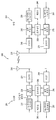
도 2는 무선 통신 시스템(200)에서의 기지국(205) 및 단말(210)의 구성을 도시한 블록도이다.
도 3은 무선통신 시스템의 일 에인 3GPP LTE/LTE-A 시스템에서 사용되는 무선 프레임의 구조를 예시한다.
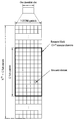
도 4는 무선통신 시스템의 일 예인 3GPP LTE/LTE-A 시스템의 하향링크 슬롯의 자원 그리드를 예시한 도면이다.
도 5는 무선통신 시스템의 일 예인 3GPP LTE/LTE-A 시스템의 하향링크 서브프레임의 구조를 예시한다.
도 6은 무선통신 시스템의 일 예인 3GPP LTE/LTE-A 시스템에서 사용되는 상향링크 서브프레임의 구조를 예시한다.
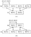
도 7은 캐리어 병합(Carrier Aggregation, CA) 통신 시스템을 예시한 도면이다.
도 8은 멀티플 TA 그룹이 설정된 경우를 예시하기 위한 도면이다.
도 9는 단말과 기지국 간의 PRACH 절차를 예시적으로 나타낸 도면이다.BRIEF DESCRIPTION OF THE DRAWINGS The accompanying drawings, which are included to provide a further understanding of the invention and are incorporated in and constitute a part of the specification, illustrate embodiments of the invention and, together with the description, serve to explain the principles of the invention.
1 is a diagram schematically illustrating an E-UMTS network structure as an example of a mobile communication system.
2 is a block diagram showing the configuration of the
3 illustrates the structure of a wireless frame used in a 3GPP LTE / LTE-A system at a wireless communication system.
4 is a diagram illustrating a resource grid of a downlink slot of a 3GPP LTE / LTE-A system, which is an example of a wireless communication system.
5 illustrates a structure of a downlink subframe of a 3GPP LTE / LTE-A system, which is an example of a wireless communication system.
FIG. 6 illustrates a structure of a UL subframe used in a 3GPP LTE / LTE-A system, which is an example of a wireless communication system.
7 is a diagram illustrating a Carrier Aggregation (CA) communication system.
8 is a diagram for illustrating a case where multiple TA groups are set.
9 is a diagram illustrating a PRACH procedure between a UE and a BS.
이하, 본 발명에 따른 바람직한 실시 형태를 첨부된 도면을 참조하여 상세하게 설명한다. 첨부된 도면과 함께 이하에 개시될 상세한 설명은 본 발명의 예시적인 실시형태를 설명하고자 하는 것이며, 본 발명이 실시될 수 있는 유일한 실시형태를 나타내고자 하는 것이 아니다. 이하의 상세한 설명은 본 발명의 완전한 이해를 제공하기 위해서 구체적 세부사항을 포함한다. 그러나, 당업자는 본 발명이 이러한 구체적 세부사항 없이도 실시될 수 있음을 안다. 예를 들어, 이하의 상세한 설명은 이동통신 시스템이 3GPP LTE, LTE-A 시스템인 경우를 가정하여 구체적으로 설명하나, 3GPP LTE, LTE-A 의 특유한 사항을 제외하고는 다른 임의의 이동통신 시스템에도 적용 가능하다.Hereinafter, preferred embodiments according to the present invention will be described in detail with reference to the accompanying drawings. DETAILED DESCRIPTION OF THE PREFERRED EMBODIMENTS The following detailed description, together with the accompanying drawings, is intended to illustrate exemplary embodiments of the invention and is not intended to represent the only embodiments in which the invention may be practiced. The following detailed description includes specific details in order to provide a thorough understanding of the present invention. However, those skilled in the art will appreciate that the present invention may be practiced without these specific details. For example, the following detailed description assumes that a mobile communication system is a 3GPP LTE and an LTE-A system. However, other than specific aspects of 3GPP LTE and LTE-A, Applicable.
몇몇 경우, 본 발명의 개념이 모호해지는 것을 피하기 위하여 공지의 구조 및 장치는 생략되거나, 각 구조 및 장치의 핵심기능을 중심으로 한 블록도 형식으로 도시될 수 있다. 또한, 본 명세서 전체에서 동일한 구성요소에 대해서는 동일한 도면 부호를 사용하여 설명한다.In some instances, well-known structures and devices may be omitted or may be shown in block diagram form, centering on the core functionality of each structure and device, to avoid obscuring the concepts of the present invention. In the following description, the same components are denoted by the same reference numerals throughout the specification.
아울러, 이하의 설명에 있어서 단말은 UE(User Equipment), MS(Mobile Station), AMS(Advanced Mobile Station) 등 이동 또는 고정형의 사용자단 기기를 통칭하는 것을 가정한다. 또한, 기지국은 Node B, eNode B, Base Station, AP(Access Point) 등 단말과 통신하는 네트워크 단의 임의의 노드를 통칭하는 것을 가정한다.In the following description, it is assumed that the UE collectively refers to a mobile stationary or stationary user equipment such as a UE (User Equipment), an MS (Mobile Station), and an AMS (Advanced Mobile Station). It is also assumed that the base station collectively refers to any node at a network end that communicates with a terminal such as a Node B, an eNode B, a base station, and an access point (AP).
이동 통신 시스템에서 단말(User Equipment)은 기지국으로부터 하향링크(Downlink)를 통해 정보를 수신할 수 있으며, 단말은 또한 상향링크(Uplink)를 통해 정보를 전송할 수 있다. 단말이 전송 또는 수신하는 정보로는 데이터 및 다양한 제어 정보가 있으며, 단말이 전송 또는 수신하는 정보의 종류 용도에 따라 다양한 물리 채널이 존재한다.In a mobile communication system, a user equipment can receive information through a downlink from a base station, and the terminal can also transmit information through an uplink. The information transmitted or received by the terminal includes data and various control information, and various physical channels exist depending on the type of information transmitted or received by the terminal.
도 2는 무선 통신 시스템(200)에서의 기지국(205) 및 단말(210)의 구성을 도시한 블록도이다.2 is a block diagram showing the configuration of the
무선 통신 시스템(200)을 간략화하여 나타내기 위해 하나의 기지국(205)과 하나의 단말(210)을 도시하였지만, 무선 통신 시스템(200)은 하나 이상의 기지국 및/또는 하나 이상의 단말을 포함할 수 있다.Although one
도 2를 참조하면, 기지국(205)은 송신(Tx) 데이터 프로세서(215), 심볼 변조기(220), 송신기(225), 송수신 안테나(230), 프로세서(280), 메모리(285), 수신기(290), 심볼 복조기(295), 수신 데이터 프로세서(297)를 포함할 수 있다. 그리고, 단말(210)은 송신(Tx) 데이터 프로세서(265), 심볼 변조기(270), 송신기(275), 송수신 안테나(235), 프로세서(255), 메모리(260), 수신기(240), 심볼 복조기(255), 수신 데이터 프로세서(250)를 포함할 수 있다. 안테나(230, 235)가 각각 기지국(205) 및 단말(210)에서 하나로 도시되어 있지만, 기지국(205) 및 단말(210)은 복수 개의 안테나를 구비하고 있다. 따라서, 본 발명에 따른 기지국(205) 및 단말(210)은 MIMO(Multiple Input Multiple Output) 시스템을 지원한다. 또한, 본 발명에 따른 기지국(205)은 SU-MIMO(Single User-MIMO) MU-MIMO(Multi User-MIMO) 방식 모두를 지원할 수 있다.2, a
하향링크 상에서, 송신 데이터 프로세서(215)는 트래픽 데이터를 수신하고, 수신한 트래픽 데이터를 포맷하여, 코딩하고, 코딩된 트래픽 데이터를 인터리빙하고 변조하여(또는 심볼 매핑하여), 변조 심볼들("데이터 심볼들")을 제공한다. 심볼 변조기(220)는 이 데이터 심볼들과 파일럿 심볼들을 수신 및 처리하여, 심볼들의 스트림을 제공한다.On the downlink, the transmit
심볼 변조기(220)는, 데이터 및 파일럿 심볼들을 다중화하여 이를 송신기(225)로 전송한다. 이때, 각각의 송신 심볼은 데이터 심볼, 파일럿 심볼, 또는 제로의 신호 값일 수도 있다. 각각의 심볼 주기에서, 파일럿 심볼들이 연속적으로 송신될 수도 있다. 파일럿 심볼들은 주파수 분할 다중화(FDM), 직교 주파수 분할 다중화(OFDM), 시분할 다중화(TDM), 또는 코드 분할 다중화(CDM) 심볼일 수 있다.The symbol modulator 220 multiplexes the data and pilot symbols and transmits it to the
송신기(225)는 심볼들의 스트림을 수신하여 이를 하나 이상의 아날로그 신호들로 변환하고, 또한, 이 아날로그 신호들을 추가적으로 조절하여(예를 들어, 증폭, 필터링, 및 주파수 업 컨버팅(upconverting) 하여, 무선 채널을 통한 송신에 적합한 하향링크 신호를 발생시킨다. 그러면, 안테나(230)는 발생된 하향링크 신호를 단말로 전송한다.
단말(210)의 구성에서, 안테나(235)는 기지국으로부터의 하향링크 신호를 수신하여 수신된 신호를 수신기(240)로 제공한다. 수신기(240)는 수신된 신호를 조정하고(예를 들어, 필터링, 증폭, 및 주파수 다운컨버팅(downconverting)), 조정된 신호를 디지털화하여 샘플들을 획득한다. 심볼 복조기(245)는 수신된 파일럿 심볼들을 복조하여 채널 추정을 위해 이를 프로세서(255)로 제공한다.In the configuration of the terminal 210, the
또한, 심볼 복조기(245)는 프로세서(255)로부터 하향링크에 대한 주파수 응답 추정치를 수신하고, 수신된 데이터 심볼들에 대해 데이터 복조를 수행하여, (송신된 데이터 심볼들의 추정치들인) 데이터 심볼 추정치를 획득하고, 데이터 심볼 추정치들을 수신(Rx) 데이터 프로세서(250)로 제공한다. 수신 데이터 프로세서(250)는 데이터 심볼 추정치들을 복조(즉, 심볼 디-매핑(demapping))하고, 디인터리빙(deinterleaving)하고, 디코딩하여, 전송된 트래픽 데이터를 복구한다.
심볼 복조기(245) 및 수신 데이터 프로세서(250)에 의한 처리는 각각 기지국(205)에서의 심볼 변조기(220) 및 송신 데이터 프로세서(215)에 의한 처리에 대해 상보적이다.The processing by
단말(210)은 상향링크 상에서, 송신 데이터 프로세서(265)는 트래픽 데이터를 처리하여, 데이터 심볼들을 제공한다. 심볼 변조기(270)는 데이터 심볼들을 수신하여 다중화하고, 변조를 수행하여, 심볼들의 스트림을 송신기(275)로 제공할 수 있다. 송신기(275)는 심볼들의 스트림을 수신 및 처리하여, 상향링크 신호를 발생시킨다. 그리고 안테나(235)는 발생된 상향링크 신호를 기지국(205)으로 전송한다.On the uplink, the terminal 210 processes the traffic data and provides data symbols.
기지국(205)에서, 단말(210)로부터 상향링크 신호가 안테나(230)를 통해 수신되고, 수신기(290)는 수신한 상향링크 신호를 처리되어 샘플들을 획득한다. 이어서, 심볼 복조기(295)는 이 샘플들을 처리하여, 상향링크에 대해 수신된 파일럿 심볼들 및 데이터 심볼 추정치를 제공한다. 수신 데이터 프로세서(297)는 데이터 심볼 추정치를 처리하여, 단말(210)로부터 전송된 트래픽 데이터를 복구한다.In the
단말(210) 및 기지국(205) 각각의 프로세서(255, 280)는 각각 단말(210) 및 기지국(205)에서의 동작을 지시(예를 들어, 제어, 조정, 관리 등)한다. 각각의 프로세서들(255, 280)은 프로그램 코드들 및 데이터를 저장하는 메모리 유닛(260, 285)들과 연결될 수 있다. 메모리(260, 285)는 프로세서(280)에 연결되어 오퍼레이팅 시스템, 어플리케이션, 및 일반 파일(general files)들을 저장한다.The
프로세서(255, 280)는 컨트롤러(controller), 마이크로 컨트롤러(microcontroller), 마이크로 프로세서(microprocessor), 마이크로 컴퓨터(microcomputer) 등으로도 호칭될 수 있다. 한편, 프로세서(255, 280)는 하드웨어(hardware) 또는 펌웨어(firmware), 소프트웨어, 또는 이들의 결합에 의해 구현될 수 있다. 하드웨어를 이용하여 본 발명의 실시예를 구현하는 경우에는, 본 발명을 수행하도록 구성된 ASICs(application specific integrated circuits) 또는 DSPs(digital signal processors), DSPDs(digital signal processing devices), PLDs(programmable logic devices), FPGAs(field programmable gate arrays) 등이 프로세서(255, 280)에 구비될 수 있다.
한편, 펌웨어나 소프트웨어를 이용하여 본 발명의 실시예들을 구현하는 경우에는 본 발명의 기능 또는 동작들을 수행하는 모듈, 절차 또는 함수 등을 포함하도록 펌웨어나 소프트웨어가 구성될 수 있으며, 본 발명을 수행할 수 있도록 구성된 펌웨어 또는 소프트웨어는 프로세서(255, 280) 내에 구비되거나 메모리(260, 285)에 저장되어 프로세서(255, 280)에 의해 구동될 수 있다.Meanwhile, when implementing embodiments of the present invention using firmware or software, firmware or software may be configured to include modules, procedures, or functions that perform the functions or operations of the present invention. Firmware or software configured to be stored in
단말과 기지국이 무선 통신 시스템(네트워크) 사이의 무선 인터페이스 프로토콜의 레이어들은 통신 시스템에서 잘 알려진 OSI(open system interconnection) 모델의 하위 3개 레이어를 기초로 제 1 레이어(L1), 제 2 레이어(L2), 및 제 3 레이어(L3)로 분류될 수 있다. 물리 레이어는 상기 제 1 레이어에 속하며, 물리 채널을 통해 정보 전송 서비스를 제공한다. RRC(Radio Resource Control) 레이어는 상기 제 3 레이어에 속하며 UE와 네트워크 사이의 제어 무선 자원들을 제공한다. 단말, 기지국은 무선 통신 네트워크와 RRC 레이어를 통해 RRC 메시지들을 교환할 수 있다.Layers of a wireless interface protocol between a terminal and a base station and a wireless communication system (network) are divided into a first layer (L1), a second layer (L2) based on the lower three layers of an open system interconnection ), And a third layer (L3). The physical layer belongs to the first layer and provides an information transmission service through a physical channel. An RRC (Radio Resource Control) layer belongs to the third layer and provides control radio resources between the UE and the network. The UE and the base station can exchange RRC messages through the RRC layer with the wireless communication network.
도 3은 무선통신 시스템의 일 에인 3GPP LTE/LTE-A 시스템에서 사용되는 무선 프레임의 구조를 예시한다.3 illustrates the structure of a wireless frame used in a 3GPP LTE / LTE-A system at a wireless communication system.
셀룰라 OFDM 무선 패킷 통신 시스템에서, 상향링크/하향링크 데이터 패킷 전송은 서브프레임(subframe) 단위로 이루어지며, 한 서브프레임은 다수의 OFDM 심볼을 포함하는 일정 시간 구간으로 정의된다. 3GPP LTE 표준에서는 FDD(Frequency Division Duplex)에 적용 가능한 타입 1 무선 프레임(radio frame) 구조와 TDD(Time Division Duplex)에 적용 가능한 타입 2의 무선 프레임 구조를 지원한다.In a cellular OFDM wireless packet communication system, uplink / downlink data packet transmission is performed on a subframe basis, and one subframe is defined as a predetermined time interval including a plurality of OFDM symbols. The 3GPP LTE standard supports a
도 3(a)는 타입 1 무선 프레임의 구조를 예시한다. 하향링크 무선 프레임(radio frame)은 10개의 서브프레임(subframe)으로 구성되고, 하나의 서브프레임은 시간 영역(time domain)에서 2개의 슬롯(slot)으로 구성된다. 하나의 서브프레임이 전송되는 데 걸리는 시간을 TTI(transmission time interval)라 한다. 예를 들어 하나의 서브프레임의 길이는 1ms이고, 하나의 슬롯의 길이는 0.5ms 일 수 있다. 하나의 슬롯은 시간 영역에서 복수의 OFDM 심볼을 포함하고, 주파수 영역에서 다수의 자원블록(Resource Block, RB)을 포함한다. 3GPP LTE 시스템에서는 하향링크에서 OFDMA 를 사용하므로, OFDM 심볼이 하나의 심볼 구간을 나타낸다. OFDM 심볼은 또한 SC-FDMA 심볼 또는 심볼 구간으로 칭하여질 수도 있다. 자원 할당 단위로서의 자원 블록(RB)은 하나의 슬롯에서 복수개의 연속적인 부반송파(subcarrier)를 포함할 수 있다.3 (a) illustrates the structure of a
하나의 슬롯에 포함되는 OFDM 심볼의 수는 CP(Cyclic Prefix)의 구성(configuration)에 따라 달라질 수 있다. CP에는 확장된 CP(extended CP)와 표준 CP(normal CP)가 있다. 예를 들어, OFDM 심볼이 표준 CP에 의해 구성된 경우, 하나의 슬롯에 포함되는 OFDM 심볼의 수는 7개일 수 있다. OFDM 심볼이 확장된 CP에 의해 구성된 경우, 한 OFDM 심볼의 길이가 늘어나므로, 한 슬롯에 포함되는 OFDM 심볼의 수는 표준 CP인 경우보다 적다. 확장된 CP의 경우에, 예를 들어, 하나의 슬롯에 포함되는 OFDM 심볼의 수는 6개일 수 있다. 단말이 빠른 속도로 이동하는 등의 경우와 같이 채널상태가 불안정한 경우, 심볼간 간섭을 더욱 줄이기 위해 확장된 CP가 사용될 수 있다.The number of OFDM symbols included in one slot may vary according to the configuration of a CP (Cyclic Prefix). CP has an extended CP and a normal CP. For example, when an OFDM symbol is configured by a standard CP, the number of OFDM symbols included in one slot may be seven. When the OFDM symbol is configured by an extended CP, the length of one OFDM symbol is increased, so that the number of OFDM symbols included in one slot is smaller than that in the standard CP. In the case of the extended CP, for example, the number of OFDM symbols included in one slot may be six. If the channel condition is unstable, such as when the UE moves at a high speed, an extended CP may be used to further reduce inter-symbol interference.
표준 CP가 사용되는 경우 하나의 슬롯은 7개의 OFDM 심볼을 포함하므로, 하나의 서브프레임은 14개의 OFDM 심볼을 포함한다. 이때, 각 서브프레임의 처음 최대 3 개의 OFDM 심볼은 PDCCH(physical downlink control channel)에 할당되고, 나머지 OFDM 심볼은 PDSCH(physical downlink shared channel)에 할당될 수 있다.One slot includes 7 OFDM symbols when a standard CP is used, so one subframe includes 14 OFDM symbols. At this time, the first three OFDM symbols at the beginning of each subframe may be allocated to a physical downlink control channel (PDCCH), and the remaining OFDM symbols may be allocated to a physical downlink shared channel (PDSCH).
도 3(b)는 타입 2 무선 프레임의 구조를 예시한다. 타입 2 무선 프레임은 2개의 하프 프레임(half frame)으로 구성되며, 각 하프 프레임은 5개의 서브프레임과 DwPTS(Downlink Pilot Time Slot), 보호구간(Guard Period, GP), UpPTS(Uplink Pilot Time Slot)로 구성되며, 이 중 1개의 서브프레임은 2개의 슬롯으로 구성된다. DwPTS는 단말에서의 초기 셀 탐색, 동기화 또는 채널 추정에 사용된다. UpPTS는 기지국에서의 채널 추정과 단말의 상향링크 전송 동기를 맞추는 데 사용된다. 보호구간은 상향링크와 하향링크 사이에 하향링크 신호의 다중경로 지연으로 인해 상향링크에서 생기는 간섭을 제거하기 위한 구간이다.3 (b) illustrates the structure of a
각 하프 프레임은 5개의 서브프레임을 포함하고 있고, "D"라고 표시된 서브프레임은 하향링크 전송을 위한 서브프레임, "U"라고 표시된 서브프레임은 상향링크 전송을 위한 서브프레임이며, "S"라고 표시된 서브프레임은 DwPTS(Downlink Pilot Time Slot), 보호구간(Guard Period, GP), UpPTS(Uplink Pilot Time Slot)로 구성되는 특별 서브프레임이다. DwPTS는 단말에서의 초기 셀 탐색, 동기화 또는 채널 추정에 사용된다. UpPTS는 기지국에서의 채널 추정과 단말의 상향 전송 동기를 맞추는 데 사용된다. 보호구간은 상향링크와 하향링크 사이에 하향링크 신호의 다중경로 지연으로 인해 상향링크에서 생기는 간섭을 제거하기 위한 구간이다.Each half frame includes five subframes. A subframe indicated by "D" is a subframe for downlink transmission, a subframe indicated by "U" is a subframe for uplink transmission, and "S" The displayed subframe is a special subframe composed of a downlink pilot time slot (DwPTS), a guard period (GP), and an uplink pilot time slot (UpPTS). The DwPTS is used for initial cell search, synchronization, or channel estimation in the UE. UpPTS is used to match the channel estimation at the base station and the uplink transmission synchronization of the terminal. The guard interval is a period for eliminating the interference occurring in the uplink due to the multi-path delay of the downlink signal between the uplink and the downlink.
5ms 하향링크-상향링크 스위치-포인트 주기인 경우에 특별 서브프레임(S)은 하프-프레임 마다 존재하고, 5ms 하향링크-상향링크 스위치-포인트 주기인 경우에는 첫 번째 하프-프레임에만 존재한다. 서브프레임 인덱스 0 및 5(subframe 0 and 5) 및 DwPTS는 하향링크 전송만을 위한 구간이다. UpPTS 및 특별 서브프레임에 바로 이어지는 서브프레임은 항상 상향링크 전송을 위한 구간이다. 멀티-셀 들이 병합된(aggregated) 경우, 단말은 모든 셀들에 거쳐 동일한 상향링크-하향링크 구성임을 가정할 수 있고, 서로 다른 셀들에서의 특별 서브프레임의 보호 구간은 적어도 1456Ts 오버랩된다. 무선 프레임의 구조는 예시에 불과하고, 무선 프레임에 포함되는 서브프레임의 수 또는 서브프레임에 포함되는 슬롯의 수, 슬롯에 포함되는 심볼의 수는 다양하게 변경될 수 있다.In the case of a 5 ms downlink-uplink switch-point period, the special sub-frame S exists for each half-frame and only exists in the first half-frame for a 5 ms downlink-uplink switch-point period.
다음 표 1은 특별 프레임의 구성(DwPTS/GP/UpPTS의 길이)을 나타낸 표이다Table 1 below is a table showing the composition of the special frame (DwPTS / GP / UpPTS length)

다음 표 2는 상향링크-하향링크 구성을 나타낸 표이다.Table 2 below shows the uplink-downlink configuration.

표 2를 참조하면, 3GPP LTE 시스템에서는 타입 2 프레임 구조에서 상향링크-하향링크 구성(configuration)에는 7가지가 있다. 각 구성 별로 하향링크 서브프레임, 특별 프레임, 상향링크 서브프레임의 위치 또는 개수가 다를 수 있다. 이하에서는 표 2에 나타낸 타입 2 프레임 구조의 상향링크-하향링크 구성(configuration)들에 기초하여 본 발명의 다양한 실시예들을 기술할 것이다.Referring to Table 2, there are seven types of uplink-downlink configuration in the
무선 프레임의 구조는 예시에 불과하고, 무선 프레임에 포함되는 서브프레임의 수 또는 서브프레임에 포함되는 슬롯의 수, 슬롯에 포함되는 심볼의 수는 다양하게 변경될 수 있다.The structure of the radio frame is merely an example, and the number of subframes included in a radio frame, the number of slots included in a subframe, and the number of symbols included in a slot can be variously changed.
도 4는 무선통신 시스템의 일 예인 3GPP LTE/LTE-A 시스템의 하향링크 슬롯의 자원 그리드를 예시한 도면이다.4 is a diagram illustrating a resource grid of a downlink slot of a 3GPP LTE / LTE-A system, which is an example of a wireless communication system.
도 4를 참조하면, 하향링크 슬롯은 시간 도메인에서 복수의 OFDM 심볼을 포함한다. 하나의 하향링크 슬롯은 7(혹은 6)개의 OFDM 심볼을 포함하고 자원 블록은 주파수 도메인에서 12개의 부반송파를 포함할 수 있다. 자원 그리드 상의 각 요소(element)는 자원 요소(Resource Element, RE)로 지칭된다. 하나의 RB는 12×7(6)개의 RE를 포함한다. 하향링크 슬롯에 포함되는 RB의 개수 NRB는 하향링크 전송 대역에 의존한다. 상향링크 슬롯의 구조는 하향링크 슬롯의 구조와 동일하되, OFDM 심볼이 SC-FDMA 심볼로 대체된다.Referring to FIG. 4, the downlink slot includes a plurality of OFDM symbols in the time domain. One downlink slot includes 7 (or 6) OFDM symbols and the resource block may include 12 subcarriers in the frequency domain. Each element on the resource grid is referred to as a Resource Element (RE). One RB includes 12 x 7 (6) REs. The number NRB of RBs included in the downlink slot depends on the downlink transmission band. The structure of the uplink slot is the same as the structure of the downlink slot, and the OFDM symbol is replaced with the SC-FDMA symbol.
도 5는 무선통신 시스템의 일 예인 3GPP LTE/LTE-A 시스템의 하향링크 서브프레임의 구조를 예시한다.5 illustrates a structure of a downlink subframe of a 3GPP LTE / LTE-A system, which is an example of a wireless communication system.
도 5를 참조하면, 서브프레임의 첫 번째 슬롯에서 앞부분에 위치한 최대 3(4)개의 OFDM 심볼은 제어 채널이 할당되는 제어 영역에 대응한다. 남은 OFDM 심볼은 PDSCH(Physical Downlink Shared CHancel)가 할당되는 데이터 영역에 해당한다. LTE에서 사용되는 하향링크 제어 채널의 예는 PCFICH(Physical Control Format Indicator Channel), PDCCH(Physical Downlink Control Channel), PHICH(Physical hybrid ARQ indicator Channel) 등을 포함한다. PCFICH는 서브프레임의 첫 번째 OFDM 심볼에서 전송되고 서브프레임 내에서 제어 채널의 전송에 사용되는 OFDM 심볼의 개수에 관한 정보를 나른다. PHICH는 상향링크 전송에 대한 응답으로 HARQ ACK/NACK(Hybrid Automatic Repeat request acknowledgment/negative-acknowledgment) 신호를 나른다.Referring to FIG. 5, a maximum of 3 (4) OFDM symbols located at a first position in a first slot of a subframe corresponds to a control region to which a control channel is allocated. The remaining OFDM symbol corresponds to a data area to which PDSCH (Physical Downlink Shared CHannel) is allocated. Examples of downlink control channels used in LTE include Physical Control Format Indicator Channel (PCFICH), Physical Downlink Control Channel (PDCCH), Physical Hybrid ARQ Indicator Channel (PHICH), and the like. The PCFICH carries information about the number of OFDM symbols transmitted in the first OFDM symbol of the subframe and used for transmission of the control channel in the subframe. The PHICH carries a HARQ ACK / NACK (Hybrid Automatic Repeat request acknowledgment / negative-acknowledgment) signal in response to the uplink transmission.
PDCCH를 통해 전송되는 제어 정보를 DCI(Downlink Control Information)라고 한다. DCI 포맷은 상향링크용으로 포맷 0, 하향링크용으로 포맷 1, 1A, 1B, 1C, 1D, 2, 2A, 3, 3A 등의 포맷이 정의되어 있다. DCI 포맷은 용도에 따라 호핑 플래그(hopping flag), RB 할당, MCS(modulation coding scheme), RV(redundancy version), NDI(new data indicator), TPC(transmit power control), 사이클릭 쉬프트 DM RS(demodulation reference signal), CQI (channel quality information) 요청, HARQ 프로세스 번호, TPMI(transmitted precoding matrix indicator), PMI(precoding matrix indicator) 확인(confirmation) 등의 정보를 선택적으로 포함한다.The control information transmitted through the PDCCH is called DCI (Downlink Control Information). The format of DCI format is defined as
PDCCH는 하향링크 공유 채널(downlink shared channel, DL-SCH)의 전송 포맷 및 자원 할당 정보, 상향링크 공유 채널(uplink shared channel, UL-SCH)의 전송 포맷 및 자원 할당 정보, 페이징 채널(paging channel, PCH) 상의 페이징 정보, DL-SCH 상의 시스템 정보, PDSCH 상에서 전송되는 랜덤 접속 응답과 같은 상위-계층 제어 메시지의 자원 할당 정보, 단말 그룹 내의 개별 단말들에 대한 Tx 파워 제어 명령 세트, Tx 파워 제어 명령, VoIP(Voice over IP)의 활성화 지시 정보 등을 나른다. 복수의 PDCCH가 제어 영역 내에서 전송될 수 있다. 단말은 복수의 PDCCH를 모니터링 할 수 있다. PDCCH는 하나 또는 복수의 연속된 제어 채널 요소(control channel element, CCE)들의 집합(aggregation) 상에서 전송된다. CCE는 PDCCH에 무선 채널 상태에 기초한 코딩 레이트를 제공하는데 사용되는 논리적 할당 유닛이다. CCE는 복수의 자원 요소 그룹(resource element group, REG)에 대응한다. PDCCH의 포맷 및 PDCCH 비트의 개수는 CCE의 개수에 따라 결정된다. 기지국은 단말에게 전송될 DCI에 따라 PDCCH 포맷을 결정하고, 제어 정보에 CRC(cyclic redundancy check)를 부가한다. CRC는 PDCCH의 소유자 또는 사용 목적에 따라 식별자(예, RNTI(radio network temporary identifier))로 마스킹 된다. 예를 들어, PDCCH가 특정 단말을 위한 것일 경우, 해당 단말의 식별자(예, cell-RNTI (C-RNTI))가 CRC에 마스킹 될 수 있다. PDCCH가 페이징 메시지를 위한 것일 경우, 페이징 식별자(예, paging-RNTI (P-RNTI))가 CRC에 마스킹 될 수 있다. PDCCH가 시스템 정보(보다 구체적으로, 시스템 정보 블록(system information block, SIC))를 위한 것일 경우, SI-RNTI(system information RNTI)가 CRC에 마스킹 될 수 있다. PDCCH가 랜덤 접속 응답을 위한 것일 경우, RA-RNTI(random access-RNTI)가 CRC에 마스킹 될 수 있다.PDCCH includes a transmission format and resource allocation information of a downlink shared channel (DL-SCH), a transmission format and resource allocation information of an uplink shared channel (UL-SCH), a paging channel, Layer control message such as random access response transmitted on the PDSCH, Tx power control instruction set for individual terminals in the terminal group, Tx power control command , Voice over IP (VoIP) activation indication information, and the like. A plurality of PDCCHs may be transmitted within the control domain. The UE can monitor a plurality of PDCCHs. The PDCCH is transmitted on an aggregation of one or a plurality of consecutive control channel elements (CCEs). The CCE is a logical allocation unit used to provide the PDCCH with a coding rate based on radio channel conditions. The CCE corresponds to a plurality of resource element groups (REG). The format of the PDCCH and the number of PDCCH bits are determined according to the number of CCEs. The base station determines the PDCCH format according to the DCI to be transmitted to the UE, and adds a CRC (cyclic redundancy check) to the control information. The CRC is masked with an identifier (e.g., radio network temporary identifier (RNTI)) according to the owner of the PDCCH or the purpose of use. For example, if the PDCCH is for a particular terminal, the identifier of the terminal (e.g., cell-RNTI (C-RNTI)) may be masked to the CRC. If the PDCCH is for a paging message, the paging identifier (e.g., paging-RNTI (P-RNTI)) may be masked to the CRC. If the PDCCH is for system information (more specifically, a system information block (SIC)), the system information RNTI (SI-RNTI) may be masked to the CRC. If the PDCCH is for a random access response, a random access-RNTI (RA-RNTI) may be masked in the CRC.
도 6은 무선통신 시스템의 일 예인 3GPP LTE/LTE-A 시스템에서 사용되는 상향링크 서브프레임의 구조를 예시한다.FIG. 6 illustrates a structure of a UL subframe used in a 3GPP LTE / LTE-A system, which is an example of a wireless communication system.
도 6을 참조하면, 상향링크 서브프레임은 복수(예, 2개)의 슬롯을 포함한다. 슬롯은 CP 길이에 따라 서로 다른 수의 SC-FDMA 심볼을 포함할 수 있다. 상향링크 서브프레임은 주파수 영역에서 데이터 영역과 제어 영역으로 구분된다. 데이터 영역은 PUSCH를 포함하고 음성 등의 데이터 신호를 전송하는데 사용된다. 제어 영역은 PUCCH를 포함하고 상향링크 제어 정보(Uplink Control Information, UCI)를 전송하는데 사용된다. PUCCH는 주파수 축에서 데이터 영역의 양끝 부분에 위치한 RB 쌍(RB pair)을 포함하며 슬롯을 경계로 호핑한다.Referring to FIG. 6, the uplink subframe includes a plurality of (e.g., two) slots. The slot may include a different number of SC-FDMA symbols depending on the CP length. The UL subframe is divided into a data region and a control region in the frequency domain. The data area includes a PUSCH and is used to transmit a data signal such as voice. The control region includes a PUCCH and is used to transmit uplink control information (UCI). The PUCCH includes an RB pair (RB pair) located at both ends of the data area on the frequency axis and hopping the slot to the boundary.
PUCCH는 다음의 제어 정보를 전송하는데 사용될 수 있다.The PUCCH may be used to transmit the following control information.
- SR(Scheduling Request): 상향링크 UL-SCH 자원을 요청하는데 사용되는 정보이다. OOK(On-Off Keying) 방식을 이용하여 전송된다.- SR (Scheduling Request): Information used for requesting uplink UL-SCH resources. OOK (On-Off Keying) method.
- HARQ ACK/NACK: PDSCH 상의 하향링크 데이터 패킷에 대한 응답 신호이다. 하향링크 데이터 패킷이 성공적으로 수신되었는지 여부를 나타낸다. 단일 하향링크 코드워드(CodeWord, CW)에 대한 응답으로 ACK/NACK 1비트가 전송되고, 두 개의 하향링크 코드워드에 대한 응답으로 ACK/NACK 2비트가 전송된다.- HARQ ACK / NACK: This is a response signal to the downlink data packet on the PDSCH. Indicates whether the downlink data packet has been successfully received. In response to a single downlink code word (CodeWord, CW), one bit of ACK / NACK is transmitted and two bits of ACK / NACK are transmitted in response to two downlink codewords.
- CQI(Channel Quality Indicator): 하향링크 채널에 대한 피드백 정보이다. MIMO(Multiple Input Multiple Output) 관련 피드백 정보는 RI(Rank Indicator), PMI(Precoding Matrix Indicator), PTI(Precoding Type Indicator) 등을 포함한다. 서브프레임 당 20비트가 사용된다.- CQI (Channel Quality Indicator): Feedback information on the downlink channel. The feedback information related to Multiple Input Multiple Output (MIMO) includes Rank Indicator (RI), Precoding Matrix Indicator (PMI), and Precoding Type Indicator (PTI). 20 bits per subframe are used.
단말이 서브프레임에서 전송할 수 있는 제어 정보(UCI)의 양은 제어 정보 전송에 가용한 SC-FDMA의 개수에 의존한다. 제어 정보 전송에 가용한 SC-FDMA는 서브프레임에서 참조 신호 전송을 위한 SC-FDMA 심볼을 제외하고 남은 SC-FDMA 심볼을 의미하고, SRS(Sounding Reference Signal)가 설정된 서브프레임의 경우 서브프레임의 마지막 SC-FDMA 심볼도 제외된다. 참조 신호는 PUCCH의 코히어런트 검출에 사용된다. PUCCH는 전송되는 정보에 따라 7개의 포맷을 지원한다.The amount of control information (UCI) that the UE can transmit in the subframe depends on the number of SC-FDMAs available for control information transmission. The SC-FDMA available for transmission of control information means the remaining SC-FDMA symbol excluding the SC-FDMA symbol for reference signal transmission in the subframe. In the case of the subframe in which the SRS (Sounding Reference Signal) is set, SC-FDMA symbols are excluded. The reference signal is used for coherent detection of the PUCCH. PUCCH supports 7 formats according to the information to be transmitted.
표 3은 LTE에서 PUCCH 포맷과 UCI의 맵핑 관계를 나타낸다.Table 3 shows the mapping relationship between the PUCCH format and UCI in LTE.

도 7은 캐리어 병합(Carrier Aggregation, CA) 통신 시스템을 예시한 도면이다.7 is a diagram illustrating a Carrier Aggregation (CA) communication system.
LTE-A 시스템은 보다 넓은 주파수 대역폭을 위해 복수의 상/하향링크 주파수 대역폭을 모아 더 큰 상/하향링크 대역폭을 사용하는 캐리어 병합(carrier aggregation 또는 bandwidth aggregation) 기술을 사용한다. 각각의 작은 주파수 대역폭은 콤포넌트 캐리어(Component Carrier, CC)를 이용해 전송된다. 콤포넌트 캐리어는 해당 주파수 블록을 위한 캐리어 주파수 (또는 중심 캐리어, 중심 주파수)로 이해될 수 있다.The LTE-A system uses a carrier aggregation or bandwidth aggregation technique that uses a larger uplink / downlink bandwidth to aggregate a plurality of uplink / downlink frequency bandwidths for a wider frequency bandwidth. Each small frequency bandwidth is transmitted using a component carrier (CC). The component carrier can be understood as a carrier frequency (or center carrier, center frequency) for that frequency block.
각각의 CC들은 주파수 영역에서 서로 인접하거나 비-인접할 수 있다. CC의 대역폭은 기존 시스템과의 역호환(backward compatibility)을 위해 기존 시스템의 대역폭으로 제한될 수 있다. 예를 들어, 기존의 3GPP LTE 시스템에서는 {1.4, 3, 5, 10, 15, 20}MHz 대역폭을 지원하며, LTE_A에서는 LTE에서 지원하는 상기의 대역폭들만을 이용하여 20MHz보다 큰 대역폭을 지원할 수 있다. 각 CC 의 대역폭은 독립적으로 정해질 수 있다. UL CC의 개수와 DL CC의 개수가 다른 비대칭 캐리어 병합도 가능하다. DL CC/UL CC 링크는 시스템에 고정되어 있거나 반-정적으로 구성될 수 있다. 예를 들어, 도 6(a)와 같이 DL CC 4개 UL CC 2개인 경우 DL CC:UL CC=2:1로 대응되도록 DL-UL 링키지 구성이 가능하다. 유사하게, 도 6(b)와 같이 DL CC 2개 UL CC 4개인 경우 DL CC:UL CC=1:2로 대응되도록 DL-UL 링키지 구성이 가능하다. 도시한 바와 달리, DL CC의 개수와 UL CC의 개수가 동일한 대칭 캐리어 병합도 가능하고, 이 경우 DL CC:UL CC=1:1의 DL-UL 링키지 구성도 가능하다.Each CC may be adjacent or non-adjacent to one another in the frequency domain. The bandwidth of the CC can be limited to the bandwidth of the existing system for backward compatibility with existing systems. For example, the existing 3GPP LTE system supports {1.4, 3, 5, 10, 15, 20} MHz bandwidths and LTE_A can support bandwidths greater than 20 MHz using only those bandwidths supported by LTE . The bandwidth of each CC can be set independently. It is also possible to combine asymmetric carriers with different numbers of UL CCs and DL CCs. The DL CC / UL CC link can be fixed to the system or semi-static. For example, as shown in FIG. 6 (a), a DL-UL linkage configuration is possible so that
또한, 시스템 전체 대역폭이 N개의 CC로 구성되더라도 특정 단말이 모니터링/수신할 수 있는 주파수 대역은 M(<N)개의 CC로 한정될 수 있다. 캐리어 병합에 대한 다양한 파라미터는 셀 특정(cell-specific), 단말 그룹 특정(UE group-specific) 또는 단말 특정(UE-specific) 방식으로 설정될 수 있다. 한편, 제어 정보는 특정 CC를 통해서만 송수신 되도록 설정될 수 있다. 특정 CC를 프라이머리 CC(Primary CC, PCC)로 지칭하고, 나머지 CC를 세컨더리 CC(Secondary CC, SCC)로 지칭할 수 있다.Also, even if the total bandwidth of the system is composed of N CCs, the frequency band that a specific terminal can monitor / receive can be limited to M (<N) CCs. The various parameters for carrier merging may be set in a cell-specific, UE group-specific or UE-specific manner. On the other hand, the control information can be set to be transmitted and received only through a specific CC. A specific CC may be referred to as a primary CC (PCC), and the remaining CC may be referred to as a secondary CC (SCC).
LTE-A는 무선 자원을 관리하기 위해 셀(cell)의 개념을 사용한다. 셀은 하향링크 자원과 상향링크 자원의 조합으로 정의되며, 상향링크 자원은 필수 요소는 아니다. 따라서, 셀은 하향링크 자원 단독, 또는 하향링크 자원과 상향링크 자원으로 구성될 수 있다. 캐리어 병합이 지원되는 경우, 하향링크 자원의 캐리어 주파수(또는, DL CC)와 상향링크 자원의 캐리어 주파수(또는, UL CC) 사이의 링키지(linkage)는 시스템 정보에 의해 지시될 수 있다. 프라이머리 주파수(또는 PCC) 상에서 동작하는 셀을 프라이머리 셀(Primary Cell, PCell)로 지칭하고, 세컨더리 주파수(또는 SCC) 상에서 동작하는 셀을 세컨더리 셀(Secondary Cell, SCell)로 지칭할 수 있다.LTE-A uses the concept of a cell to manage radio resources. A cell is defined as a combination of a downlink resource and an uplink resource, and an uplink resource is not essential. Therefore, the cell can be composed of downlink resources alone or downlink resources and uplink resources. If carrier merging is supported, the linkage between the carrier frequency (or DL CC) of the downlink resource and the carrier frequency (or UL CC) of the uplink resource may be indicated by the system information. A cell operating on a primary frequency (or PCC) may be referred to as a primary cell (PCell), and a cell operating on a secondary frequency (or SCC) may be referred to as a secondary cell (SCell).
PCell은 단말이 초기 연결 설정(initial connection establishment) 과정을 수행하거나 연결 재-설정 과정을 수행하는데 사용된다. PCell은 핸드오버 과정에서 지시된 셀을 지칭할 수도 있다. SCell은 RRC(Radio Resource Control) 연결이 설정이 이루어진 이후에 구성 가능하고 추가적인 무선 자원을 제공하는데 사용될 수 있다. PCell과 SCell은 서빙 셀로 통칭될 수 있다. 따라서, RRC_CONNECTED 상태에 있지만 캐리어 병합이 설정되지 않았거나 캐리어 병합을 지원하지 않는 단말의 경우, PCell로만 구성된 서빙 셀이 단 하나 존재한다. 반면, RRC_CONNECTED 상태에 있고 캐리어 병합이 설정된 단말의 경우, 하나 이상의 서빙 셀이 존재하고, 전체 서빙 셀에는 PCell과 전체 SCell이 포함된다. 캐리어 병합을 위해, 네트워크는 초기 보안 활성화(initial security activation) 과정이 개시된 이후, 연결 설정 과정에서 초기에 구성되는 PCell에 부가하여 하나 이상의 SCell을 캐리어 병합을 지원하는 단말을 위해 구성할 수 있다.PCell is used for the UE to perform an initial connection establishment process or a connection re-establishment process. The PCell may refer to the cell indicated in the handover process. SCell can be used to provide additional radio resources that can be configured and configured after a Radio Resource Control (RRC) connection is established. PCell and SCell can be collectively referred to as serving cells. Therefore, in the case of a terminal that is in the RRC_CONNECTED state but no carrier merge is set or does not support carrier merging, there is only one serving cell consisting only of PCell. On the other hand, in the case of the UE in the RRC_CONNECTED state and the merge of the carriers, there is one or more serving cells, and the entire serving cell includes the PCell and the entire SCell. In order to merge the carriers, the network may configure one or more SCells for the UEs supporting carrier merging in addition to the PCells initially configured in the connection establishment process after the initial security activation process is started.
하나의 캐리어를 사용하는 기존의 LTE 시스템과는 다르게 다수 개의 콤포넌트 캐리어(CC)를 사용하는 캐리어 어그리게이션에서는 콤포넌트 캐리어를 효과적으로 관리하는 방법이 필요하게 되었다. 콤포넌트 캐리어를 효율적으로 관리하기 위해, 콤포넌트 캐리어를 역할과 특징에 따라 분류할 수 있다. 캐리어 어그리게이션에서는 멀티 캐리어가 주 콤포넌트 캐리어(Primary Component Carrier, PCC)와 부 콤포넌트 캐리어(Secondary Component Carrier, SCC)로 나누어질 수 있으며, 이는 단말-특정(UE-specific)한 파라미터일 수 있다.Unlike the conventional LTE system using a single carrier, in a carrier aggregation using a plurality of component carriers (CC), a method for effectively managing a component carrier is required. In order to manage component carriers efficiently, component carriers can be classified according to roles and characteristics. In carrier aggregation, a multicarrier may be divided into a primary component carrier (PCC) and a secondary component carrier (SCC), which may be UE-specific parameters.
주 콤포넌트 캐리어(PCC)는 여러 개의 콤포넌트 캐리어 사용 시에 콤포넌트 캐리어의 관리의 중심이 되는 콤포넌트 캐리어로서 각 단말에 대하여 하나씩 정의되어 있다. 주 콤포넌트 캐리어는 집적되어 있는 전체 콤포넌트 캐리어들을 관리하는 핵심 캐리어의 역할을 담당할 수 있고, 나머지 부 콤포넌트 캐리어는 높은 전송률을 제공하기 위한 추가적인 주파수 자원 제공의 역할을 담당할 수 있다. 예를 들어, 기지국은 단말과의 시그널링을 위한 접속(RRC)은 주 콤포넌트 캐리어를 통하여 이루어질 수 있다. 보안과 상위 계층을 위한 정보 제공 역시, 주 콤포넌트 캐리어를 통하여 이루어질 수 있다. 실제로, 하나의 콤포넌트 캐리어만 존재하는 경우에는 해당 콤포넌트 캐리어가 주 콤포넌트 캐리어가 될 것이며, 이때는 기존 LTE 시스템의 캐리어와 동일한 역할을 담당할 수 있다.The main component carrier (PCC) is defined, one for each terminal, as a component carrier that is the center of management of the component carriers when using a plurality of component carriers. The master component carrier may serve as a core carrier to manage the entire component carriers integrated and the remaining sub-component carriers may serve as additional frequency resource provision to provide a high transmission rate. For example, a base station can make a connection (RRC) for signaling with a terminal through a main component carrier. Security and provision of information for higher layers can also be achieved through the main component carrier. Actually, when there is only one component carrier, the corresponding component carrier will be the main component carrier, and at this time, it can assume the same role as the carrier of the existing LTE system.
기지국은 다수의 콤포넌트 캐리어들 중에서 단말에 대해 활성화된 콤포넌트 캐리어(Activated Component Carrier, ACC)가 할당될 수 있다. 단말은 자신에게 할당된 활성 콤포넌트 캐리어(ACC)를 사전에 시그널링 등을 통하여 알고 있다. 단말은 하향링크 PCell과 하향링크 SCell들로부터 수신된 다수의 PDCCH들에 대한 응답을 모아서 상향링크 Pcell을 통해서 PUCCH로 전송할 수 있다.A base station can be assigned an activated component carrier (ACC) for a terminal among a plurality of component carriers. The terminal knows the active component carrier (ACC) assigned to itself through signaling or the like in advance. The UE collects responses for a plurality of PDCCHs received from the downlink PCell and the downlink SCell, and can transmit the response on the PUCCH through the uplink Pcell.
먼저, 이하에서 3GPP LTE, LTE-A 시스템에서 단말이 PUSCH 전송을 위한 PUSCH 전송 파워 결정에 대해 살펴본다. 다음 수학식 1은 CA를 지원하는 시스템에 있어서 서빙 셀 c에서 서브프레임 인덱스 i에서의 PUCCH를 동시에 전송하지 않고 PUSCH만 전송하는 경우의 단말의 전송 전력을 결정하기 위한 식이다First, the determination of the PUSCH transmission power for the PUSCH transmission in the 3GPP LTE and LTE-A systems will be described below. Equation (1) is a formula for determining a transmission power of a mobile station in a case where only a PUSCH is transmitted without simultaneously transmitting a PUCCH at a subframe index i in a serving cell c in a system supporting CA

다음 수학식 2는 CA 지원하는 시스템에 있어서 서빙 셀 c의 서브프레임 인덱스 i에서 PUCCH와 PUSCH를 동시에 전송하는 경우에, PUSCH 전송 전력을 결정하기 위한 식이다.Equation (2) is an equation for determining the PUSCH transmission power when the PUCCH and the PUSCH are simultaneously transmitted at the subframe index i of the serving cell c in the CA supporting system.

이하에서 상기 수학식 1 및 수학식 2와 관련하여 기술할 파라미터들은 서빙 셀 c에서의 단말의 상향링크 전송 전력을 결정하는 것이다. 여기서, 상기 수학식 1의 ![]()
![]()
![]()
![]()
![]()
![]()
![]()
![]()
![]()
![]()
![]()
![]()
다시 수학식 1에서, ![]()
![]()
![]()
![]()
![]()
![]()
![]()
![]()
![]()
![]()
![]()
![]()
![]()
![]()
![]()
![]()
![]()
![]()
![]()
![]()
![]()
![]()
![]()
![]()
pathloss ( ![]()
![]()
![]()
![]()
![]()
![]()
![]()
![]()
![]()
![]()
![]()
![]()
KPUSCH 의 값은 LTE 표준에서 다음과 같이 정의되어 있다.The value of K PUSCH is defined in the LTE standard as follows.
FDD(Frequency Division Duplex)에 대해서는, KPUSCH의 값은 4이다. TDD UL/DL configuration 1-6에 대해서는 KPUSCH의 값은 다음 표 4와 같다. TDD UL/DL configuration 0에 대해서는, UL 인덱스의 LSB(Least Significant Bit)가 1로 설정되며 서브프레임 2 또는 7에서 PUSCH 전송이 DCI 포맷 0/4의 PDCCH와 함께 스케줄링되면 KPUSCH =7이다. 다른 PUSCH 전송에 대해서는 KPUSCH의 값은 다음 표 4와 같다.For Frequency Division Duplex (FDD), the value of K PUSCH is 4. For TDD UL / DL configuration 1-6, the value of K PUSCH is shown in Table 4 below. For TDD UL /

DRX에서 일때를 제외하고 매 서브프레임에서 단말은 단말의 C-RNTI를 가지고 DCI 포맷 0/4의 PDCCH를 또는 단말의 TPC-PUSCH-RNTI를 가지고 DCI 포맷 3/3A의 PDCCH 및 SPS C-RNTI에 대한 DCI 포맷을 디코딩하려고 시도한다. 서빙 셀 c에 대한 DCI 포맷 0/4 및 DCI 포맷 3/3A는 동일 서브프레임에서 검출되면, 단말은 DCI 포맷 0/4에서 제공되는 ![]()
![]()
![]()
![]()
DCI 포맷 0/4와 함께 PDCCH 상에서 시그널링되는 ![]()
![]()
![]()
![]()
![]()
![]()


서빙 셀 c에서의 전송 최대 전력 PCMAX ,c에 도달하면, 서빙 셀 c에 대해 양(positive)의 TPC command가 축적되지 않는다. 반면, 단말이 최저 전력에 도달하면, 음(negative)의 TPC command가 축적되지 않는다.When the maximum transmission power P CMAX , c in the serving cell c is reached, no positive TPC command is accumulated for the serving cell c. On the other hand, when the terminal reaches the lowest power, no negative TPC commands are accumulated.
서빙 셀 c에 대해, ![]()
![]()
축적(accumulation)이 상위 계층으로부터 제공되는 파라미터 ![]()
![]()
![]()
![]()
![]()
![]()
KPUSCH의 값은 다음과 같다. FDD(Frequency Division Duplex)에 대해서는, KPUSCH의 값은 4이다. TDD UL/DL configuration 1-6에 대해서는 KPUSCH의 값은 상기 표 4와 같다. TDD UL/DL configuration 0에 대해서는, UL 인덱스의 LSB(Least Significant Bit)가 1로 설정되며 서브프레임 2 또는 7에서 PUSCH 전송이 DCI 포맷 0/4의 PDCCH와 함께 스케줄링되면 KPUSCH =7이다. 다른 PUSCH 전송에 대해서는 KPUSCH의 값은 상기 표 4와 같다.The value of K PUSCH is as follows. For Frequency Division Duplex (FDD), the value of K PUSCH is 4. For TDD UL / DL configuration 1-6, the value of K PUSCH is shown in Table 4 above. For TDD UL /
DCI 포맷 0/4와 함께 PDCCH 상에서 시그널링되는 ![]()
![]()
![]()
![]()
서빙 셀 c를 위해 디코딩되는 DCI 포맷과 함께하는 PDCCH가 없거나 DRX(Discontinued Reception)가 발생하거나 또는 i가 TDD에서 상향링크 서브프레임이 아아닌 서브프레임에 대해 ![]()
![]()
![]()
![]()
서빙 셀 c에 대해, ![]()
![]()
![]()
![]()
![]()
![]()
![]()
![]()
![]()
![]()
![]()
![]()
또한, 본 발명과 관련하여 상향링크 전력 제어(ULPC)에서 TPC command가 축적 모드(accumulated mode)로 동작할 때, 축적값(accumulated value)은 관련 기술에서 다음과 같이 동작 하도록 되어 있다. 서빙 셀 c에 대해, ![]()
![]()
다음 수학식 3은 LTE-A 시스템에서의 PUCCH에 대한 상향링크 전력 제어 관련 식이다.Equation (3) is an equation related to uplink power control for the PUCCH in the LTE-A system.
![]()
![]()
상기 수학식 3에서, i는 서브프레임 인덱스, c는 셀(cell) 인덱스이다. 단말이 두 개의 안테나 포트 상에서 PUCCH를 전송하도록 상위 계층에 의해 설정되어 있다면 ![]()
![]()
여기서, i는 서브프레임 인덱스, PCMAX는 단말의 전송가능한 최대 전력을 나타내고, PO _ PUCCH는 셀-특정(cell-specific) 파라미터의 합으로 구성된 파라미터로서 기지국이 상위 계층 시그널링을 통해 알려주며, PL은 단말이 dB 단위로 계산한 하향링크 경로손실(또는 신호 손실) 추정치로서, PL=referenceSignalPower-higher layer filteredRSRP 로 표현된다. h(n)은 PUCCH 포맷에 따라 달라지는 값이고, nCQI는 채널 품질 정보(CQI)에 대한 정보 비트의 수이고, nHARQ는 HARQ 비트의 수를 나타낸다. ![]()
![]()
![]()

![]()


그리고, PUCCH 포맷 3에 대해서는 단말이 11 비트 이상의 HARQ-ACK/SR를 전송하는 경우에는 다음 수학식 6과 같이 나타낼 수 있고 그렇지 않은 경우에는 다음 수학식 7과 같이 나타낼 수 있다.For

![]()
![]()
![]()
![]()
![]()
![]()
![]()
![]()
![]()
![]()
![]()
![]()
프라이머리 셀 c에서의 전송 최대 전력 PCMAX ,c에 도달하면, 프라이머리 셀 c에 대해 양(positive)의 TPC command가 축적되지 않는다. 반면, 단말이 최저 전력에 도달하면, 음(negative)의 TPC command가 축적되지 않는다. 단말은 ![]()
![]()
한편, 다음 수학식 8 및 수학식 9는 DCI 포맷에서의 TPC Command 필드에서의 ![]()
![]()


LTE-A 시스템에서 도입한 CA는 인트라 밴드(Intra band) 내에서만 혹은 인터 밴드(Inter band)들의 컴포넌트 캐리어(component carrier)들의 조합으로 구성될 수 있다. 기존에는 CA 구성에 상관없이 상향링크(UL) 타이밍 어드밴스(timing advance, TA)는 하나로 설정되어 있었다. 그러나, 인터 밴드(inter band)간 주파수 특성 차이에 의해 하나로 설정하여 사용하기 어려울 수 있다. 또한, 이를 반영하여 다중(multiple) TA 그룹(group) 형태가 지원 되는 경우에는 단말에 다중 프라이머리 셀(multiple Primary cell)이 설정될 가능성도 있다. 기존에는 하나의 TA와 하나의 PCell을 기반하여 설계되어 있기 때문에 복수개의 TA 가 지원 되는 경우 이에 대한 문제점들이 발생 할 수 있다.The CAs introduced in the LTE-A system can be configured only within Intra bands or a combination of component carriers of Inter bands. Conventionally, uplink (UL) timing advance (TA) is set to be one regardless of the CA configuration. However, due to the difference in frequency characteristics between interbands, it may be difficult to set and use one. In addition, if multiple TA groups are supported, multiple multiple primary cells may be set up in the UE. In the past, since it is designed based on one TA and one PCell, problems may arise when a plurality of TAs are supported.
CA를 지원하는 시스템에서 멀티플 TA 그룹이 형성될 수 있다. 하나의 TA 그룹은 하나 혹은 그 이상의 셀/콤퍼넌트 캐리어들로 구성된다. PCell을 포함하지 않는 TA 그룹의 SCell이 TA를 위해서 PRACH(Physical Random Access CHannel) 프리엠블을 전송할 수 있다. 단말의 기지국으로부터의 PDCCH를 수신하고, PDCCH 명령에 의해 트리거링 되어 비-경쟁 기반 PRACH 절차(non-contention based PRACH procedure)를 수행할 수 있다. 이 경우 단말이 해당 셀에서 PDCCH 명령에 의해 PRACH 트리거링이 되고 단말이 해당 SCell에서 PRACH 프리엠블을 전송하고, 이에 대한 응답으로 기지국은 랜덤 엑세스 응답(Random access response) 메시지를 단말에 전송하는 과정을 거친다. 기지국은 상위 계층 시그널링 등을 통해 단말에게 복수의 서빙 셀을 설정해 주고 복수의 TA 그룹을 설정해 줄 수 있다.Multiple TA groups can be formed in a system that supports CA. One TA group consists of one or more cell / component carriers. A SCell of a TA group that does not include a PCell can transmit a Physical Random Access Channel (PRACH) preamble for TA. It may receive the PDCCH from the base station of the terminal and be triggered by the PDCCH command to perform a non-contention based PRACH procedure. In this case, the UE is subjected to PRACH triggering by the PDCCH command in the corresponding cell, and the UE transmits the PRACH preamble in the corresponding SCell, and in response, the base station transmits a random access response message to the UE . The base station sets up a plurality of serving cells and sets up a plurality of TA groups through upper layer signaling or the like.
실시예Example 1(비-경쟁 기반 1 (non-competitive based PRACHPRACH 프리엠블Preamble 전송 프로세스) Transfer process)
도 8은 멀티플 TA 그룹이 설정된 경우를 예시하기 위한 도면이다.8 is a diagram for illustrating a case where multiple TA groups are set.
도 8에서와 같이, 기지국에 의해 단말에 서로 다른 TA 그룹이 설정될 수 있다. TA 그룹 1(TA group 1)은 프라이머리 셀(PCell)과 SCell 1로 구성되고, TA 그룹 2(TA group 2)은 Scell 2로 구성되었다. TA 그룹 1은 프라이머리 셀을 포함하고 있어 하향링크/상향링크 동기가 맞춰져 있고 TA 그룹 2의 셀은 상향링크 동기가 맞춰져 있지 않는 경우를 고려한다.As shown in FIG. 8, different TA groups may be set in the terminal by the base station. TA group 1 (TA group 1) consisted of primary cell (PCell) and
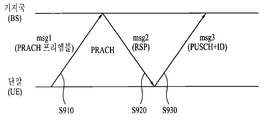
도 9는 단말과 기지국 간의 PRACH 절차를 예시적으로 나타낸 도면이다.9 is a diagram illustrating a PRACH procedure between a UE and a BS.
TA 그룹 1의 Pcell에서 동기를 확보하기 위해 기지국은 PDCCH를 통해 PDCCH 명령으로 PRACH를 트리거링 할 수 있다. 그러면 단말은 PRACH 프리엠블(msg1)을 기지국에 전송한다(S910). 단말이 초기에 동기를 맞추기 위한 PRACH 프리엠블 전송은 경쟁-기반 PRACH 프리엠블 전송이다. 기지국은 수신한 msg 1에 대한 응답으로서 랜덤 액세스 응답 메시지(msg 2)를 단말에 전송한다(S920). 여기서 msg 2에는 TA command를 포함하여 아래 표 7과 같은 내용이 포함되어 있다. 다음 표 7은 3GPP LTE TS 36.213에서 랜덤 액세스 응답 그랜트(RA response grant)에 포함된 정보를 나타낸다.In order to secure synchronization in the Pcell of the

한편, 도 8에서 단말이 TA 그룹 2의 Scell 2에서 상향링크/하향링크 동기를 맞추기 위해, 기지국은 PDCCH를 통해 PDCCH 명령으로 PRACH를 트리거링 할 수 있다. 그러면 단말은 PRACH 프리엠블(MSG1)을 기지국에 전송한다(S910). 단말이 비-경쟁 기반 PRACH 프리엠블(Non-contention based PRACH peamble)을 전송하기 때문에 기지국은 TA 용으로 PRACH가 필요하다. 단말의 TA 그룹 2의 Scell 2에서의 PRACH 프리엠블 전송은 비-경쟁 기반 PRACH 프리엠블 전송이다.Meanwhile, in FIG. 8, in order to align the uplink / downlink synchronization in the
본 발명에서는 서로 다른 TA 그룹을 지원하는 시스템에서 PCell을 포함하지 않는 TA 그룹에서의 비-경쟁 기반 PRACH 프리엠블 전송 프로세스는 msg1을 전송하는 것으로 프로세스를 종료하는 것을 제안한다. 즉 단말은 도 9에서 S910 단계만 수행하도록 제한할 수 있다. 이러헌 경우에서의 기지국의 PUSCH 자원 할당은 PDCCH를 통해서 전송하도록 한다. 또한, 초기(initial) TA command는 PDSCH 혹은 PDCCH에 포함되어 전송할 수 있다.In the present invention, the non-contention-based PRACH preamble transmission process in the TA group not including the PCell in the system supporting different TA groups proposes to terminate the process by transmitting msg1. In other words, the terminal can restrict to perform step S910 only in FIG. In this case, the PUSCH resource allocation of the base station is transmitted through the PDCCH. Also, an initial TA command can be included in the PDSCH or PDCCH and transmitted.
실시예Example 2(경쟁 기반 2 (Competitive based PRACHPRACH 프로시저에서의In the procedure 전력 제어) Power control)
단말이 서빙 셀 중 SCell에서 msg1(PRACH preamble)을 전송하면, 기지국은 msg2와 msg2에 의해 할당된 PUSCH에 대한 정보를 msg1을 전송한 셀(즉, Scell)이 아니라 다른 셀에서 전송할 수 있다. 이때, msg2가 전송되는 해당 셀을 지시해주는 지시자가 없거나 혹은 지시자가 가리키는 셀이 상향링크 동기가 맞춰져 있는 셀이라면(Pcell 및 Scell 모두 가능), 단말은 msg 2가 수신되는 해당 셀에 대한 축적 모드(accumulated mode)의 TPC command(PUSCH 또는 PUCCH를 위한 TPC command)를 리셋(reset)하도록 한다. 일 예로서, 단말이 Scell 2에서 전송한 msg1(PRACH preamble)에 대한 응답으로 기지국은 msg2를 msg1이 전송된 Scell 2에서 전송하든 다른 셀에서 전송하든, 단말은 msg2를 수신하면 msg1(PRACH preamble)을 전송한 Scell 2에 대한 축적 모드(accumulated mode)의 TPC command(PUSCH 또는 PUCCH를 위한 TPC command)를 리셋하여야 한다.If the UE transmits a msg 1 (PRACH preamble) in the SCell among the serving cells, the BS can transmit information on the PUSCH allocated by the
한편, 단말이 msg1(PRACH preamble)을 Scell 2에서 전송하고 기지국으로부터 msg2를 Scell 2가 아닌 다른 셀에서 수신한 경우, msg 2를 수신한 해당 셀과 페어링된 상향링크 셀(paired UL Cell)에서의 PUSCH/PUCCH 전력 제어는 축적 모드(accumulated mode)의 TPC command(PUSCH 또는 PUCCH를 위한 TPC command)는 리셋하지 않도록 한다. 그러나 이와 달리, msg 2를 수신한 해당 셀과 페어링된 상향링크 셀(paired UL Cell)에서 축적 모드의 TPC command(PUSCH 또는 PUCCH를 위한 TPC command)를 리셋할 수도 있다. 리셋은 0 dB 혹은 미리 정한 레벨로 적용할 수 있다. 미리 정한 레벨이 멀티 레벨일 경우 기지국에서 단말에 시그널링해 줄 수 있다.Meanwhile, when the MS transmits a msg 1 (PRACH preamble) in the
또한, 단말이 Scell에서 msg1(PRACH preamble)을 전송하고, 기지국으로부터 msg1에 대한 응답으로 Scell에서 msg2를 수신한 경우에, 해당 Scell에서는 축적 모드(accumulated mode)의 TPC command(PUSCH 또는 PUCCH를 위한 TPC command)는 리셋하도록 하고, 그러나 다른 셀(Pcell 및 다른 Scell)에 대해서는 축적 모드(accumulated mode)의 TPC command(PUSCH 또는 PUCCH를 위한 TPC command)는 리셋하지 않을 수 있다.Also, when the UE transmits a msg 1 (PRACH preamble) in the Scell and receives msg2 from the Scell in response to the
또한, 단말이 msg2(랜덤 액세스 응답 메시지)를 Scell에서 수신하지 않고 ![]()
![]()
![]()
![]()
한편, PUCCH에 대한 전력 제어 있어서, Pcell에서의 랜덤 액세스 동작은 다른 TA 그룹에서의 랜덤 액세스 동작에 영향을 받지 않는다. 즉, ![]()
![]()
![]()
![]()
![]()
![]()
![]()
![]()
![]()
![]()
실시예Example 3 3
기지국이 전송하는 msg2의 정보에는 단말이 msg1을 전송한 셀에 대한 TA(Timing Advance) command 값과 PUSCH grant에 대한 정보와 상향링크 딜레이(UL delay), CSI 요청에 대한 정보가 포함될 수 있다. 따라서, msg2에 의해 스케줄링된 PUSCH가 msg1을 전송한 셀에서 전송되지 않을 경우 상기 msg2에서 TA(Timing Advance) command에 대한 셀 인덱스 정보가 포함되어야 하고, PUSCH grant가 적용될 셀에 대한 인덱스 정보가 각기 설정되어야 한다. msg2에 의한 PUSCH가 msg1을 전송한 셀에 적용되지 않을 경우에는 msg1을 전송한 셀의 PUSCH 전력 제어 파라미터 중 f(i)= ![]()
![]()
![]()
![]()
실시예Example 4 4
랜덤 액세스 응답 grant(msg2)에 의해 할당된 PUSCH를 j=2로 정의하고 이때의 전력 제어 수식 중 ![]()
![]()
![]()
![]()
비-경쟁 기반 랜덤 액세스 절차에서는 기지국이 msg3를 전송하지 않고 normal PUSCH를 전송한다. 따라서, 이때의 PUSCH의 전력 제어는 PUSCH 전력 제어를 따르도록 한다. 즉 ![]()
![]()
![]()
![]()
![]()
![]()
![]()
![]()
![]()
![]()
![]()
![]()
![]()
![]()
동적 스케줄링되는 grant에 대응하는 PUSCH 전송/재전송은 j=1이고, 랜덤 액세스 응답 grant에 대응하는 PUSCH 전송/재전송은 j=2이다. 그리고, ![]()
![]()
![]()
![]()
![]()
![]()
상술한 본 발명에 따른 실시예들은 TA 그룹이 두 개 이상 지원되는 시스템에서도 확장 적용 가능하다. 그리고, 멀티플 TA(Multiple timing advance)가 적용되는 시스템에서도 단말은 효율적으로 전송 파워를 설정할 수 있게 된다.The embodiments of the present invention described above can be extended even in a system in which two or more TA groups are supported. Also, in a system in which multiple timing advance is applied, the UE can efficiently set the transmission power.
이상에서 설명된 실시예들은 본 발명의 구성요소들과 특징들이 소정 형태로 결합된 것들이다. 각 구성요소 또는 특징은 별도의 명시적 언급이 없는 한 선택적인 것으로 고려되어야 한다. 각 구성요소 또는 특징은 다른 구성요소나 특징과 결합되지 않은 형태로 실시될 수 있다. 또한, 일부 구성요소들 및/또는 특징들을 결합하여 본 발명의 실시예를 구성하는 것도 가능하다. 본 발명의 실시예들에서 설명되는 동작들의 순서는 변경될 수 있다. 어느 실시예의 일부 구성이나 특징은 다른 실시예에 포함될 수 있고, 또는 다른 실시예의 대응하는 구성 또는 특징과 교체될 수 있다. 특허청구범위에서 명시적인 인용 관계가 있지 않은 청구항들을 결합하여 실시예를 구성하거나 출원 후의 보정에 의해 새로운 청구항으로 포함시킬 수 있음은 자명하다.The embodiments described above are those in which the elements and features of the present invention are combined in a predetermined form. Each component or feature shall be considered optional unless otherwise expressly stated. Each component or feature may be implemented in a form that is not combined with other components or features. It is also possible to construct embodiments of the present invention by combining some of the elements and / or features. The order of the operations described in the embodiments of the present invention may be changed. Some configurations or features of certain embodiments may be included in other embodiments, or may be replaced with corresponding configurations or features of other embodiments. It is clear that the claims that are not expressly cited in the claims may be combined to form an embodiment or be included in a new claim by an amendment after the application.
본 발명은 본 발명의 정신 및 필수적 특징을 벗어나지 않는 범위에서 다른 특정한 형태로 구체화될 수 있음은 당업자에게 자명하다. 따라서, 상기의 상세한 설명은 모든 면에서 제한적으로 해석되어서는 아니되고 예시적인 것으로 고려되어야 한다. 본 발명의 범위는 첨부된 청구항의 합리적 해석에 의해 결정되어야 하고, 본 발명의 등가적 범위 내에서의 모든 변경은 본 발명의 범위에 포함된다.It will be apparent to those skilled in the art that the present invention may be embodied in other specific forms without departing from the spirit or essential characteristics thereof. Accordingly, the above description should not be construed in a limiting sense in all respects and should be considered illustrative. The scope of the present invention should be determined by rational interpretation of the appended claims, and all changes within the scope of equivalents of the present invention are included in the scope of the present invention.
무선통신 시스템에서 단말이 상향링크 전송 전력을 설정하는 방법은 3GPP LTE, LTE-A 시스템 등 다양한 이동통신 시스템에 산업적으로 적용이 가능하다.In the wireless communication system, a method for setting uplink transmission power of a terminal can be industrially applied to various mobile communication systems such as 3GPP LTE and LTE-A systems.
Claims (14)
기지국으로부터 복수의 서빙 셀들을 설정받는 단계;
상기 설정된 복수의 서빙 셀 중 세컨더리 셀(Secondary cell, Scell)에서 랜덤 액세스 프리앰블을 포함하는 랜덤 액세스 메시지를 상기 기지국으로 전송하는 단계;
상기 랜덤 액세스 메시지에 대한 응답으로 상기 기지국으로부터 랜덤 액세스 응답 메시지를 수신하는 단계; 및
상기 랜덤 액세스 응답 메시지 수신함에 따라 상기 랜덤 액세스 메시지를 전송한 상기 Scell에서의 현재의 상향링크 전송 제어 조정 상태를 나타내는 축적 모드(accumulated mode)의 인자값을 리셋하여 설정하는 단계를 포함하는, 상향링크 전송 전력 설정 방법.A method for setting uplink transmission power in a wireless communication system,
Receiving a plurality of serving cells from a base station;
Transmitting a random access message including a random access preamble from a secondary cell (Scell) among the plurality of serving cells to the base station;
Receiving a random access response message from the base station in response to the random access message; And
And resetting and setting an argument value of an accumulated mode indicating a current uplink transmission control adjustment state in the Scell that transmitted the random access message according to the random access response message reception. How to set transmit power.
상기 인자 값은 PUSCH(Physical Uplink Shared CHannel) 또는 PUCCH(Physical Uplink Control CHannel)에 대한 값인, 상향링크 전송 전력 설정 방법.The method according to claim 1,
Wherein the factor is a value for a PUSCH (Physical Uplink Shared CHannel) or a PUCCH (Physical Uplink Control CHannel).
상기 랜덤 액세스 응답 메시지는 전송 전력 제어 명령(TPC command) 값을 포함하며,
상기 인자 값이 리셋되는 경우, 상기 인자 값의 초기 값은 상기 랜덤 액세스 응답 메시지에 포함된 상기 TPC command 값과 상기 Scell에서 적어도 1회 이상 랜덤 액세스 프리엠블을 전송에 따른 총 전력 램프-업(ramp-up)값을 이용하여 설정되는, 상향링크 전송 전력 설정 방법.3. The method of claim 2,
Wherein the random access response message comprises a transmit power control (TPC) command value,
If the factor value is reset, the initial value of the factor value is calculated based on the TPC command value included in the random access response message and a total power ramp-up (ramp) value according to transmission of the random access preamble at least once in the Scell -up) value of the uplink transmission power.
상기 랜덤 액세스 응답 메시지가 상기 복수의 서빙 셀 중 상기 Scell을 제외한 나머지 어느 한 셀에서 수신되고, 상기 기지국으로부터 상기 PUSCH 또는 상기 PUCCH와 관련된 단말-특정한 콤포넌트 계수값을 시그널링받는 경우, 상기 인자 값은 0으로 리셋되어 설정되는, 상향링크 전송 전력 설정 방법.3. The method of claim 2,
When the random access response message is received from any one of the plurality of serving cells except for the Scell and the UE-specific component count value related to the PUSCH or the PUCCH is signaled from the base station, the factor value is set to 0 And setting up the uplink transmission power.
상기 설정된 인자 값의 초기값을 이용하여 상기 PUSCH 또는 상기 PUCCH를 전송하기 위한 상향링크 전송 전력을 결정하는 단계; 및
상기 결정된 상향링크 전송 전력으로 상기 PUSCH 또는 상기 PUCCH를 전송하는 단계를 더 포함하는, 상향링크 전송 전력 설정 방법.The method of claim 3,
Determining an uplink transmission power for transmitting the PUSCH or the PUCCH using an initial value of the set factor; And
And transmitting the PUSCH or the PUCCH with the determined uplink transmission power.
상기 설정된 복수의 서빙 셀 중 상기 Scell을 제외한 나머지 셀에 대해서는 상기 인자값을 리셋하지 않는 것을 특징으로 하는, 상향링크 전송 전력 설정 방법.The method according to claim 1,
And does not reset the factor value for cells other than the Scell among the set plurality of serving cells.
상기 Scell은 제 1 타이밍 어드밴스(Timing Advance, TA) 그룹에 속하고 상기 나머지 셀은 제 2 TA 그룹에 속하는, 상향링크 전송 전력 설정 방법.The method according to claim 6,
Wherein the Scell belongs to a first Timing Advance (TA) group and the remaining cells belong to a second TA group.
상기 나머지 셀은 상향링크 동기가 맞추어진 셀인, 상향링크 전송 전력 설정 방법.The method according to claim 6,
And the remaining cells are cells to which uplink synchronization is applied.
상기 제 2 TA 그룹은 프라이머리 셀(Primary cell, Pcell)을 포함하는, 상향링크 전송 전력 설정 방법.8. The method of claim 7,
And the second TA group includes a primary cell (Pcell).
기지국으로부터 설정된 복수의 서빙 셀들에 대한 정보를 수신하도록 구성된 수신기와,
상기 설정된 복수의 서빙 셀 중 세컨더리 셀(Secondary cell, Scell)에서 랜덤 액세스 프리앰블을 포함하는 랜덤 액세스 메시지를 상기 기지국으로 전송하도록 구성된 송신기를 포함하고,
상기 수신기는 상기 랜덤 액세스 메시지에 대한 응답으로 상기 기지국으로부터 랜덤 액세스 응답 메시지를 수신하도록 더 구성되며,
상기 랜덤 액세스 응답 메시지 수신함에 따라 상기 랜덤 액세스 메시지를 전송한 상기 Scell에서의 현재의 상향링크 전송 제어 조정 상태를 나타내는 축적 모드(accumulated mode)의 인자값을 리셋하여 설정하는 프로세서를 더 포함하는, 단말.An apparatus for setting uplink transmission power in a wireless communication system,
A receiver configured to receive information about a plurality of serving cells set up from a base station,
And a transmitter configured to transmit, to the base station, a random access message including a random access preamble in a secondary cell (Scell) among the set plurality of serving cells,
Wherein the receiver is further configured to receive a random access response message from the base station in response to the random access message,
Further comprising a processor for resetting and setting an argument value of an accumulated mode indicating a current uplink transmission control adjustment state in the Scell that transmitted the random access message according to the random access response message received, .
상기 프로세서는 상기 설정된 복수의 서빙 셀 중 상기 Scell을 제외한 나머지 셀에 대해서는 상기 인자값을 리셋하지 않도록 구성된 것을 특징으로 하는, 단말.11. The method of claim 10,
Wherein the processor is configured not to reset the factor value for cells other than the scell among the set plurality of serving cells.
상기 Scell은 제 1 타이밍 어드밴스(Timing Advance, TA) 그룹에 속하고 상기 나머지 셀은 제 2 TA 그룹에 속하는, 단말.12. The method of claim 11,
Wherein the Scell belongs to a first Timing Advance (TA) group and the remaining cells belong to a second TA group.
상기 나머지 셀은 상향링크 동기가 맞추어진 셀인, 단말.12. The method of claim 11,
Wherein the remaining cells are cells whose uplink synchronization is adapted.
상기 제 2 TA 그룹은 프라이머리 셀(Primary cell, Pcell)을 포함하는, 단말.13. The method of claim 12,
Wherein the second TA group comprises a primary cell (Pcell).
Applications Claiming Priority (3)
| Application Number | Priority Date | Filing Date | Title |
|---|---|---|---|
| US201161557389P | 2011-11-08 | 2011-11-08 | |
| US61/557,389 | 2011-11-08 | ||
| PCT/KR2012/009415 WO2013069994A1 (en) | 2011-11-08 | 2012-11-08 | Method and device for setting uplink transmission power in wireless communication system |
Publications (1)
| Publication Number | Publication Date |
|---|---|
| KR20140097321A true KR20140097321A (en) | 2014-08-06 |
Family
ID=48290291
Family Applications (1)
| Application Number | Title | Priority Date | Filing Date |
|---|---|---|---|
| KR1020147015446A KR20140097321A (en) | 2011-11-08 | 2012-11-08 | Method and device for setting uplink transmission power in wireless communication system |
Country Status (6)
| Country | Link |
|---|---|
| US (1) | US20140321442A1 (en) |
| EP (1) | EP2779759A4 (en) |
| JP (1) | JP6047171B2 (en) |
| KR (1) | KR20140097321A (en) |
| CN (1) | CN104041149B (en) |
| WO (1) | WO2013069994A1 (en) |
Cited By (1)
| Publication number | Priority date | Publication date | Assignee | Title |
|---|---|---|---|---|
| KR20220093265A (en) * | 2017-04-21 | 2022-07-05 | 삼성전자주식회사 | Information type multiplexing and power control |
Families Citing this family (57)
| Publication number | Priority date | Publication date | Assignee | Title |
|---|---|---|---|---|
| US20140112276A1 (en) * | 2011-04-28 | 2014-04-24 | Lg Electronics Inc. | Method and apparatus for performing a random access process |
| KR20140044361A (en) * | 2011-07-11 | 2014-04-14 | 엘지전자 주식회사 | Method and apparatus for performing random access in wireless communication system |
| US8395985B2 (en) | 2011-07-25 | 2013-03-12 | Ofinno Technologies, Llc | Time alignment in multicarrier OFDM network |
| CN105101385B (en) * | 2011-08-30 | 2018-10-19 | 华为技术有限公司 | A kind of Poewr control method, activation management method, user terminal and base station |
| EP2774426B1 (en) | 2011-11-04 | 2019-01-02 | Interdigital Patent Holdings, Inc. | Method and apparatus for power control for wireless transmissions on multiple component carriers associated with multiple timing advances |
| CN103188061B (en) * | 2011-12-31 | 2017-11-03 | 中兴通讯股份有限公司 | The sending method and device of hybrid automatic repeat-request response message |
| EP3937551A3 (en) | 2012-01-25 | 2022-02-09 | Comcast Cable Communications, LLC | Random access channel in multicarrier wireless communications with timing advance groups |
| US9237537B2 (en) | 2012-01-25 | 2016-01-12 | Ofinno Technologies, Llc | Random access process in a multicarrier base station and wireless device |
| US8897248B2 (en) | 2012-01-25 | 2014-11-25 | Ofinno Technologies, Llc | Multicarrier signal transmission in wireless communications |
| US8964683B2 (en) | 2012-04-20 | 2015-02-24 | Ofinno Technologies, Llc | Sounding signal in a multicarrier wireless device |
| US20130259008A1 (en) | 2012-04-01 | 2013-10-03 | Esmael Hejazi Dinan | Random Access Response Process in a Wireless Communications |
| US9215678B2 (en) | 2012-04-01 | 2015-12-15 | Ofinno Technologies, Llc | Timing advance timer configuration in a wireless device and a base station |
| US11943813B2 (en) | 2012-04-01 | 2024-03-26 | Comcast Cable Communications, Llc | Cell grouping for wireless communications |
| US8958342B2 (en) | 2012-04-17 | 2015-02-17 | Ofinno Technologies, Llc | Uplink transmission power in a multicarrier wireless device |
| US11582704B2 (en) | 2012-04-16 | 2023-02-14 | Comcast Cable Communications, Llc | Signal transmission power adjustment in a wireless device |
| US11252679B2 (en) | 2012-04-16 | 2022-02-15 | Comcast Cable Communications, Llc | Signal transmission power adjustment in a wireless device |
| US11825419B2 (en) | 2012-04-16 | 2023-11-21 | Comcast Cable Communications, Llc | Cell timing in a wireless device and base station |
| EP3337079A1 (en) | 2012-04-16 | 2018-06-20 | Comcast Cable Communications, LLC | Cell group configuration for uplink transmission in a multicarrier wireless device and base station with timing advance groups |
| US8964593B2 (en) | 2012-04-16 | 2015-02-24 | Ofinno Technologies, Llc | Wireless device transmission power |
| US9179425B2 (en) | 2012-04-17 | 2015-11-03 | Ofinno Technologies, Llc | Transmit power control in multicarrier communications |
| US9107206B2 (en) | 2012-06-18 | 2015-08-11 | Ofinne Technologies, LLC | Carrier grouping in multicarrier wireless networks |
| US9084228B2 (en) | 2012-06-20 | 2015-07-14 | Ofinno Technologies, Llc | Automobile communication device |
| US11622372B2 (en) | 2012-06-18 | 2023-04-04 | Comcast Cable Communications, Llc | Communication device |
| US11882560B2 (en) | 2012-06-18 | 2024-01-23 | Comcast Cable Communications, Llc | Carrier grouping in multicarrier wireless networks |
| US8971298B2 (en) | 2012-06-18 | 2015-03-03 | Ofinno Technologies, Llc | Wireless device connection to an application server |
| US9113387B2 (en) | 2012-06-20 | 2015-08-18 | Ofinno Technologies, Llc | Handover signalling in wireless networks |
| US9210619B2 (en) | 2012-06-20 | 2015-12-08 | Ofinno Technologies, Llc | Signalling mechanisms for wireless device handover |
| US9179457B2 (en) | 2012-06-20 | 2015-11-03 | Ofinno Technologies, Llc | Carrier configuration in wireless networks |
| US10172121B2 (en) * | 2013-07-12 | 2019-01-01 | Sharp Kabushiki Kaisha | Terminal device, method, and integrated circuit |
| WO2015056991A1 (en) * | 2013-10-18 | 2015-04-23 | 삼성전자 주식회사 | Method and apparatus for controlling uplink random access procedure in mobile communication system |
| KR102159391B1 (en) | 2013-10-18 | 2020-09-23 | 삼성전자주식회사 | Method and Apparatus for controlling uplink random access procedure in a mobile communication system |
| CN104754742B (en) * | 2013-12-25 | 2019-02-05 | 中国移动通信集团公司 | A kind of resource allocation methods and device |
| US9854576B2 (en) * | 2013-12-27 | 2017-12-26 | Sharp Kabushiki Kaisha | Terminal device, base station apparatus, and method |
| WO2015137632A1 (en) * | 2014-03-11 | 2015-09-17 | Lg Electronics Inc. | Method for allocating temporary identifier to terminal in random access procedure in wireless communication system and apparatus tehrefor |
| US9967828B2 (en) | 2014-04-24 | 2018-05-08 | Lg Electronics Inc. | Method and apparatus for deciding maximum uplink transmission power in wireless communication system |
| US9974028B2 (en) * | 2014-04-30 | 2018-05-15 | Sharp Kabushiki Kaisha | Terminal device, base station device and method |
| MX361265B (en) | 2014-05-09 | 2018-12-03 | Lg Electronics Inc | Method for transmitting synchronization signal for direct communication between terminals in wireless communication system, and apparatus therefor. |
| US20170171825A1 (en) * | 2014-07-11 | 2017-06-15 | Ntt Docomo, Inc. | User terminal and radio communication method |
| WO2016085287A1 (en) * | 2014-11-27 | 2016-06-02 | 엘지전자 주식회사 | Random access method and apparatus therefor |
| US9871572B2 (en) | 2015-03-09 | 2018-01-16 | Ofinno Technologies, Llc | Uplink control channel in a wireless network |
| US10182426B2 (en) * | 2015-03-13 | 2019-01-15 | Qualcomm Incorporated | Scheduling of downlink transmissions based on exchanges of pre-scheduling and scheduling messages |
| US10231259B2 (en) * | 2015-03-14 | 2019-03-12 | Qualcomm Incorporated | Control signaling supporting multi-priority scheduling |
| US10595302B2 (en) | 2015-03-15 | 2020-03-17 | Qualcomm Incorporated | Subframe structure with embedded control signaling |
| US10117187B2 (en) | 2015-06-20 | 2018-10-30 | Ofinno Technologies, Llc | Initializing uplink power in a wireless network |
| JP6642842B2 (en) * | 2015-08-14 | 2020-02-12 | ホアウェイ・テクノロジーズ・カンパニー・リミテッド | Information transmission method, base station, and user equipment |
| DE112015006893T5 (en) * | 2015-09-10 | 2018-05-24 | Intel IP Corporation | Evolved Node-B (eNB), user equipment (UE) and flexible duplex communication techniques |
| JP2019110351A (en) * | 2016-04-20 | 2019-07-04 | シャープ株式会社 | Terminal device, base station device, communication method, and integrated circuit |
| US10367677B2 (en) | 2016-05-13 | 2019-07-30 | Telefonaktiebolaget Lm Ericsson (Publ) | Network architecture, methods, and devices for a wireless communications network |
| US10630410B2 (en) | 2016-05-13 | 2020-04-21 | Telefonaktiebolaget Lm Ericsson (Publ) | Network architecture, methods, and devices for a wireless communications network |
| CN108809600B (en) * | 2017-05-05 | 2023-11-21 | 华为技术有限公司 | Communication method, system and related equipment |
| US10813140B2 (en) * | 2018-04-02 | 2020-10-20 | Lg Electronics Inc. | Method and apparatus for transmitting and receiving random access preambles in a wireless communication system |
| US11706812B2 (en) | 2018-07-04 | 2023-07-18 | Lg Electronics Inc. | Method for performing uplink transmission in wireless communication system, and device therefor |
| US11212843B2 (en) * | 2018-08-08 | 2021-12-28 | Lenovo (Singapore) Pte. Ltd. | Skipping uplink transmission allocated by RACH procedure |
| WO2021010709A1 (en) * | 2019-07-12 | 2021-01-21 | 엘지전자 주식회사 | Method for transmitting or receiving uplink channel in wireless communication system, and device therefor |
| CN114040512B (en) * | 2021-11-23 | 2023-07-25 | 新华三技术有限公司 | Random access method and device |
| CN114402655B (en) * | 2021-12-17 | 2024-03-05 | 北京小米移动软件有限公司 | Method and device for determining position information |
| WO2024009196A1 (en) * | 2022-07-04 | 2024-01-11 | Telefonaktiebolaget Lm Ericsson (Publ) | User equipment interpretation of transmit power control (tpc) and timing advance command (tac) in random access response (rar) for multiple physical random access channel (prach) transmissions |
Family Cites Families (9)
| Publication number | Priority date | Publication date | Assignee | Title |
|---|---|---|---|---|
| US8228855B2 (en) * | 2008-03-24 | 2012-07-24 | Qualcomm Incorporated | Uplink power headroom definition for E-DCH in CELL—FACH |
| JP5085481B2 (en) * | 2008-09-22 | 2012-11-28 | 株式会社エヌ・ティ・ティ・ドコモ | Transmission power control method, mobile communication system, and radio base station |
| BR112012012086A2 (en) * | 2009-11-19 | 2017-10-03 | Interdigital Patent Holdings Inc | ENABLING/DISABLEING COMPONENT CARRIERS IN SYSTEMS WITH MULTIPLE CARRIERS |
| KR20110102233A (en) * | 2010-03-08 | 2011-09-16 | 엘지전자 주식회사 | Apparatus and method for controlling uplink transmit power |
| CN102036411B (en) * | 2010-12-02 | 2013-06-26 | 大唐移动通信设备有限公司 | Method and device for random access |
| CN102118801B (en) * | 2011-03-31 | 2013-07-24 | 电信科学技术研究院 | Method and device for unlink transmission in multicarrier aggregation system |
| US20120282970A1 (en) * | 2011-05-03 | 2012-11-08 | Renesas Mobile Corporation | Uplink transmission power control mechanism |
| JP5331161B2 (en) * | 2011-05-19 | 2013-10-30 | シャープ株式会社 | Wireless communication system, base station apparatus, mobile station apparatus, wireless communication method, and integrated circuit |
| US20130010711A1 (en) * | 2011-07-06 | 2013-01-10 | Daniel Larsson | Random Access with Primary and Secondary Component Carrier Communications |
-
2012
- 2012-11-08 EP EP12847130.7A patent/EP2779759A4/en not_active Ceased
- 2012-11-08 KR KR1020147015446A patent/KR20140097321A/en not_active Application Discontinuation
- 2012-11-08 US US14/355,518 patent/US20140321442A1/en not_active Abandoned
- 2012-11-08 JP JP2014540948A patent/JP6047171B2/en not_active Expired - Fee Related
- 2012-11-08 WO PCT/KR2012/009415 patent/WO2013069994A1/en active Application Filing
- 2012-11-08 CN CN201280066445.9A patent/CN104041149B/en not_active Expired - Fee Related
Cited By (1)
| Publication number | Priority date | Publication date | Assignee | Title |
|---|---|---|---|---|
| KR20220093265A (en) * | 2017-04-21 | 2022-07-05 | 삼성전자주식회사 | Information type multiplexing and power control |
Also Published As
| Publication number | Publication date |
|---|---|
| EP2779759A1 (en) | 2014-09-17 |
| EP2779759A4 (en) | 2015-04-22 |
| JP2015502068A (en) | 2015-01-19 |
| CN104041149B (en) | 2018-02-23 |
| CN104041149A (en) | 2014-09-10 |
| US20140321442A1 (en) | 2014-10-30 |
| WO2013069994A1 (en) | 2013-05-16 |
| JP6047171B2 (en) | 2016-12-21 |
Similar Documents
| Publication | Publication Date | Title |
|---|---|---|
| JP6047171B2 (en) | Method and apparatus for setting uplink transmission power in a wireless communication system | |
| KR101878145B1 (en) | Method for transmitting control information and device for same | |
| KR102544449B1 (en) | Method and apparatus for transceiving wireless signal in wirelesscommunication system | |
| US9848411B2 (en) | Method for transmitting uplink control channel by terminal in wireless communication system | |
| US9532344B2 (en) | Method for controlling uplink power in wireless communication system and device therefor | |
| US10333739B2 (en) | Method for transmitting or receiving signal in wireless communication system supporting D2D communication and apparatus for performing same | |
| KR102322507B1 (en) | Transmission power control method for sounding reference signal in wireless communication system and apparatus therefor | |
| KR20180032574A (en) | Method for channel access in a wireless communication system and apparatus for performing the same | |
| US20150296509A1 (en) | Method for transceiving control signal, and apparatus therefor | |
| US20150271758A1 (en) | Method and apparatus for controlling tpc command timing considering tdd-fdd carrier aggregation | |
| US10484142B2 (en) | Method for transmitting HARQ ACK/NACK feedback by using terminal-specific TDD frame in wireless communication system, and device therefor | |
| KR20140084133A (en) | Method for transmitting power headroom report, and apparatus for same | |
| US9491717B2 (en) | Method for determining uplink transmission power in a network including a plurality of cells, and apparatus therefor | |
| KR20130118878A (en) | Method for transmitting control information and device therefor | |
| US10194422B2 (en) | Signal transmission and reception method in wireless communication system supporting carrier aggregation, and device for same | |
| US20140192687A1 (en) | Method and apparatus for transmitting uplink control information in a wireless communication system | |
| WO2012157967A2 (en) | Method for controlling uplink transmission power by a terminal that adopts a time division duplex (tdd) scheme in a wireless communication system, and terminal device thereof |
Legal Events
| Date | Code | Title | Description |
|---|---|---|---|
| WITN | Application deemed withdrawn, e.g. because no request for examination was filed or no examination fee was paid |