KR20140088084A - Transfer device for transferring sealed packages of a pourable food product and method of removing fallen sealed packages from the transfer device - Google Patents
Transfer device for transferring sealed packages of a pourable food product and method of removing fallen sealed packages from the transfer device Download PDFInfo
- Publication number
- KR20140088084A KR20140088084A KR1020147008852A KR20147008852A KR20140088084A KR 20140088084 A KR20140088084 A KR 20140088084A KR 1020147008852 A KR1020147008852 A KR 1020147008852A KR 20147008852 A KR20147008852 A KR 20147008852A KR 20140088084 A KR20140088084 A KR 20140088084A
- Authority
- KR
- South Korea
- Prior art keywords
- package
- axis
- respect
- opening
- conveying
- Prior art date
Links
Images
Classifications
-
- B—PERFORMING OPERATIONS; TRANSPORTING
- B65—CONVEYING; PACKING; STORING; HANDLING THIN OR FILAMENTARY MATERIAL
- B65G—TRANSPORT OR STORAGE DEVICES, e.g. CONVEYORS FOR LOADING OR TIPPING, SHOP CONVEYOR SYSTEMS OR PNEUMATIC TUBE CONVEYORS
- B65G47/00—Article or material-handling devices associated with conveyors; Methods employing such devices
- B65G47/34—Devices for discharging articles or materials from conveyor
- B65G47/46—Devices for discharging articles or materials from conveyor and distributing, e.g. automatically, to desired points
-
- B—PERFORMING OPERATIONS; TRANSPORTING
- B65—CONVEYING; PACKING; STORING; HANDLING THIN OR FILAMENTARY MATERIAL
- B65B—MACHINES, APPARATUS OR DEVICES FOR, OR METHODS OF, PACKAGING ARTICLES OR MATERIALS; UNPACKING
- B65B65/00—Details peculiar to packaging machines and not otherwise provided for; Arrangements of such details
-
- B—PERFORMING OPERATIONS; TRANSPORTING
- B65—CONVEYING; PACKING; STORING; HANDLING THIN OR FILAMENTARY MATERIAL
- B65G—TRANSPORT OR STORAGE DEVICES, e.g. CONVEYORS FOR LOADING OR TIPPING, SHOP CONVEYOR SYSTEMS OR PNEUMATIC TUBE CONVEYORS
- B65G21/00—Supporting or protective framework or housings for endless load-carriers or traction elements of belt or chain conveyors
- B65G21/20—Means incorporated in, or attached to, framework or housings for guiding load-carriers, traction elements or loads supported on moving surfaces
- B65G21/2045—Mechanical means for guiding or retaining the load on the load-carrying surface
- B65G21/2063—Mechanical means for guiding or retaining the load on the load-carrying surface comprising elements not movable in the direction of load-transport
- B65G21/2072—Laterial guidance means
-
- B—PERFORMING OPERATIONS; TRANSPORTING
- B65—CONVEYING; PACKING; STORING; HANDLING THIN OR FILAMENTARY MATERIAL
- B65B—MACHINES, APPARATUS OR DEVICES FOR, OR METHODS OF, PACKAGING ARTICLES OR MATERIALS; UNPACKING
- B65B61/00—Auxiliary devices, not otherwise provided for, for operating on sheets, blanks, webs, binding material, containers or packages
- B65B61/28—Auxiliary devices, not otherwise provided for, for operating on sheets, blanks, webs, binding material, containers or packages for discharging completed packages from machines
-
- B—PERFORMING OPERATIONS; TRANSPORTING
- B65—CONVEYING; PACKING; STORING; HANDLING THIN OR FILAMENTARY MATERIAL
- B65G—TRANSPORT OR STORAGE DEVICES, e.g. CONVEYORS FOR LOADING OR TIPPING, SHOP CONVEYOR SYSTEMS OR PNEUMATIC TUBE CONVEYORS
- B65G47/00—Article or material-handling devices associated with conveyors; Methods employing such devices
- B65G47/22—Devices influencing the relative position or the attitude of articles during transit by conveyors
- B65G47/24—Devices influencing the relative position or the attitude of articles during transit by conveyors orientating the articles
- B65G47/256—Devices influencing the relative position or the attitude of articles during transit by conveyors orientating the articles removing incorrectly orientated articles
Abstract
쏟을 수 있는 식품 생산품의 밀봉된 패키지(2)를 이송하기 위한 이송 장치(1)로서, 적어도 부분적으로 만곡된 경로(P)를 따라 상기 패키지(2)를 반송하기 위한 운반하는 수단(5)을 포함하여 구성되고; 상기 경로(P)의 하나의 측면 상에 배열되고, 사용 시, 상기 경로(P)를 따라 추락한 패키지(2)의 배출을 허용하도록 적용된 관통 개구(20)를 포함하여 구성되는 것을 특징으로 하는 이송 장치가 개시된다.A conveying device (1) for conveying a sealed package (2) of a pourable food product, characterized in that it comprises means (5) for conveying said package (2) along at least partly curved path ≪ / RTI > And a through opening (20) arranged on one side of the path (P) and adapted to permit, in use, the evacuation of the package (2) that has fallen along the path (P) A transfer device is started.

Description
본 발명은 쏟을 수 있는 식품 생산품의 밀봉된 패키지를 이송하기 위한 이송 장치에 관한 것이다. The present invention relates to a transfer device for transferring a sealed package of a pourable food product.
또한, 본 발명은 이송 장치로부터 쏟을 수 있는 식품 생산품의 추락한 밀봉된 패키지를 제거하기 위한 방법에 관한 것이다. The present invention also relates to a method for removing a fallen sealed package of a food product that may be poured from a transfer device.
공지된 바와 같이, 과일 주스, 저온 살균(pasteurized) 또는 UHT(ultra-high-temperature treated) 밀크, 와인, 토마토 소스 등과 같은 많은 식품 생산품들이 살균된 포장 재료로 만들어진 패키지로 판매되고 있다.As is well known, many food products such as fruit juice, pasteurized or ultra-high-temperature treated (UHT) milk, wine, tomato sauce, and the like are sold in packages made of sterilized packaging materials.
전형적인 예의 이 타입의 패키지는, Tetra Brik Aseptic(등록 상표)로 공지된 액체 또는 쏟을 수 있는 식품 생산품을 위한 직육면체-형상의 패키지인데, 이는 라미네이트된(적층된) 스트립 포장 재료를 접고 밀봉함으로써 만들어진다. A package of this type of typical example is a rectangular parallelepiped-shaped package for liquid or pourable food products known as Tetra Brik Aseptic (R), which is made by folding and sealing laminated (laminated) strip packaging material.
포장 재료는, 예를 들어 종이인 섬유 재료, 또는 미네랄-충전된 폴리프로필렌 재료의 층을 포함하여 구성될 수 있는, 강성 및 강도를 위한 베이스 층 및; 베이스 층의 양쪽 측면을 덮는, 예를 들어 폴리에틸렌 필름인 가열-밀봉 플라스틱 재료의 다수의 층을 실질적으로 포함하여 구성되는 다층 구조를 갖는다. The packaging material may comprise a base layer for stiffness and strength, which may comprise, for example, a fiber material that is paper or a layer of mineral-filled polypropylene material; Layered structure consisting essentially of a plurality of layers of heat-seal plastic material, for example a polyethylene film, covering both sides of the base layer.
UHT 밀크와 같은 장기 저장 생산품을 위한 무균성 패키지의 경우, 포장 재료는 가스- 및 광-장벽 재료의 층, 예를 들어 알루미늄 호일 또는 에틸렌 비닐 알콜(EVOH) 호일을 포함하여 구성되며, 이 층은 가열-밀봉 플라스틱 재료의 층 상에 겹치고, 차례로 식품 생산품과 결국 접촉하는 패키지의 내부 페이스를 형성하는 가열-밀봉 플라스틱 재료의 다른 층으로 덮인다. In the case of aseptic packages for long term storage products such as UHT milks, the packaging material comprises a layer of gas- and photo-barrier material, for example an aluminum foil or an ethylene vinyl alcohol (EVOH) foil, Is covered with another layer of heat-sealing plastic material that overlies the layer of heat-seal plastic material and in turn forms the internal face of the package in contact with the food product.
공지된 바와 같이, 이 종류의 패키지는 완전히 자동인 포장 머신 상에서 생산되는데, 그 머신 상에서 튜브가 웹-공급 포장 재료로부터 연속적으로 형성되고; 포장 재료의 웹은, 예를 들어 과산화수소 용액과 같은 화학적 살균제를 적용함으로써 포장 머신 상에서 살균되고, 이 과산화수소는 살균이 완료되면, 포장 재료의 표면으로부터, 예를 들어 가열에 의해 증발되어 제거된다. 이렇게 살균된 포장 재료의 웹은 폐쇄된, 살균 환경 내에 유지되고, 길이방향으로 접히고 밀봉되어, 수직의 튜브를 형성한다. As is known, this kind of package is produced on a fully automatic packaging machine on which tubes are continuously formed from a web-fed packaging material; The web of packaging material is sterilized on the packaging machine by applying a chemical sterilizing agent such as, for example, hydrogen peroxide solution, which is evaporated off from the surface of the packaging material, for example by heating, once sterilization is complete. The web of sterilized packaging material is held in a closed, sterile environment, folded longitudinally and sealed to form a vertical tube.
튜브는 살균된 또는 저온 살균된(pasteurized) 식품 생산품으로 연속적으로 아래쪽으로 충전되고, 밀봉된 후, 균등하게 이격된 단면을 따라서 절단되어 배게형 팩(pillow pack)을 형성하며, 접는 유닛으로 공급되어 완성된 패키지를 형성할 수 있다.The tube is continuously filled down to a sterilized or pasteurized food product, sealed, cut along an evenly spaced section to form a pillow pack, and fed into a folding unit A finished package can be formed.
특히, 배게형 팩은 실질적으로 중요 부분 및, 중요 부분으로부터, 팩의 축에 실질적으로 직교해서 연장하는 각각의 상부 및 바닥 밀봉 밴드를 향해 테이퍼링되는, 대향하는 상부 및 바닥 단부 부분을 포함하여 구성된다. 상세하게는, 각각의 단부 부분은 팩의 중요 부분과 관련 밀봉 밴드 사이에서 연장하는 한 쌍의 각각의 사다리꼴 벽에 의해 규정된다. In particular, the padded pack comprises a substantially upper portion and an opposed upper and lower end portions tapering towards the bottom sealing band, and a respective upper portion extending substantially orthogonal to the axis of the pack from the critical portion . In particular, each end portion is defined by a pair of respective trapezoidal walls extending between an important portion of the pack and the associated sealing band.
또한, 각각의 배게형 팩은, 각각의 상부 및 바닥 단부 부분에 대해서, 각각의 밀봉 밴드로부터 돌출하는 기다란 실질적으로 직사각형 핀과; 관련 단부 부분의 대향하는 측면으로부터 돌출하고, 각각의 사다리꼴 벽에 의해 규정된 한 쌍의 실질적으로 삼각형 플랩을 포함하여 구성된다. Also, each padded pack comprises: an elongated substantially rectangular pin projecting from a respective sealing band, for each of the top and bottom end portions; And a pair of substantially triangular flaps projecting from opposite sides of the associated end portion and defined by respective trapezoidal walls.
단부 부분은 접는 유닛에 의해 서로를 향해 가압되어, 팩의 평탄한 대향하는 단부 벽을 형성하는 한편, 동시에 상부 부분의 플랩을 중요 부분의 각각의 측면의 벽 상으로 접고 바닥 부분의 플랩을 바닥 밀봉 밴드 상으로 접는다.The end portions are pressed toward each other by the folding unit to form a flat opposite end wall of the pack while simultaneously folding the flaps of the upper portion onto the walls of each side of the critical portion, Fold.
포장 재료의 레이아웃은, 접힌 패키지가 단부 스테이션에서, 제1방향을 따라 그리고 제1센스로 출력되는 것을 요구한다. The layout of the packaging material requires that the folded package be output at an end station, along a first direction and at a first sense.
그런데, 접는 유닛의 레이아웃은, 접는 유닛이 접힌 패키지를 제1방향에 평행하고, 제1방향과 엇갈리는(staggered) 제2방향을 따라 그리고 제1센스에 대향하는 제2센스로 출력하도록 한다. By the way, the layout of the folding unit allows the folding unit to output the folded package in a second direction parallel to the first direction, along a second direction staggered with the first direction and opposite to the first sense.
결과적으로, 포장 머신은 접는 유닛으로부터 하류에 배열되고, 제1 및 제2방향 사이에서 연장하는 180°의 아크를 따라 접힌 패키지를 반송하도록 적용된 이송 장치를 포함하여 구성된다. As a result, the packaging machine comprises a transport device arranged downstream from the folding unit and adapted to transport the folded package along a 180 [deg.] Arc extending between the first and second directions.
특히, 공지된 이송 장치는 실질적으로:In particular, known transport devices are substantially:
- 프레임과;A frame;
- 작업 브랜치와 복귀 브랜치를 포함하여 구성되는 루프의 체인 콘베이어와; A chain conveyor of loops comprising a working branch and a return branch;
- 공통 축에 관해서 대향-회전하고, 프레임에 대해서 체인 콘베이어를 지지하도록 적용된 상부 및 바닥 풀 유동 디스크를 포함하여 구성된다. - an upper and a bottom-full floating disk, which is adapted to rotate in opposition to the common axis and to support the chain conveyor with respect to the frame.
체인의 작업 브랜치는, 차례로:The working branch of the chain, in turn:
- 접는 유닛의 출력 스테이션으로부터 접힌 패키지가 공급되는 입구 직선형 부분과;An inlet linear portion through which the folded package is fed from the output station of the folding unit;
- 디스크의 축 상에 중심을 갖고 상부 디스크에 의해 지지되는 180°의 아크로서 형성된 만곡된 중간 부분과; A curved intermediate portion formed as a 180 [deg.] Arc centered on the axis of the disc and supported by the upper disc;
- 포장 머신의 단부 스테이션을 규정하는 출구 직선형 부분을 포함하여 구성된다. - an outlet rectilinear section defining an end station of the paving machine.
복귀 브랜치는 작업 브랜치로서 형성된다. The return branch is formed as a working branch.
특히, 접힌 패키지는 제1센스에 대향하는 제2센스로 입구 직선형 부분을 따라 이동하고, 출구 직선형 부분을 따라 제1센스로 이동한다. In particular, the folded package moves along the inlet linear portion with a second sense opposite to the first sense and moves to the first sense along the outlet linear portion.
더욱이, 작업 및 복귀 브랜치의 만곡된 부분은 상부 및 바닥 디스크 각각의 제1반분의 주변 영역에 의해 지지된다. 디스크의 제2반분은 체인 콘베이어와 협동하지 않는다. Moreover, the curved portion of the work and return branch is supported by the peripheral region of the first half of each of the top and bottom disks. The second half of the disc does not cooperate with the chain conveyor.
또한, 상부 및 바닥 디스크는 그들의 회전 축에서 고정된 프레임에 의해 지지된다. Also, the top and bottom discs are supported by a frame fixed at their rotational axis.
본 출원인은, 운반하는 만곡된 부분을 따라 이동함에 따라, 예를 들어 플랩이 완전히 밀봉되지 않고, 그러므로 패키지가 불안정하기 때문에, 패키지가 상부 디스크에 걸쳐서 추락하는 위험을 발견했다. Applicants have discovered the risk of the package falling over the top disc as the flap is not completely sealed, for example as the package is unstable, as it moves along the curved portion that it carries.
더욱이, 추락한 패키지는 만곡된 부분을 따라 정지하고, 또 다른 패키지의 추락을 일으키므로, 이송 장치의 그러므로 전체 패키지 머신의 정지를 결정한다.Moreover, the dropped package stops along the curved portion and causes the fall of another package, thus determining the stop of the entire package machine of the transfer device.
추락한 패키지가 이송 장치, 그러므로 전체 포장 머신의 정확한 동작과 간섭하는 것을 회피하기 위한 요구가 산업계에서 있다.There is a need in the industry for the fallen package to avoid interfering with the correct operation of the transfer device, and therefore the entire packaging machine.
그러므로, 본 발명의 목적은, 간단한, 저비용의 방법으로 상기된 요구를 충족하도록 설계된 쏟을 수 있는 식품 생산품의 밀봉된 패키지를 이송하기 위한 이송 장치를 제공하는 것이다. It is therefore an object of the present invention to provide a transfer device for transferring a sealed package of a pourable food product designed to meet the above needs in a simple, low-cost manner.
이 목적은, 청구항 제1항에서 청구된 바와 같은, 쏟을 수 있는 식품 생산품의 밀봉된 패키지를 이송하기 위한 이송 장치에 의해 달성된다. This object is achieved by a transfer device for transferring a sealed package of a pourable food product, as claimed in
즉, 본 발명은, 쏟을 수 있는 식품 생산품의 밀봉된 패키지(2)를 이송하기 위한 이송 장치(1)로서, 적어도 부분적으로 만곡된 경로(P)를 따라 상기 패키지(2)를 반송하기 위한 운반하는 수단(5)을 포함하여 구성되고; 상기 경로(P)의 하나의 측면 상에 배열되고, 사용 시, 상기 경로(P)를 따라 추락한 패키지(2)의 배출을 허용하도록 적용된 관통 개구(20)를 포함하여 구성되는 것을 특징으로 하는 이송 장치를 제공한다.That is, the present invention relates to a transfer device (1) for transferring a sealed package (2) of a pourable food product, characterized in that it comprises at least partly curved path (P) And means (5) for applying a voltage to the electrodes; And a through opening (20) arranged on one side of the path (P) and adapted to permit, in use, the evacuation of the package (2) that has fallen along the path (P) Thereby providing a transfer device.
본 발명은, 또한, 청구항 제15항에서 청구된 바와 같은, 쏟을 수 있는 식품 생산품의 추락한 밀봉된 패키지를 제거하는 방법에 관한 것이다. The present invention also relates to a method for removing a fallen sealed package of a pourable food product, as claimed in claim 15.
즉, 본 발명은, 이송 장치(1)로부터 쏟을 수 있는 식품 생산품의 추락한 밀봉된 패키지(2)를 제거하는 방법으로서; 상기 이송 장치(1)는, 차례로: - 지지 수단(33)과; - 상기 지지 수단(33)에 의해 지지되고, 사용 시, 적어도 부분적으로 만곡된 경로(P)를 따라 상기 패키지(2)를 반송하도록 적용된 운반하는 수단(5)을 포함하여 구성되며; 상기 지지 수단(33)에 의해 규정된 개구(20)를 통해 상기 경로(P)를 따라 추락한 이들 상기 패키지(2)를 배출하는 단계를 포함하여 이루어지는 것을 특징으로 하는 제거 방법을 제공한다.That is, the present invention relates to a method for removing a fallen sealed package (2) of a food product that can be poured from a transfer device (1); The transfer device (1) comprises, in order: - a support means (33); - conveying means (5) supported by said support means (33) and adapted for conveying said package (2) along at least partly curved path (P) in use; And discharging the packages (2) that have fallen along the path (P) through the opening (20) defined by the support means (33).
본 발명에 의하면, 쏟을 수 있는 식품 생산품의 밀봉된 패키지를 이송하기 위한 이송 장치 및 이송 장치로부터 추락한 밀봉된 패키지를 제거하기 위한 방법이 개선된다. SUMMARY OF THE INVENTION In accordance with the present invention, a transport device for transporting a sealed package of a pourable food product and a method for removing a crashed sealed package from the transport device are improved.
본 발명의 바람직한, 비제한적인 실시형태가 첨부도면을 참조로 예로서 기술되는데:
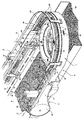
도 1은 본 발명에 따른 이송 장치의 사시도;
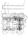
도 2는 도 1의 라인 II-II를 따른 섹션의 확대된 도면;
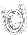
도 3은, 명확성을 위해 제거된 부분을 갖는, 도 1의 이송 장치의 동일 콤퍼넌트의 확대된 사시도이다. Preferred, but non-limiting embodiments of the invention are described by way of example with reference to the accompanying drawings, in which:
1 is a perspective view of a transfer device according to the present invention;
Figure 2 is an enlarged view of a section along line II-II in Figure 1;
3 is an enlarged perspective view of the same component of the transfer device of FIG. 1 with the removed portions for clarity;
도 1 내지 도 3에서 참조번호 1은 포장 머신(도시 생략)을 위한 이송 장치를 전체적으로 가리킨다. 포장 머신은, 저온 살균된 또는 UHT 밀크, 과일 주스, 와인 등과 같은 쏟을 수 있는 식품 생산품의 밀봉된 패키지(2)를 포장 재료(도시 생략)의 공지된 튜브로부터 연속적으로 생산한다. 1 to 3,
튜브는 가열-밀봉 시트 재료의 공지된 웹(도시 생략)을 길이방향으로 접고 밀봉함으로써 공지된 방법으로 형성되는데, 이 웹은 예를 들어, 폴리에틸렌인 가열-밀봉 플라스틱 재료의 층으로 양쪽 측면이 덮인 종이 재료의 층을 포함하여 구성된다. UHT 밀크와 같은 장기 저장 생산품을 위한 무균성 패키지(2)의 경우, 포장 재료는, 예를 들어 알루미늄 호일인 산소-장벽 재료의 층을 포함하여 구성될 수 있으며, 이 층은 식품 생산품과 결국 접촉하는 패키지의 내부 페이스를 형성하는 가열-밀봉 플라스틱 재료의 하나 이상의 층 상에 겹친다. The tube is formed in a known manner by longitudinally folding and sealing a known web (not shown) of a heat-sealing sheet material, which web is, for example, a layer of heat-seal plastic material, And a layer of paper material. In the case of an aseptic package 2 for long-term storage products such as UHT milk, the packaging material may comprise a layer of oxygen-barrier material, for example an aluminum foil, which is in contact with the food product Of the heat-seal plastic material forming the inner face of the package.
그 다음, 포장 재료의 튜브는 포장을 위해 식품 생산품으로 충전되고, 다수의 배게형 팩을 형성하기 위해서 균등하게 이격된 단면을 따라 밀봉 및 절단된 후, 접는 유닛으로 이송하고, 여기서 이들은 각각의 패키지(2)를 형성하기 위해서 기계적으로 접힌다.The tubes of the packaging material are then filled with the food product for packaging, sealed and cut along an evenly spaced cross-section to form a plurality of padded packs, and then transported to a folding unit, (2).
이송 장치(1)는 복수의 접힌 패키지(2)가 접는 유닛에 의해 공급되고, 포장 머신의 단부 스테이션을 규정한다. The
이송 장치(1)는 실질적으로:The transfer device (1) substantially comprises:
- 프레임(3)과;- a frame (3);
- 프레임(3)에 관해서 이동가능하고, 서로 연결된 복수의 링크(4)(몇몇 부분만 도 1 및 2에 나타냄)에 의해 형성되는 루프의 체인 콘베이어(5)와; - a chain conveyor (5) of loops which is movable with respect to the frame (3) and is formed by a plurality of links (4) (some of which are only shown in some of the figures 1 and 2) connected to each other;
- 프레임(3)에 대해서 콘베이어(5)를 지지하기 위한 지지 수단(33)을 포함하여 구성된다.- Support means (33) for supporting the conveyor (5) with respect to the frame (3).
프레임(3)은, 차례로:The
- 축 A의 대향하는 측면 상에서 콘베이어(5)를 둘러싸는 U-형상 바디(6)와; - a U-shaped body (6) surrounding the conveyor (5) on the opposite side of the axis (A);
- 축 A에 관해서 연장하고, 축 A의 측면 상에서 바디(6)에 접속된 환형상 플레이트(7)를 포함하여 구성된다. - an annular plate (7) extending in relation to the axis (A) and connected to the body (6) on the side of the axis (A).
U-형상 바디(6)는, 차례로(도 3):The U-shaped body 6, in turn (Fig. 3)
- 서로 대면하는 한 쌍의 직선형 벽(17)과; - a pair of straight walls (17) facing each other;
- 서로 대면하는 벽(17)에 평행하고, 축 A에 관해서 각각의 벽(17)에 대향하는 한 쌍의 직선형 벽(19)과; - a pair of straight walls (19) parallel to the wall (17) facing each other and opposite each wall (17) with respect to the axis A;
- 축 A에 관해서 반경으로 외부인 벽(17, 19) 사이에 개재된 만곡된 벽(18)을 포함하여 구성된다.- a curved wall (18) interposed between the walls (17, 19) which are radially outward with respect to the axis (A).
반경으로 외부 벽(17, 19) 및 만곡된 벽(18) 모두는 단면이 C-형상이고(도 2):Both the
- 중요 바디(30)와; An
- 바디(30)로부터 축 A를 향해 돌출하는 한 쌍의 상부 및 바닥 윙(31)을 포함하여 구성된다. - a pair of upper and lower wings (31) projecting from the body (30) toward the axis (A).
더욱이, 프레임(3)은:Furthermore, the
- 각각의 벽(18, 19)에 고정되고, 축 A에 대향하는 그들의 측면 상에서 패키지(2)를 포함하도록 적용된 한 쌍의 고정된 가이드(26, 27)와; - a pair of fixed guides (26, 27) fixed to the respective walls (18, 19) and adapted to include the package (2) on their side facing the axis A;
- 벽(19)에 고정되고, 축 A의 측면 상에서 패키지(2)를 포함하도록 적용된 한 쌍의 가이드(28)를 더 포함하여 구성된다. - a pair of guides (28) fixed to the wall (19) and adapted to include the package (2) on the side of the axis (A).
또한, 콘베이어(5)는 작업 브랜치(10)와 복귀 브랜치(11)를 포함하여 구성된다.In addition, the
작업 브랜치(10)는 접는 유닛으로부터 접힌 패키지가 공급되는 수취하는 스테이션과 포장 머신의 단부 스테이션 사이에서 연장하는 경로 P를 따라서 패키지(2)를 반송한다. The working
경로 P는 U-형상이다.The path P is U-shaped.
특히, 작업 브랜치(10)는:In particular, the working
- 접는 유닛으로부터 패키지(2)를 수취하고 이들을 방향 C를 따라 제1센스로 이동시키는 직선형 부분(12)과;- a straight section (12) for receiving the package (2) from the folding unit and moving them along the direction C to the first sense;
- 실질적으로 아크-형상 궤적을 따라서 패키지(2)를 이동시키는 만곡된 부분(13)과; - a curved portion (13) for moving the package (2) along a substantially arc-shaped trajectory;
- 방향 C에 평행하고 이로부터 엇갈리는 방향 D를 따라 그리고 제1센스에 대향하는 제2센스로 패키지(2)를 이동시키는 직선형 부분(14)을 포함하여 구성된다.And a rectilinear section (14) parallel to and oriented in a direction C and moving the package (2) along a staggered direction D and with a second sense opposite to the first sense.
상세하게는, 만곡된 부분(13)은 실질적으로 180°의 원형의 아크 형상이다. In detail, the
부분(14)은 패키지(2)를 포장 머신의 도시 생략된 단부를 향해 이동시킨다.The
매우 동일한 방법으로, 복귀 브랜치(11)는 부분(12, 14) 아래에 배열된 제1및 제2직선형 부분과 제1과 제2직선형 부분 사이에서 부분(13) 아래에 배열된 아크-형상 부분(16)(도 2)을 포함하여 구성된다. In a very similar manner, the
작업 브랜치(10) 및 복귀 브랜치(11)는 서로에 대해서 대향하는 센스로 이동한다. The working
부분(12) 및 복귀 브랜치(11)의 제1부분은 각각의 벽(17)에 의해 그들의 양쪽 측면 상에서 둘러싸이고; 부분(13, 16)은 벽(18)에 의해 축 A에 대향하는 측면 상에서 둘러싸이며; 부분(14) 및 복귀 브랜치(11)의 제2부분은 그들의 측면들 모두에서 각각의 벽(19)에 의해 둘러싸인다.The first portion of the portion 12 and the
가이드(26)는 부분(11, 16)으로 둘러싸이고, 축 A에 관해서 부분(11, 16)의 대향하는 측면 상에 배열된다. The
가이드(27)는 축 A에 관해서 부분(12)의 대향하는 측면 상에 배열된다. The
가이드(28)는 가이드(27)의 전방에서 부분(12)에 대한 축 A의 측면 상에 배열된다. The
상세하게는, 콘베이어(5)는 한 쌍의 풀리(21)에 관해서 루프를 이루는데(도 1에는 하나만 나타냄), 이는 서로 평행한 축에 관해서 회전한다. In detail, the
지지 수단(33)은, 차례로, 프레임(3)에 대한 축 A에 관해서 회전하는 한 쌍의 디스크(8, 9)(도 2 및 3)를 포함하여 구성된다. The supporting means 33 in turn comprises a pair of
도 2에 나타낸 바와 같이, 각각의 링크(4)는 실질적으로:As shown in Figure 2, each link 4 is substantially:
- 디스크(8, 9)로부터 상부로(하부로) 돌출하고, 링크(14)의 상부(바닥) 단부를 규정하는 축 A에 수직인 평면 내에 놓인 플레이트(22)와;A
- 디스크(8, 9) 아래(위)에 배열된 엘리먼트(23)와;- an element (23) arranged below (above) the disc (8, 9);
- 플레이트(22)와 엘리먼트(23) 사이에 축으로 개재된 접속하는 스트레치(24)와; - a connecting stretch (24) interposed axially between the plate (22) and the element (23);
- 스트레치(24)에 대해서 엘리먼트(23)의 대향하는 측면 상에 배열되고, 스트레치(24)보다 낮은 두께를 갖는, 플레이트(22)에 축으로 대향하는 단부(25)를 포함하여 구성된다.Comprises an
상세하게는, 디스크(8, 9)는 콘베이어(5)의 각각의 부분(13, 16)에 의해 지지되고, 도 2에 부분적으로만 나타낸 플레이트(7)에 대해서 축 A에 관해서 회전가능하게 지지된다. In detail, the
바람직하게는, 이송 장치(1)는 경로 P의 하나의 측면 상에 배열되고, 사용 시, 콘베이어(5)의 부분(13)을 따라 추락한 이들 패키지(2)의 배출을 허용하도록 적용된 개구(20)를 포함하여 구성된다. Preferably the conveying
특히, 개구(20)는 튜브 형상이고 축 A에 관해서 연장한다. In particular, the
디스크(8, 9)는 축 A에 관해서 연장하고 축 A에 관해서 개구(20)를 둘러싸는 각각의 관통 보어(39)를 규정한다. The
특히, 축 A에 평행한 디스크(8, 9)의 두께는 축 A에 평행한 개구(20)의 높이 미만이다. In particular, the thickness of the
디스크(8, 9)는 동축이고 대향-회전한다. The
각각의 디스크(8, 9)는:Each
- 서로 축으로 대향하는 한 쌍의 표면(45, 46)과; A pair of surfaces (45, 46) axially opposed to each other;
- 반경으로 내부 단부(47)와;- an inner end (47) at a radius;
- 단부(47)에 대향하고 표면(45, 46) 사이에서 축으로 개재된 반경으로 외부 단부(48)를 포함하여 구성된다.And an
디스크(8, 9)는 서로 대향해서 탑재된다. 특히, 표면(46)은 서로 대면하고, 표면(45) 사이에 축으로 개재된다.The
표면(45, 46)은 디스크(8, 9)의 상부 단부를 규정하는 한편, 표면(46, 45)은 디스크(8, 9)의 바닥 단부를 규정한다. The
디스크(8, 9)의 단부(48)는, 반경 갭과 함께, 대응하는 윙(31)에 관해서, 스트레치(24)의 대향하는 측면 상에 배열된다. The ends 48 of the
디스크(8)는 부분(13)의 동일한 센스로 회전하는 한편, 디스크(9)는 부분(16)의 동일한 센스로 축 A에 관해서 회전한다. The
도 3을 참조로 나타낸 실시형태에 있어서, 디스크(8)는 반시계 방향으로 회전하는 한편, 디스크(9)는 시계 방향으로 회전한다.In the embodiment shown in Fig. 3, the
디스크(8, 9)는 복수의 베어링 엘리먼트(35)를 통해 플레이트(7)에 대한 축 A 관해서 회전가능하게 지지된다.The
플레이트(7)는 축 A에 관해서 환형상이고, 베어링 엘리먼트(35)로 체결된 복수의 반경 돌출부를 포함하여 구성되며, 축 A에 관해서 연장하는 관통 보어(66)를 규정한다. The plate 7 is annular with respect to the axis A and comprises a plurality of radial projections fastened by a bearing
베어링 엘리먼트(35)는 축 A에 평행하고, 이로부터 엇갈리는 관련 축 B에 관해서 연장된다. The bearing
더욱이, 베어링 엘리먼트(35)는 축 A에 관해서 각도로 동일 거리-이격한다.Moreover, the bearing
각각의 베어링 엘리먼트(35)는:Each bearing
- 플레이트(7)에 고정된 중앙 바디(36)와; - a central body (36) fixed to the plate (7);
- 바디(36)에 대해서 관련 축 B에 관해서 회전가능한 한 쌍의 롤러(37, 38)를 포함하여 구성된다. - a pair of rollers (37, 38) rotatable relative to the body (36) relative to the axis (B).
더 상세하게는, 각각의 베어링 엘리먼트(35)의 롤러(37, 38)는 관련 베어링 엘리먼트(35)의 대향하는 축 단부를 규정하고, 바디(36)는 관련 롤러(37, 38) 사이에 축으로 개재된다.More specifically, the
롤러(37, 38)는 상부 및 바닥 베어링(32)의 개재를 통해서 바디(36)에 의해 지지된다(도 2).The
각각의 베어링 엘리먼트(35)의 롤러(37, 38)는 각각의 그루브(40)를 규정한다. The
각각의 디스크(8, 9)의 단부(47)는, 축 A의 측면 상에 배열되고, 관련 롤러(37, 38)의 환형상 그루브(40)와 체결되는 반경 환형상 돌출부를 규정한다.The ends 47 of each of the
각각의 디스크(8, 9)의 단부(48)는 단부(47)에 반경으로 대향하는 반경 환형상 돌출부를 규정하고, 작업 브랜치(10)(복귀 브랜치(11))의 부분(13, 16)을 형성하는 링크(4)에 의해 규정된 환형상 시트(44)에 체결된다. The ends 48 of each of the
특히, 시트(44)는 플레이트(22)와 이들 링크(4)의 엘리먼트(23)에 의해 축으로 경계를 이루는데, 이는 부분(13, 16)을 형성하고, 축 A의 대향하는 측면 상에서, 이들 링크(4)의 스트레치(24)에 의해, 반경으로 경계를 이룬다. In particular the
나타낸 실시형태에 있어서, 단부(47)에 의해 규정된 돌출부는, 단면으로 V-형상이고, 축 A를 향해 수렴하는 한편, 단부(48)에 의해 규정된 돌출부는, 단면으로 L-형상이다. In the embodiment shown, the projections defined by the
바디(36)는 스크루(43)로 서로 접속된 2개의 엘리먼트(68, 69)로 만들어진다. 더욱이, 엘리먼트(68)는 롤러(37)를 지지하고, 엘리먼트(69)는 롤러(38)를 지지한다. The
상부 베어링(32)은 바디(36)의 제1와셔와 엘리먼트(68)로 규정된 제1숄더 사이에 축으로 탑재된다. 제1와셔는 상부 베어링(32)에 대항해서 스크루(41)로 가압된다. The
매우 동일한 방법으로, 바닥 베어링(32)은 제2와셔와 엘리먼트(69)로 규정된 제2숄더 사이에 축으로 탑재된다. 제2와셔는, 스크루(42)에 의해 바닥 베어링(32)에 대항해서 축으로 가압된다. In much the same way, the bottom bearing 32 is axially mounted between a second washer and a second shoulder defined by the
또한, 이송 장치(1)는 축 A에 관해서 디스크(8)와 함께 회전하는 환형상 커버(50)(도 3에서는 도시 생략)를 포함하여 구성된다. The conveying
축 A에 관해서 연장한 커버(50)는 복수의 스크루(51)를 통해서 디스크(8)에 고정되고, 롤러(37)의 상부 단부(49)를 덮는다. The
커버(50)는 실질적으로:The
- 축 A에 수직인 평면 상에 놓이고, 디스크(8)의 표면(45)과 협동하며, 디스크(8)에 스크루 체결된 바닥 표면(52)과;A
- 표면(52)에 대향하는 상부 표면(53)과; An
- 축 A에 관해서 환형상인 측벽(54)과;An
- 표면(52, 53) 사이에서 연장하고, 롤러(37)의 단부(49)에 의해 축으로 이격된 윤곽의 표면(55)을 포함하여 구성된다. And a
또한, 커버(50)는, 축 A에 관해서 연장하고 축 A에 관해서 표면(53)에 대향하는 연속적인 환형상 단차(56)를 포함하여 구성된다. The
단차(56)은 가이드(26)의 대향하는 측면 상에 패키지(2)를 포함한다. The
단차(56)는 콘베이어(5)의 작업 브랜치(10)의 부분(13)을 형성하는 링크(4)의 플레이트(22)의 상부에 배열되고, 이로부터 축 갭에 의해 분리된다. The
표면(53)은 축 A에 관해서 경사를 이루고, 특히 벽(54)으로부터 축 A를 향해 하강해서 진행한다. The
특히, 표면(53)은 선형으로 하강하고, 축 A를 기준으로 해서, 서로 대향하는 반경 외부 단부(57) 및 반경 내부 단부(58)를 포함하여 구성된다. In particular,
또한, 표면(53)의 단부(58)는 개구(20)의 상부 입구 단부를 규정한다. In addition, the
또한, 커버(50) 및 디스크(8)는 축 A의 대향하는 측면 상에서, 부분(13)을 형성하는 링크(4)의 플레이트(22)의 반경으로 내부 단부(29)에 의해 부분적으로 체결된 환형상 숄더(59)를 규정한다. The
숄더(59)는 단차(56)와 디스크(8)의 표면(45) 사이에서 축으로 규정된다. The
특히, 디스크(8)의 표면(45)은 단부(29)에 의해 부분적으로 그리고 표면(52)에 의해 부분적으로 덮인다. In particular, the
디스크(9)의 표면(45)은 복귀 브랜치(11)의 부분(16)을 형성하는 링크(4)의 플레이트(22)의 단부(29)와 축으로 협동한다. The
표면(55)은, 스크루(41)의 헤드로 축 갭과 체결된 환형상 시트(71)를 규정한다. The
더욱이, 이송 장치(1)는 축 A에 관해서 연장하고 개구(20)를 규정하는 바디(60)(도 3에서는 도시 생략)를 포함하여 구성된다. .Furthermore, the conveying
상세하게는, 바디(60)는:Specifically, the
- 반경 갭을 갖는 디스크(8)의 관통 보어(39)를 통과하고, 표면(53)의 단부(58) 아래에 배열된 튜브 형상 엘리먼트(61)와; - a tubular element (61) passing through the through bore (39) of the disk (8) with a radial gap and arranged below the end (58) of the surface (53);
- 축 A의 대향하는 측면 상에서 엘리먼트(61)로부터 돌출하고, 표면(55)과 디스크(8)의 표면(45)의 평면 사이에 축으로 개재된 환형상 플레이트(62)를 포함하여 구성된다. And an annular plate 62 projecting from the
엘리먼트(61)는 개구(20)의 외관을 규정한다. The element (61) defines the appearance of the opening (20).
플레이트(62)는, 축 갭과 함께, 롤러(37)의 단부(49) 위 및 표면(55) 아래에 배열된다. The plate 62 is arranged on the end 49 of the
플레이트(62)는, 이를 통해 스크루(41)의 헤드가 통과하는 복수의 반경 관통 시트(70)를 규정한다. The plate 62 defines a plurality of radially through
또한, 이송 장치(1)는 개구(20) 아래 배열된 부분을 갖는 폐기물 콘베이어(65)를 포함하여 구성된다. 콘베이어(65)는 개구(20)로부터 추락한 패키지(2)를 수취하고, 이들을 포장 머신으로부터 떨어뜨려 이동시키도록 적용된다(도 1).In addition, the conveying
콘베이어(65)는, 나타낸 실시형태에 있어서는 벨트 콘베이어이다.The
실제의 사용에 있어서, 콘베이어(5)의 작업 브랜치(10)는 접는 스테이션으로부터 접힌 패키지(2)를 수취하고, 이들을 경로 P를 따라서 그리고 포장 머신의 단부 스테이션을 향해서 반송한다.In practical use, the working
상세하게는, 접는 유닛은 접힌 패키지(2)를 작업 브랜치(10)의 부분(12)에 공급한다. In particular, the folding unit feeds the folded package 2 to the portion 12 of the working
더욱이, 부분(12)은 패키지(2)를 방향 C에 평행하게 그리고 제1센스로 반송하고, 부분(13)은 아크-형상 부분을 따라서 그리고 축 A에 관해서 반송하며, 부분(14)은 패키지(2)를 방향 D에 평행하게 그리고 제2센스로 반송한다.Furthermore, the portion 12 carries the package 2 in parallel to the direction C and in the first sense, the
콘베이어(5)의 부분(13)은 커버(50)와 함께 축 A에 관해서 회전하는 디스크(8)로 지지된다. 동시에, 복귀 브랜치(11)의 부분(16)은 디스크(8)의 대향하는 센스로 축 A에 관해서 회전하는 디스크(9)에 의해 지지된다. The
콘베이어(5)의 부분(13)을 따라 이동함에 따라서, 패키지(2)는 축 A에 관해서 그들의 반경으로 외부 측면 상에서만 가이드(26)에 의해 포함된다. As the packages 2 travel along the
이들이 콘베이어(5)의 부분(13) 상에 추락한 경우, 패키지(2)는 표면(53) 상으로 미끄러지고; 그 후 추락한 패키지(2)는 단부(58)에 의해 규정된 입구를 통과하고, 개구(20) 내측으로 추락한다. When they fall on the
단차(56)는 그들의 내부 반경 측면 상에, 예를 들어 가이드(26)에 대한 대향하는 측면 상에서, 패키지(2)를 포함시킨다. The
콘베이어(65)는 추락한 패키지(2)를 수취하고, 이들을 포장 머신으로부터 떨어뜨려 반송한다. The
부분(13)을 따라 추락하지 않은 패키지(2)는 작업 브랜치(10)의 부분(14)을 따라 전진하고, 포장 머신의 단부 스테이션에 도달한다. The package 2 that has not fallen along the
복귀 브랜치(11)는 작업 브랜치(10)에 대향해서 이동한다.The
본 발명에 따른 이송 장치(1) 및 방법의 장점은, 상술된 설명으로부터 명확하게 된다. Advantages of the
특히, 이송 장치(1)는 경로 P의 하나의 측면 상에 배열된 개구(20)를 포함하여 구성된다. In particular, the
이 방법으로, 경로 P의 만곡된 부분을 따라 추락한 이들 패키지(2)는 개구(20)를 통과하고, 콘베이어(65)에 도달한다.In this way, these packages 2, which have fallen along the curved portion of the path P, pass through the
따라서, 추락한 이들 패키지(2)는 경로 P의 만곡된 부분을 따라 더 이상 정지하지 않고, 더 이상 이송 장치(1) 및 전체 포장 머신의 중단을 일으키지 않는다.Thus, these fallen packages 2 no longer stop along the curved portion of the path P, and no longer cause interruption of the conveying
개구(20)가 추락한 패키지의 배출을 허용하지 않는다는 사실에 기인해서, 이송 장치(1)는 패키지를 측면에 포함시키기 위해서 내부 반경 가이드의 존재를 더 이상 요구하지 않는다. 따라서, 이송 장치(1)의 설계의 유연성이 개선된다. Due to the fact that the
더욱이, 하강 표면(53)은 개구(20) 내측에서 추락한 패키지(2)의 운동을 용이하게 한다. Furthermore, the falling
최종적으로, 단차(56)는 그들의 반경으로 내부 측면, 예를 들어 가이드(26)의 대향하는 측면 상에서 추락한 패키지(2)를 포함하지 않는다. 이 방법으로, 단차(56)는 패키지(2), 특히 적어도 부분적으로 라운드-형상 단면인 이들이, 그들 자체의 축에 관해서 회전하는 것을 방지한다. Finally, the
그런데, 첨부된 청구항들에서 규정된 보호 범위로부터 벗어남이 없이, 변경이 본 명세서에서 기술되고 도시된 이송 장치(1) 및 방법에 대해서 명확하게 수행될 수 있다.Changes can be made specifically to the
1 - 이송 장치,
2 - 패키지,
5- 콘베이어,
20 - 개구,
56 - 단차,
60 - 바디.1 - transfer device,
2 - Package,
5- Conveyor,
20 - opening,
56 - step,
60 - Body.
Claims (15)
상기 경로(P)의 하나의 측면 상에 배열되고, 사용 시, 상기 경로(P)를 따라 추락한 패키지(2)의 배출을 허용하도록 적용된 관통 개구(20)를 포함하여 구성되는 것을 특징으로 하는 이송 장치.A conveying device (1) for conveying a sealed package (2) of a pourable food product, characterized in that it comprises means (5) for conveying said package (2) along at least partly curved path ≪ / RTI >
And a through opening (20) arranged on one side of the path (P) and adapted to permit, in use, the evacuation of the package (2) that has fallen along the path (P) Conveying device.
상기 개구(20)의 적어도 하나의 부분을 규정하는 정지 중공 제1바디(60)를 포함하여 구성되는 것을 특징으로 하는 이송 장치.The method according to claim 1,
And a stationary hollow first body (60) defining at least one portion of the opening (20).
- 고정된 프레임(3)과;
- 상기 프레임(3)에 관해서 상기 운반하는 수단(5)을 지지하기 위한 지지 수단(33)을 포함하여 구성되고;
상기 지지 수단(33)은, 제1축(A)에 관해서 연장하고 회전할 수 있으며, 상기 경로(P)의 만곡된 부분을 따라 상기 운반하는 수단(5)의 작업 브랜치(10)와 협동하는 적어도 하나의 제1디스크(8)를 포함하여 구성되고, 상기 제1디스크(8)는 상기 개구(20)와 동축이고 이를 둘러싸는 제1관통 보어(39)를 포함하여 구성되는 것을 특징으로 하는 이송 장치.3. The method according to claim 1 or 2,
- a fixed frame (3);
- support means (33) for supporting said conveying means (5) with respect to said frame (3);
Characterized in that the support means (33) extend and rotate with respect to a first axis (A) and cooperate with the working branch (10) of the conveying means (5) along the curved portion of the path Characterized in that it comprises at least one first disc (8), said first disc (8) comprising a first through bore (39) coaxial with and surrounding said opening (20) Conveying device.
상기 지지 수단(33)은, 상기 프레임(3)에 대해서 그리고 상기 제1축(A)에 관해서 상기 적어도 하나의 제1디스크(8)를 회전가능하게 지지하는 베어링 수단(35)을 포함하여 구성되는 것을 특징으로 하는 이송 장치.The method of claim 3,
The support means (33) comprise bearing means (35) for rotatably supporting the at least one first disc (8) with respect to the frame (3) and with respect to the first axis And the conveying device.
상기 베어링 수단(35)은, 상기 축(A)으로부터 반경으로 이격하고 이를 둘러싸는 관련 제2축(B)에 관해서 연장하는 복수의 베어링 엘리먼트(35)를 포함하여 구성되는 것을 특징으로 하는 이송 장치.5. The method of claim 4,
Characterized in that said bearing means (35) comprise a plurality of bearing elements (35) spaced radially from said axis (A) and extending about an associated second axis (B) .
각각의 상기 베어링 엘리먼트(35)는:
- 상기 프레임(3)에 고정된 적어도 하나의 정지 바디(36)와;
- 상기 제2축(B)에 관한 상기 정지 바디(36)에 관해서 회전가능하고, 상기 제1디스크(8)의 제1반경으로 내부 단부(47)에 의해 규정된 제1돌출부와 협동하는 제1그루브(40)를 포함하여 구성되는 제1롤러(37)를, 포함하여 구성되는 것을 특징으로 하는 이송 장치.The method according to claim 4 or 5,
Each said bearing element (35) comprising:
At least one stationary body (36) fixed to said frame (3);
A second disk (8) cooperating with a first projection defined by an inner end (47) with a first radius of said first disk (8), said first disk (8) being rotatable with respect to said stationary body And a first roller (37) including one groove (40).
상기 지지 수단(33)은, 상기 제1디스크(8)에 축으로 대향하고, 상기 제1디스크(8)에 대해서 대향하는 센스로 상기 제1축(A)에 관해서 회전가능한 제2디스크(9)를 포함하여 구성되고;
상기 제2디스크(9)는 상기 경로(P)의 만곡된 부분을 따라 상기 운반하는 수단(5)의 복귀 브랜치(11)와 협동하고; 상기 제2디스크(9)는 상기 개구(20)와 동축이고 이를 둘러싸는 제2관통 보어(39)를 포함하여 구성되는 것을 특징으로 하는 이송 장치.7. The method according to any one of claims 3 to 6,
The support means (33) comprises a second disc (9) which is axially opposed to the first disc (8) and which is rotatable with respect to the first axis (A) with a sense opposite to the first disc ≪ / RTI >
Said second disc (9) cooperating with a return branch (11) of said conveying means (5) along a curved portion of said path (P); Wherein the second disk (9) comprises a second through bore (39) coaxial with and surrounding the opening (20).
제4항 내지 제6항 중 어느 한 항을 인용할 때, 각각의 상기 베어링 엘리먼트(35)는, 상기 제2축(B)에 관한 상기 프레임(3)에 관해서 회전가능하고, 상기 제2디스크(9)의 제2반경으로 내부 단부(47)에 의해 규정된 제2돌출부와 협동하는 제2그루브(40)를 포함하여 구성되는, 제2롤러(38)를 포함하여 구성되는 것을 특징으로 하는 이송 장치.8. The method of claim 7,
A method according to any one of claims 4 to 6, characterized in that each said bearing element (35) is rotatable with respect to said frame (3) with respect to said second axis (B) And a second groove (40) cooperating with a second projection defined by an inner end (47) at a second radius of the first groove (9). Conveying device.
상기 축(A)에 관해서 회전하고, 상기 개구(20)의 입구 단부(58)를 규정할 수 있는 중공 제2바디(50)를 더 포함하여 구성되고; 상기 제2바디(50)는 상기 제1디스크(8)와 접속되는 것을 특징으로 하는 이송 장치.9. The method according to any one of claims 3 to 8,
Further comprising a hollow second body (50) rotatable about said axis (A) and defining an inlet end (58) of said opening (20); And the second body (50) is connected to the first disk (8).
상기 제2바디(50)는, 상기 개구(20)의 대향하는 측면 상에서, 상기 가이드(26)로부터 주어진 반경 거리에 배열된 환형상 단차(56)를 규정하고;
상기 단차(56)는, 사용 시, 상기 경로(P)를 따라 추락하지 않은 상기 패키지(2)를 포함하도록 적용된 것을 특징으로 하는 이송 장치.10. The method of claim 9,
The second body (50) defines, on opposite sides of the opening (20), an annular step (56) arranged at a given radial distance from the guide (26);
Wherein the step (56) is adapted to include the package (2) which, in use, has not fallen along the path (P).
상기 프레임(3)은, 사용 시, 상기 환형상 단차(56)에 대향하는 그 측면 상에서 상기 패키지(2)를 포함하도록 적용된 고정된 가이드(26)를 포함하여 구성되는 것을 특징으로 하는 이송 장치.11. The method of claim 10,
Characterized in that the frame (3) comprises a fixed guide (26) which, in use, is adapted to include the package (2) on its side opposite the annular step (56).
상기 제2바디(50)는, 상기 단차(56)의 대향하는 측면 상에서, 상기 개구(20)를 향해 하강하는, 상기 제1디스크(8)와 함께 회전가능한 표면(53)을 포함하여 구성되고, 상기 개구(20)를 향한 그들의 운동을 용이하게 하기 위해서 상기 추락한 패키지(2)와 미끄럼 가능하게 협동하도록 적용되는 것을 특징으로 하는 이송 장치.12. The method of claim 11,
The second body 50 comprises a surface 53 which is rotatable with the first disc 8 and descends towards the opening 20 on the opposite side of the step 56 Are adapted to slidably cooperate with said fallen package (2) to facilitate their movement towards said opening (20).
상기 개구(20) 아래에 배열되고 상기 운반하는 수단(5)으로부터 상기 배출된 패키지(2)를 떨어뜨려 이동하도록 적용된 폐기물 콘베이어(65)를 포함하여 구성되는 것을 특징으로 하는 이송 장치.The method according to any one of the preceding claims,
And a waste conveyor (65) arranged below said opening (20) and adapted to move away said discharged package (2) from said conveying means (5).
- 상기 밀봉된 패키지(2)를 형성하기 위한 형성 유닛과;
- 상기 항 중 어느 한 항에 따른 이송 장치(1)로서, 상기 형성 유닛으로부터 하류에 배열된 이송 장치를 포함하여 구성되는 것을 특징으로 하는 포장 머신.A packaging machine for producing a sealed package (2) of a pourable food product comprising:
- a forming unit for forming said sealed package (2);
- a conveying device (1) according to any one of the preceding claims, characterized in that it comprises a conveying device arranged downstream from said forming unit.
상기 이송 장치(1)는, 차례로:
- 지지 수단(33)과;
- 상기 지지 수단(33)에 의해 지지되고, 사용 시, 적어도 부분적으로 만곡된 경로(P)를 따라 상기 패키지(2)를 반송하도록 적용된 운반하는 수단(5)을 포함하여 구성되며;
상기 지지 수단(33)에 의해 규정된 개구(20)를 통해 상기 경로(P)를 따라 추락한 이들 상기 패키지(2)를 배출하는 단계를 포함하여 이루어지는 것을 특징으로 하는 제거 방법.CLAIMS 1. A method for removing a fallen encapsulated package (2) of a food product that can be poured from a transfer device (1);
The transfer device 1 comprises, in order:
Support means (33);
- conveying means (5) supported by said support means (33) and adapted for conveying said package (2) along at least partly curved path (P) in use;
And releasing the packages (2) that have fallen along the path (P) through the opening (20) defined by the support means (33).
Applications Claiming Priority (3)
| Application Number | Priority Date | Filing Date | Title |
|---|---|---|---|
| EP11187352.7 | 2011-10-31 | ||
| EP11187352.7A EP2586731B1 (en) | 2011-10-31 | 2011-10-31 | Transfer device for transferring sealed packages of a pourable food product and method of removing fallen sealed packages from the transfer device |
| PCT/EP2012/067246 WO2013064292A1 (en) | 2011-10-31 | 2012-09-05 | Transfer device for transferring sealed packages of a pourable food product and method of removing fallen sealed packages from the transfer device |
Publications (1)
| Publication Number | Publication Date |
|---|---|
| KR20140088084A true KR20140088084A (en) | 2014-07-09 |
Family
ID=46763123
Family Applications (1)
| Application Number | Title | Priority Date | Filing Date |
|---|---|---|---|
| KR1020147008852A KR20140088084A (en) | 2011-10-31 | 2012-09-05 | Transfer device for transferring sealed packages of a pourable food product and method of removing fallen sealed packages from the transfer device |
Country Status (11)
| Country | Link |
|---|---|
| US (1) | US9670009B2 (en) |
| EP (1) | EP2586731B1 (en) |
| JP (1) | JP6062446B2 (en) |
| KR (1) | KR20140088084A (en) |
| CN (1) | CN103635404B (en) |
| BR (1) | BR112014003449A2 (en) |
| ES (1) | ES2480715T3 (en) |
| IN (1) | IN2014CN03036A (en) |
| MX (1) | MX350578B (en) |
| RU (1) | RU2596052C2 (en) |
| WO (1) | WO2013064292A1 (en) |
Families Citing this family (2)
| Publication number | Priority date | Publication date | Assignee | Title |
|---|---|---|---|---|
| EP2586715B1 (en) * | 2011-10-31 | 2014-06-25 | Tetra Laval Holdings & Finance S.A. | Feeding unit for feeding sealed packs of pourable food products and packaging machine comprising such a feeding unit |
| EP2586714B1 (en) | 2011-10-31 | 2014-05-21 | Tetra Laval Holdings & Finance S.A. | Conveyor for an article handling unit, in particular for a folding unit for producing packages of pourable food products |
Family Cites Families (22)
| Publication number | Priority date | Publication date | Assignee | Title |
|---|---|---|---|---|
| US3097732A (en) * | 1961-03-16 | 1963-07-16 | Crompton & Knowles Corp | Apparatus for removing malpositioned articles from a conveyer |
| US3369642A (en) * | 1966-06-17 | 1968-02-20 | Richardson Merrell Inc | Apparatus for removing tipped-over bottles from a conveyor |
| US3610399A (en) * | 1969-09-10 | 1971-10-05 | Ato Inc | Article conveyor having ejecting means for tipped or fallen articles |
| IT1220297B (en) * | 1988-02-25 | 1990-06-15 | Gd Spa | CANDY SELECTOR DEVICE |
| JPH01247317A (en) * | 1988-03-28 | 1989-10-03 | Masao Matsumoto | Material arranging device |
| US5009550A (en) * | 1989-08-30 | 1991-04-23 | Simplimatic Engineering Company | Article handling device with low profile side guides |
| US5299675A (en) * | 1990-11-09 | 1994-04-05 | T L Feeding Systems, Inc. | Pouch feeder method and device with angled rim |
| US5564551A (en) * | 1994-12-23 | 1996-10-15 | Hoppmann Corporation | Puck conveying mechanism and method |
| DE19653090C1 (en) * | 1996-12-20 | 1998-06-25 | Hugo Schindel | Device for separating and transporting bottles and molded parts |
| DK0887268T3 (en) * | 1997-06-27 | 2004-03-08 | Tetra Laval Holdings & Finance | Unit for transferring and tipping sealed packages containing pourable food |
| JP2968238B2 (en) * | 1997-09-19 | 1999-10-25 | 日本イーライリリー株式会社 | Falling bottle removing apparatus and its operation method |
| JP2001019144A (en) | 1999-07-13 | 2001-01-23 | Hitachi Zosen Corp | Container conveying device for washing machine |
| JP2001106332A (en) * | 1999-10-11 | 2001-04-17 | Yoshitaka Aoyama | Ejection device for abnormal projection nut |
| ES2228286B1 (en) | 2004-10-25 | 2006-02-16 | Jaime Marti Sala | ITEM POSITIONER. |
| JP5186399B2 (en) | 2009-01-22 | 2013-04-17 | 四国化工機株式会社 | Container molding equipment |
| JP5537277B2 (en) | 2009-12-13 | 2014-07-02 | 日本テトラパック株式会社 | Liquid filling device |
| JP2011126700A (en) | 2009-12-21 | 2011-06-30 | Kirin Techno-System Co Ltd | Fallen container removing guide for conveyor |
| EP2586715B1 (en) | 2011-10-31 | 2014-06-25 | Tetra Laval Holdings & Finance S.A. | Feeding unit for feeding sealed packs of pourable food products and packaging machine comprising such a feeding unit |
| ES2535810T3 (en) | 2011-10-31 | 2015-05-18 | Tetra Laval Holdings & Finance S.A. | Folding unit and method to produce containers of food products that can be poured |
| ES2508141T3 (en) | 2011-10-31 | 2014-10-16 | Tetra Laval Holdings & Finance S.A. | Folding unit for packaging machines for food products that can be poured |
| ES2484698T3 (en) | 2011-10-31 | 2014-08-12 | Tetra Laval Holdings & Finance S.A. | Folding unit to produce folded containers of pourable food products from corresponding sealed containers |
| EP2586714B1 (en) | 2011-10-31 | 2014-05-21 | Tetra Laval Holdings & Finance S.A. | Conveyor for an article handling unit, in particular for a folding unit for producing packages of pourable food products |
-
2011
- 2011-10-31 EP EP11187352.7A patent/EP2586731B1/en active Active
- 2011-10-31 ES ES11187352.7T patent/ES2480715T3/en active Active
-
2012
- 2012-09-05 KR KR1020147008852A patent/KR20140088084A/en not_active Application Discontinuation
- 2012-09-05 IN IN3036CHN2014 patent/IN2014CN03036A/en unknown
- 2012-09-05 WO PCT/EP2012/067246 patent/WO2013064292A1/en active Application Filing
- 2012-09-05 US US14/127,520 patent/US9670009B2/en active Active
- 2012-09-05 MX MX2014004790A patent/MX350578B/en active IP Right Grant
- 2012-09-05 CN CN201280032832.0A patent/CN103635404B/en active Active
- 2012-09-05 BR BR112014003449A patent/BR112014003449A2/en not_active Application Discontinuation
- 2012-09-05 RU RU2014121887/11A patent/RU2596052C2/en not_active IP Right Cessation
- 2012-09-05 JP JP2014537534A patent/JP6062446B2/en active Active
Also Published As
| Publication number | Publication date |
|---|---|
| WO2013064292A1 (en) | 2013-05-10 |
| EP2586731B1 (en) | 2014-05-21 |
| US20140123595A1 (en) | 2014-05-08 |
| MX350578B (en) | 2017-09-11 |
| RU2596052C2 (en) | 2016-08-27 |
| ES2480715T3 (en) | 2014-07-28 |
| US9670009B2 (en) | 2017-06-06 |
| RU2014121887A (en) | 2015-12-10 |
| CN103635404A (en) | 2014-03-12 |
| JP2014534936A (en) | 2014-12-25 |
| IN2014CN03036A (en) | 2015-07-03 |
| EP2586731A1 (en) | 2013-05-01 |
| BR112014003449A2 (en) | 2017-03-14 |
| CN103635404B (en) | 2016-06-15 |
| MX2014004790A (en) | 2014-05-30 |
| JP6062446B2 (en) | 2017-01-18 |
Similar Documents
| Publication | Publication Date | Title |
|---|---|---|
| US9120584B2 (en) | Folding unit for pourable food product packaging machines | |
| KR20140086965A (en) | Feeding unit and method for feeding sealed packs of pourable food products | |
| US10086966B2 (en) | Folding unit for pourable food product packaging machines | |
| US9027732B2 (en) | Unit for transferring and up-ending sealed packages of pourable food products | |
| JP6356811B2 (en) | Transport unit for transporting sealed packs of injectable food | |
| WO2022157080A1 (en) | Infeed conveyor for a folding apparatus, folding apparatus having an infeed conveyor and packaging machine having a folding apparatus | |
| MX2011002967A (en) | Gluing unit for applying adhesive to a succession of opening devices for gluing to sealed packages of food products pourable into a tube of packaging material. | |
| JP6685931B2 (en) | Supply unit for supplying sealed packs of liquid food | |
| US10093484B2 (en) | Feeding unit for feeding sealed packs of pourable food products | |
| KR20140088084A (en) | Transfer device for transferring sealed packages of a pourable food product and method of removing fallen sealed packages from the transfer device | |
| US9527678B2 (en) | Unit for transferring and up-ending sealed packages containing a pourable food product | |
| JP7115980B2 (en) | Jam detection device, method for detecting defective packages in filling machine, folding unit for producing packages of liquid food in filling machine, and filling machine | |
| WO2023198615A1 (en) | Infeed conveyor for a folding apparatus, folding apparatus having an infeed conveyor and packaging machine having a folding apparatus | |
| WO2024083645A1 (en) | Infeed conveyor for a folding apparatus, folding apparatus having an infeed conveyor and packaging machine having a folding apparatus |
Legal Events
| Date | Code | Title | Description |
|---|---|---|---|
| A201 | Request for examination | ||
| E902 | Notification of reason for refusal | ||
| E601 | Decision to refuse application |