KR20140068678A - Power transmission system of hybrid electric vehicle - Google Patents
Power transmission system of hybrid electric vehicle Download PDFInfo
- Publication number
- KR20140068678A KR20140068678A KR1020120136468A KR20120136468A KR20140068678A KR 20140068678 A KR20140068678 A KR 20140068678A KR 1020120136468 A KR1020120136468 A KR 1020120136468A KR 20120136468 A KR20120136468 A KR 20120136468A KR 20140068678 A KR20140068678 A KR 20140068678A
- Authority
- KR
- South Korea
- Prior art keywords
- rotary element
- clutch
- gear set
- planetary gear
- element comprises
- Prior art date
Links
Images


Classifications
-
- B—PERFORMING OPERATIONS; TRANSPORTING
- B60—VEHICLES IN GENERAL
- B60K—ARRANGEMENT OR MOUNTING OF PROPULSION UNITS OR OF TRANSMISSIONS IN VEHICLES; ARRANGEMENT OR MOUNTING OF PLURAL DIVERSE PRIME-MOVERS IN VEHICLES; AUXILIARY DRIVES FOR VEHICLES; INSTRUMENTATION OR DASHBOARDS FOR VEHICLES; ARRANGEMENTS IN CONNECTION WITH COOLING, AIR INTAKE, GAS EXHAUST OR FUEL SUPPLY OF PROPULSION UNITS IN VEHICLES
- B60K6/00—Arrangement or mounting of plural diverse prime-movers for mutual or common propulsion, e.g. hybrid propulsion systems comprising electric motors and internal combustion engines ; Control systems therefor, i.e. systems controlling two or more prime movers, or controlling one of these prime movers and any of the transmission, drive or drive units Informative references: mechanical gearings with secondary electric drive F16H3/72; arrangements for handling mechanical energy structurally associated with the dynamo-electric machine H02K7/00; machines comprising structurally interrelated motor and generator parts H02K51/00; dynamo-electric machines not otherwise provided for in H02K see H02K99/00
- B60K6/20—Arrangement or mounting of plural diverse prime-movers for mutual or common propulsion, e.g. hybrid propulsion systems comprising electric motors and internal combustion engines ; Control systems therefor, i.e. systems controlling two or more prime movers, or controlling one of these prime movers and any of the transmission, drive or drive units Informative references: mechanical gearings with secondary electric drive F16H3/72; arrangements for handling mechanical energy structurally associated with the dynamo-electric machine H02K7/00; machines comprising structurally interrelated motor and generator parts H02K51/00; dynamo-electric machines not otherwise provided for in H02K see H02K99/00 the prime-movers consisting of electric motors and internal combustion engines, e.g. HEVs
- B60K6/22—Arrangement or mounting of plural diverse prime-movers for mutual or common propulsion, e.g. hybrid propulsion systems comprising electric motors and internal combustion engines ; Control systems therefor, i.e. systems controlling two or more prime movers, or controlling one of these prime movers and any of the transmission, drive or drive units Informative references: mechanical gearings with secondary electric drive F16H3/72; arrangements for handling mechanical energy structurally associated with the dynamo-electric machine H02K7/00; machines comprising structurally interrelated motor and generator parts H02K51/00; dynamo-electric machines not otherwise provided for in H02K see H02K99/00 the prime-movers consisting of electric motors and internal combustion engines, e.g. HEVs characterised by apparatus, components or means specially adapted for HEVs
- B60K6/36—Arrangement or mounting of plural diverse prime-movers for mutual or common propulsion, e.g. hybrid propulsion systems comprising electric motors and internal combustion engines ; Control systems therefor, i.e. systems controlling two or more prime movers, or controlling one of these prime movers and any of the transmission, drive or drive units Informative references: mechanical gearings with secondary electric drive F16H3/72; arrangements for handling mechanical energy structurally associated with the dynamo-electric machine H02K7/00; machines comprising structurally interrelated motor and generator parts H02K51/00; dynamo-electric machines not otherwise provided for in H02K see H02K99/00 the prime-movers consisting of electric motors and internal combustion engines, e.g. HEVs characterised by apparatus, components or means specially adapted for HEVs characterised by the transmission gearings
- B60K6/365—Arrangement or mounting of plural diverse prime-movers for mutual or common propulsion, e.g. hybrid propulsion systems comprising electric motors and internal combustion engines ; Control systems therefor, i.e. systems controlling two or more prime movers, or controlling one of these prime movers and any of the transmission, drive or drive units Informative references: mechanical gearings with secondary electric drive F16H3/72; arrangements for handling mechanical energy structurally associated with the dynamo-electric machine H02K7/00; machines comprising structurally interrelated motor and generator parts H02K51/00; dynamo-electric machines not otherwise provided for in H02K see H02K99/00 the prime-movers consisting of electric motors and internal combustion engines, e.g. HEVs characterised by apparatus, components or means specially adapted for HEVs characterised by the transmission gearings with the gears having orbital motion
-
- B—PERFORMING OPERATIONS; TRANSPORTING
- B60—VEHICLES IN GENERAL
- B60K—ARRANGEMENT OR MOUNTING OF PROPULSION UNITS OR OF TRANSMISSIONS IN VEHICLES; ARRANGEMENT OR MOUNTING OF PLURAL DIVERSE PRIME-MOVERS IN VEHICLES; AUXILIARY DRIVES FOR VEHICLES; INSTRUMENTATION OR DASHBOARDS FOR VEHICLES; ARRANGEMENTS IN CONNECTION WITH COOLING, AIR INTAKE, GAS EXHAUST OR FUEL SUPPLY OF PROPULSION UNITS IN VEHICLES
- B60K6/00—Arrangement or mounting of plural diverse prime-movers for mutual or common propulsion, e.g. hybrid propulsion systems comprising electric motors and internal combustion engines ; Control systems therefor, i.e. systems controlling two or more prime movers, or controlling one of these prime movers and any of the transmission, drive or drive units Informative references: mechanical gearings with secondary electric drive F16H3/72; arrangements for handling mechanical energy structurally associated with the dynamo-electric machine H02K7/00; machines comprising structurally interrelated motor and generator parts H02K51/00; dynamo-electric machines not otherwise provided for in H02K see H02K99/00
- B60K6/20—Arrangement or mounting of plural diverse prime-movers for mutual or common propulsion, e.g. hybrid propulsion systems comprising electric motors and internal combustion engines ; Control systems therefor, i.e. systems controlling two or more prime movers, or controlling one of these prime movers and any of the transmission, drive or drive units Informative references: mechanical gearings with secondary electric drive F16H3/72; arrangements for handling mechanical energy structurally associated with the dynamo-electric machine H02K7/00; machines comprising structurally interrelated motor and generator parts H02K51/00; dynamo-electric machines not otherwise provided for in H02K see H02K99/00 the prime-movers consisting of electric motors and internal combustion engines, e.g. HEVs
- B60K6/42—Arrangement or mounting of plural diverse prime-movers for mutual or common propulsion, e.g. hybrid propulsion systems comprising electric motors and internal combustion engines ; Control systems therefor, i.e. systems controlling two or more prime movers, or controlling one of these prime movers and any of the transmission, drive or drive units Informative references: mechanical gearings with secondary electric drive F16H3/72; arrangements for handling mechanical energy structurally associated with the dynamo-electric machine H02K7/00; machines comprising structurally interrelated motor and generator parts H02K51/00; dynamo-electric machines not otherwise provided for in H02K see H02K99/00 the prime-movers consisting of electric motors and internal combustion engines, e.g. HEVs characterised by the architecture of the hybrid electric vehicle
-
- B—PERFORMING OPERATIONS; TRANSPORTING
- B60—VEHICLES IN GENERAL
- B60K—ARRANGEMENT OR MOUNTING OF PROPULSION UNITS OR OF TRANSMISSIONS IN VEHICLES; ARRANGEMENT OR MOUNTING OF PLURAL DIVERSE PRIME-MOVERS IN VEHICLES; AUXILIARY DRIVES FOR VEHICLES; INSTRUMENTATION OR DASHBOARDS FOR VEHICLES; ARRANGEMENTS IN CONNECTION WITH COOLING, AIR INTAKE, GAS EXHAUST OR FUEL SUPPLY OF PROPULSION UNITS IN VEHICLES
- B60K6/00—Arrangement or mounting of plural diverse prime-movers for mutual or common propulsion, e.g. hybrid propulsion systems comprising electric motors and internal combustion engines ; Control systems therefor, i.e. systems controlling two or more prime movers, or controlling one of these prime movers and any of the transmission, drive or drive units Informative references: mechanical gearings with secondary electric drive F16H3/72; arrangements for handling mechanical energy structurally associated with the dynamo-electric machine H02K7/00; machines comprising structurally interrelated motor and generator parts H02K51/00; dynamo-electric machines not otherwise provided for in H02K see H02K99/00
- B60K6/20—Arrangement or mounting of plural diverse prime-movers for mutual or common propulsion, e.g. hybrid propulsion systems comprising electric motors and internal combustion engines ; Control systems therefor, i.e. systems controlling two or more prime movers, or controlling one of these prime movers and any of the transmission, drive or drive units Informative references: mechanical gearings with secondary electric drive F16H3/72; arrangements for handling mechanical energy structurally associated with the dynamo-electric machine H02K7/00; machines comprising structurally interrelated motor and generator parts H02K51/00; dynamo-electric machines not otherwise provided for in H02K see H02K99/00 the prime-movers consisting of electric motors and internal combustion engines, e.g. HEVs
- B60K6/22—Arrangement or mounting of plural diverse prime-movers for mutual or common propulsion, e.g. hybrid propulsion systems comprising electric motors and internal combustion engines ; Control systems therefor, i.e. systems controlling two or more prime movers, or controlling one of these prime movers and any of the transmission, drive or drive units Informative references: mechanical gearings with secondary electric drive F16H3/72; arrangements for handling mechanical energy structurally associated with the dynamo-electric machine H02K7/00; machines comprising structurally interrelated motor and generator parts H02K51/00; dynamo-electric machines not otherwise provided for in H02K see H02K99/00 the prime-movers consisting of electric motors and internal combustion engines, e.g. HEVs characterised by apparatus, components or means specially adapted for HEVs
- B60K6/38—Arrangement or mounting of plural diverse prime-movers for mutual or common propulsion, e.g. hybrid propulsion systems comprising electric motors and internal combustion engines ; Control systems therefor, i.e. systems controlling two or more prime movers, or controlling one of these prime movers and any of the transmission, drive or drive units Informative references: mechanical gearings with secondary electric drive F16H3/72; arrangements for handling mechanical energy structurally associated with the dynamo-electric machine H02K7/00; machines comprising structurally interrelated motor and generator parts H02K51/00; dynamo-electric machines not otherwise provided for in H02K see H02K99/00 the prime-movers consisting of electric motors and internal combustion engines, e.g. HEVs characterised by apparatus, components or means specially adapted for HEVs characterised by the driveline clutches
- B60K6/387—Actuated clutches, i.e. clutches engaged or disengaged by electric, hydraulic or mechanical actuating means
-
- B—PERFORMING OPERATIONS; TRANSPORTING
- B60—VEHICLES IN GENERAL
- B60K—ARRANGEMENT OR MOUNTING OF PROPULSION UNITS OR OF TRANSMISSIONS IN VEHICLES; ARRANGEMENT OR MOUNTING OF PLURAL DIVERSE PRIME-MOVERS IN VEHICLES; AUXILIARY DRIVES FOR VEHICLES; INSTRUMENTATION OR DASHBOARDS FOR VEHICLES; ARRANGEMENTS IN CONNECTION WITH COOLING, AIR INTAKE, GAS EXHAUST OR FUEL SUPPLY OF PROPULSION UNITS IN VEHICLES
- B60K6/00—Arrangement or mounting of plural diverse prime-movers for mutual or common propulsion, e.g. hybrid propulsion systems comprising electric motors and internal combustion engines ; Control systems therefor, i.e. systems controlling two or more prime movers, or controlling one of these prime movers and any of the transmission, drive or drive units Informative references: mechanical gearings with secondary electric drive F16H3/72; arrangements for handling mechanical energy structurally associated with the dynamo-electric machine H02K7/00; machines comprising structurally interrelated motor and generator parts H02K51/00; dynamo-electric machines not otherwise provided for in H02K see H02K99/00
- B60K6/20—Arrangement or mounting of plural diverse prime-movers for mutual or common propulsion, e.g. hybrid propulsion systems comprising electric motors and internal combustion engines ; Control systems therefor, i.e. systems controlling two or more prime movers, or controlling one of these prime movers and any of the transmission, drive or drive units Informative references: mechanical gearings with secondary electric drive F16H3/72; arrangements for handling mechanical energy structurally associated with the dynamo-electric machine H02K7/00; machines comprising structurally interrelated motor and generator parts H02K51/00; dynamo-electric machines not otherwise provided for in H02K see H02K99/00 the prime-movers consisting of electric motors and internal combustion engines, e.g. HEVs
- B60K6/42—Arrangement or mounting of plural diverse prime-movers for mutual or common propulsion, e.g. hybrid propulsion systems comprising electric motors and internal combustion engines ; Control systems therefor, i.e. systems controlling two or more prime movers, or controlling one of these prime movers and any of the transmission, drive or drive units Informative references: mechanical gearings with secondary electric drive F16H3/72; arrangements for handling mechanical energy structurally associated with the dynamo-electric machine H02K7/00; machines comprising structurally interrelated motor and generator parts H02K51/00; dynamo-electric machines not otherwise provided for in H02K see H02K99/00 the prime-movers consisting of electric motors and internal combustion engines, e.g. HEVs characterised by the architecture of the hybrid electric vehicle
- B60K6/44—Series-parallel type
- B60K6/445—Differential gearing distribution type
-
- F—MECHANICAL ENGINEERING; LIGHTING; HEATING; WEAPONS; BLASTING
- F16—ENGINEERING ELEMENTS AND UNITS; GENERAL MEASURES FOR PRODUCING AND MAINTAINING EFFECTIVE FUNCTIONING OF MACHINES OR INSTALLATIONS; THERMAL INSULATION IN GENERAL
- F16H—GEARING
- F16H3/00—Toothed gearings for conveying rotary motion with variable gear ratio or for reversing rotary motion
- F16H3/02—Toothed gearings for conveying rotary motion with variable gear ratio or for reversing rotary motion without gears having orbital motion
-
- B—PERFORMING OPERATIONS; TRANSPORTING
- B60—VEHICLES IN GENERAL
- B60K—ARRANGEMENT OR MOUNTING OF PROPULSION UNITS OR OF TRANSMISSIONS IN VEHICLES; ARRANGEMENT OR MOUNTING OF PLURAL DIVERSE PRIME-MOVERS IN VEHICLES; AUXILIARY DRIVES FOR VEHICLES; INSTRUMENTATION OR DASHBOARDS FOR VEHICLES; ARRANGEMENTS IN CONNECTION WITH COOLING, AIR INTAKE, GAS EXHAUST OR FUEL SUPPLY OF PROPULSION UNITS IN VEHICLES
- B60K6/00—Arrangement or mounting of plural diverse prime-movers for mutual or common propulsion, e.g. hybrid propulsion systems comprising electric motors and internal combustion engines ; Control systems therefor, i.e. systems controlling two or more prime movers, or controlling one of these prime movers and any of the transmission, drive or drive units Informative references: mechanical gearings with secondary electric drive F16H3/72; arrangements for handling mechanical energy structurally associated with the dynamo-electric machine H02K7/00; machines comprising structurally interrelated motor and generator parts H02K51/00; dynamo-electric machines not otherwise provided for in H02K see H02K99/00
- B60K6/20—Arrangement or mounting of plural diverse prime-movers for mutual or common propulsion, e.g. hybrid propulsion systems comprising electric motors and internal combustion engines ; Control systems therefor, i.e. systems controlling two or more prime movers, or controlling one of these prime movers and any of the transmission, drive or drive units Informative references: mechanical gearings with secondary electric drive F16H3/72; arrangements for handling mechanical energy structurally associated with the dynamo-electric machine H02K7/00; machines comprising structurally interrelated motor and generator parts H02K51/00; dynamo-electric machines not otherwise provided for in H02K see H02K99/00 the prime-movers consisting of electric motors and internal combustion engines, e.g. HEVs
- B60K6/22—Arrangement or mounting of plural diverse prime-movers for mutual or common propulsion, e.g. hybrid propulsion systems comprising electric motors and internal combustion engines ; Control systems therefor, i.e. systems controlling two or more prime movers, or controlling one of these prime movers and any of the transmission, drive or drive units Informative references: mechanical gearings with secondary electric drive F16H3/72; arrangements for handling mechanical energy structurally associated with the dynamo-electric machine H02K7/00; machines comprising structurally interrelated motor and generator parts H02K51/00; dynamo-electric machines not otherwise provided for in H02K see H02K99/00 the prime-movers consisting of electric motors and internal combustion engines, e.g. HEVs characterised by apparatus, components or means specially adapted for HEVs
- B60K6/38—Arrangement or mounting of plural diverse prime-movers for mutual or common propulsion, e.g. hybrid propulsion systems comprising electric motors and internal combustion engines ; Control systems therefor, i.e. systems controlling two or more prime movers, or controlling one of these prime movers and any of the transmission, drive or drive units Informative references: mechanical gearings with secondary electric drive F16H3/72; arrangements for handling mechanical energy structurally associated with the dynamo-electric machine H02K7/00; machines comprising structurally interrelated motor and generator parts H02K51/00; dynamo-electric machines not otherwise provided for in H02K see H02K99/00 the prime-movers consisting of electric motors and internal combustion engines, e.g. HEVs characterised by apparatus, components or means specially adapted for HEVs characterised by the driveline clutches
- B60K2006/381—Arrangement or mounting of plural diverse prime-movers for mutual or common propulsion, e.g. hybrid propulsion systems comprising electric motors and internal combustion engines ; Control systems therefor, i.e. systems controlling two or more prime movers, or controlling one of these prime movers and any of the transmission, drive or drive units Informative references: mechanical gearings with secondary electric drive F16H3/72; arrangements for handling mechanical energy structurally associated with the dynamo-electric machine H02K7/00; machines comprising structurally interrelated motor and generator parts H02K51/00; dynamo-electric machines not otherwise provided for in H02K see H02K99/00 the prime-movers consisting of electric motors and internal combustion engines, e.g. HEVs characterised by apparatus, components or means specially adapted for HEVs characterised by the driveline clutches characterized by driveline brakes
-
- B—PERFORMING OPERATIONS; TRANSPORTING
- B60—VEHICLES IN GENERAL
- B60K—ARRANGEMENT OR MOUNTING OF PROPULSION UNITS OR OF TRANSMISSIONS IN VEHICLES; ARRANGEMENT OR MOUNTING OF PLURAL DIVERSE PRIME-MOVERS IN VEHICLES; AUXILIARY DRIVES FOR VEHICLES; INSTRUMENTATION OR DASHBOARDS FOR VEHICLES; ARRANGEMENTS IN CONNECTION WITH COOLING, AIR INTAKE, GAS EXHAUST OR FUEL SUPPLY OF PROPULSION UNITS IN VEHICLES
- B60K6/00—Arrangement or mounting of plural diverse prime-movers for mutual or common propulsion, e.g. hybrid propulsion systems comprising electric motors and internal combustion engines ; Control systems therefor, i.e. systems controlling two or more prime movers, or controlling one of these prime movers and any of the transmission, drive or drive units Informative references: mechanical gearings with secondary electric drive F16H3/72; arrangements for handling mechanical energy structurally associated with the dynamo-electric machine H02K7/00; machines comprising structurally interrelated motor and generator parts H02K51/00; dynamo-electric machines not otherwise provided for in H02K see H02K99/00
- B60K6/20—Arrangement or mounting of plural diverse prime-movers for mutual or common propulsion, e.g. hybrid propulsion systems comprising electric motors and internal combustion engines ; Control systems therefor, i.e. systems controlling two or more prime movers, or controlling one of these prime movers and any of the transmission, drive or drive units Informative references: mechanical gearings with secondary electric drive F16H3/72; arrangements for handling mechanical energy structurally associated with the dynamo-electric machine H02K7/00; machines comprising structurally interrelated motor and generator parts H02K51/00; dynamo-electric machines not otherwise provided for in H02K see H02K99/00 the prime-movers consisting of electric motors and internal combustion engines, e.g. HEVs
- B60K6/42—Arrangement or mounting of plural diverse prime-movers for mutual or common propulsion, e.g. hybrid propulsion systems comprising electric motors and internal combustion engines ; Control systems therefor, i.e. systems controlling two or more prime movers, or controlling one of these prime movers and any of the transmission, drive or drive units Informative references: mechanical gearings with secondary electric drive F16H3/72; arrangements for handling mechanical energy structurally associated with the dynamo-electric machine H02K7/00; machines comprising structurally interrelated motor and generator parts H02K51/00; dynamo-electric machines not otherwise provided for in H02K see H02K99/00 the prime-movers consisting of electric motors and internal combustion engines, e.g. HEVs characterised by the architecture of the hybrid electric vehicle
- B60K6/48—Parallel type
- B60K2006/4833—Step up or reduction gearing driving generator, e.g. to operate generator in most efficient speed range
- B60K2006/4841—Step up or reduction gearing driving generator, e.g. to operate generator in most efficient speed range the gear provides shifting between multiple ratios
-
- F—MECHANICAL ENGINEERING; LIGHTING; HEATING; WEAPONS; BLASTING
- F16—ENGINEERING ELEMENTS AND UNITS; GENERAL MEASURES FOR PRODUCING AND MAINTAINING EFFECTIVE FUNCTIONING OF MACHINES OR INSTALLATIONS; THERMAL INSULATION IN GENERAL
- F16H—GEARING
- F16H37/00—Combinations of mechanical gearings, not provided for in groups F16H1/00 - F16H35/00
- F16H37/02—Combinations of mechanical gearings, not provided for in groups F16H1/00 - F16H35/00 comprising essentially only toothed or friction gearings
- F16H37/06—Combinations of mechanical gearings, not provided for in groups F16H1/00 - F16H35/00 comprising essentially only toothed or friction gearings with a plurality of driving or driven shafts; with arrangements for dividing torque between two or more intermediate shafts
- F16H37/08—Combinations of mechanical gearings, not provided for in groups F16H1/00 - F16H35/00 comprising essentially only toothed or friction gearings with a plurality of driving or driven shafts; with arrangements for dividing torque between two or more intermediate shafts with differential gearing
- F16H37/0833—Combinations of mechanical gearings, not provided for in groups F16H1/00 - F16H35/00 comprising essentially only toothed or friction gearings with a plurality of driving or driven shafts; with arrangements for dividing torque between two or more intermediate shafts with differential gearing with arrangements for dividing torque between two or more intermediate shafts, i.e. with two or more internal power paths
- F16H37/084—Combinations of mechanical gearings, not provided for in groups F16H1/00 - F16H35/00 comprising essentially only toothed or friction gearings with a plurality of driving or driven shafts; with arrangements for dividing torque between two or more intermediate shafts with differential gearing with arrangements for dividing torque between two or more intermediate shafts, i.e. with two or more internal power paths at least one power path being a continuously variable transmission, i.e. CVT
- F16H2037/0866—Power split variators with distributing differentials, with the output of the CVT connected or connectable to the output shaft
- F16H2037/0873—Power split variators with distributing differentials, with the output of the CVT connected or connectable to the output shaft with switching, e.g. to change ranges
-
- F—MECHANICAL ENGINEERING; LIGHTING; HEATING; WEAPONS; BLASTING
- F16—ENGINEERING ELEMENTS AND UNITS; GENERAL MEASURES FOR PRODUCING AND MAINTAINING EFFECTIVE FUNCTIONING OF MACHINES OR INSTALLATIONS; THERMAL INSULATION IN GENERAL
- F16H—GEARING
- F16H37/00—Combinations of mechanical gearings, not provided for in groups F16H1/00 - F16H35/00
- F16H37/02—Combinations of mechanical gearings, not provided for in groups F16H1/00 - F16H35/00 comprising essentially only toothed or friction gearings
- F16H37/06—Combinations of mechanical gearings, not provided for in groups F16H1/00 - F16H35/00 comprising essentially only toothed or friction gearings with a plurality of driving or driven shafts; with arrangements for dividing torque between two or more intermediate shafts
- F16H37/08—Combinations of mechanical gearings, not provided for in groups F16H1/00 - F16H35/00 comprising essentially only toothed or friction gearings with a plurality of driving or driven shafts; with arrangements for dividing torque between two or more intermediate shafts with differential gearing
- F16H37/0833—Combinations of mechanical gearings, not provided for in groups F16H1/00 - F16H35/00 comprising essentially only toothed or friction gearings with a plurality of driving or driven shafts; with arrangements for dividing torque between two or more intermediate shafts with differential gearing with arrangements for dividing torque between two or more intermediate shafts, i.e. with two or more internal power paths
- F16H37/084—Combinations of mechanical gearings, not provided for in groups F16H1/00 - F16H35/00 comprising essentially only toothed or friction gearings with a plurality of driving or driven shafts; with arrangements for dividing torque between two or more intermediate shafts with differential gearing with arrangements for dividing torque between two or more intermediate shafts, i.e. with two or more internal power paths at least one power path being a continuously variable transmission, i.e. CVT
- F16H2037/088—Power split variators with summing differentials, with the input of the CVT connected or connectable to the input shaft
-
- F—MECHANICAL ENGINEERING; LIGHTING; HEATING; WEAPONS; BLASTING
- F16—ENGINEERING ELEMENTS AND UNITS; GENERAL MEASURES FOR PRODUCING AND MAINTAINING EFFECTIVE FUNCTIONING OF MACHINES OR INSTALLATIONS; THERMAL INSULATION IN GENERAL
- F16H—GEARING
- F16H2200/00—Transmissions for multiple ratios
- F16H2200/003—Transmissions for multiple ratios characterised by the number of forward speeds
- F16H2200/0034—Transmissions for multiple ratios characterised by the number of forward speeds the gear ratios comprising two forward speeds
-
- F—MECHANICAL ENGINEERING; LIGHTING; HEATING; WEAPONS; BLASTING
- F16—ENGINEERING ELEMENTS AND UNITS; GENERAL MEASURES FOR PRODUCING AND MAINTAINING EFFECTIVE FUNCTIONING OF MACHINES OR INSTALLATIONS; THERMAL INSULATION IN GENERAL
- F16H—GEARING
- F16H2200/00—Transmissions for multiple ratios
- F16H2200/20—Transmissions using gears with orbital motion
- F16H2200/2002—Transmissions using gears with orbital motion characterised by the number of sets of orbital gears
- F16H2200/2007—Transmissions using gears with orbital motion characterised by the number of sets of orbital gears with two sets of orbital gears
-
- F—MECHANICAL ENGINEERING; LIGHTING; HEATING; WEAPONS; BLASTING
- F16—ENGINEERING ELEMENTS AND UNITS; GENERAL MEASURES FOR PRODUCING AND MAINTAINING EFFECTIVE FUNCTIONING OF MACHINES OR INSTALLATIONS; THERMAL INSULATION IN GENERAL
- F16H—GEARING
- F16H2200/00—Transmissions for multiple ratios
- F16H2200/20—Transmissions using gears with orbital motion
- F16H2200/203—Transmissions using gears with orbital motion characterised by the engaging friction means not of the freewheel type, e.g. friction clutches or brakes
- F16H2200/2038—Transmissions using gears with orbital motion characterised by the engaging friction means not of the freewheel type, e.g. friction clutches or brakes with three engaging means
-
- Y—GENERAL TAGGING OF NEW TECHNOLOGICAL DEVELOPMENTS; GENERAL TAGGING OF CROSS-SECTIONAL TECHNOLOGIES SPANNING OVER SEVERAL SECTIONS OF THE IPC; TECHNICAL SUBJECTS COVERED BY FORMER USPC CROSS-REFERENCE ART COLLECTIONS [XRACs] AND DIGESTS
- Y02—TECHNOLOGIES OR APPLICATIONS FOR MITIGATION OR ADAPTATION AGAINST CLIMATE CHANGE
- Y02T—CLIMATE CHANGE MITIGATION TECHNOLOGIES RELATED TO TRANSPORTATION
- Y02T10/00—Road transport of goods or passengers
- Y02T10/60—Other road transportation technologies with climate change mitigation effect
- Y02T10/62—Hybrid vehicles
-
- Y—GENERAL TAGGING OF NEW TECHNOLOGICAL DEVELOPMENTS; GENERAL TAGGING OF CROSS-SECTIONAL TECHNOLOGIES SPANNING OVER SEVERAL SECTIONS OF THE IPC; TECHNICAL SUBJECTS COVERED BY FORMER USPC CROSS-REFERENCE ART COLLECTIONS [XRACs] AND DIGESTS
- Y10—TECHNICAL SUBJECTS COVERED BY FORMER USPC
- Y10S—TECHNICAL SUBJECTS COVERED BY FORMER USPC CROSS-REFERENCE ART COLLECTIONS [XRACs] AND DIGESTS
- Y10S903/00—Hybrid electric vehicles, HEVS
- Y10S903/902—Prime movers comprising electrical and internal combustion motors
Abstract
Description
본 발명은 하이브리드 자동차의 동력전달장치에 관한 것으로서, 보다 상세하게는 엔진 동력의 분기 시 기계적 동력전달경로의 비중을 높여 전기 부하를 줄이고 엔진의 최대 동력을 사용할 수 있도록 함으로써, 발진 시 엔진 모드를 대체하여 모드 변환 횟수를 줄이고, 모드 변환 시 모든 회전요소의 회전수 변화를 최소화할 수 있도록 하는 하이브리드 자동차의 동력전달장치에 관한 것이다.[0001] The present invention relates to a power transmission apparatus for a hybrid vehicle, and more particularly, to a power transmission apparatus for a hybrid vehicle, which increases the weight of a mechanical power transmission path when an engine power is branched, Thereby reducing the number of times of mode conversion and minimizing the change in the number of revolutions of all the rotating elements at the time of mode conversion.
자동차의 친환경 기술은 미래 자동차 산업의 생존이 달린 핵심기술로서, 선진 자동차 메이커들은 환경 및 연비 규제를 달성하기 위한 친환경 자동차 개발에 총력을 기울이고 있다.The environmentally friendly technology of automobiles is a core technology with survival of the future automobile industry, and advanced automobile manufacturers are concentrating on development of environmentally friendly vehicles to achieve environmental and fuel efficiency regulations.
이에 따라 각 자동차 메이커들은 전기 자동차(EV : Electric Vehicle), 하이브리드 전기 자동차(HEV : Hybrid Electric Vehicle), 연료전지 자동차(FCEV : Fuel Cell Electric Vehicle)등을 미래형 자동차 기술로서 개발하고 있다.Accordingly, automobile manufacturers are developing electric vehicles (EVs), hybrid electric vehicles (HEVs), and fuel cell electric vehicles (FCEVs) as futuristic automobile technologies.
상기와 같은 미래형 자동차는 중량 및 원가 등 여러 가지 기술적인 제약이 있기 때문에 자동차 메이커에서는 배기가스 규제를 만족시키고, 연비 성능의 향상을 위한 현실적인 문제의 대안으로서 하이브리드 자동차에 주목하고 있으며, 이를 실용화하기 위해 치열한 경쟁을 벌이고 있다. Because the above-mentioned future type of automobile has various technical limitations such as weight and cost, automakers pay attention to the hybrid vehicle as an alternative to realistic problems for satisfying exhaust gas regulations and improving fuel efficiency, and in order to put them into practical use There is intense competition.
하이브리드 자동차는 2개 이상의 에너지원(Power Source)을 사용하는 자동차로서, 여러 가지 방식으로 조합될 수 있으며, 에너지원으로는 기존의 화석 연료를 사용하는 가솔린 엔진 또는 디젤 엔진과 전기 에너지에 의하여 구동되는 모터/제너레이터가 혼합되어 사용된다.A hybrid vehicle is a vehicle using two or more power sources and can be combined in various ways. The energy source is a gasoline engine or a diesel engine using conventional fossil fuel, The motor / generator is mixed and used.
이러한 하이브리드 자동차는 저속에서 상대적으로 저속토크 특성이 좋은 모터/제너레이터를 주동력원으로 사용하고, 고속에서는 상대적으로 고속토크 특성이 좋은 엔진을 주동력원으로 사용한다.Such a hybrid vehicle uses a motor / generator having a relatively low torque characteristic at a low speed as a main power source and an engine having a relatively high torque characteristic at a high speed as a main power source.
이에 따라 하이브리드 자동차는 저속구간에서 화석 연료를 사용하는 엔진의 작동이 정지되고 모터/제너레이터를 사용하기 때문에 연비 개선과 배기가스의 저감에 우수한 효과가 있다.Accordingly, the hybrid vehicle has an excellent effect in improving fuel economy and reducing exhaust gas because the engine using the fossil fuel is stopped in the low speed section and the motor / generator is used.
그리고 상기와 같은 하이브리드 자동차의 동력전달장치는 단일모드 방식과 다중모드 방식으로 분류된다.The power transmission devices of the hybrid vehicle are classified into a single mode mode and a multimode mode.
상기 단일모드 방식은 변속제어를 위한 클러치 및 브레이크와 같은 토크전달기구가 필요하지 않다는 장점은 있으나, 고속 주행 시 효율이 저하되어 연비가 낮고 대형 자동차에 적용하기 위해서는 부가적인 토크 증배 장치가 필요하다는 단점이 있다.The single-mode system has an advantage in that a torque transmission mechanism such as a clutch and a brake for the shift control is not required. However, the efficiency is lowered at high speed driving and the fuel mileage is low and an additional torque multiplication device is required for application to a large- .
상기 다중모드 방식은 고속 주행 시 효율이 높고, 자체적으로 토크 증배가 가능하도록 설계할 수 있어 중대형 자동차에 적용이 가능하다는 장점이 있다.The multi-mode system can be designed to have high efficiency during high-speed traveling and to be capable of torque multiplication by itself, which is advantageous in that it can be applied to a middle- or large-sized vehicle.
이에 따라 최근에는 단일모드 방식보다는 다중모드 방식을 주로 채택하고 있으며, 그에 따른 연구가 활발하게 진행되고 있다.Accordingly, a multimode method is mainly used rather than a single mode method, and studies are actively pursued.
상기 다중모드 방식의 동력전달장치는 복수의 유성기어세트와, 모터 및 발전기로 사용되는 복수의 모터/제너레이터와, 상기 유성기어세트의 회전요소를 제어할 수 있는 복수의 토크전달기구(마찰요소)와, 상기 모터/제너레이터의 동력원으로 사용되는 배터리 등을 포함하여 이루어진다.The multimode type power transmission apparatus includes a plurality of planetary gear sets, a plurality of motor / generators used as motors and generators, a plurality of torque transmission mechanisms (friction elements) capable of controlling the rotation elements of the planetary gear set, And a battery used as a power source of the motor / generator.
이러한 다중모드 방식의 동력전달장치는 상기의 유성기어세트, 모터/제너레이터, 토크전달기구의 연결 구성에 따라 상이한 작동 메카니즘을 갖는다. Such a multimode type power transmission apparatus has a different operating mechanism depending on the connection configuration of the above-mentioned planetary gear set, the motor / generator, and the torque transmission mechanism.
또한, 상기 다중모드 방식의 동력전달장치는 그 연결 구성에 따라 내구성, 동력전달효율, 크기 등이 달라지는 특성이 있기 때문에 하이브리드 자동차의 동력전달장치 분야에서는 보다 견고하고, 동력손실이 없으며, 콤팩트한 동력전달장치를 구현하기 위한 연구 개발이 지속되고 있다.In addition, since the multimode type power transmission device has characteristics such as durability, power transmission efficiency, size and the like depending on its connection configuration, it is more robust in the power transmission device field of a hybrid vehicle, Research and development for implementing a transmission device is continuing.
본 발명의 실시 예는 엔진 동력의 분기 시 기계적 동력전달경로의 비중을 높여 전기 부하를 줄이고 엔진의 최대 동력을 사용할 수 있도록 함으로써, 발진 시 엔진 모드를 대체하여 모드 변환 횟수를 줄이고, 모드 변환 시 모든 회전요소의 회전수 변화를 최소화할 수 있도록 하는 하이브리드 자동차의 동력전달장치를 제공하고자 한다.The embodiment of the present invention reduces the number of mode conversions by replacing the engine mode at the time of oscillation by reducing the electrical load and using the maximum power of the engine by increasing the proportion of the mechanical power transmission path at the time of branching the engine power, So that the change in the number of revolutions of the rotating element can be minimized.
본 발명의 하나 또는 다수의 실시 예에서는 엔진의 동력이 입력되는 입력축; 상기 입력축과 소정의 간격을 두고 평행하게 배치되는 출력축; 상기 입력축상에 배치되어 제1 회전요소가 제1 모터/제너레이터와 연결되고, 제2 회전요소가 출력요소로 작동하며, 제3 회전요소가 상기 입력축과 직접 연결됨과 동시에 제2 모터/제네레이터와 연결되는 제1 유성기어세트; 상기 출력축상에 배치되어 상기 제4 회전요소가 선택적으로 상기 제3 회전요소와 외접 기어 연결되고, 제5 회전요소가 상기 제2 회전요소와 외접 기어 연결됨과 동시에 출력축과 연결되며, 제6 회전요소가 변속기 하우징과 선택적으로 연결되는 제2 유성기어세트; 상기 제2 유성기어세트의 3개의 회전요소 중, 2개의 회전요소를 선택적으로 연결하는 직결수단; 상기 외접 기어 연결부에 배치되는 트랜스퍼 기어; 상기 선택적 연결부에 배치되는 마찰요소를 포함하여 이루어지는 하이브리드 자동차의 동력전달장치을 제공할 수 있다. In one or more embodiments of the present invention, an input shaft to which engine power is input; An output shaft disposed parallel to the input shaft at a predetermined interval; A first rotary element is connected to the first motor / generator, a second rotary element is operated as an output element, a third rotary element is directly connected to the input shaft, and the second rotary element is connected to the second motor / A first planetary gear set; The fourth rotary element is selectively connected to the third rotary element and the external gear is connected to the output shaft, the fifth rotary element is connected to the external gear and is connected to the output shaft, A second planetary gear set selectively connected to the transmission housing; A direct connection means for selectively connecting two rotary elements among the three rotary elements of the second planetary gear set; A transfer gear disposed at the external gear connecting portion; And a friction element disposed in the optional connection portion.
또한, 상기 제1 유성기어세트는 싱글 피니언 유성기어세트로서, 제1 회전요소는 제1 선기어, 제2 회전요소는 제1 유성캐리어, 제3 회전요소는 제1 링기어로 이루어지며, 상기 제2 유성기어세트는 싱글 피니언 유성기어세트로서, 제4 회전요소는 제2 선기어, 제5 회전요소는 제2 유성캐리어, 제6 회전요소는 제2 링기어로 이루어질 수 있다. The first planetary gear set is a single pinion planetary gear set, wherein the first rotating element is composed of a first sun gear, the second rotating element is composed of a first planet carrier, and the third rotating element is composed of a first ring gear, 2 planetary gear set may be a single pinion planetary gear set, the fourth rotating element may comprise a second sun gear, the fifth rotating element may comprise a second planet carrier, and the sixth rotating element may comprise a second ring gear.
또한, 상기 제1 유성기어세트는 더블 피니언 유성기어세트로서, 제1 회전요소는 제1 선기어, 제2 회전요소는 제1 링기어, 제3 회전요소는 제1 유성캐리어로 이루어지며, 상기 제2 유성기어세트는 싱글 피니언 유성기어세트로서, 제4 회전요소는 제2 선기어, 제5 회전요소는 제2 유성캐리어, 제6 회전요소는 제2 링기어로 이루어질 수 있다. The first planetary gear set is a double pinion planetary gear set. The first planetary gear set includes a first sun gear, a second sun gear, a first ring gear, and a third sun gear. The first planetary gear set includes a first sun gear, 2 planetary gear set may be a single pinion planetary gear set, the fourth rotating element may comprise a second sun gear, the fifth rotating element may comprise a second planet carrier, and the sixth rotating element may comprise a second ring gear.
또한, 상기 제1 유성기어세트는 싱글 피니언 유성기어세트로서, 제1 회전요소는 제1 선기어, 제2 회전요소는 제1 유성캐리어, 제3 회전요소는 제1 링기어로 이루어지며, 상기 제2 유성기어세트는 더블 피니언 유성기어세트로서, 제4 회전요소는 제2 선기어, 제5 회전요소는 제2 링기어, 제6 회전요소는 제2 유성캐리어로 이루어질 수 있다. The first planetary gear set is a single pinion planetary gear set, wherein the first rotating element is composed of a first sun gear, the second rotating element is composed of a first planet carrier, and the third rotating element is composed of a first ring gear, 2 planetary gear set may be a double pinion planetary gear set, the fourth rotating element may be a second sun gear, the fifth rotating element may be a second ring gear, and the sixth rotating element may be a second planetary carrier.
또한, 상기 직결수단은 제4 회전요소와 제5 회전요소 사이에 배치되는 제1 클러치(CL1)로 이루어질 수 있다. The direct coupling means may comprise a first clutch CL1 disposed between the fourth rotary element and the fifth rotary element.
또한, 상기 직결수단은 제4 회전요소와 제6 회전요소 사이에 배치되는 제1 클러치(CL1)로 이루어질 수 있다. The direct coupling means may comprise a first clutch CL1 disposed between the fourth rotary element and the sixth rotary element.
또한, 상기 직결수단은 제5 회전요소와 제6 회전요소 사이에 배치되는 제1 클러치(CL1)로 이루어질 수 있다. Further, the direct coupling means may comprise a first clutch CL1 disposed between the fifth rotating element and the sixth rotating element.
또한, 상기 트랜스퍼 기어는 제2 회전요소와 제5 회전요소 사이에 배치되는 제1 트랜스퍼 기어; 제3 회전요소와 제4 회전요소 사이에 배치되는 제2 트랜스퍼 기어를 포함할 수 있다. The transfer gear may include a first transfer gear disposed between the second rotary element and the fifth rotary element; And a second transfer gear disposed between the third rotating element and the fourth rotating element.
또한, 상기 마찰요소는 제6 회전요소와 변속기 하우징 사이에 배치되는 브레이크; 제3 회전요소와 제2 트랜스퍼 기어 사이에 배치되는 제2 클러치를 포함할 수 있다. The friction element also includes a brake disposed between the sixth rotating element and the transmission housing; And a second clutch disposed between the third rotating element and the second transfer gear.
또한, 상기 마찰요소는 상기 제6 회전요소와 변속기 하우징 사이에 배치되는 브레이크; 상기 제4 회전요소와 제2 트랜스퍼 기어 사이에 배치되는 제2 클러치를 포함할 수 있다. Further, the friction element may include a brake disposed between the sixth rotating element and the transmission housing; And a second clutch disposed between the fourth rotary element and the second transfer gear.
또한, 상기 직결수단을 형성하는 제1 클러치와, 상기 마찰요소를 형성하는 브레이크 및 제2 클러치는 EV 모드 1에서 브레이크가 작동되고, EV 모드 2에서 제1 클러치가 작동되며, 하이브리드 입력분기 모드 1에서 브레이크가 작동되고, 하이브리드 입력분기 모드 2에서 제1 클러치가 작동되며, 하이브리드 복합분기 모드에서 제2 클러치가 작동되고, 엔진 모드 1에서 제2 클러치와 브레이크가 동시에 작동되며, 엔진 모드 2에서 제1 클러치와 제2 클러치가 동시에 작동될 수 있다. Further, the first clutch that forms the direct coupling means, the brake and the second clutch that form the friction element are operated in the brake mode in the
본 발명의 실시 예는 전체적인 구성에 있어서, 2개의 유성기어세트와 외접기어인 2개의 트랜스퍼 기어, 그리고 3개의 마찰요소와 2개의 모터/제너레이터의 조합으로 2개의 EV 모드와, 2개의 하이브리드 입력분기 모드와, 1개의 하이브리드 복합분기 모드, 2개의 엔진 모드를 구현할 수 있다.The embodiment of the present invention is characterized in that, in the overall configuration, two EV modes are provided by a combination of two planetary gear sets and two transfer gears, which are external gears, and a combination of three friction elements and two motor / Mode, one hybrid hybrid branching mode, and two engine modes.
또한, 유성기어세트 외에 외접 기어인 2개의 트랜스퍼 기어를 적용함으로써, 자유로운 기어 잇수 변경으로 차량별 최적의 기어비를 설정할 수 있으며, 요구 성능 조건에 맞도록 기어 변경이 가능하여 발진 성능을 향상시킬 수 있다.Furthermore, by applying two transfer gears, which are external gears, in addition to the planetary gear set, it is possible to set the optimum gear ratio for each vehicle by changing the number of gear teeth freely and it is possible to change gears to meet required performance conditions, .
그리고 작용 효과면에 있어서, WOT(Wide Open Throttle)발진시 충분한 동력 성능을 제공하여 엔진 모드로의 변환을 억제하고, 하이브리드 입력분기 모드와 복합분기 모드의 변환 시, 엔진의 최대 동력을 사용할 수 있다.In terms of the operation effect, it provides sufficient power performance in WOT (Wide Open Throttle) oscillation to suppress the conversion to the engine mode, and to use the maximum power of the engine when converting the hybrid input branch mode and the hybrid branch mode .
또한, 엔진 동력을 분기함에 있어서, 기계적 동력전달경로의 비중을 높여 전기 부하를 줄이고 엔진의 최대 동력을 사용할 수 있도록 함으로써, 발진 시, 엔진 모드를 대체하여 모드 변환 횟수를 줄이고, 모드 변환시 모든 회전요소의 회전수 변화를 최소화할 수 있다.In addition, when the engine power is branched, the weight of the mechanical power transmission path is increased to reduce the electric load and the maximum power of the engine can be used, thereby reducing the number of mode conversions by replacing the engine mode at the time of oscillation, The change in the number of revolutions of the motor can be minimized.
그리고 엔진 모드를 제공하여 고속 주행 시, 모터/제너레이터의 전기 부하 없이 주행이 가능하도록 하여 연비를 향상시킬 수 있다.The engine mode is provided so that the vehicle can be driven without an electric load of the motor / generator during high speed traveling, thereby improving fuel efficiency.
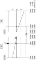
도 1은 본 발명의 제1 실시 예에 따른 동력전달장치의 구성도이다.
도 2는 본 발명의 제1 실시 예에 따른 동력전달장치에 적용되는 마찰요소의 각 작동모드별 작동표이다.
도 3a는 본 발명의 제1 실시 예에 따른 동력전달장치의 EV 모드 1에서의 레버 해석도이다.
도 3b는 본 발명의 제1 실시 예에 따른 동력전달장치의 EV 모드 2에서의 레버 해석도이다.
도 4a는 본 발명의 제1 실시 예에 따른 동력전달장치의 하이브리드 입력 분기 모드 1에서의 레버 해석도이다.
도 4b는 본 발명의 제1 실시 예에 따른 동력전달장치의 하이브리드 입력 분기 모드 2에서의 레버 해석도이다.
도 5는 본 발명의 제1 실시 예에 따른 동력전달장치의 하이브리드 복합 분기 모드에서의 레버 해석도이다.
도 6a는 본 발명의 제1 실시 예에 따른 동력전달장치의 엔진 모드 1에서의 레버 해석도이다.
도 6b는 본 발명의 제1 실시 예에 따른 동력전달장치의 엔진 모드 2에서의 레버 해석도이다.
도 7은 본 발명의 제2 실시 예에 따른 동력전달장치의 구성도이다.
도 8은 본 발명의 제3 실시 예에 따른 동력전달장치의 구성도이다.
도 9는 본 발명의 제4 실시 예에 따른 동력전달장치의 구성도이다.
도 10은 본 발명의 제5 실시 예에 따른 동력전달장치의 구성도이다.
도 11은 본 발명의 제6 실시 예에 따른 동력전달장치의 구성도이다.1 is a configuration diagram of a power transmitting apparatus according to a first embodiment of the present invention.
2 is an operation table for each operation mode of a friction element applied to the power transmitting apparatus according to the first embodiment of the present invention.
3A is a lever analysis diagram in
FIG. 3B is a lever analysis diagram in EV mode 2 of the power transmitting apparatus according to the first embodiment of the present invention. FIG.
4A is a lever analysis diagram in a hybrid
4B is a lever analysis diagram in the hybrid input branch mode 2 of the power transmission apparatus according to the first embodiment of the present invention.
5 is a lever analysis diagram in hybrid hybrid branching mode of the power transmitting apparatus according to the first embodiment of the present invention.
6A is a lever analysis diagram in
6B is a lever analysis diagram in engine mode 2 of the power transmitting apparatus according to the first embodiment of the present invention.
7 is a configuration diagram of a power transmitting apparatus according to a second embodiment of the present invention.
8 is a configuration diagram of a power transmitting apparatus according to a third embodiment of the present invention.
9 is a configuration diagram of a power transmitting apparatus according to a fourth embodiment of the present invention.
10 is a configuration diagram of a power transmitting apparatus according to a fifth embodiment of the present invention.
11 is a configuration diagram of a power transmitting apparatus according to a sixth embodiment of the present invention.
이하, 본 발명의 실시 예들을 첨부한 도면을 통하여 상세하게 설명한다. Hereinafter, embodiments of the present invention will be described in detail with reference to the accompanying drawings.
단, 본 발명의 실시 예를 명확하게 설명하기 위하여 설명과 관계없는 부분은 생략하였으며, 명세서 전체를 통하여 동일 또는 유사한 구성요소에 대해서는 동일한 도면부호를 적용하여 설명한다.In order to clearly illustrate the embodiments of the present invention, parts that are not related to the description are omitted, and the same or similar components are denoted by the same reference numerals throughout the entire specification.
하기의 설명에서 구성의 명칭을 제1, 제2 등으로 구분한 것은 그 구성의 명칭이 동일하여 이를 구분하기 위한 것으로, 반드시 그 순서에 한정되는 것은 아니다.In the following description, the names of the components are denoted by the first, second, etc. in order to distinguish them from each other because the names of the components are the same and are not necessarily limited to the order.
도 1은 본 발명의 제1 실시 예에 따른 하이브리드 자동차의 동력전달장치에 대한 구성도이다.FIG. 1 is a configuration diagram of a power transmission apparatus for a hybrid vehicle according to a first embodiment of the present invention.
도 1을 참조하면, 본 발명의 제1 실시 예에 따른 하이브리드 자동차의 동력전달장치는 입력축(IS)상에 배치되는 제1 유성기어세트(PG1)와, 상기 입력축(IS)과 평행하게 배치되는 출력축(OS)상에 배치되는 제2 유성기어세트(PG2)와, 2개의 트랜스퍼 기어(TF1)(TF2)와, 2개의 클러치(CL1)(CL2)와 1개 브레이크(BK)로 이루어지는 마찰요소와, 2개의 모터/제너레이터(MG1)(MG2)를 포함하여 이루어진다.1, a power transmission apparatus for a hybrid vehicle according to a first embodiment of the present invention includes a first planetary gear set PG1 disposed on an input shaft IS, A second planetary gear set PG2 disposed on the output shaft OS, two transfer gears TF1 and TF2, a friction element composed of two clutches CL1 and CL2 and one brake BK, And two motor / generators MG1 and MG2.
이에 따라 상기 제1, 제2 유성기어세트(PG1)(PG2)는 입력축(IS)으로부터 입력되는 엔진(ENG)의 회전동력과, 제1, 제2 모터/제너레이터(MG1)(MG2)의 회전동력을 상호 보완작동으로 변속하여 상기 출력축(OS)을 통해 출력한다.Accordingly, the first and second planetary gear sets PG1 and PG2 are rotated by the rotation power of the engine ENG input from the input shaft IS and the rotation of the first and second motor / generators MG1 and MG2 The power is shifted to the complementary operation and output through the output shaft OS.
상기 입력축(IS)은 입력부재로서 엔진(ENG)의 회전동력을 전달받으며, 상기 출력축(OS)은 출력부재로서 미도시한 차동장치를 통해 구동륜을 구동시키도록 구동력을 전달한다.The input shaft IS receives the rotational power of the engine ENG as an input member and the output shaft OS transmits a driving force to drive the drive wheel through an unillustrated differential device as an output member.
상기 제1 유성기어세트(PG1)는 싱글 피니언 유성기어세트로서, 제1 선기어(S1)로 이루어지는 제1 회전요소(N1)와, 상기 제1 선기어(S1)와 외접으로 맞물리는 제1 피니언(P1)을 지지하는 제1 유성 캐리어(PC1)로 이루어지는 제2 회전요소(N2)와, 상기 제1 피니언(P1)과 내접으로 맞물리는 제1 링기어(R1)로 이루어지는 제3 회전요소(N3)를 포함하여 이루어진다.The first planetary gear set PG1 is a single pinion planetary gear set and includes a first rotary element N1 composed of a first sun gear S1 and a first sun gear S1 having a first pinion A third rotary element N3 composed of a first ring gear R1 meshing with the first pinion P1 in an insulated manner and a second rotary element N2 composed of a first planetary carrier PC1 supporting the first pinion P1, ).
상기 제2 유성기어세트(PG2)는 싱글 피니언 유성기어세트로서, 제2 선기어(S2)로 이루어지는 제4 회전요소(N4)와, 상기 제2 선기어(S2)와 외접으로 맞물리는 제2 피니언(P2)을 지지하는 제2 유성 캐리어(PC2)로 이루어지는 제5 회전요소(N5)와, 상기 제2 피니언(P2)과 내접으로 맞물리는 제2 링기어(R2)로 이루어지는 제6 회전요소(N6)를 포함하여 이루어진다.The second planetary gear set PG2 is a single pinion planetary gear set and includes a fourth rotary element N4 composed of a second sun gear S2 and a second pinion gear N2 that externally engages with the second sun gear S2 A fifth rotary element N5 composed of a second planetary carrier PC2 supporting the second pinion P2 and a sixth rotary element N6 composed of a second ring gear R2 meshing with the second pinion P2 in an inscribed- ).
상기 제1 유성기어세트(PG1)는 제3 회전요소(N3)가 입력축(IS)과 직접 연결되며, 상기 제2 유성기어세트(PG2)는 제5 회전요소(N5)가 출력축(OS)과 직접 연결된다. The first planetary gear set PG1 is configured such that the third rotating element N3 is directly connected to the input shaft IS and the second planetary gearset PG2 is connected to the output shaft OS, Directly connected.
상기 제1, 제2 유성기어세트(PG1)(PG2)는 제1, 제2 트랜스퍼 기어(TF1)(TF2)와 제1, 제2 클러치(CL1)(CL2), 그리고 브레이크(BK)에 의하여 조합된다.The first and second planetary gear sets PG1 and PG2 are driven by the first and second transfer gears TF1 and TF2 and the first and second clutches CL1 and CL2 and the brake BK .
상기 제1, 제2 트랜스퍼 기어(TF1)(TF2)는 각각 서로 외접하는 제1, 제2 트랜스퍼 드라이브 기어(TF1a)(TF2a)와, 제1, 제2 트랜스퍼 드리븐 기어(TF1b)(TF2b)를 포함하여 이루어진다.The first and second transfer gears TF1 and TF2 include first and second transfer drive gears TF1a and TF2a that are in contact with each other and first and second transfer driven gears TF1b and TF2b, .
상기 제1 트랜스퍼 기어(TF1)는 제2 회전요소(N2)와 제5 회전요소(N5)를 외접 기어 연결할 수 있도록 배치된다.The first transfer gear TF1 is arranged to connect the second rotary element N2 and the fifth rotary element N5 to the external gears.
상기 제2 트랜스퍼 기어(TF2)는 입력축(IS)을 포함하는 제3 회전요소(N3)와 제4 회전요소(N4)를 외접 기어 연결할 수 있도록 배치된다.The second transfer gear TF2 is disposed so as to connect the third rotary element N3 including the input shaft IS and the fourth rotary element N4 to the external gears.
이에 따라 상기 제1, 제2 트랜스퍼 기어(TF1)(TF2)에 의하여 연결되는 각각의 회전요소는 그 기어비에 따라 상호 반대방향으로 회전하게 되며, 상기 제1 트랜스퍼 기어(TF1)는 동속 전달이 이루어지고, 제2 트랜스퍼 기어(TF1)는 증속 전달이 이루어질 수 있도록 기어비가 설정된다.Accordingly, each of the rotary elements connected by the first and second transfer gears TF1 and TF2 rotates in opposite directions according to the gear ratio, and the first transfer gear TF1 is transmitted at the same speed And the gear ratio is set so that the second transfer gear TF1 can perform the increased speed transmission.
그리고 마찰요소인 제1, 2 클러치(CL1)(CL2)와 브레이크(BK)는 다음과 같이 배치된다.The first and second clutches CL1, CL2 and the brake BK, which are friction elements, are arranged as follows.
상기 제1 클러치(CL1)는 제4 회전요소(N4)와 제5 회전요소(N5)를 선택적으로 연결할 수 있도록 배치되어 직결수단을 작용한다. The first clutch CL1 is disposed so as to selectively connect the fourth rotary element N4 and the fifth rotary element N5 to act as direct coupling means.
상기 제2 클러치(CL2)는 입력축(IS)을 포함하는 제3 회전요소(N3)와 제2 트랜스퍼 기어(TF2)를 선택적으로 연결할 수 있도록 배치된다.The second clutch CL2 is disposed to selectively connect the third rotary element N3 including the input shaft IS and the second transfer gear TF2.
이에 따라 상기 제1 클러치(CL1)는 제2 유성기어세트(PG2)의 2개의 회전요소를 선택적으로 연결하여 제2 유성기어세트(PG2)가 선택적으로 직결의 상태가 되도록 하는 직결수단이며, 제2 클러치(CL2)는 입력축(IS)의 회전동력이 선택적으로 제4 회전요소(N4)로 전달될 수 있도록 한다.Accordingly, the first clutch CL1 is a direct coupling means for selectively coupling the two rotary elements of the second planetary gear set PG2 to selectively bring the second planetary gear set PG2 into a direct coupling state, The second clutch CL2 allows the rotational power of the input shaft IS to be selectively transmitted to the fourth rotary element N4.
또한, 상기 브레이크(BK) 제6 회전요소(N6)와 변속기 하우징(H)을 선택적으로 연결할 수 있도록 배치된다.And is arranged to selectively connect the sixth rotary element N6 of the brake BK and the transmission housing H. [
상기에서 제1, 제2 클러치(CL1)(CL2)와 브레이크(BK)로 이루어지는 각 마찰요소는 유압에 의하여 마찰 결합되는 다판식 유압마찰결합유닛으로 이루어질 수 있다. In this case, each of the friction elements constituted by the first and second clutches CL1, CL2 and the brake BK may be a multi-plate hydraulic frictional coupling unit frictionally coupled by hydraulic pressure.
상기 제1 모터/제너레이터(MG1)와 제2 모터/제너레이터(MG2)는 각각 독립적인 동력원으로서, 모터와 제너레이터 기능을 갖는다.The first motor / generator MG1 and the second motor / generator MG2 are independent power sources, and have a motor and a generator function.
상기 제1 모터/제너레이터(MG1)는 상기 제1 유성기어세트(PG1)의 제1 회전요소(N1)와 연결되어 회전동력을 공급하는 모터로 작동하거나, 상기 제1 회전요소(N1)의 회전력에 의하여 회전하면서 전기를 생성하는 발전기 역할을 수행하게 된다.The first motor / generator MG1 is connected to the first rotary element N1 of the first planetary gear set PG1 to operate as a motor for supplying rotational power, or the rotational force of the first rotary element N1 So as to generate electricity.
상기 제2 모터/제너레이터(MG2)는 상기 제2 트랜스퍼 드라이브 기어(TF2a)와 연결되어 회전동력을 공급하는 모터로 작동하거나, 상기 제2 트랜스퍼 기어(TF2a)의 회전력에 의하여 회전하면서 전기를 생성하는 발전기 역할을 수행하게 된다. The second motor / generator MG2 is connected to the second transfer drive gear TF2a to operate as a motor that supplies rotational power, or generates electricity by rotating by the rotational force of the second transfer gear TF2a It will act as a generator.
이를 위하여 상기 제1 모터/제너레이터(MG1)와 제2 모터/제너레이터(MG2)는 고정자가 변속기 하우징(H)에 고정되고, 회전자가 상기 제1 회전요소(N1) 및 제2 트랜스퍼 드라이브 기어(TF2a)에 각각 연결된다.To this end, the first motor / generator MG1 and the second motor / generator MG2 are fixed to the transmission housing H by a stator, and the rotor is connected to the first rotary element N1 and the second transfer drive gear TF2a Respectively.
도 2는 본 발명의 실시 예에 따른 유성기어트레인에 적용되는 각 마찰요소의 각 작동모드별 작동표이다.2 is an operation table for each operation mode of each friction element applied to the planetary gear train according to the embodiment of the present invention.
도 2에를 참조하여 각 작동모드별 마찰요소의 작동 상태를 살펴보면 다음과 같다.Referring to FIG. 2, the operating states of the friction elements according to the respective operation modes are as follows.
EV 모드 1은 브레이크(BK)의 작동에 의하여 달성된다.The
EV 모드 2는 제1 클러치(CL1)의 작동에 의하여 달성된다.The EV mode 2 is achieved by the operation of the first clutch CL1.
하이브리드 입력분기 모드 1은 브레이크(BK)의 작동에 의하여 달성된다.The hybrid
하이브리드 입력분기 모드 2는 제1 클러치(CL1)의 작동에 의하여 달성된다.The hybrid input branch mode 2 is achieved by the operation of the first clutch CL1.
하이브리드 복합분기 모드는 제2 클러치(CL2)의 작동에 의하여 달성된다.The hybrid hybrid branching mode is achieved by the operation of the second clutch CL2.
엔진 모드 1은 제2 클러치(CL2)와 브레이크(BK)의 동시 작동에 의하여 달성된다.
엔진 모드 2는 제1 클러치(CL1)와 제2 클러치(CL2)의 동시 작동에 의하여 달성된다.The engine mode 2 is achieved by the simultaneous operation of the first clutch CL1 and the second clutch CL2.
상기와 같이 본 발명의 제1 실시 예에 따른 동력전달장치는 2개의 EV 모드와, 2개의 하이브리드 입력분기 모드와, 1개의 하이브리드 복합분기 모드, 2개의 엔진 모드를 구현할 수 있다.As described above, the power transmission apparatus according to the first embodiment of the present invention can implement two EV modes, two hybrid input branch modes, one hybrid compound branch mode, and two engine modes.
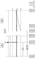
도 3 내지 도 6은 본 발명의 제1 실시 예에 따른 동력전달장치의 모드별 레버 해석법으로 설명하기 위한 도면이다.FIGS. 3 to 6 are views for explaining the lever-by-mode analysis method of the power transmitting apparatus according to the first embodiment of the present invention.
도 3 내지 도 6을 참조하면, 제1 유성기어세트(PG1)의 3개의 세로선은 좌측으로부터 제1, 제2, 제3 회전요소(N1)(N2)(N3)로 설정되며, 중간의 가로선은 회전속도 "0"를 나타내며, 상측의 가로선은 회전속도 "1.0" 즉, 입력축(IS)의 회전속도를 "1.0"이라고 가정했을 때를 나타내고, 하측의 가로선은 회전속도 "-1.0"을 나타낸다.3 to 6, three vertical lines of the first planetary gear set PG1 are set to the first, second and third rotary elements N1, N2 and N3 from the left side, The upper horizontal line represents the rotational speed "1.0 ", that is, the rotational speed of the input shaft IS is" 1.0 ", and the lower horizontal line represents the rotational speed "-1.0 & .
제2 유성기어세트(PG2)의 3개의 세로선은 좌측으로부터 제6, 제5, 제4 회전요소(N6)(N5)(N4)로 설정되며, 중간의 가로선은 회전속도 "0"를 나타내며, 상측의 가로선은 회전속도 "1.0" 즉, 입력축(IS)의 회전속도를 "1.0"이라고 가정했을 때를 나타내고, 하측의 가로선은 회전속도 "-1.0"을 나타낸다.The three vertical lines of the second planetary gear set PG2 are set to the sixth, fifth and fourth rotary elements N6, N5 and N4 from the left, the middle horizontal line represents the rotational speed "0 & The horizontal line on the upper side represents the rotational speed "1.0 ", that is, the rotational speed of the input shaft IS is assumed to be 1.0, and the lower horizontal line represents the rotational speed" -1.0 ".
상기에서 "-"는 엔진의 회전방향과 반대 방향을 의미하며, 입력축(IS)과 제1 유성기어세트(PG1)가 제2 유성기어셋트(PG2)의 연결시 중간에 아이들링 기어(Idling Gear) 없이 제1, 제2 트랜스퍼 기어(TF1)(TF2)를 통해 외접 연결되는 바, 제2 유성기어세트(PG2)의 각 회전요소에 반대방향으로 입력이 이루어지기 때문에 "-" 를 부여한 것이다.The symbol "-" means the direction opposite to the direction of rotation of the engine. The input shaft IS and the first planetary gear set PG1 are connected to an idling gear in the middle of the connection of the second planetary gear set PG2. Quot; - "because the input is made in the opposite direction to each of the rotation elements of the second planetary gear set PG2, and is externally connected via the first and second transfer gears TF1 and TF2.
또한, 상기 제1, 제2 유성기어세트(PG1)(PG2)의 세로선의 간격은 각 기어비(선기어의 잇수/링기어의 잇수)에 따라 설정된다.The pitch of the vertical lines of the first and second planetary gear sets PG1 and PG2 is set in accordance with each gear ratio (the number of teeth of the sun gear / the number of teeth of the ring gear).
[EV 모드 1][EV mode 1]
도 3a는 EV 모드 1에 대한 레버 해석도로서, EV 모드는 엔진이 정지된 상태에서 배터리의 전원을 모터/제너레이터에 공급하여 모터/제너레이터의 동력으로 차량을 주행시키는 모드이다.3A is a lever analysis diagram for
엔진이 정지되어 있기 때문에 연비 향상에 큰 영향을 미치며, 별도의 후진 장치 없이도 후진 주행이 가능하다는 장점이 있다.Since the engine is stopped, it has a great effect on the improvement of the fuel economy and there is an advantage that the vehicle can run backward without a separate reverse device.
이와 같은 EV 모드는 정지 후, 출발 및 저속 주행 시 작동되며, 등판길에서의 밀림방지 또는 빠른 가속을 위하여 동력원이 출력부재보다 빠르게 회전하는 감속 변속비가 요구된다.Such an EV mode is operated at a start and a low speed running after stopping, and a deceleration speed ratio in which the power source rotates faster than the output member is required for prevention of jogging or quick acceleration on the back road.
이러한 조건에서 EV 모드 1에서는 브레이크(BK)의 작동으로 제6 회전요소(N6)가 고정요소로 작동하고, 제2 모터/제너레이터(MG2)를 작동시켜 제4 회전요소(N4)로 입력이 이루어지도록 하면, 제2 유성기어세트(PG2)의 기어비에 따라 제5 회전요소(N5)를 통해 감속 출력이 이루어진다,Under this condition, in the
이때, 제1 유성기어세트(PG1)는 변속에는 관여하지 않으나, 제3 회전요소(N3)가 엔진과 함께 정지된 상태를 유지하고, 제2 회전요소(N2)가 제5 회전요소(N5)와 제1 트랜스퍼 기어(TF1)를 통하여 연결되어 있기 때문에 그 기어비에 따라 제1, 제2 회전요소(N1)(N2)가 공전하게 된다. At this time, the first planetary gear set PG1 does not participate in the shift, but the third rotating element N3 is kept stopped with the engine, and the second rotating element N2 is held in the fifth rotating element N5, And the first transfer gear TF1, the first and second rotary elements N1 and N2 are idled according to the gear ratio.
[EV 모드 2][EV mode 2]
도 3b는 EV 모드 2에 대한 레버 해석도로서, 모터/제너레이터는 회전속도와 토크에 따라 효율이 변하는 특성을 갖는데, 이는 동일한 전류를 공급하더라도 전기 에너지 중에서 회전과 토크의 기계적 에너지로 변환되는 비율이 다르다는 것을 의미한다.3B is a lever analysis diagram for EV mode 2. The motor / generator has a characteristic in which the efficiency changes depending on the rotational speed and the torque. Even if the same current is supplied, the ratio of the rotational energy to the torque mechanical energy It means different.
즉, EV 모드에서 사용되는 배터리의 전류는 엔진에서 연료의 연소에 의하거나 회생 제동에 의해 축적된 에너지로서, 발생된 경로에 관계없이 축적된 에너지를 효율적으로 사용하는 것은 연비 향상에 직결된다.That is, the current of the battery used in the EV mode is the energy accumulated by the combustion of the fuel in the engine or by the regenerative braking, and the efficient use of the stored energy regardless of the generated path leads directly to the improvement of the fuel economy.
이러한 이유로 최근에는 전기 자동차에서도 2단 이상의 변속기를 장착하는 추세이며, 하이브리드 자동차의 EV 모드에서도 2개 이상의 변속단을 갖는 것이 유리하므로, 본 발명이 실시 예에서도 EV 모드 2를 갖도록 하였다.For this reason, it is a recent trend to install two or more speed change transmissions in an electric vehicle, and it is advantageous to have two or more speed change stages even in the EV mode of a hybrid vehicle.
이러한 점을 감안하여 EV 모드 2의 변속과정을 살펴보면, EV 모드 2에서는 상기 EV 모드 1로 주행 중, 차속이 증가하여 제2 모터/제너레이터(MG2)의 효율이 나쁜 지점에서, 브레이크(BK)의 작동을 해제하고, 제1 클러치(CL1)를 작동 제어한다.Taking this into consideration, the shift process of the EV mode 2 will be described. In the EV mode 2, the vehicle speed increases during traveling to the
그러면, 제2 유성기어세트(PG2)의 직결수단인 제1 클러치(CL1)가 작동하므로 제2 유성기어세트(PG2)는 직결의 상태가 되어 전 회전요소(N4)(N5)(N6)가 동일 속도로 회전하면서 제5 회전부재(N5)를 통해 증속 출력이 이루어진다.Then, the first clutch CL1, which is a direct coupling means of the second planetary gear set PG2, is operated, so that the second planetary gear set PG2 is brought into a direct coupling state and the front rotation elements N4, N5, An increased speed output is made through the fifth rotary member N5 while rotating at the same speed.
이때, 제1 유성기어세트(PG1)는 상기 EV 모드 1에서와 같이 엔진이 정지된 상태에서 회전하되, 제5 회전요소(N5)가 증속된 만큼 제1, 제2 회전요소(N1)(N2)가 증속 회전한다. At this time, the first planetary gear set PG1 rotates while the engine is stopped as in the
[하이브리드 입력분기 모드 1][Hybrid input branch mode 1]
도 4a는 하이브리드 입력분기 모드 1에 대한 레버 해석도로서, 하이브리드 입력분기 모드에서는 엔진의 동력이 기계적 경로와 전기적 경로를 통해 출력부재로 전달되며, 이러한 동력 분배는 유성기어세트에 의하여 이루어지고, 상기 유성기어세트에 연결된 엔진과 모터/제너레이터는 차속에 관계 없이 회전속도를 임의로 조절할 수 있게 때문에 전자식 무단 변속기 역할을 수행한다.4A is a lever analysis diagram for the hybrid
따라서 기존 변속기가 주어진 차속에 대하여 엔진 속도와 토크가 고정되는데 반하여, 전자식 무단 변속기는 엔진 속도와 토크를 자유롭게 변경할 수 있기 때문에 엔진의 운전 효율을 극대화시킬 수 있으며, 연비 향상을 도모할 수 있다.Therefore, while the engine speed and torque are fixed for a given vehicle speed of the conventional transmission, the electronic stepless transmission can freely change the engine speed and torque, thereby maximizing the operation efficiency of the engine and improving the fuel efficiency.
이러한 점을 감안하여 하이브리드 입력분기 모드 1의 변속과정을 살펴보면, 상기 EV 모드에서는 제2 회전요소(N2)가 제1 트랜스퍼 기어(TF1)에 의하여 속도가 구속되어 있을 뿐, 제1, 제3 회전요소(N1)(N3)는 회전이 자유롭다.In this case, the speed of the second rotary element N2 is restricted by the first transfer gear TF1, and the first and third rotations N1, Elements N1 and N3 are free to rotate.
따라서 상기의 상태에서, 제1 모터 제너레이터(MG1)를 이용하여 엔진(ENG)을 작동시킨 후에는 차속에 관계 없이 엔진(ENG)과 제1 모터 제너레이터(MG1)의 속도를 제어할 수 있다.Therefore, in the above state, after the engine ENG is operated using the first motor generator MG1, the speeds of the engine ENG and the first motor generator MG1 can be controlled regardless of the vehicle speed.
이에 따라 엔진(ENG)과 제1 모터/제너레이터(MG1)를 필요에 따라 무단으로 제어하면, 엔진과 제1 모터/제너레이터(MG1)의 토크 합이 제1 트랜스퍼 기어(TF1)를 통해 출력요소인 제5 회전요소(N5)로 전달되어 높은 구동력을 발생시킬 수 있다. Thus, if the engine ENG and the first motor / generator MG1 are controlled as needed, the torque sum of the engine and the first motor / generator MG1 is transmitted through the first transfer gear TF1 to the output element And is transmitted to the fifth rotating element N5 to generate a high driving force.
이때, 제2 유성기어세트(PG2)는 브레이크(BK)가 작동되면서 제6 회전요소(N6)가 고정요소로 작동하여 제5 회전요소(N5)를 통해 출력이 이루어지며, 제4 회전요소(N4)는 제2모터/제너레이터(MG2)의 동력을 받아 회전하게 된다.At this time, the second planetary gear set PG2 is operated by the brake BK and the sixth rotary element N6 operates as a fixed element and is output through the fifth rotary element N5, and the fourth rotary element N4 are rotated by the power of the second motor / generator MG2.
이와 같이 하이브리드 입력분기 모드 1에서는 엔진(ENG)과 제1 모터/제너레이터(MG1)를 필요에 따라 무단 제어할 수 있기 때문에 연비와 동력성능 측면에서 매우 우수한 성능을 발휘할 수 있다.In this way, in the hybrid
[하이브리드 입력분기 모드 2][Hybrid input branch mode 2]
도 4b는 하이브리드 입력분기 모드 2에 대한 레버 해석도로서, 하이브리드 입력 분기 모드 2에서는 상기 하이브리드 입력분기 모드 1로 주행 중, 차속이 증가하면, 제1 유성기어세트(PG1)의 각 회전요소에 대한 회전속도 수준을 전체적으로 저하시키기 위하여 브레이크(BK)의 작동을 해제하고, 제1 클러치(CL1)를 작동 제어한다.FIG. 4B is a lever analysis diagram for the hybrid input branch mode 2. In the hybrid input branch mode 2, when the vehicle speed increases during traveling to the hybrid
그러면, 제2 유성기어세트(PG2)의 직결수단인 제1 클러치(CL1)가 작동하므로 제2 유성기어세트(PG2)는 직결의 상태가 되어 전 회전요소(N4)(N5)(N6)가 동일 속도로 회전하면서 제5 회전부재(N5)를 통해 증속 출력이 이루어진다.Then, the first clutch CL1, which is a direct coupling means of the second planetary gear set PG2, is operated, so that the second planetary gear set PG2 is brought into a direct coupling state and the front rotation elements N4, N5, An increased speed output is made through the fifth rotary member N5 while rotating at the same speed.
이와 같이 하이브리드 입력분기 모드 2에서는 하이브리드 입력분기 모드 1과 마찬가지로 엔진(ENG)과 제1 모터/제너레이터(MG1)를 필요에 따라 무단 제어할 수 있기 때문에 연비와 동력성능 측면에서 매우 우수한 성능을 발휘할 수 있다.As described above, in the hybrid input branch mode 2, since the engine ENG and the first motor / generator MG1 can be controlled as needed in the same manner as in the hybrid
[하이브리드 복합분기 모드][Hybrid compound branching mode]
도 5는 하이브리드 복합분기 모드에 대한 레버 해석도로서, 상기 하이브리드 입력분기 모드에서는 출력부재에 연결된 모터/제너레이터의 회전속도가 차속에 구속되어 있어 모터/제너레이터의 효율적인 운용이 어려울 뿐 만 아니라 용량을 줄이기도 어렵다.5 is a lever analysis diagram for hybrid hybrid branching mode. In the hybrid input branching mode, the rotational speed of the motor / generator connected to the output member is constrained to the vehicle speed, which makes it difficult to efficiently operate the motor / It is difficult.
특히, 차속이 높아서 차속에 구속된 모터/제너레이터의 회전속도가 높을 때에는 모터/제너레이터의 효율이 악화되기 때문에 최적의 연비를 구현할 수 없다.Particularly, when the vehicle speed is high and the rotational speed of the motor / generator constrained to the vehicle speed is high, the efficiency of the motor / generator deteriorates, so that the optimum fuel efficiency can not be realized.
이러한 조건에서 엔진(ENG)이 연결된 제1 유성기어세트(PG1)와 출력축이 연결된 제2 유성기어세트(PG2)의 각기 다른 두 요소를 서로 결합시켜 엔진(ENG)과 2개의 모터/제너레이터(MG1,MG2)를 모두 차속과 관계 없이 회전속도를 제어할 수 있도록 하면, 다시 한번 무단 변속기 기능이 작동하여 연비 향상을 도모할 수 있다.Under these conditions, the engine ENG and the two motor / generators MG1 and MG2 are coupled to each other by coupling two different elements of the first planetary gear set PG1 connected to the engine ENG and the second planetary gear set PG2 connected to the output shaft, And MG2 can be controlled irrespective of the vehicle speed, the fuel economy can be improved by operating the continuously variable transmission once more.
이에 따라, 제2 클러치(CL2)를 작동시키면, 제2 트랜스퍼 기어(TF2)를 통해 제3 회전요소(N3)와 제4 회전요소(N4)가 연결되므로 상호 속도와 토크의 구속을 받게 된다.Accordingly, when the second clutch CL2 is operated, the third rotary element N3 and the fourth rotary element N4 are connected via the second transfer gear TF2, so that the speed and torque are constrained to each other.
그리고 제1, 제2 모터/제너레이터(MG1)(MG2)의 전기 에너지 평형이 이루어져야 함으로써, 하이브리드 복합분기 모드에서는 제1, 제2 유성기어세트(PG1)(PG2)의 모든 회전요소가 속도와 토크에 대하여 서로 연관을 가지면서 전기 무단 변속기 기능을 수행하게 된다.In addition, in the hybrid hybrid branching mode, all the rotational elements of the first and second planetary gear sets PG1 and PG2 must be balanced by the electric energy balance of the first and second motor / generators MG1 and MG2, And functions as an electrically controlled continuously variable transmission.
상기와 같은 하이브리드 복합분기는 하이브리드 입력분기 모드 1과 하이브리드 입력분기 모드 2에서 변환이 가능하며, 상기 하이브리드 입력분기 모드 1과 하이브리드 입력분기 모드 2에서 하이브리드 복합분기 모드로 변환하고자 할 때에는 엔진(ENG)과 제1 모터/제너레이터(MG1)를 제어하여 제2 클러치(CL2)의 동기가 이루어지도록 한 후에 제2 클러치(CL2)를 작동 제어한다.The hybrid hybrid branch may be switched between the hybrid
그리고 하이브리드 입력분기 모드 1에서 하이브리드 복합분기 모드로 변환할 때에는 제2 클러치(CL2)를 작동 제어하면서 브레이크(B2)를 해제하고, 하이브리드 입력분기 모드 2에서 하이브리드 복합분기 모드로 변환할 때에는 제2 클러치(CL2)를 작동 제어하면서 제1 클러치(CL1)의 작동을 해제하면 된다.When switching from the hybrid
이러한 하이브리드 복합분기 모드에서는 제6 회전요소(N6)가 토크를 받을 수 없기 때문에 제4 회전요소(N4)와 제5 회전요소(N5)에 입력되는 토크의 합이 각각 "0"이 되어야 한다.In this hybrid hybrid branching mode, since the sixth rotary element N6 can not receive the torque, the sum of the torques input to the fourth rotary element N4 and the fifth rotary element N5 must be "0 ".
즉, 상기 제4 회전요소(N4)는 제2 모터/제너레이터(MG2)의 토크와 제2 트랜스퍼 기어(TF2)로부터 입력되는 외부 토크가 평형을 이루게 된다.That is, the torque of the second motor / generator MG2 and the external torque input from the second transfer gear TF2 are balanced in the fourth rotary element N4.
또한, 상기 제5 회전요소(N5)는 주행 저항으로 인하여 입력되는 토크와 제1 트랜스퍼 기어(TF1)로부터 입력되는 외부 토크가 평형을 이루게 된다.In addition, the fifth rotary element N5 is balanced between the torque input due to the running resistance and the external torque input from the first transfer gear TF1.
[엔진 모드 1][Engine mode 1]
도 6a는 엔진 모드 1에 대한 레버 해석도로서, 하이브리드 자동차의 연비 향상을 위한 핵심 기술은 제동 에너지의 회수 및 재사용과 엔진 운전점의 자유로운 제어라고 할 수 있다.6A is a lever analysis diagram for
그리고 엔진 운전점의 제어에는 엔진의 기계적 에너지가 모터/제너레이터에서 전기적 에너지로 변환되는 과정과, 모터/제너레이터의 전기적 에너지가 모터/제너레이터에서 다시 기계적 에너지로 변환되는 두 번의 에너지 변환과정을 동반한다.Control of the engine starting point is accompanied by two energy conversion processes in which the mechanical energy of the engine is converted into electrical energy from the motor / generator and the electrical energy of the motor / generator is converted back to mechanical energy in the motor / generator.
이러한 에너지 변환 역시 입력된 모든 에너지가 출력되지 않고 중간에 손실이 발생한다. This energy conversion also does not output all the input energy and causes a loss in the middle.
따라서 어떤 운전 조건에서는 하이브리드 모드보다 오히려 엔진만으로 구동되는 엔진 모드에서의 연비가 우수할 수 있으므로 본 발명의 실시 예에서는 2개의 엔진 모드를 제공한다.Therefore, since the fuel efficiency in the engine mode driven by only the engine can be excellent rather than the hybrid mode under certain operating conditions, the embodiment of the present invention provides two engine modes.
즉, 엔진 모드 1에서는 제2 클러치(CL2)와 브레이크(BK)를 체결하면, 엔진 속도에 따라 제2 트랜스퍼 기어(TF2)를 통해 제4 회전요소(N4)가 반대방향으로 회전하고, 제6 회전요소(N6)가 정지하기 때문에 감속 변속비가 형성된다.That is, in the
이때 제1, 제2 모터/제너레이터(MG1)(MG2)는 토크를 제공할 필요가 없기 때문에 순수하게 엔진(ENG)의 동력만으로 차량이 구동되는 엔진 모드 1가 성립된다.At this time, since the first and second motor / generators MG1 and MG2 need not provide the torque, the
즉, 엔진(ENG)의 토크는 제2 트랜스퍼 기어(TF2)를 통하여 기어비에 따라 제4 회전요소(N4)에 전달되고, 모든 주행 저항은 제5 회전요소(N5)로 전달하게 된다. That is, the torque of the engine ENG is transmitted to the fourth rotary element N4 through the second transfer gear TF2 in accordance with the gear ratio, and all the traveling resistance is transmitted to the fifth rotary element N5.
그리고 제6 회전요소(N6)는 브레이크(BK)로부터 반시계 방향의 토크를 받으면서 엔진 모드 1이 성립되는 것이다.The sixth rotation element N6 is set to the
[엔진 모드 2][Engine Mode 2]
도 6b는 엔진 모드 2에 대한 레버 해석도로서, 엔진 모드 2에서는 상기 엔진 모드 1로 주행 중, 차속이 증가하면, 제1 클러치(CL1)과 제2 클러치(C2)를 작동 제어한다.6B is an explanatory diagram of a lever for engine mode 2. In engine mode 2, when the vehicle speed is increased during running in
그러면, 엔진 속도에 의해 제2 트랜스퍼 기어(TF2)의 기어비에 따라 제4 회전요소(N4)가 반시계 방향으로 회전하고, 제1 클러치(CL1)의 작동에 의하여 제2 유성기어세트(PG2)의 전 회전요소(N4)(N5)(N6)가 일체로 회전한다.Then, the fourth rotary element N4 rotates counterclockwise in accordance with the gear ratio of the second transfer gear TF2 by the engine speed, and the second planetary gear set PG2 is rotated by the operation of the first clutch CL1, N4, N5, and N6 rotate integrally with each other.
이때 엔진(ENG) 보다 제2 모터/제너레이터(MG2)가 빨리 회전할 수 있도록 제2 트랜스퍼 기어(TF2)의 기어비가 설정되어 있기 때문에 증속 변속비가 형성되며, 제1, 제2 모터/제너레이터(MG1)(MG2)는 토크를 제공할 필요가 없기 때문에 순수하게 엔진(ENG)의 동력만으로 차량이 구동되는 엔진 모드 2가 성립된다.At this time, since the gear ratio of the second transfer gear TF2 is set so that the second motor / generator MG2 can rotate faster than the engine ENG, a speed change speed ratio is formed, and the first and second motor / ) MG2 does not need to provide torque, engine mode 2 is established in which the vehicle is driven only by the power of the engine ENG purely.
이상에서와 같이 본 발명의 제1 실시 예에 의하면, 전체적인 구성에 있어서, 2개의 유성기어세트(PG1)(PG2)와 외접기어인 2개의 트랜스퍼 기어(TF1)(TF2), 그리고 3개의 마찰요소(CL1)(CL2)(BK)와 2개의 모터/제너레이터(MG1)(MG2)의 조합으로 2개의 EV 모드와, 2개의 하이브리드 입력분기 모드와, 1개의 하이브리드 복합분기 모드, 2개의 엔진 모드를 구현할 수 있다.As described above, according to the first embodiment of the present invention, in the overall configuration, two planetary gear sets PG1 and PG2, two transfer gears TF1 and TF2 as external gears, and three friction elements Two EV modes, two hybrid input branch modes, one hybrid compound branch mode, and two engine modes are selected by a combination of the first motor / generator CL1 (CL2) (BK) and two motor / generators MG1 Can be implemented.
또한, 유성기어세트 외에 외접 기어인 2개의 트랜스퍼 기어를 적용함으로써, 자유로운 기어 잇수 변경으로 차량별 최적의 기어비를 설정할 수 있으며, 요구 성능 조건에 맞도록 기어 변경이 가능하여 발진 성능을 향상시킬 수 있다.Furthermore, by applying two transfer gears, which are external gears, in addition to the planetary gear set, it is possible to set the optimum gear ratio for each vehicle by changing the number of gear teeth freely and it is possible to change gears to meet required performance conditions, .
그리고 작용 효과면에 있어서, WOT(Wide Open Throttle)발진시 충분한 동력 성능을 제공하여 엔진 모드로의 변환을 억제하고, 하이브리드 입력분기 모드와 복합분기 모드의 변환 시 엔진의 최대 동력을 사용할 수 있다.In terms of the operation effect, it is possible to provide sufficient power performance in the WOT (Wide Open Throttle) oscillation to suppress the conversion to the engine mode, and to use the maximum power of the engine in the hybrid input branch mode and the hybrid branch mode conversion.
또한, 엔진 동력을 분기함에 있어서, 기계적 동력전달경로의 비중을 높여 전기 부하를 줄이고 엔진의 최대 동력을 사용할 수 있도록 함으로써, 발진 시 엔진 모드를 대체하여 모드 변환 횟수를 줄이며, 모드 변환시 모든 회전요소의 회전수 변화를 최소화할 수 있다.In addition, in branching the engine power, the weight of the mechanical power transmission path is increased to reduce the electric load and to use the maximum power of the engine, thereby reducing the frequency of mode conversion by replacing the engine mode at the time of oscillation, The change in the number of revolutions can be minimized.
그리고 엔진 모드를 제공하여 고속 주행 시 모터/제너레이터의 전기 부하 없이 주행이 가능하도록 하여 연비를 향상시킬 수 있다.And engine mode is provided to enable driving without electric load of motor / generator during high speed driving, thereby improving fuel efficiency.
도 7은 본 발명의 제2 실시 예에 따른 동력전달장치의 구성도이다.7 is a configuration diagram of a power transmitting apparatus according to a second embodiment of the present invention.
도 7을 참조하면, 제1 실시 예에서는 제2 유성기어세트(PG2)의 직결수단인 제1 클러치(CLl)를 제4 회전요소(N4)와 제5 회전요소(N5) 사이에 배치하고 있으나, 제2 실시 예에서는 제1 클러치(CL1)를 제4 회전요소(N4)와 제6 회전요소(N6) 사이에 배치한 것이다.Referring to Fig. 7, in the first embodiment, the first clutch CL1, which is the direct coupling means of the second planetary gearset PG2, is disposed between the fourth rotary element N4 and the fifth rotary element N5 . In the second embodiment, the first clutch CL1 is disposed between the fourth rotary element N4 and the sixth rotary element N6.
이러한 제2 실시 예의 경우, 상기 제1 실시 예와 비교하여 제1 클러치(CL1)의 배치 위치만 다를 뿐, 구성 및 작용 효과가 동일하므로 상세한 설명은 생략한다.The second embodiment differs from the first embodiment only in the arrangement position of the first clutch CL1, and the structure and operation effects are the same, and a detailed description thereof will be omitted.
도 8은 본 발명의 제3 실시 예에 따른 동력전달장치의 구성도이다.8 is a configuration diagram of a power transmitting apparatus according to a third embodiment of the present invention.
도 8을 참조하면, 제1 실시 예에서는 제2 유성기어세트(PG2)의 직결수단인 제1 클러치(CLl)를 제4 회전요소(N4)와 제5 회전요소(N5) 사이에 배치하고 있으나, 제3 실시 예에서는 제1 클러치(CL1)를 제5 회전요소(N5)와 제6 회전요소(N6) 사이에 배치한 것이다.Referring to FIG. 8, in the first embodiment, the first clutch CL1, which is the direct coupling means of the second planetary gear set PG2, is disposed between the fourth rotary element N4 and the fifth rotary element N5 . In the third embodiment, the first clutch CL1 is disposed between the fifth rotating element N5 and the sixth rotating element N6.
이러한 제3 실시 예의 경우, 상기 제1 실시 예와 비교하여 제1 클러치(CL1)의 배치 위치만 다를 뿐, 구성 및 작용 효과가 동일하므로 상세한 설명은 생략한다.The third embodiment differs from the first embodiment only in the arrangement position of the first clutch CL1, and the structure and operation effects are the same, so a detailed description thereof will be omitted.
도 9는 본 발명의 제4 실시 예에 따른 동력전달장치의 구성도이다.9 is a configuration diagram of a power transmitting apparatus according to a fourth embodiment of the present invention.
도 9를 참조하면, 제1 실시 예에서는 제2 클러치(CL2)를 입력축(IS)을 포함하는 제3 회전요소(N3)와 제2 트랜스퍼 기어(TF2) 사이에 배치하고 있으나, 제4 실시 예에서는 상기 제2 클러치(CL2)를 제2 트랜스퍼 기어(TF2)와 제4 회전요소(N4) 사이에 배치한 것이다.9, in the first embodiment, the second clutch CL2 is disposed between the third rotary element N3 including the input shaft IS and the second transfer gear TF2. However, in the fourth embodiment The second clutch CL2 is disposed between the second transfer gear TF2 and the fourth rotary element N4.
이러한 제4 실시 예의 경우, 상기 제1 실시 예와 비교하여 제2 클러치(CL2)의 배치 위치만 다를 뿐 구성 및 작용 효과가 동일하므로 상세한 설명은 생략한다.The fourth embodiment differs from the first embodiment only in the arrangement position of the second clutch CL2, but the structure and operation effects are the same, and a detailed description thereof will be omitted.
도 10은 본 발명의 제5 실시 예에 따른 동력전달장치의 구성도이다.10 is a configuration diagram of a power transmitting apparatus according to a fifth embodiment of the present invention.
도 10을 참조하면, 제1 실시 예에서는 제1 유성기어세트(PG1)를 싱글 피니언 유성기어세트로 구성하고 있으나, 제5 실시 예에서는 제1 유성기어세트(PG1)를 더블 피니언 유성기어세트로 구성한 것이다.Referring to FIG. 10, in the first embodiment, the first planetary gear set PG1 is composed of a single pinion planetary gear set. In the fifth embodiment, the first planetary gear set PG1 is a double pinion planetary gear set Respectively.
이에 따라 제1 회전요소(N1)가 제1 선기어(S1), 제2 회전요소(N2)가 제1 링기어(R1), 제3 회전요소(N3)가 제1 유성캐리어(PC1)로 구성된다.The first rotating element N1 is constituted by the first sun gear S1 and the second rotating element N2 is constituted by the first ring gear R1 and the third rotating element N3 is constituted by the first planetary carrier PC1 do.
이러한 제5 실시 예의 경우, 상기 제1 실시 예와 비교하여 제2, 제3 회전요소(N2)(N3)의 구성만 다를 뿐 작동 효과가 동일하므로 상세한 설명은 생략한다.In this fifth embodiment, the second and third rotary elements N2 and N3 are different from the first embodiment only in terms of operation, and a detailed description thereof will be omitted.
도 11은 본 발명의 제6 실시 예에 따른 동력전달장치의 구성도이다.11 is a configuration diagram of a power transmitting apparatus according to a sixth embodiment of the present invention.
도 11을 참조하면, 제1 실시 예에서는 제2 유성기어세트(PG2)를 싱글 피니언 유성기어세트로 구성하고 있으나, 제6 실시 예에서는 제2 유성기어세트(PG2)를 더블 피니언 유성기어세트로 구성한 것이다.11, in the first embodiment, the second planetary gear set PG2 is composed of a single pinion planetary gear set, but in the sixth embodiment, the second planetary gear set PG2 is a double pinion planetary gear set Respectively.
이에 따라 제4 회전요소(N4)가 제2 선기어(S2), 제5 회전요소(N5)가 제2 링기어(R2), 제6 회전요소(N6)가 제2 유성캐리어(PC2)로 구성된다.Thus, the fourth rotating element N4 is constituted by the second sun gear S2, the fifth rotating element N5 is constituted by the second ring gear R2 and the sixth rotating element N6 is constituted by the second planetary carrier PC2 do.
이러한 제6 실시 예의 경우, 상기 제1 실시 예와 비교하여 제5, 제6 회전요소(N5)(N6)의 구성만 다를 뿐 작용 효과가 동일하므로 상세한 설명은 생략한다.In this sixth embodiment, the fifth and sixth rotary elements N5 and N6 are different from the first embodiment only in terms of the operation and effect, so that detailed description is omitted.
이상으로 본 발명의 바람직한 실시 예들을 설명하였으나, 본 발명은 상기 실시 예에 한정되지 아니하며, 본 발명의 실시 예로부터 당해 발명이 속하는 기술분야에서 통상의 지식을 가진 자에 의해 용이하게 변경되어 균등하다고 인정되는 범위의 모든 변경을 포함한다.While the present invention has been particularly shown and described with reference to exemplary embodiments thereof, it is clearly understood that the same is by way of illustration and example only and is not to be taken by way of limitation, Includes all changes to the scope permitted.
BK... 브레이크
CL1,CL2... 제1, 제2 클러치
IS... 입력축
OS... 출력축
MG1, MG2... 제1, 제2 모터/제너레이터
PG1,PG2... 제1, 제2 유성기어세트
S1,S2... 제1, 제2 선기어
PC1,PC2... 제1, 제2 유성캐리어
R1,R2... 제1, 제2 링기어
OG... 출력기어BK ... Brake
CL1, CL2 ... First and second clutches
IS ... input shaft
OS ... Output shaft
MG1, MG2 ... First and second motor / generators
PG1, PG2 ... First and second planetary gear sets
S1, S2 ... First and second sun gear
PC1, PC2 ... First and second planetary carriers
R1, R2 ... First and second ring gears
OG ... output gear
Claims (31)
상기 입력축과 소정의 간격을 두고 평행하게 배치되는 출력축;
상기 입력축상에 배치되어 제1 회전요소가 제1 모터/제너레이터와 연결되고, 제2 회전요소가 출력요소로 작동하며, 제3 회전요소가 상기 입력축과 직접 연결됨과 동시에 제2 모터/제네레이터와 연결되는 제1 유성기어세트;
상기 출력축상에 배치되어 상기 제4 회전요소가 선택적으로 상기 제3 회전요소와 외접 기어 연결되고, 제5 회전요소가 상기 제2 회전요소와 외접 기어 연결됨과 동시에 출력축과 연결되며, 제6 회전요소가 변속기 하우징과 선택적으로 연결되는 제2 유성기어세트;
상기 제2 유성기어세트의 3개의 회전요소 중, 2개의 회전요소를 선택적으로 연결하는 직결수단;
상기 외접 기어 연결부에 배치되는 트랜스퍼 기어;
상기 선택적 연결부에 배치되는 마찰요소;
를 포함하여 이루어지는 하이브리드 자동차의 동력전달장치. An input shaft through which the power of the engine is input;
An output shaft disposed parallel to the input shaft at a predetermined interval;
A first rotary element is connected to the first motor / generator, a second rotary element is operated as an output element, a third rotary element is directly connected to the input shaft, and the second rotary element is connected to the second motor / A first planetary gear set;
The fourth rotary element is selectively connected to the third rotary element and the external gear is connected to the output shaft, the fifth rotary element is connected to the external gear and is connected to the output shaft, A second planetary gear set selectively connected to the transmission housing;
A direct connection means for selectively connecting two rotary elements among the three rotary elements of the second planetary gear set;
A transfer gear disposed at the external gear connecting portion;
A friction element disposed at the optional connection;
And a power transmission device for the hybrid vehicle.
상기 제1 유성기어세트는 싱글 피니언 유성기어세트로서, 제1 회전요소는 제1 선기어, 제2 회전요소는 제1 유성캐리어, 제3 회전요소는 제1 링기어로 이루어지며,
상기 제2 유성기어세트는 싱글 피니언 유성기어세트로서, 제4 회전요소는 제2 선기어, 제5 회전요소는 제2 유성캐리어, 제6 회전요소는 제2 링기어로 이루어지는 하이브리드 자동차의 동력전달장치.The method according to claim 1,
Wherein the first planetary gear set is a single pinion planetary gear set, the first rotation element comprises a first sun gear, the second rotation element comprises a first planet carrier, and the third rotation element comprises a first ring gear,
Wherein the second planetary gear set is a single pinion planetary gear set, the fourth rotary element comprises a second sun gear, the fifth rotary element comprises a second planetary carrier, and the sixth rotary element comprises a second ring gear. .
상기 제1 유성기어세트는 더블 피니언 유성기어세트로서, 제1 회전요소는 제1 선기어, 제2 회전요소는 제1 링기어, 제3 회전요소는 제1 유성캐리어로 이루어지며,
상기 제2 유성기어세트는 싱글 피니언 유성기어세트로서, 제4 회전요소는 제2 선기어, 제5 회전요소는 제2 유성캐리어, 제6 회전요소는 제2 링기어로 이루어지는 하이브리드 자동차의 동력전달장치.The method according to claim 1,
Wherein the first planetary gear set is a double pinion planetary gear set, wherein the first rotation element comprises a first sun gear, the second rotation element comprises a first ring gear, and the third rotation element comprises a first planet carrier,
Wherein the second planetary gear set is a single pinion planetary gear set, the fourth rotary element comprises a second sun gear, the fifth rotary element comprises a second planetary carrier, and the sixth rotary element comprises a second ring gear. .
상기 제1 유성기어세트는 싱글 피니언 유성기어세트로서, 제1 회전요소는 제1 선기어, 제2 회전요소는 제1 유성캐리어, 제3 회전요소는 제1 링기어로 이루어지며,
상기 제2 유성기어세트는 더블 피니언 유성기어세트로서, 제4 회전요소는 제2 선기어, 제5 회전요소는 제2 링기어, 제6 회전요소는 제2 유성캐리어로 이루어지는 하이브리드 자동차의 동력전달장치.The method according to claim 1,
Wherein the first planetary gear set is a single pinion planetary gear set, the first rotation element comprises a first sun gear, the second rotation element comprises a first planet carrier, and the third rotation element comprises a first ring gear,
The second planetary gear set is a double pinion planetary gear set, the fourth rotary element is composed of a second sun gear, the fifth rotary element is a second ring gear, and the sixth rotary element is a second planetary carrier. .
상기 직결수단은
제4 회전요소와 제5 회전요소 사이에 배치되는 제1 클러치(CL1)로 이루어지는 하이브리드 자동차의 동력전달장치.The method according to claim 1,
The direct-
And a first clutch (CL1) disposed between the fourth rotating element and the fifth rotating element.
상기 직결수단은
제4 회전요소와 제6 회전요소 사이에 배치되는 제1 클러치(CL1)로 이루어지는 하이브리드 자동차의 동력전달장치.The method according to claim 1,
The direct-
And a first clutch (CL1) disposed between the fourth rotating element and the sixth rotating element.
상기 직결수단은
제5 회전요소와 제6 회전요소 사이에 배치되는 제1 클러치(CL1)로 이루어지는 하이브리드 자동차의 동력전달장치.The method according to claim 1,
The direct-
And a first clutch (CL1) disposed between the fifth rotating element and the sixth rotating element.
상기 트랜스퍼 기어는
제2 회전요소와 제5 회전요소 사이에 배치되는 제1 트랜스퍼 기어;
제3 회전요소와 제4 회전요소 사이에 배치되는 제2 트랜스퍼 기어를 포함하는 하이브리드 자동차의 동력전달장치.The method according to claim 1,
The transfer gear
A first transfer gear disposed between the second rotating element and the fifth rotating element;
And a second transfer gear disposed between the third rotating element and the fourth rotating element.
상기 마찰요소는
제6 회전요소와 변속기 하우징 사이에 배치되는 브레이크;
제3 회전요소와 제2 트랜스퍼 기어 사이에 배치되는 제2 클러치를 포함하는 하이브리드 자동차의 동력전달장치.The method according to claim 1,
The friction element
A brake disposed between the sixth rotating element and the transmission housing;
And a second clutch disposed between the third rotary element and the second transfer gear.
상기 마찰요소는
상기 제6 회전요소와 변속기 하우징 사이에 배치되는 브레이크;
상기 제4 회전요소와 제2 트랜스퍼 기어 사이에 배치되는 제2 클러치를 포함하는 하이브리드 자동차의 동력 전달장치.The method according to claim 1,
The friction element
A brake disposed between the sixth rotating element and the transmission housing;
And a second clutch disposed between the fourth rotary element and the second transfer gear.
상기 직결수단을 형성하는 제1 클러치와, 상기 마찰요소를 형성하는 브레이크 및 제2 클러치는
EV 모드 1에서 브레이크가 작동되고,
EV 모드 2에서 제1 클러치가 작동되며,
하이브리드 입력분기 모드 1에서 브레이크가 작동되고,
하이브리드 입력분기 모드 2에서 제1 클러치가 작동되며,
하이브리드 복합분기 모드에서 제2 클러치가 작동되고,
엔진 모드 1에서 제2 클러치와 브레이크가 동시에 작동되며,
엔진 모드 2에서 제1 클러치와 제2 클러치가 동시에 작동되는 하이브리드 자동차의 동력전달장치.The method according to claim 1,
A first clutch that forms the direct coupling means, and a brake and a second clutch which form the friction element
The brake is activated in EV mode 1,
The first clutch is operated in the EV mode 2,
The brake is activated in hybrid input branch mode 1,
The first clutch is operated in the hybrid input branch mode 2,
The second clutch is operated in the hybrid hybrid branch mode,
In the engine mode 1, the second clutch and the brake are operated simultaneously,
In the engine mode 2, the first clutch and the second clutch are operated simultaneously.
상기 입력축과 소정의 간격을 두고 평행하게 배치되는 출력축;
상기 입력축상에 배치되어 제1 회전요소가 제1 모터/제너레이터와 연결되고, 제2 회전요소가 출력요소로 작동하며, 제3 회전요소가 상기 입력축과 직접 연결됨과 동시에 제2 모터/제네레이터와 연결되는 제1 유성기어세트;
상기 출력축상에 배치되어 상기 제4 회전요소가 선택적으로 상기 제3 회전요소와 외접 기어 연결되고, 제5 회전요소가 상기 제2 회전요소와 외접 기어 연결됨과 동시에 출력축과 연결되며, 제6 회전요소가 변속기 하우징과 선택적으로 연결되는 제2 유성기어세트;
상기 제4 회전요소와 제5 회전요소 사이에 배치되는 직결수단인 제1 클러치(CL1);
상기 제2 회전요소와 제5 회전요소 사이에 배치되는 외접 기어인 제1 트랜스퍼 기어와;
상기 제3 회전요소와 제4 회전요소 사이에 배치되는 외접 기어인 제2 트랜스퍼 기어와;
상기 제6 회전요소와 변속기 하우징 사이에 배치되는 브레이크;
상기 제3 회전요소와 제2 트랜스퍼 기어 사이에 배치되는 제2 클러치;
를 포함하여 이루어지는 하이브리드 자동차의 동력전달장치. An input shaft through which the power of the engine is input;
An output shaft disposed parallel to the input shaft at a predetermined interval;
A first rotary element is connected to the first motor / generator, a second rotary element is operated as an output element, a third rotary element is directly connected to the input shaft, and the second rotary element is connected to the second motor / A first planetary gear set;
The fourth rotary element is selectively connected to the third rotary element and the external gear is connected to the output shaft, the fifth rotary element is connected to the external gear and is connected to the output shaft, A second planetary gear set selectively connected to the transmission housing;
A first clutch CL1 as a direct coupling means disposed between the fourth rotary element and the fifth rotary element;
A first transfer gear which is an external gear disposed between the second rotary element and the fifth rotary element;
A second transfer gear which is an external gear disposed between the third rotating element and the fourth rotating element;
A brake disposed between the sixth rotating element and the transmission housing;
A second clutch disposed between the third rotary element and the second transfer gear;
And a power transmission device for the hybrid vehicle.
상기 제1 유성기어세트는 싱글 피니언 유성기어세트로서, 제1 회전요소는 제1 선기어, 제2 회전요소는 제1 유성캐리어, 제3 회전요소는 제1 링기어로 이루어지며,
상기 제2 유성기어세트는 싱글 피니언 유성기어세트로서, 제4 회전요소는 제2 선기어, 제5 회전요소는 제2 유성캐리어, 제6 회전요소는 제2 링기어로 이루어지는 하이브리드 자동차의 동력전달장치.13. The method of claim 12,
Wherein the first planetary gear set is a single pinion planetary gear set, the first rotation element comprises a first sun gear, the second rotation element comprises a first planet carrier, and the third rotation element comprises a first ring gear,
Wherein the second planetary gear set is a single pinion planetary gear set, the fourth rotary element comprises a second sun gear, the fifth rotary element comprises a second planetary carrier, and the sixth rotary element comprises a second ring gear. .
상기 제1 유성기어세트는 더블 피니언 유성기어세트로서, 제1 회전요소는 제1 선기어, 제2 회전요소는 제1 링기어, 제3 회전요소는 제1 유성캐리어로 이루어지며,
상기 제2 유성기어세트는 싱글 피니언 유성기어세트로서, 제4 회전요소는 제2 선기어, 제5 회전요소는 제2 유성캐리어, 제6 회전요소는 제2 링기어로 이루어지는 하이브리드 자동차의 동력전달장치.13. The method of claim 12,
Wherein the first planetary gear set is a double pinion planetary gear set, wherein the first rotation element comprises a first sun gear, the second rotation element comprises a first ring gear, and the third rotation element comprises a first planet carrier,
Wherein the second planetary gear set is a single pinion planetary gear set, the fourth rotary element comprises a second sun gear, the fifth rotary element comprises a second planetary carrier, and the sixth rotary element comprises a second ring gear. .
상기 제1 유성기어세트는 싱글 피니언 유성기어세트로서, 제1 회전요소는 제1 선기어, 제2 회전요소는 제1 유성캐리어, 제3 회전요소는 제1 링기어로 이루어지며,
상기 제2 유성기어세트는 더블 피니언 유성기어세트로서, 제4 회전요소는 제2 선기어, 제5 회전요소는 제2 링기어, 제6 회전요소는 제2 유성캐리어로 이루어지는 하이브리드 자동차의 동력전달장치.13. The method of claim 12,
Wherein the first planetary gear set is a single pinion planetary gear set, the first rotation element comprises a first sun gear, the second rotation element comprises a first planet carrier, and the third rotation element comprises a first ring gear,
The second planetary gear set is a double pinion planetary gear set, the fourth rotary element is composed of a second sun gear, the fifth rotary element is a second ring gear, and the sixth rotary element is a second planetary carrier. .
상기 제1 클러치와 브레이크 및 제2 클러치는
EV 모드 1에서 브레이크가 작동되고,
EV 모드 2에서 제1 클러치가 작동되며,
하이브리드 입력분기 모드 1에서 브레이크가 작동되고,
하이브리드 입력분기 모드 2에서 제1 클러치가 작동되며,
하이브리드 복합분기 모드에서 제2 클러치가 작동되고,
엔진 모드 1에서 제2 클러치와 브레이크가 동시에 작동되며,
엔진 모드 2에서 제1 클러치와 제2 클러치가 동시에 작동되는 하이브리드 자동차의 동력전달장치.13. The method of claim 12,
The first clutch and the brake and the second clutch
The brake is activated in EV mode 1,
The first clutch is operated in the EV mode 2,
The brake is activated in hybrid input branch mode 1,
The first clutch is operated in the hybrid input branch mode 2,
The second clutch is operated in the hybrid hybrid branch mode,
In the engine mode 1, the second clutch and the brake are operated simultaneously,
In the engine mode 2, the first clutch and the second clutch are operated simultaneously.
상기 입력축과 소정의 간격을 두고 평행하게 배치되는 출력축;
상기 입력축상에 배치되어 제1 회전요소가 제1 모터/제너레이터와 연결되고, 제2 회전요소가 출력요소로 작동하며, 제3 회전요소가 상기 입력축과 직접 연결됨과 동시에 제2 모터/제네레이터와 연결되는 제1 유성기어세트;
상기 출력축상에 배치되어 상기 제4 회전요소가 선택적으로 상기 제3 회전요소와 외접 기어 연결되고, 제5 회전요소가 상기 제2 회전요소와 외접 기어 연결됨과 동시에 출력축과 연결되며, 제6 회전요소가 변속기 하우징과 선택적으로 연결되는 제2 유성기어세트;
상기 제4 회전요소와 제6 회전요소 사이에 배치되는 직결수단인 제1 클러치(CL1);
상기 제2 회전요소와 제5 회전요소 사이에 배치되는 외접 기어인 제1 트랜스퍼 기어와;
상기 제3 회전요소와 제4 회전요소 사이에 배치되는 외접 기어인 제2 트랜스퍼 기어와;
상기 제6 회전요소와 변속기 하우징 사이에 배치되는 브레이크;
상기 제3 회전요소와 제2 트랜스퍼 기어 사이에 배치되는 제2 클러치;
를 포함하여 이루어지는 하이브리드 자동차의 동력전달장치. An input shaft through which the power of the engine is input;
An output shaft disposed parallel to the input shaft at a predetermined interval;
A first rotary element is connected to the first motor / generator, a second rotary element is operated as an output element, a third rotary element is directly connected to the input shaft, and the second rotary element is connected to the second motor / A first planetary gear set;
The fourth rotary element is selectively connected to the third rotary element and the external gear is connected to the output shaft, the fifth rotary element is connected to the external gear and is connected to the output shaft, A second planetary gear set selectively connected to the transmission housing;
A first clutch CL1 as a direct coupling means disposed between the fourth rotary element and the sixth rotary element;
A first transfer gear which is an external gear disposed between the second rotary element and the fifth rotary element;
A second transfer gear which is an external gear disposed between the third rotating element and the fourth rotating element;
A brake disposed between the sixth rotating element and the transmission housing;
A second clutch disposed between the third rotary element and the second transfer gear;
And a power transmission device for the hybrid vehicle.
상기 제1 유성기어세트는 싱글 피니언 유성기어세트로서, 제1 회전요소는 제1 선기어, 제2 회전요소는 제1 유성캐리어, 제3 회전요소는 제1 링기어로 이루어지며,
상기 제2 유성기어세트는 싱글 피니언 유성기어세트로서, 제4 회전요소는 제2 선기어, 제5 회전요소는 제2 유성캐리어, 제6 회전요소는 제2 링기어로 이루어지는 하이브리드 자동차의 동력전달장치.18. The method of claim 17,
Wherein the first planetary gear set is a single pinion planetary gear set, the first rotation element comprises a first sun gear, the second rotation element comprises a first planet carrier, and the third rotation element comprises a first ring gear,
Wherein the second planetary gear set is a single pinion planetary gear set, the fourth rotary element comprises a second sun gear, the fifth rotary element comprises a second planetary carrier, and the sixth rotary element comprises a second ring gear. .
상기 제1 유성기어세트는 더블 피니언 유성기어세트로서, 제1 회전요소는 제1 선기어, 제2 회전요소는 제1 링기어, 제3 회전요소는 제1 유성캐리어로 이루어지며,
상기 제2 유성기어세트는 싱글 피니언 유성기어세트로서, 제4 회전요소는 제2 선기어, 제5 회전요소는 제2 유성캐리어, 제6 회전요소는 제2 링기어로 이루어지는 하이브리드 자동차의 동력전달장치.18. The method of claim 17,
Wherein the first planetary gear set is a double pinion planetary gear set, wherein the first rotation element comprises a first sun gear, the second rotation element comprises a first ring gear, and the third rotation element comprises a first planet carrier,
Wherein the second planetary gear set is a single pinion planetary gear set, the fourth rotary element comprises a second sun gear, the fifth rotary element comprises a second planetary carrier, and the sixth rotary element comprises a second ring gear. .
상기 제1 유성기어세트는 싱글 피니언 유성기어세트로서, 제1 회전요소는 제1 선기어, 제2 회전요소는 제1 유성캐리어, 제3 회전요소는 제1 링기어로 이루어지며,
상기 제2 유성기어세트는 더블 피니언 유성기어세트로서, 제4 회전요소는 제2 선기어, 제5 회전요소는 제2 링기어, 제6 회전요소는 제2 유성캐리어로 이루어지는 하이브리드 자동차의 동력전달장치.18. The method of claim 17,
Wherein the first planetary gear set is a single pinion planetary gear set, the first rotation element comprises a first sun gear, the second rotation element comprises a first planet carrier, and the third rotation element comprises a first ring gear,
The second planetary gear set is a double pinion planetary gear set, the fourth rotary element is composed of a second sun gear, the fifth rotary element is a second ring gear, and the sixth rotary element is a second planetary carrier. .
상기 제1 클러치와 브레이크 및 제2 클러치는
EV 모드 1에서 브레이크가 작동되고,
EV 모드 2에서 제1 클러치가 작동되며,
하이브리드 입력분기 모드 1에서 브레이크가 작동되고,
하이브리드 입력분기 모드 2에서 제1 클러치가 작동되며,
하이브리드 복합분기 모드에서 제2 클러치가 작동되고,
엔진 모드 1에서 제2 클러치와 브레이크가 동시에 작동되며,
엔진 모드 2에서 제1 클러치와 제2 클러치가 동시에 작동되는 하이브리드 자동차의 동력전달장치.18. The method of claim 17,
The first clutch and the brake and the second clutch
The brake is activated in EV mode 1,
The first clutch is operated in the EV mode 2,
The brake is activated in hybrid input branch mode 1,
The first clutch is operated in the hybrid input branch mode 2,
The second clutch is operated in the hybrid hybrid branch mode,
In the engine mode 1, the second clutch and the brake are operated simultaneously,
In the engine mode 2, the first clutch and the second clutch are operated simultaneously.
상기 입력축과 소정의 간격을 두고 평행하게 배치되는 출력축;
상기 입력축상에 배치되어 제1 회전요소가 제1 모터/제너레이터와 연결되고, 제2 회전요소가 출력요소로 작동하며, 제3 회전요소가 상기 입력축과 직접 연결됨과 동시에 제2 모터/제네레이터와 연결되는 제1 유성기어세트;
상기 출력축상에 배치되어 상기 제4 회전요소가 선택적으로 상기 제3 회전요소와 외접 기어 연결되고, 제5 회전요소가 상기 제2 회전요소와 외접 기어 연결됨과 동시에 출력축과 연결되며, 제6 회전요소가 변속기 하우징과 선택적으로 연결되는 제2 유성기어세트;
상기 제5 회전요소와 제6 회전요소 사이에 배치되는 직결수단인 제1 클러치(CL1);
상기 제2 회전요소와 제5 회전요소 사이에 배치되는 외접 기어인 제1 트랜스퍼 기어와;
상기 제3 회전요소와 제4 회전요소 사이에 배치되는 외접 기어인 제2 트랜스퍼 기어와;
상기 제6 회전요소와 변속기 하우징 사이에 배치되는 브레이크;
상기 제3 회전요소와 제2 트랜스퍼 기어 사이에 배치되는 제2 클러치;
를 포함하여 이루어지는 하이브리드 자동차의 동력전달장치. An input shaft through which the power of the engine is input;
An output shaft disposed parallel to the input shaft at a predetermined interval;
A first rotary element is connected to the first motor / generator, a second rotary element is operated as an output element, a third rotary element is directly connected to the input shaft, and the second rotary element is connected to the second motor / A first planetary gear set;
The fourth rotary element is selectively connected to the third rotary element and the external gear is connected to the output shaft, the fifth rotary element is connected to the external gear and is connected to the output shaft, A second planetary gear set selectively connected to the transmission housing;
A first clutch CL1 as a direct coupling means disposed between the fifth rotating element and the sixth rotating element;
A first transfer gear which is an external gear disposed between the second rotary element and the fifth rotary element;
A second transfer gear which is an external gear disposed between the third rotating element and the fourth rotating element;
A brake disposed between the sixth rotating element and the transmission housing;
A second clutch disposed between the third rotary element and the second transfer gear;
And a power transmission device for the hybrid vehicle.
상기 제1 유성기어세트는 싱글 피니언 유성기어세트로서, 제1 회전요소는 제1 선기어, 제2 회전요소는 제1 유성캐리어, 제3 회전요소는 제1 링기어로 이루어지며,
상기 제2 유성기어세트는 싱글 피니언 유성기어세트로서, 제4 회전요소는 제2 선기어, 제5 회전요소는 제2 유성캐리어, 제6 회전요소는 제2 링기어로 이루어지는 하이브리드 자동차의 동력전달장치.23. The method of claim 22,
Wherein the first planetary gear set is a single pinion planetary gear set, the first rotation element comprises a first sun gear, the second rotation element comprises a first planet carrier, and the third rotation element comprises a first ring gear,
Wherein the second planetary gear set is a single pinion planetary gear set, the fourth rotary element comprises a second sun gear, the fifth rotary element comprises a second planetary carrier, and the sixth rotary element comprises a second ring gear. .
상기 제1 유성기어세트는 더블 피니언 유성기어세트로서, 제1 회전요소는 제1 선기어, 제2 회전요소는 제1 링기어, 제3 회전요소는 제1 유성캐리어로 이루어지며,
상기 제2 유성기어세트는 싱글 피니언 유성기어세트로서, 제4 회전요소는 제2 선기어, 제5 회전요소는 제2 유성캐리어, 제6 회전요소는 제2 링기어로 이루어지는 하이브리드 자동차의 동력전달장치.23. The method of claim 22,
Wherein the first planetary gear set is a double pinion planetary gear set, wherein the first rotation element comprises a first sun gear, the second rotation element comprises a first ring gear, and the third rotation element comprises a first planet carrier,
Wherein the second planetary gear set is a single pinion planetary gear set, the fourth rotary element comprises a second sun gear, the fifth rotary element comprises a second planetary carrier, and the sixth rotary element comprises a second ring gear. .
상기 제1 유성기어세트는 싱글 피니언 유성기어세트로서, 제1 회전요소는 제1 선기어, 제2 회전요소는 제1 유성캐리어, 제3 회전요소는 제1 링기어로 이루어지며,
상기 제2 유성기어세트는 더블 피니언 유성기어세트로서, 제4 회전요소는 제2 선기어, 제5 회전요소는 제2 링기어, 제6 회전요소는 제2 유성캐리어로 이루어지는 하이브리드 자동차의 동력전달장치.23. The method of claim 22,
Wherein the first planetary gear set is a single pinion planetary gear set, the first rotation element comprises a first sun gear, the second rotation element comprises a first planet carrier, and the third rotation element comprises a first ring gear,
The second planetary gear set is a double pinion planetary gear set, the fourth rotary element is composed of a second sun gear, the fifth rotary element is a second ring gear, and the sixth rotary element is a second planetary carrier. .
상기 제1 클러치와 브레이크 및 제2 클러치는
EV 모드 1에서 브레이크가 작동되고,
EV 모드 2에서 제1 클러치가 작동되며,
하이브리드 입력분기 모드 1에서 브레이크가 작동되고,
하이브리드 입력분기 모드 2에서 제1 클러치가 작동되며,
하이브리드 복합분기 모드에서 제2 클러치가 작동되고,
엔진 모드 1에서 제2 클러치와 브레이크가 동시에 작동되며,
엔진 모드 2에서 제1 클러치와 제2 클러치가 동시에 작동되는 하이브리드 자동차의 동력전달장치.23. The method of claim 22,
The first clutch and the brake and the second clutch
The brake is activated in EV mode 1,
The first clutch is operated in the EV mode 2,
The brake is activated in hybrid input branch mode 1,
The first clutch is operated in the hybrid input branch mode 2,
The second clutch is operated in the hybrid hybrid branch mode,
In the engine mode 1, the second clutch and the brake are operated simultaneously,
In the engine mode 2, the first clutch and the second clutch are operated simultaneously.
상기 입력축과 소정의 간격을 두고 평행하게 배치되는 출력축;
상기 입력축상에 배치되어 제1 회전요소가 제1 모터/제너레이터와 연결되고, 제2 회전요소가 출력요소로 작동하며, 제3 회전요소가 상기 입력축과 직접 연결됨과 동시에 제2 모터/제네레이터와 연결되는 제1 유성기어세트;
상기 출력축상에 배치되어 상기 제4 회전요소가 선택적으로 상기 제3 회전요소와 외접 기어 연결되고, 제5 회전요소가 상기 제2 회전요소와 외접 기어 연결됨과 동시에 출력축과 연결되며, 제6 회전요소가 변속기 하우징과 선택적으로 연결되는 제2 유성기어세트;
상기 제4 회전요소와 제5 회전요소 사이에 배치되는 직결수단인 제1 클러치(CL1);
상기 제2 회전요소와 제5 회전요소 사이에 배치되는 외접 기어인 제1 트랜스퍼 기어와;
상기 제3 회전요소와 제4 회전요소 사이에 배치되는 외접 기어인 제2 트랜스퍼 기어와;
상기 제6 회전요소와 변속기 하우징 사이에 배치되는 브레이크;
상기 제4 회전요소와 제2 트랜스퍼 기어 사이에 배치되는 제2 클러치;
를 포함하여 이루어지는 하이브리드 자동차의 동력전달장치. An input shaft through which the power of the engine is input;
An output shaft disposed parallel to the input shaft at a predetermined interval;
A first rotary element is connected to the first motor / generator, a second rotary element is operated as an output element, a third rotary element is directly connected to the input shaft, and the second rotary element is connected to the second motor / A first planetary gear set;
The fourth rotary element is selectively connected to the third rotary element and the external gear is connected to the output shaft, the fifth rotary element is connected to the external gear and is connected to the output shaft, A second planetary gear set selectively connected to the transmission housing;
A first clutch CL1 as a direct coupling means disposed between the fourth rotary element and the fifth rotary element;
A first transfer gear which is an external gear disposed between the second rotary element and the fifth rotary element;
A second transfer gear which is an external gear disposed between the third rotating element and the fourth rotating element;
A brake disposed between the sixth rotating element and the transmission housing;
A second clutch disposed between the fourth rotary element and the second transfer gear;
And a power transmission device for the hybrid vehicle.
상기 제1 유성기어세트는 싱글 피니언 유성기어세트로서, 제1 회전요소는 제1 선기어, 제2 회전요소는 제1 유성캐리어, 제3 회전요소는 제1 링기어로 이루어지며,
상기 제2 유성기어세트는 싱글 피니언 유성기어세트로서, 제4 회전요소는 제2 선기어, 제5 회전요소는 제2 유성캐리어, 제6 회전요소는 제2 링기어로 이루어지는 하이브리드 자동차의 동력전달장치.28. The method of claim 27,
Wherein the first planetary gear set is a single pinion planetary gear set, the first rotation element comprises a first sun gear, the second rotation element comprises a first planet carrier, and the third rotation element comprises a first ring gear,
Wherein the second planetary gear set is a single pinion planetary gear set, the fourth rotary element comprises a second sun gear, the fifth rotary element comprises a second planetary carrier, and the sixth rotary element comprises a second ring gear. .
상기 제1 유성기어세트는 더블 피니언 유성기어세트로서, 제1 회전요소는 제1 선기어, 제2 회전요소는 제1 링기어, 제3 회전요소는 제1 유성캐리어로 이루어지며,
상기 제2 유성기어세트는 싱글 피니언 유성기어세트로서, 제4 회전요소는 제2 선기어, 제5 회전요소는 제2 유성캐리어, 제6 회전요소는 제2 링기어로 이루어지는 하이브리드 자동차의 동력전달장치.28. The method of claim 27,
Wherein the first planetary gear set is a double pinion planetary gear set, wherein the first rotation element comprises a first sun gear, the second rotation element comprises a first ring gear, and the third rotation element comprises a first planet carrier,
Wherein the second planetary gear set is a single pinion planetary gear set, the fourth rotary element comprises a second sun gear, the fifth rotary element comprises a second planetary carrier, and the sixth rotary element comprises a second ring gear. .
상기 제1 유성기어세트는 싱글 피니언 유성기어세트로서, 제1 회전요소는 제1 선기어, 제2 회전요소는 제1 유성캐리어, 제3 회전요소는 제1 링기어로 이루어지며,
상기 제2 유성기어세트는 더블 피니언 유성기어세트로서, 제4 회전요소는 제2 선기어, 제5 회전요소는 제2 링기어, 제6 회전요소는 제2 유성캐리어로 이루어지는 하이브리드 자동차의 동력전달장치.28. The method of claim 27,
Wherein the first planetary gear set is a single pinion planetary gear set, the first rotation element comprises a first sun gear, the second rotation element comprises a first planet carrier, and the third rotation element comprises a first ring gear,
The second planetary gear set is a double pinion planetary gear set, the fourth rotary element is composed of a second sun gear, the fifth rotary element is a second ring gear, and the sixth rotary element is a second planetary carrier. .
상기 제1 클러치와 브레이크 및 제2 클러치는
EV 모드 1에서 브레이크가 작동되고,
EV 모드 2에서 제1 클러치가 작동되며,
하이브리드 입력분기 모드 1에서 브레이크가 작동되고,
하이브리드 입력분기 모드 2에서 제1 클러치가 작동되며,
하이브리드 복합분기 모드에서 제2 클러치가 작동되고,
엔진 모드 1에서 제2 클러치와 브레이크가 동시에 작동되며,
엔진 모드 2에서 제1 클러치와 제2 클러치가 동시에 작동되는 하이브리드 자동차의 동력전달장치.28. The method of claim 27,
The first clutch and the brake and the second clutch
The brake is activated in EV mode 1,
The first clutch is operated in the EV mode 2,
The brake is activated in hybrid input branch mode 1,
The first clutch is operated in the hybrid input branch mode 2,
The second clutch is operated in the hybrid hybrid branch mode,
In the engine mode 1, the second clutch and the brake are operated simultaneously,
In the engine mode 2, the first clutch and the second clutch are operated simultaneously.
Priority Applications (5)
| Application Number | Priority Date | Filing Date | Title |
|---|---|---|---|
| KR1020120136468A KR101427961B1 (en) | 2012-11-28 | 2012-11-28 | Power transmission system of hybrid electric vehicle |
| JP2013152544A JP6243646B2 (en) | 2012-11-28 | 2013-07-23 | Power transmission device for hybrid vehicle |
| US14/052,570 US9090155B2 (en) | 2012-11-28 | 2013-10-11 | Power transmission system of hybrid electric vehicle |
| DE201310111367 DE102013111367A1 (en) | 2012-11-28 | 2013-10-15 | Power transmission system of a hybrid electric vehicle |
| CN201310514115.8A CN103851142B (en) | 2012-11-28 | 2013-10-25 | The power drive system of hybrid electric vehicle |
Applications Claiming Priority (1)
| Application Number | Priority Date | Filing Date | Title |
|---|---|---|---|
| KR1020120136468A KR101427961B1 (en) | 2012-11-28 | 2012-11-28 | Power transmission system of hybrid electric vehicle |
Publications (2)
| Publication Number | Publication Date |
|---|---|
| KR20140068678A true KR20140068678A (en) | 2014-06-09 |
| KR101427961B1 KR101427961B1 (en) | 2014-08-08 |
Family
ID=50679133
Family Applications (1)
| Application Number | Title | Priority Date | Filing Date |
|---|---|---|---|
| KR1020120136468A KR101427961B1 (en) | 2012-11-28 | 2012-11-28 | Power transmission system of hybrid electric vehicle |
Country Status (5)
| Country | Link |
|---|---|
| US (1) | US9090155B2 (en) |
| JP (1) | JP6243646B2 (en) |
| KR (1) | KR101427961B1 (en) |
| CN (1) | CN103851142B (en) |
| DE (1) | DE102013111367A1 (en) |
Cited By (1)
| Publication number | Priority date | Publication date | Assignee | Title |
|---|---|---|---|---|
| US9623745B2 (en) | 2014-06-19 | 2017-04-18 | Hyundai Motor Company | Power transmission system of hybrid electric vehicle |
Families Citing this family (5)
| Publication number | Priority date | Publication date | Assignee | Title |
|---|---|---|---|---|
| DE102013105026A1 (en) * | 2013-05-16 | 2014-11-20 | Dr. Ing. H.C. F. Porsche Aktiengesellschaft | Powertrain for a hybrid motor vehicle |
| US9783039B2 (en) * | 2014-08-13 | 2017-10-10 | Hyundai Motor Company | Power transmission system of hybrid electric vehicle |
| DE102016202727A1 (en) * | 2016-02-23 | 2017-08-24 | Schaeffler Technologies AG & Co. KG | High-ratio epicyclic gearbox, in particular for an electrically operated motor vehicle |
| JP6888498B2 (en) * | 2017-09-21 | 2021-06-16 | トヨタ自動車株式会社 | Control device for vehicle power transmission device |
| KR102529384B1 (en) * | 2018-06-26 | 2023-05-04 | 현대자동차 주식회사 | Planetary gear train of automatic transmission for vehicles |
Family Cites Families (19)
| Publication number | Priority date | Publication date | Assignee | Title |
|---|---|---|---|---|
| DE4214635A1 (en) * | 1992-04-24 | 1992-09-24 | Guenter Mehnert | Transmission layout for vehicle with reduction gearing and differential - has steplessly controllable compressors to give pneumatic retardation |
| JP3958881B2 (en) * | 1998-10-26 | 2007-08-15 | 協和合金株式会社 | Automotive drive unit |
| JP3580257B2 (en) * | 2001-02-05 | 2004-10-20 | トヨタ自動車株式会社 | Hybrid car |
| BE1014275A3 (en) * | 2001-07-04 | 2003-07-01 | Dupriez Charles Louis | Speed transmission device. |
| JP3945378B2 (en) * | 2001-11-26 | 2007-07-18 | トヨタ自動車株式会社 | Power output apparatus and automobile equipped with the same |
| JP4218593B2 (en) * | 2003-12-26 | 2009-02-04 | トヨタ自動車株式会社 | Vehicle drive device |
| JP4155265B2 (en) * | 2004-12-16 | 2008-09-24 | トヨタ自動車株式会社 | Vehicle drive device |
| JP2006062396A (en) * | 2004-08-24 | 2006-03-09 | Nissan Motor Co Ltd | Drive of hybrid car |
| US7192373B2 (en) * | 2004-11-24 | 2007-03-20 | General Motors Corporation | Electrically variable transmission having two planetary gear sets with one fixed interconnection |
| JP2007001483A (en) * | 2005-06-24 | 2007-01-11 | Toyota Motor Corp | Driving device for vehicle |
| DE202005016040U1 (en) * | 2005-07-23 | 2006-02-09 | Koschel, Eduard | Continuously variable optimum-torque transmission for vehicles and machines, has gears sets each having sun gear, internal gear and planet gear, bracket for holding each gear set, and planet gear frame for translation of rear wheel rotation |
| US7300374B2 (en) * | 2005-11-10 | 2007-11-27 | Gm Global Technology Operations, Inc. | Multi-mode electrically variable transmissions having two planetary gear sets with one fixed interconnection |
| JP4140647B2 (en) * | 2006-10-24 | 2008-08-27 | トヨタ自動車株式会社 | Power output device and hybrid vehicle |
| CN101451596B (en) * | 2007-12-04 | 2012-01-11 | 艾晓林 | Bimodule type electromechanical non-stage transmission |
| CN102107604B (en) * | 2009-12-25 | 2013-12-18 | 比亚迪股份有限公司 | Hybrid driving system for automobile and gear operating method thereof |
| KR101646268B1 (en) * | 2010-06-01 | 2016-08-08 | 현대자동차주식회사 | Eight Speed Step Transmission for Hybrid Vehicle |
| CN201739449U (en) * | 2010-07-14 | 2011-02-09 | 大连交通大学 | Automatic stepless speed changer of automobile |
| KR101283039B1 (en) * | 2011-06-09 | 2013-07-05 | 현대자동차주식회사 | Power transmission system of hybrid electric vehicle |
| KR20120136468A (en) | 2011-06-09 | 2012-12-20 | 김동식 | Automobile air dryer filter assembly |
-
2012
- 2012-11-28 KR KR1020120136468A patent/KR101427961B1/en active IP Right Grant
-
2013
- 2013-07-23 JP JP2013152544A patent/JP6243646B2/en active Active
- 2013-10-11 US US14/052,570 patent/US9090155B2/en active Active
- 2013-10-15 DE DE201310111367 patent/DE102013111367A1/en not_active Ceased
- 2013-10-25 CN CN201310514115.8A patent/CN103851142B/en active Active
Cited By (1)
| Publication number | Priority date | Publication date | Assignee | Title |
|---|---|---|---|---|
| US9623745B2 (en) | 2014-06-19 | 2017-04-18 | Hyundai Motor Company | Power transmission system of hybrid electric vehicle |
Also Published As
| Publication number | Publication date |
|---|---|
| US20140148290A1 (en) | 2014-05-29 |
| KR101427961B1 (en) | 2014-08-08 |
| CN103851142B (en) | 2017-09-29 |
| CN103851142A (en) | 2014-06-11 |
| US9090155B2 (en) | 2015-07-28 |
| JP2014104970A (en) | 2014-06-09 |
| DE102013111367A1 (en) | 2014-05-28 |
| JP6243646B2 (en) | 2017-12-06 |
Similar Documents
| Publication | Publication Date | Title |
|---|---|---|
| KR101427943B1 (en) | Power transmission system of hybrid electric vehicle | |
| KR101500356B1 (en) | Power transmission system of hybrid electric vehicle | |
| KR101610103B1 (en) | Power transmission system of hybrid electric vehicle | |
| KR101500363B1 (en) | Power transmission system of hybrid electric vehicle | |
| KR101427952B1 (en) | Power transmission system of hybrid electric vehicle | |
| KR101459466B1 (en) | Power transmission system of hybrid electric vehicle | |
| KR101550632B1 (en) | Power transmission system of hybrid electric vehicle | |
| KR101500357B1 (en) | Power transmission system of hybrid electric vehicle | |
| KR101427960B1 (en) | Power transmission system of hybrid electric vehicle | |
| KR101405232B1 (en) | Power transmission system of hybrid electric vehicle | |
| KR101427959B1 (en) | Power transmission system of hybrid electric vehicle | |
| KR101500355B1 (en) | Power transmission system of hybrid electric vehicle | |
| KR101601102B1 (en) | Power transmission system of hybrid electric vehicle | |
| KR101550603B1 (en) | Power transmission system of hybrid electric vehicle | |
| KR101459472B1 (en) | Power transmission system of hybrid electric vehicle | |
| KR101427961B1 (en) | Power transmission system of hybrid electric vehicle | |
| KR101427951B1 (en) | Power transmission system of hybrid electric vehicle | |
| KR101534748B1 (en) | Power transmission system of hybrid electric vehicle | |
| KR101534750B1 (en) | Power transmission system of hybrid electric vehicle | |
| CN111516483B (en) | Two-gear power shift power coupling transmission device, hybrid vehicle and operation method of hybrid vehicle | |
| KR101558378B1 (en) | Power transmission system of hybrid electric vehicle | |
| KR101490962B1 (en) | Power transmission system of hybrid electric vehicle | |
| KR20190025415A (en) | Power train for hybrid vehicles | |
| KR20180067301A (en) | Power transmission system of hybrid electric vehicle | |
| KR20190080487A (en) | Power transmission system of hybrid electric vehicle |
Legal Events
| Date | Code | Title | Description |
|---|---|---|---|
| A201 | Request for examination | ||
| E902 | Notification of reason for refusal | ||
| E701 | Decision to grant or registration of patent right | ||
| GRNT | Written decision to grant | ||
| FPAY | Annual fee payment |
Payment date: 20180730 Year of fee payment: 5 |
|
| FPAY | Annual fee payment |
Payment date: 20190729 Year of fee payment: 6 |