KR20140068022A - Binding system for retaining bound components - Google Patents
Binding system for retaining bound components Download PDFInfo
- Publication number
- KR20140068022A KR20140068022A KR1020147004110A KR20147004110A KR20140068022A KR 20140068022 A KR20140068022 A KR 20140068022A KR 1020147004110 A KR1020147004110 A KR 1020147004110A KR 20147004110 A KR20147004110 A KR 20147004110A KR 20140068022 A KR20140068022 A KR 20140068022A
- Authority
- KR
- South Korea
- Prior art keywords
- binding
- tip
- wire
- generally
- sections
- Prior art date
Links
- 239000000463 material Substances 0.000 claims description 53
- 229910000679 solder Inorganic materials 0.000 claims description 49
- 238000000034 method Methods 0.000 claims description 32
- 239000002184 metal Substances 0.000 claims description 23
- 239000004033 plastic Substances 0.000 claims description 16
- 229920003023 plastic Polymers 0.000 claims description 16
- 230000000903 blocking effect Effects 0.000 claims description 11
- 229920000642 polymer Polymers 0.000 claims description 11
- 239000000853 adhesive Substances 0.000 claims description 9
- 230000001070 adhesive effect Effects 0.000 claims description 9
- 238000004519 manufacturing process Methods 0.000 claims description 8
- 230000008878 coupling Effects 0.000 claims description 7
- 238000010168 coupling process Methods 0.000 claims description 7
- 238000005859 coupling reaction Methods 0.000 claims description 7
- 238000000465 moulding Methods 0.000 claims description 6
- 230000004323 axial length Effects 0.000 claims 4
- 230000000153 supplemental effect Effects 0.000 claims 2
- 230000008275 binding mechanism Effects 0.000 description 39
- 230000007246 mechanism Effects 0.000 description 10
- 238000010586 diagram Methods 0.000 description 6
- 238000001746 injection moulding Methods 0.000 description 6
- 238000003780 insertion Methods 0.000 description 5
- 230000037431 insertion Effects 0.000 description 5
- 239000002991 molded plastic Substances 0.000 description 5
- 230000007704 transition Effects 0.000 description 4
- 230000001154 acute effect Effects 0.000 description 3
- 238000005452 bending Methods 0.000 description 3
- 238000002788 crimping Methods 0.000 description 3
- 238000002347 injection Methods 0.000 description 3
- 239000007924 injection Substances 0.000 description 3
- 238000005476 soldering Methods 0.000 description 3
- 238000003466 welding Methods 0.000 description 3
- 238000004804 winding Methods 0.000 description 3
- 206010061258 Joint lock Diseases 0.000 description 2
- 238000010438 heat treatment Methods 0.000 description 2
- 229920005989 resin Polymers 0.000 description 2
- 239000011347 resin Substances 0.000 description 2
- 238000003860 storage Methods 0.000 description 2
- 230000009471 action Effects 0.000 description 1
- 239000011230 binding agent Substances 0.000 description 1
- 230000015572 biosynthetic process Effects 0.000 description 1
- 230000000295 complement effect Effects 0.000 description 1
- 239000002131 composite material Substances 0.000 description 1
- 238000010276 construction Methods 0.000 description 1
- 238000001816 cooling Methods 0.000 description 1
- 238000005520 cutting process Methods 0.000 description 1
- 230000014759 maintenance of location Effects 0.000 description 1
- 239000002861 polymer material Substances 0.000 description 1
- 230000008569 process Effects 0.000 description 1
- 230000000717 retained effect Effects 0.000 description 1
- 238000007493 shaping process Methods 0.000 description 1
- 229920001169 thermoplastic Polymers 0.000 description 1
- 239000012815 thermoplastic material Substances 0.000 description 1
- 238000009736 wetting Methods 0.000 description 1
Images
Classifications
-
- B—PERFORMING OPERATIONS; TRANSPORTING
- B42—BOOKBINDING; ALBUMS; FILES; SPECIAL PRINTED MATTER
- B42D—BOOKS; BOOK COVERS; LOOSE LEAVES; PRINTED MATTER CHARACTERISED BY IDENTIFICATION OR SECURITY FEATURES; PRINTED MATTER OF SPECIAL FORMAT OR STYLE NOT OTHERWISE PROVIDED FOR; DEVICES FOR USE THEREWITH AND NOT OTHERWISE PROVIDED FOR; MOVABLE-STRIP WRITING OR READING APPARATUS
- B42D1/00—Books or other bound products
-
- B—PERFORMING OPERATIONS; TRANSPORTING
- B42—BOOKBINDING; ALBUMS; FILES; SPECIAL PRINTED MATTER
- B42B—PERMANENTLY ATTACHING TOGETHER SHEETS, QUIRES OR SIGNATURES OR PERMANENTLY ATTACHING OBJECTS THERETO
- B42B5/00—Permanently attaching together sheets, quires or signatures otherwise than by stitching
- B42B5/08—Permanently attaching together sheets, quires or signatures otherwise than by stitching by finger, claw or ring-like elements passing through the sheets, quires or signatures
- B42B5/12—Permanently attaching together sheets, quires or signatures otherwise than by stitching by finger, claw or ring-like elements passing through the sheets, quires or signatures the elements being coils
- B42B5/123—Devices for assembling the elements with the stack of sheets
-
- B—PERFORMING OPERATIONS; TRANSPORTING
- B42—BOOKBINDING; ALBUMS; FILES; SPECIAL PRINTED MATTER
- B42D—BOOKS; BOOK COVERS; LOOSE LEAVES; PRINTED MATTER CHARACTERISED BY IDENTIFICATION OR SECURITY FEATURES; PRINTED MATTER OF SPECIAL FORMAT OR STYLE NOT OTHERWISE PROVIDED FOR; DEVICES FOR USE THEREWITH AND NOT OTHERWISE PROVIDED FOR; MOVABLE-STRIP WRITING OR READING APPARATUS
- B42D1/00—Books or other bound products
- B42D1/003—Books or other bound products characterised by shape or material of the sheets
- B42D1/004—Perforated or punched sheets
Landscapes
- Engineering & Computer Science (AREA)
- Textile Engineering (AREA)
- Business, Economics & Management (AREA)
- Educational Administration (AREA)
- Educational Technology (AREA)
- Sheet Holders (AREA)
- Basic Packing Technique (AREA)
- Package Frames And Binding Bands (AREA)
Abstract
바인딩 장치는 일반적으로 동축으로 배열된 복수의 바인딩 코일을 포함한다. 각각의 바인딩 코일은 팁 내에서 종료하는 일반적으로 평행한 한 쌍의 와이어를 포함한다. 각각의 바인딩 코일은 바인딩 장치의 축에 일반적으로 평행하게 연장하는 연결부에 의해 인접 바인딩 코일에 결합된다. 적어도 하나의 바인딩 코일은 그 자신에 또는 연결부에 직접 원주방향으로 부착된다.The binding device generally comprises a plurality of coaxially arranged binding coils. Each of the binding coils includes a pair of generally parallel wires terminating within the tip. Each binding coil is coupled to an adjacent binding coil by a connection that extends generally parallel to the axis of the binding device. At least one binding coil is attached to itself or to the connection in a circumferential direction.
Description
본 출원은 2012년 3월 27일 출원된 미국 가특허 출원 제 61/616,096호와, 2011년 7월 18일 출원된 미국 가특허 출원 제 61/509,040호를 우선권 주장한다. 이들 출원 양자 모두의 전문은 본 명세서에 참조로서 합체되어 있다.The present application claims priority from U.S. Provisional Patent Application No. 61 / 616,096, filed March 27, 2012, and U.S. Provisional Patent Application No. 61 / 509,040, filed July 18, The entire contents of both of these applications are incorporated herein by reference.
트윈-와이어 바인딩(binding) 기구를 포함하는 와이어 바인딩 기구가 종종 복수의 아이템(item)을 함께 바인딩하여 공책, 메모장 또는 다른 바인딩된 구성 요소를 형성하는데 사용된다. 그러나, 몇몇 이러한 와이어 바인딩 기구는 종이 또는 다른 바인딩된 구성 요소가 바인딩 기구로부터 탈출하게 허용할 수 있는 간극 또는 개구를 그 내부에 가질 수 있다.Wire binding mechanisms, including twin-wire binding mechanisms, are often used to bind a plurality of items together to form notebooks, notepads, or other bound components. However, some such wire binding mechanisms may have gaps or openings therein that may allow paper or other bound components to escape from the binding mechanism.
일 실시예에서, 본 발명은 종이 또는 다른 바인딩된 구성 요소가 바인딩 기구로부터 분리되는 것을 방지하도록 구성된 바인딩 기구의 형태를 취한다. 특히, 일 실시예에서, 본 발명은 종이, 폴더, 표지 또는 포켓 분할기와 같은 바인딩된 구성 요소가 바인딩 시스템으로부터 분리되지 않도록 예를 들어 트윈-와이어(twin-wire), 나선형 또는 다른 바인딩 디바이스 또는 기구와 같은 와이어 바인딩 시스템을 잠금하기 위한 장치 및/또는 방법이다.In one embodiment, the invention takes the form of a binding mechanism configured to prevent paper or other bound components from separating from the binding mechanism. In particular, in one embodiment, the present invention provides a twin-wire, spiral or other binding device or mechanism such as a paper, folder, cover, or pocket splitter so that the bound component is not detached from the binding system. And / or method for locking a wire binding system, such as a wire.
제 1 실시예에서, 디바이스는 트윈-와이어 바인딩 장치용 잠금 장치이다. 잠금 장치는 길이방향 축에 대해 일반적으로 원형 방식으로 굴곡되어 대향하는 교번적인 일반적으로 u-형 팁 섹션 및 연결 섹션을 형성하는 연속적인 길이의 와이어를 포함하는 트윈-와이어 장치를 포함한다. 연결 섹션들은 팁 섹션들보다 큰 폭을 가질 수 있다. 트윈-와이어 장치의 단부는 최인접 대향 팁 섹션 위로 연장하는 와이어의 길이를 남겨두는 연결 섹션 내의 점에서 절단될 수 있다. 각각의 단부는 최인접 대향 팁 섹션 주위의 루프 내로 내향으로 굴곡되고 자체로 재차 클램프되어 폐루프 링크를 형성할 수 있다.In a first embodiment, the device is a locking device for a twin-wire binding device. The locking device includes a twin-wire device including a generally lengthy wire that forms a generally generally u-shaped tip section and a connecting section that are bent in a generally circular fashion relative to the longitudinal axis and facing each other. The connection sections may have a width greater than the tip sections. The end of the twin-wire device may be cut at a point within the connection section that leaves the length of the wire extending over the nearest opposed tip section. Each end may bend inwardly into a loop around the nearest neighboring tip section and again be clamped to form a closed loop link.
제 2 실시예에서, 디바이스는 트윈-와이어 바인딩 장치용 잠금 장치이다. 잠금 장치는 길이방향 축에 대해 일반적으로 원형 방식으로 굴곡되어 대향하는 교번적인 일반적으로 u-형 팁 섹션 및 연결 섹션을 형성하는 연속적인 길이의 와이어를 포함하는 트윈-와이어 장치를 포함한다. 연결 섹션들은 팁 섹션들보다 큰 폭을 가질 수 있다. 트윈-와이어 장치의 단부는 최인접 대향 팁 섹션을 통해 스레딩되는(threaded) 와이어의 길이를 남겨두는 연결 섹션 내의 점에서 절단될 수 있다. 단부들은 최인접 대향 팁 섹션 주위의 루프 내로 내향으로 굴곡되고 자체로 재차 클램프되어 폐루프 링크를 형성할 수 있다.In a second embodiment, the device is a locking device for a twin-wire binding device. The locking device includes a twin-wire device including a generally lengthy wire that forms a generally generally u-shaped tip section and a connecting section that are bent in a generally circular fashion relative to the longitudinal axis and facing each other. The connection sections may have a width greater than the tip sections. The end of the twin-wire device may be cut at a point within the connection section that leaves the length of the wire threaded through the nearest neighboring tip section. The ends may bend inwardly into the loop around the nearest opposed tip section and may again be clamped to form a closed loop link.
제 3 실시예에서, 디바이스는 트윈-와이어 바인딩 장치용 잠금 장치이다. 잠금 장치는 길이방향 축에 대해 일반적으로 원형 방식으로 굴곡되어 대향하는 교번적인 일반적으로 u-형 팁 섹션 및 연결 섹션을 형성하는 연속적인 길이의 와이어를 포함하는 트윈-와이어 장치를 포함한다. 연결 섹션들은 팁 섹션들보다 큰 폭을 가질 수 있다. 트윈-와이어 장치의 단부는 최인접 대향 팁 섹션을 통해 스레딩되는 와이어의 길이를 남겨두는 연결 섹션 내의 점에서 절단될 수 있다. 각각의 단부는 최인접 대향 팁 섹션 주위의 루프 내로 측방향으로 굴곡되고 자체로 재차 클램프되어 폐루프 링크를 형성할 수 있다.In a third embodiment, the device is a locking device for a twin-wire binding device. The locking device includes a twin-wire device including a generally lengthy wire that forms a generally generally u-shaped tip section and a connecting section that are bent in a generally circular fashion relative to the longitudinal axis and facing each other. The connection sections may have a width greater than the tip sections. The end of the twin-wire device may be cut at a point within the connection section that leaves the length of the wire threaded through the nearest opposed tip section. Each end may be laterally bent into a loop around the nearest opposed tip section and clamped itself again to form a closed loop link.
제 4 실시예에서, 디바이스는 트윈-와이어 바인딩 장치용 잠금 장치이다. 잠금 장치는 길이방향 축에 대해 일반적으로 원형 방식으로 굴곡되어 대향하는 교번적인 일반적으로 u-형 팁 섹션 및 연결 섹션을 형성하는 연속적인 길이의 와이어를 포함하는 트윈-와이어 장치를 포함한다. 연결 섹션들은 팁 섹션들보다 큰 폭을 가질 수 있다. 트윈-와이어 장치의 단부는 최인접 대향 팁 섹션을 통해 스레딩되는 와이어의 길이를 남겨두는 연결 섹션 내의 점에서 절단될 수 있다. 각각의 단부는 최인접 대향 팁 섹션 주위의 루프 내로 외향으로 굴곡되고 자체로 재차 클램프되어 폐루프 링크를 형성할 수 있다.In a fourth embodiment, the device is a locking device for a twin-wire binding device. The locking device includes a twin-wire device including a generally lengthy wire that forms a generally generally u-shaped tip section and a connecting section that are bent in a generally circular fashion relative to the longitudinal axis and facing each other. The connection sections may have a width greater than the tip sections. The end of the twin-wire device may be cut at a point within the connection section that leaves the length of the wire threaded through the nearest opposed tip section. Each end may be bent outwardly into a loop around the nearest neighboring tip section and again clamped to form a closed loop link.
제 5 실시예에서, 디바이스는 트윈-와이어 바인딩 장치용 잠금 장치이다. 잠금 장치는 길이방향 축에 대해 일반적으로 원형 방식으로 굴곡되어 대향하는 교번적인 일반적으로 u-형 팁 섹션 및 연결 섹션을 형성하는 연속적인 길이의 와이어를 포함하는 트윈-와이어 장치를 포함한다. 연결 섹션들은 팁 섹션들보다 큰 폭을 가질 수 있다. 트윈-와이어 장치의 단부는 최인접 대향 연결 섹션 위에 연장되는 와이어의 길이를 남겨두는 팁 섹션 내의 점에서 절단될 수 있다. 각각의 단부는 최인접 대향 팁 섹션 주위의 루프 내로 내향으로 굴곡되고 자체로 재차 클램프되어 폐루프 링크를 형성할 수 있다.In a fifth embodiment, the device is a locking device for a twin-wire binding device. The locking device includes a twin-wire device including a generally lengthy wire that forms a generally generally u-shaped tip section and a connecting section that are bent in a generally circular fashion relative to the longitudinal axis and facing each other. The connection sections may have a width greater than the tip sections. The end of the twin-wire device can be cut at a point within the tip section that leaves the length of the wire extending over the nearest opposed connection section. Each end may bend inwardly into a loop around the nearest neighboring tip section and again be clamped to form a closed loop link.
제 6 실시예에서, 디바이스는 트윈-와이어 바인딩 장치용 잠금 장치이다. 잠금 장치는 길이방향 축에 대해 일반적으로 원형 방식으로 굴곡되어 대향하는 교번적인 일반적으로 u-형 팁 섹션 및 연결 섹션을 형성하는 연속적인 길이의 와이어를 포함하는 트윈-와이어 장치를 포함한다. 연결 섹션들은 팁 섹션들보다 큰 폭을 가질 수 있다. 잠금 장치는 스파인 섹션(spine section)을 따라 모두 연결된 한 쌍의 연결 후크 섹션들 사이에 배치된 팁 후크 섹션에 의해 대향된 한 쌍의 연결 후크 섹션들로 구성된 코일 스파인 조인트를 추가로 포함한다. 한 쌍의 연결 후크 섹션들은 대응 인접 연결 섹션을 협동적으로 결합하도록 적용되고, 팁 후크 섹션은 대응 대향 팁 섹션을 협동적으로 결합하도록 구성된다. 코일 스파인 조인트는 다른 재료들 중에서 사출 성형된 플라스틱 또는 스탬핑된 금속으로부터 제조될 수 있다.In a sixth embodiment, the device is a locking device for a twin-wire binding device. The locking device includes a twin-wire device including a generally lengthy wire that forms a generally generally u-shaped tip section and a connecting section that are bent in a generally circular fashion relative to the longitudinal axis and facing each other. The connection sections may have a width greater than the tip sections. The locking device further comprises a coil spine joint consisting of a pair of connecting hook sections opposed by a tip hook section disposed between a pair of connecting hook sections all connected along a spine section. A pair of connection hook sections are adapted to cooperatively engage the corresponding adjacent connection sections and the tip hook section is configured to cooperatively engage the corresponding opposing tip sections. The coil spine joint may be made from injection molded plastic or stamped metal among other materials.
제 7 실시예에서, 디바이스는 트윈-와이어 바인딩 장치와 함께 사용을 위한 코일 스파인 조인트이다. 코일 스파인 조인트는 스파인 섹션을 따라 모두 연결된 한 쌍의 연결 후크 섹션들 사이에 배치된 팁 후크 섹션에 의해 대향된 한 쌍의 연결 후크 섹션들로 구성된다. 한 쌍의 연결 후크 섹션들은 대응 인접 연결 섹션을 협동적으로 결합하도록 적용되고, 팁 후크 섹션은 트윈-와이어 바인딩 장치의 대응하는 대향 팁 섹션을 협동적으로 결합하도록 적용된다. 코일 스파인 조인트는 다른 재료들 중에서 사출 성형된 플라스틱 또는 스탬핑된 금속으로부터 제조될 수도 있다.In a seventh embodiment, the device is a coil spine joint for use with a twin-wire binding device. The coiled spine joint comprises a pair of connecting hook sections that are opposed by a tip hook section disposed between a pair of connecting hook sections all connected along the spine section. The pair of connection hook sections are adapted to cooperatively engage the corresponding adjacent connection sections and the tip hook section is adapted to cooperatively engage the corresponding opposing tip sections of the twin-wire binding device. The coil spine joint may be made from injection molded plastic or stamped metal among other materials.
제 8 실시예에서, 디바이스는 트윈-와이어 바인딩 장치용 잠금 장치이다. 잠금 장치는 길이방향 축에 대해 일반적으로 원형 방식으로 굴곡되어 대향하는 교번적인 일반적으로 u-형 팁 섹션 및 연결 섹션을 형성하는 연속적인 길이의 와이어를 포함하는 트윈-와이어 장치를 포함한다. 연결 섹션은 팁 섹션보다 큰 폭을 가질 수도 있다. 잠금 장치는 스파인 요소 및 스파인 요소로부터 실질적으로 90°또는 소정의 다른 각도로 돌출하는 걸림 장치를 각각 포함하는 복수의 핑거 요소들로 구성되는 스냅-인 코움(snap-in comb) 구성 요소를 추가로 포함한다. 핑거 요소는 일반적으로 화살표 형상이고, 일단 팁 섹션을 통해 삽입되면, 화살표 형상의 넓은 후단 에지가 핑거 요소가 탈락하는 것을 방지하기 위한 걸림 장치로서 작용하도록 팁 섹션의 폭 내에 끼워지도록 적용될 수 있다.In an eighth embodiment, the device is a locking device for a twin-wire binding device. The locking device includes a twin-wire device including a generally lengthy wire that forms a generally generally u-shaped tip section and a connecting section that are bent in a generally circular fashion relative to the longitudinal axis and facing each other. The connection section may have a width greater than the tip section. The locking device further comprises a snap-in comb component consisting of a plurality of finger elements, each of which comprises a spine element and a latching device each projecting substantially at 90 [deg. . The finger element is generally of an arrow shape and can be adapted to fit within the width of the tip section so that once inserted through the tip section, the wider trailing edge of the arrow shape acts as a latching device to prevent the finger element from falling out.
제 9 실시예에서, 디바이스는 트윈-와이어 바인딩 장치와 함께 사용을 위한 스냅-인 코움 구성 요소이다. 스냅-인 코움 구성 요소는 스파인 요소와, 스파인 요소로부터 실질적으로 90°돌출하는 걸림 장치를 각각 포함하는 복수의 핑거 요소들로 구성된다. 핑거 요소는 일반적으로 화살표 형상이고, 일단 팁 섹션을 통해 삽입되면, 화살표 형상의 넓은 후단 에지가 핑거 요소가 탈락하는 것을 방지하기 위한 걸림 장치로서 작용하도록 팁 섹션의 폭 내에 끼워지도록 적용될 수 있다.In a ninth embodiment, the device is a snap-in comb component for use with a twin-wire binding device. The snap-in comb component consists of a plurality of finger elements, each comprising a spine element and a latching device each projecting substantially 90 [deg.] From the spine element. The finger element is generally of an arrow shape and can be adapted to fit within the width of the tip section so that once inserted through the tip section, the wider trailing edge of the arrow shape acts as a latching device to prevent the finger element from falling out.
제 10 실시예에서, 디바이스는 트윈-와이어 바인딩 장치용 잠금 장치이다. 잠금 장치는 길이방향 축에 대해 일반적으로 원형 방식으로 굴곡되어 대향하는 교번적인 일반적으로 u-형 팁 섹션 및 연결 섹션을 형성하는 연속적인 길이의 와이어를 포함하는 복수의 트윈-와이어 장치 세그먼트를 포함한다. 연결 섹션들은 팁 섹션들보다 큰 폭을 가질 수 있다. 세그먼트들은 각각의 세그먼트가 그 인접 세그먼트로부터 반전 배향되어 일 세그먼트의 팁 섹션들이 인접 세그먼트의 팁 섹션들로부터 실질적으로 180°반전된 방향으로 지향하게 되도록 배향될 수 있다. 적어도 2개가 존재하는 한, 임의의 수의 세그먼트가 존재할 수 있다.In a tenth embodiment, the device is a locking device for a twin-wire binding device. The locking device includes a plurality of twin-wire device segments including a generally generally u-shaped tip section bent in a generally circular fashion relative to the longitudinal axis and a contiguous length of wire forming a connecting section . The connection sections may have a width greater than the tip sections. The segments may be oriented such that each segment is oriented in an inverse orientation from its adjacent segment such that the tip sections of one segment are oriented in a substantially 180 ° reversed direction from the tip segments of the adjacent segment. As long as at least two are present, any number of segments may be present.
제 11 실시예에서, 디바이스는 트윈-와이어 바인딩 장치용 잠금 장치이다. 잠금 장치는 길이방향 축에 대해 일반적으로 원형 방식으로 굴곡되어 대향하는 교번적인 일반적으로 u-형 팁 섹션 및 연결 섹션을 형성하는 트윈-와이어 장치를 포함한다. 연결 섹션들은 팁 섹션들보다 큰 폭을 가질 수 있다. 잠금 장치는 함께 결합하여 팁 섹션과 인접 대향 연결 섹션들 사이의 공간 사이의 간극을 폐쇄하는 땜납 용접부를 추가로 포함한다. 땜납 용접부는 금속 땜납, 플라스틱 땜납 또는 접착 재료일 수 있다.In an eleventh embodiment, the device is a locking device for a twin-wire binding device. The locking device includes a twin-wire device that forms a generally generally u-shaped tip section and a connecting section that are bent in a generally circular fashion relative to the longitudinal axis. The connection sections may have a width greater than the tip sections. The locking device further comprises a solder weld joined together to close the gap between the tip section and the space between adjacent opposed connection sections. The solder weld may be a metal solder, a plastic solder or an adhesive material.
제 12 실시예에서, 디바이스는 나선형 와이어 바인딩 장치용 잠금 장치이다. 잠금 장치는 길이방향 축에 대해 일반적으로 원형 방식으로 굴곡되어 연속적인 코일을 형성하는 연속적인 길이의 와이어를 포함한다. 나선형 와이어는 인접 코일을 지나 연장하고 인접 코일 주위의 루프 내로 굴곡되어 그 자체로 재차 클램프되어 폐루프 링크를 형성하는 와이어의 길이를 남겨두는 점에서 절단될 수 있다. 잠금 장치는 함께 결합되어 폐루프 링크와 인접 코일 사이의 간극을 폐쇄하는 땜납 용접부를 추가로 포함한다. 땜납 용접부는 금속 땜납부, 플라스틱 땜납부 또는 접착 재료일 수 있다. 인접한 코일은 최인접 코일일 수 있다.In a twelfth embodiment, the device is a locking device for a helical wire binding device. The locking device includes a continuous length of wire that is bent in a generally circular fashion relative to the longitudinal axis to form a continuous coil. The helical wire can be cut at a point that extends beyond the adjacent coil and bends into the loop around the adjacent coil and is clamped again by itself to leave the length of the wire forming the closed loop link. The locking device further comprises a solder weld joined together to close the gap between the closed loop link and the adjacent coil. The solder weld portion may be a metal solder portion, a plastic solder portion, or an adhesive material. The adjacent coil may be the closest coil.
제 13 실시예에서, 디바이스는 트윈-와이어 바인딩 장치용 잠금 장치이다. 잠금 장치는 길이방향 축에 대해 일반적으로 원형 방식으로 굴곡되어 대향하는 교번적인 일반적으로 u-형 팁 섹션들 및 연결 섹션들을 형성하고, 연결 섹션들은 팁 섹션들보다 큰 폭을 갖는 연속적인 길이의 와이어를 포함한다. 스테이플(staple)이 적어도 하나의 팁 섹션을 적어도 하나의 인접 팁 섹션 또는 연결 섹션을 연결한다. 스테이플은 형상으로 형성되거나 굴곡되는 금속 또는 플라스틱 와이어로부터 형성될 수 있다. 스테이플은 2개의 팁 섹션을, 팁 섹션을 하나의 연결 섹션에, 또는 팁 섹션을 2개의 연결 섹션에 연결할 수 있다.In a thirteenth embodiment, the device is a locking device for a twin-wire binding device. The locking device is bent in a generally circular fashion relative to the longitudinal axis to form opposing generally generally u-shaped tip sections and connection sections, the connecting sections having a continuous length of wire having a width greater than the tip sections . A staple connects at least one tip section to at least one adjacent tip section or connection section. The staple may be formed from a metal or plastic wire that is formed or bent in shape. Staples can connect two tip sections, a tip section to one connection section, or a tip section to two connection sections.
제 14 실시예에서, 디바이스는 트윈-와이어 바인딩 장치용 잠금 장치이다. 잠금 장치는 길이방향 축에 대해 일반적으로 원형 방식으로 굴곡되어 대향하는 교번적인 일반적으로 u-형 팁 섹션들 및 연결 섹션들을 형성하고, 연결 섹션들은 팁 섹션들보다 큰 폭을 갖는 연속적인 길이의 와이어와, 적어도 제 1 팁 섹션을 적어도 제 2 인접 팁 섹션에 연결하는 가드레일을 포함한다. 가드레일은 팁 섹션들 사이로 연장하는 제 1 길이방향 부분 및 제 2 길이방향 부분을 갖는 재료의 루프의 형태를 가질 수 있다. 제 1 및 제 2 길이방향 부분 중 적어도 하나는 제 1 및 제 2 길이방향 부분 사이로 연장하는 핑거 또는 변형부를 가질 수 있고, 핑거 또는 변형부는 팁 섹션들 중 하나에 근접하여 위치된다. 핑거 또는 변형부는 2개의 와이어 사이에 위치되어 단일 팁 섹션을 형성할 수 있다.In a fourteenth embodiment, the device is a locking device for a twin-wire binding device. The locking device is bent in a generally circular fashion relative to the longitudinal axis to form opposing generally generally u-shaped tip sections and connection sections, the connecting sections having a continuous length of wire having a width greater than the tip sections And a guard rail connecting at least the first tip section to at least the second adjacent tip section. The guardrail may have the form of a loop of material having a first longitudinal portion and a second longitudinal portion extending between the tip sections. At least one of the first and second longitudinal portions may have a finger or deformation portion extending between the first and second longitudinal portions and the finger or deformation portion is located proximate to one of the tip sections. The fingers or deformations may be positioned between the two wires to form a single tip section.
제 15 실시예에서, 디바이스는 트윈-와이어 바인딩 장치용 잠금 장치이다. 잠금 장치는 길이방향 축에 대해 일반적으로 원형 방식으로 굴곡되어 대향하는 교번적인 일반적으로 u-형 팁 섹션들 및 연결 섹션들을 형성하고, 연결 섹션들은 팁 섹션들보다 큰 폭을 갖는 연속적인 길이의 와이어와, 적어도 하나의 팁 섹션 상에 있는 차단 디바이스로서, 차단 디바이스는 날개 섹션을 갖는 차단 디바이스를 포함할 수 있다. 날개 섹션은 길이방향 축의 방향으로 연장될 수 있다. 차단 디바이스는 스냅 작용 끼워맞춤에 의해 팁 섹션에 부착될 수 있다. 차단 디바이스는 팁 섹션 상에 성형되거나 주조될 수 있다. 차단 디바이스는 팁 섹션 상에 열 성형되거나 압력 성형될 수 있다.In a fifteenth embodiment, the device is a locking device for a twin-wire binding device. The locking device is bent in a generally circular fashion relative to the longitudinal axis to form opposing generally generally u-shaped tip sections and connection sections, the connecting sections having a continuous length of wire having a width greater than the tip sections And a blocking device on at least one tip section, the blocking device may comprise a blocking device having a wing section. The wing section may extend in the direction of the longitudinal axis. The blocking device can be attached to the tip section by snap action fit. The blocking device can be molded or cast on the tip section. The blocking device may be thermoformed or pressure molded on the tip section.
제 16 실시예에서, 디바이스는 트윈-와이어 바인딩 장치용 잠금 장치이다. 잠금 장치는 길이방향 축에 대해 일반적으로 원형 방식으로 굴곡되어 대향하는 교번적인 일반적으로 u-형 팁 섹션들 및 연결 섹션들을 형성하고, 연결 섹션들은 팁 섹션들보다 큰 폭을 갖는 연속적인 길이의 와이어와, 팁 섹션들 중 적어도 하나에 부착되는 와셔 로크를 포함할 수 있다. 와셔 로크는 적어도 하나의 치형부를 갖는 원형 링일 수 있다. 원형 링은 그 자체로 굴곡되어 와셔 로크가 부착되는 팁 섹션을 형성하는 2개의 와이어 사이에 치형부를 갖는 대략적으로 반원형 형상을 형성할 수 있다. 원형 링은 평면을 형성할 수 있고, 링은 상기 평면 내에서 일반적으로 압축되어 와셔 로크가 부착되는 팁 섹션을 형성하는 2개의 와이어 사이에 치형부를 유도할 수도 있다. 와셔 로크는 함께 연결된 2개의 원형 섹션을 포함할 수 있고, 와셔 로크는 팁 섹션에 인접한 상부에 부착될 수 있다. 와셔 로크는 2개의 내향 지향 치형부를 갖는 원형 링을 포함할 수 있다.In a sixteenth embodiment, the device is a locking device for a twin-wire binding device. The locking device is bent in a generally circular fashion relative to the longitudinal axis to form opposing generally generally u-shaped tip sections and connection sections, the connecting sections having a continuous length of wire having a width greater than the tip sections And a washer lock attached to at least one of the tip sections. The washer lock may be a circular ring having at least one toothed portion. The circular ring may itself be bent to form a generally semicircular shape having teeth between the two wires forming a tip section to which the washer lock is attached. The circular ring may form a plane, and the ring may be generally compressed in the plane to induce a toothed portion between the two wires forming a tip section to which the washer lock is attached. The washer lock may include two circular sections connected together, and a washer lock may be attached to the upper portion adjacent the tip section. The washer lock may include a circular ring having two inwardly directed tooth portions.
제 17 실시예에서, 디바이스는 트윈-와이어 바인딩 장치용 잠금 장치이다. 잠금 장치는 길이방향 축에 대해 일반적으로 원형 방식으로 굴곡되어 대향하는 교번적인 일반적으로 u-형 팁 섹션들 및 연결 섹션들을 형성하고, 연결 섹션들은 팁 섹션들보다 큰 폭을 갖는 연속적인 길이의 와이어와, 팁 섹션을 수용하기 위한 구멍을 갖는 하나 이상의 페이지를 포함할 수 있고, 팁 섹션은 구멍 내에 끼워지도록 치수 설정된 내용물 운반부, 및 구멍보다 큰 크기를 갖는 말단부를 포함할 수 있다. 말단부는 화살표 또는 T의 형태를 갖는다. 말단부는 페이지가 팁 섹션 상에 배치된 후에 형성될 수 있다. 말단부는 페이지가 팁 섹션 상에 배치되기 전에 형성되고, 팁 섹션은 구멍을 통해 통과하기에 충분히 가요성이거나 압축성이다. 말단부는 일단 페이지가 팁 섹션 상에 배치되면 구멍들을 통해 재차 통과하는 것을 저지하도록 성형될 수 있다.In a seventeenth embodiment, the device is a locking device for a twin-wire binding device. The locking device is bent in a generally circular fashion relative to the longitudinal axis to form opposing generally generally u-shaped tip sections and connection sections, the connecting sections having a continuous length of wire having a width greater than the tip sections And one or more pages having apertures for receiving the tip sections, wherein the tip sections may include a contents delivery section dimensioned to fit within the apertures, and a distal end having a size greater than the apertures. The end has the form of an arrow or T. The distal end can be formed after the page is placed on the tip section. The distal end is formed before the page is placed on the tip section, and the tip section is flexible or compressible enough to pass through the orifice. The distal portion may be shaped to inhibit passage once again through the apertures once the page is disposed on the tip section.
도 1은 트윈-와이어 바인딩 장치를 이용하는 펼쳐진 공책의 정면 사시도.
도 2는 도 1의 트윈-와이어 바인딩 장치의 상세 평면도.
도 3a는 본 발명의 실시예에 따른 폐쇄/잠금 전에 트윈-와이어 바인딩 기구의 코일-로크(coil-lock) 일 단부의 도면.
도 3b는 본 발명의 실시예에 따른 코일-로크 트윈-와이어 장치의 일 단부를 도시하는 제 1 폐쇄 구성의 도면.
도 3c는 본 발명의 실시예에 따른 코일-로크 트윈-와이어 장치의 일 단부를 도시하는 제 2 폐쇄 구성의 도면.
도 3d는 본 발명의 실시예에 따른 코일-로크 트윈-와이어 장치의 일 단부를 도시하는 제 3 폐쇄 구성의 도면.
도 4는 본 발명의 실시예에 따른 폐쇄 후에 트윈-와이어 바인딩 시스템에 대한 코일-로크 실시예의 도면.
도 5a는 본 발명의 실시예에 따른 폐쇄/잠금 전에 코일-로크 트윈-와이어 장치의 일 단부의 도면.
도 5b는 본 발명의 실시예에 따른 코일-로크 트윈-와이어 장치의 일 단부를 도시하는 제 1 폐쇄 구성의 도면.
도 5c는 본 발명의 실시예에 따른 코일-로크 트윈-와이어 장치의 일 단부를 도시하는 제 2 폐쇄 구성의 도면.
도 6은 본 발명의 실시예에 따른 폐쇄 후에 트윈-와이어 바인딩 시스템에 대한 코일-로크 실시예의 도면.
도 7은 코일 스파인(coil spine) 조인트의 사시도.
도 8은 도 7의 코일 스파인 조인트의 단부도.
도 9a 및 도 9b는 트윈-와이어 장치에 부착된 트윈-와이어 바인딩 시스템을 위한 다양한 코일 스파인 조인트 잠금 디바이스를 도시하고 본 발명의 실시예에 따라 함께 바인딩된 종이 및 표지 재료를 더 도시하는 도면.
도 10은 본 발명의 실시예에 따른 트윈-와이어 장치에 부착되고 트윈-와이어 장치의 단부를 커버하는 코일 스파인 조인트를 도시하는 트윈-와이어 바인딩 시스템용 코일 스파인 조인트 잠금 디바이스의 도면.
도 11은 공책과 관련하여 도시된, 본 발명의 실시예에 따른 트윈-와이어 바인딩 시스템용 스냅-인 코움 로크 디바이스의 사시도.
도 12는 다수의 스냅-인 코움 로크 구성의 평면도.
도 13은 바인딩 기구에 고정된 스냅-인 코움 로크와, 본 발명의 실시예에 따라 함께 바인딩된 종이 및 표지 재료를 도시하는 도면.
도 14는 본 발명의 실시예에 따른 트윈-와이어 바인딩 시스템을 위한 세그먼트형 대향 폐쇄 실시예의 사시도.
도 15는 3개의 연속적인 세그먼트형 대향 폐쇄 트윈-와이어 장치의 사시도.
도 16은 본 발명의 실시예에 따른 트윈-와이어 바인딩 시스템을 위한 땜납 로크 실시예의 도면.
도 17은 트윈-와이어 장치의 섹션을 커버하는 땜납 로크의 2개의 도면.
도 18은 나선형 와이어 바인딩 시스템의 단부의 상세도.
도 19는 도 18의 나선형 와이어 장치의 섹션을 커버하는 땜납 로크의 도면.
도 20은 트윈-와이어 바인딩 장치를 잠금하기 위해 이용될 수 있는 다양한 방법을 도시하는 흐름도.
도 21은 트윈-와이어 바인딩 장치를 잠금하기 위해 이용될 수 있는 부가의 방법을 도시하는 흐름도.
도 22a 내지 도 22d는 트윈-와이어 바인딩 장치의 연속적인 루프를 함께 잠금하기 위한(바인딩축을 따라) "스테이플"형 디바이스의 도면.
도 23a 내지 도 23c는 트윈-와이어 바인딩 장치의 연속적인 루프를 함께 잠금하기 위한(바인딩축을 따라) 다른 "스테이플"형 디바이스의 도면.
도 24a 내지 도 24d는 트윈-와이어 바인딩 장치의 인접한 루프를 함께 잠금하기 위한(축방향 간극을 가로질러) "스테이플"형 디바이스의 도면.
도 25a 내지 도 25d는 트윈-와이어 바인딩 장치의 인접한 루프를 함께 잠금하기 위한(축방향 간극을 가로질러) "스테이플"형 디바이스의 도면.
도 26a 내지 도 26d는 트윈-와이어 바인딩 장치의 2개의 와이어에 잠금 요소를 부착하기 위한 단계를 도시하는 단면도.
도 27a 내지 도 27d는 트윈-와이어 바인딩 장치의 루프를 함께 잠금하기 위한(축방향 간극을 가로질러 그리고 축방향 간극을 따라) "크림프"형 디바이스의 도면.
도 28a 내지 도 28d는 트윈-와이어 바인딩 장치의 루프를 함께 잠금하기 위한(축방향 간극을 가로질러 그리고 축방향 간극을 따라) "크림프"형 디바이스의 도면.
도 29a 내지 도 29f는 트윈-와이어 바인딩 장치의 루프를 함께 잠금하기 위한(바인딩축을 따라) "가드 레일"형 디바이스를 도시하는 단면도.
도 30은 트윈-와이어 바인딩 장치의 루프를 함께 잠금하기 위한(바인딩축을 따라) 설치된 "가드 레일"형 요소의 도면.
도 31a 내지 도 31f는 트윈-와이어 바인딩 장치의 루프의 팁에 부착을 위한 요소의 도면 및 단면도.
도 32a 내지 도 32b는 트윈-와이어 바인딩 장치의 루프의 팁에 부착을 위한 다른 요소의 도면.
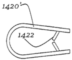
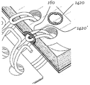
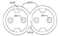
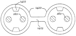
도 33a 내지 도 33f는 트윈-와이어 바인딩 장치의 루프의 팁에 부착을 위한 와셔형 요소의 도면.
도 34a 내지 도 34e는 트윈-와이어 바인딩 장치의 루프의 팁에 부착을 위한 다른 와셔형 요소의 도면.
도 35a 내지 도 35b는 트윈-와이어 바인딩 장치의 루프의 팁에 부착을 위한 적소 배치 요소의 도면 및 단면도.
도 36a 내지 도 36e는 바인딩된 구성 요소를 적소에 고정하기 위한 트윈-와이어 바인딩 장치의 루프 상의 팁의 도면.
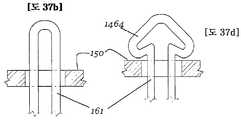
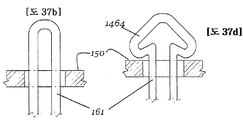
도 37a는 바인딩된 구성 요소를 적소에 고정하기 위한 트윈-와이어 바인딩 장치의 루프 상의 팁의 도면.
도 37b는 트윈-와이어 바인딩 장치의 루프 상의 팁의 측면도.
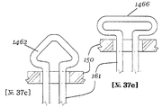
도 37c 내지 도 37e는 바인딩된 구성 요소를 적소에 고정하기 위해 다양한 형상으로 형성된 도 37b의 팁의 측면도.1 is a front perspective view of an unfolded notebook using a twin-wire binding device;
Figure 2 is a detailed top view of the twin-wire binding device of Figure 1;
Figure 3a is a view of one end of a coil-lock of a twin-wire binding mechanism prior to closure / lock according to an embodiment of the present invention.
Figure 3b is a first closed configuration showing one end of a coil-lock twin-wire device in accordance with an embodiment of the present invention;
Figure 3c is a second closed configuration showing one end of a coil-lock twin-wire device according to an embodiment of the present invention;
Figure 3d illustrates a third closed configuration showing one end of a coil-lock twin-wire device according to an embodiment of the present invention;
4 is a diagram of a coil-lock embodiment for a post-closure twin-wire binding system in accordance with an embodiment of the present invention.
5A is a view of one end of a closed-lock pre-lock coil-lock twin-wire device in accordance with an embodiment of the present invention.
Figure 5b is a first closed configuration showing one end of a coil-lock twin-wire device in accordance with an embodiment of the present invention;
Figure 5c is a second closed configuration showing one end of a coil-lock twin-wire device according to an embodiment of the present invention;
Figure 6 is a diagram of a coil-lock embodiment for a post-closure twin-wire binding system in accordance with an embodiment of the present invention.
7 is a perspective view of a coil spine joint;
Figure 8 is an end view of the coil spine joint of Figure 7;
Figures 9a and 9b illustrate various coil spine joint locking devices for a twin-wire binding system attached to a twin-wire device and further illustrate paper and cover materials bound together according to an embodiment of the present invention.
10 is a view of a coil spine joint locking device for a twin-wire binding system showing a coil spine joint attached to a twin-wire device and covering the end of a twin-wire device according to an embodiment of the present invention.
11 is a perspective view of a snap-in lock device for a twin-wire binding system according to an embodiment of the present invention, shown in connection with a notebook.
12 is a plan view of a plurality of snap-in comb lock configurations;
Figure 13 illustrates a snap-in comb lock locked in a binding mechanism and paper and cover materials bound together according to an embodiment of the present invention.
Figure 14 is a perspective view of a segmented opposed closure embodiment for a twin-wire binding system in accordance with an embodiment of the present invention.
15 is a perspective view of three successive segmented opposed closed twin-wire arrangements.
16 is a view of a solder lock embodiment for a twin-wire binding system in accordance with an embodiment of the present invention.
17 shows two views of a solder lock covering a section of a twin-wire device.
18 is a detailed view of an end of a spiral wire binding system;
19 is a view of a solder lock covering a section of the spiral wire device of Fig. 18;
Figure 20 is a flow chart illustrating various methods that may be used to lock the twin-wire binding device;
Figure 21 is a flow chart illustrating an additional method that may be used to lock the twin-wire binding device.
22A-22D illustrate a "staple" shaped device (along the binding axis) for locking together a continuous loop of a twin-wire binding device.
Figures 23a-23c illustrate another "staple" type device (along the binding axis) for locking together a continuous loop of a twin-wire binding device.
24A-24D are diagrams of a "staple" shaped device (also across an axial gap) for locking together adjacent loops of a twin-wire binding device.
25A-25D are diagrams of a "staple" -type device (across an axial gap) for locking together adjacent loops of a twin-wire binding device.
26A-26D are cross-sectional views illustrating steps for attaching a locking element to two wires of a twin-wire binding device.
27A-27D illustrate a "crimp" type device for locking loops of a twin-wire binding device together (across the axial clearance and along the axial clearance).
28A-28D illustrate a "crimp" type device for locking together loops of a twin-wire binding device (across the axial clearance and along the axial clearance).
29A-29F are cross-sectional views illustrating a " guardrail "type device (along the binding axis) for locking loops of a twin-wire binding device together.
30 is a view of a "guardrail" -like element (along the binding axis) for locking together loops of the twin-wire binding device;
31A-31F are views and cross-sectional views of elements for attachment to a tip of a loop of a twin-wire binding device.
32A-32B illustrate another element for attachment to a tip of a loop of a twin-wire binding device.
33A-33F are views of a washer-like element for attachment to a tip of a loop of a twin-wire binding device.
34A-34E are diagrams of different washer-like elements for attachment to a tip of a loop of a twin-wire binding device.
35A-35B are views and cross-sectional views of a locating element for attachment to a tip of a loop of a twin-wire binding device.
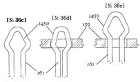
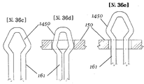
36A-36E illustrate a tip on a loop of a twin-wire binding device for securing a bound component in place.
37A is a diagram of a tip on a loop of a twin-wire binding device for securing a bound component in place;
37B is a side view of the tip on the loop of the twin-wire binding device;
Figures 37c-e are side views of the tip of Figure 37b formed in various shapes to secure the bound components in place.
도 1은 트윈-와이어 바인딩 시스템, 디바이스, 기구 또는 장치(110)를 이용하는 공책(100)의 사시도이다. 트윈-와이어 바인딩 장치(110)는 종이(150), 앞표지(120), 뒷표지(130), 폴더, 분배기, 포켓 분배기, 워크시트, 저장 파우치, 기능 디바이스, 워크북 페이지 또는 다른 내용물(content) 페이지, 이들의 조합 또는 다른 내용물을 포함하는, 임의의 광범위한 바인딩된 구성 요소를 함께 바인딩되거나 결합하는데 사용될 수 있다. 앞표지(120) 및 뒷표지(130)는 각각의 종이(150)의 시트보다 각각 더 두껍고 그리고/또는 더 단단하여 공책(100)에 보호 및 강성을 제공한다. 각각의 종이(150)의 시트 및 각각의 앞표지(120) 및 뒷표지(130)는 그 외부 에지 부근에 구멍(140)의 열을 포함한다. 구멍(140)은 트윈-와이어 바인딩 장치(110)의 권선 또는 코일을 그 내부에 수용하여 종이(150)의 개별 페이지 및/또는 표지(120, 130)가 바인딩되게 하고 그리고/또는 책에서와 같이 넘겨지게 하도록 치수 설정되고 이격된다. 트윈-와이어 장치(110)는 중앙 길이방향 또는 길이방향 축(115)을 포함하거나 이들을 따라 연장할 수 있고, 상부 단부(116)로부터 저부 단부(117)로 연장할 수 있다.FIG. 1 is a perspective view of a
도 2는 트윈-와이어 장치(110)의 섹션의 더 상세한 도면을 제공한다. 트윈-와이어 장치라 명명되지만, 장치(110)는 각각의 루프가 2개의 평행하지만 이격된 와이어로 구성되어 있는 장치로서 나타나도록 구성된 연속적인 단일 와이어로 구성될 수 있다. 소위 "트윈-와이어" 바인딩은 2개의 와이어가 대부분의 또는 모든 바인딩 구멍(140)을 통해 연장하도록 단일 와이어 형상으로 구성되거나 또는 다른 방식으로 형성될 수 있다. 단일 연속적인 와이어는 길이방향 축(115)에 대해 일반적으로 원형 방식으로 굴곡되어 복수의 루프를 형성할 수 있다. 바인딩 장치(110)는 플라스틱 또는 금속 와이어(또는 다른 금속)와 같은 단일편의 재료로부터 구성될 수 있고, 약 0.2 mm 내지 약 2 mm의 두께(즉, 직경)를 가질 수 있다.FIG. 2 provides a more detailed view of the section of the twin-
트윈-와이어 구성은 와이어를 대향하는 교번적인 일반적으로 u-형 팁 섹션(160) 및 연결 섹션(170)으로 굴곡함으로써 형성될 수 있다. 각각의 연결 섹션(170)은 축(115)에 일반적으로 평행하게 연장하고, w1의 폭을 갖고, 반면 각각의 팁 섹션(160)은 w2의 폭을 갖는다. 폭 w2는 폭 w1보다 작을 수 있고, 각각의 팁 섹션(160)이 바인딩 구멍(140)을 통해 연장할 수 있도록 구성될 수 있다.The twin-wire configuration can be formed by bending the wires into an alternating, generally
각각의 연결 섹션(170)은 측면도에서 실질적으로 c-형상이고, 도 2의 도면을 참조하여 축(115) 위에서 축(115)에 대해 약 180°만곡될 수 있다[도 4를 참조하여 축(115)의 우측으로]. 팁(160) 섹션은 또한 측면도에서 실질적으로 c-형상일 수 있고, 도 2를 참조하여 축(115) 아래로 길이방향 축(115)에 대해 약 180°만곡될 수 있다[도 4를 참조하여 축(115)의 좌측으로]. 상기 특징에 기초하여, 각각의 팁 섹션(160)의 종료부는 각각의 연결 섹션(170)의 시작부일 수 있다. 유사하게, 각각의 연결 섹션(170)의 종료부는 대략적으로 각각의 팁 섹션(160)의 시작부에 위치될 수 있다.Each connecting
도 4에 도시된 바와 같이, 바인딩 장치(110)는 그 상부 축방향 단부(116) 및/또는 저부 축방향 단부(117)에서 단부 코일을 가질 수 있고, 단부 코일은 팁 섹션(159) 및 연결 섹션(169)을 갖는다. 최말단측 팁 섹션(159)을 구성하는 와이어는 종료점(159')으로 연장하는 것으로 고려될 수 있고, 동 지점에서 와이어는 인접한 연결 섹션(169)을 시작한다. 연결 섹션(169)은 종료점(169')으로 연장하는 것으로 고려될 수 있고, 동 지점에서 와이어는 다음 팁 섹션(160)을 시작한다. 팁 섹션(160)은 종료점(160')으로 연장하는 것으로 고려될 수 있고, 동 지점에서 와이어는 인접한 연결 섹션(170)을 시작한다. 연결 섹션(170)은 종료점(170')으로 연장하는 것으로 고려될 수 있고, 동 지점에서 와이어는 다음의 팁 섹션을 시작하는 등이다. 바인딩 장치(110) 주위에 대략 절반 정도이거나 팁 섹션과 연결 섹션 사이의 "개방" 간극에 대해 대향하거나 약 180도인 여기에 설명된 종료점들은 단지 예일 뿐이고, 한정으로 의도된 것은 아니다. 설명된 방식으로 와이어를 굴곡함으로써, 장치의 전체 외관은 트윈-와이어 장치(110)의 것이지만, 단일 와이어로 성취된다.4, the
팁 섹션(160)과 연결 섹션(170)은 또한 다른 방식으로 규정되거나 고려될 수도 있다. 예를 들어, 일 경우에 각각의 팁 섹션(160)은 축(115)에 대해 거의 360도로, 일반적으로 원형/원주방향 방식으로 연장되는 2개의 평행한 와이어 섹션을 포함하는 바인딩 장치(110)의 섹션으로 고려될 수 있다. 이 구성에서, 각각의 팁 섹션(160)은 또한 동축으로 배열된 코일, 코일 섹션 또는 바인딩 코일이라 명명될 수 있다. 각각의 팁 섹션(160)은 2개의 평행한 와이어가 만나는 팁에서 종료할 수 있다.
이 구성 하에서, 각각의 코일 섹션(160)은 그 사이에 위치된 연결 또는 접속 섹션(170)에 의해 인접한 코일 섹션에 연결될 수 있다. 이 경우에, 각각의 연결 섹션(170)은 단지 와이어 장치의 직선형 축방향 연장부, 예를 들어 도 2의 치수 w1에 의해 지시된 섹션만을 구성할 수 있고, 트윈-와이어 장치(110)의 모든 원주방향 연장부는 코일 섹션(160)으로 고려된다.Under this configuration, each
본 명세서에 설명된 트윈-와이어 바인딩 시스템은 예를 들어 상부 단부(116) 및 저부 단부(117)에, 트윈-와이어 장치(110)의 시작부 및 종료부가 반드시 존재하는 유한 길이를 갖는다. 이들 단부에서, 트윈-와이어 장치(110)가 전통적으로 규정된 종료부 또는 잠금 기구를 갖지 않는다. 게다가, 이러한 폐쇄 또는 잠금 기구 없이, 종이(150), 표지(120/130) 및/또는 다른 바인딩된 구성 요소와 같은 바인딩된 구성 요소는 전통적인 트윈-와이어 장치(110)의 전체 길이를 따른 개방 간극에 기인하여 바인딩 장치(110)로부터 완전히 또는 부분적으로 분리될 수 있다.The twin-wire binding system described herein has, for example, a finite length at the
이하에 설명된 다수의 실시예는 도 1, 도 2 및 도 4에 도시된 것과 같은 트윈-와이어 바인딩 장치를 위한 잠금 또는 폐쇄 기구로서 기능하는 다양한 실시예를 설명한다. 이하에 설명된 각각의 잠금 기구는 바인딩 장치에 의해 바인딩되는 종이, 표지 및/또는 다른 내용물이 바인딩 장치를 완전히 탈출할 수 없는 것을 보장하는 것이 가능할 수 있다. 각각의 실시예는 서로 차이가 있을 수 있지만, 도면의 도면 부호는 전체로서 트윈-와이어 장치(110), 팁 섹션(160), 연결 섹션(170), 앞표지(120), 뒷표지(130), 구멍(140) 및 종이(150)와 같은 일관된 요소에 대해 일관적으로 유지된다.A number of embodiments described below describe various embodiments that function as a locking or closing mechanism for a twin-wire binding device such as that shown in Figs. 1, 2, and 4. Fig. Each of the locking mechanisms described below may be possible to ensure that the paper, labels and / or other contents bound by the binding device can not completely escape the binding device. Although the respective embodiments may be different from each other, reference numerals in the drawings denote a twin-
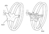
코일-로크라 명명될 수 있는 제 1 실시예가 도 3a 내지 도 3d 및 도 4에 도시되어 있고, 적어도 하나의 바인딩 코일이 그 자신에 또는 연결부에 원주방향으로 부착되어 있는 실시예이다. 도 3a는 트윈-와이어 장치(110)의 섹션이 규정된 단부(175)를 갖는 본 실시예에 따른 폐쇄 전의 코일-로크 트윈-와이어 장치의 일 단부의 도면이다. 트윈-와이어 장치(110)는 절단/종료되어 있고, 최인접 대형 팁 섹션(160) 주위에 잠금되기 전에 그 단부(175)가 외향으로 굴곡된 상태로 도시되어 있다. 절단은 최종 대향 팁 섹션(160)이 형성된 후에 그리고 다음 연결 섹션(170)의 완료 전에 행해져서 충분히 자유로운 와이어가 대향 팁 섹션(160)을 통해 스레딩되고, 굴곡되어 자체로 클램프되게 할 수 있다. 대향 팁 섹션(160)은 최인접 대향 팁 섹션(160)일 수 있는데, 이는 요구되는 와이어 재료의 양을 감소시킬 수 있다는 것이 이해되어야 한다. 그러나, 단부(175)는 그 단부에서 팁 섹션(160) 이외의 다른 팁 섹션(160)에 대해 굴곡될 수 있다. 제조 선호도는 이 팁 섹션(160)이 이 잠금 섹션을 생성하도록 요구된 와이어 재료의 길이 및 와이어 단부(175)를 수용할 것이라는 것을 지시할 것이다. A first embodiment, which can be named coil-lock, is shown in Figs. 3a to 3d and 4, in which at least one binding coil is attached to itself or to the connection in the circumferential direction. 3A is a view of one end of a pre-closed coil-lock twin-wire device according to this embodiment having a
도 3b는 코일-로크 트윈-와이어 장치의 일 단부를 도시하는 제 1 폐쇄 구성을 도시한다. 도 3b에서, 단부 또는 연장부(180)는 최인접 대향 팁 섹션(160) 위로 연장되고, 루프 내로 반경방향 내향으로 편향되고 자신 위로 또는 자신을 향해 재차 클램프되어, 이에 의해 트윈-와이어 장치(110)의 나머지와 단부(180)를 폐쇄하거나 잠금한다. 단부(180) 또는 다른 인접한 부분은 트윈 와이어 장치와 접촉하게 될 수 있고, 또는 와이어의 두께보다 작은 간극을 형성하도록 충분히 폐쇄될 수 있고, 또는 더 큰 간극을 형성할 수도 있다.Figure 3b shows a first closed configuration showing one end of a coil-lock twin-wire arrangement. In Figure 3b, the end or
도 3c는 단부(185)가 최인접 대향 팁 섹션(160)을 통해 스레딩되고, 반경방향 외향으로 굴곡되고 자신 상에 또는 자신을 향해 재차 굴곡되어, 이에 의해 트윈-와이어 장치(110)의 나머지와 단부(185)를 폐쇄하거나 잠금하는 제 2 폐쇄 구성을 도시한다. 도 3a는 단부(175/185)를 스레딩 및 굴곡하기 전에 도 3c의 실시예를 도시할 수 있다. 도 4는 도 3c와 본질적으로 동일한 구성을 도시하지만, 앞표지(120), 뒷표지(130) 및 종이(150)의 시트와 관련하여 트윈-와이어 장치(110)를 도시한다. 도 3d는 단부(190)가 최인접 대향 팁 섹션(160)을 통해 스레딩되고, 측방향으로 굴곡되고 자신 상에 또는 자신을 향해 재차 클램프되어 이에 의해 트윈-와이어 장치(110)의 나머지와 단부(190)를 폐쇄하거나 잠금하는 제 3 폐쇄 구성을 도시한다. 이 구성에서 그리고 전술된 모든 다른 잠금 구성에서, 마지막 또는 축방향 단부 구멍(140)은 2-와이어 구성으로 와이어 장치의 권선을 수용한다.3C shows that the
도 5a 내지 도 5c 및 도 6은 코일-로크의 제 2 실시예를 도시한다. 도 5a는 본 특정 실시예에 따른 폐쇄 전의 코일-로크 트윈-와이어 장치(110)의 일 단부를 도시한다. 트윈-와이어 장치(110)의 섹션은 최인접 대향 연결 섹션(170) 주위에 루프/잠금되기 전에 그 단부(210)가 일반적으로 반경방향 내향으로 굴곡된 상태로 도시되어 있다. 바인딩 장치(110)의 와이어는 마지막 대향 팁 섹션(160)이 완전히 형성된 후에 단부(210)에서 절단될 수 있어 충분히 자유로운 와이어가 인접 대향 연결 섹션, 예를 들어 최인접 대향 연결 섹션(170)을 통해 스레딩되게 하고, 이어서 굴곡되어 자체로 재차 클램프되게 한다. 이전의 실시예에서 설명된 바와 같이, 단부(210)에 인접한 자유로운 와이어의 길이는 자유로운 와이어가 잠금 섹션을 생성하도록 굴곡되는 대향 연결 섹션의 위치일 수도 있는 바와 같이 제조 선호도에 기초하여 조정될 수 있다. 대향 연결 섹션은 바로 인접한 연결 섹션, 또는 바로 인접한 연결 섹션 이후의 다음의 연결 섹션, 또는 더 이격된 연결 섹션일 수도 있다.Figures 5A-5C and 6 show a second embodiment of a coil-lock. 5A shows one end of a coil-lock twin-
도 5b는 최인접 대향 연결 섹션(170) 아래로 통과되고, 반경방향 외향으로 굴곡되고 자신 상에 또는 자신을 향해 재차 클램프되어 이에 의해 트윈-와이어 장치(110)의 나머지와 단부(220)를 폐쇄하거나 잠금하는 단부(220)를 도시한다. 도 5c는 최인접 대향 연결 섹션(170) 위로 통과되고, 반경방향 내향으로(또는 측방향으로) 굴곡되고 자신 상에 또는 자신을 향해 재차 클램프되어 이에 의해 트윈-와이어 장치(110)의 나머지와 단부(230)를 폐쇄하거나 잠금하는 단부(230)를 도시한다. 도 6은 도 5c와 본질적으로 동일한 구성을 도시하지만, 앞표지(120), 뒷표지(130) 및 종이(150)의 시트와 관련하여 트윈-와이어 장치(110)를 도시한다. 이 구성에서 그리고 도 5a 내지 도 5c 및 도 6의 모든 다른 상기 잠금 구성에서, 마지막 또는 축방향 단부 구멍(140)은 단일-와이어 구성으로 와이어 장치의 권선을 수용한다.5b is passed below the nearest
도 7 내지 도 10은 잠금 디바이스가 바인딩 장치의 부분을 일반적으로 원주방향으로 그리고/또는 축방향으로 결합하는데 이용되는 본 명세서에서 스파인 조인트라 명명되는 다른 실시예를 도시한다. 도 7은 잠금 디바이스/코일 스파인 조인트의 일 실시예의 사시도이다. 코일 스파인 조인트(310)는 일반적으로 스파인 섹션(325)과, 그 축방향 단부에서 및 그 동일한 측면에서 스파인 섹션(325)에 결합된 한 쌍의 연결 후크 섹션들(320, 330)을 포함할 수 있다. 코일 스파인 조인트(310)는 연결 후크 섹션(320, 330)에 비교하여 대향 측면에서 스파인 섹션(325)에 결합된 팁 후크 섹션(340)을 또한 포함할 수 있다. 팁 후크 섹션(340)은 연결 후크 섹션(320, 330)에 대향하고 이들 사이에 배치된다. 코일 스파인 조인트(310)는 바인딩 장치(110)의 인접 연결 섹션(170)과 대향 팁 섹션(160)을 결합하도록 구성되고 적용된다. 코일 스파인 조인트(310)는 사출 성형 플라스틱/폴리머, 블로우 성형 플라스틱/폴리머 또는 임의의 다른 성형 플라스틱 또는 폴리머를 포함하는 다양한 재료로부터 제조되거나 형성될 수 있다. 대안적으로, 코일 스파인 조인트(310)는 스탬핑된 또는 다이 절단된 시트 금속 또는 시트 플라스틱/폴리머, 주조 또는 다이캐스트 금속 또는 플라스틱/폴리머, 수지, 수지계 재료 또는 복합 재료 등으로부터 제조되거나 형성될 수 있다. 당 기술 분야의 숙련자들은 본 명세서의 개시 내용의 사상 또는 범주로부터 벗어나지 않고, 코일 스파인 조인트(310)가 형성될 수 있는 다른 재료 또는 재료를 형성하는 다른 방법을 즉시 인식할 수 있다.Figs. 7-10 illustrate another embodiment, referred to herein as a spine joint, in which a locking device is used to couple a portion of a binding device generally circumferentially and / or axially. 7 is a perspective view of one embodiment of a locking device / coil spine joint. The coiled spine joint 310 can generally include a
도 8은 도 7의 코일 스파인 조인트(310)의 단부도이다. 이 도면에서, 연결 후크 섹션(320)은 연결 섹션 와이어(170)의 단면도와 협동적으로 결합하여(예를 들어, 권취하여) 도시되어 있다. 유사하게, 팁 후크 섹션(340)은 팁 섹션 와이어(160)의 단면도와 협동적으로 결합하여(예를 들어, 권취하여) 도시되어 있다. 각각의 후크 섹션(320, 330, 340)은 가능하게는 스파인 섹션(325)과 조합하여, 연관된 섹션(160, 170) 주위에서 적어도 약 180도로 연장될 수 있다.8 is an end view of the
도 9a는 종이(150) 및 표지(120, 130)와 관련하여 트윈-와이어 장치(110)에 부착된 도 7 및 도 8의 잠금 디바이스(300)의 도면이다. 적어도 하나의 코일 스파인 조인트(310)는 연결 후크 섹션(320, 330)이 트윈-와이어 장치(110)의 인접 연결 섹션(170) 상에 기계적으로 후크 결합되고 반면 팁 후크 섹션(340)은 트윈-와이어 장치(110)의 대향 팁 섹션(160) 상에 기계적으로 후크 결합되도록 트윈-와이어 장치(110)에 대해 협동적으로 끼워진다. 그러나, 원한다면, 이 구성은 후크 섹션(320, 330)이 팁 섹션(160)에 연결되고 후크 섹션(340)이 연결 섹션(170)에 연결되도록 반전될 수 있지만, 코일 스파인 조인트(310)의 간격 및 구성은 이에 따라 조정될 필요가 있을 수도 있다. 부가의 코일 스파인 조인트(310)가 동일한 방식으로 트윈-와이어 장치(110) 상에 유사하게 후크 결합될 수 있어, 종이(150) 및/또는 표지(120, 130) 또는 다른 내용물이 트윈-와이어 바인딩 장치(110)로부터 느슨하게 되는 것을 방지하기 위해, 트윈-와이어 장치(110)를 협동하여 폐쇄하고, 걸치고 그리고/또는 잠금하는 일련의 코일 스파인 조인트(310)가 존재하게 된다.9A is a view of the
도 9b는 코일 스파인 조인트(311)가 다수의 세트의 연결 섹션(170)과 팁 섹션(160)을 따라 축방향으로 연장하고 여분의 후크 섹션을 갖는 것을 제외하고는, 도 9a의 것과 유사한 코일 스파인 조인트 잠금 실시예(301)를 도시한다. 코일 스파인 조인트(311)는 각각의 세트를 함께 후크 결합하거나 세트의 단지 일부만을 함께 후크 결합하는 2개 이상의 세트의 연결 섹션(170)과 팁 섹션(160) 위로 연장할 수 있다. 적어도 하나의 코일 스파인 조인트(311)는 연결 후크 섹션(320, 330)이 트윈-와이어 장치(110)의 인접 연결 섹션(170) 상에 기계적으로 후크 결합되고 반면 팁 후크 섹션(340)은 트윈-와이어 장치(110)의 대향 팁 섹션(160) 상에 기계적으로 후크 결합되도록 트윈-와이어 장치(110)에 대해 협동적으로 끼워진다. 부가의 코일 스파인 조인트(311)가 종이(150) 및/또는 표지(120, 130) 또는 다른 내용물이 트윈-와이어 바인딩 장치(310)로부터 분리되게 되는 것을 방지하기 위해, 트윈-와이어 장치(11)를 폐쇄하고 잠금하도록 동작하는 일련의 코일 스파인 조인트가 존재할 때까지 동일한 방식으로 트윈-와이어 장치(11) 상에 유사하게 후크 결합될 수 있다.Figure 9b shows a coil spine similar to that of Figure 9a except that the coil spine joint 311 extends axially along the multiple sets of connecting
도 10은 바인딩 장치(110)의 단부 섹션(350)에 결합되고, 인접하여 위치되거나 커버하는 코일 스파인 조인트 잠금 실시예(300)를 도시한다. 도 10의 스파인 조인트의 구조 및 기능성은, 도 10의 스파인 조인트가 트윈-와이어 장치(110)의 단부 섹션(350)을 커버하는 것을 제외하고는 도 9a 및 도 9b의 것과 유사하다. 단부 섹션(350)은 트윈-와이어 장치(110)가 종료하기 위해 몇몇 점에서 절단되어야 하기 때문에 완전한 연결 섹션이 아니라 오히려 절단되어 있는 연결 섹션이다. 도 9a 및 도 9b는 코일(110)의 단부 이외의 다수의 위치에서 코일 스파인 조인트를 도시하고, 도 10은 코일(110)의 단부 상의 코일 스파인 조인트를 도시한다. 이들은 단지 예일 뿐이고, 위치들의 다른 조합이 코일 스파인 조인트를 위해 사용될 수 있다.FIG. 10 illustrates a coiled-in
하나 이상의 코일 스파인 조인트(310)가 폐루프 또는 잠금된 구성을 생성하기 위해 트윈-와이어 장치(110)의 길이를 따른 패턴으로 배열될 수 있고, 코일 스파인 조인트(310)는 트윈-와이어 장치(110)의 단부 섹션 상에 사용될 수도 있고 또는 사용되지 않을 수도 있다. 예를 들어, 2개 이상의 코일 스파인 조인트(310)는 트윈-와이어 장치(110) 상에 후크 결합될 수 있고, 적어도 하나의 코일 스파인 조인트(310)가 트윈-와이어 장치(110)의 일 단부(116) 부근에 또는 인접하여 위치될 수 있고, 적어도 하나의 코일 스파인 조인트(310)는 트윈-와이어 장치(110)의 다른 단부9117) 부근에 또는 인접하여 위치될 수 있다.One or more coil spine joints 310 may be arranged in a pattern along the length of the twin-
도 11 내지 도 13은 바인딩 장치의 부분을 축방향으로 결합하는 본 명세서의 스냅-인 코움 코일-로크라 명명된 다른 잠금 디바이스를 도시한다. 도 11은 앞표지(120), 뒷표지(130) 및 종이(150)를 바인딩하는 전통적인 트윈-와이어 장치(110)를 갖고 도시된 스냅-인 코움 로크 실시예(400)의 사시도이다. 도 11은 또한 트윈-와이어 장치(110) 내에 삽입을 위해 위치된 분해된 스냅-인 코움 로크 구성 요소(410)를 도시한다.11-13 illustrate another locking device, referred to herein as a snap-in comb coil-lock, which axially couples a portion of the binding device. 11 is a perspective view of the illustrated snap-in
도 12는 스냅-인 코움 로크 구성 요소(410)의 다양한 실시예의 평면도를 도시한다. 스냅-인 코움 로크 구성 요소(410)는 일반적으로 그 길이를 따라 이격된 1개, 2개 또는 그 이상의 핑거 요소(430)를 갖는 스파인 요소(420)를 포함할 수 있다. 스파인 요소(420)는 일반적으로 편평하고 평면형일 수 있고, 각각의 핑거 요소(430)는 일반적으로 편평하고 스파인 요소(420)와 동일 평면에 있을 수 있다. 각각의 핑거 요소(430)는 스파인 요소(420)로부터 실질적으로 90°, 또는 소정의 다른 각도로 돌출하고, 연속적인 핑거 요소(430)가 연관된 팁 섹션(160) 사이의 거리와 대략 동일한 거리로 이격되도록 구성되는 걸림 기구를 구비하거나 포함할 수 있다. 이 구성에서, 각각의 핑거 요소(430)는 팁 섹션(160) 내에 끼워지고 협동적으로 결합하도록 적용된다. 도 11 내지 도 13에 도시된 복수의 핑거 요소(430)를 위한 걸림 기구는 일반적으로 팁 섹션(160)의 인접 와이어 내에 끼워져서 이격하여 확산하도록 적용된 한 쌍의 각형성된 선단 에지를 갖는 일반적으로 화살표 형상일 수 있다.12 illustrates a top view of various embodiments of a snap-in
각각의 핑거 요소(430)는 핑거 요소(430)가 팁 섹션(160)을 통해 완전히 삽입된 후에, 후단 표면이 핑거 요소(430)가 바인딩 장치(110)로부터 당겨지는 것을 방지하기 위한 걸림 기구로서 작용하도록 팁 섹션(160)의 각각의 와이어에 결합하도록 구성된 한 쌍의 후단/보유 표면을 또한 포함할 수 있다. 대안적으로, 각각의 핑거 요소(430)는 각각의 핑거 요소(430)가 삽입되고, 이어서 전체 코움(410)이 예를 들어 축방향으로 이동되어 코움(410)을 적소에 잠금하도록 소정 각도로 삽입되거나 또는 2개(또는 그 이상)의 단계 작동으로 삽입되도록 형성될 수 있다.Each
스파인 요소(420)의 길이는 도 12에 도시된 것으로부터 변경될 수 있어 스파인 요소(420)/구성 요소(410)가 바인딩 장치(110)와 일반적으로 동일하거나 작은 길이를 갖게 된다. 또한, 특정 핑거 요소(430)는 구성 요소(410)가 각각의 팁 섹션(160)에 결합하지 않도록 생략될 수도 있지만, 이 경우에 존재하는 핑거편(430)은 대응 팁 섹션(160)의 일부에 결합하도록 이격되어야 한다. 예를 들어, 구성 요소(410)는 팁 섹션(160) 중 1개, 2개 또는 그 이상에 결합할 수도 있다.The length of the
도 13은 바인딩 장치(110)에 의해 함께 바인딩된 종이(150) 및 표지(120, 130)와 관련하여 스냅-인 코움 로크(410)를 도시한다. 이 도면에서, 스냅-인 코움 로크 구성 요소(410)는 팁 섹션(160)을 경유하여 트윈-와이어 장치(110)와 결합되어 도시되어 있다. 핑거 요소(430)의 팁은 팁 섹션(160)의 루프와 정렬될 수 있다. 사용자 또는 삽입 디바이스는 이어서 팁 섹션(160)의 루프를 통해 핑거 요소(430)를 압박하도록 반경방향 내향력을 인가할 수 있다. 각각의 팁(430)은 팁 섹션(160)의 한 쌍의 와이어 사이의 폭보다 큰 폭을 가질 수 있어 각각의 핑거 요소(430)가 그를 통해 삽입됨에 따라 팁 섹션(160)의 트윈 와이어가 선단 표면에 의해 확산 이격될 수 있게 된다. 트윈 와이어는 연관된 핑거 요소(430)가 완전히 삽입된 후에 함께 수렴/스냅 결합될 수 있다.13 illustrates snap-in
핑거 요소(430)의 각형성된/화살표 형상에 기초하여, 전체 스냅-인 코움 구성 요소(410)는 트윈-와이어 장치(110)와 잠금 가능하게 결합되어 유지될 수 있어, 이에 의해 종이(150) 및/또는 표지(120, 130) 또는 다른 내용물이 트윈-와이어 장치(110)로부터 탈출하는 것을 방지한다. 핑거 요소(430)는 핑거 요소를 제거하는데 요구되는 것보다 낮은 힘이 핑거 요소(430)를 삽입하는데 요구되도록 각각의 핑거 요소(430)가 구성될 수 있도록 성형될 수 있다.Based on each formed / arrowed shape of the
바인딩 장치(110)와 관련하여 핑거 요소(430)의 특정 도시된 위치는 예로서 제공된 것이라는 것이 주목되어야 한다. 핑거 요소(420)는 요구된 바인딩 장치(110)의 원주 주위의 다른 위치에 위치될 수 있다. 도 13에 도시된 점으로부터 바인딩 장치(110)의 원주 주위로 대략 180도 지점에서 핑거 요소(430)를 삽입하는 것이 더 용이할 수 있다.It should be noted that the particular illustrated location of the
본 실시예는 일반적으로 화살표 형상을 갖는 것으로서 핑거 요소(430)를 도시하고 있다. 그러나, 화살표 형상이 아닌 형상이 이용될 수 있고 조립의 용이성과 결합의 효용 사이의 균형을 제공한다. 다른 핑거 요소(430) 형상이 본 명세서의 개시 내용의 사상 또는 범주로부터 벗어나지 않고 본 실시예에서 걸림 기구로서 사용을 위해 적용될 수 있다.This embodiment shows the
도 14 및 도 15는 본 명세서에서 교번 코일-로크라 명명되는 다른 바인딩 장치 시스템을 도시한다. 도 14는 세그먼트형 대향 폐쇄 실시예(500)의 사시도이다. 본 실시예는 각각의 세그먼트(510)가 축(115)을 따른 바인딩된 구성 요소(120, 130, 150)의 길이보다 짧을 수 있는 전통적인 트윈-와이어 장치의 세그먼트(510)를 이용한다. 더욱이, 각각의 세그먼트(510)는 일 세그먼트(510)의 팁 섹션(160)이 인접 세그먼트(510)의 팁 섹션(160)으로부터 실질적으로 180°반전된 방향으로 지향하도록[또는 팁(160)이 축방향 간극의 대향 측면들 상에 위치되고, 또는 세그먼트(150)의 축방향 연장 간극이 오정렬되거나 180°만큼 오정렬됨] 그 인접 세그먼트(510)로부터 원주방향으로 오정렬되고 그리고/또는 반전 배향될 수 있다.Figures 14 and 15 illustrate another binding device system, herein termed alternate coil-lock. 14 is a perspective view of a segmented
따라서, 하나 이상의 세그먼트(510a)는 일 방향으로 지향하는 이들의 팁 섹션(160)을 각각 가질 수 있고[또는 팁(160)은 축방향 간극의 우측에 위치되고, 또는 이들의 간극은 그 상부 단부에 있음], 반면 인접한 반전된 하나 이상의 세그먼트(510b)는 반대 방향에서 180°인 방향으로 지향하는 이들의 팁 섹션(160)을 갖는다(또는 팁들은 축방향 간극의 좌측에 위치되고, 또는 이들의 간극은 그 저부 단부에 있음). 연속적인/인접 세그먼트(510a, 510b)의 배향을 반전시킴으로써, 전통적인 트윈-와이어 장치 내에 존재할 수 있는 임의의 간극은 각각의 인접 세그먼트 내에서 오프셋되어 종이(150) 및/또는 표지(120, 130) 또는 다른 내용물이 바인딩 시스템으로부터 느슨해질 수 있는 기회를 감소시킨다.Thus, the one or
도 15는 3개의 연속적인 세그먼트형 대향 폐쇄 트윈-와이어 세그먼트(510a, 510b)의 사시도이다. 2개의 단부 세그먼트(510a)가 단부 세그먼트(510a)가 표지(120, 130) 및 종이(150)에 대해 폐쇄될 때 존재할 수 있는 것보다 더 큰 팁 섹션(160)과 연결 섹션(170) 사이의 간극을 갖고 도시되어 있지만, 이 구성에서 폐쇄 전에 로딩 위치를 도시하기 위해 예시적인 목적으로 도시되어 있다. 중간 세그먼트(510b)는 함께 훨씬 더 근접한 팁 섹션(160)과 연결 섹션(170) 사이의 간극을 갖고 도시되어 있는데, 이는 일반적으로 표지(120, 130) 및 종이(150) 및/또는 다른 내용물이 설치되고 코일 세그먼트(510b)가 폐쇄된 후의 외관이다.15 is a perspective view of three successive segmented opposed closed twin-
본 실시예를 위한 원하는 결과는 최소 2개의 반전 배향된 세그먼트에 의해 성취될 수 있다. 도 14는 5개의 세그먼트를 도시한다. 당 기술 분야의 숙련자는 임의의 수의 교번적인 반전 배향된 세그먼트(510a, 510b)가 본 실시예를 위해 구현될 수 있다는 것을 즉시 이해할 수 있을 것이다.The desired result for this embodiment can be achieved by a minimum of two inversely oriented segments. Figure 14 shows five segments. One of ordinary skill in the art will readily appreciate that any number of alternatingly oriented
도 16 및 도 17은 본 명세서에서 땜납 코일-로크라 명명되는 바인딩 장치의 부분을 일반적으로 원주방향으로 연결하는 잠금 디바이스의 다른 실시예를 도시한다. 도 16은 본 발명의 실시예에 따른 트윈-와이어 바인딩 시스템용 땜납 로크 실시예(600)를 도시한다. 본 실시예(600)에서, 전통적인 트윈-와이어 장치(110)는 팁 섹션(160)이 연결 섹션(170)에 대향하고 구멍(140)을 경유하여 하나 이상의 표지(들)(120/130) 및 종이(150)를 함께 바인딩하는 상태로 도시되어 있다. 본 실시예는 팁 섹션(160)과 대향 연결 섹션(170) 사이의 간극을 가로질러 연결하고 폐쇄하고/원주방향으로 연장하는 땜납 용접부(610)를 이용한다. 땜납 용접부(610)는 팁 섹션(160) 및 대향 인접 연결 섹션(170)을 포함하는 와이어를 부분적으로 둘러싸고 그에 부착한다. 본 실시예에서, 땜납 용접부(610)는 팁 섹션(610)의 외부 에지를 따라 각각의 팁 섹션(160)에 대해 약 180°연장될 수 있다. 땜납 용접부(610)는 각각의 팁 섹션(160)의 최대 폭의 약 2배 이하의 축(115)을 따라 연장하는 총 길이를 가질 수 있어 충분한 접합/결합을 여전히 제공하면서 재료 절약을 제공한다.16 and 17 illustrate another embodiment of a locking device that generally connects a circumferential portion of a portion of a binding device, referred to herein as a solder coil-lock. 16 illustrates a
도 17은 도 16의 실시예와 비교할 때 땜납 용접부가 팁 섹션(160)과 연결 섹션(170) 주위에서 이들에 대해 더 많은 영역을 커버하는 대안적인 땜납 로크의 도면이다. 도 17의 실시예에서, 땜납 용접부(610)는 팁 섹션(160) 및 대향 인접 연결 섹션(170)을 포함하는 와이어를 완전히 둘러싸고 그에 부착되어, 팁 섹션(160)의 말단부의 중심부에 충전한다.17 is a view of an alternative solder lock where the solder welds cover more areas about the
도 16 및 도 17의 결합/폐쇄 디바이스는 지금까지 팁 섹션(160) 및 연결 섹션(170)의 와이어 표면을 습윤하여 고착하고 이어서 고체로 냉각되는 고온 용융 금속을 사용하는 형성을 암시할 수 있는 "땜납 용접부"를 사용하는 것으로서 설명되어 있다. 이 경우에, 땜납 용접부(610)는 웨이브 납땜(wave weldering), 수동 납땜 또는 다른 납땜 방법에 의해 성취될 수 있다. 그러나, 이들에 한정되는 것은 아니지만, 습윤되고 냉각되어 땜납 용접부(610)를 형성할 수 있는 접착제 및/또는 용융/용융 가능/열가소성 플라스틱 또는 폴리머 물질을 포함하는 다른 재료가 사용될 수 있다는 것이 주목되어야 한다. 따라서, 땜납 용접부(610)는 다른 재료들 중에서도, 금속 땜납, 플라스틱 또는 폴리머 땜납 또는 접착제 재료 또는 이들의 조합을 포함하거나 이들로 제조될 수도 있다.The engagement / closure device of Figs. 16 and 17 has been described as a "closure " device that can hint at the wire surface of the
하나 이상의 땜납 용접부(610)가 트윈-와이어 바인딩 기구(110)에 다양한 위치에서 인가될 수도 있다. 일 경우에, 하나의 땜납 용접부(610)가 트윈-와이어 바인딩 기구(110)의 일 단부(116/117)에 근접하여 위치될 수 있고, 다른 땜납 용접부(610)는 트윈-와이어 바인딩 기구(110)의 대향 단부(116/117)에 근접하여 배치될 수 있다. 이 특정 배치는 비교적 적은 재료 및 제조 비용으로, 트윈-와이어 바인딩 기구(110) 내에 표지(120/130), 종이(150) 및/또는 다른 내용물을 유지하기 위해 유리할 수 있다. 그러나, 제조 선호도는 얼마나 많은 땜납 용접부(610)가 트윈-와이어 바인딩 기구(110) 및 그 위치를 따라 사용되는지를 지시할 것이다.One or more solder welds 610 may be applied to the twin-wire
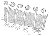
도 18 및 도 19는 본 명세서에 땜납 나선형-로크라 명명된 바인딩 장치를 도시한다. 도 18 및 도 19는 예를 들어 도 1 및 도 2에 도시된 바와 같이 트윈-와이어 바인딩 기구(110)에 대조적으로 종이(150) 내의 구멍(140)을 통해 스레딩되는 연속적인 코일의 나선 내로 형성되는 와이어(710)를 포함하는 나선형 와이어 바인딩 시스템을 도시한다. 나선형 와이어(710)는 와이어(710)의 마지막 코일을 에워싸거나 그 주위에 권취되는 루프(720) 내에서 종료한다. 도 18은 나선형 와이어 바인딩 시스템의 단부들이 영구적으로 고정되지 않는 나선형 와이어 바인딩 시스템을 도시한다.Figs. 18 and 19 illustrate a binding device, referred to herein as a solder spiral-lock. 18 and 19 are formed into the spiral of a continuous coil threaded through
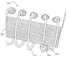
도 19는 나선형 와이어 장치의 섹션을 커버하는 땜납 로크 실시예(700)의 도면이다. 도 19는 루프(720) 둘레에 땜납 용접부(810)의 추가에 의해 도 18에 일치한다. 땜납 용접부(810)는 루프(720)를 코일 와이어(710)에 잠금하고, 커버하고, 고정하여, 루프(720)가 코일 와이어(710)로부터 느슨해지는 것을 방지한다. 땜납 용접부(810)는 나선형 와이어 장치의 일 단부[상부 단부(116) 또는 저부 단부(117), 예를 들어 도 1 참조]에 근접할 수 있다. 제 2 땜납 용접부(810)는 나선형 와이어 장치의 대향 단부[저부 단부(117) 또는 상부 단부(116)]에 근접할 수 있다. 도 19는 "땜납 용접부"를 사용하는 것으로서 설명되어 있지만, 땜납 용접부(810)는 땜납 용접부(610)에 대해 상기에 개략 설명된 다양한 재료 및 프로세스로 제조될 수 있다.19 is a view of a
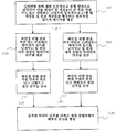
도 20은 그 일부가 도 3a, 도 3b, 도 3c, 도 3d, 도 4, 도 5a, 도 5b, 도 5c 및 도 6에 도시되어 있을 수도 있는 트윈-와이어 바인딩 장치를 코일 잠금하는 제 1 방법을 도시하는 흐름도이다. 블록 1010에서, 연속적인 길이의 와이어가 길이방향 축에 대해 일반적으로 원형 방식으로 굴곡되어 연결 섹션이 팁 섹션보다 큰 폭을 가질 수도 있는 대향하는 교번적인 일반적으로 u-형 팁 섹션 및 연결 섹션을 형성할 수 있다. 제 1 방법 실시예에서, 블록 1020에서, 와이어의 단부는 최인접 대향 팁 섹션 위로 연장하는 와이어의 길이를 남겨두는 연결 섹션 내의 점에서 절단될 수 있다. 블록 1030에서, 절단 단부는 도 3b에 도시된 바와 같이 최인접 대향 팁 섹션 주위의 루프 내로 내향으로 굴곡될 수 있다.Figure 20 shows a first method of coil locking a twin-wire binding device, some of which may be shown in Figures 3a, 3b, 3c, 3d, 4, 5a, 5b, 5c and 6 Fig. At
제 2 방법 실시예에서, 블록 1040에서, 와이어의 단부는 최인접 대향 팁 섹션을 통해 스레딩되는 와이어의 길이를 남겨두는 연결 섹션 내의 점에서 절단될 수 있다. 블록 1050에서, 절단 단부는 도 3c에 도시된 바와 같이, 최인접 대향 팁 섹션 주위의 루프 내로 외향으로 굴곡될 수 있다. 제 3 방법 실시예에서, 블록 1060에서, 와이어의 단부는 최인접 대향 팁 섹션을 통해 스레딩되는 와이어의 길이를 남겨두는 연결 섹션 내의 점에서 절단될 수 있다. 블록 1070에서, 절단 단부는 도 3d에 도시된 바와 같이, 최인접 대향 팁 섹션 주위의 루프 내로 측방향으로 굴곡될 수 있다. 상기 방법 실시예들 각각에서, 블록 1080에서, 굴곡된 와이어 단부는 그 자체로 재차 클램프되어 폐루프 링크를 형성할 수 있다.In a second method embodiment, at
도 21은 트윈-와이어 바인딩 장치의 다른 잠금 방법을 도시하는 흐름도이다. 블록 1110에서, 연속적인 길이의 와이어가 길이방향 축에 대해 일반적으로 원형 방식으로 굴곡되어 연결 섹션이 팁 섹션보다 큰 폭을 가질 수 있는 교번적인 일반적으로 u-형 팁 섹션 및 연결 섹션을 형성할 수 있다. 제 4 방법 실시예에서, 블록 1120에서, 와이어의 단부는 최인접 대향 연결 섹션 위로 연장되는 와이어의 길이를 남겨두는 팁 섹션 내의 점에서 절단될 수 있다. 블록 1140에서, 절단 단부는 최인접 대향 연결 섹션 주위의 루프 내로 내향으로 굴곡될 수 있다. 블록 1160에서, 굴곡된 와이어 단부는 도 5c에 도시된 바와 같이, 자체로 재차 클램프되어 폐루프 링크를 형성할 수 있다.Figure 21 is a flow chart illustrating another locking method of the twin-wire binding device. At
제 5 방법 실시예에서, 블록 1130에서, 와이어의 단부는 대향 연결 섹션으로 연장하거나 그를 통해 스레딩되는 와이어의 길이를 남겨두는 팁 섹션 내의 점에서 절단될 수 있다. 블록 1130에서, 절단된 단부는 대향 연결 섹션 아래로 스레딩될 수 있다(또는 대향 연결 섹션과 근접하여 굴곡됨). 블록 1150에서, 절단된 단부는 대향 연결 섹션 주위의 루프 내로 외향으로 굴곡될 수 있다. 블록 1160에서, 굴곡된 와이어 단부는 도 5b에 도시된 바와 같이, 자체로 재차 클램프되어 폐루프 링크를 형성할 수 있다.In a fifth method embodiment, at
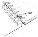
도 22a 내지 도 22d는 본 명세서에서 스테이플이라 명명된 디바이스를 사용하여, 트윈-와이어 바인딩 장치(110)의 인접 팁 섹션(160)을 잠금하기 위한 다양한 잠금 디바이스 및 방법을 도시한다. 용어 "스테이플"은 본 명세서에서 용이한 설명을 위해 사용되지만, 달리 지시되는 경우를 제외하고는, 임의의 특정 크기, 형상 또는 구성에 한정되도록 의도되는 것은 아니다. 예를 들어, 스테이플은 형상으로 형성되거나 굴곡될 수 있는 와이어 또는 와이어형 재료로 형성될 수 있지만, 다양한 재료로 제조되고 다양한 형상으로 형성되고 다양한 두께를 가질 수 있다. 금속 스테이플(1210)(도 22a 및 도 22b) 또는 플라스틱/폴리머 스테이플(1220)(도 22c 및 도 22d)이 사용될 수 있고, 또는 스테이플은 스파인 조인트(310)에 대해 상기에 열거된 재료를 포함하는 임의의 다양한 재료로 제조될 수 있다.22A-22D illustrate various locking devices and methods for locking
도면에 도시된 바와 같이, 스테이플은 인접 팁 섹션(160)에 걸칠 수 있고, 각각의 스테이플의 단부는 팁 섹션(160)의 루프를 통해 통과하고, 도시된 바와 같이 내향(또는 외향) 회전되어 팁 섹션(160)의 루프에 고정된다. 스테이플(1210, 1220)은 도시된 것보다 넓거나 좁을 수 있다(원주방향에서). 더 넓은 스테이플(1210, 1220)은 바인딩 장치(110)의 용량을 감소시키거나 그 내용물의 회전을 제한할 수 있지만, 더 강하고 그리고/또는 더 확실한 연결을 제공할 수 있다.As shown in the figure, the staples can extend over
스테이플(1210, 1220)은 바인딩 기구의 축(115)을 따라 배향된 일반적으로 직선형 후부 또는 스파인을 가질 수 있다. 각각의 스테이플(1210)은 일 경우에 약 180도 자체로 재차 만곡되거나 회전된 만곡된 팁 또는 후크부를 각 단부에 가질 수도 있어(다수의 종이의 시트를 함께 유지하는 금속 스테이플로 통상적으로 행해지는 바와 같이) 팁이 일반적으로 스파인에 평행하게 된다. 대안적으로, 원한다면 스테이플(1210, 1220)의 단부는 때때로 다수의 종이의 시트를 함께 유지하는 금속 스테이플로 행해지는 바와 같이 외향으로 회전될 수도 있다.The
스테이플(1210, 1220)은 와이어(160) 위에 예비 형성되고 스냅 결합될 수 있고, 또는 이들은 부분적으로 형성될 수 있고(즉, 팁은 완전 180도 대신에 90도와 같이, 부분적으로 굴곡될 수 있음), 이어서 팁은 루프(160)를 통해 통과한 후에 완전히 내향으로(또는 외향으로) 회전될 수 있다. 스테이플(1210, 1220)은 바인딩 장치(110)의 일 또는 양 단부에 설치될 수 있고 또는 이들은 모든 쌍의 루프(160)를 가로지르는 것을 포함하여 바인딩 장치(110)를 따라 다른 위치에 설치될 수 있다. 각각의 스테이플(1210)은 각각의 스테이플(1210)이 예를 들어 2개 초과의 루프(160)에 걸치도록 본 명세서의 도면에 도시된 바인딩 기구(110)에 대해 증가된 길이를 가질 수 있다.
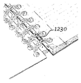
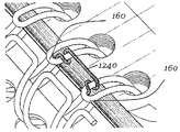
스테이플(1210, 1220)은 직사각형 단면(도 22a 내지 도 22d에 도시된 바와 같이)을 가질 수 있고 또는 원형 단면 또는 다른 형상의 단면을 가질 수 있다. 도 23a 내지 도 23c는 예를 들어 금속 또는 플라스틱 와이어와 같은 원형 단면을 갖는 다른 형태의 스테이플(1230, 1240)을 도시한다. 도 23a에서, 스테이플(1230)은 각각의 쌍의 팁 섹션(160)을 연결하는데 사용되고, 각각의 스테이플(1230)은 각각의 팁 섹션의 와이어 주위에 약 180도 권취되어 있다. 도 23b에서, 단지 최종 쌍의 팁 섹션(160)만이 스테이플(1230)에 의해 연결되어 있다. 도 23c는 그 단부가 예를 들어 360도 내지 540도 이상 또는 적어도 약 360도 팁 섹션(160)의 와이어 주위로 완전 회전을 초과하여 권취되어 있는 스테이플(1240)의 상세를 도시한다. 스테이플(1230, 1340)의 와이어/자유 단부는 도 23c에 도시된 바와 같이 인접 연관된 팁 섹션(160)을 "향해" 권취될 수 있지만, 또한 대신에 대향하는 "이격" 방향으로 권취될 수 있다.
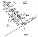
도 24a 내지 도 24d는 스테이플을 사용하여 트윈-와이어 바인딩 장치(110)의 연관된 대향 연결 섹션(170)에 팁 섹션(160)을 잠금하기 위한 다양한 구조 및 방법을 도시한다. 재차, 용어 "스테이플"은 편의상 사용된 것이고, 한정이 되도록 의도된 것은 아니며, 전술된 다양한 재료, 구조 및 배열을 포함할 수 있다. 도 24a에 도시된 바와 같이, 일 실시예에서, 스테이플(1250)은 각각의 팁 섹션(160)으로부터 바인딩 기구(110)의 축방향 연장 간극을 가로질러 인접한 대향 연결 섹션(170) 중 하나로 연장할 수 있다. 도 24b에 도시된 바와 같이, 스테이플(1250)은 단지 트윈-와이어 바인딩 기구(110)의 일 또는 양 축방향 단부에서 사용될 수 있어, 단부 팁 섹션(160)을 마지막(부분) 연결 섹션(170)(도시된 바와 같이) 또는 마지막 완전 연결 섹션(도 24b에는 도시되어 있지 않음)에 바인딩한다. 스테이플(1250)은 모든 팁 섹션(160)에 또는 일 또는 양 단부(116, 117)에 사용될 수 있고, 또는 제조 선호도에 따라 바인딩 기구(110)를 따른 임의의 위치에 배치될 수 있다. 각각의 스테이플(1250)은 그 일 단부에 한 쌍의 후크부를 갖는, 축(115)에 대해 소정 각도로 연장하는 스파인을 갖는 것으로 고려될 수 있다.24A-24D illustrate various structures and methods for locking the
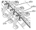
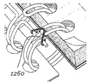
도 24c에 도시된 바와 같이, 개별 연결 섹션(170)으로부터 각각 연장하는 한 쌍의 스테이플(1260)은 단일 팁 섹션(160)에 부착될 수 있다. 이 경우에, 한 쌍의 스테이플(1260)은 팁 섹션(160)으로부터 인접 연결 섹션(170)의 모두로 바인딩 기구(110)의 축방향 간극을 가로질러 걸친다.As shown in FIG. 24C, a pair of
도 25a 내지 도 25d는 트윈-와이어 바인딩 장치(110)의 연결 섹션(170)에 팁 섹션(160)을 잠금하기 위한 다른 구조 및 방법을 도시한다. 이들 실시예는 도 22, 도 23 및 도 24의 스테이플보다 더 복잡한 스테이플, 잠금 디바이스 또는 연결 요소(1270 또는 1280)를 이용한다. 연결 요소(1270/1280)는 스테이플에 대해 상기에 개략 설명된 동일한 재료로 제조될 수 있다. 연결 요소(1270/1280)는 평면도에서 일반적으로 삼각형 형상을 가질 수 있지만, 제조 선호도에 따라 평면도에서 다른 형상을 가질 수 있다.25A-25D illustrate another structure and method for locking the
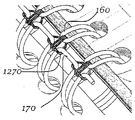
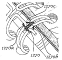
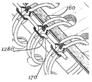
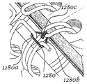
도 25a 및 도 25b에 도시된 바와 같이, 연결 요소(1270)는 축(115)에 일반적으로 평행하게 연장하고 인접 연결 섹션(170) 주위에 연결/연장하는 베이스 섹션(1270a)을 포함할 수 있다. 베이스 섹션(1270a)으로부터, 연결 요소(1270)는 베이스 섹션(1270a)이 삼각형의 밑변을 형성하고 측면 섹션(1270b)이 삼각형의 변을 형성하도록 2개의 측면 섹션(1270b)으로서 상향/원주방향/축방향으로 굴곡/연장되는데, 이는 이등변 삼각형일 수 있다. 측면 섹션(1270b)은 팁 섹션(160)의 루프를 통해 통과하고, 이어서 하향/원주방향으로 굴곡/연장되어 일반적으로 삼각형을 양분하는 중앙 섹션(1270c)을 형성한다. 중앙 섹션(1270c)은 베이스 섹션(1270a) 주위로 연장하고/주위에 권취되어 중앙 섹션(1270c)/연결 요소(1270)를 적소에 고정하는 만곡된 팁을 가질 수 있다. 연결 요소(1270)는 바인딩 기구(110)의 전체 길이를 따라 또는 그 다양한 다른 배열로 바인딩 기구(110)의 단부(116, 117)에서만 사용될 수 있다.25A and 25B, the connecting
도 25c 및 도 25d는 도 25a 및 도 25b의 연결 요소(1270)에 유사한 연결 요소(1280)를 도시한다. 특히, 도 25c 및 도 25d의 연결 요소(1280)는 도 25a 및 도 25b의 것들과 유사한 베이스 섹션(1280a) 및 측면 섹션(1280b)을 포함한다. 그러나, 도 25c 및 도 25d의 실시예에서, 중앙 섹션(1280c)은, 베이스 섹션(1280a)에서/주위에서 종료하는 대신에, 팁 섹션(160)에서/에 인접하여 종료하고, 섹션(160) 주위에 권취되고/굴곡된다. 연결 요소(1280)는 바인딩 기구(110)의 전체 길이를 따라, 또는 그 다양한 다른 배열로, 바인딩 기구(110)의 단부(116, 117)에서만 사용될 수 있다. 도 25a 내지 도 25d에 도시된 실시예에서, 연결 요소/잠금 디바이스(1270/1280)는 2개의 인접한 연결부(170)를 함께 그리고 대향 팁 부분(160)에 결합한다.Figures 25c and 25d illustrate a connecting
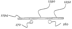
도 26a 내지 도 26d는 연결 섹션(170)의 와이어 및/또는 팁 섹션(160)의 와이어 주위에 스테이플 또는 다른 연결 요소(1210, 1220, 1230, 1250, 1260, 1270, 1280, 1290)를 부착하도록 수행될 수 있는 다양한 단계를 도시한다. 이 경우에, 스테이플/연결 요소(1290)는 도 26a에 도시된 바와 같이, 연결 요소(1290)의 스파인/주 본체와 초기에 정렬될 수 있는 단부(1292, 1294)를 갖는다. 도 26b에 도시된 바와 같이, 단부 또는 팁(1292, 1294)은 이어서 약간 하향으로 굴곡되어 와이어(170, 160) 주위에 성형을 시작할 수 있다. 도 26c에 도시된 바와 같이, 단부(1292, 1294)는 더 굴곡될 수 있고, 마지막으로 도 26d에 도시된 바와 같이, 단부(1292, 1294)는 연결 요소(1290)의 주요부에 대해 대략 180도로 굴곡될 수 있어, 단부(1292, 1294)가 일반적으로 주요부(1290)에 평행하게 되어, 스테이플/연결 요소를 와이어(160, 170)에 확실히 결합한다. 도 26a 내지 도 26d의 단계들은 도 27에 다음에 도시된 연결 요소를 형성/부착하기 위한 단계들을 구체적으로 도시하고 있지만, 이들은 또한 예를 들어 도 22a 내지 도 22d 또는 다른 실시예에 도시된 것들과 같은 스테이플을 제조하는데 있어서의 단계들을 예시하는 것으로 고려될 수 있다.Figures 26a-26d illustrate how to attach staples or other connecting
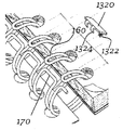
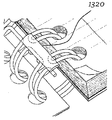
도 27a 내지 도 27d는 크림프 로크(1310, 1320)를 사용하여 트윈-와이어 바인딩 장치(110)의 연결 섹션(170)에 팁 섹션(160)을 잠금하기 위한 구조 및 방법을 도시한다. 도 27a 내지 도 27d에 도시된 크림프 로크는 도 7 내지 도 10에 도시되고 전술된 스파인 조인트(310)에 대해 특정 관점에서 유사하다. 크림프 로크(1310, 1320)는 스파인 조인트(310) 또는 본 명세서에 개시된 다른 디바이스에 대해 상기에 개략 설명된 임의의 재료로 제조될 수 있다. 크림프 로크(1310, 1320)는 몇몇 경우에 편평한 재료의 스트립으로부터 제조되고, 스탬핑되어 핑거(1312, 1314, 1322, 1324)를 남겨두고, 이어서 도 26a 내지 도 26d에 도시된 단계에 따라 절첩될 수 있다.27A-27D illustrate a structure and method for locking
크림프 후크(1310, 1320)의 재료의 탄성, 연결 섹션(170)과 팁 섹션(160) 사이의 간격 및 섹션(160, 170)을 형성하는 바인딩 기구(110)에 사용되는 바인딩 와이어의 탄성/탄력성에 따라, 크림프 로크(1310, 1320)는 완성되어 예비 형성되고 이어서 트윈-와이어 바인딩 디바이스(110) 상에/주위에 스냅 결합될 수 있고, 또는 도 26a, 도 26b, 도 26c 또는 도 26d 중 임의의 하나에 도시된 바와 같이 연결 섹션(170) 및 팁 섹션(160) 상에 크림프될 수 있다(예를 들어, 변형됨).The elasticity of the material of the crimp hooks 1310 and 1320 and the elasticity / resilience of the binding wires used in the
크림프 로크(1310, 1320)의 일 에지를 따른 핑거(1312, 1322)는 팁 섹션(160)의 루프에 결합할 수 있고, 크림프 로크(1310, 1320)의 대향 에지를 따른 핑거(1314, 1324)는 바인딩 기구(110)의 대향 측면 상의 연결 섹션(170)에 결합할 수 있다. 핑거들은 서로로부터 적절하게 이격되고 오프셋되어 팁 섹션(160) 및 연결 섹션(170) 내에 끼워질 수 있다.The
도 27a 및 도 27b에 제안된 바와 같이, 크림프 로크(1310)는 전체 바인딩 디바이스(110)를 따라 연장될 수 있어, 일 경우에 모든 또는 거의 모든 팁 섹션(160) 및 연결 섹션(170)에 결합한다. 대안적으로, 도 27d에 도시된 바와 같이, 크림프 로크(1320)는 단지 트윈-와이어 바인딩 기구(110)의 일 또는 양 단부(116, 117)에 사용될 수 있다. 전체 바인딩 기구(110)를 따라 또는 일 또는 양 단부(116, 117)에서 사용되는 대신에, 크림프는 로크(1310, 1320)는 제조 선호도에 따라 바인딩 기구(110)의 임의의 부분을 따라 유사하게 연장될 수 있다.27A and 27B, the
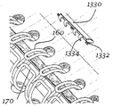
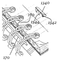
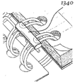
도 28a 내지 도 28d는 크림프 로크(1330, 1340)를 사용하여 트윈-와이어 바인딩 장치(110)의 연결 섹션(170)에 팁 섹션(160)을 잠금하기 위한 구조 및 방법을 도시한다. 도 28a 내지 도 28d의 크림프 로크(1330, 1340)는 도 27a 내지 도 27d에 도시되고 전술된 것들과 특정 관점에서 유사하다. 크림프 로크(1330, 1340)는 크림프 로크(1310, 1320) 및 본 명세서에 설명된 다른 구성 요소와 동일한 재료로 제조될 수 있고, 사출 성형 또는 다른 성형 방법에 의해 형성될 수 있다. 핑거(1332, 1334)는 서로로부터 적절하게 이격되고 오프셋되어 팁 섹션(160) 및 연결 섹션(170) 내로 끼워질 수 있다. 크림프 로크(1330)의 일 에지를 따른 핑거(1332)는 팁 섹션(160)의 루프에 결합되고, 반면 크림프 로크(1330)의 대향 에지를 따른 핑거(1334)는 연결 섹션(170)에 결합할 수 있다. 도 28a 내지 도 28d의 크림프 로크(1330, 1340)의 연결 요소 또는 스파인은 도 27a 내지 도 27d의 것들보다 더 두껍고 더 한정적일 수 있다.28A-28D illustrate the structure and method for locking the
도 29a 내지 도 29f는 "가드레일" 로크(1350, 1360, 1370)를 사용하여 팁 섹션(160)을 함께 연결 잠금하기 위한 구조 및 방법을 도시한다. 가드레일 로크(1350, 1360, 1370)는 스파인 조인트(310)를 포함하는 본 명세서에 설명된 다양한 다른 구성 요소의 동일한 재료로 제조될 수 있고, 사출 성형, 스탬핑 또는 다른 성형 방법에 의해 형성될 수 있다. 도 29a에 도시된 바와 같이, 가드레일 로크(1350)는 한 쌍의 대향하는 길이방향 쌍 또는 레일을 갖는 정면도에서 좁은 또는 세장형 루프 형상을 가질 수 있다. 로크(1350)는 그 하나의 레일/측면을 따라 위치된 복수의 내향 연장 핑거(1352)와, 그 다른 레일/측면을 따라 위치된 다른 복수의 내향 연장 핑거(1353)를 가질 수 있다. 각각의 핑거(1352, 1353)는 가드레일 로크(1350) 내의 간극의 높이의 대략 절반 또는 절반 미만 내향으로 연장될 수 있다.29A-29F illustrate a structure and method for coupling and locking
가드레일 로크(1350)는 팁 와이어(160)의 하나 이상의 쌍 주위로 연장하도록 충분히 길고, 하나 이상의 핑거(1352)는 팁 섹션(160)의 중심 내에 끼워진다. 핑거(1353)는 하나 이상의 핑거(1353)가 팁 섹션(들)(160)의 외부 주위에 끼워져서 팁 섹션(160)의 각각의 와이어 섹션이 한 쌍의 핑거(1353, 1352) 사이에 포획되도록 위치된다.
가드레일 로크(1350)는 바인딩 기구(110)의 축방향 연장 간극 내로 가드레일 로크(1350)를 배치하고, 이어서 도 29a 및 도 30에 도시된 바와 같이, 가드레일 로크(1350)가 팁 섹션(160)에 결합할 때까지 가드레일 로크(1350)를 원주방향으로 이동함으로써 이용될 수 있다. 가드레일 로크(1350)가 팁 섹션(160)의 단부 위에 배치된 후에, 가드레일 로크(1350)는 함께 가압될 수 있어, 레일을 서로를 향해 압착하여, 가드레일 로크의 레일들 사이에 팁 섹션(160)을 개재하는 폐쇄된 가드레일 로크(1350')를 형성한다(도 29b 참조). 가드레일 로크(1350)는 팁(1352, 1353)이 대향 레일에 결합할 때까지 압축될 수 있다. 팁(1352, 1353)은 마찰력에 의해 팁 섹션(160)을 파지하고, 그리고/또는 팁 섹션(160)이 이격되어 스프링력에 의해 그 사이에 팁 섹션(1352)을 파지하도록 치수 설정되고 구성될 수 있다.The
가드레일 로크(1350)는 그 잠금된 위치(도 29a)와 잠금 해제된 위치(도 29b) 사이에서 수동으로 이동 가능하여 사용자가 다양한 바인딩 기구에 가드레일 로크(1350)를 장착하고 그리고/또는 탈착할 수 있게 하도록 구성될 수 있다. 대안적으로, 가드레일 로크(1350)는 충분한 강성을 갖고 그리고/또는 가드레일 로크(1350)가 잠금된 또는 잠금 해제된 위치 사이로 수동으로 이동할 수 없도록 충분한 잠금력이 요구된다.The
일 경우에, 가드레일 로크(1350')는 전체 바인딩 장치(110)를 따라 연장되어, 모든 또는 거의 모든 팁 섹션(160)을 결합할 수 있다. 대안적으로, 가드레일 로크(1350')는 트윈-와이어 바인딩 기구(110)의 단지 일 또는 양 단부에서 사용될 수 있고, 또는 제조 선호도에 따라 바인딩 기구(110)의 임의의 부분을 따라 연장될 수 있다.The guardrail lock 1350 'may extend along the entire
도 29c 및 도 29d는 팁 섹션(160)의 중심에 끼워지도록 구성된 하나 이상의 핑거(1362, 1363)를 갖는, 하나 이상의 쌍의 팁 와이어(160) 주위로 연장하기에 충분히 긴 좁은 루프의 형태의 가드레일 로크(1360)를 도시한다. 본 실시예에서, 가드레일 로크(1360)가 그 잠금된 위치(도 29d)로 이동될 때, 가드레일 로크(1360')는 가드레일 로크(1360')의 레일들 사이에 팁 섹션(160)을 개재한다. 핑거(1362, 1363)는 도시된 바와 같이 함께 만날 수 있고, 또는 가드레일 로크(1360')가 압축될 때 이격될 수 있다.Figures 29c and 29d show a guard in the form of a narrow loop long enough to extend around one or more pairs of
도 29e 및 도 29f는 하나 이상의 쌍의 팁 와이어(160) 주위로 연장하기에 충분히 긴 좁은 루프의 형태의 다른 가드레일 로크(1370)를 도시한다. 팁 섹션(160)의 단부들 위에 가드레일 로크(1370)를 배치한 후에, 가드레일 로크의 길이방향 측면/레일(1372, 1373)은 가드레일 로크(1370')의 길이방향 측면(1372, 1373) 사이에 팁 섹션(160)을 개재하는 도 29f에 도시된 폐쇄된 가드레일 로크(1370')를 형성하도록 함께 가압될 수 있다. 도 29e 및 도 29f의 실시예에서, 길이방향 측면(1372)은 팁 섹션(160)의 쌍 사이의 영역에서 내향으로 변형되고, 길이방향 측면(1373)은 팁 섹션(160)의 간극 내로 내향으로 변형된다. 성형 도구(도시 생략)가 폐쇄된 가드레일 로크(1370')를 원하는 형상으로 변형하는데 사용될 수 있다. 도 30은 가드레일 로크(1350')의 기다란 측면이 팁 섹션(160)에 대해 폐쇄되고, 핑거(1352)가 팁 섹션(160) 내부에 핑거(1353)가 팁 섹션(160) 바로 외부에 있는, 트윈-와이어 바인딩 장치(110) 상에 설치된 폐쇄된 가드레일 로크(1350')의 상세도를 도시한다.29E and 29F illustrate another
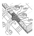
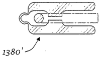
도 31a 내지 도 31c는 팁 섹션(160)의 단부들 상에 결합되도록 구성된 로크 또는 잠금 디바이스(1380)를 도시한다. 로크(1380)는 상부 부분(1385) 및 하부 부분(1386)이 힌지(1384)에 의해 함께 피벗식으로 결합된 상태로 형성될 수 있다(예를 들어, 사출 성형에 의해). 일 경우에, 힌지(1384)는 힌지 기능성을 제공하기 위해 상부 부분(1385) 및 하부 부분(1386)보다 얇고 그리고/또는 약한 재료로 제조된다. 로크(1380)는 종이(150) 또는 다른 내용물이 바인딩 기구(110) 내에 보유되는 것을 보장하는 기능을 하는 구멍(140)의 에지를 지나 축방향으로 연장하는 하나 이상의 축방향 연장 날개 섹션(1382)을 가질 수 있다. 돌기(1387)는 상부 부분(1385)의 하부면 및/또는 하부 부분(1386)의 상부면 상에 위치될 수 있고, 이 돌기(1387)는 팁 섹션(160)의 와이어 내부 또는 주위에 끼워지도록 구성된다.Figs. 31A-C illustrate a locking or
로크(1380)를 적소에 장착하기 위해, 로크(1380)는 도 31b에 도시된 바와 같이 위치된다. 상부 부분(1385) 및/또는 하부 부분(1386)은 도 31c에 도시된 바와 같이 팁 섹션(160) 상에서 힌지(1384)에 대해 함께 절첩된다. 상부 부분(1385) 및 하부 부분(1386)은 이어서 초음파 용접 또는 열 용접에 의해, 또는 접착제에 의해 스냅-끼워맞춤(도시 생략)과 같은 상호 잠금부에 의해 함께 결합될 수 있고, 또는 성형된 로크(1380)는 따뜻하고 유연성이 있으면서 도포될 수 있고, 힌지부(1384)가 성형된 로크(1380)를 적소에 유지하기 위해 충분히 강성이 되도록 냉각될 수도 있다.To lock 1380 in place,
로크(1380)(및 예를 들어 도 31 및 도 32에서 이하에 개시된 다른 로크)는 사용자가 로크(1380)를 다양한 바인딩 기구에 결합하고 그리고/또는 결합 해제하게 하기 위해 잠금된 위치와 비잠금된 위치 사이에서 수동으로 이동 가능하도록 구성될 수 있다. 대안적으로, 로크는 더 큰 보안을 제공하도록 수동으로 이동 가능하지 않을 수도 있다. 도 31a에 도시된 바와 같이, 성형된 로크(1380')(뿐만 아니라, 예를 들어 도 31 및 도 32에서 이하에 설명된 로크)는 예를 들어 트윈-와이어 바인딩 장치(110)의 일 또는 양 단부(116, 117)에서 단일 팁 섹션(160)에 부착될 수 있고, 또는 바인딩 장치(110)의 길이를 따라 다른 위치에 부착될 수 있다. 성형된 로크(1380')(뿐만 아니라 도 31 및 도 32에서 이하에 설명된 로크)는 단지 단일의 팁 섹션(160)을 커버할 수 있고 또는 다수의 팁 섹션(도시 생략) 위에서 연장할 수도 있다.Locks 1380 (and other locks, such as those described below in Figures 31 and 32) may be used to lock and unlock
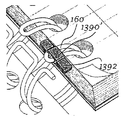
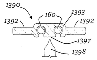
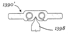
도 31d 내지 도 31f는 팁 섹션(160)의 와이어들 중 하나 또는 모두를 수용하기 위한 홈(1393)을 갖는 스냅-온 구성 요소로서 로크/잠금 디바이스(1390)를 도시한다. 각각의 홈(1393)은 그 내부에 팁 섹션(160)의 와이어를 밀접하게 수용하도록 치수 설정될 수 있고, 저부 개구/홈(1393)/로크(1390)가 팁 섹션(160)의 와이어를 수용하기 위해 변형되고 이어서 그 내부에 팁 섹션(160)을 보유하기 위해 그 원래 비변형된 형상으로 복귀하도록 와이어의 직경보다 작은 저부 개구를 가질 수 있다. 그러나, 몇몇 경우에, 저부 개구는 로크(1390)가 팁 섹션(160) 상에 용이하게 배치될 수 있도록 팁 섹션(160)의 와이어의 직경보다 작지 않다. 로크(1390)는 홈(1393) 사이에 위치되고 팁 섹션(160)의 와이어 사이에 끼워지도록 구성된 중앙 돌기(1397)를 포함할 수 있다. 로크(1390)는 종이(150) 또는 다른 구성 요소가 바인딩 기구(110)로부터 분리되는 것을 방지하기 위해 연관된 개구(140)를 지나 축방향으로 연장하는 하나 이상의 축방향 연장 날개 섹션(1392)을 또한 포함할 수 있다.Figures 31d-31f illustrate a lock /
로크(1390)를 사용하기 위해, 로크는 도 31e에 도시된 바와 같이, 먼저 팁 섹션(들)(160) 상의 적소에 스냅 고정되거나 위치된다. 성형 도구(1398)(도 31f)가 성형된 로크(1390)에 대해/내로, 예를 들어 돌기(1397) 내로 가압될 수 있다. 성형 도구(1398)는 도구(1398) 및/또는 돌기(1397)의 가열에 의해 또는 가열 없이 부착될 수 있다. 도구(1398)는 도 31f에 도시된 바와 같이 돌기 내로 압박되어, 이에 의해 재료를 팁 섹션(160)의 와이어 및 홈(1393) 아래로/내로 측방향으로 변위시켜, 로크(1390)를 적소에 잠금한다.To use the
도 32a 및 도 32b는 팁 섹션(160)의 단부들 상에 끼워지도록 구성된 2 부분 로크(1410)를 도시한다. 2 부분 성형된 로크(1410)는 2개의 개별 부분(1416, 1417)을 포함하는 스냅-온 구성 요소로서 형성될 수 있다(예를 들어, 사출 성형에 의해). 일 부분(1416/1417)은 연관된 코일 팁(160)의 제 1(상부) 측 상에 위치되도록 구성되고, 다른 부분(1417)은 팁(160)의 제 2(하부) 측 상에 위치되도록 구성된다. 각각의 부분(1416, 1417)은 팁(160)의 루프 내에 위치되도록 구성된 중심 돌기를 포함할 수 있다.32A and 32B illustrate a two-
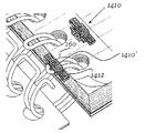
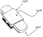
부분(1416/1417)은 상부(160) 상에 장착될 때 2개의 부분(1416, 1417)을 함께 유지하기 위한 스냅-결합 특징부 또는 다른 상호 연결 특징부(도시 생략)와 같은 상보형 특징부를 가질 수 있다. 대안적으로 또는 부가적으로, 접착제, 초음파 용접 및/또는 열 용접이 2개의 부분(1416, 1417)을 함께 유지하는데 사용될 수 있다. 로크(1410) 및/또는 하나 또는 양 부분(1416/1417)은 종이(150) 또는 다른 내용물이 팁 섹션(160)으로부터 탈락하는 것을 방해하는 기능을 하는 하나 이상의 축방향 연장 날개 섹션(1412)을 포함할 수 있다.
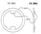
도 33a 내지 도 33d는 변형되어 팁 섹션(160)의 단부 상에 끼워질 수 있는 크림프 가능 또는 변형 가능한 와셔 로크(1420)의 형태의 바인딩 기구(110) 상에 구성 요소를 보유하기 위한 다른 잠금 디바이스를 도시하고 있다. 와셔 로크(1420)는 금속, 폴리머 또는 플라스틱(예를 들어, 스탬핑 또는 사출 성형에 의해) 또는 스파인 조인트(310)를 포함하는 본 명세서에 개시된 다른 디바이스를 위한 재료로부터 형성될 수 있다. 와셔 로크(1420)는 도 33a에 도시된 바와 같이 정면도/평면도에서 일반적으로 환형/원형일 수 있지만, 또한 그 내부에 중앙 개구가 형성되어 있는 원형 이외의 다른 형상을 갖거나 다른 형상일 수 있다. 와셔 로크(1420)는 중앙 개구 내로 반경방향 내향으로 연장하는 하나 이상의 돌기/치형부(1422)를 포함할 수 있다. 초기에 형성될 때, 와셔 로크(1420)는 치형부(1422)가 도 33b의 측면도에 도시된 바와 같이 약간 평면 외에 있을 수 있는 것을 제외하고는, 일반적으로 편평하고 평면형일 수 있다. 그러나, 원한다면, 치형부(1422)는 또한 편평형 및 평면형일 수 있다.33A-33D illustrate another locking device (not shown) for retaining a component on a
와셔 로크(1420)를 사용하기 위해, 와셔 로크는 팁 섹션(160)의 단부 상에 배치되고 팁 섹션(160) 위에서 대략 180도로 자체로 굴곡될 수 있어, 와셔 로크(1420)를 대략적으로 측면도에서 "C" 형상으로 또는 평면도에서 반원형 형상으로 형성한다. 와셔 로크(1420)가 이 방식으로 변형될 때, 치형부(1422)는 서로 결합되거나 서로 밀접하여 위치되어, 이에 의해 치형부(1422)를 연관 팁 섹션(160)의 루프 내로 잠금한다. 치형부(1422)의 각형성된 특성은 와셔 로크(1420)가 굴곡될 때 치형부(1422)가 더 편향되어 치형부(1422)가 서로 직접 결합할 필요성을 회피하고 와셔 로크(1420)의 편향에 대한 과도한 저항을 제공하는 것을 보장하는 것을 돕는다. 와셔 로크(1420)가 변형될 때, 이는 상부 부분 및 상부 부분과 일반적으로 정렬된 하부 부분을 포함할 수 있고(도 33c에 가장 양호하게 도시된 바와 같이), 여기서 상부 부분 및 하부 부분은 바인딩 장치(110)의 축에 일반적으로 평행하게 연장하는 절첩 라인 또는 절첩된 영역에 의해 분리된다.The washer lock may be disposed on the end of the
도 33d에 도시된 바와 같이, 축(115)에 평행하게 연장하는 와셔 로크(1420)의 부분은 종이(150) 또는 다른 구성 요소 내의 개구(140)를 지나 연장한다. 이 방식으로, 와셔 로크(1420)는 팁 섹션(160)에 확실하게 결합되고 팁 섹션(160)의 단부를 효과적으로 확장하여 내용물이 팁 섹션(160)으로부터 탈락하는 것을 방지한다.33D, a portion of the
도 33d에 도시된 바와 같이, 굴곡된 와셔 로크(1420')(뿐만 아니라, 도 33, 도 34 및 도 35에 도시된 다른 실시예)는 예를 들어 트윈-와이어 바인딩 장치(110)의 일 또는 양 단부(116, 117)에서 단일 팁 섹션(160)에 부착될 수 있고, 또는 바인딩 장치(110)의 길이를 따라 또는 다수의 팁 섹션(160)을 가로질러 다른 위치에서 하나 이상의 팁 섹션(160)에 부착될 수 있다.As shown in FIG. 33D, the bent washer lock 1420 '(as well as other embodiments shown in FIGS. 33, 34, and 35) may be used, for example, May be affixed to a
도 33e는 비교적 짧은 브리지(1424)에 의해 연결된 2개의 섹션(1420)을 포함하는 비변형된 와셔 로크를 도시한다. 도 33e에 도시된 디바이스는 2개의 인접한 팁 섹션(160) 상에 사용될 수 있고 일반적으로 도 33a 내지 도 33d에 도시되고 전술된 바와 같이 이용될 수 있다. 와셔 로크는 원하는 바에 따라 2개 초과의 인접 팁 섹션(160)을 연결하기 위한 2개 초과의 섹션(1420)을 또한 포함할 수 있다.FIG. 33E shows a non-deformed washer lock that includes two
도 33f는 도 33e의 것에 비교하여 더 긴 브리지(1425)에 의해 연결된 2개의 섹션(1420)을 포함하는 와셔 로크를 도시한다. 이 구성은 더 이격된 인접한 팁 섹션(160)을 갖는 바인딩 기구와 조합하여 사용될 수 있고, 또는 비인접 팁 섹션(160)과 조합하여 사용될 수 있다. 도 33f의 와셔 로크는 원하는 바에 따라 2개 초과의 팁 섹션(160)을 연결하기 위한 2개 초과의 섹션(1420)을 포함할 수 있다.Figure 33f illustrates a washer lock that includes two
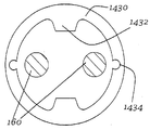
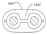
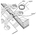
도 34a 내지 도 34c는 팁 섹션(160)의 단부들 상에 끼워지도록 구성된 크림프 가능한 와셔 로크(1430)를 도시한다. 크림프 가능한 와셔 로크(1430)는 하나 이상의 치형부(1432)를 포함하여, 도 33a 내지 도 33d에 도시된 와셔 로크(1420)에 형상, 재료 및 구조가 유사할 수 있다. 도 34의 와셔 로크(1430)는 와셔 로크(1430)가 크림프 중에 더 용이하게 또는 더 많은 제어를 갖고 변형되는 것을 가능하게 하기 위해 와셔 로크(1430) 상의 하나 이상의 위치에 위치된 릴리프 개구(1434)를 포함할 수 있다. 릴리프 개구(1434)는 서로 180도 대향하고, 치형부(1432)로부터 약 90도 오프셋될 수 있다.34A-C illustrate a
도 34a의 크림프 가능한 와셔 로크(1430)를 사용하기 위해, 와셔 로크(1430)는 팁 섹션(160)의 단부 상에 배치되고 이어서 일반적으로 와셔 로크(1430)의 와셔 로크(1430)의 평면 내에서 압축되거나 크림프될 수 있다[예를 들어, 반경방향으로 와셔 로크(1430)에 압축력을 인가함으로써). 와셔 로크(1430)가 이 방식으로 압축될 때, 와셔 로크(1430)는 세장형 형상으로 이동되고 치형부(1432)가 서로 접근하고 팁 섹션(160)에서 루프에 진입하여, 이에 의해 팁 섹션(160)을 파지하고 팁 섹션(160)의 단부를 효과적으로 확장하여 내용물이 팁 섹션(160)으로부터 탈락하는 것을 방지한다.The
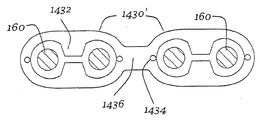
도 34d는 도 34a 내지 도 34c의 것과 유사하지만, 브리지(1436)에 의해 연결되고 2개의 팁 섹션(160) 상에 사용을 위해 적합한 2개의 섹션(1430)을 포함하는 크림프 가능한 와셔 로크를 도시한다. 도 34e는 크림프 후에 와셔 로크를 도시한다. 크림프 가능한 와셔 로크는 원하는 바에 따라 2개 초과의 섹션(1430)을 포함할 수 있다.Figure 34d shows a crimpable washer lock similar to that of Figures 34a-34c but including two
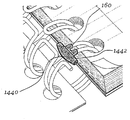
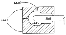
도 35a 및 도 35b는 팁 섹션(160)의 단부 상에 끼워지도록 구성된 로크(1440)를 도시한다. 성형된 로크(1440)는 플라스틱, 폴리머, 금속 또는 본 명세서에 개시된 다른 디바이스를 위해 본 명세서에 설명된 다른 재료로부터 형성될 수 있다(예를 들어, 사출 성형에 의해). 로크(1440)는 도 35a에 도시된 예시적인 형태를 포함하는 다양한 형상 또는 형태를 가질 수 있고, 내용물이 바인딩 기구(110) 상에 잔류하는 것을 보장하기 위해 하나 이상의 축방향 연장 날개부(1442)를 가질 수 있다.35A and 35B illustrate a
도 35b의 단면도에 도시된 바와 같이, 성형된 로크(1440)는 하나 이상의 팁 섹션(160) 상에 몰드(1445)를 배치하고 몰드(1445)의 하나 이상의 탕구(1446)를 통해 유체 상태의 사출 가능 재료(열가소성 재료, 폴리머, 플라스틱 또는 금속과 같은)를 사출하여 팁 섹션(160) 주위에 성형된 로크(1440)를 형성함으로써 형성될 수 있다. 몰드(1445)는 이어서 제거되어, 성형된 로크(1440)를 뒤에 남겨두어 냉각 및 경화시킨다. 성형된 로크(1440)는 트윈-와이어 바인딩 장치(110)의 일 또는 양 단부에 위치될 수 있고, 또는 바인딩 장치(110)를 따라 다른 위치에서 하나 이상의 팁 섹션(160) 상에 위치될 수도 있다.35B, the molded
도 36a 내지 도 36e는 트윈-와이어 바인딩 장치(110)의 팁 섹션(160) 상의 예비 형성된 말단 또는 돌기부(1450)를 도시한다. 팁 섹션(160)은 종이(150) 또는 다른 내용물 내의 구멍을 통해 통과하기에 충분히 밀접하게 함께 이격되거나 구멍(140)의 직경보다 작은 총 두께를 갖는 일반적으로 평행한 2개의 와이어 세그먼트로 제조된 내용물 지지 또는 저장 섹션(161)을 각각 가질 수 있다. 대조적으로, 예비 형성된 말단부(1450)는 내용물 내의 구멍(140)보다 또는 내용물 지지 섹션(161)보다, 축방향 연장 방향 및 비변형된/본래의 상태에서 더 넓을 수 있다.Figs. 36A-36E illustrate preformed ends or
도 36b에 도시된 바와 같이, 예비 형성된 말단부(1450)는 말단각 또는 선단 에지(1452)[예비 형성된 팁(160)의 단부에서] 및 전이각 또는 후단 에지(1454)[팁(160)의 주요부 내로 재차 이어지는]를 갖고 형성될 수 있다. 말단각(1452)은 전이각(1454)보다 더 예각일 수 있다. 예를 들어, 말단각(1452)은 비교적 예각일 수 있어 팁(160)이 종이(150) 또는 다른 내용물 내로 비교적 용이하게 삽입되지만, 그로부터 제거에 저항하게 된다. 일 경우에, 말단각(1452)은 약 10 내지 약 45도(반경방향 평면 또는 원주방향 라인에 대해)의 범위일 수 있고, 전이각(1454)은 도 37d에 도시된 것과 같이 약 30 내지 약 120도의 범위이다. 그러나, 본 명세서에 제공된 이들 각도 및 각도의 범위는 한정의 범위로서가 아니라 단지 예로서 의도된 것이라는 것이 이해되어야 한다. 더 예각의 말단각(1452)은 예비 형성된 말단부(1450)가 내용물(150) 내의 구멍을 통해 통과하는 것을 더 용이하게 할 수 있고, 반면에 덜 예각인 전이각(1454)은 내용물(150)이 팁 섹션(160)으로부터 탈출하는 것을 더 어렵게 할 수 있다. 말단부(1450)는 바인딩 코일의 임의의 다른 부분의 축방향 폭보다 큰 축방향 폭을 가질 수 있다.As shown in Figure 36B, the preformed
도 36c 내지 도 36e는 내용물(150) 내로 삽입되는 팁 섹션(160)을 도시하는 시퀀스를 도시한다. 도 36c는 예비 형성된 말단부(1450)가 비변형된/본래의 상태에 있는 팁 섹션(160)을 도시한다. 도 36d는 내용물 아이템(150)에 결합하여 함께 압축되는 선단 에지(1450)를 도시한다. 내용물 지지 섹션(161)은 또한 함께 압축될 수 있다. 팁 섹션(160)은 팁 섹션(160)을 정렬된 개구(140) 내에 삽입하는 것이 삽입 중에 팁 섹션(160)의 편향을 야기하도록 충분히 변형 가능할 수 있다. 대안적으로, 몇몇 경우에, 팁 섹션(160)은 삽입 중에 외력에 의해 함께 압착될 수 있다. 도 36e는 이들이 그 본래의/비변형된 구성으로 탄성 복원되어 이제 종이(150) 및 다른 내용물을 팁 섹션(160) 상에 확실하게 유지한 후에 팁 섹션(160) 및 예비 형성된 말단부(1450)를 도시한다.Figures 36c-e illustrate a sequence illustrating the
도 37a 내지 도 37e는 도 36에 도시되고 전술된 실시예와 유사하고 동일한 이득을 제공할 수 있는 트윈-와이어 바인딩 장치(110)의 팁 섹션(160) 상의 말단부(1460)를 도시한다. 대안적으로, 도 37(및/또는 도 36)에 도시된 팁 섹션은 팁 섹션(160)이 종이(150) 및 다른 내용물 아이템의 구멍(140)을 통해 통과한 후에 원하는 형상으로 형성될 수 있다. 예를 들어, 팁 섹션(160)은 팁 섹션(160)이 종이(150) 및 다른 내용물 아이템의 구멍(140)을 통해 통과함에 따라 초기에 도 37b에 도시된 형상을 가질 수 있다. 팁 섹션(160)이 구멍(140)을 통해 완전히 통과된 후에, 팁 섹션(160)은 이어서 도 37a 및 도 37c 내지 도 37e, 도 36에 도시된 형상 또는 다른 형상으로 형성될 수 있다. 팁 섹션은 기계적 로봇식 압착 성형 핑거 또는 페이지(150)를 통해 삽입 후에 팁 섹션(160) 내에 도달하여 이를 형성할 수 있는 다른 성형 디바이스에 의해 성형될 수 있다. 후-형성 말단부(1460)는 내용물 지지 섹션(161)보다 크고 그리고/또는 구멍(140)보다 길게 제조되어 페이지(150)가 팁 섹션(160)으로부터 탈락하는 것을 방지하거나 제한할 수 있다.37A-37E illustrate a
도 37c는 팁(160)이 내용물(150) 내의 구멍을 통해 통과된 후에 형성된, 삼각형 또는 화살표 형상을 갖는 후-형성 말단부(1462)를 도시한다. 도 37d는 다른 "화살표" 형상 후-형성 말단부(1464)를 도시하고, 도 36e는 t-형 후-형성 말단부(1466)를 도시한다. 이들이 내용물(150)이 팁 섹션(160)으로부터 탈락하는 것을 방지하거나 방해하기 위해 충분히 팁 섹션(160)의 단부를 확장하거나 넓히면, 다른 형상이 또한 사용될 수도 있다.Figure 37c shows a
트윈-와이어 또는 나선형 바인딩을 잠금하기 위한 본 명세서에 설명된 방법 및 구조는 서로 조합하여 사용될 수 있다는 것이 이해되어야 한다. 예를 들어, 땜납 용접이 단부들 사이의 하나 이상의 위치에서 부착된 코움-로크로 바인딩의 각각의 단부에 사용될 수 있다. 다른 예로서, 플라스틱 코일 스파인 조인트 단부 사이의 하나 이상의 점에서 사용된 상태로, 금속 코일 스파인 조인트가 바인딩의 단부들에 사용될 수 있다.It should be understood that the methods and structures described herein for locking twin-wire or spiral binding can be used in combination with one another. For example, a solder weld may be used at each end of the comb-lock binding attached at one or more locations between the ends. As another example, with one or more points between the plastic coil spine joint ends, a metal coil spine joint may be used at the ends of the binding.
본 개시 내용은 단지 상기 예에만 또는 단지 지정된 바람직한 실시예에만 한정되는 것으로서 숙독되어서는 안된다.The present disclosure should not be read as being limited solely to the above examples or to only the preferred embodiments specified.
Claims (115)
일반적으로 동축으로 배열된 복수의 바인딩 코일들을 갖는 형상으로 와이어를 형성하는 단계로서, 각각의 상기 바인딩 코일은 팁 내에서 종료하는 일반적으로 평행한 한 쌍의 와이어들을 포함하고, 각각의 상기 바인딩 코일은 상기 바인딩 장치의 축에 일반적으로 평행하게 연장하는 연결부에 의해 인접 바인딩 코일에 결합되는, 상기 와이어 형성 단계; 및
적어도 하나의 바인딩 코일을 그 자신에 또는 연결부에 원주방향으로 부착하는 단계를 포함하는 바인딩 장치 제조 방법.A method of manufacturing a binding device,
Forming a wire in a shape that is generally coaxially arranged with a plurality of binding coils, each of said binding coils comprising a pair of generally parallel wires terminating in a tip, each of said binding coils Said wire forming step being coupled to an adjacent binding coil by a connection extending generally parallel to an axis of said binding device; And
Attaching at least one binding coil to itself or to the connection in a circumferential direction.
트윈-와이어 장치를 포함하고, 상기 트윈-와이어 장치는
길이방향 축에 대해 일반적으로 원형 방식으로 굴곡되어 대향하는 교번적인 일반적으로 u-형 팁 섹션들 및 연결 섹션들을 형성하는 연속적인 길이의 와이어를 포함하고, 상기 연결 섹션들은 상기 팁 섹션들보다 큰 폭을 갖고, 상기 트윈-와이어 장치의 단부들은 대향 팁 섹션으로 연장하는 와이어의 길이를 남겨두고 상기 대향 팁 섹션 주위의 루프 내로 굴곡되고 폐루프 링크를 형성하도록 그 자체로 재차 클램프되는 연결 섹션 내의 점에서 절단되는 잠금 장치.A locking device for a twin-wire binding device,
Twin-wire device, said twin-wire device comprising:
Shaped tip sections and successive lengths of wire that are generally circularly curved and opposed to the longitudinal axis and form opposing generally u-shaped tip sections and connection sections, the connection sections having a width greater than the width of the tip sections Wherein ends of the twin-wire device are bent into a loop around the opposing tip section, leaving the length of the wire extending to the opposing tip section and being clamped again by itself to form a closed loop link Locking device to be cut.
트윈-와이어 장치를 포함하고, 상기 트윈-와이어 장치는
길이방향 축에 대해 일반적으로 원형 방식으로 굴곡되어 대향하는 교번적인 일반적으로 u-형 팁 섹션들 및 연결 섹션들을 형성하는 연속적인 길이의 와이어를 포함하고, 상기 연결 섹션들은 상기 팁 섹션들보다 큰 폭을 갖고, 상기 트윈-와이어 장치의 단부들은 대향 연결 섹션으로 연장하는 와이어의 길이를 남겨두고 상기 대향 연결 섹션 주위의 루프 내로 굴곡되고 폐루프 링크를 형성하도록 그 자체로 재차 클램프되는 팁 섹션 내의 점에서 절단되는 잠금 장치.A locking device for a twin-wire binding device,
Twin-wire device, said twin-wire device comprising:
Shaped tip sections and successive lengths of wire that are generally circularly curved and opposed to the longitudinal axis and form opposing generally u-shaped tip sections and connection sections, the connection sections having a width greater than the width of the tip sections Wherein the ends of the twin-wire arrangement are bent into a loop around the opposing connection section leaving the length of the wire extending to the opposing connection section and being clamped again by itself to form a closed loop link Locking device to be cut.
상기 바인딩 장치의 부분들에 일반적으로 원주방향으로 결합하는 잠금 디바이스를 포함하는 바인딩 장치 시스템.Each of the binding coils comprising a pair of generally parallel wires terminating in a tip, each of the binding coils comprising a plurality of binding coils, generally coaxially arranged, A binding device coupled to the adjacent binding coil by a connecting portion extending in parallel; And
And a locking device generally circumferentially engaging portions of the binding device.
트윈-와이어 장치를 포함하고, 상기 트윈-와이어 장치는
길이방향 축에 대해 일반적으로 원형 방식으로 굴곡되어 대향하는 교번적인 일반적으로 u-형 팁 섹션들 및 연결 섹션들을 형성하고, 상기 연결 섹션들은 상기 팁 섹션들보다 큰 폭을 갖는 연속적인 길이의 와이어; 및
스파인 섹션을 따라 모두 연결된 한 쌍의 연결 후크 섹션들 사이에 배치된 팁 후크 섹션에 의해 대향된 한 쌍의 연결 후크 섹션들로 구성된 코일 스파인 조인트로서, 상기 한 쌍의 연결 후크 섹션들은 대응 인접 연결 섹션들을 협동적으로 결합하도록 적용되고, 상기 팁 후크 섹션은 대응 대향 팁 섹션을 협동적으로 결합하도록 적용되는, 코일 스파인 조인트를 포함하는 잠금 장치.A locking device for a twin-wire binding device,
Twin-wire device, said twin-wire device comprising:
Shaped generally generally u-shaped tip sections and connecting sections bent in a generally circular fashion relative to the longitudinal axis, said connecting sections having a continuous length of wire having a width greater than said tip sections; And
A coiled spine joint comprising a pair of connecting hook sections opposed by a tip hook section disposed between a pair of connecting hook sections all connected along a spine section, Wherein said tip hook section is adapted to cooperatively engage corresponding counter-tip sections. ≪ Desc / Clms Page number 17 >
스파인 섹션을 따라 연결된 적어도 하나의 팁 후크 섹션에 의해 대향된 적어도 하나의 연결 후크 섹션을 포함하고, 상기 연결 후크 섹션은 트윈-와이어 바인딩 장치의 대응 연결 섹션을 결합하도록 적용되고, 상기 팁 후크 섹션은 상기 트윈-와이어 바인딩 장치의 팁 섹션을 결합하도록 적용되는 코일 스파인 조인트.A coil spine joint for use with a twin-wire binding device,
At least one connecting hook section opposed by at least one tip hook section connected along a spine section, the connecting hook section being adapted to engage a corresponding connecting section of a twin-wire binding device, the tip hook section A coil spine joint adapted to engage a tip section of the twin-wire binding device.
스파인 및 상기 스파인으로부터 이격하여 외향으로 연장하는 복수의 핑거 요소를 포함하고, 각각의 상기 핑거 요소는 잠금 디바이스를 상기 바인딩 장치에 결합하기 위해 바인딩 코일의 와이어들의 쌍 사이에 끼워지도록 구성되는 잠금 디바이스를 포함하는 바인딩 장치 시스템.Each of the binding coils comprising a pair of generally parallel wires terminating in a tip, each of the binding coils comprising a plurality of binding coils arranged in parallel to the axis of the binding device The binding device being coupled to an adjacent binding coil by an extending connection; And
A spine and a plurality of finger elements extending outwardly from the spine, each finger element comprising a locking device configured to fit between a pair of wires of the binding coil to couple the locking device to the binding device Containing binding device system.
트윈-와이어 장치를 포함하고, 상기 트윈-와이어 장치는
길이방향 축에 대해 일반적으로 원형 방식으로 굴곡되어 대향하는 교번적인 일반적으로 u-형 팁 섹션들 및 연결 섹션들을 형성하고, 상기 연결 섹션들은 상기 팁 섹션들보다 큰 폭을 갖는 연속적인 길이의 와이어; 및
스냅-인 코움 로크 구성 요소(snap-in comb lock component)를 포함하고, 상기 스냅-인 코움 로크 구성 요소는
스파인 요소; 및
상기 스파인 요소로부터 돌출하는 걸림 장치를 각각 포함하는 복수의 핑거 요소들로 구성되는 잠금 장치.A locking device for a twin-wire binding device,
Twin-wire device, said twin-wire device comprising:
Shaped generally generally u-shaped tip sections and connecting sections bent in a generally circular fashion relative to the longitudinal axis, said connecting sections having a continuous length of wire having a width greater than said tip sections; And
A snap-in comb lock component, comprising: a snap-in comb lock component
Spine element; And
And a plurality of finger elements each comprising a latching device projecting from the spine element.
스파인 요소; 및
상기 스파인 요소로부터 돌출하는 걸림 장치를 각각 포함하는 복수의 핑거 요소들을 포함하는 스냅-인 코움 로크 구성 요소.A snap-in comb lock component for use with a twin-wire binding device,
Spine element; And
And a plurality of finger elements each comprising a snare device projecting from the spine element.
복수의 트윈-와이어 장치 세그먼트들로서, 각각의 트윈-와이어 장치 세그먼트들은
길이방향 축에 대해 일반적으로 원형 방식으로 굴곡되어 대향하는 교번적인 일반적으로 u-형 팁 섹션들 및 연결 섹션들을 형성하는 연속적인 길이의 와이어를 포함하고, 상기 연결 섹션들은 상기 팁 섹션들보다 큰 폭을 갖고, 상기 세그먼트들은 각각의 세그먼트가 그 인접 세그먼트로부터 반전 배향되어 일 세그먼트의 팁 섹션들이 인접 세그먼트의 팁 섹션들로부터 실질적으로 180°반전된 방향으로 지향하게 되도록 배향되는 잠금 장치.A locking device for a twin-wire binding device,
As a plurality of twin-wire device segments, each twin-wire device segment
Shaped tip sections and successive lengths of wire that are generally circularly curved and opposed to the longitudinal axis and form opposing generally u-shaped tip sections and connection sections, the connection sections having a width greater than the width of the tip sections Wherein the segments are oriented such that each segment is inversely oriented from its adjacent segment such that the tip sections of one segment are oriented in a substantially 180 ° reversed direction from the tip sections of adjacent segments.
트윈-와이어 장치를 포함하고, 상기 트윈-와이어 장치는
길이방향 축에 대해 일반적으로 원형 방식으로 굴곡되어 대향하는 교번적인 일반적으로 u-형 팁 섹션들 및 연결 섹션들을 형성하고, 상기 연결 섹션들은 상기 팁 섹션들보다 큰 폭을 갖는 연속적인 길이의 와이어; 및
함께 결합하여 팁 섹션과 인접 대향 연결 섹션들 사이의 공간 사이의 간극을 폐쇄하는 땜납 용접부를 포함하는 잠금 장치.A locking device for a twin-wire binding device,
Twin-wire device, said twin-wire device comprising:
Shaped generally generally u-shaped tip sections and connecting sections bent in a generally circular fashion relative to the longitudinal axis, said connecting sections having a continuous length of wire having a width greater than said tip sections; And
And a solder weld joined together to close a gap between the tip section and the space between adjacent opposed connection sections.
나선형 와이어 장치를 포함하고, 상기 나선형 와이어 장치는
길이방향 축에 대해 일반적으로 원형 방식으로 굴곡되어 최인접 코일 위로 연장하고 최인접 코일 주위의 루프 내로 내향으로 굴곡되고 그 자체로 재차 클램프되어 폐루프 링크를 형성하는 와이어의 길이를 남겨두는 점에서 절단되는 연속적인 코일들을 형성하는 연속적인 길이의 와이어; 및
상기 폐루프 링크 및 상기 최인접 코일을 결합하는 땜납 용접부를 포함하는 잠금 장치.A locking device for a spiral wire binding device,
Wherein the helical wire arrangement comprises a helical wire arrangement,
Is bent in a generally circular fashion relative to the longitudinal axis to extend over the nearest neighbor coil, bent inward into the loop around the nearest neighbor coil, and is clamped again by itself to leave the length of the wire forming the closed loop link ≪ / RTI > continuous length of wire to form continuous coils that are continuous; And
And a solder weld joining the closed loop link and the nearest neighbor coil.
일반적으로 축방향으로 배향되고 상이한 바인딩 코일을 함께 결합하는 잠금 디바이스를 포함하는 바인딩 장치 시스템.Each of the binding coils comprising a pair of generally parallel wires terminating in a tip, each of the binding coils comprising a plurality of binding coils, generally coaxially arranged, The binding device being coupled to an adjacent binding coil by a connecting portion extending in parallel; And
A binding device system, generally comprising a locking device oriented in an axial direction and coupling different binding coils together.
트윈-와이어 장치를 포함하고, 상기 트윈-와이어 장치는
길이방향 축에 대해 일반적으로 원형 방식으로 굴곡되어 대향하는 교번적인 일반적으로 u-형 팁 섹션들 및 연결 섹션들을 형성하고, 상기 연결 섹션들은 상기 팁 섹션들보다 큰 폭을 갖는 연속적인 길이의 와이어; 및
적어도 하나의 팁 섹션을 적어도 하나의 인접 팁 섹션 또는 연결 섹션을 연결하는 스테이플을 포함하는 잠금 장치.A locking device for a twin-wire binding device,
Twin-wire device, said twin-wire device comprising:
Shaped generally generally u-shaped tip sections and connecting sections bent in a generally circular fashion relative to the longitudinal axis, said connecting sections having a continuous length of wire having a width greater than said tip sections; And
And a staple connecting at least one tip section to at least one adjacent tip section or connection section.
트윈-와이어 장치를 포함하고, 상기 트윈-와이어 장치는
길이방향 축에 대해 일반적으로 원형 방식으로 굴곡되어 대향하는 교번적인 일반적으로 u-형 팁 섹션들 및 연결 섹션들을 형성하고, 상기 연결 섹션들은 상기 팁 섹션들보다 큰 폭을 갖는 연속적인 길이의 와이어; 및
적어도 제 1 팁 섹션을 적어도 제 2 인접 팁 섹션에 연결하는 가드레일로서, 상기 가드레일은 상기 팁 섹션들 사이로 연장하는 제 1 길이방향 부분 및 제 2 길이방향 부분을 갖는 재료의 루프의 형태를 갖고, 상기 제 1 및 제 2 길이방향 부분들중 적어도 하나는 상기 제 1 및 제 2 길이방향 부분들 사이로 연장하는 핑거 또는 변형부를 갖고, 상기 핑거 또는 변형부는 상기 팁 섹션들 중 하나에 근접하여 위치되는 잠금 장치.A locking device for a twin-wire binding device,
Twin-wire device, said twin-wire device comprising:
Shaped generally generally u-shaped tip sections and connecting sections bent in a generally circular fashion relative to the longitudinal axis, said connecting sections having a continuous length of wire having a width greater than said tip sections; And
A guardrail connecting at least a first tip section to at least a second adjacent tip section, the guardrail having the form of a loop of material having a first longitudinal portion and a second longitudinal portion extending between the tip sections Wherein at least one of the first and second longitudinal portions has a finger or deformation portion extending between the first and second longitudinal portions and wherein the finger or deformation portion is located proximate to one of the tip sections lock.
상기 바인딩 코일들 중 하나에 결합되고, 일반적으로 축방향으로 연장하는 잠금 디바이스를 포함하는 바인딩 장치 시스템.Each of the binding coils comprising a pair of generally parallel wires terminating in a tip, each of the binding coils comprising a plurality of binding coils, generally coaxially arranged, The binding device being coupled to an adjacent binding coil by a connecting portion extending in parallel; And
And a locking device coupled to one of the binding coils and extending generally axially.
일반적으로 동축으로 배열된 복수의 바인딩 코일들을 포함하고, 각각의 상기 바인딩 코일이 팁 내에서 종료하는 일반적으로 평행한 한 쌍의 와이어들을 포함하고, 각각의 상기 바인딩 코일이 바인딩 장치의 축에 일반적으로 평행하게 연장하는 연결부에 의해 인접 바인딩 코일에 결합되는 상기 바인딩 장치를 제공하는 단계; 및
상기 바인딩 코일들 중 하나 상에 잠금 디바이스를 직접 성형하는 단계로서, 상기 잠금 디바이스는 일반적으로 축방향으로 연장하는, 잠금 디바이스 성형 단계를 포함하는 방법.A method for forming a binding device system,
Each of the binding coils comprising a generally parallel pair of wires terminating in a tip, each of the binding coils comprising a plurality of generally coaxially arranged binding coils, Providing a binding device coupled to an adjacent binding coil by a parallel extending connection; And
Directly molding a locking device on one of the binding coils, wherein the locking device generally extends axially.
트윈-와이어 장치를 포함하고, 상기 트윈-와이어 장치는
길이방향 축에 대해 일반적으로 원형 방식으로 굴곡되어 대향하는 교번적인 일반적으로 u-형 팁 섹션들 및 연결 섹션들을 형성하고, 상기 연결 섹션들은 상기 팁 섹션들보다 큰 폭을 갖는 연속적인 길이의 와이어; 및
적어도 하나의 팁 섹션 상에 있는 차단 디바이스로서, 길이방향 축의 방향으로 연장하는 날개 섹션을 갖는 상기 차단 디바이스를 포함하는 잠금 장치.A locking device for a twin-wire binding device,
Twin-wire device, said twin-wire device comprising:
Shaped generally generally u-shaped tip sections and connecting sections bent in a generally circular fashion relative to the longitudinal axis, said connecting sections having a continuous length of wire having a width greater than said tip sections; And
A blocking device on at least one tip section, said blocking device having a bladder section extending in the direction of the longitudinal axis.
트윈-와이어 장치를 포함하고, 상기 트윈-와이어 장치는
길이방향 축에 대해 일반적으로 원형 방식으로 굴곡되어 대향하는 교번적인 일반적으로 u-형 팁 섹션들 및 연결 섹션들을 형성하고, 상기 연결 섹션들은 상기 팁 섹션들보다 큰 폭을 갖는 연속적인 길이의 와이어; 및
상기 팁 섹션들 중 적어도 하나에 부착되는 와셔 로크(washer lock)를 포함하는 잠금 장치.A locking device for a twin-wire binding device,
Twin-wire device, said twin-wire device comprising:
Shaped generally generally u-shaped tip sections and connecting sections bent in a generally circular fashion relative to the longitudinal axis, said connecting sections having a continuous length of wire having a width greater than said tip sections; And
And a washer lock attached to at least one of the tip sections.
복수의 구멍들을 갖는 내용물 아이템(content item)으로서, 적어도 하나의 상기 바인딩 코일은 상기 구멍들 중 하나를 통해 연장하는 돌기부를 가져 이에 의해 상기 바인딩 코일과 상기 내용물 아이템을 결합하고, 상기 돌기부는 연관된 구멍의 축방향 폭보다 큰 축방향 폭을 갖는 적어도 일부분을 갖는, 상기 내용물 아이템을 포함하는 바인딩 장치.Each of the binding coils comprising a pair of generally parallel wires terminating in a tip, each of the binding coils being connected to an adjacent binding coil by a connection, A binding device to be coupled; And
Wherein the at least one binding coil has a protrusion extending through one of the holes to thereby couple the binding coil and the contents item with the protrusion, And at least a portion having an axial width greater than an axial width of the article.
일반적으로 동축으로 배열된 복수의 바인딩 코일들을 포함하고, 각각의 상기 바인딩 코일이 팁 내에서 종료하는 일반적으로 평행한 한 쌍의 와이어들을 포함하고, 각각의 상기 바인딩 코일이 연결부에 의해 인접 바인딩 코일에 결합되고, 적어도 하나의 상기 바인딩 코일이 그 팁에서 또는 팁에 인접하여 돌기부를 갖는 바인딩 장치를 액세스하는 단계;
복수의 구명을 갖는 내용물 아이템을 액세스하는 단계;
상기 구멍들 중 하나를 통해 상기 돌기부를 통과시키는 단계로서, 이에 의해 상기 바인딩 코일과 상기 내용물 아이템을 결합하고, 상기 돌기부는 연관된 구멍의 축방향 폭보다 큰 축방향 폭을 갖는 적어도 일부분을 갖는, 상기 통과시키는 단계를 포함하는 방법.A method for forming a binding device system,
Each of said binding coils comprising a generally parallel pair of wires terminating in a tip, each of said binding coils being connected to a neighboring binding coil by a connecting portion, Accessing a binding device coupled and wherein at least one of the binding coils has a protrusion at or adjacent to the tip;
Accessing a content item having a plurality of life presences;
Passing the protrusion through one of the holes, thereby coupling the binding coil and the contents item, the protrusion having at least a portion having an axial width greater than the axial width of the associated hole, ≪ / RTI >
일반적으로 동축으로 배열된 복수의 바인딩 코일들을 포함하고, 각각의 상기 바인딩 코일이 팁 내에서 종료하는 일반적으로 평행한 한 쌍의 와이어들을 포함하고, 각각의 상기 바인딩 코일은 연결부에 의해 인접 바인딩 코일에 결합되는 바인딩 장치를 액세스하는 단계;
복수의 구명을 갖는 내용물 아이템을 액세스하는 단계;
상기 구멍들 중 하나를 통해 각각의 팁을 통과시키는 단계로서, 이에 의해 상기 바인딩 코일과 상기 내용물 아이템을 결합하는, 상기 통과시키는 단계; 및
상기 통과 단계 후에, 그 팁에서 또는 팁에 인접하여 적어도 하나의 상기 바인딩 코일 상에 돌기부를 형성하는 단계로서, 상기 돌기부는 연관된 구멍의 축방향 폭보다 큰 축방향 폭을 갖는 적어도 일부분을 갖는, 돌기부 형성 단계를 포함하는 방법.A method for forming a binding device system,
Each of said binding coils comprising a generally parallel pair of wires terminating in a tip, each said binding coil comprising a plurality of binding coils arranged coaxially, Accessing a binding device to be combined;
Accessing a content item having a plurality of life presences;
Passing each of the tips through one of the holes thereby coupling the binding coil and the contents item; And
Forming a protrusion on at least one of said binding coils at or near said tip after said passing step, said protrusion having at least a portion having an axial width greater than an axial width of an associated hole, ≪ / RTI >
트윈-와이어 장치를 포함하고, 상기 트윈-와이어 장치는
길이방향 축에 대해 일반적으로 원형 방식으로 굴곡되어 대향하는 교번적인 팁 섹션들 및 연결 섹션들을 형성하고, 상기 연결 섹션들은 상기 팁 섹션들보다 큰 폭을 갖는 연속적인 길이의 와이어; 및
상기 팁 섹션을 수용하기 위한 구멍들을 갖는 하나 이상의 페이지들을 포함하고,
상기 팁 섹션들은
상기 구멍들 내에 끼워지도록 치수 설정된 내용물 운반부, 및
상기 구멍들보다 큰 크기를 갖는 말단부를 포함하는 잠금 장치.A locking device for a twin-wire binding device,
Twin-wire device, said twin-wire device comprising:
Forming a generally rounded, opposed, alternating tip sections and connection sections with respect to the longitudinal axis, the connection sections having a continuous length of wire having a width greater than the tip sections; And
And one or more pages having holes for receiving the tip section,
The tip sections
A contents delivery portion dimensioned to fit within the apertures, and
And a distal end having a size greater than the apertures.
Applications Claiming Priority (5)
| Application Number | Priority Date | Filing Date | Title |
|---|---|---|---|
| US201161509040P | 2011-07-18 | 2011-07-18 | |
| US61/509,040 | 2011-07-18 | ||
| US201261616096P | 2012-03-27 | 2012-03-27 | |
| US61/616,096 | 2012-03-27 | ||
| PCT/US2012/047205 WO2013012925A2 (en) | 2011-07-18 | 2012-07-18 | Binding system for retaining bound components |
Publications (1)
| Publication Number | Publication Date |
|---|---|
| KR20140068022A true KR20140068022A (en) | 2014-06-05 |
Family
ID=47558709
Family Applications (1)
| Application Number | Title | Priority Date | Filing Date |
|---|---|---|---|
| KR1020147004110A KR20140068022A (en) | 2011-07-18 | 2012-07-18 | Binding system for retaining bound components |
Country Status (6)
| Country | Link |
|---|---|
| US (3) | US9862221B2 (en) |
| JP (1) | JP2014520692A (en) |
| KR (1) | KR20140068022A (en) |
| CN (1) | CN103826865A (en) |
| CA (1) | CA2842250C (en) |
| WO (1) | WO2013012925A2 (en) |
Cited By (1)
| Publication number | Priority date | Publication date | Assignee | Title |
|---|---|---|---|---|
| KR20190053073A (en) * | 2017-11-09 | 2019-05-17 | 지피에스 주식회사 | Spring book-binding |
Families Citing this family (2)
| Publication number | Priority date | Publication date | Assignee | Title |
|---|---|---|---|---|
| USD735269S1 (en) * | 2013-06-12 | 2015-07-28 | Paul Edmund Alford | Football planner |
| EP3413749A1 (en) * | 2016-02-11 | 2018-12-19 | Saudi Arabian Oil Company | Tool- less spring attachment to c-channel and method of using same |
Family Cites Families (110)
| Publication number | Priority date | Publication date | Assignee | Title |
|---|---|---|---|---|
| US812121A (en) | 1905-03-16 | 1906-02-06 | John J Edwards | Temporary binder. |
| US1074833A (en) | 1911-10-23 | 1913-10-07 | Edwin S Browne | Book. |
| US1516932A (en) | 1923-05-07 | 1924-11-25 | Staab Ludwig | Notebook with exchangeable leaves |
| US1673090A (en) * | 1923-08-20 | 1928-06-12 | Real Walter | Paper-filing device |
| US1694846A (en) * | 1927-06-25 | 1928-12-11 | Frederick A Diestelkamp | Loose-leaf binder |
| NL34300C (en) | 1931-11-30 | |||
| US2116589A (en) | 1934-08-25 | 1938-05-10 | Trussell Mfg Co | Wire-bound book including sheetbinding means and blanks therefor |
| GB461620A (en) | 1934-08-25 | 1937-02-16 | Trussell Mfg Co | Improvements in or relating to ring-bound books |
| US2050545A (en) | 1935-01-30 | 1936-08-11 | Nat Blank Book Co | Wire bound book |
| US2136878A (en) | 1935-03-01 | 1938-11-15 | Spiral Binding Co Inc | Binding construction and method |
| US2142817A (en) | 1935-05-02 | 1939-01-03 | Spiral Binding Co Inc | Binding for books |
| US2058272A (en) | 1935-08-20 | 1936-10-20 | Parallex Corp | Book |
| US2082424A (en) | 1935-09-21 | 1937-06-01 | Nat Blank Book Co | Bookbinding construction |
| US2061677A (en) | 1935-12-26 | 1936-11-24 | Nat Blank Book Co | Book binding construction |
| US2132542A (en) | 1936-02-28 | 1938-10-11 | Nat Blank Book Co | Book construction |
| US2144581A (en) | 1936-04-11 | 1939-01-17 | Trussell Mfg Co | Ring binder and method of making the same |
| US2123846A (en) * | 1936-09-04 | 1938-07-12 | Trussell Mfg Co | Binder |
| US2264142A (en) | 1938-03-12 | 1941-11-25 | John B Godvin | Loose-leaf binder |
| US2193348A (en) | 1939-05-08 | 1940-03-12 | Nat Blank Book Co | Notebook construction |
| US2231560A (en) | 1939-08-22 | 1941-02-11 | James F Campion | Roofing truck |
| US2342130A (en) | 1940-01-02 | 1944-02-22 | Gen Binding Corp | Plastic binding sealing machine |
| US2262601A (en) | 1941-06-06 | 1941-11-11 | Arthur F Brook | Book |
| US2291512A (en) | 1941-12-24 | 1942-07-28 | Trussell Mfg Co | Pamphlet binder |
| US2321560A (en) | 1942-07-23 | 1943-06-08 | Trussell Mfg Co | Ring binder |
| US2364890A (en) | 1943-10-14 | 1944-12-12 | Dorothy Cadwallader | Loose-leaf binder |
| US2641321A (en) | 1948-04-14 | 1953-06-09 | Wire O Corp | Automatic paper punching machine |
| US2583998A (en) | 1949-10-28 | 1952-01-29 | Carl B Cook | Book |
| FR1071810A (en) | 1951-10-22 | 1954-09-06 | Loose-leaf binding device | |
| US2709439A (en) | 1953-04-01 | 1955-05-31 | Nat Blank Book Co | Loose leaf ring binder elements |
| FR1079661A (en) * | 1953-06-27 | 1954-12-01 | Binder for removable pages | |
| US3252461A (en) | 1964-04-06 | 1966-05-24 | Nat Blank Book Co | Loose leaf binder construction |
| US3407105A (en) | 1965-06-24 | 1968-10-22 | Gen Binding Corp | Heat sealed binding |
| US3483067A (en) | 1965-07-30 | 1969-12-09 | Gen Binding Corp | Method and apparatus for sealing bindings |
| US3526415A (en) | 1967-11-29 | 1970-09-01 | Freundlich Gomez Machinery Cor | Helical wire bound notebook and helical binding therefor |
| US3568729A (en) | 1969-04-14 | 1971-03-09 | Freundlich Gomez Machinery Cor | Devices for clipping and looping ends of helical binders |
| US3576690A (en) | 1969-08-01 | 1971-04-27 | Gen Binding Corp | Method and apparatus for sealing binding using ultrasonic or radio frequencies |
| US3623514A (en) | 1969-12-30 | 1971-11-30 | Sickinger Co Hans | Machine for the manufacture of wire binders |
| GB1541225A (en) | 1975-02-13 | 1979-02-28 | Burn Bindings Ltd James | Binding of perforated sheets |
| CH654528A5 (en) | 1980-11-08 | 1986-02-28 | Womako Masch Konstr | METHOD AND DEVICE FOR PRODUCING BLOCKS WITH WIRE COMB. |
| GB2122136A (en) | 1982-05-21 | 1984-01-11 | Burn Bindings Ltd James | Wire binding machines |
| EP0095245B1 (en) | 1982-05-21 | 1991-04-03 | James Burn International Limited | Improvements in and relating to wire binding machines |
| EP0095244A3 (en) | 1982-05-21 | 1985-12-18 | James Burn Bindings Limited | Improvements in and relating to wire binding machines |
| US4545603A (en) * | 1984-01-09 | 1985-10-08 | Spiral Binding Company, Inc. | Ring binding with broadened rings |
| US4577889A (en) | 1984-04-20 | 1986-03-25 | Schulz Judith D | Bag book |
| CA1276204C (en) | 1986-03-25 | 1990-11-13 | Victor Kumar-Misir | Bound book with bound holder carrying loose-leaf pages |
| USD313315S (en) | 1987-07-02 | 1991-01-01 | Farications Prat/Europa | Foldable briefcase |
| US4773787A (en) | 1987-10-19 | 1988-09-27 | Chang Sun L | Binding device for holding loose-leaf papers |
| GB2213769B (en) | 1987-12-22 | 1992-01-02 | Burn James Int Ltd | Improvements in and relating to the binding of perforated sheets |
| US4848797A (en) | 1988-03-22 | 1989-07-18 | General Binding Corporation | Binder cover and binding system |
| US4848948A (en) | 1988-09-19 | 1989-07-18 | Pitts Warren R | Side binder notebook |
| US4943177A (en) | 1988-11-04 | 1990-07-24 | Litigation Innovations, Inc. | Document organizer |
| US4941804A (en) | 1989-04-27 | 1990-07-17 | Sarpy Jr John B | Plastic multi-ring paper binding system using one piece cover |
| USD323934S (en) | 1989-11-03 | 1992-02-18 | Fabrications PRAT/EUROPA | Display briefcase |
| US5037229A (en) * | 1990-01-22 | 1991-08-06 | Creative Binding Systems, Inc. | Closure for wire loop binder |
| NL9000799A (en) | 1990-04-05 | 1991-11-01 | Hepadru Grafisch Bureau | BINDING METHOD. |
| USD334405S (en) | 1990-08-03 | 1993-03-30 | Fabrications PRAT/EUROPA | Combined album and support therefor |
| GB2259273B (en) | 1991-08-19 | 1995-01-11 | Burn James Int Ltd | Improvements in and relating to binding perforated sheets |
| US5445467A (en) | 1992-11-04 | 1995-08-29 | Sisam Sa | Binding file |
| US5419586A (en) | 1993-12-15 | 1995-05-30 | Rand Mcnally & Company | Bound cartographic material |
| US5417510A (en) | 1994-01-27 | 1995-05-23 | R. R. Donnelley & Sons Company | Book binding with semi-concealed wire elements |
| US5417508A (en) * | 1994-04-05 | 1995-05-23 | Friedman; Michael N. | Reusable/refillable spiral binder |
| US5509746A (en) | 1994-06-22 | 1996-04-23 | Ho; Cheng-Cheng | Loose-leaf picture album |
| US5476336A (en) | 1995-03-06 | 1995-12-19 | Cullman Ventures, Inc. | Electronic organizer attachment for binder or book |
| USD373599S (en) | 1995-07-20 | 1996-09-10 | Press Book Prat, Inc. | Photo album |
| US5697646A (en) | 1995-08-21 | 1997-12-16 | Venegas; Reynaldo A. | Document cover with hidden binding |
| US5816730A (en) | 1995-10-20 | 1998-10-06 | Alspaw; Deborah S. | Photograph display book |
| EP0886584B1 (en) * | 1996-03-12 | 2001-05-30 | Fujitsu Siemens Computers GmbH | Cover for binding means with comb-like rings |
| DE19632894A1 (en) | 1996-08-16 | 1998-02-19 | Womako Masch Konstr | Device for producing and winding a wire spiral into a sheet pack |
| JPH10138678A (en) * | 1996-11-06 | 1998-05-26 | Shiro Tokawa | Double-ring bookbinding mechanism having fixed end portion |
| US6059504A (en) | 1997-07-03 | 2000-05-09 | Max Co., Ltd. | Binding device |
| US5836711A (en) | 1997-07-28 | 1998-11-17 | Stewart; Richard M. | Ring notebook adapter |
| US6210065B1 (en) | 1999-01-15 | 2001-04-03 | Robert P. Tower | Sequential first page notebook |
| TW380485U (en) | 1999-01-21 | 2000-01-21 | Jiang Jou Jen | Combination device of punching and binding for paper |
| GB9901990D0 (en) | 1999-01-30 | 1999-03-17 | Smith Kevin | Improvememts in and relating to wire binding machines |
| AU2201201A (en) | 1999-12-20 | 2001-07-03 | Automobile Association Limited, The | Books |
| US6203230B1 (en) | 2000-03-08 | 2001-03-20 | Avalanche Publishing, Inc. | Protective notebook |
| WO2001068379A2 (en) | 2000-03-10 | 2001-09-20 | General Binding Corporation | Binding element stacking structure |
| JP4772948B2 (en) * | 2000-07-05 | 2011-09-14 | 株式会社笹岡工業 | Spiral ring-shaped binding tool made of vulcanized fiber to prevent loosening and notebooks bound with the binding tool |
| AU2002217778A1 (en) | 2000-11-22 | 2002-06-03 | General Binding Corporation | Plurality of binding elements for automated processes |
| GB0100666D0 (en) | 2001-01-10 | 2001-02-21 | Smith Kevin | Wire binding spine |
| JP4631225B2 (en) * | 2001-07-11 | 2011-02-16 | コクヨ株式会社 | Twin rings and notebooks |
| US20040240967A1 (en) | 2001-08-29 | 2004-12-02 | Phillip Crudo | Binding elements for binding a wide range of thicknesses of stacks of sheets |
| USD463487S1 (en) | 2001-10-17 | 2002-09-24 | Les Entreprises Dominion Blueline Inc. | Covered notebook with a mid spacing in bindings |
| US6406208B1 (en) | 2001-11-28 | 2002-06-18 | Yu-Hsien Hsu | File binder structure |
| US6887025B2 (en) | 2002-01-31 | 2005-05-03 | Performance Design, Inc. | Combined inserter and binder for wire element |
| DE10214350A1 (en) | 2002-03-28 | 2003-10-09 | Kugler Womako Gmbh | Device for binding flat parts stacked on top of one another |
| DE10214341A1 (en) | 2002-03-28 | 2003-10-09 | Kugler Womako Gmbh | Method and device for aligning a stack |
| DE10223481A1 (en) | 2002-05-27 | 2003-12-11 | Heidelberger Druckmasch Ag | Device for loosely binding printed sheets to form booklets using a loop-like wire binding element comprises two C- and two O-shaping devices positioned so that the initially flat wire binding element is bent into a C- and then an O-shape |
| US20030031502A1 (en) * | 2002-08-30 | 2003-02-13 | Rothschild Wayne H. | Binding element stacking structure |
| JP2004106438A (en) | 2002-09-20 | 2004-04-08 | Sasaoka Kogyo:Kk | Filing device |
| US6764100B1 (en) * | 2003-06-11 | 2004-07-20 | Ruth Julia Miro | Stationery organizer |
| JP2005037229A (en) | 2003-07-14 | 2005-02-10 | Micronics Japan Co Ltd | Electrical connection device |
| US7077595B2 (en) | 2003-07-25 | 2006-07-18 | General Binding Corporation | Spine binder |
| JP2005059563A (en) | 2003-08-11 | 2005-03-10 | Kojiro Kondo | Paper binder |
| WO2005018949A2 (en) | 2003-08-11 | 2005-03-03 | General Binding Corporation | Binding elements and methods of forming binding elements |
| WO2005055312A1 (en) | 2003-12-04 | 2005-06-16 | Hirata Corporation | Substrate positioning system |
| CN101022961A (en) * | 2004-07-12 | 2007-08-22 | 通用装订公司 | Binding element and plurality of binding elements particularly suited for automated processes |
| EP1768857A4 (en) | 2004-07-12 | 2012-01-11 | Gen Binding Corp | Binding element and plurality of binding elements particularly suited for automated processes |
| US20060043726A1 (en) | 2004-08-31 | 2006-03-02 | Schamer Mark P | Overlapping binding mechanism |
| US8123448B2 (en) | 2005-08-16 | 2012-02-28 | General Binding Corporation | Apparatus and methods for automatically binding a stack of sheets with a nonspiral binding element |
| WO2008140318A1 (en) * | 2007-04-23 | 2008-11-20 | Roger Apelseth | Device and structure of a binder for inserting sheets |
| DE202008004862U1 (en) | 2008-04-08 | 2008-06-26 | Seidl, Maximilian R. | book |
| JP5503639B2 (en) | 2008-04-21 | 2014-05-28 | ナムローゼ・フェンノートシャップ・ベーカート・ソシエテ・アノニム | Binding wire and paper clip with biodegradable coating |
| US20090269166A1 (en) | 2008-04-24 | 2009-10-29 | Xerox Corporation. | Method and system for mechanically binding a book spine |
| DE102009011699A1 (en) | 2008-10-14 | 2010-04-15 | Kugler-Womako Gmbh | Binding of stacked flat parts |
| ES2362829T3 (en) | 2008-10-17 | 2011-07-13 | Kugler-Womako Gmbh | BINDING OF STACKED FLAT PARTS ONE ABOVE OTHERS. |
| DE202009017875U1 (en) | 2008-10-17 | 2010-08-12 | Kugler-Womako Gmbh | Binding of stacked flat parts |
| DE102009022247A1 (en) | 2009-05-20 | 2010-11-25 | Kugler-Womako Gmbh | Transfer of paper stacks |
| US8128305B2 (en) | 2009-06-16 | 2012-03-06 | Christopher Franz Gilbert | Device and method for aligning and securing a ring binder mechanism |
| JP5417508B2 (en) | 2012-09-19 | 2014-02-19 | 花王株式会社 | Bag container |
-
2012
- 2012-07-18 JP JP2014521734A patent/JP2014520692A/en active Pending
- 2012-07-18 CN CN201280041292.2A patent/CN103826865A/en active Pending
- 2012-07-18 CA CA2842250A patent/CA2842250C/en active Active
- 2012-07-18 US US13/552,359 patent/US9862221B2/en not_active Expired - Fee Related
- 2012-07-18 WO PCT/US2012/047205 patent/WO2013012925A2/en active Application Filing
- 2012-07-18 KR KR1020147004110A patent/KR20140068022A/en not_active Application Discontinuation
-
2017
- 2017-10-16 US US15/784,564 patent/US10569590B2/en active Active
-
2019
- 2019-11-27 US US16/698,175 patent/US20200130395A1/en not_active Abandoned
Cited By (1)
| Publication number | Priority date | Publication date | Assignee | Title |
|---|---|---|---|---|
| KR20190053073A (en) * | 2017-11-09 | 2019-05-17 | 지피에스 주식회사 | Spring book-binding |
Also Published As
| Publication number | Publication date |
|---|---|
| JP2014520692A (en) | 2014-08-25 |
| CN103826865A (en) | 2014-05-28 |
| US10569590B2 (en) | 2020-02-25 |
| US20200130395A1 (en) | 2020-04-30 |
| US20180037047A1 (en) | 2018-02-08 |
| CA2842250C (en) | 2020-05-12 |
| CA2842250A1 (en) | 2013-01-24 |
| WO2013012925A8 (en) | 2013-09-06 |
| US9862221B2 (en) | 2018-01-09 |
| US20130181432A1 (en) | 2013-07-18 |
| WO2013012925A3 (en) | 2013-07-18 |
| WO2013012925A2 (en) | 2013-01-24 |
Similar Documents
| Publication | Publication Date | Title |
|---|---|---|
| US4854015A (en) | Adjustable loop clamp | |
| US20200130395A1 (en) | Binding system for retaining bound components | |
| EP2960178B1 (en) | Tie strips | |
| KR100606036B1 (en) | Opener for slide fastener | |
| US6419416B1 (en) | Filing device | |
| JPH07107435B2 (en) | clip | |
| JP4486683B2 (en) | Single and multiple binding tools particularly suitable for automated processes | |
| US8602672B2 (en) | Binding device | |
| US4784507A (en) | Filing device for layers of sheets | |
| US5682994A (en) | Collated clip assembly | |
| JP2000238714A (en) | Sealing tool | |
| US9027207B2 (en) | Paper clips with integral fastener | |
| KR0133377B1 (en) | Hair clip | |
| JP5425155B2 (en) | Notebook | |
| US20060008319A1 (en) | Document inserting and removing device of file folder | |
| JP3184991U (en) | Banding band | |
| WO2003020533A1 (en) | Binding elements for binding a wide range of thicknesses of stacks of sheets | |
| US9809046B2 (en) | Binding device | |
| EP2319706B1 (en) | Cover for binding a bundle of sheets | |
| JP4638156B2 (en) | Loop pin coupling device | |
| JP3456940B2 (en) | Spelling implement | |
| JP4393953B2 (en) | Binding tool | |
| JP4218549B2 (en) | Binding tools and files | |
| GB2304788A (en) | A paper clip having two pinch points | |
| JP5767608B2 (en) | Cover body |
Legal Events
| Date | Code | Title | Description |
|---|---|---|---|
| PA0105 | International application |
Patent event date: 20140218 Patent event code: PA01051R01D Comment text: International Patent Application |
|
| PG1501 | Laying open of application | ||
| PC1203 | Withdrawal of no request for examination | ||
| WITN | Application deemed withdrawn, e.g. because no request for examination was filed or no examination fee was paid |


