KR20140066082A - Positive active material layer for rechargeable lithium battery, separator for rechargeable lithium battery, and rechargeable lithium battery including at least one of the same - Google Patents
Positive active material layer for rechargeable lithium battery, separator for rechargeable lithium battery, and rechargeable lithium battery including at least one of the same Download PDFInfo
- Publication number
- KR20140066082A KR20140066082A KR1020130100539A KR20130100539A KR20140066082A KR 20140066082 A KR20140066082 A KR 20140066082A KR 1020130100539 A KR1020130100539 A KR 1020130100539A KR 20130100539 A KR20130100539 A KR 20130100539A KR 20140066082 A KR20140066082 A KR 20140066082A
- Authority
- KR
- South Korea
- Prior art keywords
- protective film
- film forming
- active material
- forming material
- lithium
- Prior art date
Links
Images


Classifications
-
- H—ELECTRICITY
- H01—ELECTRIC ELEMENTS
- H01M—PROCESSES OR MEANS, e.g. BATTERIES, FOR THE DIRECT CONVERSION OF CHEMICAL ENERGY INTO ELECTRICAL ENERGY
- H01M4/00—Electrodes
- H01M4/02—Electrodes composed of, or comprising, active material
- H01M4/62—Selection of inactive substances as ingredients for active masses, e.g. binders, fillers
-
- H—ELECTRICITY
- H01—ELECTRIC ELEMENTS
- H01M—PROCESSES OR MEANS, e.g. BATTERIES, FOR THE DIRECT CONVERSION OF CHEMICAL ENERGY INTO ELECTRICAL ENERGY
- H01M10/00—Secondary cells; Manufacture thereof
- H01M10/05—Accumulators with non-aqueous electrolyte
- H01M10/052—Li-accumulators
-
- H—ELECTRICITY
- H01—ELECTRIC ELEMENTS
- H01M—PROCESSES OR MEANS, e.g. BATTERIES, FOR THE DIRECT CONVERSION OF CHEMICAL ENERGY INTO ELECTRICAL ENERGY
- H01M10/00—Secondary cells; Manufacture thereof
- H01M10/05—Accumulators with non-aqueous electrolyte
- H01M10/052—Li-accumulators
- H01M10/0525—Rocking-chair batteries, i.e. batteries with lithium insertion or intercalation in both electrodes; Lithium-ion batteries
-
- H—ELECTRICITY
- H01—ELECTRIC ELEMENTS
- H01M—PROCESSES OR MEANS, e.g. BATTERIES, FOR THE DIRECT CONVERSION OF CHEMICAL ENERGY INTO ELECTRICAL ENERGY
- H01M4/00—Electrodes
- H01M4/02—Electrodes composed of, or comprising, active material
- H01M4/13—Electrodes for accumulators with non-aqueous electrolyte, e.g. for lithium-accumulators; Processes of manufacture thereof
- H01M4/131—Electrodes based on mixed oxides or hydroxides, or on mixtures of oxides or hydroxides, e.g. LiCoOx
-
- H—ELECTRICITY
- H01—ELECTRIC ELEMENTS
- H01M—PROCESSES OR MEANS, e.g. BATTERIES, FOR THE DIRECT CONVERSION OF CHEMICAL ENERGY INTO ELECTRICAL ENERGY
- H01M4/00—Electrodes
- H01M4/02—Electrodes composed of, or comprising, active material
- H01M4/36—Selection of substances as active materials, active masses, active liquids
- H01M4/48—Selection of substances as active materials, active masses, active liquids of inorganic oxides or hydroxides
- H01M4/50—Selection of substances as active materials, active masses, active liquids of inorganic oxides or hydroxides of manganese
- H01M4/505—Selection of substances as active materials, active masses, active liquids of inorganic oxides or hydroxides of manganese of mixed oxides or hydroxides containing manganese for inserting or intercalating light metals, e.g. LiMn2O4 or LiMn2OxFy
-
- H—ELECTRICITY
- H01—ELECTRIC ELEMENTS
- H01M—PROCESSES OR MEANS, e.g. BATTERIES, FOR THE DIRECT CONVERSION OF CHEMICAL ENERGY INTO ELECTRICAL ENERGY
- H01M4/00—Electrodes
- H01M4/02—Electrodes composed of, or comprising, active material
- H01M4/36—Selection of substances as active materials, active masses, active liquids
- H01M4/48—Selection of substances as active materials, active masses, active liquids of inorganic oxides or hydroxides
- H01M4/52—Selection of substances as active materials, active masses, active liquids of inorganic oxides or hydroxides of nickel, cobalt or iron
- H01M4/525—Selection of substances as active materials, active masses, active liquids of inorganic oxides or hydroxides of nickel, cobalt or iron of mixed oxides or hydroxides containing iron, cobalt or nickel for inserting or intercalating light metals, e.g. LiNiO2, LiCoO2 or LiCoOxFy
-
- H—ELECTRICITY
- H01—ELECTRIC ELEMENTS
- H01M—PROCESSES OR MEANS, e.g. BATTERIES, FOR THE DIRECT CONVERSION OF CHEMICAL ENERGY INTO ELECTRICAL ENERGY
- H01M50/00—Constructional details or processes of manufacture of the non-active parts of electrochemical cells other than fuel cells, e.g. hybrid cells
- H01M50/40—Separators; Membranes; Diaphragms; Spacing elements inside cells
- H01M50/409—Separators, membranes or diaphragms characterised by the material
- H01M50/411—Organic material
- H01M50/414—Synthetic resins, e.g. thermoplastics or thermosetting resins
-
- Y—GENERAL TAGGING OF NEW TECHNOLOGICAL DEVELOPMENTS; GENERAL TAGGING OF CROSS-SECTIONAL TECHNOLOGIES SPANNING OVER SEVERAL SECTIONS OF THE IPC; TECHNICAL SUBJECTS COVERED BY FORMER USPC CROSS-REFERENCE ART COLLECTIONS [XRACs] AND DIGESTS
- Y02—TECHNOLOGIES OR APPLICATIONS FOR MITIGATION OR ADAPTATION AGAINST CLIMATE CHANGE
- Y02E—REDUCTION OF GREENHOUSE GAS [GHG] EMISSIONS, RELATED TO ENERGY GENERATION, TRANSMISSION OR DISTRIBUTION
- Y02E60/00—Enabling technologies; Technologies with a potential or indirect contribution to GHG emissions mitigation
- Y02E60/10—Energy storage using batteries
-
- Y—GENERAL TAGGING OF NEW TECHNOLOGICAL DEVELOPMENTS; GENERAL TAGGING OF CROSS-SECTIONAL TECHNOLOGIES SPANNING OVER SEVERAL SECTIONS OF THE IPC; TECHNICAL SUBJECTS COVERED BY FORMER USPC CROSS-REFERENCE ART COLLECTIONS [XRACs] AND DIGESTS
- Y02—TECHNOLOGIES OR APPLICATIONS FOR MITIGATION OR ADAPTATION AGAINST CLIMATE CHANGE
- Y02P—CLIMATE CHANGE MITIGATION TECHNOLOGIES IN THE PRODUCTION OR PROCESSING OF GOODS
- Y02P70/00—Climate change mitigation technologies in the production process for final industrial or consumer products
- Y02P70/50—Manufacturing or production processes characterised by the final manufactured product
Landscapes
- Chemical & Material Sciences (AREA)
- Chemical Kinetics & Catalysis (AREA)
- Electrochemistry (AREA)
- General Chemical & Material Sciences (AREA)
- Engineering & Computer Science (AREA)
- Inorganic Chemistry (AREA)
- Materials Engineering (AREA)
- Manufacturing & Machinery (AREA)
- Secondary Cells (AREA)
- Battery Electrode And Active Subsutance (AREA)
- Cell Separators (AREA)
Abstract
Description
리튬 이차 전지용 양극 활물질층, 리튬 이차 전지용 세퍼레이터, 그리고 이 중 적어도 하나를 포함하는 리튬 이차 전지에 관한 것이다.
A positive electrode active material layer for a lithium secondary battery, a separator for a lithium secondary battery, and a lithium secondary battery including at least one of the foregoing.
리튬 이차 전지는 납 전지나 니켈 카드륨 전지보다 높은 에너지 밀도를 가짐에 따라 광범위하게 사용되고 있다. 그러나 리튬 이차 전지는 사이클 수명이 충분하지 않다.Lithium secondary batteries are widely used because they have higher energy densities than lead batteries or nickel-cadmium batteries. However, lithium secondary batteries have insufficient cycle life.
일본공개특허 제2011-171293호에서는 용매로 γ-부티로락톤 및 프로필렌 카보네이트 등의 고유전율 용매를 이용하는 동시에, 고유전율 용매에 리튬테트라시아노보레이트(LiTCB) 등의 리튬 화합물을 용해시킨다. 즉, 상기 리튬테트라시아노보레이트(LiTCB) 등의 리튬 화합물을 전해액의 전해질로 이용함으로써 사이클 수명을 향상시키고자 하였다.Japanese Patent Application Laid-Open No. 11-171293 discloses the use of a high-permittivity solvent such as? -Butyrolactone and propylene carbonate as a solvent and a lithium compound such as lithium tetracyanoborate (LiTCB) dissolved in a high-dielectric constant solvent. That is, by using a lithium compound such as lithium tetracyanoborate (LiTCB) as the electrolyte of the electrolyte, the cycle life is improved.
그러나 상기 리튬 화합물은 고유전율 용매에 소량, 구체적으로는 0.7 mol/L로 용해되므로, 예를 들면, 1 mA/cm2의 전류 밀도에서의 사이클 수명의 개선 효과는 충분하지 않다. 또한 고유전율 용매를 사용하므로 전류밀도, 즉, 에너지 밀도가 충분하지 않다. 이러한 문제를 해결하는 방법으로, 고유전율 용매를 저유전율 용매, 예를 들면, 디에틸 카보네이트에 용해하는 방법이 고려되지만, 상기 저유전율 용매에 리튬 화합물이 용해되지 않는다.However, since the lithium compound is dissolved in the high-dielectric solvent in a small amount, specifically 0.7 mol / L, the effect of improving the cycle life at a current density of 1 mA / cm 2 is not sufficient. Further, since the high-k solvent is used, the current density, that is, the energy density is not sufficient. As a method for solving such a problem, a method of dissolving a high-dielectric solvent in a low-dielectric-constant solvent, for example, diethyl carbonate, is considered, but the lithium compound is not dissolved in the low-dielectric-constant solvent.
또한 최근 리튬 이차 전지에는 4.3V 이상의 구동 전압이 요구되지만, 상기 일본공개특허 문헌에서는 리튬 이차 전지의 구동 전압이 낮다. 상기 문헌에서 리튬 이차 전지의 구동 전압을 높이는 방법으로서, 낮은 전위의 전극, 예를 들면, 흑연을 음극으로 사용하는 것이 고려된다. 그러나 이 방법에서는 리튬 화합물이 음극 상에서 용이하게 분해된다.In recent years, a driving voltage of 4.3 V or more is required for the lithium secondary battery, but the driving voltage of the lithium secondary battery is low in the Japanese Patent Laid-Open Publication. As a method for raising the driving voltage of a lithium secondary battery in this document, it is considered to use an electrode having a low potential, for example, graphite as a cathode. However, in this method, the lithium compound is easily decomposed on the cathode.
이와 같이, 상기 일본공개특허 문헌의 기술은 용매 및 음극의 종류가 한정되므로, 리튬 이차 전지의 전류 밀도 및 구동 전압을 높이기 어려운 문제가 있다.
As described above, since the types of solvent and cathode are limited, there is a problem that it is difficult to increase the current density and the driving voltage of the lithium secondary battery.
일 구현예는 높은 전류밀도 및 고전압에서 사이클 수명 특성이 우수한 리튬 이차 전지용 양극 활물질층을 제공하기 위한 것이다.One embodiment is to provide a cathode active material layer for a lithium secondary battery having excellent cycle life characteristics at high current density and high voltage.
다른 일 구현예는 높은 전류밀도 및 고전압에서 사이클 수명 특성이 우수한 리튬 이차 전지용 세퍼레이터를 제공하기 위한 것이다.Another embodiment is to provide a separator for a lithium secondary battery excellent in cycle life characteristics at a high current density and a high voltage.
또 다른 일 구현예는 상기 양극 활물질층 및 상기 세퍼레이터 중 적어도 하나를 포함하는 리튬 이차 전지를 제공하기 위한 것이다.
Another embodiment is to provide a lithium secondary battery comprising at least one of the positive electrode active material layer and the separator.
일 구현예는 양극 활물질; 및 하기 화학식 4 내지 6으로 표시되는 리튬 화합물 중 적어도 하나의 보호막 형성 물질을 포함하는 리튬 이차 전지용 양극 활물질층을 제공한다.One embodiment includes a cathode active material; And a lithium compound represented by the following general formulas (4) to (6).
[화학식 4][Chemical Formula 4]
LiB(CN)4- n1(X1)n1 LiB (CN) 4- n1 (X 1) n1
[화학식 5][Chemical Formula 5]
LiP(CN)6- n2(X2)n2 LiP (CN) 6- n2 (X 2) n2
[화학식 6][Chemical Formula 6]
LiC(CN)3- n3(X3)n3 LiC (CN) 3- n3 (X 3) n3
(상기 화학식 4 내지 6에서, (In the
n1은 0 내지 3의 정수이고, n2는 0 내지 5의 정수이고, n3은 0 내지 2의 정수이고, X1 내지 X3은 시아노기 이외의 리간드이다.)n 1 is an integer of 0 to 3, n 2 is an integer of 0 to 5, n 3 is an integer of 0 to 2, and X 1 to X 3 are ligands other than a cyano group.
상기 양극 활물질은 하기 화학식 1 내지 3으로 표시되는 화합물 중 적어도 하나의 고용체 산화물을 포함할 수 있다.The cathode active material may include at least one solid solution oxide of the compounds represented by the following general formulas (1) to (3).
[화학식 1][Chemical Formula 1]
LiaMnxCoyNizO2 Li a Mn x Co y Ni z O 2
(상기 화학식 1에서, 1.150≤a≤1.430, 0.45≤x≤0.6, 0.10≤y≤0.15, 0.20≤z≤0.28 이다.) (In the
[화학식 2](2)
LiMnxCoyNizO2 LiMn x Co y Ni z O 2
(상기 화학식 2에서, 0.3≤x≤0.85, 0.10≤y≤0.3, 0.10≤z≤0.3 이다.)(In the
[화학식 3](3)
LiMn1 .5Ni0 .5O4 LiMn 1 .5 Ni 0 .5 O 4
상기 보호막 형성 물질은 상기 양극 활물질층의 총량에 대하여 0.1 내지 6 중량%로 포함될 수 있다. The protective film forming material may be included in an amount of 0.1 to 6% by weight based on the total amount of the cathode active material layer.
상기 보호막 형성 물질이 상기 화학식 4로 표시되는 리튬 화합물인 경우 상기 보호막 형성 물질은 상기 양극 활물질층의 총량에 대하여 0.5 내지 6 중량%로 포함될 수 있고, 상기 보호막 형성 물질이 상기 화학식 5로 표시되는 리튬 화합물인 경우 상기 보호막 형성 물질은 상기 양극 활물질층의 총량에 대하여 0.3 내지 2 중량%로 포함될 수 있고, 상기 보호막 형성 물질이 상기 화학식 6으로 표시되는 리튬 화합물인 경우 상기 보호막 형성 물질은 상기 양극 활물질층의 총량에 대하여 0.5 내지 3 중량%로 포함될 수 있다.When the protective film forming material is a lithium compound represented by the
다른 일 구현예는 기재; 및 상기 기재의 적어도 일면에 위치하는 다공질층을 포함하고, 상기 다공질층은 상기 화학식 4 내지 6으로 표시되는 리튬 화합물 중 적어도 하나의 보호막 형성 물질을 포함하는 리튬 이차 전지용 세퍼레이터를 제공한다. Another embodiment includes a substrate; And a porous layer disposed on at least one side of the substrate, wherein the porous layer comprises at least one of the lithium compound represented by Chemical Formulas 4 to 6 as a protective film forming material.
상기 보호막 형성 물질은 상기 다공질층의 총량에 대하여 10 내지 90 중량%로 포함될 수 있다. The protective film forming material may be included in an amount of 10 to 90% by weight based on the total amount of the porous layer.
또 다른 일 구현예는 집전체 및 상기 집전체 위에 위치하고 양극 활물질을 포함하는 양극 활물질층을 포함하는 양극; 음극; 기재 및 상기 기재의 적어도 일면에 위치하는 다공질층을 포함하는 세퍼레이터; 및 전해액을 포함하고, 상기 양극 활물질층 및 상기 다공질층 중 적어도 하나는 상기 화학식 4 내지 6으로 표시되는 리튬 화합물 중 적어도 하나의 보호막 형성 물질을 포함하는 리튬 이차 전지를 제공한다.Another embodiment includes a positive electrode comprising a current collector and a positive electrode active material layer disposed on the current collector and including a positive electrode active material; cathode; A separator comprising a substrate and a porous layer disposed on at least one side of the substrate; And at least one of the positive electrode active material layer and the porous layer includes at least one of a lithium compound represented by the following formulas (4) to (6).
상기 보호막 형성 물질은 상기 양극 활물질층과 상기 다공질층 사이의 계면에 보호막을 형성하는 물질일 수 있고, 또한 상기 보호막 형성 물질은 상기 양극 활물질과 상기 전해액 사이의 계면에 보호막을 형성하는 물질일 수 있다.The protective film forming material may be a material forming a protective film at an interface between the positive electrode active material layer and the porous layer and the protective film forming material may be a material forming a protective film at an interface between the positive electrode active material and the electrolyte .
상기 보호막은 상기 보호막 형성 물질이 중합되어 형성된 중합체를 포함할 수 있다. The protective film may include a polymer formed by polymerizing the protective film forming material.
상기 전해액은 리튬염, 용매 및 첨가제를 포함할 수 있고, 상기 첨가제는 음극 작용 화합물, 양극 작용 화합물, 에스테르계 화합물, 탄산 에스테르계 화합물, 황산 에스테르계 화합물, 인산 에스테르계 화합물, 붕산 에스테르계 화합물, 산무수물계 화합물, 전해질계 화합물 또는 이들의 조합을 포함할 수 있다.The electrolyte may include a lithium salt, a solvent, and an additive. The additive may be at least one selected from the group consisting of a negative electrode active compound, an anionic compound, an ester compound, a carbonate ester compound, a sulfuric acid ester compound, a phosphoric acid ester compound, Acid anhydride-based compounds, electrolyte-based compounds, or combinations thereof.
기타 구현예들의 구체적인 사항은 이하의 상세한 설명에 포함되어 있다.
The details of other embodiments are included in the detailed description below.
높은 전류밀도 및 고전압에서 사이클 수명 특성이 우수한 리튬 이차 전지를 구현할 수 있다.
A lithium secondary battery excellent in cycle life characteristics at high current density and high voltage can be realized.
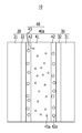
도 1은 일 구현예에 따른 리튬 이차 전지의 개략적인 구성을 나타내는 단면도이다.
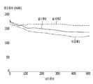
도 2는 실시예 1 및 2와 비교예 1에 따른 리튬 이차 전지의 사이클 수와 방전 용량과의 관계를 나타내는 그래프이다.
도 3은 리튬 화합물의 첨가량과 리튬 이차 전지의 방전 용량과의 관계를 나타내는 그래프이다.
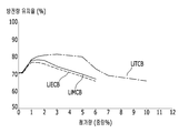
도 4는 리튬 화합물의 첨가량과 리튬 이차 전지의 방전 용량 유지율과의 관계를 나타내는 그래프이다.
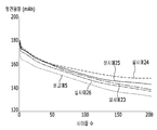
도 5는 실시예 23 내지 26 및 비교예 5에 따른 리튬 이차 전지의 사이클 수와 방전 용량과의 관계를 나타내는 그래프이다.
도 6은 실시예 27 내지 29 및 비교예 6에 따른 리튬 이차 전지의 사이클 수와 방전 용량과의 관계를 나타내는 그래프이다.1 is a cross-sectional view showing a schematic configuration of a lithium secondary battery according to one embodiment.
Fig. 2 is a graph showing the relationship between the number of cycles and the discharge capacity of the lithium secondary battery according to Examples 1 and 2 and Comparative Example 1. Fig.
3 is a graph showing the relationship between the amount of lithium compound added and the discharge capacity of a lithium secondary battery.
4 is a graph showing the relationship between the addition amount of the lithium compound and the discharge capacity retention rate of the lithium secondary battery.
5 is a graph showing the relationship between the number of cycles and the discharge capacity of the lithium secondary battery according to Examples 23 to 26 and Comparative Example 5. Fig.
6 is a graph showing the relationship between the number of cycles and the discharge capacity of the lithium secondary battery according to Examples 27 to 29 and Comparative Example 6. Fig.
이하, 본 발명의 구현예를 상세히 설명하기로 한다. 다만, 이는 예시로서 제시되는 것으로, 이에 의해 본 발명이 제한되지는 않으며 본 발명은 후술할 청구범위의 범주에 의해 정의될 뿐이다. Hereinafter, embodiments of the present invention will be described in detail. However, it should be understood that the present invention is not limited thereto, and the present invention is only defined by the scope of the following claims.
본 명세서에서 특별한 언급이 없는 한, "치환"이란 화합물 중의 적어도 하나의 수소 원자가 할로겐 원자(F, Cl, Br, I), 히드록시기, C1 내지 C20의 알콕시기, 니트로기, 시아노기, 아민기, 이미노기, 아지도기, 아미디노기, 히드라지노기, 히드라조노기, 카르보닐기, 카르바밀기, 티올기, 에스테르기, 에테르기, 카르복실기 또는 그것의 염, 술폰기 또는 그것의 염, 인산이나 그것의 염, C1 내지 C20의 알킬기, C2 내지 C20의 알케닐기, C2 내지 C20의 알키닐기, C6 내지 C30의 아릴기, C3 내지 C20의 사이클로알킬기, C3 내지 C20의 사이클로알케닐기, C3 내지 C20의 사이클로알키닐기, C2 내지 C20의 헤테로사이클로알킬기, C2 내지 C20의 헤테로사이클로알케닐기, C2 내지 C20의 헤테로사이클로알키닐기 또는 이들의 조합의 치환기로 치환된 것을 의미한다.Unless otherwise specified herein, "substituted" means that at least one hydrogen atom in the compound is replaced by a halogen atom (F, Cl, Br, I), a hydroxy group, a C1- A thio group, an ester group, an ether group, a carboxyl group or a salt thereof, a sulfone group or a salt thereof, a phosphoric acid or a salt thereof, an amide group, an imino group, an azido group, an amidino group, a hydrazino group, a hydrazino group, a carbonyl group, a carbamoyl group,
일 구현예에 따른 리튬 이차 전지는 도 1을 참고하여 설명한다.A lithium secondary battery according to one embodiment will be described with reference to Fig.
도 1은 일 구현예에 따른 리튬 이차 전지의 개략적인 구성을 나타내는 단면도이다.1 is a cross-sectional view showing a schematic configuration of a lithium secondary battery according to one embodiment.
도 1을 참고하면, 리튬 이차 전지(10)는 양극(20), 음극(30), 그리고 세퍼레이터층(40)을 포함한다. 상기 세퍼레이터층(40)은 세퍼레이터(40a) 및 전해액(43)을 포함한다. 상기 양극(20)은 집전체(21) 및 양극 활물질층(22)을 포함하며, 상기 세퍼레이터(40a)는 기재(41) 및 상기 기재(41)의 적어도 일면에 위치하는 다공질층(42)을 포함한다.Referring to FIG. 1, a lithium
일 구현예에서는, 상기 양극 활물질층(22)과 상기 다공질층(42) 중 적어도 하나는 보호막 형성 물질을 포함할 수 있다. 상기 보호막 형성 물질은 후술하는 양극 활물질층(22)과 다공질층(42) 부분에서 자세히 설명한다.In one embodiment, at least one of the cathode
상기 리튬 이차 전지(10)의 충전 도달 전압(산화 환원 전위)은 예를 들면, 4.3V 이상 5.0V 이하(vs.Li/Li+)가 될 수 있고, 구체적으로는 4.5V 이상 5.0V 이하가 될 수 있다.The voltage of the
상기 리튬 이차 전지(10)의 형태는 특별히 한정되지 않는다. 다시 말해, 리튬 이차 전지(10)는 원통형, 각형, 라미네이트형, 버튼형 등의 어떠한 형태도 가능하다.The shape of the lithium
상기 양극(20)은 집전체(21) 및 양극 활물질층(22)을 포함한다.The anode (20) includes a current collector (21) and a cathode active material layer (22).
상기 집전체(21)는 도전체라면 어떤 것이든 가능하며, 예를 들면, 알루미늄, 스테인리스강, 니켈 도금 강철 등을 들 수 있다. The
상기 양극 활물질층(22)은 양극 활물질을 포함하고, 도전재 및 결착제를 추가로 포함할 수 있다.The cathode
상기 양극 활물질은 예를 들면, 리튬을 포함하는 고용체 산화물일 수 있으나, 전기 화학적으로 리튬 이온을 흡장 및 방출할 수 있는 물질이라면 특별히 제한되지 않는다. The cathode active material may be, for example, a solid solution oxide containing lithium, but is not particularly limited as long as it is a material capable of occluding and releasing lithium ions electrochemically.
상기 고용체 산화물은 예를 들면, 하기 화학식 1 내지 3으로 표시되는 화합물 중 적어도 하나일 수 있다.The solid solution oxide may be, for example, at least one of the compounds represented by the following general formulas (1) to (3).
[화학식 1][Chemical Formula 1]
LiaMnxCoyNizO2 Li a Mn x Co y Ni z O 2
(상기 화학식 1에서, 1.150≤a≤1.430, 0.45≤x≤0.6, 0.10≤y≤0.15, 0.20≤z≤0.28 이다.) (In the
[화학식 2](2)
LiMnxCoyNizO2 LiMn x Co y Ni z O 2
(상기 화학식 2에서, 0.3≤x≤0.85, 0.10≤y≤0.3, 0.10≤z≤0.3 이다.)(In the
[화학식 3](3)
LiMn1 .5Ni0 .5O4 LiMn 1 .5 Ni 0 .5 O 4
상기 양극 활물질의 함유량은 상기 양극 활물질층의 총량에 대하여 85 내지 96 중량%일 수 있고, 구체적으로는 88 내지 94 중량%일 수 있다. 상기 양극 활물질의 함유량이 상기 범위 내일 경우 사이클 수명 특성 및 양극의 에너지 밀도가 향상될 수 있다. 예를 들면, 상기 양극의 에너지 밀도는 530 Wh/l(180 Wh/kg) 이상으로 증가시킬 수 있다.The content of the cathode active material may be 85 to 96% by weight, and more preferably 88 to 94% by weight based on the total amount of the cathode active material layer. When the content of the cathode active material is within the above range, the cycle life characteristics and the energy density of the anode can be improved. For example, the energy density of the anode can be increased to 530 Wh / l (180 Wh / kg) or more.
일 구현예에 따르면, 상기 양극 활물질층(22)은 상기 보호막 형성 물질을 포함할 수 있다.According to one embodiment, the cathode
상기 보호막 형성 물질은 리튬 이차 전지의 충전시, 구체적으로는 첫 사이클 충전시, 보호막을 형성할 수 있는 물질이다. 상기 보호막은 상기 전해액(43) 내의 리튬 이온을 통과시키는 동시에 용매의 통과를 억제시킬 수 있다. 상기 보호막 형성 물질, 즉, 보호막 형성 물질을 첨가할 경우 높은 전류밀도 및 고전압 하에서 사이클 수명 특성이 향상될 수 있다.The protective film forming material is a material capable of forming a protective film upon charging the lithium secondary battery, specifically, charging the first cycle. The protective film may pass lithium ions in the
상기 보호막 형성 물질은 리튬 이온, 음이온화 중심 원자, 그리고 상기 중심 원자에 배위된 시아노기를 포함하는 리튬 화합물일 수 있다. 다시 말하면, 상기 보호막 형성 물질은 리튬 이온과, 시아노기를 포함하는 음이온 착체와의 리튬 염일 수 있다.The protective film forming material may be a lithium compound including a lithium ion, an anionized central atom, and a cyano group coordinated to the central atom. In other words, the protective film forming material may be a lithium salt of lithium ion and an anion complex including a cyano group.
상기 중심 원자는 붕소, 인 및 탄소로부터 선택될 수 있다.The central atom may be selected from boron, phosphorus, and carbon.
상기 보호막 형성 물질은 구체적으로 하기 화학식 4 내지 6으로 표시되는 리튬 화합물 중 적어도 하나일 수 있다.The protective film forming material may be at least one of the lithium compounds represented by the following formulas (4) to (6).
[화학식 4][Chemical Formula 4]
LiB(CN)4- n1(X1)n1 LiB (CN) 4- n1 (X 1) n1
[화학식 5][Chemical Formula 5]
LiP(CN)6- n2(X2)n2 LiP (CN) 6- n2 (X 2) n2
[화학식 6][Chemical Formula 6]
LiC(CN)3- n3(X3)n3 LiC (CN) 3- n3 (X 3) n3
(상기 화학식 4 내지 6에서, (In the
n1은 0 내지 3의 정수이고, n 1 is an integer of 0 to 3,
n2는 0 내지 5의 정수이고, n 2 is an integer of 0 to 5,
n3은 0 내지 2의 정수이고, n 3 is an integer of 0 to 2,
X1 내지 X3은 시아노기 이외의 리간드이고, 예를 들면, 예를 들면, 할로겐 원자, 치환 또는 비치환된 C1 내지 C10 알콕시기, 치환 또는 비치환된 C1 내지 C4의 플루오로알킬기, 쇄상 또는 환형 카르복시기, 술포닐기 등을 들 수 있다.)X 1 to X 3 are ligands other than a cyano group and include, for example, a halogen atom, a substituted or unsubstituted C1 to C10 alkoxy group, a substituted or unsubstituted C1 to C4 fluoroalkyl group, A cyclic carboxy group, a sulfonyl group, etc.).
상기 양극 활물질은 결정 구조를 가짐에 따라 복수 개의 활성점을 가진다. 그리고, 충전시 각 활성점의 근방에 존재하는 상기 보호막 형성 물질은 시아노기의 질소 원자가 갖고 있는 고립 전자대로부터 전자를 상기 활성점에 공급한다. 이에 따라 시아노기의 질소 원자가 양이온 라디칼이 되어 상기 보호막 형성 물질은 분해하게 된다.The cathode active material has a plurality of active points as having a crystal structure. The protective film forming material present in the vicinity of each active point at the time of charging supplies electrons from the isolated electrons possessed by the nitrogen atom of the cyano group to the active point. As a result, the nitrogen atom of the cyano group becomes a cation radical, and the protective film forming material is decomposed.
또한 시아노기의 삼중 결합을 구성하는 전자의 하나가 상기 활성점에 공급될 수도 있다. 그리고 양이온 라디칼은 이에 인접하는 것 외에 다른 보호막 형성 물질 중의 시아노기에 붙을 수 있다. 구체적으로, 양이온 라디칼은 시아노기의 고립 전자대를 공격하여 상기 시아노기에 붙을 수 있다. 이에 따라 보호막 형성 물질끼리 중합할 수 있다.One of the electrons constituting the triple bond of the cyano group may also be supplied to the active site. And the cation radical may be attached to a cyano group in a protective film forming material other than the adjoining cation radical. Specifically, the cation radical can attack the isolated electron band of the cyano group and attach to the cyano group. Thus, the protective film forming materials can be polymerized with each other.
또한 양이온 라디칼은 시아노기의 삼중 결합 부분을 공격할 수도 있다. 다른 보호막 형성 물질이 복수 개의 시아노기를 가질 경우, 자유 시아노기 중의 질소 원자가 새로운 양이온 라디칼이 될 수 있다. 이후, 동일한 중합 반응이 반복됨으로써 활성점 위로 보호막 형성 물질의 중합체, 즉, 보호막이 형성될 수 있다. The cation radical may also attack the triple bond portion of the cyano group. When another protecting film forming material has a plurality of cyano groups, the nitrogen atom in the free cyano group may be a new cation radical. Thereafter, by repeating the same polymerization reaction, a polymer of the protective film forming material, that is, a protective film can be formed on the active point.
상기 보호막 형성 물질의 분해 및 중합은 상기 전해액의 용매의 분해보다 낮은 전위에서 일어난다. 다시 말하면, 보호막 형성 물질의 분해 및 중합은 용매의 분해보다 먼저 일어날 수 있다. 이와 같이 형성된 보호막은 용매의 통과를 억제할 수 있다.The decomposition and polymerization of the protective film-forming material occurs at a lower potential than the decomposition of the solvent of the electrolyte solution. In other words, the decomposition and polymerization of the protective film-forming material may occur before the decomposition of the solvent. The protective film thus formed can suppress the passage of the solvent.
상기 보호막은 음이온 착체를 포함하므로, 리튬 이온은 음이온 착체의 중심 원자 사이를 끼어듦으로써 상기 보호막을 통과할 수 있다. Since the protective film includes an anionic complex, lithium ions can pass through the protective film by interposing the center atoms of the anionic complex.
따라서 상기 보호막은 상기 전해액 내의 리튬 이온을 통과시키는 동시에 용매의 통과를 억제할 수 있다. 다시 말하면, 상기 보호막은 2회 사이클 이후의 충전시, 활성점과 리튬 이온과의 반응을 촉진하면서, 활성점과 용매와의 반응, 즉, 용매의 분해를 억제할 수 있다. 이에 따라 사이클 수명 특성이 향상될 수 있다.Therefore, the protective film can pass lithium ions in the electrolytic solution and inhibit the passage of solvent. In other words, the protective film can suppress the reaction between the active site and the solvent, that is, the decomposition of the solvent, while promoting the reaction between the active site and the lithium ion upon charging after two cycles. Thus, cycle life characteristics can be improved.
상기 보호막 형성 물질 중의 시아노기의 수가 많을수록 복잡한 구조를 가지는 동시에 안정된 구조의 보호막을 형성할 수 있고, 상기 보호막 형성 물질은 용매에 용해가 어려우므로 음극 상에서 분해할 가능성이 줄어든다. As the number of cyano groups in the protective film forming material increases, the protective film having a complicated structure and having a stable structure can be formed, and the protective film forming material is difficult to dissolve in a solvent, thereby reducing the possibility of decomposition on the negative electrode.
이에 따라 구체적으로는, 상기 화학식 4 내지 6에서 n1 및 n3은 0일 수 있고, n2는 입체 구조상의 관점에서 3일 수 있다. 인 원소를 중심 원자로 한 착체는 정팔면체의 구조를 가지므로, 시아노기가 3개일 경우 입체 구조상 가장 안정할 수 있다. 또한 n1 내지 n3이 상기 수치를 가질 경우, 시아노기는 중심 원자 사이를 끼어듦으로써 서로 대조되는 위치에 배치되므로 보호막이 안정화될 수 있다.Accordingly, in the
상기 보호막 형성 물질의 첨가량은 상기 양극 활물질층의 총량에 대하여 0.1 내지 6 중량%로 포함될 수 있고, 구체적으로는 상기 보호막 형성 물질의 조성마다 다를 수 있다. 상기 보호막 형성 물질의 첨가량이 상기 범위 내일 경우 전해액에의 용출이 억제되고 보호막의 두께가 적당하여 용매의 통과를 억제하면서 리튬 이온을 통과시킬 수 있다.The amount of the protective film forming material to be added may be 0.1 to 6% by weight based on the total amount of the positive active material layer, and may vary depending on the composition of the protective film forming material. When the added amount of the protective film forming material is within the above range, elution into the electrolytic solution is inhibited and the thickness of the protective film is appropriate, so that lithium ions can be passed while suppressing the passage of the solvent.
구체적으로, 상기 보호막 형성 물질이 상기 화학식 4로 표시되는 리튬 화합물인 경우, 상기 보호막 형성 물질은 상기 양극 활물질층의 총량에 대하여 0.5 내지 6 중량%로 포함될 수 있고, 구체적으로는 0.5 내지 4 중량%로 포함될 수 있다. 구체적으로, 시아노기가 많아질수록 상기 화학식 1로 표시되는 리튬 화합물의 첨가량은 많아질 수 있다. 시아노기가 많을수록 다량의 보호막 형성 물질을 상기 양극 활물질층에 첨가하더라도 보호막 형성 물질의 전해액에의 용해량을 낮출 수 있다. Specifically, when the protective film forming material is a lithium compound represented by the
구체적으로, 상기 화학식 4로 표시되는 리튬 화합물의 함량의 상한을 나타내는 w1은 n1이 0인 경우 6이 되고 n1이 클수록 작아질 수 있다. 구체적으로, n1이 1인 경우 w1은 4가 되고, n1이 2인 경우 w1은 3이 되고, n1이 3인 경우 w1은 2가 될 수 있다. 이와 같이, 시아노기의 수가 많을수록 상기 보호막 형성 물질의 첨가량이 많아질 수 있다. 시아노기의 수가 많을수록 다량의 보호막 형성 물질을 상기 양극 활물질층에 첨가하더라도 보호막 형성 물질의 전해액에의 용해량을 낮출 수 있다. Specifically, w 1, which represents the upper limit of the content of the lithium compound represented by the formula (4), becomes 6 when n 1 is 0, and can be smaller when n 1 is larger. Specifically, when n 1 is 1,
구체적으로, n1이 0인 경우 상기 보호막 형성 물질은 1 중량% 이상 5 중량% 이하로 포함될 수 있고, 구체적으로는 1.5 중량% 이상 4 중량% 이하로 포함될 수 있다. 또한 n1이 1인 경우 상기 보호막 형성 물질은 0.7 중량% 이상 2 중량% 이하로 포함될 수 있다. 상기 보호막 형성 물질이 상기 범위 내로 포함될 경우 사이클 수명 특성이 향상될 수 있다. Specifically, when n 1 is 0, the protective film forming material may be contained in an amount of 1 wt% or more and 5 wt% or less, specifically, 1.5 wt% or more and 4 wt% or less. When n 1 is 1, the protective film forming material may be contained in an amount of 0.7 wt% or more and 2 wt% or less. When the protective film forming material is included in the above range, the cycle life characteristics can be improved.
상기 보호막 형성 물질이 상기 화학식 5로 표시되는 리튬 화합물인 경우, 상기 보호막 형성 물질은 상기 양극 활물질층의 총량에 대하여 0.3 내지 2 중량%로 포함될 수 있다. 상기 화학식 5로 표시되는 리튬 화합물의 함량의 상한을 나타내는 w2는 n2가 3 일때 3이 되고 │3-n2│의 값이 클수록 작아질 수 있다. 구체적으로, │3-n2│의 값이 1인 경우 w2는 2가 되고, │3-n2│의 값이 2인 경우 w2는 1.5가 되고, │3-n2│의 값이 3인 경우 w2는 1.0이 될 수 있다. 상기 보호막 형성 물질의 첨가량은 n2가 3 일때 가장 클 수 있다. 상기 보호막 형성 물질은 시아노기의 수가 세 개일 때 입체 구조상 가장 안정될 수 있다. When the protective film forming material is a lithium compound represented by the
상기 보호막 형성 물질이 상기 화학식 6으로 표시되는 리튬 화합물인 경우, 상기 보호막 형성 물질은 상기 양극 활물질층의 총량에 대하여 0.5 내지 3 중량%로 포함될 수 있다. 상기 화학식 6으로 표시되는 리튬 화합물의 함량의 상한을 나타내는 w3은 n3이 0 일때 3이 되고 n3의 값이 클수록 작아질 수 있다. 구체적으로, n3이 1인 경우 w3은 2가 되고, n3이 2인 경우 w3은 1이 될 수 있다. When the protective film forming material is a lithium compound represented by
이와 같이 시아노기의 수가 많을수록 상기 보호막 형성 물질의 첨가량은 많아질 수 있다. 시아노기의 수가 많을수록 다량의 보호막 형성 물질을 양극 활물질층 내에 첨가하더라도, 보호막 형성 물질의 전해액에의 용해량을 낮출 수 있다.The greater the number of cyano groups, the greater the amount of the protective film forming material added. As the number of cyano groups increases, the amount of the protective film forming material dissolved in the electrolyte can be reduced even if a large amount of the protective film forming material is added to the cathode active material layer.
상기 도전재는 예를 들면, 케첸 블랙(KETJEN BLACK), 아세틸렌 블랙 등의 카본블랙; 천연흑연, 인조흑연 등의 흑연을 들 수 있으나, 양극의 도전성을 높이기 위한 것이라면 특별히 제한되지 않는다. The conductive material may be, for example, carbon black such as KETJEN BLACK, acetylene black or the like; Graphite such as natural graphite and artificial graphite. However, it is not particularly limited as long as it is for increasing the conductivity of the anode.
상기 도전재의 함유량은 상기 양극 활물질층의 총량에 대하여 3 내지 10 중량%로 포함될 수 있고, 구체적으로는 4 내지 6 중량%로 포함될 수 있다. 상기 도전재가 상기 범위 내로 포함되는 경우 사이클 수명 특성 및 에너지 밀도가 향상될 수 있다.The conductive material may be contained in an amount of 3 to 10% by weight, and more preferably 4 to 6% by weight based on the total weight of the cathode active material layer. When the conductive material is included within the above range, the cycle life characteristics and the energy density can be improved.
상기 결착제는 예를 들면, 폴리불화비닐리덴, 에틸렌-프로필렌-디엔 삼원 공중합체, 스티렌-부타디엔 고무, 아크릴로니트릴-부타디엔 고무, 플루오르 고무, 폴리아세트산비닐, 폴리메틸메타크릴레이트, 폴리에틸렌, 니트로셀룰로오스 등을 들 수 있으나, 양극 활물질 및 도전재를 상기 집전체(21) 위에 결착시킬 수 있는 것이라면, 특별히 제한되지 않는다. Examples of the binder include polyvinylidene fluoride, ethylene-propylene-diene terpolymer, styrene-butadiene rubber, acrylonitrile-butadiene rubber, fluor rubber, polyvinyl acetate, polymethyl methacrylate, polyethylene, Cellulose, and the like, but is not particularly limited as long as it can bind the positive electrode active material and the conductive material on the
상기 결착제의 함유량은 상기 양극 활물질층의 총량에 대하여 3 내지 7 중량%일 수 있고, 구체적으로는 4 내지 6 중량%일 수 있다. 결착제의 함유량이 상기 범위 내일 경우 사이클 수명 특성 및 에너지 밀도가 향상될 수 있다.The content of the binder may be 3 to 7% by weight, and more preferably 4 to 6% by weight based on the total weight of the cathode active material layer. When the content of the binder is within the above range, cycle life characteristics and energy density can be improved.
상기 양극 활물질층(22)의 밀도는 특별히 제한되지 않지만, 예를 들면, 2.0 내지 3.0 g/cm3 일 수 있고, 구체적으로는 2.5 내지 3.0 g/cm3 일 수 있다. 상기 양극 활물질층(22)의 밀도가 상기 범위 내일 경우 양극 활물질의 입자가 파괴되지 않으므로 입자 간의 전기적 접촉으로 인한 손상의 우려가 적으며 양극 활물질의 이용률이 높아짐에 따라 사이클 수명 특성 및 에너지 밀도가 향상될 수 있다.Although the density of the positive electrode
상기 양극 활물질층(22)의 밀도는 양극 활물질층(22)의 압연 후의 면밀도를 양극 활물질층(22)의 압연 후의 두께로 나눈 값으로 얻어질 수 있다.The density of the cathode
상기 양극 활물질층(22)은 예를 들면, 상기 양극 활물질, 상기 도전재 및 상기 결착제를 건식 혼합하여 혼합물을 얻은 후, 상기 혼합물과 상기 보호막 형성 물질을 건식 혼합하여 건식 혼합물을 얻는다. 이후 상기 건식 혼합물을 유기 용매에 분산시켜 슬러리를 형성하고, 상기 슬러리를 집전체(21) 위에 도포하고, 건조 및 압연하여 형성될 수 있다. 또는 상기 혼합물이 분산된 슬러리를 형성한 후, 상기 슬러리에 보호막 형성 물질을 용해할 수도 있다. 즉, 보호막 형성 물질을 양극 활물질층에 첨가하는 방법은 제한되지 않는다.The cathode
상기 유기 용매는 상기 보호막 형성 물질을 용해할 수 있는 종류를 사용할 수 있다. 이 경우 상기 양극 활물질층 내에 균일하게 분산시킬 수 있다. 이러한 유기 용매의 종류로는 예를 들면, N-메틸-2-피롤리돈 등을 들 수 있다.The organic solvent may be a solvent capable of dissolving the protective film forming material. In this case, it can be uniformly dispersed in the positive electrode active material layer. Examples of the organic solvent include N-methyl-2-pyrrolidone and the like.
도포의 방법은 특별히 한정되지 않으며, 예를 들면, 나이프 코터법, 그라비아 코터법 등을 들 수 있다. The coating method is not particularly limited, and examples thereof include a knife coater method and a gravure coater method.
상기 양극(20)은 프레스기에 의해 상기 양극 활물질층(22)을 프레스하고 진공 건조를 수행하여 제조할 수 있다.The
상기 양극 활물질층(22)을 상기 집전체(21) 위에 도포시 증점제로서 카르복시메틸셀룰로오스(CMC)를 상기 결착제 총량의 1/10 이상 중량 이하로 함께 사용할 수도 있다.Carboxymethylcellulose (CMC) as a thickener may be used in an amount of 1/10 or more by weight of the total amount of the binder when the positive electrode
상기 음극(30)은 집전체(31) 및 음극 활물질층(32)을 포함한다.The
상기 집전체(31)는 예를 들면, 알루미늄, 스테인리스강, 니켈 도금 강철 등이 사용되될 수 있다.As the
상기 음극 활물질층(32)은 리튬 이차 전지의 음극 활물질층으로서 사용되는 것이라면, 어떠한 것이든 사용 가능하다. 예를 들면, 음극 활물질층(32)은 음극 활물질을 포함하고, 결착제를 추가로 포함할 수 있다.The negative electrode
상기 음극 활물질은 전기 화학적으로 리튬 이온을 흡장 및 방출할 수 있는 물질이라면 특별히 제한되지 않는다. 예를 들면, 인조흑연, 천연흑연, 인조흑연과 천연흑연과의 혼합물, 인조흑연을 피복한 천연흑연, 규소, 규소 함유 합금, 규소 산화물, 주석, 주석 함유 합금, 주석 산화물, 규소 산화물과 흑연 물질의 혼합물, 주석 산화물과 흑연 물질의 혼합물, Li4Ti5O12 등의 산화 티탄계 화합물 등을 들 수 있다.The negative electrode active material is not particularly limited as long as it is a material capable of occluding and releasing lithium ions electrochemically. Natural graphite, natural graphite coated with artificial graphite, silicon, silicon-containing alloy, silicon oxide, tin, tin-containing alloy, tin oxide, silicon oxide and graphite material A mixture of tin oxide and graphite material, a mixture of Li 4 Ti 5 O 12 , And the like.
상기 규소 산화물은 SiOx(0≤x≤2)로 표시될 수 있다.The silicon oxide may be represented by SiOx (0? X? 2).
상기 음극 활물질의 함유량은 상기 음극 활물질층의 총량에 대하여 90 내지 98 중량%일 수 있다. 상기 음극 활물질의 함유량이 상기 범위 내일 경우 사이클 수명 특성 및 에너지 밀도가 향상될 수 있다.The content of the negative electrode active material may be 90 to 98% by weight based on the total amount of the negative electrode active material layer. When the content of the negative electrode active material is within the above range, the cycle life characteristics and the energy density can be improved.
상기 결착제는 상기 양극 활물질층(22)을 구성하는 결착제와 동일한 것일 수 있다.The binder may be the same as the binder constituting the positive electrode
상기 증점제를 포함시킨 결착제의 함유량은 상기 음극 활물질층의 총량에 대하여 1 내지 10 중량% 일 수 있다. 상기 증점제를 포함시킨 결착제의 함유량이 상기 범위 내일 경우 사이클 수명 특성 및 에너지 밀도가 향상될 수 있다.The content of the binder containing the thickener may be 1 to 10% by weight based on the total weight of the anode active material layer. When the content of the binder containing the thickener is within the above range, the cycle life characteristics and the energy density can be improved.
상기 음극 활물질층(32)의 밀도는 특별히 제한되지 않지만, 예를 들면, 1.0 내지 2.0 g/cm3 일 수 있다. 상기 음극 활물질층(32)의 밀도가 상기 범위 내일 경우 사이클 수명 특성 및 에너지 밀도가 향상될 수 있다.The density of the negative electrode
상기 음극 활물질층(32)은 예를 들면, 음극 활물질 및 결착제를 용매, 예를 들면, N-메틸-2-피롤리돈 또는 물에 분산시켜 슬러리를 형성하고, 이 슬러리를 집전체(31) 위에 도포 및 건조하여 형성될 수 있다. 이어서, 프레스기에 의해 음극 활물질층(32)을 프레스하여, 음극(30)을 제조할 수 있다.The anode
상기 음극 활물질층(32)의 밀도는 상기 음극 활물질층(32)의 압연 후의 면밀도를 상기 음극 활물질층(32)의 압연 후의 두께로 나눈 값으로 얻어질 수 있다.The density of the negative electrode
상기 세퍼레이터(40a)는 기재(41) 및 상기 기재(41)의 적어도 일면에 위치하는 다공질층(42)을 포함한다.The
상기 기재(41)는 폴리에틸렌, 폴리프로필렌 등의 재료로 이루어지고, 다수의 제1 기공(41a)을 포함할 수 있다.The
도 1에서는 상기 제1 기공(41a)이 구형이지만, 이에 한정되지 않고 여러 형상을 가질 수 있다. Although the
상기 제1 기공(41a)의 구경은 예를 들면, 0.1 내지 0.5 ㎛ 일 수 있다. 상기 제1 기공(41a)의 구경은 예를 들면, 상기 제1 기공(41a)을 구형으로 간주했을 때의 직경을 의미한다.The diameter of the
상기 제1 기공(41a)은 예를 들면, 자동 porosimeterAutoporeIV(시마즈 제작소 주식회사(Shimadzu Corporation))에 의해 측정될 수 있다. 상기 측정 장치는 예를 들면, 상기 제1 기공(41a)의 구경 분포를 측정하고, 분포가 가장 높은 구경을 대표 값으로 측정할 수 있다.The
상기 기재(41)의 표면층에 존재하는 상기 제1 기공(41a)의 구경은 예를 들면, 주사전자 현미경(JSM-6060 니혼전자 주식 회사(JEOL Ltd.))에 의해 측정할 수도 있다. 상기 측정 장치는 예를 들면, 표면층에 있어서의 상기 제1 기공(41a) 각각에 대해서 구경을 측정할 수 있다.The diameter of the
상기 기재(41)의 기공율은 예를 들면, 38 내지 44 부피% 일 수 있다. 상기 기재(41)의 기공율이 상기 범위 내일 경우 사이클 수명 특성이 향상될 수 있다. 상기 기재(41)의 기공율은 상기 제1 기공(41a)의 총 부피를 상기 기재(41)의 총 부피로 나눈 값으로 얻어질 수 있다. 상기 기재(41)의 기공율은 예를 들면, 자동 porosimeter AutoporeIV(시마즈 제작소 주식 회사)에 의해 측정될 수 있다.The porosity of the
상기 기재(41)의 두께는 6 내지 19 ㎛ 일 수 있다. 상기 기재(41)의 두께가 상기 범위 내일 경우 사이클 수명 특성이 향상될 수 있다.The thickness of the
상기 다공질층(42)은 상기 기재(41)와 다른 재료, 예를 들면, 폴리불화비닐리덴, 폴리아미드이미드, 아라미드(방향족 폴리아미드) 등의 재료로 이루어질 수 있고, 다수의 제2 기공(42a)을 포함할 수 있다.The
도 1에서는 상기 제2 기공(42a)이 구형이지만, 여러 형상을 가질 수 있다.In FIG. 1, the
상기 제2 기공(42a)은 상기 제1 기공(41a)과 상이할 수 있다. The
구체적으로, 상기 제2 기공(42a)의 구경 및 기공율이 상기 제1 기공(41a)의 값보다 클 수 있다. 다시 말해, 상기 제2 기공(42a)의 구경은 예를 들면, 1 내지 2 ㎛ 일 수 있다.Specifically, the diameter and the porosity of the
상기 제2 기공(42a)의 구경은 예를 들면, 상기 제2 기공(42a)을 구형으로 간주했을 때의 직경, 즉, 구상당 직경이며, 예를 들면, 주사전자 현미경(JSM-6060 니혼전자 주식 회사)에 의해 측정될 수 있다. The diameter of the
상기 다공질층(42)에 사용되는 폴리불화비닐리덴의 예로는, KUREHA CORPORATION제 KF폴리머#1700, #9200, #9300 등을 들 수 있다.Examples of the polyvinylidene fluoride used for the
상기 폴리불화비닐리덴의 중량평균분자량은 약 50만 내지 100만 일 수 있다.The weight average molecular weight of the polyvinylidene fluoride may be about 500,000 to 1,000,000.
상기 세퍼레이터(40a)의 기공율은 예를 들면, 39 내지 58 부피% 일 수 있다. 상기 세퍼레이터(40a)의 기공율이 상기 범위 내일 경우 사이클 수명 특성이 향상될 수 있다.The porosity of the
여기에서, 상기 세퍼레이터(40a)의 기공율은 상기 제1 기공(41a) 및 상기 제2 기공(42a)의 총 부피를, 상기 세퍼레이터(40a)의 총 부피(기재(41)의 수지 부분, 제1 기공(41a), 다공질층(42)의 수지 부분 및 제2 기공(42a)의 총 부피)로 나눈 값으로 얻어질 수 있다.The porosity of the
상기 세퍼레이터(40a)의 기공율은 예를 들면, 자동 porosimeter AutoporeIV(시마즈제작소 주식 회사)에 의해 측정될 수 있다.The porosity of the
상기 세퍼레이터(40a)의 기공율이 상기 기재(41)의 기공율 보다 크므로, 상기 다공질층(42)의 기공율, 다시 말해, 상기 제2 기공(42a)의 기공율은 상기 기재(41)의 기공율, 다시 말해, 상기 제1 기공(41a)의 기공율보다 높을 수 있다.The porosity of the
상기 다공질층(42)의 두께는 1 내지 5 ㎛ 일 수 있다. 또한 상기 세퍼레이터(40a)의 총 두께, 즉, 상기 기재(41)의 두께와 상기 다공질층(42)의 두께의 총합은 10 내지 25 ㎛ 일 수 있다. 상기 다공질층(42) 및 상기 세퍼레이터(40a)의 두께가 각각 상기 범위 내일 경우 사이클 수명 특성이 향상될 수 있다.The thickness of the
도 1에서 다공질층(42)은 기재(41)의 양면, 즉 양극(20)과 대면하고 음극(30)과 대면하여 기재의 양면에 위치하지만, 이에 한정되지 않는다. 구체적으로, 적어도 음극(30)과 대면하는 기재의 일면에 위치할 수 있다. 리튬 이차 전지의 사이클 수명 특성을 더욱 향상시키는 면에서는 다공질층(42)은 기재(41)의 양면에 형성될 수 있다.1, the
상기 기재(41)의 공기투과도(JIS P8117로 정의되는 공기투과도)는 특별히 제한되지 않지만, 예를 들면, 250 내지 300 sec/100cc 일 수 있다. 또한 상기 세퍼레이터(40a)의 공기투과도는 특별히 제한되지 않지만, 예를 들면, 220 내지 340 sec/100cc 일 수 있다. 상기 기재(41) 및 상기 세퍼레이터(40a)의 공기투과도가 각각 상기 범위 내일 경우 사이클 수명 특성이 향상될 수 있다.The air permeability (air permeability defined by JIS P8117) of the
상기 기재(41) 및 상기 세퍼레이터(40a)의 공기투과도는 예를 들면, 걸리(Gurley)식 공기투과도계(G-B2토요세이키 주식 회사(Toyobesq co., ltd.))에 의해 측정될 수 있다.The air permeability of the
상기 세퍼레이터(40a)는 다음과 같이 제조될 수 있다.The
다공질층(42)을 구성하는 수지와 수용성 유기 용매를 5 내지 10 : 90 내지 95의 중량비로 혼합하여 도포액을 제조한다. 상기 수용성 유기 용매로는 예를 들면, N-메틸-2-피롤리돈, 디메틸 아세트아미도(DMAc), 트리프로필렌글리콜(TPG) 등을 들 수 있다.The resin constituting the
이어서, 상기 도포액을 기재(41)의 양면 또는 한쪽 면에 1 내지 5 ㎛의 두께로 도포한다. 이어서, 도포액이 도포된 기재(41)를 응고액으로 처리하여 도포액 중의 수지를 응고시킨다. 이때 도포액이 도포된 기재(41)를 응고액으로 처리하는 방법으로는 예를 들면, 도포액이 도포된 기재(41)를 응고액에 함침시키는 방법, 도포액이 도포된 기재(41)에 응고액을 세차게 부는 방법 등을 들 수 있다. 이에 따라, 세퍼레이터(40a)를 제조할 수 있다.Subsequently, the coating liquid is applied on both sides or one side of the
상기 응고액은 예를 들면, 상기의 수용성 유기 용매에 물을 혼합시켜 얻을 수 있다.The coagulating solution can be obtained, for example, by mixing water with the water-soluble organic solvent.
물의 혼합량은 응고액의 총 부피에 대하여 40 내지 80 부피%로 사용될 수 있다.The mixing amount of water may be used in an amount of 40 to 80% by volume based on the total volume of the coagulating solution.
이어서, 세퍼레이터(40a)를 수세 및 건조하여 세퍼레이터(40a)로부터 물 및 수용성 유기 용매를 제거한다.Subsequently, the
다른 일 구현예에 따르면, 상기 다공질층(42)은 전술한 보호막 형성 물질을 포함할 수 있다.According to another embodiment, the
상기 보호막 형성 물질이 상기 다공질층에 첨가될 경우, 보호막은 상기 다공질층(42)과 상기 양극 활물질층(22) 사이의 계면에 형성될 수 있다. 구체적으로, 상기 보호막 형성 물질은 상기 양극(20)과 대면하는 상기 다공질층(42)에 첨가될 수 있다. 상기 다공질층 내에 분산된 상기 보호막 형성 물질 중 상기 양극 활물질층에 접촉하고 있는 물질은 충전시 분해 및 중합할 수 있고, 이에 따라 다공질층(42)과 양극 활물질층(22) 사이의 계면에 보호막을 형성할 수 있다. 다시 말하면, 상기 보호막 형성 물질은 양극 활물질과 전해액과의 계면에 보호막을 형성할 수 있다.When the protective film forming material is added to the porous layer, a protective film may be formed at the interface between the
상기 보호막은 상기 보호막 형성 물질이 중합되어 형성된 중합체일 수 있다.The protective film may be a polymer formed by polymerizing the protective film forming material.
또한 상기 보호막 형성 물질은 상기 음극과 대면하는 상기 다공질층(42)에도 첨가될 수 있다. The protective film forming material may also be added to the
상기 보호막 형성 물질은 상기 다공질층의 총량에 대하여 10 내지 90 중량%로 포함될 수 있고, 구체적으로는 40 내지 90 중량%로 포함될 수 있다. 상기 보호막 형성 물질이 상기 범위 내로 포함되는 경우 양극 활물질과의 접촉량을 증가시킬 수 있고, 다공질층의 기공율을 용이하게 조절할 수 있다.The protective film forming material may be included in an amount of 10 to 90% by weight, and more preferably 40 to 90% by weight based on the total weight of the porous layer. When the protective film forming material is contained within the above range, the amount of contact with the cathode active material can be increased, and the porosity of the porous layer can be easily controlled.
상기 세퍼레이터는 다공질층을 구성하는 수지, 상기 보호막 형성 물질 및 수용성 유기용매를 포함하는 도포액을 기재(41)에 도포한 후, 상기 수지의 응고 및 상기 수용성 유기용매의 제거를 실시함으로써 형성될 수 있다. 상기 수용성 유기용매는 상기 보호막 형성 물질을 용해할 수 있다.The separator may be formed by applying a coating liquid containing a resin constituting the porous layer, the protective film forming material and a water-soluble organic solvent to the
또 다른 일 구현예에 따르면, 상기 양극 활물질층(22)과 상기 다공질층(42)은 모두 전술한 보호막 형성 물질을 포함할 수 있다.According to another embodiment, both the positive electrode
상기 보호막 형성 물질은 전해액 또는 음극에 첨가될 경우 보호막을 형성하기 어려울 뿐만 아니라, 음극에 첨가될 경우 음극 위에서 분해되고 이에 따라 생성된 분해 생성물은 음극 상에서의 반응에 악영향을 끼칠 수 있다. When the protective film-forming material is added to an electrolyte or a cathode, it is difficult to form a protective film. When the protective film-forming material is added to a cathode, the protective film-forming material is decomposed on the cathode and the decomposition product thus formed may adversely affect the reaction on the cathode.
상기 전해액(43)은 리튬염, 용매 및 첨가제를 포함할 수 있다.The
상기 리튬염은 상기 전해액(43)의 전해질이 될 수 있다.The lithium salt may be an electrolyte of the electrolytic solution (43).
상기 리튬염으로는 LiPF6, LiClO4, LiBF4, LiAsF6, LiSbF6, LiSO3CF3, LiN(SO2CF3), LiN(SO2CF2CF3), LiC(SO2CF2CF3)3, LiC(SO2CF3)3, LiI, LiCl, LiF, LiPF5(SO2CF3), LiPF4(SO2CF3)2 등을 들 수 있다. 이들 중 좋게는 LiPF6, LiClO4, LiBF4, LiAsF6, LiSbF6 등을 사용할 수 있다. 이들 리튬염은 단독으로 용해될 수도 있고 2종 이상 용해될 수도 있다. To the lithium salt is LiPF 6, LiClO 4, LiBF 4 ,
상기 리튬염이 상기 전해액(43) 내에 용해될 경우 사이클 수명 특성이 향상될 수 있다.When the lithium salt is dissolved in the
상기 리튬염의 농도(전해액에 복수 종류의 리튬염이 용해되는 경우에는 리튬염의 농도의 총합)는 1.15 내지 1.5 mol/L 일 수 있고, 구체적으로는 1.3 내지 1.45 mol/L 일 수 있다. 상기 리튬염의 농도가 상기 범위 내일 경우 사이클 수명 특성이 향상될 수 있다.The concentration of the lithium salt (the sum of the concentrations of the lithium salt when the plural kinds of lithium salts are dissolved in the electrolytic solution) may be 1.15 to 1.5 mol / L, and more specifically 1.3 to 1.45 mol / L. When the concentration of the lithium salt is within the above range, the cycle life characteristics can be improved.
상기 용매는 적어도 일부의 수소 원자가 플루오린 원자로 치환된 플루오르화 에테르를 포함할 수 있다.The solvent may comprise a fluorinated ether in which at least some of the hydrogen atoms have been replaced with fluorine atoms.
상기 플루오르화 에테르는 에테르의 수소를 플루오린으로 치환한 것으로, 산화내성이 향상될 수 있다.The fluorinated ether is obtained by replacing hydrogen of an ether with fluorine, and oxidation resistance can be improved.
상기 플루오르화 에테르의 예로는, 양극 재료의 충전 전압 및 전류 밀도에 대한 내성 등을 고려하면, 2,2,2-트리플루오로에틸메틸에테르, 2,2,2-트리플루오로에틸디플루오로메틸에테르, 2,2,3,3,3-펜타플루오로프로필메틸에테르, 2,2,3,3,3-펜타플루오로프로필디플루오로메틸에테르, 2,2,3,3,3-펜타플루오로프로필-1,1,2,2-테트라플루오로에틸에테르, 1,1,2,2-테트라플루오로 에틸메틸에테르, 1,1,2,2-테트라플루오로에틸에틸에테르, 1,1,2,2-테트라플루오로에틸프로필에테르, 1,1,2,2-테트라플루오로에틸부틸에테르, 1,1,2,2-테트라플루오로에틸이소부틸에테르, 1,1,2,2-테트라플루오로 에틸이소펜틸에테르, 1,1,2,2-테트라플루오로에틸-2,2,2-트리플루오로 에틸에테르, 1,1,2,2-테트라플루오로에틸-2,2,3,3-테트라플루오로 프로필에테르, 헥사플루오로이소프로필메틸에테르, 1,1,3,3,3-펜타 플루오로-2-트리플루오로메틸프로필메틸에테르, 1,1,2,3,3,3-헥사플루오로 프로필메틸에테르, 1,1,2,3,3,3-헥사플루오로프로필에틸에테르, 2,2,3,4,4,4-헥사플루오로부틸디플루오로메틸에테르 등을 들 수 있다. 이들을 단독으로 사용할 수도 있고 2종 이상 혼합하여 사용할 수도 있다.Examples of the fluorinated ether include 2,2,2-trifluoroethyl methyl ether, 2,2,2-trifluoroethyl difluoro, and 2,2,2-trifluoroethyl methyl ether, Methyl ether, 2,2,3,3,3-pentafluoropropyl methyl ether, 2,2,3,3,3-pentafluoropropyl difluoromethyl ether, 2,2,3,3,3- Pentafluoropropyl-1,1,2,2-tetrafluoroethyl ether, 1,1,2,2-tetrafluoroethyl methyl ether, 1,1,2,2-tetrafluoroethyl ethyl ether, 1 , 1,2,2-tetrafluoroethyl propyl ether, 1,1,2,2-tetrafluoroethyl butyl ether, 1,1,2,2-tetrafluoroethyl isobutyl ether, 1,1,2 , 2-tetrafluoroethyl isopentyl ether, 1,1,2,2-tetrafluoroethyl-2,2,2-trifluoroethyl ether, 1,1,2,2-tetrafluoroethyl- , 2,3,3-tetrafluoropropyl ether, hexafluoroisopropyl methyl ether, 1,1,3,3 , 3-pentafluoro-2-trifluoromethylpropyl methyl ether, 1,1,2,3,3,3-hexafluoropropyl methyl ether, 1,1,2,3,3,3-hexafluoro Propyl ethyl ether, 2,2,3,4,4,4-hexafluorobutyl difluoromethyl ether, and the like. These may be used alone or in combination of two or more.
상기 플루오르화 에테르는 상기 용매의 총 부피에 대하여 10 내지 60 부피%로 포함될 수 있고, 구체적으로는 30 내지 50 부피%로 포함될 수 있다. 상기 플루오르화 에테르의 함량이 상기 범위 내일 경우 사이클 수명 특성이 더욱 개선될 수 있다. 상기 플루오르화 에테르는 상기 보호막 형성 물질의 용해도가 탄산 에틸렌계의 유기 용매에 비해 낮으므로, 보호막 형성 물질의 전해액에의 용출을 억제할 수 있다.The fluorinated ether may be contained in an amount of 10 to 60% by volume based on the total volume of the solvent, specifically, 30 to 50% by volume. When the content of the fluorinated ether is within the above range, the cycle life characteristics can be further improved. Since the solubility of the protective film forming material in the fluorinated ether is lower than that of the organic solvent based on ethylene carbonate, the elution of the protective film forming material into the electrolytic solution can be suppressed.
상기 용매는 모노플루오로탄산 에틸렌을 더욱 포함할 수 있다.The solvent may further comprise ethylene monofluorocarbonate.
상기 모노플루오로탄산 에틸렌은 상기 용매의 총 부피에 대하여 10 내지 30 부피%로 포함될 수 있고, 구체적으로는 15 내지 20 부피%로 포함될 수 있다. 상기 모노플루오로탄산 에틸렌의 함량이 상기 범위 내일 경우 사이클 수명 특성이 더욱 향상될 수 있다. The monofluorocarbonic acid may be contained in an amount of 10 to 30% by volume based on the total volume of the solvent, and specifically 15 to 20% by volume. When the content of ethylene monofluorocarbonate is within the above range, the cycle life characteristics can be further improved.
상기 용매는 리튬 이차 전지에 사용되는 비수 용매를 더욱 포함할 수 있다.The solvent may further include a non-aqueous solvent used in a lithium secondary battery.
상기 첨가제는 음극 작용 화합물, 양극 작용 화합물, 에스테르계 화합물, 탄산 에스테르계 화합물, 황산 에스테르계 화합물, 인산 에스테르계 화합물, 붕산 에스테르계 화합물, 산무수물계 화합물, 전해질계 화합물 등을 들 수 있다. 이들을 단독으로 사용하거나 둘 이상을 혼합하여 사용할 수도 있다.Examples of the additive include an anode active compound, an anode active compound, an ester compound, a carbonate ester compound, a sulfate ester compound, a phosphate ester compound, a borate ester compound, an acid anhydride compound and an electrolyte compound. These may be used alone or in combination of two or more.
상기 음극 작용 화합물로는, 예를 들면, 센트럴유리제의 WCA-1, WCA-2, WCA-3 등을 들 수 있다.Examples of the negative-working compound include WCA-1, WCA-2 and WCA-3 of central glass.
상기 양극 작용 화합물로는, 예를 들면, 비스플루오로술포닐이미드 리튬(LiFSI) 등을 들 수 있다.Examples of the positive electrode active compound include bisfluorosulfonylimide lithium (LiFSI) and the like.
상기 에스테르계 화합물로는 디플루오로아세트산 메틸, 트리플루오로아세트산 디에틸, 아세트산 비닐, 아세트산 디플루오로에틸 등을 들 수 있다.Examples of the ester compounds include methyl difluoroacetate, diethyl trifluoroacetate, vinyl acetate, and difluoroethyl acetate.
상기 탄산 에스테르계 화합물로는 비닐렌 카보네이트, 비닐에틸렌 카보네이트, 디플루오로에틸렌 카보네이트, 디알릴 카보네이트, 2,5-디옥사헥산디메틸산 등을 들 수 있다.Examples of the carbonic ester compounds include vinylene carbonate, vinylethylene carbonate, difluoroethylene carbonate, diallyl carbonate, and 2,5-dioxahexanedimethanoic acid.
상기 황산 에스테르계 화합물로는 아황산 에틸렌, 아황산 디메틸, 황산 디메틸, 황산 에틸렌, 3-술포렌, 1,3-프로판 술톤, 1,4-부탄 술톤, 프로펜 술톤 등을 들 수 있다. Examples of the sulfuric ester compounds include ethylene sulfite, dimethyl sulfite, dimethyl sulfate, ethylene sulfate, 3-sulfolene, 1,3-propane sultone, 1,4-butane sultone and propene sultone.
상기 인산 에스테르계 화합물로는 트리메틸 인산, 트리옥틸 인산, 트리메틸실릴 인산, 트리메틸실릴 포스파인 등을 들 수 있다. Examples of the phosphoric acid ester compound include trimethylphosphoric acid, trioctylphosphoric acid, trimethylsilylphosphoric acid, and trimethylsilylphosphine.
상기 붕산 에스테르계 화합물로는 트리메틸 붕산, 트리메틸실릴 붕산 등을 들 수 있다.Examples of the boric acid ester-based compound include trimethylboric acid and trimethylsilylboric acid.
상기 산무수물계 화합물로는 숙신산 무수물, 알릴 숙신산 무수물, 에탄디술폰산 무수물 등을 들 수 있다.Examples of the acid anhydride-based compound include succinic anhydride, allylsuccinic anhydride, and ethane disulfonic anhydride.
상기 전해질계 화합물로는 비스(옥살레이토-O,O')붕산 리튬, 디플루오로(옥살레이토-O,O')붕산 리튬, 리튬 디플루오로비스(옥살레이토-O,O')인산 리튬 등을 들 수 있다.Examples of the electrolyte compound include lithium bis (oxalate-O, O ') lithium borate, difluoro (oxalate-O, O') lithium borate, lithium difluorobis (oxalate- And the like.
상기 첨가제는 상기 전해액의 총량에 대하여 0.01 내지 5.0 중량%로 포함될 수 있다. 상기 첨가제가 상기 범위 내로 포함될 경우 사이클 수명 특성이 향상될 수 있다.The additive may be included in an amount of 0.01 to 5.0% by weight based on the total amount of the electrolytic solution. When the additive is included within the above range, the cycle life characteristics can be improved.
리튬 이차 전지는 다음과 같이 제작될 수 있다.The lithium secondary battery can be manufactured as follows.
상기 세퍼레이터(40a)를 상기 양극(20) 및 상기 음극(30) 사이에 배치하여 전극 구조체를 형성한다. 상기 다공질층(42)이 기재(41)의 한 쪽 면에만 형성되어 있을 경우, 음극(30)을 다공질층(42)에 대향하도록 한다. 이어서, 전극 구조체를 원하는 형태, 예를 들면, 원통형, 각형, 라미네이트형, 버튼형 등으로 가공하고, 상기 형태의 용기에 삽입한다. 이어서, 해당 용기 내에 상기 조성의 전해액을 주입하여, 세퍼레이터(40a) 안의 각 기공에 전해액을 함침하게 한다. 이에 따라, 리튬 이차 전지가 제조된다.
The
이하에서는 본 발명의 구체적인 실시예들을 제시한다. 다만, 하기에 기재된 실시예들은 본 발명을 구체적으로 예시하거나 설명하기 위한 것에 불과하며, 이로서 본 발명이 제한되어서는 아니된다.Hereinafter, specific embodiments of the present invention will be described. However, the embodiments described below are only intended to illustrate or explain the present invention, and thus the present invention should not be limited thereto.
또한, 여기에 기재되지 않은 내용은 이 기술 분야에서 숙련된 자이면 충분히 기술적으로 유추할 수 있는 것이므로 그 설명을 생략한다.In addition, contents not described here can be inferred sufficiently technically if they are skilled in the art, and a description thereof will be omitted.
실시예Example 1 One
(양극의 제조)(Preparation of positive electrode)
고용체 산화물Li1 .20Mn0 .55Co0 .10Ni0 .15O2 90중량%, 케첸블랙 6 중량%, 폴리불화비닐리덴4 중량%, 그리고 LiTCB(LiB(CN)4) 1 중량부(상기 고용체 산화물, 상기 케첸블랙 및 상기 폴리불화비닐리덴의 총량 100 중량부 기준)를 N-메틸-2-피롤리돈에 분산시켜 슬러리를 제조하였다. 상기 슬러리를 집전체인 알루미늄 집전박 위에 도포하고, 건조하여 양극 활물질층을 형성하였다. 이어서, 프레스기에 의해 양극 활물질층을 프레스하여 양극을 제조하였다. 이때 양극 활물질층의 밀도는 2.3g/cm3이 되도록 프레스하였다.Solid solution oxide Li 1 .20 Mn 0 .55 Co 0 .10
(음극의 제조)(Preparation of negative electrode)
인조흑연 96 중량% 및 스티렌-부타디엔 고무 4 중량%를 N-메틸-2-피롤리돈에 분산시켜서 슬러리를 제조하였다. 상기 슬러리를 집전체인 알루미늄 집전박 위에 도포하고 건조하여 음극 활물질층을 형성하였다. 이어서, 프레스기에 의해 음극 활물질층을 프레스하여 음극을 제조하였다. 이때 음극 활물질층의 밀도가 1.45g/cm3가 되도록 프레스하였다.96% by weight of artificial graphite and 4% by weight of styrene-butadiene rubber were dispersed in N-methyl-2-pyrrolidone to prepare a slurry. The slurry was coated on an aluminum current collecting foil as a current collector and dried to form a negative electrode active material layer. Subsequently, the negative electrode active material layer was pressed by a press machine to produce a negative electrode. At this time, the negative electrode active material layer was pressed to have a density of 1.45 g / cm 3 .
(세퍼레이터의 제조)(Preparation of separator)
아라미드(Sigma-Aldrich Japan K.K.社, 폴리[N,N'-(1,3-페닐렌)이소프탈아미드])와 수용성 유기 용매를 5.5:94.5의 중량비로 혼합하여 도포액을 제조하였다. 상기 수용성 유기 용매는 디메틸 아세트아미드 및 트리프로필렌글리콜을 50:50의 중량비로 혼합한 것을 사용하였다.A coating liquid was prepared by mixing aramid (poly [N, N '- (1,3-phenylene) isophthalamide] (Sigma-Aldrich Japan K.K.) and a water-soluble organic solvent at a weight ratio of 5.5: 94.5. The water-soluble organic solvent used was a mixture of dimethylacetamide and tripropylene glycol in a weight ratio of 50:50.
기재로는 다공질 폴리에틸렌 필름(두께 13㎛, 기공율 42 부피%)을 사용하였다.As the substrate, a porous polyethylene film (thickness: 13 mu m, porosity: 42 vol%) was used.
상기 도포액을 상기 기재의 양면에 2㎛의 두께로 도포하였다. 이어서, 도포액이 도포된 기재를 응고액에 함침시켜 도포액 중의 수지를 응고하게 하여, 세퍼레이터를 제조하였다. 이때 상기 응고액은 물, 디메틸 아세트아미드 및 트리프로필렌글리콜을 50:25:25의 중량비로 혼합한 것을 사용하였다.The coating liquid was applied to both surfaces of the substrate to a thickness of 2 mu m. Subsequently, the base material coated with the coating liquid was impregnated into the coagulating solution to solidify the resin in the coating liquid, thereby preparing a separator. At this time, the coagulation solution was prepared by mixing water, dimethylacetamide and tripropylene glycol in a weight ratio of 50:25:25.
이어서, 상기 세퍼레이터를 수세 및 건조하여 물 및 수용성 유기 용매를 제거하였다.Then, the separator was washed with water and dried to remove water and a water-soluble organic solvent.
(전해액의 제조) (Preparation of electrolytic solution)
모노플루오로에틸렌 카보네이트(FEC), 에틸렌 카보네이트(EC), 디메틸 카보네이트(DMC) 및 HCF2CF2OCH2CF2CF2H를 15:5:45:35의 부피비로 혼합한 용매에, 헥사플루오로 인산 리튬을 1.00 mol/L의 농도가 되도록 용해하여 전해액을 제조하였다. Monofluorophosphate ethylene carbonate (FEC), ethylene carbonate (EC), dimethyl carbonate (DMC) and HCF 2 CF 2 OCH 2 CF 2 CF a 2 H 15: 5: 45: in a solvent mixture in a volume ratio of 35, hexafluoro And lithium phosphate was dissolved to a concentration of 1.00 mol / L to prepare an electrolytic solution.
(리튬 이자 전지 제작)(Production of lithium-ion battery)
위에서 제조된 양극 및 음극 사이에 상기 세퍼레이터를 배치하여 전극 구조체를 제조하였다. 상기 전극 구조체를 시험 용기에 삽입하고, 시험 용기 내에 상기 전해액을 주입하여 세퍼레이터 안의 각 기공에 전해액을 함침시켜, 리튬 이차 전지를 제작하였다.The separator was disposed between the positive electrode and the negative electrode prepared above to prepare an electrode structure. The electrode structure was inserted into a test container, the electrolyte solution was injected into the test container, and each pore in the separator was impregnated with an electrolytic solution to prepare a lithium secondary battery.
실시예Example 2 2
실시예 1에서 전해액 제조시 상기 용매 100 중량부에 대하여 리튬 디플루오로-o,o'-옥살레이토보레이트 1.6 중량부를 첨가한 것을 제외하고는, 실시예 1과 동일한 방법으로 리튬 이차 전지를 제작하였다.A lithium secondary battery was prepared in the same manner as in Example 1 except that 1.6 parts by weight of lithium difluoro-o, o'-oxalate borate was added to 100 parts by weight of the solvent in the preparation of the electrolytic solution in Example 1 .
비교예Comparative Example 1 One
실시예 1에서 양극 제조시 LiTCB를 사용하지 않은 것을 제외하고는, 실시예 1과 동일한 방법으로 리튬 이차 전지를 제작하였다.A lithium secondary battery was fabricated in the same manner as in Example 1, except that LiTCB was not used in the preparation of the positive electrode in Example 1.
평가 1-1: 사이클 수명 특성Evaluation 1-1: Cycle life characteristics
실시예 1 및 2와 비교예 1의 리튬 이차 전지에 대하여 다음과 같은 방법으로 충방전하고 사이클 수명 특성을 평가하여, 그 결과를 하기 표 1 및 도 2에 나타내었다.The lithium secondary batteries of Examples 1 and 2 and Comparative Example 1 were charged and discharged in the following manner, and the cycle life characteristics were evaluated. The results are shown in Table 1 and FIG.
화성 단계: 3V 전압까지 0.2 mA/cm2로 정전류 충전 후 그 상태로 12시간 방치하였다. 이에 따라 상기 LiTCB는 분해 및 중합하여 보호막을 형성하였다. 이후, 4.65V 전압이 될 때까지 0.2 mA/cm2로 정전류 정전압 충전을 수행하고, 2.00V 전압이 될 때까지 0.2 mA/cm2로 정전류 방전을 수행하여 충방전 사이클을 1회 수행하였다.During the Mars phase, the battery was charged at a constant current of 0.2 mA / cm 2 up to a voltage of 3 V, and then left for 12 hours. As a result, the LiTCB was decomposed and polymerized to form a protective film. Thereafter, constant current constant voltage charging was performed at 0.2 mA / cm < 2 > until the voltage reached 4.65 V, and constant current discharge was performed at 0.2 mA / cm < 2 >
사이클 단계: 4.55V 전압이 될 때까지 3 mA/cm2로 정전류 정전압 충전을 수행하고, 2.40V 전압이 될 때까지 정전류 방전을 수행하여 충방전 사이클을 500회 수행하였다.Cycle step: Constant current constant voltage charging was performed at 3 mA / cm 2 until a voltage of 4.55 V was reached, and a constant current discharge was performed until a voltage of 2.40 V was reached, thereby performing a charge-
1 사이클시의 방전 용량을 초기 용량으로 하고, 500 사이클시의 방전 용량을 상기 초기 용량으로 나눈 백분율을 용량 유지율로 하였다.The discharge capacity at one cycle was taken as the initial capacity, and the discharge capacity at 500 cycles divided by the initial capacity was defined as the capacity retention rate.
상기 시험은 모두 25℃의 온도에서 수행되었다.All of the tests were carried out at a temperature of 25 ° C.
상기 방전 용량은 TOSCAT3000(동양 시스템 주식 회사)에 의해 측정되었다.The discharge capacity was measured by TOSCAT 3000 (Tong Yang System Co., Ltd.).
도 2는 실시예 1 및 2와 비교예 1에 따른 리튬 이차 전지의 사이클 수와 방전 용량과의 관계를 나타내는 그래프이다.Fig. 2 is a graph showing the relationship between the number of cycles and the discharge capacity of the lithium secondary battery according to Examples 1 and 2 and Comparative Example 1. Fig.
상기 표 1 및 도 2를 참고하면, 실시예 1의 경우 보호막이 형성되어 비교예 1 대비 높은 전류밀도 및 고전압 하에서의 사이클 수명 특성이 우수함을 알 수 있다. 또한 실시예 2를 통해 전해액에 첨가제를 첨가할 경우 용량 유지율이 크게 증가함을 알 수 있다.
Referring to Table 1 and FIG. 2, it can be seen that a protective film is formed in the case of Example 1, and the cycle life characteristics under a high voltage and high current density are superior to those in Comparative Example 1. Also, it can be seen that the capacity retention ratio is greatly increased when the additive is added to the electrolyte through Example 2.
실시예Example 3 내지 21 3 to 21
실시예 1에서 양극 제조시 LiTCB를 하기 표 2의 다양한 함량으로 사용한 것을 제외하고는, 실시예 1과 동일한 방법으로 리튬 이차 전지를 제작하였다.A lithium secondary battery was produced in the same manner as in Example 1, except that LiTCB was used in various amounts in the following Table 2 in the preparation of the positive electrode in Example 1.
또한 실시예 1에서 양극 제조시 LiTCB 대신 LiB(CN)3(OCH3)(LiMCB)를 하기 표 2의 다양한 함량으로 사용한 것을 제외하고는, 실시예 1과 동일한 방법으로 리튬 이차 전지를 제작하였다.A lithium secondary battery was prepared in the same manner as in Example 1, except that LiB (CN) 3 (OCH 3 ) (LiMCB) was used instead of LiTCB in the preparation of the positive electrode in Example 1,
또한 실시예 1에서 양극 제조시 LiTCB 대신 LiB(CN)3(O CH2CH3)(LiECB)를 하기 표 2의 다양한 함량으로 사용한 것을 제외하고는, 실시예 1과 동일한 방법으로 리튬 이차 전지를 제조하였다.
A lithium secondary battery was produced in the same manner as in Example 1, except that LiB (CN) 3 (OCH 2 CH 3 ) (LiECB) was used instead of LiTCB in the preparation of the positive electrode in Example 1, .
- 표 2에서 중량부는 상기 고용체 산화물, 상기 케첸블랙 및 상기 폴리불화비닐리덴의 총량 100 중량부를 기준으로 나타낸 함량 단위이다.- In Table 2, the parts by weight are units expressed in terms of a total amount of 100 parts by weight of the solid solution oxide, the Ketjen black and the polyvinylidene fluoride.
평가 1-2: 사이클 수명 특성Evaluation 1-2: Cycle life characteristics
실시예 3 내지 21의 리튬 이차 전지에 대하여 평가 1-1과 동일한 방법으로 사이클 수명 특성을 평가하여, 용량 유지율(%)을 하기 표 3과 도 3 및 4에 나타내었다. 이때 상기 용량 유지율(%)은 초기 용량 대비 500 사이클시의 방전 용량의 백분율로 얻어진다. 상기 LiTCB, LiMCB 및 LiECB 모두 초기 용량은 175 mAh 이다.The cycle life characteristics of the lithium secondary batteries of Examples 3 to 21 were evaluated in the same manner as in Evaluation 1-1, and the capacity retention ratio (%) is shown in Table 3 and Figs. 3 and 4. At this time, the capacity retention rate (%) is obtained as a percentage of the discharge capacity at 500 cycles relative to the initial capacity. The initial capacity of both LiTCB, LiMCB and LiECB is 175 mAh.
도 3은 리튬 화합물의 첨가량과 리튬 이차 전지의 방전 용량과의 관계를 나타내는 그래프이고, 도 4는 리튬 화합물의 첨가량과 리튬 이차 전지의 방전 용량 유지율과의 관계를 나타내는 그래프이다.3 is a graph showing the relationship between the addition amount of the lithium compound and the discharge capacity of the lithium secondary battery, and Fig. 4 is a graph showing the relationship between the addition amount of the lithium compound and the discharge capacity retention rate of the lithium secondary battery.
상기 표 3과 도 3 및 4를 참고하면, 보호막 형성 물질로서 LiTCB를 사용한 경우 사이클 수명 특성이 가장 향상됨을 알 수 있다. 상기 LiTCB는 리간드가 모두 시아노기로 이루어진 구조를 가지므로, 안정한 보호막을 형성할 수 있다. 또한 LiTCB은 0.5 내지 6 중량%로 사용될 수 있고, LiMCB 또는 LiECB는 0.5 내지 4 중량%로 사용될 수 있음을 알 수 있다.
Referring to Table 3 and FIGS. 3 and 4, it can be seen that the cycle life characteristics are most improved when LiTCB is used as a protective film forming material. The LiTCB has a structure in which all the ligands are composed of cyano groups, so that a stable protective film can be formed. It can also be seen that LiTCB can be used at 0.5 to 6 wt%, and LiMCB or LiECB can be used at 0.5 to 4 wt%.
비교예Comparative Example 2 2
비교예 1에서 전해액 제조시 LiECB 0.02 mol/l를 첨가한 것을 제외하고는, 비교예 1과 동일한 방법으로 리튬 이차 전지를 제작하였다. A lithium secondary battery was fabricated in the same manner as in Comparative Example 1, except that LiECB in an amount of 0.02 mol / l was added in the preparation of the electrolytic solution in Comparative Example 1.
평가 1-4: 사이클 수명 특성Evaluation 1-4: Cycle life characteristics
비교예 2의 리튬 이차 전지에 대하여 평가 1-1과 동일한 방법으로 사이클 수명 특성을 평가하여, 그 결과를 하기 표 4에 나타내었다.
The cycle life characteristics of the lithium secondary battery of Comparative Example 2 were evaluated in the same manner as in Evaluation 1-1, and the results are shown in Table 4 below.
상기 표 4를 참고하면, 전해액에 보호막 형성 물질을 첨가한 경우 사이클 수명 특성이 악화됨을 알 수 있다. 이는 상기 보호막 형성 물질이 전해액에 용해하여 음극 상에서 분해하고, 분해 생성물은 음극 상에서의 반응을 저해시키는 결과로 보여진다.Referring to Table 4, when the protective film forming material is added to the electrolyte, the cycle life characteristics are deteriorated. This shows that the protective film-forming material dissolves in the electrolyte solution to decompose on the negative electrode, and the decomposition product inhibits the reaction on the negative electrode.
한편, LiECB와 같이 음이온 착체의 시아노기가 다른 리간드로 치환될 경우 용매에 용해되나, LiTCB는 거의 용해되지 않는다.
On the other hand, when a cyano group of an anionic complex such as LiECB is substituted with another ligand, it is dissolved in a solvent, but LiTCB hardly dissolves.
비교예Comparative Example 3 3
비교예 1에서 음극 제조시 LiTCB 0.5 중량부(상기 인조흑연 및 상기 스티렌-부타디엔 고무의 총량 100 중량부 기준)를 첨가한 것을 제외하고는, 비교예 1과 동일한 방법으로 리튬 이차 전지를 제작하였다. A lithium secondary battery was produced in the same manner as in Comparative Example 1, except that 0.5 parts by weight of LiTCB (based on 100 parts by weight of the total amount of the artificial graphite and the styrene-butadiene rubber) was added during the preparation of the negative electrode in Comparative Example 1.
평가 1-5: 사이클 수명 특성Evaluation 1-5: Cycle life characteristics
비교예 3의 리튬 이차 전지에 대하여 평가 1-1과 동일한 방법으로 사이클 수명 특성을 평가하여, 그 결과를 하기 표 5에 나타내었다.
The cycle life characteristics of the lithium secondary battery of Comparative Example 3 were evaluated in the same manner as in Evaluation 1-1, and the results are shown in Table 5 below.
상기 표 5를 참고하면, 음극 활물질층에 보호막 형성 물질을 첨가한 경우 사이클 수명 특성이 악화됨을 알 수 있다. 이는 상기 보호막 형성 물질은 음극 상에서 분해하고, 분해 생성물은 음극 상에서의 반응을 저해시키는 결과로 보여진다.
Referring to Table 5, when the protective film forming material is added to the negative electrode active material layer, the cycle life characteristics are deteriorated. This appears to result in the protective film forming material decomposing on the negative electrode, and the decomposition products inhibiting the reaction on the negative electrode.
실시예Example 22 22
실시예 1에서 양극 제조시 LiTCB를 사용하지 않고 세퍼레이터의 도포액 제조시 폴리비닐리덴플루오라이드 및 LiTCB를 40:60 중량비로 첨가한 것을 제외하고는, 실시예 1과 동일한 방법으로 리튬 이차 전지를 제작하였다. A lithium secondary battery was produced in the same manner as in Example 1, except that LiTTCB was not used in preparing the positive electrode in Example 1, and polyvinylidene fluoride and LiTCB were added at a weight ratio of 40:60 in preparing the coating liquid for the separator. Respectively.
비교예Comparative Example 4 4
비교예 1에서 세퍼레이터의 도포액 제조시 폴리비닐리덴플루오라이드 및 Al2O3를 40:60 중량비로 첨가한 것을 제외하고는, 실시예 1과 동일한 방법으로 리튬 이차 전지를 제작하였다. A lithium secondary battery was fabricated in the same manner as in Example 1, except that polyvinylidene fluoride and Al 2 O 3 were added at a weight ratio of 40:60 in the preparation of the coating liquid for the separator in Comparative Example 1.
평가 1-6: 사이클 수명 특성Evaluation 1-6: Cycle life characteristics
실시예 22 및 비교예 4의 리튬 이차 전지에 대하여 평가 1-1과 동일한 방법으로 사이클 수명 특성을 평가하여, 그 결과를 하기 표 6에 나타내었다.
The cycle life characteristics of the lithium secondary batteries of Example 22 and Comparative Example 4 were evaluated in the same manner as in Evaluation 1-1, and the results are shown in Table 6 below.
상기 표 6을 참고하면, 보호막 형성 물질을 다공질층에 포함시킬 경우에도 보호막에 의해 사이클 수명 특성이 향상됨을 알 수 있다.
Referring to Table 6, it can be seen that when the protective layer forming material is included in the porous layer, the cycle life characteristics are improved by the protective layer.
실시예Example 23 내지 26 23 to 26
실시예 1에서 양극 제조시 LiTCB 대신 LiPF3(CN)3를 하기 표 7의 다양한 함량으로 사용하고 전해액 제조시 헥사플루오로 인산 리튬을 1.2 mol/L 농도로 사용한 것을 제외하고는, 실시예 1과 동일한 방법으로 리튬 이차 전지를 제작하였다.Example 1 was repeated except that LiPF 3 (CN) 3 was used instead of LiTCB in the preparation of the positive electrode in various amounts in Table 7, and lithium hexafluorophosphate was used in the electrolytic solution at a concentration of 1.2 mol / L. A lithium secondary battery was fabricated in the same manner.
비교예Comparative Example 5 5
비교예 1에서 전해액 제조시 헥사플루오로 인산 리튬을 1.2 mol/L 농도로 사용한 것을 제외하고는, 비교예 1과 동일한 방법으로 리튬 이차 전지를 제작하였다.A lithium secondary battery was fabricated in the same manner as in Comparative Example 1, except that lithium hexafluorophosphate was used at a concentration of 1.2 mol / L in the preparation of the electrolytic solution in Comparative Example 1.
평가 1-7: 사이클 수명 특성Evaluation 1-7: Cycle life characteristics
실시예 23 내지 26 및 비교예 5의 리튬 이차 전지에 대하여 평가 1-1과 동일한 방법으로 사이클 수명 특성을 평가하여, 그 결과를 하기 표 7 및 도 5에 나타내었다.The cycle life characteristics of the lithium secondary batteries of Examples 23 to 26 and Comparative Example 5 were evaluated in the same manner as in Evaluation 1-1, and the results are shown in Table 7 and FIG.
도 5는 실시예 23 내지 26 및 비교예 5에 따른 리튬 이차 전지의 사이클 수와 방전 용량과의 관계를 나타내는 그래프이다.
5 is a graph showing the relationship between the number of cycles and the discharge capacity of the lithium secondary battery according to Examples 23 to 26 and Comparative Example 5. Fig.
- 표 7에서 중량부는 상기 고용체 산화물, 상기 케첸블랙 및 상기 폴리불화비닐리덴의 총량 100 중량부를 기준으로 나타낸 함량 단위이다.- In Table 7, parts by weight are units expressed in terms of a total amount of 100 parts by weight of the solid solution oxide, the Ketjen black and the polyvinylidene fluoride.
상기 표 7 및 도 5를 참고하면, 보호막 형성 물질로 LiPF3(CN)3를 사용한 경우에도 분해 및 중합하여 보호막을 형성함을 알 수 있고, 이러한 보호막에 의해 높은 전류밀도 및 고전압 하에서의 사이클 수명 특성이 향상됨을 알 수 있다.
Referring to Table 7 and FIG. 5, it can be seen that even when LiPF 3 (CN) 3 is used as a protective film forming material, a protective film is formed by decomposition and polymerization. By this protective film, high current density and cycle life characteristics Is improved.
실시예Example 27 내지 29 27 to 29
실시예 1에서 양극 제조시 LiTCB 대신 LiC(CN)4를 하기 표 8의 다양한 함량으로 사용하고 전해액 제조시 헥사플루오로 인산 리튬을 1.2 mol/L 농도로 사용한 것을 제외하고는, 실시예 1과 동일한 방법으로 리튬 이차 전지를 제작하였다.The same procedure as in Example 1 was repeated except that LiC (CN) 4 was used instead of LiTCB in the preparation of the positive electrode in Example 1 at various contents in the following Table 8 and lithium hexafluorophosphate was used at the concentration of 1.2 mol / L in the electrolytic solution preparation To prepare a lithium secondary battery.
비교예Comparative Example 6 6
비교예 1에서 전해액 제조시 헥사플루오로 인산 리튬을 1.2 mol/L 농도로 사용한 것을 제외하고는, 비교예 1과 동일한 방법으로 리튬 이차 전지를 제작하였다.A lithium secondary battery was fabricated in the same manner as in Comparative Example 1, except that lithium hexafluorophosphate was used at a concentration of 1.2 mol / L in the preparation of the electrolytic solution in Comparative Example 1.
평가 1-8: 사이클 수명 특성Evaluation 1-8: Cycle life characteristics
실시예 27 내지 29 및 비교예 6의 리튬 이차 전지에 대하여 평가 1-1과 동일한 방법으로 사이클 수명 특성을 평가하여, 그 결과를 하기 표 8 및 도 6에 나타내었다.The cycle life characteristics of the lithium secondary batteries of Examples 27 to 29 and Comparative Example 6 were evaluated in the same manner as in Evaluation 1-1, and the results are shown in Table 8 and FIG.
도 6은 실시예 27 내지 29 및 비교예 6에 따른 리튬 이차 전지의 사이클 수와 방전 용량과의 관계를 나타내는 그래프이다.
6 is a graph showing the relationship between the number of cycles and the discharge capacity of the lithium secondary battery according to Examples 27 to 29 and Comparative Example 6. Fig.
상기 표 8 및 도 6을 참고하면, 보호막 형성 물질로 LiC(CN)4를 사용한 경우에도 분해 및 중합하여 보호막을 형성함을 알 수 있고, 이러한 보호막에 의해 고전류밀도 및 고전압 하에서의 사이클 수명 특성이 향상됨을 알 수 있다.
Referring to Table 8 and FIG. 6, it can be seen that even when LiC (CN) 4 is used as a protective film-forming material, a protective film is formed by decomposition and polymerization. By this protective film, cycle life characteristics under high current density and high voltage are improved .
실시예Example 30 내지 34 30 to 34
실시예 1에서 양극 제조시 LiTCB 대신 LiB(CN)2(OCH3)2를 하기 표 9의 다양한 함량으로 사용한 것을 제외하고는, 실시예 1과 동일한 방법으로 리튬 이차 전지를 제작하였다.A lithium secondary battery was fabricated in the same manner as in Example 1, except that LiB (CN) 2 (OCH 3 ) 2 was used instead of LiTCB in the preparation of the positive electrode in Example 1 in various contents shown in Table 9 below.
또한 실시예 1에서 양극 제조시 LiTCB 대신 LiBCN(OCH3)3를 하기 표 9의 다양한 함량으로 사용한 것을 제외하고는, 실시예 1과 동일한 방법으로 리튬 이차 전지를 제작하였다.
In addition, a lithium secondary battery was produced in the same manner as in Example 1, except for using a variety of content to the first embodiment in manufacturing the positive electrode in place of LiTCB LiBCN (OCH 3) 3 Table 9.
평가 1-9: 사이클 수명 특성Evaluation 1-9: Cycle life characteristics
실시예 30 내지 34의 리튬 이차 전지에 대하여 평가 1-1과 동일한 방법으로 사이클 수명 특성을 평가하여, 그 결과를 하기 표 10에 나타내었다.
The cycle life characteristics of the lithium secondary batteries of Examples 30 to 34 were evaluated in the same manner as in Evaluation 1-1, and the results are shown in Table 10 below.
상기 표 10을 참고하면, 보호막 형성 물질로 LiB(CN)2(OCH3)2 및 LiBCN(OCH3)3를 사용한 경우에도 분해 및 중합하여 보호막을 형성함을 알 수 있고, 이러한 보호막에 의해 고전류밀도 및 고전압 하에서의 사이클 수명 특성이 향상됨을 알 수 있다.
Referring to Table 10, it can be seen that even when LiB (CN) 2 (OCH 3 ) 2 and LiBCN (OCH 3 ) 3 are used as a protective film forming material, they are decomposed and polymerized to form a protective film. And the cycle life characteristics under high voltage and high density are improved.
실시예Example 35 내지 47 35 to 47
실시예 1에서 양극 제조시 LiTCB 대신 LiPF2(CN)4를 하기 표 11의 다양한 함량으로 사용한 것을 제외하고는, 실시예 1과 동일한 방법으로 리튬 이차 전지를 제작하였다.A lithium secondary battery was fabricated in the same manner as in Example 1, except that LiPF 2 (CN) 4 was used instead of LiTCB in the preparation of the positive electrode in Example 1 in various contents shown in the following Table 11.
또한 실시예 1에서 양극 제조시 LiTCB 대신 LiPF(CN)5를 하기 표 11의 다양한 함량으로 사용한 것을 제외하고는, 실시예 1과 동일한 방법으로 리튬 이차 전지를 제작하였다.A lithium secondary battery was fabricated in the same manner as in Example 1, except that LiPF (CN) 5 was used in place of LiTCB in the preparation of the positive electrode in Example 1 at various contents shown in the following Table 11.
또한 실시예 1에서 양극 제조시 LiTCB 대신 LiP(CN)6를 하기 표 11의 다양한 함량으로 사용한 것을 제외하고는, 실시예 1과 동일한 방법으로 리튬 이차 전지를 제작하였다.
A lithium secondary battery was prepared in the same manner as in Example 1, except that LiP (CN) 6 was used instead of LiTCB in the preparation of the positive electrode in Example 1 in various contents shown in the following Table 11.
평가 1-10: 사이클 수명 특성Evaluation 1-10: Cycle life characteristics
실시예 35 내지 47의 리튬 이차 전지에 대하여 평가 1-1과 동일한 방법으로 사이클 수명 특성을 평가하여, 그 결과를 하기 표 12에 나타내었다.
The cycle life characteristics of the lithium secondary batteries of Examples 35 to 47 were evaluated in the same manner as in Evaluation 1-1, and the results are shown in Table 12 below.
상기 표 12를 참고하면, 보호막 형성 물질로 LiPF2(CN)4, LiPF(CN)5 및 LiP(CN)6를 사용한 경우에도 분해 및 중합하여 보호막을 형성함을 알 수 있고, 이러한 보호막에 의해 고전류밀도 및 고전압 하에서의 사이클 수명 특성이 향상됨을 알 수 있다.
Referring to Table 12, it can be seen that even when LiPF 2 (CN) 4 , LiPF (CN) 5 and LiP (CN) 6 are used as a protective film forming material, they are decomposed and polymerized to form a protective film. It can be seen that the cycle life characteristics under high current density and high voltage are improved.
실시예Example 48 내지 53 48 to 53
실시예 1에서 양극 제조시 LiTCB 대신 LiC(CN)2OCH3를 하기 표 13의 다양한 함량으로 사용한 것을 제외하고는, 실시예 1과 동일한 방법으로 리튬 이차 전지를 제작하였다.A lithium secondary battery was fabricated in the same manner as in Example 1, except that LiC (CN) 2 OCH 3 was used instead of LiTCB in the preparation of the positive electrode in Example 1 in the various contents shown in the following Table 13.
또한 실시예 1에서 양극 제조시 LiTCB 대신 LiCCN(OCH3)2를 하기 표 13의 다양한 함량으로 사용한 것을 제외하고는, 실시예 1과 동일한 방법으로 리튬 이차 전지를 제작하였다.
In addition, a lithium secondary battery was produced in the same manner as in Example 1, except that the content of the various embodiments: 1 to manufacture the positive electrode in place of the LiTCB LiCCN (OCH 3) 2 Table 13.
평가 1-11: 사이클 수명 특성Evaluation 1-11: Cycle life characteristics
실시예 48 내지 53의 리튬 이차 전지에 대하여 평가 1-1과 동일한 방법으로 사이클 수명 특성을 평가하여, 그 결과를 하기 표 14에 나타내었다.
The cycle life characteristics of the lithium secondary batteries of Examples 48 to 53 were evaluated in the same manner as in Evaluation 1-1, and the results are shown in Table 14 below.
상기 표 14를 참고하면, 보호막 형성 물질로 LiC(CN)2OCH3 및 LiCCN(OCH3)2를 사용한 경우에도 분해 및 중합하여 보호막을 형성함을 알 수 있고, 이러한 보호막에 의해 고전류밀도 및 고전압 하에서의 사이클 수명 특성이 향상됨을 알 수 있다.Referring to Table 14 above, LiC (CN) 2 OCH 3 And LiCCN (OCH 3) and found to be a protective film by decomposition and polymerization also in the use of 2, by such a protective film can be seen that improvement in the cycle life characteristics under a high current density and high voltage.
이상에서 본 발명의 바람직한 실시예들에 대하여 상세하게 설명하였지만 본 발명의 권리 범위는 이에 한정되는 것은 아니고 다음의 청구 범위에서 정의하고 있는 본 발명의 기본 개념을 이용한 당업자의 여러 변형 및 개량 형태 또한 본 발명의 권리 범위에 속하는 것이다.
While the present invention has been particularly shown and described with reference to exemplary embodiments thereof, it is to be understood that the invention is not limited to the disclosed exemplary embodiments, And falls within the scope of the invention.
10: 리튬 이차 전지
20: 양극
30: 음극
40: 세퍼레이터층
40a: 세퍼레이터
41: 기재
41a: 제1 기공
42: 다공질층
42a: 제2 기공
43: 전해액10: Lithium secondary battery
20: anode
30: cathode
40: separator layer
40a: Separator
41: substrate
41a: First groundwork
42: Porous layer
42a: Second groundwork
43: electrolyte
Claims (15)
하기 화학식 4 내지 6으로 표시되는 리튬 화합물 중 적어도 하나의 보호막 형성 물질
을 포함하는 리튬 이차 전지용 양극 활물질층.
[화학식 4]
LiB(CN)4- n1(X1)n1
[화학식 5]
LiP(CN)6- n2(X2)n2
[화학식 6]
LiC(CN)3- n3(X3)n3
(상기 화학식 4 내지 6에서,
n1은 0 내지 3의 정수이고, n2는 0 내지 5의 정수이고, n3은 0 내지 2의 정수이고, X1 내지 X3은 시아노기 이외의 리간드이다.)
Cathode active material; And
At least one of the lithium compounds represented by the following formulas (4) to (6)
And a positive electrode active material layer for a lithium secondary battery.
[Chemical Formula 4]
LiB (CN) 4- n1 (X 1) n1
[Chemical Formula 5]
LiP (CN) 6- n2 (X 2) n2
[Chemical Formula 6]
LiC (CN) 3- n3 (X 3) n3
(In the above formulas 4 to 6,
n 1 is an integer of 0 to 3, n 2 is an integer of 0 to 5, n 3 is an integer of 0 to 2, and X 1 to X 3 are ligands other than a cyano group.
상기 양극 활물질은 하기 화학식 1 내지 3으로 표시되는 화합물 중 적어도 하나의 고용체 산화물을 포함하는 리튬 이차 전지용 양극 활물질층.
[화학식 1]
LiaMnxCoyNizO2
(상기 화학식 1에서, 1.150≤a≤1.430, 0.45≤x≤0.6, 0.10≤y≤0.15, 0.20≤z≤0.28 이다.)
[화학식 2]
LiMnxCoyNizO2
(상기 화학식 2에서, 0.3≤x≤0.85, 0.10≤y≤0.3, 0.10≤z≤0.3 이다.)
[화학식 3]
LiMn1 .5Ni0 .5O4
The method according to claim 1,
Wherein the cathode active material comprises at least one solid solution oxide of a compound represented by the following general formulas (1) to (3).
[Chemical Formula 1]
Li a Mn x Co y Ni z O 2
(In the formula 1, 1.150? A? 1.430, 0.45? X? 0.6, 0.10? Y? 0.15, and 0.20? Z?
(2)
LiMn x Co y Ni z O 2
(In the formula 2, 0.3? X? 0.85, 0.10? Y? 0.3, and 0.10? Z?
(3)
LiMn 1 .5 Ni 0 .5 O 4
상기 보호막 형성 물질은 상기 양극 활물질층의 총량에 대하여 0.1 내지 6 중량%로 포함되는 리튬 이차 전지용 양극 활물질층.
The method according to claim 1,
Wherein the protective film forming material is contained in an amount of 0.1 to 6% by weight based on the total weight of the cathode active material layer.
상기 보호막 형성 물질이 상기 화학식 4로 표시되는 리튬 화합물인 경우 상기 보호막 형성 물질은 상기 양극 활물질층의 총량에 대하여 0.5 내지 6 중량%로 포함되고,
상기 보호막 형성 물질이 상기 화학식 5로 표시되는 리튬 화합물인 경우 상기 보호막 형성 물질은 상기 양극 활물질층의 총량에 대하여 0.3 내지 2 중량%로 포함되고,
상기 보호막 형성 물질이 상기 화학식 6으로 표시되는 리튬 화합물인 경우 상기 보호막 형성 물질은 상기 양극 활물질층의 총량에 대하여 0.5 내지 3 중량%로 포함되는
리튬 이차 전지용 양극 활물질층.
The method according to claim 1,
When the protective film forming material is a lithium compound represented by the general formula (4), the protective film forming material is contained in an amount of 0.5 to 6 wt% based on the total amount of the cathode active material layer,
When the protective film forming material is a lithium compound represented by the chemical formula 5, the protective film forming material is included in an amount of 0.3 to 2% by weight based on the total amount of the cathode active material layer,
When the protective film forming material is a lithium compound represented by the formula 6, the protective film forming material is included in an amount of 0.5 to 3% by weight based on the total amount of the cathode active material layer
Cathode active material layer for lithium secondary battery.
상기 기재의 적어도 일면에 위치하는 다공질층
을 포함하고,
상기 다공질층은 하기 화학식 4 내지 6으로 표시되는 리튬 화합물 중 적어도 하나의 보호막 형성 물질을 포함하는
리튬 이차 전지용 세퍼레이터.
[화학식 4]
LiB(CN)4- n1(X1)n1
[화학식 5]
LiP(CN)6- n2(X2)n2
[화학식 6]
LiC(CN)3- n3(X3)n3
(상기 화학식 4 내지 6에서,
n1은 0 내지 3의 정수이고, n2는 0 내지 5의 정수이고, n3은 0 내지 2의 정수이고, X1 내지 X3은 시아노기 이외의 리간드이다.)
materials; And
A porous layer disposed on at least one side of the substrate,
/ RTI >
Wherein the porous layer comprises at least one protective film forming material selected from the group consisting of lithium compounds represented by the following Chemical Formulas 4 to 6
Separator for lithium secondary battery.
[Chemical Formula 4]
LiB (CN) 4- n1 (X 1) n1
[Chemical Formula 5]
LiP (CN) 6- n2 (X 2) n2
[Chemical Formula 6]
LiC (CN) 3- n3 (X 3) n3
(In the above formulas 4 to 6,
n 1 is an integer of 0 to 3, n 2 is an integer of 0 to 5, n 3 is an integer of 0 to 2, and X 1 to X 3 are ligands other than a cyano group.
상기 보호막 형성 물질은 상기 다공질층의 총량에 대하여 10 내지 90 중량%로 포함되는 리튬 이차 전지용 세퍼레이터.
6. The method of claim 5,
Wherein the protective film forming material is contained in an amount of 10 to 90% by weight based on the total amount of the porous layer.
음극;
기재 및 상기 기재의 적어도 일면에 위치하는 다공질층을 포함하는 세퍼레이터; 및
전해액
을 포함하고,
상기 양극 활물질층 및 상기 다공질층 중 적어도 하나는 하기 화학식 4 내지 6으로 표시되는 리튬 화합물 중 적어도 하나의 보호막 형성 물질을 포함하는
리튬 이차 전지.
[화학식 4]
LiB(CN)4- n1(X1)n1
[화학식 5]
LiP(CN)6- n2(X2)n2
[화학식 6]
LiC(CN)3- n3(X3)n3
(상기 화학식 4 내지 6에서,
n1은 0 내지 3의 정수이고, n2는 0 내지 5의 정수이고, n3은 0 내지 2의 정수이고, X1 내지 X3은 시아노기 이외의 리간드이다.)
A positive electrode comprising a current collector and a positive electrode active material layer disposed on the current collector and including a positive electrode active material;
cathode;
A separator comprising a substrate and a porous layer disposed on at least one side of the substrate; And
Electrolyte
/ RTI >
Wherein at least one of the positive electrode active material layer and the porous layer includes at least one of a lithium compound represented by the following Chemical Formulas 4 to 6
Lithium secondary battery.
[Chemical Formula 4]
LiB (CN) 4- n1 (X 1) n1
[Chemical Formula 5]
LiP (CN) 6- n2 (X 2) n2
[Chemical Formula 6]
LiC (CN) 3- n3 (X 3) n3
(In the above formulas 4 to 6,
n 1 is an integer of 0 to 3, n 2 is an integer of 0 to 5, n 3 is an integer of 0 to 2, and X 1 to X 3 are ligands other than a cyano group.
상기 보호막 형성 물질은 상기 양극 활물질층과 상기 다공질층 사이의 계면에 보호막을 형성하는 물질인 리튬 이차 전지.
8. The method of claim 7,
Wherein the protective film forming material is a material forming a protective film at an interface between the positive electrode active material layer and the porous layer.
상기 보호막 형성 물질은 상기 양극 활물질과 상기 전해액 사이의 계면에 보호막을 형성하는 물질인 리튬 이차 전지.
8. The method of claim 7,
Wherein the protective film forming material is a material forming a protective film at an interface between the cathode active material and the electrolyte.
상기 보호막은 상기 보호막 형성 물질이 중합되어 형성된 중합체를 포함하는 리튬 이차 전지.
10. The method according to claim 8 or 9,
Wherein the protective film comprises a polymer formed by polymerizing the protective film forming material.
상기 양극 활물질층이 상기 보호막 형성 물질을 포함하는 경우,
상기 보호막 형성 물질은 상기 양극 활물질층의 총량에 대하여 0.1 내지 6 중량%로 포함되는 리튬 이차 전지.
8. The method of claim 7,
When the cathode active material layer includes the protective film forming material,
Wherein the protective film forming material is contained in an amount of 0.1 to 6 wt% based on the total amount of the positive electrode active material layer.
상기 보호막 형성 물질이 상기 화학식 4로 표시되는 리튬 화합물인 경우 상기 보호막 형성 물질은 상기 양극 활물질층의 총량에 대하여 0.5 내지 6 중량%로 포함되고,
상기 보호막 형성 물질이 상기 화학식 5로 표시되는 리튬 화합물인 경우 상기 보호막 형성 물질은 상기 양극 활물질층의 총량에 대하여 0.3 내지 2 중량%로 포함되고,
상기 보호막 형성 물질이 상기 화학식 6으로 표시되는 리튬 화합물인 경우 상기 보호막 형성 물질은 상기 양극 활물질층의 총량에 대하여 0.5 내지 3 중량%로 포함되는
리튬 이차 전지.
12. The method of claim 11,
When the protective film forming material is a lithium compound represented by the general formula (4), the protective film forming material is contained in an amount of 0.5 to 6 wt% based on the total amount of the cathode active material layer,
When the protective film forming material is a lithium compound represented by the chemical formula 5, the protective film forming material is included in an amount of 0.3 to 2% by weight based on the total amount of the cathode active material layer,
When the protective film forming material is a lithium compound represented by the formula 6, the protective film forming material is included in an amount of 0.5 to 3% by weight based on the total amount of the cathode active material layer
Lithium secondary battery.
상기 다공질층이 상기 보호막 형성 물질을 포함하는 경우,
상기 보호막 형성 물질은 상기 다공질층의 총량에 대하여 10 내지 90 중량%로 포함되는 리튬 이차 전지.
8. The method of claim 7,
When the porous layer includes the protective film forming material,
Wherein the protective film forming material is contained in an amount of 10 to 90% by weight based on the total amount of the porous layer.
상기 양극 활물질은 하기 화학식 1 내지 3으로 표시되는 화합물 중 적어도 하나의 고용체 산화물을 포함하는 리튬 이차 전지.
[화학식 1]
LiaMnxCoyNizO2
(상기 화학식 1에서, 1.150≤a≤1.430, 0.45≤x≤0.6, 0.10≤y≤0.15, 0.20≤z≤0.28 이다.)
[화학식 2]
LiMnxCoyNizO2
(상기 화학식 2에서, 0.3≤x≤0.85, 0.10≤y≤0.3, 0.10≤z≤0.3 이다.)
[화학식 3]
LiMn1 .5Ni0 .5O4
8. The method of claim 7,
Wherein the cathode active material comprises at least one of solid solution oxides of compounds represented by the following general formulas (1) to (3).
[Chemical Formula 1]
Li a Mn x Co y Ni z O 2
(In the formula 1, 1.150? A? 1.430, 0.45? X? 0.6, 0.10? Y? 0.15, and 0.20? Z?
(2)
LiMn x Co y Ni z O 2
(In the formula 2, 0.3? X? 0.85, 0.10? Y? 0.3, and 0.10? Z?
(3)
LiMn 1 .5 Ni 0 .5 O 4
상기 전해액은 리튬염, 용매 및 첨가제를 포함하고,
상기 첨가제는 음극 작용 화합물, 양극 작용 화합물, 에스테르계 화합물, 탄산 에스테르계 화합물, 황산 에스테르계 화합물, 인산 에스테르계 화합물, 붕산 에스테르계 화합물, 산무수물계 화합물, 전해질계 화합물 또는 이들의 조합을 포함하는 리튬 이차 전지.8. The method of claim 7,
Wherein the electrolyte solution comprises a lithium salt, a solvent and an additive,
The additive may be at least one selected from the group consisting of a negative electrode active compound, a positive electrode active compound, an ester compound, a carbonate ester compound, a sulfuric acid ester compound, a phosphoric acid ester compound, a boric acid ester compound, an acid anhydride compound, Lithium secondary battery.
Priority Applications (4)
| Application Number | Priority Date | Filing Date | Title |
|---|---|---|---|
| US14/086,869 US9660239B2 (en) | 2012-11-22 | 2013-11-21 | Positive active material layer for rechargeable lithium battery, separator for rechargeable lithium battery, and rechargeable lithium battery including at least one of same |
| EP13193829.2A EP2736094B1 (en) | 2012-11-22 | 2013-11-21 | Positive active material layer for rechargeable lithium battery, separator for rechargeable lithium battery, and rechargeable lithium battery including at least one of the same |
| CN201310596243.1A CN103840127B (en) | 2012-11-22 | 2013-11-22 | Positive electrode active material layer, partition plate and containing its at least one lithium rechargeable battery |
| US15/491,850 US9905882B2 (en) | 2012-11-22 | 2017-04-19 | Positive active material layer for rechargeable lithium battery, separator for rechargeable lithium battery, and rechargeable lithium battery including at least one of same |
Applications Claiming Priority (2)
| Application Number | Priority Date | Filing Date | Title |
|---|---|---|---|
| JP2012256429A JP6406795B2 (en) | 2012-11-22 | 2012-11-22 | Lithium ion secondary battery, positive electrode active material layer for lithium ion secondary battery, and separator layer for lithium ion secondary battery |
| JPJP-P-2012-256429 | 2012-11-22 |
Publications (2)
| Publication Number | Publication Date |
|---|---|
| KR20140066082A true KR20140066082A (en) | 2014-05-30 |
| KR101845878B1 KR101845878B1 (en) | 2018-04-05 |
Family
ID=50892795
Family Applications (1)
| Application Number | Title | Priority Date | Filing Date |
|---|---|---|---|
| KR1020130100539A KR101845878B1 (en) | 2012-11-22 | 2013-08-23 | Positive electrode for rechargeable lithium battery, and rechargeable lithium battery including same |
Country Status (2)
| Country | Link |
|---|---|
| JP (1) | JP6406795B2 (en) |
| KR (1) | KR101845878B1 (en) |
Cited By (2)
| Publication number | Priority date | Publication date | Assignee | Title |
|---|---|---|---|---|
| WO2016048104A1 (en) * | 2014-09-26 | 2016-03-31 | 주식회사 엘지화학 | Non aqueous electrolyte and lithium secondary battery comprising same |
| CN105934848A (en) * | 2014-09-26 | 2016-09-07 | 株式会社Lg化学 | Non aqueous electrolyte and lithium secondary battery comprising same |
Families Citing this family (7)
| Publication number | Priority date | Publication date | Assignee | Title |
|---|---|---|---|---|
| JP6219635B2 (en) * | 2013-08-09 | 2017-10-25 | 株式会社日本触媒 | Lithium ion secondary battery |
| JP2015138627A (en) * | 2014-01-21 | 2015-07-30 | 株式会社日本触媒 | Positive electrode elution inhibitor and lithium-ion secondary battery containing the same |
| JP6137554B2 (en) | 2014-08-21 | 2017-05-31 | トヨタ自動車株式会社 | Nonaqueous electrolyte secondary battery and separator for the battery |
| WO2016042763A1 (en) * | 2014-09-18 | 2016-03-24 | ソニー株式会社 | Cell, and electrolyte for cell |
| US10367232B2 (en) * | 2017-03-02 | 2019-07-30 | Battelle Memorial Institute | Localized superconcentrated electrolytes for stable cycling of electrochemical devices |
| JP6880496B2 (en) * | 2017-03-31 | 2021-06-02 | 株式会社Gsユアサ | Power storage element |
| CN112216864B (en) * | 2019-07-09 | 2024-03-22 | 宁德时代新能源科技股份有限公司 | Lithium ion battery |
Family Cites Families (5)
| Publication number | Priority date | Publication date | Assignee | Title |
|---|---|---|---|---|
| JP3290229B2 (en) * | 1992-01-21 | 2002-06-10 | 第一工業製薬株式会社 | Battery |
| JP5273452B2 (en) * | 2008-08-21 | 2013-08-28 | ソニー株式会社 | Secondary battery, negative electrode, positive electrode and electrolyte |
| JP5684138B2 (en) * | 2009-10-21 | 2015-03-11 | 株式会社日本触媒 | Electric storage device and electrolyte used therefor |
| CN102948001B (en) * | 2010-06-22 | 2015-09-23 | 日本合成化学工业株式会社 | Electrolyte, secondary lithium batteries electrolyte and use its lithium secondary battery and new lithium salts |
| JP2012216419A (en) * | 2011-03-31 | 2012-11-08 | Nippon Shokubai Co Ltd | Electricity storage device |
-
2012
- 2012-11-22 JP JP2012256429A patent/JP6406795B2/en active Active
-
2013
- 2013-08-23 KR KR1020130100539A patent/KR101845878B1/en active IP Right Grant
Cited By (3)
| Publication number | Priority date | Publication date | Assignee | Title |
|---|---|---|---|---|
| WO2016048104A1 (en) * | 2014-09-26 | 2016-03-31 | 주식회사 엘지화학 | Non aqueous electrolyte and lithium secondary battery comprising same |
| CN105934848A (en) * | 2014-09-26 | 2016-09-07 | 株式会社Lg化学 | Non aqueous electrolyte and lithium secondary battery comprising same |
| US10090560B2 (en) | 2014-09-26 | 2018-10-02 | Lg Chem, Ltd. | Non-aqueous liquid electrolyte and lithium secondary battery comprising the same |
Also Published As
| Publication number | Publication date |
|---|---|
| KR101845878B1 (en) | 2018-04-05 |
| JP6406795B2 (en) | 2018-10-17 |
| JP2014103083A (en) | 2014-06-05 |
Similar Documents
| Publication | Publication Date | Title |
|---|---|---|
| KR101854718B1 (en) | Electrolyte for rechargeable lithium battery and rechargeable lithium battery including the same | |
| KR101845878B1 (en) | Positive electrode for rechargeable lithium battery, and rechargeable lithium battery including same | |
| US9905882B2 (en) | Positive active material layer for rechargeable lithium battery, separator for rechargeable lithium battery, and rechargeable lithium battery including at least one of same | |
| EP2741362B1 (en) | Electrolyte for rechargeable lithium battery and rechargeable lithium battery including the same | |
| KR101755121B1 (en) | Lithium metal electrode for lithium secondary battery with safe protective layer and lithium secondary battery comprising the same | |
| KR101946644B1 (en) | Electric storage device | |
| US20100092869A1 (en) | Lithium ion battery | |
| KR101784742B1 (en) | Separator for rechargeable lithium battery, and electrode structure and rechargeable lithium battery including the same | |
| CN110176630B (en) | Electrolyte solution and electrochemical device using the same | |
| US10587006B2 (en) | Rechargeable lithium ion battery, and manufacturing method for rechargeable lithium ion battery | |
| US20130040185A1 (en) | Separator for rechargeable lithium battery, and electrode structure and rechargeable lithium battery including the same | |
| KR20160023653A (en) | Anode for high-energy batteries | |
| JP2015109235A (en) | Lithium ion secondary battery | |
| KR20160079620A (en) | Rechargeable lithium battery | |
| CN112467209A (en) | High-voltage lithium ion battery with high and low temperature performance | |
| KR20200092202A (en) | Lithium secondary battery | |
| KR20190057925A (en) | Electrolyte for Secondary Battery and Secondary Battery Comprising the Same | |
| CN103931030A (en) | Lithium ion secondary battery and method for manufacturing same | |
| KR101800930B1 (en) | Additive for non-aqueous lithium secondary battery and non-aqueous electrolyte, electrode and non-aqueous lithium secondary battery comprising the same | |
| JP6445758B2 (en) | Lithium ion secondary battery and method for manufacturing lithium ion secondary battery | |
| KR20190079131A (en) | Organic-inorganic gel polymer electrolyte for lithium air battery and lithium air battery using the same | |
| KR102272267B1 (en) | Rechargeable lithium ion battery, and menufacturing method for rechargeable lithium ion battery | |
| JP2023147041A (en) | Nonaqueous secondary battery | |
| WO2023219102A1 (en) | Electrolytic solution for lithium ion secondary battery, and lithium ion secondary battery | |
| JP2023146947A (en) | Nonaqueous secondary battery |
Legal Events
| Date | Code | Title | Description |
|---|---|---|---|
| A201 | Request for examination | ||
| E902 | Notification of reason for refusal | ||
| E902 | Notification of reason for refusal | ||
| E701 | Decision to grant or registration of patent right |