KR20140056713A - Method for controlling directly coagulation thickness of mold - Google Patents
Method for controlling directly coagulation thickness of mold Download PDFInfo
- Publication number
- KR20140056713A KR20140056713A KR1020120121979A KR20120121979A KR20140056713A KR 20140056713 A KR20140056713 A KR 20140056713A KR 1020120121979 A KR1020120121979 A KR 1020120121979A KR 20120121979 A KR20120121979 A KR 20120121979A KR 20140056713 A KR20140056713 A KR 20140056713A
- Authority
- KR
- South Korea
- Prior art keywords
- mold
- casting
- molten steel
- casting speed
- cooling water
- Prior art date
Links
Images


Classifications
-
- B—PERFORMING OPERATIONS; TRANSPORTING
- B22—CASTING; POWDER METALLURGY
- B22D—CASTING OF METALS; CASTING OF OTHER SUBSTANCES BY THE SAME PROCESSES OR DEVICES
- B22D11/00—Continuous casting of metals, i.e. casting in indefinite lengths
- B22D11/16—Controlling or regulating processes or operations
-
- B—PERFORMING OPERATIONS; TRANSPORTING
- B22—CASTING; POWDER METALLURGY
- B22D—CASTING OF METALS; CASTING OF OTHER SUBSTANCES BY THE SAME PROCESSES OR DEVICES
- B22D11/00—Continuous casting of metals, i.e. casting in indefinite lengths
- B22D11/07—Lubricating the moulds
-
- B—PERFORMING OPERATIONS; TRANSPORTING
- B22—CASTING; POWDER METALLURGY
- B22D—CASTING OF METALS; CASTING OF OTHER SUBSTANCES BY THE SAME PROCESSES OR DEVICES
- B22D11/00—Continuous casting of metals, i.e. casting in indefinite lengths
- B22D11/10—Supplying or treating molten metal
- B22D11/108—Feeding additives, powders, or the like
-
- B—PERFORMING OPERATIONS; TRANSPORTING
- B22—CASTING; POWDER METALLURGY
- B22D—CASTING OF METALS; CASTING OF OTHER SUBSTANCES BY THE SAME PROCESSES OR DEVICES
- B22D11/00—Continuous casting of metals, i.e. casting in indefinite lengths
- B22D11/12—Accessories for subsequent treating or working cast stock in situ
- B22D11/124—Accessories for subsequent treating or working cast stock in situ for cooling
- B22D11/1246—Nozzles; Spray heads
-
- B—PERFORMING OPERATIONS; TRANSPORTING
- B22—CASTING; POWDER METALLURGY
- B22D—CASTING OF METALS; CASTING OF OTHER SUBSTANCES BY THE SAME PROCESSES OR DEVICES
- B22D41/00—Casting melt-holding vessels, e.g. ladles, tundishes, cups or the like
- B22D41/14—Closures
- B22D41/16—Closures stopper-rod type, i.e. a stopper-rod being positioned downwardly through the vessel and the metal therein, for selective registry with the pouring opening
-
- B—PERFORMING OPERATIONS; TRANSPORTING
- B22—CASTING; POWDER METALLURGY
- B22D—CASTING OF METALS; CASTING OF OTHER SUBSTANCES BY THE SAME PROCESSES OR DEVICES
- B22D41/00—Casting melt-holding vessels, e.g. ladles, tundishes, cups or the like
- B22D41/50—Pouring-nozzles
Abstract
Description
본 발명은 몰드 직하 응고두께 제어방법에 관한 것으로서, 더욱 상세하게는 연속주조시의 용강 과열도를 계측 평가하여 이를 통해 주조속도를 변경하는 몰드 직하 응고두께 제어방법에 관한 것이다.
BACKGROUND OF THE
일반적으로, 연속주조기는 제강로에서 생산되어 래들(Ladle)로 이송된 용강을 턴디쉬(Tundish)에 받았다가 연속주조기용 몰드로 공급하여 일정한 크기의 주편을 생산하는 설비이다.In general, a continuous casting machine is a machine which is produced in a steel making furnace, receives molten steel transferred to a ladle by a tundish, and supplies it to a mold for a continuous casting machine to produce a cast steel having a predetermined size.
연속주조기는 용강을 저장하는 래들과, 턴디쉬 및 상기 턴디쉬에서 출강되는 용강을 최초 냉각시켜 소정의 형상을 가지는 연주주편으로 형성하는 연주용 몰드와, 상기 몰드에 연결되어 몰드에서 형성된 연주주편을 이동시키는 다수의 핀치롤을 포함한다.The continuous casting machine includes a ladle for storing molten steel, a casting mold for forming a tundish and a molten steel that is guided in the tundish first to form a cast slab having a predetermined shape, and a casting member connected to the mold, A plurality of pinch rolls.
다시 말해서, 상기 래들과 턴디쉬에서 출강된 용강은 몰드에서 소정의 폭과 두께 및 형상을 가지는 연주주편으로 형성되어 핀치롤을 통해 이송되고, 핀치롤을 통해 이송된 연주주편은 절단기에 의해 절단되어 소정 형상을 갖는 슬라브(Slab) 또는 블룸(Bloom), 빌렛(Billet) 등의 주편으로 제조된다.In other words, molten steel introduced from the ladle and the tundish is formed into a cast slab having a predetermined width, thickness and shape in the mold and is transported through the pinch roll, and the slab transferred through the pinch roll is cut by a cutter A slab having a predetermined shape or a cast such as a bloom or a billet.
관련 선행기술로는 한국공개특허공보 제2011-0000392호 (공개일: 2011년 01월 03일, 명칭: 연속 주조의 주조 속도 제어 방법)가 있다.
A related prior art is Korean Patent Publication No. 2011-0000392 (published on Jan. 03, 2011, entitled "Casting speed control method of continuous casting").
본 발명은 연속주조시의 용강 과열도를 계측 평가하여 이를 통해 주조속도를 변경하여 용강이 응고되어 주편의 응고 두께를 일정하게 하는 몰드 직하 응고두께 제어방법을 제공하는 것이다.The present invention provides a method for controlling the solidification temperature of a cast steel by measuring and evaluating the superheating degree of the molten steel during continuous casting and thereby changing the casting speed to solidify the molten steel to make the solidification thickness of the cast steel constant.
본 발명이 이루고자 하는 기술적 과제들은 이상에서 언급한 기술적 과제들로 제한되지 않는다.
The technical objects to be achieved by the present invention are not limited to the above-mentioned technical problems.
상기 과제를 달성하기 위한 본 발명의 몰드 직하 응고두께 제어방법은, 연속주조공정에서 주조에 따른 변수를 관계식에 대입하여 주편 전열량을 계측 평가하는 단계와, 상기 계산된 주편 전열량을 통해 몰드를 냉각시키는 유출입 냉각수의 온도차에 따른 용강 과열도를 계산하고, 상기 계산된 용강 과열도에 따른 주조속도 감속량을 계산하는 단계와, 상기 계산된 주조속도 감속량으로 몰드의 주조속도를 조절하는 단계를 포함할 수 있다.In order to attain the above object, the present invention provides a method for controlling the solidification temperature of a mold, comprising the steps of: measuring and evaluating a casting heat quantity by substituting a casting-related variable into a relational expression in a continuous casting process; Calculating a superheating degree of molten steel according to a temperature difference of cooling and flowing cooling water to calculate a casting speed reduction amount according to the calculated molten steel superheating degree and adjusting the casting speed of the mold with the calculated casting speed reduction amount .
관계식Relation

여기서, v는 주조속도이고, Q는 몰드를 냉각시키는 냉각수량이며, ΔT는 몰드를 냉각시키는 유출입 냉각수의 온도차(유출 - 유입)이고, A는 주편/몰드의 접촉면적이며, L은 주편/몰드의 접촉길이를 나타냄.A is the contact area of the casting mold / mold, L is the casting / mold temperature, V is the casting speed, Q is the cooling water cooling the mold,? T is the temperature difference (outflow- Lt; / RTI >
상기 주조속도 감속량을 계산하는 단계는 상기 몰드를 냉각시키는 유출입 냉각수의 온도차와 주편 전열량을 대비하여 상기 용강 과열도를 계산할 수 있다.In the step of calculating the casting speed reduction amount, the molten steel superheat degree may be calculated by comparing the temperature difference of the inflow cooling water for cooling the mold and the casting heat quantity.
상기 용강 과열도가 10℃ 상승되면 주조속도를 0.03m/min 감속시킬 수 있다.
When the molten steel superheating degree is increased by 10 ° C, the casting speed can be reduced by 0.03 m / min.
이상에서 설명한 바와 같이 본 발명은, 연속주조시의 용강 과열도를 계측 평가하여 이를 통해 주조속도를 변경하므로, 용강이 응고되는 주편의 두께를 일정하게 유지시킬 수 있는 이점이 있다.
INDUSTRIAL APPLICABILITY As described above, the present invention has an advantage in that the thickness of the cast steel in which the molten steel is solidified can be maintained constant by measuring and evaluating the superheating degree of the molten steel during continuous casting, thereby changing the casting speed.
도 1은 본 발명의 실시예와 관련된 연속주조기를 용강 흐름을 중심으로 나타낸 개념도이다.
도 2는 도 1의 몰드 및 그와 인접한 부분에서의 용강의 분포 형태를 보인 개념도이다.
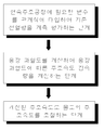
도 3은 본 발명의 실시예에 의한 연속주조 시 몰드 출구에서 형성되는 응고쉘의 두께 예측방법을 개략적으로 나타낸 순서도이다.
도 4는 몰드에서 주조속도와 몰드 전열량을 임의의 값으로 하여 수치해석한 결과를 나타낸 그래프이다.1 is a conceptual view showing a continuous casting machine according to an embodiment of the present invention, focusing on a molten steel flow.
Fig. 2 is a conceptual diagram showing the distribution of molten steel in the mold and its adjacent portion in Fig. 1. Fig.
3 is a flowchart schematically illustrating a method of predicting a thickness of a solidified shell formed at a mold exit during continuous casting according to an embodiment of the present invention.
4 is a graph showing the results of numerical analysis in which the casting speed and the mold heat quantity in the mold are arbitrary values.
이하, 첨부된 도면을 참조하여 본 발명의 바람직한 실시예를 상세하게 설명한다. 도면들 중 동일한 구성요소들은 가능한 어느 곳에서든지 동일한 부호로 표시한다. 또한 본 발명의 요지를 불필요하게 흐릴 수 있는 공지 기능 및 구성에 대한 상세한 설명은 생략한다.Hereinafter, preferred embodiments of the present invention will be described in detail with reference to the accompanying drawings. In the drawings, the same components are denoted by the same reference symbols whenever possible. In the following description, well-known functions or constructions are not described in detail since they would obscure the invention in unnecessary detail.
도 1은 본 발명의 실시예와 관련된 연속주조기를 용강의 흐름을 중심으로 나타낸 개념도이다.1 is a conceptual view showing a continuous casting machine according to an embodiment of the present invention, focusing on the flow of molten steel.
연속주조(continuous casting)는 용융금속을 바닥이 없는 몰드(Mold)에서 응고시키면서 연속적으로 주편 또는 강괴(steel ingot)를 뽑아내는 주조법이다. 연속주조는 정사각형, 직사각형 또는 원형 등 단순한 단면형의 긴 제품과 주로 압연용 소재인 슬라브, 블룸 또는 빌릿을 제조하는 데 이용된다.Continuous casting is a casting process in which a molten metal is continuously cast into a bottomless mold while continuously drawing a steel ingot or steel ingot. Continuous casting is used to manufacture slabs, blooms, or billets that are primarily rolled materials and long products of simple cross-section, such as square, rectangular, or circular.
연속주조기는 래들(10)과 턴디쉬(20), 몰드(30), 2차냉각대(60 및 65), 및 핀치롤(70)을 포함할 수 있다.The continuous casting machine may include the
턴디쉬(Tundish, 20)는 래들(Ladle, 10)로부터 용융금속을 받아 몰드(Mold, 30)로 용융금속을 공급하는 용기이다. 래들(10)은 한 쌍으로 구비되어, 교대로 용강을 받아서 턴디쉬(20)에 공급하게 된다. 턴디쉬(20)에서는 몰드(30)로 흘러드는 용융금속의 공급 속도조절, 각 몰드(30)로 용융금속 분배, 용융금속의 저장, 슬래그 및 비금속 개재물(介在物)의 분리 등이 이루어진다. A tundish 20 is a container for receiving molten metal from a
몰드(30)는 통상적으로 수냉식 구리제이며, 수강된 용강이 1차 냉각되게 한다. 몰드(30)는 구조적으로 마주보는 한 쌍의 면들이 개구된 형태로서 용강이 수용되는 중공부를 형성한다. 슬라브를 제조하는 경우에, 몰드(30)는 한 쌍의 장벽과, 장벽들을 연결하는 한 쌍의 단벽을 포함한다. 여기서, 단벽은 장벽보다 작은 넓이를 가지게 된다. 몰드(30)의 벽들, 주로는 단벽들은 서로에 대하여 멀어지거나 가까워지도록 회전되어 일정 수준의 테이퍼(Taper)를 가질 수 있다. Mold 30 is typically made of water-cooled copper and allows the molten steel taken to be first cooled. The
몰드(30)는 몰드에서 뽑아낸 연주주편이 일정 모양을 유지하고, 아직 응고가 덜 된 용융금속이 유출되지 않게 강한 응고각(凝固殼) 또는 응고쉘(Solidified Shell, 81)이 형성되도록 하는 역할을 한다. 수냉 구조에는 구리관을 이용하는 방식, 구리블록에 수냉홈을 뚫는 방식, 수냉홈이 있는 구리관을 조립하는 방식 등이 있다. The
몰드(30)는 용강이 몰드의 벽면에 붙는 것을 방지하기 위하여 오실레이션(oscillation, 왕복운동)되며, 오실레이션시 몰드(30)와 응고쉘(81)과의 마찰을 줄이고 타는 것을 방지하기 위해 파우더(Powder)와 같은 윤활제가 이용된다. 파우더는 몰드 내의 용융금속에 첨가되어 슬래그가 되며, 몰드(30)와 응고쉘의 윤활뿐만 아니라 몰드 내 용융금속의 산화·질화 방지와 보온, 용융금속의 표면에 떠오른 비금속 개재물의 흡수의 기능도 수행한다. The
2차 냉각대(60 및 65)는 몰드(30)에서 1차로 냉각된 용강을 추가로 냉각한다. 1차 냉각된 용강은 지지롤(60)에 의해 응고각이 변형되지 않도록 유지되면서, 물을 분사하는 스프레이수단(65)에 의해 직접 냉각된다. 연주주편의 응고는 대부분 상기 2차 냉각에 의해 이루어진다. The
인발장치(引拔裝置)는 연주주편이 미끄러지지 않게 뽑아내도록 몇 조의 핀치롤(미 도시됨)들을 이용하는 멀티드라이브방식 등을 채용하고 있다. 핀치롤은 용강의 응고된 선단부를 주조 방향으로 잡아당김으로써, 몰드(30)를 통과한 용강이 주조방향으로 연속적으로 이동할 수 있게 한다. The pulling device employs a multi-drive type or the like that uses several pairs of pinch rolls (not shown) so as to pull out the casting slides without slipping. The pinch roll pulls the solidified leading end portion of the molten steel in the casting direction, thereby allowing molten steel passing through the
연속적으로 생산되는 연주주편은 소정의 절단기(미 도시됨)에 의해 일정한 크기로 절단된다.The continuously produced musical piece is cut to a predetermined size by a predetermined cutter (not shown).
즉, 용강(M)은 래들(10)에 수용된 상태에서 턴디쉬(20)로 유동하게 된다. 이러한 유동을 위하여, 래들(10)에는 턴디쉬(20)를 향해 연장하는 슈라우드노즐(Shroud nozzle, 15)이 설치된다. 슈라우드노즐(15)은 용강(M)이 공기에 노출되어 산화·질화되지 않도록 턴디쉬(20) 내의 용강에 잠기도록 연장한다.That is, the molten steel M flows into the tundish 20 while being accommodated in the
턴디쉬(20) 내의 용강(M)은 몰드 내로 연장하는 침지노즐(Submerged Entry Nozzle, 25)에 의해 몰드 내로 유동하게 된다. 침지노즐(25)은 몰드(30)의 중앙에 배치되어, 침지노즐(25)의 양 토출구에서 토출되는 용강(M)의 유동이 대칭을 이룰 수 있도록 한다. 침지노즐(25)을 통한 용강(M)의 토출의 시작, 토출 속도, 및 중단은 침지노즐(25)에 대응하여 턴디쉬(20)에 설치되는 스토퍼(Stopper, 21)에 의해 결정된다. 구체적으로, 스토퍼(21)는 침지노즐(25)의 입구를 개폐하도록 침지노즐(25)과 동일한 라인을 따라 수직 이동될 수 있다. Molten steel M in the tundish 20 flows into the mold by a submerged
몰드 내의 용강(M)은 몰드(30)를 이루는 벽면에 접한 부분부터 응고하기 시작한다. 이는 용강(M)의 중심보다는 주변부가 수냉되는 몰드(30)에 의해 열을 잃기 쉽기 때문이다. 주변부가 먼저 응고되는 방식에 의해, 연주주편(80)의 주조 방향을 따른 뒷부분은 미응고 용강(82)이 응고쉘(81)에 감싸여진 형태를 이루게 된다.Molten steel (M) in the mold starts to solidify from the portion contacting the wall surface of the mold (30). This is because the periphery of the molten steel M is liable to lose heat by the water-cooled
핀치롤(70)이 완전히 응고된 연주주편(80)의 선단부(83)를 잡아당김에 따라, 미응고 용강(82)은 응고쉘(81)과 함께 주조 방향으로 이동하게 된다. 미응고 용강(82)은 위 이동 과정에서 냉각수를 분사하는 스프레이수단(65)에 의해 냉각된다. 이는 연주주편(80)에서 미응고 용강(82)이 차지하는 두께가 점차로 작아지게 한다. 연주주편(80)이 일 지점(85)에 이르면, 연주주편(80)은 전체 두께가 응고쉘(81)로 채워지게 된다. 응고가 완료된 연주주편(80)은 절단 지점(91)에서 일정 크기로 절단되어 슬라브 등과 같은 주편(P)으로 나누어진다.The non-solidified
몰드(30) 및 그와 인접한 부분에서의 용강(M)의 형태에 대해서는 도 2를 참조하여 설명한다. 도 2는 도 1의 몰드(30) 및 그와 인접한 부분에서의 용강(M)의 분포 형태를 보인 개념도이다.The shape of the molten steel M in the
도 2를 참조하면, 침지노즐(25)의 단부 측에는 통상적으로 도면상 좌우에 한 쌍의 토출구(25a)들이 형성된다. 몰드(30) 및 침지노즐(25) 등의 형태는 중심선(C)을 기준으로 대칭되는 것으로 가정하여, 본 도면에서는 좌측만을 표시한다.Referring to FIG. 2, a pair of
토출구(25a)에서 아르곤(Ar) 가스와 함께 토출되는 용강(M)은 화살표(A1, A2)로 표시된 바와 같이 상측을 향한 방향(A1)과 하측을 향한 방향(A2)으로 유동하는 궤적을 그리게 된다.The molten steel M discharged along with the argon (Ar) gas at the
몰드(30) 내부의 상부에는 파우더 공급기(50)로부터 공급된 파우더에 의해 파우더층(51)이 형성된다. 파우더층(51)은 파우더가 공급된 형태대로 존재하는 층과 용강(M)의 열에 의해 소결된 층(소결층이 미응고 용강(82)에 더 가깝게 형성됨)을 포함할 수 있다. 파우더층(51)의 하측에는 파우더가 용강(M)에 의해 녹아서 형성된 슬래그층 또는 액체 유동층(52)이 존재하게 된다. 액체 유동층(52)은 몰드(30) 내의 용강(M)의 온도를 유지하고 이물질의 침투를 차단한다. 파우더층(51)의 일부는 몰드(30)의 벽면에서 응고되어 윤활층(53)을 형성한다. 윤활층(53)은 응고쉘(81)이 몰드(30)에 붙지 않도록 윤활하는 기능을 한다. A
응고쉘(81)의 두께는 주조 방향을 따라 진행할수록 두꺼워진다. 응고쉘(81)의 몰드(30) 내에 위치한 부분은 두께가 얇으며, 몰드(30)의 오실레이션에 따라 자국(oscillation mark, 87)이 형성되기도 한다. 응고쉘(81)은 지지롤(60)에 의해 지지되며, 물을 분사하는 스프레이수단(65)에 의해 그 두께가 두꺼워진다. 응고쉘(81)은 두꺼워지다가 일부분이 볼록하게 돌출하는 벌징(bulging) 영역(88)이 형성되기도 한다.The thickness of the solidifying
도 3에 도시된 바와 같이 본 발명은 연속주조공정에서 주조되는 주편의 응고 두께를 일정하게 하기 위하여 연속주조공정에서 주조에 따른 변수를 관계식에 대입하여 주편 전열량을 계측 평가하는 단계와, 계산된 주편 전열량을 통해 몰드(30)를 냉각시키는 유출입 냉각수의 온도차(유출 - 유입)에 따른 용강 과열도를 계산하고, 계산된 용강 과열도에 따른 주조속도 감속량을 계산하는 단계와, 상기 계산된 주조속도 감속량으로 몰드(30)의 주조속도를 조절하는 단계를 통해 주편의 응고 두께를 일정하게 조절하게 된다.As shown in FIG. 3, in order to make the solidification thickness of the cast steel to be constant in the continuous casting process, a step of measuring and evaluating the casting heat quantity by substituting the variables according to the casting in the continuous casting process into the relational expression, Calculating a superheating degree of molten steel according to a temperature difference (outflow-inflow) of the outflow cooling water that cools the
상기 주편의 응고두께를 일정하게 하여 제조하는 이유는 주편의 품질을 일정하게 유지시켜 제조하기 위해서이다.The reason why the coagulation thickness of the cast steel is made constant is that the quality of the cast steel is kept constant.
상기 주편 전열량을 계측 평가하는 단계는 연속주조공정에서 몰드(30)에서 토출되는 용강(M)이 응고되어 주편으로 형성되는데 이 과정에서 주편의 응고에 관련하여 설정되는 조건들이 변수로 설정되고, 이러한 변수를 관계식에 대입하여 주편 전열량을 계측 평가하게 된다.In the step of measuring and evaluating the billet heat quantity, the molten steel M discharged from the
이때 사용되는 관계식은 다음과 같다.The relation used in this case is as follows.
관계식Relation

여기서, v는 주조속도[m/min]이고, Q는 몰드(30)를 냉각시키는 냉각수량[Nm3/hr]이며, ΔT는 몰드(30)를 냉각시키는 유출입 냉각수의 온도차[℃]이고, A는 주편/몰드(30)의 접촉면적[m2]이며, L은 주편/몰드(30)의 접촉길이[m]를 나타낸다.Here, v is the casting speed [m / min], Q is the amount of cooling water [Nm 3 / hr] for cooling the
도 4에 도시된 바와 같이 상기 주편 전열량이 계측 평가되면 계측 평가된 주편 전열량과 냉각시키는 유출입 냉각수의 온도차를 통해 용강 과열도를 계산하게 된다. 그리고, 이렇게 계산된 상기 용강 과열도에 따른 주조속도 감속량을 계산하게 된다.As shown in FIG. 4, when the billet heat quantity is measured and evaluated, the molten steel superheat degree is calculated through the temperature difference between the billet heat quantity measured and evaluated and the cooling water that is cooled. Then, the casting speed reduction amount according to the calculated molten steel superheating degree is calculated.
이때, 상기 용강 과열도는 용강(M)이 응고되는 온도를 초과하는 온도를 말한다.Here, the molten steel superheating degree refers to a temperature exceeding a temperature at which the molten steel M solidifies.
여기서, 상기 용강 과열도에 따른 주조속도 감속량은 몰드(30)를 냉각시키는 유출입 냉각수의 온도차와 주편 전열량을 대비하여 용강 과열도를 계산하게 된다.Here, the casting speed reduction rate according to the molten steel superheating degree is calculated by comparing the temperature difference of the outflow cooling water that cools the
이렇게 상기 주조속도 감속량이 용강 과열도에 따라 계산되면 이를 통해 몰드(30)에서 토출되는 용강(M)이 응고되어 형성되는 주편의 주조속도를 감속 또는 증가시켜 주편을 주조하게된다.When the casting speed reduction rate is calculated according to the superheating degree of the molten steel, the molten steel M discharged from the
이에 따라 상기 용강 과열도가 10℃ 상승되면 주조속도를 0.03m/min 감속시켜 주조되는 주편의 두께를 일정하게 유지시키게 된다.Accordingly, when the superheating degree of the molten steel is increased by 10 ° C, the casting speed is reduced by 0.03 m / min to maintain the thickness of the casting steel to be constant.
상기 용강 과열도가 10℃ 미만으로 상승될 때 주조속도를 감속시키게 되면 용강(M)의 온도가 높아 용강(M)이 응고되는 속도가 느려져 응고 두께가 얇아지게 될 수 있으며, 용강 과열도가 10℃를 초과하여 상승될때 주조속도를 감속시키면 용강(M)의 온도가 빨리 낮아지게 되어 용강(M)이 응고되는 속도가 빨라져 주편의 두께가 두꺼워 질 수 있다.When the superheating degree of the molten steel is increased to less than 10 ° C, if the casting speed is decreased, the molten steel M is coagulated at a slower rate due to a high temperature of the molten steel M, If the casting speed is lowered when the temperature rises above the temperature of the molten steel M, the temperature of the molten steel M is rapidly lowered, so that the molten steel M coagulates at a higher speed and the thickness of the casting may become thicker.
그리고, 용강 과열도가 10℃ 상승될 때 주조속도를 0.03m/min 미만으로 감속시키게 되면, 용강(M)의 온도가 낮아 용강(M)의 응고 속도가 빨라져 용강(M)이 응고되어 형성되는 주편의 두께가 두꺼워 질 수 있으며, 용강 과열도가 10℃ 상승될 때 주조속도를 0.03m/min을 초과하도록 감속시키면, 용강(M)의 온도가 높아 용강(M)의 응고 속도가 느려져 용강(M)이 응고되어 형성되는 주편의 두께가 얇아질 수 있게 된다.If the casting speed is lowered to less than 0.03 m / min when the molten steel superheating degree is increased by 10 캜, the molten steel M is cooled at a lower temperature to accelerate the solidification speed of the molten steel M, If the casting speed is reduced to exceed 0.03 m / min when the molten steel superheating degree is increased by 10 캜, the molten steel M will have a high temperature and the solidifying speed of the molten steel M will become slow, M) is solidified, the thickness of the cast steel can be thinned.
이러한 상기 용강 과열도는 주편 전열량과 몰드(30)를 냉각시키는 유출입 냉각수의 온도차에 비례하여 증가하게 되며, 주편 전열량과 주편의 주조속도와 반비례하여 감소된다.The superheating degree of the molten steel increases in proportion to the temperature difference between the billet heat transfer amount and the flow-out cooling water that cools the
즉, 몰드(30)를 냉각시키는 유출입 냉각수의 온도차가 크면 클수록 주편 전열량은 증가하게 되며, 이에 따라 용강 과열도 또한 증가하게 된다.That is, the larger the temperature difference of the flow-in / out cooling water for cooling the
그리고, 주조속도가 감소할수록 주편 전열량이 증가하게 되며, 이에 따른 용강 과열도 또한 증가하게 된다.And, as the casting speed decreases, the heat transfer amount of the cast steel increases and the molten steel superheat also increases accordingly.
이와 같이 구성된 본 발명은 연속주조시의 용강 과열도를 계측 평가하여 이를 통해 주조속도를 변경하므로, 용강이 응고되는 주편의 두께를 일정하게 유지시킬 수 있는 이점이 있다.According to the present invention configured as described above, since the superheating degree of the molten steel during the continuous casting is measured and evaluated to change the casting speed, there is an advantage that the thickness of the casting to which the molten steel coagulates can be kept constant.
상기와 같은 몰드 직하 응고두께 제어방법은 위에서 설명된 실시예들의 구성과 작동 방식에 한정되는 것이 아니다. 상기 실시예들은 각 실시예들의 전부 또는 일부가 선택적으로 조합되어 다양한 변형이 이루어질 수 있도록 구성될 수도 있다.
The above-described method of controlling the direct-under-mold coagulation thickness is not limited to the construction and operation of the embodiments described above. The embodiments may be configured so that all or some of the embodiments may be selectively combined so that various modifications may be made.
10: 래들 20: 턴디쉬
30: 몰드 50: 파우더 공급기
51: 파우더층 60: 지지롤
65: 스프레이 70: 핀치롤
80: 연주주편 81: 응고쉘
82: 미응고 용강 83: 선단부
85: 응고 완료점 91: 절단 지점10: Ladle 20: Tundish
30: mold 50: powder feeder
51: Powder layer 60: Support roll
65: spray 70: pinch roll
80: Casting Casting 81: Solidification Shell
82: non-solidified molten steel 83:
85: Solidification completion point 91: Cutting point
Claims (3)
상기 계산된 주편 전열량을 통해 몰드를 냉각시키는 유출입 냉각수의 온도차에 따른 용강 과열도를 계산하고, 상기 계산된 용강 과열도에 따른 주조속도 감속량을 계산하는 단계; 및
상기 계산된 주조속도 감속량으로 몰드의 주조속도를 조절하는 단계;를 포함하는 몰드 직하 응고두께 제어방법.
관계식

여기서, v는 주조속도이고, Q는 몰드를 냉각시키는 냉각수량이며, ΔT는 몰드를 냉각시키는 유출입 냉각수의 온도차(유출 - 유입)이고, A는 주편/몰드의 접촉면적이며, L은 주편/몰드의 접촉길이를 나타냄.
Measuring a casting calorie amount by substituting a casting-related variable into a relational expression in a continuous casting process;
Calculating a superheating degree of molten steel according to a temperature difference of the flow-in cooling water that cools the mold through the calculated bobble heat transfer amount, and calculating a casting speed reduction amount according to the calculated molten steel superheating degree; And
And adjusting the casting speed of the mold with the calculated casting speed reduction amount.
Relation
A is the contact area of the casting mold / mold, L is the casting / mold temperature, V is the casting speed, Q is the cooling water cooling the mold,? T is the temperature difference (outflow- Lt; / RTI >
상기 주조속도 감속량을 계산하는 단계는 상기 몰드를 냉각시키는 유출입 냉각수의 온도차와 주편 전열량을 대비하여 상기 용강 과열도를 계산하는 몰드 직하 응고두께 제어방법.
The method according to claim 1,
Wherein the step of calculating the casting speed reduction amount calculates the superheating degree of molten steel by comparing the temperature difference of the flow-in cooling water for cooling the mold with the casting heat amount.
상기 용강 과열도가 10℃ 상승되면 주조속도를 0.03m/min 감속시키는 몰드 직하 응고두께 제어방법.The method of claim 2,
Wherein the casting speed is reduced by 0.03 m / min when the molten steel superheating degree is increased by 10 ° C.
Priority Applications (1)
| Application Number | Priority Date | Filing Date | Title |
|---|---|---|---|
| KR1020120121979A KR20140056713A (en) | 2012-10-31 | 2012-10-31 | Method for controlling directly coagulation thickness of mold |
Applications Claiming Priority (1)
| Application Number | Priority Date | Filing Date | Title |
|---|---|---|---|
| KR1020120121979A KR20140056713A (en) | 2012-10-31 | 2012-10-31 | Method for controlling directly coagulation thickness of mold |
Publications (1)
| Publication Number | Publication Date |
|---|---|
| KR20140056713A true KR20140056713A (en) | 2014-05-12 |
Family
ID=50887800
Family Applications (1)
| Application Number | Title | Priority Date | Filing Date |
|---|---|---|---|
| KR1020120121979A KR20140056713A (en) | 2012-10-31 | 2012-10-31 | Method for controlling directly coagulation thickness of mold |
Country Status (1)
| Country | Link |
|---|---|
| KR (1) | KR20140056713A (en) |
-
2012
- 2012-10-31 KR KR1020120121979A patent/KR20140056713A/en not_active Application Discontinuation
Similar Documents
| Publication | Publication Date | Title |
|---|---|---|
| KR101400046B1 (en) | Manufacture method for high strength casting of ultra low carbon steel | |
| KR20120110584A (en) | Device for controlling cooling of mold for thin slab and method therefor | |
| KR101400044B1 (en) | Method for controlling casting speed in continuous casting | |
| KR101267341B1 (en) | Device for preventing breakout of solidified shell in continuous casting process and method therefor | |
| KR101368350B1 (en) | Device for prediction of carbon increase in molten steel and method thereof | |
| KR101368351B1 (en) | Predicting method for thickness of solidified shell on continuous casting process | |
| KR101505406B1 (en) | Method for predicting quality of slab | |
| KR101388056B1 (en) | Predicting method for quality of steel on continuous casting process | |
| KR20130099334A (en) | Method for producing high quality slab | |
| KR101388071B1 (en) | Cooling method of mold for continuous casting | |
| KR101435115B1 (en) | Method for reducing surface defect of slab | |
| KR101400047B1 (en) | Control method for casting of ultra low carbon steel | |
| KR20140056713A (en) | Method for controlling directly coagulation thickness of mold | |
| KR101435111B1 (en) | Method for predicting shrinkage of solidified shell in continuous casting process | |
| KR101368352B1 (en) | Method for controlling temperature of casting | |
| KR101435117B1 (en) | Method for stabilizing meniscus in continuous casting | |
| KR101466202B1 (en) | Controlling method for surface quality of slab | |
| KR101400036B1 (en) | Separatimg method for slab of high clean steel | |
| KR101435122B1 (en) | Controlling method for surface quality of ultra low carbon steel slab | |
| KR101435148B1 (en) | Manufacture method for high strength casting of ultra low carbon steel | |
| KR101443588B1 (en) | Method for predicting pin-hole defect of slab | |
| KR101400035B1 (en) | Method for producing high quality slab | |
| KR101204945B1 (en) | Device for controlling flow of molten steel in mold and method therefor | |
| KR101466197B1 (en) | Controlling method for surface quality of ultra low carbon steel slab | |
| KR101344902B1 (en) | Control method for quality of steel |
Legal Events
| Date | Code | Title | Description |
|---|---|---|---|
| A201 | Request for examination | ||
| E902 | Notification of reason for refusal | ||
| E902 | Notification of reason for refusal | ||
| E601 | Decision to refuse application |