KR20140056226A - Modular cutting tool holder and clamping mechanism therefor - Google Patents
Modular cutting tool holder and clamping mechanism therefor Download PDFInfo
- Publication number
- KR20140056226A KR20140056226A KR1020147002015A KR20147002015A KR20140056226A KR 20140056226 A KR20140056226 A KR 20140056226A KR 1020147002015 A KR1020147002015 A KR 1020147002015A KR 20147002015 A KR20147002015 A KR 20147002015A KR 20140056226 A KR20140056226 A KR 20140056226A
- Authority
- KR
- South Korea
- Prior art keywords
- camshaft
- follower
- tool holder
- body portion
- cutting tool
- Prior art date
Links
Images


Classifications
-
- B—PERFORMING OPERATIONS; TRANSPORTING
- B23—MACHINE TOOLS; METAL-WORKING NOT OTHERWISE PROVIDED FOR
- B23B—TURNING; BORING
- B23B29/00—Holders for non-rotary cutting tools; Boring bars or boring heads; Accessories for tool holders
- B23B29/04—Tool holders for a single cutting tool
-
- B—PERFORMING OPERATIONS; TRANSPORTING
- B23—MACHINE TOOLS; METAL-WORKING NOT OTHERWISE PROVIDED FOR
- B23B—TURNING; BORING
- B23B29/00—Holders for non-rotary cutting tools; Boring bars or boring heads; Accessories for tool holders
- B23B29/04—Tool holders for a single cutting tool
- B23B29/046—Tool holders for a single cutting tool with an intermediary toolholder
-
- B—PERFORMING OPERATIONS; TRANSPORTING
- B23—MACHINE TOOLS; METAL-WORKING NOT OTHERWISE PROVIDED FOR
- B23B—TURNING; BORING
- B23B31/00—Chucks; Expansion mandrels; Adaptations thereof for remote control
- B23B31/02—Chucks
- B23B31/10—Chucks characterised by the retaining or gripping devices or their immediate operating means
- B23B31/11—Retention by threaded connection
-
- B—PERFORMING OPERATIONS; TRANSPORTING
- B23—MACHINE TOOLS; METAL-WORKING NOT OTHERWISE PROVIDED FOR
- B23B—TURNING; BORING
- B23B2210/00—Details of turning tools
- B23B2210/08—Tools comprising intermediary toolholders
-
- B—PERFORMING OPERATIONS; TRANSPORTING
- B23—MACHINE TOOLS; METAL-WORKING NOT OTHERWISE PROVIDED FOR
- B23B—TURNING; BORING
- B23B2231/00—Details of chucks, toolholder shanks or tool shanks
- B23B2231/02—Features of shanks of tools not relating to the operation performed by the tool
- B23B2231/0204—Connection of shanks to working elements of tools
-
- B—PERFORMING OPERATIONS; TRANSPORTING
- B23—MACHINE TOOLS; METAL-WORKING NOT OTHERWISE PROVIDED FOR
- B23B—TURNING; BORING
- B23B2260/00—Details of constructional elements
- B23B2260/02—Cams
-
- Y—GENERAL TAGGING OF NEW TECHNOLOGICAL DEVELOPMENTS; GENERAL TAGGING OF CROSS-SECTIONAL TECHNOLOGIES SPANNING OVER SEVERAL SECTIONS OF THE IPC; TECHNICAL SUBJECTS COVERED BY FORMER USPC CROSS-REFERENCE ART COLLECTIONS [XRACs] AND DIGESTS
- Y10—TECHNICAL SUBJECTS COVERED BY FORMER USPC
- Y10T—TECHNICAL SUBJECTS COVERED BY FORMER US CLASSIFICATION
- Y10T407/00—Cutters, for shaping
- Y10T407/22—Cutters, for shaping including holder having seat for inserted tool
- Y10T407/227—Cutters, for shaping including holder having seat for inserted tool with separate means to fasten tool seat to holder
-
- Y—GENERAL TAGGING OF NEW TECHNOLOGICAL DEVELOPMENTS; GENERAL TAGGING OF CROSS-SECTIONAL TECHNOLOGIES SPANNING OVER SEVERAL SECTIONS OF THE IPC; TECHNICAL SUBJECTS COVERED BY FORMER USPC CROSS-REFERENCE ART COLLECTIONS [XRACs] AND DIGESTS
- Y10—TECHNICAL SUBJECTS COVERED BY FORMER USPC
- Y10T—TECHNICAL SUBJECTS COVERED BY FORMER US CLASSIFICATION
- Y10T409/00—Gear cutting, milling, or planing
- Y10T409/30—Milling
- Y10T409/30952—Milling with cutter holder
-
- Y—GENERAL TAGGING OF NEW TECHNOLOGICAL DEVELOPMENTS; GENERAL TAGGING OF CROSS-SECTIONAL TECHNOLOGIES SPANNING OVER SEVERAL SECTIONS OF THE IPC; TECHNICAL SUBJECTS COVERED BY FORMER USPC CROSS-REFERENCE ART COLLECTIONS [XRACs] AND DIGESTS
- Y10—TECHNICAL SUBJECTS COVERED BY FORMER USPC
- Y10T—TECHNICAL SUBJECTS COVERED BY FORMER US CLASSIFICATION
- Y10T82/00—Turning
- Y10T82/25—Lathe
- Y10T82/2585—Tool rest
- Y10T82/2589—Quick release tool or holder clamp
Abstract
금속-가공 기계를 위한 모듈형 컷팅 공구 홀더 부분(16, 18)이 상보적인 모듈형 컷팅 공구 홀더 부분의 상응하는 제 2 결합 면과 클램핑 결합하도록 구성된 제 1 결합 면을 포함한다. 제 1 결합 면이 베이스 표면 및 정확하게 4개의 돌출하는 돌출부 또는 정확하게 4개의 리세스 형태의 상호록킹 요소를 포함한다. 각각의 상호록킹 요소가 상기 베이스 표면으로부터 이격되는 비-접촉 표면을 포함한다. 상기 비-접촉 표면은 2개의 대향 엣지, 및 상기 2개의 대향 엣지 중 각각의 하나로부터 상기 베이스 표면까지 연장하고 그리고 상기 클램핑 결합을 위해서 구성된 2개의 접촉지지 표면을 포함하고, 상기 2개의 대향 엣지들 사이에서 상기 비-접촉 표면이 연장한다. A modular cutting tool holder portion (16, 18) for a metal-working machine includes a first mating surface configured to clamp-mate with a corresponding second mating surface of a complementary modular cutting tool holder portion. The first engagement surface includes a base surface and exactly four protruding protrusions or exactly four recessed interlocking elements. Each interlocking element includes a non-contact surface spaced from the base surface. Wherein the non-contact surface includes two opposing edges and two contact support surfaces extending from each one of the two opposing edges to the base surface and configured for the clamping engagement, the two opposing edges The non-contact surface extends between the two surfaces.
Description
본원의 청구 대상은, 헤드 부분 및 본체 부분을 가지는 금속-가공 기계들을 위한 모듈형 컷팅 공구 홀더, 그리고 상기 헤드 부분을 상기 본체 부분에 고정하기 위한 클램핑 메커니즘에 관한 것이다. 클램핑 메커니즘은, 상기 헤드 부분이 상기 본체 부분에 고정되는 클램핑된 위치, 및 상기 헤드 부분이 상기 본체 부분으로부터 제거될 수 있는 언클램핑된 위치를 취할 수 있다. What is claimed is a modular cutting tool holder for metal-working machines having a head portion and a body portion, and a clamping mechanism for securing the head portion to the body portion. The clamping mechanism may take a clamped position in which the head portion is secured to the body portion and an unclamped position in which the head portion can be removed from the body portion.
모듈형 컷팅 공구 홀더가, 하나의 위치에서 서로에 대해서 고정될 수 있고 그리고 다른 위치에서 서로로부터 탈착될 수 있는 헤드 부분 및 본체 부분을 포함한다. 헤드 부분은 적어도 하나의 커팅 요소로 구성된다. 적어도 하나의 컷팅 요소가 교체될 필요가 있을 때, 헤드 부분이 본체 부분으로부터 탈착되고 그리고 상이한 컷팅 요소 또는 요소들을 가지는 새로운 헤드 부분이 본체 부분에 고정될 수 있다.Modular cutting tool holders include a head portion and a body portion that can be fixed relative to each other at one location and can be detached from each other at other locations. The head portion comprises at least one cutting element. When at least one cutting element needs to be replaced, the head portion is detached from the body portion and a new head portion having different cutting elements or elements can be secured to the body portion.
US 제5,873,682호는 클램핑 메커니즘을 가지는 모듈형 컷팅 공구 홀더를 개시한다. US 5,873,682 discloses a modular cutting tool holder having a clamping mechanism.
본원 발명의 목적은 새롭고 개선된 모듈형 컷팅 공구 홀더 및/또는 모듈형 컷팅 공구 홀더의 부분 및/또는 모듈형 컷팅 공구 홀더를 위한 클램핑 메커니즘을 제공하는 것이다. It is an object of the invention to provide a new and improved modular cutting tool holder and / or a part of a modular cutting tool holder and / or a clamping mechanism for a modular cutting tool holder.
본원의 청구 대상의 제 1 양태에 따라서, 금속-가공 기계를 위한 모듈형 컷팅 공구 홀더가 제공되고, 상기 모듈형 컷팅 공구 홀더는 적어도 하나의 컷팅 요소를 홀딩하도록 구성되고 그리고 본체 부분, 헤드 부분 및 클램핑 메커니즘을 포함하고, 상기 클램핑 메커니즘은 상기 헤드 부분이 상기 본체 부분에 고정되는 클램핑된 위치와 상기 헤드 부분이 상기 본체 부분으로부터 제거가능한 언클램핑된 위치 사이에서 이동되도록 구성되고; 상기 클램핑 메커니즘은 관통-보어로 형성된 종동부 및 상기 종동부의 관통-보어를 통해서 연장하는 캠 샤프트를 포함하고, 상기 캠 샤프트는, 회전 운동 중에, 상기 종동부 관통-보어와 결합하도록 구성되고; 상기 결합은 상기 종동부의 선형 운동을 초래하며, 그에 의해서 클램핑 메커니즘을 클램핑된 위치 또는 언클램핑된 위치로 이동시킨다. According to a first aspect of the claimed subject matter there is provided a modular cutting tool holder for a metal-working machine, the modular cutting tool holder being configured to hold at least one cutting element and having a body portion, A clamping mechanism configured to move between a clamped position in which the head portion is secured to the body portion and an unclamped position in which the head portion is removable from the body portion; Wherein the clamping mechanism comprises a follower formed by a through bore and a cam shaft extending through the through bore of the follower, the cam shaft being configured to engage the follower through bore during rotational movement; The engagement results in a linear movement of the follower, thereby moving the clamping mechanism to a clamped or unclamped position.
본원의 청구 대상의 제 2 양태에 따라서, 모듈형 컷팅 공구 홀더를 위한 헤드 부분이 제공되고, 상기 헤드 부분은 컷팅 요소를 홀딩하도록 구성되고, 그리고 상호록킹(interlocking) 요소로 형성된 결합 면 및 상기 결합 면으로부터 내부에서 연장하는 록킹 보어를 포함하고; 헤드 부분 축이 상기 헤드 부분을 통해서 그리고 상기 록킹 보어와 동축적으로 연장하고; 상기 록킹 보어가 하나 이상의 홈 또는 바람직하게 헤드 부분 축을 따라서 서로 평행하고 그리고 서로에 대해서 축방향으로 이격된 복수의 홈으로 형성된다. According to a second aspect of the claimed subject matter there is provided a head portion for a modular cutting tool holder, the head portion being configured to hold a cutting element, and having a mating surface formed of an interlocking element, A locking bore extending internally from the face; A head part shaft extending through said head part and coaxially with said locking bore; The locking bores are formed by a plurality of grooves parallel to each other and axially spaced apart from each other along one or more grooves or preferably a head partial axis.
본원의 청구 대상의 제 3 양태에 따라서, 모듈형 컷팅 공구 홀더를 위한 종동부가 제공되고, 상기 종동부가 그 중심을 통해서 길이방향으로 연장하는 종동부 축을 가지는 세장형이고, 상기 종동부가 종동부 본체 부분 및 상기 종동부 본체 부분으로부터 연장하는 종동부 헤드 부분을 포함하고; 상기 종동부 헤드 부분은 하나 이상의 리브(rib) 또는 바람직하게 상기 종동부 축을 따라서 서로 평행하고 그리고 서로에 대해서 축방향으로 이격된 복수의 리브를 포함한다. According to a third aspect of the claimed subject matter there is provided a follower for a modular cutting tool holder, said follower being elongate with a longitudinal axis extending longitudinally through its center, And a follower head portion extending from the follower body portion; The follower head portion includes one or more ribs or a plurality of ribs parallel to one another and axially spaced apart from one another, preferably along the follower axis.
본원의 청구 대상의 제 4 양태에 따라서, 상기 제 2 양태에 따른 헤드 부분 및 상기 제 3 양태에 따른 종동부를 포함하는 모듈형 컷팅 공구 홀더가 제공된다.According to a fourth aspect of the presently claimed subject matter, there is provided a modular cutting tool holder comprising a head portion according to the second aspect and a follower according to the third aspect.
본원의 청구 대상의 제 5 양태에 따라서, 금속-가공 기계를 위한 모듈형 컷팅 공구 홀더가 제공되고, 상기 모듈형 컷팅 공구 홀더는 상보적인 모듈형 컷팅 공구 홀더 부분의 상응하는 제 2 결합 면과 클램핑 결합하도록 구성된 제 1 결합 면을 포함하고; 상기 제 1 결합 면이 베이스 표면 및 정확하게 4개의 돌출하는 돌출부 또는 정확하게 4개의 리세스 형태의 상호록킹 요소를 포함하고; 각각의 상호록킹 요소가 상기 베이스 표면으로부터 이격되고 2개의 대향 엣지를 가지는 비-접촉 표면, 및 상기 2개의 대향 엣지 중 각각의 하나로부터 상기 베이스 표면까지 연장하고 그리고 상기 클램핑 결합을 위해서 구성된 2개의 접촉지지 표면을 포함하고, 상기 2개의 대향 엣지들 사이에서 상기 비-접촉 표면이 연장한다. According to a fifth aspect of the claimed subject matter there is provided a modular cutting tool holder for a metal-working machine, the modular cutting tool holder having a corresponding second mating surface of a complementary modular cutting tool holder portion, A first mating surface configured to mate; Said first engagement surface including a base surface and exactly four projecting protrusions or exactly four recessed interlocking elements; Each interlocking element having a non-contact surface spaced from the base surface and having two opposing edges and two contacts extending from each one of the two opposing edges to the base surface and configured for the clamping engagement, Wherein the non-contact surface extends between the two opposing edges.
상기 부분이 모듈형 컷팅 공구 홀더의 헤드 부분 또는 본체 부분일 수 있다.The portion may be the head portion or the body portion of the modular cutting tool holder.
본원의 청구 대상의 제 6 양태에 따라서, 각각이 제 5 양태에 따른 또는 전술한 또는 후술하는 임의 특징을 각각 가지는, 본체 부분 및 상보적인 헤드 부분을 포함하는 금속-가공 기계를 위한 모듈형 컷팅 공구 홀더가 제공되고; 상기 본체 부분 및 헤드 부분 중 하나가 정확하게 4개의 돌출하는 돌출부 형태의 상호록킹 요소를 포함하고, 그리고 상기 본체 및 헤드 부분 중 다른 하나가 정확하게 4개의 상응하는 리세스 형태의 상호록킹 요소를 포함하며; 그리고 상기 본체와 상기 헤드 부분 사이의 유일한 접촉이 상기 상호록킹 요소의 접촉지지 표면을 통해서 이루어진다. According to a sixth aspect of the presently claimed subject matter, there is provided a modular cutting tool for a metal-working machine, comprising a body part and a complementary head part, each having a certain feature according to the fifth aspect, A holder is provided; Wherein one of the body portion and the head portion includes exactly four protruding protrusion-shaped interlocking elements, and the other of the body and the head portion comprises exactly four corresponding recessed interlocking elements; And the only contact between the body and the head portion is through the contact support surface of the interlocking element.
본원의 청구 대상의 제 7 양태에 따라서, 캠 샤프트의 부분을 내부에 수용하기 위한 클램핑 메커니즘 개구부를 가지는 공구 홀더 본체 부분이 제공되고, 상기 클램핑 메커니즘은: 상기 개구부 내에 구속부를 형성하는 제 1 및 제 2의 이격된 안착 영역, 상기 제 1 안착 영역으로부터 상기 제 2 안착 영역까지 연장하고 그리고 상기 구속부의 제 1 측부 상에 형성된 주요 둘레 엣지, 상기 제 1 안착 영역으로부터 상기 제 2 안착 영역까지 연장하고 그리고 상기 구속부의 제 1 측부와 구분되는 상기 구속부의 제 2 측부 상에 형성되는 부가적인 둘레 엣지를 포함한다. According to a seventh aspect of the presently claimed subject matter there is provided a tool holder body portion having a clamping mechanism opening for receiving a portion of a camshaft therein, the clamping mechanism comprising: a first and a second clamping mechanism, 2, a main perimeter edge extending from the first seating area to the second seating area and formed on the first side of the restraint, a second peripheral edge extending from the first seating area to the second seating area, And an additional perimeter edge formed on the second side of the restricting portion which is separated from the first side of the restricting portion.
본원의 청구 대상의 제 8 양태에 따라서, 공구 홀더 헤드 부분을 홀딩하기 위한 모듈형 컷팅 공구 홀더가 제공되고, 상기 모듈형 컷팅 공구 홀더는 캠 샤프트 및 상기 캠 샤프트의 제 1 부분을 수용하도록 구성된 클램핑 메커니즘 개구부를 가지는 본체 부분을 포함하고; 상기 클램핑 메커니즘이 상기 개구부 내에 구속부를 형성하는 제 1 및 제 2의 이격된 안착 영역, 및 상기 제 1 안착 영역으로부터 상기 제 2 안착 영역까지 연장하고 그리고 상기 구속부의 제 1 측부 상에 형성되는 주요 둘레 엣지를 포함하고; 상기 캠 샤프트의 제 1 부분이 구속부의 제 1 측부에 적어도 부분적으로 위치되고; 그리고 상기 구속부의 치수가 상기 캠 샤프트의 통과를 제한하기 위한 상기 캠 샤프트의 제 1 부분의 외부 치수 보다 작다. According to an eighth aspect of the presently claimed subject matter there is provided a modular cutting tool holder for holding a toolholder head portion, the modular cutting tool holder comprising a camshaft and a clamping portion configured to receive a first portion of the camshaft A body portion having a mechanism opening; Wherein the clamping mechanism comprises first and second spaced apart seating areas defining a restraining portion in the opening and a plurality of spaced-apart primary walls extending from the first seating area to the second seating area and formed on the first side of the restraining part, Includes an edge; The first portion of the camshaft is at least partially located on the first side of the restraining portion; And the dimension of the restricting portion is smaller than the outer dimension of the first portion of the camshaft for limiting the passage of the camshaft.
본원의 청구 대상이, 비제한적으로 본체 부분, 헤드 부분, 종동부, 캠 샤프트, 클램핑 메커니즘, 클램핑 메커니즘 개구부 및 그 상호록킹 배열체를 포함하는, 모듈형 컷팅 공구 홀더 및 그 요소들의 발명적인 양태에 관한 것임을 이해할 수 있을 것이다. 각각의 양태가 독립적으로 발명적이지만, 그 양태가 또한 이하에서 구체적으로 설명하는 바와 같이 단일 모듈형 컷팅 공구 홀더의 일부일 수 있다. SUMMARY OF THE INVENTION It is an object of the present invention to provide a modular cutting tool holder and its elements in an inventive aspect, including but not limited to a body part, a head part, a follower part, a cam shaft, a clamping mechanism, a clamping mechanism opening and an interlocking arrangement thereof It can be understood that While each aspect is independently inventive, the embodiment may also be part of a single modular cutting tool holder, as will be described in greater detail below.
전술한 내용이 요약이고, 그리고 상기 양태 중의 임의의 양태와 관련하여 설명된 또는 이하에서 설명된 다른 임의의 특징을 더 포함할 수 있다는 것을 이해할 수 있을 것이다. 구체적으로, 이하의 특징은, 단독으로 또는 조합되어, 상기 양태 중 임의의 양태에 적용될 수 있을 것이다. It is to be understood that the foregoing is a summary and may further include any other features described in connection with any of the above aspects or described below. Specifically, the following features, alone or in combination, may be applied to any of the above embodiments.
A. 캠 샤프트 및 종동부가 클램핑 메커니즘의 유일한 요소가 될 수 있다. 바람직하게, 클램핑 메커니즘이 편향 부재를 포함할 수 있다. 보다 더 바람직하게, 장력 스프링을 포함하는 실시예에서, 클램핑 메커니즘의 부가적인 요소가 편향 부재를 앵커링(anchor)하도록 구성된 나사일 수 있다. 적의 수의 성분이 종종 보다 신뢰가능한 제품을 초래할 수 있다는 것을 이해할 수 있을 것이다. 따라서, 클램핑 메커니즘이, 요구되는 전술한 구성에 의존하여, 단지 2개 또는 3개 또는 4개의 부재를 포함할 수 있다. 임의 경우에, 클램핑 메커니즘이 2개 내지 4개의 요소를 포함할 수 있다. A. The camshaft and follower can be the only element of the clamping mechanism. Preferably, the clamping mechanism may comprise a biasing member. Even more preferably, in an embodiment including a tension spring, an additional element of the clamping mechanism may be a screw configured to anchor the biasing member. It will be appreciated that a number of components of the enemy can often result in more reliable products. Thus, the clamping mechanism may comprise only two or three or four members, depending on the required configuration as described above. In any case, the clamping mechanism may comprise from two to four elements.
B. 캠 샤프트가, 캠 샤프트의 회전 운동만을 허용하는 배열로 본체 부분에 장착될 수 있다. 캠 샤프트를 본체 부분에 장착하는 것은 캠 샤프트의 2개의 대향 단부에서 이루어질 수 있다. 2개의 대향 단부가 본체 부분의 2개의 대향 측부에 위치될 수 있다. 그러한 배열이 안정적인 동작을 제공할 수 있다는 것을 이해할 수 있을 것이다. B. The camshaft can be mounted on the body portion in an arrangement that allows only rotational movement of the camshaft. Mounting the camshaft to the body portion can be done at two opposite ends of the camshaft. Two opposing ends may be located on two opposing sides of the body portion. It will be appreciated that such an arrangement may provide stable operation.
C. 캠 샤프트가 클램핑된 위치 및 언클램핑된 위치 모두에서, 그리고 그 사이의 임의의 전이적인 위치에서 종동부 관통-보어를 통해서 연장하도록 구성될 수 있다. 그러한 구성이, 종동부가 본체 부분으로부터 원치않게 빠져나오는 것을 방지하는 것을 보조할 수 있다는 것을 이해할 수 있을 것이다. C. The camshaft may be configured to extend through the follower through-bores at both the clamped and unclamped positions and in any transitional position therebetween. It will be appreciated that such a configuration may assist in preventing the follower from unwinding from the body portion.
D. 종동부 관통-보어가 캠 샤프트의 곡선형 섹션과 결합하도록 구성된 평면형 섹션을 포함할 수 있다. 캠 샤프트의 종동부 관통-보어와의 결합이 단지 종동부 관통-보어의 평면형 섹션으로 이루어질 수 있다. D. Follower Perforations - The bore may include a planar section configured to engage a curved section of the camshaft. The coupling with the follower-bore of the camshaft may consist only of a planar section of the follower-through bore.
E. 캠 샤프트가 종동부 관통-보어의 평면형 섹션과 결합하도록 구성된 평면형 섹션을 포함할 수 있다. E. The camshaft may include a planar section configured to engage a planar section of the follower-bore.
F. 캠 샤프트의 곡선형 섹션이 곡선형 하위-섹션을 포함할 수 있고, 각각의 곡선형 하위-섹션이 변화되는 곡률의 레이트를 가진다. 각각의 곡선형 하위-섹션의 변화되는 곡률의 레이트가 나선형 형상을 형성할 수 있다. 각각의 곡선형 하위-섹션이 대칭적일 수 있고 그리고 곡선형 섹션과 교차하는 양분 평면의 대향 측부들 상에 배치될 수 있다. 각각의 곡선형 하위-섹션이 종동부 관통-보어와 결합하도록 구성될 수 있고 그리고 캠 샤프트가 시계방향 또는 반시계방향으로 회전되도록 구성되어 컷팅 공구 홀더가 클램핑된 위치 또는 언클램핑된 위치로 이동하게 할 수 있다. 그러한 배열은, 조작자가 임의 방향으로의 회전에 의해서(즉, 특정 방향을 기억할 필요가 없이) 위치를 변화시키길 원할 때 유리할 수 있다. 캠 샤프트의 약 1/4 회전시에 공구 홀더가 클램핑된 위치 또는 언클램핑된 위치가 될 수 있게 허용하도록, 각각의 곡선형 하위-섹션의 곡률이 구성될 수 있다. 이러한 구성은 위치의 신속한 변화를 가능하게 할 수 있다. 대안적으로, 캠 샤프트의 곡선형 섹션이 단일의, 그러한 변화되는 곡률의 레이트(즉, 하위-섹션으로 분할되지 않는다)를 가질 수 있다. 변화되는 곡률의 레이트가 나선형 형상, 바람직하게 아르키메데스 나선을 형성한다. 그러한 배열은, 조작자가 헤드 부분 및 본체 부분을 해제 및 고정하는 각각의 동작을 위해서 단일의 규정된 방향의 회전을 가지고자 하는 경우에 유리할 수 있다. 그러한 구성은, 캠 샤프트의 약 절반 회전 시에, 공구 홀더가 클램핑된 위치 또는 언클램핑된 위치가 될 수 있게 허용할 수 있다. 바람직하게, 곡선형 섹션 또는 섹션들이 아르키메데스 나선(들)을 형성한다.F. The curved section of the camshaft may include a curved sub-section, and each curved sub-section has a rate of change of curvature. The rate of change of the curvature of each curved sub-section may form a spiral shape. Each curved sub-section may be symmetrical and may be disposed on opposite sides of the nutrient plane intersecting the curved section. Each curved sub-section may be configured to engage a follower through-bore and the camshaft may be configured to be rotated clockwise or counterclockwise to move the cutting tool holder to a clamped or unclamped position can do. Such an arrangement may be advantageous when the operator wishes to change position by rotation in any direction (i.e., without having to remember a particular direction). The curvature of each curved sub-section may be configured to allow the toolholder to be in a clamped or unclamped position at about 1/4 turn of the camshaft. Such a configuration can enable rapid change of position. Alternatively, the curved sections of the camshaft may have a single, varying rate of curvature (i. E. Not divided into sub-sections). The rate of change of curvature forms a spiral shape, preferably an Archimedes spiral. Such an arrangement may be advantageous if the operator wishes to have a single defined direction of rotation for each operation of releasing and securing the head and body portions. Such a configuration may allow the tool holder to be in the clamped or unclamped position at about half a turn of the camshaft. Preferably, the curved sections or sections form the Archimedes spiral (s).
G. 모듈형 컷팅 공구 홀더가 캠 샤프트를 포함하는 클램핑 메커니즘, 및 캠 샤프트의 시계방향 또는 반시계방향 회전 시에 클램핑 결합을 유도하도록 구성된 클램핑 메커니즘을 포함할 수 있다. 시계방향 또는 반시계방향 회전이 캠 샤프트의 1/4 회전일 수 있다. G. The modular cutting tool holder may include a clamping mechanism including a camshaft and a clamping mechanism configured to induce a clamping engagement upon clockwise or counterclockwise rotation of the camshaft. The clockwise or counterclockwise rotation may be a quarter turn of the camshaft.
H. 종동부 또는 캠 샤프트가 서로에 대한 운동을 중단시키기 위한 돌출하는 기계적 정지부로 형성될 수 있다(예를 들어, 기계적인 정지부가 상부 부분에 인접할 수 있고, 즉 도 6c의 예시적인 실시예에서 도시된 리세스의 위치 내에 있을 수 있고, 그리고 캠 샤프트의 제 2 단부가 상기 기계적인 정지부와 결합하기 위해서 성장 패턴(growth pattern)을 따를 수 있다).H. The follower or camshaft may be formed as a protruding mechanical stop for interrupting motion relative to each other (e.g., a mechanical stop may be adjacent to the top portion, i.e., the exemplary embodiment of Figure 6C And the second end of the camshaft may follow a growth pattern for engagement with the mechanical stop).
I. 캠 샤프트가, 제거 배열체가 배치되는 수용 리세스를 포함할 수 있다. 제거 배열체가 적어도 하나의 측방향으로 연장하는 앵커링 벽 부분을 포함할 수 있다. I. The camshaft may include a receiving recess in which the removal arrangement is disposed. The removal arrangement may include at least one laterally extending anchoring wall portion.
J. 모듈형 컷팅 공구 홀더, 또는 보다 구체적으로 그 클램핑 메커니즘이 편향 부재를 포함할 수 있다. 상기 헤드 부분이 본체 부분 상에 안착되고 그리고 본체 부분이 수직 배향으로 홀딩될 때, 상기 본체 부분을 상기 헤드 부분으로부터 이격시키기에 충분한 편향력을 제공하도록 편향 부재가 구성될 수 있다. 그러한 구성은, 2개의 부분이 단지 회전력의 인가에 의해서 서로에 대해서 회전될 수 있도록 이루어질 수 있다. 그 대신에, 편향 부재가 장력 스프링의 형태일 수 있다. 그러한 경우에, 편향 부재가 본체 부분 및 헤드 부분을 함께 끌어당기고 그리고 본체 부분 및 헤드 부분을 정적인(static) 클램핑된 위치에서 정렬시키기 위한 편향력을 제공하도록 구성될 수 있다. J. A modular cutting tool holder, or more specifically its clamping mechanism, may include a biasing member. The biasing member may be configured to provide a biasing force sufficient to disengage the body portion from the head portion when the head portion is seated on the body portion and the body portion is held in a vertical orientation. Such a configuration can be made such that the two parts can be rotated relative to each other only by the application of the rotational force. Instead, the biasing member may be in the form of a tension spring. In such cases, the biasing member may be configured to provide biasing forces to pull the body portion and head portion together and align the body portion and head portion in a static clamped position.
K. 편향 부재는 클램핑된 위치 및 언클램핑된 위치 모두에서, 그리고 그 사이의 임의의 전이적인 위치에서 종동부 상으로 연속적인 편향력을 인가하도록 구성될 수 있다. 그러한 연속적인 편향력은 캠 샤프트가 본체 부분으로부터 원치않게 빠져나오는 것을 방지하는데 도움을 줄 수 있다. K. The biasing member may be configured to apply a continuous biasing force on the driven portion at both the clamped and unclamped positions and at any transient position therebetween. Such a continuous biasing force can help prevent the camshaft from unwanted escape from the body portion.
L. 본체 부분 및 헤드 부분이 4개의 상이하게 회전된 위치에서 서로 클램핑 결합하도록 구성될 수 있다. 모듈형 컷팅 공구 홀더가 상기 본체 부분 또는 헤드 부분의 연속적인 1/4 회전을 통해서 4개의 상이한 회전된 위치를 가질 수 있도록 구성될 수 있다. L. The main body part and the head part can be configured to be clamped to each other at four differently rotated positions. The modular cutting tool holder can be configured to have four different rotated positions through successive quarter turns of the body portion or head portion.
M. 복수의 홈이 록킹 보어의 제 1 홈형 하위-표면에 형성된 둘 이상의 홈을 포함하는 제 1 세트를 포함할 수 있다. M. A plurality of grooves may comprise a first set comprising two or more grooves formed in a first grooved lower surface of the locking bore.
N. 헤드 부분이, 상기 제 1 홈형 하위-표면과 구분되는 제 2 홈형 하위-표면에 형성된 둘 이상의 홈을 포함하는 제 2 홈 세트를 포함할 수 있다. N. The head portion may comprise a second set of grooves comprising two or more grooves formed in a second grooved sub-surface distinct from the first grooved sub-surface.
O. 제 1 및 제 2 홈형 하위-표면이 록킹 보어의 비-홈형 제 1 및 제 2 하위-표면에 의해서 서로로부터 분리될 수 있다. 비-홈형 하위-표면이 방사상 내측으로 돌출하는 벽 부분을 가지지 않을 수 있다. O. The first and second grooved lower-surfaces can be separated from each other by the non-grooved first and second sub-surfaces of the locking bore. The non-grooved sub-surface may not have radially inwardly projecting wall portions.
P. 홈으로 형성된 각각의 하위-표면이 정확하게 3개의 축방향으로 이격된 홈을 포함할 수 있다. Each sub-surface formed into the P. grooves may comprise exactly three axially spaced grooves.
Q. 홈으로 형성된 정확하게 2개의 하위-표면이 존재할 수 있다. 그 대신에, 홈으로 형성된 정확하게 4개의 하위-표면이 존재할 수 있다.Q. There can be exactly two sub-surfaces formed into the grooves. Instead, there can be exactly four sub-surfaces formed into the grooves.
R. 복수의 리브가 종동부 헤드 부분의 제 1 면으로부터 연장할 수 있다. 복수의 리브가 상기 종동부 헤드 부분의 제 2 면으로부터 연장하는 복수의 리브를 포함할 수 있고, 상기 제 2 면이 상기 제 1 면과 구분된다. 제 1 및 제 2 면이 종동부 헤드 부분의 제 3 및 제 4 면에 의해서 서로로부터 분리될 수 있고, 제 3 및 제 4 면이 각각 리브를 포함하지 않는다. 복수의 리브로 형성된 각각의 면이 정확하게 3개의 축방향으로 이격된 리브를 포함할 수 있다. 복수의 리브로 형성된 정확하게 2개의 면이 존재할 수 있다. 그 대신에, 복수의 리브로 형성된 정확하게 4개의 하위-표면이 존재할 수 있다. R. A plurality of ribs may extend from the first surface of the follower head portion. A plurality of ribs may include a plurality of ribs extending from a second surface of the follower head portion, and the second surface is separated from the first surface. The first and second faces can be separated from each other by the third and fourth faces of the follower head portion and the third and fourth faces each do not include ribs. Each surface formed by a plurality of ribs may include ribs that are exactly three axially spaced apart. There can be exactly two faces formed of a plurality of ribs. Instead, there can be exactly four sub-surfaces formed of a plurality of ribs.
S. 종동부가 리브를 포함하지 않는 면에 배치된 적어도 하나의 리세스로 형성될 수 있다. S. The follower may be formed of at least one recess disposed on the side not including the ribs.
T. 제 1 결합 면이 내부에서 연장하는 보어로 형성될 수 있다.T. The first mating surface may be formed with a bore extending therein.
U. 모듈형 컷팅 공구 홀더 부분이 컷팅 요소를 홀딩하도록 구성된 헤드 부분일 수 있다. 그러한 경우에, 상호록킹 요소가 정확하게 4개의 돌출하는 돌출부인 것이 바람직하다.U. The modular cutting tool holder portion may be a head portion configured to hold the cutting element. In such a case, it is desirable that the interlocking element be exactly four protruding protrusions.
V. 모듈형 컷팅 공구 홀더 부분이 상보적인 헤드 부분을 홀딩하도록 구성된 본체 부분일 수 있고, 상기 상보적인 헤드 부분은 다시 컷팅 요소를 홀딩하도록 구성된다. 그러한 경우에, 상호록킹 요소가 정확하게 4개의 리세스인 것이 바람직하다. V. The modular cutting tool holder portion may be a body portion configured to hold a complementary head portion and the complementary head portion is configured to again hold the cutting element. In such a case, it is desirable that the interlocking element be exactly four recesses.
W. 상기 본체 부분이 상기 헤드 부분이 제조되는 재료 보다 상당히 더 큰 경직성을 가지는 재료로 제조될 수 있다. W. The body portion may be made of a material having a significantly greater rigidity than the material from which the head portion is made.
X. 각각의 상호록킹 요소가 중심점에 대해서 원위적인 제 1 결합 면의 부분에 배치될 수 있다. 달리 설명하면, 결합 면의 상호록킹 요소가 결합 면의 둘레에 위치되는 것이 바람직하다. X. Each interlocking element may be disposed at a portion of the distal first mating surface with respect to the central point. In other words, it is desirable that the interlocking elements of the mating surfaces are located around the mating surfaces.
Y. 각각의 상호록킹 요소가 테이퍼된 형상을 가질 수 있다. Y. Each interlocking element can have a tapered shape.
Z. 각각의 접촉지지 표면이 평면형일 수 있다.Z. Each contact support surface may be planar.
AA. 헤드 부분의 모든 접촉지지 표면 및 본체 부분의 모든 접촉지지 표면이 서로 동시에 접촉하도록 구성될 수 있다(즉, 본체 부분의 각각의 접촉지지 표면이 상기 헤드 부분의 연관된 접촉지지 표면과 접촉하도록 구성된다). 그러한 배열은, 예를 들어, 요동(wobbling)을 방지할 수 있다. 본체 부분의 2개의 각각의 접촉지지 표면과 접촉하는 헤드 부분의 2개의 접촉지지 표면으로도, (접촉지지 표면이 반대로 경사지는 경우에, 예를 들어 2개의 접촉하는 접촉지지 표면이 단일 상호록킹 요소에 속하는 경우, 등과 같이) 시계방향 및 반시계방향 모두를 따른 헤드 부분 및 본체 부분의 상대적인 회전을 충분히 방지할 수 있다는 것을 이해할 수 있을 것이다. 결합 면의 각각의 측부에서의 접촉지지 표면의 동시적인 접촉의 추가적인 가능한 장점은 요동의 방지에 기여할 수 있다. 그러한 안정화는 결합 면의 둘레에서 상호록킹 요소를 배치함으로써 추가적으로 강화될 수 있다. AA. (I.e., each contact support surface of the body portion is configured to contact an associated contact support surface of the head portion) . Such an arrangement can, for example, prevent wobbling. The two contact support surfaces of the head portion that contact the two respective contact support surfaces of the body portion can also be configured to have two contact support surfaces (for example, It will be understood that the relative rotation of the head portion and the body portion along both the clockwise and counterclockwise directions can be sufficiently prevented. A further possible advantage of simultaneous contact of the contact support surfaces on each side of the mating surface can contribute to prevention of rocking. Such stabilization can be further enhanced by placing interlocking elements around the mating surfaces.
BB. 헤드 부분 및 본체 부분이, 부착된-언록킹된 또는 부착된-록킹된 위치에서, 시계방향 및 반시계방향으로 서로에 대해서 회전하도록 구성될 수 있다. BB. The head portion and the body portion may be configured to rotate with respect to each other in clockwise and counterclockwise directions in the attached-unlocked or attached-locked position.
CC. 캠 샤프트 및 종동부 모두가 그 본체 부분에 대해서 여전히 홀딩되어 있는 상태에서, 클램핑된 및 언클램핑된 위치 모두가 될 수 있도록 모듈형 컷팅 공구 홀더가 구성될 수 있다. CC. The modular cutting tool holder can be configured to be both clamped and unclamped in position, with both the camshaft and follower still held against the body portion.
DD. 상호록킹 요소가 각각의 결합 면의 둘레를 따라서 균일하게 이격될 수 있다. DD. The interlocking elements can be uniformly spaced along the respective mating surfaces.
EE. 각각의 접촉지지 표면이 베이스 표면 및/또는 비-접촉 표면에 대해서 경사질 수 있다. EE. Each contact support surface may be tilted relative to the base surface and / or the non-contact surface.
FF. 제 1 및 상응하는 제 2 결합 면이 4개의 상이한 위치에서 서로 클램핑 결합하도록 구성될 수 있다.FF. The first and corresponding second mating surfaces may be configured to clamp together with each other at four different locations.
GG. 모듈형 컷팅 공구 홀더가, 서로에 대해서, 본체 부분 및 헤드 부분 중 하나의 연속적인 1/4 회전을 통해서 4개의 상이한 위치 중의 각각의 위치를 취할 수 있도록 구성될 수 있다. GG. The modular cutting tool holder can be configured to take a position in each of four different positions through successive 1/4 turns of one of the body portion and the head portion with respect to each other.
HH. 제 1 안착 영역이 제 1 안착 중심점을 가질 수 있도록 그리고 제 2 안착 영역이 제 2 안착 중심점을 가질 수 있도록, 본체 부분이 구성될 수 있다. HH. The body portion may be configured such that the first seating region may have a first seating center point and the second seating region may have a second seating center point.
II. 주요 둘레 엣지가 2개의 주요 엣지 단부를 포함할 수 있고, 각각의 주요 엣지 단부가 안착 영역 중의 상응하는 하나에 인접하고, 주요 둘레 엣지는 상기 주요 둘레 엣지 내에 내접할 수 있는 가장 큰 가능한 원호에 의해서 규정된 주요 중심점을 가진다. II. The major perimeter edge may comprise two major edge ends, each major edge end adjacent a corresponding one of the seating areas, and the major perimeter edge being defined by the largest possible arc And has a defined central point.
JJ. 부가적인 둘레 엣지가 2개의 부가적인 엣지 단부를 포함할 수 있고, 각각의 부가적인 엣지 단부가 제 2 측부 상의 안착 영역 중 상응하는 하나에 인접하고, 상기 부가적인 둘레 엣지가 상기 부가적인 둘레 엣지 내에 내접할 수 있는 가장 큰 가능한 원호에 의해서 규정된 부가적인 중심점을 가진다. JJ. Wherein the additional perimeter edge may include two additional edge ends, each additional edge end adjacent a corresponding one of the seating areas on the second side, the additional perimeter edge being located within the additional perimeter edge And has an additional center point defined by the largest possible arc that can be encountered.
KK. 주요 중심점 및 부가적인 중심점이 제 1 및 제 2 안착 중심점 모두로부터 이격될 수 있다. KK. The main center point and the additional center point can be spaced from both the first and second centering points.
LL. 제 1 및 제 2 안착 중심점이 공통 안착 중심점에 함께 위치될 수 있다(colocated).LL. The first and second seating center points may be colocated together at a common seating center point.
MM. 주요 중심점 및 부가적인 중심점이 구속부의 제 1 및 제 2 측부 중 하나에 각각 위치될 수 있다. 주요 중심점 및 부가적인 중심점이 제 1 및 제 2의 이격된 안착 영역 사이를 통과하는 가상 평면 상에 배치될 수 있고 그리고 구속부의 양 측부 상에서 연장한다. 주요 둘레 엣지 및/또는 부가적인 둘레 엣지가 오목한 형상을 가질 수 있다. MM. The major center point and the additional center point may be located respectively on one of the first and second sides of the restraining portion. A major center point and an additional center point may be disposed on an imaginary plane passing between the first and second spaced apart seating regions and extending on both sides of the restraining portion. The major perimeter edge and / or additional perimeter edge may have a concave shape.
NN. 클램핑 메커니즘 개구부의 평면도에서, 적어도 하나의 안착 영역이 오목한 형상을 가질 수 있다. NN. In a top view of the clamping mechanism opening, at least one seating area may have a concave shape.
OO. 클램핑 메커니즘 개구부의 평면도에서, 적어도 하나의 안착 영역이 라인 세그먼트를 포함할 수 있다. OO. In a top view of the clamping mechanism opening, at least one seating area may comprise a line segment.
PP. 클램핑 메커니즘 개구부가 제 1 안착 영역으로부터 제 2 안착 영역까지 연장하는 부가적인 둘레 엣지를 포함할 수 있고 그리고 제 1 측부로부터 구분되는 구속부의 제 2 측부 상에 형성되며, 그리고 상기 구속부는, 부가적인 둘레 엣지와 접촉할 수 있는 범위까지 캠 샤프트의 통과를 방지하도록, 크기가 결정된다.PP. The clamping mechanism opening may include an additional perimeter edge extending from the first seating area to the second seating area and is formed on a second side of the restricting part separated from the first side, The size is determined to prevent passage of the camshaft to the extent that it can contact the edge.
QQ. 클램핑 메커니즘 개구부가 최상부 중심점 및 상기 최상부 중심점 보다 헤드 부분으로부터 더 멀리 위치되는 최하부 중심점을 포함할 수 있다. QQ. The clamping mechanism opening may include a top center point and a bottom center point located farther from the head portion than the top center point.
RR. 안착 영역이 최하부 중심점 보다 최상부 중심점에 더 근접할 수 있다. RR. The seating region may be closer to the uppermost center point than the lowermost center point.
SS. 개구부 내의 구속부를 형성하는 제 1 및 제 2의 이격된 안착 영역을 가지고, 그리고 본체 부분 내에 형성되고 그리고 캠 샤프트의 제 1 부분과 구분되는 캠 샤프트의 제 2 부분을 수용하도록 구성된 부가적인 클램핑 메커니즘 개구부를 모듈형 컷팅 공구 홀더가 포함할 수 있다. SS. An additional clamping mechanism opening configured to receive a second portion of the camshaft having first and second spaced seating areas defining a restraining portion in the opening and formed in the body portion and separated from the first portion of the camshaft, A modular cutting tool holder may be included.
TT. 클램핑 메커니즘 개구부 내에 수용된 단부 부분의 최대 치수의 크기의 절반이 주요 둘레 엣지의 반경의 크기 보다 더 작을 수 있다. TT. Half of the size of the maximum dimension of the end portion received within the clamping mechanism opening may be smaller than the size of the radius of the major perimeter edge.
UU. 안착 영역이, 그 내부에 수용되는 단부 부분의 곡률에 상응하는 곡률을 가질 수 있다. UU. The seating region may have a curvature corresponding to the curvature of the end portion accommodated therein.
VV. 클램핑 메커니즘 개구부가 비-원형 형상을 가질 수 있다. VV. The clamping mechanism opening may have a non-circular shape.
WW. 클램핑 메커니즘 개구부가 캠 샤프트의 부분을 내부에 수용하도록 구성될 수 있다. 보다 정확하게, 그 주요 둘레 엣지가 캠 샤프트의 부분을 내부에 수용하도록 구성될 수 있다. WW. The clamping mechanism opening may be configured to receive a portion of the camshaft therein. More precisely, the major perimeter edge can be configured to receive a portion of the camshaft therein.
XX. 제 1 안착 영역이 제 1 안착 중심점을 가질 수 있고 그리고 제 2 안착 영역이 제 2 안착 중심점을 가질 수 있다.XX. The first seating area may have a first seating center point and the second seating area may have a second seating center point.
YY. 주요 둘레 엣지가 2개의 주요 엣지 단부를 포함할 수 있다. 각각의 주요 엣지 단부가 안착 영역 중 상응하는 하나에 인접할 수 있다. 주요 둘레 엣지가, 상기 주요 둘레 엣지 내에 내접할 수 있는 가장 큰 가능한 원호에 의해서 규정되는 주요 중심점을 가질 수 있다. YY. The major perimeter edge may include two major edge ends. Each major edge end may be adjacent a corresponding one of the seating areas. The major perimeter edge may have a major center point defined by the largest possible arc that can be abutted within the major perimeter edge.
ZZ. 부가적인 둘레 엣지가 2개의 부가적인 엣지 단부를 포함할 수 있다. 각각의 부가적인 엣지 단부가 제 2 측부 상의 안착 영역 중 상응하는 하나와 인접할 수 있다. 부가적인 둘레 엣지가, 상기 부가적인 둘레 엣지 내에 내접할 수 있는 가장 큰 가능한 원호에 의해서 규정되는 부가적인 중심점을 가질 수 있다. ZZ. The additional perimeter edge may include two additional edge edges. Each additional edge end may be adjacent a corresponding one of the seating areas on the second side. The additional perimeter edge may have an additional center point defined by the largest possible arc that can be abutted within the additional perimeter edge.
AAA. 주요 중심점 및 부가적인 중심점이 제 1 및 제 2 안착 중심점으로부터 이격될 수 있다. AAA. The main center point and the additional center point can be spaced from the first and second centering points.
본원의 청구 대상을 보다 잘 이해할 수 있도록, 그리고 본원이 어떻게 실제로 실행되는지를 보여주기 위해서, 첨부 도면을 참조할 것이다.
도 1a는 클램핑된 상태의 컷팅 공구 홀더의 사시도이다.
도 1b는 도 1a의 컷팅 공구 홀더의 부분의 분해도이다.
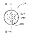
도 2a는 도 1a 및 1b의 컷팅 공구 홀더의 헤드 부분의 저면도이다.
도 2b는 도 2a의 헤드 부분의 사시도이다.
도 2c는 도 2a 및 2b의 헤드 부분의 측면도이다.
도 2d는 도 2a 및 2c의 헤드 부분의 다른 사시도이다.
도 3a는 도 1a 및 1b의 컷팅 공구 홀더의 본체 부분의 측면도이다.
도 3b는 도 3a의 본체 부분의 측면도이다.
도 3c는 도 3b의 도면으로부터 90°회전된, 도 3a 및 3b의 본체 부분의 다른 측면도이다.
도 3d는 본체 부분의 평면도이다.
도 4a는, 확대되고 그리고 부분들이 설명을 위해서 비례를 벗어나 도시된, 도 3a 내지 3d의 본체 부분의 캠 개구부의 부분적인 개략적 측면도이다.
도 4b는 도 1a 및 1b의 컷팅 공구 홀더의 캠 샤프트와 함께 도 4a의 캠 개구부를, 삽입된 상태로 도시한, 부분적인 개략적 측면도이다.
도 4c는 다른 캠 개구부와 함께 상기 캠 개구부 내에 삽입된 컷팅 공구 홀더를 도시한 개략적인 측면도이다.
도 5a는 도 1a 및 1b의 컷팅 공구 홀더의 캠 샤프트의 측면도이다.
도 5b는 도 5a의 캠 샤프트의 측면도이다.
도 5c는 도 5b의 도면으로부터 90°회전된, 도 5a 및 5b의 캠 샤프트의 측면도이다.
도 5d는 도 5a 내지 5c의 캠 샤프트의 후면도이다.
도 5e는 도 5d의 선 5E-5E를 따라서 취한 횡단면도이다.
도 5f는 도 5c의 선 5F-5F를 따라서 취한 횡단면도이다.
도 6a는 도 1a 및 1b의 컷팅 공구 홀더의 종동부의 측면도이다.
도 6b는 도 6a의 종동부의 측면도이다.
도 6c는 도 6b의 도면으로부터 90°회전된, 도 6a 및 6b의 종동부의 측면도이다.
도 6d는 도 6a 내지 6c의 종동부의 평면도이다.
도 7a는 도 1a 및 1b의 컷팅 공구 홀더를, 탈착된 위치에서 도시한, 횡단면적 측면도이다.
도 7b는 도 7a의 컷팅 공구 홀더를, 부착된-언록킹된 위치에서 도시한, 횡단면적 측면도이다.
도 7c는 도 7a 및 7b의 컷팅 공구 홀더를, 부착된-록킹된 위치에서 도시한, 횡단면적 측면도이다.
도 7d는 도 7a 내지 7c의 컷팅 공구 홀더를, 클램핑된 위치에서 도시한, 횡단면적 측면도이다.
도 8a는 다른 종동부의 측면 사시도이다.
도 8b는 도 8a의 종동부의 측면도이다.
도 8c는 도 8b의 도면으로부터 90°회전된, 도 8a 및 8b의 종동부의 측면도이다.
도 8d는 도 8a 내지 8c의 종동부의 평면도이다.
도 9a는 도 8a 내지 8d의 종동부를 위해 구성된 헤드 부분의 측면도이다.
도 9b는 도 9a의 헤드 부분의 저면도이다. BRIEF DESCRIPTION OF THE DRAWINGS For a better understanding of the claimed subject matter and to show how the disclosure may be carried into effect, reference will now be made to the accompanying drawings.
1A is a perspective view of a cutting tool holder in a clamped state.
1B is an exploded view of a portion of the cutting tool holder of FIG. 1A.
Figure 2a is a bottom view of the head portion of the cutting tool holder of Figures 1a and 1b.
2B is a perspective view of the head portion of FIG. 2A.
Figure 2C is a side view of the head portion of Figures 2A and 2B.
Figure 2d is another perspective view of the head portion of Figures 2a and 2c.
Figure 3a is a side view of the body portion of the cutting tool holder of Figures 1a and 1b.
Figure 3b is a side view of the body portion of Figure 3a.
Figure 3c is another side view of the body portion of Figures 3a and 3b, rotated 90 ° from the view of Figure 3b.
FIG. 3D is a plan view of the main body portion.
4A is a partial schematic side view of the cam opening of the body portion of Figs. 3A-3D, enlarged and shown in proportions for illustration purposes.
Fig. 4b is a partial schematic side view, with the cam opening of Fig. 4a inserted, with the camshaft of the cutting tool holder of Figs. 1a and 1b.
4C is a schematic side view showing a cutting tool holder inserted in the cam opening with another cam opening.
Figure 5a is a side view of the camshaft of the cutting tool holder of Figures 1a and 1b.
Fig. 5B is a side view of the camshaft of Fig. 5A. Fig.
5C is a side view of the camshaft of Figs. 5A and 5B, rotated 90 DEG from the view of Fig. 5B.
5D is a rear view of the camshaft of Figs. 5A to 5C. Fig.
5E is a cross-sectional view taken along
Figure 5f is a cross-sectional view taken along
Fig. 6A is a side view of the follower of the cutting tool holder of Figs. 1A and 1B.
6B is a side view of the follower of FIG. 6A.
6C is a side view of the follower of Figs. 6A and 6B, rotated 90 DEG from the view of Fig. 6B.
6D is a plan view of the follower of Figs. 6A to 6C.
Figure 7a is a cross-sectional side view of the cutting tool holder of Figures 1a and 1b in the detached position.
Figure 7b is a cross-sectional side view of the cutting tool holder of Figure 7a in an attached-unlocked position.
7C is a cross-sectional side view of the cutting tool holder of Figs. 7A and 7B in an attached-locked position; Fig.
Figure 7d is a cross sectional side view of the cutting tool holder of Figures 7a to 7c in the clamped position.
8A is a side perspective view of another follower.
8B is a side view of the follower of FIG. 8A.
8C is a side view of the follower of Figs. 8A and 8B, rotated 90 DEG from the view of Fig. 8B.
FIG. 8D is a plan view of the follower of FIGS. 8A-8C. FIG.
Figure 9A is a side view of the head portion configured for the follower of Figures 8A-8D.
Fig. 9B is a bottom view of the head portion of Fig. 9A. Fig.
이하의 설명에서, 본원의 청구 대상의 여러 가지 양태들이 설명될 것이다. 설명의 목적을 위해서, 특정 구성 및 상세 내용이 충분히 구체적으로 기술되어 본원의 청구 대상의 완전한 이해를 제공한다. 그러나, 본원의 청구 대상이 여기에서 제시된 구체적인 상세 내용이 없이도 실행될 수 있다는 것이 또한 당업자에게 자명할 것이다. In the following description, various aspects of the claimed subject matter will be described. For purposes of explanation, specific configurations and details are set forth in sufficient detail to provide a thorough understanding of the claimed subject matter. However, it will also be apparent to one skilled in the art that the subject matter of the present application may be practiced without the specific details presented here.
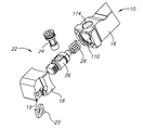
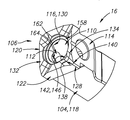
이제, 중심을 통해서 길이방향으로 연장하는 길이방향 축(AL1)을 가지고, 그리고 상기 길이방향 축(AL1)과 평행하게 연장하는 전방 및 후방 방향(DF, DR)을 규정하는 전방 및 후방 단부(12, 14)를 포함하는 세장형의 모듈형 컷팅 공구 홀더(10)를 도시한 도 1a를 참조한다. Now, with the longitudinal axis (A L1) extending longitudinally through the center, and a front defining a front and rear direction (D F, D R) extending parallel to said longitudinal axis (A L1) and Reference is made to Fig. 1A, which shows a modular
컷팅 공구 홀더(10)가 회전식 컷팅 공구 홀더일 수 있다. 컷팅 공구 홀더(10)가 본체 부분(16) 및 헤드 부분(18)을 포함한다. The
헤드 부분(18)이 컷팅 요소(20)를 포함할 수 있다. 헤드 부분(18)이 하나의 컷팅 요소(20)만을 또는 복수의 컷팅 요소(20)를 홀딩하도록 구성될 수 있다. 각각의 컷팅 요소(20)가 컷팅 삽입체일 수 있다. 헤드 부분(18)이 컷팅 요소(20)를 홀딩하기 위한 포켓(19)으로 형성될 수 있다. The
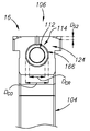
이제 도 1b를 또한 참조하면, 헤드 부분(18)이 클램핑 메커니즘(22)을 통해서 본체 부분(16)에 고정될 수 있다. 1B, the
클램핑 메커니즘(22)은 캠 샤프트(24) 및 종동부(26)를 포함한다. 클램핑 메커니즘(22)이 또한 편향 부재(28)를 포함할 수 있고, 이러한 비-제한적인 예에서 상기 편향 부재(28)가 스프링이다. 클램핑 메커니즘에 속하는 것으로 간주되는 요소는, 헤드 부분이 클램핑된 위치 또는 언클램핑된 위치로 이동하게 유도하는 것이다.The
클램핑 메커니즘(22)은, 결합을 통해서 길이방향 축(AL1)을 따른 종동부(26)의 선형 운동을 유발하는 캠 샤프트(24)의 회전을 통해서, 언클램핑된 위치와 클램핑된 위치 사이에서 이동되도록 구성된다. 종동부(26)의 선형 운동은, 헤드 부분(18)으로 하여금 본체 부분(16)에 대해서 클램핑되게 또는 언클램핑되게 허용할 수 있다. The
클램핑 메커니즘(22)의 가능한 장점은 적은 수의 요소를 이용하는 것임을 이해할 수 있을 것이다. 이러한 예에서, 클램핑 메커니즘(22)이 단지 2개의 요소 즉, 캠 샤프트(24) 및 종동부(26)를 이용하여 본체 부분(16)에 대해서 헤드 부분(18)을 클램핑 또는 언클램핑하도록 구성될 수 있다. 제 3 요소, 즉 편향 부재(28)가 본체 부분(16)으로부터 연장된 위치에 헤드 부분(18)의 위치 변화 및/또는 헤드 부분(18)의 배치를 가속할 수 있을 것이고, 이는 헤드 부분(18)의 용이한 제거를 보조할 수 있을 것이나, 클램핑 메커니즘(22)의 동작에 필수적인 것은 아니다. 일부 바람직한 실시예에서, 편향 부재(28)가, 예시적으로 도시된 압축 스프링에 대한 대안으로서, 비틀림 스프링(미도시)일 수 있고, 이는 유리한 위치결정(locating) 기능을 제공할 수 있다(즉, 헤드 부분을 본체 부분에 고정할 때, 상기 스프링이 부분의 배치를 보조할 수 있다). 편향 부재(28)를 포함할 때, 클램핑 메커니즘(22)이 단지 3개의 요소(또는 편향 부재를 그 일 단부에서 홀딩하기 위한 앵커링(anchoring) 부재가 필요한 경우에 4개의 요소)를 이용하여 본체 부분(16)에 대해서 헤드 부분(18)을 클램핑 또는 언클램핑하도록 구성될 수 있다.It will be appreciated that a possible advantage of the
도 2a 내지 2d를 참조하여, 헤드 부분(18)을 보다 구체적으로 설명할 것이다. Referring to Figures 2a-2d, the
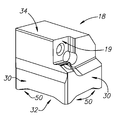
헤드 부분(18)은 결합 면(32)과 대향된 상단부 면(34) 사이에서 연장하는 둘레 표면(30)을 포함할 수 있다. 포켓(19)이 둘레 표면(30)과 상단부 면(34)의 삽입부에 형성될 수 있다. 헤드 부분(18)은 상기 결합 면(32)으로부터 내부에서 연장하는 록킹 보어(36)로 형성될 수 있다. 헤드 부분 축(AH)(도 2c)이 헤드 부분(18)을 통해서 그리고 록킹 보어(36)와 동축으로 연장할 수 있다. The
둘레 표면(30)이 복수의, 예를 들어, 4개의 하위(sub)-표면(38, 40, 42, 44)을 포함할 수 있다. 그러나, 그 대신에, 둘레 표면(30)이 원통형일 수 있고, 그러한 경우에 단지 하나의 연속적인 표면이 존재할 것임을 이해할 수 있을 것이다. 대안적으로, 필요에 따라서, 둘레 표면(30)이 상이한 형상이 될 수 있고 그리고 상응하는 수의 하위-표면을 가질 수 있을 것이다. 인접한 하위-표면(38, 40, 42, 44)의 각각의 쌍이 공통 엣지(46)에서 만날 수 있다. 공통 엣지(46)의 하나 이상이 결합 면(32)으로부터 상단부 면(34)까지 연장할 수 있다. The
결합 면(32)이 베이스 표면(48) 및 상호록킹 요소(50)를 포함할 수 있다. 상호록킹 요소(50)가 정확하게 4개의 상호록킹 요소일 수 있고, 그러한 상호록킹 요소의 각각이 외측으로 돌출하는 돌출부(50)의 형태가 된다. 도시된 실시예에서와 같이, 상호록킹 요소(50)가 동일한 형상을 가질 수 있다.The
베이스 표면(48)이 평면형일 수 있다. 베이스 표면(48)이 돌출부(50) 중 하나와 록킹 보어(36) 사이에 배치된 링-형상의 내측 부분(52)을 가질 수 있다. 베이스 표면(48)은 복수의 내측 부분(53)을 가질 수 있고, 각각의 내측 부분(53)이 상기 돌출부(50) 중 하나와 록킹 보어(36) 사이에 배치된다. 베이스 표면(48)이 인접한 돌출부들(50) 사이에 배치된 외측 부분(54)을 가질 수 있다. 베이스 표면(48)이 복수의 외측 부분(54)을 포함할 수 있고, 상기 외측 부분(54)의 각각이 인접한 돌출부들(50)의 상이한 쌍 사이에 배치된다.The
돌출부(50)가 결합 면(32)의 둘레에 위치될 수 있다. 달리 설명하면, 각각의 돌출부(50)가 둘레 표면(30)과 결합 면(32)의 삽입부(58)에 위치된 제 1 단부(56)를 가질 수 있고, 그리고 제 1 단부(56)로부터 상기 결합 면(32)을 따라서 배치되고 상기 둘레 표면(30)으로부터 이격된 제 2 단부(60)까지 연장할 수 있다. 둘레 표면(30)이 인접한 하위-표면(38, 40, 42, 44), 즉 공통 엣지(46)에서 만나는 인접한 쌍들을 포함하는 실시예에서, 돌출부의 제 1 단부(56)가 공통 엣지(46)에서 둘레 표면(30) 및 결합 면(32)의 삽입부에 위치될 수 있다. 삽입부는 또한 공통 엣지(46)에 인접한 둘레 표면(30)의 부분까지 연장할 수 있다. 도시된 비제한적인 예에서, 결합 면(32)과 공통 엣지(46)의 교차부가 중심점(62)으로부터 결합 면(32)의 가장 원위의(distal) 부분을 구성한다. 이러한 예에서, 결합 면(32)의 중심점(62)이 또한 록킹 보어(36)의 중심점이 된다. 돌출부(50)의 각각이, 상기 중심점(62)에 대해서 원위적인 결합 면(32)의 부분들에 배치될 수 있다. 내측 부분(52)이 제 2 단부(60)와 록킹 보어(36) 사이에 배치될 수 있는 것으로서 추가적으로 규정될 수 있다. The
둘레 표면(30)에서의 각각의 돌출부의 제 1 단부(56)의 최외측 표면 또는 표면들(64)이 평면적일 수 있다. 각각의 돌출부의 제 2 단부(60)의 최외측 표면(66)이 오목할 수 있다. The outermost surfaces or
각각의 돌출부(50)가 상기 베이스 표면(48)으로부터 이격되고 2개의 대향하는 엣지(70, 72)를 가지는 비-접촉 표면(68), 및 상기 비-접촉 표면(68)의 각각의 엣지(70, 72)로부터 상기 베이스 표면(48)까지 각각 연장하는 2개의 접촉지지(abutment) 표면(74, 76)을 포함하고, 상기 비-접촉 표면(68)이 상기 2개의 대향하는 엣지들(70, 72) 사이에서 연장한다. Each
비-접촉 표면(68)이 평면형일 수 있다. 각각의 비-접촉 표면(68)이 다른 비-접촉 표면(68)과 공통 평면적일 수 있다. 각각의 비-접촉 표면(68)이 베이스 표면(48)과 공통 평면적일 수 있다. 각각의 비-접촉 표면(68)이 상기 베이스 표면(48)으로부터 공통(common) 크기의 거리(DS1)(도 2c)로 이격될 수 있다.The
접촉지지 표면(74, 76)이 평면형일 수 있다. 접촉지지 표면(74, 76)이 베이스 표면(48) 및/또는 비-접촉 표면(68)에 대해서 경사질 수 있다. 각각의 돌출부(50)의 접촉지지 표면(74, 76)이 비-접촉 표면(68)에 대해서 서로 거울 이미지가 될 수 있다. 달리 설명하면, 각각의 돌출부(50)의 접촉지지 표면(74, 76)이 베이스 표면(48) 및/또는 비-접촉 표면(68)에 대해서 동일하게 경사질 수 있고, 하나의 접촉지지 표면(74, 76)이 양의(positive) 경사를 가지고 다른 접촉지지 표면이 음의 경사를 가진다. The contact support surfaces 74,76 may be planar. The contact support surfaces 74 and 76 may be inclined relative to the
달리 설명하면, 돌출부(50)가 각각 테이퍼형 형상을 가질 수 있다. In other words, each of the
록킹 보어(36)가 결합 면(32)에서의 보어 엣지(78), 상기 보어 엣지(78)로부터 헤드 부분(18) 내로 내측으로 연장하는 보어 내부 표면(80), 및 상기 결합 면(32)으로부터 원위적인 보어 단부 표면(82)을 포함할 수 있다. A locking bore 36 is defined by a
보어 엣지(78)가 대향하는 제 1 및 제 2의 하위-엣지(84, 86) 및 상기 제 1 및 제 2 하위-엣지 사이에서 연장하는 제 3 및 제 4 하위-엣지(88, 90)를 가질 수 있다. 각각의 하위-엣지(84, 86, 88, 90)가 오목한 형상을 가질 수 있다.
보어 엣지(78)가 세장형 형상을 가진다. 세장형부가 제 1 및 제 2 하위-엣지들(84, 86) 사이에 위치될 수 있다. 달리 설명하면, 제 1 및 제 2 하위-엣지들(84, 86) 사이의 거리의 크기가 제 3 및 제 4 하위-엣지들(88, 90) 사이의 거리의 크기 보다 클 수 있다. The
보어 엣지(78)와 단부 표면(82) 사이에서 연장하는 보어 내부 표면(80)의 각각의 부분이 보어 엣지(78)의 인접한 하위-엣지의 형상에 상응하는 형상을 가질 수 있다. 따라서, 보어 내부 표면(80)이 제 1, 제 2, 제 3 및 제 4 하위-표면(92, 94, 96, 98)을 가질 수 있고, 상기 각각의 하위-표면이 오목한 형상을 가질 수 있고 그리고 서로 반대되는 2개의 하위-표면들(92, 94) 사이에서 세장형일 수 있다.Each portion of the bore
제 3 및 제 4 하위-표면(96, 98)의 각각이 적어도 하나의 홈(100)으로 형성될 수 있다. 각각의 홈(100)이 벽 부분(102)에 의해서 분리될 수 있다. 제 3 및 제 4 하위-표면(96, 98)의 각각이 복수의 홈(100)으로 형성될 수 있다. 결과적으로, 제 3 및 제 4 하위-표면(96, 98)이 홈형의 하위-표면으로 간주될 수 있다. 제 3 및 제 4 하위-표면들(96, 98)의 각각에서의 홈이 둘 이상의 홈을 포함하는 홈들의 세트로 형성될 수 있다. 제 3 및 제 4 하위-표면(96, 98) 중 하나 또는 양자 모두가 정확하게 3개의 홈(100)으로 형성될 수 있다. 각각의 홈이 곡선형 형상을 가질 수 있다. 세트 내에서, 복수의 홈(100)의 각각이 서로 평행할 수 있다. 또한, 세트 내에서, 복수의 홈(100)의 각각이 종동부 축(AF)에 대해서 축방향으로 이격될 수 있다. 도시된 비제한적인 실시예에서, 정확하게 2개의 하위-표면 즉, 복수의 홈(100)으로 형성된 제 3 및 제 4 하위-표면(96, 98)이 존재한다. Each of the third and fourth
제 1 및 제 2 하위-표면(92, 94)의 각각이 벽 부분(102) 보다 더 중심점(62)으로부터 이격될 수 있다. 그러한 이격은, 이하에서 명확하게 설명하는 바와 같이, 록킹 보어(36) 내로의 종동부(26)의 삽입을 허용할 수 있다. 제 1 및 제 2 하위-표면(92, 94)의 각각이 홈(100)으로 형성된 하위-표면들(96, 98) 사이에 배치될 수 있고 또는 하위-표면들(96, 98)을 분리할 수 있다. 제 1 및 제 2 하위-표면(92, 94)의 각각이 방사상 내측으로 돌출하는 벽 부분 즉, 예를 들어 벽 부분(102)을 가지지 않을 수 있다. 제 1 및 제 2 하위-표면(92, 94)이 비-홈형 하위-표면으로 간주될 수 있다. 비-홈형 하위-표면(92, 94)이 제 3 및 제 4 하위-표면들(96, 98)을 분리할 수 있다. Each of the first and second
도 3a 내지 3d를 참조하여, 본체 부분(16)을 보다 구체적으로 설명할 것이다. Referring to Figures 3a-3d, the
일부 실시예에서, 본체 부분(16)이 헤드 부분(18)을 제조하는 재료 보다 더 큰 경직성(stiffness)을 가지는 재료로 제조될 수 있다. 예를 들어, 본체 부분(16)이 텅스텐 탄화물로 제조될 수 있고 그리고 헤드 부분(18)이 스틸로 제조될 수 있다. 본체 부분(16)이 전방 결합 면(106)과 대향하는 후방 단부 면(108)(도 1a) 사이에서 연장하는 둘레 벽(104)을 포함할 수 있다. 본체 부분(16)이 전방 결합 면(106)으로부터 내부에서 연장하는 본체 부분 보어(110), 캠 리세스(112) 및 캠 개구부(114)로 형성된다. In some embodiments, the
둘레 벽(104)이 대향하는 내부 및 외부 표면(116, 118)을 가질 수 있다. The
외측 표면(118)이 복수의, 예를 들어, 4개의 하위-표면(120, 122, 124, 126)을 포함할 수 있다. 그러나, 둘레 벽(104)이 또한 원통형일 수 있고, 그러한 경우에 단지 하나의 연속적인 표면이 존재할 수 있고, 또는 상이한 형상 및 결과적으로 상응하는 수의 하위-표면을 가질 수 있다. 인접한 하위-표면(120, 122, 124, 126)의 쌍이 공통 엣지(128)에서 만날 수 있다. 하나 이상의 공통 엣지(128)가 전방 결합 면(106)으로부터 후방 단부 면(108)까지 연장할 수 있다. The outer surface 118 may include a plurality of, for example, four
내부 표면(116)이 복수의 하위-표면을 포함할 수 있고, 하나의 하위-표면(130)(도 3a)을 제외하고, 도시되어 있지 않다. 내부 표면(116)이 정확하게 4개의 하위-표면을 포함할 수 있다. 각각의 내부 하위-표면이 대향하는 외부 하위-표면과 평행하게 연장할 수 있다. 그 대신에, 내부 표면(116)이 원통형일 수 있다. The inner surface 116 may include a plurality of sub-surfaces and is not shown, except for one sub-surface 130 (FIG. 3A). The inner surface 116 may comprise exactly four sub-surfaces. Each inner sub-surface can extend parallel to the opposite outer sub-surface. Alternatively, the inner surface 116 may be cylindrical.
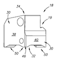
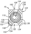
전방 결합 면(106)이 베이스 표면(132) 및 상호록킹 요소(134)를 포함할 수 있다. 상호록킹 요소(134)가, 각각 리세스(134) 형태의, 정확하게 4개의 상호록킹 요소일 수 있다. 상호록킹 요소(134)가, 도시된 실시예에서와 같이, 동일한 형상을 가질 수 있다. The
베이스 표면(132)이 평면형일 수 있다. 베이스 표면(132)이 리세스(134) 중 하나와 인접한 리세스(134) 사이에 배치된 외측 부분(136)을 가질 수 있다. 인접한 리세스들(134)의 각각의 쌍 사이에 배치된 외측 부분(136)이 존재할 수 있다.The
리세스(134)가 전방 결합 면(106)의 둘레에 위치될 수 있다. 달리 설명하면, 그리고 도 3a만에 대해서 간단히 언급하면, 각각의 리세스(134)가 둘레 벽(104)과 전방 결합 면(106)의 교차부(140)에서의 제 1 단부(138)로부터, 상기 전방 결합 면(106)을 따라서 배치되고 상기 둘레 벽(104)으로부터 이격된 제 2 단부(142)까지 방사상 내측 방향으로 연장할 수 있다. 둘레 벽(104)이 인접한 하위-표면(120, 122, 124, 126)을 포함하고, 인접한 쌍들이 공통 엣지(128)에서 만나는 실시예에서, 리세스의 제 1 단부(138)가 결합 면(32)과 공통 엣지(128)에서의 둘레 벽(104)의 교차부에 위치될 수 있다. 상기 교차부는 또한 상기 공통 엣지(128)에서의 둘레 벽(104)의 부분들까지 연장할 수 있다. 도시된 비제한적인 예에서, 전방 결합 면(106)과 공통 엣지(128)의 교차부가, 상기 전방 결합 면(106)의 중심점(144)으로부터 가장 원위적인 전방 결합 면(106)의 부분이다. The
이러한 예에서, 상기 전방 결합 면(106)의 중심점(144)은 또한 본체 부분 보어(110)의 중심점이다. 각각의 리세스(134)가, 그 중심점(144)에 대해서 원위적인 전방 결합 면(106)의 부분에 배치될 수 있다. In this example, the
각각의 리세스(134)의 제 2 단부(142)의 최외측 표면(146)이 오목형일 수 있다. The outermost surface 146 of the second end 142 of each
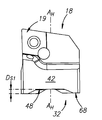
도 3d를 참조하면, 각각의 리세스(134)가 상기 베이스 표면(132)으로부터 이격되고 2개의 대향 엣지(150, 152)를 가지는 비-접촉 표면(148), 및 상기 비-접촉 표면(148)의 각각의 엣지(150, 152)로부터 상기 베이스 표면(132)까지 연장하는 2개의 접촉지지 표면(154, 156)을 포함하고, 상기 비-접촉 표면(148)은 상기 2개의 대향 엣지들(150, 152) 사이에서 연장한다. Referring to FIG. 3D, each of the
상기 비-접촉 표면(148)이 평면형일 수 있다. 각각의 비-접촉 표면(148)이 서로 동일 평면적일 수 있다. 각각의 비-접촉 표면(148)이 상기 베이스 표면(132)에 대해서 평행할 수 있다. 각각의 비-접촉 표면(148)이 베이스 표면(132)으로부터 동일한 크기의 거리(DS2)(도 3b)로 이격될 수 있다.The
접촉지지 표면(154, 156)이 베이스 표면(132) 및/또는 비-접촉 표면(148)에 대해서 경사질 수 있다. 접촉지지 표면(154, 156)이 평면형일 수 있다. 주어진 리세스(134)의 접촉지지 표면(154, 156)이 비-접촉 표면(148)에 대해서 서로 거울 이미지가 될 수 있다. 달리 설명하면, 각각의 리세스(134)의 접촉지지 표면(154, 156)이 베이스 표면(132) 및/또는 비-접촉 표면(148)에 대해서 동일하게 경사질 수 있고, 접촉지지 표면(154, 156) 중 하나가 양의 경사를 가지고 그리고 다른 하나가 음의 경사를 가진다.The contact support surfaces 154 and 156 may be inclined relative to the
달리 설명하면, 리세스(134)가 각각 테이퍼형 형상을 가질 수 있다. In other words, each of the
본체 부분(16)의 접촉지지 표면(154, 156)이 헤드 부분(18)의 접촉지지 표면(74, 76)과 상호록킹되도록 구성된다. The contact support surfaces 154 and 156 of the
도 3a에 가장 잘 도시된 바와 같이, 본체 부분 보어(110)가 전방 결합 면(106)에서의 보어 엣지(158), 내부 표면(116) 및 단부 표면(160)(도 3d) 사이에 형성될 수 있다. 3A, a body portion bore 110 is formed between the
보어 엣지(158)가 원형일 수 있다. The
캠 리세스(112)(도 3a)가 내부 하위-표면(130) 내에 형성될 수 있고, 그리고 상기 본체 부분 보어(110)로부터 둘레 벽(104)의 일부인 단부 벽 부분(164)까지 연장하는 둘레 표면(162)을 가질 수 있다. The cam recess 112 (Figure 3A) can be formed in the inner sub-surface 130 and the
이제 도 3b를 참조하면, 캠 리세스(112)가 캠 개구부(114)와 동축적일 수 있다. 캠 리세스(112)가, 내부에서 내접될(inscribe) 수 있는 가장 큰 가능한 원의 직경인, 캠 개구부(114)의 직경(DCO) 보다 작은, 내부에서 내접될 수 있는 가장 큰 가능한 원의 직경인, 직경(DCR)을 가질 수 있다. Referring now to FIG. 3B, the
캠 개구부(114)가 연속적인 엣지(166)를 가지는 개구의 형태일 수 있다. 연속적인 엣지(166)를 가지는 캠 개구부(114)의 가능한 장점은, 그러한 캠 개구부(114)가 보강된 구조를 제공하는 재료에 의해서 둘러싸일 수 있다는 것이다. 특히, 캠 개구부(114)가 비-원형이다. The
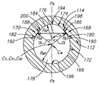
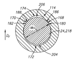
이제 도 4a를 참조하면, 비-원형 캠 개구부(114)의 추가적인 특징이 정면도(또는 본체 부분(16)의 측면도)에 도시되어 있다. 추가적인 특징이 캠 개구부(114)에 대해서 설명되어 있지만, 그러한 특징이 임의의 클램핑 메커니즘 개구부에 적용될 수 있다. 예를 들어, 캠 리세스(112)가 캠 개구부(114) 또는 도 4c에 도시된 대안적인 캠 개구부(114')에 대해서 후술되는 특징 중 임의의 특징을 가질 수 있다. Referring now to FIG. 4A, additional features of
캠 개구부(114)는, 평면도에서, 2개의 이격된 안착 영역(168, 170), 주요 둘레 엣지(172) 및, 이러한 비제한적인 예에서, 부가적인 둘레 엣지(174)에 의해서 형성될 수 있다. 2개의 이격된 안착 영역들(168, 170)은, 캠 개구부(114) 내의 구속부(constriction)(176)를 그들 사이에 형성한다(구속부가 도 4a에서 양-방향 화살표로 표시되어 있다). 주요 둘레 엣지(172)는 구속부(176)의 제 1 측부(178) 상에 형성되고 그리고 2개의 대향하는 주요 엣지 단부(180, 182)를 가진다. 각각의 주요 엣지 단부(180, 182)가 안착 영역(168, 170) 중의 상응하는 하나의 안착 영역에 인접할 수 있다. 부가적인 둘레 엣지(174)가, 주요 둘레 엣지(172)로부터 대향하여, 안착 영역(168, 170) 및 구속부(176)의 제 2 측부(184) 상에 형성될 수 있다. 구속부(176)의 제 2 측부(184)가 그 제 1 측부(178)로부터 구분된다. 부가적인 둘레 엣지(174)가 2개의 부가적인 엣지 단부들(186, 188) 사이에서 연장할 수 있고, 각각의 부가적인 엣지 단부가, 이러한 비제한적인 예에서, 안착 영역(168, 170) 중의 상응하는 하나에 인접한다. 캠 개구부(114)의 수직 연장 가상 평면(PR)이 2개의 이격된 안착 영역들(168, 170) 사이를 통과하고 그리고 구속부(176)의 양 측부 상에서 연장할 수 있다. The
주요 둘레 엣지(172)가 오목한 형상을 가질 수 있다. 주요 둘레 엣지(172)는, 내부에서 내접할 수 있는 최대의 가능한 원형 원호의 주요 중심점(CM)으로부터 측정된 반경(RMP)의 크기를 가질 수 있다. 주요 둘레 엣지(172)가 각각의 엣지 단부(180, 182)에 직접 인접하는 지점(190, 192)을 포함한다. The
주요 둘레 엣지(172)의 "내접할 수 있는 가장 큰 가능한 원형 원호"는 도 4b에 도시된 캠 샤프트(24)의 반경 크기보다 큰 반경 크기를 가지는 원형 원호에 상응한다는 것을 이해할 수 있을 것이다. 또한, 이러한 설명은 본원의 청구 대상에 따른 다른 주요 둘레 엣지에도 그리고 안착 영역 및 부가적인 둘레 엣지와 관련하여 설명되는 내접된 원 및 내접된 원형 원호에도 적용된다. It will be appreciated that "the largest possible circular arc " of the
안착 영역(168, 170)이, 도시된 평면도에서, 오목한 형상을 각각 가질 수 있다. 안착 영역(168, 170)은 반경(RS1, RS2)의 크기를 각각 가질 수 있고, 각각의 반경은, 이러한 비제한적인 예에서, 함께 위치되고 그에 의해서 내접될 수 있는 가장 큰 가능한 원의 공통 중심점(CS)을 함께 포함하는, 상응하는 중심점(CS1, CS2)으로부터 측정된다. 안착 영역들(168, 170)은 서로로부터 이격된다. 안착 영역(168, 170)은, 최상부 중심점(194)에 반대로 배치되는 최하부 중심점(196) 보다, 캠 개구부(114)의 최상부 중심점(194)에 더 근접할 수 있다. 다시 말해서, 이러한 비제한적인 예에서 공통 각도인, 각각의 안착 영역(168, 170)과 수직 연장 가상 평면(PR) 사이에 형성된 각도(α)가 예각이 될 수 있다. 평면(PR)이 전방 및 후방 방향(DF, DR)과 평행하게 연장할 수 있다. 최상부 중심점(194)과 최하부 중심점(196) 모두가 평면(PR) 내에 놓일 수 있다. The
일부 경우들에서, 주어진 안착 영역이, 개구부의 평면도에서 오목한 형상을 가지는 대신에, 라인 세그먼트를 특징으로 할 수 있는 형상을 가질 수 있을 것이다. 그러한 라인 세그먼트가 경사 또는 평균 경사 및 세그먼트 길이를 가질 수 있다. 그러한 안착 영역에 대한 중심점은, 그러한 세그먼트의 중심점에 수직인 가상 라인이 평면(PR)과 교차하는 지점으로서 규정될 수 있을 것이다. 이러한 방식에서, 중심점이, 캠 개구부(114)의 윤곽의 일부를 형성하는 비-오목형 안착 영역에 대해서 규정될 수 있을 것이다. In some cases, a given seating area may have a shape that can feature a line segment, instead of having a concave shape in the top view of the opening. Such a line segment may have an oblique or average slope and segment length. The center point for such a seating area may be defined as the point at which an imaginary line perpendicular to the center point of such a segment intersects the plane P R. In this manner, a center point may be defined for a non-recessed seating area that forms part of the contour of the
부가적인 둘레 엣지(174)가 오목한 형상을 가질 수 있다. 부가적인 둘레 엣지(174)가, 내접될 수 있는 가장 큰 가능한 원형 원호의 중심점(CP)으로부터 측정된 반경(RAP)의 크기를 가질 수 있다. 부가적인 둘레 엣지(174)가 또한, 후술되는, 각각의 엣지 단부(180, 182)에 직접 인접한 지점(198, 200)을 포함할 수 있다. The
주요 중심점(CM) 및 부가적인 중심점(CP)이 구속부(176, 176')의 제 1 및 제 2 측부(178, 184) 중 하나에 각각 위치될 수 있다. 보다 구체적으로, 이러한 예에서, 주요 둘레 엣지(172)의 중심점(CM, CS, CP), 안착 영역(168, 170) 및 부가적인 둘레 엣지(174)가 모두 평면(PR)을 따라서 서로로부터 이격될 수 있다. The main central point can be positioned at one of (C M) and an additional center point (P C), the first and second sides (178, 184) of the restricting portion (176, 176 '). More specifically, in this example, the center points (C M , C S , C P ), the
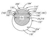
도 4b를 참조하면, 캠 샤프트(24)의 부분(218)이 캠 개구부(114) 내에 배치되고 전방 방향(DF)을 따라서 캠 개구부에 대해서 가압된 것으로 도시되어 있다.4B, a
부분(218)의 최대 치수(MC1)의 크기의 절반, 즉 그 반경의 치수가 주요 둘레 엣지(172)의 반경(RMP)의 크기 보다 작다. 그에 따라, 안착 영역(168, 170)과의 결합을 유도하는 전방 방향(DF)을 따른 힘이 인가되지 않을 때, 캠 샤프트(24)가 캠 개구부(114) 내로 삽입되고 그 내부에서 회전될 수 있도록, 주요 둘레 엣지(172)의 크기가 결정된다. 또한, 크기 차이는, 캠 샤프트(24)와 주요 둘레 엣지(172) 사이에 위치된 근위 공간(204)을 또한 형성한다. Half of the size of the largest dimension M C1 of the
안착 영역(168, 170)의 반경(RS1, RS2)의 크기가 캠 샤프트(24)의 제 1 단부(218)(도 5b)의 최대 치수(MC1)의 크기의 절반과 같을 수 있다. 안착 영역(168, 170)이 캠 샤프트(24)의 제 1 단부(218)(도 5b)의 곡률에 상응하는 곡률을 가질 수 있다. The size of the radii R S1 and R S2 of the
도시된 바와 같이, 전방 방향(DF)을 따라서 캠 샤프트(24)로 힘이 인가되고, 그리고 캠 샤프트(24)가 안착 영역(168, 170)과 결합될 때에도, 구속부(176) 및 부가적인 둘레 엣지(174)가 원위 공간(114)을 형성하도록 크기 결정되고, 그러한 크기는 캠 샤프트(24)의 내부 진입을 제한하도록, 즉 캠 샤프트(24)가 내부에 위치되지 않도록 구성된다. 달리 설명하면, 원위 공간(206) 내로의 캠 샤프트(24)의 완전한 진입이 캠 샤프트(24)와 안착 영역(168, 170)의 결합에 의해서 제한된다. 결과적으로, 캠 샤프트(24)가 최상부 중심점(194)과 접촉하는 것을 방지하도록, 구속부(176) 및 부가적인 둘레 엣지(174)의 크기가 결정된다. 달리 설명하면, 부가적인 둘레 엣지(174)와 접촉할 수 있는 범위까지 캠 샤프트(24)가 관통하여 통과하는 것을 방지하도록, 구속부(176)의 크기가 결정된다. As shown, when a force is applied to the
하나 초과의 안착 영역(168, 170)과 캠 샤프트(24)의 결합이 원위 공간(206)의 제공에 의해서 달성될 수 있다. The engagement of more than one
전술한 클램핑 특징 중 임의의 하나가, 전방 방향(DF)을 따라서 힘이 인가될 때, 캠 샤프트(24)의 회전 운동을 제한하는 것을 도울 수 있다는 것을 이해할 수 있을 것이며:It will be appreciated that any one of the aforementioned clamping features may help to limit the rotational movement of the
- 안착 영역(168, 170)의 곡률이 캠 샤프트(24)의 곡률에 상응하고;The curvature of the seating area (168, 170) corresponds to the curvature of the camshaft (24);
- 캠 샤프트(24)가 하나 초과의 안착 영역(168, 170)과 결합하고; 및The
- 안착 영역(168, 170)의 각각이, 캠 샤프트(24)의 운동이 지향되는 지점(194)으로부터 예각(α)으로 배치된다. Each of the
도 4c를 참조하면, 제공하고자 하는 리세스형 지역에 대해서, 안착 영역(168, 170)이 세장형 영역일 필요가 없으나 각각이 도시된 개구부의 평면도에서 단일 지점(168', 170')에 의해서 구성될 수 있다는 것을 이해할 수 있을 것이다. 그러한 경우에, 2개의 안착 영역(168', 170')의 중심점이, 2개의 안착 영역(168', 170')을 연결하는 가상 라인이 평면(PR)과 교차하는 곳에 위치된 공통 중심점으로 통합된다. Referring to FIG. 4C, for the recessed region to be provided, the
구체적으로, 도 4c의 대안적인 캠 개구부(114')의 비제한적인 예가, 아포스트로피(apostrophe)가 부가된 동일한 숫자로 표시된, 도 4a 및 4b의 캠 개구부(114)의 요소에 상응하는 요소를 가지고, 유일한 차이점은, 대안적인 캠 개구부(114')의 대안적인 안착 영역(168', 170')이 도시된 도면에서 단일 지점(168', 170')에 의해서 구성된다는 것이다.In particular, a non-limiting example of an alternative cam opening 114 'of Fig. 4c has an element corresponding to an element of the
대안적인 캠 개구부(114')는, 안착 영역(168', 170')을 구성하는 대안적인 2개의 엣지 단부들(180', 182') 사이에서 연장하는 주요 둘레 엣지(172')를 포함할 수 있다. 캠 개구부(114')는 또한 안착 영역(168', 170')들 사이에서 연장하고, 안착 영역(168', 170')에 결합하는 부가적인 둘레 엣지(174')를 포함할 수 있다. The alternative cam opening 114'includes a major perimeter edge 172 'extending between the alternative two edge ends 180', 182 'that make up the seating area 168', 170 ' . The cam opening 114'can also include an additional perimeter edge 174 'extending between the seating areas 168', 170 'and engaging the seating areas 168', 170 '.
도 4a 및 4b에 도시된 예가 가능한 부가적인 장점으로 인해서 바람직하지만, 특정 장점은 도 4c의 예에 의해서도 얻어질 수 있다. Although the example shown in Figures 4a and 4b is preferred due to possible additional advantages, certain advantages can also be obtained by the example of Figure 4c.
전술한 장점 중 임의 장점을 제공할 수 있는 전술한 특징 중 임의의 특징을 가지는 개구부를 구비하는 클램핑 메커니즘이 유리할 수 있다는 것을 이해할 수 있을 것이다. 그러한 특징 중 일부가 이하에서 개괄적으로 설명되어 있다. It will be appreciated that a clamping mechanism having an opening with any of the features described above, which may provide any of the advantages described above, may be advantageous. Some of those features are outlined below.
그러한 클램핑 메커니즘 개구부는, 안착 영역에 의해서 형성된 구속부(176, 176')의 일 측부 상의 2개의 영역들 사이에서 연장하는 주요 둘레 엣지, 그리고 구속부(176, 176')의 제 2의 대향하는 측부 상의 2개의 안착 영역들 사이에서 연장하는 부가적인 둘레 엣지를 구비하는 개구부로서 형성될 수 있다. Such a clamping mechanism opening has a major perimeter edge that extends between two regions on one side of the
구속부 및 부가적인 둘레 엣지는 공간을 제공하도록 크기 결정된다. 그러한 크기 결정은 공간 내로의 캠 샤프트(24)의 진입을 제한하도록 구성될 수 있다. The restricting portion and the additional peripheral edge are sized to provide space. Such sizing can be configured to limit the entry of the
안착 영역이 주요 둘레 엣지와 부가적인 둘레 엣지 사이의 영역으로서 규정될 수 있다. 지점(190, 190', 192, 192', 198, 198', 200, 200')을 포함하는 주요 둘레 엣지와 부가적인 둘레 엣지의 부분이 연관된 주요 및 부가적 엣지 단부에 그리고 또한 안착 영역에 인접하고, 그리고 안착 영역(168, 170)의 공통 중심점(CS) 또는 중심점(CS1, CS2)으로부터 이격된 중심점(CM, CP)을 가진다. The seating area can be defined as the area between the main perimeter edge and the additional perimeter edge. Adjacent to the main and additional edge ends where the major perimeter edge and the additional perimeter edge portion including the
주요 둘레 엣지 또는 부가적인 둘레 엣지 중 어느 하나를 따른 각 부분의 중심점이 안착 영역의 중심점으로부터 이격될 수 있다. The center point of each part along either the main circumferential edge or the additional circumferential edge can be spaced from the center point of the seating area.
안착 영역에 직접적으로 인접하는 주요 둘레 엣지 및 부가적인 둘레 엣지(CM, CP)의 지점의 중심점이 안착 영역(168, 170)의 공통 중심점(CS) 또는 중심점(CS1, CS2)의 대향하는 측부 상에 위치될 수 있다.The center point of the points of the main circumferential edge and the additional circumferential edges C M and C P directly adjacent to the seating area is the common center point C S or center point C S1 and C S2 of the
도 4c에 도시된 바와 같이, 캠 개구부 내의 안착 영역들 사이에서 측정된 치수(DS)의 크기가 캠 개구부 내에 수용되도록 구성되는 캠 샤프트의 단부 부분의 최대 치수(MC1) 보다 작다. 최대 치수(MC1)는 캠 샤프트의 단부 부분의 외부 직경일 수 있다. 캠 샤프트 부분이 통과하는 것을 방지하도록, 그러한 치수(DS)의 크기가 구성될 수 있다. 그러한 통과 방지는 2개의 이격된 안착 영역의 결합을 가능하게 할 수 있다. 달리 설명하면, 캠 샤프트의 부가적인 둘레 엣지와의 단일-지점 결합이 방지될 수 있다.As shown in Figure 4c, the cam is less than the largest dimension seating (M C1) of the end portion of the cam shaft is configured, the size of the dimension (D S) measured between the area to be received in the cam opening in the opening portion. The maximum dimension M C1 may be the outer diameter of the end portion of the camshaft. The size of such dimension (D S ) can be configured to prevent the camshaft portion from passing through. Such passage prevention can enable the coupling of two spaced-apart seating areas. In other words, single-point engagement with additional circumferential edges of the camshaft can be prevented.
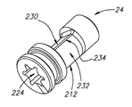
도 5a 내지 5e를 참조하여, 캠 샤프트(24)를 보다 구체적으로 설명한다. 캠 샤프트(24)가 일체형의 단일-피스 구성을 가질 수 있다. 캠 샤프트(24)가 그 중심을 통해서 연장하는 중앙 길이방향 축(AL2)을 가지는 세장형일 수 있고, 그리고 제 1 및 제 2 캠 단부(208, 210) 그리고 그로부터 연장하는 중앙 캠 부분(212)을 포함할 수 있다. 캠 샤프트(24)가 캠 샤프트(24)의 둘레를 따라서 중앙 길이방향 축(AL2)에 대해서 방사상으로 연장하는 외부 캠 표면(214)을 가질 수 있다. 캠 샤프트(24)가 제거 배열체(216)를 포함할 수 있다. 5A to 5E, the
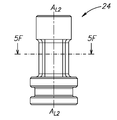
도 5b에 가장 잘 도시된 바와 같이, 중앙 길이방향 축(AL2)에 수직으로 취한, 제 1 단부(208)의 최대 치수가 MC1 로 표시되어 있다. 중앙 길이방향 축(AL2)에 수직으로 취한, 제 2 단부(210)의 최대 치수가 MC2 로 표시되어 있다. 도 5f에 가장 잘 도시된 바와 같이, 중앙 길이방향 축(AL2)에 수직으로 취한, 중앙 캠 부분(212)의 제 1 치수가 MC3 로 표시되어 있고, 그리고 중앙 길이방향 축(AL2) 및 제 1 치수(MC3) 모두에 수직으로 취한, 중앙 캠 부분(212)의 제 2 치수가 MC4 로 표시되어 있다. 제 1 치수(MC3)의 크기가 제 2 치수(MC4)의 크기 보다 작을 수 있다. As best shown in FIG. 5B, the maximum dimension of the
제 1 캠 단부(208)가 제 1 및 제 2 단부 섹션(218, 220)을 포함하는 원통형 형상을 가질 수 있고, 상기 제 1 및 제 2 단부 섹션 모두가 공통의 최대 치수(MC1) 크기, 및 그 사이에서 연장하는 중앙 섹션(222)을 가질 수 있다. The
제 1 단부(208)가 제 1 단부 섹션(218) 내로 캠 샤프트(24) 내로 연장하는 공구 수용 리세스(224)(도 5d 및 5e)로 형성될 수 있다. A
제거 배열체(216)가 공구 수용 리세스(224)에 배치될 수 있고 그리고 그로부터 연장할 수 있다. 제거 배열체(216)가 적어도 하나의 측방향으로 연장하는 앵커링 벽 부분(226)을 포함할 수 있다. 도시된 비제한적인 예에서, 제거 배열체(216)가, 적어도 하나의 측방향으로 연장하는 앵커링 벽 부분을 구성하는 스레딩(threading)(226)으로 형성되는 보어일 수 있다. 보어(216)는 중앙 길이방향 축(AL2)과 동축으로 연장할 수 있고, 그리고 제 1 캠 단부(208)로부터 중앙 캠 부분(212) 내로 연장할 수 있다. The
중앙 섹션(222)이 외부 환형 리세스(228)로 형성될 수 있다. 결과적으로, 제 3 단부 섹션(222)이 제 1 및 제 2 단부 섹션(218, 220) 모두의 외부 직경 보다 작은 외부 직경을 가질 수 있다. 외부 환형 리세스(228)가 유체-밀봉 밀봉부, 예를 들어 O-링(미도시)의 장착에 적합할 수 있다. The
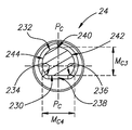
중앙 캠 부분(212)이 평면형 섹션(230) 및 곡선형 섹션(232)을 포함하고, 이들은 평면형 섹션(230)과 곡선형 섹션(232)으로 형성된 모서리(234, 236)로부터 연장한다. The
곡선형 섹션(232)은, 평면형 섹션(230)의 중앙 지점(238) 및 곡선형 섹션(232)의 중앙 지점(240)과 교차하는 양분 평면(PC)의 대향 측부 상에서 대칭적일 수 있다. 곡선형 섹션(232)의 각각의 대칭적 부분이 곡선형 하위-섹션(242, 244)을 구성할 수 있다. 각각의 곡선형 하위-섹션(242, 244)이 곡률의 변화되는 레이트(rate)를 가질 수 있다. 곡률의 변화되는 레이트는, 원형 경로를 따르는 곡률의 일정한 레이트와 구분된다. 곡률의 변화되는 레이트가 공간적인 형상을 형성할 수 있다. 공간적인 형상이 아르키메데스 나선일 수 있다. The
일부 실시예에 따라, 캠 샤프트(미도시)의 곡선형 섹션이, 도시된 바와 같이 2개의 곡선형 하위-섹션(242, 244)의 2개의 아르키메데스 나선 대신에, 예를 들어, 2개의 모서리들(234, 236) 사이에서 연장하는 하나의 아르키메데스 나선이 될 수 있다는 것을 이해할 수 있을 것이다. In accordance with some embodiments, a curved section of a camshaft (not shown) may be used instead of two Archimedes spirals of two
제 1 치수(MC3)가 평면형 섹션(230) 및 곡선형 섹션(232)의 중간 지점들(238, 240) 사이에서 측정될 수 있다. A first dimension M C3 can be measured between the
제 2 치수(MC4)가 중앙 캠 부분(212)의 최대 치수일 수 있다. 제 2 치수(MC4)가, 평면형 섹션(230)과 평행한 평면 내에 놓이는 곡선형 섹션(232)의 지점들 사이에서 측정될 수 있다. 제 2 치수(MC4)가, 상기 곡선형 섹션(232)의 중간 지점(240) 보다 평면형 섹션(230)에 더 근접하는 곡선형 섹션(232)의 지점들 사이에서 측정될 수 있다. The second dimension M C4 may be the largest dimension of the
중앙 길이방향 축(AL2)과 평행한 치수를 따라서 측정된, 평면형 섹션(230)의 길이의 크기가 LC 로서 지정된다(도 5b). The size of the length of the
제 2 캠 단부(210)가 원통형일 수 있다. 제 2 캠 단부(210)의 최대 치수(MC2)가 중앙 캠 부분(212)의 제 1 치수(MC3) 보다 클 수 있다. The
제 1 캠 단부(208)의 최대 치수(MC1)가 중앙 캠 부분(212)의 제 1 치수(MC3) 보다 클 수 있다. The maximum dimension M C1 of the first
캠 리세스(112) 내로의 삽입을 허용하도록, 제 2 캠 단부(210)의 크기가 결정될 수 있다. The size of the
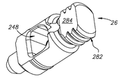
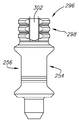
도 6a 내지 6d를 참조하여, 종동부(26)를 보다 구체적으로 설명한다. 종동부(26)가 일체형의 단일-피스 구성을 가질 수 있다. 종동부(26)가 종동부 관통-보어(248)로 형성된 종동부 본체 부분(246), 및 상기 본체 부분(246)으로부터 연장하는 종동부 헤드 부분(250)을 포함할 수 있다. 종동부(26)가, 원통형 형상을 가지고 상기 종동부 헤드 부분(250)으로부터의 대향 측부 상에서 상기 종동부 본체 부분(246)으로부터 연장하는 종동부 안착 부분(252)을 더 포함할 수 있다. With reference to Figs. 6A to 6D, the
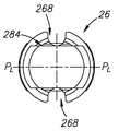
종동부(26)가 대향하는 전방 및 후방 주요 면(254, 256), 상기 주요 면에 수직으로 연장하는 제 1 및 제 2 마이너(minor) 면(258, 260), 그리고 상기 전방 및 후방 주요 면의 및 상기 제 1 및 제 2 마이너 면(254, 256, 258, 260)의 각각에 수직한 상단부 및 하단부 면(262, 264)을 구비할 수 있다. 중앙 길이방향 평면(PL)이 종동부(26)의 중심 그리고 제 1 및 제 2 마이너 면(258, 260)을 통해서 연장할 수 있고 그리고 전방 및 후방 주요 면(254, 256)에 평행할 수 있다. 길이방향 종동부 축(AF)이 종동부(26)의 중심 그리고 그 상단부 및 하단부 면(262, 264)을 통해서 연장할 수 있다. 종동부(26)가 중심 길이방향 평면(PL)의 양 측부 상에서 대칭적인 형상을 가질 수 있다. 종동부(26)가 그 상단부 및 하단부 면들(262, 264) 사이에서 세장형일 수 있다. Wherein the
종동부 본체 부분(246)이, 종동부 헤드 부분(250)에 인접하여, 길이방향 종동부 축(AF)에 대해서 횡단방향으로 연장하는 환형 립(266)을 포함할 수 있다. 환형 립(266)은 냉각제 유동 경로를 제공하도록 구성된 적어도 하나의 냉각제 리세스(268)로 형성될 수 있다. The
종동부 관통-보어(248)가 전방 및 후방 주요 면(254, 256) 사이에서 연장할 수 있고 그리고 전방 및 후방 주요 면(254, 256)에 대해서 개방될 수 있다. 종동부 관통-보어(248)는 평면형 섹션(270) 및 U-형상의 곡선형 섹션(272)을 포함할 수 있으며, 이들은 평면형 섹션(270) 및 곡선형 섹션(272)으로 형성된 모서리(274, 276)로부터 연장한다. 중앙 길이방향 평면(PL)에 수직으로 측정된, 평면형 섹션(270)의 폭의 크기가 WF 로서 표시되어 있다(도 6b). 종동부 관통-보어(248)가 불규칙적인 형상을 가질 수 있다. 예를 들어, 관통-보어가 비-원통형 형상을 가진다. Follower-
종동부 헤드 부분(250)이 원통형일 수 있다. 종동부 헤드 부분(250)이 상부 부분(278) 및 상기 상부 부분(278)과 환형 립(266) 사이에 배치된 하부 네크(neck) 부분(280)을 포함할 수 있다. The
상부 부분(278)이 복수의 리브(282)를 포함할 수 있다. 복수의 리브(282)가 상부 부분(278)의 구분되는 제 1 및 제 2 마이너 면(258, 260) 중 하나 또는 양자 모두에 형성될 수 있다. 상부 부분(278)이 그 전방 및 후방 주요 면(254, 256)에서 리브를 가지지 않을 수 있다. 달리 설명하면, 면 또는 면들(258, 260)이 복수의 리브(282)를 포함할 수 있고 그리고 리브(282)를 가지지 않는 및/또는 평면형 표면(284)을 가지는 종동부(26)의 다른 면(254, 256)에 의해서 분리될 수 있다. The
상부 부분(278)이 그 전방 및 후방 주요 면(254, 256)에서 평면형 표면(284)을 가질 수 있다. 공통 면에 존재하는 적어도 하나의 리세스(268) 및 평면형 형상의 가능한 장점은 종동부(26)의 제조를 단순화할 수 있다는 것이다. The
복수의 리브(282)의 각각이 외측으로 연장될 수 있다. 복수의 리브(282)의 각각이 길이방향 종동부 축(AF)에 대해서 횡단방향으로 연장할 수 있다. 복수의 리브(282)의 각각이 길이방향 종동부 축(AF)에 대해서 수직으로 연장할 수 있다. 복수의 리브(282)의 각각이 평평한 외측 표면(286)을 가질 수 있다. 각각의 외측 표면(286)이 길이방향 종동부 축(AF)과 평행할 수 있다. 복수의 리브(282)의 각각이 길이방향 종동부 축(AF)의 방향으로 경사지고 길이방향 종동부 축(AF)의 방향으로 편평한 외측 표면(284)의 엣지(290)로부터 연장하는 측부 표면(288)을 가질 수 있다. 달리 설명하면, 복수의 리브(282)의 각각이 그 횡단면을 따라서 테이퍼링 형상을 가질 수 있다. 복수의 리브(282)의 각각이 다른 리브(282) 모두와 평행할 수 있다. 복수의 리브(282)가 종동부 축(AF)에 대해서 축방향으로 이격된 리브(282)를 포함한다. 복수의 리브(282)가 제 1 및 제 2 마이너 면(258, 260) 중 하나 또는 양자 모두로부터 연장하는 복수의 리브를 포함한다.Each of the plurality of
이러한 비제한적인 예에서, 각각의 면(258, 260)이 정확하게 3개의 축방향으로 이격된 리브(282)로, 또는, 달리 설명하면, 리브(282)의 3개의 층으로 형성될 수 있다. 복수의 축방향으로 이격된 리브(282)를 이용하는 것이, 허용가능한 종동부 헤드 부분(250) 크기를 유지하면서, 종동부에 대해서 충분한 구조적 강도를 제공할 수 있다는 것을 발견하였다. 3-층 구성이 유리한 크기-강도 배열을 제공할 수 있는 것으로 믿어진다. In this non-limiting example, each
하부 네크 부분(280)이 유체-밀봉 밀봉부, 예를 들어, O-링(미도시)의 장착에 적합할 수 있다. The
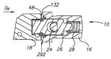
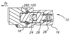
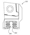
도 7a 내지 7d를 참조하면, 컷팅 공구 홀더(10)가 도시되어 있다. Referring to Figures 7a to 7d, a
도 7a에 도시된, 컷팅 공구 홀더(10)의 탈착 위치에서, 캠 샤프트(24)가 컷팅 공구 홀더(10) 내에 장착될 수 있고, 이때 제 1 캠 단부(208)가 캠 개구부(114)(도 3a) 내에 배치되고, 제 2 캠 단부(210)가 캠 리세스(112)(도 3a) 내에 배치되며, 그리고 중앙 캠 부분(212)이 종동부 관통-보어(248) 내에 배치된다. 7A, a
평면형 섹션(230)이 종동부 관통-보어(248)의 평면형 섹션(270)과 결합하도록, 중앙 캠 부분(212)이 배향될 수 있다. 그러한 결합은, 중앙 캠 부분(212)의 길이(LC)의 크기가 종동부(26)의 폭(WF)의 크기 보다 크기 때문에 가능하다. 편향 부재(28)는 그 최대 연장부일 수 있고 그리고 본체 부분(16)으로부터 돌출하도록 종동부를 편향시킬 수 있다. 캠 샤프트(24)가 공구 홀더(10)를 클램핑된 위치와 언클램핑된 위치로 이동시키기 위해서 단지 회전 운동되도록 구성된다. 본 예에서, 캠 샤프트(24)가, 단지 회전 운동만을 허용하는 배열로 본체 부분(16)에 장착된다. 결과적으로, 캠 샤프트(24)가 클램핑된 위치와 언클램핑된 위치 모두에서, 그리고 그들 사이의 임의의 전이적(transitional) 위치에서 종동부 관통-보어(248)를 통해서 연장하고, 그에 의해서 종동부(26)가 본체 부분(16)으로부터 의도하지 않게 빠져나오는 것을 방지한다. 복수의 리브(282)를 가지는, 종동부(26)의 제 1 및 제 2 마이너 면(258, 260)이 록킹 보어(176)의 편평한 제 1 및 제 2 하위-표면(92, 94)과 정렬될 수 있다. The
헤드 부분(18)이 후방 방향(DR)으로 이동될 수 있고 및/또는 본체 부분(16)이 전방 방향(DF)으로 이동될 수 있고, 그에 따라 컷팅 공구 홀더(10)를 도 7b의 부착된-언록킹된 위치로 이동시킬 수 있다. 그러한 위치에서, 헤드 부분(18)이 종동부(26)의 상단부 면(262) 상에 안착될 수 있다. The
특히, 편향 부재(28)의 편향력이, 상부에 안착될 그리고 수직 배향으로 유지될 때, 본체 부분(16) 및 헤드 부분(18)을 이격시키기에 충분하다. 그러한 간격은 본체 부분(16)의 베이스 표면(132)과 헤드 부분(18)의 베이스 표면(48) 사이에 갭(292)을 제공한다. 갭(292)이 충분히 넓어서 본체 부분(16)과 헤드 부분(18)의 접촉을 방지할 수 있고 그리고 헤드 부분(18)의 돌출부(50)와 본체 부분(16)의 베이스 표면(132) 사이에 간격을 제공할 수 있다. In particular, the biasing force of the biasing
헤드 부분(18) 또는 본체 부분(16)이 시계방향 또는 반시계 방향으로 1/4 회전으로 회전되어 컷팅 공구 홀더(10)가 도 7c의 부착된-록킹된 위치로 이동될 수 있게 한다. 편향력이 도시된 돌출된 위치에서 본체 부분(16)을 헤드 부분(18)으로부터 이격시켜 유지하기에 충분하기 때문에, 본체 부분(16)이 상부에 헤드 부분(18)이 안착된 수직 배향으로 유지될 때, 헤드 부분(18)을 회전시키기 위해서 오직 회전력만이 인가될 필요가 있다. 달리 설명하면, 상승력의 인가에 의해서 적절하게 먼저 배치될 필요가 없이, 헤드 부분(18)이 유리하게 회전될 수 있다. The
그러한 회전은 복수의 리브(282)를 헤드 부분(18)의 홈(100)과 정렬되게 할 수 있다. 복수의 리브(282)와 홈(100)의 상호록킹은 헤드 부분(18)이 본체 부분(16)에 대해서 전방 방향(DF)으로 운동하는 것을 방지할 수 있다. 그러한 상호록킹은 헤드 부분(18)이 본체 부분(16)으로부터 의도하지 않게 빠져나오는 것을 방지할 수 있다. Such rotation may cause a plurality of
이어서, 캠 샤프트(24)가 시계방향 또는 반시계 방향으로 1/4 회전으로 회전되어 컷팅 공구 홀더(10)가 도 7d의 클램핑된 위치로 이동될 수 있고, 이때 캠 샤프트(24)의 곡선형 섹션(232)이 종동부(26)의 평면형 섹션(270)을 본체 부분(16)에 대해서 후방 방향(DR)으로 이동시킨다. 달리 설명하면, 평면형 섹션(270)이 캠 샤프트(24)의 곡선형 섹션(232)과 결합하도록 구성된다. 각각의 곡선형의 하위-섹션(242, 244)이 종동부 관통-보어(248)와 결합하도록 구성되기 때문에, 캠 샤프트(24)가 시계방향 또는 반시계방향으로 회전되어 컷팅 공구 홀더(10)가 클램핑된 또는 언클램핑된 위치로 이동될 수 있게 한다. 특히, 캠 샤프트(24)의 1/4 회전시에 공구 홀더(10)가 클램핑된 또는 언클램핑된 위치로 이동될 수 있도록 허용하도록 각각의 곡선형 하위-섹션의 곡률이 구성된다. Then, the
그러한 운동은 편향 부재(28)를 압축할 수 있고, 그리고 갭(292)의 폭을 감소시킬 수 있다. 본체 부분(16)에 대한 헤드 부분(18)의 운동이 헤드 부분의 돌출부(50)의 접촉지지 표면(74, 76)과 본체 부분의 리세스(134)의 접촉지지 표면(154, 156)의 결합에 의해서 억제될 수 있다. 특히, 헤드 부분(18)과 본체 부분(16) 사이의 접촉이 접촉지지 표면(74, 76, 154, 156)을 통해서만 이루어진다. 캠 샤프트(24)와 종동부 관통-보어(248)의 결합이 종동부 관통-보어(248)의 평면형 섹션(270) 만으로 이루어진다는 것을 추가적으로 알 수 있다. 편향 부재(28)가, 클램핑된 위치 및 언클램핑된 위치 모두에서, 그리고 그 사이의 임의의 전이적인 위치에서 종동부(26) 상으로 연속적인 편향력을 인가하도록 구성될 수 있다는 것을 이해할 수 있을 것이다. 그러한 힘의 연속적인 인가는 캠 샤프트(24)가 본체 부분(16)으로부터 원치 않게 빠져나오는 것을 방지하는 것을 돕는다. Such movement can compress the biasing
바람직하게, 헤드 부분의 돌출부(50)의 접촉지지 표면(74, 76) 모두 및 본체 부분의 리세스(134)의 접촉지지 표면(154, 156) 모두가 동시에 접촉되도록, 접촉지지 표면이 구성된다. 그러한 배열은, 예를 들어, 요동(wobbling)을 방지할 수 있다. A contact support surface is preferably configured such that both the contact support surfaces 74,76 of the
헤드 부분(18)을 제거하기 위해서, 전술한 단계가 반대 순서로 실시된다. 특히, 캠 샤프트(24)가 회전하는 동안, 중앙 캠 부분(212) 및 종동형 관통-보어(248)의 상응하는 평면형 섹션(230, 270)의 신속 결합은, 편향 부재(28)가 본체 부분(16)으로부터 멀어지는 방향으로 헤드 부분(18)을 가압할 수 있게 허용하고, 그에 따라, 갭(292)으로 인해서, 바람직하지 못한 그들 사이의 결합이 없이, 헤드 부분(18)이 그 직후에 회전될 수 있다. In order to remove the
캠 샤프트(24)를 본체 부분(16)으로부터 제거하기 위해서, 후방 방향(DR)을 따라 종동부(26)로 힘이 인가될 수 있고, 그에 의해서 편향 부재(28)를 압축한다. 이어서, 외부 스레딩과 같은 측방향으로 연장하는 앵커링 부분으로 형성된 공구(미도시)가 제 1 캠 단부(208)의 제거 배열체(216) 내로 삽입될 수 있고 그리고 측방향 연장 앵커링 벽 부분(226)과 결합될 수 있고, 그리고 후속하여 캠 샤프트(24)와 함께 본체 부분(16)으로부터 후속하여 회수될 수 있다. To remove the
전술한 구성의 가능한 장점이 이하를 포함할 수 있다:Possible advantages of the foregoing arrangement may include:
- 클램핑된 위치에서의 헤드 부분(18)의 안정화를 위해서 각각의 결합 면 상에 4개의 이격된 상호록킹 요소를 제공한다(즉, 본체 부분 상에서의 헤드 부분의 흔들림(rocking) 또는 요동을 방지한다);To provide four spaced apart locking elements on each engagement surface (i.e., to prevent rocking or rocking of the head portion on the body portion) for stabilization of the
- 클램핑된 위치에서 헤드 부분(18)의 안정화를 위해서 각각의 결합 면의 둘레를 따라서 4개의 균일하게 이격된 상호록킹 요소를 제공한다;Providing four uniformly spaced interlocking elements along the periphery of each mating surface for stabilization of the
- 헤드 부분 및 본체 부분 상의 4개의 이격된 상호록킹 요소를 제공하는 것은, 이하에서 더 구체적으로 설명하는 바와 같이, 본체 부분 상의 4개까지의 상이한 위치에서 헤드 부분이 본체 부분에 클램핑되도록 허용하고; 달리 설명하면, 헤드 부분과 본체 부분의 결합 면이 4개의 상이한 위치에서 서로 클램핑 결합하도록 구성될 수 있다;Providing the head portion and the four spaced apart interlocking elements on the body portion allows the head portion to be clamped to the body portion at up to four different positions on the body portion, as will be described in more detail below; In other words, the mating surfaces of the head portion and the body portion can be configured to clamp together with each other at four different positions;
- 모듈형 컷팅 공구 홀더(10)가, 이하에서 더 구체적으로 설명하는 바와 같이, 본체 부분(16) 또는 헤드 부분(32)의 4번의 연속적인 1/4 회전을 통해서 4개의 상이한 위치가 될 수 있도록 구성될 수 있다; The modular
- 대향적으로 경사진 접촉지지 표면(74, 76, 154, 156)의 결합으로 인해서, 헤드 부분(18)이 시계방향 및 반시계방향 모두로 회전되는 것에 대해서 제한된다;Due to the engagement of the oppositely tapered contact support surfaces 74, 76, 154 and 156, the
- 결합 면(62)의 중심점으로부터 이격된, 상호록킹 요소(50, 134), 및 구체적으로 접촉지지 표면(74, 76, 154, 156)의 배치로 인한 헤드 부분(18)의 회전에 대한 저항; 달리 설명하면, 각각의 상호록킹 요소(50, 134)가 그 중심점(62)으로부터 원위적인 결합 면(32)의 부분에 배치되고, 그에 의해서 헤드 부분(10)을 본체 부분(16)에 대해서 회전시키는데 필요한 모멘트의 크기를 증가시킨다;The resistance to the rotation of the
- 부착된-언록킹된 위치로부터 부착된-록킹된 위치가 되도록 하기 위한 방향으로 헤드를 회전시킬 수 있는 능력으로 인한, 용이한 조립 및 배치의 가변성; Variation in ease of assembly and placement due to the ability to rotate the head in a direction to bring it from the attached-unlocked position to the attached-locked position;
- 캠 샤프트(24) 및 종동부(26) 모두가 본체 부분(16)에 대해서 여전히 유지되는 상태에서 클램핑된 위치 및 언클램핑된 위치 모두가 될 수 있도록 구성된 컷팅 공구 홀더(10)를 이용한 조립의 용이성;Assembly using a
- 헤드 및/또는 캠 샤프트(24)가 1/4 회전의 회전 이하를 필요로 하는 것에 기인한 조립 속도; - an assembly speed due to the fact that the head and / or
- 리세스(134)가 가능한 경직성 재료의 성분으로 형성되는 것으로 인한, 제조 용이성;Ease of manufacture due to the
- 복수 리브의 이용으로 인한 감소된 폭;- reduced width due to use of multiple ribs;
- 복수의 리브(282)의 수직 배향이, 경사진 배향을 가지는 리브 보다, 조립 중에 바람직하지 못한 재밍(jamming)을 덜 일으킨다는 것을 발견하였다; It has been found that the vertical orientation of the plurality of
- 캠 샤프트(24)를 본체 부분(16)에 장착하는 것이 2개의 대향 단부(208, 210)에서 이루어져, 클램핑의 방향으로(즉, 접선 방향으로 인가되는 힘의 부분을 가질 필요 없이, 예를 들어, 전방 및 후방 방향으로만 단일 축을 따른) 종동부(26) 상으로 힘을 인가하는 것 및/또는 캠 샤프트(24)의 회전 운동 만을 허용한다; 그리고Mounting of the
- 변화되는 곡률, 특히 곡선형의 하위-섹션(242, 244)의, 또는 연속적인 곡선(미도시)의 나선형 형상을 형성하는 것이, 클램핑 위치로부터 캠 샤프트가 의도하지 않게 반대로 회전하는 것을 방지할 수 있다.Forming the helical shape of the changing curvature, in particular of the
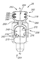
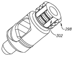
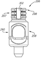
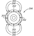
도 8a 내지 8d를 참조하면, 대안적인 종동부(296)가 도시되어 있다.8A-8D, an
대안적인 종동부(296)는 전술한 종동부(26)의 임의 특징을 가질 수 있고, 유일한 중요한 차이는, 종동부 헤드 부분(297)에서, 대안적인 복수의 외측으로 연장하는 리브(298)가 전방 및 후방 주요 면(254, 256) 및 제 1 및 제 2 마이너 면(258, 260)의 교차부(300)에 형성된다는 것이다. 종동부 헤드 부분(297)이 교차부(300) 사이에 리브를 가지지 않는다. 그에 따라, 종동부 헤드 부분(300)이, 인접한 리브(298)의 4개의 세트들 사이에서 연장하는, 리브(298)가 없는 4개의 면(302)을 가질 수 있다. The
교차부(300)가 대안적인 종동부(296)의 하위-면을 구성할 수 있다. 따라서, 도시된 비제한적인 예에서, 복수의 리브(298)로 형성된 4개의 하위 면(300), 즉 교차부가 존재한다. The
그러한 구성의 가능한 장점은, 대안적인 종동부(296)의 리브(298)와 상호록킹되도록 구성된, 하위-표면(306) 및 평면형 또는 리브가 없는 대안적인 하위-표면(308)에서 대안적인 홈(304)으로 형성된 대안적인 헤드 부분(303)(도 9a 및 9b)이, 전술한 2개의 위치 뿐만 아니라, 본체 부분 상의 4개의 상이한 위치로 배치될 수 있다는 것이 될 수 있다. 이는, 부가적인 공구 구성 가변성을 허용할 수 있다. A possible advantage of such an arrangement is that the alternative grooves 304 (not shown) in the
교차부는 대안적인 헤드 부분(118)의 하위-표면을 구성할 수 있다. 따라서, 도시된 비제한적인 예에서, 복수의 홈(304)으로 형성된, 정확히 4개의 하위-표면(306), 즉 교차부가 존재한다. The intersection may constitute a sub-surface of the alternative head portion 118. Thus, in the illustrated, non-limiting example, there are exactly four
전술한 예가 4개의 평면형 벽을 가지는 헤드 및 본체 부분에 관련된 것이지만, 만약 헤드 및 본체 부분이, 예를 들어, 원통형이라면, 필요에 따라서 상이한 수의 리브의 세트가 고려될 수 있다는 것을 이해할 수 있을 것이다. 그러한 수는, 본체 부분에 대한 헤드 부분의 상응하는 수의 위치를 허용할 수 있다. 개략적으로 설명하면, 본원의 청구 대상에 따른 종동부가, 필요에 따라, 본체 부분 상의 복수의 위치를 가질 수 있다. 또한, 일부 실시예에 따라서, 종동부 및 상응하는 헤드 부분이 하나 이상의 리브(즉, 단일 평면 내에 위치된 리브)를 위해서 구성될 수 있고, 그리고 도면에 예시된 리브의 수 및 리브의 세트를 반드시 가질 필요가 없다는 것을 이해할 수 있을 것이다. It will be appreciated that although the foregoing example relates to a head and body portion having four planar walls, it will be appreciated that if the head and body portion are, for example, cylindrical, then a different number of sets of ribs may be considered, . Such a number may allow for a corresponding number of positions of the head portion relative to the body portion. Briefly described, a follower according to the claimed subject matter can have a plurality of positions on the body portion, if desired. Also, in accordance with some embodiments, the follower and corresponding head portion can be configured for one or more ribs (i. E. Ribs positioned in a single plane), and the number of ribs and rib set It will be understood that there is no need to.
헤드 부분(18) 상에 형성하고자 하는 돌출부(50) 및 본체 부분(16) 상에 형성하고자 하는 리세스(134)에 대한 일부 실시예에서의 장점들이 존재하지만, 그러한 장점들이 존재하지 않는 다른 실시예도 존재할 수 있다는 것을 이해할 수 있을 것이다. 따라서, 전술한 임의 특징을 가지는 돌출부가 모듈형 컷팅 공구 홀더의 본체 부분 상에 형성될 수 있고, 그리고 전술한 임의 특징을 가지는 리세스가 모듈형 컷팅 공구 홀더의 헤드 부분 상에 형성될 수 있다. Although there are advantages in some embodiments for the
Claims (41)
상보적인 모듈형 컷팅 공구 홀더 부분(16, 18)의 상응하는 제 2 결합 면과 클램핑 결합하도록 구성된 제 1 결합 면(32, 106)을 포함하고;
상기 제 1 결합 면(32, 106)이:
베이스 표면(48, 132), 및
정확하게 4개의 돌출하는 돌출부(50) 또는 정확하게 4개의 리세스(134) 형태의 상호록킹 요소(50, 134)를 포함하고;
각각의 상호록킹 요소(50, 134)가:
상기 베이스 표면(48, 132)으로부터 이격되고 2개의 대향 엣지(70, 72, 150, 152)를 가지는 비-접촉 표면(68, 148)로서, 상기 비-접촉 표면이 상기 2개의 대향 엣지 사이에서 연장하는, 비-접촉 표면, 및
상기 2개의 대향 엣지(70, 72, 150, 152) 중 각각의 하나로부터 상기 베이스 표면(48, 132)까지 연장하고 그리고 상기 클램핑 결합을 위해서 구성된 2개의 접촉지지 표면(74, 76, 154, 156)을 포함하는, 모듈형 컷팅 공구 홀더 부분(16, 18).A modular cutting tool holder portion (16, 18) for a metal-working machine,
A first mating surface (32, 106) configured to clamp-mate with a corresponding second mating surface of a complementary modular cutting tool holder portion (16, 18);
Said first engagement surface (32, 106) comprising:
Base surfaces 48 and 132, and
Includes four correctly projecting protrusions (50) or interlocking elements (50, 134) in the form of exactly four recesses (134);
Each interlocking element (50, 134) comprising:
A non-contact surface (68, 148) spaced from the base surface (48, 132) and having two opposing edges (70, 72, 150, 152) Extending, non-contacting surface, and
And two contact support surfaces (74, 76, 154, 156) extending from the respective one of the two opposing edges (70, 72, 150, 152) to the base surface (48, 132) and configured for the clamping engagement (16, 18). ≪ / RTI >
상기 제 1 결합면(32)이 내부에서 연장하는 보어(36, 110)로 형성되는, 모듈형 컷팅 공구 홀더 부분(16, 18).The method according to claim 1,
Wherein the first engagement surface (32) is formed with an inwardly extending bore (36, 110).
상기 부분(18)이 컷팅 요소(20)를 홀딩하도록 구성된 헤드 부분(18)인, 모듈형 컷팅 공구 홀더 부분(16, 18).3. The method according to claim 1 or 2,
A modular cutting tool holder portion (16, 18), wherein said portion (18) is a head portion (18) configured to hold a cutting element (20).
상기 상호록킹 요소(50, 134)가 정확하게 4개의 돌출하는 돌출부(50)인, 모듈형 컷팅 공구 홀더 부분(16, 18).The method of claim 3,
The modular cutting tool holder portion (16, 18), wherein the interlocking elements (50, 134) are exactly four protruding protrusions (50).
상기 부분(16)이 상보적인 헤드 부분(18)을 홀딩하도록 구성된 본체 부분(16)이고, 상기 상보적인 헤드 부분이 다시 컷팅 요소(20)를 홀딩하도록 구성되는, 모듈형 컷팅 공구 홀더 부분(16, 18).3. The method according to claim 1 or 2,
Wherein the portion (16) is a body portion (16) configured to hold a complementary head portion (18) and the complementary head portion is configured to again hold the cutting element (20) , 18).
상기 상호록킹 요소(50, 134)가 정확하게 4개의 리세스(134)인, 모듈형 컷팅 공구 홀더 부분(16, 18).6. The method of claim 5,
Wherein the interlocking elements (50, 134) are exactly four recesses (134).
상기 상호록킹 요소(50, 134)의 각각이 상기 제 1 결합 면(32, 106)의 부분에 배치되고, 상기 부분이 그 중심점(62, 144)에 대해서 원위적인, 모듈형 컷팅 공구 홀더 부분(16, 18).7. The method according to any one of claims 1 to 6,
Characterized in that each of the interlocking locking elements (50,134) is arranged at a portion of the first mating surface (32,106) and the portion has a modular cutting tool holder portion 16, 18).
상기 상호록킹 요소(50, 134)의 각각이 테이퍼형 형상을 가지는, 모듈형 컷팅 공구 홀더 부분(16, 18).8. The method according to any one of claims 1 to 7,
A modular cutting tool holder portion (16, 18), wherein each of the interlocking elements (50, 134) has a tapered shape.
상기 접촉지지 표면(74, 76, 154, 156)의 각각이 평면형인, 모듈형 컷팅 공구 홀더 부분(16, 18).9. The method according to any one of claims 1 to 8,
A modular cutting tool holder portion (16, 18), wherein each of said contact supporting surfaces (74, 76, 154, 156) is planar.
상기 접촉지지 표면(74, 76, 154, 156)의 각각이 상기 베이스 표면(48, 132) 및/또는 비-접촉 표면(68, 148)에 대해서 경사진, 모듈형 컷팅 공구 홀더 부분(16, 18).10. The method according to any one of claims 1 to 9,
Wherein each of the contact support surfaces 74,76,154 and 156 includes a modular cutting tool holder portion 16,74 inclined relative to the base surface 48,134 and / 18).
상기 본체 및 헤드 부분(16, 18) 중 하나가 정확하게 4개의 돌출하는 돌출부(50) 형태의 상호록킹 요소(50, 134)를 포함하고, 그리고 상기 본체 및 헤드 부분(16, 18) 중 다른 하나가 정확하게 4개의 상응하는 리세스(134) 형태의 상호록킹 요소(50, 134)를 포함하며; 그리고
상기 본체 및 상기 헤드 부분(16, 18) 사이의 상기 상호록킹 요소(50, 134)의 접촉지지 표면(74, 76, 154, 156)을 통해서만 접촉이 이루어지는, 모듈형 컷팅 공구 홀더(10). 12. A device according to any one of the preceding claims, characterized in that it comprises a body part (16) according to any one of claims 1, 2 and 7 to 11 and a complementary body according to any one of claims 1, 2 and 7 to 11. A modular cutting tool holder (10) for a metal-working machine comprising a head part (18), comprising:
Characterized in that one of said body and head portions (16,18) comprises interlocking elements (50,134) in the form of exactly four protruding projections (50), and that one of said body and head portions (16,18) Includes interlocking elements (50,134) in the form of exactly four corresponding recesses (134); And
Wherein contact is made only through the contact support surfaces (74, 76, 154, 156) of the interlocking elements (50, 134) between the body and the head part (16, 18).
상기 제 1 및 상응하는 제 2 결합 면(32, 106)이 4개의 상이한 위치에서 서로 클램핑 결합하도록 구성되는, 모듈형 컷팅 공구 홀더(10).12. The method of claim 11,
Wherein the first and corresponding second mating surfaces (32, 106) are configured to clamp together with each other at four different locations.
상기 본체 부분(16) 및 상기 헤드 부분(18) 중 하나의 다른 하나에 대한 연속적인 1/4 회전을 통해서 4개의 상이한 위치 중의 각각의 위치를 취하도록 구성될 수 있는, 모듈형 컷팅 공구 홀더(10).13. The method of claim 12,
(14) that can be configured to take a respective one of four different positions through successive quarter rotations of the body portion (16) and the other one of the head portions (18) 10).
상기 헤드 부분(18)의 대향적으로 경사진 접촉지지 표면(74, 76)이 상기 본체 부분(16)의 대향적으로 경사진 각각의 접촉지지 표면(154, 156)과 접촉하여, 시계방향 및 반시계방향 모두로 상기 헤드 및 본체 부분(16, 18)이 상대적으로 회전하는 것을 방지하는, 모듈형 컷팅 공구 홀더(10).14. The method according to any one of claims 11 to 13,
The oppositely tapered contact support surfaces 74,76 of the head portion 18 contact each of the oppositely tapered contact support surfaces 154,156 of the body portion 16 such that the counter- Thereby preventing the head and body portions (16, 18) from rotating relative to each other in both counterclockwise directions.
상기 헤드 부분(18)의 모든 접촉지지 표면(74, 76, 154, 156) 및 상기 본체 부분(16)의 모든 접촉지지 표면(74, 76, 154, 156)이 동시에 접촉하도록 구성되는, 모듈형 컷팅 공구 홀더(10).15. The method according to any one of claims 11 to 14,
Is configured such that all contact support surfaces (74, 76, 154, 156) of the head portion (18) and all contact support surfaces (74, 76, 154, 156) Cutting tool holder (10).
상기 상호록킹 요소(50, 134)가 각각의 결합 면(32, 106)의 둘레를 따라서 균일하게 이격되는, 모듈형 컷팅 공구 홀더(10).16. The method according to any one of claims 11 to 15,
Wherein the interlocking elements (50,134) are uniformly spaced along the respective mating surfaces (32,106).
상기 헤드 부분 및 본체 부분이, 부착된-언록킹된 또는 부착된-록킹된 위치에서 시계방향 및 반시계방향으로, 서로에 대해서 회전하도록 구성되는, 모듈형 컷팅 공구 홀더(10).17. The method according to any one of claims 11 to 16,
Wherein the head portion and the body portion are configured to rotate with respect to each other in clockwise and counterclockwise directions in an attached-unlocked or attached-locked position.
상기 캠 샤프트(24) 및 종동부(26) 모두가 상기 본체 부분(16) 내에서 여전히 홀딩되는 상태에서, 클램핑된 위치 및 언클램핑된 위치 모두가 될 수 있도록 추가적으로 구성되는, 모듈형 컷팅 공구 홀더(10).18. The method according to any one of claims 11 to 17,
Wherein the camshaft 24 and the follower portion 26 are both still clamped and unclamped in a state in which the camshaft 24 and the follower portion 26 are still held within the body portion 16, (10).
상기 본체 부분(16)이 상기 헤드 부분(18)이 제조되는 재료 보다 더 큰 경직성을 가지는 재료로 제조되는, 모듈형 컷팅 공구 홀더(10).19. The method according to any one of claims 11 to 18,
Wherein the body portion (16) is made of a material having greater stiffness than the material from which the head portion (18) is made.
상기 모듈형 컷팅 공구 홀더(10)는 적어도 하나의 컷팅 요소(20)를 홀딩하도록 구성되고 그리고 본체 부분(16), 헤드 부분(18) 및 클램핑 메커니즘(22)을 포함하고, 상기 클램핑 메커니즘은 상기 헤드 부분(18)이 상기 본체 부분(16)에 고정되는 클램핑된 위치와 상기 헤드 부분(18)이 상기 본체 부분(16)으로부터 제거가능한 언클램핑된 위치 사이에서 이동되도록 구성되고; 상기 클램핑 메커니즘(22)은 관통-보어(248)로 형성된 종동부(26) 및 상기 종동부(26)의 관통-보어(248)를 통해서 연장하는 캠 샤프트(24)를 포함하고; 상기 캠 샤프트(24)는, 회전 운동 중에, 상기 종동부 관통-보어(248)와 결합하도록 구성된 곡선형 섹션(232)을 포함하고,
상기 결합은 종동부(26)의 선형 이동을 초래하여, 클램핑 메커니즘(22)을 클램핑 위치 또는 언클램핑 위치로 이동하게 하는 모듈형 컷팅 공구 홀더(10).A modular cutting tool holder (10) for a metal-working machine,
The modular cutting tool holder 10 is configured to hold at least one cutting element 20 and includes a body portion 16, a head portion 18 and a clamping mechanism 22, A clamped position in which a head portion (18) is secured to the body portion (16) and an unclamped position in which the head portion (18) is removable from the body portion (16); The clamping mechanism 22 includes a follower 26 formed of a through-bore 248 and a camshaft 24 extending through the through-bore 248 of the follower 26; The camshaft 24 includes a curved section 232 configured to engage the follower through-bore 248 during rotational movement,
The coupling causes a linear movement of the follower (26), causing the clamping mechanism (22) to move to a clamping position or an unclamping position.
상기 클램핑 메커니즘(22)이 2개 내지 4개의 요소를 포함하는, 모듈형 컷팅 공구 홀더(10).21. The method of claim 20,
Wherein the clamping mechanism (22) comprises two to four elements.
상기 캠 샤프트(24)가, 상기 캠 샤프트(24)의 회전 운동만을 허용하는 배열로 상기 본체 부분(16) 내에 장착되는, 모듈형 컷팅 공구 홀더(10).22. The method according to claim 20 or 21,
Wherein the camshaft (24) is mounted within the body portion (16) in an arrangement permitting only rotational movement of the camshaft (24).
상기 본체 부분(16)에 대한 상기 캠 샤프트(24)의 장착이 상기 캠 샤프트(24)의 2개의 대향 단부(208, 210)에서 이루어지는, 모듈형 컷팅 공구 홀더(10).23. The method according to any one of claims 20 to 22,
Wherein mounting of the camshaft (24) to the body portion (16) is at two opposite ends (208, 210) of the camshaft (24).
상기 캠 샤프트(24)가 클램핑된 위치 및 언클램핑된 위치 모두, 및 그 사이의 임의의 전이적인 위치에서 종동부 관통-보어(248)를 통해서 연장하도록 구성되고, 그에 의해서 상기 종동부(26)가 상기 본체 부분(16)으로부터 의도하지 않게 빠져나오는 것을 방지하는, 모듈형 컷팅 공구 홀더(10).24. The method according to any one of claims 20 to 23,
The camshaft 24 is configured to extend through the follower through-bore 248 at both the clamped and unclamped positions, and any transitional positions therebetween, whereby the follower 26, (10) from coming out of the body portion (16) unintentionally.
상기 종동부 관통-보어(248)가 상기 캠 샤프트(24)의 곡선형 섹션(232)과 결합하도록 구성된 평면형 섹션(270)을 포함하는, 모듈형 컷팅 공구 홀더(10).25. The method according to any one of claims 20 to 24,
Wherein said follower-bore (248) includes a planar section (270) configured to engage a curved section (232) of said camshaft (24).
상기 캠 샤프트(24)가 상기 종동부 관통-보어(248)의 평면형 섹션(270)과 결합하도록 구성된 평면형 섹션(230)을 더 포함하는, 모듈형 컷팅 공구 홀더(10).26. The method according to any one of claims 20 to 25,
Further comprising a planar section (230) configured to engage the planar section (270) of the follower-bore (248) of the cam shaft (24).
상기 캠 샤프트(24)의 상기 종동부 관통-보어(248)의 결합이 상기 종동부 관통-보어(248)의 평면형 섹션(270) 만으로 이루어지는, 모듈형 컷팅 공구 홀더(10).27. The method of claim 25 or 26,
Wherein the engagement of the follower through-bore (248) of the camshaft (24) comprises only a planar section (270) of the follower through-bore (248).
상기 캠 샤프트(24)의 곡선형 섹션(232)이, 바람직하게 아르키메데스 나선을 형성하는, 단일의, 그러나 변화되는, 곡률의 레이트를 가질 수 있는, 모듈형 컷팅 공구 홀더(10).28. The method according to any one of claims 20-27,
Wherein the curved section (232) of the camshaft (24) can have a single but varying rate of curvature, preferably forming an Archimedes spiral.
상기 캠 샤프트(24)의 곡선형 섹션(232)이 곡선형의 하위-섹션(242, 244)을 포함하고, 상기 각각의 하위-섹션이, 바람직하게 아르키메데스 나선을 형성하는, 변화되는 곡률의 레이트를 가지는, 모듈형 컷팅 공구 홀더(10).28. The method according to any one of claims 20-27,
Characterized in that the curved section (232) of the camshaft (24) comprises curved sub-sections (242, 244), each sub-section preferably forming an Archimedes spiral (10). ≪ / RTI >
상기 곡선형 하위-섹션(242, 244)이 대칭적이고 그리고 상기 곡선형 섹션(232)과 교차하는 양분 평면(PC)의 대향 측부들 상에 배치되는, 모듈형 컷팅 공구 홀더(10).30. The method according to any one of claims 20 to 29,
Wherein the curved sub-sections (242, 244) are symmetrical and are disposed on opposite sides of a bisecting plane (P C ) intersecting the curved section (232).
상기 각각의 곡선형 하위-섹션(242, 244)이 상기 종동부 관통-보어(248)와 결합하도록 구성되고 그리고 상기 캠 샤프트(24)가 시계방향 또는 반시계방향으로 회전되도록 구성되어, 상기 컷팅 공구 홀더(10)가 클램핑된 또는 언클램핑된 위치가 될 수 있게 하는, 모듈형 컷팅 공구 홀더(10).31. The method according to any one of claims 20-27, 29 and 30,
Wherein each curved sub-section (242, 244) is configured to engage the follower through-bore (248) and the camshaft (24) is configured to rotate clockwise or counterclockwise, So that the tool holder (10) can be in a clamped or unclamped position.
상기 캠 샤프트(24)가, 제거 배열체(216)가 배치된 공구 수용 리세스(224)를 포함하고, 상기 제거 배열체(216)가 적어도 하나의 측방향으로 연장하는 앵커링 벽 부분(226)을 포함하는, 모듈형 컷팅 공구 홀더(10).32. The method according to any one of claims 20 to 31,
The camshaft 24 includes a tool receiving recess 224 in which a removal arrangement 216 is disposed and wherein the removal arrangement 216 includes at least one laterally extending anchoring wall portion 226, (10). ≪ / RTI >
상기 헤드 부분(18)이 상기 본체 부분(16) 상에 안착되고 그리고 상기 본체 부분(16)이 수직 배향으로 홀딩될 때, 상기 헤드 부분(18)으로부터 상기 본체 부분(16)을 이격시키기에 충분한 편향력을 가지는 편향 부재(28)를 더 포함하는, 모듈형 컷팅 공구 홀더(10).33. The method according to any one of claims 20 to 32,
Sufficient to separate the body portion 16 from the head portion 18 when the head portion 18 is seated on the body portion 16 and the body portion 16 is held in a vertical orientation. Further comprising a biasing member (28) having a biasing force.
상기 본체 부분(16) 및 헤드 부분(18)을 함께 끌어 당기고 상기 본체 부분(16) 및 헤드 부분(18)을 정적인 클램핑된 위치로 정렬시키기 위한 편향력을 제공하도록 구성된 편향 부재(28)를 더 포함하는, 모듈형 컷팅 공구 홀더(10).33. The method according to any one of claims 20 to 32,
A biasing member 28 configured to pull together the body portion 16 and the head portion 18 and provide a biasing force for aligning the body portion 16 and the head portion 18 to a static clamped position, (10). ≪ / RTI >
상기 본체 부분(16) 및 헤드 부분(18)이 4개의 상이한 회전된 위치에서 서로 클램핑 결합하도록 구성되는, 모듈형 컷팅 공구 홀더(10).35. The method according to any one of claims 20 to 34,
Wherein the body portion (16) and the head portion (18) are configured to clamp together with each other at four different rotated positions.
상기 본체 부분(16) 또는 상기 헤드 부분(18)의 연속적인 1/4 회전을 통해서 4개의 상이한 회전된 위치가 되도록 구성될 수 있는, 모듈형 컷팅 공구 홀더(10).36. The method of claim 35,
Can be configured to be in four different rotated positions through successive 1/4 rotations of the body portion (16) or the head portion (18).
상기 캠 샤프트(24)가 상기 본체 부분(16)으로부터 의도하지 않게 빠져나오는 것을 방지하는 것을 돕기 위해서, 상기 클램핑된 위치 및 언클램핑된 위치 모두, 및 그 사이의 임의의 전이적인 위치에서 상기 종동부(26) 상으로 연속적인 편향력을 인가하도록 구성된 편향 부재(28)를 더 포함하는, 모듈형 컷팅 공구 홀더(10).36. The method according to any one of claims 20 to 35,
In order to help prevent the camshaft 24 from inadvertently exiting the body portion 16, both the clamped and unclamped positions, and in any transitional position therebetween, Further comprising a biasing member (28) configured to apply a continuous biasing force onto the substrate (26).
Applications Claiming Priority (3)
| Application Number | Priority Date | Filing Date | Title |
|---|---|---|---|
| US201161514343P | 2011-08-02 | 2011-08-02 | |
| US61/514,343 | 2011-08-02 | ||
| PCT/IL2012/050251 WO2013018087A2 (en) | 2011-08-02 | 2012-07-18 | Modular cutting tool holder and clamping mechanism therefor |
Publications (1)
| Publication Number | Publication Date |
|---|---|
| KR20140056226A true KR20140056226A (en) | 2014-05-09 |
Family
ID=46796695
Family Applications (1)
| Application Number | Title | Priority Date | Filing Date |
|---|---|---|---|
| KR1020147002015A KR20140056226A (en) | 2011-08-02 | 2012-07-18 | Modular cutting tool holder and clamping mechanism therefor |
Country Status (10)
| Country | Link |
|---|---|
| US (1) | US8875606B2 (en) |
| EP (1) | EP2739422A2 (en) |
| JP (2) | JP2014524357A (en) |
| KR (1) | KR20140056226A (en) |
| CN (1) | CN103717333A (en) |
| BR (1) | BR112014002412A2 (en) |
| CA (1) | CA2844026A1 (en) |
| DE (1) | DE202012013391U1 (en) |
| RU (1) | RU2014107839A (en) |
| WO (1) | WO2013018087A2 (en) |
Families Citing this family (15)
| Publication number | Priority date | Publication date | Assignee | Title |
|---|---|---|---|---|
| KR20130063189A (en) * | 2011-12-06 | 2013-06-14 | 대구텍 유한회사 | Head changeable cutting tool |
| US9120164B2 (en) * | 2013-04-29 | 2015-09-01 | Iscar, Ltd. | Cutting tool having a tool coupling with offset peripheral and central coupling threads and method of assembly thereof |
| US9266174B2 (en) * | 2013-06-10 | 2016-02-23 | sp3 Cutting Tools, Inc. | Cutting tool |
| EP2987573B1 (en) * | 2014-08-19 | 2020-12-16 | Sandvik Intellectual Property AB | A clamping device |
| EP2987575B1 (en) * | 2014-08-19 | 2017-06-07 | Sandvik Intellectual Property AB | A clamping device |
| EP2987574B1 (en) * | 2014-08-19 | 2017-06-21 | Sandvik Intellectual Property AB | A clamping device |
| CN105772766B (en) * | 2016-05-26 | 2018-12-21 | 中国船舶重工集团公司第七一一研究所 | Multifunctional boring cutter |
| IT201700013072A1 (en) * | 2017-02-07 | 2018-08-07 | Algra S P A | DEVICE FOR LOCKING TOOL HOLDERS ON LATHES |
| EP3456446A1 (en) | 2017-09-15 | 2019-03-20 | Sandvik Intellectual Property AB | Cutting tool part assembly |
| CN108571504A (en) * | 2018-05-08 | 2018-09-25 | 上海威纳工程技术有限公司 | Accurate pretension bolt |
| JP6566591B1 (en) * | 2018-11-06 | 2019-08-28 | 株式会社Oliori | Weight training information management system, information processing apparatus, weight training information management program, and weight training information management method |
| DE102019104686A1 (en) * | 2019-02-25 | 2020-08-27 | Index-Werke Gmbh & Co. Kg Hahn & Tessky | Tool carriers and tool holders |
| DE102020127229A1 (en) * | 2020-10-15 | 2022-04-21 | Kennametal Inc. | Rotary cutting tool and cutting tool parts |
| JP7253157B1 (en) | 2022-06-22 | 2023-04-06 | 株式会社タンガロイ | Shank and cutting tool with same |
| JP7336086B1 (en) * | 2022-10-04 | 2023-08-31 | 株式会社タンガロイ | Head exchange type cutting tool |
Family Cites Families (25)
| Publication number | Priority date | Publication date | Assignee | Title |
|---|---|---|---|---|
| DE361917C (en) * | 1922-10-20 | Eugen Fahrion | Chuck | |
| GB2083386B (en) * | 1980-09-09 | 1984-09-19 | Greensall Douglas Alan | Tool holder and edge tool bit |
| DE8112300U1 (en) * | 1981-04-25 | 1981-10-22 | Hoesch Maschinenfabrik Deutschland Ag, 4600 Dortmund | SUPPORT FOR TURNING DEEP RING GROOVES |
| DE3363749D1 (en) * | 1982-07-30 | 1986-07-03 | Gerhard Rall | Cutting tool |
| DE3435119C2 (en) * | 1984-09-25 | 1986-08-07 | Gildemeister-De Vlieg System-Werkzeuge Gmbh, 4800 Bielefeld | Tool or workpiece holder arrangement for cutting machine tools |
| JPS61134802U (en) * | 1985-02-07 | 1986-08-22 | ||
| SE454488B (en) * | 1986-10-31 | 1988-05-09 | Seco Tools Ab | PROCEDURE AND APPARATUS FOR ASTADCOMMATING THE CONNECTION OF A HALLER BODY WITH A TOOL HEAD |
| DE4137747A1 (en) * | 1991-11-15 | 1993-05-27 | Krupp Widia Gmbh | CLAMPING DEVICE FOR CONNECTING THE TOOL HEAD AND TOOL HOLDER TO MACHINE MACHINES |
| DE4140301A1 (en) * | 1991-12-06 | 1993-06-09 | Komet Stahlhalter- Und Werkzeugfabrik Robert Breuning Gmbh, 7122 Besigheim, De | TURNING TOOL |
| US5452631A (en) * | 1994-04-08 | 1995-09-26 | Kennametal Inc. | Apparatus for holding a toolholder shank utilizing a rotatable cam to minimize kickback |
| DE29603602U1 (en) * | 1996-02-28 | 1997-07-03 | Klement Klaus Dieter | Tool clamping device |
| US5873682A (en) | 1997-04-14 | 1999-02-23 | Koyo Corporation Of Usa | Pivoting tool holder |
| IL120763A (en) * | 1997-05-02 | 2001-04-30 | Iscar Ltd | Cutting tool assembly and method of using the same |
| SE512318C2 (en) * | 1997-08-29 | 2000-02-28 | Sandvik Ab | Utilities Connection |
| SE516003C2 (en) * | 2000-03-02 | 2001-11-05 | Sandvik Ab | Tool with inclined mounting surfaces between holder and tool part |
| US6626614B2 (en) * | 2000-07-14 | 2003-09-30 | Sumitomo Electric Industries, Ltd. | Throw-away cutting tool |
| DE10136293B4 (en) * | 2001-07-25 | 2006-03-09 | Wilhelm Fette Gmbh | Thread former or drill |
| SE526171C2 (en) | 2002-04-25 | 2005-07-19 | Sandvik Ab | Tools and cutting heads included in the tool which are secured against rotation |
| US6811364B2 (en) * | 2002-09-23 | 2004-11-02 | Ken Kelzer | Quick connecting threaded coupler |
| SE527703C2 (en) * | 2004-08-19 | 2006-05-16 | Sandvik Intellectual Property | Rotatable tool and cutting head with axially serrated engaging means |
| DE102007043953B4 (en) * | 2007-09-14 | 2010-04-01 | Szm Spannwerkzeuge Gmbh | Clamping device for the axial clamping of two mutually releasable machine components |
| IL196764A (en) * | 2009-01-28 | 2013-02-28 | Iscar Ltd | Clamping mechanism |
| IL197899A (en) * | 2009-04-05 | 2013-02-28 | Iscar Ltd | Cutting tool assembly and tool holder therefor |
| US8151673B2 (en) * | 2009-09-23 | 2012-04-10 | Kennametal Inc. | Off-axis spring held clamping unit |
| IL211113A (en) * | 2011-02-08 | 2015-09-24 | Iscar Ltd | Cutting tool and cutting insert therefor |
-
2012
- 2012-07-18 CA CA2844026A patent/CA2844026A1/en not_active Abandoned
- 2012-07-18 JP JP2014523439A patent/JP2014524357A/en active Pending
- 2012-07-18 KR KR1020147002015A patent/KR20140056226A/en not_active Application Discontinuation
- 2012-07-18 CN CN201280038091.7A patent/CN103717333A/en active Pending
- 2012-07-18 BR BR112014002412A patent/BR112014002412A2/en not_active IP Right Cessation
- 2012-07-18 RU RU2014107839/02A patent/RU2014107839A/en not_active Application Discontinuation
- 2012-07-18 WO PCT/IL2012/050251 patent/WO2013018087A2/en active Application Filing
- 2012-07-18 US US13/552,119 patent/US8875606B2/en not_active Expired - Fee Related
- 2012-07-18 EP EP12754100.1A patent/EP2739422A2/en not_active Withdrawn
- 2012-07-18 DE DE202012013391.8U patent/DE202012013391U1/en not_active Expired - Lifetime
-
2016
- 2016-11-09 JP JP2016218578A patent/JP6371360B2/en not_active Expired - Fee Related
Also Published As
| Publication number | Publication date |
|---|---|
| CA2844026A1 (en) | 2013-02-07 |
| US8875606B2 (en) | 2014-11-04 |
| JP2014524357A (en) | 2014-09-22 |
| RU2014107839A (en) | 2015-09-10 |
| JP6371360B2 (en) | 2018-08-08 |
| BR112014002412A2 (en) | 2017-03-14 |
| DE202012013391U1 (en) | 2016-09-23 |
| CN103717333A (en) | 2014-04-09 |
| US20130034393A1 (en) | 2013-02-07 |
| WO2013018087A2 (en) | 2013-02-07 |
| WO2013018087A3 (en) | 2013-03-28 |
| JP2017047527A (en) | 2017-03-09 |
| EP2739422A2 (en) | 2014-06-11 |
Similar Documents
| Publication | Publication Date | Title |
|---|---|---|
| KR20140056226A (en) | Modular cutting tool holder and clamping mechanism therefor | |
| US9649701B2 (en) | Cutting insert and indexable insert-type cutting tool | |
| US9089910B2 (en) | Cutting tool and clamping mechanism for holding a cutting insert thereto | |
| US8657539B2 (en) | Round cutting insert with reverse anti-rotation feature | |
| JP3037635B2 (en) | Cutting inserts and milling tools | |
| AU733182B2 (en) | Modular cutting tool assembly | |
| CA2847925C (en) | Cutting insert, cutting body and clamping mechanism of a cutting tool assembly for chip removal | |
| KR101211893B1 (en) | Cutting tool and cartridge for the same | |
| US20050238444A1 (en) | Tool for chip removing machining | |
| JP5812097B2 (en) | Replaceable cutting tool | |
| KR20110004866A (en) | Tool for turning/turn broaching or external milling of work pieces | |
| KR20200121288A (en) | Round double-sided cutting insert with protruding indexing latch, insert holder and cutting tool | |
| US9815131B2 (en) | Tool for machining workpieces | |
| JP6227533B2 (en) | Cutting insert of cutting tool assembly for chip removal, cutting body, and clamping mechanism | |
| US7841810B2 (en) | Milling cutter head | |
| RU2776913C2 (en) | Grooved cutter case with groove displaced in inner direction for reception of cutting insert, rotary groove-cutting tool with grooved cutter case with groove displaced in inner direction for reception of cutting insert and cutting insert | |
| JP7335239B2 (en) | Single-sided four-way indexable positive cutting inserts and insert mills therefor | |
| JP4876540B2 (en) | Throw away insert and grinding method thereof | |
| JP2024519438A (en) | Grooving tool body having insert receiving slots connected by flexible recesses and rotary groove cutting tool having said groove cutting tool body |
Legal Events
| Date | Code | Title | Description |
|---|---|---|---|
| A201 | Request for examination | ||
| E902 | Notification of reason for refusal | ||
| E601 | Decision to refuse application |