KR20140051422A - Optical mode couplers for multi-mode optical fibers - Google Patents
Optical mode couplers for multi-mode optical fibers Download PDFInfo
- Publication number
- KR20140051422A KR20140051422A KR1020147006815A KR20147006815A KR20140051422A KR 20140051422 A KR20140051422 A KR 20140051422A KR 1020147006815 A KR1020147006815 A KR 1020147006815A KR 20147006815 A KR20147006815 A KR 20147006815A KR 20140051422 A KR20140051422 A KR 20140051422A
- Authority
- KR
- South Korea
- Prior art keywords
- optical
- mode
- light
- spatial light
- phase
- Prior art date
Links
Images


Classifications
-
- G—PHYSICS
- G02—OPTICS
- G02B—OPTICAL ELEMENTS, SYSTEMS OR APPARATUS
- G02B6/00—Light guides; Structural details of arrangements comprising light guides and other optical elements, e.g. couplings
- G02B6/24—Coupling light guides
- G02B6/42—Coupling light guides with opto-electronic elements
- G02B6/4201—Packages, e.g. shape, construction, internal or external details
- G02B6/4204—Packages, e.g. shape, construction, internal or external details the coupling comprising intermediate optical elements, e.g. lenses, holograms
- G02B6/4206—Optical features
-
- G—PHYSICS
- G02—OPTICS
- G02B—OPTICAL ELEMENTS, SYSTEMS OR APPARATUS
- G02B6/00—Light guides; Structural details of arrangements comprising light guides and other optical elements, e.g. couplings
- G02B6/24—Coupling light guides
- G02B6/26—Optical coupling means
- G02B6/262—Optical details of coupling light into, or out of, or between fibre ends, e.g. special fibre end shapes or associated optical elements
-
- G—PHYSICS
- G02—OPTICS
- G02B—OPTICAL ELEMENTS, SYSTEMS OR APPARATUS
- G02B6/00—Light guides; Structural details of arrangements comprising light guides and other optical elements, e.g. couplings
- G02B6/24—Coupling light guides
- G02B6/26—Optical coupling means
- G02B6/35—Optical coupling means having switching means
- G02B6/3598—Switching means directly located between an optoelectronic element and waveguides, including direct displacement of either the element or the waveguide, e.g. optical pulse generation
Landscapes
- Physics & Mathematics (AREA)
- General Physics & Mathematics (AREA)
- Optics & Photonics (AREA)
- Optical Modulation, Optical Deflection, Nonlinear Optics, Optical Demodulation, Optical Logic Elements (AREA)
- Optical Communication System (AREA)
- Optical Couplings Of Light Guides (AREA)
- Liquid Crystal (AREA)
- Mechanical Light Control Or Optical Switches (AREA)
Abstract
장치는 2-차원 배열의 개별 제어가능한 광학 위상 변조기를 가진 공간 광변조기를 가지는 제 1 광학 모드 커플러를 포함한다. 상기 광학 모드 커플러는 공간 광변조기로 하여금 광원 또는 광검출기를 다수의 광빔을 통해 다중-모드 광섬유의 말단면에 커플링시키도록 구성될 수 있다. 각각의 광빔은 다중-모드 광섬유에서의 광학 모드들 중 상이한 광학 모드에 커플링된다.The apparatus includes a first optical mode coupler having a spatial light modulator with a two-dimensional array of individually controllable optical phase modulators. The optical mode coupler may be configured to couple the spatial light modulator to the end surface of the multi-mode optical fiber through a plurality of light beams of light or photodetector. Each light beam is coupled to a different one of the optical modes in the multi-mode optical fiber.
Description
본 발명은 광학 커플러를 포함하는 장치, 이 장치의 제조 방법 및 이 장치의 작동 방법에 관한 것이다.
The present invention relates to an apparatus including an optical coupler, a method of manufacturing the apparatus, and a method of operating the apparatus.
본 섹션에서는 본 발명의 더 나은 이해를 촉진하는 것을 보조할 수 있는 양태를 소개한다. 따라서, 본 섹션에서의 기술내용은 이러한 면에서 읽혀져야 하고, 무엇이 선행기술인지 또는 무엇이 선행기술이 아닌지에 대한 인정으로서 이해되어서는 안된다.This section introduces aspects that can assist in facilitating a better understanding of the present invention. Therefore, the technical content in this section should be read in this regard and should not be understood as an acknowledgment of what is prior art or what is not prior art.
광섬유 통신 시스템에 있어서, 광전송 섬유의 하나 이상의 중계구간은 데이터-변조된 광캐리어를 광송신기로부터 광수신기로 전송한다. 각각의 중계구간에 있어서, 광섬유는 단일-모드 광섬유 또는 다중-모드 광섬유일 수 있다. 단일-모드 광섬유는 대부분 광통신에 대한 파장 범위에서 파장 채널 및 편광에 대해 단일 전파 모드를 지원한다. 다중-모드 광섬유는 광통신에 대해 파장 범위에서 파장 채널 및 편광에 대해 다중 공간적 전파 모드를 지원할 수 있다. 따라서, 다중-모드 광섬유는 대개 동일한 파장 채널 및 편광에서 다중 공간적 전파 모드를 사용함으로써 다중 데이터 스트림을 동시에 운반할 잠재력을 가진다.In a fiber optic communication system, one or more repeating periods of the optical transmission fiber transmits a data-modulated optical carrier from the optical transmitter to the optical receiver. In each relay period, the optical fiber may be a single-mode optical fiber or a multi-mode optical fiber. Single-mode fiber supports a single mode of propagation for wavelength channels and polarization in the wavelength range for most optical communications. Multi-mode optical fibers can support multi-spatial propagation modes for wavelength channels and polarization in the wavelength range for optical communication. Thus, multi-mode optical fibers usually have the potential to carry multiple data streams simultaneously by using multiple spatial propagation modes in the same wavelength channel and polarization.
본원에서, 다중-모드 광섬유는 광통신 대역, 예를 들어 C, L, 또는 S 대역 내의 주파수에서 전파 광학 모드의 직교 기저(orthogonal basis)를 가지는 광섬유이고, 상기 기저는 광섬유의 횡단면에서의 상이한 강도 프로파일을 가지는 2 개의 모드를 포함한다. 일부 다중-모드 광섬유는, 적어도, 4개의 전파 광학 모드를 가지는 직교 기저를 가진다. 일부 다중-모드 광섬유는, 전기 또는 자기장이 횡단면에 대해 방위각을 변화시키는 크기를 가지는, 적어도, 하나의 이러한 전파 광학 모드를 가진다. 종래의 단일 모드 광섬유는 그 광섬유가 상이한 편광을 가지는 전파 광학 모드를 가질 수 있을지라도 다중-모드 섬유가 아니다.
Herein, the multi-mode optical fiber is an optical fiber having an orthogonal basis of the propagation optical mode at a frequency in the optical communication band, for example, C, L, or S band, and the base has a different intensity profile Lt; / RTI > Some multi-mode optical fibers have orthogonal basis with at least four propagation optical modes. Some multi-mode optical fibers have at least one such propagated optical mode in which the electric or magnetic field has a magnitude that varies the azimuth angle with respect to the cross-section. Conventional single mode optical fibers are not multi-mode fibers, although the optical fibers may have a propagating optical mode with different polarizations.
다양한 실시예는 다중-모드 광섬유의 상이한 광학 모드의 내부 또는 외부로 광을 광학적으로 엔드-커플링시키는 방법 및 장치를 제공한다. 특히, 상기 장치는 다중-모드 광섬유의 선택된 광학 모드에 광빔을 엔드-커플링시키기 위해 광빔을 공간적으로 위상-변조시키는 공간 광변조기를 포함한다.Various embodiments provide a method and apparatus for optically end-coupling light into or out of a different optical mode of a multi-mode optical fiber. In particular, the apparatus includes a spatial light modulator that spatially phase-modulates the light beam to end-couple the light beam to a selected optical mode of the multi-mode optical fiber.
제 1 장치의 실시예는 공간 광변조기, 전자 제어기, 및 입력 또는 출력 광학장치를 포함한다. 공간 광변조기는 공간 광변조기에 입사되는 광을 위상-변조시키는 2차원 배열의 개별 제어가능한 광학 위상 변조기를 가진다. 전자 제어기는 각각의 광빔이 해당하는 상이한 공간 위상 패턴에 의해 변조되도록 광빔을 전송하는 공간 광변조기를 작동하기 위해 구성될 수 있다. 출력 또는 입력 광학장치는 다중-모드 광섬유의 말단면과 공간 광변조기 사이로 광이 유도되도록 구성된다. 전자 제어기는 각각의 광빔이 다중-모드 광섬유에 대한 한 세트의 광학 모드 중 상이한 하나와 우선적으로 커플링되도록 공간 광변조기를 작동하기 위해 구성된다.Embodiments of the first apparatus include a spatial light modulator, an electronic controller, and input or output optics. The spatial light modulator has a two-dimensional array of individually controllable optical phase modulators that phase-modulate the light incident on the spatial light modulator. The electronic controller may be configured to operate a spatial light modulator that transmits the light beam such that each light beam is modulated by a corresponding spatial phase pattern. The output or input optics are configured to direct light between the end face of the multi-mode optical fiber and the spatial light modulator. The electronic controller is configured to operate the spatial light modulator such that each light beam is preferentially coupled to a different one of a set of optical modes for the multi-mode optical fiber.
상기 임의의 장치의 일부 실시예에 있어서, 출력 또는 입력 광학장치는 이의 말단면에서의 공간 광변조기의 표면의 일부를 축소하기 위해 구성될 수 있다.In some embodiments of any of the above apparatus, the output or input optics may be configured to reduce a portion of the surface of the spatial light modulator at its end face.
일부 실시예 또는 상기 장치에 있어서, 출력 또는 입력 광학장치는 적어도 1/3만큼(a factor of three) 말단면에서 공간 광변조기의 표면의 일부를 축소하기 위해 구성될 수 있다.In some embodiments or in the apparatus, the output or input optics may be configured to reduce a portion of the surface of the spatial light modulator at a (a factor of three) end face.
상기 임의의 장치의 일부 실시예에 있어서, 상기 세트의 광학 모드 중 하나는 상기 세트의 광학 모드 중 다른 것과 상이한 각운동량을 가진다.In some embodiments of any of the above devices, one of the optical modes of the set has an angular momentum different from the other of the optical modes of the set.
상기 임의의 장치의 일부 실시예에 있어서, 상기 세트의 각각의 광학 모드는 다중-모드 광섬유에 대한 상이한 실제 광학 전파 모드이다.In some embodiments of any of the above arrangements, each optical mode of the set is a different actual optical propagation mode for a multi-mode optical fiber.
상기 임의의 장치의 일부 실시예에 있어서, 공간 광변조기의 표면은 출력 또는 입력 광학장치의 초점면 상에 또는 그 근처에 위치할 수 있다.In some embodiments of any of the above devices, the surface of the spatial light modulator may be located on or near the focal plane of the output or input optics.
상기 임의의 장치의 일부 실시예에 있어서, 상기 장치는 다른 공간 광변조기에 입사되는 광을 위상-변조시키는 2차원 배열의 개별 제어가능한 광학 위상 변조기를 가지는 다른 공간 광변조기를 추가로 포함할 수 있다. 이러한 실시예에 있어서, 전자 제어기는 각각의 다른 광빔이 해당하는 상이한 공간 위상 패턴에 의해 변조되도록 다수의 다른 광빔을 전송하기 위해 다른 공간 광변조기를 작동시키도록 구성될 수 있다. 이러한 실시예에 있어서, 상기 장치는 광빔 및 다른 광빔을 다중-모드 광섬유의 말단면에 커플링시키도록 구성된 광학 요소를 포함한다. 임의의 이러한 실시예에 있어서, 2개의 공간 광변조기는 선형 편광을 갖는 광빔을 출력시키도록 구성될 수 있다. 일부 이러한 실시예에 있어서, 공간 광변조기는 상이한 선형 편광을 가진 광을 통해 말단면 다중-모드 광섬유에 대해 구성될 수 있다. 이 문단의 임의의 실시예에 있어서, 상기 장치는 제 1 및 제 2 데이타 변조된 광캐리어가 다중-모드 광섬유에서의 상이한 광학 모드로 전송되도록 각각의 제 1 및 제 2 데이터 변조된 광캐리어를 공간 광변조기의 각각의 제 1 및 제 2의 공간 광변조기에 전송하기 위해 커플링되는 제 1 및 제 2 광학 데이터 변조기를 추가로 포함할 수 있다. 대안적으로, 이 문단의 임의의 다른 실시예에 있어서, 상기 장치는 제 1 및 제 2 데이터 변조된 광캐리어가 다중-모드 광섬유에서의 상이한 광학 모드의 광으로부터 수신되도록 공간 광변조기의 각각의 제 1 및 제 2의 공간 광변조기로부터 각각의 제 1 및 제 2 데이터 변조된 광캐리어를 수신하기 위해 커플링되는 제 1 및 제 2 광학 데이터 복조기를 추가로 포함할 수 있다.In some embodiments of any of the above apparatuses, the apparatus may further comprise another spatial light modulator having a two-dimensional array of individually controllable optical phase modulators for phase-modulating the light incident on the other spatial light modulators . In this embodiment, the electronic controller may be configured to operate another spatial light modulator to transmit a plurality of different light beams such that each different light beam is modulated by a corresponding spatial phase pattern. In this embodiment, the apparatus includes an optical element configured to couple a light beam and another light beam to a distal end of the multi-mode optical fiber. In any of these embodiments, the two spatial light modulators may be configured to output an optical beam having linear polarization. In some such embodiments, the spatial light modulator may be configured for the end face multi-mode fiber through light with different linear polarization. In certain embodiments of this paragraph, the apparatus may be configured to transmit each of the first and second data modulated optical carriers to be transmitted in different optical modes in the multi-mode optical fiber, And may further include first and second optical data modulators coupled for transmission to respective first and second spatial light modulators of the optical modulator. Alternatively, in accordance with any other embodiment of this paragraph, the apparatus may be configured such that the first and second data modulated optical carriers are received from different optical modes of light in the multi- And first and second optical data demodulators coupled to receive respective first and second data modulated optical carriers from the first and second spatial light modulators.
제 2 장치는 2차원 배열의 개별 제어가능한 광학 위상 변조기를 가진 공간 광변조기를 갖는 제 1 광학 모드 커플러를 포함한다. 광학 모드 커플러는 공간 광변조기가 광원 또는 광검출기를 다수의 광빔을 통해 다중-모드 광섬유의 말단면에 커플링시키는 것을 야기하도록 구성될 수 있다. 각각의 광빔은 다중-모드 광섬유에서의 광학 모드 중 상이한 것과 커플링된다.The second apparatus includes a first optical mode coupler having a spatial light modulator with a two-dimensional array of individually controllable optical phase modulators. The optical mode coupler may be configured to cause the spatial light modulator to couple the light source or photodetector to the end face of the multi-mode optical fiber through the plurality of light beams. Each light beam is coupled to a different one of the optical modes in the multi-mode optical fiber.
일부 실시예에 있어서, 제 2 장치는 2차원 배열의 개별 제어가능한 광학 위상 변조기를 가진 제 2 공간 광변조기를 가지는 제 2 광학 모드 커플러를 추가로 포함할 수 있다. 제 2 광학 모드 커플러는 제 2 공간 광변조기가 제 2 광원 또는 광검출기를 다수의 제 2 광빔을 통해 다중-모드 광섬유의 말단면에 커플링시키는 것을 야기하도록 구성될 수 있다. 각각의 제 2 광빔은 다중-모드 광섬유에서의 광학 모드 중 상이한 것과 커플링된다. 일부 이러한 실시예에 있어서, 상기 장치는 제 1 및 제 2 광빔이 말단면에서 상이한 선형 편광을 가지도록 구성될 수 있다. 이 문단의 일부 실시예에 있어서, 상기 장치는 제 1 및 제 2 광빔이 다중-모드 광섬유에서의 광학 모드 중 상대적으로 직교하는 광학 모드에 커플링되도록 구성될 수 있다.In some embodiments, the second device may further comprise a second optical mode coupler having a second spatial light modulator having a two-dimensional array of individually controllable optical phase modulators. The second optical mode coupler may be configured to cause the second spatial light modulator to couple the second light source or photodetector to the end face of the multi-mode optical fiber through the plurality of second light beams. Each second light beam is coupled to a different one of the optical modes in the multi-mode optical fiber. In some such embodiments, the apparatus can be configured such that the first and second light beams have different linear polarizations at the end faces. In some embodiments of this paragraph, the apparatus may be configured such that the first and second light beams are coupled to an optical mode that is relatively orthogonal to the optical mode in the multi-mode optical fiber.
제 2 장치의 임의의 실시예에 있어서, 상기 장치는 광을 공간 광변조기의 입력 또는 출력 표면의 일부로부터 말단면으로 커플링시키도록 구성될 수 있다. 상기 일부는 말단면의 직경보다 적어도 3배 이상 큰 측면 치수를 가진다.In certain embodiments of the second device, the device can be configured to couple light from a portion of the input or output surface of the spatial light modulator to the end face. Said portion having a lateral dimension that is at least three times greater than the diameter of the end face.
제 2 장치의 임의의 실시예에 있어서, 광학 모드 중 하나는 광학 모드의 다른 것보다 상이한 각운동량을 가질 수 있다.In certain embodiments of the second apparatus, one of the optical modes may have a different angular momentum than the other of the optical modes.
제 2 장치의 임의의 실시예에 있어서, 제 1 광원 또는 광검출기는 제 1 광학 데이터 전송기를 포함할 수 있고, 제 2 광원 또는 광검출기는 제 2 광학 데이터 전송기를 포함할 수 있다.In certain embodiments of the second device, the first light source or photodetector may comprise a first optical data transmitter and the second light source or photodetector may comprise a second optical data transmitter.
제 2 장치의 임의의 실시예에 있어서, 제 1 광원 또는 광검출기는 제 1 광학 데이터 수신기를 포함할 수 있고, 제 2 광원 또는 광검출기는 제 2 광학 데이터 수신기를 포함할 수 있다.
In certain embodiments of the second apparatus, the first light source or photodetector may comprise a first optical data receiver and the second light source or photodetector may comprise a second optical data receiver.
도 1은 다중-모드 광섬유의 하나 이상의 광학 모드의 내부 또는 외부로 광을 우선적으로 엔드-커플링시키기 위해 구성되는 광학 모드 커플러를 개략적으로 예시하는 구성도이다.
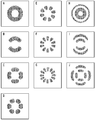
도 2는 환형의 광학 코어를 가지는 예시적인 다중-모드 광섬유의 일부 전파 광학 모드 중 횡방향 진폭 프로파일(transverse amplitude profile)을 개략적으로 예시하고 있다.
도 3은 공간 위상-변조를 공간 필터링과 조합한 도 1의 광학 모드 커플러의 하나의 실시예를 예시하는 구성도이다.
도 4는 도 1 내지 3에 따른 2 개의 광학 모드 커플러로 수신된 광의 직교 선형 편광을 개별 처리하는 광학 모드 커플러를 개략적으로 예시하는 구성도이다.
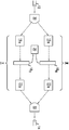
도 5는 다중-모드 광섬유의 선택된 광학 모드(들), 예를 들어 도 1, 3 및 4의 광학 모드 커플러의 내부 또는 외부로 광을 우선적으로 커플링시키는 일부 광학 모드 커플러를 제조하기 위한 방법을 개략적으로 예시하는 흐름도이다.
도 6 및 7은 저해상도에서 공간적으로 변화하는 위상 변조는 광의 진폭과 위상 변조를 생성하는, 도 1, 3A, 3B 및 4의 공간 광변조기(SLM)의 대체 구성을 개략적으로 예시하고 있다.
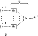
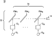
도 8은 N 광원 또는 광검출기를 다중-모드 광섬유의 N 해당 광학 모드에 평행하게 커플링하기 위한 재구성형 Nx1 광학 모드 커플러를 포함하는 광학 장치를 개략적으로 예시하는 구성도이다.
도 9는 도 8의 Nx1 수동 광학 커플러에 대한 하나의 실시예를 예시하는 구성도이다.1 is a schematic diagram illustrating an optical mode coupler configured to preferentially end-couple light into or out of one or more optical modes of a multi-mode optical fiber.
Figure 2 schematically illustrates a transverse amplitude profile of some exemplary propagating optical modes of an exemplary multi-mode optical fiber having an annular optical core.
3 is a block diagram illustrating one embodiment of the optical mode coupler of FIG. 1 in combination with spatial filtering of spatial phase-modulation.
Fig. 4 is a schematic diagram illustrating an optical mode coupler that individually processes orthogonal linear polarization of light received by two optical mode couplers according to Figs. 1 to 3; Fig.
FIG. 5 illustrates a method for fabricating some optical mode couplers that preferentially couple light into or out of a selected optical mode (s) of a multi-mode optical fiber, for example, the optical mode couplers of FIGS. 1, 3, Fig.
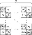
Figures 6 and 7 schematically illustrate an alternative configuration of the spatial light modulator (SLM) of Figures 1, 3A, 3B and 4, where spatially varying phase modulation at low resolution produces amplitude and phase modulation of light.
8 is a block diagram schematically illustrating an optical device including a reconfigurable Nx1 optical mode coupler for coupling an N light source or a photodetector in parallel to the N corresponding optical modes of the multi-mode optical fiber.
9 is a configuration diagram illustrating one embodiment of the Nx1 passive optical coupler of FIG.
본원에서, 다양한 광학 장치가, 예를 들어, 광학 통신 대역, 예를 들어 C, L, 및/또는 S 대역에서의 파장에서 작동되도록 구성될 수 있다. In the present application, various optical devices may be configured to operate at, for example, wavelengths in the optical communication band, e.g., C, L, and / or S bands.
도 1은 광원 또는 광검출기(12)를 다중-모드 광섬유(14)의 하나 이상의 광학 모드에 선택적으로 커플링시키도록 구성될 수 있는 광학 모드 커플러(10)를 개략적으로 예시하고 있다. 광학 모드 커플러(10)는 입력 광학장치(16), 공간 광변조기(SLM)(18), 전자 제어기(20) 및 출력 광학장치(22)를 포함한다.Figure 1 schematically illustrates an
간단하게는, 광학 모드 커플러(10)가, 광원 또는 광검출기(12)를 참고 부호 12로 나타낸 광원인 구성에 대해 기재되어 있다. 당업자는 광학 모드 커플러(10)가 상기 요소(12)가 광원 예컨대 레이저 또는 광학 데이터 변조기이거나 광검출기 예컨대 포토디텍터(photodetector) 또는 광학 데이터 복조기이던지 간에 유사하게 기능할 것임을 이해할 것이다. 예를 들어, 이러한 상이한 실시예는 광학 모드 커플러(10)로, 이로부터 그리고 이의 내에서의 광전파의 방향의 전환, 예를 들어 광학 입력 및 광학 출력의 기능의 교환, 광원 및 광검출기의 교환에 의한 것과 관련된 관련 분야의 당업자에 이해될 것이다.Briefly, the
다양한 실시예에 있어서, 광학 모드 커플러(10)는 요소(12)를 다중-모드 광섬유(14)에 대한 한 세트의 광학 모드의 광학 모드(들) 중 선택된 적절한 서브세트에 우선적으로 모두 광학적으로 커플링시킬 수 있다. 이에서, 상기 세트의 광학 모드는 다중-모드 광섬유(14)에 대한 상대적 직교 모드이다.In various embodiments, the
입력 광학장치(16)는 광원(12)으로부터 광빔을 공간 광변조기(SLM)(18)의 입력 표면으로 유도한다. 입력 광학장치(16)는 광원(12)의 광학 출력, 예를 들어 단일-모드 광섬유의 말단면으로부터의 광빔의 일부를 SLM(18)의 입력 표면의 일부에 평행하게 할 수 있다. 예를 들어, 입력 광학장치(16)는 단면 직경이 SLM(18)의 입력 표면의 상당 부분으로 유도되어지는 광빔을 생성할 수 있다. 입력 광학장치(16)는 수동 광학 시스템, 예를 들어, 렌즈 및/또는 미러 시스템일 수 있고, 광원(12)으로부터의 광을 리디렉션할 수 있는 수동 광학 요소(들)를 포함할 수 있다.The
SLM(18)은 입력 광학장치(16)에 의해 SLM(18)의 입력 표면으로 유도되는 광빔의 파면을 공간적으로 위상-변조시키고, 그에 의해 SLM(18)의 출력 표면으로부터 나오는 변조된 광빔을 생성하도록 구성될 수 있다. SLM(18)은 이차원 (2D) 배열의 개별 제어가능한 광학 위상 변조기를 가진다. 다양한 실시예에 있어서, SLM(18)은 2D 배열의 광학 위상 변조기를 통해 광을 전송하거나 2D 배열의 광학 위상 변조기를 통해 광을 반사시킴으로써 광을 위상-변조시킬 수 있다. SLM(18)에 있어서, 각각의 광학 위상 변조기는 예를 들어 제어가능한 액정셀 또는 변환가능한 미세-전자-기계 시스템 (MEMS) 미러를 포함할 수 있다. 예를 들어, SLM(18)은 공간적으로 변화하는 위상-변조를 적용하기 위해 구성되는 시판되는 반도체 액정 (LCOS) 2D SLM, 또는 개별 변환될 수 있는 시판되는 2D 배열의 MEMS 제어된 마이크로-미러를 포함할 수 있다.The
다양한 실시예에 있어서, SLM(18)의 개별 제어가능한 광학 위상 변조기는 2D 배열에서 거의 균일하거나 불균일하게 간격을 두고 배치될 수 있다. 예를 들어, 개개의 광학 위상 변조기의 중심은 이웃한 개개의 광학 위상 변조기가 대략 균일하게 간격을 두고 배치되도록 균일한 2D 격자의 노드에 위치될 수 있다.In various embodiments, the individually controllable optical phase modulators of the
다양한 실시예에 있어서, SLM(18)의 개별 제어가능한 또는 개개의 광학 위상 변조기는 실질적으로 동일한 작동 특성을 가질 수 있거나 상이한 작동 특성을 가질 수 있다. 예를 들어, SLM(18)의 상이한 개개의 광학 위상 변조기는 이에 입사되는 광빔의 일부에의 동일하거나 상이한 양의 광손실을 생성할 수 있다. 사실상, 개개의 광학 위상 변조기의 이러한 삽입 손실의 양은 광원(12)으로부터 입사되는 광빔의 일부의 상이한 강도에 대해 부분적으로 보상하기 위한 프리픽스 방식(prefixed manner)으로 2D 배열에 대해 공간적으로 변조될 수 있다. 예를 들어, 개개의 광학 위상 변조기는 광원(12)으로부터 SLM(18)의 입력 표면에 입사되는 광빔의 단면에 걸친 가우시안-유사 강도 변화를 부분적으로 보상하는 부분적으로 변조된 손실을 생성하는 상이한 입력 영역일 수 있다.In various embodiments, the individually controllable or individual optical phase modulators of the
전자 제어기(20)는 SLM(18)의 개개의 광학 위상 천이기를 조절하기 위해 전기적으로 접속된다. 예를 들어, 전자 제어기(20)는 입사된 광빔의 파면에 선택된 공간 위상 패턴(들)을 변조하기 위해 SLM(18)의 개개의 광학 위상 천이기를 구성할 수 있다. 전자 제어기(20)는, 예를 들어 광빔은 다중-모드 광섬유(14)의 상이한 선택된 광학 모드(들)에 커플링시키기 위해 재구성될 수 있도록 SLM(18)에 입사되는 광빔의 파면에 상이한 공간적으로 변화하는 위상 패턴을 변조하기 위해 개개의 광학 위상 변조기를 재구성할 수 있다.The
출력 광학장치(22)는 SLM(18)의 출력 표면의 일부로부터의 광을 다중-모드 광섬유(14)의 말단면으로 유도한다. 출력 광학장치(22)는 예를 들어 렌즈 및/또는 미러 시스템을 포함하는 수동 광학 시스템일 수 있다.The output optics 22 directs light from a portion of the output surface of the
일부 실시예에 있어서, 출력 광학장치(22)는 SLM(18)의 출력 표면의 발광부가 다중-모드 광섬유(14)의 말단면에 근사하게 이미지화되도록 위치되고 배향될 수 있다. 일부 실시예에 있어서, SLM(18)의 출력 표면 및 다중-모드 광섬유(14)의 말단면이 출력 광학장치(22)의 켤레면 상에 또는 그 근처에 위치될 수 있다. 예를 들어 SLM(18) 및 다중-모드 광섬유(14)의 말단면은 출력 광학장치(22)의 광학 중심으로부터의 켤레면 중 상기 가장 근접한 것의 거리의 20 % 이하, 바람직하게는 10 % 이하로 켤레면의 가장 근접한 것에 인접하여 위치될 수 있다. 일부 이러한 실시예에 있어서, 출력 광학장치(22)는 또한 다중-모드 광섬유(14)의 상기 논의한 선택된 광학 모드(들)를 활성화시키기 위해 발광되는 다중-모드 광섬유(14)의 더 작은 말단면에의 SLM(18)의 출력 표면의 발광부 및/또는 그의 부분을 근사하게 이미지화하기 위한 축소화를 제공할 수 있다. 출력 광학장치(22)는 또한 다중-모드 광섬유(14)의 말단면에서의 근사 이미지에서 예를 들어 1/3 또는 심지어 1/5 이상 SLM(18)의 출력 표면의 발광부를 축소할 수 있다. 이러한 축소화는 SLM(18)이 작은 영역을 가진 다중-모드 광섬유(14)의 말단면에 고해상 이미지를 생성하게 할 수 있다.In some embodiments, the output optics 22 can be positioned and oriented such that the light-emitting portion of the output surface of the
다른 실시예에 있어서, 출력 광학장치(22)는 다중-모드 광섬유(14)의 말단면에 SLM(18)의 출력 표면의 발광부의 푸리에 변환을 근사하게 이미지화하기 위해 위치되고 배향된다. 이러한 실시예에 있어서, SLM(18)의 출력 표면 및 다중-모드 광섬유(14)의 말단면은 출력 광학장치(22)의 초점면(들) 상에 또는 그 근처에 위치할 수 있다. 예를 들어, SLM(18)의 출력 표면 및 다중-모드 광섬유(14)의 말단면은 출력 광학장치(22)의 광학 중심으로부터의 초점 길이의 거리의 20 % 이하, 바람직하게는 10 % 이하로 가장 근접한 초점면에 각각 인접하여 위치될 수 있다. 일부 실시예에 있어서, 다중-모드 광섬유(14)의 말단면은 또한 SLM(18)의 출력 표면의 발광부의 푸리에 변환의 공간 필터링을 제공할 수 있다. 특히, 말단면은 SLM(18)의 규칙적 2D 격자 구조에 의해 출력 광학장치(22)의 제 2 초점면에 생성되는 명점(bright spot)이 말단면에 입사되지 않도록 충분히 작을 수 있다.In another embodiment, the output optics 22 is positioned and oriented to approximate the Fourier transform of the light emitting portion of the output surface of the
다양한 실시예에 있어서, 광학 모드 커플러(10)는 상대적 위상 및 상대적 진폭이 다중-모드 광섬유(14)의 말단면에서의 하나 이상의 선택된 광학 모드의 것과 실질적으로 매칭되는 공간 의존성을 가지는 광빔을 출력하도록 구성될 수 있다. 상기 세트의 상이한 광학 모드는 예를 들어 상대적 직교 광학 모드일 수 있다. 출력광의 위상 및 진폭은 선택된 선형 전파(LP)의 것과 근사하게 매칭될 수 있거나 다중-모드 광섬유(14)의 말단면에의 실제 전파 광학 모드(들)의 것과 근사하게 매칭될 수 있다. 출력 광빔 및 선택된 광학 전파 모드(들)에서의 공간 위상 및 진폭 변화의 근사 매칭은 SLM(18)에 입사되는 광빔의 공간 위상 변조에 의해 생성될 수 있다.In various embodiments, the
도 2는 환형 광학 코어를 가진 다중-모드 광섬유의 예에 대한 상대적 직교 전파 광학 모드 A, B, C, D, E, F, G, H, I, 및 J의 공간 진폭 프로파일을 개략적으로 예시하고 있다. 도 2에 있어서, 상대적으로 큰 진폭 구간은 어두운 구간으로 나타내고 상대적으로 작은 진폭 구간은 백색 구간으로 나타낸다. 전파 광학 모드 A-J의 일부의 위상은 예를 들어 영이 아닌 각운동량에 해당하는 다중-모드 광섬유의 축 주변에 작지 않은 와인딩 의존성(winding dependency)을 가진다. 이러한 광학 모드의 선택된 조합 또는 필드가 복합 횡방향 공간 의존성을 가지는 다른 광학 모드의 선택된 조합에 우선적으로 엔드-커플링시키기 위해, 전자 제어기(20)의 일부 실시예는 이에 입사되는 광의 파면에 공간적으로 변화하는 위상 변조 패턴을 생성하기 위해 SLM(18)을 작동하도록 구성될 수 있다.Figure 2 schematically illustrates the spatial amplitude profiles of the relative orthogonal propagation optical modes A, B, C, D, E, F, G, H, I, and J for an example of a multi-mode optical fiber with an annular optical core have. In FIG. 2, a relatively large amplitude section is represented by a dark section and a relatively small amplitude section is represented by a white section. The phase of a part of the propagation optical mode A-J has a small winding dependency around the axis of the multi-mode optical fiber corresponding to angular momentum, for example, not zero. In order to preferentially end-couple a selected combination or field of such optical modes to a selected combination of other optical modes having complex lateral spatial dependence, some embodiments of the
도 3은 공간 위상 변조를 공간 필터링과 조합하는 도 1의 광학 모드 커플러(10)의 특정 실시예(10')를 예시한다. 광학 모드 커플러(10')는 입력 광학장치(16), SLM(18), 전자 제어기(20), 및 출력 광학장치(22)를 포함한다.FIG. 3 illustrates a specific embodiment 10 'of the
광학 모드 커플러(10')에 있어서, 입력 광학장치(16), SLM(18) 및 전자 제어기(20)는 도 1의 광학 모드 커플러(10)에 대해 기술된 바와 같이 구성될 수 있다.For optical mode coupler 10 ',
광학 모드 커플러(10')에 있어서, 출력 광학장치(22)는 제 1 집속 광학 렌즈 또는 미러 시스템(24), 제 2 집속 광학 렌즈 또는 미러 시스템(26), 및 임의의 광학 구경 조리개(28)를 포함한다. 집속 광학 렌즈 또는 미러 시스템(24, 26)은 다중-모드 광섬유(14)의 말단면에 SLM(18)의 출력 표면의 일부의 근사 이미지를 형성한다. 제 2 집속 광학 렌즈 또는 미러 시스템(26) 및/또는 임의의 광학 구경 조리개(28)는 공간 필터링을 제공한다.In optical mode coupler 10 ', output optics 22 includes a first focusing optical lens or
공간 필터링을 제공하기 위해, 광학 모드 커플러(10')의 요소는 통상적으로 특별하게 공간적으로 위치되고, 제 2 집속 렌즈 또는 미러(26)에 의해 형성된 광학 구경 및/또는 임의의 광학 구경 조리개(28)는 특정 공간 형태를 가지도록 구성된다. 특별한 공간적 포지셔닝과 관련하여, SLM(18)의 출력 표면은 제 1 집속 렌즈 또는 미러 시스템(24)의 초점면 상에 또는 그 근처에 위치되고, 제 2 집속 렌즈 또는 미러 시스템(26) 및/또는 임의의 광학 구경 조리개(28)는 제 1 집속 렌즈 또는 미러 시스템(24)의 초점면 상에 또는 그 근처에 위치된다. 특별한 공간 형태와 관련하여, 제 2 집속 렌즈 또는 미러 시스템(26) 및/또는 임의의 광학 구경 조리개(28)는 제 1 집속 렌즈 또는 미러 시스템(24)이 푸리에 변환면에 생성하는 SLM(18)의 출력 표면의 특정 고차의 명점(bright spot)을 차단하기 위해 구성될 수 있다.In order to provide spatial filtering, the elements of the optical mode coupler 10 'are typically specially positioned spatially and have an optical aperture formed by the second focusing lens or
특정 고차의 명점은 SLM(18)의 광학 위상 천이기의 2D 배열 구조에 의해 생성된다. 상기 특정 고차의 점의 위치는 SLM(18)의 2D 배열에서 개개의 광학 위상 변조기의 중심들 사이에서 간격 거리에 기초하여 관련 분야에서의 당업자에 의해 용이하게 결정될 것이다. 특정 고차의 점은 통상적으로 SLM(18)의 출력 표면의 푸리에 이미지의 중심 주변에 중심이 있는 균일 격자 상에 있다. 따라서, 일부 실시예에 있어서, 특정 고차 명점은 필터링될 수 있고, 이는 상기 명점이 제 2 집속 렌즈 또는 미러 시스템(26) 또는 임의의 광학 구경 조리개(28)의 물리적 구경의 외부에 위치하기 때문이다.Certain higher order bright spots are created by the 2D array structure of the optical phase shifter of the
도 4는 광의 상대적으로 직교 선형 편광을 개별 처리하도록 구성되는 광학 모드 커플러(10'')를 예시하고 있다. 광학 모드 커플러(10'')는 평행 광학 시퀀스(H 및 V), 제 1 및 제 2 편광 빔 분배기(30, 32), 및 전자 제어기(20)를 포함한다.Figure 4 illustrates an
광학 모드 커플러(10'')에 있어서, 각각의 광학 시퀀스(H, V)는 광의 2 개의 상대적 직교 선형 편광 성분을 개별 처리하기 위해 입력 광학장치(16H, 16V), SLM(18H, 18V), 및 출력 광학장치(22H, 22V)를 포함한다. 입력 광학장치(16H, 16V); SLM(18H, 18V); 및 출력 광학장치(22H, 22V)는 하기 기재된 것을 제외하고 도 1 및/또는 3에서의 각각의 입력 광학장치(16), SLM(18), 및 출력 광학장치(22)와 유사하게 구성될 수 있다. In the
광학 모드 커플러(10'')에 있어서, H 광학 시퀀스의 입력 광학장치(16H)는 제 1 편광 빔 분배기(30)로부터의 하나의 선형 편광의 광을 수신하고, 및 V 광학 시퀀스의 입력 장치(16v)는 제 1 편광 빔 분배기(30)의 상대적 직교 선형 편광의 광을 수신한다.In the
광학 모드 커플러(10'')에 있어서, 각각의 SLM(18H, 18V)은 예를 들어 공간적으로 변화하는 방식에서 이에 입사되는 선형 편광의 광을 위상 변조하기 위해 구성될 수 있다. 따라서, 각각의 SLM(18H, 18V)은 하나의 선형 편광의 공간적으로 위상-변조된 광빔을 출력하도록 구성된다.In the
광학 모드 커플러(10'')에 있어서, 전자 제어기(20)는 각각의 SLM(18H, 18V)을 제어하기 위해 접속된다. 따라서, 전자 제어기(20)는 각각의 SLM(18H, 18V)이 하나 이상의 선택된 위상 패턴, 예를 들어 공간적으로 변화하는 위상 패턴을 가진 해당하는 선형 편광의 광의 파면을 위상-변조시키는 것을 야기하도록 구성된다.In
광학 모드 커플러(10'')에 있어서, H 광학 시퀀스의 출력 광학장치(22H)는 하나의 선형 편광의 광빔을 제 2 편광 빔 분배기(32)에 전송하고, V 광학 시퀀스의 출력 광학장치(22V)는 상대적 직교 선형 편광의 광빔을 제 2 편광 빔 분배기(32)에 전송한다.In the
광학 모드 커플러(10'')에 있어서, 제 2 편광 빔 분배기(32)는 H 및 V 광학 시퀀스의 두 선형 편광의 광빔을 중첩시킨다. 편광 빔 분배기(32)는 중첩된 광빔으로부터 다중-모든 광섬유(14)의 말단면에 이미지를 생성한다. 이미지에 있어서, 평균 진폭, 평균 위상 및/또는 평균 선형 편광은 픽셀-대-픽셀(pixel-to-pixel)로부터 변화될 수 있다. 각각의 이러한 이미지에 있어서, 진폭, 위상 및 선형 편광은 광이 다중-모드 광섬유(14)에 대한 선택된 광학 모드(들), 예를 들어 실제 전파 광학 모드를 우선적으로 활성화시키도록 설정될 수 있다.In the
다양한 실시예에 있어서, SLM(들)(18, 18H, 18V)의 광학 위상 변조기는, 즉, 전자 제어기(20)에 의해 다중-모드 광섬유(14)의 선택된 광학 모드(들)에 우선적으로 커플링시키기 위해 입력 광학장치(16, 16H, 16V)로부터 수신된 광의 파면을 위상-변조시키도록 구성될 수 있다. SLM(들)(18, 18H, 18V)은 위상, 진폭, 및 편광에 있어서의 공간 변화가 다중-모드 광섬유(14)의 근접한 말단면에 선택된 광학 모드(들) 중의 것과 근사하게 매칭되는 출력 광빔(들)을 생성하기 위해 입사 파면, 예를 들어 평면 파면을 위상-변조시킬 수 있다. 특히, 광학 모드 커플러(10, 10', 10'')는 다중-모드 광섬유(14)의 선택된 광학 모드(들)로의 이러한 광의 커플링을 향상시키거나 근사하게 최적화하도록 구성될 수 있고/있거나 다중-모드 광섬유(14)의 잔여 비선택된 광학 모드(들)로 이러한 광의 커플링을 감소시키거나 근사하게 최소화하도록 구성될 수 있다.In various embodiments, the optical phase modulator of the SLM (s) 18, 18 H , 18 V is preferentially assigned to the selected optical mode (s) of the multi-mode
일부 실시예에 있어서, 광학 모드 커플러(10'')는 광원(12)으로부터의 광을 다중-모드 광섬유(14)의 선택된 실제 광학 전파 모드(들)로 우선적으로 커플링시키도록 구성되거나 구성될 수 있다. 일부 이러한 실제 광학 전파 모드는 다중-모드 광섬유(14)의 단면에 걸쳐 공간적으로 변화되는 편광을 가질 수 있고, 광학 모드 커플러(10'')는 편광이 다중-모드 광섬유(14)의 말단면에 대해 실질적으로 매칭시키는 방식으로 변화되는 광을 출력시키도록 구성될 수 있다. 사실상, 광학 모드 커플러(10'')는 상대적 직교 선형 편광의 광을 개별 위상-변조시키고, 다중-모드 광섬유(14)의 말단면에 이미지를 생성하기 위해 이러한 개별 위상-변조된 광을 중첩시키는 능력을 제공할 수 있다. 이러한 이미지에 있어서, 편광, 진폭, 및 위상은 다중-모드 광섬유(14)의 말단면에 대해 픽셀-대-픽셀 방식으로, 즉 광학 모드 커플러(10'')에 의해 개별로 선택적으로 실질적으로 구성될 수 있다. 이러한 이유로, 광학 모드 커플러(10'')는 다중-모드 광섬유(14)의 선택된 실제 광학 전파 모드(들)로의 광의 개선되거나 대체로 최적화된 커플링을 제공할 수 있고/있거나 다중-모드 광섬유(14)의 비선택된 실제 광학 전파 모드(들)로의 이러한 광의 커플링을 감소시키거나 대체로 최소화되도록 구성될 수 있다.In some embodiments, the
도 5는 다중-모드 광섬유(14)에 대한 한 세트의 광학 모드의 선택된 광학 모드(들)로 광을 우선적으로 전송하는, 광학 커플러(10, 10', 10'')의 특정 실시예를 구성하기 위한 방법(40)을 예시하고 있다. 예를 들어, 상기 방법(40)은 도 1, 3, 및 4의 광학 커플러(10, 10', 10'')의 전자 제어기(20)를 구성하기 위해 사용될 수 있다.5 illustrates a specific embodiment of an
상기 방법(40)은 다중-모드 광섬유(14)의 굴절률 프로파일에 기초한 다중-모드 광섬유(14)의 말단면에의 상기 세트의 광학 모드의 공간 의존성을 결정하는 것을 포함한다(단계 42). 통상적으로, 단계 42는 공간 진폭 및 공간 위상 의존성 및 가능하게는 다중-모드 광섬유(14)에서의 상기 세트의 광학 모드의 공간 선형 편광 의존성을 조사하는 것과 관련된다. 본원에서, 진폭, 위상, 및 편광 공간 의존성은 광학 모드의 광학 필드 중의 것, 예를 들어 광학 모드의 전기장 및/또는 자기장의 공간 의존성이다. 당업자는 광학 모드의 전기장 및 자기장을 결정하기 위한 공지된 방법을 사용함으로써 이러한 세트의 광학 모드의 이러한 공간 의존성을 용이하게 결정할 수 있을 것이다. 예를 들어, 본원에 전문이 참조로서 포함된 프로젝트 보고서 "Fiber Modes [Theory and Simulation]" by Ayman M. Mansour et ai (Fall 2005/2006), publication EE-0903729 of the Electrical Engineering Department at the University of Jordan은 일부 이러한 방법을 기재하고 있다.The
상기 세트의 상이한 광학 모드는 통상적으로 작거나 무시할 정도로 작은 다중모드 광섬유(14)의 2D 말단면에 대해 중첩 적분을 가진다. 사실상, 상기 세트의 광학 모드는 상호 직교일 수 있고 상기 중첩 적분이 또한 다중-모드 광섬유(14)에서의 상기 세트의 각각의 하나의 광학 모드로의 입사된 광의 커플링의 크기를 결정하도록 이러한 중첩 적분에 대해 정규화시킬 수 있다. 상기 세트의 광학 모드는 예를 들어 상이한 선형 편광된 (LP) 광학 모드일 수 있거나 예를 들어 다중-모드 광섬유(14)의 실제 전파 광학 모드의 기초 세트의 일부 또는 모두일 수 있다.The different optical modes of the set typically have a superimposition integral to the 2D end face of a multimode
상기 방법(40)은 광이 상기 세트의 하나 이상의 광학 모드의 선택된 조합을 우선적으로 활성화시키기 위해 다중-모드 광섬유(14)의 말단면에 입사되는 광의 광학 필드에 대해 위상의 공간 의존성, φ(x,y), 진폭, A(x,y)를 결정하는 것(단계 44)을 포함한다. 본원에서, 데카르트 좌표 (x,y)는 다중-모드 광섬유의 2D 말단면에 지점 또는 픽셀을 확인한다. 예로서, 상기 세트의 개개의 광학 모드는 다중-모드 광섬유(14)의 말단면에서 그 사이의 중첩 적분에 대해 상호 직교일 수 있다. 이러한 한 세트의 광학 모드에 대해, 광의 광학 필드가 다중-모드 광섬유(14)의 말단면에서의 광학 모드 중 선택된 하나의 것과 근사한 비율로 진폭을 가지는 경우 광은 광학 모드의 선택된 하나에 우선적으로 커플링될 수 있고 다중-모드 광섬유(14)의 말단면에서, 광학 모드 중 선택된 하나의 것과 근사하게 동등한, 즉 일정한 천이(constant shift)까지의 위상을 가진다.The
결정 단계 44는 또한 선택적으로 광이 상기 세트의 광학 모드 중 선택된 조합의 것을 우선적으로 활성화시키도록 광의 선형 편광에 해당하는 국소적 수치(local value)를 결정하는 것과 관련될 수 있다. 예를 들어, 결정 단계 44는 광섬유(14)의 말단면으로의 광출력을 위해 별도의 공간 위상 및 진폭 프로파일, 즉 {φH(x,y), AH(x,y)} 및 {φV(x,y), AV(x,y)}를 결정하는 것을 포함할 수 있다. 예를 들어, 이러한 {φH(x,y), AH(x,y)} 및 {φV(x,y), AV(x,y)} 프로파일은 도 4의 각각의 H-편광 및 V-편광 SLM(18H 및 18V)을 구성하는데 사용될 수 있다.The determining
상기 방법(40)은 다중-모드 광섬유(14)에 대한 상기 세트의 하나 이상의 선택된 광학 모드에 우선적으로 광학 엔드-커플링시키기 위해 적합한 출력 광빔을 생성하기 위해 SLM(들)(18, 18H, 18V)이 입사된 광을 위상-변조시키는 것을 야기하도록 전자 제어기(20)를 구성하는 것을 포함한다(단계 46). 전자 제어기(20)는 SLM(들)(18, 18H, 18V)이 SLM(18)의 2D 출력 표면에서의 광학 필드(들)가 대체로 하기로 정의된 출력 광빔(들)을 생성하도록 구성된다:The
![]()
![]()
식 (1a)에 있어서, SLM(18, 18H, 18V)의 2D 출력 표면에서의 지점에 대한 데카르트 좌표는 한 쌍의 대문자, 즉 X 및 Y로 기재된다. 각각의 출력 광학 장치(22, 22H, 22V)는 해당하는 SLM(18, 18H, 18V)의 출력 표면의 발광부의 이미지 또는 다중-모드 광섬유(14)의 말단면에서의 상기 발광 출력 표면의 이미지 또는 푸리에 변환을 형성한다. 따라서, 각각의 SLM(18, 18H, 18V)의 출력 표면에의 발광점(X,Y)은 다중-모드 광섬유(14)의 말단면에의 지점(x,y)에 이미지화되거나 각각의 SLM(18, 18H, 18V)의 발광 출력 표면의 푸리에 변환의 지점은 다중-모드 광섬유(14)의 말단면에의 지점(x,y)에 이미지화된다. 전자의 경우에 있어서, 각각의 SLM(18, 18H, 18V)의 2D 출력 표면에서의 (X,Y)의 발광점은 대체로 하기와 같이 다중-모드 광섬유(14)의 2D 말단면에서의 (x,y)와 관련된다:In equation (1a), the Cartesian coordinates for a point on the 2D output surface of the SLM (18, 18 H , 18 V ) are described as a pair of upper case letters, X and Y. Each of the output optics 22, 22 H , and 22 V has an image of the light emitting portion of the output surface of the corresponding
![]()
![]()
이러한 경우에 있어서, 출력 광학장치(22, 22H, 22V)는 인자 "m"에 의해 SLM(18, 18H, 18V)의 출력 표면에서의 발광 패턴의 선형 치수를 확대하고, m은 대개 1 미만이다. 다중-모드 광섬유(14)의 2D 말단면에서, 출력 광학장치(22, 22H, 22V)는 통상적으로 광학 필드(들)가 대체로 하기 필드(들)에 비례하는 이미지를 생성한다.In this case, the output optics 22, 22 H , 22 V magnify the linear dimension of the emission pattern at the output surface of the
![]()
![]()
후자의 경우, 당업자는 출력 광학장치(22, 22H, 22V)가 SLM(18, 18H, 18V)의 출력 표면에서의 발광 패턴의 광학 필드(들)를 다중-모드 광섬유(14)의 말단면에서 광학 필드(들)과 어떻게 연관시키는지를 본 개시물에 기초하여 이해할 것이다.In the latter case, those skilled in the art the output optics (22, 22 H, 22 V) is the optical field (s) of the light-emitting pattern at the output surface multiple of the SLM (18, 18 H, 18 V) - mode optical fiber (14) (S) at the end face of the optical element (s) will be understood based on the present disclosure.
SLM(18, 18H, 18V)이 식 (1a)에서 정의한 바와 같은 광학 필드(들)를 생성하도록 야기하기 위해, 전자 제어기(20)는 데카르트 좌표 (X,Y)에 의해 색인된 저해상 2D 배열의 픽셀과 같은 SLM(18, 18H, 18V)의 2D 배열의 개개의 광학 위상 변조기를 작동시킬 수 있다. 각각의 이러한 픽셀은 SLM(18, 18H, 18V)의 국소적으로 위치한 개개의 광학 위상 변조기의 국소적 그룹을 포함하고, SLM(18, 18H, 18V)의 각각의 개개의 광학 위상 변조기는 국소적 그룹 중 한 그룹에 속한다. 다양한 실시예에 있어서, 개개의 국소적 그룹은 상이한 크기를 가질 수 있고, 예를 들어 SLM(18, 18H, 18V)의 2, 3, 4, 5, 6, 7, 8개 이상의 상대적으로 국소적으로 위치한 개개의 광학 위상 변조기를 가진다.To cause the
각각의 국소적 그룹은, 즉 국소적 그룹의 저해상 2D 배열의 픽셀의 격자 규모로 입사광의 평균 위상 및 진폭 변조를 생성하기 위해 전자 제어기(20)에 의해 구성될 수 있다. 즉, 각각의 SLM(18, 18H, 18V)의 광학 위상 변조기에 의한 공간적으로 변화하는 위상 변조는, 예를 들어 (X,Y) 좌표에 의해 색인된 저해상의 2D 배열의 픽셀에서 조합된 공간적으로 변화하는 진폭 및 위상 변조를 생성한다.Each local group can be configured by the
도 6 및 7은 이러한 공간적으로 변화하는 진폭 및 위상 변조가 SLM(18)에 의한 위상 변조로부터 초래되는 저해상 2D 배열의 픽셀에 대한 대체적인 예시적 구성을 예시하고 있다. 각각의 예시적 구성에 있어서, 저해상 배열의 개개의 픽셀은 SLM(18)의 (a,b)-색인된 쌍의 이웃하는 개개의 광학 위상 변조기를 포함한다. 지점(X,Y)에서의 픽셀은 SLM(18)의 이웃하는 행에 위치하는, (a,b)-색인된 쌍의 광학 위상 변조기를 포함한다. (a,b)-색인된 쌍은 도 6에 예시된 한쌍의 행 구조에서 SLM(18)의 동일한 열에 위치하고 도 6에 예시된 체커보드 구성에서 SLM(18)의 이웃하는 열 및 행에 대각선으로 위치한다. 예를 들어, 도 6-7은 (X,Y) 좌표 (1,1), (1,2), (1,N-1), (1, N), (M,l), (M,2), (M,N-1), 및 (M,N)을 가진 NXM 배열의 픽셀을 확실하게 보여주고, 이는 각각의 쌍의 참조부호 {11a, 11b}, {12a, 12b}, {1(N-l)a, 1(N-l)b}, {lNa, lNb}, {M1a, M1b}, {M2a, M2b} ,{M(N-1)a, M(N-1)b}, 및 {1Na, 1Nb}를 가지는 (a,b)-색인된 광학 위상 변조기를 포함한다.6 and 7 illustrate alternative exemplary configurations for pixels in a low resolution 2D array resulting from this spatially varying amplitude and phase modulation resulting from phase modulation by the
도 6 및 7의 구성에 있어서, 전자 제어기(20)는 입사 광빔의 파면에서의 각각의 위상 Ωa(X,Y) 및 Ωb(X,Y)를 변조하기 위해 (X,Y)에서의 픽셀에 속하는 (a,b)-색인된 쌍에 속하는 a-색인된 및 b-색인된 광학 위상 변조기를 구성한다. 위상 Ωa(X,Y) 및 Ωb(X,Y)는 예를 들어 하기에 의해 정의될 수 있다:In the configuration of Figures 6 and 7, in an electronic controller 20 (X, Y) for modulating the respective phases Ω a (X, Y) and Ω b (X, Y) in the incident light beam wave front Indexed optical phase modulator belonging to the (a, b) -indexed pair belonging to the pixel. The phases? A (X, Y) and? B (X, Y) can be defined, for example, by:

본원에서, Ka 및 Kb는 SLM(18)의 개개의 광학 위상 변조기를 이의 작동 범위 내에 위치할 수 있도록 설정되는 값인 정수이고, Amax는 예를 들어 SLM(18)의 출력 표면에서의 최대 진폭 A(x, y)일 수 있거나 다른 상수값일 수 있다. Ka 및 Kb의 값은 SLM(18)에 의해 출력된 공간적으로 위상-변조된 광에 영향을 미치지 않는다. 식 (2a) - (2b)에 기초하여, (X,Y)에서의 픽셀에 대해 평균화된 광학 필드의 복소수값(complex value)은 하기에 비례한다:Here, K a and K b are integers which are values that are set so that the individual optical phase modulators of the

식 (3)으로부터, 관련 기술의 당업자는 공간적으로 변화하는 방식으로 위상-변조될 수 있는 SLM(18)의 출력 표면에서 나가는 광은 저해상 2D 배열의 픽셀, 즉 좌표 (X,Y)에 의해 색인된 픽셀 중 개개의 것에 대해 평균화된 경우 식 (1a)과 같이 변조된 위상 및 진폭 모두로 나타낼 수 있다는 것을 이해할 것이다. 따라서, ![]()
![]()
도 6 및 7의 구성에 대해, 도 1, 3 및 4의 각각의 SLM(18, 18H, 18V)은 픽셀의 개개의 것에 대해 평균화되는 경우, 진폭 및 위상이 다중-모드 광섬유(14)의 말단면에서의 선택된 광학 모드(들)에 대해 적합한 식 (1b)를 만족시키는 광을 출력하기 위해 식 (2a) - (2b)에 따라 작동될 수 있다.6 and 7, when the
도 4의 광학 모드 커플러(10'')에 있어서, SLM(18V) 및 SLM(18H)은 다중-모드 광섬유(14)의 선택된 광학 모드(들)의 각각의 V 및 H 선형 편광 성분에 대해 변조된 광빔을 출력하도록 개별로 구성될 수 있다. 즉, SLM(18V)은 이의 출력 표면에서 A(X,Y) = AV(X,Y) 및 φV(X,Y) = φV(X,Y)인 식 (2a) - (2b)에 따라 광빔을 위상-변조하기 위해 전자 제어기(20)에 의해 구성될 수 있고, SLM(18H)은 A(X,Y) = AH(X,Y) 및 φH(X,Y) = φH(X,Y)인 식 (2a) - (2b)에 따라 광빔을 위상-변조하기 위해 전자 제어기(20)에 의해 구성될 수 있다. 본원에서, AV(X,Y) 및 φV(X,Y)는 다중-모드 광섬유(14)의 말단면에서의 선택된 광학 모드(들)의 V 선형 편광 성분의 진폭 및 위상이고, AH(X,Y) 및 φH(X,Y)는 다중-모드 광섬유(14)의 말단면에서의 선택된 광학 모드(들)의 H 선형 편광 성분의 진폭 및 위상이다.In the
도 8은 N 광원 또는 광검출기(121 - 12N)를 다중-모드 광섬유(14)의 N개의 해당 광학 모드에 평행하게 우선적으로 커플링시키기 위한 재구성형 Nx1 광학 모드 커플러(52)를 포함하는 광학 장치(50)를 예시하고 있다. 재구성형 Nx1 광학 모드 커플러(52)는 N 1x1 재구성형 광학 모드 커플러(101 - 10N) 및 수동 Nxl 광학 커플러(54)를 포함한다.Figure 8 includes a reconfigurable Nx1
각각의 1x1 재구성형 광학 모드 커플러(101 - 10N)는 광원 또는 광검출기(121 - 12N) 중 해당하는 것에 커플링되는 광학 입력을 가지고 수동 Nx1 광학 커플러(54)의 해당하는 광학 입력에 연결되는 광학 출력을 가진다. 각각의 1x1 재구성형 광학 모드 커플러(101 - 10N)는 도 1, 3, 및 4의 1x1 광학 모드 커플러(10, 10', 10'') 중 하나와 유사하게 구성될 수 있다.Each 1x1 reconstructive optical mode coupler 10 1 - 10 N has an optical input coupled to a corresponding one of the light sources or optical detectors 12 1 - 12 N and coupled to a corresponding optical input of a
수동 Nxl 광학 커플러(54)는 N개의 광학 입력에서 수신된 N개의 광빔을 중첩시키고 광섬유(14)의 말단면에 생성된 조합된 광빔을 유도한다. 이러한 중첩으로 인해, N개의 1x1 광학 커플러(101 - 10N)에서의 SLM의 출력 표면의 발광부의 이미지 또는 상기 출력 표면의 발광부의 푸리에 변환은 다중-모드 광섬유(14)의 말단면에 수동 nx1 광학 커플러(54)에 의해 평행하게 형성될 수 있다. 수동 Nx1 광학 커플러(54)는 상이한 광빔의 이러한 중첩을 형성하기 위한 종래의 수동 광학 시스템일 수 있다. 예를 들어, 수동 Nx1 광학 커플러(54)는 종래의 미러, 렌즈, 편광 분배기 등으로 형성될 수 있다.The passive Nxl
수동 Nx1 광학 커플러(54)의 2x1 실시예는, 예를 들어 하나의 1x1 광학 모드 커플러(101 - 10N)는 ½ 또는 부분적으로 은도금한 미러의 후면을 비출수 있고 다른 1x1 광학 모드 커플러(101 - 10N)는 ½ 또는 부분적으로 은도금한 미러의 측면을 비출수 있도록 위치한 하나 이상의 ½ 또는 부분적으로 은도금한 미러를 포함할 수 있다. 조합된 전송 및 반사에 의해, 이러한 ½ 또는 부분적으로 은도금한 미러는평행하게 이러한 1x1 광학 모드 커플러(101 - 10N) 모두로부터의 광빔을 다중-모드 광섬유(14)의 말단면에 평행하게 리디렉션할 수 있다.The 2x1 embodiment of the passive Nx1
도 8의 수동 Nxl 광학 커플러(54)의 하나의 예시적인 실시예는 예를 들어 도 9에서 2 초과의 N을 사용하는 이러한 N개의 미러(PSM1 - PSMN)에 대해 예시된 바와 같이, N 또는 (N-1)개의 부분적으로 은도금한 미러의 캐스케이드를 포함한다. 이러한 실시예에 있어서, 각각의 1x1 광학 모드 커플러(101 - 10N)는 이로부터의 출력광을 부분적으로 은도금된 미러(PSM1 - PSMN)의 해당하는 것의 정면으로 유도할 것이다. 이러한 캐스케이드에 있어서, 각각의 부분적으로 은도금된 미러(PSM1 - PSMN)는 또한 이의 정면으로부터 반사된 광을 캐스케이드의 다음의 부분적으로 은도금된 미러(PSM1 - PSMN)의 후면 또는 다중-모드 광섬유(14)의 말단면으로 유도하기 위해 위치될 수 있다.One exemplary embodiment of
관련 분야의 당업자는 본 개시물로부터 종래의 다른 수동 광학 장치가 도 8의 수동 Nx1 광학 커플러(54)를 구성하기 위해 사용될 수 있음을 이해할 것이다.Those skilled in the relevant art will appreciate that other conventional passive optical devices from the present disclosure may be used to construct the passive Nxl
도 8과 관련하여, 광학 장치(50)는 일부 실시예에서 광학 데이터 송신기일 수 있다. 이러한 실시예에 있어서, 각각의 N개의 광원 또는 광검출기(121 - 12N)는 예를 들어 수신된 디지털 데이터 스트림(들)으로부터 데이터 변조된 광캐리어를 발생시키는 별도의 광학 데이터 송신기일 수 있다. 예를 들어, 각각의 이러한 광송신기는 디지털 데이터 스트림(들)을 가진 하나 또는 다중 파장 채널 내에서 광캐리어를 변조하기 위한 종래의 전기 또는 광학 장치를 포함할 수 있다. 이러한 실시예에 있어서, 수동 Nx1 광학 커플러(54)는 N개의 광학 전송기의 상이한 것으로부터의 데이터-변조된 광캐리어를 다중-모드 광섬유(14)의 광학 모드의 상이한 것 상에서 선택적으로 재구성적으로 다중화할 수 있다.8,
도 8과 관련하여, 광학 장치(50)는 일부 대안적인 실시예에서 광학 데이터 수신기일 수 있다. 이러한 실시예에 있어서, 각각의 N개의 광원 또는 검출기(121 - 12N)는 예를 들어 수신된 데이터 변조된 다중-모드, 광캐리어로부터의 복조된 디지털 데이터 스트림을 위한 별도의 광수신기일 수 있다. 예를 들어, 각각의 이러한 광수신기는 하나 또는 다중 파장 채널을 포함할 수 있는, 광학 모드의 한 모드의 데이터-변조된 광캐리어로부터의 디지털 데이터 스트림(들)을 복조하기 위한 종래의 전기 및 광학 장치를 포함할 수 있다. 이러한 실시예에 있어서, 수동 Nxl 광학 커플러(54)는 다중-모드 광섬유(14)의 광학 모드 중 상이한 모드의 광을 분리하고 광학 모드 중 상이한 모드에 수신된 광을 N개의 광수신기의 상이한 수신기에 대해 유도하기 위해 데이터-변조된, 다중-모드 광캐리어를 역다중화한다.8,
상기 도 1, 3, 및 4의 광학 모드 커플러(10, 10', 10'')의 다양한 실시예는 9월 16일에 Roland Ryf에 의해 출원된 미극특허출원, 명칭 "OPTICAL SYSTEM FOR SIGNAL AMPLIFICATION USING A MULTIMODE FIBER"에 개시된 광학 장치와 유사한 광학 장치에서 사용될 수 있다. Roland Ryf의 이 미국특허출원은 전문이 본원에 참조로서 포함된다. 도 1, 3, 및 4의 광학 모드 커플러(10, 10', 10'')는 예를 들어 위상 마스크가 이에서 논의된 다중-모드 광섬유의 도파 모드 중 다양한 것으로 광을 우선적으로 커플링시키기 위한 기능을 할 수 있는 경우 임의의 위상 마스크 및 광증폭기의 해당하는 입력 및 출력 광학장치 및 상기-포함된 미국특허출원에 기재된 다른 광학 장치를 대체할 수 있다. 예를 들어, 본 출원에 기재된 광학 모드 커플러는 상기 포함된 미국특허출원의 광학-단일 커플러 및/또는 광학-펌프 커플러에서의 위상 마스크 중 일부 또는 모두를 대체할 수 있다.Various embodiments of the
예시적인 실시예의 상세한 설명 및 도면은 단순히 본 발명의 원리를 예시한다. 당업자가 본원에서 명확하게 기재되거나 보여지지 않지만 본 발명의 원리를 구현하고 청구된 본 발명에 포함되는 다양한 배열을 고안할 수 있다는 것은 이해될 수 있다. 또한, 본원에서 인용된 모든 예는 원칙적으로 본 발명의 원리 및 나아가 본 기술에 대해 본 발명자에 의해 주어진 개념을 이해하는데 보조하기 위한 교육적 목적을 위한 것으로 의도된다. 또한, 본 발명의 원리, 양태, 및 실시예, 및 이의 특정 실시예를 인용하는 본원의 모든 기재는 이의 등가물을 포함하는 것으로 의도된다.The detailed description and drawings of the exemplary embodiments merely illustrate the principles of the invention. It will be understood that those skilled in the art will be able to devise various arrangements which, although not explicitly described or shown herein, embody the principles of the invention and are included in the claimed invention. It is also intended that all examples cited herein are, in principle, for the purposes of the present invention and further for educational purposes to assist in understanding the concepts given by the present inventors for the present technology. In addition, all statements herein reciting principles, aspects, and embodiments of the invention, and specific embodiments thereof, are intended to include equivalents thereof.
Claims (10)
각각의 광빔이 해당하는 상이한 공간 위상 패턴에 의해 변조되도록 다수의 상기 광빔을 전송하기 위해 상기 공간 광변조기를 작동시키도록 구성될 수 있는 전자 제어기와,
다중-모드 광섬유의 말단면(end-face)과 상기 공간 광변조기 사이에 광을 유도하기 위한 출력 또는 입력 광학장치를 포함하되,
상기 전자 제어기는 각각의 상기 광빔이 상기 다중-모드 광섬유에서 한 세트의 광학 모드들 중 상이한 광학 모드에 우선적으로 커플링되도록 상기 공간 광변조기를 작동하기 위해 구성되는
장치.
A spatial light modulator having a two-dimensional array of individually controllable optical phase modulators for phase-modulating the light incident on the spatial light modulator,
An electronic controller that can be configured to operate the spatial light modulator to transmit a plurality of the light beams such that each light beam is modulated by a corresponding spatial phase pattern;
An output or input optics for directing light between the end-face of the multi-mode optical fiber and the spatial light modulator,
The electronic controller is configured to operate the spatial light modulator such that each of the light beams is preferentially coupled to a different one of a set of optical modes in the multi-mode optical fiber
Device.
상기 출력 또는 입력 광학장치는 상기 말단면에서 상기 공간 광변조기의 표면의 일부를 축소(demagnify)하도록 구성되는
장치.
The method according to claim 1,
Wherein the output or input optics are configured to demagnify a portion of the surface of the spatial light modulator at the end face
Device.
상기 세트의 광학 모드들 중 하나는 상기 세트의 광학 모드들 중 다른 것과 상이한 각운동량(angular momentum)을 가지는
장치.
3. The method according to claim 1 or 2,
One of the optical modes of the set having an angular momentum different from the other of the optical modes of the set
Device.
다른 공간 광변조기에 입사되는 광을 위상-변조하기 위한 2-차원 배열의 개별 제어가능한 광학 위상 변조기를 가지는 다른 공간 광변조기를 더 포함하고,
상기 전자 제어기는 다른 광빔의 각각이 해당하는 상이한 공간 위상 패턴에 의해 변조되도록 다수의 상기 다른 광빔을 전송하기 위해 상기 다른 공간 광변조기를 작동시키도록 구성가능하고,
상기 광빔 및 상기 다른 광빔을 상기 다중-모드 광섬유의 상기 말단면에 커플링시키도록 구성되는 광학 요소를 더 포함하는
장치.
4. The method according to any one of claims 1 to 3,
Further comprising another spatial light modulator having an individually controllable optical phase modulator in a two-dimensional array for phase-modulating light incident on another spatial light modulator,
The electronic controller is configurable to operate the other spatial light modulator to transmit a plurality of the different light beams such that each of the other light beams is modulated by a corresponding spatial phase pattern,
Further comprising an optical element configured to couple the light beam and the other light beam to the end face of the multi-mode optical fiber
Device.
상기 공간 광변조기 및 상기 다른 공간 광변조기는 선형 편광을 가지는 광빔을 출력하도록 구성되는
장치.
5. The method of claim 4,
Wherein the spatial light modulator and the other spatial light modulator are configured to output a light beam having linear polarization
Device.
제 1 데이터 변조된 광캐리어 및 제 2 데이터 변조된 광캐리어가 상기 다중-모드 광섬유에서 상이한 광학 모드로 전송되도록 각각 상기 제 1 데이터 변조된 광캐리어 및 상기 제 2 데이터 변조된 광캐리어를 각각 제 1 공간 광변조기 및 제 2 공간 광변조기에 전송하기 위해 커플링되는 제 1 광학 데이터 변조기 및 제 2 광학 데이터 변조기를 더 포함하는
장치.
5. The method of claim 4,
Modulated optical carrier and the second data modulated optical carrier to be transmitted in different optical modes in the multi-mode optical fiber, respectively, the first data modulated optical carrier and the second data modulated optical carrier, respectively, Further comprising a first optical data modulator and a second optical data modulator coupled for transmission to a spatial light modulator and a second spatial light modulator
Device.
장치.
A first optical mode coupler having a spatial light modulator with a two-dimensional array of individually controllable optical phase modulators, wherein the first optical mode coupler allows the spatial light modulator to direct the light source or photodetector through a plurality of light beams Mode optical fiber, wherein each of the optical beams is coupled to a different one of the optical modes in the multi-mode optical fiber
Device.
2-차원 배열의 개별 제어가능한 광학 위상 변조기를 가진 제 2 공간 광변조기를 가지는 제 2 광학 모드 커플러를 포함하고, 상기 제 2 광학 모드 커플러는 상기 제 2 공간 광변조기로 하여금 제 2 광원 또는 광검출기를 다수의 제 2 광빔을 통해 상기 다중-모드 광섬유의 말단면에 커플링시키도록 구성될 수 있고, 상기 제 2 광빔의 각각은 상기 다중-모드 광섬유에서의 광학 모드들 중 상이한 광학 모드에 커플링되는
장치.
8. The method of claim 7,
And a second optical mode coupler having a second spatial light modulator having a two-dimensional array of individually controllable optical phase modulators, wherein the second optical mode coupler directs the second spatial light modulator to a second light source or a photodetector Mode optical fiber through a plurality of second optical beams, each of the second optical beams being coupled to a different one of the optical modes in the multi-mode optical fiber felled
Device.
상기 광학 모드들 중 하나는 상기 광학 모드들 중의 다른 것과 상이한 각운동량을 가지는
장치.
9. The method according to claim 7 or 8,
One of the optical modes having an angular momentum different from the other of the optical modes
Device.
상기 제 1 광원 또는 광검출기는 제 1 광학 데이터 수신기를 포함하고, 상기 제 2 광원 또는 광검출기는 제 2 광학 데이터 수신기를 포함하는
장치.9. The method of claim 8,
Wherein the first light source or photodetector comprises a first optical data receiver and the second light source or photodetector comprises a second optical data receiver
Device.
Applications Claiming Priority (3)
| Application Number | Priority Date | Filing Date | Title |
|---|---|---|---|
| US13/200,072 US8822905B2 (en) | 2011-09-16 | 2011-09-16 | Optical mode couplers for multi-mode optical fibers |
| US13/200,072 | 2011-09-16 | ||
| PCT/US2012/054543 WO2013039849A2 (en) | 2011-09-16 | 2012-09-11 | Optical mode couplers for multi-mode optical fibers |
Publications (1)
| Publication Number | Publication Date |
|---|---|
| KR20140051422A true KR20140051422A (en) | 2014-04-30 |
Family
ID=47879745
Family Applications (1)
| Application Number | Title | Priority Date | Filing Date |
|---|---|---|---|
| KR1020147006815A KR20140051422A (en) | 2011-09-16 | 2012-09-11 | Optical mode couplers for multi-mode optical fibers |
Country Status (6)
| Country | Link |
|---|---|
| US (1) | US8822905B2 (en) |
| EP (1) | EP2756341A4 (en) |
| JP (1) | JP5745184B2 (en) |
| KR (1) | KR20140051422A (en) |
| CN (1) | CN103814316A (en) |
| WO (1) | WO2013039849A2 (en) |
Families Citing this family (26)
| Publication number | Priority date | Publication date | Assignee | Title |
|---|---|---|---|---|
| US9794016B2 (en) * | 2011-10-05 | 2017-10-17 | University Of Central Florida Research Foundation, Inc. | Systems and methods for processing space-multiplexed optical signals |
| US9759860B2 (en) | 2012-03-05 | 2017-09-12 | Alcatel Lucent | Multimode optical fiber, mode delay adjuster for fiber systems, and methods to use such fibers, adjusters, and systems |
| US10539739B2 (en) | 2012-03-05 | 2020-01-21 | Alcatel Lucent | Multimode optical fiber, mode delay adjuster for fiber systems, and methods to use such fibers, adjusters, and systems |
| CN104412526B (en) * | 2012-03-08 | 2018-07-27 | 阿尔卡特朗讯 | Multimode optical communication equipment with mode mixture |
| US9335477B2 (en) * | 2012-09-14 | 2016-05-10 | Alcatel Lucent | Spatial division diversity in photonic integrated circuits |
| US8917997B2 (en) * | 2012-10-05 | 2014-12-23 | Applied Micro Circuits Corporation | Collimated beam channel with four lens optical surfaces |
| US8965217B2 (en) * | 2012-12-10 | 2015-02-24 | Corning Incorporated | Superimposing optical transmission modes |
| US20140235948A1 (en) * | 2013-02-19 | 2014-08-21 | The Board Of Trustees Of The Leland Stanford Junior University | Method for single-fiber microscopy using intensity-pattern sampling and optimization-based reconstruction |
| CN103605207B (en) * | 2013-12-02 | 2016-04-20 | 南开大学 | A kind of light-operated Whispering-gallery-mode of azo-based benzene material produces system |
| GB2533397B (en) * | 2014-12-19 | 2020-09-23 | Cambridge Entpr Ltd | Optical Systems |
| KR102483858B1 (en) * | 2015-07-15 | 2022-12-30 | 더 세크리터리, 디파트먼트 오브 일렉트로닉스 앤드 인포메이션 테크놀로지 (데이티) | Free space optical communication system, apparatus and method |
| JP6551782B2 (en) * | 2015-08-24 | 2019-07-31 | Kddi株式会社 | Mode converter |
| JP6531318B2 (en) * | 2016-01-18 | 2019-06-19 | Kddi株式会社 | Optical member evaluation device |
| US10345138B2 (en) * | 2016-01-22 | 2019-07-09 | Nec Corporation | Method to increase the signal to noise ratio of distributed acoustic sensing by spatial averaging |
| FR3049135B1 (en) * | 2016-03-15 | 2020-02-14 | Cailabs | MULTIMODE FIBER OPTIC COMMUNICATIONS DEVICE WITH MODAL DISPERSION COMPENSATION COMPONENT |
| JP6529925B2 (en) * | 2016-04-12 | 2019-06-12 | 日本電信電話株式会社 | Mode multiplexer / demultiplexer, optical transmission system and relay transmission system |
| US10969571B2 (en) | 2016-05-30 | 2021-04-06 | Eric Swanson | Few-mode fiber endoscope |
| JP6691471B2 (en) * | 2016-12-07 | 2020-04-28 | 日本電信電話株式会社 | Optical switch |
| CN106707523A (en) * | 2017-01-19 | 2017-05-24 | 宁波纳美致生物科技有限公司 | Mechanical stress free multimode fiber beam speckle homogenization system |
| EP3576604A1 (en) * | 2017-02-02 | 2019-12-11 | Novartis AG | Pixelated array optics for mixed mode surgical laser illumination |
| CN108570824B (en) * | 2017-03-07 | 2021-12-14 | 青岛胶南海尔洗衣机有限公司 | Display device applied to household appliance and washing machine |
| EP3619561A4 (en) * | 2017-05-04 | 2021-01-20 | NKT Photonics A/S | A light source assembly |
| US11038591B2 (en) | 2019-06-28 | 2021-06-15 | Rolls-Royce Corporation | Optical interface and distributed fiber optic communication network for controlling a gas turbine engine and method |
| CN110908428B (en) * | 2019-10-25 | 2024-02-06 | 东南大学 | Parallel light computing system for efficiently realizing large-scale matrix operation |
| CN111399123B (en) * | 2020-03-27 | 2022-03-15 | 南京信息工程大学 | Method and device for generating orthogonal mode multiplexing optical signal |
| CN112846487A (en) * | 2021-01-11 | 2021-05-28 | 浙江师范大学 | Ultrafast laser multi-focus large-space parallel processing device and method |
Family Cites Families (11)
| Publication number | Priority date | Publication date | Assignee | Title |
|---|---|---|---|---|
| US4768851A (en) | 1983-11-30 | 1988-09-06 | The Board Of Trustees Of The Leland Stanford Junior University | Fiber optic modal coupler, interferometer and method of coupling spatial modes using same |
| JPS60134206A (en) * | 1983-11-30 | 1985-07-17 | ザ・ボード・オブ・トラステイーズ・オブ・ザ・レランド・スタンフオード・ジユニア・ユニバーシテイ | Fiber optical mode coupler |
| US6339665B1 (en) * | 1998-03-26 | 2002-01-15 | Lasercomm Inc. | Apparatus and method for compensation of chromatic dispersion in optical fibers |
| US6404951B2 (en) * | 1998-03-26 | 2002-06-11 | Lasercomm Inc. | Transverse spatial mode transformer for optical communication |
| KR100408187B1 (en) * | 2001-04-24 | 2003-12-03 | 한국과학기술원 | Transmission system of frequency modulated optical signal and Power and optical frequency monitoring system of frequency modulated optical signal |
| US7292749B2 (en) * | 2001-10-17 | 2007-11-06 | Danmarks Tekniske Universitet | System for electromagnetic field conversion |
| US6891676B2 (en) * | 2003-01-10 | 2005-05-10 | Bookham Technology Plc | Tunable spectral filter |
| US7194155B1 (en) * | 2004-08-10 | 2007-03-20 | The Board Of Trustees Of The Leland Stanford Junior University | Adaptive control for mitigating interference in a multimode transmission medium |
| JP4986582B2 (en) * | 2006-11-15 | 2012-07-25 | シチズンホールディングス株式会社 | Liquid crystal light modulation device, liquid crystal light modulation device, and liquid crystal light modulation device driving method |
| US7949213B2 (en) * | 2007-12-07 | 2011-05-24 | Qualcomm Mems Technologies, Inc. | Light illumination of displays with front light guide and coupling elements |
| WO2010151484A1 (en) * | 2009-06-26 | 2010-12-29 | Alcatel-Lucent Usa Inc. | Receiver for optical transverse-mode-multiplexed signals |
-
2011
- 2011-09-16 US US13/200,072 patent/US8822905B2/en not_active Expired - Fee Related
-
2012
- 2012-09-11 CN CN201280044860.4A patent/CN103814316A/en active Pending
- 2012-09-11 WO PCT/US2012/054543 patent/WO2013039849A2/en unknown
- 2012-09-11 KR KR1020147006815A patent/KR20140051422A/en not_active Application Discontinuation
- 2012-09-11 EP EP12832199.9A patent/EP2756341A4/en not_active Withdrawn
- 2012-09-11 JP JP2014530724A patent/JP5745184B2/en not_active Expired - Fee Related
Also Published As
| Publication number | Publication date |
|---|---|
| US20130068937A1 (en) | 2013-03-21 |
| WO2013039849A3 (en) | 2013-05-10 |
| JP5745184B2 (en) | 2015-07-08 |
| US8822905B2 (en) | 2014-09-02 |
| EP2756341A4 (en) | 2015-04-29 |
| WO2013039849A2 (en) | 2013-03-21 |
| EP2756341A2 (en) | 2014-07-23 |
| CN103814316A (en) | 2014-05-21 |
| JP2014530375A (en) | 2014-11-17 |
Similar Documents
| Publication | Publication Date | Title |
|---|---|---|
| KR20140051422A (en) | Optical mode couplers for multi-mode optical fibers | |
| JP5420765B2 (en) | Transverse mode multiplexing for optical communication systems. | |
| Poulton et al. | Long-range LiDAR and free-space data communication with high-performance optical phased arrays | |
| JP5587467B2 (en) | Receiver for optical transverse mode multiplexed signals | |
| JP7133552B2 (en) | Integrated MEMS switches for selectively coupling light into and out of waveguides | |
| TWI801364B (en) | Semiconductor photonic circuit and method for providing frequency chirped light beam | |
| JP6956964B2 (en) | Light deflection device and rider device | |
| US8355638B2 (en) | Receiver for optical transverse-mode-multiplexed signals | |
| Fontaine et al. | Efficient multiplexing and demultiplexing of free-space orbital angular momentum using photonic integrated circuits | |
| KR20140124394A (en) | Multi-mode optical communication with mode mixtures | |
| US20110243490A1 (en) | Waveguide coupler for optical transverse-mode multiplexing | |
| Milanizadeh et al. | Separating arbitrary free-space beams with an integrated photonic processor | |
| Milanizadeh et al. | Multibeam free space optics receiver enabled by a programmable photonic mesh | |
| Carpenter et al. | Mode division multiplexing of modes with the same azimuthal index | |
| JP2006323175A (en) | Light output method and light output device | |
| Milanizadeh et al. | Multimode Free Space Optical link enabled by SiP integrated meshes | |
| JPWO2020171946A5 (en) | ||
| JP5904542B2 (en) | Spatial light switching | |
| JP4694526B2 (en) | Optically controlled phased array antenna device | |
| Annoni et al. | All-optical mode unscrambling on a silicon photonic chip | |
| Annoni et al. | Unscrambling light | |
| Haufe et al. | Transmission of Multiple Independent Signals Through a Multimode Fiber Using Optical Wavefront Shaping | |
| JP2004343486A (en) | Optical signal generator |
Legal Events
| Date | Code | Title | Description |
|---|---|---|---|
| A201 | Request for examination | ||
| E902 | Notification of reason for refusal | ||
| E601 | Decision to refuse application |