KR20140050061A - Improvements for solar collectors receiver tubes - Google Patents
Improvements for solar collectors receiver tubes Download PDFInfo
- Publication number
- KR20140050061A KR20140050061A KR20147003874A KR20147003874A KR20140050061A KR 20140050061 A KR20140050061 A KR 20140050061A KR 20147003874 A KR20147003874 A KR 20147003874A KR 20147003874 A KR20147003874 A KR 20147003874A KR 20140050061 A KR20140050061 A KR 20140050061A
- Authority
- KR
- South Korea
- Prior art keywords
- receiver tube
- solar collector
- container
- getter material
- collector receiver
- Prior art date
Links
Images


Classifications
-
- F—MECHANICAL ENGINEERING; LIGHTING; HEATING; WEAPONS; BLASTING
- F24—HEATING; RANGES; VENTILATING
- F24S—SOLAR HEAT COLLECTORS; SOLAR HEAT SYSTEMS
- F24S10/00—Solar heat collectors using working fluids
- F24S10/40—Solar heat collectors using working fluids in absorbing elements surrounded by transparent enclosures, e.g. evacuated solar collectors
- F24S10/45—Solar heat collectors using working fluids in absorbing elements surrounded by transparent enclosures, e.g. evacuated solar collectors the enclosure being cylindrical
-
- F—MECHANICAL ENGINEERING; LIGHTING; HEATING; WEAPONS; BLASTING
- F24—HEATING; RANGES; VENTILATING
- F24S—SOLAR HEAT COLLECTORS; SOLAR HEAT SYSTEMS
- F24S40/00—Safety or protection arrangements of solar heat collectors; Preventing malfunction of solar heat collectors
- F24S40/40—Preventing corrosion; Protecting against dirt or contamination
- F24S40/46—Maintaining vacuum, e.g. by using getters
-
- Y—GENERAL TAGGING OF NEW TECHNOLOGICAL DEVELOPMENTS; GENERAL TAGGING OF CROSS-SECTIONAL TECHNOLOGIES SPANNING OVER SEVERAL SECTIONS OF THE IPC; TECHNICAL SUBJECTS COVERED BY FORMER USPC CROSS-REFERENCE ART COLLECTIONS [XRACs] AND DIGESTS
- Y02—TECHNOLOGIES OR APPLICATIONS FOR MITIGATION OR ADAPTATION AGAINST CLIMATE CHANGE
- Y02E—REDUCTION OF GREENHOUSE GAS [GHG] EMISSIONS, RELATED TO ENERGY GENERATION, TRANSMISSION OR DISTRIBUTION
- Y02E10/00—Energy generation through renewable energy sources
- Y02E10/40—Solar thermal energy, e.g. solar towers
- Y02E10/44—Heat exchange systems
Landscapes
- Engineering & Computer Science (AREA)
- Chemical & Material Sciences (AREA)
- Life Sciences & Earth Sciences (AREA)
- Sustainable Development (AREA)
- Sustainable Energy (AREA)
- Thermal Sciences (AREA)
- Physics & Mathematics (AREA)
- Combustion & Propulsion (AREA)
- Mechanical Engineering (AREA)
- General Engineering & Computer Science (AREA)
- Filling Or Discharging Of Gas Storage Vessels (AREA)
- Thermal Insulation (AREA)
- Aerials With Secondary Devices (AREA)
Abstract
본 발명은 실질적으로 환형 형태를 가진 게터 시스템을 내부에 사용함으로써 태양열 집열기 리시버 튜브를 개선하는 것에 관한 것이다. The present invention is directed to improving a solar collector receiver tube by using a getter system having a substantially annular shape therein.
Description
본 발명은 태양열 집열기 리시버 튜브의 개선에 관한 것으로, 특히, 서로 직렬로 연결된 리시버 튜브들을 채용하고 있는 플랜트 내에서 수소의 양을 제어하기 위한 게터 시스템에 관한 것이다. The present invention relates to improvements in solar collector receiver tubes, and more particularly to a getter system for controlling the amount of hydrogen in a plant employing receiver tubes connected in series with each other.
태양열 집열기는 중요도가 높아지고 있는 대체 에너지원이 되고 있다. 이러한 집열기의 문제점 중 하나는 낮은 수준이라 할지라도 수소의 존재와 연관된다. 사실상, 태양열 집열기 리시버 튜브에서, 수소의 존재는 관형 중앙 본체로부터의 열전도율을 증대시키기 때문에 유해하며, 제열 유체는 리시버 튜브의 외부를 향하여 흐름으로써 그 효율이 점차 감소된다. 투열성 오일을 사용하는 것과 같은 몇몇 유형의 리시버 튜브에서는, 중앙 본체에서 흐르는 유체가 고온에서 분해되어 수소를 발생시키는 경향이 있기 때문에, 수소의 존재와 관련된 문제점이 특히 연관성이 있다. Solar collectors are becoming an increasingly important alternative energy source. One of the problems of these collectors is associated with the presence of hydrogen even at low levels. In fact, in solar collector receiver tubes, the presence of hydrogen is detrimental because it increases the thermal conductivity from the tubular central body, and the heat removal fluid flows outwards of the receiver tube, and its efficiency gradually decreases. In some types of receiver tubes, such as those using diathermy oils, the problem associated with the presence of hydrogen is particularly relevant because the fluid flowing in the central body tends to decompose at high temperatures to generate hydrogen.
고온의 열을 제거하기 위해 다른 유형의 유체를 채용하는 신세대 리시버 튜브에서도, 그러한 고온에서는 리시버의 금속 부분들로부터 다량의 수소가 탈기(outgassing)되기 때문에, 수소의 존재 및 그로 인한 장치 특성의 열화와 관련된 문제점이 특히 연관성이 있다. Even in new generation receiver tubes that employ other types of fluids to remove high heat, even at such high temperatures, large amounts of hydrogen are outgassed from the metal parts of the receiver, resulting in the presence of hydrogen and consequent deterioration of the device characteristics. Related problems are particularly relevant.
또한, 태양열 집열기 리시버 튜브 내부의 추가적인 문제점은 게터 물질의 정확한 위치 결정과, 게터 물질의 하우징용으로 채용된 수단, 즉, 게터 시스템과, 게터 물질이 태양열 집열기 리시버 튜브의 다른 구성 요소들과 상호 작용하는 방법과 관련이 있다. In addition, further problems within the solar collector receiver tube include the precise positioning of the getter material, the means employed for the housing of the getter material, namely the getter system, and the getter material interacting with the other components of the solar collector receiver tube. It is related to how to do it.
특히, 작동하는 리시버 튜브 온도 및 게터 시스템 내의 게터 물질 온도와 연관하여 세 가지의 서로 다른 문제적 양태들이 있다. In particular, there are three different problematic aspects with respect to the operating receiver tube temperature and the getter material temperature in the getter system.
한편으로, 고온에서는 수소를 흡수하는 시스템 용량이 현저히 악화되며, 다른 한편으로, 저온에서는 시스템 내에 존재하는 다른 가스, 예컨대, N2, 02, CO, C02 및 탄화수소를 제거하는 게터 시스템 용량이 열화되기 때문에, 작동 상태에서 게터 물질 온도는 과다하게 높지 않아야 하며, 200℃ 내지 400℃로 구성되는 것이 이상적이다. 사실상, 수소가 리시버 튜브에 대해 가장 유해한 가스 종이기는 하지만, 다른 가스 종들의 축적도 리시버 튜브의 점진적인 부식을 초래한다. On the one hand, at high temperatures the system capacity to absorb hydrogen is significantly worsened, on the other hand, at low temperatures, the getter system capacity to remove other gases present in the system, such as N 2 , 0 2 , CO, CO 2 and hydrocarbons, is Because of deterioration, the getter material temperature in the operating state should not be excessively high, ideally comprised between 200 ° C and 400 ° C. In fact, although hydrogen is the most harmful gas species for the receiver tube, the accumulation of other gas species also leads to gradual corrosion of the receiver tube.
제 2 양태에서, 온도는 태양열 집열기 리시버 튜브의 컨디셔닝 및 탈기 단계에서도 매우 중요한 역할을 한다. 이 경우, 가장 일반적인 탈기 방법 중 하나는, 최고 온도가 리시버 튜브 유형(투열성 오일 또는 용융 염)과 유리-금속 접합부의 열기계적 저항 모두에 따라 좌우되며, 전류 흐름 또는 오븐 가열을 통해, 내부 전기 저항에 의한 리시버 튜브 가열을 구상하고 있다. 이 단계에서는, 게터 시스템 내에 포함된 물질을 300℃보다 높은 온도로 승온하는 방식으로 게터 시스템을 활성화시키는 것도 필수적으로 고려하여야 한다. In the second aspect, the temperature also plays a very important role in the conditioning and degassing steps of the solar collector receiver tube. In this case, one of the most common methods of degassing is that the maximum temperature depends on both the receiver tube type (diathermic oil or molten salt) and the thermomechanical resistance of the glass-metal junction, and through internal current flow or oven heating, Receiver tube heating by resistance is envisioned. At this stage, it is also essential to consider activating the getter system in such a way that the material contained in the getter system is raised to a temperature above 300 ° C.
전술한 두 가지 양태들에 비해 연관성은 약하지만 리시버 튜브 내부의 게터 시스템의 기능에 상당한 영향을 미칠 수 있는 제 3 양태는, 태양열 집열기 플랜트가 직렬로 연결된 복수의 요소들의 사용을 구상하고 있다는 사실과 관련된다. 특히, 통상적인 플랜트에는 직렬로 연결된 100개 내지 150개의 리시버 튜브들이 있으며, 각각의 리시버 튜브는 대략 4m의 길이를 갖는다. 요소들의 개수는 그들의 지리적 위치와 같은 다양한 변수들에 따라 상당히 다를 수 있으며, 이 변수들은 직렬로 연결되는 요소들의 개수에 대한 한도를 결정한다. 사실상, 제열 유체는 선두의 요소에서는 상대적으로 저온이지만, 그 온도가 최종 요소까지 점진적으로 증가하며, 최종 요소에서는 최고 온도에 도달한 유체가 열교환기로 빠져 나간다. 따라서, 효과적인 열교환을 구현할 수 있을 정도로 충분히 높은 온도이기는 하지만, 예컨대, 제열 유체를 과다한 온도로 승온하여 그 열화를 초래함으로써, 시스템의 구조적 무결성을 손상시키는 것을 피하기 위해 과다하게 높지 않은 온도를 얻도록 균형을 맞추는 것에 의해, 플랜트에서 요소들의 최적의 개수가 결정된다. 오일인 경우의 최고 온도는 대략 400℃인 반면, 염인 경우에는 대략 550℃이다. 고온은 출구 근처의 요소들 내부의 진공 상태를 급속하게 저하시키는 과다한 탈기로 이어질 수도 있다. 이와 관련하여, 본 기술 분야에서, 효과적인 단열을 보장하기 위해 필요한 통상적인 진공 수준은 10-4mbar 이하이다. A third aspect, which is weaker in relation to the two aspects described above but can have a significant impact on the function of the getter system inside the receiver tube, is that the solar collector plant envisions the use of a plurality of elements connected in series. Related. In particular, a typical plant has between 100 and 150 receiver tubes connected in series, each receiver tube having a length of approximately 4 m. The number of elements can vary considerably depending on various variables such as their geographic location, which determine the limit on the number of elements connected in series. In fact, the heat removal fluid is relatively cold at the leading element, but its temperature gradually increases to the final element, at which fluid reaching the highest temperature exits the heat exchanger. Thus, although the temperature is high enough to effect effective heat exchange, it is balanced to obtain a temperature that is not excessively high, for example, by raising the defrosting fluid to an excessive temperature and causing its degradation, thereby avoiding compromising the structural integrity of the system. By fitting, the optimal number of elements in the plant is determined. The maximum temperature for oil is approximately 400 ° C., while for salt it is approximately 550 ° C. High temperatures may lead to excessive degassing that rapidly degrades the vacuum inside the elements near the outlet. In this regard, in the art, typical vacuum levels required to ensure effective thermal insulation are below 10 −4 mbar.
온도와 관련된 문제점과 제약은 리시버 튜브의 유형에 따라 달라질 수 있는 몇몇 구체적인 해법을 필요로 한다. 보다 구체적으로, 이하에서는, 냉각 유체로서 투열성 오일을 사용하는 리시버 튜브와 같이 작동 온도가 450℃를 초과하지 않는 리시브 튜브인 중간 작동 온도 리시버 튜브와, 용융 염을 사용하는 리시버 튜브와 같이 450℃보다 높은 온도에 도달할 수 있는 리시버 튜브인 고온 작동 온도 리시버 튜브를 참조할 것이다. Problems and constraints related to temperature require some specific solutions that may vary depending on the type of receiver tube. More specifically, hereinafter, the intermediate operating temperature receiver tube, which is a receiving tube whose operating temperature does not exceed 450 ° C., such as a receiver tube using a diluent oil as the cooling fluid, and 450 ° C., such as a receiver tube using molten salt, is used. Reference will be made to a high temperature operating temperature receiver tube, which is a receiver tube that can reach higher temperatures.
따라서, 이러한 문제점을 극복할 수 있는 해법이 플랜트의 전체 효율을 향상시킬 것이기 때문에, 이상적으로, 게터 시스템은 플랜트를 구성하는 일련의 리시버 튜브의 위치에 따라 약간 다른 방식으로 리시버 튜브와 상호 작용하여야 한다.Therefore, since a solution that can overcome this problem will improve the overall efficiency of the plant, the getter system should ideally interact with the receiver tube in a slightly different way depending on the position of the series of receiver tubes that make up the plant. .
당업계에 공지된 해법들은 모든 이러한 양태들을 동시에 해결할 수 없다. 예컨대, 미국 특허 제 6,832,608 호는 게터 물질 필(pills)을 수용하고 있는 슬레지(sledge) 형태의 게터 시스템을 개시하고 있으며, 슬레지의 기술적 기능은 태양열 복사로부터 그리고 최고 온도의 집열기 부분으로부터 게터 물질을 차폐하는 것이기 때문에, 게터 물질의 과다한 온도와 관련된 양태에만 초점을 맞추고 있는 것이다. Solutions known in the art cannot solve all these aspects simultaneously. For example, U. S. Patent No. 6,832, 608 discloses a sledge type getter system containing getter material pills, the technical function of which is to shield the getter material from solar radiation and from the collector portion of the highest temperature. As such, the focus is only on aspects associated with excessive temperatures of the getter material.
집중되어 입사되는 태양열 복사로부터 게터 물질을 차폐하는 것을 목적으로 한 다양한 형태와 해법을 개시하고 있는 국제 특허 출원 공개 번호 제 WO2011/039281 호에도 유사한 문제점이 언급되어 있다. Similar problems are mentioned in International Patent Application Publication No. WO2011 / 039281, which discloses various forms and solutions aimed at shielding getter materials from concentrated incident solar radiation.
본 발명의 목적은 태양열 집열기 리시버 튜브에서 게터 물질의 정확한 온도와 관련된 문제를 해결할 수 있는 해법을 이용하여 공지의 기술에 여전히 존재하고 있는 문제점을 극복하는 것이다. It is an object of the present invention to overcome the problems still present in the known art by using a solution that can solve the problem associated with the exact temperature of the getter material in the solar collector receiver tube.
상기 목적은 제열 유체가 흐르는 중앙 관형 요소와, 엔벨로프 역할을 하는 외부 관형 요소와, 상기 2개의 관형 요소들의 서로 다른 열팽창을 보상하기 위해 가변적인 길이를 가진 요소와, 압축된 원통형 게터 물질 필을 수용하는 용기를 포함한 게터 시스템을 포함하는 태양열 집열기 리시버 튜브에 있어서, 상기 용기는 실질적으로 환형 형상을 가지며, 상기 용기는 상기 중앙 관형 요소 주위에 배열되고, 상기 용기의 단면은 1.05*i 내지 1.2*i로 구성된 폭을 가지며, 상기 i는 상기 게터 물질 필의 측방향 인컴브런스(lateral encumbrance)인 것을 특징으로 하는 태양열 집열기 리시버 튜브에 의해 달성된다. The object is to accommodate a central tubular element through which the heat-reducing fluid flows, an outer tubular element serving as an envelope, a variable length element to compensate for the different thermal expansion of the two tubular elements, and a compressed cylindrical getter material fill A solar collector receiver tube comprising a getter system comprising a vessel, the vessel having a substantially annular shape, the vessel arranged around the central tubular element, the cross section of the vessel being 1.05 * i to 1.2 * i. And i is achieved by a solar collector receiver tube, characterized in that it is a lateral encumbrance of the getter material fill.
상기 측방향 인컴브런스는 환형 용기의 단면의 폭에 대한 게터 물질 필의 인컴브런스, 즉, 용기 단면에서 원통형 게터 물질 필의 측방향 전체 치수를 의미한다. Said lateral incombence refers to the incombence of the getter material fill over the width of the cross section of the annular container, ie the lateral overall dimension of the cylindrical getter material fill at the container cross section.
이하의 도면을 참조하여, 본 발명을 구체적으로 설명한다.
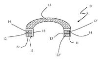
도 1은 본 발명에 따른 리시버 튜브용 게터 시스템을 위에서 본 개략도를 도시하고 있다.
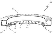
도 2는 도 1의 Ⅱ-Ⅱ 단면을 도시하고 있다.
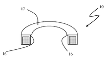
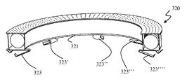
도 3은 도 1에 도시된 게터 시스템의 대안적 실시예를 도시하고 있다.
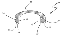
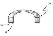
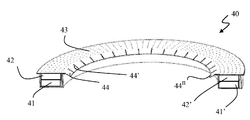
도 4 및 도 5는 두 가지 대안적인 게터 물질 필의 배치와 함께 도 2의 실시예의 단면도를 도시하고 있다.
도 6 및 도 7은 본 발명에 따른 리시버 튜브에서 게터 시스템의 중앙 관형 요소에 대한 고정 수단의 2개의 서로 다른 실시예를 도시하고 있다.
도 8a 및 도 8b는 다른 고정 수단의 실시예의 2개의 서로 다른 배치를 각각 도시하고 있다.
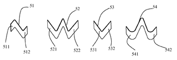
도 9는 게터 시스템 내에서 사용하기 위한 탄성 수단의 몇몇 가능한 실시예를 도시하고 있다.
도 10은 게터 물질 필과 접촉하고 있는 탄성 수단을 포함한 게터 시스템을 도시하고 있다.
도 11은 본 발명에 따른 게터 시스템의 대안적인 바람직한 실시예를 도시하고 있다.The present invention will be described in detail with reference to the following drawings.
1 shows a schematic view from above of a getter system for a receiver tube according to the invention.
FIG. 2 shows a II-II cross section of FIG. 1.
3 illustrates an alternative embodiment of the getter system shown in FIG. 1.
4 and 5 illustrate cross-sectional views of the embodiment of FIG. 2 with the placement of two alternative getter material fills.
6 and 7 show two different embodiments of fastening means for the central tubular element of the getter system in the receiver tube according to the invention.
8a and 8b respectively show two different arrangements of embodiments of different fastening means.
9 shows some possible embodiments of resilient means for use in the getter system.
10 shows a getter system including elastic means in contact with a getter material fill.
11 shows an alternative preferred embodiment of a getter system according to the present invention.
도면에서, 특히 비배타적으로 수용망의 메쉬 크기 또는 압축된 게터 물질 분말 필과 관련하여, 요소들의 치수와 치수 비율은 본 발명의 이해를 돕기 위해 변경될 수 있다. 또한, 예컨대, 리시버 튜브의 구성 요소와 아울러, 수용망의 납땜 지점 또는 구속부와 같이 선택적으로 존재하는 요소들은 발명을 이해하는 데 필수적인 것이 아니므로 도시되어 있지 않다. In the drawings, in particular with respect to the mesh size of the receiving network or the compressed getter material powder fill, the dimensions and dimensional ratios of the elements can be changed to aid the understanding of the present invention. Further, for example, components of the receiver tube, as well as elements that are optionally present, such as solder points or restraints in the receiving network, are not shown because they are not essential to the understanding of the invention.
태양열 집열기 리시버 튜브의 경우에서와 같이, 특히, 밀봉된 장치의 내부 용적으로부터 수소를 제거하기 위해 사용될 때, 압축된 분말 필의 형태로 사용되는 게터 물질이 갖는 문제점 중 하나는, 수소화물 형성으로 인한 필 구조의 취화 현상을 동반하는 상당한 수준의 수소가 흡수됨으로 인한 팽윤 현상과 관련이 있다. 이러한 현상들의 발생과 강도는 가스 부하에 의해 결정되기 때문에, 사전에 쉽게 예측할 수 없다. 게터 물질 필의 용량이 소진되기 전에도, 상술한 현상은 점진적인 필의 분해를 초래하고, 그로 인해, 게터 물질 분말이 발생하게 된다는 문제점이 관찰되었다. One problem with getter materials used in the form of compacted powder fills, especially when used to remove hydrogen from the internal volume of a sealed device, as in the case of solar collector receiver tubes, is due to hydride formation It is associated with swelling due to the absorption of significant levels of hydrogen with the brittleness of the peel structure. Since the occurrence and intensity of these phenomena are determined by the gas load, they cannot be easily predicted in advance. Even before the capacity of the getter material fill was exhausted, it was observed that the above-mentioned phenomenon caused a gradual decomposition of the fill, resulting in the generation of getter material powder.
태양열 집열기 리시버 튜브에 채용되는 몇몇 게터 시스템은 분말을 유지하기 위한 수단을 구상하고 있으나, 통상적으로, 이 수단들은, 예컨대, 하우징 지지체 내에 필을 배치함으로써, 분리된 분말의 일부를 유지하는 치수를 갖는다. 이러한 수단은, 필이 분해되어 과다한 분말이 발생하는 경우, 효과적이지 않다. 특히, 망 구조가 사용되는 경우, 필 구조로부터 분리될 수 있는 모든 분말 입도를 유지할 수 있을 정도로 메쉬가 충분히 조밀하다면, 메쉬가 (영어로 "clogging"이라 하는) 막히는 현상이 발생함으로써, 그 내부에 존재하는 게터 물질 용량이 소진되기 전에 가스를 제거하는 게터 시스템 용량을 손상시킬 수 있다. 반면에, 메쉬가 가장 큰 입도를 가진 분말만을 유지하는 치수를 갖는다면, 미세한 분말이 용기 내부에서 분산될 것이고, 이에 따라, 다른 유형의 문제를 발생시킬 수 있으며, 특히, 외부 관형 요소의 내면의 투과도 손실이 가장 명백하고 유해한 문제가 된다. Some getter systems employed in solar collector receiver tubes envision means for retaining powder, but typically these means have dimensions to retain a portion of the separated powder, for example by placing a fill in the housing support. . This means is not effective when the peel is decomposed and excessive powder is generated. In particular, when a network structure is used, if the mesh is dense enough to maintain all powder particle sizes that can be separated from the fill structure, the mesh may become clogged (called “clogging”), thereby creating It may damage the getter system capacity to degas before the existing getter material capacity is exhausted. On the other hand, if the mesh has dimensions that retain only the powder with the largest particle size, the fine powder will disperse inside the container, which may lead to other types of problems, in particular of the inner surface of the outer tubular element. Loss of permeability is the most obvious and detrimental problem.
후자의 유형의 해법이 분말 밀폐 문제를 취급하고 있는 국제 특허 출원 공개 번호 제 WO2010/144930 호에 개시되어 있으며, 이 특허 출원의 주요한 바람직한 실시예에서는 분말 형태의 게터 물질의 사용에 대해 고려하고 있으나, 분말 발생을 회피하는 방안을 다루지는 않고 있다. 상술한 제 WO2011/039281 호에서도 유사한 고려가 이루어졌으나, 이 특허 출원도 환형 형태를 가진 용기의 사용으로 인해 파생되는 가능성과 장점을 개시하거나 기재하고 있지는 않다. The latter type of solution is disclosed in International Patent Application Publication No. WO2010 / 144930, which deals with the problem of powder closure, and the main preferred embodiment of this patent application contemplates the use of getter materials in powder form. It does not address how to avoid powder generation. Similar considerations have been made in the above-mentioned WO2011 / 039281, but this patent application does not disclose or describe the possibilities and advantages derived from the use of a container having an annular form.
본 발명자들은, 공지의 기술과는 다르게, 실질적으로 환형 형상을 가진 지지체를 구비한 게터 시스템의 사용이 다양한 장점, 특히, 태양열 집열기에서의 장착의 용이성, 고정구에 대하여 상기 형태로 인해 제공되는 높은 유연성, 및 게터 시스템의 최소 구조적 변경을 채택함으로써 서로 다른 유형의 리시버 튜브(용융 염 또는 투열성 오일)에 대해 동일한 해법의 조정 가능성을 제공한다는 것을 밝혀내었다. The inventors have found that, unlike the known art, the use of a getter system with a support having a substantially annular shape provides a number of advantages, in particular the ease of mounting in a solar collector, the high flexibility afforded by the shape relative to the fixture. It has been found that by adopting minimal structural modifications of the, and getter systems, it offers the possibility of adjusting the same solution for different types of receiver tubes (molten salts or diathermy oils).
또한, 실질적으로 환형 형태를 가진 게터 시스템은 제조 공정 중에 발견된 결함으로 인한 재처리의 필요성 또는 리시버 튜브의 폐기와 관련된 이차적인 장점을 또한 나타낸다. 사실상, 두 가지 경우 모두에서, 게터 시스템을 복원할 필요가 있다. 공지의 기술에 따라 제조된, 즉, 선형 형태를 갖고(예컨대, 슬레지) 중앙 튜브에 납땜된 표준 게터 시스템은, 리시버 튜브로부터 제거될 때 그 구조나 기능적 특성을 완전하게 유지함으로써, 복원되기 어렵다. 이러한 공지의 시스템은, 소진된 리시버 튜브를 폐기하는 작업을 할 때, 환경적 영향과 안전상의 이유로 적당한 흡입 시스템을 이용하여 수집하여야 하는 게터 물질 분말을 발생시킨다. 다른 한편으로, 리시버 튜브 재처리의 경우, 게터 시스템에 대한 돌이킬 수 없는 손상의 위험과, 소진된 튜브의 경우에서보다는 심하지 않지만, 어떤 경우, 분말 발생 현상이 나타날 위험이 모두 있다. 한편, 실질적으로 환형 형태를 가진 시스템은 게터 시스템을 손상시키지 않고 복원할 수 있도록 하며, 상기 시스템은 소진된 튜브의 경우에 보다 쉽게 배치되거나, 재처리된 튜브의 경우에 보다 쉽게 다시 채용될 수 있다. In addition, the getter system having a substantially annular shape also exhibits a secondary advantage associated with the disposal of the receiver tube or the need for reprocessing due to defects found during the manufacturing process. In fact, in both cases, there is a need to restore the getter system. Standard getter systems made according to known techniques, ie, having a linear form (eg, a sledge) and soldered to a central tube, are difficult to recover by maintaining their structural or functional properties completely when removed from the receiver tube. Such known systems generate getter material powder that must be collected using a suitable suction system for environmental impact and safety reasons when working to dispose of exhausted receiver tubes. On the other hand, in the case of receiver tube reprocessing, there is both the risk of irreversible damage to the getter system and, in some cases, less severe than in the case of exhausted tubes, but in some cases, the risk of powder development. On the other hand, a system with a substantially annular shape allows restoration without damaging the getter system, which can be more easily deployed in the case of exhausted tubes or more easily re-employed in the case of reprocessed tubes. .
또한, 이하에서 후술하는 바와 같이, 실질적으로 환형 형태는 게터 시스템 내부에서 정확한 게터 물질의 온도와 관련된 문제점을 보다 효율적으로 해결할 수 있도록 한다. In addition, as described below, the substantially annular shape allows for more efficient solution of problems associated with the temperature of the correct getter material inside the getter system.
본 발명에 따른 게터 물질 지지체의 제 1 실시예가 위에서 본 개략도인 도 1과 Ⅱ-Ⅱ 축을 따라 취한 단면도인 도 2에 도시되어 있다. 게터 시스템(10)의 금속 용기는 실질적으로 환형 형상을 가지며, 베이스(11) 위에는 게터 물질 필(12, 12', 12")이 배치되어 있다. 베이스(11)는 고체이고, 환상면 높이, 즉, 용기의 내벽(13)과 외벽(14)을 형성하는 부분도 고체이며, 상기 용기는 적당한 수용 수단(15)에 의해 상부가 밀폐되며, 도 1 및 도 2에 도시된 것들과 같이 가장 일반적인 경우에, 상기 수용 수단은 게터 물질 필로부터 분리될 가능성이 있는 분말을 수용하기 위한 금속망을 포함한다. 상기 금속망은 통상적으로 0.05㎜ 내지 0.2㎜의 개구를 가진 홀을 갖는다. 도 2의 단면은 상기 용기가 쌍(12, 22 및 12', 22')으로 표시된 필들의 더 많이 중첩된 열들을 수용할 수 있음을 나타내고 있다. A first embodiment of a getter material support according to the invention is shown in FIG. 2, which is a schematic view from above, and in cross section taken along the II-II axis. The metal container of the
원형 홀인 경우, 상술한 값들은 홀의 직경이거나, 망의 개구의 최대 치수를 의미한다. In the case of a circular hole, the above-mentioned values mean the diameter of the hole or the maximum dimension of the opening of the network.
대안적인 등가의 실시예는 수용 수단으로서, 금속망이나 그와 동등한 다공질 격막이 구비되어 있는 개구를 가진 밀폐된 금속 스트립이나, 완전히 폐쇄되어 있기는 하지만 그 폭이 베이스(11)의 폭이나 그와 동등한 벽(13, 14)들 사이의 거리에 의해 형성되는 환상면 코로나(toroid corona)에 비해 넓은 금속 스트립을 구상하고 있다. 이러한 후자의 유형이 Ⅱ-Ⅱ 축을 따라 취한 개략 단면도인 도 3에 구현되어 도시되어 있다. 이 경우에서, 용기의 원주를 따라 연장하는 슬릿(16)이 수용 수단(17)과 용기의 하나의 벽, 보다 구체적으로는, 내벽(13) 사이에 배열된다. 슬릿(16)의 폭은, 필로부터 분리되는 게터 물질 분말을 유지함과 동시에 게터 물질이 리시버 튜브의 내부 분위기로부터 특히 수소와 관련된 가스 종을 제거할 수 있도록, 0.05㎜ 내지 0.2㎜로 구성된다. An alternative equivalent embodiment is an enclosed metal strip having an opening provided with a metal mesh or equivalent porous diaphragm, as an accommodating means, but the width of the base 11 or its width, although completely closed. It envisions a wider metal strip compared to the toroid corona formed by the distance between the
게터 시스템의 기능을 손상시키지 않도록 하기 위해, 본질적으로, 환형 용기 단면의 폭(즉, 도 1 내지 도 3에서 이미 예시한 바와 같이, 측방향 벽(13, 14)들 사이의 거리)이, 즉, 환상면 코로나 폭의 관점에서, 게터 물질 필의 측방향 인컴브런스보다 약간 넓은, 게터 물질 필을 수용하는 실질적으로 환형 형태를 가진 게터 시스템을 수용한 태양열 집열기 리시버 튜브를 채용함으로써, 본 발명에 개시된 해법이 분말의 형성을 가능한 한 많이 늦출 수 있도록, 게터 물질 필은 반드시 분말의 일부를 과다하게 소실하지 않아야 한다. 특히, 용기의 단면 폭은 1.05*i 내지 1.2*i로 구성되며, 상기 i는 상기 게터 물질 필의 전체 측방향 인컴브런스(이는 보다 정렬된 열들을 가질 수 있는 가능성을 고려하고 있다)이다. 용기의 단면이 과다하게 좁으면, 필 구조가 팽윤됨으로 인하여 필 구조에 응력이 발생하게 될 것인 반면, 단면이 과다하게 넓으면, 태양열 집열기에 대한 게터 시스템의 적재 또는 설치시 용기 벽과 충돌하여 필이 파손됨으로써 분말이 발생함과 아울러 분말원의 개수가 증가하게 될 가능성이 있으며, 용기의 과도한 인컴브런스로 이어질 것이다. In order not to impair the function of the getter system, essentially, the width of the annular vessel cross section (ie the distance between the
"신선한" 게터 시스템, 즉, 새로 활성화된 시스템 또는 의미 있는 H2 부하에 아직 노출되지 않은 시스템으로는 쉽게 관찰할 수 없는 현상을 고려하여야 하기 때문에, 이러한 폭 값의 결정은 결코 간단하지 않다. 이러한 현상은, 10년 이상이어야 하는 장치의 예상 수명과 입자 손실과 관련된 특수한 응용 요건을 또한 고려하여, 시스템이 상당량의 수소를 흡수한 후에만 관찰할 수 있다. Determining this width value is by no means simple, since one must take into account phenomena that are not readily observable with "fresh" getter systems, i.e. newly activated systems or systems that have not yet been exposed to a significant H 2 load. This phenomenon can only be observed after the system has absorbed a significant amount of hydrogen, also taking into account the specific life requirements of the device, which should be more than 10 years, and the specific application requirements associated with particle loss.
기본적으로, 용기 내부에 필을 배치하는 세 가지의 방법이 있다. 제 1 방법이 도 1에 도시되어 있으며, 필들이 용기의 베이스(11) 상에 수평으로 배치되고, 즉, 게터 물질 (원통형) 필의 축이 환형 용기의 축에 대해 실질적으로 평행하게 배치된다. 이 경우, 모든 필들이 동일한 직경을 갖는다고 가정하면, 측방향 인컴브런스(i)는 게터 물질 필(12, 12', 12")의 직경(d)과 실질적으로 일치한다. Basically, there are three ways to place the fill inside the container. The first method is shown in FIG. 1, wherein the pills are arranged horizontally on the
전술한 바와 같이, 이 경우, 필(12, 12')들을 포함하는 제 1 층과 필(22, 22')들을 포함하는 제 2 층으로서 중첩된 필들의 2개 층이 존재하는 것으로 도 2에 예시된 바와 같이, 게터 물질 필들의 더 많은 열을 겹쳐서 배열하는 것도 가능하다. As described above, in this case there are two layers of overlapping pillars as a first layer comprising the
특히, 도 1 및 도 2에 도시된 바와 같이, 채워지지 않아서 팽윤된 필에 대해 작은 힘을 가하기는 하지만, 용기를 밀폐하고 있는 상부(15)도 수소 수착으로 인한 제어되지 않은 분말 발생 현상을 초래할 수 있으므로, 용기 높이도 원통형 필의 높이(h)와 중첩된 필 층의 개수(n)에 따라 결정되는 것이 바람직하다. 특히, 용기 높이는 n*h*1.05 내지 n*h*1.2로 구성되는 것이 유리하다. In particular, as shown in FIGS. 1 and 2, although a small force is applied to the unfilled and swelled fill, the top 15, which seals the container, may also cause uncontrolled powder generation due to hydrogen sorption. As such, the container height is also preferably determined in accordance with the height h of the cylindrical fill and the number n of fill layers superimposed. In particular, the container height is advantageously comprised of n * h * 1.05 to n * h * 1.2.
도 4는 본 발명에 따른 환형 용기(20)의 단면도를 도시하고 있으나, 여기서는 원통형 필(22, 22')이 수직으로 배치되고, 그들의 축이 용기의 축과 실질적으로 직교하며, 교차하지는 않는다. 4 shows a cross-sectional view of the
이러한 유형의 배열에서, 모든 필들이 동일한 직경(d)을 갖는 경우, 측방향 인컴브런스(i)는 게터 물질 필의 직경에 의해 주어진다. 이 경우, 바람직한 실시예는 1.05*d 내지 1.2*d로 구성된 높이를 가진 용기를 구상하고 있다. In this type of arrangement, when all the pills have the same diameter d, the lateral incomb i is given by the diameter of the getter material fill. In this case, the preferred embodiment envisions a container having a height comprised of 1.05 * d to 1.2 * d.
도 4는 천공된 메쉬로 이루어진 봉입체(25)를 도시하고 있으나, 비한정적인 예로서 도 3에 도시된 유형, 즉, 게터 시스템의 환형 용기 에지를 따라 슬릿(16)이 연장하도록 된 중실 스트립(17)과 같이, 기능적 관점에서 완전히 동일한(즉, 가스를 제거하는 게터 물질에 대한 접근이 가능하고 분말을 유지하는 작용을 하는) 다른 용기용 밀폐 요소를 채용할 수 있다. FIG. 4 shows an
마찬가지로, 도 5는 전술한 유형의 용기(30)를 도시하고 있으며, 이 용기는 수직으로 배치된 게터 물질 필(32, 33)의 열을 포함하고 있으며, 필들의 축은 용기의 축과 실질적으로 직교하지만, 이 경우에, 필들의 축은 용기의 축과 교차한다. 이러한 배치에서, 필들이 동일한 높이(h)를 갖는 경우, 측방향 인컴브런스(i)는 용기의 측방향 벽들 사이에 1열로 나란히 배열된 필들의 개수와 높이(h)의 곱에 의해 주어진다. Likewise, FIG. 5 shows a
투열성 오일을 사용하는 리시버 튜브의 경우에서 특히 유용한 다른 바람직한 실시예에서, 용기는 서로 다른 방사율(ε)을 나타내는 2개 이상의 서로 다른 물질로 제조된 부분들로 형성된다. 특히, 용기는 ε≥0.8을 의미하는 고방사율을 가진 물질과 함께 ε≤0.2를 의미하는 저방사율을 가진 물질로 제조되며, 상기 저방사율의 물질은 리시버 튜브의 영역을 향하고 있는 용기의 부분 또는 구성 요소, 즉, 예컨대, 도 1을 참조하면, 외벽(14)과 같이 중앙 튜브를 향하고 있지 않은 부분을 최저 온도로 만들기 위해 채용된다. 동일한 이유로, 내벽(13)은 고방사율의 물질로 제조되는 것이 유리하다. 그러나, 이러한 유형의 해법은, 외부 관형 요소를 향하고 있는 부분인, 게터 물질 필을 수용하고 있는 슬레지의 부분에 저방사율의 물질을 사용함으로써, 미국 특허 제 6,832,608 호에 개시된 바와 같은 다른 형태를 가진 태양열 집열기 리시버 튜브에서도 유리하게 사용될 수 있다. In another preferred embodiment which is particularly useful in the case of receiver tubes using diathermy oils, the container is formed from portions made of two or more different materials exhibiting different emissivity ε. In particular, the container is made of a material having a low emissivity meaning ε ≤ 0.2 together with a material having a high emissivity meaning ε ≥ 0.8, the low emissivity material being a part or composition of the container facing the area of the receiver tube. Referring to the element, ie, for example with reference to FIG. 1, it is employed to bring the minimum temperature, such as the
리시버 튜브 내부에 게터 시스템을 고정할 수 있는 다양한 방법들이 존재하며, 특히, 중앙 튜브에 대해 용기를 구속하기 위해 탄성 고정 수단을 구비한 실질적으로 환형 금속 구조물을 사용하는 것이 특히 유리하다. There are various ways of securing the getter system inside the receiver tube, and it is particularly advantageous to use a substantially annular metal structure with elastic fixing means to restrain the container with respect to the central tube.
효과적인 고정을 위해, 상기 고정 수단은 3개 이상이어야 하며, 중앙 튜브에 대해 부하를 잘 분배하기 위해 서로 등간격으로 이격되는 것이 바람직하다. 또한, 상기 고정 수단은 가요성이 있으며, 즉, 리시버 튜브의 중앙 관형 요소에 대해 용기를 구속하기 위해 변형될 수 있는 것이 바람직하다. 용어 "가요성"은 탄성 요소, 즉, 중앙 관형 요소로부터 용기가 제거되면 자신의 형상으로 복귀할 수 있는 요소와 아울러, 장착 작업의 결과로서 비가역적으로 변형되는 요소를 모두 의미한다. For effective fixation, the fixing means should be at least three, preferably equally spaced from one another in order to distribute the load well with respect to the center tube. It is also preferred that the fastening means is flexible, ie can be deformed to restrain the container with respect to the central tubular element of the receiver tube. The term "flexible" means both elastic elements, ie elements that can return to their shape when the container is removed from the central tubular element, as well as elements that are irreversibly deformed as a result of the mounting operation.
가능한 두 가지 실시예가 도 6 및 도 7에 도시되어 있다. 도 6은 수직으로 배치된 게터 물질 필(312, 312')을 수용하고 있는 본 발명에 따른 게터 시스템(310)의 단면도를 도시하고 있다. 후크 형태의 탄성 고정 요소(313, 313', 313")가 용기(310)의 베이스(311)에 고정되어 있다. 도 6의 실시예에 따라 제조된 게터 시스템은 4개의 고정점을 가지며, 그 중 3개의 고정점이 도면에 도시되어 있다. Two possible embodiments are shown in FIGS. 6 and 7. 6 illustrates a cross-sectional view of a
대안적이며 완전히 동등한 실시예가 도 7에 도시되어 있으며, 여기에서는, 게터 시스템(320)의 베이스(321)가 8개의 고정 수단을 갖고, 그 중 5개의 고정 수단(323, 323', 323", 323''', 323'''')이 금속성의 변형가능한 스트립의 형태로 도면에 도시되어 있다. An alternative and completely equivalent embodiment is shown in FIG. 7, where the
실용성과 효율성 면에서, 용기에 고정 수단을 고정하는 바람직한 방법은 납땜하는 것이다. In terms of practicality and efficiency, the preferred method of securing the fixing means to the container is to solder.
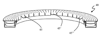
대안적이며 특히 유리한 해법이 도 8a 및 도 8b에 도시되어 있으며, 여기에서는, 게터 시스템(40)이 수평으로 배치된 2개의 게터 물질 필 층(41, 41', 42, 42')들을 수용하고 있다(이는 필들이 수직으로 배치된 경우에도 완전히 동등하다). 용기의 천공된 커버(43)가 내부를 향하여 연장되고, 복수의 금속 핀(fin)(44, 44', 44n)을 형성하는 실질적으로 방사상 절개부를 제공한다. 이 경우, 휘어지지 않은 모든 핀들은 도 8b에 도시된 바와 같이 중앙 관형 요소에 대한 고정 수단이 될 것이며, 도 8b에서는 휘어지지 않은 핀(45, 45', 45")들이 리시버 튜브의 중앙 관형 요소에 대해 환형 게터 시스템을 고정하는 고정 수단이 된다. An alternative and particularly advantageous solution is shown in FIGS. 8A and 8B, where the
특정 실시예에서, 상기 고정 수단은 우수한 열전도율, 즉, 50 W/m℃ 이상의 열전도율을 제공한다. 이러한 유형의 해법은, 냉각 유체로서 투열성 오일을 사용하는 것과 같은 중간 작동 온도의 태양열 집열기 리시버 튜브가 채용되는 경우, 특히 유리하다. In a particular embodiment, the fixing means provides excellent thermal conductivity, ie, thermal conductivity of at least 50 W / m ° C. This type of solution is particularly advantageous when a solar collector receiver tube of medium operating temperature is employed, such as using a diluent oil as the cooling fluid.
그러나, 다른 실시예는 낮은 열전도율, 즉, 20 W/m℃ 이하의 열전도율을 가진 고정 수단의 사용을 구상한다. 이러한 유형의 해법은, 용융 염 리시브 튜브와 같은 높은 작동 온도의 태양열 집열기 리시버 튜브에서, 유리하다. However, another embodiment envisions the use of fastening means having a low thermal conductivity, ie, a thermal conductivity of 20 W / m ° C. or less. This type of solution is advantageous in high operating temperature solar collector receiver tubes such as molten salt receive tubes.
게터 시스템의 실질적으로 환형 용기에는 고정력을 향상시키기 위해 추가적인 고정 수단, 예컨대, 플랜트의 리시브 튜브의 설치 및 장착 단계에서 유용한 수단이 제공될 수 있음을 유의하여야 한다. 이러한 추가적인 고정 수단은, 통상적으로, 서로 다른 열팽창을 보상하기 위해 가변적인 길이를 가진 요소 또는 외부 관형 요소와 인터페이싱함으로써, 중앙 관형 요소와 관련된 다양한 요소들에 대해 게터 시스템 용기를 구속한다. It should be noted that the substantially annular container of the getter system may be provided with additional securing means, for example, useful means in the installation and mounting of the receiving tube of the plant. Such additional fastening means typically constrain the getter system container to the various elements associated with the central tubular element by interfacing with elements of varying length or outer tubular elements to compensate for different thermal expansion.
본 발명에 따른 시스템의 다른 개선은 게터 물질 필과 직접 접촉하도록 용기 내부에서 하나 이상의 탄성 요소를 유리하게 사용하는 것을 구상한다. Another refinement of the system according to the invention envisages the advantageous use of one or more elastic elements inside the container in direct contact with the getter material fill.
이러한 탄성 요소의 주요 기능은, 필들을 서로에 대해 가압함으로써, 필들에 대해 압축력을 가하는 것이다. 이는, 전술한 바와 같이, 자신들의 치수에 비해 약간 큰 실질적으로 환형 용기 내에 수용된 필들이 탄성 요소가 가하는 압축력에 의해 구속될 수 있도록 보장한다. The main function of this elastic element is to apply a compressive force to the pillars by pressing the pillars against each other. This ensures that, as described above, the pills contained in the substantially annular container, which are slightly larger than their dimensions, can be constrained by the compressive force exerted by the elastic element.
또한, 탄성 요소는 용기 내부에 게터 물질이 없는 영역을 생성한다. 따라서, 이러한 탄성 요소들은 압축될 수 있으므로, 수소 수착으로 인한 게터 물질 필의 용적 증가를 보상할 수 있으며, 이에 따라, 필 내부 응력으로 인한 분말 발생 현상을 더 줄일 수 있다. 탄성 요소에 의해 가해지는 힘은, 용기 내부에서 게터 물질 필의 우수한 구획 작용을 보장함과 동시에, 자신이 압축됨으로써 H2 수착으로 인한 게터 물질 필의 용적 팽창을 보상할 수 있도록, 50 내지 150N으로 구성되는 것이 유리하다. 이러한 탄성력의 값을 결정하는 것은 극히 중요한 데, 그 이유는 과다한 압축이 필의 파손을 초래할 것이기 때문이며, 수소 수착으로 인한 취화에 의해 필 저항이 시간에 따라 변하는 것을 고려하여야 하기 때문에, 매우 용이하지 않다. The elastic element also creates an area free of getter material inside the container. Thus, these elastic elements can be compressed, thereby compensating for the increase in volume of the getter material fill due to hydrogen sorption, thereby further reducing powdering phenomena due to internal stress in the fill. The force exerted by the elastic element is reduced to 50 to 150 N to ensure good partitioning of the getter material fill within the container, while at the same time compressing itself to compensate for the volumetric expansion of the getter material fill due to H 2 sorption. It is advantageous to be constructed. Determining the value of this elastic force is extremely important, because excessive compression will result in breakage of the peel, which is not very easy because it is necessary to take into account that the peel resistance changes with time due to embrittlement due to hydrogen sorption. .
또한, 탄성 요소는 분말이 쉽게 발생 지점을 회피하기 위해 필과의 접촉 영역에 에지가 없어야 하며, 이에 따라, 탄성 요소는 평탄하거나 라운드진 것이 유리하다. 이러한 특징을 이하에서는 "분산 접촉"이라 한다. 도 9는 본 발명에 따른 태양열 집열기 리시버 튜브의 게터 시스템에 채용되기에 적합한 탄성 요소(51, 52, 53, 54)의 몇몇 예를 도시하고 있다. 필 표면과 분산 접촉할 수 있도록, 게터 물질 필과 접촉하여야 하는 부분(511, 512, 521, 522, 531, 532, 541, 542)들이 평탄하거나 라운드진 것을 관찰할 수 있다. In addition, the elastic element should be free of edges in the area of contact with the fill in order to easily avoid the point where the powder occurs, whereby the elastic element is advantageously flat or rounded. This feature is hereinafter referred to as "distributed contact". 9 shows some examples of
도 10은 도 8b에 도시된 것과 유사한 게터 시스템(60)을 도시하고 있으며, 여기에서는, 탄성 요소(61, 61', 61")들이 용기 내부에 존재하고 있다. FIG. 10 shows a
물론, 이러한 유형의 해법은 전술한 실질적으로 환형 형태를 가진 가능한 임의의 게터 시스템에도 적용될 수 있다. 고정 수단이 도 6 및 도 7에 도시된 요소(313 또는 323)와 유사한 후크일 수 있음과 아울러, 특정 실시예가 커버 상의 핀과 용기의 베이스에 고정된 후크 또는 탄성 고정 수단 모두의 존재를 예상하여 가능한 한 많이 분산되는 힘을 중앙 관형 요소에 가하는 고정부를 갖도록, 예컨대, 게터 물질 필들이 수평으로 배치되는 대신 2개의 중첩된 열들로 수직으로 배치될 수 있다. Of course, this type of solution can be applied to any possible getter system with the substantially annular form described above. While the fastening means may be hooks similar to the
탄성 요소들은 용기의 일부에 게터 물질이 없도록 하기 위해 사용될 수도 있으며, 그러한 경우에는, 탄성 요소들의 말단부만이 상술한 기하학적(분산 접촉) 및 탄성적 특성을 나타내면 된다. Elastic elements may be used to ensure that no part of the container is getter material, in which case only the distal ends of the elastic elements need to exhibit the geometric (distributed contact) and elastic properties described above.
탄성 요소들이 용기의 일부에 게터 물질이 없도록 하기 위해 사용되는 경우, 게터 물질이 가용 용적의 40% 내지 80%를 점유하는 것이 유용하다. When elastic elements are used to ensure that part of the container is free of getter material, it is useful for the getter material to occupy 40% to 80% of the available volume.
마지막으로, 특히 유리할 수 있는 마지막 실시예가 도 11에 도시되어 있다. 이 경우에서, 게터 시스템(110)은 베이스(111) 상에 수직으로 배치된 일련의 게터 필(112, 122')을 수용하고 있다. 게터 시스템의 상부는 천공된 커버(113)로 제조된다. 베이스(111)는 일련의 핀(114, 114', 114")을 제공하며, 태양열 집열기의 특수한 유형 및 구조에 따라 핀들 중 일부는 휘어지거나, 자신들의 열전도율로 인해 게터 물질의 온도를 높이는 수단과 아울러 고정 수단이 되도록 남아 있을 수 있다. Finally, a last embodiment which can be particularly advantageous is shown in FIG. 11. In this case, the
마지막 양태에서, 본 발명은 실질적으로 반(半) 환형 형상을 가지며 서로 커플링되는 2개의 요소들로 구성된 용기를 포함하는 태양열 집열기 리시버 튜브에 관한 것이다. 2개의 반(半) 환상면들을 커플링하기 위해 가장 유용한 방법은 이들의 극단에 배치된 탄성 수단, 예컨대, 스프링을 이용하는 것이다. 실용적이지 않을지라도, 예컨대, 반 환상면들의 극단을 납땜하는 것과 같은 다른 해법이 채용될 수도 있으나, 이 시스템은 설치가 용이하기 때문에 특히 유리하다. 이러한 유형의 해법은 리시버 튜브 내에서 게터 시스템의 설치 과정을 간소화한다. In a final aspect, the invention relates to a solar collector receiver tube comprising a container consisting of two elements having a substantially semi-annular shape and coupled to each other. The most useful method for coupling two semi-annular surfaces is to use elastic means, for example springs, arranged at their extremes. Although not practical, other solutions may be employed, for example soldering the extremes of the semi-annular surfaces, but this system is particularly advantageous because it is easy to install. This type of solution simplifies the installation process of the getter system in the receiver tube.
또한, 리시버 튜브 내에서 게터 시스템의 설치 과정을 간소화하기 위한 다른 실시예는, 하나 이상의 지점에서 중단되는, 즉, 환형 형상 자체가 폐쇄되지 않고 서로 마주하는 2개 이상의 폐쇄된 극단을 나타내는, 실질적으로 환형 형상을 가진 용기의 사용을 예상한다. 상기 용기는 탄성적 특성이 우수한 금속성 물질로 제조되며, 폐쇄된 용기 극단에 탄성 견인 시스템을 구비한다. Further, another embodiment for simplifying the installation process of the getter system in the receiver tube is substantially at least one point, that is, the annular shape itself exhibits two or more closed extremes facing each other without being closed. Expect the use of a container having an annular shape. The container is made of a metallic material with excellent elastic properties and has an elastic traction system at the closed container extreme.
마지막으로, 게터 물질과 관련하여, 고온에서 사용되는 경우에도 수소 수착 특성이 우수한 게터 물질이 바람직하다. 이러한 이유로, 바람직한 게터 물질은, 예컨대, 미국 특허 제 3,203,901 호(Zr-Al 합금), 미국 특허 제 4,306,887 호(Zr-Fe 합금), 영국 특허 제 2,077,487 호(Zr-V-Fe 합금), 미국 특허 제 5,961,750 호(Zr-Co-희토류 합금)에 개시된 게터 물질들이다. 특히, 고온에서의 수소 수착을 위해, 예컨대, 국제 특허 출원 공개 번호 제 WO2007/148362 호 및 제 WO2007/099575 호와 아울러 국제 특허 출원 공개 번호 제 WO2010/105945 호에 개시된 이트륨계 합금의 사용이 또한 공지되어 있다. 이들은 바람직한 게터 합금이지만, 본 명세서에 개시된 본 발명의 개념과 함께 임의의 수소 게터 물질이 채용될 수도 있다. Finally, with regard to the getter material, a getter material that is excellent in hydrogen sorption properties even when used at high temperatures is preferred. For this reason, preferred getter materials are, for example, US Pat. No. 3,203,901 (Zr-Al alloy), US Pat. No. 4,306,887 (Zr-Fe alloy), UK Pat. No. 2,077,487 (Zr-V-Fe alloy), US Pat. Getter materials disclosed in US Pat. No. 5,961,750 (Zr-Co-rare earth alloy). In particular, for the hydrogen sorption at high temperatures, the use of the yttrium-based alloys disclosed in, for example, International Patent Application Publication Nos. WO2007 / 148362 and WO2007 / 099575, as well as International Patent Application Publication No. WO2010 / 105945, are also known. It is. These are preferred getter alloys, but any hydrogen getter material may be employed in conjunction with the inventive concepts disclosed herein.
Claims (21)
상기 용기는 실질적으로 환형 형상을 가지며, 상기 용기는 상기 중앙 관형 요소 주위에 배열되고, 상기 용기의 단면은 1.05*i 내지 1.2*i로 구성된 폭을 가지며, 상기 i는 상기 원통형 게터 물질 필의 측방향 전체 치수인 것을 특징으로 하는,
태양열 집열기 리시버 튜브. One or more central tubular elements arranged in the outer tubular element, one or more elements of varying length to compensate for the different thermal expansion of the two tubular elements, and a cylindrical getter material compressed powder fill 12, 12 ', 12 " One or more getter systems (10; 20) including a container for holding 22, 22 '; 32, 33; 312, 312'; 322, 322 '; 41, 41'; 42, 42 '; 112, 112'; A solar collector receiver tube comprising: 30; 310; 320; 40; 60; 110,
The vessel has a substantially annular shape, the vessel is arranged around the central tubular element, the cross section of the vessel has a width consisting of 1.05 * i to 1.2 * i, and i is the side of the cylindrical getter material fill It is direction overall dimension,
Solar collector receiver tube.
상기 원통형 게터 물질 필들은 자신들의 축이 상기 용기의 축과 실질적으로 직교하도록 배열되고, 상기 용기의 높이는 1.05*d 내지 1.2*d로 구성되며, 상기 d는 상기 원통형 게터 물질 필의 직경인,
태양열 집열기 리시버 튜브. The method of claim 1,
The cylindrical getter material fills are arranged such that their axis is substantially orthogonal to the axis of the container, the height of the container consists of 1.05 * d to 1.2 * d, wherein d is the diameter of the cylindrical getter material fill,
Solar collector receiver tube.
상기 원통형 게터 물질 필들은 자신들의 축이 상기 용기의 축에 대해 실질적으로 평행하도록 배열되는,
태양열 집열기 리시버 튜브. The method of claim 1,
The cylindrical getter material fields are arranged such that their axes are substantially parallel to the axis of the container.
Solar collector receiver tube.
상기 용기의 높이는 n*h*1.05 내지 n*h*1.2로 구성되며, 상기 h는 상기 원통형 게터 물질 필의 높이이고, 상기 n은 적층된 필 층의 개수인,
태양열 집열기 리시버 튜브. The method of claim 1,
The height of the vessel consists of n * h * 1.05 to n * h * 1.2, where h is the height of the cylindrical getter material fill and n is the number of stacked fill layers,
Solar collector receiver tube.
상기 용기의 상부(15, 43; 113)는 금속성 메쉬, 다공질 격막 및/또는 천공된 시트로부터 선택된 하나 이상의 천공된 요소를 포함하며, 이 천공된 요소의 홀들은 0.05㎜ 내지 0.2㎜로 구성된 개구를 구비하는,
태양열 집열기 리시버 튜브. The method of claim 1,
The tops 15, 43; 113 of the vessel comprise one or more perforated elements selected from metallic mesh, porous diaphragm and / or perforated sheet, the holes of the perforated elements having openings comprised of 0.05 mm to 0.2 mm. Equipped,
Solar collector receiver tube.
상기 용기의 상부는 0.05㎜ 내지 0.2㎜로 구성된 폭을 가진 슬릿(16)을 형성하는 밀폐된 금속성 부분(17)을 포함하는,
태양열 집열기 리시버 튜브. The method of claim 1,
The top of the container includes a closed metallic portion 17 forming a slit 16 having a width composed of 0.05 mm to 0.2 mm,
Solar collector receiver tube.
상기 용기는 0.2 이하의 방사율을 가진 물질로 제조된 부분과, 0.8 이상의 방사율을 가진 물질로 제조된 부분을 포함하며, 방사율이 낮은 상기 부분은 최저 온도가 되는 리시버 튜브의 영역에 의해 배열되는,
태양열 집열기 리시버 튜브. The method of claim 1,
The vessel comprises a portion made of a material having an emissivity of 0.2 or less, and a portion made of a material having an emissivity of 0.8 or more, wherein the portion having a low emissivity is arranged by a region of the receiver tube at the lowest temperature,
Solar collector receiver tube.
방사율이 낮은 상기 부분은 상기 용기의 외벽(14)을 포함하고/또는 방사율이 높은 상기 부분은 상기 용기의 내벽(13)을 포함하는,
태양열 집열기 리시버 튜브. The method of claim 7, wherein
The portion having low emissivity comprises the outer wall 14 of the container and / or the portion having high emissivity comprises the inner wall 13 of the container,
Solar collector receiver tube.
상기 용기는 상기 중앙 관형 요소의 3개 이상의 지점들에 당해 용기를 고정하기 위한 고정 수단(313, 313', 313"; 323, 323', 323", 323''', 323''''; 45, 45', 45")을 구비하는,
태양열 집열기 리시버 튜브. The method of claim 1,
The vessel may comprise securing means (313, 313 ', 313 "; 323, 323', 323", 323 ''',323''''for securing the vessel at three or more points of the central tubular element; 45, 45 ', 45 "),
Solar collector receiver tube.
상기 고정 수단들은 기본적으로 등간격으로 이격된,
태양열 집열기 리시버 튜브. The method of claim 9,
The fixing means are basically spaced at equal intervals,
Solar collector receiver tube.
상기 고정 수단들은 가요성인,
태양열 집열기 리시버 튜브. The method of claim 9,
The fastening means are flexible,
Solar collector receiver tube.
상기 고정 수단(45, 45', 45"; 114, 114', 114")은 금속 핀(44, 44',..., 44n)을 휘어서 얻어지는,
태양열 집열기 리시버 튜브. The method of claim 9,
The fixing means 45, 45 ', 45 "; 114, 114', 114" are obtained by bending metal pins 44, 44 ', ..., 44 n ,
Solar collector receiver tube.
상기 리시버 튜브의 작동 온도는 450℃ 이하이고, 상기 고정 수단은 50 W/m℃ 이상의 열전도율을 갖는,
태양열 집열기 리시버 튜브. The method of claim 9,
The operating temperature of the receiver tube is 450 ° C. or less, and the fixing means has a thermal conductivity of 50 W / m ° C. or more,
Solar collector receiver tube.
상기 리시버 튜브의 작동 온도는 450℃를 초과하고, 상기 고정 수단은 20 W/m℃ 이하의 열전도율을 갖는,
태양열 집열기 리시버 튜브. The method of claim 9,
The operating temperature of the receiver tube exceeds 450 ° C., and the fixing means has a thermal conductivity of 20 W / m ° C. or less,
Solar collector receiver tube.
상기 용기는 상기 리시버 튜브의 다른 구성 요소에 대해서도 상기 용기를 구속하기 위해 추가적인 고정 수단을 구비하는,
태양열 집열기 리시버 튜브. The method of claim 9,
Said container having further securing means for restraining said container with respect to other components of said receiver tube,
Solar collector receiver tube.
상기 구성 요소는 상기 외부 관형 요소 및/또는 상기 가변적인 길이를 가진 요소를 포함하는,
태양열 집열기 리시버 튜브. The method of claim 15,
The component comprises the outer tubular element and / or the variable length element,
Solar collector receiver tube.
상기 용기는 상기 원통형 게터 물질 필과 접촉하는 하나 이상의 탄성 요소(51, 52, 53, 54)를 포함하며, 상기 탄성 요소는 상기 원통형 게터 물질 필의 표면과 분산 접촉(511, 512; 521, 522; 531, 532; 541, 542)하는,
태양열 집열기 리시버 튜브. The method of claim 1,
The container includes one or more elastic elements 51, 52, 53, 54 in contact with the cylindrical getter material fill, the elastic elements dispersing contact with the surface of the cylindrical getter material fill (511, 512; 521, 522). 531, 532, 541, 542,
Solar collector receiver tube.
상기 용기의 내부 용적의 40% 내지 80%를 구성하는 비율에는 게터 물질이 존재하지 않으며, 상기 탄성 수단은 게터 물질이 존재하지 않는 부분을 결정하는,
태양열 집열기 리시버 튜브. The method of claim 17,
There is no getter material in the proportion constituting 40% to 80% of the interior volume of the container, and the elastic means determines the portion where no getter material is present,
Solar collector receiver tube.
상기 용기는 실질적으로 반환형 형상을 가진 2개의 서로 커플링된 요소들을 포하는,
태양열 집열기 리시버 튜브. The method of claim 1,
The container comprises two mutually coupled elements having a substantially returnable shape,
Solar collector receiver tube.
상기 커플링은 상기 실질적으로 반환형 형상을 가진 요소들의 극단에 배치된 탄성 수단에 의해 이루어지는,
태양열 집열기 리시버 튜브. The method of claim 19,
The coupling is made by elastic means disposed at the extreme of the substantially returnable shape,
Solar collector receiver tube.
상기 용기는 적어도 하나의 지점에서 중단되며, 서로를 향하고 있는 2개 이상의 폐쇄된 극단을 갖고, 견인 탄성 시스템이 상기 용기의 상기 폐쇄된 극단에 배열되는,
태양열 집열기 리시버 튜브. The method of claim 1,
The container is stopped at at least one point and has two or more closed extremes facing each other, and a traction resilient system is arranged at the closed extreme of the container,
Solar collector receiver tube.
Applications Claiming Priority (3)
| Application Number | Priority Date | Filing Date | Title |
|---|---|---|---|
| ITMI2011A001492 | 2011-08-04 | ||
| IT001492A ITMI20111492A1 (en) | 2011-08-04 | 2011-08-04 | IMPROVEMENTS FOR RECEIVER TUBES FOR SOLAR COLLECTORS |
| PCT/IB2012/053908 WO2013018033A1 (en) | 2011-08-04 | 2012-07-31 | Improvements for solar collectors receiver tubes |
Publications (1)
| Publication Number | Publication Date |
|---|---|
| KR20140050061A true KR20140050061A (en) | 2014-04-28 |
Family
ID=44584375
Family Applications (1)
| Application Number | Title | Priority Date | Filing Date |
|---|---|---|---|
| KR20147003874A KR20140050061A (en) | 2011-08-04 | 2012-07-31 | Improvements for solar collectors receiver tubes |
Country Status (9)
| Country | Link |
|---|---|
| US (1) | US9103565B2 (en) |
| EP (1) | EP2739915B1 (en) |
| JP (1) | JP5837981B2 (en) |
| KR (1) | KR20140050061A (en) |
| CN (1) | CN103717979B (en) |
| ES (1) | ES2544739T3 (en) |
| IL (1) | IL230721B (en) |
| IT (1) | ITMI20111492A1 (en) |
| WO (1) | WO2013018033A1 (en) |
Cited By (1)
| Publication number | Priority date | Publication date | Assignee | Title |
|---|---|---|---|---|
| KR20190052614A (en) | 2017-11-08 | 2019-05-16 | 김승수 | A fabrication method of composition contained unsaturated oils and arginine for suppressed odor |
Families Citing this family (10)
| Publication number | Priority date | Publication date | Assignee | Title |
|---|---|---|---|---|
| DE102009045100A1 (en) * | 2009-09-29 | 2011-04-07 | Schott Solar Ag | absorber tube |
| DE102009046064B4 (en) * | 2009-10-27 | 2014-03-06 | Schott Solar Ag | Absorber tube and method for reversibly loading and unloading a getter material |
| EP2325575A1 (en) * | 2010-04-22 | 2011-05-25 | SAES GETTERS S.p.A. | Improved getter system for hydrogen sensitve device |
| ITMI20120144A1 (en) * | 2012-02-03 | 2013-08-04 | Getters Spa | IMPROVEMENTS FOR TUBES RECEIVERS OF SOLAR COLLECTORS |
| ES2454775B1 (en) * | 2012-10-11 | 2015-03-10 | Abengoa Solar New Tech Sa | Vacuum tuning system in heat transfer tube |
| DE102013225077A1 (en) * | 2013-12-06 | 2015-06-11 | Continental Automotive Gmbh | Heat pipe with displacement bodies |
| JP6260409B2 (en) * | 2014-03-31 | 2018-01-17 | 株式会社豊田自動織機 | Method for manufacturing solar thermal collector |
| CN104713258B (en) * | 2015-03-11 | 2016-08-17 | 常州龙腾光热科技股份有限公司 | The getter device of solar vacuum heat-collecting pipe |
| JP2018076976A (en) * | 2016-11-07 | 2018-05-17 | 株式会社豊田自動織機 | Solar heat collection device |
| CN109489280B (en) * | 2018-11-02 | 2023-08-18 | 东方电气集团东方锅炉股份有限公司 | Flexible contact type heat absorber heat preservation sealing box |
Family Cites Families (22)
| Publication number | Priority date | Publication date | Assignee | Title |
|---|---|---|---|---|
| US3203901A (en) | 1962-02-15 | 1965-08-31 | Porta Paolo Della | Method of manufacturing zirconiumaluminum alloy getters |
| US3858646A (en) * | 1974-05-28 | 1975-01-07 | Harry E Naylor | Heat exchanger |
| IT1115156B (en) | 1979-04-06 | 1986-02-03 | Getters Spa | ZR-FE ALLOYS FOR HYDROGEN ABSORPTION AT LOW TEMPERATURES |
| IT1198325B (en) | 1980-06-04 | 1988-12-21 | Getters Spa | STRUCTURE AND COMPOSITION GETTERANTS, PARTICULARLY SUITABLE FOR LOW TEMPERATURES |
| JP3145413B2 (en) * | 1996-02-09 | 2001-03-12 | サエス ゲッタース ソチエタ ペル アツィオニ | Combination material for low temperature triggering of getter material activation and getter body or device containing same |
| US5992787A (en) * | 1997-02-06 | 1999-11-30 | Burke; Donald D. | Cord reel and storage device |
| IT1290451B1 (en) | 1997-04-03 | 1998-12-03 | Getters Spa | NON-EVAPORABLE GETTER ALLOYS |
| IL153872A (en) | 2003-01-09 | 2005-06-19 | Solel Solar Systems Ltd | Getter support assembly for a solar energy collector system |
| WO2005075900A1 (en) * | 2004-01-22 | 2005-08-18 | European Organisation For Nuclear Research - Cern | Evacuable flat panel solar collector |
| ITMI20060361A1 (en) | 2006-02-28 | 2007-09-01 | Getters Spa | HYDROGEN ABSORPTION THROUGH THE USE OF NON EVAPORABLE GETTER ALLOYS METHOD AND APPLICATIONS |
| ITMI20061173A1 (en) | 2006-06-19 | 2007-12-20 | Getters Spa | NON EVAPORABLE GETTER ALLOYS PARTICULARLY SUITABLE FOR HYDROGEN ABSORPTION |
| CN101978224B (en) * | 2008-02-20 | 2013-10-16 | 康宁股份有限公司 | Solar heat collection element with glass-ceramic central tube |
| US20100126499A1 (en) * | 2008-11-24 | 2010-05-27 | Wei David Lu | Solar Thermal Energy Absorber Tube |
| ITMI20090410A1 (en) * | 2009-03-18 | 2010-09-19 | Getters Spa | NON EVAPORABLE GETTER ALLOYS PARTICULARLY SUITABLE FOR HYDROGEN ABSORPTION |
| AT508485B1 (en) * | 2009-06-17 | 2013-01-15 | Alvatec Alkali Vacuum Technologies Gmbh | GETTER UND GETTERANORDNUNG AND DEVICE COMPRISING THE SAME AND METHOD FOR THE PRODUCTION OF A GETTERS |
| DE102009045100A1 (en) * | 2009-09-29 | 2011-04-07 | Schott Solar Ag | absorber tube |
| ES2361103B1 (en) * | 2009-10-05 | 2012-03-23 | Abengoa Solar New Technologies, S.A. | MANUFACTURING METHOD OF A SOLAR ENERGY RECEIVER TUBE AND MANUFACTURED TUBE. |
| ES2360326B1 (en) * | 2009-10-05 | 2012-03-30 | Abengoa Solar New Technologies, S.A. | VACCINE TUNER SYSTEM OR NON-EVAPORABLE GETTER. |
| DE102009046064B4 (en) * | 2009-10-27 | 2014-03-06 | Schott Solar Ag | Absorber tube and method for reversibly loading and unloading a getter material |
| EP2325575A1 (en) * | 2010-04-22 | 2011-05-25 | SAES GETTERS S.p.A. | Improved getter system for hydrogen sensitve device |
| ES2378198B1 (en) * | 2010-07-19 | 2012-12-28 | Abengoa Solar New Technologies S.A. | NEW NON-EVAPORABLE GETTER DISPOSITION FOR SOLAR COLLECTOR TUBE. |
| ITMI20101519A1 (en) * | 2010-08-06 | 2012-02-07 | Getters Spa | IMPROVEMENTS FOR TUBES RECEIVERS OF SOLAR COLLECTORS |
-
2011
- 2011-08-04 IT IT001492A patent/ITMI20111492A1/en unknown
-
2012
- 2012-07-31 EP EP12759258.2A patent/EP2739915B1/en active Active
- 2012-07-31 ES ES12759258.2T patent/ES2544739T3/en active Active
- 2012-07-31 WO PCT/IB2012/053908 patent/WO2013018033A1/en active Application Filing
- 2012-07-31 CN CN201280038027.9A patent/CN103717979B/en active Active
- 2012-07-31 JP JP2014523430A patent/JP5837981B2/en active Active
- 2012-07-31 KR KR20147003874A patent/KR20140050061A/en not_active Application Discontinuation
- 2012-07-31 US US14/236,173 patent/US9103565B2/en active Active
-
2014
- 2014-01-29 IL IL230721A patent/IL230721B/en active IP Right Grant
Cited By (1)
| Publication number | Priority date | Publication date | Assignee | Title |
|---|---|---|---|---|
| KR20190052614A (en) | 2017-11-08 | 2019-05-16 | 김승수 | A fabrication method of composition contained unsaturated oils and arginine for suppressed odor |
Also Published As
| Publication number | Publication date |
|---|---|
| EP2739915A1 (en) | 2014-06-11 |
| ITMI20111492A1 (en) | 2013-02-05 |
| JP2014521917A (en) | 2014-08-28 |
| US9103565B2 (en) | 2015-08-11 |
| JP5837981B2 (en) | 2015-12-24 |
| IL230721B (en) | 2018-01-31 |
| ES2544739T3 (en) | 2015-09-03 |
| US20140158113A1 (en) | 2014-06-12 |
| CN103717979A (en) | 2014-04-09 |
| EP2739915B1 (en) | 2015-06-17 |
| IL230721A0 (en) | 2014-03-31 |
| WO2013018033A1 (en) | 2013-02-07 |
| CN103717979B (en) | 2016-01-27 |
Similar Documents
| Publication | Publication Date | Title |
|---|---|---|
| KR20140050061A (en) | Improvements for solar collectors receiver tubes | |
| JP5760000B2 (en) | Hydrogen storage tank with metal hydride | |
| EP2483607A2 (en) | Absorber pipe | |
| CN208401005U (en) | The assembly housing of battery pack and battery pack with improved cooling structure | |
| WO2007086065A2 (en) | Thermal energy storage apparatus | |
| WO2011094371A2 (en) | Thermal energy storage | |
| KR20160128019A (en) | Battery Cell Supporter Assembly Integrated Cooling Structure Battery Module and Battery Module thereby | |
| JP2017503135A (en) | Hydrogen storage tank containing metal hydride for heat exchange | |
| JP2013134258A (en) | Filter device for filtering gas flow containing aerosol and/or gas-like iodine | |
| CN111912276B (en) | Temperature equalizing plate | |
| KR20170031851A (en) | Metal hydride hydrogen storage tank | |
| CN107062631B (en) | Method and apparatus for discharging hydrogen storage system in paraboloid trough type receiver | |
| JP2013531772A (en) | Improved getter system for hydrogen sensitive devices | |
| CN102057233B (en) | Evacuated solar panel with a non evaporable getter pump | |
| CN108767360A (en) | A kind of silicon carbide ceramics battery cooling apparatus installing micro heat pipe array additional | |
| JP2013534303A (en) | Improvements to solar collector collector tubes. | |
| KR20120075074A (en) | Solar collector with overheating prevention device | |
| CN208298972U (en) | A kind of silicon carbide ceramics battery cooling apparatus installing micro heat pipe array additional | |
| RU2348869C2 (en) | Flat vacuum-treated solar collector and production methods | |
| KR101065143B1 (en) | Device for collecting thermal energy of solar | |
| CN110822969A (en) | Heat exchange device and heat storage device | |
| CN113669620B (en) | Metal hydride hydrogen storage tank | |
| CN210379155U (en) | Convenient radiating lithium cell equipment mount | |
| CN219656343U (en) | Solar heat collector | |
| CN110061279B (en) | Recombination device |
Legal Events
| Date | Code | Title | Description |
|---|---|---|---|
| WITN | Application deemed withdrawn, e.g. because no request for examination was filed or no examination fee was paid |