JP2013534303A - Improvements to solar collector collector tubes. - Google Patents
Improvements to solar collector collector tubes. Download PDFInfo
- Publication number
- JP2013534303A JP2013534303A JP2013522193A JP2013522193A JP2013534303A JP 2013534303 A JP2013534303 A JP 2013534303A JP 2013522193 A JP2013522193 A JP 2013522193A JP 2013522193 A JP2013522193 A JP 2013522193A JP 2013534303 A JP2013534303 A JP 2013534303A
- Authority
- JP
- Japan
- Prior art keywords
- holder
- pill
- getter
- heat collecting
- collecting tube
- Prior art date
- Legal status (The legal status is an assumption and is not a legal conclusion. Google has not performed a legal analysis and makes no representation as to the accuracy of the status listed.)
- Pending
Links
Images


Classifications
-
- F—MECHANICAL ENGINEERING; LIGHTING; HEATING; WEAPONS; BLASTING
- F24—HEATING; RANGES; VENTILATING
- F24S—SOLAR HEAT COLLECTORS; SOLAR HEAT SYSTEMS
- F24S20/00—Solar heat collectors specially adapted for particular uses or environments
- F24S20/20—Solar heat collectors for receiving concentrated solar energy, e.g. receivers for solar power plants
-
- F—MECHANICAL ENGINEERING; LIGHTING; HEATING; WEAPONS; BLASTING
- F24—HEATING; RANGES; VENTILATING
- F24S—SOLAR HEAT COLLECTORS; SOLAR HEAT SYSTEMS
- F24S10/00—Solar heat collectors using working fluids
- F24S10/40—Solar heat collectors using working fluids in absorbing elements surrounded by transparent enclosures, e.g. evacuated solar collectors
-
- F—MECHANICAL ENGINEERING; LIGHTING; HEATING; WEAPONS; BLASTING
- F24—HEATING; RANGES; VENTILATING
- F24S—SOLAR HEAT COLLECTORS; SOLAR HEAT SYSTEMS
- F24S40/00—Safety or protection arrangements of solar heat collectors; Preventing malfunction of solar heat collectors
- F24S40/40—Preventing corrosion; Protecting against dirt or contamination
- F24S40/46—Maintaining vacuum, e.g. by using getters
-
- Y—GENERAL TAGGING OF NEW TECHNOLOGICAL DEVELOPMENTS; GENERAL TAGGING OF CROSS-SECTIONAL TECHNOLOGIES SPANNING OVER SEVERAL SECTIONS OF THE IPC; TECHNICAL SUBJECTS COVERED BY FORMER USPC CROSS-REFERENCE ART COLLECTIONS [XRACs] AND DIGESTS
- Y02—TECHNOLOGIES OR APPLICATIONS FOR MITIGATION OR ADAPTATION AGAINST CLIMATE CHANGE
- Y02E—REDUCTION OF GREENHOUSE GAS [GHG] EMISSIONS, RELATED TO ENERGY GENERATION, TRANSMISSION OR DISTRIBUTION
- Y02E10/00—Energy generation through renewable energy sources
- Y02E10/40—Solar thermal energy, e.g. solar towers
- Y02E10/44—Heat exchange systems
Landscapes
- Engineering & Computer Science (AREA)
- Chemical & Material Sciences (AREA)
- Life Sciences & Earth Sciences (AREA)
- Sustainable Development (AREA)
- Sustainable Energy (AREA)
- Thermal Sciences (AREA)
- Physics & Mathematics (AREA)
- Combustion & Propulsion (AREA)
- Mechanical Engineering (AREA)
- General Engineering & Computer Science (AREA)
- Solid-Sorbent Or Filter-Aiding Compositions (AREA)
- Thermal Insulation (AREA)
- Photovoltaic Devices (AREA)
- Ultra Sonic Daignosis Equipment (AREA)
Abstract
本発明は適切なホルダ内に単一のラインで収容されるピル(11、11’、11”...)の形の1つ又は複数のゲッタ材料を含むゲッタシステム(10)を備える改善された太陽熱集熱器集熱管に関連する。 The present invention is improved with a getter system (10) comprising one or more getter materials in the form of pills (11, 11 ′, 11 ″...) Received in a single line in a suitable holder. Related to solar collector tubes.
Description
本発明は太陽熱集熱器集熱管に対する改善に関連する。 The present invention relates to improvements to solar collector tubes.
太陽熱集熱器は、益々重要な代替のエネルギー源になりつつある。これらのデバイス、より具体的には、太陽熱集熱器の集熱管では、水素の存在は、熱除去流体が流れる中央管状体から集熱管の外側に向かって熱伝導を高め、それゆえ、その効率を徐々に低下させるので、水素の存在は有害である。中央管状体内を流れる流体は、高温において分解し、水素を生成する傾向があるので、この場合、水素の存在に関する問題が特に関連する問題となる。 Solar collectors are becoming an increasingly important alternative energy source. In these devices, and more specifically in the solar collector tubes, the presence of hydrogen increases heat conduction from the central tubular body through which the heat removal fluid flows to the outside of the collector tube, and therefore its efficiency. The presence of hydrogen is harmful. Since the fluid flowing through the central tubular body tends to decompose at high temperatures and produce hydrogen, the problem with the presence of hydrogen is a particularly relevant problem in this case.
更に高い温度において熱を除去するために異なる流体タイプを利用する新世代の集熱管においても、そのような更に高い温度では集熱管の金属部分から更に多くの水素ガスが放出されるので、水素の存在に関連する問題、及び結果として生じるデバイス特性の劣化が特に問題となる。 Even in the new generation of collectors that utilize different fluid types to remove heat at higher temperatures, more hydrogen gas is released from the metal portion of the collector at such higher temperatures, so Problems related to existence and the resulting degradation of device characteristics are particularly problematic.
集熱管内には、ゲッタ材料を水素容量に関して好ましくない作動条件にする高い内部温度に関連する更なる問題もあり、水素容量は動作温度に反比例する。 There are additional problems associated with high internal temperatures in the heat collection tube that make the getter material unfavorable operating conditions with respect to hydrogen capacity, which is inversely proportional to the operating temperature.
このために、特許文献1において開示されるような幾つかの技術的手段が開発されており、特許文献1は、集熱管内にゲッタ材料を配置し、効率的に収容するために、そりの形をとる構成を記述しており、その目的は、ゲッタ材料を太陽放射及び最も高い温度に達する集熱器の部分から遮蔽することである。 For this reason, several technical means as disclosed in Patent Document 1 have been developed. In Patent Document 1, a getter material is arranged in a heat collecting tube, and in order to efficiently accommodate the getter material, Describes a configuration that takes shape, the purpose of which is to shield the getter material from solar radiation and the part of the collector that reaches the highest temperature.
このタイプの構成では、通常、標準的な、すなわち、直径10mmの、圧縮粉末からなるピルの形のゲッタ材料が利用されるために幾つかの欠点があり、これは、集熱管内に十分な量のゲッタ材料を導入して、20〜30年にわたって適切なデバイス動作を確保できるようにするために、全てのそりが2つのピルラインを収容することを暗示しており、通常、各集熱管には2つのそりが収容される。 This type of configuration usually has some disadvantages because a standard, i.e., 10 mm diameter, pill-shaped getter material consisting of compressed powder is utilized, which is sufficient in the heat collection tube. In order to introduce a quantity of getter material to ensure proper device operation over 20-30 years, all sleds imply that it will contain two pill lines, usually in each collector tube Accommodates two sleds.
これは異なる性質の2つの問題を引き起こし、一方では、互いに隣接する2つのゲッタピルラインの形でゲッタ材料を装填する際に、より大きな困難があるという問題であり、他方では、互いに接触し、かつそり壁と接触するピルの接触箇所の数が増えるという問題である。 This causes two problems of different nature, on the one hand, the problem of greater difficulty in loading getter material in the form of two getter pill lines adjacent to each other, on the other hand, contacting each other, The problem is that the number of contact points of the pill that comes into contact with the sledge wall increases.
これらの接触箇所は選択的に脆弱性である領域を生み出し、結果として粉末が生成される。粉末の生成、及びその後のピルからの脱離は、それらの粉末が適切な閉じ込め金属メッシュによって閉じ込められる場合でも、できる限り少なくすべき現象である。これらの脱離した粉末は、美感の面だけでなく、機能の面からも問題を引き起こす(例えば、放射に暴露される表面の透明性が劣化し、結果として集熱管の熱効率が低下する)。 These contact points selectively create areas that are fragile, resulting in a powder. The generation of powder and subsequent desorption from the pill is a phenomenon that should be minimized as much as possible even when the powder is confined by a suitable confined metal mesh. These detached powders cause problems not only in terms of aesthetics but also in terms of function (for example, the transparency of the surface exposed to radiation is degraded, resulting in a decrease in the thermal efficiency of the heat collection tube).
本発明の目的は、この現象の激しさを緩和することである。 The object of the present invention is to mitigate the severity of this phenomenon.
本発明の目的は、この現象の激しさを緩和することであり、その第1の態様では、本発明は、機械的支持体及びゲッタ材料の圧縮粉末のピルを備えるゲッタシステムを含む太陽熱集熱器集熱管にあり、その機械的支持体は底部及び2つの側方肩部からなるホルダを含み、ゲッタ粉末ピルは15mm以上の直径を有し、直径/高さ比は2〜5からなり、それらのピルは単一のラインでホルダ底部においてホルダ内に収容されることを特徴とする。 The object of the present invention is to mitigate the severity of this phenomenon, and in its first aspect, the present invention comprises a solar heat collecting system comprising a getter system comprising a mechanical support and a pill of compressed powder of getter material. In the collector tube, the mechanical support comprises a holder consisting of a bottom and two lateral shoulders, the getter powder pill has a diameter of 15 mm or more, the diameter / height ratio consists of 2-5, The pills are characterized in that they are received in the holder at the bottom of the holder in a single line.
ゲッタシステムの先に参照されたホルダはU字形そりと言うこともでき、本発明の目的において、2つの用語は同等の意味を有する。 The previously referenced holder of the getter system can also be referred to as a U-shaped sled, and for the purposes of the present invention, the two terms have equivalent meanings.
本発明は、以下の図面の助けを借りて以下に説明される。 The invention is described below with the help of the following drawings.
図面では、要素の寸法及び寸法比は、それには限らないが、金属メッシュ開口部の寸法を参照する場合に特に、正確ではなく、本発明の図解を理解しやすくするために変更されている。さらに、例えば、オプションの遮熱材、又はホルダ/そりのための固定手段のような、オプションで存在する幾つかの要素は、本発明を理解する上で不可欠ではないので、図示されていない。 In the drawings, the dimensions and ratios of the elements are not limited, but are particularly accurate when referring to the dimensions of the metal mesh openings, and have been changed to make the illustration of the invention easier to understand. In addition, some optional elements such as, for example, an optional heat shield, or a securing means for the holder / sledge are not shown because they are not essential to understanding the present invention.
本発明によれば、ゲッタ材料ピルをそのハウジングホルダに装填する動作が著しく簡略化される。 According to the present invention, the operation of loading the getter material pill into its housing holder is greatly simplified.
ゲッタ材料ピルの表面積を増やすと、表面積が小さいピルに比べて特性が劣化することは理解されたい。それにもかかわらず、この劣化は、その技術分野、すなわち、太陽熱集熱器集熱管に具体的に関連付けられる上記の利点によって補償される。 It should be understood that increasing the surface area of the getter material pill degrades the properties compared to a pill with a small surface area. Nevertheless, this degradation is compensated by the above-mentioned advantages that are specifically associated with the technical field, namely solar collector tubes.
実際には、同じ高さのままピルの表面が増加すると、脆弱になり、結果として取り扱うのが難しくなるが、一方、高さが増す結果として、排気速度に悪影響を及ぼすことになり、ピル内部領域に達する際にガス状の不純物に遭遇するという問題がある。それゆえ、直径を大きくしたピルを採用する際に予想される悪影響に起因して、当業者がそのような解決策を採用するには至っていなかった。また、本発明において使用されることになるゲッタピルは、ゲッタ材料の粉末を適切に圧縮することによって得られるので、結合剤を含まないことも強調されるべきであり、結合剤が含まれていれば、各ピルによって吸着される水素の量を意味する、材料の容量に影響を及ぼしていた。これは、太陽熱集熱器の応用形態においてうまく利用するためのピル構造抵抗及び関連する制約に影響を及ぼす根本的な態様である。 In fact, if the pill surface increases at the same height, it becomes fragile and difficult to handle as a result, while increasing the height will adversely affect the pumping speed and cause an increase in pill internals. There is a problem of encountering gaseous impurities when reaching the region. Therefore, those skilled in the art have not adopted such a solution due to the adverse effects expected when adopting a pill with an increased diameter. It should also be emphasized that the getter pills to be used in the present invention are obtained by appropriately compressing the powder of the getter material, so that they do not contain a binder. For example, it affected the capacity of the material, meaning the amount of hydrogen adsorbed by each pill. This is a fundamental aspect that affects pill structure resistance and related constraints for successful use in solar collector applications.
上記の逆の現象を考慮して、ピル直径とその高さとの最適な比は2〜5からなり、全く同じ理由から、35mmよりも大きな直径を有するピルの場合に問題が現れ始める。 Considering the reverse phenomenon described above, the optimum ratio of pill diameter to its height is 2-5, and for exactly the same reason, problems begin to appear for pills with diameters greater than 35 mm.
ピル直径は18mm〜25mmから構成され、その直径と高さとの比は3〜4から構成されることが好ましい。そのような寸法特性を有するピルを装填されたホルダとともに動作させることによって、1つのホルダ/そりのみを用いることによって、20〜30年のデバイス寿命を保証することができる十分な量のゲッタ材料を集熱管内に挿入することができる。これに反して、現在利用されている構成は、集熱管毎に2つの異なるホルダを使用することを想定しており、ホルダだけでなく、機械的支持体を完成させる要素、すなわち、閉じ込め金属メッシュ、スペーサ及び適切な遮熱材を含む構造的なコストに加えて、位置決め及び固定に関連する問題を伴う。 The pill diameter is preferably 18 mm to 25 mm, and the ratio of the diameter to the height is preferably 3 to 4. By operating with a pill loaded holder with such dimensional characteristics, by using only one holder / sled, a sufficient amount of getter material that can guarantee a device life of 20-30 years It can be inserted into the heat collecting tube. On the other hand, the currently utilized configuration assumes the use of two different holders for each heat collection tube, and not only the holder but also the element that completes the mechanical support, ie the confined metal mesh In addition to the structural costs of including spacers and appropriate heat shields, there are problems associated with positioning and securing.
また、ホルダはピル直径よりも1mm〜3mm広い幅を有することが好ましく、これは、ホルダ内でピルが或る程度適応できるようにすることによって、ゲッタ材料による水素収着の結果としてピル構造が膨張することに関連する技術的問題を解決する。 Also, the holder preferably has a width that is 1 to 3 mm wider than the pill diameter, which allows the pill to adapt to some extent within the holder, resulting in a pill structure as a result of hydrogen sorption by the getter material. Solve the technical problems associated with swelling.
側方肩部を構成する要素の高さを意味する、ホルダの高さに関して、図1Bの要素14のような、ホルダのための上部閉鎖システムとして金網を使用することを想定する更に好ましい実施形態では、側方肩部の高さは、ピル高よりも0.5mm〜1mm低い。これは、網自体がゲッタ材料ピルのための抑止要素としての役割も果たし、その往復運動、及び衝突の結果としてピルが砕けて、それにより粉末の生成が増加する可能性を制限するのを保証する。
Further preferred embodiments that envisage the use of a wire mesh as the upper closure system for the holder, such as
図2Aに示される要素23の場合と同様に、上部閉鎖システムの一部が硬質である場合、全く同じ理由、及び上記の技術的効果から、肩部高は、ピル高よりも1mm〜3mm高いことが好ましい。
As in the case of
更に好ましい実施形態では、ホルダは、1つ又は複数のゲッタ材料ピルと直接接触する1つ又は複数の弾性要素も含む。 In a further preferred embodiment, the holder also includes one or more elastic elements that are in direct contact with the one or more getter material pills.
これらの弾性要素の主な機能は、ピルに適切な圧縮力を加えて、ピルが互いに押し合うようにすることである。この作用は、ゲッタピルが、ゲッタピルの寸法よりも大きいホルダ、その最も有用な表現では、そり内に収容される場合であっても、弾性要素によって及ぼされる圧縮が、ホルダ内でピルが動くのを防ぐ。 The main function of these elastic elements is to apply an appropriate compressive force to the pills so that the pills press against each other. This effect is due to the compression exerted by the elastic element causing the pill to move within the holder, even when the getter pill is larger than the size of the getter pill, its most useful representation being contained within the sled. prevent.
圧力値が過剰であると、ホルダ内でピルが動くのを抑止することによって破壊を防ぐのではなく、ピル構造を破壊することになってしまうので、加えられる圧力値は重要なパラメータであり、厳密には応用分野に依存し、具体的に関連付けられる。そのような値の決定は、ゲッタ材料による水素収着の結果としてピルが膨張すること、及び水素収着の結果としてピル構造の脆弱性が増すことを考慮に入れるという事実によって更に困難になる。本発明人は、弾性手段によって加えられる圧縮力が50N〜150Nからなるべきであることがわかった。この値は、新たに導入されたゲッタシステムにおいて、それゆえ、ゲッタ材料ピルを「新品」と見なすことができる、すなわち、最小量の水素しか吸着していないときに検討及び測定された。 If the pressure value is excessive, the pill structure will be destroyed instead of preventing the pill from moving in the holder, so the applied pressure value is an important parameter. Strictly speaking, it depends on the application field and is specifically related. The determination of such values is further made difficult by the fact that it takes into account the expansion of the pill as a result of hydrogen sorption by the getter material and the increased pill structure vulnerability as a result of hydrogen sorption. The inventor has found that the compressive force applied by the elastic means should be between 50N and 150N. This value was examined and measured in a newly introduced getter system and therefore when the getter material pill can be considered "new", i.e., it has adsorbed only a minimal amount of hydrogen.
さらに、選択的な粉末生成スポットを有するのを避けるために、弾性要素はゲッタ材料ピルとの接触領域において角張った角部をなくすべきであり、それにより、それらの弾性要素は、そのような接触箇所において、平坦な、又は丸みを帯びた表面を与えるべきである。そのような特徴は、これ以降「分散接触」と呼ばれる。 Furthermore, in order to avoid having selective powder production spots, the elastic elements should be free of angular corners in the contact area with the getter material pill, so that these elastic elements are not in contact with such In place, it should give a flat or rounded surface. Such a feature is hereinafter referred to as “dispersed contact”.
ゲッタ材料に関しては、高温において使用される場合であっても、良好な水素収着容量を示す材料が好ましい。 As for the getter material, a material showing a good hydrogen sorption capacity is preferable even when used at a high temperature.
それゆえ、本発明にとって有用な好ましいゲッタ材料は、特許文献2(Zr−Al合金)、特許文献3(Zr−Fe合金)、特許文献4(Zr−V−Fe合金)、特許文献5(Zr−Co−希土類合金)において記述される材料である。例えば、特許文献6、第2007/099575号及び第2010/105945号において記述されるように、特に高温における水素収着に関しては、イットリウム合金の使用も知られている。上記のゲッタ合金は、本発明とともに使用されるのが好ましい材料であるが、開示される発明の概念とともに、任意の水素ゲッタ材料を利用することができる。さらに、複数の異なるゲッタ材料を用いて形成されるピルを使用することを想定することもできるか、又はホルダに異なるタイプのピルを装填することもできる。 Therefore, preferred getter materials useful for the present invention include Patent Document 2 (Zr—Al alloy), Patent Document 3 (Zr—Fe alloy), Patent Document 4 (Zr—V—Fe alloy), and Patent Document 5 (Zr). -Co-rare earth alloys). For example, the use of yttrium alloys is also known, particularly for hydrogen sorption at high temperatures, as described in US Pat. Nos. 6,099,575 and 2010/105945. While the above getter alloys are preferred materials for use with the present invention, any hydrogen getter material can be utilized with the disclosed inventive concepts. Furthermore, it can be envisaged to use pills formed with several different getter materials, or the holder can be loaded with different types of pills.
図1A及び図1Bでは、太陽熱集熱器集熱管のためのゲッタシステム10のための第1の実施形態が示されており、ゲッタ材料のピル11、11’、11”...がホルダの平坦な底部12上に整列しており、閉じ込め金網14が存在し、例えば、電気溶接によってホルダに固定される。
1A and 1B show a first embodiment for a
図1に示される構成では、オプションの要素15も存在し、要素15はストッパとしての役割を果たし、ピルがホルダに装填されると機械的に動作する。図1Aは、ホルダ端部のうちの一方の近くにそのような要素15のうちの1つのみを示すが、図1Bに示されるように、第2の端部にも第2の係止要素15’が存在することができる。
In the configuration shown in FIG. 1, there is also an
金網は種々の方法でホルダに固定することができ、例えば、ホルダ側方肩部13、13’上に固定することができるか、又はホルダの外面上に巻き付けて、平坦な底部12において固定することができる。この第2の事例において、好ましい固定構成によれば、網14の縁部をわずかに重ね合わせて、その後、網14をホルダに固定するために一度の電気溶接を実行する。
The wire mesh can be fixed to the holder in various ways, for example it can be fixed on the
図1A及び図1Bに示されるように、ホルダを集熱管内に固定するために必要とされる実現可能な手段と干渉するのを避けるために、金網は、ホルダの全長を覆わないように配置され、それにより、端部が開けておくことができる。 As shown in FIGS. 1A and 1B, the wire mesh is arranged not to cover the entire length of the holder in order to avoid interfering with the feasible means needed to secure the holder in the heat collecting tube. So that the end can be left open.
図2A及び図2Bには、代替の実施形態が示されており、ゲッタシステム20は、ホルダ構造の底部に配置されるゲッタ材料ピル21、21’、21”...を含み、その構造は、開口部を含むカバー23によって閉じられ、開口部には金属メッシュ22が配置される。
2A and 2B show an alternative embodiment, where the
その後、カバー23は、図示されないが、例えば、クリューのような適切な固定手段によってホルダ底部に固定される。
Thereafter, although not shown, the
図2Aには、ホルダ底部上に配置されたゲッタ材料ピル21、21’、21”...のためのストッパとしての役割を果たすように折り込まれた幾つかのタブ24も存在する。
In FIG. 2A there are also
この構成は、その上に金属メッシュを固定された半完成品のホルダカバーによって閉じたホルダ構造を製造できるようになり、それゆえ、本発明において使用されるゲッタシステムの組立作業を簡単にするという利点を有する。 This configuration allows for the production of a closed holder structure with a semi-finished holder cover on which a metal mesh is secured, thus simplifying the assembly of the getter system used in the present invention. Have advantages.
また、第2の実施形態において、好ましい実現形態では、ホルダの幅はピル直径に対してわずかに広く、その側方肩部高はピル高に対してわずかに低い。また、この場合、好ましい寸法は、ピル直径よりも1mm〜3mm広い幅と、ピル高よりも0.5mm〜1mm低い側方肩部高とを有するホルダを使用することを想定する。この実施形態では、ピルストッパ24もピルライン上にわずかな長手方向圧力を加え、それにより、ピルが横方向に動くのを制限するという目的にも役に立つ。
Also in the second embodiment, in a preferred implementation, the width of the holder is slightly wider relative to the pill diameter and its side shoulder height is slightly lower than the pill height. Also, in this case, it is assumed that a preferable dimension is to use a holder having a width that is 1 mm to 3 mm wider than the pill diameter and a side shoulder height that is 0.5 mm to 1 mm lower than the pill height. In this embodiment, the
これまでに説明された、図1A、図1B、図2A及び図2Bにおいて表される金網のような、本発明によるシステムにおいて用いられる金網の特性に関する限り、その網は、10μm〜500μmのサイズを有する穴、より一般的には隙間を有する。金網開口部は、20μm〜50μmから構成されることが好ましい。開口部が円形又は概ね円形でない場合、上記のサイズはその最大幅を指している。 As far as the properties of the wire mesh used in the system according to the invention, such as the wire mesh represented in FIGS. 1A, 1B, 2A and 2B described above, is concerned, the mesh has a size of 10 μm to 500 μm. Holes, more generally gaps. The wire mesh opening is preferably composed of 20 μm to 50 μm. If the opening is not circular or generally circular, the above size refers to its maximum width.
ホルダ内で使用されることになる弾性要素のための実現可能な実施形態の例が図3に示される。図示される各要素31、32、33及び34は、ゲッタピルと接触することになる部分311、312、321、322、331、332、341、342を有し、それらの部分は平坦であるか、又は丸みを帯びており、ゲッタピル表面との分散接触を実現するのに適している。
An example of a possible embodiment for an elastic element to be used in a holder is shown in FIG. Each
図4は、そのような弾性要素のうちの1つの弾性要素41を含むホルダ40の平面図を示す。図4では、ホルダ上に配置されるゲッタ材料ピル42、42’...とともに、ホルダの1つのカバー要素のみが表されている。本発明のゲッタシステムのホルダを参照しながら、一般的に言うと、ホルダのカバー及び底部は、集熱管内でそれぞれ、外側に向けられているか(カバー)、又は管の内側部分に向けられている(底部)、ゲッタシステムの部品を特定する。それゆえ、カバー及び底部は幾何学的配置を指しており、ゲッタシステムが組み立てられる方法を指すものではなく、例えば、図4に示される実施形態では、ゲッタピルは、カバーになるはずの部品上に配置される。
FIG. 4 shows a plan view of a
ゲッタシステムの代替の実施形態は、変更された穴あきカバーの使用を想定しており、そのカバーは、平坦な表面を与える代わりに、網内にゲッタピルと一致する一連の1つ又は複数のくぼみを与え、カバーとゲッタピルとの間の分散接触界面を達成するために、そのようなくぼみも丸みを帯びているか、又は平坦な接触面を与える。 An alternative embodiment of the getter system envisions the use of a modified perforated cover, which instead of providing a flat surface, a series of one or more indentations that coincide with the getter pills in the net. In order to achieve a distributed contact interface between the cover and the getter pill, such depressions are also rounded or provide a flat contact surface.
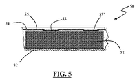
この構成の断面50が図5に概略的に表されており、圧縮されたゲッタ材料51からなるピルが平坦なホルダ底部52上に配置され、穴あきカバー55の一部である網54のくぼみ53、53’によって垂直方向において抑止される。
A
そのような構成は、垂直方向への変位に関してピルを抑止するという利点も有する。 Such a configuration also has the advantage of deterring pills with respect to vertical displacement.
更に好ましい実施形態は、全方向においてピルの変位を抑止するために、くぼみのある穴あきカバー及び弾性要素の両方の使用を想定するが、それらを単独で採用することもできる。 Further preferred embodiments envisage the use of both a recessed perforated cover and an elastic element to suppress pill displacement in all directions, but they can also be employed alone.
上記のように、本発明によれば、結果としてピル構造を分解し、それゆえ、粉末を生成することにつながる現象が最小限に抑えられる。それにもかかわらず、そのような現象は常に存在し、水素収着後にピルが脆弱になる結果として、時間の経過とともに徐々に悪化する性質を有するので、粉末を効果的に閉じ込めるために、特に目の詰んだ編み方のメッシュ又は網を有するホルダを提供することが好ましい。 As mentioned above, according to the present invention, the phenomena that result in the decomposition of the pill structure and hence the production of powder are minimized. Nevertheless, such a phenomenon always exists and has the property of gradually worsening over time as a result of the pill becoming fragile after hydrogen sorption, so it is particularly important to confine the powder effectively. It is preferred to provide a holder having a knitted mesh or net.
10 ゲッタシステム
11 ゲッタ材料ピル
11’ ゲッタ材料ピル
11” ゲッタ材料ピル
12 底部
13 側方肩部
13’ 側方肩部
14 金網
15 要素
15’ 係止要素
20 ゲッタシステム
21 ゲッタ材料ピル
21’ ゲッタ材料ピル
21” ゲッタ材料ピル
22 金属メッシュ
23 カバー
24 タブ
31 弾性要素
32 弾性要素
33 弾性要素
34 弾性要素
311 部分
312 部分
321 部分
322 部分
331 部分
332 部分
341 部分
342 部分
40 ホルダ
41 弾性要素
42 ゲッタ材料ピル
42’ ゲッタ材料ピル
50 断面
51 ゲッタ材料
52 ホルダ底部
53 くぼみ
53’ くぼみ
54 網
55 穴あきカバー
DESCRIPTION OF
【書類名】明細書
【発明の名称】太陽熱集熱器集熱管に対する改善
【技術分野】
【0001】
本発明は太陽熱集熱器集熱管に対する改善に関連する。
【背景技術】
【0002】
太陽熱集熱器は、益々重要な代替のエネルギー源になりつつある。これらのデバイス、より具体的には、太陽熱集熱器の集熱管では、水素の存在は、熱除去流体が流れる中央管状体から集熱管の外側に向かって熱伝導を高め、それゆえ、その効率を徐々に低下させるので、水素の存在は有害である。中央管状体内を流れる流体は、高温において分解し、水素を生成する傾向があるので、この場合、水素の存在に関する問題が特に関連する問題となる。
【0003】
更に高い温度において熱を除去するために異なる流体タイプを利用する新世代の集熱管においても、そのような更に高い温度では集熱管の金属部分から更に多くの水素ガスが放出されるので、水素の存在に関連する問題、及び結果として生じるデバイス特性の劣化が特に問題となる。
【0004】
集熱管内には、ゲッタ材料を水素容量に関して好ましくない作動条件にする高い内部温度に関連する更なる問題もあり、水素容量は動作温度に反比例する。
【0005】
このために、特許文献1において開示されるような幾つかの技術的手段が開発されており、特許文献1は、集熱管内にゲッタ材料を配置し、効率的に収容するために、そりの形をとる構成を記述しており、その目的は、ゲッタ材料を太陽放射及び最も高い温度に達する集熱器の部分から遮蔽することである。
【0006】
このタイプの構成では、通常、標準的な、すなわち、直径10mmの、圧縮粉末からなるピルの形のゲッタ材料が利用されるために幾つかの欠点があり、これは、集熱管内に十分な量のゲッタ材料を導入して、20〜30年にわたって適切なデバイス動作を確保できるようにするために、全てのそりが2つのピルラインを収容することを暗示しており、通常、各集熱管には2つのそりが収容される。
【0007】
これは異なる性質の2つの問題を引き起こし、一方では、互いに隣接する2つのゲッタピルラインの形でゲッタ材料を装填する際に、より大きな困難があるという問題であり、他方では、互いに接触し、かつそり壁と接触するピルの接触箇所の数が増えるという問題である。
【0008】
これらの接触箇所は選択的に脆弱性である領域を生み出し、結果として粉末が生成される。粉末の生成、及びその後のピルからの脱離は、それらの粉末が適切な閉じ込め金属メッシュによって閉じ込められる場合でも、できる限り少なくすべき現象である。これらの脱離した粉末は、美感の面だけでなく、機能の面からも問題を引き起こす(例えば、放射に暴露される表面の透明性が劣化し、結果として集熱管の熱効率が低下する)。
【先行技術文献】
【特許文献】
【0009】
【特許文献1】米国特許第6832608号
【特許文献2】米国特許第3203901号
【特許文献3】米国特許第4306887号
【特許文献4】英国特許第2077487号
【特許文献5】米国特許第5961750号
【特許文献6】国際公開第2007/148362号
【特許文献7】国際公開第2007/099575号
【特許文献8】国際公開第2010/105945号
【特許文献9】 米国特許第3225910号
【特許文献10】 米国特許出願公開第2008/0272333号
【特許文献11】 米国特許出願公開第2004/0056343号
【発明の概要】
【発明が解決しようとする課題】
【課題を解決するための手段】
【0010】
本発明の目的は、この現象の激しさを緩和することであり、その第1の態様では、本発明は、機械的支持体及びゲッタ材料の圧縮粉末のピルを備えるゲッタシステムを含む太陽熱集熱器集熱管にあり、その機械的支持体は底部及び2つの側方肩部からなるホルダを含み、ゲッタ粉末ピルは15mm以上の直径を有し、直径/高さ比は2〜5からなり、それらのピルは単一のラインでホルダ底部においてホルダ内に収容されることを特徴とする。
【0011】
特許文献9は、単一のライン内に配置されるゲッタピルの一例を開示するが、その特許は、ピルのための如何なる寸法範囲も提供せず、それらのピルは互いに接触しない場合もあり、電子管内の真空を保持するために用いられる。
【0012】
ゲッタシステムの先に参照されたホルダはU字形そりと言うこともでき、本発明の目的において、2つの用語は同等の意味を有する。
【0013】
本発明は、以下の図面の助けを借りて以下に説明される。
【図面の簡単な説明】
【0014】
【図1A】本発明による、集熱管内で使用されることになるゲッタシステムの第1の実施形態の側面図である。
【図1B】本発明による、集熱管内で使用されることになるゲッタシステムの第1の実施形態の平面図である。
【図2A】本発明による、集熱管内で使用されることになるゲッタシステムの代替の実施形態の側面図である。
【図2B】本発明による、集熱管内で使用されることになるゲッタシステムの代替の実施形態の平面図である。
【図3】機械的支持体内で使用されることになる弾性要素のための幾つかの可能な実施形態を示す図である。
【図4】図3に示される弾性要素のうちの1つを組み込む、集熱管内で使用されることになるゲッタシステムの平面図である。
【図5】集熱管内で使用されることになるゲッタシステムの別の実施形態の断面図である。
【発明を実施するための形態】
【0015】
図面では、要素の寸法及び寸法比は、それには限らないが、金属メッシュ開口部の寸法を参照する場合に特に、正確ではなく、本発明の図解を理解しやすくするために変更されている。さらに、例えば、オプションの遮熱材、又はホルダ/そりのための固定手段のような、オプションで存在する幾つかの要素は、本発明を理解する上で不可欠ではないので、図示されていない。
【0016】
本発明によれば、ゲッタ材料ピルをそのハウジングホルダに装填する動作が著しく簡略化される。
【0017】
ゲッタ材料ピルの表面積を増やすと、表面積が小さいピルに比べて特性が劣化することは理解されたい。それにもかかわらず、この劣化は、その技術分野、すなわち、太陽熱集熱器集熱管に具体的に関連付けられる上記の利点によって補償される。
【0018】
実際には、同じ高さのままピルの表面が増加すると、脆弱になり、結果として取り扱うのが難しくなるが、一方、高さが増す結果として、排気速度に悪影響を及ぼすことになり、ピル内部領域に達する際にガス状の不純物に遭遇するという問題がある。それゆえ、直径を大きくしたピルを採用する際に予想される悪影響に起因して、当業者がそのような解決策を採用するには至っていなかった。また、本発明において使用されることになるゲッタピルは、ゲッタ材料の粉末を適切に圧縮することによって得られるので、結合剤を含まないことも強調されるべきであり、結合剤が含まれていれば、各ピルによって吸着される水素の量を意味する、材料の容量に影響を及ぼしていた。これは、太陽熱集熱器の応用形態においてうまく利用するためのピル構造抵抗及び関連する制約に影響を及ぼす根本的な態様である。
【0019】
上記の逆の現象を考慮して、ピル直径とその高さとの最適な比は2〜5からなり、全く同じ理由から、35mmよりも大きな直径を有するピルの場合に問題が現れ始める。
【0020】
特許文献10は、はるかに広い範囲の直径/高さ比を有するゲッタピルを開示しており、その比は0.4から60まで様々であり、直径は2mm程度と小さく、本出願における最小ピル高が3mmであるのに対して高さは0.5mm程度と低く、これらのピルは、その強度を高めるために結合剤を含む場合がある。
【0021】
特許文献11は、約20mmの直径及び約2.5の直径/高さ比を有するゲッタピルの単一の例を開示するが、しかしながら、そのピルは、製造するために、重量比で5%〜25%の無機結合剤を必要とする。
【0022】
そのようなピルは、太陽熱集熱器の要件を満たすのに適しておらず、結合剤の存在が、その水素収着容量に悪影響を及ぼす。
【0023】
ピル直径は18mm〜25mmから構成され、その直径と高さとの比は3〜4から構成されることが好ましい。そのような寸法特性を有するピルを装填されたホルダとともに動作させることによって、1つのホルダ/そりのみを用いることによって、20〜30年のデバイス寿命を保証することができる十分な量のゲッタ材料を集熱管内に挿入することができる。これに反して、現在利用されている構成は、集熱管毎に2つの異なるホルダを使用することを想定しており、ホルダだけでなく、機械的支持体を完成させる要素、すなわち、閉じ込め金属メッシュ、スペーサ及び適切な遮熱材を含む構造的なコストに加えて、位置決め及び固定に関連する問題を伴う。
【0024】
また、ホルダはピル直径よりも1mm〜3mm広い幅を有することが好ましく、これは、ホルダ内でピルが或る程度適応できるようにすることによって、ゲッタ材料による水素収着の結果としてピル構造が膨張することに関連する技術的問題を解決する。
【0025】
側方肩部を構成する要素の高さを意味する、ホルダの高さに関して、図1Bの要素14のような、ホルダのための上部閉鎖システムとして金網を使用することを想定する更に好ましい実施形態では、側方肩部の高さは、ピル高よりも0.5mm〜1mm低い。これは、網自体がゲッタ材料ピルのための抑止要素としての役割も果たし、その往復運動、及び衝突の結果としてピルが砕けて、それにより粉末の生成が増加する可能性を制限するのを保証する。
【0026】
図2Aに示される要素23の場合と同様に、上部閉鎖システムの一部が硬質である場合、全く同じ理由、及び上記の技術的効果から、肩部高は、ピル高よりも1mm〜3mm高いことが好ましい。
【0027】
更に好ましい実施形態では、ホルダは、1つ又は複数のゲッタ材料ピルと直接接触する1つ又は複数の弾性要素も含む。
【0028】
これらの弾性要素の主な機能は、ピルに適切な圧縮力を加えて、ピルが互いに押し合うようにすることである。この作用は、ゲッタピルが、ゲッタピルの寸法よりも大きいホルダ、その最も有用な表現では、そり内に収容される場合であっても、弾性要素によって及ぼされる圧縮が、ホルダ内でピルが動くのを防ぐ。
【0029】
圧力値が過剰であると、ホルダ内でピルが動くのを抑止することによって破壊を防ぐのではなく、ピル構造を破壊することになってしまうので、加えられる圧力値は重要なパラメータであり、厳密には応用分野に依存し、具体的に関連付けられる。そのような値の決定は、ゲッタ材料による水素収着の結果としてピルが膨張すること、及び水素収着の結果としてピル構造の脆弱性が増すことを考慮に入れるという事実によって更に困難になる。本発明人は、弾性手段によって加えられる圧縮力が50N〜150Nからなるべきであることがわかった。この値は、新たに導入されたゲッタシステムにおいて、それゆえ、ゲッタ材料ピルを「新品」と見なすことができる、すなわち、最小量の水素しか吸着していないときに検討及び測定された。
【0030】
さらに、選択的な粉末生成スポットを有するのを避けるために、弾性要素はゲッタ材料ピルとの接触領域において角張った角部をなくすべきであり、それにより、それらの弾性要素は、そのような接触箇所において、平坦な、又は丸みを帯びた表面を与えるべきである。そのような特徴は、これ以降「分散接触」と呼ばれる。
【0031】
ゲッタ材料に関しては、高温において使用される場合であっても、良好な水素収着容量を示す材料が好ましい。
【0032】
それゆえ、本発明にとって有用な好ましいゲッタ材料は、特許文献2(Zr−Al合金)、特許文献3(Zr−Fe合金)、特許文献4(Zr−V−Fe合金)、特許文献5(Zr−Co−希土類合金)において記述される材料である。例えば、特許文献6、第2007/099575号及び第2010/105945号において記述されるように、特に高温における水素収着に関しては、イットリウム合金の使用も知られている。上記のゲッタ合金は、本発明とともに使用されるのが好ましい材料であるが、開示される発明の概念とともに、任意の水素ゲッタ材料を利用することができる。さらに、複数の異なるゲッタ材料を用いて形成されるピルを使用することを想定することもできるか、又はホルダに異なるタイプのピルを装填することもできる。
【0033】
図1A及び図1Bでは、太陽熱集熱器集熱管のためのゲッタシステム10のための第1の実施形態が示されており、ゲッタ材料のピル11、11’、11”...がホルダの平坦な底部12上に整列しており、閉じ込め金網14が存在し、例えば、電気溶接によってホルダに固定される。
【0034】
図1に示される構成では、オプションの要素15も存在し、要素15はストッパとしての役割を果たし、ピルがホルダに装填されると機械的に動作する。図1Aは、ホルダ端部のうちの一方の近くにそのような要素15のうちの1つのみを示すが、図1Bに示されるように、第2の端部にも第2の係止要素15’が存在することができる。
【0035】
金網は種々の方法でホルダに固定することができ、例えば、ホルダ側方肩部13、13’上に固定することができるか、又はホルダの外面上に巻き付けて、平坦な底部12において固定することができる。この第2の事例において、好ましい固定構成によれば、網14の縁部をわずかに重ね合わせて、その後、網14をホルダに固定するために一度の電気溶接を実行する。
【0036】
図1A及び図1Bに示されるように、ホルダを集熱管内に固定するために必要とされる実現可能な手段と干渉するのを避けるために、金網は、ホルダの全長を覆わないように配置され、それにより、端部が開けておくことができる。
【0037】
図2A及び図2Bには、代替の実施形態が示されており、ゲッタシステム20は、ホルダ構造の底部に配置されるゲッタ材料ピル21、21’、21”...を含み、その構造は、開口部を含むカバー23によって閉じられ、開口部には金属メッシュ22が配置される。
【0038】
その後、カバー23は、図示されないが、例えば、クリューのような適切な固定手段によってホルダ底部に固定される。
【0039】
図2Aには、ホルダ底部上に配置されたゲッタ材料ピル21、21’、21”...のためのストッパとしての役割を果たすように折り込まれた幾つかのタブ24も存在する。
【0040】
この構成は、その上に金属メッシュを固定された半完成品のホルダカバーによって閉じたホルダ構造を製造できるようになり、それゆえ、本発明において使用されるゲッタシステムの組立作業を簡単にするという利点を有する。
【0041】
また、第2の実施形態において、好ましい実現形態では、ホルダの幅はピル直径に対してわずかに広く、その側方肩部高はピル高に対してわずかに低い。また、この場合、好ましい寸法は、ピル直径よりも1mm〜3mm広い幅と、ピル高よりも0.5mm〜1mm低い側方肩部高とを有するホルダを使用することを想定する。この実施形態では、ピルストッパ24もピルライン上にわずかな長手方向圧力を加え、それにより、ピルが横方向に動くのを制限するという目的にも役に立つ。
【0042】
これまでに説明された、図1A、図1B、図2A及び図2Bにおいて表される金網のような、本発明によるシステムにおいて用いられる金網の特性に関する限り、その網は、10μm〜500μmのサイズを有する穴、より一般的には隙間を有する。金網開口部は、20μm〜50μmから構成されることが好ましい。開口部が円形又は概ね円形でない場合、上記のサイズはその最大幅を指している。
【0043】
ホルダ内で使用されることになる弾性要素のための実現可能な実施形態の例が図3に示される。図示される各要素31、32、33及び34は、ゲッタピルと接触することになる部分311、312、321、322、331、332、341、342を有し、それらの部分は平坦であるか、又は丸みを帯びており、ゲッタピル表面との分散接触を実現するのに適している。
【0044】
図4は、そのような弾性要素のうちの1つの弾性要素41を含むホルダ40の平面図を示す。図4では、ホルダ上に配置されるゲッタ材料ピル42、42’...とともに、ホルダの1つのカバー要素のみが表されている。本発明のゲッタシステムのホルダを参照しながら、一般的に言うと、ホルダのカバー及び底部は、集熱管内でそれぞれ、外側に向けられているか(カバー)、又は管の内側部分に向けられている(底部)、ゲッタシステムの部品を特定する。それゆえ、カバー及び底部は幾何学的配置を指しており、ゲッタシステムが組み立てられる方法を指すものではなく、例えば、図4に示される実施形態では、ゲッタピルは、カバーになるはずの部品上に配置される。
【0045】
ゲッタシステムの代替の実施形態は、変更された穴あきカバーの使用を想定しており、そのカバーは、平坦な表面を与える代わりに、網内にゲッタピルと一致する一連の1つ又は複数のくぼみを与え、カバーとゲッタピルとの間の分散接触界面を達成するために、そのようなくぼみも丸みを帯びているか、又は平坦な接触面を与える。
【0046】
この構成の断面50が図5に概略的に表されており、圧縮されたゲッタ材料51からなるピルが平坦なホルダ底部52上に配置され、穴あきカバー55の一部である網54のくぼみ53、53’によって垂直方向において抑止される。
【0047】
そのような構成は、垂直方向への変位に関してピルを抑止するという利点も有する。
【0048】
更に好ましい実施形態は、全方向においてピルの変位を抑止するために、くぼみのある穴あきカバー及び弾性要素の両方の使用を想定するが、それらを単独で採用することもできる。
【0049】
上記のように、本発明によれば、結果としてピル構造を分解し、それゆえ、粉末を生成することにつながる現象が最小限に抑えられる。それにもかかわらず、そのような現象は常に存在し、水素収着後にピルが脆弱になる結果として、時間の経過とともに徐々に悪化する性質を有するので、粉末を効果的に閉じ込めるために、特に目の詰んだ編み方のメッシュ又は網を有するホルダを提供することが好ましい。
【符号の説明】
【0050】
10 ゲッタシステム
11 ゲッタ材料ピル
11’ ゲッタ材料ピル
11” ゲッタ材料ピル
12 底部
13 側方肩部
13’ 側方肩部
14 金網
15 要素
15’ 係止要素
20 ゲッタシステム
21 ゲッタ材料ピル
21’ ゲッタ材料ピル
21” ゲッタ材料ピル
22 金属メッシュ
23 カバー
24 タブ
31 弾性要素
32 弾性要素
33 弾性要素
34 弾性要素
311 部分
312 部分
321 部分
322 部分
331 部分
332 部分
341 部分
342 部分
40 ホルダ
41 弾性要素
42 ゲッタ材料ピル
42’ ゲッタ材料ピル
50 断面
51 ゲッタ材料
52 ホルダ底部
53 くぼみ
53’ くぼみ
54 網
55 穴あきカバー
[Document name] Description [Title of invention] Improvement of solar collector tube [Technical field]
[0001]
The present invention relates to improvements to solar collector tubes.
[Background]
[0002]
Solar collectors are becoming an increasingly important alternative energy source. In these devices, and more specifically in the solar collector tubes, the presence of hydrogen increases heat conduction from the central tubular body through which the heat removal fluid flows to the outside of the collector tube, and therefore its efficiency. The presence of hydrogen is harmful. Since the fluid flowing through the central tubular body tends to decompose at high temperatures and produce hydrogen, the problem with the presence of hydrogen is a particularly relevant problem in this case.
[0003]
Even in the new generation of collectors that utilize different fluid types to remove heat at higher temperatures, more hydrogen gas is released from the metal portion of the collector at such higher temperatures, so Problems related to existence and the resulting degradation of device characteristics are particularly problematic.
[0004]
There are additional problems associated with high internal temperatures in the heat collection tube that make the getter material unfavorable operating conditions with respect to hydrogen capacity, which is inversely proportional to the operating temperature.
[0005]
For this reason, several technical means as disclosed in Patent Document 1 have been developed. In Patent Document 1, a getter material is arranged in a heat collecting tube, and in order to efficiently accommodate the getter material, Describes a configuration that takes shape, the purpose of which is to shield the getter material from solar radiation and the part of the collector that reaches the highest temperature.
[0006]
This type of configuration usually has some disadvantages because a standard, i.e., 10 mm diameter, pill-shaped getter material consisting of compressed powder is utilized, which is sufficient in the heat collection tube. In order to introduce a quantity of getter material to ensure proper device operation over 20-30 years, all sleds imply that it will contain two pill lines, usually in each collector tube Accommodates two sleds.
[0007]
This causes two problems of different nature, on the one hand, the problem of greater difficulty in loading getter material in the form of two getter pill lines adjacent to each other, on the other hand, contacting each other, The problem is that the number of contact points of the pill that comes into contact with the sledge wall increases.
[0008]
These contact points selectively create areas that are fragile, resulting in a powder. The generation of powder and subsequent desorption from the pill is a phenomenon that should be minimized as much as possible even when the powder is confined by a suitable confined metal mesh. These detached powders cause problems not only in terms of aesthetics but also in terms of function (for example, the transparency of the surface exposed to radiation is degraded, resulting in a decrease in the thermal efficiency of the heat collection tube).
[Prior art documents]
[Patent Literature]
[0009]
[Patent Document 1] US Pat. No. 6,832,608 [Patent Document 2] US Pat. No. 3,320,901 [Patent Document 3] US Pat. No. 4,306,887 [Patent Document 4] British Patent No. 2077487 [Patent Document 5] US Pat. No. 5,961,750 [Patent Document 6] International Publication No. 2007/148362 [Patent Document 7] International Publication No. 2007/099575 [Patent Document 8] International Publication No. 2010/105945
[Patent Document 9] US Pat. No. 3,225,910
[Patent Document 10] US Patent Application Publication No. 2008/0272333
[Patent Document 11] US Patent Application Publication No. 2004/0056343 Summary of the Invention
[Problems to be solved by the invention]
[Means for Solving the Problems]
[0010]
The object of the present invention is to mitigate the severity of this phenomenon, and in its first aspect, the present invention comprises a solar heat collecting system comprising a getter system comprising a mechanical support and a pill of compressed powder of getter material. In the collector tube, the mechanical support comprises a holder consisting of a bottom and two lateral shoulders, the getter powder pill has a diameter of 15 mm or more, the diameter / height ratio consists of 2-5, The pills are characterized in that they are received in the holder at the bottom of the holder in a single line.
[0011]
Patent document 9 discloses an example of getter pills arranged in a single line, but that patent does not provide any size range for the pills, which may not contact each other, Used to maintain the vacuum in the tube.
[0012]
The previously referenced holder of the getter system can also be referred to as a U-shaped sled, and for the purposes of the present invention, the two terms have equivalent meanings.
[0013]
The invention is described below with the help of the following drawings.
[Brief description of the drawings]
[0014]
FIG. 1A is a side view of a first embodiment of a getter system to be used in a heat collection tube according to the present invention.
FIG. 1B is a plan view of a first embodiment of a getter system to be used in a heat collection tube according to the present invention.
FIG. 2A is a side view of an alternate embodiment of a getter system to be used in a heat collection tube according to the present invention.
2B is a plan view of an alternative embodiment of a getter system to be used in a heat collection tube according to the present invention. FIG.
FIG. 3 shows some possible embodiments for an elastic element to be used in a mechanical support.
4 is a plan view of a getter system to be used in a heat collecting tube that incorporates one of the elastic elements shown in FIG.
FIG. 5 is a cross-sectional view of another embodiment of a getter system to be used in a heat collection tube.
BEST MODE FOR CARRYING OUT THE INVENTION
[0015]
In the drawings, the dimensions and ratios of the elements are not limited, but are particularly accurate when referring to the dimensions of the metal mesh openings, and have been changed to make the illustration of the invention easier to understand. In addition, some optional elements such as, for example, an optional heat shield, or a securing means for the holder / sledge are not shown because they are not essential to understanding the present invention.
[0016]
According to the present invention, the operation of loading the getter material pill into its housing holder is greatly simplified.
[0017]
It should be understood that increasing the surface area of the getter material pill degrades the properties compared to a pill with a small surface area. Nevertheless, this degradation is compensated by the above-mentioned advantages that are specifically associated with the technical field, namely solar collector tubes.
[0018]
In fact, if the pill surface increases at the same height, it becomes fragile and difficult to handle as a result, while increasing the height will adversely affect the pumping speed and cause an increase in pill internals. There is a problem of encountering gaseous impurities when reaching the region. Therefore, those skilled in the art have not adopted such a solution due to the adverse effects expected when adopting a pill with an increased diameter. It should also be emphasized that the getter pills to be used in the present invention are obtained by appropriately compressing the powder of the getter material, so that they do not contain a binder. For example, it affected the capacity of the material, meaning the amount of hydrogen adsorbed by each pill. This is a fundamental aspect that affects pill structure resistance and related constraints for successful use in solar collector applications.
[0019]
Considering the reverse phenomenon described above, the optimum ratio of pill diameter to its height is 2-5, and for exactly the same reason, problems begin to appear for pills with diameters greater than 35 mm.
[0020]
[0021]
U.S. Patent No. 6,057,031 discloses a single example of a getter pill having a diameter of about 20 mm and a diameter / height ratio of about 2.5, however, the pill is 5% by weight to manufacture, Requires 25% inorganic binder.
[0022]
Such pills are not suitable to meet the requirements of solar collectors, and the presence of the binder adversely affects its hydrogen sorption capacity .
[0023]
The pill diameter is preferably 18 mm to 25 mm, and the ratio of the diameter to the height is preferably 3 to 4. By operating with a pill loaded holder with such dimensional characteristics, by using only one holder / sled, a sufficient amount of getter material that can guarantee a device life of 20-30 years It can be inserted into the heat collecting tube. On the other hand, the currently utilized configuration assumes the use of two different holders for each heat collection tube, and not only the holder but also the element that completes the mechanical support, ie the confined metal mesh In addition to the structural costs of including spacers and appropriate heat shields, there are problems associated with positioning and securing.
[0024]
Also, the holder preferably has a width that is 1 to 3 mm wider than the pill diameter, which allows the pill to adapt to some extent within the holder, resulting in a pill structure as a result of hydrogen sorption by the getter material. Solve the technical problems associated with swelling.
[0025]
Further preferred embodiments that envisage the use of a wire mesh as the upper closure system for the holder, such as
[0026]
As in the case of
[0027]
In a further preferred embodiment, the holder also includes one or more elastic elements that are in direct contact with the one or more getter material pills.
[0028]
The main function of these elastic elements is to apply an appropriate compressive force to the pills so that the pills press against each other. This effect is due to the compression exerted by the elastic element causing the pill to move within the holder, even when the getter pill is larger than the size of the getter pill, its most useful representation being contained within the sled. prevent.
[0029]
If the pressure value is excessive, the pill structure will be destroyed instead of preventing the pill from moving in the holder, so the applied pressure value is an important parameter. Strictly speaking, it depends on the application field and is specifically related. The determination of such values is further made difficult by the fact that it takes into account the expansion of the pill as a result of hydrogen sorption by the getter material and the increased pill structure vulnerability as a result of hydrogen sorption. The inventor has found that the compressive force applied by the elastic means should be between 50N and 150N. This value was examined and measured in a newly introduced getter system and therefore when the getter material pill can be considered "new", i.e., it has adsorbed only a minimal amount of hydrogen.
[0030]
Furthermore, in order to avoid having selective powder production spots, the elastic elements should be free of angular corners in the contact area with the getter material pill, so that these elastic elements are not in contact with such In place, it should give a flat or rounded surface. Such a feature is hereinafter referred to as “dispersed contact”.
[0031]
As for the getter material, a material showing a good hydrogen sorption capacity is preferable even when used at a high temperature.
[0032]
Therefore, preferred getter materials useful for the present invention include Patent Document 2 (Zr—Al alloy), Patent Document 3 (Zr—Fe alloy), Patent Document 4 (Zr—V—Fe alloy), and Patent Document 5 (Zr). -Co-rare earth alloys). For example, the use of yttrium alloys is also known, particularly for hydrogen sorption at high temperatures, as described in US Pat. Nos. 6,099,575 and 2010/105945. While the above getter alloys are preferred materials for use with the present invention, any hydrogen getter material can be utilized with the disclosed inventive concepts. Furthermore, it can be envisaged to use pills formed with several different getter materials, or the holder can be loaded with different types of pills.
[0033]
1A and 1B show a first embodiment for a
[0034]
In the configuration shown in FIG. 1, there is also an
[0035]
The wire mesh can be fixed to the holder in various ways, for example it can be fixed on the
[0036]
As shown in FIGS. 1A and 1B, the wire mesh is arranged not to cover the entire length of the holder in order to avoid interfering with the feasible means needed to secure the holder in the heat collecting tube. So that the end can be left open.
[0037]
2A and 2B show an alternative embodiment, where the
[0038]
Thereafter, although not shown, the
[0039]
In FIG. 2A there are also
[0040]
This configuration allows for the production of a closed holder structure with a semi-finished holder cover on which a metal mesh is secured, thus simplifying the assembly of the getter system used in the present invention. Have advantages.
[0041]
Also in the second embodiment, in a preferred implementation, the width of the holder is slightly wider relative to the pill diameter and its side shoulder height is slightly lower than the pill height. Also, in this case, it is assumed that a preferable dimension is to use a holder having a width that is 1 mm to 3 mm wider than the pill diameter and a side shoulder height that is 0.5 mm to 1 mm lower than the pill height. In this embodiment, the
[0042]
As far as the properties of the wire mesh used in the system according to the invention, such as the wire mesh represented in FIGS. Holes, more generally gaps. The wire mesh opening is preferably composed of 20 μm to 50 μm. If the opening is not circular or generally circular, the above size refers to its maximum width.
[0043]
An example of a possible embodiment for an elastic element to be used in a holder is shown in FIG. Each
[0044]
FIG. 4 shows a plan view of a
[0045]
An alternative embodiment of the getter system envisions the use of a modified perforated cover, which instead of providing a flat surface, a series of one or more indentations that coincide with the getter pills in the net. In order to achieve a distributed contact interface between the cover and the getter pill, such depressions are also rounded or provide a flat contact surface.
[0046]
A
[0047]
Such a configuration also has the advantage of deterring pills with respect to vertical displacement.
[0048]
Further preferred embodiments envisage the use of both a recessed perforated cover and an elastic element to suppress pill displacement in all directions, but they can also be employed alone.
[0049]
As mentioned above, according to the present invention, the phenomena that result in the decomposition of the pill structure and hence the production of powder are minimized. Nevertheless, such a phenomenon always exists and has the property of gradually worsening over time as a result of the pill becoming fragile after hydrogen sorption, so it is particularly important to confine the powder effectively. It is preferred to provide a holder having a knitted mesh or net.
[Explanation of symbols]
[0050]
DESCRIPTION OF
Claims (17)
Applications Claiming Priority (3)
| Application Number | Priority Date | Filing Date | Title |
|---|---|---|---|
| ITMI2010A001519 | 2010-08-06 | ||
| IT001519A ITMI20101519A1 (en) | 2010-08-06 | 2010-08-06 | IMPROVEMENTS FOR TUBES RECEIVERS OF SOLAR COLLECTORS |
| PCT/EP2011/062678 WO2012016865A1 (en) | 2010-08-06 | 2011-07-22 | Improvements for solar collectors receiver tubes |
Publications (2)
| Publication Number | Publication Date |
|---|---|
| JP2013534303A true JP2013534303A (en) | 2013-09-02 |
| JP2013534303A5 JP2013534303A5 (en) | 2014-08-07 |
Family
ID=43739516
Family Applications (1)
| Application Number | Title | Priority Date | Filing Date |
|---|---|---|---|
| JP2013522193A Pending JP2013534303A (en) | 2010-08-06 | 2011-07-22 | Improvements to solar collector collector tubes. |
Country Status (6)
| Country | Link |
|---|---|
| US (1) | US20130125874A1 (en) |
| EP (1) | EP2601453A1 (en) |
| JP (1) | JP2013534303A (en) |
| CN (1) | CN103080666A (en) |
| IT (1) | ITMI20101519A1 (en) |
| WO (1) | WO2012016865A1 (en) |
Cited By (1)
| Publication number | Priority date | Publication date | Assignee | Title |
|---|---|---|---|---|
| JP2015509180A (en) * | 2012-02-03 | 2015-03-26 | サエス・ゲッターズ・エッセ・ピ・ア | Improvement of solar energy collector receiving tube |
Families Citing this family (2)
| Publication number | Priority date | Publication date | Assignee | Title |
|---|---|---|---|---|
| ITMI20111492A1 (en) * | 2011-08-04 | 2013-02-05 | Getters Spa | IMPROVEMENTS FOR RECEIVER TUBES FOR SOLAR COLLECTORS |
| ES2454775B1 (en) * | 2012-10-11 | 2015-03-10 | Abengoa Solar New Tech Sa | Vacuum tuning system in heat transfer tube |
Citations (6)
| Publication number | Priority date | Publication date | Assignee | Title |
|---|---|---|---|---|
| US2167852A (en) * | 1935-10-22 | 1939-08-01 | Rca Corp | Electron discharge device |
| US3225910A (en) * | 1961-02-04 | 1965-12-28 | Porta Paolo Della | Getter devices with non-evaporated gettering material, for maintaining vacuum in electronic tubes |
| WO2002043098A1 (en) * | 2000-11-22 | 2002-05-30 | Johnson Matthey Plc | Getters |
| JP2002212605A (en) * | 2001-01-18 | 2002-07-31 | Sumitomo Kinzoku Technol Kk | Nonsintered molded getter |
| US20040134484A1 (en) * | 2003-01-09 | 2004-07-15 | Menashe Barkai | Getter support assembly for a solar energy collector system |
| US20080272333A1 (en) * | 2004-12-17 | 2008-11-06 | Patricia Blanco-Garcia | Hydrogen Getter |
Family Cites Families (7)
| Publication number | Priority date | Publication date | Assignee | Title |
|---|---|---|---|---|
| US3203901A (en) | 1962-02-15 | 1965-08-31 | Porta Paolo Della | Method of manufacturing zirconiumaluminum alloy getters |
| IT1115156B (en) | 1979-04-06 | 1986-02-03 | Getters Spa | ZR-FE ALLOYS FOR HYDROGEN ABSORPTION AT LOW TEMPERATURES |
| IT1198325B (en) | 1980-06-04 | 1988-12-21 | Getters Spa | STRUCTURE AND COMPOSITION GETTERANTS, PARTICULARLY SUITABLE FOR LOW TEMPERATURES |
| IT1290451B1 (en) | 1997-04-03 | 1998-12-03 | Getters Spa | NON-EVAPORABLE GETTER ALLOYS |
| ITMI20060361A1 (en) | 2006-02-28 | 2007-09-01 | Getters Spa | HYDROGEN ABSORPTION THROUGH THE USE OF NON EVAPORABLE GETTER ALLOYS METHOD AND APPLICATIONS |
| ITMI20061173A1 (en) | 2006-06-19 | 2007-12-20 | Getters Spa | NON EVAPORABLE GETTER ALLOYS PARTICULARLY SUITABLE FOR HYDROGEN ABSORPTION |
| ITMI20090410A1 (en) | 2009-03-18 | 2010-09-19 | Getters Spa | NON EVAPORABLE GETTER ALLOYS PARTICULARLY SUITABLE FOR HYDROGEN ABSORPTION |
-
2010
- 2010-08-06 IT IT001519A patent/ITMI20101519A1/en unknown
-
2011
- 2011-07-22 US US13/813,902 patent/US20130125874A1/en not_active Abandoned
- 2011-07-22 JP JP2013522193A patent/JP2013534303A/en active Pending
- 2011-07-22 EP EP11735440.7A patent/EP2601453A1/en not_active Withdrawn
- 2011-07-22 CN CN2011800387131A patent/CN103080666A/en active Pending
- 2011-07-22 WO PCT/EP2011/062678 patent/WO2012016865A1/en active Application Filing
Patent Citations (8)
| Publication number | Priority date | Publication date | Assignee | Title |
|---|---|---|---|---|
| US2167852A (en) * | 1935-10-22 | 1939-08-01 | Rca Corp | Electron discharge device |
| US3225910A (en) * | 1961-02-04 | 1965-12-28 | Porta Paolo Della | Getter devices with non-evaporated gettering material, for maintaining vacuum in electronic tubes |
| WO2002043098A1 (en) * | 2000-11-22 | 2002-05-30 | Johnson Matthey Plc | Getters |
| US20040056343A1 (en) * | 2000-11-22 | 2004-03-25 | Casci John Leonello | Getters |
| JP2004532093A (en) * | 2000-11-22 | 2004-10-21 | ジョンソン、マッセイ、パブリック、リミテッド、カンパニー | Getter |
| JP2002212605A (en) * | 2001-01-18 | 2002-07-31 | Sumitomo Kinzoku Technol Kk | Nonsintered molded getter |
| US20040134484A1 (en) * | 2003-01-09 | 2004-07-15 | Menashe Barkai | Getter support assembly for a solar energy collector system |
| US20080272333A1 (en) * | 2004-12-17 | 2008-11-06 | Patricia Blanco-Garcia | Hydrogen Getter |
Cited By (1)
| Publication number | Priority date | Publication date | Assignee | Title |
|---|---|---|---|---|
| JP2015509180A (en) * | 2012-02-03 | 2015-03-26 | サエス・ゲッターズ・エッセ・ピ・ア | Improvement of solar energy collector receiving tube |
Also Published As
| Publication number | Publication date |
|---|---|
| WO2012016865A1 (en) | 2012-02-09 |
| US20130125874A1 (en) | 2013-05-23 |
| CN103080666A (en) | 2013-05-01 |
| EP2601453A1 (en) | 2013-06-12 |
| ITMI20101519A1 (en) | 2012-02-07 |
Similar Documents
| Publication | Publication Date | Title |
|---|---|---|
| US9103565B2 (en) | Solar collectors receiver tubes | |
| US7721513B2 (en) | Construction for multi-layered vacuum super insulated cryogenic tank | |
| JP2013534303A (en) | Improvements to solar collector collector tubes. | |
| KR20040084683A (en) | Gas storage tank and its manufacturing method | |
| TW201128106A (en) | Hydrogen storage device | |
| JP2013511003A (en) | Hydrogen storage tank with metal hydride | |
| JP2015014444A (en) | Heat collection pipe | |
| US20130025585A1 (en) | Getter system for hydrogen sensitive devices | |
| JP5568785B2 (en) | Nuclear fuel rod | |
| JP5926404B2 (en) | Improvement of solar energy collector receiving tube | |
| JP2503472B2 (en) | Hydrogen storage metal container | |
| JP2939307B2 (en) | Reactor control rod | |
| CN110061279B (en) | Recombination device | |
| CN220366276U (en) | Metal hydride hydrogen storage tank | |
| JP2004316673A (en) | Gas storage tank and its manufacturing method | |
| JP2008151283A (en) | Gas storage vessel | |
| JP2013217762A (en) | Nuclear fuel element and fuel assembly | |
| RU2005118292A (en) | METHOD FOR SEALING A NUCLEAR REACTOR HEAT FUEL ELEMENT | |
| JPS58145601A (en) | Reaction vessel for metal hydride | |
| BE396114A (en) |
Legal Events
| Date | Code | Title | Description |
|---|---|---|---|
| A521 | Request for written amendment filed |
Free format text: JAPANESE INTERMEDIATE CODE: A523 Effective date: 20140618 |
|
| A621 | Written request for application examination |
Free format text: JAPANESE INTERMEDIATE CODE: A621 Effective date: 20140618 |
|
| A977 | Report on retrieval |
Free format text: JAPANESE INTERMEDIATE CODE: A971007 Effective date: 20150320 |
|
| A131 | Notification of reasons for refusal |
Free format text: JAPANESE INTERMEDIATE CODE: A131 Effective date: 20150413 |
|
| A02 | Decision of refusal |
Free format text: JAPANESE INTERMEDIATE CODE: A02 Effective date: 20150914 |