KR20140049499A - Heating device - Google Patents
Heating device Download PDFInfo
- Publication number
- KR20140049499A KR20140049499A KR1020137021580A KR20137021580A KR20140049499A KR 20140049499 A KR20140049499 A KR 20140049499A KR 1020137021580 A KR1020137021580 A KR 1020137021580A KR 20137021580 A KR20137021580 A KR 20137021580A KR 20140049499 A KR20140049499 A KR 20140049499A
- Authority
- KR
- South Korea
- Prior art keywords
- heating
- heating device
- heating surface
- sheet
- smaller
- Prior art date
Links
Images
Classifications
-
- B—PERFORMING OPERATIONS; TRANSPORTING
- B29—WORKING OF PLASTICS; WORKING OF SUBSTANCES IN A PLASTIC STATE IN GENERAL
- B29B—PREPARATION OR PRETREATMENT OF THE MATERIAL TO BE SHAPED; MAKING GRANULES OR PREFORMS; RECOVERY OF PLASTICS OR OTHER CONSTITUENTS OF WASTE MATERIAL CONTAINING PLASTICS
- B29B13/00—Conditioning or physical treatment of the material to be shaped
- B29B13/02—Conditioning or physical treatment of the material to be shaped by heating
- B29B13/023—Half-products, e.g. films, plates
-
- H—ELECTRICITY
- H05—ELECTRIC TECHNIQUES NOT OTHERWISE PROVIDED FOR
- H05B—ELECTRIC HEATING; ELECTRIC LIGHT SOURCES NOT OTHERWISE PROVIDED FOR; CIRCUIT ARRANGEMENTS FOR ELECTRIC LIGHT SOURCES, IN GENERAL
- H05B3/00—Ohmic-resistance heating
- H05B3/0095—Heating devices in the form of rollers
Landscapes
- Physics & Mathematics (AREA)
- Thermal Sciences (AREA)
- Engineering & Computer Science (AREA)
- Mechanical Engineering (AREA)
- Casting Or Compression Moulding Of Plastics Or The Like (AREA)
- Processing And Handling Of Plastics And Other Materials For Molding In General (AREA)
- Treatment Of Fiber Materials (AREA)
- Paper (AREA)
- General Induction Heating (AREA)
Abstract
본 발명은 시트(6)용 가열 장치(3)에 관한 것으로서, 적어도 제 1 가열면(1) 및 제 2 가열면(2)을 포함하고, 제 1 및 제 2 가열면(1, 2)은 제 1 및 제 2 가열면(1, 2)이 서로의 상부에 있도록 배열되고, 적어도 2개의 안내 요소(4)가 제 1 및 제 2 가열면(1, 2) 사이에 배열되어, 시트(6)가 제 1 및 제 2 가열면(1, 2) 사이로 안내되게 되고, 제 1 및/또는 제 2 가열면(1, 2)은 적어도 하나의 단부에서 정점 형태를 갖는다. 본 발명은 또한 가열 장치(3)를 포함하는 제조 장치에 관한 것이다.The present invention relates to a heating device (3) for a sheet (6), comprising at least a first heating surface (1) and a second heating surface (2), wherein the first and second heating surfaces (1, 2) The first and second heating surfaces 1, 2 are arranged on top of each other, and at least two guide elements 4 are arranged between the first and second heating surfaces 1, 2, so that the sheet 6 ) Is guided between the first and second heating surfaces 1, 2, and the first and / or second heating surfaces 1, 2 have a vertex shape at at least one end. The invention also relates to a manufacturing apparatus comprising a heating device 3.
Description
본 발명은 청구항 1의 전제부에 따른 시트용 가열 장치에 관한 것이다.The present invention relates to a heating device for sheets according to the preamble of claim 1.
가열 장치가 관련 분야에 공지되어 있다. 문헌 EP 0 131 879호에는 예를 들어 핫플레이트에 의한 라미네이트 제조를 위한 이중 벨트 프레스가 개시되어 있다. 핫플레이트는 재료를 가열하기 위해 2개의 쌍의 롤 사이에 배열된다. 문헌 US 5,063,010호에는 예열기를 사용하는 보드 제조 방법이 개시되어 있다. 문헌 US 5,063,010호의 도 2에는 예열 유닛이 정점형 플레이트를 포위하는 것이 개시되어 있다.Heating devices are known in the art. Document EP 0 131 879 discloses a double belt press for the production of laminates, for example by hot plates. The hotplate is arranged between two pairs of rolls to heat the material. Document US 5,063,010 discloses a method of making a board using a preheater. 2 of the document US 5,063,010 discloses that the preheating unit surrounds the vertex plate.
GB 621 783호는 프레스 공구에 의해 이들을 추가로 처리하기 전에 베이클라이트(Bakelite)와 같은 절연 재료를 가열하기 위한 가열 수단을 설명하고 있다. 장치는 평행 배열의 2개의 세장형 가열 요소 및 가이드로 이루어진다.GB 621 783 describes heating means for heating insulating materials such as Bakelite before further processing them by a press tool. The device consists of two elongate heating elements and a guide in a parallel arrangement.
US 2,356,998호는 재료를 펀칭하기 전에, 합성 수지 니스칠된 페이퍼와 같은 시트 재료를 가열하기 위한 방법 및 장치를 개시하고 있다. 가열 장치는 2개의 평행한 가열 요소 및 2개의 이격된 안내 가이드로 이루어진다.US 2,356,998 discloses a method and apparatus for heating sheet materials, such as synthetic resin varnished paper, before punching the material. The heating device consists of two parallel heating elements and two spaced guide guides.
US 6,297,478호는 한 쌍의 가열체 및 홈을 갖는 가이드로 이루어지는 가열 유닛을 개시하고 있다. 가열 유닛은 시프트 가능하다.US 6,297,478 discloses a heating unit consisting of a guide having a pair of heating bodies and grooves. The heating unit is shiftable.
전술된 문헌들의 장치는 재료의 부분을 가열하는 기능을 갖는다. 가열 장치는 추가의 기능을 제공하지 않는다. 불행하게도, 재료는 가열 장치 내부에서 슬립할 수 있고, 랜덤 변위로 가열 장치를 떠난다. 연속적인 장치는 이들 편차를 보상하기 위해 특정 방식으로 설계되어야 한다.The device of the aforementioned documents has the function of heating a part of the material. The heating device does not provide additional functionality. Unfortunately, the material can slip inside the heating device and leave the heating device at random displacement. Continuous devices must be designed in a specific way to compensate for these deviations.
따라서, 본 발명의 목적은 재료가 가열 장치 내부에서 슬립하는 것을 방지하는 가열 장치를 생성하는 것이다.Accordingly, it is an object of the present invention to create a heating device that prevents material from slipping inside the heating device.
청구항 1의 특징을 갖는 가열 장치가 상기 목적을 해결한다. 적어도 2개의 안내 요소의 사용으로 인해, 재료(예를 들어, 시트)가 가열면들 사이로 안내될 수 있다. 따라서, 시트는 가열 장치 내부에서 슬립하지 않고, 가열 장치의 고정부에서 가열 장치를 나온다. 인접한 장치 - 캘린더 롤과 같은 - 는 적응 없이 시트를 용이하게 수용할 수 있다. 가열 장치 내부의 시트의 슬립이 회피되기 때문에, 시트의 모든 부분은 가열 장치 내부에서 가열될 것이다. 시트의 부분이 가열 장치 외부로 슬립하는 것이 발생하지 않는다(이에 의해 이들 부분은 이어서 가열되지 않음).A heating device having the features of claim 1 solves the above object. Due to the use of at least two guide elements, a material (eg sheet) can be guided between the heating surfaces. Thus, the sheet does not slip inside the heating device, but exits the heating device at the stationary portion of the heating device. Adjacent devices-such as calendar rolls-can easily accommodate the sheet without adaptation. Since slip of the sheet inside the heating device is avoided, all parts of the sheet will be heated inside the heating device. It does not occur that parts of the sheet slip out of the heating device (thereby these parts are not subsequently heated).
이 사상의 개념에서, 용어인 시트는 그 폭이 두께보다 큰 테이프, 필름 및 다른 재료를 포함한다.In the concept of this idea, the term sheet includes tapes, films and other materials whose width is greater than the thickness.
제 1 및/또는 제 2 가열면은 가열면의 적어도 하나의 단부 상에 정점 형태를 갖는다. 정점 형태에 기인하여, 가열 장치는 다음의 장치에 매우 근접하여 배열될 수 있다. 이는 가열 장치와 후속의 장치 사이의 거리 - 이 거리에서 시트가 안내되지 않고 가열되지 않음 - 가 유리하게 작은 것을 의미한다. 바람직하지 않은 열 소산 또는 슬립이 회피될 수 있다.The first and / or second heating face has a vertex shape on at least one end of the heating face. Due to the vertex form, the heating devices can be arranged in close proximity to the following devices. This means that the distance between the heating device and the subsequent device, in which the sheet is not guided and heated, is advantageously small. Undesirable heat dissipation or slip can be avoided.
바람직하게는, 적어도 하나의 안내 요소는 제 1 및/또는 제 2 가열면의 적어도 하나의 치수에 완전히 걸쳐 있다. 안내 요소는 안내 요소가 가열면들 중 적어도 하나의 전체 길이에 또는 가열면들 중 적어도 하나의 전체 폭에 걸쳐 있으면, 적어도 하나의 치수에 완전히 걸쳐 있다. 양 안내 요소는 양 가열면들(바람직하게는 동일한 길이를 가짐)의 전체 길이에 걸쳐 있는 것이 바람직하다.Preferably, the at least one guide element completely spans at least one dimension of the first and / or second heating surface. The guide element completely spans at least one dimension if the guide element spans the entire length of at least one of the heating surfaces or the entire width of at least one of the heating surfaces. Both guide elements preferably span the entire length of both heating surfaces (preferably having the same length).
바람직하게는, 제 1 가열면 및 제 2 가열면은 평평한 가열면이다. 바람직하게는, 적어도 하나의 가열면이 평평한 표면이다. "평평한"이라는 것은 가열면이 굴곡부 없이 적어도 하나의 영역을 갖는 것을 의미한다. 바람직하게는, 시트와 접촉하는 제 1 및/또는 제 2 가열면의 표면(또는 영역)은 굴곡부를 갖지 않고 평평한 표면을 갖는다. 시트가 제 1 가열면 위에 놓이면 시트와 접촉하는 영역은 바람직하게는 편평하거나 평평하다. 이에 부가하여, 바람직하게는 시트에 대면하는 제 2 가열면의 표면은 편평하다.Preferably, the first heating surface and the second heating surface are flat heating surfaces. Preferably, at least one heating surface is a flat surface. "Flat" means that the heating surface has at least one region without bends. Preferably, the surface (or region) of the first and / or second heating surface in contact with the sheet has no bend and has a flat surface. If the sheet lies on the first heating surface, the area in contact with the sheet is preferably flat or flat. In addition to this, the surface of the second heating surface that preferably faces the sheet is flat.
바람직한 실시예에서, 적어도 하나의 안내 요소는 가열 가능하다. 바람직하게는, 적어도 하나의 가열 가능한 안내 요소는 제 1 및/또는 제 2 가열면과 함께 가열 가능하다. "함께 가열 가능"하다는 것은 예를 들어 제 1 및/또는 제 2 가열면이 안내 요소를 가열하는 것을 의미한다. 바람직하게는, 적어도 하나의 가열 가능한 안내 요소는 가열면들 중 적어도 하나와 대략적으로 동일한 온도를 갖는다. 2개의 안내 요소가 가열 가능한 것이 또한 바람직하다. 제 1 가열면, 제 2 가열면 및 또한 양 안내 요소는 대략적으로 동일한 온도를 갖는 것이 또한 바람직하다. 이에 기인하여, 시트는 균질하게 가열되고, 시트의 상이한 부분들의 온도차가 발생하지 않는다.In a preferred embodiment, at least one guide element is heatable. Preferably, at least one heatable guide element is heatable together with the first and / or second heating surface. By "heatable together" it is meant, for example, that the first and / or second heating surface heats the guide element. Preferably, the at least one heatable guide element has a temperature approximately equal to at least one of the heating surfaces. It is also preferred that the two guide elements are heatable. It is also preferred that the first heating surface, the second heating surface and also both guide elements have approximately the same temperature. Due to this, the sheet is heated homogeneously and there is no temperature difference between the different parts of the sheet.
바람직하게는, 가열면의 상이한 부분들의 온도차는 가열면(1)의 폭에 걸쳐 0.5 내지 6℃보다 작고, 더 바람직하게는 3 내지 5℃보다 작고, 가장 바람직하게는 1℃보다 작다. 가열면의 상이한 부분들의 온도차는 가열면의 길이에 걸쳐 0.5 내지 6℃보다 작고, 더 바람직하게는 3 내지 5℃보다 작고, 가장 바람직하게는 1℃보다 작은 것이 또한 바람직하다. "가열면의 상이한 부분들"이라는 것은 표면(바람직하게는, 편평한 표면)이 상이한 부분들로 분리될 수 있다는 것을 의미한다. 예를 들어, 정점 형태부, 전방 또는 후방부이다. 제 1 가열면 및/또는 제 2 가열면의 전체 가열면에 걸친 대략적으로 동일한 온도 분포에 기인하여, 시트는 가열 장치를 통해 균질하게 가열된다.Preferably, the temperature difference of the different parts of the heating surface is less than 0.5 to 6 ° C, more preferably less than 3 to 5 ° C and most preferably less than 1 ° C over the width of the heating surface 1. It is also preferred that the temperature difference of the different parts of the heating face is less than 0.5 to 6 ° C., more preferably less than 3 to 5 ° C. and most preferably less than 1 ° C. over the length of the heating face. "Different parts of the heating surface" means that the surface (preferably flat surface) can be separated into different parts. For example, vertex form, front or back. Due to the approximately equal temperature distribution over the entire heating surface of the first heating surface and / or the second heating surface, the sheet is heated homogeneously through the heating device.
제 1 가열면과 제 2 가열면 사이의 온도차는 0.5 내지 6℃보다 작고, 더 바람직하게는 3 내지 5℃보다 작고, 가장 바람직하게는 1℃보다 작은 것이 또한 바람직하다. 제 1 가열면 및 제 2 가열면이 상이한 가열부를 갖지 않으면, 제 1 가열면의 온도 및 제 2 가열면의 온도는 평균적으로 동일하다. 제 1 가열면이 상이한 가열부를 나타내고 또한 제 2 가열면이 상이한 가열부를 나타내면, 대응 가열부 내의 차이는 바람직하게는 0.5 내지 6℃보다 작고, 더 바람직하게는 3 내지 5℃보다 작고, 가장 바람직하게는 1℃보다 작다. 대응 가열부는 서로의 상부에 배열된 부분이다.It is also preferred that the temperature difference between the first heating surface and the second heating surface is less than 0.5 to 6 ° C, more preferably less than 3 to 5 ° C, and most preferably less than 1 ° C. If the 1st heating surface and the 2nd heating surface do not have a different heating part, the temperature of a 1st heating surface and the temperature of a 2nd heating surface are the same on average. If the first heating surface represents a different heating portion and the second heating surface represents a different heating portion, the difference in the corresponding heating portion is preferably smaller than 0.5 to 6 ° C, more preferably smaller than 3 to 5 ° C, most preferably Is less than 1 ° C. The corresponding heating parts are the parts arranged on top of each other.
바람직하게는, 가열 장치 내부에서, 단지 대기압, 중력 및 인장력만이 시트 상에 작용한다. 바람직하게는, 어떠한 추가의 압력도 가열 장치의 내부에서 시트 상에 인가되지 않는다. 안내 요소 및 제 1 및 제 2 가열면의 바람직한 편평한 형태에 기인하여, 시트는 가열 장치 내부에서 왜곡하는 것이 방지된다. 유리하게는, 따라서 어떠한 추가의 압력도 이를 억제하기 위해 시트에 인가되지 않는다.Preferably, inside the heating device only atmospheric pressure, gravity and tensile forces act on the sheet. Preferably no further pressure is applied on the sheet inside the heating device. Due to the preferred flat shape of the guide element and the first and second heating surfaces, the sheet is prevented from distorting inside the heating device. Advantageously, therefore, no further pressure is applied to the sheet to suppress it.
본 발명의 다른 목적은 시트 제조를 위한 제조 장치에 있고, 여기서 제조 장치는 전술된 가열 장치를 포함한다.Another object of the invention is a manufacturing apparatus for sheet production, wherein the manufacturing apparatus comprises the heating apparatus described above.
바람직하게는, 제조 장치는 (다른 장치들 중에서도) 한 쌍의 캘린더 롤을 포함하고, 가열 장치의 가열면들은 캘린더 롤에 대면하는 정점 형태를 갖고 배열된다. 가열면의 부분 정점 형태 및 캘린더 롤에 관한 가열면들의 배열에 기인하여, 시트는 시트가 캘린더 롤에 진입할 때까지 가열 장치에 의해 가열되어 안내될 수 있다. 유리하게는, 가열이 없는 그리고 안내가 없는 장거리가 회피될 수 있고, 시트는 캘린더 롤에 관한 온도 뿐만 아니라 배열을 유지한다.Preferably, the manufacturing apparatus comprises a pair of calender rolls (among other apparatuses), and the heating surfaces of the heating apparatus are arranged in the form of vertices facing the calender roll. Due to the partial vertex shape of the heating surface and the arrangement of the heating surfaces relative to the calender roll, the sheet can be heated and guided by the heating device until the sheet enters the calender roll. Advantageously, long distances without heating and without guidance can be avoided, and the sheet maintains alignment as well as temperature with respect to the calender rolls.
바람직하게는, 정점 형태의 단부와 캘린더 롤의 간극 사이의 거리는 캘린더 롤의 직경의 최대 40%, 더 바람직하게는 캘린더 롤의 직경의 30%, 더욱 더 바람직하게는 10%, 가장 바람직하게는 캘린더 롤의 직경의 2%이다.Preferably, the distance between the end of the vertex form and the gap of the calender roll is at most 40% of the diameter of the calender roll, more preferably 30% of the diameter of the calender roll, even more preferably 10%, most preferably
본 발명이 이하에 제공된 도면 및 예에 의해 더 명료해질 것이다.The invention will be further clarified by the figures and examples provided below.
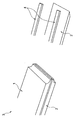
도 1은 정점 형태를 갖는 가열 장치를 개략적으로 도시하는 가열 장치의 부분의 확대도.
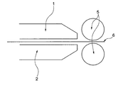
도 2는 캘린더 롤 및 시트를 갖는 가열 장치의 개략 측면도.
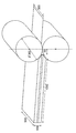
도 3은 가열 장치의 예를 개략적으로 도시하는 도면.1 is an enlarged view of a portion of a heating device schematically showing a heating device having a vertex form;
2 is a schematic side view of a heating apparatus having a calender roll and a sheet;
3 is a diagram schematically showing an example of a heating device.
도 1은 제 1 가열면(1) 및 제 2 가열면(2)을 갖는 가열 장치(3)를 개략적으로 도시한다. 제 1 가열면(1)은 제 2 가열면(2)의 상부에 배열되고, 양 가열면(1, 2)은 가열면(1, 2)의 적어도 하나의 단부 상에 정점 형태를 갖는다. 또한, 도 1에는 가열 장치(3)의 부분[제 2 가열면(2) 및 안내 요소(4)]의 분해도가 도시되어 있다. 이 상세한 도면에서, 2개의 안내 요소(4)가 도시되어 있다. 안내 요소(4)는 가열면(1, 2) 사이에 배열된다. 바람직하게는, 2개의 안내 요소(4) 중 적어도 하나는 가열면(1, 2) 중 하나와 대략 동일한 길이를 나타낸다. 도 1의 실시예에서, 양 안내 요소(4)는 제 1 및 제 2 가열면(1, 2)과 동일한 길이를 갖는다. 제 1 및 제 2 가열면(1, 2)은 가열 가능하고 또한 안내 요소(4)를 가열한다. 따라서, 가열면(1, 2) 및 또한 안내 요소(4)는 대략 동일한 온도를 나타낸다. 안내 요소(4)는 독립적인 가열원을 갖고, 이에 의해 가열 요소(4) 및 가열면(1, 2)의 온도가 서로에 대해 동일하거나 상이할 수 있는 것도 또한 가능하다. 도 1에 도시된 실시예에서, 제 1 가열면(1), 제 2 가열면(2) 및 각각의 안내 요소(4)는 가열 장치(3)의 개별 구성 요소이다. 제 1 가열면(1), 제 2 가열면(2) 및 각각의 안내 요소(4)는 단일편 가열 장치(3)를 구성하는 것도 또한 가능하다. 또한, 가열면(1, 2) 중 하나 및 가열 요소(4) 중 하나는 단일편인 것도 또한 가능하다. 안내 요소(4) 및 가열면(1, 2)에 기인하여, 터널이 형성된다. 이 터널 내부에는 시트(6)(도 1에는 도시되어 있지 않음)가 안내되고 또한 가열된다. 생성된 터널은 시트의 폭보다 단지 약간 더 큰 폭을 갖는다. 상이한 시트폭에 대해, 터널은 안내 요소(4)를 경유하여 조정될 수 있다. 일 예에서, 상이한 폭을 갖는 상이한 안내 요소(4)(및 단일편 안내 요소 및 가열면의 경우에 가열면)가 가열 장치(3)를 위해 사용될 수 있다. 다른 실시예에서, 안내 요소(4)는 가열 장치(3) 내부에 이동 가능하게 배열된다. 더 큰 폭을 갖는 터널이 필요하면, 안내 요소(4)는 가열면(1, 2) 위로 돌출될 것이고, 더 소형의 터널의 경우에 안내 요소(4)는 가열 장치(3) 내부에 가열면(1, 2)의 측면에 대해 더 큰 거리를 갖고 배열될 것이다. 제 1 가열면(1) 및 제 2 가열면(2)은 편평한 가열면 및 가열면의 일 단부에 정점 형태의 모두를 갖는다(도 1에 도시된 실시예에서). 정점 형태는 가열면 자체의 두께의 감소에 의해 발생하고 가열면의 편평한 형태에 영향을 미치지 않는다.1 schematically shows a
도 2에서, 가열 장치(3)가 한 쌍의 캘린더 롤(5)과 조합하여 도시되어 있다. 제 1 및 제 2 가열면(1, 2)의 정점 형태에 기인하여, 가열 장치(2)와 캘린더 롤(5) 사이의 거리는 작다. 시트(6)가 안내되고 가열될 수 있고 가열 장치(3)를 나온 직후에 캘린더 롤에 진입한다. 이에 기인하여, 시트(6)는 캘린더 롤(5)에 관하여 규정된 위치 또는 배열로 그리고 규정된 온도를 갖고 캘린더 롤(5)에 진입한다. 가열 장치(3)와 캘린더 롤(5) 사이의 장거리(분위기 온도에 따른)에 기인하는 온도 감소가 회피된다. 따라서, 프로세스는 높은 정확도로 반복 가능하다. 이에 부가하여, 시트는 항상 동일한 위치에서 캘린더 롤에 진입하는데 - 이는 시트가 항상 캘린더의 동일한 가압점을 가압하는 것을 의미한다. 따라서, 캘린더의 상이한 압력 편차가 보상된다. 캘린더 내부의 시트의 안정한 위치는 롤 간극의 안정성을 향상시키는데, 이는 시트 두께 편차를 감소시키고 롤링된 시트의 직선성을 향상시킨다.In FIG. 2, the
본 발명은 이하에 제공된 일 예에 의해 더 명료해진다.The present invention is further clarified by the examples provided below.
예 1Example 1
가열 장치는 제 1 및 제 2 가열면을 갖고, 각각의 가열면은 1000 mm의 길이 및 500 mm의 폭을 갖는다. 제 1 가열면은 제 2 가열면의 상부에 배열되고, 양 가열면은 함께 100 mm의 높이를 갖는다(제 1 및 제 2 가열면 사이의 간극을 포함하여). 가열면들은 100 내지 150℃의 범위, 바람직하게는 130 내지 140℃의 범위의 온도에서 가열 가능하다. 제 1 및 제 2 가열면의 일 단부에서, 가열면들은 정점형으로 성형되고, 이에 의해 제 1 및 제 2 가열면의 양 정점형 단부는 한 쌍의 캘린더 롤에 대면된다. 캘린더 롤은 300 mm의 직경을 갖고, 정점 형태의 단부는 양 캘린더 롤의 중심을 통해 수직으로 연장하는 라인에 대해 50 mm의 거리를 갖는다. 제 1 및 제 2 가열면 사이에는 2개의 안내 요소가 배열된다. 이들 안내 요소는 1000 mm의 길이 및 캘린더 롤에 대면된 정점 형태를 또한 갖는다. 제 1 가열면, 제 2 가열면 및 가열 요소는 채널을 형성하고, 이에 의해 채널의 모든 부분은 가열 가능하다. 시트가 채널 내부로 안내되고 300 mm의 폭을 갖는다. 가열 장치는 도 3에 개략적으로 도시되어 있다. 시트는 시트의 어떠한 수평 오프셋도 발생하지 않는 이러한 방식으로 채널 내부에 안내된다. 이는 제조 프로세스 중에 시트가 항상 동일한 위치에서 가열 장치를 떠나는 것을 의미한다.The heating device has first and second heating surfaces, each heating surface having a length of 1000 mm and a width of 500 mm. The first heating surface is arranged on top of the second heating surface, both heating surfaces together having a height of 100 mm (including the gap between the first and second heating surfaces). The heating surfaces are heatable at temperatures in the range of 100 to 150 ° C, preferably in the range of 130 to 140 ° C. At one end of the first and second heating surfaces, the heating surfaces are shaped into vertices, whereby both peaked ends of the first and second heating surfaces face a pair of calender rolls. The calender rolls have a diameter of 300 mm and the tip shaped ends have a distance of 50 mm with respect to the line extending vertically through the center of both calender rolls. Two guide elements are arranged between the first and second heating surfaces. These guide elements also have a length of 1000 mm and a vertex form facing the calendar roll. The first heating surface, the second heating surface and the heating element form a channel, whereby all parts of the channel are heatable. The sheet is guided into the channel and has a width of 300 mm. The heating device is shown schematically in FIG. 3. The sheet is guided inside the channel in this way without any horizontal offset of the sheet. This means that the sheet always leaves the heating device in the same position during the manufacturing process.
1: 제 1 가열면 2: 제 2 가열면
3: 가열 장치 4: 가열 요소
5: 캘린더 롤 6: 시트1: first heating surface 2: second heating surface
3: heating device 4: heating element
5: calendar roll 6: sheet
Claims (12)
적어도 2개의 안내 요소들(4)이 상기 제 1 및 제 2 가열면(1, 2) 사이에 배열되고 상기 제 1 및/또는 제 2 가열면(1, 2)은 적어도 하나의 단부에서 정점 형태를 갖는 것을 특징으로 하는 가열 장치(3).At least a first heating surface (1) and a second heating surface (2), wherein the first and second heating surfaces (1, 2) have the first and second heating surfaces (1, 2) In the heating device (3) for the sheet (6) arranged to be at the top,
At least two guide elements 4 are arranged between the first and second heating surfaces 1, 2 and the first and / or second heating surfaces 1, 2 are vertex-shaped at at least one end. Heating device (3) characterized in that it has a.
상기 제조 장치는 한 쌍의 캘린더 롤(5)을 포함하고, 제 1 및/또는 제 2 가열면(1, 2)이 상기 캘린더 롤들(5)에 대면하는 정점 형태를 갖고 배열되는 제조 장치.A manufacturing apparatus for sheets comprising the heating device (3) according to claim 1,
The manufacturing apparatus comprises a pair of calender rolls (5), wherein a first and / or second heating surface (1, 2) is arranged with a vertex shape facing the calender rolls (5).
Applications Claiming Priority (3)
| Application Number | Priority Date | Filing Date | Title |
|---|---|---|---|
| EP11151638.1 | 2011-01-21 | ||
| EP11151638 | 2011-01-21 | ||
| PCT/EP2012/050821 WO2012098210A1 (en) | 2011-01-21 | 2012-01-20 | Heating device |
Publications (1)
| Publication Number | Publication Date |
|---|---|
| KR20140049499A true KR20140049499A (en) | 2014-04-25 |
Family
ID=44246642
Family Applications (1)
| Application Number | Title | Priority Date | Filing Date |
|---|---|---|---|
| KR1020137021580A KR20140049499A (en) | 2011-01-21 | 2012-01-20 | Heating device |
Country Status (10)
| Country | Link |
|---|---|
| US (1) | US20130306619A1 (en) |
| EP (1) | EP2665590B1 (en) |
| JP (1) | JP6196161B2 (en) |
| KR (1) | KR20140049499A (en) |
| CN (1) | CN103338909A (en) |
| AU (1) | AU2012208523A1 (en) |
| BR (1) | BR112013018155A2 (en) |
| RU (1) | RU2013138744A (en) |
| TR (1) | TR201806681T4 (en) |
| WO (1) | WO2012098210A1 (en) |
Family Cites Families (25)
| Publication number | Priority date | Publication date | Assignee | Title |
|---|---|---|---|---|
| US1977666A (en) * | 1932-05-10 | 1934-10-23 | Western Electric Co | Repeater for rolling mills |
| GB555516A (en) * | 1942-03-06 | 1943-08-26 | Leslie Firth Bentley | Improved method and apparatus for heating material which has to be heated to perform a machining operation thereon |
| US2356998A (en) | 1942-03-27 | 1944-08-29 | Haniquet George | Towing attachment |
| US2370538A (en) * | 1943-02-24 | 1945-02-27 | Rca Corp | Cathode |
| GB621783A (en) * | 1945-07-19 | 1949-04-20 | British N S F Company Ltd | Improvements in means for heating insulating material prior to the working thereof |
| US2698260A (en) * | 1951-11-14 | 1954-12-28 | Balzaretti Modigliani Spa | Method of applying a bonding agent to mineral wool, excess removal, and drying thereof |
| US3066352A (en) * | 1957-08-30 | 1962-12-04 | Waldenstrom Sigurd | Machine for manufacturing fiberboards |
| US3658978A (en) * | 1969-07-07 | 1972-04-25 | Union Carbide Corp | Calendering of polymeric materials |
| JPS627485Y2 (en) * | 1980-11-17 | 1987-02-20 | ||
| DE3047784C2 (en) * | 1980-12-18 | 1982-10-21 | Forschungsgesellschaft für Biomedizinische Technik, 5100 Aachen | Method and device for heating suspensions or solutions frozen in a flat plastic bag |
| DE3325578C2 (en) * | 1983-07-15 | 1985-11-14 | Held, Kurt, 7218 Trossingen | Double belt press for the continuous production of laminates |
| JPS63132028A (en) * | 1986-11-25 | 1988-06-04 | Dainippon Printing Co Ltd | Manufacture of thermoplastic resin laminate with emboss effect |
| DE3734180C2 (en) * | 1987-10-09 | 1998-01-29 | Kuesters Eduard Maschf | Double belt press for the production of chipboard and the like |
| DE3914106A1 (en) | 1989-04-28 | 1990-10-31 | Siempelkamp Gmbh & Co | METHOD AND INSTALLATION FOR THE CONTINUOUS PRODUCTION OF CHIPBOARD, FIBERBOARD AND THE LIKE |
| US5316604A (en) * | 1990-12-04 | 1994-05-31 | Hexcel Corporation | Process for the preparation of thermoplastic sandwich structures |
| DE19517616A1 (en) * | 1995-05-13 | 1996-11-21 | Bosch Gmbh Robert | Device for connecting two packaging material webs |
| ATA142496A (en) * | 1996-08-07 | 2000-10-15 | Danubia Petrochem Polymere | DEVICE FOR HEATING FIBER REINFORCED THERMOPLASTICS BY MEANS OF HEAT CONTACT |
| US6297478B1 (en) * | 1998-08-25 | 2001-10-02 | Matsushita Electric Industrial Co., Ltd. | Thermal processing apparatus for a band film |
| DE19949662A1 (en) * | 1999-10-14 | 2001-04-19 | Dieffenbacher Gmbh Maschf | Prodn of board materials has a cooling station directly after the continuous hot press where water spray jets give a shock cooling action while the board material is held by a number of mangle rollers |
| TW576818B (en) * | 2001-11-30 | 2004-02-21 | Primax Electronics Ltd | Roller heating system for laminating machine and method for making roller shaft |
| US7487716B2 (en) * | 2002-02-19 | 2009-02-10 | Alto-Shaam, Inc. | Rotisserie oven |
| JP2004025530A (en) * | 2002-06-24 | 2004-01-29 | Canon Electronics Inc | Laminator |
| CN101081545A (en) * | 2006-05-30 | 2007-12-05 | 黄建龙 | Heating equipment of plastic sheet material |
| WO2008156663A2 (en) * | 2007-06-13 | 2008-12-24 | Fluxtrol Inc. | Magnetic flux guide for continuous high frequency welding of closed profiles |
| CN101774273B (en) * | 2010-02-12 | 2012-06-27 | 汕头市金兴机械有限公司 | All-in-one machine for vacuum forming, molding and punching |
-
2012
- 2012-01-20 WO PCT/EP2012/050821 patent/WO2012098210A1/en active Application Filing
- 2012-01-20 EP EP12700411.7A patent/EP2665590B1/en active Active
- 2012-01-20 AU AU2012208523A patent/AU2012208523A1/en not_active Abandoned
- 2012-01-20 CN CN2012800056877A patent/CN103338909A/en active Pending
- 2012-01-20 JP JP2013549815A patent/JP6196161B2/en active Active
- 2012-01-20 TR TR2018/06681T patent/TR201806681T4/en unknown
- 2012-01-20 BR BR112013018155A patent/BR112013018155A2/en not_active IP Right Cessation
- 2012-01-20 KR KR1020137021580A patent/KR20140049499A/en not_active Application Discontinuation
- 2012-01-20 US US13/980,958 patent/US20130306619A1/en not_active Abandoned
- 2012-01-20 RU RU2013138744/05A patent/RU2013138744A/en not_active Application Discontinuation
Also Published As
| Publication number | Publication date |
|---|---|
| EP2665590A1 (en) | 2013-11-27 |
| BR112013018155A2 (en) | 2019-09-24 |
| TR201806681T4 (en) | 2018-06-21 |
| RU2013138744A (en) | 2015-02-27 |
| AU2012208523A1 (en) | 2013-09-05 |
| CN103338909A (en) | 2013-10-02 |
| EP2665590B1 (en) | 2018-03-14 |
| US20130306619A1 (en) | 2013-11-21 |
| WO2012098210A1 (en) | 2012-07-26 |
| JP2014508667A (en) | 2014-04-10 |
| JP6196161B2 (en) | 2017-09-13 |
Similar Documents
| Publication | Publication Date | Title |
|---|---|---|
| CN107432054B (en) | Heating method, heating device, and method for producing press-molded article | |
| EP2774698B1 (en) | Press die | |
| KR101421978B1 (en) | Guide device for a strip rolling mill | |
| WO2013061480A1 (en) | Hot press molding method, article molded by hot press molding, and mold for hot pressing | |
| RU2438806C1 (en) | Method and device for hot rolling of magnesium | |
| KR20110013406A (en) | Method for producing deformed cross-section strip | |
| KR20140049499A (en) | Heating device | |
| CN104354466A (en) | Dual-purpose laser molding press with movable preheating roller | |
| CN105531107A (en) | Device and method for preventing warping of double-faced corrugated cardboard sheet and manufacturing apparatus for double-faced corrugated cardboard sheet | |
| MY187110A (en) | Method for manufacturing carrier tape for receiving electronic component | |
| KR20100004216A (en) | Metal tile manufacturing device | |
| CN204236010U (en) | A kind of dual-purpose type laser molding press that portable preheat roll is housed | |
| JP5619935B2 (en) | Thin glass manufacturing method and thin glass manufacturing apparatus | |
| KR101424472B1 (en) | Apparatus controlling temperature of steel | |
| US10286432B2 (en) | Continuous casting and rolling apparatus and method | |
| WO2010113836A1 (en) | Method for forming flat glass | |
| JP2017039225A (en) | Embossing device and embossing method | |
| KR101382180B1 (en) | Pre-heating device for hot stamping | |
| KR101498889B1 (en) | Device and method for synchronizing of slab sizing press | |
| JP4089511B2 (en) | Resin sheet rolling equipment | |
| KR101973878B1 (en) | Edging method and edging device | |
| JP6523703B2 (en) | Method and apparatus for manufacturing grooved metal sheet | |
| EP2248751B1 (en) | Procédé de correction d'une étendue de fente préselectionnée entre deux rouleaux de pliage | |
| JP6304498B2 (en) | Camber suppression method in hot slab sizing press | |
| KR20020052544A (en) | Blank roller guide position controlled device |
Legal Events
| Date | Code | Title | Description |
|---|---|---|---|
| WITN | Application deemed withdrawn, e.g. because no request for examination was filed or no examination fee was paid |