KR20140049314A - Stretchable electric device and manufacturing method of the same - Google Patents
Stretchable electric device and manufacturing method of the same Download PDFInfo
- Publication number
- KR20140049314A KR20140049314A KR1020120115432A KR20120115432A KR20140049314A KR 20140049314 A KR20140049314 A KR 20140049314A KR 1020120115432 A KR1020120115432 A KR 1020120115432A KR 20120115432 A KR20120115432 A KR 20120115432A KR 20140049314 A KR20140049314 A KR 20140049314A
- Authority
- KR
- South Korea
- Prior art keywords
- wiring
- layer
- forming
- photoresist pattern
- seed layer
- Prior art date
Links
- 238000004519 manufacturing process Methods 0.000 title abstract description 11
- 239000000758 substrate Substances 0.000 claims abstract description 35
- 238000000034 method Methods 0.000 claims description 47
- 229920002120 photoresistant polymer Polymers 0.000 claims description 38
- 238000009713 electroplating Methods 0.000 claims description 6
- VYPSYNLAJGMNEJ-UHFFFAOYSA-N Silicium dioxide Chemical compound O=[Si]=O VYPSYNLAJGMNEJ-UHFFFAOYSA-N 0.000 claims description 5
- 229910021420 polycrystalline silicon Inorganic materials 0.000 claims description 5
- 229920005591 polysilicon Polymers 0.000 claims description 5
- 229910052814 silicon oxide Inorganic materials 0.000 claims description 5
- 229910052581 Si3N4 Inorganic materials 0.000 claims description 4
- HQVNEWCFYHHQES-UHFFFAOYSA-N silicon nitride Chemical compound N12[Si]34N5[Si]62N3[Si]51N64 HQVNEWCFYHHQES-UHFFFAOYSA-N 0.000 claims description 4
- 230000008602 contraction Effects 0.000 claims description 3
- 229920000642 polymer Polymers 0.000 claims description 3
- 238000009413 insulation Methods 0.000 claims description 2
- 239000004205 dimethyl polysiloxane Substances 0.000 claims 1
- 235000013870 dimethyl polysiloxane Nutrition 0.000 claims 1
- CXQXSVUQTKDNFP-UHFFFAOYSA-N octamethyltrisiloxane Chemical compound C[Si](C)(C)O[Si](C)(C)O[Si](C)(C)C CXQXSVUQTKDNFP-UHFFFAOYSA-N 0.000 claims 1
- 238000004987 plasma desorption mass spectroscopy Methods 0.000 claims 1
- 229920000435 poly(dimethylsiloxane) Polymers 0.000 claims 1
- 238000000926 separation method Methods 0.000 claims 1
- 229910052751 metal Inorganic materials 0.000 description 10
- 239000002184 metal Substances 0.000 description 10
- 239000010949 copper Substances 0.000 description 7
- 238000000206 photolithography Methods 0.000 description 7
- RYGMFSIKBFXOCR-UHFFFAOYSA-N Copper Chemical compound [Cu] RYGMFSIKBFXOCR-UHFFFAOYSA-N 0.000 description 5
- 229910052802 copper Inorganic materials 0.000 description 5
- 238000005530 etching Methods 0.000 description 5
- 239000000463 material Substances 0.000 description 5
- 239000011651 chromium Substances 0.000 description 4
- 229920001971 elastomer Polymers 0.000 description 4
- 239000000806 elastomer Substances 0.000 description 4
- 239000010931 gold Substances 0.000 description 4
- 239000003960 organic solvent Substances 0.000 description 4
- 239000010936 titanium Substances 0.000 description 4
- 238000005137 deposition process Methods 0.000 description 3
- 239000004065 semiconductor Substances 0.000 description 3
- 238000004528 spin coating Methods 0.000 description 3
- VYZAMTAEIAYCRO-UHFFFAOYSA-N Chromium Chemical compound [Cr] VYZAMTAEIAYCRO-UHFFFAOYSA-N 0.000 description 2
- XUIMIQQOPSSXEZ-UHFFFAOYSA-N Silicon Chemical compound [Si] XUIMIQQOPSSXEZ-UHFFFAOYSA-N 0.000 description 2
- BQCADISMDOOEFD-UHFFFAOYSA-N Silver Chemical compound [Ag] BQCADISMDOOEFD-UHFFFAOYSA-N 0.000 description 2
- RTAQQCXQSZGOHL-UHFFFAOYSA-N Titanium Chemical compound [Ti] RTAQQCXQSZGOHL-UHFFFAOYSA-N 0.000 description 2
- 229910052782 aluminium Inorganic materials 0.000 description 2
- XAGFODPZIPBFFR-UHFFFAOYSA-N aluminium Chemical compound [Al] XAGFODPZIPBFFR-UHFFFAOYSA-N 0.000 description 2
- 229910052804 chromium Inorganic materials 0.000 description 2
- 239000011521 glass Substances 0.000 description 2
- PCHJSUWPFVWCPO-UHFFFAOYSA-N gold Chemical compound [Au] PCHJSUWPFVWCPO-UHFFFAOYSA-N 0.000 description 2
- 229910052737 gold Inorganic materials 0.000 description 2
- 238000007641 inkjet printing Methods 0.000 description 2
- 150000002739 metals Chemical class 0.000 description 2
- 238000007517 polishing process Methods 0.000 description 2
- 229910052710 silicon Inorganic materials 0.000 description 2
- 239000010703 silicon Substances 0.000 description 2
- 229910052709 silver Inorganic materials 0.000 description 2
- 239000004332 silver Substances 0.000 description 2
- 238000004544 sputter deposition Methods 0.000 description 2
- 239000000126 substance Substances 0.000 description 2
- 238000002207 thermal evaporation Methods 0.000 description 2
- 229910052719 titanium Inorganic materials 0.000 description 2
- WFKWXMTUELFFGS-UHFFFAOYSA-N tungsten Chemical compound [W] WFKWXMTUELFFGS-UHFFFAOYSA-N 0.000 description 2
- 229910052721 tungsten Inorganic materials 0.000 description 2
- 239000010937 tungsten Substances 0.000 description 2
- OKTJSMMVPCPJKN-UHFFFAOYSA-N Carbon Chemical compound [C] OKTJSMMVPCPJKN-UHFFFAOYSA-N 0.000 description 1
- LFQSCWFLJHTTHZ-UHFFFAOYSA-N Ethanol Chemical compound CCO LFQSCWFLJHTTHZ-UHFFFAOYSA-N 0.000 description 1
- 239000002041 carbon nanotube Substances 0.000 description 1
- 229910021393 carbon nanotube Inorganic materials 0.000 description 1
- 238000005229 chemical vapour deposition Methods 0.000 description 1
- 238000004891 communication Methods 0.000 description 1
- 230000000295 complement effect Effects 0.000 description 1
- 229920001940 conductive polymer Polymers 0.000 description 1
- 239000004020 conductor Substances 0.000 description 1
- 229910021389 graphene Inorganic materials 0.000 description 1
- 239000012535 impurity Substances 0.000 description 1
- 238000001465 metallisation Methods 0.000 description 1
- 238000000059 patterning Methods 0.000 description 1
- 238000005389 semiconductor device fabrication Methods 0.000 description 1
- 238000001039 wet etching Methods 0.000 description 1
Images


Classifications
-
- H—ELECTRICITY
- H01—ELECTRIC ELEMENTS
- H01L—SEMICONDUCTOR DEVICES NOT COVERED BY CLASS H10
- H01L23/00—Details of semiconductor or other solid state devices
- H01L23/52—Arrangements for conducting electric current within the device in operation from one component to another, i.e. interconnections, e.g. wires, lead frames
- H01L23/538—Arrangements for conducting electric current within the device in operation from one component to another, i.e. interconnections, e.g. wires, lead frames the interconnection structure between a plurality of semiconductor chips being formed on, or in, insulating substrates
-
- H—ELECTRICITY
- H05—ELECTRIC TECHNIQUES NOT OTHERWISE PROVIDED FOR
- H05K—PRINTED CIRCUITS; CASINGS OR CONSTRUCTIONAL DETAILS OF ELECTRIC APPARATUS; MANUFACTURE OF ASSEMBLAGES OF ELECTRICAL COMPONENTS
- H05K1/00—Printed circuits
- H05K1/02—Details
- H05K1/0277—Bendability or stretchability details
- H05K1/0283—Stretchable printed circuits
-
- H—ELECTRICITY
- H01—ELECTRIC ELEMENTS
- H01L—SEMICONDUCTOR DEVICES NOT COVERED BY CLASS H10
- H01L21/00—Processes or apparatus adapted for the manufacture or treatment of semiconductor or solid state devices or of parts thereof
- H01L21/70—Manufacture or treatment of devices consisting of a plurality of solid state components formed in or on a common substrate or of parts thereof; Manufacture of integrated circuit devices or of parts thereof
- H01L21/71—Manufacture of specific parts of devices defined in group H01L21/70
- H01L21/768—Applying interconnections to be used for carrying current between separate components within a device comprising conductors and dielectrics
- H01L21/76898—Applying interconnections to be used for carrying current between separate components within a device comprising conductors and dielectrics formed through a semiconductor substrate
-
- H—ELECTRICITY
- H01—ELECTRIC ELEMENTS
- H01L—SEMICONDUCTOR DEVICES NOT COVERED BY CLASS H10
- H01L23/00—Details of semiconductor or other solid state devices
- H01L23/52—Arrangements for conducting electric current within the device in operation from one component to another, i.e. interconnections, e.g. wires, lead frames
- H01L23/538—Arrangements for conducting electric current within the device in operation from one component to another, i.e. interconnections, e.g. wires, lead frames the interconnection structure between a plurality of semiconductor chips being formed on, or in, insulating substrates
- H01L23/5387—Flexible insulating substrates
-
- H—ELECTRICITY
- H01—ELECTRIC ELEMENTS
- H01L—SEMICONDUCTOR DEVICES NOT COVERED BY CLASS H10
- H01L29/00—Semiconductor devices adapted for rectifying, amplifying, oscillating or switching, or capacitors or resistors with at least one potential-jump barrier or surface barrier, e.g. PN junction depletion layer or carrier concentration layer; Details of semiconductor bodies or of electrodes thereof ; Multistep manufacturing processes therefor
- H01L29/66—Types of semiconductor device ; Multistep manufacturing processes therefor
- H01L29/68—Types of semiconductor device ; Multistep manufacturing processes therefor controllable by only the electric current supplied, or only the electric potential applied, to an electrode which does not carry the current to be rectified, amplified or switched
- H01L29/76—Unipolar devices, e.g. field effect transistors
- H01L29/772—Field effect transistors
- H01L29/78—Field effect transistors with field effect produced by an insulated gate
- H01L29/786—Thin film transistors, i.e. transistors with a channel being at least partly a thin film
- H01L29/78603—Thin film transistors, i.e. transistors with a channel being at least partly a thin film characterised by the insulating substrate or support
-
- H—ELECTRICITY
- H05—ELECTRIC TECHNIQUES NOT OTHERWISE PROVIDED FOR
- H05K—PRINTED CIRCUITS; CASINGS OR CONSTRUCTIONAL DETAILS OF ELECTRIC APPARATUS; MANUFACTURE OF ASSEMBLAGES OF ELECTRICAL COMPONENTS
- H05K1/00—Printed circuits
- H05K1/02—Details
-
- H—ELECTRICITY
- H05—ELECTRIC TECHNIQUES NOT OTHERWISE PROVIDED FOR
- H05K—PRINTED CIRCUITS; CASINGS OR CONSTRUCTIONAL DETAILS OF ELECTRIC APPARATUS; MANUFACTURE OF ASSEMBLAGES OF ELECTRICAL COMPONENTS
- H05K1/00—Printed circuits
- H05K1/18—Printed circuits structurally associated with non-printed electric components
-
- H—ELECTRICITY
- H01—ELECTRIC ELEMENTS
- H01L—SEMICONDUCTOR DEVICES NOT COVERED BY CLASS H10
- H01L2924/00—Indexing scheme for arrangements or methods for connecting or disconnecting semiconductor or solid-state bodies as covered by H01L24/00
- H01L2924/0001—Technical content checked by a classifier
- H01L2924/0002—Not covered by any one of groups H01L24/00, H01L24/00 and H01L2224/00
-
- H—ELECTRICITY
- H05—ELECTRIC TECHNIQUES NOT OTHERWISE PROVIDED FOR
- H05K—PRINTED CIRCUITS; CASINGS OR CONSTRUCTIONAL DETAILS OF ELECTRIC APPARATUS; MANUFACTURE OF ASSEMBLAGES OF ELECTRICAL COMPONENTS
- H05K2201/00—Indexing scheme relating to printed circuits covered by H05K1/00
- H05K2201/09—Shape and layout
- H05K2201/09209—Shape and layout details of conductors
- H05K2201/09654—Shape and layout details of conductors covering at least two types of conductors provided for in H05K2201/09218 - H05K2201/095
- H05K2201/097—Alternating conductors, e.g. alternating different shaped pads, twisted pairs; Alternating components
-
- H—ELECTRICITY
- H05—ELECTRIC TECHNIQUES NOT OTHERWISE PROVIDED FOR
- H05K—PRINTED CIRCUITS; CASINGS OR CONSTRUCTIONAL DETAILS OF ELECTRIC APPARATUS; MANUFACTURE OF ASSEMBLAGES OF ELECTRICAL COMPONENTS
- H05K3/00—Apparatus or processes for manufacturing printed circuits
- H05K3/46—Manufacturing multilayer circuits
- H05K3/4644—Manufacturing multilayer circuits by building the multilayer layer by layer, i.e. build-up multilayer circuits
Landscapes
- Engineering & Computer Science (AREA)
- Microelectronics & Electronic Packaging (AREA)
- Power Engineering (AREA)
- Physics & Mathematics (AREA)
- Condensed Matter Physics & Semiconductors (AREA)
- General Physics & Mathematics (AREA)
- Computer Hardware Design (AREA)
- Ceramic Engineering (AREA)
- Manufacturing & Machinery (AREA)
- Semiconductor Integrated Circuits (AREA)
- Micromachines (AREA)
- Internal Circuitry In Semiconductor Integrated Circuit Devices (AREA)
Abstract
Description
본 발명은 전자 디바이스 및 그의 제조방법에 관한 것으로, 보다 상세하게는 신축성 전자 디바이스 및 그의 제조방법에 관한 것이다. TECHNICAL FIELD The present invention relates to an electronic device and a method for manufacturing the same, and more particularly to a stretchable electronic device and a method for manufacturing the same.
신축성 전자 디바이스는 외부에서 작용하는 응력에 의해 기판이 확장(expended)되더라도 전기적인 기능을 그대로 유지할 수 있다. 신축성 전자 디바이스는 단순한 휨 (bendable) 및/또는 유연(flexible) 소자의 한계를 뛰어넘어 로봇용 센서 피부, wearable 통신 소자, 인체내장/부착형 바이오 소자, 차세대 디스플레이 등 다양한 분야의 응용 가능성을 가지고 있다. The elastic electronic device can maintain the electrical function even if the substrate is expended by an externally applied stress. Flexible electronic devices have the potential to be applied to various fields such as sensors for robots, wearable communication devices, built-in / attached bio-devices, and next generation displays, beyond the limitations of simple bendable and / or flexible devices .
종래의 신축성 전자 디바이스는 금속 배선의 확장이 가능한 구조를 가질 수 있다. 금속 배선은 미리 당겨진(pre-strained) 신축성 기판 표면에 전사된 뒤에 상기 신축성 기판의 수축에 의해 물결 모양으로 형성될 수 있다. 금속 배선은 전자 디바이스의 확장능력(stretchability)을 부여할 수 있다. 그러나, 종래의 신축 전자 디바이스는 초기에 기판에 가해진 pre-strain의 양에 의해 금속 배선의 확장능력이 제한될 수 있다. 또한, 물결 모양의 금속 배선은 일반적인 반도체 소자 제작공정에 비해 과정이 복잡하여 대면적 적용 및 신뢰성 확보가 어렵다는 단점을 갖는다.The conventional stretchable electronic device may have a structure in which metal wiring can be expanded. The metal wiring may be formed in a wavy form by shrinkage of the stretchable substrate after being transferred to a pre-strained stretchable substrate surface. The metallization can provide the stretchability of the electronic device. However, conventional stretchable electronic devices may be limited in their ability to expand metal wiring by the amount of pre-strain initially applied to the substrate. In addition, the wavy metal wiring has a disadvantage that it is difficult to apply a large area and secure reliability, because the process is complicated compared with a general semiconductor device fabrication process.
다른 종래의 신축성 전자 디바이스는 금속 대신 전도성을 갖는 신축성 소재의 배선을 포함할 수 있다. 전도성 신축 소재는 주로 전도성 고분자, 탄소나노튜브, 그래핀 등의 전도성 물질을 포함한다. 그러나, 전도성 신축 소재는 확장능력이 높은 반면 금속에 비해 전기저항이 높고 마이크로미터 수준의 미세 패터닝이 어렵다는 단점을 가질 수 있다Another conventional stretchable electronic device may include wiring of a stretchable material that is conductive instead of metal. Conductive stretching materials mainly include conductive materials such as conductive polymers, carbon nanotubes, and graphenes. However, the conductive stretchable material has a high expansion capability, but has a drawback that the electrical resistance is higher than that of the metal, and the fine patterning at the micrometer level is difficult
또 다른 종래의 신축성 전자 디바이스는 2차원 평면 스프링 모양의 배선을 포함할 수 있다. 스프링 모양의 배선은 배선제작 공정이 일반적인 반도체 소자 공정과 호환되어 비용 절감 및 신뢰성 확보가 용이하고, 높은 전도성을 가질 수 있다. 그러나, 스프링 모양의 배선은 신축될 때, 배선의 특정 부위에만 국부적으로 변형량이 집중되어 파손을 유발하므로 확장율을 높이는 데에 한계가 있다. Another conventional stretchable electronic device can include two-dimensional planar spring-shaped wiring. The spring-like wiring is compatible with a semiconductor device process, which is a general wiring process, so that cost reduction and reliability can be easily ensured and high conductivity can be obtained. However, when the spring-shaped wiring is elongated or contracted, the amount of deformation is locally concentrated only at a specific portion of the wiring, causing breakage. Therefore, there is a limit to increase the expansion rate.
본 발명이 이루고자 하는 기술적 과제는, 입체적 코일 배선을 갖는 신축성 전자 디바이스 및 그의 제조방법을 제공하는 데 있다.An object of the present invention is to provide a stretchable electronic device having a three-dimensional coil wiring and a manufacturing method thereof.
본 발명의 다른 과제는 코일 배선의 단선을 최소화 또는 제거할 수 있는 신축성 전자 디바이스 및 그의 제조방법을 제공하는 데 있다.Another object of the present invention is to provide a stretchable electronic device capable of minimizing or eliminating disconnection of a coil wiring and a method of manufacturing the same.
본 발명의 실시 예에 따른 신축성 전자 디바이스의 제조방법은, 제 1 기판 상에 코일 배선들을 형성하는 단계;상기 코일 배선을 덮는 제 1 신축 절연 층을 형성하는 단계; 상기 제 1 신축 절연 층 상에 제 2 기판을 형성하는 단계; 상기 코일 배선 및 상기 제 1 신축 절연 층으로부터 상기 제 1 기판을 분리하는 단계; 및 상기 코일 배선 상에 트랜지스터를 형성하는 단계를 포함한다.A method of manufacturing a stretchable electronic device according to an embodiment of the present disclosure may include forming coil wires on a first substrate; forming a first stretchable insulating layer covering the coil wires; Forming a second substrate on the first stretchable insulating layer; Separating the first substrate from the coil wiring and the first stretchable insulating layer; And forming a transistor on the coil wiring.
본 발명의 일 실시 예에 따르면, 상기 코일 배선의 형성 단계는, 상기 제 1 기판 상에 희생 층을 형성하는 단계; 상기 희생 층 상에 제 1 배선들을 형성하는 단계; 상기 제 1 배선들 상에 기둥 배선들을 형성하는 단계; 및 상기 기둥 배선들 상에 제 2 배선들을 형성하는 단계를 포함할 수 있다.According to an embodiment of the present disclosure, the forming of the coil wiring may include forming a sacrificial layer on the first substrate; Forming first wirings on the sacrificial layer; Forming pillar wirings on the first wirings; And forming second wires on the pillar wires.
본 발명의 다른 실시 예에 따르면, 상기 희생 층은 포토레지스트, 폴리 실리콘, 실리콘 산화막, 또는 실리콘 질화막을 포함할 수 있다.According to another embodiment of the present invention, the sacrificial layer may include a photoresist, polysilicon, a silicon oxide film, or a silicon nitride film.
본 발명의 일 실시 예에 따르면, 상기 제 1 기판의 분리 단계는, 상기 희생 층을 제거하는 단계를 포함할 수 있다.According to an embodiment of the present disclosure, the separating of the first substrate may include removing the sacrificial layer.
본 발명의 다른 실시 예에 따르면, 상기 제 1 배선들의 형성 단계는, 상기 희생 층 상에 제 1 씨드 층을 형성하는 단계; 상기 제 1 씨드 층의 일부 상에 제 1 포토레지스트 패턴을 형성하는 단계; 및 상기 제 1 포토레지스트 패턴에 의해 노출되는 상기 제 1 씨드 층 상에 제 1 캡 배선 층을 형성하는 단계를 포함할 수 있다.According to another embodiment of the present disclosure, the forming of the first interconnections may include forming a first seed layer on the sacrificial layer; Forming a first photoresist pattern on a portion of the first seed layer; And forming a first cap line layer on the first seed layer exposed by the first photoresist pattern.
본 발명의 일 실시 예에 따르면, 상기 제 1 캡 배선 층은 전해 도금 방법으로 형성될 수 있다. According to one embodiment of the present invention, the first cap wiring layer may be formed by an electroplating method.
본 발명의 다른 실시 예에 따르면, 상기 기둥 배선들의 형성 단계는, 상기 제 1 캡 배선 층의 일부와, 상기 제 1 씨드 층 상에 제 2 포토레지스트 패턴 층을 형성하는 단계; 및 상기 제 1 캡 배선 층 상에 기둥 배선을 형성하는 단계를 포함할 수 있다.According to another embodiment of the present disclosure, the forming of the pillar wirings may include forming a portion of the first cap wiring layer and a second photoresist pattern layer on the first seed layer; And forming pillar wirings on the first cap wiring layer.
본 발명의 일 실시 예에 따르면, 상기 제 2 배선의 형성 단계는, 상기 기둥 배선 및 상기 제 2 포토레지스트 패턴 상에 제 2 씨드 층을 형성하는 단계; 상기 제 2 씨드 층의 일부에 제 3 포토 레지스트 패턴을 형성하는 단계; 및 상기 제 3 포토레지스트 패턴으로부터 노출되는 상기 제 2 씨드 층 상에 제 2 캡 배선 층을 형성하는 단계를 포함할 수 있다.According to an embodiment of the present disclosure, the forming of the second wiring may include forming a second seed layer on the pillar wiring and the second photoresist pattern; Forming a third photoresist pattern on a portion of the second seed layer; And forming a second cap interconnection layer on the second seed layer exposed from the third photoresist pattern.
본 발명의 다른 실시 예에 따르면, 상기 코일 배선의 형성 단계는, 상기 제 3 포토 레지스트 패턴과, 상기 제 2 캡 배선 층으로부터 노출되는 상기 제 2 씨드 층을 제거하는 단계를 더 포함할 수 있다. 상기 제 2 씨드 층은 식각될 수 있다.According to another embodiment of the present disclosure, the forming of the coil wiring may further include removing the third photoresist pattern and the second seed layer exposed from the second cap wiring layer. The second seed layer may be etched.
본 발명의 일 실시 예에 따르면, 상기 코일 배선의 형성 단계는, 상기 제 2 포토 레지스트 패턴과, 상기 제 1 캡 배선 층으로부터 노출되는 상기 제 1 씨드 층을 제거하는 단계를 더 포함할 수 있다. 상기 제 1 씨드 층은 식각될 수 있다.According to an embodiment of the present disclosure, the forming of the coil wiring may further include removing the second photoresist pattern and the first seed layer exposed from the first cap wiring layer. The first seed layer may be etched.
본 발명의 다른 실시 예에 따르면, 상기 트랜지스터의 형성 후에, 제 2 신축성 절연 층을 형성하는 단계; 및 상기 제 2 기판을 제거하는 단계를 더 포함할 수 있다.According to another embodiment of the present invention, after forming the transistor, forming a second stretchable insulating layer; And removing the second substrate.
본 발명의 다른 실시 예에 따른 신축성 전자 디바이스는, 신축 절연 층; 상기 신축 절연 층 내의 트랜지스터들; 및 상기 트랜지스터들 사이에 지그재그로 연결되고 상기 신축 절연 층의 수축 또는 팽창에 의해 신축(stretched)되는 배선을 포함한다.According to another exemplary embodiment, a stretchable electronic device may include a stretchable insulating layer; Transistors in the stretchable insulating layer; And wires zigzag connected between the transistors and stretched by contraction or expansion of the stretchable insulating layer.
본 발명의 일 실시 예에 따르면, 상기 신축 절연 층은 탄성 중합체를 포함할 수 있다.According to one embodiment of the present invention, the stretchable insulating layer may include an elastomer.
본 발명의 다른 실시 예에 따르면, 상기 탄성 중합체는 피디엠에스(PDMS)를 포함할 수 있다.According to another embodiment of the present invention, the elastomeric polymer may include PDMS.
본 발명의 일 실시 예에 따르면, 상기 배선은 코일 배선을 포함할 수 있다.According to an embodiment of the present disclosure, the wiring may include a coil wiring.
본 발명의 다른 실시 예에 따르면, 상기 코일 배선은, 제 1 배선; 상기 제 1 배선 상에 형성된 기둥 배선; 및 상기 기둥 배선 상에 형성된 제 2 배선을 포함할 수 있다.According to another embodiment of the present invention, the coil wiring includes: a first wiring; Pillar wiring formed on the first wiring; And a second wiring formed on the pillar wiring.
본 발명의 일 실시 예에 따르면, 상기 제 1 배선은 제 1 씨드 층과 제 1 캡 배선 층을 포함하고, 상기 제 2 배선은 제 2 씨드 층과 제 2 캡 배선 층을 포함할 수 있다.According to an embodiment of the present disclosure, the first wiring may include a first seed layer and a first cap wiring layer, and the second wiring may include a second seed layer and a second cap wiring layer.
본 발명의 실시 예에 따른 신축성 전자 디바이스는 트랜지스터와, 코일 배선과, 신축 절연 층을 포함할 수 있다. 트랜지스터와 코일 배선은 신축 절연 층 내에 배치된다. 코일 배선은 포토리소그래피 공정 및 전해도금방법에 의해 입체적으로 형성될 수 있다. 코일 배선은 하부 배선들, 상부 배선들, 및 기둥 배선들을 포함할 수 있다. 상부 배선들과 하부 배선들은 지그 재그 모양으로 연장될 수 있다. 지그 재그 모양의 코일 배선은 신축 절연 층의 수축 팽창 시에 변형의 집중 현상이 억제될 수 있다. 따라서, 본 발명의 실시 예에 따른 신축성 전자 디바이스는 코일 배선의 단선을 최소화 또는 제거할 수 있다.A stretchable electronic device according to an embodiment of the present invention may include a transistor, a coil wiring, and a stretchable insulating layer. The transistor and coil wiring are disposed in the stretchable insulating layer. The coil wiring may be three-dimensionally formed by a photolithography process and an electroplating method. The coil wiring may include lower wirings, upper wirings, and pillar wirings. The upper wires and the lower wires may extend in a zigzag shape. The zig-zag coil wiring can suppress the concentration of deformation during shrinkage expansion of the stretchable insulating layer. Therefore, the stretchable electronic device according to the embodiment of the present invention can minimize or eliminate the disconnection of the coil wiring.
도 1은 본 발명의 실시 예에 따른 신축성 전자 디바이스를 개략적으로 나타내는 사시도이다.
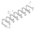
도 2는 도 1의 코일 배선을 나타낸 사시도이다.
도 3은 도 1의 단면도이다.
도 4 내지 도 21은 도 3에 근거한 본 발명의 실시 예에 따른 신축성 전자 디바이스의 제조방법을 나타낸 공정 단면도들이다.1 is a perspective view schematically illustrating a stretchable electronic device according to an embodiment of the present disclosure.
FIG. 2 is a perspective view illustrating the coil wiring of FIG. 1. FIG.
3 is a cross-sectional view of Fig.
4 to 21 are cross-sectional views illustrating a method of manufacturing a stretchable electronic device according to an embodiment of the present disclosure based on FIG. 3.
앞의 일반적인 설명 및 다음의 상세한 설명들은 모두 청구된 발명의 부가적인 설명을 제공하기 위한 예시적인 것이다. 그러므로 본 발명은 여기서 설명되는 실시 예에 한정되지 않고 다른 형태로 구체화될 수도 있다. 여기서 소개되는 실시 예는 개시된 내용이 철저하고 완전해 질 수 있도록 그리고 당업자에게 본 발명의 사상이 충분히 전달될 수 있도록 하기 위해 제공되는 것이다. The foregoing general description and the following detailed description are exemplary and are intended to provide further explanation of the claimed invention. Therefore, the present invention is not limited to the embodiments described herein but may be embodied in other forms. The embodiments disclosed herein are provided so that the disclosure can be thorough and complete, and will fully convey the scope of the invention to those skilled in the art.
본 명세서에서, 어떤 부분이 어떤 구성요소를 포함한다고 언급되는 경우에, 이는 그 외의 다른 구성요소를 더 포함할 수도 있다는 것을 의미한다. 또한, 여기에서 설명되고 예시되는 각 실시 예는 그것의 상보적인 실시 예도 포함한다. 이하, 본 발명의 실시 예를 첨부된 도면을 참조하여 상세하게 설명한다.In this specification, when it is mentioned that a certain element includes an element, it means that it may further include other elements. In addition, each embodiment described and illustrated herein includes its complementary embodiment. DETAILED DESCRIPTION OF THE PREFERRED EMBODIMENTS Hereinafter, embodiments of the present invention will be described in detail with reference to the accompanying drawings.
도 1은 본 발명의 실시 예에 따른 신축성 전자 디바이스를 개략적으로 나타내는 사시도이다. 도 2는 도 1의 코일 배선을 나타낸 사시도이다. 도 3은 도 1의 단면도이다.1 is a perspective view schematically illustrating a stretchable electronic device according to an embodiment of the present disclosure. FIG. 2 is a perspective view illustrating the coil wiring of FIG. 1. FIG. 3 is a cross-sectional view of Fig.
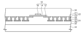
도 1 내지 도 3을 참조하면, 본 발명의 실시 예에 따른 신축성 전자 디바이스는 트랜지스터(10), 코일 배선(20) 및 신축 절연 층(30)을 포함할 수 있다.1 to 3, a stretchable electronic device according to an embodiment of the present disclosure may include a
트랜지스터(10) 및 코일 배선(20)은 신축 절연 층(30) 내에 배치될 수 있다. 트랜지스터(10)는 활성 층(12), 게이트 절연막(14) 및 게이트 전극(16)을 포함할 수 있다. 활성 층(12)은 코일 배선(20)에 연결될 수 있다. 도시되지는 않았지만, 활성 층(12)은 코일 배선(20) 상의 소스/드레인 영역을 가질 수 있다. 소스/드레인 영역은 도전성 불순물로 도핑될 수 있다. 게이트 절연막(14)은 활성 층(12)을 덮는다. 게이트 전극(16)은 활성 층(12)에 오버랩(overlap)된다. The
코일 배선(20)은 신축 절연 층(30) 내에서 신장(stretchable)될 수 있다. 코일 배선(20)은 하부 배선(24), 기둥 배선(28), 및 상부 배선(22)을 포함할 수 있다. 하부 배선(24), 기둥 배선(28) 상부 배선(22)은 입체적(three dimensional)으로 연결될 수 있다. 기둥 배선(28)은 하부 배선(24) 및 상부 배선(22)을 연결할 수 있다. 하부 배선(24) 및 상부 배선(22)은 지그재그로 연장될 수 있다. 신축 절연 층(30)이 신축될 때, 하부 배선(24) 및 상부 배선(22)은 균일하게 신축(stretched)될 수 있다. 코일 배선(20)은 국부적인 변형 집중 현상이 방지될 수 있다. 따라서, 본 발명의 실시 예에 따른 신축성 전자 디바이스는 코일 배선(20)의 단선(open)을 최소화 또는 제거할 수 있다. The
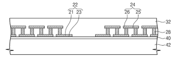
하부 배선(24)은 하부 씨드 층(25) 및 하부 캡 배선 층(26)을 포함할 수 있다. 상부 배선(22)은 상부 씨드 층(21) 및 상부 캡 배선 층(23)을 포함할 수 있다. 기둥 배선(28)은 상부 캡 배선 층(23)과 하부 씨드 층(25) 사이에 연결될 수 있다. The
신축 절연 층(30)은 코일 배선(20)을 신축 가능하게 할 수 있다. 코일 배선(20)은 신축 절연 층(30)의 팽창 또는 수축에 의해 신축(stretched)될 수 있다. 신축 절연 층(30)은 외부의 인장응력(tensile stress)에 의해 탄성 변형될 수 있다. 신축 절연 층(30)은 PDMS(Poly-Dimethyllesiloxane)와 같은 탄성 중합체를 포함할 수 있다. The stretchable insulating
이와 같이 구성된 본 발명의 실시 예에 따른 신축성 전자 디바이스의 제조 방법을 설명하면 다음과 같다.The manufacturing method of the stretchable electronic device according to the exemplary embodiment of the present invention configured as described above is as follows.
도 4 내지 도 21은 도 3에 근거한 본 발명의 실시 예에 따른 신축성 전자 디바이스의 제조방법을 나타낸 공정 단면도들이다. 4 to 21 are cross-sectional views illustrating a method of manufacturing a stretchable electronic device according to an embodiment of the present disclosure based on FIG. 3.
도 4를 참조하면, 제 1 기판(42) 상에 희생 층(40) 및 상부 씨드 층(21)을 형성한다. 제 1 기판(42)은 실리콘 웨이퍼 또는 글래스와 같은 평판 기판을 포함할 수 있다. 희생 층(40)은 스핀 코팅으로 형성된 포토레지스트, 폴리 실리콘, 실리콘 산화막 또는 실리콘 질화막을 포함할 수 있다. 상부 씨드 층(21)은 금(Au), 은(Ag), 구리(Cu), 알미늄(Al), 텅스텐(W), 타이타늄(Ti), 크롬(Cr)과 같은 금속을 포함한다. 금속은 스퍼터링 방법 또는 열증착 방법으로 형성될 수 있다.Referring to FIG. 4, a
도 5를 참조하면, 상부 씨드 층(21) 상에 제 1 포토레지스트 패턴(52)을 형성한다. 제 1 포토레지스트 패턴(52)은 일반적인 포토리소그래피 공정으로 형성될 수 있다.Referring to FIG. 5, a
도 6을 참조하면, 제 1 포토레지스트 패턴(52)으로부터 노출된 상부 씨드 층(21) 상에 상부 캡 배선 층(23)을 형성한다. 상부 씨드 층(21)은 전해 도금 방법으로 형성된 구리를 포함할 수 있다. 이후, 제 1 포토레지스트 패턴(52)는 제거될 수 있다. Referring to FIG. 6, the upper
도 7을 참조하면, 상부 캡 배선 층(23)의 일부와 제 1 포토레지스트 패턴(52) 상(위에서 이미 제거됨)에 제 2 포토레지스트 패턴(54)을 형성한다. 제 2 포토레지스트 패턴(54)은 제 1 포토레지스트 패턴(52)와 동일한 포토리소그래피 공정으로 형성될 수 있다. 제 2 포토레지스트 패턴(54)은 콘택 홀(53)을 가질 수 있다. 콘택 홀(53)은 상부 캡 배선 층(23)을 노출시킬 수 있다. Referring to FIG. 7, a
도 8을 참조하면, 콘택 홀(53) 내에 기둥 배선(28)을 형성한다. 기둥 배선(28)은 상부 캡 배선 층(23) 상에 형성될 수 있다. 기둥 배선(28)은 전해 도금 방법으로 형성된 구리를 포함할 수 있다. Referring to FIG. 8, pillar wirings 28 are formed in the contact holes 53. The
도 9를 참조하면, 기둥 배선(28) 및 제 2 포토레지스트 패턴(54) 상에 하부 씨드 층(25)을 형성한다. 하부 씨드 층(25)은 스퍼터링 방법 또는 열증착 방법으로 형성될 수 있다. 하부 씨드 층(25)은 금(Au), 은(Ag), 구리(Cu), 알미늄(Al), 텅스텐(W), 타이타늄(Ti), Cr(크롬)과 같은 금속을 포함할 수 있다.Referring to FIG. 9, the
도 10을 참조하면, 하부 씨드 층(25) 상의 일부에 제 3 포토레지스트 패턴(56)을 형성한다. 제 3 포토레지스트 패턴(56)은 포토리소그래피 공정으로 형성될 수 있다.Referring to FIG. 10, a
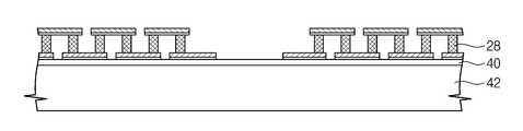
도 11을 참조하면, 제 3 포토레지스트 패턴(56)에 의해 노출된 하부 씨드 층(25) 상에 하부 캡 배선 층(26)을 형성한다. 하부 캡 배선 층(26)은 전해 도금 방법으로 형성된 구리를 포함할 수 있다.Referring to FIG. 11, a lower
도 12를 참조하면, 제 3 포토레지스트 패턴(56)과, 하부 씨드 층(25)의 일부를 제거한다. 제 3 포토레지스트 패턴(56)은 유기 용매에 의해 제거될 수 있다. 유기 용매는 휘발성이 높은 알코올을 포함할 수 있다. 하부 캡 배선 층(26)으로부터 노출된 하부 씨드 층(25)은 식각 공정에 의해 제거될 수 있다. Referring to FIG. 12, a portion of the
도 13을 참조하면, 제 2 포토레지스트 패턴(54)과, 상부 씨드 층(21)의 일부를 제거한다. 제 2 포토레지스트 패턴(54)은 유기 용매에 의해 제거될 수 있다. 상부 캡 배선 층(23)으로부터 노출된 상부 씨드 층(21)은 식각 공정에 의해 제거될 수 있다. Referring to FIG. 13, a portion of the
도 2 및 도 14를 참조하면, 코일 배선(20)을 덮는 하부 신축 절연 층(32)을 형성한다. 하부 신축 절연 층(32)은 PDMS(Poly-Dimethyllesiloxane)과 같은 탄성 중합체를 포함할 수 있다. 하부 신축 절연 층(32)은 코일 배선(20)을 매립할 수 있다.2 and 14, the lower
도 15를 참조하면, 하부 신축 절연 층(32) 상에 제 2 기판(44)을 형성한다. 제 2 기판(44)은 실리콘 웨이퍼, 플라스틱 기판, 또는 글래스를 포함할 수 있다. Referring to FIG. 15, a
도 16을 참조하면, 희생 층(40)을 제거하여 상부 배선(22) 및 하부 신축 절연 층(32)으로부터 제 1 기판(42)을 분리한다. 희생 층(40)은 포토레지스트 층일 때, 유기 용매에 의해 제거될 수 있다. 희생 층(40)은 실리콘 산화막일 때, 제 1 기판(42)의 제거 후에 습식 식각 공정으로 제거될 수 있다. 제 1 기판(42)은 화학적기계적 연마공정에 의해 제거될 수 있다. 도시되지 않았지만, 상부 씨드 층(21)은 기판의 전면에서 제거될 수 있다. 코일 배선(20)과 하부 신축 절연 층(32)은 제 2 기판(44)에 전이될 수 있다. Referring to FIG. 16, the
도 2 및 도 17을 참조하면, 제 2 기판(44), 코일 배선(20)을 뒤집는다. 상부 배선(22)의 상부 씨드 층(21)이 제 2 기판(44) 상에 배치될 수 있다. 2 and 17, the
도 18을 참조하면, 상부 배선들(22) 및 상기 상부 배선들(22) 사이의 하부 신축 절연 층(32) 상에 활성 층(12)을 형성한다. 활성 층(12)은 폴리 실리콘, 유기반도체 물질을 포함할 수 있다. 폴리 실리콘은 화학기상증착 공정, 포토리소그래피 공정 및 식각 공정에 의해 형성될 수 있다. 유기반도체 물질은 잉크젯 프린팅, 스핀코팅 등의 공정에 의해 형성될 수 있다.Referring to FIG. 18, the
도 19를 참조하면, 활성 층(12) 상에 게이트 절연막(14)을 형성한다. 게이트 절연막(14)은 실리콘 산화막 또는 실리콘 질화막, 유기 절연막 등을 포함할 수 있다. 게이트 절연막(14)은 증착 공정, 포토리소그래피 공정 및 식각 공정, 잉크젯 프린팅, 스핀 코팅에 의해 형성될 수 있다. Referring to FIG. 19, a
도 20을 참조하면, 게이트 절연막(14) 상에 게이트 전극(16)을 형성한다. 게이트 전극(16)은 도전성 금속을 포함할 수 있다. 게이트 전극은 증착 공정, 포토리소그래피 공정 및 식각 공정, shadow 마스크를 통한 증착 공정에 의해 형성될 수 있다. Referring to FIG. 20, a
도 21를 참조하면, 트랜지스터(10) 및 코일 배선(20) 상에 상부 신축 절연 층(34)을 형성한다. 상부 신축 절연 층(34)은 PDMS와 같은 탄성 중합체를 포함할 수 있다. Referring to FIG. 21, an upper stretchable insulating
도 22를 참조하면, 하부 신축 절연 층(32)으로부터 제 2 기판(44)을 분리한다. 제 2 기판(44)은 외력에 의해 하부 신축 절연 층(32)으로부터 제거 또는 박리될 수 있다. 또한, 제 2 기판(44)은 화학적 기계적 연마 공정에 의해 제거될 수 있다.Referring to FIG. 22, the
이제까지 본 발명에 대하여 그 바람직한 실시 예들을 중심으로 살펴보았다. 본 발명이 속하는 기술 분야에서 통상의 지식을 가진 자는 본 발명이 본 발명의 본질적인 특성성에서 벗어나지 않는 범위에서 변형된 형태로 구현될 수 있음을 이해할 수 있을 것이다. 그러므로 개시된 실시 예들은 한정적인 관점이 아니라 설명적인 관점에서 고려되어야 한다. 본 발명의 범위는 전술한 설명이 아니라 특허청구범위에 나타나 있으며, 그와 동등한 범위 내에 있는 모든 차이점은 본 발명에 포함된 것으로 해석되어야 할 것이다.The present invention has been described with reference to the preferred embodiments. It will be understood by those of ordinary skill in the art that various changes in form and details may be made therein without departing from the spirit and scope of the invention as defined by the appended claims. Therefore, the disclosed embodiments should be considered in an illustrative rather than a restrictive sense. The scope of the present invention is defined by the appended claims rather than by the foregoing description, and all differences within the scope of equivalents thereof should be construed as being included in the present invention.
10: 트랜지스터 20: 코일 배선
30: 신축 절연 층 40: 희생 층10: transistor 20: coil wiring
30: stretch insulation layer 40: sacrificial layer
Claims (20)
상기 코일 배선을 덮는 제 1 신축 절연 층을 형성하는 단계;
상기 제 1 신축 절연 층 상에 제 2 기판을 형성하는 단계;
상기 코일 배선 및 상기 제 1 신축 절연 층으로부터 상기 제 1 기판을 분리하는 단계; 및
상기 코일 배선 상에 트랜지스터를 형성하는 단계를 포함하는 신축성 전자 디바이스의 제조방법.Forming coil wirings on the first substrate;
Forming a first stretchable insulating layer covering the coil wiring;
Forming a second substrate on the first stretchable insulating layer;
Separating the first substrate from the coil wiring and the first stretchable insulating layer; And
Forming a transistor on the coil wiring.
상기 코일 배선의 형성 단계는,
상기 제 1 기판 상에 희생 층을 형성하는 단계;
상기 희생 층 상에 제 1 배선들을 형성하는 단계;
상기 제 1 배선들 상에 기둥 배선들을 형성하는 단계; 및
상기 기둥 배선들 상에 제 2 배선들을 형성하는 단계를 포함하는 신축성 전자 디바이스의 제조방법.The method according to claim 1,
Forming the coil wiring,
Forming a sacrificial layer on the first substrate;
Forming first wirings on the sacrificial layer;
Forming pillar wirings on the first wirings; And
Forming second wirings on the pillar wirings.
상기 희생 층은 포토레지스트, 폴리 실리콘, 실리콘 산화막, 또는 실리콘 질화막을 포함하는 신축성 전자 디바이스의 제조방법.3. The method of claim 2,
And the sacrificial layer comprises a photoresist, polysilicon, silicon oxide film, or silicon nitride film.
상기 제 1 기판의 분리 단계는,
상기 희생 층을 제거하는 단계를 포함하는 신축성 전자 디바이스의 제조방법.3. The method of claim 2,
Separation of the first substrate,
Removing the sacrificial layer.
상기 제 1 배선들의 형성 단계는,
상기 희생 층 상에 제 1 씨드 층을 형성하는 단계;
상기 제 1 씨드 층의 일부 상에 제 1 포토레지스트 패턴을 형성하는 단계; 및
상기 제 1 포토레지스트 패턴에 의해 노출되는 상기 제 1 씨드 층 상에 제 1 캡 배선 층을 형성하는 단계를 포함하는 단계를 포함하는 신축성 전자 디바이스의 제조방법.5. The method of claim 4,
Forming the first wirings,
Forming a first seed layer on the sacrificial layer;
Forming a first photoresist pattern on a portion of the first seed layer; And
Forming a first cap interconnection layer on the first seed layer exposed by the first photoresist pattern.
상기 제 1 배선들의 형성 단계 후에 상기 제 1 포토레지스트 패턴을 제거하는 단계를 더 포함하는 신축성 전자 디바이스의 제조방법.6. The method of claim 5,
Removing the first photoresist pattern after the forming of the first wirings.
상기 제 1 캡 배선 층은 전해 도금 방법으로 형성된 신축성 전자 디바이스의 제조방법.6. The method of claim 5,
And the first cap wiring layer is formed by an electroplating method.
상기 기둥 배선들의 형성 단계는,
상기 제 1 캡 배선 층과 상기 제 1 씨드 층 상에 제 2 포토레지스트 패턴 층을 형성하는 단계; 및
상기 제 1 캡 배선 층 상에 기둥 배선을 형성하는 단계를 포함하는 신축성 전자 디바이스의 제조방법.6. The method of claim 5,
Forming the pillar wires,
Forming a second photoresist pattern layer on the first cap wiring layer and the first seed layer; And
Forming pillar wiring on the first cap wiring layer.
상기 제 2 배선의 형성 단계는,
상기 기둥 배선 및 상기 제 2 포토레지스트 패턴 상에 제 2 씨드 층을 형성하는 단계;
상기 제 2 씨드 층의 일부에 제 3 포토 레지스트 패턴을 형성하는 단계; 및
상기 제 3 포토레지스트 패턴으로부터 노출되는 상기 제 2 씨드 층 상에 제 2 캡 배선 층을 형성하는 단계를 포함하는 신축성 전자 디바이스의 제조방법.The method of claim 8,
Forming the second wiring,
Forming a second seed layer on the pillar wiring and the second photoresist pattern;
Forming a third photoresist pattern on a portion of the second seed layer; And
Forming a second cap interconnection layer on the second seed layer exposed from the third photoresist pattern.
상기 코일 배선의 형성 단계는,
상기 제 3 포토 레지스트 패턴과, 상기 제 2 캡 배선 층으로부터 노출되는 상기 제 2 씨드 층을 제거하는 단계를 더 포함하는 신축성 전자 디바이스의 제조방법.The method of claim 9,
Forming the coil wiring,
Removing the third photoresist pattern and the second seed layer exposed from the second cap interconnection layer.
상기 제 2 씨드 층은 식각되는 신축성 전자 디바이스의 제조방법.11. The method of claim 10,
And the second seed layer is etched.
상기 제 2 포토레지스트 패턴과 상기 제 1 캡 배선 층으로부터 노출되는 상기 제 1 씨드 층을 제거하는 단계를 더 포함하는 신축성 전자 디바이스의 제조방법.The method of claim 9,
Removing the first seed layer exposed from the second photoresist pattern and the first cap interconnection layer.
상기 제 1 씨드 층은 식각되는 신축성 전자 디바이스의 제조방법.13. The method of claim 12,
And the first seed layer is etched.
상기 트랜지스터의 형성 후에, 제 2 신축성 절연 층을 형성하는 단계; 및
상기 제 2 기판을 제거하는 단계를 더 포함하는 신축성 전자 디바이스의 제조방법.The method according to claim 1,
After forming the transistor, forming a second stretchable insulating layer; And
Removing the second substrate.
상기 신축 절연 층 내의 트랜지스터들; 및
상기 트랜지스터들 사이에 지그재그로 연결되고 상기 신축 절연 층의 수축 또는 팽창에 의해 신축(stretched)되는 배선을 포함하는 신축성 전자 디바이스.Stretch insulation layer;
Transistors in the stretchable insulating layer; And
And wires zigzag connected between the transistors and stretched by contraction or expansion of the stretchable insulating layer.
상기 신축 절연 층은 탄성 중합체를 포함하는 신축성 전자 디바이스.The method of claim 15,
The stretchable insulating layer comprises an elastic polymer.
상기 탄성 중합체는 피디엠에스(PDMS)를 포함하는 신축성 전자 디바이스.17. The method of claim 16,
The elastic polymer includes a stretchable electronic device (PDMS).
상기 배선은 코일 배선을 포함하는 신축성 전자 디비이스.The method of claim 15,
And wherein the wiring comprises coil wiring.
상기 코일 배선은,
제 1 배선;
상기 제 1 배선 상에 형성된 기둥 배선; 및
상기 기둥 배선 상에 형성된 제 2 배선을 포함하는 신축성 전자 디바이스.19. The method of claim 18,
The coil wiring is,
A first wiring;
Pillar wiring formed on the first wiring; And
And a second wiring formed on the pillar wiring.
상기 제 1 배선은 제 1 씨드 층과 제 1 캡 배선 층을 포함하고, 상기 제 2 배선은 제 2 씨드 층과 제 2 캡 배선 층을 포함하는 신축성 전자 디바이스.17. The method of claim 16,
The first wiring includes a first seed layer and a first cap wiring layer, and the second wiring includes a second seed layer and a second cap wiring layer.
Priority Applications (2)
| Application Number | Priority Date | Filing Date | Title |
|---|---|---|---|
| KR1020120115432A KR20140049314A (en) | 2012-10-17 | 2012-10-17 | Stretchable electric device and manufacturing method of the same |
| US13/840,299 US9040337B2 (en) | 2012-10-17 | 2013-03-15 | Stretchable electronic device and method of manufacturing same |
Applications Claiming Priority (1)
| Application Number | Priority Date | Filing Date | Title |
|---|---|---|---|
| KR1020120115432A KR20140049314A (en) | 2012-10-17 | 2012-10-17 | Stretchable electric device and manufacturing method of the same |
Publications (1)
| Publication Number | Publication Date |
|---|---|
| KR20140049314A true KR20140049314A (en) | 2014-04-25 |
Family
ID=50475133
Family Applications (1)
| Application Number | Title | Priority Date | Filing Date |
|---|---|---|---|
| KR1020120115432A KR20140049314A (en) | 2012-10-17 | 2012-10-17 | Stretchable electric device and manufacturing method of the same |
Country Status (2)
| Country | Link |
|---|---|
| US (1) | US9040337B2 (en) |
| KR (1) | KR20140049314A (en) |
Cited By (4)
| Publication number | Priority date | Publication date | Assignee | Title |
|---|---|---|---|---|
| KR20150125797A (en) * | 2014-04-30 | 2015-11-10 | 한국과학기술원 | Stretchable substrate |
| KR20170023383A (en) * | 2015-08-21 | 2017-03-03 | 한국전자통신연구원 | Method for manufacturing stretchable wire and method for manufacturing stretchable integrated circuit |
| KR20200082370A (en) * | 2018-12-28 | 2020-07-08 | 서울대학교산학협력단 | Stretchable wiring board device, method of manufacturing the stretchable wiring board device, Electronic device including the stretchable wiring board device |
| CN112470554A (en) * | 2018-10-22 | 2021-03-09 | 东洋纺株式会社 | Method for manufacturing device connection body and device connection body |
Families Citing this family (29)
| Publication number | Priority date | Publication date | Assignee | Title |
|---|---|---|---|---|
| US9226402B2 (en) * | 2012-06-11 | 2015-12-29 | Mc10, Inc. | Strain isolation structures for stretchable electronics |
| US9247637B2 (en) | 2012-06-11 | 2016-01-26 | Mc10, Inc. | Strain relief structures for stretchable interconnects |
| US9318475B2 (en) | 2014-05-15 | 2016-04-19 | LuxVue Technology Corporation | Flexible display and method of formation with sacrificial release layer |
| KR20160138249A (en) * | 2014-05-28 | 2016-12-02 | 인텔 코포레이션 | Wavy interconnect for bendable and stretchable devices |
| US9538641B2 (en) * | 2014-07-08 | 2017-01-03 | David T. Markus | Elastic circuit |
| US9513666B2 (en) * | 2014-07-25 | 2016-12-06 | VivaLnk, Inc. | Highly compliant wearable wireless patch having stress-relief capability |
| JP6470524B2 (en) * | 2014-08-12 | 2019-02-13 | 日本メクトロン株式会社 | Stretchable flexible printed circuit board and method for producing stretchable flexible printed circuit board |
| EP2991460B1 (en) | 2014-08-29 | 2018-11-21 | Nokia Technologies OY | An apparatus and associated methods for deformable electronics |
| US9378450B1 (en) * | 2014-12-05 | 2016-06-28 | Vivalnk, Inc | Stretchable electronic patch having a circuit layer undulating in the thickness direction |
| JP6377241B2 (en) * | 2015-02-20 | 2018-08-22 | 国立研究開発法人産業技術総合研究所 | Highly stretchable wiring, manufacturing method thereof, manufacturing apparatus |
| KR102271598B1 (en) | 2015-04-01 | 2021-07-02 | 삼성디스플레이 주식회사 | Stretchable device |
| JP6712764B2 (en) * | 2015-05-25 | 2020-06-24 | パナソニックIpマネジメント株式会社 | Stretchable flexible substrate and manufacturing method thereof |
| US10327330B2 (en) * | 2015-09-24 | 2019-06-18 | Intel Corporation | Stretchable electronic assembly |
| US9832863B2 (en) * | 2015-09-25 | 2017-11-28 | Intel Corporation | Method of fabricating a stretchable computing device |
| DE112015006948T5 (en) | 2015-09-25 | 2018-07-19 | Intel Corporation | Stretchable calculation device |
| KR20170069018A (en) * | 2015-12-10 | 2017-06-20 | 한국전자통신연구원 | Stretchable electronic device and method of fabricating the same |
| US10206277B2 (en) * | 2015-12-18 | 2019-02-12 | Intel Corporation | Gradient encapsulant protection of devices in stretchable electronics |
| US10076025B2 (en) * | 2016-02-22 | 2018-09-11 | Nippon Mektron, Ltd. | Stretchable circuit board and method for manufacturing the same |
| US10854355B2 (en) * | 2017-06-12 | 2020-12-01 | 3M Innovative Properties Company | Method of making a stretchable conductor |
| KR102003644B1 (en) * | 2018-06-28 | 2019-10-01 | 조현민 | Stretchable conductive connection-based stretchable electronic device and method of manufacturing the same |
| KR102554048B1 (en) | 2018-07-20 | 2023-07-10 | 엘지디스플레이 주식회사 | Stretchable display device |
| KR102530672B1 (en) * | 2018-07-20 | 2023-05-08 | 엘지디스플레이 주식회사 | Stretchable display device |
| EP3608964B1 (en) | 2018-08-08 | 2022-05-11 | LG Display Co., Ltd. | Stretchable display device |
| KR20200039973A (en) | 2018-10-08 | 2020-04-17 | 엘지디스플레이 주식회사 | Stretchable display device and manufacturing method the same |
| SG11202107797YA (en) * | 2019-01-16 | 2021-08-30 | Nat Univ Singapore | A stretchable interconnect structure and method of fabricating the same |
| CN113450951A (en) * | 2020-03-26 | 2021-09-28 | 深圳市柔宇科技有限公司 | Elastic connecting piece and preparation method thereof, elastic electronic equipment and preparation method thereof |
| TWI759828B (en) * | 2020-08-20 | 2022-04-01 | 友達光電股份有限公司 | Stretchable electronic device |
| US11832391B2 (en) * | 2020-09-30 | 2023-11-28 | Qualcomm Incorporated | Terminal connection routing and method the same |
| KR20220049895A (en) * | 2020-10-15 | 2022-04-22 | 엘지디스플레이 주식회사 | Stretchable display device |
Family Cites Families (10)
| Publication number | Priority date | Publication date | Assignee | Title |
|---|---|---|---|---|
| KR20010075974A (en) | 2000-01-21 | 2001-08-11 | 이서헌 | Semiconductor Integrated Inductor |
| US7337012B2 (en) * | 2003-04-30 | 2008-02-26 | Lawrence Livermore National Security, Llc | Stretchable polymer-based electronic device |
| US7265298B2 (en) * | 2003-05-30 | 2007-09-04 | The Regents Of The University Of California | Serpentine and corduroy circuits to enhance the stretchability of a stretchable electronic device |
| US7521292B2 (en) | 2004-06-04 | 2009-04-21 | The Board Of Trustees Of The University Of Illinois | Stretchable form of single crystal silicon for high performance electronics on rubber substrates |
| US8207473B2 (en) * | 2008-06-24 | 2012-06-26 | Imec | Method for manufacturing a stretchable electronic device |
| WO2010086033A1 (en) | 2009-01-30 | 2010-08-05 | Interuniversitair Microelektronica Centrum Vzw | Stretchable electronic device |
| US8329493B2 (en) * | 2009-03-20 | 2012-12-11 | University Of Utah Research Foundation | Stretchable circuit configuration |
| US20120279762A1 (en) * | 2011-05-03 | 2012-11-08 | Industry-Academic Cooperation Foundation, Yonsei University | Composition for forming stretchable conductive pattern, method of producing the stretchable conductive pattern using the composition, and electronic device including stretchable conductive electrode |
| KR102043703B1 (en) * | 2012-11-12 | 2019-11-12 | 한국전자통신연구원 | method for manufacturing stretchable thin film transistor |
| KR20140100299A (en) * | 2013-02-06 | 2014-08-14 | 한국전자통신연구원 | An electronic circuit and method of fabricating the same |
-
2012
- 2012-10-17 KR KR1020120115432A patent/KR20140049314A/en not_active Application Discontinuation
-
2013
- 2013-03-15 US US13/840,299 patent/US9040337B2/en active Active
Cited By (5)
| Publication number | Priority date | Publication date | Assignee | Title |
|---|---|---|---|---|
| KR20150125797A (en) * | 2014-04-30 | 2015-11-10 | 한국과학기술원 | Stretchable substrate |
| KR20170023383A (en) * | 2015-08-21 | 2017-03-03 | 한국전자통신연구원 | Method for manufacturing stretchable wire and method for manufacturing stretchable integrated circuit |
| CN112470554A (en) * | 2018-10-22 | 2021-03-09 | 东洋纺株式会社 | Method for manufacturing device connection body and device connection body |
| CN112470554B (en) * | 2018-10-22 | 2024-03-22 | 东洋纺株式会社 | Method for manufacturing device connector and device connector |
| KR20200082370A (en) * | 2018-12-28 | 2020-07-08 | 서울대학교산학협력단 | Stretchable wiring board device, method of manufacturing the stretchable wiring board device, Electronic device including the stretchable wiring board device |
Also Published As
| Publication number | Publication date |
|---|---|
| US20140104793A1 (en) | 2014-04-17 |
| US9040337B2 (en) | 2015-05-26 |
Similar Documents
| Publication | Publication Date | Title |
|---|---|---|
| KR20140049314A (en) | Stretchable electric device and manufacturing method of the same | |
| KR102043703B1 (en) | method for manufacturing stretchable thin film transistor | |
| US20140299362A1 (en) | Stretchable electric device and manufacturing method thereof | |
| US20150173186A1 (en) | Stretchable device and manufacturing method thereof | |
| US20200098796A1 (en) | Printable device wafers with sacrificial layers | |
| KR102104311B1 (en) | Method of fabricating an electronic circuit | |
| US9842669B2 (en) | Stretchable wire and method of fabricating the same | |
| US9299940B2 (en) | Carbon nanotube network thin-film transistors on flexible/stretchable substrates | |
| US8927338B1 (en) | Flexible, stretchable electronic devices | |
| KR20140121325A (en) | stretchable electric device and manufacturing method of the same | |
| US20150349136A1 (en) | Semiconductor device and method for manufacturing the same | |
| US20140077297A1 (en) | Thin film transistor and method of fabricating the same | |
| TW201408581A (en) | Mems device and method of manufacturing the same | |
| US9865559B2 (en) | Method for manufacturing stretchable wire and method for manufacturing stretchable integrated circuit | |
| WO2014208442A1 (en) | Thin film transistor | |
| KR20070105579A (en) | A tactile sensor array and its manufacturing method | |
| TW200910590A (en) | Method for manufacturing pixel structure | |
| KR102333170B1 (en) | Method for manufacturing stretchable wire and method for manufacturing stretchable integrated circuit | |
| US20140291136A1 (en) | Mems device and manufacturing method thereof | |
| KR101396665B1 (en) | Array substrate and method of manufacturing the same | |
| US20230091070A1 (en) | Stretchable electronics and method for manufacturing the same | |
| US10797254B2 (en) | Method of manufacturing organic semiconductor device | |
| KR101098560B1 (en) | A method for manufacturing flexible device and flexible device manufactured by the same | |
| KR101215305B1 (en) | method for manufacturing semiconductor device | |
| KR20180067086A (en) | Bidirectionally stretchable electronic circuit and manufacturing method using the same |
Legal Events
| Date | Code | Title | Description |
|---|---|---|---|
| WITN | Application deemed withdrawn, e.g. because no request for examination was filed or no examination fee was paid |