KR20140043716A - Insertion instrument for anchor assembly - Google Patents

Insertion instrument for anchor assembly Download PDF

Info

Publication number
KR20140043716A
KR20140043716A KR1020137021044A KR20137021044A KR20140043716A KR 20140043716 A KR20140043716 A KR 20140043716A KR 1020137021044 A KR1020137021044 A KR 1020137021044A KR 20137021044 A KR20137021044 A KR 20137021044A KR 20140043716 A KR20140043716 A KR 20140043716A
Authority
KR
South Korea
Prior art keywords
anchor
defines
insertion instrument
along
distal
Prior art date
Application number
KR1020137021044A
Other languages
Korean (ko)
Inventor
어니 코라오
론 조지 릿케
와미스 싱하탓
스코트 라젠
스테펜 죠셉 스니더
니콜라스 보두반
로버트 엘. 리차드스
Original Assignee
신세스 게엠바하
Priority date (The priority date is an assumption and is not a legal conclusion. Google has not performed a legal analysis and makes no representation as to the accuracy of the date listed.)
Filing date
Publication date
Priority claimed from US13/095,192 external-priority patent/US9173645B2/en
Priority claimed from US13/172,619 external-priority patent/US9451938B2/en
Application filed by 신세스 게엠바하 filed Critical 신세스 게엠바하
Publication of KR20140043716A publication Critical patent/KR20140043716A/en

Links

Images

Classifications

    • AHUMAN NECESSITIES
    • A61MEDICAL OR VETERINARY SCIENCE; HYGIENE
    • A61BDIAGNOSIS; SURGERY; IDENTIFICATION
    • A61B17/00Surgical instruments, devices or methods, e.g. tourniquets
    • A61B17/04Surgical instruments, devices or methods, e.g. tourniquets for suturing wounds; Holders or packages for needles or suture materials
    • A61B17/0401Suture anchors, buttons or pledgets, i.e. means for attaching sutures to bone, cartilage or soft tissue; Instruments for applying or removing suture anchors
    • AHUMAN NECESSITIES
    • A61MEDICAL OR VETERINARY SCIENCE; HYGIENE
    • A61BDIAGNOSIS; SURGERY; IDENTIFICATION
    • A61B17/00Surgical instruments, devices or methods, e.g. tourniquets
    • A61B17/04Surgical instruments, devices or methods, e.g. tourniquets for suturing wounds; Holders or packages for needles or suture materials
    • AHUMAN NECESSITIES
    • A61MEDICAL OR VETERINARY SCIENCE; HYGIENE
    • A61BDIAGNOSIS; SURGERY; IDENTIFICATION
    • A61B17/00Surgical instruments, devices or methods, e.g. tourniquets
    • A61B17/00234Surgical instruments, devices or methods, e.g. tourniquets for minimally invasive surgery
    • AHUMAN NECESSITIES
    • A61MEDICAL OR VETERINARY SCIENCE; HYGIENE
    • A61BDIAGNOSIS; SURGERY; IDENTIFICATION
    • A61B17/00Surgical instruments, devices or methods, e.g. tourniquets
    • A61B17/04Surgical instruments, devices or methods, e.g. tourniquets for suturing wounds; Holders or packages for needles or suture materials
    • A61B17/06Needles ; Sutures; Needle-suture combinations; Holders or packages for needles or suture materials
    • A61B17/06166Sutures
    • AHUMAN NECESSITIES
    • A61MEDICAL OR VETERINARY SCIENCE; HYGIENE
    • A61BDIAGNOSIS; SURGERY; IDENTIFICATION
    • A61B17/00Surgical instruments, devices or methods, e.g. tourniquets
    • A61B17/10Surgical instruments, devices or methods, e.g. tourniquets for applying or removing wound clamps, e.g. containing only one clamp or staple; Wound clamp magazines
    • AHUMAN NECESSITIES
    • A61MEDICAL OR VETERINARY SCIENCE; HYGIENE
    • A61BDIAGNOSIS; SURGERY; IDENTIFICATION
    • A61B17/00Surgical instruments, devices or methods, e.g. tourniquets
    • A61B17/16Bone cutting, breaking or removal means other than saws, e.g. Osteoclasts; Drills or chisels for bones; Trepans
    • A61B17/1613Component parts
    • A61B17/1615Drill bits, i.e. rotating tools extending from a handpiece to contact the worked material
    • AHUMAN NECESSITIES
    • A61MEDICAL OR VETERINARY SCIENCE; HYGIENE
    • A61BDIAGNOSIS; SURGERY; IDENTIFICATION
    • A61B17/00Surgical instruments, devices or methods, e.g. tourniquets
    • A61B17/34Trocars; Puncturing needles
    • AHUMAN NECESSITIES
    • A61MEDICAL OR VETERINARY SCIENCE; HYGIENE
    • A61BDIAGNOSIS; SURGERY; IDENTIFICATION
    • A61B17/00Surgical instruments, devices or methods, e.g. tourniquets
    • A61B17/56Surgical instruments or methods for treatment of bones or joints; Devices specially adapted therefor
    • AHUMAN NECESSITIES
    • A61MEDICAL OR VETERINARY SCIENCE; HYGIENE
    • A61BDIAGNOSIS; SURGERY; IDENTIFICATION
    • A61B17/00Surgical instruments, devices or methods, e.g. tourniquets
    • A61B17/04Surgical instruments, devices or methods, e.g. tourniquets for suturing wounds; Holders or packages for needles or suture materials
    • A61B17/0483Hand-held instruments for holding sutures
    • AHUMAN NECESSITIES
    • A61MEDICAL OR VETERINARY SCIENCE; HYGIENE
    • A61BDIAGNOSIS; SURGERY; IDENTIFICATION
    • A61B17/00Surgical instruments, devices or methods, e.g. tourniquets
    • A61B17/00234Surgical instruments, devices or methods, e.g. tourniquets for minimally invasive surgery
    • A61B2017/00238Type of minimally invasive operation
    • A61B2017/00261Discectomy
    • AHUMAN NECESSITIES
    • A61MEDICAL OR VETERINARY SCIENCE; HYGIENE
    • A61BDIAGNOSIS; SURGERY; IDENTIFICATION
    • A61B17/00Surgical instruments, devices or methods, e.g. tourniquets
    • A61B2017/00526Methods of manufacturing
    • A61B2017/0053Loading magazines or sutures into applying tools
    • AHUMAN NECESSITIES
    • A61MEDICAL OR VETERINARY SCIENCE; HYGIENE
    • A61BDIAGNOSIS; SURGERY; IDENTIFICATION
    • A61B17/00Surgical instruments, devices or methods, e.g. tourniquets
    • A61B17/04Surgical instruments, devices or methods, e.g. tourniquets for suturing wounds; Holders or packages for needles or suture materials
    • A61B17/0401Suture anchors, buttons or pledgets, i.e. means for attaching sutures to bone, cartilage or soft tissue; Instruments for applying or removing suture anchors
    • A61B2017/0404Buttons
    • AHUMAN NECESSITIES
    • A61MEDICAL OR VETERINARY SCIENCE; HYGIENE
    • A61BDIAGNOSIS; SURGERY; IDENTIFICATION
    • A61B17/00Surgical instruments, devices or methods, e.g. tourniquets
    • A61B17/04Surgical instruments, devices or methods, e.g. tourniquets for suturing wounds; Holders or packages for needles or suture materials
    • A61B17/0401Suture anchors, buttons or pledgets, i.e. means for attaching sutures to bone, cartilage or soft tissue; Instruments for applying or removing suture anchors
    • A61B2017/0406Pledgets
    • AHUMAN NECESSITIES
    • A61MEDICAL OR VETERINARY SCIENCE; HYGIENE
    • A61BDIAGNOSIS; SURGERY; IDENTIFICATION
    • A61B17/00Surgical instruments, devices or methods, e.g. tourniquets
    • A61B17/04Surgical instruments, devices or methods, e.g. tourniquets for suturing wounds; Holders or packages for needles or suture materials
    • A61B17/0401Suture anchors, buttons or pledgets, i.e. means for attaching sutures to bone, cartilage or soft tissue; Instruments for applying or removing suture anchors
    • A61B2017/0409Instruments for applying suture anchors
    • AHUMAN NECESSITIES
    • A61MEDICAL OR VETERINARY SCIENCE; HYGIENE
    • A61BDIAGNOSIS; SURGERY; IDENTIFICATION
    • A61B17/00Surgical instruments, devices or methods, e.g. tourniquets
    • A61B17/04Surgical instruments, devices or methods, e.g. tourniquets for suturing wounds; Holders or packages for needles or suture materials
    • A61B17/0401Suture anchors, buttons or pledgets, i.e. means for attaching sutures to bone, cartilage or soft tissue; Instruments for applying or removing suture anchors
    • A61B2017/0414Suture anchors, buttons or pledgets, i.e. means for attaching sutures to bone, cartilage or soft tissue; Instruments for applying or removing suture anchors having a suture-receiving opening, e.g. lateral opening
    • AHUMAN NECESSITIES
    • A61MEDICAL OR VETERINARY SCIENCE; HYGIENE
    • A61BDIAGNOSIS; SURGERY; IDENTIFICATION
    • A61B17/00Surgical instruments, devices or methods, e.g. tourniquets
    • A61B17/04Surgical instruments, devices or methods, e.g. tourniquets for suturing wounds; Holders or packages for needles or suture materials
    • A61B17/0401Suture anchors, buttons or pledgets, i.e. means for attaching sutures to bone, cartilage or soft tissue; Instruments for applying or removing suture anchors
    • A61B2017/0417T-fasteners
    • AHUMAN NECESSITIES
    • A61MEDICAL OR VETERINARY SCIENCE; HYGIENE
    • A61BDIAGNOSIS; SURGERY; IDENTIFICATION
    • A61B17/00Surgical instruments, devices or methods, e.g. tourniquets
    • A61B17/04Surgical instruments, devices or methods, e.g. tourniquets for suturing wounds; Holders or packages for needles or suture materials
    • A61B17/0469Suturing instruments for use in minimally invasive surgery, e.g. endoscopic surgery
    • A61B2017/0475Suturing instruments for use in minimally invasive surgery, e.g. endoscopic surgery using sutures having a slip knot
    • AHUMAN NECESSITIES
    • A61MEDICAL OR VETERINARY SCIENCE; HYGIENE
    • A61BDIAGNOSIS; SURGERY; IDENTIFICATION
    • A61B17/00Surgical instruments, devices or methods, e.g. tourniquets
    • A61B17/04Surgical instruments, devices or methods, e.g. tourniquets for suturing wounds; Holders or packages for needles or suture materials
    • A61B2017/0496Surgical instruments, devices or methods, e.g. tourniquets for suturing wounds; Holders or packages for needles or suture materials for tensioning sutures
    • AHUMAN NECESSITIES
    • A61MEDICAL OR VETERINARY SCIENCE; HYGIENE
    • A61BDIAGNOSIS; SURGERY; IDENTIFICATION
    • A61B17/00Surgical instruments, devices or methods, e.g. tourniquets
    • A61B17/28Surgical forceps
    • A61B17/29Forceps for use in minimally invasive surgery
    • A61B17/2909Handles
    • A61B2017/2912Handles transmission of forces to actuating rod or piston

Landscapes

  • Health & Medical Sciences (AREA)
  • Life Sciences & Earth Sciences (AREA)
  • Surgery (AREA)
  • General Health & Medical Sciences (AREA)
  • Veterinary Medicine (AREA)
  • Biomedical Technology (AREA)
  • Heart & Thoracic Surgery (AREA)
  • Medical Informatics (AREA)
  • Molecular Biology (AREA)
  • Animal Behavior & Ethology (AREA)
  • Nuclear Medicine, Radiotherapy & Molecular Imaging (AREA)
  • Public Health (AREA)
  • Engineering & Computer Science (AREA)
  • Orthopedic Medicine & Surgery (AREA)
  • Rheumatology (AREA)
  • Dentistry (AREA)
  • Oral & Maxillofacial Surgery (AREA)
  • Pathology (AREA)
  • Surgical Instruments (AREA)
  • Prostheses (AREA)
  • Conveying And Assembling Of Building Elements In Situ (AREA)

Abstract

삽입 기구는 적어도 하나의 앵커 몸체를 각자의 목표 위치 내로 방출시킨 다음에, 적어도 하나의 앵커 몸체를 제1 구성으로부터 제2 확장된 구성으로 작동시키기 위해 적어도 하나의 앵커 부재의 적어도 하나의 작동 부재에 사전결정된 인장력을 인가하도록 구성된다. 삽입 기구는 적어도 하나의 작동 부재에 사전결정된 인장력을 인가하는 인장 조립체를 포함할 수 있다. 사전결정된 인장력은 이동 거리, 퓨즈의 사전결정된 파손력, 또는 이동 거리와 퓨즈의 사전결정된 파손력의 조합에 의해 한정될 수 있다.The insertion mechanism releases the at least one anchor body into its respective desired position and then connects the at least one anchor member of the at least one anchor member to operate the at least one anchor body from the first configuration to the second extended configuration. It is configured to apply a predetermined tensile force. The insertion mechanism can include a tension assembly that applies a predetermined tension force to the at least one actuating member. The predetermined tensile force can be defined by the travel distance, the predetermined breakage force of the fuse, or the combination of the travel distance and the predetermined breakage force of the fuse.

Description

앵커 조립체를 위한 삽입 기구{INSERTION INSTRUMENT FOR ANCHOR ASSEMBLY}Insertion mechanism for anchor assembly {INSERTION INSTRUMENT FOR ANCHOR ASSEMBLY}

관련 출원의 상호 참조Cross reference of related application

본 출원은 2011년 4월 27일자로 출원된 미국 특허 출원 제13/095,192호의 일부 계속 출원인, 2011년 6월 29일자로 출원된 미국 특허 출원 제13/172,619호의 일부 계속 출원이다. 미국 특허 출원 제13/172,619호는 2010년 6월 29일자로 출원된 미국 특허 출원 제61/398,699호(오버레스(Overes) 등), 2011년 1월 14일자로 출원된 미국 특허 출원 제61/432,755호(헨릭슨(Henrichsen) 등), 2011년 1월 18일자로 출원된 미국 특허 출원 제61/461,490호(헨릭슨 등), 및 2011년 2월 15일자로 출원된 미국 특허 출원 제61/443,142호(오버레스)의 이익을 추가로 청구한다. 미국 특허 출원 제13/095,192호는 2010년 4월 27일자로 출원된 미국 특허 출원 제61/328,251호(오버레스), 2010년 6월 29일자로 출원된 미국 특허 출원 제61/398,699호(오버레스 등), 2011년 1월 14일자로 출원된 미국 특허 출원 제61/432,755호(헨릭슨 등), 2011년 1월 18일자로 출원된 미국 특허 출원 제61/461,490호(헨릭슨 등), 및 2011년 2월 15일자로 출원된 미국 특허 출원 제61/443,142호(오버레스)의 이익을 청구한다. 전술된 특허 출원들 각각의 개시내용은 마치 본 명세서에 전체적으로 기술된 것처럼 참고로 포함된다. 대리인 문서 번호 SYNT-3586 하에 본 출원과 동일자로 출원되고 발명의 명칭이 "앵커 조립체를 사용해 조직 결손부에 접근하기 위한 방법(Method for Approximating a Tissue Defect Using an Anchor Assembly)"인, 공계류 중인 미국 특허 출원의 개시내용이 이에 의해 마치 본 명세서에 전체적으로 기술된 것처럼 참고로 포함된다. 대리인 문서 번호 SYNT-4842 하에 본 출원과 동일자로 출원되고 발명의 명칭이 "2개 이상의 구조물을 부착시키기 위한 스티치 로크(Stitch Lock for Attaching Two or More Structures)"인, 공계류 중인 미국 특허 출원의 개시내용이 이에 의해 마치 본 명세서에 전체적으로 기술된 것처럼 참고로 포함된다.This application is part of US Patent Application No. 13 / 172,619 filed June 29, 2011, which is part of US Patent Application No. 13 / 095,192, filed April 27, 2011. U.S. patent application Ser. No. 13 / 172,619, filed U.S. Patent Application Ser. No. 61 / 398,699, filed June 29, 2010 (Overes et al.), Filed Jan. 14, 2011, 432,755 (Henrichsen et al.), US patent application 61 / 461,490 filed January 18, 2011 (Henrichson et al.), And US patent application 61 / 443,142 filed February 15, 2011. Claim the profit of (Overless) additionally. US patent application Ser. No. 13 / 095,192 discloses US patent application Ser. No. 61 / 328,251 filed April 27, 2010 (Overres), US patent application Ser. No. 61 / 398,699 filed June 29, 2010 (Over Les et al.), US Patent Application No. 61 / 432,755 (Henrickson et al.) Filed Jan. 14, 2011, US Patent Application No. 61 / 461,490 (Henrickson et al.) Filed Jan. 18, 2011, and 2011 Claims benefit of US patent application Ser. No. 61 / 443,142, filed on February 15, 2015. The disclosure of each of the foregoing patent applications is incorporated by reference as if described in its entirety herein. Co-pending US, filed on the same day as this application under Agent Document No. SYNT-3586 and entitled "Method for Approximating a Tissue Defect Using an Anchor Assembly" The disclosure of the patent application is hereby incorporated by reference as if described in its entirety herein. Disclosure of co-pending US patent application, filed on the same day as this application under Agent Document No. SYNT-4842 and entitled "Stitch Lock for Attaching Two or More Structures" The content is hereby incorporated by reference as if described in its entirety herein.

정형 외과 시술은 흔히 고정 장치의 사용을 수반한다. 보통, 적합한 고정 장치가 체결될 수 있는 골(bone) 또는 연조직 내에 접근 구멍이 생성된다. 스크류 외에, 압괴 상태(collapsed state)로 구멍 내에 삽입되고 일단 정확히 위치되면 확장된 상태(expanded state)로 변형되는 확장가능한 고정 장치가 사용될 수 있다.Orthopedic procedures often involve the use of fixation devices. Usually, access holes are created in the bone or soft tissue into which a suitable fastening device can be fastened. In addition to the screw, an expandable fastening device may be used that is inserted into the hole in the collapsed state and deforms into the expanded state once correctly positioned.

요추 미세 현미경 추간판 절제술(lumbar microdiscectomy)과 같은 하나의 예시적인 정형 외과 시술에서, 탈출 수핵을 외과적으로 제거하여 신경 감압을 달성함으로써 신경근병증이 처치된다. 요추 미세 현미경 추간판 절제술은 현재 수행되는 가장 흔한 척추 수술들 중 하나이다. 많은 환자들이 이러한 시술로 완화되지만, 다른 환자들의 경우, 추간판이 섬유륜 내의 개방부를 통해 재탈출하여 통증을 지속시키고 잠재적으로 추가의 수술을 필요로 하는 결과를 초래할 수 있다. 현재, 표준 미세 현미경 추간판 절제술 기술은 섬유륜 결손부의 폐쇄를 수반하지 않으며, 외과 의사에게 딜레마를 제공한다. 외과 의사는 신경을 침해하는 수핵의 탈출된 부분을 제거하는 것을 선택할 수 있으며, 이는 신경근병증을 처치하지만, 섬유륜의 기존 결손부를 통한 나머지 수핵의 수술후 재탈출의 위험을 증가시킬 수 있다. 대안적으로, 외과 의사는 수술후 재탈출의 위험을 최소화시키기 위해 탈출된 부분에 더하여 나머지 수핵 물질의 대부분이 제거되는 광범위한 디벌킹(debulking)을 수행하는 것을 선택할 수 있다. 그러나, 수술후 추간판 높이 압괴 및 요통을 낮추기 위한 후속 진행의 위험이 증가한다.In one exemplary orthopedic procedure, such as lumbar microdiscectomy, neuromyopathy is treated by surgically removing the prolapsed nucleus to achieve nerve decompression. Lumbar microscopic discectomy is one of the most common spinal surgeries currently performed. Many patients are alleviated with this procedure, but for others, the intervertebral discs can re-escape through openings in the annulus, resulting in sustained pain and potentially requiring further surgery. Currently, standard microscopic intervertebral discectomy techniques do not involve closure of the annulus of the annulus and present a dilemma for the surgeon. The surgeon may choose to remove the escaped portion of the nucleus that invades the nerve, which treats neuromyopathy but may increase the risk of postoperative re-escape of the remaining nucleus through the existing defect of the annulus. Alternatively, the surgeon may choose to perform extensive debulking in which most of the remaining nucleophile material is removed in addition to the escaped portion to minimize the risk of post-operative re-escape. However, there is an increased risk of postoperative intervertebral disc height collapse and subsequent progression to lower back pain.

종래의 확장가능한 임플란트는 슬리브로서, 상기 슬리브의 주연부 벽 내의 중간 슬롯 또는 구멍에 의해 형성된 복수의 핑거(finger) 또는 확장가능한 부품을 구비한 확장가능한 부분을 갖는, 상기 슬리브, 및 슬리브의 중심 보어를 통해 연장되는 압축 요소를 포함한다. 압축 요소는 슬리브의 전방 단부에 결합되어서, 상기 압축 요소를 슬리브의 후방 단부를 향해 잡아당길 때에 상기 핑거 또는 상기 확장가능한 부품이 상기 확장가능한 부분을 그의 압괴된 상태로부터 그의 확장된 상태로 변형시키기 위해 반경방향 외향으로 굽혀지게 할 수 있다.Conventional expandable implants are sleeves, which have an expandable portion having a plurality of fingers or expandable parts formed by intermediate slots or holes in the perimeter wall of the sleeve, and the central bore of the sleeve. It includes a compression element extending through. The compression element is coupled to the front end of the sleeve so that the finger or the expandable part deforms the expandable portion from its collapsed state to its expanded state when pulling the compression element toward the rear end of the sleeve. Bend radially outward.

일 실시예에 따르면, 삽입 기구가 적어도 하나의 앵커(anchor)를 목표 위치에 방출하도록 구성된다. 앵커는 실질적으로 신장 방향을 따라 연장되는 앵커 몸체, 및 실질적으로 신장 방향을 따라 앵커 몸체로부터 연장되는 작동 부재를 포함한다. 삽입 기구는 종방향을 따라 길며 목표 위치 내로 적어도 부분적으로 삽입되도록 구성된 원위 단부(distal end)를 한정하는 접근 부재, 및 적어도 하나의 앵커를 해제가능하게 지지하는 앵커 하우징을 포함할 수 있다. 앵커 하우징은 접근 부재와 정렬되도록 구성된다. 삽입 기구는, 앵커 하우징 내로 삽입되고 적어도 하나의 앵커를 앵커 하우징으로부터 그리고 접근 부재의 원위 단부 밖으로 방출하도록 구성된 푸셔 부재를 추가로 포함할 수 있다.According to one embodiment, the insertion mechanism is configured to release at least one anchor in the target position. The anchor includes an anchor body extending substantially along the elongation direction, and an actuating member extending from the anchor body substantially along the elongation direction. The insertion mechanism may include an access member that defines a distal end that is long along the longitudinal direction and configured to be at least partially inserted into a target position, and an anchor housing that releasably supports at least one anchor. The anchor housing is configured to align with the access member. The insertion mechanism may further include a pusher member inserted into the anchor housing and configured to release at least one anchor from the anchor housing and out of the distal end of the access member.

상기의 발명의 내용뿐만 아니라 본 출원의 예시적인 실시예의 하기의 상세한 설명은, 예시적인 실시예가 예시의 목적으로 도면에 도시되어 있는 첨부 도면과 함께 읽을 때 더욱 명확하게 이해될 것이다. 그러나, 본 출원은 도시된 정확한 배열 및 수단으로 제한되지 않음을 이해하여야 한다.
<도 1a>
도 1a는 해부학적 결손부를 가로질러 이식된 그리고 제1 구성으로 도시된 한 쌍의 앵커 몸체를 포함하는 앵커 조립체의 개략 측면도.
<도 1b>
도 1b는 확장된 구성의 그리고 접근된 위치의 앵커 몸체를 도시하는, 도 1a에 도시된 앵커 조립체의 개략 측면도.
<도 1c>
도 1c는 제1 구성의 앵커 몸체를 도시하는, 도 1a에 도시된 앵커 몸체와 앵커 몸체의 작동 부분을 부착시키도록 구성된 커넥터 부재를 포함하는 앵커 조립체의 측면도.
<도 1d>
도 1d는 확장된 구성의 앵커 몸체로 조여진 커넥터 부재를 도시하는, 도 1c에 도시된 앵커 조립체의 측면도.
<도 1e>
도 1e는 도 1c와 유사하지만, 일체형 커넥터 부재를 포함하는 앵커 조립체의 측면도.
<도 1f>
도 1f는 확장된 구성의 앵커 몸체로 조여진 커넥터 부재를 도시하는, 도 1e에 도시된 앵커 조립체의 측면도.
<도 1g>
도 1g는 해부학적 결손부를 가로질러 이식되어 도시된 그리고 제1 구성으로 도시된, 대안적인 실시예에 따라 구성된 한 쌍의 앵커 몸체를 포함하는 앵커 조립체의 개략 측면도.
<도 1h>
도 1h는 확장된 구성의 그리고 접근된 위치의 앵커 몸체를 도시하는, 도 1g에 도시된 앵커 조립체의 개략 측면도.
<도 2a>
도 2a는 해부학적 결손부의 대향 측들에 해부학적 구조물 내에 이식된 그리고 제1 구성으로 도시된 제1 및 제2 앵커를 포함하는 앵커 조립체의 측면도.
<도 2b>
도 2b는 각자의 확장된 구성의 제1 및 제2 앵커를 도시하는, 도 2a에 도시된 앵커 조립체의 측면도.
<도 2c>
도 2c는 제1 앵커를 제2 앵커에 부착시키는 커넥터 부재를 포함하는, 도 2a에 도시된 앵커 조립체의 측면도.
<도 3a>
도 3a는 적어도 하나의 앵커 및 삽입 기구를 포함하는 고정 키트의 측면도.
<도 3b>
도 3b는 도 3a에 도시된 고정 키트의 측단면도.
<도 4a>
도 4a는 제1 회전 상태로 도시된, 대안적인 실시예에 따라 구성된 고정 키트의 단면도.
<도 4b>
도 4b는 선 4B-4B를 따라 취해진, 도 4a에 도시된 키트의 측단면도.
<도 4c>
도 4c는 도 4a에 도시된 바와 같은, 그러나 한 쌍의 개구가 정렬된 제2 회전 상태로 도시된 고정 키트의 측단면도.
<도 4d>
도 4d는 선 4D-4D를 따라 취해진, 도 4c에 도시된 고정 키트의 측단면도.
<도 5a>
도 5a는 조립 동안의 삽입 기구의 측단면도.
<도 5b>
도 5b는 도 5a에 도시된, 그러나 조립되어 도시된 삽입 기구의 측단면도.
<도 5c>
도 5c는 도 5b에 도시된 삽입 기구의 손잡이의 측단면도.
<도 5d>
도 5d는 도 5c에 도시된 손잡이의 사시도.
<도 6>
도 6은 다른 실시예에 따라 구성된 고정 키트의 측면도.
<도 7a>
도 7a는 케이싱 및 케이싱으로부터 연장되는 캐뉼러(cannula)를 포함하는 대안적인 실시예에 따라 구성된 삽입 기구를 포함하는 고정 키트의 사시도로서, 기구는 제1 및 제2 앵커 몸체가 삽입 기구 내에 로딩된 제1 구성으로 도시됨.
<도 7b>
도 7b는 도 7a에 도시된 삽입 기구의 캐뉼러의 확대 사시도.
<도 7c>
도 7c는 도 7a에 도시된 삽입 기구의 케이싱의 측단면도.
<도 7d>
도 7d는 도 7a에 도시된 삽입 기구의 캐뉼러의 확대 측단면도.
<도 8a>
도 8a는 삽입 기구로부터 제2 앵커 몸체를 방출하기 위한 제2 위치의 삽입 기구를 도시하는, 도 7a에 도시된 고정 키트의 사시도로서, 제2 앵커 몸체는 제1 구성으로 도시됨.
<도 8b>
도 8b는 도 8a에 도시된 삽입 기구의 캐뉼러의 확대 사시도.
<도 8c>
도 8c는 도 8a에 도시된 케이싱의 측단면도.
<도 8d>
도 8d는 도 8a에 도시된 캐뉼러의 측단면도.
<도 9a>
도 9a는 오프셋(offset) 위치의 삽입 기구를 도시하는, 도 8a에 도시된 고정 키트의 사시도.
<도 9b>
도 9b는 도 9a에 도시된 삽입 기구의 캐뉼러의 확대 사시도.
<도 9c>
도 9c는 도 9a에 도시된 삽입 기구의 케이싱의 측단면도.
<도 9d>
도 9d는 도 9a에 도시된 삽입 기구의 캐뉼러의 측단면도.
<도 9e>
도 9e는 확장된 구성의 제2 앵커 몸체를 도시하는, 도 9a에 도시된 고정 키트의 사시도.
<도 10a>
도 10a는 중간 스트로크의 완료시 중간 위치의 삽입 기구를 도시하는, 도 9a에 도시된 고정 키트의 사시도.
<도 10b>
도 10b는 도 10a에 도시된 삽입 기구의 캐뉼러의 확대 사시도.
<도 10c>
도 10c는 도 10a에 도시된 삽입 기구의 케이싱의 측단면도.
<도 10d>
도 10d는 도 10a에 도시된 삽입 기구의 캐뉼러의 측단면도.
<도 11a>
도 11a는 중간 스트로크 후 제2 스트로크의 제1 부분의 완료시 삽입 기구를 도시하는, 도 10a에 도시된 고정 키트의 사시도.
<도 11b>
도 11b는 도 11a에 도시된 삽입 기구의 캐뉼러의 확대 사시도.
<도 11c>
도 11c는 도 11a에 도시된 삽입 기구의 케이싱의 측단면도.
<도 11d>
도 11d는 도 11a에 도시된 삽입 기구의 캐뉼러의 측단면도.
<도 12a>
도 12a는 삽입 기구로부터 제1 앵커 몸체를 방출하는, 제2 스트로크의 제2 부분의 완료시 제3 위치의 삽입 기구를 도시하는, 도 11a에 도시된 고정 키트의 사시도로서, 제1 앵커 몸체는 제1 구성으로 도시됨.
<도 12b>
도 12b는 도 12a에 도시된 삽입 기구의 캐뉼러의 확대 사시도.
<도 12c>
도 12c는 도 12a에 도시된 삽입 기구의 케이싱의 측단면도.
<도 12d>
도 12d는 도 12a에 도시된 삽입 기구의 캐뉼러의 측단면도.
<도 12e>
도 12e는 도 12a와 유사한 고정 키트의 사시도이만, 확장된 구성의 제1 앵커 몸체를 도시함.
<도 12f>
도 12f는 스트랜드 유지 메커니즘의 해제 후의, 도 12a에 도시된 삽입 기구의 케이싱의 측단면도.
<도 13a>
도 13a는 기구가 제1 위치에 있을 때 가이드 시스템을 도시하기 위해 일부분이 제거된, 도 7a에 도시된 삽입 기구의 사시도.
<도 13b>
도 13b는 기구가 제2 위치에 있을 때 가이드 시스템을 도시하는, 도 8a에 도시된 삽입 기구의 사시도.
<도 13c>
도 13c는 삽입 기구가 오프셋 위치에 있을 때 가이드 시스템을 도시하기 위해 일부분이 제거된, 도 9a에 도시된 삽입 기구의 사시도.
<도 13d>
도 13d는 삽입 기구가 중간 위치에 있을 때 가이드 시스템을 도시하기 위해 일부분이 제거된, 도 10a에 도시된 삽입 기구의 사시도.
<도 13e>
도 13e는 삽입 기구가 제2 스트로크의 제1 부분을 완료하였을 때 가이드 시스템을 도시하기 위해 일부분이 제거된, 도 11a에 도시된 삽입 기구의 사시도.
<도 13f>
도 13f는 삽입 기구가 제2 스트로크의 제2 부분을 완료하였을 때 가이드 시스템을 도시하기 위해 일부분이 제거된, 도 12a에 도시된 삽입 기구의 사시도.
<도 13g>
도 13g는 도 13a에 도시된 가이드 시스템의 가이드 트랙의 사시도.
<도 14a>
도 14a는 일 실시예에 따라 구성된 커플링 조립체의 사시도.
<도 14b>
도 14b는 제1 작동 모드로 도시된, 도 14a에 도시된 커플링 조립체의 측단면도.
<도 14c>
도 14c는 제1 작동 모드와 제2 작동 모드 사이의 전이 상태로 도시된, 도 14b에 도시된 커플링 조립체의 측단면도.
<도 14d>
도 14d는 제2 작동 모드로 도시된, 도 14c에 도시된 커플링 조립체의 측단면도.
<도 15a>
도 15a는 제1 작동 모드로 배치된 커플링 조립체를 도시하는, 다른 실시예에 따라 구성된 삽입 기구의 측단면도.
<도 15b>
도 15b는 선 15B-15B를 따라 취해진, 도 15a에 도시된 커플링 조립체의 단부 단면도.
<도 15c>
도 15c는 도 15a에 도시된 삽입 기구의 측단면도이지만, 제1 작동 모드로부터 제2 작동 모드로 전이되는 커플링 조립체를 도시함.
<도 15d>
도 15d는 선 15D-15D를 따라 취해진, 도 15c에 도시된 커플링 조립체의 단부 단면도.
<도 15e>
도 15e는 도 15c에 도시된 삽입 기구의 측단면도이지만, 제2 작동 모드의 커플링 조립체를 도시함.
<도 16a>
도 16a는 제1 구성으로 이식된 앵커 몸체들 중 하나를 도시하는, 대안적인 실시예에 따른 인장 스트랜드를 포함하는, 도 1g에 도시된 바와 같은 앵커 조립체의 개략 측면도.
<도 16b>
도 16b는 도 16a에 도시된 바와 같은 앵커 조립체의 개략 측면도이지만, 확장된 구성의 이식된 앵커 몸체를 도시함.
<도 16c>
도 16c는 제1 구성으로 이식된 다른 앵커 몸체를 도시하는, 도 16b에 도시된 바와 같은 앵커 조립체의 개략 측면도.
<도 16d>
도 16d는 확장된 구성의 다른 앵커 몸체를 도시하는, 도 16c에 도시된 바와 같은 앵커 조립체의 개략 측면도.
<도 16e>
도 16e는 로킹 부재(locking member)의 로킹을 도시하는, 도 16d에 도시된 바와 같은 앵커 조립체의 개략 측면도.
<도 16f>
도 16f는 최종 조립된 구성으로 도시된, 도 16e에 도시된 바와 같은 앵커 조립체의 개략 측면도.
<도 17a>
도 17a는 해제가능한 로킹 부재를 도시하는, 일 실시예에 따라 구성된 스트랜드 유지 조립체의 사시도.
<도 17b>
도 17b는 고정된 로킹 부재를 도시하는, 도 17a에 도시된 스트랜드 유지 조립체의 사시도.
<도 17c>
도 17c는 액추에이터에 작동가능하게 결합된, 도 17a에 도시된 스트랜드 유지 조립체의 사시도.
<도 17d>
도 17d는 해제 위치로 도시된, 도 17c에 도시된 스트랜드 유지 조립체의 사시도.
<도 18a>
도 18a는 제1 구성의 앵커 몸체를 도시하는, 대안적인 실시예에 따른 한 쌍의 인장 스트랜드를 포함하는, 도 1g에 도시된 바와 같은 앵커 조립체의 개략 측면도.
<도 18b>
도 18b는 도 18a에 도시된 바와 같은 앵커 조립체의 개략 측면도이지만, 확장된 구성의 앵커 몸체를 도시함.
<도 18c>
도 18c는 로킹 부재의 작동 및 해부학적 갭의 접근을 도시하는, 도 18b에 도시된 바와 같은 앵커 조립체의 개략 측면도.
<도 18d>
도 18d는 로킹 부재의 로킹을 도시하는, 도 18c에 도시된 바와 같은 앵커 조립체의 개략 측면도.
<도 18e>
도 18e는 최종 조립된 구성으로 도시된, 도 18d에 도시된 바와 같은 앵커 조립체의 개략 측면도.
<도 19a>
도 19a는 로킹된 구성으로 도시된, 다른 실시예에 따라 구성된 삽입 기구의 유지 조립체의 개략 측단면도.
<도 19b>
도 19b는 로킹해제된 구성으로 도시된, 도 19a에 도시된 삽입 기구의 유지 조립체의 개략 측단면도.
<도 19c>
도 19c는 도 12c에 도시된 바와 같은 삽입 기구와 유사하지만, 대안적인 실시예에 따라 구성된 유지 조립체를 포함하는 삽입 기구의 케이싱의 측단면도.
<도 20a>
도 20a는 결합해제된 위치의 커팅 조립체를 도시하는, 다른 실시예에 따른 커팅 조립체를 포함하는 삽입 기구의 측단면도.
<도 20b>
도 20b는 도 20a에 도시된 바와 같은 삽입 기구의 측단면도이지만, 결합된 위치의 커팅 조립체를 도시함.
<도 21a>
도 21a는 도 20a에 도시된 바와 같은, 그러나 결합해제된 위치로 도시된, 다른 실시예에 따라 구성된 커팅 조립체를 포함하는 삽입 기구의 측단면도.
<도 21b>
도 21b는 도 21a에 도시된 바와 같은 삽입 기구의 측단면도이지만, 결합된 위치의 커팅 조립체를 도시함.
<도 22a>
도 22a는 도 7a에 도시된, 그러나 제1 위치로 도시된, 대안적인 실시예에 따라 구성된 삽입 기구의 사시도.
<도 22b>
도 22b는 도 22a에 도시된 바와 같은 삽입 기구의 측면도.
<도 22c>
도 22c는 도 22b에 도시된, 그러나 제2 위치로 도시된 삽입 기구의 측면도.
<도 22d>
도 22d는 도 22c에 도시된, 그러나 제3 위치로 도시된 삽입 기구의 측면도.
<도 23a>
도 23a는 도 7a에 도시된 삽입 기구와 유사하게 구성되지만, 다른 실시예에 따라 구성된, 그리고 제1 위치로 도시된 삽입 기구의 사시도.
<도 23b>
도 23b는 도 23a에 도시된 삽입 기구의 플런저(plunger)의 사시도.
<도 23c>
도 23c는 도 23a에 도시된 삽입 기구의 원위 단부의 사시도.
<도 23d>
도 23d는 도 23b에 도시된 플런저, 푸시 로드(push rod), 및 한 쌍의 제1 커플링 부재를 포함하는, 도 23a에 도시된 삽입 기구의 다양한 구성요소의 사시도.
<도 23e>
도 23e는 도 23d에 도시된 제1 커플링 부재와 결합하도록 구성된 제2 커플링 부재의 사시도.
<도 23f>
도 23f는 제2 위치로 도시된, 도 23a에 도시된 삽입 기구의 사시도.
<도 23g>
도 23g는 중간 위치로 도시된, 도 23f에 도시된 삽입 기구의 사시도.
<도 23h>
도 23h는 제3 위치로 도시된, 도 23g에 도시된 삽입 기구의 사시도.
<도 24a>
도 24a는 제1 위치의 푸셔(pusher) 조립체들 각각을 도시하는, 병렬 관계로 배치된 제1 및 제2 푸셔 조립체를 포함하는 삽입 기구의 사시도.
<도 24b>
도 24b는 제1 푸셔 조립체로부터의 제1 로크아웃 탭(lockout tab)의 제거 후의, 도 24a에 도시된 삽입 기구의 사시도.
<도 24c>
도 24c는 제2 위치로의 제1 푸셔 조립체의 작동 후의, 도 24b에 도시된 삽입 기구의 사시도.
<도 24d>
도 24d는 제2 푸셔 조립체로부터의 제2 로크아웃 탭의 제거 후의, 도 24c에 도시된 삽입 기구의 사시도.
<도 24e>
도 24e는 스왑 액추에이터(swap actuator)의 작동 후의, 도 24d에 도시된 삽입 기구의 사시도.
<도 24f>
도 24f는 제2 위치로의 제2 푸셔 조립체의 작동 후, 도 24e에 도시된 삽입 기구의 사시도.
<도 25a>
도 25a는 제1 위치의 제1 및 제2 푸셔 조립체들 각각을 도시하는, 도 24a에 도시된 삽입 기구의 구성요소의 사시도.
<도 25b>
도 25b는 제1 푸셔 조립체가 제2 위치로 작동된 후의, 도 25a에 도시된 삽입 기구의 구성요소의 사시도.
<도 25c>
도 25c는 스왑 액추에이터의 작동 후의, 도 25b에 도시된 삽입 기구의 구성요소의 사시도.
<도 25d>
도 25d는 제2 푸셔 조립체가 제2 위치로 작동된 후의, 도 25c에 도시된 삽입 기구의 구성요소의 사시도.
<도 26a>
도 26a는 일 실시예에 따라 구성된 유지 조립체의 사시도.
<도 26b>
도 26b는 도 26a에 도시된 유지 조립체의 일부분의 확대 사시도.
<도 27a>
도 27a는 제1 위치의 푸셔 조립체들 각각을 도시하는, 다른 실시예에 따라 구성된 삽입 기구로서, 병렬 관계로 배치된 제1 및 제2 푸셔 조립체를 포함하는, 상기 삽입 기구의 사시도.
<도 27b>
도 27b는 위치 구성으로의 제1 푸셔 조립체의 작동 후의, 도 27a에 도시된 삽입 기구의 사시도.
<도 27c>
도 27c는 제1 위치로부터 작동된 위치로의 스왑 액추에이터의 작동 후의, 도 27b에 도시된 삽입 기구의 구성요소의 사시도.
<도 27d>
도 27d는 제2 위치로의 제2 푸셔 조립체의 작동 후의, 도 27c에 도시된 삽입 기구의 사시도.
<도 28a>
도 28a는 제1 위치의 스왑 액추에이터로 도시된, 도 27a에 도시된 삽입 기구의 구성요소의 사시도.
<도 28b>
도 28b는 제2 위치의 스왑 액추에이터로 도시된, 도 28a에 도시된 삽입 기구의 구성요소의 사시도.
<도 29a>
도 29a는 제1 위치의 푸셔 조립체들 각각을 도시하는, 다른 실시예에 따라 구성된 삽입 기구로서, 병렬 관계로 배치된 제1 및 제2 푸셔 조립체를 포함하는, 상기 삽입 기구의 사시도.
<도 29b>
도 29b는 도 29a에 도시된 삽입 기구의 단부도.
<도 29c>
도 29c는 제2 위치의 제1 푸셔 조립체를 도시하는, 도 29a에 도시된 삽입 기구의 사시도.
<도 29d>
도 29d는 제1 위치로부터 제2 위치로의 스왑 액추에이터의 작동 후의, 도 29c에 도시된 삽입 기구의 사시도.
<도 29e>
도 29e는 제2 푸셔 조립체로부터의 로크아웃 탭의 제거 후의, 도 29d에 도시된 삽입 기구의 사시도.
<도 29f>
도 29f는 제2 위치의 제2 푸셔 조립체를 도시하는, 도 29e에 도시된 삽입 기구의 사시도.
<도 29g>
도 29g는 스왑 액추에이터의 일부분을 도시하는, 도 29d에 도시된 삽입 기구의 개략 단부 단면도.
<도 30a>
도 30a는 다른 실시예에 따라 구성된 삽입 기구로서, 상반되게 이동가능한 제1 및 제2 캐뉼러를 포함하는, 상기 삽입 기구의 사시도로서, 이 도면은 삽입 기구의 내부 구성요소를 노출시키기 위해 절단된 케이싱의 일부분을 도시함.
<도 30b>
도 30b는 도 30a에 도시된 삽입 기구의 상반 운동 조립체의 사시도로서, 이 상반 운동 조립체는 제1 및 제2 캐뉼러를 상반되게 구동시키도록 구성됨.
<도 30c>
도 30c는 도 30b에 도시된 상반 운동 조립체의 구동 부재의 사시도.
<도 30d>
도 30d는 플런저를 작동가능하게 연결된 제1 및 제2 캐뉼러 사이에서 선택적으로 이동시키도록 구성된 선택적 플런저 결합 조립체의 사시도.
<도 31>
도 31은 캐뉼러가 다른 실시예에 따른 측부 방출 포트를 한정하는, 삽입 기구의 사시도.
<도 32a>
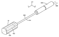
도 32a는 일 실시예에 따른 접근 조립체의 사시도로서, 이 접근 조립체는 접근 부재 및 개방부 생성 부재를 포함함.
<도 32b>
도 32b는 도 32a에 도시된 접근 부재의 측단면도.
<도 32c>
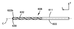
도 32c는 도 32a에 도시된 송곳의 측면도.
<도 32d>
도 32d는 대안적인 실시예에 따른, 도 32c에 도시된 송곳의 일부분의 측면도.
<도 32e>
도 32e는 목표 해부학적 위치 내로 삽입된 접근 조립체의 사시도.
<도 32f>
도 32f는 목표 해부학적 위치 내로 삽입된 접근 부재의 사시도.
<도 32g>
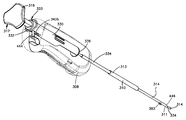
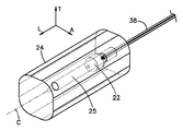
도 32g는 일 실시예에 따른 앵커 삽입기 조립체의 사시도로서, 이 앵커 삽입기 조립체는 접근 부재, 앵커를 지지하는 앵커 하우징, 및 푸셔 부재를 포함함.
<도 32h>
도 32h는 도 32g에 도시된 앵커 하우징의 측단면도.
<도 32i>
도 32i는 앵커가 아직 접근 부재로부터 방출되지 않은, 도 32g에 도시된 앵커 삽입기 조립체의 측단면도.
<도 32j>
도 32j는 도 32g에 도시된 푸셔 부재의 측단면도.
<도 32k>
도 32k는 앵커가 접근 부재로부터 방출되도록 푸셔 부재가 전진된, 도 32g에 도시된 앵커 삽입기 조립체의 측단면도.
<도 32l>
도 32l은 목표 해부학적 위치에서 확장된 앵커의 사시도.
<도 32m>
도 32m은 대안적인 실시예에 따라 구성된 앵커 조립체의 측단면도.
<도 33a>
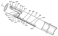
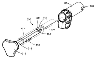
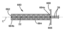
도 33a는 대안적인 실시예에 따른 앵커 삽입기 조립체의 사시도로서, 상기 앵커 삽입기 조립체는 접근 부재, 앵커를 지지하는 앵커 하우징, 및 인장 조립체를 포함함.
<도 33b>
도 33b는 도 33a에 도시된 인장 조립체의 구성요소의 측면도.
<도 33c>
도 33c는 인장 조립체가 앵커를 확장시키도록 작동되기 전의, 도 33a에 도시된 인장 조립체의 구성요소를 도시하는 사시도.
<도 33d>
도 33d는 인장 조립체가 앵커를 확장시키도록 작동된 후의, 도 33a에 도시된 인장 조립체의 구성요소를 도시하는 사시도.
<도 34a>
도 34a는 또 다른 대안적인 실시예에 따른 앵커 삽입기 조립체의 사시도로서, 이 앵커 삽입기 조립체는 접근 부재, 앵커를 지지하는 앵커 하우징, 및 인장 조립체를 포함함.
<도 34b>
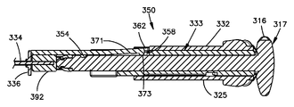
도 34b는 인장 조립체의 구성요소의 측단면도.
<도 34c>
도 34c는 인장 조립체가 앵커를 확장시키도록 작동되기 전의, 도 34a에 도시된 인장 조립체의 구성요소를 도시하는 부분 절단 사시도.
<도 34d>
도 34d는 인장 조립체가 앵커를 확장시키도록 작동된 후의, 도 34a에 도시된 인장 조립체의 구성요소를 도시하는 부분 절단 사시도.
<도 35a>
도 35a는 또 다른 대안적인 실시예에 따른 접근 부재의 분해 사시도로서, 앵커 삽입기 조립체는 송곳 및 접근 부재를 포함함.
<도 35b>
도 35b는 도 35a에 도시된 대안적인 실시예에 따른 앵커 삽입기 조립체의 분해 사시도로서, 이 앵커 삽입기 조립체는 접근 부재, 앵커를 지지하는 앵커 하우징, 및 인장 조립체를 포함함.
<도 36a>
도 36a는 도 35에 도시된 접근 부재 및 송곳을 포함하는 접근 조립체의 사시도.
<도 36b>
도 36b는 도 36a에 도시된 접근 조립체의 측단면도.
<도 37a>
도 37a는 접근 부재, 앵커를 지지하는 앵커 하우징, 및 도 35에 도시된 인장 조립체를 포함하는 앵커 삽입기 조립체의 사시도로서, 이 앵커 삽입기 조립체는 제1 작동 모드로 작동하도록 구성됨.
<도 37b>
도 37b는 도 37a에 도시된 앵커 삽입기 조립체의 절단 사시도.
<도 38>
도 38은 병진 부재가 중립 위치에 있는 상태에서 앵커 확장 모드로 작동하도록 구성된, 도 37a에 도시된 앵커 삽입기 조립체의 사시도.
<도 39>
도 39는 병진 부재가 연장된 위치에 있는, 도 38에 도시된 앵커 삽입기 조립체의 사시도.
<도 40a>
도 40a는 대안적인 실시예에 따라 구성된 병진 부재의 사시도.
<도 40b>
도 40b는 다른 대안적인 실시예에 따라 구성된 병진 부재의 정면도.
<도 41a>
도 41a는 다른 대안적인 실시예에 따라 구성된 병진 부재의 사시도.
<도 41b>
도 41b는 도 41a에 도시된 병진 부재의 정면도.
<도 42>
도 42는 다른 대안적인 실시예에 따라 구성된 병진 부재의 단면도.
<도 43>
도 43은 다른 대안적인 실시예에 따라 구성된 병진 부재의 단면도.
<도 44a 내지 도 44c>
도 44a 내지 도 44c는 작동 부재를 병진 부재에 고정시키도록 구성된 클리트(cleat)의 다양한 도면.
<도 45>
도 45는 한 쌍의 앵커 몸체를 각자의 목표 위치에 삽입하고 확장시키도록 구성된, 다른 실시예에 따라 구성된 삽입 기구의 사시도로서, 이 삽입 기구는 제1 몸체 및 제2 몸체를 차례로 포함하는 하우징을 포함함.
<도 46>
도 46은 푸셔 부재 및 개방부 생성 부재를 포함하는 제1 몸체의 분해 사시도.
<도 47a>
도 47a는 후퇴된 구성으로 도시된, 도 46에 도시된 제1 몸체의 사시도.
<도 47b>
도 47b는 제1 위치의 액추에이터를 도시하는, 도 47a에 도시된 제1 몸체의 액추에이터의 사시도.
<도 47c>
도 47c는 도 47a에 도시된 제1 몸체의 원위 단부의 사시도.
<도 48a>
도 48a는 연장된 구성으로 도시된, 도 46에 도시된 제1 몸체의 사시도.
<도 48b>
도 48b는 제2 위치의 액추에이터를 도시하는, 도 48a에 도시된 제1 몸체의 액추에이터의 사시도.
<도 48c>
도 48c는 도 48a에 도시된 제1 몸체의 원위 단부의 사시도.
<도 49a>
도 49a는 일 실시예에 따라 구성된 앵커 카트리지의 사시도.
<도 49b>
도 49b는 앵커 카트리지에 의해 지지되는 한 쌍의 앵커를 도시하기 위해 일부분이 감춰진, 도 49a에 도시된 앵커 카트리지의 다른 사시도.
<도 50a>
도 50a는 도 45에 도시된 삽입 기구의 일부분의 평면도로서, 초기 위치에 있는 도 49b에 도시된 앵커 카트리지 및 앵커 카트리지를 통해 연장된 개방부 생성 부재를 도시함.
<도 50b>
도 50b는 도 50a에 도시된 삽입 기구의 일부분의 평면도이지만, 후퇴된 개방부 생성 부재를 도시함.
<도 50c>
도 50c는 도 50b에 도시된 삽입 기구의 일부분의 평면도이지만, 제1 위치에 배치된 앵커 카트리지를 도시함.
<도 50d>
도 50d는 도 50c에 도시된 삽입 기구의 일부분의 평면도이지만, 앵커 카트리지를 통해 연장된 푸셔 부재를 도시함.
<도 50e>
도 50e는 도 50d에 도시된 삽입 기구의 일부분의 평면도이지만, 후퇴된 푸셔 부재를 도시함.
<도 50f>
도 50f는 도 50e에 도시된 삽입 기구의 일부분의 평면도이지만, 정지 클립(stop clip)이 제거된 것을 도시함.
<도 50g>
도 50g는 도 50f에 도시된 삽입 기구의 일부분의 평면도이지만, 제2 위치의 앵커 카트리지를 도시함.
<도 50h>
도 50h는 도 50g에 도시된 삽입 기구의 일부분의 평면도이지만, 앵커 카트리지를 통해 연장된 푸셔 부재를 도시함.
<도 51a>
도 51a는 도 45에 도시된 삽입 기구의 인장 조립체의 분해 사시도.
<도 51b>
도 51b는 제1 위치로 도시된, 도 51a에 도시된 인장 조립체의 측단면도.
<도 51c>
도 51c는 선 51C에서 취해진, 도 51b에 도시된 인장 조립체의 분해 측단면도.
<도 51d>
도 51d는 도 51B에 도시된 바와 같은 인장 조립체의 단부 단면도.
<도 51e>
도 51e는 제2 위치로 도시된, 도 51a에 도시된 인장 조립체의 측단면도.
<도 51f>
도 51f는 선 51F에서 취해진, 도 51e에 도시된 인장 조립체의 분해 측단면도.
<도 51g>
도 51g는 제3 위치로 도시된, 도 51a에 도시된 인장 조립체의 측단면도.
<도 51h>
도 51h는 선 51H에서 취해진, 도 51g에 도시된 인장 조립체의 분해 측단면도.
<도 51i>
도 51i는 도 51g에 도시된 바와 같은 인장 조립체의 단부 단면도.
<도 52a>
도 52a는 제1 목표 위치 내로 삽입되도록 구성된, 도 45에 도시된 삽입 기구의 사시도.
<도 52b>
도 52b는 제1 개방부를 생성하기 위해 제1 목표 위치 내로 삽입되어 도시된, 도 52a에 도시된 삽입 기구의 사시도.
<도 52c>
도 52c는 도 52b에 도시된 삽입 기구의 사시도이지만, 후퇴된 개방부 팁(tip)을 도시함.
<도 52d>
도 52d는 도 52c에 도시된 삽입 기구의 사시도이지만, 후퇴된 푸셔 부재를 도시함.
<도 53a>
도 53a는 도 52d에 도시된 삽입 기구의 사시도이지만, 제1 위치의 앵커 카트리지를 도시함.
<도 53b>
도 53b는 도 53a에 도시된 삽입 기구의 사시도이지만, 제1 개방부 내로 삽입된 제1 앵커 몸체를 도시함.
<도 53c>
도 53c는 도 53b에 도시된 삽입 기구의 사시도이지만, 삽입된 앵커 몸체를 확장시키도록 작동된 인장 조립체를 도시함.
<도 53d>
도 53d는 도 53c에 도시된 삽입 기구의 사시도이지만, 제1 위치의 인장 조립체를 도시함.
<도 53e>
도 53e는 제1 목표 위치로부터 제거되어 도시된, 도 53d에 도시된 삽입 기구의 사시도.
<도 54a>
도 54a는 제2 목표 위치 내로 삽입되도록 구성된, 도 53e에 도시된 삽입 기구의 사시도.
<도 54b>
도 54b는 제2 개방부를 생성하기 위해 제2 목표 위치 내로 삽입되어 도시된, 도 54a에 도시된 삽입 기구의 사시도.
<도 54c>
도 54c는 도 54b에 도시된 삽입 기구의 사시도이지만, 후퇴된 개방부 팁을 도시함.
<도 54d>
도 54d는 도 54c에 도시된 삽입 기구의 사시도이지만, 후퇴된 푸셔 부재를 도시함.
<도 55a>
도 55a는 도 54d에 도시된 삽입 기구의 사시도이지만, 정지 클립이 앵커 카트리지로부터 제거된 것을 도시함.
<도 55b>
도 55b는 도 55a에 도시된 삽입 기구의 사시도이지만, 제2 위치의 앵커 카트리지를 도시함.
<도 55c>
도 55c는 도 55b에 도시된 삽입 기구의 사시도이지만, 제2 개방부 내로 삽입된 제2 앵커 몸체를 도시함.
<도 55d>
도 55d는 도 55c에 도시된 삽입 기구의 사시도이지만, 삽입된 제2 앵커 몸체를 확장시키도록 작동된 인장 조립체를 도시함.
<도 55e>
도 55e는 도 55d에 도시된 삽입 기구의 사시도이지만, 제1 위치의 인장 조립체를 도시함.
<도 55f>
도 55f는 제2 목표 위치로부터 제거되어 도시된, 도 55e에 도시된 삽입 기구의 사시도.
<도 56a>
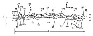
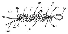
도 56a는 다른 실시예에 따라 구성된 확장가능한 앵커의 측면도로서, 이 확장가능한 앵커는 앵커 몸체 및 작동 스트랜드를 가지며, 제1 구성의 앵커 몸체를 도시함.
<도 56b>
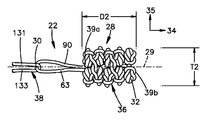
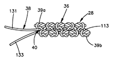
도 56b는 확장된 구성의 앵커 몸체를 도시하는, 도 56a에 도시된 확장가능한 앵커의 측면도.
<도 57a>
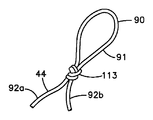
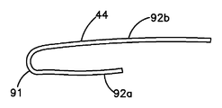
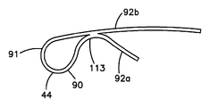
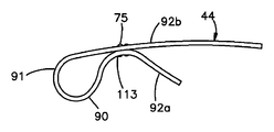
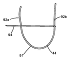
도 57a는 아일릿(eyelet)의 구성을 도시하는, 도 56a에 도시된 앵커 몸체를 생성하기 위한 제1 방법 단계의 측면도.
<도 57b 및 도 57c>
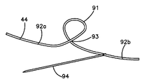
도 57b 및 도 57c는 일 실시예에 따른 도 57a에 도시된 아일릿을 생성하기 위한 방법 단계를 도시하는 도면.
<도 57d>
도 57d는 일 실시예에 따른 도 57a에 도시된 아일릿을 생성하기 위한 방법 단계를 도시하는 도면.
<도 57e>
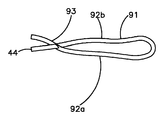
도 57e는 일 실시예에 따른 도 57a에 도시된 아일릿을 생성하기 위한 방법 단계를 도시하는 도면.
<도 57f 내지 도 57l>
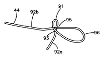
도 57f 내지 도 57l은 일 실시예에 따른 도 57a에 도시된 아일릿을 생성하기 위한 방법 단계를 도시하는 도면.
<도 58a>
도 58a는 도 56a에 도시된 앵커 몸체를 생성하기 위한 제2 방법 단계의 사시도로서, 도 57a에 도시된 아일릿을 맨드릴(mandrel) 주위로 결속하는 제1 매듭을 도시함.
<도 58b>
도 58b는 도 58a에 도시된 제2 방법 단계의 다른 사시도.
<도 58c>
도 58c는 도 56a에 도시된 앵커 몸체를 생성하기 위한 제3 방법 단계의 사시도로서, 제1 매듭에 대향되는 제2 매듭을 도시함.
<도 58d>
도 58d는 도 58d에 도시된 제3 방법 단계의 다른 사시도.
<도 58e>
도 58e는 도 56a에 도시된 앵커 몸체를 생성하기 위한 방법 단계의 사시도로서, 서로 대향되어 교대로 결속된 복수의 매듭을 도시함.
<도 58f>
도 58f는 도 58e에 도시된 방법 단계의 다른 사시도.
<도 58g>
도 58g는 맨드릴 주위에 배치된, 도 56a에 도시된 앵커 몸체의 사시도.
<도 58h>
도 58h는 도 58g에 도시된 앵커 몸체의 사시도로서, 아일릿을 통해 그리고 맨드릴을 통해 삽입된 작동 스트랜드를 도시함.
<도 58i>
도 58i는 도 58h에 도시된 작동 스트랜드 및 앵커 몸체의 사시도로서, 앵커 몸체를 통해 도입된 작동 스트랜드를 도시함.
<도 58j>
도 58j는 도 58i에 도시된 작동 스트랜드 및 앵커 몸체의 사시도로서, 앵커 몸체를 통해 도입된 아일릿을 도시함.
<도 59>
도 59는 도 56a에 도시된 확장가능한 앵커와 유사한 확장가능한 앵커의 사시도이지만, 아일릿을 앵커 몸체의 확장가능한 부분 내로 끌어당기기 전에 도시된, 외벌 매듭(overhand knot)으로서 구성된 앵커 몸체의 매듭을 도시함.
<도 60a>
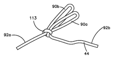
도 60a는 도 56a에 도시된 바와 같은 확장가능한 앵커와 유사한 확장가능한 앵커의 사시도이지만, 아일릿을 앵커 몸체의 확장가능한 부분 내로 끌어당기기 전의 한 쌍의 아일릿을 포함하는 앵커 몸체를 도시함.
<도 60b>
도 60b는 도 60a에 도시된 확장가능한 앵커의 사시도로서, 확장된 구성의 앵커 몸체를 도시함.
The following detailed description of the exemplary embodiments of the present application, as well as the foregoing, will be more clearly understood when read in conjunction with the accompanying drawings, in which exemplary embodiments are shown in the drawings for purposes of illustration. However, it should be understood that the present application is not limited to the precise arrangements and instrumentalities shown.
&Lt; RTI ID =
1A is a schematic side view of an anchor assembly including a pair of anchor bodies implanted across an anatomical defect and shown in a first configuration;
&Lt; RTI ID = 0.0 &
FIG. 1B is a schematic side view of the anchor assembly shown in FIG. 1A, showing the anchor body in an extended configuration and in an approached position. FIG.
1 (c)
FIG. 1C is a side view of the anchor assembly including a connector member configured to attach the anchor body shown in FIG. 1A and the operating portion of the anchor body, showing the anchor body in a first configuration; FIG.
Fig.
FIG. 1D is a side view of the anchor assembly shown in FIG. 1C showing the connector member tightened with the anchor body in an expanded configuration. FIG.
<Fig. 1E>
1E is a side view of the anchor assembly similar to FIG. 1C but including an integral connector member.
<1f>
FIG. 1F is a side view of the anchor assembly shown in FIG. 1E showing the connector member tightened with the anchor body in an expanded configuration. FIG.
Fig.
1G is a schematic side view of an anchor assembly including a pair of anchor bodies constructed in accordance with an alternative embodiment, shown implanted across an anatomical defect and shown in a first configuration;
&Lt; RTI ID =
1H is a schematic side view of the anchor assembly shown in FIG. 1G showing the anchor body in an extended configuration and in an approached position.
&Lt;
2A is a side view of an anchor assembly including first and second anchors implanted in an anatomical structure on opposite sides of the anatomical defect and shown in a first configuration;
2b,
FIG. 2B is a side view of the anchor assembly shown in FIG. 2A, showing the first and second anchors in their respective extended configurations. FIG.
Fig.
FIG. 2C is a side view of the anchor assembly shown in FIG. 2A, including a connector member attaching the first anchor to the second anchor. FIG.
3A,
3A is a side view of a fixation kit including at least one anchor and insertion mechanism.
3b,
3B is a side cross-sectional view of the fixation kit shown in FIG. 3A.
4A,
4A is a cross-sectional view of a fixing kit constructed in accordance with an alternative embodiment, shown in a first rotational state.
4 (b)
4B is a side cross-sectional view of the kit shown in FIG. 4A, taken along lines 4B-4B.
4C,
4C is a cross-sectional side view of the fixation kit as shown in FIG. 4A but shown in a second rotational state with a pair of openings aligned;
4D,
4D is a cross-sectional side view of the fixation kit shown in FIG. 4C taken along lines 4D-4D.
5A)
5A is a side cross-sectional view of the insertion mechanism during assembly.
5B,
FIG. 5B is a side cross-sectional view of the insertion instrument shown in FIG. 5A, but assembled.
5C)
5C is a side cross-sectional view of the handle of the insertion instrument shown in FIG. 5B.
5D)
5D is a perspective view of the handle shown in FIG. 5C.
6,
6 is a side view of a fixation kit constructed in accordance with another embodiment.
7a)
FIG. 7A is a perspective view of a fixation kit including an insertion instrument constructed in accordance with an alternative embodiment including a casing and a cannula extending from the casing, the instrument having a first and second anchor body loaded into the insertion instrument; FIG. Shown in the first configuration.
7B,
FIG. 7B is an enlarged perspective view of the cannula of the insertion instrument shown in FIG. 7A.
7C,
FIG. 7C is a side cross-sectional view of the casing of the insertion instrument shown in FIG. 7A. FIG.
7D,
FIG. 7D is an enlarged side cross-sectional view of the cannula of the insertion instrument shown in FIG. 7A.
8A,
FIG. 8A is a perspective view of the fixing kit shown in FIG. 7A showing the insertion mechanism in a second position for releasing the second anchor body from the insertion mechanism, wherein the second anchor body is shown in a first configuration. FIG.
Figure 8b
FIG. 8B is an enlarged perspective view of the cannula of the insertion instrument shown in FIG. 8A.
Figure 8c
8C is a side cross-sectional view of the casing shown in FIG. 8A.
Fig.
8D is a side cross-sectional view of the cannula shown in FIG. 8A.
9A,
FIG. 9A is a perspective view of the fixation kit shown in FIG. 8A showing the insertion mechanism in an offset position. FIG.
9B,
9B is an enlarged perspective view of the cannula of the insertion instrument shown in FIG. 9A.
9C)
9C is a side cross-sectional view of the casing of the insertion instrument shown in FIG. 9A.
9D,
9D is a side cross-sectional view of the cannula of the insertion instrument shown in FIG. 9A.
9E)
9E is a perspective view of the fixing kit shown in FIG. 9A, showing a second anchor body in an expanded configuration.
Figure 10a
10A is a perspective view of the fixation kit shown in FIG. 9A showing the insertion mechanism in the intermediate position upon completion of the intermediate stroke.
Figure 10b
10B is an enlarged perspective view of the cannula of the insertion instrument shown in FIG. 10A.
<Fig. 10c>
10C is a side cross-sectional view of the casing of the insertion instrument shown in FIG. 10A.
10D,
10D is a side cross-sectional view of the cannula of the insertion instrument shown in FIG. 10A.
<FIG. 11A>
FIG. 11A is a perspective view of the fastening kit shown in FIG. 10A showing the insertion mechanism upon completion of the first portion of the second stroke after the intermediate stroke. FIG.
Figure 11b
FIG. 11B is an enlarged perspective view of the cannula of the insertion instrument shown in FIG. 11A.
11 (c)
FIG. 11C is a side cross-sectional view of the casing of the insertion instrument shown in FIG. 11A. FIG.
11 (d)
FIG. 11D is a side cross-sectional view of the cannula of the insertion instrument shown in FIG. 11A. FIG.
12A,
FIG. 12A is a perspective view of the fixing kit shown in FIG. 11A showing the insertion mechanism in a third position upon completion of the second portion of the second stroke, releasing the first anchor body from the insertion mechanism, wherein the first anchor body is Shown in the first configuration.
12B,
12B is an enlarged perspective view of the cannula of the insertion instrument shown in FIG. 12A.
12C,
12C is a side cross-sectional view of the casing of the insertion instrument shown in FIG. 12A.
12D,
12D is a side cross-sectional view of the cannula of the insertion instrument shown in FIG. 12A.
12E)
FIG. 12E is a perspective view of a fixing kit similar to FIG. 12A, but showing the first anchor body in an expanded configuration. FIG.
Figure 12f
12F is a side cross-sectional view of the casing of the insertion mechanism shown in FIG. 12A after release of the strand retaining mechanism.
Figure 13a
13A is a perspective view of the insertion instrument shown in FIG. 7A with portions removed to show the guide system when the instrument is in the first position.
Figure 13b
FIG. 13B is a perspective view of the insertion instrument shown in FIG. 8A showing the guide system when the instrument is in the second position; FIG.
13 (c)
13C is a perspective view of the insertion instrument shown in FIG. 9A with portions removed to show the guide system when the insertion instrument is in the offset position.
13D,
FIG. 13D is a perspective view of the insertion instrument shown in FIG. 10A with portions removed to show the guide system when the insertion instrument is in an intermediate position; FIG.
13E)
FIG. 13E is a perspective view of the insertion instrument shown in FIG. 11A with portions removed to show the guide system when the insertion instrument has completed the first portion of the second stroke. FIG.
Figure 13f
FIG. 13F is a perspective view of the insertion instrument shown in FIG. 12A with portions removed to show the guide system when the insertion instrument has completed the second portion of the second stroke. FIG.
Figure 13g
13G is a perspective view of the guide track of the guide system shown in FIG. 13A.
14A and 14B,
14A is a perspective view of a coupling assembly configured according to one embodiment.
14B,
FIG. 14B is a side cross-sectional view of the coupling assembly shown in FIG. 14A, shown in a first mode of operation. FIG.
14C)
FIG. 14C is a side cross-sectional view of the coupling assembly shown in FIG. 14B, shown in a transition state between the first mode of operation and the second mode of operation. FIG.
Figure 14d
FIG. 14D is a side cross-sectional view of the coupling assembly shown in FIG. 14C, shown in a second mode of operation. FIG.
15A,
15A is a side cross-sectional view of an insertion instrument constructed in accordance with another embodiment, showing a coupling assembly disposed in a first mode of operation;
15B,
15B is an end cross-sectional view of the coupling assembly shown in FIG. 15A, taken along line 15B-15B.
15C)
FIG. 15C is a side cross-sectional view of the insertion instrument shown in FIG. 15A, but showing the coupling assembly transitioning from the first mode of operation to the second mode of operation. FIG.
15D,
15D is an end cross-sectional view of the coupling assembly shown in FIG. 15C taken along line 15D-15D.
15E)
FIG. 15E is a side cross-sectional view of the insertion instrument shown in FIG. 15C, but showing the coupling assembly in a second mode of operation. FIG.
16A,
FIG. 16A is a schematic side view of an anchor assembly as shown in FIG. 1G, including a tension strand according to an alternative embodiment, showing one of the anchor bodies implanted in a first configuration. FIG.
16B,
FIG. 16B is a schematic side view of the anchor assembly as shown in FIG. 16A, but showing the implanted anchor body in an expanded configuration. FIG.
16 (c)
FIG. 16C is a schematic side view of the anchor assembly as shown in FIG. 16B, showing another anchor body implanted in a first configuration. FIG.
16D,
FIG. 16D is a schematic side view of the anchor assembly as shown in FIG. 16C, showing another anchor body in an expanded configuration. FIG.
16E)
FIG. 16E is a schematic side view of an anchor assembly as shown in FIG. 16D, showing locking of a locking member. FIG.
Figure 16f
FIG. 16F is a schematic side view of the anchor assembly as shown in FIG. 16E, shown in a final assembled configuration. FIG.
17A,
17A is a perspective view of a strand retaining assembly constructed in accordance with one embodiment, showing a releasable locking member.
17B,
FIG. 17B is a perspective view of the strand retaining assembly shown in FIG. 17A, showing a locked locking member. FIG.
17 (c)
FIG. 17C is a perspective view of the strand retaining assembly shown in FIG. 17A, operably coupled to the actuator. FIG.
17D,
FIG. 17D is a perspective view of the strand retaining assembly shown in FIG. 17C, shown in the released position. FIG.
18A,
18A is a schematic side view of an anchor assembly as shown in FIG. 1G, including a pair of tension strands according to an alternative embodiment, showing the anchor body in a first configuration.
18B,
FIG. 18B is a schematic side view of the anchor assembly as shown in FIG. 18A, but showing the anchor body in an expanded configuration. FIG.
18C,
FIG. 18C is a schematic side view of the anchor assembly as shown in FIG. 18B, illustrating the operation of the locking member and access to the anatomical gap. FIG.
18D,
FIG. 18D is a schematic side view of the anchor assembly as shown in FIG. 18C showing the locking of the locking member. FIG.
Figure 18e
18E is a schematic side view of the anchor assembly as shown in FIG. 18D, shown in a final assembled configuration.
19A)
19A is a schematic side cross-sectional view of a retaining assembly of an insertion instrument constructed in accordance with another embodiment, shown in a locked configuration;
19B,
19B is a schematic side cross-sectional view of the retaining assembly of the insertion instrument shown in FIG. 19A, shown in an unlocked configuration.
19 (c)
19C is a side cross-sectional view of the casing of the insertion instrument similar to the insertion instrument as shown in FIG. 12C but including a retaining assembly constructed in accordance with an alternative embodiment.
20A,
20A is a side cross-sectional view of an insertion instrument that includes a cutting assembly according to another embodiment, showing the cutting assembly in the disengaged position.
20B,
FIG. 20B is a side cross-sectional view of the insertion instrument as shown in FIG. 20A, but showing the cutting assembly in the engaged position. FIG.
21A,
FIG. 21A is a side cross-sectional view of an insertion instrument that includes a cutting assembly configured according to another embodiment, as shown in FIG. 20A, but shown in a disengaged position.
21 (b)
FIG. 21B is a side cross-sectional view of the insertion instrument as shown in FIG. 21A, but showing the cutting assembly in the engaged position. FIG.
22A,
FIG. 22A is a perspective view of an insertion instrument constructed in accordance with an alternative embodiment, shown in FIG. 7A but shown in a first position; FIG.
22B,
FIG. 22B is a side view of the insertion instrument as shown in FIG. 22A.
22C,
FIG. 22C is a side view of the insertion instrument shown in FIG. 22B but shown in a second position; FIG.
22D,
FIG. 22D is a side view of the insertion instrument shown in FIG. 22C but shown in a third position. FIG.
23A)
FIG. 23A is a perspective view of the insertion instrument constructed similar to the insertion instrument shown in FIG. 7A, but constructed in accordance with another embodiment, and shown in a first position. FIG.
23B,
FIG. 23B is a perspective view of the plunger of the insertion instrument shown in FIG. 23A. FIG.
23C,
FIG. 23C is a perspective view of the distal end of the insertion instrument shown in FIG. 23A. FIG.
23D,
FIG. 23D is a perspective view of various components of the insertion mechanism shown in FIG. 23A, including the plunger, push rod, and a pair of first coupling members shown in FIG. 23B.
23E)
FIG. 23E is a perspective view of a second coupling member configured to engage with the first coupling member shown in FIG. 23D. FIG.
23F,
FIG. 23F is a perspective view of the insertion mechanism shown in FIG. 23A, shown in a second position. FIG.
Figure 23g
FIG. 23G is a perspective view of the insertion instrument shown in FIG. 23F, shown in an intermediate position. FIG.
Figure 23h
FIG. 23H is a perspective view of the insertion instrument shown in FIG. 23G, shown in a third position; FIG.
24A)
FIG. 24A is a perspective view of an insertion instrument including first and second pusher assemblies disposed in parallel relationship, each showing a pusher assembly in a first position; FIG.
24B,
FIG. 24B is a perspective view of the insertion mechanism shown in FIG. 24A after removal of the first lockout tab from the first pusher assembly. FIG.
24C,
24C is a perspective view of the insertion mechanism shown in FIG. 24B after operation of the first pusher assembly to the second position.
24D)
FIG. 24D is a perspective view of the insertion mechanism shown in FIG. 24C after removal of the second lockout tab from the second pusher assembly. FIG.
24E)
FIG. 24E is a perspective view of the insertion mechanism shown in FIG. 24D after operation of a swap actuator. FIG.
24F]
24F is a perspective view of the insertion mechanism shown in FIG. 24E after operation of the second pusher assembly to the second position.
25A)
FIG. 25A is a perspective view of the components of the insertion instrument shown in FIG. 24A, showing each of the first and second pusher assemblies in a first position. FIG.
25B,
FIG. 25B is a perspective view of the components of the insertion instrument shown in FIG. 25A after the first pusher assembly has been operated in the second position.
25C)
FIG. 25C is a perspective view of the components of the insertion mechanism shown in FIG. 25B after operation of the swap actuator. FIG.
25D,
FIG. 25D is a perspective view of the components of the insertion instrument shown in FIG. 25C after the second pusher assembly has been operated in the second position.
26A and 26B,
26A is a perspective view of a retention assembly constructed in accordance with one embodiment.
26b,
FIG. 26B is an enlarged perspective view of a portion of the retaining assembly shown in FIG. 26A.
&Lt;
27A is a perspective view of an insertion instrument constructed in accordance with another embodiment, showing each of the pusher assemblies in a first position, including first and second pusher assemblies disposed in parallel relationship;
27B,
FIG. 27B is a perspective view of the insertion mechanism shown in FIG. 27A after operation of the first pusher assembly in a position configuration. FIG.
27C,
FIG. 27C is a perspective view of the components of the insertion mechanism shown in FIG. 27B after operation of the swap actuator from the first position to the operated position. FIG.
Figure 27d
FIG. 27D is a perspective view of the insertion mechanism shown in FIG. 27C after operation of the second pusher assembly to the second position. FIG.
28A,
FIG. 28A is a perspective view of the components of the insertion mechanism shown in FIG. 27A, shown with the swap actuator in the first position; FIG.
28B,
FIG. 28B is a perspective view of the components of the insertion instrument shown in FIG. 28A, shown with the swap actuator in the second position; FIG.
29A,
29A is a perspective view of an insertion instrument constructed in accordance with another embodiment, showing each of the pusher assemblies in a first position, including first and second pusher assemblies disposed in parallel relationship;
29b,
29B is an end view of the insertion instrument shown in FIG. 29A.
Figure 29c
FIG. 29C is a perspective view of the insertion mechanism shown in FIG. 29A, showing the first pusher assembly in a second position. FIG.
<FIG. 29D>
FIG. 29D is a perspective view of the insertion mechanism shown in FIG. 29C after operation of the swap actuator from the first position to the second position. FIG.
<FIG. 29E>
FIG. 29E is a perspective view of the insertion mechanism shown in FIG. 29D after removal of the lockout tab from the second pusher assembly. FIG.
Figure 29f
FIG. 29F is a perspective view of the insertion mechanism shown in FIG. 29E showing the second pusher assembly in the second position; FIG.
<Fig. 29G>
FIG. 29G is a schematic end cross-sectional view of the insertion mechanism shown in FIG. 29D showing a portion of a swap actuator. FIG.
30A)
30A is a perspective view of an insertion instrument constructed in accordance with another embodiment, the first and second cannulas being movable in opposition, the figure being cut away to expose the internal components of the insertion instrument; Shows part of the casing.
30 (b)
FIG. 30B is a perspective view of the upper motion assembly of the insertion instrument shown in FIG. 30A, the upper motion assembly configured to drive the first and second cannulas oppositely.
30C)
30C is a perspective view of the drive member of the upper half movement assembly shown in FIG. 30B.
Figure 30d
30D illustrates a perspective view of an optional plunger engagement assembly configured to selectively move a plunger between an operably connected first and second cannula.
31,
31 is a perspective view of the insertion instrument, wherein the cannula defines a side release port according to another embodiment.
32A)
32A is a perspective view of an access assembly according to one embodiment, the access assembly including an access member and an opening generating member.
32B,
32B is a side cross-sectional view of the access member shown in FIG. 32A.
<FIG. 32C>
FIG. 32C is a side view of the awl shown in FIG. 32A. FIG.
<FIG. 32D>
FIG. 32D is a side view of a portion of the awl shown in FIG. 32C, according to an alternative embodiment. FIG.
<FIG. 32E>
32E illustrates a perspective view of an access assembly inserted into a target anatomical position.
Figure 32f
32F is a perspective view of an access member inserted into a target anatomical position.
<Fig. 32g>
32G is a perspective view of an anchor inserter assembly according to one embodiment, the anchor inserter assembly including an access member, an anchor housing that supports the anchor, and a pusher member.
<FIG. 32H>
32H is a side cross-sectional view of the anchor housing shown in FIG. 32G.
<FIG. 32i>
FIG. 32I is a side cross-sectional view of the anchor inserter assembly shown in FIG. 32G with the anchor not yet released from the access member. FIG.
<FIG. 32j>
32J is a side cross-sectional view of the pusher member shown in FIG. 32G.
<FIG. 32K>
FIG. 32K is a side cross-sectional view of the anchor inserter assembly shown in FIG. 32G with the pusher member advanced such that the anchor is released from the access member. FIG.
Figure 32L
32L is a perspective view of the anchor extended in the target anatomical position.
<FIG. 32 m>
32M is a side cross-sectional view of an anchor assembly constructed in accordance with an alternative embodiment.
33A)
33A is a perspective view of an anchor inserter assembly in accordance with an alternative embodiment, wherein the anchor inserter assembly includes an access member, an anchor housing that supports the anchor, and a tension assembly.
Figure 33b
33B is a side view of the components of the tension assembly shown in FIG. 33A.
Figure 33c
FIG. 33C is a perspective view illustrating components of the tension assembly shown in FIG. 33A before the tension assembly is operated to expand the anchor. FIG.
Figure 33d
FIG. 33D is a perspective view illustrating components of the tension assembly shown in FIG. 33A after the tension assembly has been operated to expand the anchor. FIG.
34A,
34A is a perspective view of an anchor inserter assembly in accordance with yet another alternative embodiment, the anchor inserter assembly including an access member, an anchor housing that supports the anchor, and a tension assembly.
Figure 34b
34B is a side cross-sectional view of the components of a tension assembly.
34C,
FIG. 34C is a partial cutaway perspective view of the components of the tension assembly shown in FIG. 34A before the tension assembly is actuated to expand the anchor. FIG.
34D,
FIG. 34D is a partial cutaway perspective view of the components of the tension assembly shown in FIG. 34A after the tension assembly has been operated to expand the anchor. FIG.
<Fig. 35a>
35A is an exploded perspective view of an access member according to another alternative embodiment, wherein the anchor inserter assembly includes an auger and an access member.
35B,
FIG. 35B is an exploded perspective view of an anchor inserter assembly according to an alternative embodiment shown in FIG. 35A, wherein the anchor inserter assembly includes an access member, an anchor housing that supports the anchor, and a tension assembly.
<Figure 36a>
FIG. 36A is a perspective view of an access assembly including the access member and auger shown in FIG. 35. FIG.
<Figure 36b>
36B is a side cross-sectional view of the access assembly shown in FIG. 36A.
<Figure 37a>
FIG. 37A is a perspective view of an anchor inserter assembly including an access member, an anchor housing for supporting the anchor, and the tension assembly shown in FIG. 35, wherein the anchor inserter assembly is configured to operate in a first mode of operation. FIG.
Figure 37b
FIG. 37B is a cut away perspective view of the anchor inserter assembly shown in FIG. 37A. FIG.
38,
FIG. 38 is a perspective view of the anchor inserter assembly shown in FIG. 37A, configured to operate in anchor expansion mode with the translation member in a neutral position.
39,
FIG. 39 is a perspective view of the anchor inserter assembly shown in FIG. 38 with the translation member in an extended position. FIG.
<Fig. 40a>
40A is a perspective view of a translation member constructed in accordance with an alternative embodiment.
&Lt; 40b >
40B is a front view of a translation member constructed in accordance with another alternative embodiment.
41A,
41A is a perspective view of a translation member constructed in accordance with another alternative embodiment.
41b,
FIG. 41B is a front view of the translation member shown in FIG. 41A. FIG.
42,
42 is a cross-sectional view of a translation member constructed in accordance with another alternative embodiment.
<Fig. 43>
43 is a cross-sectional view of a translation member constructed in accordance with another alternative embodiment.
44A to 44C,
44A-44C show various views of cleats configured to secure the actuation member to the translational member.
<Fig. 45>
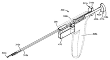
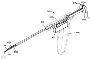
45 is a perspective view of an insertion instrument constructed in accordance with another embodiment, configured to insert and extend a pair of anchor bodies in their respective desired positions, the insertion mechanism including a housing, which in turn includes a first body and a second body; Included.
46,
46 is an exploded perspective view of the first body including the pusher member and the opening generating member.
<Figure 47a>
FIG. 47A is a perspective view of the first body shown in FIG. 46, shown in a retracted configuration; FIG.
<Figure 47b>
FIG. 47B is a perspective view of the actuator of the first body shown in FIG. 47A, showing the actuator in the first position; FIG.
Figure 47c
FIG. 47C is a perspective view of the distal end of the first body shown in FIG. 47A.
48a)
48A is a perspective view of the first body shown in FIG. 46, shown in an extended configuration;
48b)
FIG. 48B is a perspective view of the actuator of the first body shown in FIG. 48A, showing the actuator in the second position; FIG.
Figure 48c
48C is a perspective view of the distal end of the first body shown in FIG. 48A.
<Figure 49a>
49A is a perspective view of an anchor cartridge constructed in accordance with one embodiment.
<Figure 49b>
FIG. 49B is another perspective view of the anchor cartridge shown in FIG. 49A, partially hidden to illustrate a pair of anchors supported by the anchor cartridge. FIG.
50a)
50A is a plan view of a portion of the insertion mechanism shown in FIG. 45, showing the anchor cartridge shown in FIG. 49B in its initial position and the opening generating member extending through the anchor cartridge.
<Fig. 50b>
FIG. 50B is a plan view of a portion of the insertion instrument shown in FIG. 50A, but showing the retracted opening creating member. FIG.
Figure 50c
FIG. 50C is a plan view of a portion of the insertion instrument shown in FIG. 50B, but showing the anchor cartridge disposed in the first position; FIG.
<FIG. 50D>
FIG. 50D is a top view of a portion of the insertion mechanism shown in FIG. 50C, but showing the pusher member extending through the anchor cartridge. FIG.
<Figure 50e>
FIG. 50E is a top view of a portion of the insertion mechanism shown in FIG. 50D, but showing the retracted pusher member. FIG.
Figure 50f
FIG. 50F is a top view of a portion of the insertion instrument shown in FIG. 50E, but shows a stop clip removed. FIG.
<50g>
FIG. 50G is a top view of a portion of the insertion instrument shown in FIG. 50F, but showing the anchor cartridge in a second position. FIG.
<Figure 50h>
FIG. 50H is a top view of a portion of the insertion mechanism shown in FIG. 50G, but showing the pusher member extending through the anchor cartridge. FIG.
<51a>
51A is an exploded perspective view of the tension assembly of the insertion instrument shown in FIG. 45.
51B,
FIG. 51B is a side cross-sectional view of the tension assembly shown in FIG. 51A, shown in a first position.
Figure 51c
FIG. 51C is an exploded side cross-sectional view of the tension assembly shown in FIG. 51B taken at line 51C. FIG.
Fig. 51D
51D is an end cross-sectional view of the tension assembly as shown in FIG. 51B.
Figure 51e
FIG. 51E is a side cross-sectional view of the tension assembly shown in FIG. 51A, shown in a second position.
Figure 51f
FIG. 51F is an exploded side cross-sectional view of the tension assembly shown in FIG. 51E taken at line 51F.
<Figure 51g>
FIG. 51G is a side cross-sectional view of the tension assembly shown in FIG. 51A, shown in a third position. FIG.
<Figure 51h>
FIG. 51H is an exploded side cross-sectional view of the tension assembly shown in FIG. 51G, taken at line 51H.
Figure 51i
51I is an end cross-sectional view of the tension assembly as shown in FIG. 51G.
52A,
52A is a perspective view of the insertion instrument shown in FIG. 45, configured to be inserted into a first target position.
52B,
52B is a perspective view of the insertion mechanism shown in FIG. 52A, shown inserted into a first target position to create a first opening.
52C,
FIG. 52C is a perspective view of the insertion mechanism shown in FIG. 52B but showing the retracted opening tip. FIG.
52D,
FIG. 52D is a perspective view of the insertion mechanism shown in FIG. 52C but showing the retracted pusher member. FIG.
53A)
FIG. 53A is a perspective view of the insertion mechanism shown in FIG. 52D but showing the anchor cartridge in the first position; FIG.
Figure 53b
FIG. 53B is a perspective view of the insertion mechanism shown in FIG. 53A, but showing the first anchor body inserted into the first opening. FIG.
Figure 53c
FIG. 53C is a perspective view of the insertion mechanism shown in FIG. 53B, but showing a tension assembly operated to expand the inserted anchor body. FIG.
Figure 53d
FIG. 53D is a perspective view of the insertion instrument shown in FIG. 53C but showing the tension assembly in the first position; FIG.
53E)
53E is a perspective view of the insertion instrument shown in FIG. 53D, shown removed from the first target position.
<Figure 54a>
54A is a perspective view of the insertion mechanism shown in FIG. 53E, configured to be inserted into a second target position.
<Figure 54b>
54B is a perspective view of the insertion mechanism shown in FIG. 54A, shown inserted into a second target position to create a second opening.
<Figure 54c>
FIG. 54C is a perspective view of the insertion mechanism shown in FIG. 54B, but showing the retracted opening tip. FIG.
<Figure 54d>
FIG. 54D is a perspective view of the insertion mechanism shown in FIG. 54C but showing the retracted pusher member. FIG.
<Figure 55a>
FIG. 55A is a perspective view of the insertion mechanism shown in FIG. 54D, showing that the stop clip has been removed from the anchor cartridge. FIG.
<Figure 55b>
FIG. 55B is a perspective view of the insertion mechanism shown in FIG. 55A, but showing the anchor cartridge in a second position. FIG.
Fig. 55c
FIG. 55C is a perspective view of the insertion mechanism shown in FIG. 55B but showing a second anchor body inserted into the second opening. FIG.
<Figure 55d>
FIG. 55D is a perspective view of the insertion instrument shown in FIG. 55C but showing a tension assembly operated to expand the inserted second anchor body. FIG.
<Figure 55e>
FIG. 55E is a perspective view of the insertion mechanism shown in FIG. 55D, but showing the tension assembly in the first position. FIG.
<Figure 55f>
55F is a perspective view of the insertion mechanism shown in FIG. 55E, shown removed from the second target position.
<Figure 56a>
56A is a side view of an expandable anchor constructed in accordance with another embodiment, the expandable anchor having an anchor body and an actuation strand, illustrating the anchor body of the first configuration.
<Figure 56b>
56B is a side view of the expandable anchor shown in FIG. 56A, showing the anchor body in an expanded configuration.
<Figure 57a>
FIG. 57A is a side view of a first method step for creating the anchor body shown in FIG. 56A, showing the configuration of an eyelet; FIG.
57B and 57C
57B and 57C illustrate method steps for generating the eyelet shown in FIG. 57A according to one embodiment.
<Figure 57d>
FIG. 57D illustrates method steps for generating the eyelet shown in FIG. 57A, according to an embodiment. FIG.
<Figure 57e>
FIG. 57E illustrates method steps for generating the eyelet shown in FIG. 57A, according to an embodiment. FIG.
57F to 57L
57F through 57L illustrate method steps for generating the eyelet shown in FIG. 57A according to one embodiment.
58A,
FIG. 58A is a perspective view of a second method step for creating the anchor body shown in FIG. 56A, showing a first knot that binds the eyelet shown in FIG. 57A around a mandrel. FIG.
58b,
58B is another perspective view of the second method step shown in FIG. 58A.
58C,
FIG. 58C is a perspective view of a third method step for producing the anchor body shown in FIG. 56A, showing a second knot opposite the first knot; FIG.
Fig. 58D
FIG. 58D is another perspective view of the third method step shown in FIG. 58D. FIG.
<Figure 58e>
FIG. 58E is a perspective view of a method step for producing the anchor body shown in FIG. 56A, showing a plurality of knots opposed to and alternately bound together; FIG.
Fig. 58f
58F is another perspective view of the method step shown in FIG. 58E.
<Figure 58g>
FIG. 58G is a perspective view of the anchor body shown in FIG. 56A, disposed around the mandrel. FIG.
<Figure 58h>
FIG. 58H is a perspective view of the anchor body shown in FIG. 58G, showing the actuation strand inserted through the eyelet and through the mandrel. FIG.
<Figure 58i>
FIG. 58I is a perspective view of the actuation strand and anchor body shown in FIG. 58H, illustrating the actuation strand introduced through the anchor body. FIG.
<Figure 58j>
FIG. 58J is a perspective view of the actuation strand and anchor body shown in FIG. 58I, illustrating eyelets introduced through the anchor body. FIG.
<Fig. 59>
FIG. 59 is a perspective view of the expandable anchor similar to the expandable anchor shown in FIG. 56A, but showing the knot of the anchor body configured as an overhand knot, shown before pulling the eyelet into the expandable portion of the anchor body. .
<Figure 60a>
FIG. 60A is a perspective view of an expandable anchor similar to the expandable anchor as shown in FIG. 56A, but showing the anchor body including a pair of eyelets prior to pulling the eyelets into the expandable portion of the anchor body. FIG.
<Figure 60b>
FIG. 60B is a perspective view of the expandable anchor shown in FIG. 60A, showing the anchor body in an expanded configuration. FIG.

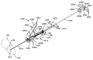
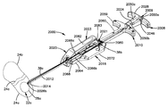
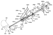
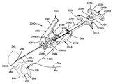
처음에 도 1a 및 도 1b를 참조하면, 앵커 조립체(20)는 적어도 하나의 해부학적 구조물(24)에 의해 한정될 수 있는 해부학적 위치에 고정되도록 구성된 각자의 앵커 몸체(28a, 28b)를 차례로 포함하는 제1 확장가능한 앵커(22a) 및 제2 확장가능한 앵커(22b)와 같은 적어도 하나의 확장가능한 앵커(22)를 포함할 수 있다. 해부학적 구조물(24)은 예를 들어 사람 또는 다른 동물의 해부학적 구조물, 또는 사람 또는 다른 동물의 해부학적 구조물에 고정되거나 고정되도록 구성된 임플란트에 의해 한정될 수 있다. 해부학적 구조물은 골 및 연조직, 예를 들어 건(tendon), 인대, 연골, 추간판의 섬유륜 등 중 적어도 하나를 포함할 수 있는 조직에 의해 한정될 수 있다.Referring initially to FIGS. 1A and 1B, the anchor assembly 20 in turn rotates its respective anchor bodies 28a, 28b configured to be secured in an anatomical position that may be defined by at least one anatomical structure 24. It may include at least one expandable anchor 22, such as including a first expandable anchor 22a and a second expandable anchor 22b. Anatomical structure 24 may be defined, for example, by an anatomical structure of a human or other animal, or an implant configured to be fixed or secured to an anatomical structure of a human or other animal. Anatomical structures may be defined by tissues that may include at least one of bone and soft tissue, such as tendons, ligaments, cartilage, annulus fibrosus, and the like.

일 실시예에 따르면, 적어도 하나의 해부학적 구조물(24)은 갭(24c)과 같은 갭의 대향 측들에 제1 및 제2 목표 해부학적 위치(24a, 24b)를 한정할 수 있다. 따라서, 갭(24c)은 해부학적 구조물 내에 배치될 수 있으며, 예를 들어 해부학적 결손부를 한정할 수 있거나, 여러 해부학적 구조물 사이에 배치될 수 있다. 제1 및 제2 앵커(22a, 22b)는 갭(24c)의 대향 측들에서 각자의 제1 및 제2 목표 해부학적 위치(24a, 24b) 내로 주입되거나 달리 도입 또는 삽입될 수 있고, 후속적으로 갭(24c)을 접근시키기 위해 서로를 향해 끌어당겨질 수 있다. 대안적으로 또는 더욱 부가적으로, 앵커 조립체(20)는 보조 구조물을 해부학적 구조물에 고정시키도록 구성될 수 있다. 이와 관련하여, 앵커 조립체(20)는 원하는 바에 따라 임의의 수의 앵커(22)를 포함할 수 있음을 또한 인식하여야 한다.According to one embodiment, at least one anatomical structure 24 may define first and second target anatomical positions 24a, 24b on opposite sides of the gap, such as gap 24c. Thus, gap 24c may be disposed within an anatomical structure, for example, may define an anatomical defect, or may be disposed between several anatomical structures. The first and second anchors 22a and 22b may be injected or otherwise introduced or inserted into their respective first and second target anatomical positions 24a and 24b on opposite sides of the gap 24c and subsequently It may be pulled towards each other to approach the gap 24c. Alternatively or additionally, anchor assembly 20 may be configured to secure the secondary structure to the anatomical structure. In this regard, it should also be appreciated that the anchor assembly 20 may include any number of anchors 22 as desired.

각각의 앵커 몸체(28a, 28b)는 각자의 확장가능한 부분(36a, 36b)과, 각자의 확장가능한 부분(36a, 36b), 및 이에 따라 각자의 앵커 몸체(28a, 28b)를 앵커 몸체(28a, 28b)가 초기에 목표 해부학적 위치에 배치되는 도 1a에 도시된 제1 구성으로부터, 각자의 앵커 몸체(28a, 28b)가 해부학적 구조물(24)에 고정될 수 있는 도 1b에 도시된 확장된 구성으로 작동시키도록 구성되는, 작동 스트랜드(38a, 38b)와 같은, 작동 부재(37a, 37b)를 포함할 수 있다. 따라서, 앵커(22a, 22b)의 앵커 몸체(28a, 28b)는 예를 들어 가령 앵커 몸체(28a, 28b)를 각자의 목표 해부학적 위치(24a, 24b)에 주입함으로써 앵커 몸체(28a, 28b)를 각자의 목표 해부학적 위치(24a, 24b)에 전달할 때 생성될 수 있는 각자의 목표 해부학적 위치(24a, 24b)의 개방부(23)를 통해 삽입될 수 있다.Each anchor body 28a, 28b has its own expandable portions 36a, 36b, and its expandable portions 36a, 36b, and thus their anchor bodies 28a, 28b, which have their anchor bodies 28a. From the first configuration shown in FIG. 1A where 28b is initially placed in the target anatomical position, the extension shown in FIG. 1B in which the respective anchor bodies 28a, 28b can be secured to the anatomical structure 24. Actuation members 37a, 37b, such as actuation strands 38a, 38b, configured to operate in a configured configuration. Thus, the anchor bodies 28a, 28b of the anchors 22a, 22b are for example anchor bodies 28a, 28b by injecting the anchor bodies 28a, 28b into their respective target anatomical positions 24a, 24b, for example. Can be inserted through the opening 23 of the respective target anatomical positions 24a, 24b, which can be generated upon delivery to the respective target anatomical positions 24a, 24b.

앵커 몸체(28)의 확장가능한 부분(36)은 제1 구성에 있을 때 신장 방향(34)을 따라 근위 단부(39a)로부터 원위 단부(39b)까지 측정되는 바와 같은 초기 거리 D1을 한정하기 위해 신장 방향(34)을 따라 연장된다. 초기 거리 D1은 대략 5 ㎜, 대안적으로 대략 10 ㎜, 또한 대안적으로 대략 20 ㎜, 그리고 또한 대안적으로 대략 24.5 ㎜에 의해 한정될 수 있는 하한을 갖는, 그리고 대략 50 ㎜, 대안적으로 대략 40 ㎜, 또한 대안적으로 대략 30 ㎜, 그리고 또한 대안적으로 대략 25.5 ㎜에 의해 한정될 수 있는 상한을 갖는 범위 내와 같은, 원하는 바에 따른 임의의 길이일 수 있다.The expandable portion 36 of the anchor body 28 extends to define an initial distance D1 as measured from the proximal end 39a to the distal end 39b along the stretch direction 34 when in the first configuration. Extends along the direction 34. The initial distance D1 has a lower limit that can be defined by approximately 5 mm, alternatively approximately 10 mm, also alternatively approximately 20 mm, and alternatively approximately 24.5 mm, and approximately 50 mm, alternatively approximately It can be any length as desired, such as within a range having an upper limit that can be defined by 40 mm, also alternatively about 30 mm, and also alternatively about 25.5 mm.

또한, 제1 구성에 있을 때, 확장가능한 부분(36)은 신장 방향(34)에 대해 실질적으로 수직인 제2 방향(35)으로 연장되는 초기 최대 두께 T1을 한정한다. 초기 최대 두께 T1은 원하는 바에 따라 크기설정될 수 있다. 도 1b에 도시된 바와 같이, 확장가능한 부분(36)이 확장된 구성에 있을 때, 확장가능한 부분(36)은 신장 방향(34)을 따라 근위 단부(39a)로부터 원위 단부(39b)까지 측정되는 바와 같은 제2 거리 D2로 신장 방향(34)을 따라 압괴, 예를 들어 압축되거나 얽혀진다. 제2 거리 D2는 초기 거리 D1보다 작을 수 있다. 확장가능한 부분(36)이 신장 방향을 따라 압괴될 때, 예를 들어 그것이 제1 구성으로부터 확장된 구성으로 작동될 때, 확장가능한 부분(36)은 제2 방향(35)을 따라 초기 최대 두께 T1보다 큰 제2 최대 두께 T2로 확장된다. 제2 최대 두께 T2는 실질적으로 신장 방향(34)에 수직인 제2 방향(35)을 따라 연장된다.In addition, when in the first configuration, the expandable portion 36 defines an initial maximum thickness T1 that extends in a second direction 35 that is substantially perpendicular to the stretching direction 34. The initial maximum thickness T1 can be sized as desired. As shown in FIG. 1B, when the expandable portion 36 is in an expanded configuration, the expandable portion 36 is measured from the proximal end 39a to the distal end 39b along the stretch direction 34. The second distance D2 as such collapses, for example compresses or entangles along the stretching direction 34. The second distance D2 may be smaller than the initial distance D1. When the expandable portion 36 is crushed along the stretching direction, for example when it is operated in an expanded configuration from the first configuration, the expandable portion 36 has an initial maximum thickness T1 along the second direction 35. Extends to a greater second maximum thickness T2. The second maximum thickness T2 extends along the second direction 35 substantially perpendicular to the stretching direction 34.

제2 방향(35)의 최대 두께 T1 및 T2는 앵커 몸체(28)가 각각 최대 두께 T1 및 T2보다 큰 제2 방향(35)의 두께를 한정하지 않도록 한정될 수 있다. 확장가능한 부분(36)이 확장된 구성으로 작동될 때, 예를 들어 확장된 구성에 있을 때의 확장가능한 부분(36)의 구성으로 인해, 근위 및 원위 단부(39a, 39b)가 확장가능한 부분(36) 상의 위치를 변화시킬 수 있다는 것이 인식되어야 한다. 그러나, 확장가능한 부분(36)이 확장된 구성에 있을 때, 근위 및 원위 단부(39a, 39b)가 계속해서 확장가능한 부분(36)의 최근위 및 최원위 단부를 한정하여서, 확장가능한 부분(36)이 확장된 구성에 있을 때, 신장 방향(34)을 따른 거리 D2가 확장가능한 부분(36)의 근위 및 원위 단부(39a, 39b) 사이에서 직선적으로 한정되게 한다.The maximum thicknesses T1 and T2 of the second direction 35 may be defined such that the anchor body 28 does not limit the thickness of the second direction 35 that is greater than the maximum thicknesses T1 and T2, respectively. Due to the configuration of the expandable portion 36 when the expandable portion 36 is operated in an expanded configuration, for example when in the expanded configuration, the proximal and distal ends 39a, 39b are formed in the expandable portion ( 36 It should be appreciated that the position of the image can be changed. However, when the expandable portion 36 is in an expanded configuration, the proximal and distal ends 39a and 39b continue to define the nearest and distal ends of the expandable portion 36, thereby expanding the expandable portion 36. Is in the expanded configuration, the distance D2 along the stretching direction 34 is linearly defined between the proximal and distal ends 39a, 39b of the expandable portion 36.

제1 및 제2 앵커(22a, 22b)의 작동 스트랜드(38)들 각각은 서로 부착될 수 있다. 예를 들어, 제1 앵커(22a)의 작동 스트랜드(38)는 제2 앵커(22b)의 작동 스트랜드(38)와 일체일 수 있다. 대안적으로, 도 2a 내지 도 2c를 참조하여 더욱 상세히 후술되는 바와 같이, 제1 앵커(22a)의 작동 스트랜드(38)는 제2 앵커(22a)의 작동 스트랜드(38)와 별개일 수 있어서, 제1 및 제2 앵커(22a, 22b)의 작동 스트랜드(38)는 후속적으로 임의의 적합한 커넥터 부재(63)를 사용해 직접 또는 간접적으로 부착되게 한다. 커넥터 부재(63)는 작동 스트랜드(38a, 38b) 중 어느 하나 또는 둘 모두와 일체일 수 있거나, 작동 스트랜드(38a, 38b) 각각에 별도로 부착될 수 있다. 일 실시예에 따르면, 제1 및 제2 앵커(22a, 22b) 각각의 작동 스트랜드(38a, 38b)는 적어도 하나의 각자의 작동 부분(131a, 131b)을 한정하고, 적어도 하나의 각자의 부착 부분(133a, 133b)을 추가로 포함할 수 있다. 작동 부분(131a, 131b)은 각각 각자의 앵커(22a, 22b)가 제1 구성으로부터 확장된 구성으로 작동하게 하는 작동력을 수용하도록 구성된다.Each of the actuation strands 38 of the first and second anchors 22a, 22b may be attached to each other. For example, the actuation strand 38 of the first anchor 22a may be integral with the actuation strand 38 of the second anchor 22b. Alternatively, as described in more detail below with reference to FIGS. 2A-2C, the actuation strand 38 of the first anchor 22a may be separate from the actuation strand 38 of the second anchor 22a, The actuation strands 38 of the first and second anchors 22a, 22b are subsequently attached directly or indirectly using any suitable connector member 63. The connector member 63 may be integral with either or both of the actuation strands 38a and 38b or may be separately attached to each of the actuation strands 38a and 38b. According to one embodiment, the actuation strands 38a, 38b of each of the first and second anchors 22a, 22b define at least one respective actuation portion 131a, 131b and at least one respective attachment portion. 133a and 133b may be further included. The actuation portions 131a, 131b are each configured to receive actuation forces that allow the respective anchors 22a, 22b to operate in an expanded configuration from the first configuration.

도시된 실시예에 따르면, 제1 및 제2 앵커의 작동 스트랜드(38a, 38b)의 부착 부분(133a, 133b)은 갭(24c)을 가로질러 걸치도록 그리고 제1 앵커 몸체(28a)를 제2 앵커 몸체(28b)에 부착시키도록 서로 부착되도록 구성된다. 부착 부분(133a, 133b)은 서로 일체일 수 있거나, 임의의 적합한 커넥터 부재를 사용해 서로 부착될 수 있다. 또한, 도시된 실시예에 따르면, 작동 부분(131a, 131b)은 또한 작동력 F가 작동 부분(131a, 131b)에 인가되기 전이나 후에, 임의의 적합한 방식으로 서로 부착되도록 구성되는 부착 부분을 한정할 수 있다. 따라서, 각자의 앵커(22a, 22b)의 부착 부분(133a, 133b)은 각자의 앵커를 다른 앵커, 예컨대 다른 앵커의 부착 부분에 부착시키도록 구성된다. 또한, 제1 앵커(22a)의 작동 부분(131a)은 각자의 앵커(22a)를 제2 앵커(22b)에 부착시키도록 구성된다. 도시된 실시예에 따르면, 제1 앵커(22a)의 작동 스트랜드(38a)의 부착 부분(133a)이 제2 앵커(22b)의 작동 스트랜드(38b)의 부착 부분(133b)과 일체이지만, 제1 및 제2 앵커(22a, 22b)의 부착 부분(133a, 133b)이 더욱 상세히 후술되는 바와 같이 서로 분리되고 서로 부착될 수 있다는 것이 인식되어야 한다.According to the embodiment shown, the attaching portions 133a, 133b of the actuation strands 38a, 38b of the first and second anchors span across the gap 24c and the second anchor body 28a in a second manner. And are attached to each other to attach to the anchor body 28b. The attachment portions 133a and 133b may be integral with each other or may be attached to each other using any suitable connector member. Further, according to the illustrated embodiment, the acting portions 131a and 131b may also define attachment portions which are configured to be attached to each other in any suitable manner before or after the acting force F is applied to the acting portions 131a and 131b. Can be. Thus, the attachment portions 133a, 133b of the respective anchors 22a, 22b are configured to attach the respective anchor to another anchor, such as the attachment portion of the other anchor. In addition, the operating portion 131a of the first anchor 22a is configured to attach the respective anchor 22a to the second anchor 22b. According to the embodiment shown, the attachment portion 133a of the actuation strand 38a of the first anchor 22a is integral with the attachment portion 133b of the actuation strand 38b of the second anchor 22b, And the attachment portions 133a, 133b of the second anchors 22a, 22b may be separated from one another and attached to each other as described in more detail below.

계속해서 도 1a 및 도 1b를 참조하면, 일단 앵커(22a, 22b)의 확장가능한 부분(36a, 36b)이 확장된 구성으로 작동되었으면, 작동 스트랜드(38a, 38b)는 인장 상태에 놓일 수 있다. 예를 들어, 일 실시예에 따르면, 접근력 AF가 제1 및 제2 앵커(22a, 22b)의 작동 스트랜드(38a, 38b)의 작동 부분(131a, 131b) 중 어느 하나 또는 둘 모두에 인가되어서, 제1 및 제2 앵커(22a, 22b)를 서로를 향해 끌어당기는 편의력(biasing force)을 인가하기 위해 제1 및 제2 앵커(22a, 22b)의 작동 스트랜드(38a, 38b)의 인장을 유발할 수 있다. 따라서, 갭(24c)이 제1 및 제2 앵커(22a, 22b) 사이에 배치되면, 편의력에 응답한 앵커(22a, 22b)의 서로를 향한 이동이 소정 실시예에서 전술된 바와 같은 조직 결손부와 같은 해부학적 결손부일 수 있는 갭(24c)을 접근시킨다.With continued reference to FIGS. 1A and 1B, once the expandable portions 36a, 36b of the anchors 22a, 22b have been operated in an expanded configuration, the actuation strands 38a, 38b may be in tension. For example, according to one embodiment, the approach force AF is applied to either or both of the operating portions 131a, 131b of the operating strands 38a, 38b of the first and second anchors 22a, 22b, It may cause tensioning of the actuation strands 38a, 38b of the first and second anchors 22a, 22b to apply a biasing force that pulls the first and second anchors 22a, 22b towards each other. Can be. Thus, when the gap 24c is disposed between the first and second anchors 22a and 22b, movement of the anchors 22a and 22b in response to the biasing force toward each other results in tissue defects as described above in certain embodiments. Approach gap 24c, which may be an anatomical defect such as a vice.

또한, 결손부(24)가 접근된 후 작동 스트랜드(38a, 38b)가 인장 상태로 유지될 때, 앵커 몸체(28a, 28b)는 갭(24c)이 벌어지게 할 수 있는, 각자의 목표 위치(24a, 24b)를 통해 해부학적 구조물로부터 후퇴되는 것이 방지된다. 따라서, 일단 갭(24c)이 접근되었으면, 제1 앵커(22a)의 작동 스트랜드(38a)는 제1 및 제2 앵커(22a, 22b) 사이의 장력을 유지하기 위해 그리고 제1 및 제2 앵커(22a, 22b)가 분리되는 것을 방지하기 위해 제2 앵커(22b)의 작동 스트랜드(38b)에 부착될 수 있다.In addition, when the actuation strands 38a, 38b remain in tension after the defect 24 has been approached, the anchor bodies 28a, 28b have their respective target positions, which may cause the gap 24c to open. Retraction from the anatomical structure through 24a, 24b) is prevented. Thus, once the gap 24c has been approached, the actuation strand 38a of the first anchor 22a is used to maintain the tension between the first and second anchors 22a, 22b and the first and second anchors ( 22a, 22b may be attached to the actuation strand 38b of the second anchor 22b to prevent it from separating.

앵커 몸체(28a, 28b)는 스트랜드, 예를 들어 봉합재의 스트랜드와 같은 임의의 적합한 기재를 각자의 앵커 몸체(28a, 28b)를 통해 연장되는 복수의 개방부(43)를 생성하도록 원하는 임의의 방식으로 직조(weaving)함으로써 구성될 수 있다. 제1 및 제2 작동 스트랜드(38a, 38b)는 앵커 몸체(28a, 28b)의 신장 방향(34)을 따라 적어도 2개의 개방부(43)를 통해 직조될 수 있다.Anchor bodies 28a, 28b may be in any manner desired to create a plurality of openings 43 extending through their respective anchor bodies 28a, 28b to any suitable substrate, such as strands of sutures. Can be constructed by weaving. The first and second actuation strands 38a, 38b may be woven through at least two openings 43 along the extending direction 34 of the anchor bodies 28a, 28b.

도 1a 내지 도 1f에 도시된 실시예에 따르면, 제1 및 제2 작동 스트랜드(38a, 38b)는 각자의 제1 및 제2 앵커 몸체(28a, 28b)와 일체이다. 다른 실시예에 따르면, 제1 및 제2 작동 스트랜드(38a, 38b)는 각자의 제1 및 제2 앵커 몸체(28a, 28b)와는 별개로서 도시되고 그것에 부착된다(도 2c 참조). 또 다른 실시예에 따르면, 제1 및 제2 작동 스트랜드(38a, 38b) 중 하나가 각자의 앵커 몸체와 일체이고, 제1 및 제2 작동 스트랜드(38a, 38b) 중 다른 것이 각자의 앵커 몸체와는 별개이고 그것에 부착된다. 제1 및 제2 작동 스트랜드(38a, 38b)가 각자의 제1 및 제2 앵커 몸체(28a, 28b)와 일체로서 도시되고 기술되는 실시예에 따르면, 제1 및 제2 작동 스트랜드(38a, 38b)는 달리 지시되지 않는 한 대안적으로 각자의 제1 및 제2 앵커 몸체(28a, 28b)와는 별개이고 그것에 부착될 수 있다는 것이 인식되어야 한다. 또한, 제1 및 제2 작동 스트랜드(38a, 38b)가 각자의 제1 및 제2 앵커 몸체(28a, 28b)와는 별개이고 그것에 부착되는 것으로서 도시되고 기술되는 실시예에 따르면, 제1 및 제2 작동 스트랜드(38a, 38b)는 달리 지시되지 않는 한 대안적으로 각자의 제1 및 제2 앵커 몸체(28a, 28b)와 일체일 수 있다는 것이 인식되어야 한다.According to the embodiment shown in FIGS. 1A-1F, the first and second actuation strands 38a, 38b are integral with their respective first and second anchor bodies 28a, 28b. According to another embodiment, the first and second actuation strands 38a, 38b are shown separately from and attached to their respective first and second anchor bodies 28a, 28b (see FIG. 2C). According to yet another embodiment, one of the first and second actuation strands 38a, 38b is integral with its respective anchor body and the other of the first and second actuation strands 38a, 38b is associated with its respective anchor body. Is distinct and attached to it. According to the embodiment in which the first and second actuation strands 38a, 38b are shown and described as integral with their respective first and second anchor bodies 28a, 28b, the first and second actuation strands 38a, 38b. It should be appreciated that may be alternatively and attached to the respective first and second anchor bodies 28a, 28b unless otherwise indicated. Further, according to the embodiment shown and described as first and second actuation strands 38a and 38b separate and attached to their respective first and second anchor bodies 28a and 28b, the first and second It should be appreciated that the actuation strands 38a, 38b may alternatively be integral with their respective first and second anchor bodies 28a, 28b unless otherwise indicated.

도 1c 내지 도 1f를 참조하면, 앵커 조립체(20)는 앵커(22)를 결합시키도록 그리고 앵커(22a, 22b)를 함께 끌어당겨서, 해부학적 결손부(24)를 접근시키는 편의력이 앵커(22a, 22b) 중 적어도 하나에 인가되도록 허용하도록 구성되는 적어도 하나의 커넥터 부재(63)를 포함할 수 있다. 커넥터 부재(63)는 제1 및 제2 앵커(22a, 22b) 중 하나 또는 둘 모두와 일체, 예를 들어 제1 및 제2 작동 스트랜드(38a, 38b) 중 하나 또는 둘 모두와 일체일 수 있거나, 제1 및 제2 앵커 몸체 중 하나 또는 둘 모두와 일체일 수 있거나, 제1 및 제2 앵커(22a, 22b) 중 하나 또는 둘 모두와는 별개이고 그것에 (직접 또는 간접적으로) 부착될 수 있다. 예를 들어, 커넥터 부재(63)는 더욱 상세히 후술되는 바와 같이, 제1 및 제2 앵커(22a, 22b)와는 별개이고 그것들 사이에 부착될 수 있다. 커넥터 부재(63)가 본 명세서에서 다양한 실시예에 따라 기술되지만, 앵커 조립체(20)는 대안적으로 제1 앵커(22a)를 제2 앵커(22b)에 부착시키도록 구성되는 임의의 적합한 커넥터 부재를 포함할 수 있다는 것이 인식되어야 한다.1C-1F, the anchor assembly 20 engages the anchors 22 and pulls the anchors 22a and 22b together so that the convenience of approaching the anatomical defects 24 is achieved by anchors (see FIG. 1C-1F). At least one connector member 63 configured to allow application to at least one of 22a, 22b). The connector member 63 may be integral with one or both of the first and second anchors 22a, 22b, for example with one or both of the first and second actuation strands 38a, 38b, or Can be integral with one or both of the first and second anchor bodies, or can be separate (directly or indirectly) from one or both of the first and second anchors 22a, 22b. . For example, the connector member 63 may be separate from and attached to the first and second anchors 22a and 22b, as described in more detail below. Although the connector member 63 is described herein in accordance with various embodiments, the anchor assembly 20 may alternatively be configured to attach any first anchor 22a to the second anchor 22b. It should be appreciated that it may include.

앵커 조립체(20)는 대응하는 작동 스트랜드(38a, 38b)와 일체인 커넥터 부재(63)를 포함할 수 있다. 전술된 바와 같이, 제1 및 제2 앵커 몸체(28a, 28b) 각각은 도 2a에 도시된 바와 같이 갭(24c)의 대향 측들에 배치되는 각자의 제1 및 제2 목표 해부학적 위치(24a, 24b)에 이식될 수 있다. 제1 및 제2 작동 스트랜드(38a, 38b) 각각은 각자의 제1 및 제2 앵커 몸체(28a, 28b), 그리고 특히 각자의 확장가능한 부분(36a, 36b)이 제1 및 제2 앵커 몸체(28a, 28b)를 각자의 제1 및 제2 목표 해부학적 위치(24a, 24b)에 고정시키기 위해 제1 구성으로부터 확장된 구성으로 작동하게 하는 작동력 F를 실질적으로 신장 방향(34)을 따라 수용할 수 있다. 작동 스트랜드(38a, 38b) 각각에 인가되는 작동력 F는 상이한 작동력의 형태일 수 있거나, 동일한 작동력일 수 있다.The anchor assembly 20 may include a connector member 63 integral with the corresponding actuation strands 38a and 38b. As described above, each of the first and second anchor bodies 28a, 28b is disposed at opposite sides of the gap 24c as shown in FIG. 2A, respectively, with their respective first and second target anatomical positions 24a, 24b). Each of the first and second actuating strands 38a, 38b has its own first and second anchor bodies 28a, 28b, and in particular its expandable portions 36a, 36b have a first and second anchor body ( An actuation force F to substantially operate along the elongation direction 34 to operate 28a, 28b in an expanded configuration from the first configuration to secure 28a, 28b to their respective first and second target anatomical positions 24a, 24b. Can be. The actuation force F applied to each of the actuation strands 38a and 38b may be in the form of different actuation forces or may be the same actuation force.

예를 들어, 도 1c 및 도 1d를 참조하면, 커넥터 부재(63)는 제1 및 제2 작동 스트랜드(38a, 38b) 중 하나 또는 둘 모두와는 별개인 그리고 제1 및 제2 작동 스트랜드(38a, 38b)를 서로 부착시키도록 구성되는 커넥터 부재인 보조 커넥터 부재(77)로서 구성될 수 있다. 예를 들어, 보조 커넥터 부재(77)는 임의의 적합한 금속, 플라스틱, 또는 임의의 대안적인 생체적합성 재료로 제조될 수 있고, 앵커(22a, 22b) 사이의 위치에서, 제1 작동 스트랜드(38a, 38b) 중 하나 또는 둘 모두에, 그리고 특히 작동 부분(131a, 131b)에 부착되도록 구성되는, 가요성 또는 강성일 수 있는 몸체(146)로서 구성될 수 있다. 예를 들어, 제1 및 제2 작동 부분(131a, 131b) 각각은 로킹해제된 구성으로부터 로킹된 구성으로 작동될 수 있는 매듭(148)을 한정하기 위해 몸체(146)를 통해 스티칭되고 몸체(146) 주위에 결속될 수 있다. 제1 및 제2 작동 부분(131a, 131b)은 매듭(148)이 로킹해제된 구성에 있을 때 몸체(146)에 대해 활주가능하고, 매듭(148)이 로킹된 구성에 있을 때 몸체(146)에 대한 활주 운동에 관해 고정된다. 몸체(146)는 실질적으로 원통형과 같은, 원하는 바에 따른 임의의 형상을 한정할 수 있고, 원하는 바에 따라 가요성 또는 실질적으로 강성일 수 있다.For example, referring to FIGS. 1C and 1D, the connector member 63 is separate from one or both of the first and second actuation strands 38a, 38b and the first and second actuation strands 38a. , 38b) may be configured as an auxiliary connector member 77 which is a connector member configured to attach to each other. For example, the auxiliary connector member 77 can be made of any suitable metal, plastic, or any alternative biocompatible material, and at the position between the anchors 22a, 22b, the first actuating strand 38a, It may be configured as a body 146, which may be flexible or rigid, configured to be attached to one or both of 38b), and in particular to the working portions 131a, 131b. For example, each of the first and second actuating portions 131a, 131b is stitched through the body 146 and defined by the body 146 to define a knot 148 that can be operated from the unlocked configuration to the locked configuration. ) Can be bound around. The first and second operating portions 131a, 131b are slidable relative to the body 146 when the knot 148 is in the unlocked configuration and the body 146 when the knot 148 is in the locked configuration. It is fixed about the slide movement for. Body 146 may define any shape as desired, such as substantially cylindrical, and may be flexible or substantially rigid as desired.

작동 동안에, 작동 부분(131a, 131b)은 각자의 매듭(148)이 로킹해제된 구성에 있도록 해부학적 구조물(24)로부터 멀어지는 방향을 따라 몸체(146)를 통해 스티칭되고 몸체(146) 주위에 결속될 수 있다. 몸체(146)는 그의 장축(149)이 해부학적 구조물(24)에 실질적으로 평행하게 배향되도록 배향될 수 있다. 몸체(146)는 작동 스트랜드(38a, 38b)가 인장 하에 있는 동안 제1 및 제2 작동 스트랜드(38a, 38b)를 따라 화살표(150)를 따라서 해부학적 구조물(24)을 향해 병진될 수 있으며, 이는 작동 스트랜드(38a, 38b)가 화살표(152)에 의해 지시되는 반대 방향을 따라 몸체(146)에 대해 병진되게 한다. 몸체(146)가 작동 스트랜드(38a, 38b)를 따라 갭(24c)을 향해 병진함에 따라, 몸체(146)는 작동력 F를 작동 스트랜드(38a, 38b)에 인가하여서, 앵커(22a, 22b)가 제1 구성으로부터 확장된 구성으로 작동되게 한다.During operation, the operating portions 131a, 131b are stitched through the body 146 and bound around the body 146 along the direction away from the anatomical structure 24 such that each knot 148 is in an unlocked configuration. Can be. Body 146 may be oriented such that its long axis 149 is oriented substantially parallel to anatomical structure 24. Body 146 may be translated toward anatomical structure 24 along arrow 150 along first and second actuation strands 38a, 38b while actuation strands 38a, 38b are under tension, This causes the actuation strands 38a, 38b to be translated relative to the body 146 along the opposite direction indicated by the arrow 152. As the body 146 translates along the actuation strands 38a and 38b towards the gap 24c, the body 146 applies actuation force F to the actuation strands 38a and 38b so that the anchors 22a and 22b are applied. To operate in an extended configuration from the first configuration.

앵커(22a, 22b)가 그의 확장된 구성으로 작동된 후 몸체(146)가 갭(24c)을 향해 추가로 병진함에 따라, 몸체(146)는 앵커(22a, 22b) 중 적어도 하나 또는 둘 모두를 서로를 향해 내향으로 끌어당겨서, 갭(24c)을 접근시키는 접근력 AF를 작동 스트랜드(38a, 38b) 중 적어도 하나 또는 둘 모두에 인가한다. 이와 관련하여, 접근력 AF는 작동력 F의 연속일 수 있다는 것이 인식되어야 한다. 대안적으로, 작동력 F는 몸체(146)의 상류측의 위치에서, 또는 작동 스트랜드(38a, 38b)를 몸체(146)에 부착시키기 전에 작동 스트랜드(38a, 38b)에 인가될 수 있다. 이어서 제1 및 제2 작동 스트랜드(38a, 38b)를 몸체(146)에, 그리고 이에 따라 또한 서로 고정시켜 제1 및 제2 앵커(22a, 22b)의 분리를 방지하기 위해 매듭(148)이 조여질 수 있다. 일단 갭(24c)이 접근되었으면, 몸체(146), 및 이에 따라 매듭(148)이 해부학적 구조물(24)의 외측 표면을 따라 배치될 수 있다. 대안적으로, 몸체(146)는 일단 갭(24c)이 접근되었으면 몸체(146), 및 이에 따라 매듭(148)의 일부분이 앵커 몸체(28a, 28b)를 수용하는 개방부(23) 내에 배치되도록 크기설정될 수 있다. 따라서, 매듭(148)은 해부학적 구조물(24) 후방에 배치될 수 있거나, 해부학적 구조물(24) 내에 매설될 수 있다.As the body 146 further translates toward the gap 24c after the anchors 22a and 22b have been operated in their expanded configuration, the body 146 may move at least one or both of the anchors 22a and 22b. Applied to at least one or both of the operating strands 38a and 38b by pulling inwardly towards each other, the approaching force AF approaching the gap 24c. In this regard, it should be appreciated that the approach force AF may be a continuation of the actuation force F. Alternatively, actuation force F may be applied to actuation strands 38a and 38b at a position upstream of body 146 or prior to attaching actuation strands 38a and 38b to body 146. The knot 148 is then tightened to secure the first and second actuating strands 38a, 38b to the body 146, and thus also to one another, to prevent separation of the first and second anchors 22a, 22b. Can lose. Once the gap 24c has been approached, the body 146, and thus the knot 148, may be disposed along the outer surface of the anatomical structure 24. Alternatively, the body 146 is arranged such that once the gap 24c has been approached, a portion of the body 146, and thus a knot 148, is placed in the opening 23 that receives the anchor bodies 28a, 28b. Can be sized. Thus, knot 148 may be disposed behind anatomical structure 24 or may be embedded within anatomical structure 24.

따라서, 몸체(146)는 갭(24c)을 접근시키기 위해 제1 및 제2 작동 스트랜드(38a, 38b) 중 하나가 제1 및 제2 작동 스트랜드(38a, 38b) 중 다른 것에 대해 활주되도록 허용하는 슬라이딩 부재(47)를 한정할 수 있고, 또한 예를 들어 제1 및 제2 앵커 몸체(28a, 28b)가 분리되도록 허용할 상대 운동에 관해 제1 및 제2 작동 스트랜드(38a, 38b)를 서로 고정시키는 로킹 부재(64)를 한정할 수 있다.Accordingly, the body 146 allows one of the first and second actuation strands 38a, 38b to slide relative to the other of the first and second actuation strands 38a, 38b to approach the gap 24c. The first and second actuation strands 38a, 38b can be defined with respect to the relative motion, which can define the sliding member 47 and also allow the first and second anchor bodies 28a, 28b to be separated, for example. The locking member 64 to be fixed can be defined.

이제 도 1e 및 도 1f를 참조하면, 앵커 조립체(20)는 작동 부분(131a, 131b) 중 적어도 하나 또는 둘 모두를 각자의 부착 부분(133a, 133b)에 부착시키도록 구성되는 한 쌍의 커넥터 부재(63a, 63b)를 포함할 수 있다. 도시된 실시예에 따르면, 작동 스트랜드(38a, 38b)는 각자의 부착 부분(133a, 133b)이 서로 일체이도록, 제1 및 제2 앵커 몸체(28a, 28b) 둘 모두의 한 쌍의 또는 복수의 개방부와 같은 적어도 하나와는 별개이고 그것을 통해 직조되는 보조 스트랜드(33)일 수 있는, 공통 스트랜드와 같은 공통 작동 부재에 의해 한정된다. 따라서, 도시된 실시예에 따르면, 제1 및 제2 작동 스트랜드(38a, 38b)는 서로 일체이다. 앵커 조립체(20)는 작동 스트랜드(38a, 38b)에 의해 한정되는 그리고 작동 부분(131a, 131b)을 공통 스트랜드의 다른 위치에, 그리고 이에 따라 서로 부착시키도록 구성되는 제1 및 제2 커넥터 부재(63a, 63b)를 포함할 수 있다. 도시된 실시예에 따르면, 제1 커넥터 부재(63a)는 대응하는 제1 작동 부분(131a)을 제1 작동 부분(131a)으로부터 이격된 보조 스트랜드(33)의 다른 위치에 부착시킬 수 있다. 마찬가지로, 제2 커넥터 부재(63b)는 대응하는 제2 작동 부분(131b)을 제2 작동 부분(131b)으로부터 이격된 보조 스트랜드(33)의 다른 위치에 부착시킬 수 있다. 예를 들어, 도시된 실시예에 따르면, 제1 커넥터 부재(63a)는 제1 작동 부분(131a)을 제1 부착 부분(133a)에 부착시키고, 제2 커넥터 부재(63b)는 제2 작동 부분(131b)을 제2 부착 부분(133b)에 부착시킨다.Referring now to FIGS. 1E and 1F, the anchor assembly 20 is a pair of connector members configured to attach at least one or both of the actuating portions 131a, 131b to respective attachment portions 133a, 133b. (63a, 63b). According to the embodiment shown, the actuation strands 38a, 38b are a pair or a plurality of both of the first and second anchor bodies 28a, 28b such that the respective attachment portions 133a, 133b are integral with each other. It is defined by a common operating member, such as a common strand, which can be an auxiliary strand 33 that is separate from and woven through at least one such as an opening. Thus, according to the embodiment shown, the first and second actuation strands 38a, 38b are integral with one another. The anchor assembly 20 includes first and second connector members defined by actuation strands 38a and 38b and configured to attach actuation portions 131a and 131b to different locations of the common strands and thus to one another. 63a, 63b). According to the embodiment shown, the first connector member 63a can attach the corresponding first operating portion 131a to another position of the auxiliary strand 33 spaced apart from the first operating portion 131a. Similarly, the second connector member 63b may attach the corresponding second operating portion 131b to another position of the auxiliary strand 33 spaced apart from the second operating portion 131b. For example, according to the illustrated embodiment, the first connector member 63a attaches the first operating portion 131a to the first attachment portion 133a and the second connector member 63b is the second operating portion. 131b is attached to the second attachment portion 133b.

따라서, 제1 및 제2 작동 부분(131a, 131b)을, 예를 들어 부착 부분(133a, 133b) 중 적어도 하나 또는 둘 모두를 통해 간접적으로 서로 부착시키기 위해, 제1 및 제2 커넥터 부재(63a, 63b)와 같은 적어도 하나의 커넥터 부재가 제1 및 제2 작동 부분(131a, 131b)을 보조 스트랜드(33)의 각자의 다른 위치에 부착시킬 수 있다고 말할 수 있다. 또한, 제1 커넥터 부재(63a)가 제1 작동 스트랜드(38a)의 하나의 부분을 작동 스트랜드(38a)의 다른 위치에 작동가능하게 부착시키고, 제2 커넥터 부재(63b)가 제2 작동 스트랜드(38b)의 하나의 부분을 제2 작동 스트랜드(38b)의 다른 위치에 작동가능하게 부착시킨다고 말할 수 있다. 대안적으로, 제1 및 제2 커넥터 부재(63a, 63b)가 각자의 제1 및 제2 작동 부분(131a, 131b)을, 예를 들어 각자의 제1 및 제2 단부 부분(52, 54)에서 앵커 몸체(28)에 부착시킬 수 있다는 것이 인식되어야 한다. 작동 스트랜드(38a, 38b)가 서로 별개로서 도시되어 있지만, 작동 스트랜드(38a, 38b)는 대안적으로 외측 커넥터 스트랜드를 한정하기 위해, 예를 들어 본 명세서에 기술된 유형의 임의의 적합한 커넥터 부재(63)를 통해 서로 부착될 수 있다.Thus, in order to attach the first and second operating portions 131a and 131b to each other indirectly, for example through at least one or both of the attachment portions 133a and 133b, the first and second connector members 63a. It can be said that at least one connector member, such as 63b, can attach the first and second actuating portions 131a, 131b to their respective different positions of the auxiliary strand 33. In addition, the first connector member 63a operatively attaches one portion of the first actuation strand 38a to another position of the actuation strand 38a, and the second connector member 63b attaches the second actuation strand ( It can be said that one part of 38b) is operatively attached to another position of the second actuation strand 38b. Alternatively, the first and second connector members 63a, 63b may have their respective first and second operating portions 131a, 131b, for example their respective first and second end portions 52, 54. It should be appreciated that it can be attached to the anchor body 28 in the. Although actuation strands 38a and 38b are shown as separate from each other, actuation strands 38a and 38b may alternatively define an outer connector strand, for example, by any suitable connector member of the type described herein ( 63) can be attached to each other.

도시된 실시예에 따르면, 제1 및 제2 커넥터 부재(63a, 63b) 각각은 보조 스트랜드(33)에 의해 한정되는 각자의 매듭(66a, 66b)으로서 구성될 수 있다. 도시된 실시예에 따르면, 제1 매듭(66a)은 제1 작동 스트랜드(38a)의 작동 부분(131a)에 의해 한정될 수 있는 포스트 단부(post end)(68)와, 제1 부착 부분(133a)의 제1 단부(137a) 및 제1 부착 부분(133a)의 제2 단부(139a)에 의해 한정되는 자유 부분(70b)에 의해 한정되는 고정 부분(70a)을 포함할 수 있는 자유 단부(free end)를 포함한다. 제1 단부(137a)는 매듭(66a)과 제1 앵커 몸체(28a) 사이에 배치될 수 있고, 제2 단부(139a)는 매듭(66a)과 제2 커넥터 부재(63b) 사이에 배치될 수 있다. 대안적으로, 자유 부분(70b)은 제2 작동 스트랜드(38b)의 부착 부분(133b)에 의해 한정될 수 있다.According to the embodiment shown, each of the first and second connector members 63a, 63b may be configured as respective knots 66a, 66b defined by the auxiliary strand 33. According to the embodiment shown, the first knot 66a has a post end 68 and a first attachment portion 133a which can be defined by the actuating portion 131a of the first actuating strand 38a. Free end, which may include a fixing portion 70a defined by a free end 70b defined by a first end 137a of the first end portion 137a and a second end 139a of the first attachment portion 133a. end). The first end 137a may be disposed between the knot 66a and the first anchor body 28a, and the second end 139a may be disposed between the knot 66a and the second connector member 63b. have. Alternatively, the free portion 70b may be defined by the attachment portion 133b of the second actuation strand 38b.

일 실시예에 따르면, 제2 매듭(66a)은 제2 작동 스트랜드(38b)의 작동 부분(131b)에 의해 한정될 수 있는 포스트 단부(68)와, 제2 부착 부분(133b)의 제1 단부(137b) 및 제2 부착 부분(133b)의 제2 단부(139b)에 의해 한정되는 자유 부분(70b)에 의해 한정되는 고정 부분(70a)을 포함할 수 있는 자유 단부를 포함한다. 제1 단부(137b)는 매듭(66b)과 제2 앵커 몸체(28b) 사이에 배치될 수 있고, 제2 단부(139b)는 매듭(66b)과 제1 커넥터 부재(63a) 사이에 배치될 수 있다. 대안적으로, 자유 부분(70b)은 제1 작동 스트랜드(38a)의 부착 부분(133a)에 의해 한정될 수 있다. 부착 부분(133a, 133b)은 서로 일체인 것으로서 도시되어 있지만, 부착 부분(133a, 133b)은 원하는 바에 따라 별개이고 서로 부착될 수 있다는 것이 인식되어야 한다.According to one embodiment, the second knot 66a has a post end 68, which may be defined by the actuating portion 131b of the second actuating strand 38b, and a first end of the second attachment portion 133b. And a free end, which may include a fixing portion 70a defined by 137b and a free portion 70b defined by the second end 139b of the second attachment portion 133b. The first end 137b may be disposed between the knot 66b and the second anchor body 28b, and the second end 139b may be disposed between the knot 66b and the first connector member 63a. have. Alternatively, the free portion 70b may be defined by the attachment portion 133a of the first actuation strand 38a. While the attachment portions 133a and 133b are shown as being integral with each other, it should be appreciated that the attachment portions 133a and 133b may be separate and attached to each other as desired.

제1 및 제2 매듭(66a, 66b) 각각은 각자의 포스트 단부(68)가 그것을 통해 자유 단부에 대해 병진하도록 허용하는 각자의 슬라이딩 부재(47)를 한정할 수 있다. 따라서, 슬라이딩 부재(47)는 예를 들어 매듭(66a, 66b)이 로킹해제된 구성에 있을 때 인가된 작동력 F에 응답하여, 제1 및 제2 작동 부분(131a, 131b)이 제1 및 제2 부착 부분(133a, 133b)에 대해 병진하도록 허용하여서, 각자의 앵커 몸체(28a, 28b)를 제1 구성으로부터 확장된 구성으로 작동시킨다. 각각의 매듭(66)은 또한 앵커(22a, 22b) 중 적어도 하나 또는 둘 모두를 그의 각자의 편의된 위치에 고정시키기 위해 로킹된 구성으로 작동될 수 있는 로킹 부재(64)를 한정한다. 예를 들어, 작동 부분(131a, 131b)이 부착 부분(133a, 133b)에 대해 매듭(66a, 66b)을 통해 병진하는 것을 방지하기 위해, 인장 로킹력이 매듭(66a, 66b)의 자유 단부의 자유 부분(70b)에 인가될 수 있다.Each of the first and second knots 66a, 66b may define a respective sliding member 47 that allows the respective post end 68 to translate therethrough to the free end. Thus, the sliding member 47 is configured such that the first and second operating portions 131a, 131b are first and first, for example, in response to the applied operating force F when the knots 66a, 66b are in the unlocked configuration. Allowing translation for the two attachment portions 133a, 133b, thereby operating the respective anchor bodies 28a, 28b in an expanded configuration from the first configuration. Each knot 66 also defines a locking member 64 that can be operated in a locked configuration to secure at least one or both of the anchors 22a, 22b to their respective convenient positions. For example, in order to prevent the operating portions 131a and 131b from translating through the knots 66a and 66b relative to the attachment portions 133a and 133b, the tensile locking force is applied to the free ends of the knots 66a and 66b. May be applied to the free portion 70b.

제1 및 제2 매듭(66a, 66b)은 앵커 몸체(22a, 22b)가 각자의 목표 해부학적 위치(24a, 24b) 내로 삽입될 때 갭(24c)이 접근되어 유지되도록 보조 스트랜드(33)를 따라 고정 거리 L로 이격될 수 있다. 예를 들어, 갭(24c)은 매듭(66a, 66b)을 각자의 목표 해부학적 위치(24a, 24b) 내로 주입하기 전에 접근될 수 있다. 작동 동안에, 일단 제1 및 제2 앵커(22a, 22b)가 각자의 제1 및 제2 목표 해부학적 위치(24a, 24b)에 이식되면, 매듭(66a, 66b)은 각자의 작동 스트랜드(38a, 38b), 예를 들어 작동 부분(131a, 131b)에 대한 작동력 F의 인가가 각자의 앵커 몸체(28a, 28b)가 제1 구성으로부터 확장된 구성으로 작동되게 하도록 로킹해제된 구성에 있을 수 있다. 이어서, 인장 로킹력이 매듭(66a, 66b)을 그의 로킹된 구성으로 작동시키고 앵커(22a, 22b)를 그의 확장된 구성으로 유지하기 위해 대응하는 매듭(66a, 66b)에 대해 각자의 부착 부분(133a, 133b)에 인가될 수 있다.The first and second knots 66a, 66b are used to guide the auxiliary strands 33 so that the gap 24c is kept close when the anchor bodies 22a, 22b are inserted into their respective target anatomical positions 24a, 24b. Can be spaced apart by a fixed distance L. For example, the gap 24c may be approached prior to injecting the knots 66a and 66b into their respective target anatomical positions 24a and 24b. During operation, once the first and second anchors 22a, 22b are implanted in their respective first and second target anatomical positions 24a, 24b, the knots 66a, 66b may have their respective operating strands 38a, 38b), for example, application of actuation force F to actuation portions 131a, 131b may be in an unlocked configuration such that each anchor body 28a, 28b is operated in an extended configuration from the first configuration. The tensile locking force is then applied to the respective attachment portion (e.g., relative to the corresponding knots 66a, 66b to operate the knots 66a, 66b in their locked configuration and to maintain the anchors 22a, 22b in their expanded configuration. 133a, 133b).

제1 및 제2 매듭(66a, 66b) 사이의 거리 L은 제1 및 제2 앵커(22a, 22b)가 해부학적 구조물 후방에서 확장되고 보조 스트랜드(33)에 의해 결합될 때 갭(24c)이 접근되어, 작동 스트랜드(38a, 38b)에 유발되는 장력이 갭(24c)의 접근을 유지하도록, 실질적으로 목표 해부학적 위치(24a, 24b) 사이의 거리 이하일 수 있다. 제1 및 제2 커넥터 부재(63a, 63b)가 각자의 매듭(66)으로서 구성될 수 있지만, 제1 및 제2 커넥터 부재(63a, 63b) 중 어느 하나 또는 둘 모두가 대안적으로 본 명세서에 기술된 임의의 유형의 임의의 적합한 로킹 부재(63) 또는 임의의 적합한 대안적으로 구성된 로킹 부재로서 구성될 수 있다는 것이 인식되어야 한다. 예를 들어, 커넥터 부재(63a, 63b) 중 적어도 하나 또는 둘 모두는 각자의 작동 스트랜드(38a, 38b)가 다른 것의 작동 스트랜드(38a, 38b) 또는 그 자체를 통해 스플라이싱(splicing)될 수 있는 스플라이스를 한정할 수 있고, 커넥터 스트랜드는 앵커 스트랜드(38a, 38b)의 병진을 방지하는 압축력을 인가하기 위해 앵커(22a, 22b)의 작동 후 인장 상태에 놓인다.The distance L between the first and second knots 66a, 66b is the gap 24c when the first and second anchors 22a, 22b extend behind the anatomical structure and are joined by the auxiliary strand 33. Approached, the tension induced in the actuation strands 38a, 38b may be substantially less than or equal to the distance between the target anatomical positions 24a, 24b to maintain the access of the gap 24c. Although the first and second connector members 63a, 63b can be configured as their respective knots 66, either or both of the first and second connector members 63a, 63b are alternatively described herein. It should be appreciated that it may be configured as any suitable locking member 63 of any type described or any suitable alternatively configured locking member. For example, at least one or both of the connector members 63a, 63b may have their respective actuation strands 38a, 38b spliced through the actuation strands 38a, 38b of the other or themselves. Splices, which are in tension, are placed in tension after actuation of anchors 22a and 22b to apply compressive forces that prevent translation of anchor strands 38a and 38b.

앵커 몸체(28a, 28b)가 원하는 바에 따라 임의의 적합한 실시예에 따라 구성될 수 있다는 것이 인식되어야 한다. 예를 들어, 이제 도 1g 및 도 1h를 참조하면, 앵커 몸체(28a, 28b) 각각은 각자의 확장가능한 부분(36a, 36b)의 원위 단부로부터 연장되는 아일릿(90)을 포함할 수 있다. 작동 스트랜드(38)는 앵커 몸체(28)와는 별개인 보조 스트랜드(33)로서 구성될 수 있다. 작동 스트랜드는 앵커 몸체(28a, 28b)를 통해 직조될 수 있고, 앵커 몸체(28a, 28b)가 제1 구성으로부터 확장된 구성으로 작동될 때 아일릿(90a, 90b)이 각자의 앵커 몸체(28a, 28b)를 통해 이동하는 경로를 한정하기 위해 각자의 아일릿(90a, 90b)을 통해 연장될 수 있다. 따라서, 보조 스트랜드(33)는 제1 앵커 몸체(28a)를 제2 앵커 몸체(28b)에 부착시킬 수 있고, 또한 앵커 몸체(28a, 28b)가 일단 각자의 목표 해부학적 위치(24a, 24b)에 이식되면 제1 구성으로부터 확장된 구성으로 작동되게 하는 작동력 F를 수용하도록 구성될 수 있다.It should be appreciated that the anchor bodies 28a, 28b may be constructed in accordance with any suitable embodiment as desired. For example, referring now to FIGS. 1G and 1H, each of anchor bodies 28a, 28b may include eyelets 90 extending from distal ends of respective expandable portions 36a, 36b. The actuation strand 38 can be configured as an auxiliary strand 33 separate from the anchor body 28. The actuation strands can be woven through the anchor bodies 28a, 28b, and the eyelets 90a, 90b operate on their respective anchor bodies 28a, when the anchor bodies 28a, 28b are operated in an expanded configuration from the first configuration. It may extend through the respective eyelets 90a and 90b to define the path traveling through 28b). Thus, the auxiliary strand 33 can attach the first anchor body 28a to the second anchor body 28b, and the anchor bodies 28a, 28b are once their target anatomical positions 24a, 24b. When implanted in, it can be configured to receive an actuation force F that causes it to operate in an extended configuration from the first configuration.

전술된 바와 같이, 앵커 조립체(20)는 제1 및 제2 작동 부분(131a, 131b)에 부착되어서, 제1 및 제2 작동 스트랜드(38a, 38b)를 서로 부착시키고 또한 앵커(22a, 22b)를 서로 부착시키도록 구성될 수 있는 임의의 적합한 커넥터 부재(63)를 포함할 수 있다. 제1 및 제2 작동 스트랜드(38a, 38b)는 서로 일체로서 도시되어 있으며, 이에 따라 공통 작동 스트랜드를 한정한다. 대안적으로, 제1 및 제2 작동 스트랜드(38a, 38b)는 서로 별개이고 원하는 임의의 방식으로 서로 부착될 수 있다.As described above, the anchor assembly 20 is attached to the first and second operating portions 131a and 131b, attaching the first and second operating strands 38a and 38b to each other and also to the anchors 22a and 22b. May comprise any suitable connector member 63 that may be configured to attach to one another. The first and second actuation strands 38a, 38b are shown integrally with each other, thereby defining a common actuation strand. Alternatively, the first and second actuation strands 38a, 38b are separate from each other and can be attached to each other in any manner desired.

도 1g 및 도 1h에 도시된 실시예에 따르면, 커넥터 부재(63)는 제1 및 제2 작동 스트랜드(38a, 38b)에 의해 한정되고 그것과 일체이다. 따라서, 작동 스트랜드(38a, 38b)의 작동 부분(131a, 131b)은 서로 직접 부착된다. 커넥터 부재(63)는 접합부(125)에서 슬라이딩 부재(47) 및 로킹 부재(64)를 한정할 수 있다. 예를 들어, 커넥터 부재(63)는 원하는 바에 따라 구성될 수 있는 매듭(66)을 한정할 수 있고, 작동 스트랜드(38a, 38b) 중 하나 또는 둘 모두에 의해 한정될 수 있다. 따라서, 커넥터 부재(63)의 적어도 일부분이 작동 스트랜드(38a, 38b) 중 적어도 하나 또는 둘 모두와 일체일 수 있다.According to the embodiment shown in FIGS. 1G and 1H, the connector member 63 is defined by and integral with the first and second actuation strands 38a, 38b. Thus, the operating portions 131a and 131b of the operating strands 38a and 38b are directly attached to each other. The connector member 63 may define the sliding member 47 and the locking member 64 at the junction 125. For example, connector member 63 may define a knot 66 that may be configured as desired, and may be defined by one or both of actuation strands 38a and 38b. Thus, at least a portion of the connector member 63 may be integral with at least one or both of the actuation strands 38a and 38b.

제1 및 제2 작동 스트랜드(38a, 38b) 중 하나는 매듭(66)의 포스트 단부(68)를 한정할 수 있고, 제1 및 제2 작동 스트랜드(38a, 38b) 중 다른 것은 매듭(66)의 자유 단부(70)를 한정할 수 있다. 도시된 실시예에 따르면, 제1 작동 부분(131a)과 같은 제1 작동 스트랜드는 포스트 단부(68)를 한정하고, 제2 작동 부분(131b)과 같은 제2 작동 스트랜드(38b)는 자유 단부(70)를 한정한다.One of the first and second actuation strands 38a, 38b may define a post end 68 of the knot 66, and the other of the first and second actuation strands 38a, 38b is a knot 66. May define the free end 70 of. According to the embodiment shown, a first actuation strand, such as the first actuation portion 131a, defines a post end 68, and a second actuation strand 38b, such as the second actuation portion 131b, has a free end ( 70).

제1 및 제2 작동 스트랜드(38a, 38b)는 제1 및 제2 앵커(22a, 22b)를 서로를 향해 편의시키는 그리고 갭(24c)을 접근시키는 장력을 작동 스트랜드(38a, 38b)에 인가하기 전에 매듭(66)으로 결속될 수 있다. 일단 매듭(66)이 형성되면, 그리고 매듭(66)이 로킹해제된 구성에 있을 때, 각자의 확장가능한 부분(36)을 제1 구성으로부터 확장된 구성으로 작동시키기 위해, 작동력 F가 작동 스트랜드(38a, 38b)에, 그리고 특히 작동 부분(131a, 131b)에 인가될 수 있다. 이어서, 접근력 AF가 포스트 스트랜드(68)를 한정하는, 제1 작동 스트랜드(38a)의 말단 부분(135a)에 인가되어서, 포스트 단부(68)가 매듭(66)을 통해 활주되게 하고, 제1 앵커(22a)와 같은 각자의 앵커를 제2 앵커(22b)와 같은 다른 앵커를 향해 끌어당길 수 있다. 일단 갭(24c)이 접근되었으면, 예를 들어 제2 작동 스트랜드(38b)의 말단 부분(135b)에 의해 한정되는, 자유 단부(70)의 자유 스트랜드(70b)가 매듭(66)을 로킹시키고 제1 작동 스트랜드(38a)가 매듭(66)을 통해 병진하는 것을 방지하여서, 작동 스트랜드(38a, 38b)를 인장 상태로 고정시키기 위해 인장 상태에 놓일 수 있다. 커넥터 부재(63)가 매듭(66)으로서 구성될 수 있지만, 커넥터 부재(63)는 대안적으로 본 명세서에 기술된 임의의 실시예에 따라 구성되거나 원하는 바에 따라 임의의 적합한 대안적인 커넥터일 수 있다는 것이 인식되어야 한다.The first and second actuation strands 38a, 38b apply tension to the actuation strands 38a, 38b to bias the first and second anchors 22a, 22b towards each other and to approach the gap 24c. It can be tied with the knot 66 before. Once the knot 66 is formed, and when the knot 66 is in the unlocked configuration, the actuation force F causes the actuation force F to actuate the respective expandable portion 36 from the first configuration to the expanded configuration. To 38a, 38b, and in particular to operating portions 131a, 131b. Approach AF is then applied to the distal portion 135a of the first actuation strand 38a, which defines the post strand 68, causing the post end 68 to slide through the knot 66, and the first anchor. Each anchor, such as 22a, may be pulled toward another anchor, such as second anchor 22b. Once the gap 24c has been approached, the free strand 70b of the free end 70, defined for example by the distal portion 135b of the second actuating strand 38b, locks the knot 66 and firstly. The first actuation strand 38a can be placed in tension to secure the actuation strands 38a and 38b in tension to prevent translation through the knot 66. Although the connector member 63 may be configured as the knot 66, the connector member 63 may alternatively be constructed in accordance with any embodiment described herein or may be any suitable alternative connector as desired. Should be recognized.

이제 도 2a 내지 도 2c를 참조하면, 그리고 개괄적으로 도 1a 및 도 1b에 관해 전술된 바와 같이, 앵커 조립체(20)는 제1 및 제2 앵커(22a, 22b)를 포함할 수 있다. 제1 앵커(22a)는 실질적으로 신장 방향(34)을 따라 연장되는 제1 앵커 몸체(28a)를 포함하고, 제1 앵커 몸체(28a)를 통해 연장되는 제1 복수의 개방부(40a)를 한정한다. 제1 앵커(22a)는 또한 복수의 개방부와 같은 개방부(40a)들 중 적어도 하나를 통해 연장되는 제1 작동 스트랜드(38a)를 포함하고, 제1 앵커 몸체(28a)가 전술된 방식으로 제1 구성으로부터 확장된 구성으로 작동되게 하는 작동력 F를 수용하도록 구성된다. 제1 작동 스트랜드(38a)는 제1 앵커 몸체(28a)와는 별개이고 그것에 부착될 수 있거나, 예를 들어 그것의 개방부를 통해 직조될 수 있거나, 제1 앵커 몸체(28a)와 일체이고 제1 앵커 몸체(28a)의 개방부를 통해 연장될 수 있다.Referring now to FIGS. 2A-2C, and as outlined above with respect to FIGS. 1A and 1B, the anchor assembly 20 may include first and second anchors 22a, 22b. The first anchor 22a includes a first anchor body 28a extending substantially along the extending direction 34 and the first plurality of openings 40a extending through the first anchor body 28a. It is limited. The first anchor 22a also includes a first actuation strand 38a extending through at least one of the openings 40a, such as a plurality of openings, in which the first anchor body 28a is described in the manner described above. It is configured to receive the actuation force F which causes it to be operated in an expanded configuration from the first configuration. The first actuating strand 38a is separate from and attaches to the first anchor body 28a, for example can be woven through its opening, or is integral with the first anchor body 28a and the first anchor It may extend through the opening of the body 28a.

제2 앵커(22b)는 실질적으로 신장 방향(34)을 따라 연장되는 제2 앵커 몸체(28b)를 포함하고, 제2 앵커 몸체(28b)를 통해 연장되는 제2 복수의 개방부(40b)를 한정한다. 제2 앵커(22b)는 또한 복수의 개방부와 같은 개방부(40b)들 중 적어도 하나를 통해 연장되는 제2 작동 스트랜드(38b)를 포함하고, 제2 앵커 몸체(28b)가 전술된 방식으로 제1 구성으로부터 확장된 구성으로 작동되게 하는 작동력 F를 수용하도록 구성된다. 제2 작동 스트랜드(38b)는 제2 앵커 몸체(28b)와는 별개이고 그것에 부착될 수 있거나, 예를 들어 그것의 개방부를 통해 직조될 수 있거나, 제2 앵커 몸체(28b)와 일체이고 제2 앵커 몸체(28b)의 개방부를 통해 연장될 수 있다.The second anchor 22b includes a second anchor body 28b extending substantially along the elongation direction 34 and the second plurality of openings 40b extending through the second anchor body 28b. It is limited. The second anchor 22b also includes a second actuation strand 38b extending through at least one of the openings 40b, such as the plurality of openings, in which the second anchor body 28b is described in the manner described above. It is configured to receive the actuation force F which causes it to be operated in an expanded configuration from the first configuration. The second actuation strand 38b is separate from the second anchor body 28b and can be attached to it, for example can be woven through its opening, or is integral with the second anchor body 28b and the second anchor It may extend through the opening of the body 28b.

도 2a 및 도 2b에 도시된 실시예에 따르면, 제1 및 제2 작동 스트랜드(38a, 38b)는 각자의 제1 및 제2 앵커 몸체(28a, 28b)와 일체이다. 다른 실시예에 따르면, 제1 및 제2 작동 스트랜드(38a, 38b)는 각자의 제1 및 제2 앵커 몸체(28a, 28b)와는 별개로서 도시되고 그것에 부착된다. 또 다른 실시예에 따르면, 제1 및 제2 작동 스트랜드(38a, 38b) 중 하나가 각자의 앵커 몸체와 일체이고, 제1 및 제2 작동 스트랜드(38a, 38b) 중 다른 것이 각자의 앵커 몸체와는 별개이고 그것에 부착된다. 제1 및 제2 작동 스트랜드(38a, 38b)가 각자의 제1 및 제2 앵커 몸체(28a, 28b)와 일체로서 도시되고 기술되는 실시예에 따르면, 제1 및 제2 작동 스트랜드(38a, 38b)는 달리 지시되지 않는 한 대안적으로 각자의 제1 및 제2 앵커 몸체(28a, 28b)와는 별개이고 그것에 부착될 수 있다는 것이 인식되어야 한다. 또한, 제1 및 제2 작동 스트랜드(38a, 38b)가 각자의 제1 및 제2 앵커 몸체(28a, 28b)와는 별개이고 그것에 부착되는 것으로서 도시되고 기술되는 실시예에 따르면, 제1 및 제2 작동 스트랜드(38a, 38b)는 달리 지시되지 않는 한 대안적으로 각자의 제1 및 제2 앵커 몸체(28a, 28b)와 일체일 수 있다는 것이 인식되어야 한다.According to the embodiment shown in FIGS. 2A and 2B, the first and second actuation strands 38a, 38b are integral with their respective first and second anchor bodies 28a, 28b. According to another embodiment, the first and second actuation strands 38a, 38b are shown as separate from and attached to the respective first and second anchor bodies 28a, 28b. According to yet another embodiment, one of the first and second actuation strands 38a, 38b is integral with its respective anchor body and the other of the first and second actuation strands 38a, 38b is associated with its respective anchor body. Is distinct and attached to it. According to the embodiment in which the first and second actuation strands 38a, 38b are shown and described as integral with their respective first and second anchor bodies 28a, 28b, the first and second actuation strands 38a, 38b. It should be appreciated that may be alternatively and attached to the respective first and second anchor bodies 28a, 28b unless otherwise indicated. Further, according to the embodiment shown and described as first and second actuation strands 38a and 38b separate and attached to their respective first and second anchor bodies 28a and 28b, the first and second It should be appreciated that the actuation strands 38a, 38b may alternatively be integral with their respective first and second anchor bodies 28a, 28b unless otherwise indicated.

계속해서 도 2c를 참조하면, 앵커 조립체(20)는 앵커(22)를 결합시키도록 그리고 앵커(22a, 22b)를 함께 끌어당겨서, 해부학적 결손부(24)를 접근시키는 편의력이 앵커(22a, 22b) 중 적어도 하나에 인가되도록 허용하도록 구성되는 적어도 하나의 커넥터 부재(63)를 포함할 수 있다. 커넥터 부재(63)는 제1 및 제2 앵커(22a, 22b) 중 하나 또는 둘 모두와 일체, 예를 들어 제1 및 제2 작동 스트랜드(38a, 38b) 중 하나 또는 둘 모두와 일체일 수 있거나, 제1 및 제2 앵커 몸체 중 하나 또는 둘 모두와 일체일 수 있거나, 제1 및 제2 앵커(22a, 22b) 중 하나 또는 둘 모두와는 별개이고 그것에 (직접 또는 간접적으로) 부착될 수 있다. 예를 들어, 커넥터 부재(63)는 더욱 상세히 후술되는 바와 같이, 제1 및 제2 앵커(22a, 22b)와는 별개이고 그것들 사이에 부착될 수 있다. 커넥터 부재(63)가 본 명세서에서 다양한 실시예에 따라 기술되지만, 앵커 조립체(20)는 대안적으로 제1 앵커(22a)를 제2 앵커(22b)에 부착시키도록 구성되는 임의의 적합한 커넥터 부재를 포함할 수 있다는 것이 인식되어야 한다. 작동 스트랜드(38a, 38b) 중 적어도 하나 또는 둘 모두가 갭(24c)을 접근시키기 위해 제1 및 제2 앵커(22a, 22b) 중 적어도 하나를 다른 것을 향해 편의시키는 접근력 AF를 수용하도록 구성될 수 있다.With continued reference to FIG. 2C, the anchor assembly 20 engages the anchors 22 and pulls the anchors 22a and 22b together, such that the convenience of approaching the anatomical defects 24 is anchor 22a. And at least one connector member 63 configured to allow application to at least one of 22b). The connector member 63 may be integral with one or both of the first and second anchors 22a, 22b, for example with one or both of the first and second actuation strands 38a, 38b, or Can be integral with one or both of the first and second anchor bodies, or can be separate (directly or indirectly) from one or both of the first and second anchors 22a, 22b. . For example, the connector member 63 may be separate from and attached to the first and second anchors 22a and 22b, as described in more detail below. Although the connector member 63 is described herein in accordance with various embodiments, the anchor assembly 20 may alternatively be configured to attach any first anchor 22a to the second anchor 22b. It should be appreciated that it may include. At least one or both of the actuation strands 38a, 38b may be configured to receive an access force AF that biases at least one of the first and second anchors 22a, 22b toward the other to access the gap 24c. have.

앵커 조립체(20)는 대응하는 작동 스트랜드(38a, 38b)와 일체인 커넥터 부재(63)를 포함할 수 있다. 전술된 바와 같이, 제1 및 제2 앵커 몸체(28a, 28b) 각각은 도 2a에 도시된 바와 같이 갭(24c)의 대향 측들에 배치되는 각자의 제1 및 제2 목표 해부학적 위치(24a, 24b)에 이식될 수 있다. 제1 및 제2 작동 스트랜드(38a, 38b) 각각은 각자의 제1 및 제2 앵커 몸체(28a, 28b), 그리고 특히 각자의 확장가능한 부분(36a, 36b)이 제1 및 제2 앵커 몸체(28a, 28b)를 각자의 제1 및 제2 목표 해부학적 위치(24a, 24b)에 고정시키기 위해 제1 구성으로부터 확장된 구성으로 작동되게 하는 작동력 F를 실질적으로 신장 방향(34)을 따라 수용할 수 있다. 작동 스트랜드(38a, 38b) 각각에 인가되는 작동력 F는 상이한 작동력의 형태일 수 있거나, 더욱 상세히 후술되는 바와 같이, 동일한 작동력일 수 있다.The anchor assembly 20 may include a connector member 63 integral with the corresponding actuation strands 38a and 38b. As described above, each of the first and second anchor bodies 28a, 28b is disposed at opposite sides of the gap 24c as shown in FIG. 2A, respectively, with their respective first and second target anatomical positions 24a, 24b). Each of the first and second actuation strands 38a, 38b has its own first and second anchor bodies 28a, 28b, and in particular its expandable portions 36a, 36b have a first and a second anchor body ( An actuation force F which is operated in an extended configuration from the first configuration to accommodate 28a, 28b at their respective first and second target anatomical positions 24a, 24b may be received substantially along the elongation direction 34. Can be. The actuation force F applied to each of the actuation strands 38a, 38b may be in the form of a different actuation force or may be the same actuation force, as described in more detail below.

이제 도 2b를 참조하면, 일단 제1 및 제2 앵커 몸체(28a, 28b)가 각자의 제1 및 제2 목표 해부학적 위치(24a, 24b)에 고정되면, 접근력 AF가 역시 각자의 갭(24c)을 향할 수 있는, 실질적으로 각자의 제1 및 제2 앵커 몸체(28a, 28b)의 다른 것을 향하는 방향을 따라 제1 및 제2 작동 세그먼트(actuation segment)(38a, 38b) 중 적어도 하나 또는 둘 모두에 인가될 수 있다. 따라서, 접근력 AF는 각자의 제1 및 제2 앵커 몸체(28a, 28b)의 다른 것을 향하는 방향 성분을 가질 수 있으며, 예를 들어 전적으로 제1 및 제2 앵커 몸체(28a, 28b)의 다른 것을 향해 지향될 수 있다. 마찬가지로, 접근력 AF는 갭(24c)을 향해 지향되는, 예를 들어 전적으로 갭(24c)을 향해 지향되는 방향 성분을 가질 수 있다. 따라서, 접근력 AF는 앵커 몸체(28a, 28b) 중 적어도 하나 또는 둘 모두를 갭(24c)을 접근시키는 각자의 편의된 위치로 앵커 몸체(28a, 28b)의 다른 것을 향해 편의시킨다.Referring now to FIG. 2B, once the first and second anchor bodies 28a, 28b are secured in their respective first and second target anatomical positions 24a, 24b, the access force AF is also in its respective gap 24c. At least one or two of the first and second actuation segments 38a, 38b along a direction substantially toward the other of their respective first and second anchor bodies 28a, 28b, which may be Can be applied to all. Thus, the access force AF may have a directional component towards the other of the respective first and second anchor bodies 28a, 28b, for example entirely towards the other of the first and second anchor bodies 28a, 28b. Can be directed. Likewise, the access force AF may have a directional component directed towards the gap 24c, for example, entirely directed towards the gap 24c. Thus, the access force AF biases at least one or both of the anchor bodies 28a, 28b towards the other of the anchor bodies 28a, 28b to their respective convenient positions of approaching the gap 24c.

다시 도 2c를 참조하면, 커넥터 부재(63)는 예를 들어 접합부(125)에서 제1 및 제2 커넥터 작동 스트랜드(38a, 38b)를 함께 부착시키는 로킹 부재(64) 및 슬라이딩 부재(47) 중 적어도 하나 또는 둘 모두를 한정할 수 있다. 따라서, 슬라이딩 부재(47) 및 로킹 부재(64) 중 적어도 하나가 마찬가지로 제1 작동 스트랜드(38a)를 제2 작동 스트랜드(38b)에 부착시킬 수 있다는 것이 인식되어야 한다. 일 실시예에 따르면, 커넥터 부재(63)는 갭(24c)을 접근된 상태로 유지하기 위해 제1 및 제2 작동 스트랜드(38a, 38b)가 인장 하에 놓인 후 제1 및 제2 작동 스트랜드(38a, 38b)를 부착시킬 수 있다. 부재(63)는 갭(24c)이 접근된 상태로부터 벌어지게 할 제1 및 제2 앵커(22a, 22b)의 분리를 방지하거나 그것에 저항하기 위해 로킹된 구성으로 작동될 수 있다. 대안적으로 또는 추가적으로, 커넥터 부재(63)는 접근력 AF를 작동 스트랜드(38a, 38b)에 인가하고 작동 스트랜드(38a, 38b)를 인장 하에 놓기 전에, 그리고 이에 따라 갭(24c)을 접근시키기 전에, 제1 및 제2 작동 스트랜드(38a, 38b)를 서로 부착시킬 수 있다.Referring again to FIG. 2C, the connector member 63 may include, for example, a locking member 64 and a sliding member 47 that attach the first and second connector actuation strands 38a, 38b together at the junction 125. At least one or both may be defined. Thus, it should be appreciated that at least one of the sliding member 47 and the locking member 64 may likewise attach the first actuation strand 38a to the second actuation strand 38b. According to one embodiment, the connector member 63 is provided with the first and second actuation strands 38a after the first and second actuation strands 38a, 38b are put under tension to keep the gap 24c approached. , 38b). The member 63 may be operated in a locked configuration to prevent or resist separation of the first and second anchors 22a and 22b that would cause the gap 24c to open from the approached state. Alternatively or additionally, the connector member 63 applies the access force AF to the actuation strands 38a and 38b and prior to placing the actuation strands 38a and 38b under tension and thus approaching the gap 24c, The first and second actuation strands 38a, 38b can be attached to each other.

소정 실시예에 따르면, 커넥터 부재(63)는 제1 및 제2 작동 스트랜드(38a, 38b)에 의해 한정되고 그것과 일체이며, 갭(24c)을 접근시키기 위해 작동 스트랜드(38a, 38b) 중 하나가 다른 것에 대해 활주하는 로킹해제된 구성, 및 작동 스트랜드(38a, 38b)가 매듭을 통해 서로에 대해 활주하는 것이 방지되는 로킹된 구성으로부터 반복할 수 있는 슬라이딩 및 로킹 매듭으로서 구성될 수 있다. 커넥터 부재(63)는 접합부(125)에서 슬라이딩 부재(47) 및 로킹 부재(64) 중 적어도 하나를 한정한다. 따라서, 커넥터 부재(63)가 제1 및 제2 작동 스트랜드(38a, 38b)를 함께 직접 또는 간접적으로 부착시킬 수 있다고 말할 수 있다.According to certain embodiments, the connector member 63 is defined by and integral with the first and second actuation strands 38a, 38b, and one of the actuation strands 38a, 38b to approach the gap 24c. Can be configured as a sliding and locking knot that can be repeated from an unlocked configuration in which one slides against the other, and a locked configuration in which the actuation strands 38a, 38b are prevented from sliding relative to one another through the knot. The connector member 63 defines at least one of the sliding member 47 and the locking member 64 at the junction 125. Thus, it can be said that the connector member 63 can attach the first and second actuation strands 38a and 38b together directly or indirectly.

이제 도 3a를 참조하면, 고정 조립체(250)는 적어도 하나의 앵커(22)와 같은 앵커 조립체(20)와, 도 1a 및 도 1b에 도시된 바와 같이 앵커(22)를 해부학적 구조물(24) 내로 주입하도록 구성되는 삽입 기구(252)를 포함할 수 있다. 고정 키트(250)는 단독으로, 서로 부착되는, 또는 본 명세서에 기술된 임의의 실시예에 따라 서로 부착되도록 구성되는 본 명세서에 기술된 앵커(22) 모두에 이르기까지 적어도 하나 이상을 포함할 수 있다는 것이 인식되어야 한다. 삽입 기구(252)는 중심 개방부(256) 및 중심 개방부(256) 내로 동축으로 삽입가능한 플런저 또는 푸시 로드(258)와 같은 제1 푸셔 부재를 갖는 캐뉼러(254)를 포함할 수 있다. 캐뉼러(254)는 뾰족한 팁(260) 및 팁(260)으로부터 축방향으로 연장되는 슬롯(268)을 구비한다. 캐뉼러(254)는 도시된 바와 같이 실질적으로 곧게 연장될 수 있거나, 만곡되거나 앵커 몸체(28)를 방출하기 위한 원하는 바에 따른 임의의 적합한 형상을 한정할 수 있다.Referring now to FIG. 3A, the anchoring assembly 250 includes an anchor assembly 20, such as at least one anchor 22, and an anchor 22 as shown in FIGS. 1A and 1B. It may include an insertion instrument 252 configured to inject into. The fixation kit 250 may include at least one or more of all of the anchors 22 described herein that are attached to each other alone, or are configured to be attached to each other in accordance with any embodiment described herein. It should be recognized. Insertion mechanism 252 may include a cannula 254 having a central pusher 256 and a first pusher member, such as a plunger or push rod 258, which is coaxially insertable into the central opener 256. Cannula 254 has a pointed tip 260 and a slot 268 extending axially from tip 260. Cannula 254 may extend substantially straight as shown or may define any suitable shape as desired for bending or releasing anchor body 28.

또한, 삽입 기구(252)는 작동 레버(264)를 갖는 손잡이(262)를 포함한다. 손잡이(262)의 일 단부는 캐뉼러(254)에 탈착가능하게 부착되고, 작동 레버(264)는 플런저(258)에 탈착가능하게 부착된다. 플런저(258)의 외경은 캐뉼러(254)의 중심 개방부(256)의 내경에 대응한다. 후방 단부에서, 캐뉼러(254)의 중심 개방부는 이것이 입구(266)에서 캐뉼러(254)의 후방 단부를 향해 확대되도록 원추형으로 구성된다. 따라서, 앵커(22)의 앵커 몸체(28)는 앵커 몸체(28)가 압축될 수 있도록, 원추형 입구(266)를 통해 캐뉼러(254)의 중심 개방부(256) 내로 그의 제1 구성으로 삽입될 수 있다.The insertion mechanism 252 also includes a handle 262 with an actuation lever 264. One end of the handle 262 is detachably attached to the cannula 254 and the actuation lever 264 is detachably attached to the plunger 258. The outer diameter of the plunger 258 corresponds to the inner diameter of the central opening 256 of the cannula 254. At the rear end, the central opening of the cannula 254 is configured conical so that it extends toward the rear end of the cannula 254 at the inlet 266. Thus, the anchor body 28 of the anchor 22 is inserted in its first configuration through the conical inlet 266 into the central opening 256 of the cannula 254 so that the anchor body 28 can be compressed. Can be.

플런저(258)를 전방으로 가압시킴으로써 앵커 몸체(28)가 캐뉼러(254) 밖으로 가압될 때, 앵커 몸체(28)는 앵커 몸체(28)를 조이기 위해 인장력이 작동 스트랜드(38)에 가해질 때 그것이 캐뉼러(254)의 전방 면에 의해 유지될 수 있도록 예를 들어 제2 방향(35)(도 1a 및 도 1b 참조)으로 반경방향으로 확장될 수 있다. 작동 스트랜드(38)는 캐뉼러(254)가 해부학적 구조물(24) 내로 삽입될 때 그것이 캐뉼러(254)와 나란히 안내될 수 있도록 슬롯(268)을 통해 안내된다. 작동 스트랜드(38)의 자유 단부에서, 앵커(22)의 앵커 몸체(28)가 확장된 구성으로 작동되었고 해부학적 구조물(24)에 고정되었을 때 외과 시술을 완료하기 위해 사용될 수 있는 바늘(270)이 부착된다.When the anchor body 28 is pushed out of the cannula 254 by pressing the plunger 258 forward, the anchor body 28 is applied when a tension force is applied to the actuation strand 38 to tighten the anchor body 28. For example, it may extend radially in a second direction 35 (see FIGS. 1A and 1B) to be held by the front face of the cannula 254. The actuation strand 38 is guided through the slot 268 so that when the cannula 254 is inserted into the anatomical structure 24, it can be guided alongside the cannula 254. At the free end of the actuation strand 38, a needle 270 that can be used to complete a surgical procedure when the anchor body 28 of the anchor 22 has been operated in an expanded configuration and secured to the anatomical structure 24. Is attached.

도 3b를 참조하면, 플런저(258)는 캐뉼러(254)의 중심 개방부(256)의 내경 또는 단면 치수보다 작은 외경 또는 대안적인 단면 치수를 가질 수 있다. 따라서, 앵커(22)의 작동 스트랜드(38)는 플런저(258)가 캐뉼러(254)의 중심 개방부(256) 내로 삽입될 때 캐뉼러(254)의 중심 개방부(256)를 통해 안내될 수 있다. 손잡이(262)에 있는 작동 레버(264)를 작동시킴으로써, 플런저(258)는 앵커 몸체(28)가 캐뉼러(254)의 팁(260)에서 중심 개방부(256)로부터 빠져나갈 때까지 앵커(22)를 캐뉼러(254) 내에서 전방으로 밀어낼 수 있다. 일단 앵커 몸체(28)가 중심 개방부(256) 내에 위치되면, 작동 스트랜드(38)는 앵커 몸체(28)가 그의 확장된 구성으로 공동(cavity)(256) 내에서 작동될 수 있도록 캐뉼러(254)의 후방 단부에서 후방으로 잡아당겨질 수 있다.Referring to FIG. 3B, the plunger 258 may have an outer diameter or alternative cross sectional dimension that is less than the inner or cross sectional dimension of the central opening 256 of the cannula 254. Thus, the actuation strand 38 of the anchor 22 is guided through the central opening 256 of the cannula 254 when the plunger 258 is inserted into the central opening 256 of the cannula 254. Can be. By actuating the actuation lever 264 on the handle 262, the plunger 258 may be anchored until the anchor body 28 exits from the central opening 256 at the tip 260 of the cannula 254. 22 can be pushed forward within the cannula 254. Once the anchor body 28 is located in the central opening 256, the actuation strands 38 cannula so that the anchor body 28 can be operated in the cavity 256 in its extended configuration. 254 can be pulled back at the rear end of the back end.

도 4a 내지 도 4d를 참조하면, 플런저(258)는 앵커(22)의 작동 스트랜드(38)가 그것을 통해 안내될 수 있는 중심 보어(272)를 한정할 수 있다. 또한, 캐뉼러(254)는 캐뉼러(254)가 그의 전체 길이에 걸쳐 슬롯 형성되도록 캐뉼러(254)의 후방 단부와 팁(260) 사이에서 연장되는 제1 종방향 개구(274)를 구비한다. 제2 종방향 개구(276)가, 플런저(258)가 또한 그의 전체 길이에 걸쳐 슬롯 형성되도록 플런저(258)의 전방 단부 및 후방 단부 사이에서 플런저(258) 상에서 연장된다. 도 4b에 도시된 바와 같이, 캐뉼러(254)가 플런저(258)에 대해 제1 회전 위치에 있을 때, 캐뉼러(254)의 제1 종방향 개구(274)가 플런저(258)의 제2 종방향 개구(276)에 정반대로 위치된다. 캐뉼러(254)의 제1 회전 위치에서, 앵커(22)의 작동 스트랜드(38)가 중심 보어(272)에 의해 유지된다. 일단 앵커(22)의 작동 스트랜드(38)를 후방으로 잡아당김으로써 앵커(22)의 앵커 몸체(28)가 환자의 신체의 강 내에 고정되었으면, 캐뉼러(254)가 플런저(258)에 대해 제2 회전 위치로 회전될 수 있다(도 4d). 캐뉼러(254)의 이러한 제2 회전 위치에서, 캐뉼러(254)의 제1 종방향 개구(274)가 플런저(258)의 제2 종방향 개구(276)와 정렬되고, 삽입 기구(252)가 앵커(22)의 작동 스트랜드(38)로부터 해제될 수 있다.4A-4D, the plunger 258 can define a central bore 272 through which the actuation strand 38 of the anchor 22 can be guided. The cannula 254 also has a first longitudinal opening 274 extending between the tip 260 and the rear end of the cannula 254 such that the cannula 254 is slotted over its entire length. . The second longitudinal opening 276 extends on the plunger 258 between the front and rear ends of the plunger 258 such that the plunger 258 is also slotted over its entire length. As shown in FIG. 4B, when cannula 254 is in a first rotational position relative to plunger 258, first longitudinal opening 274 of cannula 254 is second to plunger 258. Is positioned opposite to the longitudinal opening 276. In the first rotational position of the cannula 254, the actuation strand 38 of the anchor 22 is held by the central bore 272. Once the anchor body 28 of the anchor 22 has been secured in the cavity of the patient's body by pulling back the actuation strand 38 of the anchor 22, the cannula 254 is secured against the plunger 258. It can be rotated to two rotational positions (FIG. 4D). In this second rotational position of the cannula 254, the first longitudinal opening 274 of the cannula 254 is aligned with the second longitudinal opening 276 of the plunger 258, and the insertion mechanism 252 is provided. Can be released from the actuation strand 38 of the anchor 22.

도 5a 내지 도 5d는 손잡이(262)와 도 3a 내지 도 4d의 삽입 기구(252)의 실시예의 손잡이(262)에 대한 캐뉼러(254)의 부착을 도시한다. 손잡이(262)의 상부 단부 부분은 캐뉼러(254)를 손잡이(262)에 해제가능하게 부착시키도록 구성되는 해제가능한 스냅 로크(snap lock)를 제공하기 위해 캐뉼러(254)가 내부로 삽입될 수 있는 홈(278) 및 리프 스프링(leaf spring)(279)과 같은 스프링 부재를 포함한다. 플런저(258)의 후방 단부는 작동 레버(264)의 상부 단부에 배치되는 탄성 포크(fork)(280) 내에 스냅체결될 수 있다.5A-5D show attachment of cannula 254 to handle 262 and handle 262 of the embodiment of insertion mechanism 252 of FIGS. 3A-4D. The upper end portion of the handle 262 may have a cannula 254 inserted therein to provide a releasable snap lock configured to releasably attach the cannula 254 to the handle 262. Spring members, such as grooves 278 and leaf springs 279, which may be retained. The rear end of the plunger 258 may be snapped into an elastic fork 280 disposed at the upper end of the actuation lever 264.

도 6을 참조하면, 삽입 기구(52)는 캐뉼러(254) 위에서 활주되는 깊이 제어 관(282) 및 클램핑 요소(284)를 포함할 수 있다. 삽입 기구(52)는 앵커(22)를 캐뉼러(254) 내로 삽입하고 플런저(258)를 삽입함으로써 수술 전에 준비된다. 일단 앵커(22)와 플런저(258)가 삽입되었으면, 복수의 클램핑 요소(284) 중 임의의 하나가 제1 탭(286)을 캐뉼러(254)의 후방 부분 상에 스냅체결함으로써 삽입 기구(252)의 후방 단부에 부착된다. 캐뉼러(254)에 대한 플런저(258)의 의도하지 않은 변위를 방지하기 위해, 클램핑 요소(284)는 캐뉼러(254)의 후방 단부에 맞닿는 제2 탭(288) 및 플런저(258)의 후방 단부에서 확대된 부분에 맞닿는 제3 탭(290)을 포함한다. 삽입 기구(252)를 사용하기 전에, 클램핑 요소(284)가 캐뉼러(254)로부터 제거되고, 손잡이(262)가 캐뉼러(254)에 부착되며, 삽입 기구(252)가 본 명세서에 기술된 방식으로 작동될 수 있다.Referring to FIG. 6, the insertion mechanism 52 may include a depth control tube 282 and a clamping element 284 that slide over the cannula 254. Insertion mechanism 52 is prepared prior to surgery by inserting anchor 22 into cannula 254 and inserting plunger 258. Once the anchor 22 and plunger 258 have been inserted, any one of the plurality of clamping elements 284 may snap the first tab 286 onto the rear portion of the cannula 254 to insert the insertion mechanism 252. ) Is attached to the rear end. To prevent unintentional displacement of the plunger 258 relative to the cannula 254, the clamping element 284 is rearward of the second tab 288 and the plunger 258 abutting the rear end of the cannula 254. And a third tab 290 abutting the enlarged portion at the end. Before using the insertion instrument 252, the clamping element 284 is removed from the cannula 254, the handle 262 is attached to the cannula 254, and the insertion instrument 252 is described herein. Can be operated in a manner.

이제 도 1a 및 도 7a 내지 도 7d를 참조하면, 대안적인 실시예에 따라 구성되는 삽입 기구(300)가 제1 및 제2 앵커 매듭(22a, 22b)과 같은 적어도 하나의 앵커 매듭을 목표 위치(24a, 24b)(도 1a)와 같은 각자의 목표 위치에 전달하도록 구성된다. 삽입 기구(300)는 실질적으로 종방향(L)을 따라 연장되는 종축(302)을 따라 긴 것으로서 도시되고, 근위 단부(304) 및 종축(302)을 따라 근위 단부(304)로부터 이격되는 대향 원위 단부(306)를 한정한다. 따라서, 용어 "원위" 및 "근위"와 그의 파생어는 각각 원위 단부(306) 및 근위 단부(304)에 더욱 가까운 공간적 배향을 지칭한다는 것이 인식되어야 한다. 또한, 방향 용어 "하류측" 및 "상류측"과 그의 파생어는 각각 근위 단부(304)로부터 원위 단부(306)를 향해 연장되는 방향 및 원위 단부(306)로부터 근위 단부(304)를 향해 연장되는 방향을 지칭한다. 삽입 기구(300)는 또한 종방향(L)에 실질적으로 수직인 측방향(A)과 종방향(L) 및 측방향(A)에 실질적으로 수직인 횡방향(T)을 따라 연장된다. 또한, 측방향(A) 및 횡방향(T)이 종축(302)에 대해 반경방향으로 연장된다고 말할 수 있다. 따라서, 용어 "반경방향 외향" 및 "반경방향 내향"과 그의 파생어는 각각 종축(302)으로부터 멀어지는 방향 및 이를 향하는 방향을 지칭하고, 원하는 바에 따라 측방향 및 횡방향과 동의어로 사용될 수 있다.Referring now to FIGS. 1A and 7A-7D, an insertion mechanism 300 constructed in accordance with an alternative embodiment may include at least one anchor knot, such as the first and second anchor knots 22a, 22b, in a target position ( 24a, 24b) (FIG. 1a) to each target location. Insertion mechanism 300 is shown as elongated along longitudinal axis 302 extending substantially along longitudinal direction L, and distal distal from proximal end 304 and proximal end 304 along longitudinal axis 302. Define end 306. Accordingly, it should be appreciated that the terms "distal" and "proximal" and derivatives thereof refer to spatial orientation closer to the distal end 306 and the proximal end 304, respectively. Further, the direction terms "downstream" and "upstream" and derivatives thereof respectively extend from the proximal end 304 toward the distal end 306 and from the distal end 306 toward the proximal end 304. Refers to the direction. Insertion mechanism 300 also extends along lateral direction A, which is substantially perpendicular to longitudinal direction L, and transverse direction T, which is substantially perpendicular to longitudinal direction L and lateral direction A. FIG. It can also be said that the lateral direction A and the transverse direction T extend radially with respect to the longitudinal axis 302. Thus, the terms “radial outward” and “radial inward” and derivatives thereof refer to directions away from and along the longitudinal axis 302, respectively, and may be used synonymously with the lateral and transverse directions as desired.

삽입 기구(300)는 손잡이를 제공할 수 있는 케이싱(308)과, 케이싱(308)에 의해 지지되는 그리고 케이싱(308)으로부터 밖으로 중심축(309)을 따라 원위방향으로 연장되는 캐뉼러(310)를 포함한다. 캐뉼러(310)는 병진에 관해 케이싱(308)에 고정될 수 있다. 중심축(309)은 종방향으로 연장될 수 있고 이에 따라 삽입 기구(300)의 종축(302)과 일직선을 이룰 수 있거나, 삽입 기구(300)의 종축(302)에 대해 오프셋될 수 있다. 캐뉼러(310)는 도시된 바와 같이 실질적으로 곧게 연장되지만, 대안적으로 만곡되거나 원하는 바에 따른 임의의 적합한 대안적인 형상을 한정할 수 있다. 캐뉼러(310)는 종방향으로 또는 원하는 바에 따른 임의의 다른 방향 또는 방향들의 조합을 따라 길 수 있는, 제1 및 제2 앵커 매듭(22a, 22b)과 같은 적어도 하나의 앵커 매듭을 수용하도록 크기설정되는 긴 개방부(312)를 한정한다. 삽입 기구(300)는 또한 제1 매듭 앵커 몸체(28a)가 플러그(314)의 상류측의 위치에서 캐뉼러(310) 내에 배치되고 제2 매듭 앵커(28b)가 플러그(314)의 하류측의 위치에서 캐뉼러(310) 내에 배치되도록 긴 개방부(312) 내에 배치되는, 플러그(314)와 같은 편의 부재를 포함할 수 있다. 따라서, 플러그(314)는 또한 제1 앵커 몸체(28a)를 종방향을 따라 제2 앵커 몸체(28b)로부터 분리시키는 분할기(divider)를 제공할 수 있다. 제1 및 제2 앵커 몸체(28a, 28b)는 종축(302)을 따라 기구(300) 내에 적층된다. 캐뉼러(310)는 적어도 하나의 앵커를 목표 위치에 전달하기 위해 목표 위치에서 조직을 관통하도록 구성되는 원위 팁(311)을 한정한다.Insertion mechanism 300 includes a casing 308 that can provide a handle and a cannula 310 supported by casing 308 and extending distal along central axis 309 out of casing 308. It includes. Cannula 310 may be secured to casing 308 with respect to translation. The central axis 309 may extend in the longitudinal direction and may thus be in line with the longitudinal axis 302 of the insertion instrument 300 or may be offset relative to the longitudinal axis 302 of the insertion instrument 300. Cannula 310 extends substantially straight as shown, but may alternatively be curved or define any suitable alternative shape as desired. The cannula 310 is sized to receive at least one anchor knot, such as the first and second anchor knots 22a, 22b, which may be longitudinal or along any other direction or combination of directions as desired. It defines the long opening 312 that is set. The insertion mechanism 300 also includes a first knot anchor body 28a disposed in the cannula 310 at a position upstream of the plug 314 and a second knot anchor 28b downstream of the plug 314. It may include a biasing member, such as a plug 314, disposed in the elongate opening 312 to be disposed within the cannula 310 in position. Accordingly, plug 314 may also provide a divider that separates first anchor body 28a from second anchor body 28b along the longitudinal direction. The first and second anchor bodies 28a, 28b are stacked in the instrument 300 along the longitudinal axis 302. Cannula 310 defines a distal tip 311 that is configured to penetrate tissue at the target location to deliver at least one anchor to the target location.

삽입 기구(300)는 또한 케이싱(308)에 의해 지지되는 그리고 케이싱(308)으로부터 밖으로 근위방향으로 연장되는 플런저(316)를 포함한다. 플런저(316)는 도 7a 내지 도 7d에 도시된 초기 또는 제1 위치로부터 제1 스트로크를 따라 도 8a 내지 도 8d에 도시된 제2 위치로 원위방향으로 병진하도록 구성되어서, 플러그(314)가 제2 앵커(22b)를 캐뉼러(310) 밖으로, 예를 들어 팁(311)을 통해 실질적으로 종방향으로 연장되는 원위 방출 포트(442) 밖으로 방출시키기 위해 제2 앵커(22b)를 원위방향으로 편의시키게 한다.Insertion mechanism 300 also includes a plunger 316 that is supported by casing 308 and extends proximally out from casing 308. The plunger 316 is configured to translate distally from the initial or first position shown in FIGS. 7A-7D to the second position shown in FIGS. 8A-8D along the first stroke, such that the plug 314 is first Biasing the second anchor 22b distally to release the second anchor 22b out of the cannula 310, for example out of the distal release port 442 extending substantially longitudinally through the tip 311. Let it be

일단 제2 앵커(22b)가 방출 포트(442) 밖으로 방출되었으면, 플런저(316)는 푸시 로드(330)(도 7c 참조)가 제1 앵커(22a)를 캐뉼러(310) 밖으로, 예를 들어 방출 포트(442) 밖으로 제1 목표 해부학적 위치(22a) 내로 방출하기 위해 제1 앵커 몸체(28a)를 편의시키도록, 도 11a 내지 도 11c에 도시된 제2 스트로크의 제1 부분을 따라, 그리고 도 12a 내지 도 12c에 도시된 제2 스트로크의 제2 부분을 따라 더욱 원위방향으로 병진하도록 구성된다. 대안적으로, 더욱 상세히 후술되는 바와 같이, 캐뉼러(310)는 제1 및 제2 앵커 몸체(28a, 28b)를 중심축(309)에 대해 각방향으로 오프셋된 방향을 따라 캐뉼러(310) 밖으로 방출하도록 구성되는 측부 방출 포트(318)(도 31을 참조하여 후술됨)를 한정할 수 있다.Once the second anchor 22b has been released out of the discharge port 442, the plunger 316 has a push rod 330 (see FIG. 7C) that allows the first anchor 22a to extend out of the cannula 310, for example. Along the first portion of the second stroke shown in FIGS. 11A-11C, to bias the first anchor body 28a for ejection out of the release port 442 into the first target anatomical position 22a. It is configured to translate further distal along the second portion of the second stroke shown in FIGS. 12A-12C. Alternatively, as described in more detail below, the cannula 310 cannula 310 along the direction angularly offset from the first and second anchor bodies 28a, 28b with respect to the central axis 309. A side release port 318 (described below with reference to FIG. 31) may be defined that is configured to discharge out.

삽입 기구(300)는 플런저(316)가 중간 스트로크를 따라 오프셋 위치로부터 도 10a 내지 도 10d에 도시된 바와 같은 중간 위치로 이동하기 전에 제2 위치로부터 도 9a 내지 도 9d에 도시된 바와 같은 오프셋 위치로 원위방향으로 이동하도록 구성될 수 있다. 따라서, 플런저(316)는 제2 위치로부터 오프셋 위치로, 중간 위치로, 그리고 마지막으로 도 12a 내지 도 12d에 도시된 제3 위치로 이동할 수 있다. 도시된 실시예에 따르면, 플런저(316)는 제2 스트로크를 따라 제3 위치로 병진하기 전에 제2 위치로부터 중간 위치로 회전된다. 예를 들어, 플런저(316)는 도 12a 내지 도 12d에 도시된 바와 같은 제2 스트로크의 제2 부분을 따라 이동하기 전에 도 11a 내지 도 11d에 도시된 바와 같은 제2 스트로크의 제1 부분을 따라 이동할 수 있다. 작동력이 각각의 앵커가 방출된 후 각각 제1 및 제2 앵커(22a, 22b)의 작동 부분(131a, 131b)에 인가될 수 있거나, 대안적으로 둘 모두의 앵커(22a, 22b)가 방출된 후 인가될 수 있다. 앵커(22a, 22b)는 예를 들어 갭(24c)을 가로질러 원하는 바에 따라 임의의 방식으로 서로 부착될 수 있다.Insertion mechanism 300 has an offset position as shown in FIGS. 9A-9D from the second position before plunger 316 moves from the offset position along the intermediate stroke to an intermediate position as shown in FIGS. 10A-10D. Can be configured to move distally. Thus, the plunger 316 can move from the second position to the offset position, to the intermediate position, and finally to the third position shown in FIGS. 12A-12D. According to the embodiment shown, the plunger 316 is rotated from the second position to the intermediate position before translating to the third position along the second stroke. For example, the plunger 316 may follow the first portion of the second stroke as shown in FIGS. 11A-11D before moving along the second portion of the second stroke as shown in FIGS. 12A-12D. I can move it. The actuation force may be applied to the actuation portions 131a, 131b of the first and second anchors 22a, 22b respectively after the release of each anchor, or alternatively both anchors 22a, 22b are released. Can be applied afterwards. The anchors 22a, 22b may be attached to each other in any manner as desired, for example across the gap 24c.

이제 특히 도 7a 내지 도 7c를 참조하면, 케이싱(308)은 임의의 크기 및 형상일 수 있는 복수의 결합된 벽과 같은 적어도 하나의 반경방향 외부 측벽(322)을 한정하는 그리고 또한 근위 벽(324) 및 대향 원위 벽(326)을 한정하는 몸체(320)를 한정한다. 적어도 하나의 외부 벽(322), 근위 벽(324), 및 원위 벽(326)은 캐뉼러(310)의 긴 개방부(312)와 유체 연통될 수 있는 내부(328)를 적어도 부분적으로 한정한다. 캐뉼러(310)는 케이싱(308)의 원위 벽(326)에 부착되고, 이에 따라 케이싱(308)에 고정된다. 캐뉼러(310)는 케이싱(308)으로부터 팁(311)으로 원위방향으로 연장된다. 팁(311)은 캐뉼러(310)가 테이퍼 형성된 원위 단부를 한정하도록 원위방향으로 테이퍼 형성될 수 있다. 예를 들어, 팁(311)은 원추형일 수 있으며, 즉 팁(311)은 원추형인 부분을 한정할 수 있고, 원추의 형상 또는 원하는 바에 따른 임의의 적합한 대안적인 형상을 한정할 수 있다. 삽입 기구(300)는 또한 케이싱(308)과의 계면(interface)에서 캐뉼러(310)를 적어도 부분적으로 둘러싸는 그리고 캐뉼러(310)의 길이의 일부분을 따라 원위방향으로 연장되는 지지 슬리브(313)를 포함할 수 있다. 지지 슬리브(313)는 캐뉼러(310)에 구조적 지지 및 강성을 제공한다.Referring now particularly to FIGS. 7A-7C, the casing 308 defines at least one radially outer sidewall 322, such as a plurality of joined walls, which may be of any size and shape, and also the proximal wall 324. And body 320 defining opposing distal wall 326. At least one outer wall 322, proximal wall 324, and distal wall 326 at least partially define an interior 328 that can be in fluid communication with the elongated opening 312 of cannula 310. . Cannula 310 is attached to distal wall 326 of casing 308 and thus secured to casing 308. Cannula 310 extends distal from casing 308 to tip 311. Tip 311 may be tapered in the distal direction such that cannula 310 defines a tapered distal end. For example, the tip 311 may be conical, ie the tip 311 may define a portion that is conical and may define the shape of the cone or any suitable alternative shape as desired. Insertion mechanism 300 also includes a support sleeve 313 that at least partially surrounds cannula 310 at an interface with casing 308 and extends distal along a portion of the length of cannula 310. ) May be included. Support sleeve 313 provides structural support and rigidity to cannula 310.

플런저(316)는 내부(328)에 배치되는 원위 단부(316a), 원위 단부(316a)로부터 근위방향으로 그리고 케이싱(308)의 근위 벽(324) 밖으로 연장되는 몸체 부분(316b), 및 케이싱(308) 밖에 배치되는 그립을 한정할 수 있는 근위 단부(316c)를 한정한다. 삽입 기구(300)는 또한 플런저(316) 및 플런저(316)의 원위 단부(316a)에 직접 또는 간접적으로 부착되는 푸시 로드(330)와 같은 제1 푸셔 부재를 포함할 수 있는 제1 푸셔 조립체(317)를 포함한다. 푸시 로드(330)는 플런저(316)에 부착될 수 있다(예를 들어, 플런저(316)와 일체이거나 원하는 바에 따른 임의의 적합한 체결구 또는 중간 장치를 통해 플런저(316)에 별도로 부착될 수 있음). 예를 들어, 도시된 실시예에 따르면, 플런저의 원위 단부(316a)는 도 17을 참조하여 더욱 상세히 후술되는 바와 같이 유지 하우징(392)에 부착된다. 푸시 로드(330)는 유지 하우징(392)에 부착되고, 이에 따라 플런저(316)에 부착된다. 푸시 로드(330)는 플런저(316)로부터 원위방향으로 캐뉼러(310)의 개방부(312) 내로 그리고 케이싱(308)의 원위 벽(326) 밖으로 연장될 수 있다. 플런저(316) 및 푸시 로드(330) 중 적어도 하나 또는 둘 모두에 대한 언급은 제1 푸셔 조립체(317)에 적용가능할 수 있다는 것이 인식되어야 한다. 예를 들어, 플런저(316) 및 푸시 로드(330) 중 적어도 하나 또는 둘 모두에 고정되거나 결합되는 구조물에 관한 설명은, 제1 푸셔 조립체(317)에 각각 고정되거나 결합된다고 말할 수 있다.Plunger 316 has a distal end 316a disposed in interior 328, a body portion 316b extending proximally from distal end 316a and out of the proximal wall 324 of casing 308, and a casing ( Defines proximal end 316c, which may define a grip disposed outside 308. Insertion mechanism 300 may also include a first pusher assembly that may include a first pusher member, such as plunger 316 and a push rod 330 that is directly or indirectly attached to distal end 316a of plunger 316. 317). The push rod 330 may be attached to the plunger 316 (eg, integral with the plunger 316 or may be separately attached to the plunger 316 via any suitable fastener or intermediate device as desired. ). For example, according to the embodiment shown, the distal end 316a of the plunger is attached to the retaining housing 392 as described in more detail below with reference to FIG. 17. Push rod 330 is attached to retention housing 392, and thus to plunger 316. The push rod 330 may extend from the plunger 316 into the opening 312 of the cannula 310 and out of the distal wall 326 of the casing 308. It should be appreciated that reference to at least one or both of the plunger 316 and the push rod 330 may be applicable to the first pusher assembly 317. For example, a description of a structure that is secured or coupled to at least one or both of the plunger 316 and the push rod 330 may be said to be secured or coupled to the first pusher assembly 317, respectively.

푸시 로드(330)가 플런저(316)에 병진가능하게 고정되기 때문에, 근위방향 및 원위방향으로의 플런저(316)의 이동은 푸시 로드(330)가 마찬가지로 근위방향 및 원위방향으로 이동하게 한다. 푸시 로드(330)는 캐뉼러(310)의 개방부(312) 내에 배치되는 원위 단부(330a)를 한정한다. 따라서, 푸시 로드(330)의 원위 단부(330a)는 삽입 기구(300)가 도 7a 내지 도 7d에 도시된 바와 같이 제1 위치에 있을 때 제1 앵커(22a)에 대해 브레이싱(bracing)하도록 구성된다. 푸시 로드(330)의 원위 단부(330a)는 푸시 로드(330)가 제1 앵커(22a)를 삽입 기구(300) 밖으로 그리고 각자의 목표 위치(24a) 내로 방출하도록, 삽입 기구(300)가 제1 위치에 있을 때, 그리고 또한 플런저(316), 및 이에 따라 푸시 로드(330)가 제1 위치로부터 제2 위치로 원위방향으로 병진할 때 제1 앵커(22a)에 대해 브레이싱하도록 구성된다. 제1 앵커 몸체(28a)가 방출되고 해부학적 구조물(24)에 대해 브레이싱된 후 인장력이 실질적으로 앵커 몸체(28a)의 신장 방향을 따라 각자의 작동 부재(37a)에 인가될 때, 앵커 몸체(28a)는 앵커 몸체(28a)의 신장 방향(34)에 대해 수직인 제2 방향(35)을 따라 확장된다(예를 들어, 도 1a 및 도 1b 참조).Since the push rod 330 is fixedly translationally fixed to the plunger 316, the movement of the plunger 316 in the proximal and distal directions causes the push rod 330 to move in the proximal and distal directions as well. Push rod 330 defines a distal end 330a disposed within opening 312 of cannula 310. Thus, the distal end 330a of the push rod 330 is configured to bracing relative to the first anchor 22a when the insertion instrument 300 is in the first position as shown in FIGS. 7A-7D. do. The distal end 330a of the push rod 330 is inserted into the insertion mechanism 300 such that the push rod 330 releases the first anchor 22a out of the insertion mechanism 300 and into its target position 24a. It is configured to bracing against the first anchor 22a when in the one position and also the plunger 316, and thus the push rod 330 translates distally from the first position to the second position. When the first anchor body 28a is released and braced against the anatomical structure 24, when a tensile force is applied to the respective actuating member 37a substantially along the elongation direction of the anchor body 28a, the anchor body ( 28a extends along a second direction 35 perpendicular to the extension direction 34 of the anchor body 28a (see, eg, FIGS. 1A and 1B).

삽입 기구(300)는 또한 플런저(316) 주위로 연장되는 그리고 플런저(316)를 적어도 부분적으로 둘러싸는 칼라(collar)(332)와 같은 부착 부재(331), 및 칼라(332)로부터 원위방향으로 연장되는 그리고 푸시 로드(330)를 적어도 부분적으로 둘러싸는 푸시 관(334)과 같은 제2 푸셔 부재를 포함하는 제2 푸셔 조립체(333)를 포함할 수 있다. 푸시 관(334)은 칼라(332)에 부착될 수 있다(예를 들어, 칼라(332)와 일체이거나 원하는 바에 따른 임의의 적합한 체결구를 통해 칼라(332)에 별도로 부착될 수 있음). 따라서, 푸시 관 및 칼라(332) 중 적어도 하나 또는 둘 모두의 설명은 제2 푸셔 조립체(333)에 적용가능할 수 있다. 예를 들어, 푸시 관(334) 및 칼라(332) 중 적어도 하나 또는 둘 모두에 고정되거나 결합되는 구조물에 관한 설명은, 제2 푸셔 조립체(333)에 각각 고정되거나 결합된다고 말할 수 있다.Insertion mechanism 300 is also distal from collar 332 and attachment member 331, such as collar 332 extending around plunger 316 and at least partially surrounding plunger 316. It may include a second pusher assembly 333 that includes a second pusher member such as a push tube 334 that extends and at least partially surrounds the push rod 330. Push tube 334 may be attached to collar 332 (eg, may be integral to collar 332 or separately attached to collar 332 via any suitable fastener as desired). Thus, a description of at least one or both of push tube and collar 332 may be applicable to second pusher assembly 333. For example, a description of a structure that is secured or coupled to at least one or both of push tube 334 and collar 332 may be said to be secured or coupled to second pusher assembly 333, respectively.

푸시 관(334)은 푸시 관(334)의 원위 단부를 한정할 수 있는 플러그(314)를 포함할 수 있다. 푸시 관(334)은 종방향으로 긴 개방부(335)를 한정하기 위해 도시된 실시예에 따르면 캐뉼러 삽입될 수 있고, 푸시 로드(330)는 푸시 로드(330)가 푸시 관(334)의 긴 개방부(335) 내부에 배치되도록 개방부(335)의 외경보다 작은 외경을 갖는다. 본 명세서에 직경을 한정하는 것으로서 기술되는 구조물이 대안적으로 원형이거나 대안적으로 형상화될 수 있는 임의의 적합하게 구성되는 단면을 한정할 수 있으며, 이에 따라 직경이거나 그렇지 않을 수 있는 임의의 단면 치수를 한정할 수 있다는 것이 인식되어야 한다. 캐뉼러(310)는 제1 및 제2 앵커 몸체(28a, 28b) 둘 모두를 수용할 수 있다. 예를 들어, 푸시 관(334)은 플러그(314)의 상류측의 위치에서 제1 앵커 몸체(28a)를 수용할 수 있고, 캐뉼러(310)는 플러그(314)의 원위의 위치, 그리고 이에 따라 제1 앵커 몸체(28a)의 원위의 위치에서 제2 앵커 몸체(28b)를 수용할 수 있다.Push tube 334 may include a plug 314 that may define a distal end of push tube 334. Push tube 334 can be cannulated according to the illustrated embodiment to define longitudinally long opening 335, with push rod 330 being push rod 330 of push tube 334. It has an outer diameter smaller than the outer diameter of the opening 335 to be disposed inside the long opening 335. A structure described herein as defining a diameter may define any suitably constructed cross section that may alternatively be circular or alternatively shaped, and thus may have any cross-sectional dimension that may or may not be diameter. It should be appreciated that it can be limited. Cannula 310 may receive both first and second anchor bodies 28a, 28b. For example, the push tube 334 may receive the first anchor body 28a at a position upstream of the plug 314, and the cannula 310 is at a distal position of the plug 314, and It is thus possible to receive the second anchor body 28b at a distal position of the first anchor body 28a.

삽입 기구(300)는 푸시 로드(330)가 힘 전달 부재(336)를 통해 또는 그것으로부터 원위방향으로 연장되도록, 칼라(332)의 원위 단부로부터 반경방향 내향으로 연장될 수 있는 힘 전달 부재(336)를 포함할 수 있다. 힘 전달 부재(336)는 칼라(332)에 맞닿을 수 있거나, 칼라(332)의 원위 단부에 고정될 수 있다. 힘 전달 부재(336)는 또한 푸시 관(334)의 근위 단부에 맞닿거나 고정될 수 있다. 힘 전달 부재(336)가 칼라(332) 및 푸시 관(334) 중 하나 또는 둘 모두에 맞닿으면, 1) 칼라(332)의 원위방향 이동이 힘 전달 부재(336)를 원위방향으로 편의시키며, 이는 이어서 플러그(314)를 비롯한 푸시 관(334)을 원위방향으로 편의시키고, 2) 칼라(332)의 근위방향 이동이 푸시 관(334)을 근위방향으로 편의시키지 않는다. 힘 전달 부재(336)가 칼라(332) 및 푸시 관(334)에 부착되면, 1) 칼라(332)의 원위방향 이동이 힘 전달 부재(336)를 원위방향으로 편의시키며, 이는 이어서 플러그(314)를 비롯한 푸시 관(334)을 원위방향으로 편의시키고, 2) 칼라(332)의 근위방향 이동이 힘 전달 부재(336)를 원위방향으로 편의시키며, 이는 이어서 플러그(314)를 비롯한 푸시 관(334)을 원위방향으로 편의시킨다. 힘 전달 부재(336)가 칼라(332) 및 푸시 관(334)에 맞닿거나 고정될 때, 칼라(332)가 칼라(332)의 원위방향 병진이 푸시 관(334)이 원위방향으로 병진하게 하도록 푸시 관(334)에 병진가능하게 결합된다고 말할 수 있다.Insertion mechanism 300 is a force transmission member 336 that can extend radially inward from the distal end of collar 332 such that push rod 330 extends distally through or from force transmission member 336. ) May be included. The force transmission member 336 may abut the collar 332 or may be secured to the distal end of the collar 332. The force transmission member 336 may also abut or secure the proximal end of the push tube 334. When force transmission member 336 abuts one or both of collar 332 and push tube 334, 1) distal movement of collar 332 biases force transmission member 336 distally; This, in turn, biases the push tube 334 including the plug 314 in the distal direction, and 2) the proximal movement of the collar 332 does not bias the push tube 334 proximally. When force transmission member 336 is attached to collar 332 and push tube 334, 1) distal movement of collar 332 biases force transmission member 336 in the distal direction, which in turn plugs 314. ) And the proximal movement of the collar 332 biases the force transmission member 336 in the distal direction, which in turn displaces the push tube 334, including the plug 314. 334 is biased in the distal direction. When the force transmission member 336 abuts or secures the collar 332 and the push tube 334, the collar 332 causes the distal translation of the collar 332 to cause the push tube 334 to translate distal. It can be said to be translationally coupled to the push tube 334.

칼라(332), 및 이에 따라 플러그(314)를 비롯한 푸시 관(334)은 병진에 관해 선택적으로 제1 푸셔 조립체(317)에 결합되고 그것으로부터 결합해제되도록 구성되고, 병진에 관해 선택적으로 케이싱(308)에 결합되고 그것으로부터 결합해제되도록 구성된다. 예를 들어, 제1 구성에서, 칼라(332)는 플런저(316)에, 그리고 이에 따라 또한 푸시 로드(330)에 병진가능하게 고정된다. 또한, 제1 구성에서, 칼라(332)는 케이싱(308)으로부터 병진가능하게 결합해제되고, 이에 따라 또한 캐뉼러(310)로부터 병진가능하게 결합해제된다. 따라서, 제1 구성에서, 케이싱(308) 및 캐뉼러(310)에 대한 플런저(316) 및 푸시 로드(330)의 근위방향 및 원위방향 이동은, 칼라(332)가 상응하게 케이싱(308) 및 캐뉼러(310)에 대해 근위방향 및 원위방향으로 이동하게 한다. 제1 구성에서, 푸시 로드(330)는 푸시 로드(330) 및 푸시 관(334)이 예를 들어 제1 스트로크 동안에 동시에 병진하도록 푸시 관(334)에 병진가능하게 결합되어, 더욱 상세히 후술되는 바와 같이, 푸시 관(334)이 제2 앵커 몸체(28b)를 캐뉼러(310) 밖으로 방출하게 하는 것이 인식되어야 한다. 전술된 바와 같이, 제2 앵커 몸체(28b)가 방출된 후 인장력이 실질적으로 제2 앵커 몸체(28b)의 신장 방향을 따라 각자의 작동 부재(37b)에 인가될 때, 제2 앵커 몸체(28b)는 앵커 몸체(28b)의 신장 방향(34)에 대해 수직인 제2 방향(35)을 따라 확장된다(예를 들어, 도 1a 및 도 1b 참조).The push tube 334, including the collar 332, and thus the plug 314, is configured to be selectively coupled to and disengaged from the first pusher assembly 317 with respect to translation, and optionally with casing relative to translation. 308 and configured to be uncoupled from it. For example, in the first configuration, the collar 332 is translationally secured to the plunger 316 and thus also to the push rod 330. In addition, in the first configuration, the collar 332 is translationally uncoupled from the casing 308, and thus also from the cannula 310. Thus, in the first configuration, the proximal and distal movement of the plunger 316 and the push rod 330 relative to the casing 308 and the cannula 310 is such that the collar 332 correspondingly has the casing 308 and It moves in the proximal and distal directions relative to the cannula 310. In a first configuration, the push rod 330 is translationally coupled to the push tube 334 such that the push rod 330 and the push tube 334 translate simultaneously, for example, during the first stroke, as described below in more detail. Likewise, it should be appreciated that push tube 334 causes second anchor body 28b to release out of cannula 310. As described above, when the tension force is applied to the respective actuating member 37b substantially along the extending direction of the second anchor body 28b after the second anchor body 28b is released, the second anchor body 28b ) Extends along a second direction 35 perpendicular to the extension direction 34 of the anchor body 28b (see, eg, FIGS. 1A and 1B).

제2 구성에서, 칼라(332)는 플런저(316), 및 이에 따라 푸시 로드(330)로부터 병진가능하게 결합해제되고, 케이싱(308), 및 이에 따라 캐뉼러(310)에 병진가능하게 결합된다. 따라서, 제2 구성에서, 플런저(316) 및 푸시 로드(330)는 칼라(332) 및 케이싱(308)과 캐뉼러(310)에 대해 근위방향 및 원위방향으로 이동한다. 제2 구성에서, 제1 스트로크 후, 푸시 로드(330)는 푸시 로드(330)가 예를 들어 제2 스트로크의 적어도 일부분 동안에 푸시 관(334) 및 이에 따라 플러그(314)에 대해 원위방향으로 병진하도록 푸시 관(334)으로부터 병진가능하게 결합해제되어서, 더욱 상세히 후술되는 바와 같이, 푸시 로드(330)가 제1 앵커 몸체(28a)를 캐뉼러(310) 밖으로 방출하게 하는 것이 인식되어야 한다.In a second configuration, the collar 332 is translationally disengaged from the plunger 316, and thus the push rod 330, and translationally coupled to the casing 308, and thus the cannula 310. . Thus, in the second configuration, the plunger 316 and the push rod 330 move in the proximal and distal directions relative to the collar 332 and the casing 308 and the cannula 310. In a second configuration, after the first stroke, the push rod 330 translates the push rod 330 distal relative to the push tube 334 and thus the plug 314 during at least a portion of the second stroke, for example. It should be appreciated that the translation is disengaged from the push tube 334 so that the push rod 330 releases the first anchor body 28a out of the cannula 310, as described in more detail below.

이제 도 13a 내지 도 13g를 참조하면, 삽입 기구(300)는 케이싱(308)과 푸시 로드(330) 사이의 상대 운동을 안내하기 위해 케이싱(308)과 푸시 관(334)을 작동가능하게 결합시키는 가이드 시스템(329)을 포함한다. 도시된 실시예에 따르면, 가이드 시스템(329)은 케이싱(308)과 칼라(332) 사이에 결합되는 각각 상호보완적인(complementary) 제1 및 제2 가이드 부재(338, 340)를 포함한다. 도시된 실시예에 따르면, 제1 스트로크 및 제2 스트로크의 제1 부분 동안에, 제1 및 제2 가이드 부재(338, 340)는 케이싱(308)에 대한 플런저(316)(및 푸시 로드(330)) 및 칼라(332)(및 푸시 관(334))의 동시 이동을 안내하도록 상호작용한다. 이와 관련하여, 제1 및 제2 가이드 부재(338, 340)는 제1 스트로크 및 제2 스트로크의 제1 부분 동안에 플런저(316)와 칼라(332) 사이에 작동가능하게 결합되는 것이 인식되어야 한다. 도시된 실시예에 따르면, 제2 스트로크의 제2 부분 동안에, 제1 및 제2 가이드 부재(338, 340)는 칼라(332)(및 푸시 관(334)) 및 케이싱(308) 둘 모두에 대한 플런저(316) 및 푸시 로드(330)의 이동을 안내하도록 상호작용한다. 이와 관련하여, 제1 및 제2 가이드 부재(338, 340)는 제2 스트로크의 제2 부분 동안에 케이싱(308)과 칼라(332) 사이에 작동가능하게 결합되는 것이 인식되어야 한다.Referring now to FIGS. 13A-13G, insertion mechanism 300 operatively couples casing 308 and push tube 334 to guide relative movement between casing 308 and push rod 330. Guide system 329. According to the embodiment shown, the guide system 329 includes complementary first and second guide members 338 and 340, respectively, coupled between the casing 308 and the collar 332. According to the embodiment shown, during the first portion of the first stroke and the second stroke, the first and second guide members 338, 340 are plunger 316 (and push rod 330) to the casing 308. ) And collar 332 (and push tube 334) to guide simultaneous movement. In this regard, it should be appreciated that the first and second guide members 338, 340 are operatively coupled between the plunger 316 and the collar 332 during the first portion of the first stroke and the second stroke. According to the embodiment shown, during the second portion of the second stroke, the first and second guide members 338, 340 are adapted to both the collar 332 (and the push tube 334) and the casing 308. Interact to guide movement of the plunger 316 and push rod 330. In this regard, it should be appreciated that the first and second guide members 338, 340 are operatively coupled between the casing 308 and the collar 332 during the second portion of the second stroke.

도시된 실시예에 따르면, 제1 및 제2 가이드 부재(338, 340) 중 하나는 칼라(332) 및 케이싱(308) 중 하나 내로 연장되는 가이드 트랙(342)으로서 제공되고, 가이드 부재(338, 340) 중 다른 것은 가이드 핀(344)이 가이드 트랙(342) 내에서 주행하여서, 칼라(332)를 케이싱(308)에 작동가능하게 결합시키도록 가이드 트랙(342) 내로 연장되는 가이드 핀(344)으로서 제공된다. 도시된 실시예에 따르면, 제1 가이드 부재(338)는 칼라(332)에 의해 구비되고 한정되는 가이드 트랙(342)으로서 제공되고, 제2 가이드 부재(340)는 케이싱(308)에 병진가능하게 고정되는 그리고 가이드 트랙(342) 내로 연장되는 가이드 핀(344)으로서 제공된다. 예를 들어, 가이드 핀(344)은 케이싱(308)의 측벽(322) 내로 또는 그것을 통해 그리고 가이드 트랙(342) 내로 반경방향으로 연장된다. 대안적인 실시예에 따르면, 가이드 트랙(342)이 케이싱(308)에 의해 구비되고 한정될 수 있으며, 가이드 핀(344)이 칼라(332)에 병진가능하게 고정될 수 있다는 것이 인식되어야 한다.According to the illustrated embodiment, one of the first and second guide members 338, 340 is provided as a guide track 342 extending into one of the collar 332 and the casing 308, and the guide member 338, Another of 340 is a guide pin 344 extending into the guide track 342 such that the guide pin 344 travels in the guide track 342 to operatively couple the collar 332 to the casing 308. It is provided as. According to the embodiment shown, the first guide member 338 is provided as a guide track 342 provided and defined by the collar 332, and the second guide member 340 is translatable to the casing 308. It is provided as a guide pin 344 that is fixed and extends into the guide track 342. For example, guide pin 344 extends radially into or through sidewall 322 of casing 308 and into guide track 342. According to an alternative embodiment, it should be appreciated that the guide track 342 may be provided and defined by the casing 308, and the guide pin 344 may be translationally secured to the collar 332.

도 13g에 도시된 실시예에 따르면, 트랙(342)은 칼라(332)를 관통하지 않고서 칼라(332) 내로 반경방향으로 연장되는 슬롯(339)과, 슬롯(339)의 반경방향 내측 단부에 위치되는 칼라(332)의 기부(base)(341)를 한정한다. 가이드 트랙(342)은 제1 트랙 부분(342a)과 같은 제1 가이드 부분, 제1 트랙 부분(342a)에 대해, 예를 들어 반경방향으로 오프셋된 제2 트랙 부분(342b)과 같은 제2 가이드 부분, 및 제1 트랙 부분(342a)을 제2 트랙 부분(342a)에 연결하는 경사진 중간 트랙 부분(342c)과 같은 경사진 중간 가이드 부분을 한정한다. 따라서, 가이드 핀(344)은 플런저(316)가 제1 위치로부터 제2 위치로 병진될 때 제1 스트로크 동안에 제1 트랙 부분(342a)을 따라 이동하도록 구성된다. 특히, 제2 트랙 부분(342a)은 제1 또는 원위 단부(342a'), 대향 제2 또는 근위 단부(342a"), 및 원위 단부(342a)와 근위 단부(342a") 사이의 오프셋 위치(342a''')를 한정한다. 오프셋 위치(342a''')는 제1 트랙 부분(342a)과 제2 트랙 부분(342b) 사이에서 연장되는 중간 트랙 부분(342c)과 정렬된다. 일단 가이드 핀(344)이 근위 단부(342a")로부터 오프셋 위치(342a''')로 병진하였으면, 가이드 핀(344)은 플런저(316)가 중간 위치로 회전될 때 중간 트랙 부분(342c)을 따라 제2 트랙 부분(342b)을 향해 이동할 수 있다. 가이드 핀(344)은 이어서 플런저(316)가 제3 위치를 향해 더욱 병진될 때 제2 트랙 부분(342b)을 따라 원위방향으로 이동할 수 있다.According to the embodiment shown in FIG. 13G, the track 342 is located at a radially inner end of the slot 339 and a slot 339 extending radially into the collar 332 without penetrating the collar 332. A base 341 of the collar 332 is defined. Guide track 342 is a first guide portion, such as first track portion 342a, a second guide, such as second track portion 342b, for example radially offset relative to first track portion 342a. And an inclined intermediate guide portion, such as an inclined intermediate track portion 342c connecting the first track portion 342a to the second track portion 342a. Thus, the guide pin 344 is configured to move along the first track portion 342a during the first stroke when the plunger 316 translates from the first position to the second position. In particular, second track portion 342a has a first or distal end 342a ', an opposing second or proximal end 342a ", and an offset position 342a between distal end 342a and proximal end 342a". '' '). The offset position 342a '' 'is aligned with the intermediate track portion 342c extending between the first track portion 342a and the second track portion 342b. Once the guide pin 344 has translated from the proximal end 342a "to the offset position 342a '' ', the guide pin 344 removes the intermediate track portion 342c when the plunger 316 is rotated to the intermediate position. Thus moving toward the second track portion 342b The guide pin 344 can then move distally along the second track portion 342b as the plunger 316 is further translated towards the third position. .

제1 및 제2 가이드 트랙 부분(342a, 342b)은 제1 스트로크 동안에 케이싱(308)에 대한 칼라(332)의 원위방향 병진이 가이드 핀(344) 및 가이드 트랙(342)이 서로에 대해 병진하게 하도록 실질적으로 종방향으로 연장된다. 도 13a 및 도 13b에 도시된 바와 같은 도시된 실시예에 따르면, 가이드 트랙(342)은 가이드 핀(344)에 대해 원위방향으로 병진하여서, 가이드 핀(344)이 플런저(316) 및 칼라(332)의 제1 스트로크 동안에 제1 가이드 트랙 부분(342a)을 따라 근위방향으로 병진하게 한다. 일단 제1 스트로크가 완료되고, 제2 앵커 몸체(28b)가 캐뉼러(310)로부터 방출되었으면, 가이드 핀(344)은 제1 트랙 부분(342a)의 근위 단부(342a")에 배치된다. 칼라(332)는 제1 트랙 부분(342a)의 근위 단부에서 정지 부재를 한정한다. 따라서, 가이드 핀(344)이 칼라(332)와 간섭되어서, 플런저(316) 및 칼라(332)가 케이싱(308)에 대해 원위방향으로 더욱 병진하는 것을 방지한다. 따라서, 사용자는 제2 앵커 몸체(28b)가 방출된 후 플런저(316)의 지속적인 원위방향 병진에 의해 제1 앵커 몸체(308a)를 우발적으로 방출하는 것이 방지된다.The first and second guide track portions 342a, 342b allow distal translation of the collar 332 relative to the casing 308 during the first stroke such that the guide pin 344 and the guide track 342 translate against each other. Extend substantially in the longitudinal direction. According to the illustrated embodiment as shown in FIGS. 13A and 13B, the guide track 342 translates distally relative to the guide pin 344, such that the guide pin 344 has a plunger 316 and a collar 332. Translates proximally along the first guide track portion 342a during the first stroke. Once the first stroke has been completed and the second anchor body 28b has been released from the cannula 310, the guide pin 344 is disposed at the proximal end 342a ″ of the first track portion 342a. 332 defines the stop member at the proximal end of the first track portion 342a. Thus, the guide pin 344 interferes with the collar 332, such that the plunger 316 and collar 332 are casing 308. To prevent further translation in the distal direction, so that the user accidentally releases the first anchor body 308a by continuous distal translation of the plunger 316 after the second anchor body 28b is released. Is prevented.

제1 스트로크 동안에, 가이드 핀(344)이 원위 위치(342a')(도 13a에 도시됨)로부터 오프셋 위치(342a''')(도 13c에 도시됨)를 지나 근위 단부(342a")(도 13b에 도시됨)로 병진하는 것이 인식되어야 한다. 가이드 핀(344)이 오프셋 위치(342a''')에 있을 때, 푸시 관(344)은 원위 방출 포트(442)(도 9d 참조)에 대해 근위방향으로 약간 리세스된다(recessed). 가이드 핀(344)이 근위 단부(342a")로 이동함에 따라, 푸시 관(344)은 방출 포트(442)(도 8d 참조)에 대해 원위방향으로 병진한다. 도 8a 및 도 9a에 추가로 도시된 바와 같이, 삽입 기구(300)는 예를 들어 케이싱(308)의 원위 벽(326)에서 케이싱(308)에 고정되는 스프링 시트(spring seat)(381)와 힘 전달 부재(336) 사이에서 연장되는, 코일 스프링일 수 있는 스프링 부재(365)를 포함한다. 따라서, 스프링 부재(365)는 케이싱(308)과 제2 푸셔 조립체(333) 사이에 작동가능하게 결합된다. 제2 푸셔 조립체(333)가 병진에 관해 제1 푸셔 조립체(317)에 결합될 때, 스프링 부재(365)는 케이싱(308)과 제1 푸셔 조립체(317) 사이에 작동가능하게 결합된다.During the first stroke, the guide pin 344 moves from the distal position 342a '(shown in FIG. 13A) past the offset position 342a' '' (shown in FIG. 13C) (FIG. 13C) (FIG. It should be recognized that the translation to 13b) is shown.When the guide pin 344 is in the offset position 342a '' ', the push tube 344 is in relation to the distal release port 442 (see Figure 9D). Slightly recessed in the proximal direction. As the guide pin 344 moves to the proximal end 342a ", the push tube 344 translates distal to the discharge port 442 (see FIG. 8D). do. As further shown in FIGS. 8A and 9A, the insertion mechanism 300 includes a spring seat 381 that is secured to the casing 308, for example, at the distal wall 326 of the casing 308. And a spring member 365, which may be a coil spring, extending between the force transmission members 336. Thus, the spring member 365 is operatively coupled between the casing 308 and the second pusher assembly 333. When the second pusher assembly 333 is coupled to the first pusher assembly 317 with respect to translation, the spring member 365 is operatively coupled between the casing 308 and the first pusher assembly 317.

스프링 부재(365)는 플런저(316)가 제1 스트로크를 따라 원위방향으로 병진할 때 칼라(332), 및 이에 따라 플런저(316)를 근위방향으로 편의시키는 힘을 제공한다. 따라서, 도 13b 및 도 13c를 참조하면, 일단 가이드 핀(344)이 제1 트랙 부분(342a)의 근위 단부(342a")에서 제2 위치에 있으면, 스프링력은 가이드 핀(344)이 제1 트랙 부분(342a)의 근위 단부(342a")로부터 제1 트랙 부분(342a)의 원위 단부(342a')를 향해 원위방향으로 병진하도록 칼라(332)가 이동하게 편의시킨다. 그러나, 더욱 상세히 후술되는 바와 같이, 트랙(342)은 오프셋 위치(342a''')로부터 원위방향을 따른 가이드 핀(344)의 이동을 방해하는 기부(341)를 포함한다. 가이드 핀(344)이 오프셋 위치(342a''')에 있을 때, 푸시 관(334)의 플러그(314)는 플러그(314)가 원위 방출 포트(442)(도 9d 참조)를 넘어 원위방향으로 연장되지 않도록 원위 방출 포트(442)에 대해 근위방향으로 리세스되거나 그것과 실질적으로 정렬된다.The spring member 365 provides a force to bias the collar 332 and thus the plunger 316 proximally when the plunger 316 translates distally along the first stroke. Thus, referring to FIGS. 13B and 13C, once the guide pin 344 is in the second position at the proximal end 342a ″ of the first track portion 342a, the spring force is such that the guide pin 344 is in the first position. The collar 332 is biased to move so as to translate distally from the proximal end 342a ″ of the track portion 342a toward the distal end 342a ′ of the first track portion 342a. However, as described in more detail below, the track 342 includes a base 341 that prevents movement of the guide pin 344 along the distal direction from the offset position 342a '' '. When the guide pin 344 is in the offset position 342a '' ', the plug 314 of the push conduit 334 causes the plug 314 to distal beyond the distal discharge port 442 (see Figure 9D). It is recessed or substantially aligned with the proximal direction with respect to the distal release port 442 so that it does not extend.

이제 도 13c 및 도 13d를 참조하면, 플런저(316)는 이것이 중간 스트로크를 따라 이동할 때 화살표(A)의 방향을 따라 회전될 수 있다. 삽입 기구(300)는 플런저(316)와 칼라(332)를 회전가능하게 결합시키는 키이(key)(318)를 한정한다. 도시된 실시예에 따르면, 키이(318)는 플런저(316)가 칼라(332)에 대해 회전하는 것을 방지하는, 플런저(316) 및 칼라(332)의 상호보완적인 평평한 표면들로서 제공된다. 그 결과, 화살표(A)의 방향을 따른 플런저(316)의 회전은 칼라(332)도 역시 화살표(A)의 방향을 따라 회전하게 한다. 따라서, 제1 스트로크의 완료시, 플런저(316)의 회전은 가이드 핀(344)이 중간 스트로크를 따라 제1 트랙 부분(342a)으로부터 중간 트랙 부분(342c)을 따라서 제2 트랙 부분(342b)의 원위 단부로 이동하게 한다. 이제 도 13d 및 도 13e를 참조하면, 일단 가이드 핀(344)이 제2 트랙 부분(342b) 내에 배치되면, 제2 스트로크의 제1 부분을 따른 플런저(316) 및 칼라(332)의 추가의 병진은, 가이드 핀(344)이 제2 트랙 부분(342b)의 근위 단부로 이동될 때까지 가이드 핀(344)이 케이싱(308)에 대해 원위방향으로 병진하게 한다. 칼라(332)는 제2 트랙 부분(342b)의 근위 단부에서 칼라(332)가 계속해서 케이싱(308)에 대해 원위방향으로 이동하는 것을 방지하는 정지 부재를 한정한다. 칼라(332)가 제1 및 제2 트랙 부분(342a, 342b)의 말단 단부에서 정지 부재를 한정한다고 말할 수 있다.Referring now to FIGS. 13C and 13D, the plunger 316 can be rotated along the direction of arrow A as it moves along the intermediate stroke. Insertion mechanism 300 defines a key 318 that rotatably couples plunger 316 and collar 332. According to the embodiment shown, the key 318 is provided as complementary flat surfaces of the plunger 316 and collar 332 which prevent the plunger 316 from rotating relative to the collar 332. As a result, the rotation of the plunger 316 along the direction of arrow A causes the collar 332 to also rotate along the direction of arrow A. Thus, upon completion of the first stroke, rotation of the plunger 316 causes the guide pin 344 to follow the intermediate track portion 342c from the first track portion 342a along the intermediate stroke of the second track portion 342b. To distal end. Referring now to FIGS. 13D and 13E, once the guide pin 344 is disposed within the second track portion 342b, further translation of the plunger 316 and collar 332 along the first portion of the second stroke. The guide pin 344 translates distally relative to the casing 308 until the guide pin 344 is moved to the proximal end of the second track portion 342b. The collar 332 defines a stop member that prevents the collar 332 from continuously moving distal to the casing 308 at the proximal end of the second track portion 342b. It can be said that the collar 332 defines the stop member at the distal ends of the first and second track portions 342a, 342b.

이제 도 13e 및 도 13f를 참조하면, 그리고 더욱 상세히 후술되는 바와 같이, 일단 가이드 핀(344)이 제2 트랙 부분(342b)의 근위 단부로 이동되었으면, 제2 스트로크의 제2 부분을 따른 플런저(316)의 추가의 원위방향 병진은 플런저(316) 및 푸시 로드(330)가 칼라(332), 푸시 관(334) 및 케이싱(308)에 대해 병진하도록 칼라(332)로부터 결합해제된다. 플런저(316)는 예를 들어 근위 벽(324)에서 플런저의 원위 단부(316c)가 케이싱(308)에 맞닿을 때까지 제2 스트로크의 제2 부분 동안에 칼라(332) 및 케이싱(308)에 대해 원위방향으로 병진하도록 구성되어서, 도 12a 내지 도 12c에 도시된 바와 같이, 제2 스트로크를 완료하고, 제2 앵커 몸체(28b)를 캐뉼러 밖으로 방출한다.Referring now to FIGS. 13E and 13F, and as described in more detail below, once the guide pin 344 has been moved to the proximal end of the second track portion 342b, the plunger along the second portion of the second stroke ( Further distal translation of 316 is disengaged from collar 332 such that plunger 316 and push rod 330 translate against collar 332, push tube 334 and casing 308. The plunger 316 is, for example, against the collar 332 and the casing 308 during the second portion of the second stroke until the distal end 316c of the plunger abuts the casing 308 at the proximal wall 324. It is configured to translate distally, completing the second stroke and discharging the second anchor body 28b out of the cannula, as shown in FIGS. 12A-12C.

이제 특히 도 13g를 참조하면, 트랙(342)의 기부(341)는 제1 트랙 부분(342a)에서 제1 기부 부분(341a)을, 제2 트랙 부분(342b)에서 제2 기부 부분(341b)을, 그리고 중간 트랙 부분(342c)에서 중간 기부 부분(341c)을 한정한다. 기부(341)는 가이드 핀(344)이 트랙을 따라 주행할 때, 칼라(332), 그리고 일부 경우에는 플런저(316)가 스트로크 또는 스트로크의 일부분을 완료하였음을 나타내기 위해 가청 및 촉각 피드백 중 적어도 하나 또는 둘 모두가 사용자에 의해 검출될 수 있도록 다른 것들보다 깊은 부분을 구비한다. 기부(341)는 또한 가이드 핀(344)이 트랙(342)의 일부분을 따라 근위방향으로 이동하는 것을 방지하는 정지부(stop)를 제공할 수 있다. 예를 들어, 제1 기부 부분(341a)은 제1 또는 원위 제1 기부 부분(341a')과 원위 제1 기부 부분(341a')보다 깊은 제2 또는 근위 제1 기부 부분(341a")을 한정한다. 제1 기부 부분(341a)은 근위 제1 기부 부분(341a')과 원위 제1 기부 부분(341a") 사이에 배치되는 에지(346a)를 한정한다. 에지(346a)는 반경방향으로, 또는 종축(302)을 향해 연장되는 반경방향 성분을 갖는 방향을 따라 연장될 수 있다.Referring now particularly to FIG. 13G, the base 341 of the track 342 includes a first base portion 341a at a first track portion 342a and a second base portion 341b at a second track portion 342b. And define an intermediate base portion 341c at the intermediate track portion 342c. Base 341 may include at least one of audible and tactile feedback to indicate that when guide pin 344 travels along the track, collar 332, and in some cases plunger 316, has completed the stroke or portion of the stroke. One or both have deeper portions than others so that they can be detected by the user. Base 341 may also provide a stop that prevents guide pin 344 from moving proximally along a portion of track 342. For example, first base portion 341a defines a first or distal first base portion 341a 'and a second or proximal first base portion 341a "deeper than distal first base portion 341a'. The first base portion 341a defines an edge 346a disposed between the proximal first base portion 341a ′ and the distal first base portion 341a ″. Edge 346a may extend radially or along a direction with radial components extending toward longitudinal axis 302.

가이드 핀(344)은 포스트(344a), 및 케이싱(308)과 포스트(344a) 사이에 연결되는 그리고 포스트(344a)를 트랙(342) 내로 그리고 기부(341)에 대해 편의시키는 스프링 부재(345)를 한정할 수 있다. 따라서, 칼라(332) 및 플런저(316)가 제1 스트로크를 따라 이동할 때 가이드 핀(344)이 제1 트랙 부분(342a)에 대해 근위방향으로 이동함에 따라, 가이드 핀(344)의 원위 부분(344b)은 가이드 핀(344)이 원위 제1 기부 부분(341a")으로 이동할 때 원위 제1 기부 부분(341a')을 따라 그리고 에지(346a)를 넘어 이동한다. 가이드 핀(344)이 에지(346a)를 넘어 이동하고 스프링 부재(345)의 스프링력에 의해 트랙(341)에 대해 편의될 때, 플런저(316) 및 칼라(332)가 제1 스트로크를 완료하였다는 촉각 및 가청 피드백 중 적어도 하나가 사용자에게 전달될 수 있다. 에지(346a)는 일단 가이드 핀(344)이 제1 기부 부분(341a)을 따라 제1 트랙 부분(342a)의 근위 단부(342a")로 이동하였으면, 에지(346a)가 스프링 부재(365)의 힘이 가이드 핀(344)을 제1 트랙 부분(342a)의 오프셋 위치(342a''')에 대해 근위방향으로 병진하게 하는 것을 방지하도록 제1 트랙 부분의 오프셋 위치(342a''')에 배치될 수 있다. 오히려, 가이드 핀(344)이 에지(346a)에 맞닿기 때문에, 스프링 부재(365)의 편의력은 가이드 핀(344)을 중간 트랙 부분(342c)과 정렬되게 그리고 중간 스트로크를 따라 이동되거나 회전될 위치에 위치시킨다.Guide pin 344 is connected to post 344a and casing 308 and post 344a and spring member 345 which biases post 344a into track 342 and relative to base 341. It can be defined. Thus, as the guide pin 344 moves proximally with respect to the first track portion 342a as the collar 332 and plunger 316 move along the first stroke, the distal portion of the guide pin 344 ( 344b moves along the distal first base portion 341a 'and beyond the edge 346a as the guide pin 344 moves to the distal first base portion 341a ". At least one of tactile and audible feedback that plunger 316 and collar 332 have completed the first stroke when moving over 346a and biased relative to track 341 by the spring force of spring member 345. Edge 346a can be transferred to the user once the guide pin 344 has moved along the first base portion 341a to the proximal end 342a "of the first track portion 342a. The force of the spring member 365 forces the guide pin 344 proximal to the offset position 342a '' 'of the first track portion 342a. To prevent the translation as may be disposed at an offset position (342a '' ') of the first track portion. Rather, because the guide pin 344 abuts the edge 346a, the biasing force of the spring member 365 may cause the guide pin 344 to be moved or rotated along the intermediate stroke to align the guide pin 344 with the intermediate track portion 342c. Position it.

계속해서 도 13g를 참조하면, 중간 기부 부분(341c)은 제1 또는 근위 중간 기부 부분(341c')과, 근위 중간 기부 부분(341c')보다 깊은 제2 또는 원위 중간 기부 부분(341c")을 한정한다. 원위 중간 기부 부분(341c")은 제2 기부 부분(341b)과 정렬될 수 있다. 중간 기부 부분(341c)은 근위 중간 기부 부분(341a')과 원위 중간 기부 부분(341a") 사이에 배치되는 에지(346c)를 한정한다. 대안적으로, 중간 기부 부분(341c)에는, 에지(346c)가 중간 기부 부분(341c)과 제2 기부 부분(341b) 사이에 배치되도록 원위 부분이 없을 수 있다. 에지(346c)는 반경방향으로, 또는 종축(302)을 향해 연장되는 반경방향 성분을 갖는 방향을 따라 연장될 수 있다. 중간 스트로크와 제2 스트로크 사이의 전이 동안에 가이드 핀(344)의 원위 부분(344b)이 에지(346c)를 넘어 이동하고 제2 트랙 부분(342b)과 정렬될 때, 플런저(316) 및 칼라(332)가 중간 스트로크를 완료하였고 제2 스트로크의 제1 부분을 따라 이동될 위치에 있다는 촉각 및 가청 피드백 중 적어도 하나가 사용자에게 전달될 수 있다. 또한, 에지(346c)는 일단 가이드 핀(344)이 제2 트랙 부분(342b) 내에 위치되면 플런저(316)가 화살표(A)(도 13c)의 방향과 반대의 방향을 따라 회전되는 것을 방지한다.With continued reference to FIG. 13G, the medial base portion 341c defines a first or proximal medial base portion 341c 'and a second or distal medial base portion 341c "deeper than the proximal medial base portion 341c'. Limited. The distal intermediate base portion 341c ″ may be aligned with the second base portion 341b. The intermediate base portion 341c defines an edge 346c disposed between the proximal intermediate base portion 341a ′ and the distal intermediate base portion 341a ″. Alternatively, the intermediate base portion 341c may have an edge ( There may be no distal portion such that 346c is disposed between middle base portion 341c and second base portion 341b. Edge 346c may have a radial component extending radially or toward longitudinal axis 302. Along the direction it has, when the distal portion 344b of the guide pin 344 moves beyond the edge 346c and is aligned with the second track portion 342b during the transition between the intermediate stroke and the second stroke. At least one of tactile and audible feedback may be communicated to the user that the plunger 316 and collar 332 have completed the intermediate stroke and are in a position to be moved along the first portion of the second stroke. ) Once the guide pin 344 is in the second track portion 342b When positioned at, the plunger 316 is prevented from rotating along the direction opposite to the direction of arrow A (FIG. 13C).

제2 기부 부분(341b)은 제1 또는 근위 제2 기부 부분(341b')과, 근위 제2 기부 부분(341b')보다 깊은 제2 또는 원위 제2 기부 부분(341b")을 한정한다. 원위 제2 기부 부분(341b")은 제2 트랙 부분(342b)의 말단 원위 단부에 배치될 수 있다. 제2 기부 부분(341b)은 근위 제2 기부 부분(341b')과 원위 제2 기부 부분(341b") 사이에 배치되는 에지(346b)를 한정한다. 에지(346b)는 반경방향으로, 또는 종축(302)을 향해 연장되는 반경방향 성분을 갖는 방향을 따라 연장될 수 있다. 가이드 핀(344)의 원위 부분(344b)이 에지(346b)를 넘어 이동할 때, 플런저(316) 및 칼라(332)가 제2 스트로크의 제1 부분을 완료하였다는 촉각 및 가청 피드백 중 적어도 하나가 사용자에게 전달될 수 있다. 이러한 피드백은 이제 설명되는 바와 같이, 플런저(316)가 칼라(332)로부터 결합해제되고, 칼라(332)와는 관계없이 제2 스트로크의 제2 부분을 따라 병진할 수 있음을 나타낼 수 있다. 또한, 에지(346b)는 일단 플런저(316) 및 칼라(332)가 결합해제되었으면 가이드 핀(344)이 제2 트랙 부분(342b)을 따라 근위방향으로 이동하는 것을 방지한다.The second base portion 341b defines a first or proximal second base portion 341b 'and a second or distal second base portion 341b "deeper than the proximal second base portion 341b'. The second base portion 341b ″ may be disposed at the distal distal end of the second track portion 342b. The second base portion 341b defines an edge 346b disposed between the proximal second base portion 341b ′ and the distal second base portion 341b ″. The edge 346b is radially or longitudinally oriented. May extend along a direction with radial components extending toward 302. As the distal portion 344b of the guide pin 344 moves beyond the edge 346b, the plunger 316 and collar 332 At least one of the tactile and audible feedback that has completed the first portion of the second stroke can be communicated to the user, which feedback is now described, where the plunger 316 is disengaged from the collar 332, and It may indicate that it can translate along the second portion of the second stroke irrespective of the collar 332. The edge 346b may also indicate that the guide pin 344 once the plunger 316 and collar 332 have been disengaged. ) Moves proximally along the second track portion 342b.

이제 도 7c 및 도 14a 내지 도 14d를 참조하면, 삽입 기구(300)는 제1 작동 모드와 제2 작동 모드 사이에서 반복하도록 구성되는 커플링 조립체(350)를 포함한다. 제1 작동 모드에서, 커플링 조립체(350)는 제1 스트로크 동안에 병진에 관해 푸시 로드(330)로서 도시된 제1 푸셔 부재와 푸시 관(334)으로서 도시된 제2 푸셔 부재를 병진가능하게 고정시킨다. 제1 작동 모드에서, 커플링 조립체(350)는, 제2 작동 모드에서, 푸시 로드(330)가 제1 스트로크 후, 예를 들어 제2 스트로크 동안에 푸시 관(334)에 대해 원위방향으로 병진할 수 있도록 커플링 조립체(350)가 푸시 관(334)으로부터 푸시 로드(330)를 결합해제시키도록, 푸시 로드(330)를 푸시 관(334)에 해제가능하게 병진가능하게 고정시킨다. 또한, 제2 작동 모드에서, 커플링 조립체(350)는 플런저(316)에 인가되는 원위방향 병진 힘이 플런저(316), 및 이에 따라 푸시 로드(330)가 푸시 관(334), 및 이에 따라 칼라(332)에 대해 원위방향으로 병진하게 하도록 푸시 관(334)을 케이싱(308)에 병진가능하게 고정시킬 수 있다. 도시된 실시예에 따르면, 커플링 조립체(350)는 제1 푸셔 조립체(317)의 제1 스트로크, 제1 푸셔 조립체(317)의 중간 스트로크, 및 제1 푸셔 조립체(317)의 제2 스트로크의 제1 부분 동안에 제1 작동 모드에 있다. 도시된 실시예에 따르면, 커플링 조립체(350)는 제1 푸셔 조립체(317)가 제2 스트로크의 제1 부분과 제2 스트로크의 제2 부분 사이에서 전이될 때 제2 작동 모드로 전이된다. 도시된 실시예에 따르면, 커플링 조립체(350)는 제1 푸셔 조립체(317)가 제2 스트로크의 제2 부분 및 제2 스트로크의 제2 부분을 따라 병진할 때 제2 작동 모드에 있다.Referring now to FIGS. 7C and 14A-14D, insertion mechanism 300 includes a coupling assembly 350 configured to repeat between a first mode of operation and a second mode of operation. In a first mode of operation, the coupling assembly 350 translatably secures the first pusher member shown as the push rod 330 and the second pusher member shown as the push tube 334 with respect to translation during the first stroke. Let's do it. In the first mode of operation, the coupling assembly 350 is configured to translate distal to the push tube 334 after the first stroke, for example during the second stroke, in the second mode of operation. Releasably translationally secures push rod 330 to push tube 334 such that coupling assembly 350 disengages push rod 330 from push tube 334. In addition, in the second mode of operation, the coupling assembly 350 has a distal translational force applied to the plunger 316 to the plunger 316, and thus the push rod 330 to the push tube 334, and thus The push tube 334 can be translatably secured to the casing 308 to translate distally relative to the collar 332. According to the illustrated embodiment, the coupling assembly 350 is formed by the first stroke of the first pusher assembly 317, the intermediate stroke of the first pusher assembly 317, and the second stroke of the first pusher assembly 317. It is in a first mode of operation during the first portion. According to the illustrated embodiment, the coupling assembly 350 transitions to the second mode of operation when the first pusher assembly 317 transitions between the first portion of the second stroke and the second portion of the second stroke. According to the embodiment shown, the coupling assembly 350 is in a second mode of operation when the first pusher assembly 317 translates along the second portion of the second stroke and the second portion of the second stroke.

커플링 조립체(350)는 도시된 실시예에 따르면, 플런저(316)와 같은 제1 푸셔 조립체(317) 내로 반경방향으로 연장되는 제1 리세스(recess)(354)로서 도시되는 적어도 하나의 제1 커플링 부재(352)를 포함할 수 있다. 커플링 조립체(350)는 또한 도시된 실시예에 따르면, 칼라(332)와 같은 제2 푸셔 조립체(333)를 통해 반경방향으로 연장되는, 채널(358)로서 도시되는 적어도 하나의 제2 커플링 부재(356)를 포함할 수 있다. 커플링 조립체(350)는 또한 케이싱(308)에 의해 구비되는 제2 리세스(362)로서 도시되는 적어도 하나의 제3 커플링 부재(360)를 포함할 수 있다. 예를 들어, 삽입 기구(300)는 케이싱(308)에 의해, 예를 들어 케이싱(308)의 근위 벽(324)에 의해 구비되는 내측 하우징(325)을 포함할 수 있다. 제2 리세스(362)는 도시된 실시예에 따르면 내측 하우징(325) 내로 반경방향 외향으로 연장된다. 대안적으로, 제2 리세스(362)는 케이싱(308) 내로 반경방향 외향으로 연장될 수 있다.The coupling assembly 350 is at least one agent shown as a first recess 354 extending radially into a first pusher assembly 317, such as the plunger 316, in accordance with the illustrated embodiment. One coupling member 352 may be included. Coupling assembly 350 is also at least one second coupling, shown as channel 358, extending radially through a second pusher assembly 333, such as collar 332, in accordance with the illustrated embodiment. It may include a member 356. Coupling assembly 350 may also include at least one third coupling member 360 shown as second recess 362 provided by casing 308. For example, the insertion mechanism 300 may include an inner housing 325 provided by the casing 308, for example by the proximal wall 324 of the casing 308. The second recess 362 extends radially outward into the inner housing 325 according to the embodiment shown. Alternatively, the second recess 362 may extend radially outward into the casing 308.

또한, 도시된 실시예에 따르면, 제2 리세스(362)는 플런저(316)가 도 7c 및 도 14b에 도시된 제1 위치에 있을 때 채널(358)에 대해 원위에 배치된다. 제2 리세스(362)는 또한 플런저(316)가 도 7a 및 도 13a에 도시된 제1 위치에 있을 때 채널(358)에 대해 반경방향으로 오프셋될 수 있다. 대안적으로, 제2 리세스(362)는 제2 리세스(362)에 대해 반경방향으로 정렬될 수 있고(예를 들어, 트랙(342)이 중간 트랙 부분(342c)을 포함하지 않으면), 대안적으로 원한다면 케이싱(308)의 반경방향 내측 표면에 외접하도록 역시 환형일 수 있다.Also, according to the illustrated embodiment, the second recess 362 is disposed distal to the channel 358 when the plunger 316 is in the first position shown in FIGS. 7C and 14B. The second recess 362 may also be radially offset relative to the channel 358 when the plunger 316 is in the first position shown in FIGS. 7A and 13A. Alternatively, the second recess 362 may be radially aligned with respect to the second recess 362 (eg, if the track 342 does not include the intermediate track portion 342c), Alternatively, if desired, it may also be annular to circumscribe the radially inner surface of the casing 308.

커플링 조립체(350)는 또한 제1 리세스(354) 및 제2 리세스(362) 각각 내에 부분적으로 끼워맞추어지도록 크기설정되는 래치(latch)(370)로서 도시되는 적어도 하나의 제4 커플링 부재(368)를 포함할 수 있다. 도시된 실시예에 따르면, 래치(370)는 칼라(332)에 의해 구비되고, 리프 스프링(371)을 한정하기 위해 칼라(332)의 실질적으로 U자형의 개구 또는 절결부로서 제공될 수 있는 채널(358) 내에 배치되는 리프 스프링(371)으로서 구성된다. 리프 스프링(371)은 플런저(316)의 제1 리세스 내에 끼워맞추어지도록 크기설정되는 반경방향 내향 돌출부(373)를 구비한다. 래치(370)는 또한 채널(358) 내에 배치되도록 크기설정될 수 있고, 반경방향 내향 및 외향으로 가요성을 갖는다. 따라서, 래치(370)는 제1 리세스(354)(도 14b)와 제2 리세스(362)(도 14d) 사이에서 채널(358)을 따라 이동할 수 있다.The coupling assembly 350 is also at least one fourth coupling shown as a latch 370 sized to partially fit within each of the first recess 354 and the second recess 362. It may include a member 368. According to the embodiment shown, the latch 370 is provided by the collar 332, a channel that can be provided as a substantially U-shaped opening or cutout of the collar 332 to define the leaf spring 371. It is configured as a leaf spring 371 disposed in 358. Leaf spring 371 has radially inwardly projecting portions 373 sized to fit within a first recess of plunger 316. Latch 370 may also be sized to be disposed within channel 358 and is flexible radially inward and outward. Thus, latch 370 may move along channel 358 between first recess 354 (FIG. 14B) and second recess 362 (FIG. 14D).

도시된 실시예에 따르면, 커플링 조립체(350)는 가이드 핀(344)이 제1 트랙 부분(342a) 내에 있을 때 제1 작동 모드에 있고, 가이드 핀(344)이 제1 트랙 부분(342a)으로부터 중간 트랙 부분(342c)으로 이동할 때 제1 작동 모드로 유지되며, 또한 가이드 핀(344)이 제2 트랙 부분(342b)의 일부분을 따라 이동할 때 제1 작동 모드로 유지된다. 특히, 제1 리세스(354) 및 채널(358)과 래치(370)의 돌출부(371)는 가이드 핀(344)이 제1 트랙 부분(342a), 중간 트랙 부분(342c) 및 제2 트랙 부분(342b)의 일부분 중 임의의 것, 그리고 도시된 바와 같이 이들 모두 내로 연장될 때 반경방향으로 정렬되도록 위치될 수 있다.According to the illustrated embodiment, the coupling assembly 350 is in a first mode of operation when the guide pin 344 is in the first track portion 342a and the guide pin 344 is in the first track portion 342a. Is maintained in the first mode of operation when moving from to the intermediate track portion 342c, and is also maintained in the first mode of operation when the guide pin 344 moves along a portion of the second track portion 342b. In particular, the protrusion 371 of the first recess 354 and the channel 358 and the latch 370 has a guide pin 344 in the first track portion 342a, the middle track portion 342c and the second track portion. Any of a portion of 342b, and as shown, may be positioned to be radially aligned as they all extend into.

따라서, 제1 작동 모드에서, 래치(370)는 플런저(316)의 제1 리세스(354) 내에 부분적으로 배치되고, 칼라(332)의 채널(358) 내로 연장된다. 래치 돌출부(373)는 병진 운동에 관해 플런저(316)를 칼라(332)에 결합시키기 위해 제1 리세스(354) 내에 포획되도록 크기설정될 수 있다. 그 결과, 래치(370)가 플런저(316)에 결합될 때, 플런저(316) 및 칼라(332), 그리고 이에 따라 제1 및 제2 푸셔 조립체(317, 333)는 종방향을 따른 이동 또는 병진에 관해 결합된다.Thus, in the first mode of operation, the latch 370 is partially disposed in the first recess 354 of the plunger 316 and extends into the channel 358 of the collar 332. Latch protrusion 373 may be sized to be captured within first recess 354 to couple plunger 316 to collar 332 with respect to translational motion. As a result, when the latch 370 is coupled to the plunger 316, the plunger 316 and collar 332, and thus the first and second pusher assemblies 317, 333 move or translate along the longitudinal direction. Are combined about.

이제 도 14c 및 도 14d를 참조하면, 제2 리세스(362)가 도시된 실시예에 따라 래치(370)를 수용하도록 크기설정되기 때문에, 래치(370)가 제1 리세스(354)로부터 제2 리세스(362) 내로 이동할 때, 래치(370)는 제1 푸셔 조립체(317)를 제2 푸셔 조립체(333)로부터 결합해제시키고, 제2 푸셔 조립체(333), 그리고 특히 칼라(332)를 적어도 병진에 관해 케이싱(308)에 결합시키며, 또한 칼라(332)를 회전에 관해 케이싱(308)에 결합시킬 수 있다. 전술된 바와 같이, 케이싱(308)은 적어도 병진에 관해 캐뉼러(310)에 고정되고, 또한 병진에 관해 캐뉼러(310)에 고정될 수 있다. 도시된 실시예에 따르면, 가이드 핀(344)이 중간 트랙 부분(342c)을 따라 이동하도록 플런저(316)가 제2 위치로부터 중간 위치로 회전될 때(도 13c 및 도 13d 참조), 제1 리세스(354)와 채널(358)은 제2 리세스(362)와 종방향으로 정렬된다.Referring now to FIGS. 14C and 14D, since the second recess 362 is sized to receive the latch 370 according to the embodiment shown, the latch 370 is removed from the first recess 354. When moving into the second recess 362, the latch 370 disengages the first pusher assembly 317 from the second pusher assembly 333, disengaging the second pusher assembly 333, and in particular the collar 332. It may be coupled to the casing 308 at least with respect to translation, and the collar 332 may be coupled to the casing 308 with respect to rotation. As described above, the casing 308 may be secured to the cannula 310 at least with respect to translation, and may also be secured to the cannula 310 with respect to translation. According to the illustrated embodiment, when the plunger 316 is rotated from the second position to the intermediate position such that the guide pin 344 moves along the intermediate track portion 342c (see FIGS. 13C and 13D), the first reel The recess 354 and the channel 358 are longitudinally aligned with the second recess 362.

제2 스트로크의 제1 부분 동안에(도 13e 참조), 플런저(316)와 칼라(332)는 제1 리세스(354)와 채널(358)이 케이싱(308)의 제2 리세스(362)와 정렬될 때까지 종방향으로 병진한다. 제2 스트로크의 제1 및 제2 부분 사이의 전이 동안에(또한 도 13f 참조), 래치(370)는 제1 리세스(352) 밖으로 구동되고(예를 들어 캐밍되고), 이에 따라 도 14c 및 도 14d에 도시된 바와 같이 제1 리세스(352)로부터 제2 리세스(362) 내로 이동한다. 대안적인 실시예에 따르면, 플런저(316)는 래치(370)를 제1 리세스(352)로부터 반경방향 외향으로 그리고 제2 리세스(362) 내로 편의시키는 스프링 부재를 포함할 수 있다. 또한 대안적으로, 삽입 기구(300)는 플런저(316)와 칼라(332)가 케이싱(308)의 제2 리세스(362)를 지나 회전할 때 래치(370)가 제1 리세스(352) 밖으로 캐밍되어 제1 리세스로부터 제2 리세스(362) 내로 이동할 수 있도록 구성될 수 있다. 일단 래치(370)가 칼라(332)에 부착되어 유지되는 상태에서 제1 리세스(354)로부터 제2 리세스(362) 내로 이동되었으면, 플런저(316)는 제2 스트로크의 제2 부분 동안에 칼라(332)에 대해 계속 원위방향으로 병진할 수 있으며(도 13f 참조), 이는 푸시 로드(330)가 푸시 관(334)에 대해 원위방향으로 병진하게 한다.During the first portion of the second stroke (see FIG. 13E), the plunger 316 and the collar 332 may cause the first recess 354 and the channel 358 to engage with the second recess 362 of the casing 308. Translate longitudinally until aligned. During the transition between the first and second portions of the second stroke (also see FIG. 13F), the latch 370 is driven out (eg, cambed) out of the first recess 352 and thus FIG. 14C and FIG. Move from first recess 352 into second recess 362 as shown in 14d. According to an alternative embodiment, the plunger 316 may include a spring member that biases the latch 370 radially outward from the first recess 352 and into the second recess 362. Alternatively, the insertion mechanism 300 may include the latch 370 as the first recess 352 when the plunger 316 and the collar 332 rotate past the second recess 362 of the casing 308. And may be cambed out to move from the first recess into the second recess 362. Once the latch 370 has been attached to the collar 332 and has been moved from the first recess 354 into the second recess 362, the plunger 316 has the collar during the second portion of the second stroke. It may continue to distal to 332 (see FIG. 13F), which causes push rod 330 to translate distal to push tube 334.

이제 우선 도 7a 내지 도 7d, 도 13a, 및 도 14a 내지 도 14d를 참조하여 삽입 기구(300)의 작동이 설명될 것이다. 특히, 삽입 기구(300)는 플런저(316), 및 이에 따라 푸시 로드(330)가 제1 위치에 있을 때, 제1 및 제2 앵커 몸체(28a, 28b)가 캐뉼러(310) 내에 배치되도록 구성될 수 있다. 도시된 실시예에 따르면, 제1 앵커 몸체(28a)는 방출 포트(442)와 푸시 관(334)의 플러그(314) 사이에 종방향으로 배치된다. 플런저(316) 및 푸시 로드(330)를 비롯한 제1 푸셔 조립체(317)와 칼라(332) 및 푸시 관(334)을 비롯한 제2 푸셔 조립체(333)가 제1 위치에 있을 때, 커플링 조립체는 종방향 이동 및 회전 운동에 관해 제1 푸셔 조립체(317)와 제2 푸셔 조립체(333)를 해제가능하게 결합시킨다. 특히, 래치(370)는 제1 리세스(354) 및 채널(358) 둘 모두 내에서 연장되어서, 종방향 이동 및 회전 운동에 관해 플런저(316)와 칼라(332)를 해제가능하게 결합시킨다.The operation of the insertion instrument 300 will now be described first with reference to FIGS. 7A-7D, 13A, and 14A-14D. In particular, the insertion mechanism 300 is such that when the plunger 316, and thus the push rod 330 is in the first position, the first and second anchor bodies 28a, 28b are disposed in the cannula 310. Can be configured. According to the embodiment shown, the first anchor body 28a is disposed longitudinally between the discharge port 442 and the plug 314 of the push tube 334. When the first pusher assembly 317 including the plunger 316 and the push rod 330 and the second pusher assembly 333 including the collar 332 and the push tube 334 are in the first position, the coupling assembly Releasably couples the first pusher assembly 317 and the second pusher assembly 333 with respect to the longitudinal movement and rotational movement. In particular, latch 370 extends within both first recess 354 and channel 358 to releasably engage plunger 316 and collar 332 with respect to longitudinal movement and rotational movement.

이제 특히 도 8a 내지 도 8d, 도 13a 및 도 13b, 및 도 14b를 참조하면, 팁(311)은 방출 포트(442)의 적어도 일부분(예를 들어, 원위 부분)이 해부학적 구조물(24)의 원위로 또는 그것 후방으로 연장될 때까지, 예를 들어 제2 목표 해부학적 위치(24b)에서 해부학적 구조물(24) 내로 주입될 수 있다. 도시된 실시예에 따르면, 삽입 기구는 캐뉼러(310)로부터 밖으로 반경방향으로 연장되는 그리고 해부학적 구조물(24)에 맞닿도록 구성되는 그리고 예를 들어 방출 포트(442)가 해부학적 구조물(24) 후방에 배치되도록 일단 캐뉼러(310)가 원하는 깊이로 주입되었으면 해부학적 구조물(24) 내로의 캐뉼러(310)의 추가의 삽입에 대한 저항을 제공하는 깊이 정지부(depth stop)(383)를 포함할 수 있다. 이와 관련하여, 깊이 정지부(383)는 캐뉼러(310)가 목표 구조물(24) 내로 원하는 깊이로 주입되었다는 촉각 피드백을 사용자에게 제공할 수 있다. 케이싱(308)이 고정되어 유지되는 동안 원위방향 힘이 플런저(316)에 인가될 때, 예를 들어 사용자가 플런저(316)에 원위방향 힘을 인가하면서 케이싱(308)을 비교적 고정되게 파지할 때, 제1 및 제2 푸셔 조립체(317, 333)는 제1 스트로크를 따라 케이싱(308)에 대해 원위방향으로 병진한다. 제1 및 제2 푸셔 조립체(317, 333)가 케이싱(308)에 대해 원위방향으로 병진할 때, 가이드 핀(344)은 가이드 핀(344)이 제1 트랙 부분(342a)의 근위 단부(342a")에 도달할 때까지 칼라(332)의 제1 트랙 부분(342a)을 따라 근위방향으로 이동한다. 제2 푸셔 조립체(333)가 원위방향으로 이동할 때, 플러그(314)는 제2 앵커 몸체(28a)를 팁(311)을 향해 원위방향으로 병진하도록 편의시킨다. 또한, 제1 푸셔 조립체(317)가 케이싱(308), 및 이에 따라 또한 캐뉼러(310)에 대해 제2 푸셔 조립체(333)와 함께 원위방향으로 병진하기 때문에, 푸셔 로드(330)는 제1 스트로크 동안에 제1 앵커 몸체(28b)를 팁(311)을 향해 하류측으로 편의시킨다.Referring now particularly to FIGS. 8A-8D, 13A and 13B, and 14B, the tip 311 includes at least a portion (eg, a distal portion) of the release port 442 of the anatomical structure 24. It may be injected into the anatomical structure 24, for example at a second target anatomical position 24b, until it extends distally or behind it. According to the illustrated embodiment, the insertion instrument is configured to extend radially outward from the cannula 310 and to abut the anatomical structure 24 and for example the release port 442 is an anatomical structure 24. Once the cannula 310 has been injected to the desired depth to be placed posteriorly, a depth stop 383 is provided that provides resistance to further insertion of the cannula 310 into the anatomical structure 24. It may include. In this regard, the depth stop 383 may provide the user with tactile feedback that the cannula 310 has been injected to the desired depth into the target structure 24. When distal force is applied to the plunger 316 while the casing 308 remains fixed, for example, when the user grips the casing 308 relatively fixed while applying distal force to the plunger 316. The first and second pusher assemblies 317, 333 translate distally relative to the casing 308 along the first stroke. When the first and second pusher assemblies 317, 333 translate distal to the casing 308, the guide pin 344 has the guide pin 344 proximal end 342a of the first track portion 342a. And move proximally along the first track portion 342a of the collar 332 until it reaches ". &Quot; When the second pusher assembly 333 moves distally, the plug 314 moves the second anchor body. Biases 28a to translate distally towards tip 311. In addition, first pusher assembly 317 allows second pusher assembly 333 to casing 308 and thus also to cannula 310. Because of the translation in the distal direction, the pusher rod 330 biases the first anchor body 28b downstream toward the tip 311 during the first stroke.

일단 가이드 핀(344)이 제1 가이드 트랙 부분(342a)의 근위 단부(342a")에 도달하였으면, 플러그(314)는 방출 포트(442)의 근위 단부에 대해 원위방향으로 병진하였고, 이에 따라 제2 앵커 몸체(28b)를 방출 포트(442) 밖으로 예를 들어 화살표(B)의 방향을 따라 제2 목표 해부학적 위치(24b)(도 1a 참조)에서 해부학적 구조물(24) 후방의 위치로 편의시켰다. 따라서, 제1 트랙 부분(342a)은 제1 트랙 부분(342a)을 따른 가이드 핀(344)의 이동이 푸시 관(334)으로 하여금 제2 앵커 몸체(28b)를 삽입 기구(300)로부터 방출하게 할 정도로 충분한 종방향 길이를 갖는다. 일단 플런저(316)와 칼라(332)가 제1 스트로크를 완료하였으면, 플러그(314)는 팁(311)으로부터 근위방향으로 이격될 수 있다. 도 14c를 참조하여 전술된 바와 같이, 래치(370)가 케이싱(308)에 결합되기 전에, 칼라(332)가 칼라(332), 및 이에 따라 푸시 관(334) 및 푸시 로드(330)의 추가의 원위방향 병진을 방지하는 정지부를 제1 트랙 부분(342a)의 근위 단부(342a")에 한정하는 것이 인식되어야 한다.Once the guide pin 344 reached the proximal end 342a "of the first guide track portion 342a, the plug 314 translated distally with respect to the proximal end of the discharge port 442, thereby removing 2 biasing the anchor body 28b out of the release port 442 to a position behind the anatomical structure 24 at the second target anatomical position 24b (see FIG. 1A), for example along the direction of arrow B Thus, the first track portion 342a causes the movement of the guide pin 344 along the first track portion 342a to cause the push tube 334 to insert the second anchor body 28b from the insertion mechanism 300. It has a longitudinal length sufficient to allow it to discharge. Once the plunger 316 and collar 332 have completed the first stroke, the plug 314 can be spaced proximally from the tip 311. Figure 14C. As discussed above with reference to, before the latch 370 is coupled to the casing 308, the collar 332 is a collar ( 332, and consequently, it is to be appreciated that restricting the stop to the proximal end 342a ″ of the first track portion 342a prevents further distal translation of the push tube 334 and the push rod 330.

이어서, 도 9a 내지 도 9d를 참조하면, 일단 제2 앵커 몸체(28b)가 삽입 기구(300) 밖으로 방출되었으면, 원위방향 힘이 플런저(316)로부터 제거될 수 있으며, 이는 전술된 바와 같이, 가이드 핀(344)이 제1 트랙 부분(342a)의 오프셋 위치(342a''')와 정렬될 때까지 스프링 부재(365)가 제1 푸셔 조립체(333), 예를 들어 칼라(332), 및 이에 따라 또한 제1 푸셔 조립체(317)를 근위방향으로 편의시키게 한다. 일단 가이드 핀이 오프셋 위치(342a''')에 있으면, 가이드 핀(344)이 중간 트랙 부분(342c)과 정렬되고, 플런저(316)가 제2 트랙 부분(342b)으로 회전될 수 있다.9A-9D, once the second anchor body 28b has been released out of the insertion instrument 300, distal force may be removed from the plunger 316, which, as described above, may be a guide. The spring member 365 aligns the first pusher assembly 333, for example the collar 332, and so on until the pin 344 is aligned with the offset position 342a '' 'of the first track portion 342a. Accordingly also makes the first pusher assembly 317 convenient in the proximal direction. Once the guide pin is in the offset position 342a '' ', the guide pin 344 is aligned with the intermediate track portion 342c and the plunger 316 can be rotated to the second track portion 342b.

제1 스트로크의 완료 후 그리고 제1 앵커 몸체(28a)의 방출 전 언제라도, 제2 앵커 몸체(28b)가 도 1b에 도시된 확장된 구성으로 작동될 수 있다. 예를 들어, 도 9e를 참조하면, 제2 앵커 몸체(28b)는 삽입 기구를 목표 해부학적 구조물(24)로부터 제거함으로써 작동될 수 있다. 도 9b에 도시된 바와 같이, 그리고 더욱 상세히 후술되는 바와 같이, 삽입 기구(300)는 제1 및 제2 앵커 몸체(28a, 28b)의 작동 부분(131a, 131b)에 작동가능하게 결합되는 그리고 케이싱(308)의 내부(328)로 근위방향으로 연장되는 그리고 유지 조립체(390)에 해제가능하게 연결되는 적어도 하나의 인장 스트랜드(380)를 유지하는, 예를 들어 해제가능하게 유지하는 스트랜드 유지 조립체(390)를 포함한다. 적어도 하나의 인장 스트랜드(380)는 장력이 인장 스트랜드(380)에 인가될 때, 예를 들어 삽입 기구(300)를 해부학적 구조물(24) 밖으로 근위방향으로 제거하고 일부 실시예에서 해부학적 구조물(24)로부터의 제거 후 삽입 기구(310)를 더욱 근위방향으로 병진시킬 때, 인장 스트랜드(380)가 장력을 작동 스트랜드(131b)에 전달하여 제2 앵커 몸체(28b)를 그의 확장된 구성으로 작동시키도록 크기설정되고 작동 스트랜드(131)를 따라 위치될 수 있다. 또한 대안적으로, 사용자는 작동력을 원하는 바에 따라 각자의 작동 부분(131b)에 수동으로 인가할 수 있다. 삽입 기구(300)는 또한 방출 포트(442)에 대해 근위의 위치에서 캐뉼러(310)의 하나의 반경방향 측부를 통해 연장되는 긴 측부 슬롯(315)을 한정할 수 있다. 예를 들어, 슬롯(315)은 방출 포트(442)로부터 근위방향으로 충분한 거리로 연장될 수 있고, 작동 부분(131a, 131b) 및 부착 부분(133)이 슬롯(315)을 통해 연장되고 케이싱(308) 내로 근위방향으로 연장되는 인장 스트랜드(380)에 부착될 수 있을 정도로 충분히 크기설정될 수 있다. 대안적으로, 적어도 하나의 인장 스트랜드(380)가 캐뉼러(310) 내부에서 작동 부분(131a, 131b)에 부착될 수 있고, 슬롯(315) 밖으로 연장될 수 있다. 따라서, 슬롯(315)은 작동 스트랜드(38a, 38b) 및 적어도 하나의 인장 스트랜드(380)의 두께보다 크지만, 앵커 몸체(28a, 28b)가 캐뉼러(310) 내부에서 그의 각자의 제1 구성에 있을 때 앵커 몸체(28a, 28b)의 두께보다 작은 원주방향 폭을 한정할 수 있다.At any time after completion of the first stroke and before release of the first anchor body 28a, the second anchor body 28b can be operated in the expanded configuration shown in FIG. 1B. For example, referring to FIG. 9E, the second anchor body 28b can be operated by removing the insertion instrument from the target anatomical structure 24. As shown in FIG. 9B, and as described in more detail below, the insertion mechanism 300 is operatively coupled to the operating portions 131a, 131b of the first and second anchor bodies 28a, 28b and the casing. A strand retaining assembly (eg, releasably retaining) holding at least one tensile strand 380 extending proximally to interior 328 of 308 and releasably connected to retaining assembly 390 ( 390). The at least one tension strand 380 may, for example, remove the insertion instrument 300 proximally out of the anatomical structure 24 when tension is applied to the tension strand 380 and in some embodiments the anatomical structure ( When translating insertion instrument 310 more proximally after removal from 24, tension strand 380 transfers tension to actuation strand 131b to actuate second anchor body 28b in its expanded configuration. And sized along the actuation strand 131. Alternatively, the user can manually apply the actuation force to the respective actuation portion 131b as desired. Insertion mechanism 300 may also define an elongated side slot 315 that extends through one radial side of cannula 310 in a proximal position with respect to release port 442. For example, the slot 315 may extend a sufficient distance proximally from the discharge port 442, with the operating portions 131a, 131b and the attachment portion 133 extending through the slot 315 and the casing ( 308 can be sufficiently sized to attach to tensile strand 380 extending proximally into 308. Alternatively, at least one tension strand 380 may be attached to actuating portions 131a and 131b inside cannula 310 and may extend out of slot 315. Thus, slot 315 is greater than the thickness of actuation strands 38a and 38b and at least one tensile strand 380, while anchor bodies 28a and 28b have their respective first configurations within cannula 310. It can define a circumferential width that is less than the thickness of the anchor bodies 28a, 28b when at.

이제 도 10a 내지 도 10d, 도 13c 및 도 13d, 및 도 14a 내지 도 14d를 참조하면, 일단 제2 앵커 몸체(28b)가 방출되었고, 가이드 핀(344)이 제1 트랙 부분(342a)의 오프셋 위치(342a''')에 있으며, 삽입 기구(300)가 해부학적 구조물(24)로부터 제거되었으면, 삽입 기구(300)의 팁(311)이 제2 목표 해부학적 위치(24b)에 대해 전술된 방식으로 제1 목표 해부학적 위치(24a)에서 해부학적 구조물(24) 내로 주입될 수 있다. 플런저(316)는 가이드 핀(344)이 중간 트랙 부분(342c)을 따라 제2 트랙 부분(342b)을 향해 병진하게 하는 중간 스트로크를 따라 이동하기 위해 팁(311)이 제1 목표 해부학적 위치(24a)에 주입되기 전이나 후에 화살표(A)의 방향을 따라 회전될 수 있다. 플런저(316)는 플런저(316)가 가이드 핀(344)이 제2 트랙 부분(342b)과 종방향으로 정렬되는 중간 위치에 위치될 때까지 화살표(A)의 방향을 따라 회전될 수 있다. 일단 플런저(316)와 칼라(332)가 중간 위치로 회전하였으면, 플런저(316)와 칼라(332)가 다시 케이싱(308)에 대해 원위방향으로 병진할 수 있고, 래치(370)가 제2 리세스(362)와 종방향으로 정렬된다.Referring now to FIGS. 10A-10D, 13C and 13D, and 14A-14D, once the second anchor body 28b has been released, the guide pin 344 is offset of the first track portion 342a. Position 342a '' 'and the insertion instrument 300 has been removed from the anatomical structure 24, the tip 311 of the insertion instrument 300 is described above with respect to the second target anatomical position 24b. In a manner that can be injected into the anatomical structure 24 at the first target anatomical location 24a. The plunger 316 moves the tip 311 in a first target anatomical position to move along an intermediate stroke that causes the guide pin 344 to translate along the intermediate track portion 342c toward the second track portion 342b. It may be rotated along the direction of arrow A before or after injection into 24a). The plunger 316 may be rotated along the direction of arrow A until the plunger 316 is positioned at an intermediate position where the guide pin 344 is longitudinally aligned with the second track portion 342b. Once the plunger 316 and collar 332 have rotated to an intermediate position, the plunger 316 and collar 332 can again translate distally relative to the casing 308, and the latch 370 retracts the second lever. Longitudinally aligned with the set 362.

이제 도 11a 내지 도 11d, 도 13d 및 도 13e, 및 도 14d를 참조하면, 플런저(316)를 중간 스트로크를 따라 이동하도록 구동시키기 전에 삽입 기구(300)가 제1 목표 해부학적 위치(24a) 내로 주입되지 않았으면, 플런저(316)를 중간 스트로크를 따라 이동하도록 구동시킨 후에, 그러나 플런저(316)를 제2 스트로크를 따라 병진하도록 구동시키기 전에, 삽입 기구(300)가 제1 목표 해부학적 위치(24a) 내로 주입될 수 있다. 플런저(316)와 칼라(332)가 케이싱(308)에 대해 원위방향으로 추가로 구동될 때, 제1 및 제2 푸셔 조립체(317, 333)가 제2 스트로크의 제1 부분을 따라 케이싱(308)에 대해 원위방향으로 병진한다. 제2 스트로크의 제1 부분을 따른 플런저(316)의 병진은 가이드 핀(344)이 중간 위치로부터 제2 트랙 부분(342b)의 근위 및 원위 단부 사이의 위치로 근위방향으로 병진하게 한다.Referring now to FIGS. 11A-11D, 13D and 13E, and 14D, the insertion instrument 300 is moved into a first target anatomical position 24a prior to driving the plunger 316 to move along an intermediate stroke. If not injected, after the plunger 316 is driven to move along the intermediate stroke, but before the plunger 316 is driven to translate along the second stroke, the insertion instrument 300 is moved to the first target anatomical position ( May be injected into 24a). When the plunger 316 and collar 332 are further driven distal to the casing 308, the first and second pusher assemblies 317, 333 move the casing 308 along the first portion of the second stroke. Translates distal to. Translation of the plunger 316 along the first portion of the second stroke causes the guide pin 344 to proximally translate from an intermediate position to a position between the proximal and distal ends of the second track portion 342b.

플런저(316)가 케이싱(308)에 대해 원위방향으로 병진할 때, 커플링 조립체(350)는 제1 리세스(354)가 제2 리세스(362)와 반경방향으로 정렬될 때까지 칼라(332), 및 이에 따라 플러그(314)를 비롯한 푸시 관(334)이 상응하게 케이싱(308) 및 캐뉼러(310)에 대해 원위방향으로 병진하게 한다. 따라서, 제2 트랙 부분(342b)을 따른 가이드 핀(344)의 이동은 래치(370)가 제2 리세스(362)와 정렬되도록 이동하게 한다고 말할 수 있다. 제2 리세스(362)는 일단 플러그(314)가 팁(311)에 대해 원위의, 그리고 이에 따라 방출 포트(442)에 대해 원위의 위치로 병진하였으면 래치(370)가 제2 리세스(362)와 반경방향으로 정렬되도록 위치될 수 있으며, 이는 일단 플런저(316)가 제2 스트로크의 제1 부분을 따라 병진하였으면 발생할 수 있다. 플러그(314)가 방출 포트(442)의 원위로 병진하였기 때문에, 플러그(314)는 제1 앵커 몸체(28a)가 캐뉼러(310) 밖으로 방출될 때 제1 앵커 몸체(28a)와의 간섭으로부터 해제된다. 또한, 푸시 로드(330)와 푸시 관(334)이 제2 스트로크의 제1 부분을 따라 함께 병진하기 때문에, 푸시 로드(330)가 계속해서 캐뉼러(310)의 긴 개방부(312) 내의 하류측의 제1 앵커 몸체(28b)를 팁(311)을 향해 편의시킨다. 제1 및 제2 리세스(354, 362)가 제2 스트로크의 제1 및 제2 부분 사이의 전이시 반경방향으로 정렬될 때, 래치(370)가 제1 리세스(354)로부터 제2 리세스(362) 내로 구동된다.When the plunger 316 translates distally relative to the casing 308, the coupling assembly 350 may be coupled to the collar (until the first recess 354 radially aligns with the second recess 362). 332, and thus push tube 334, including plug 314, correspondingly translates distal relative to casing 308 and cannula 310. Thus, it can be said that the movement of the guide pin 344 along the second track portion 342b causes the latch 370 to move in alignment with the second recess 362. Second recess 362 has latch 370 second recess 362 once plug 314 has translated to a position distal relative to tip 311 and thus distal to discharge port 442. ) And may occur once the plunger 316 has translated along the first portion of the second stroke. Since the plug 314 has been translated distal of the release port 442, the plug 314 is released from interference with the first anchor body 28a when the first anchor body 28a is released out of the cannula 310. do. Also, because the push rod 330 and the push tube 334 translate together along the first portion of the second stroke, the push rod 330 continues downstream in the long opening 312 of the cannula 310. The side first anchor body 28b is biased toward the tip 311. When the first and second recesses 354, 362 are radially aligned at the transition between the first and second portions of the second stroke, the latch 370 moves from the first recess 354 to the second recess. Driven into a set 362.

이제 도 12a 내지 도 12d, 도 13e 및 도 13f, 및 도 14d를 참조하면, 일단 래치(370)가 제2 리세스(352) 내에 배치되면, 제2 푸셔 조립체(333)가 병진에 관해 케이싱(308)에 결합된다. 래치(370)가 제1 리세스(354)로부터 제거되기 때문에, 제1 푸셔 조립체(317)가 병진에 관해 제2 푸셔 조립체(333)로부터 결합해제된다. 따라서, 제1 푸셔 조립체(317)는 제2 푸셔 조립체(333) 및 케이싱(308)에 대해, 그리고 이에 따라 또한 캐뉼러(310)에 대해 병진할 수 있다. 따라서, 제1 앵커 몸체(28a)를 삽입 기구(330)로부터 방출하기 위해 푸시 로드(330)가 푸시 관(344)과는 관계없이 병진가능하도록, 푸시 로드(330) 및 푸시 관(334)을 병진가능하게 결합해제시키기 위해 래치(370)가 제2 리세스(362) 내로 이동한다고 말할 수 있다.Referring now to FIGS. 12A-12D, 13E and 13F, and 14D, once the latch 370 is disposed in the second recess 352, the second pusher assembly 333 may be cascaded relative to translation. 308). Because the latch 370 is removed from the first recess 354, the first pusher assembly 317 is disengaged from the second pusher assembly 333 with respect to translation. Thus, the first pusher assembly 317 can translate relative to the second pusher assembly 333 and the casing 308, and thus also to the cannula 310. Thus, push rod 330 and push tube 334 are pushed so that push rod 330 is translatable independent of push tube 344 to release first anchor body 28a from insertion mechanism 330. It can be said that the latch 370 moves into the second recess 362 to disengageably disengage.

도시된 실시예에 따르면, 제1 푸셔 조립체(317)가 제2 스트로크의 제2 부분 동안에 제2 푸셔 조립체(333)에 대해 원위방향으로 추가로 편의될 때, 플런저(316)와 푸시 로드(330)가 케이싱(308), 및 이에 따라 또한 캐뉼러(310)에 대해 원위방향으로 병진한다. 그 결과, 푸시 로드(330)가 예를 들어 그의 원위 단부에서 제2 앵커 몸체(28b)를 플러그(314)에 대해 원위방향으로 이동하도록 편의시킨다. 플러그(314)는 그의 근위 단부에서 램프(ramp)(376)를 한정할 수 있다. 램프(376)는 따라서 방출 포트(442)의 원위에 배치될 수 있고 종축(302)을 따라 위치될 수 있으며, 이에 따라 푸시 로드(330)가 종방향을 따라 병진하고 제1 앵커 몸체(28a)를 종방향을 따라 캐뉼러(310) 밖으로 방출시킬 때 제1 앵커 몸체(28a)와 정렬된다. 램프(376)는 그것이 원위방향으로 연장될 때 반경방향 외향으로 경사진 테이퍼 형성된 방출 표면(378)을 한정할 수 있다. 따라서, 푸셔 로드(330)가 플러그(314)에 대해 병진할 때 푸셔 로드(330)가 제1 앵커 몸체(28a)를 방출 포트(442)로부터 방출 표면(378) 상으로 원위방향으로 병진하도록 편의시킬 때, 제1 앵커 몸체(28a)가 제1 앵커 몸체(28a)를 제1 목표 해부학적 위치(24a)에서 삽입 기구(300)로부터 멀어지게 지향시키는 방출 표면(378)을 따라 주행한다. 따라서, 제2 트랙 부분(342b)은 푸시 로드(330)의 원위방향 병진이 제1 앵커 몸체(28a)를 삽입 기구 밖으로 방출시키도록 플러그(314)가 팁(311)의 원위의 위치로 병진하도록 허용하기 위해 종방향 길이를 갖는다.According to the embodiment shown, when the first pusher assembly 317 is further biased distal to the second pusher assembly 333 during the second portion of the second stroke, the plunger 316 and the push rod 330 ) Translates distal to the casing 308 and thus also to the cannula 310. As a result, the push rod 330 is biased to move the second anchor body 28b distal relative to the plug 314, for example at its distal end. Plug 314 may define a ramp 376 at its proximal end. The ramp 376 can thus be disposed distal of the discharge port 442 and can be located along the longitudinal axis 302 such that the push rod 330 translates along the longitudinal direction and the first anchor body 28a Is aligned with the first anchor body 28a when it is released out of the cannula 310 along the longitudinal direction. The lamp 376 may define a tapered release surface 378 that is inclined radially outward as it extends distal. Thus, when the pusher rod 330 translates against the plug 314, the pusher rod 330 is biased to translate the first anchor body 28a distal from the discharge port 442 onto the discharge surface 378. In this case, the first anchor body 28a travels along the release surface 378 which directs the first anchor body 28a away from the insertion instrument 300 at the first target anatomical position 24a. Thus, the second track portion 342b is adapted to translate the plug 314 to the distal position of the tip 311 such that the distal translation of the push rod 330 releases the first anchor body 28a out of the insertion instrument. Has a longitudinal length to allow.

칼라(332)가 플런저(316)와 함께 제1 스트로크를 따라 이동하고 플런저(316)와 함께 중간 스트로크를 따라 이동하며 플런저(316)와 함께 제2 스트로크의 제1 부분을 따라 이동하도록 커플링 조립체(350)가 구성되지만, 대안적인 실시예에 따르면, 칼라(332)가 제1 스트로크 후 또는 제1 스트로크 동안에, 또는 중간 스트로크 후 또는 중간 스트로크 동안에 플런저(316)로부터 병진가능하게 결합해제되도록 커플링 조립체(350)가 구성될 수 있다는 것이 인식되어야 한다.Coupling assembly such that the collar 332 moves along the first stroke with the plunger 316, along the intermediate stroke with the plunger 316 and along the first portion of the second stroke with the plunger 316. Although 350 is configured, according to an alternative embodiment, the collar 332 is coupled such that it is translationally disengaged from the plunger 316 after the first stroke or during the first stroke, or after the intermediate stroke or during the intermediate stroke. It should be appreciated that assembly 350 can be constructed.

이제 도 12e를 참조하면, 일단 제1 앵커 몸체(28a)가 해부학적 구조물(24) 후방의 위치에서 제1 목표 위치(24a)에 주입되었으면, 제1 앵커 몸체(28a)가 그의 확장된 구성으로 작동될 수 있다. 예를 들어, 제1 앵커 몸체(28a)는 작동력 F(도 1a)를 각자의 작동 부분(131a)에 인가하는 사용자에 의해 수동으로 확장될 수 있다. 도시된 실시예에 따르면, 각각 제1 및 제2 앵커 몸체(28a, 28b)의 작동 스트랜드(38a, 38b)는 공통 스트랜드일 수 있다. 따라서, 작동 부분(131a)은 작동 부분(131b)과 일체이고, 예를 들어 해부학적 구조물(24)로부터의 삽입 기구(300)의 제거시, 삽입 기구(300)의 근위방향 병진은 삽입 기구(300)가 근위방향 인장력을 인장 스트랜드(380) 상에 인가하게 할 수 있으며, 이는 인장력을 제2 앵커 몸체(28b)에 전달하여서, 제2 앵커 몸체(28)를 그의 확장된 구성으로 작동시킨다.Referring now to FIG. 12E, once the first anchor body 28a has been injected into the first target position 24a at a position behind the anatomical structure 24, the first anchor body 28a is in its extended configuration. Can work. For example, the first anchor body 28a may be manually expanded by the user applying the actuation force F (FIG. 1A) to their respective acting portion 131a. According to the embodiment shown, the actuation strands 38a, 38b of the first and second anchor bodies 28a, 28b, respectively, may be a common strand. Thus, the actuation portion 131a is integral with the actuation portion 131b and, for example, upon removal of the insertion instrument 300 from the anatomical structure 24, the proximal translation of the insertion instrument 300 may result in an insertion mechanism ( 300 may cause a proximal tensile force to be applied on tensile strand 380, which transmits the tensile force to second anchor body 28b to operate second anchor body 28 in its expanded configuration.

이제 도 15a 내지 도 15e를 참조하면, 커플링 조립체(350)는 다른 실시예에 따라 구성될 수 있고, 도시된 실시예에 따르면, 플런저(316)와 같은 제1 푸셔 조립체(317) 내로 반경방향으로 연장되는 제1 리세스(354)로서 도시되는 적어도 하나의 제1 커플링 부재(352)를 포함할 수 있다. 커플링 조립체(350)는 또한 도시된 실시예에 따르면, 칼라(332)와 같은 제2 푸셔 조립체(333)를 통해 반경방향으로 연장되는, 채널(358)로서 도시되는 적어도 하나의 제2 커플링 부재(356)를 포함할 수 있다. 커플링 조립체(350)는 또한 도시된 실시예에 따르면, 케이싱(308) 내로 반경방향 외향으로 연장되는, 제2 리세스(362)(도 15c)로서 도시되는 적어도 하나의 제3 커플링 부재(360)를 포함할 수 있다. 또한, 도시된 실시예에 따르면, 제2 리세스(362)는 플런저(316)가 도 7a 및 도 13a에 도시된 제1 위치에 있을 때 채널(358)에 대해 원위에 배치된다. 제2 리세스(362)는 또한 플런저(316)가 도 7a 및 도 13a에 도시된 제1 위치에 있을 때 채널(358)에 대해 반경방향으로 오프셋될 수 있다. 대안적으로, 제2 리세스(362)는 제2 리세스(362)에 대해 반경방향으로 정렬될 수 있고(예를 들어, 트랙(342)이 중간 트랙 부분(342c)을 포함하지 않으면), 대안적으로 원한다면 케이싱(308)의 반경방향 내측 표면에 외접하도록 역시 환형일 수 있다.Referring now to FIGS. 15A-15E, the coupling assembly 350 can be configured according to another embodiment, and in accordance with the illustrated embodiment, radially into a first pusher assembly 317, such as the plunger 316. It may include at least one first coupling member 352, shown as a first recess 354 extending therein. Coupling assembly 350 is also at least one second coupling, shown as channel 358, extending radially through a second pusher assembly 333, such as collar 332, in accordance with the illustrated embodiment. It may include a member 356. The coupling assembly 350 also includes at least one third coupling member (shown as a second recess 362 (FIG. 15C), extending radially outward into the casing 308, according to the illustrated embodiment. 360). Further, according to the illustrated embodiment, the second recess 362 is disposed distal to the channel 358 when the plunger 316 is in the first position shown in FIGS. 7A and 13A. The second recess 362 may also be radially offset relative to the channel 358 when the plunger 316 is in the first position shown in FIGS. 7A and 13A. Alternatively, the second recess 362 may be radially aligned with respect to the second recess 362 (eg, if the track 342 does not include the intermediate track portion 342c), Alternatively, if desired, it may also be annular to circumscribe the radially inner surface of the casing 308.

커플링 조립체(350)는 또한 제1 리세스(354) 및 제2 리세스(362) 각각 내에 부분적으로 끼워맞추어지도록 크기설정되는 래치(370)로서 도시되는 적어도 하나의 제4 커플링 부재(368)를 포함할 수 있다. 도시된 실시예에 따르면, 래치(370)는 실질적으로 구형이고, 제1 리세스(354) 및 제2 리세스(362) 각각은 실질적으로 부분적으로 구형일 수 있지만, 래치(370)와 제1 리세스(354) 및 제2 리세스(362) 각각은 원하는 바에 따른 임의의 적합한 형상을 한정할 수 있다는 것이 인식되어야 한다. 래치(370)는 또한 래치(370)의 종방향 치수와 실질적으로 동일한 종방향 치수에 의해 한정되는 그리고 또한 래치(370)의 반경방향 치수와 실질적으로 동일한 반경방향 치수에 의해 한정되는 슬롯의 형태일 수 있는 채널(358) 내에 배치되도록 크기설정될 수 있다. 따라서, 래치(370)는 제1 리세스(354)(도 15a 및 도 15b)와 제2 리세스(362)(도 15d 및 도 15e) 사이에서 채널(358)을 따라 이동할 수 있다.Coupling assembly 350 is also at least one fourth coupling member 368 shown as latch 370 sized to partially fit within each of first recess 354 and second recess 362. ) May be included. According to the illustrated embodiment, the latch 370 is substantially spherical, and each of the first recess 354 and the second recess 362 may be substantially partially spherical, although the latch 370 and the first It should be appreciated that each of the recesses 354 and the second recesses 362 can define any suitable shape as desired. The latch 370 may also be in the form of a slot defined by a longitudinal dimension substantially equal to the longitudinal dimension of the latch 370 and also defined by a radial dimension substantially equal to the radial dimension of the latch 370. It may be sized to be placed within channel 358, which may be. Thus, latch 370 may move along channel 358 between first recess 354 (FIGS. 15A and 15B) and second recess 362 (FIGS. 15D and 15E).

도시된 실시예에 따르면, 커플링 조립체(350)는 가이드 핀(344)이 제1 트랙 부분(342a) 내에 있을 때 제1 작동 모드에 있고, 가이드 핀(344)이 제1 트랙 부분(342a)으로부터 중간 트랙 부분(342c)으로 이동할 때 제1 작동 모드로 유지되며, 또한 가이드 핀(344)이 제2 트랙 부분(342b)의 일부분을 따라 이동할 때 제1 작동 모드로 유지된다. 특히, 제1 리세스(354) 및 채널(358)은 가이드 핀(344)이 제1 트랙 부분(342a), 중간 트랙 부분(342c) 및 제2 트랙 부분(342b)의 일부분 중 임의의 것, 그리고 도시된 바와 같이 이들 모두 내로 연장될 때 반경방향으로 정렬되도록 위치될 수 있다. 또한, 래치(370)는 조합된 채널(358) 및 제2 리세스(362)의 반경방향 치수와 실질적으로 동일한, 조합된 제1 리세스(354) 및 채널(358)의 반경방향 치수와 실질적으로 동일한 반경방향 치수를 한정한다. 따라서, 래치(370)의 반경방향 치수는 또한 조합된 채널(358) 및 제2 리세스(362)의 반경방향 치수와 실질적으로 동일하다. 따라서, 제1 리세스(354) 및 제2 리세스(362)가 실질적으로 동일한 반경방향 치수를 한정할 수 있다는 것이 또한 인식되어야 한다.According to the illustrated embodiment, the coupling assembly 350 is in a first mode of operation when the guide pin 344 is in the first track portion 342a and the guide pin 344 is in the first track portion 342a. Is maintained in the first mode of operation when moving from to the intermediate track portion 342c, and is also maintained in the first mode of operation when the guide pin 344 moves along a portion of the second track portion 342b. In particular, the first recess 354 and the channel 358 may include any of the portions of the first track portion 342a, the middle track portion 342c, and the second track portion 342b. And, as shown, they may be positioned to align radially when they extend into them. In addition, the latch 370 is substantially the same as the radial dimensions of the combined first recess 354 and the channel 358, substantially the same as the radial dimensions of the combined channel 358 and the second recess 362. Define the same radial dimension. Accordingly, the radial dimensions of the latch 370 are also substantially the same as the radial dimensions of the combined channel 358 and the second recess 362. Thus, it should also be appreciated that the first recess 354 and the second recess 362 may define substantially the same radial dimension.

따라서, 제1 작동 모드에서, 래치(370)는 플런저(316)의 제1 리세스(354) 내에 부분적으로 배치되고, 칼라(332)의 채널(358) 내로 연장된다. 래치(370)는 케이싱(308)과 플런저(316) 사이에 포획되도록 그리고 채널(358) 내에서 칼라(332)를 통해 연장되도록 크기설정될 수 있다. 제1 리세스(354)가 종방향 및 원주방향으로 래치(370)의 일부분과 실질적으로 동일하게 형상화되기 때문에, 플런저(316)의 종방향 및 회전 운동은 상응하게 래치(370)가 제1 리세스(354) 내에 배치될 때 래치(370)가 플런저(316)와 함께 각각 종방향 및 회전 운동하게 한다. 또한, 채널(358)이 종방향 및 원주방향 둘 모두로 래치(370)의 치수와 실질적으로 동일하게 치수설정되기 때문에, 래치(370)의 종방향 및 회전 운동은 상응하게 칼라(332)가 각각 종방향 및 회전 운동을 하게 한다. 그 결과, 래치(370)가 제1 리세스(354) 및 채널(358) 내에 배치될 때, 플런저(316) 및 칼라(332), 그리고 이에 따라 제1 및 제2 푸셔 조립체(317, 333)가 종방향을 따른 이동 또는 병진에 관해 결합되고, 또한 반경방향으로의 회전 또는 이동에 관해 결합된다.Thus, in the first mode of operation, the latch 370 is partially disposed in the first recess 354 of the plunger 316 and extends into the channel 358 of the collar 332. Latch 370 may be sized to be captured between casing 308 and plunger 316 and to extend through collar 332 within channel 358. Since the first recess 354 is shaped substantially the same as the portion of the latch 370 in the longitudinal and circumferential directions, the longitudinal and rotational movement of the plunger 316 correspondingly causes the latch 370 to be first retracted. Latch 370 causes longitudinal and rotational movement with plunger 316, respectively, when disposed within recess 354. Further, because the channel 358 is dimensioned substantially the same as the dimensions of the latch 370 in both the longitudinal and circumferential directions, the longitudinal and rotational movements of the latch 370 correspond to the collars 332 respectively. Allow longitudinal and rotary motion. As a result, when the latch 370 is disposed in the first recess 354 and the channel 358, the plunger 316 and collar 332, and thus the first and second pusher assemblies 317, 333 Is coupled with respect to translation or translation along the longitudinal direction and also with respect to rotation or movement in the radial direction.

이제 도 15c 내지 도 15e를 참조하면, 제2 리세스(362)가 도시된 실시예에 따르면 래치(370)의 일부분과 실질적으로 동일하게 형상화되기 때문에, 래치(370)가 제1 리세스(354)로부터 제2 리세스(362) 내로 이동할 때, 래치(370)가 제1 푸셔 조립체(317)를 제2 푸셔 조립체(333)로부터 결합해제시키고, 제2 푸셔 조립체(333), 그리고 특히 칼라(332)를 적어도 병진에 관해 케이싱(308)에 결합시키며, 또한 칼라(332)를 회전에 관해 케이싱(308)에 결합시킬 수 있다. 전술된 바와 같이, 케이싱(308)은 적어도 병진에 관해 캐뉼러(310)에 고정되고, 또한 병진에 관해 캐뉼러(310)에 고정될 수 있다. 도시된 실시예에 따르면, 가이드 핀(344)이 중간 트랙 부분(342c)을 따라 이동하도록 플런저(316)가 제2 위치로부터 중간 위치로 회전될 때(도 13c 및 도 13d 참조), 제1 리세스(354)와 채널(358)은 제2 리세스(362)와 종방향으로 정렬된다.Referring now to FIGS. 15C-15E, since the second recess 362 is shaped substantially the same as a portion of the latch 370 according to the illustrated embodiment, the latch 370 is the first recess 354. When moving into the second recess 362, the latch 370 disengages the first pusher assembly 317 from the second pusher assembly 333, the second pusher assembly 333, and in particular the collar ( 332 may be coupled to casing 308 at least with respect to translation, and collar 332 may be coupled to casing 308 with respect to rotation. As described above, the casing 308 may be secured to the cannula 310 at least with respect to translation, and may also be secured to the cannula 310 with respect to translation. According to the illustrated embodiment, when the plunger 316 is rotated from the second position to the intermediate position such that the guide pin 344 moves along the intermediate track portion 342c (see FIGS. 13C and 13D), the first reel The recess 354 and the channel 358 are longitudinally aligned with the second recess 362.

제2 스트로크의 제1 부분 동안에(도 13e 참조), 플런저(316)와 칼라(332)는 제1 리세스(354)와 채널(358)이 케이싱(308)의 제2 리세스(362)와 정렬될 때까지 종방향으로 병진한다. 제2 스트로크의 제1 및 제2 부분 사이의 전이 동안에(또한 도 13f 참조), 래치(370)는 제1 리세스(352) 밖으로 구동되고(예를 들어 캐밍되고), 이에 따라 제1 리세스(352)로부터 제2 리세스(362) 내로 이동한다. 대안적인 실시예에 따르면, 플런저(316)는 래치(370)를 제1 리세스(352)로부터 반경방향 외향으로 그리고 제2 리세스(362) 내로 편의시키는 스프링 부재를 포함할 수 있다. 또한 대안적으로, 삽입 기구(300)는 플런저(316)와 칼라(332)가 케이싱(308)의 제2 리세스(362)를 지나 병진할 때 래치(370)가 제1 리세스(352) 밖으로 캐밍되어 제1 리세스로부터 제2 리세스(362) 내로 이동할 수 있도록 구성될 수 있다. 일단 래치(370)가 칼라(332)의 채널(358) 내에 배치되어 유지되는 상태에서 제1 리세스(354)로부터 제2 리세스(362) 내로 이동하였으면, 플런저(316)가 제2 스트로크의 제2 부분 동안에 칼라(332)에 대해 계속 원위방향으로 병진할 수 있으며(도 13f 참조), 이는 푸시 로드(330)가 푸시 관(334)에 대해 원위방향으로 병진하게 한다.During the first portion of the second stroke (see FIG. 13E), the plunger 316 and the collar 332 may cause the first recess 354 and the channel 358 to engage with the second recess 362 of the casing 308. Translate longitudinally until aligned. During the transition between the first and second portions of the second stroke (also see FIG. 13F), the latch 370 is driven out (eg, cambed) out of the first recess 352 and thus the first recess. It moves from 352 into the second recess 362. According to an alternative embodiment, the plunger 316 may include a spring member that biases the latch 370 radially outward from the first recess 352 and into the second recess 362. Also alternatively, the insertion mechanism 300 may include a latch 370 with the first recess 352 when the plunger 316 and the collar 332 translate past the second recess 362 of the casing 308. And may be cambed out to move from the first recess into the second recess 362. Once the latch 370 has been positioned and held within the channel 358 of the collar 332, the plunger 316 moves from the first recess 354 into the second recess 362. During the second portion it may continue to translate distal to the collar 332 (see FIG. 13F), which causes the push rod 330 to translate distal to the push tube 334.

이제 도 16a 내지 도 17d를 참조하면, 앵커 조립체(20)는 각각 제1 및 제2 앵커 몸체(28a, 28b)의 제1 및 제2 작동 스트랜드(38a, 38b)를 통해 스티칭될 수 있는 인장 스트랜드(380)와 같은 적어도 하나의 인장 부재를 포함할 수 있다. 앵커 조립체(20)는 제1 및 제2 작동 스트랜드(38a, 38b) 중 하나 또는 둘 모두를 통해 연장되는, 원하는 만큼 많은 인장 스트랜드를 포함할 수 있다. 인장 스트랜드(380)는 제1 단부(380'), 제2 단부(380"), 및 제1 및 제2 단부(380', 380") 사이에서 연장되는 중간 부분(380''')을 한정한다.Referring now to FIGS. 16A-17D, anchor assembly 20 can be stitched through first and second actuation strands 38a, 38b of first and second anchor bodies 28a, 28b, respectively. It may include at least one tension member, such as 380. The anchor assembly 20 may include as many tensile strands as desired, extending through one or both of the first and second actuation strands 38a, 38b. Tension strand 380 defines an intermediate portion 380 '' 'extending between the first end 380', the second end 380 ", and the first and second ends 380 ', 380". do.

인장 스트랜드(380)는 앵커 몸체(28a, 28b) 중 적어도 하나의 제1 작동 스트랜드를 통해 스티칭될 수 있다. 도시된 실시예에 따르면, 인장 스트랜드(380)는 제1 작동 스트랜드를 통해, 그리고 특히 제1 앵커 몸체(28a)의 제1 작동 부분(131a) 및 제1 부착 부분(133a)을 통해 스티칭된다. 예를 들어, 제1 인장 스트랜드(380a)는 인장 스트랜드(380)가 제2 앵커 몸체(28b)보다 제1 앵커 몸체(28a)에 더욱 가까운 위치에서 작동 스트랜드(38a)에 연결되도록, 인장 스트랜드(380)를 작동 스트랜드(38a)를 통해 삽입하기 위해, 제1 작동 스트랜드(38a)를 통해 구동되는 바늘에 꿰어질 수 있다.Tensile strand 380 may be stitched through at least one first actuation strand of anchor bodies 28a, 28b. According to the embodiment shown, the tension strand 380 is stitched through the first actuating strand and in particular through the first actuating portion 131a and the first attachment portion 133a of the first anchor body 28a. For example, the first tensile strand 380a may be a tension strand (380) such that the tensile strand 380 is connected to the actuation strand 38a at a position closer to the first anchor body 28a than the second anchor body 28b. To insert 380 through actuation strand 38a, it may be threaded into a needle driven through first actuation strand 38a.

이제 도 7c 및 도 17a 내지 도 17d를 참조하면, 삽입 기구(300)는 적어도 하나의 인장 스트랜드(380), 그리고 특히 인장 스트랜드(380)의 제1 및 제2 단부(380a', 380")를 유지하도록 구성되는, 스트랜드 유지 조립체(390)와 같은, 유지 조립체를 포함할 수 있다. 일 실시예에 따르면, 유지 조립체는 인장 스트랜드(380)를 해제가능하게 유지한다. 이제 설명되는 바와 같이, 유지 조립체(390)는 제1 푸셔 조립체(317)에 병진가능하게 고정되고, 이에 따라 플런저(316)와 함께 종방향(L)을 따라 근위 및 원위방향으로 이동한다. 따라서, 인장 스트랜드(308)는 각자의 목표 해부학적 위치(24a, 24b) 내로의 제1 및 제2 앵커 몸체(28a, 28b)의 이식을 위한 충분한 슬랙(slack)을 제공한다. 제2 앵커 몸체(28b)가 캐뉼러(310)로부터 방출된 후, 예를 들어 기구를 해부학적 구조물(24)로부터 제거할 때, 삽입 기구(300)의 근위방향 이동은 유지 조립체(390)가 근위방향으로 이동하게 하여서, 인장 작동력을 제2 인장 스트랜드(380)에 인가하며, 이는 작동력을 제2 작동 스트랜드(38b)의 제2 작동 부분(131b)에 전달하고, 제2 앵커 몸체(28b)가 확장되게 한다. 유사하게, 제1 앵커 몸체(28a)가 캐뉼러(310)로부터 방출된 후, 예를 들어 기구를 해부학적 구조물(24)로부터 제거할 때, 삽입 기구(300)의 근위방향 이동은 유지 조립체(390)가 근위방향으로 이동하게 하여서, 인장 작동력을 인장 스트랜드(380)에 인가하며, 이는 작동력을 제1 작동 스트랜드(38a)의 제1 작동 부분(131a)에 전달하고, 제1 앵커 몸체(28a)가 확장되게 한다.Referring now to FIGS. 7C and 17A-17D, the insertion mechanism 300 defines at least one tension strand 380, and in particular the first and second ends 380a ′, 380 ″ of the tension strand 380. And a retaining assembly, such as strand retaining assembly 390. According to one embodiment, the retaining assembly releasably retains tensile strand 380. As described now, retaining The assembly 390 is translationally fixed to the first pusher assembly 317 and thus moves proximally and distally along the longitudinal direction L with the plunger 316. Thus, the tension strand 308 Provide sufficient slack for implantation of the first and second anchor bodies 28a, 28b into their respective target anatomical positions 24a, 24b The second anchor body 28b is a cannula 310. Can be removed from the anatomical structure 24, for example. Proximal movement of the insertion mechanism 300 causes the retaining assembly 390 to move proximally, thereby applying a tensile actuation force to the second tension strand 380, which causes the actuation force to be applied to the second actuation strand 38b. 2 actuating portion 131b and causing the second anchor body 28b to expand, similarly, after the first anchor body 28a is released from the cannula 310, for example, the instrument is anatomically When removed from the structure 24, the proximal movement of the insertion mechanism 300 causes the retaining assembly 390 to move proximally, thereby applying a tensile actuation force to the tension strand 380, which applies the actuation force to the first actuation. Transfer to the first actuating portion 131a of the strand 38a and allow the first anchor body 28a to expand.

유지 조립체(390)는 도시된 실시예에 따르면 플런저(316)의 원위 단부(316a)에 결합되는, 플런저(316)에 의해 직접 또는 간접적으로 지지되는 하우징 몸체(394)를 갖는 유지 하우징(392)을 포함한다. 하우징 몸체(394)는 또한 유지 조립체(390)로부터 원위방향으로 연장되는 푸시 로드(330)에 결합된다. 유지 하우징(392)은 하우징 몸체(394)의 대향, 예를 들어 측방향 대향 단부들로부터 연장되는 제1 로킹 부재(400) 및 제2 로킹 부재(402)를 포함한다. 제1 및 제2 로킹 부재(400, 402)는 인장 스트랜드(380)의 각자의 제1 및 제2 대향 단부(380', 380")를 유지하도록 구성된다. 제1 로킹 부재(400)는 제1 단부(380')를 해제시키기 위해 결합해제되도록 구성된다. 제2 로킹 부재(402)는 제1 로킹 부재(400)가 해제될 때 인장 스트랜드(380)의 제2 단부(380")를 유지하도록 구성된다.The retaining assembly 390 has a retaining housing 392 having a housing body 394 supported directly or indirectly by the plunger 316, which is coupled to the distal end 316a of the plunger 316 according to the illustrated embodiment. It includes. Housing body 394 is also coupled to push rod 330 extending distal from retaining assembly 390. The retaining housing 392 includes a first locking member 400 and a second locking member 402 extending from opposite, eg, lateral opposite ends of the housing body 394. The first and second locking members 400, 402 are configured to hold respective first and second opposing ends 380 ′, 380 ″ of the tensile strand 380. And to disengage to release the first end 380 '. The second locking member 402 retains the second end 380 "of the tension strand 380 when the first locking member 400 is released. It is configured to.

도시된 실시예에 따르면, 제1 로킹 부재(400)는 로킹 몸체(407)와, 로킹 몸체(407)에 제거가능하게 고정되도록 구성되는 클립(409)을 포함한다. 예를 들어, 클립(409)은 로킹 몸체(407)에 힌지식으로 부착되거나, 원하는 바에 따라 로킹 몸체(407)에 달리 이동가능하게 부착될 수 있다. 유지 하우징(392)은 로킹 몸체(407)와 클립(409) 사이에 배치되는 유지 채널(411)을 한정할 수 있다. 유지 채널(411)은 원하는 바에 따른 임의의 적합한 형상을 가질 수 있고, 도시된 실시예에 따르면 사행형(serpentine) 형상을 한정한다. 클립(409)이 로킹 몸체(407)에 고정될 때, 유지 채널(411)은 인장 스트랜드(380)의 제1 단부(380')의 두께보다 작은 두께를 갖는다. 클립(409)은 클립(409)을 로킹 몸체(407)로부터 해제시키기 위해 해제력을 수용하도록 구성되는 외향으로 돌출되는 해제 탭(413)을 포함하여서, 더욱 상세히 후술되는 바와 같이, 유지 스트랜드(380)의 제1 단부(380')를 유지 조립체(39)로부터 자유롭게 한다.According to the illustrated embodiment, the first locking member 400 includes a locking body 407 and a clip 409 configured to be removably secured to the locking body 407. For example, the clip 409 can be hingedly attached to the locking body 407 or otherwise movably attached to the locking body 407 as desired. Retention housing 392 may define a retention channel 411 disposed between locking body 407 and clip 409. Retention channel 411 may have any suitable shape as desired and, according to the illustrated embodiment, defines a serpentine shape. When clip 409 is secured to locking body 407, retaining channel 411 has a thickness that is less than the thickness of first end 380 ′ of tensile strand 380. The clip 409 includes an outwardly projecting release tab 413 that is configured to receive a release force to release the clip 409 from the locking body 407, as described in more detail below, the retaining strand 380. First end 380 ′ from the retaining assembly 39.

도시된 실시예에 따르면, 제2 로킹 부재(402)는 제2 로킹 몸체(415)와, 제2 로킹 몸체(415)에 고정되도록 구성되는 제2 클립(417)을 포함한다. 유지 하우징(392)은 제2 로킹 몸체(415)와 제2 클립(417) 사이에 배치되는 제2 유지 채널(419)을 한정할 수 있다. 제2 유지 채널(419)은 원하는 바에 따른 임의의 적합한 형상을 가질 수 있고, 도시된 실시예에 따르면 사행형 형상을 한정한다. 제2 클립(417)이 제2 로킹 몸체(415)에 고정될 때, 제2 유지 채널(419)은 인장 스트랜드(380)의 제2 단부(380")의 두께보다 작은 두께를 갖는다.According to the illustrated embodiment, the second locking member 402 includes a second locking body 415 and a second clip 417 configured to be secured to the second locking body 415. The retention housing 392 may define a second retention channel 419 disposed between the second locking body 415 and the second clip 417. The second retaining channel 419 can have any suitable shape as desired and, according to the illustrated embodiment, defines a meandering shape. When the second clip 417 is secured to the second locking body 415, the second retaining channel 419 has a thickness less than the thickness of the second end 380 ″ of the tensile strand 380.

따라서, 작동 동안에, 인장 스트랜드(380)의 제1 단부(380')는 제1 유지 채널(411)을 통해 연장될 수 있고, 클립(409)은 로킹 몸체(407)에 고정될 수 있어서, 인장 스트랜드(380)의 제1 단부(380')를 제1 로킹 부재(400) 내에 해제가능하게 로킹시킨다. 유사하게, 인장 스트랜드(380)의 제2 단부(380")는 제2 유지 채널(419)을 통해 연장될 수 있고, 제2 클립(417)은 제2 로킹 몸체(415)에 고정될 수 있어서, 인장 스트랜드(380)의 제2 단부(380")를 제2 로킹 부재(402) 내에 해제가능하게 로킹시킨다. 제1 및 제2 단부(380', 380")가 유지 조립체에 고정될 때, 삽입 기구는 일단 제1 및 제2 앵커 몸체(28a, 28b)가 이식되었으면 근위방향으로 병진하여 인장 작동력을 인장 스트랜드(380)에 전달할 수 있으며, 이는 인장 작동력을 앵커 몸체의 각자의 작동 부분에 전달하여서, 앵커 몸체가 전술된 방식으로 확장되게 한다.Thus, during operation, the first end 380 ′ of the tension strand 380 can extend through the first retaining channel 411, and the clip 409 can be secured to the locking body 407 so that tension The first end 380 ′ of the strand 380 is releasably locked in the first locking member 400. Similarly, second end 380 ″ of tensile strand 380 may extend through second retaining channel 419 and second clip 417 may be secured to second locking body 415 The second end 380 ″ of the tensile strand 380 is releasably locked in the second locking member 402. When the first and second ends 380 ', 380 "are secured to the retaining assembly, the insertion mechanism translates proximally to extend the tensile actuation force once the first and second anchor bodies 28a, 28b have been implanted. 380, which transmits the tensile actuation force to the respective acting portion of the anchor body, causing the anchor body to expand in the manner described above.

유지 조립체(490)는 또한 제1 로킹 부재(400)를 해제시키도록 구성되는 액추에이터 조립체(421)를 포함한다. 특히, 액추에이터 조립체(421)는 케이싱(308)(도 7c 참조)에 의해 구비되는 액추에이터 또는 버튼(423)과, 버튼(423)으로부터 케이싱(308)의 내부(328)로 연장되는 한 쌍의 아암(arm)(425)과 같은 적어도 하나의 편의 부재를 포함할 수 있다. 일단 플런저(316)가 제2 스트로크를 완료하였으면 제1 앵커 몸체(28a)가 기구(300)로부터 방출되는 것이 인식되어야 한다. 따라서, 액추에이터 조립체(421)는 일단 플런저(316)가 제2 스트로크의 끝에 도달하였으면 아암이 유지 하우징(492)과 접촉하도록 위치된다.The retaining assembly 490 also includes an actuator assembly 421 configured to release the first locking member 400. In particular, the actuator assembly 421 includes an actuator or button 423 provided by the casing 308 (see FIG. 7C) and a pair of arms extending from the button 423 to the interior 328 of the casing 308. at least one biasing member, such as arm 425. It should be appreciated that once the plunger 316 has completed the second stroke, the first anchor body 28a is released from the instrument 300. Thus, the actuator assembly 421 is positioned so that the arm contacts the retaining housing 492 once the plunger 316 has reached the end of the second stroke.

도 12c 및 도 17c를 참조하면, 플런저(316)가 제2 스트로크의 끝에 도달할 때, 아암(425)은 각각 제1 및 제2 로킹 몸체(407, 415)의 외측 표면을 따라 주행하며, 이는 버튼(423)이 비로딩된 위치로부터 로딩된 위치로 반경방향 외향으로 상승하게 한다. 일단 플런저(316)가 제2 스트로크의 끝에 도달하였으면, 아암들 중 하나가 해제 탭(413)과 정렬된다. 따라서, 버튼(423)이 눌려질 수 있으며, 이는 아암(425)들 중 하나로 하여금 해제 탭(413)을 제1 로킹 몸체(407)로부터 멀어지게 구동하게 하며, 이는 유지 채널(411)이 인장 스트랜드(380)의 제1 단부(380')보다 두껍도록 충분한 양으로 클립(409)이 로킹 몸체(407)로부터 제거되는 비로킹된 위치로 클립(409)이 이동하게 한다. 그 결과, 제1 단부(380')가 유지 조립체(390)로부터 로킹해제되고, 기구가 인장 스트랜드(380)를 앵커 몸체의 작동 스트랜드를 통해 끌어당기기 위해 근위방향으로 이동될 수 있다.12C and 17C, when the plunger 316 reaches the end of the second stroke, the arm 425 travels along the outer surfaces of the first and second locking bodies 407, 415, respectively. Causes button 423 to rise radially outward from the unloaded position to the loaded position. Once the plunger 316 has reached the end of the second stroke, one of the arms is aligned with the release tab 413. Thus, the button 423 can be pressed, which causes one of the arms 425 to drive the release tab 413 away from the first locking body 407, which causes the retaining channel 411 to pull the tension strands. The clip 409 moves to an unlocked position where the clip 409 is removed from the locking body 407 in an amount sufficient to be thicker than the first end 380 ′ of 380. As a result, the first end 380 ′ is unlocked from the retaining assembly 390 and the mechanism can be moved proximally to pull the tension strand 380 through the actuation strand of the anchor body.

이제 도 18a를 참조하면, 앵커 조립체(20)는 대안적으로 각각 제1 및 제2 앵커 몸체(28a, 28b)의 제1 및 제2 작동 스트랜드(38a, 38b)를 통해 스티칭될 수 있는 제1 인장 스트랜드(380a) 및 제2 인장 스트랜드(380b)와 같은 한 쌍의 인장 부재를 포함할 수 있다. 앵커 조립체(20)는 제1 및 제2 작동 스트랜드(38a, 38b) 중 하나 또는 둘 모두를 통해 연장되는, 원하는 만큼 많은 인장 스트랜드를 포함할 수 있다. 제1 인장 스트랜드(380a)는 제1 단부(380a'), 제2 단부(380a"), 및 제1 및 제2 단부(380a', 380a") 사이에서 연장되는 중간 부분(380a''')을 한정한다. 유사하게, 제2 인장 스트랜드(380b)는 제1 단부(380b'), 제2 단부(380b"), 및 제1 및 제2 단부(380b', 380b") 사이에서 연장되는 중간 부분(380b''')을 한정한다.Referring now to FIG. 18A, the anchor assembly 20 can alternatively be stitched through the first and second actuation strands 38a, 38b of the first and second anchor bodies 28a, 28b, respectively. It may include a pair of tension members, such as tension strand 380a and second tension strand 380b. The anchor assembly 20 may include as many tensile strands as desired, extending through one or both of the first and second actuation strands 38a, 38b. The first tensile strand 380a is an intermediate portion 380a '' 'extending between the first end 380a', the second end 380a ", and the first and second ends 380a ', 380a". To qualify. Similarly, the second tensile strand 380b is an intermediate portion 380b 'extending between the first end 380b', the second end 380b ", and the first and second ends 380b ', 380b". '').

제1 인장 스트랜드(380a)는 제1 작동 스트랜드(38a)를 통해, 예를 들어 제1 작동 스트랜드(38a)의 대향 단부들을 통해 스티칭될 수 있다. 예를 들어, 제1 인장 스트랜드(380a)는 제1 인장 스트랜드(380)를 제1 작동 스트랜드(38a)를 통해 삽입하기 위해, 제1 작동 스트랜드(38a)를 통해 구동되는 바늘에 꿰어질 수 있다. 제1 인장 스트랜드(380a)는 제1 작동 스트랜드(38a)의 제1 부착 부분(133a) 및 제1 작동 부분(131a)을 통해 연장될 수 있고, 제1 및 제2 앵커 몸체(28a, 28b) 사이의 위치에서 제1 작동 부분(131a) 및 제1 부착 부분(133a)을 통해 루프화될 수 있다.The first tensile strand 380a may be stitched through the first actuation strand 38a, for example through opposite ends of the first actuation strand 38a. For example, the first tensile strand 380a may be threaded into a needle driven through the first actuation strand 38a to insert the first tension strand 380 through the first actuation strand 38a. . The first tensile strand 380a may extend through the first attachment portion 133a and the first actuation portion 131a of the first actuation strand 38a, and the first and second anchor bodies 28a, 28b. It can be looped through the first operating portion 131a and the first attachment portion 133a at a position therebetween.

유사하게, 제2 인장 스트랜드(380b)는 제2 작동 스트랜드(38b)를 통해, 예를 들어 제2 작동 스트랜드(380b)의 대향 단부들을 통해 스티칭될 수 있다. 예를 들어, 제2 인장 스트랜드(380b)는 제2 인장 스트랜드(380b)를 제2 작동 스트랜드(38b)를 통해 삽입하기 위해, 제2 작동 스트랜드(38b)를 통해 구동되는 바늘에 꿰어질 수 있다. 제2 인장 스트랜드(380b)는 제2 작동 스트랜드(38b)의 제1 부착 부분(133b) 및 작동 부분(131b)을 통해 연장될 수 있고, 제1 및 제2 앵커 몸체(28a, 28b) 사이의 위치에서 제2 부착 부분(133b) 및 제2 작동 부분(131b)을 통해 루프화될 수 있다.Similarly, second tensile strand 380b may be stitched through second actuation strand 38b, for example through opposing ends of second actuation strand 380b. For example, the second tensile strand 380b may be threaded into a needle driven through the second actuation strand 38b to insert the second tension strand 380b through the second actuation strand 38b. . The second tensile strand 380b may extend through the first attachment portion 133b and the actuating portion 131b of the second actuation strand 38b and between the first and second anchor bodies 28a, 28b. It can be looped through the second attachment portion 133b and the second actuation portion 131b in position.

이제 도 19a 및 도 19b를 참조하면, 스트랜드 유지 조립체(390)는 적어도 하나의 인장 스트랜드(380)를 해제가능하게 유지하기 위해 대안적인 실시예에 따라 구성될 수 있다. 따라서, 도 19a 및 도 19b에 도시된 스트랜드 유지 조립체(390)가 한 쌍의 제1 및 제2 유지 스트랜드(380a, 380b)를 유지하는 것으로서 도시되지만, 유지 조립체(390)는 대안적으로 예를 들어 도 16 및 도 17에 대해 전술된 바와 같이 단일 인장 스트랜드를 해제가능하게 유지할 수 있다. 도 19a 및 도 19b에 도시된 실시예에 따르면, 유지 조립체(390)는 제1 및 제2 인장 스트랜드(380a, 380b)의 제1 및 제2 단부(380a', 380"; 380b', 380b")를 유지한다. 일 실시예에 따르면, 유지 조립체(390)는 제1 및 제2 인장 스트랜드(380a, 380b)를 해제가능하게 유지한다. 이제 설명되는 바와 같이, 유지 조립체(390)는 제1 푸셔 조립체(317)에 병진가능하게 고정되고, 이에 따라 플런저(316)와 함께 종방향(L)을 따라 근위 및 원위방향으로 이동한다. 따라서, 제2 앵커 몸체(28b)가 캐뉼러(310)로부터 방출된 후, 근위방향으로의 플런저(316) 및 푸시 로드(330)의 이동은 유지 조립체(390)가 근위방향으로 이동하게 하여서, 인장 작동력을 제2 인장 스트랜드(380b)에 인가하며, 이는 작동력을 제2 작동 스트랜드(38b)의 제2 작동 부분(131b)에 전달하고, 제2 앵커 몸체(28b)가 확장되게 한다. 유사하게, 제1 앵커 몸체(28a)가 캐뉼러(310)로부터 방출된 후, 근위방향으로의 플런저(316) 및 푸시 로드(330)의 이동은 유지 조립체(390)가 근위방향으로 이동하게 하여서, 인장 작동력을 제1 인장 스트랜드(380a)에 인가하며, 이는 작동력을 제1 작동 스트랜드(38a)의 제1 작동 부분(131a)에 전달하고, 제1 앵커 몸체(28a)가 확장되게 한다.Referring now to FIGS. 19A and 19B, the strand retaining assembly 390 may be configured according to an alternative embodiment to releasably retain at least one tensile strand 380. Thus, while the strand retaining assembly 390 shown in FIGS. 19A and 19B is shown as holding a pair of first and second retaining strands 380a, 380b, the retaining assembly 390 may alternatively be an example. For example, a single tensile strand can be releasably maintained as described above with respect to FIGS. 16 and 17. According to the embodiment shown in FIGS. 19A and 19B, the retaining assembly 390 may include first and second ends 380a ′, 380 ″; 380b ′, 380b ″ of the first and second tensile strands 380a, 380b. Keep). According to one embodiment, the retaining assembly 390 releasably holds the first and second tensile strands 380a, 380b. As will now be described, the retaining assembly 390 is translationally secured to the first pusher assembly 317 and thus moves proximal and distal along the longitudinal direction L with the plunger 316. Thus, after the second anchor body 28b is released from the cannula 310, the movement of the plunger 316 and the push rod 330 in the proximal direction causes the retaining assembly 390 to move proximally, Tensile actuation force is applied to the second tensile strand 380b, which transmits actuation force to the second actuation portion 131b of the second actuation strand 38b and causes the second anchor body 28b to expand. Similarly, after the first anchor body 28a is released from the cannula 310, the movement of the plunger 316 and the push rod 330 in the proximal direction causes the retaining assembly 390 to move proximally. , A tensile actuation force is applied to the first tensile strand 380a, which transmits the actuation force to the first actuation portion 131a of the first actuation strand 38a and causes the first anchor body 28a to expand.

유지 조립체(390)는 케이싱(308)에 의해 직접 또는 간접적으로 지지되는 하우징 몸체(394)를 갖는 유지 하우징(392)을 포함한다. 도시된 실시예에 따르면, 유지 하우징(392)은 케이싱(308)의 내부(328)에 배치되지만, 유지 하우징(392)은 대안적으로 케이싱(308)의 외부에 구비될 수 있고, 플런저(316) 또는 원하는 바에 따라 삽입 기구(300)의 임의의 적합한 대안적인 구조물에 부착될 수 있다. 유지 하우징(392)은 근위방향을 따라 하우징 몸체(394) 내로 종방향으로 연장되는 보어(396)를 한정한다. 도시된 실시예에 따르면, 보어(396)는 하우징 몸체(394)를 통해 종방향으로 연장된다. 하우징 몸체(394)는 보어(396)의 주변부(perimeter)를 한정하는 적어도 하나의 내부 표면(398)을 한정할 수 있다. 내부 표면(398)은 그것이 하우징 몸체(394)의 원위 단부로부터 하우징 몸체(394)의 근위 단부로의 방향을 따라 근위방향으로 이동할 때 반경방향 외향으로 경사질 수 있다(예를 들어 직선적으로, 곡선적으로, 또는 임의의 적합한 대안적인 형상을 따라). 따라서, 보어(396)는 그의 제1 또는 근위 단부에서 종축(302)에 실질적으로 수직인 방향을 따른 제1 단면 치수 D3와, 그의 제2 또는 원위 단부에서 종축(302)에 실질적으로 수직인 방향을 따른 제2 단면 치수 D4를 한정할 수 있다. 보어(396)가 테이퍼 형성될 수 있기 때문에, 제1 단면 치수 D3는 제2 단면 치수 D4보다 작을 수 있다. 보어(396)는 예를 들어 직선적으로, 곡선적으로, 또는 원하는 바에 따른 임의의 적합한 대안적인 형상을 따라 테이퍼 형성될 수 있다.The retaining assembly 390 includes a retaining housing 392 having a housing body 394 supported directly or indirectly by the casing 308. According to the illustrated embodiment, the retaining housing 392 is disposed inside the casing 308, but the retaining housing 392 may alternatively be provided outside the casing 308, and the plunger 316 Or any suitable alternative structure of insertion instrument 300 as desired. The retention housing 392 defines a bore 396 extending longitudinally into the housing body 394 along the proximal direction. According to the embodiment shown, the bore 396 extends longitudinally through the housing body 394. Housing body 394 may define at least one interior surface 398 that defines a perimeter of bore 396. The inner surface 398 can be inclined radially outward as it moves proximally along a direction from the distal end of the housing body 394 to the proximal end of the housing body 394 (eg, straight, curved Or along any suitable alternative shape). Thus, the bore 396 has a first cross-sectional dimension D3 along a direction substantially perpendicular to the longitudinal axis 302 at its first or proximal end and a direction substantially perpendicular to the longitudinal axis 302 at its second or distal end. It is possible to define the second cross-sectional dimension D4 along. Since the bore 396 may be tapered, the first cross-sectional dimension D3 may be smaller than the second cross-sectional dimension D4. Bore 396 may, for example, be tapered linearly, curvedly, or along any suitable alternative shape as desired.

유지 조립체(390)는 또한 보어(396) 내부에 배치되는 제1 로킹 부재(400)를 포함할 수 있다. 제1 로킹 부재(400)는 예를 들어 종축(302)에 실질적으로 수직인 방향을 따라, 제1 단면 치수 D3와 제2 단면 치수 D4 사이에 있는 단면 치수 D5를 갖는다. 제1 로킹 부재(400)는 도시된 바와 같이 실질적으로 구형일 수 있거나, 대안적으로 원하는 바에 따른 임의의 형상을 한정할 수 있다. 유지 조립체(390)는 제1 로킹 부재(400)와 하우징 몸체(394)의 내부 표면(398) 사이에서 적어도 하나의 스트랜드를 유지하도록 구성된다. 예를 들어, 인장 스트랜드(380a', 380b') 중 적어도 하나 또는 둘 모두의 제1 단부가 제1 로킹 부재(400)와 내부 표면(398) 사이에서 연장될 수 있다. 제1 로킹 부재(400)는 기구의 작동 동안에 내부 표면(398)에 기대도록 구성되어, 제1 로킹 부재(400)와 하우징 몸체(394)의 내부 표면(398) 사이에서 제1 단부(380a', 380b')를 포획하고, 제1 단부(380a', 380b') 각각과 유지 하우징(392) 사이의 상대 운동을 방지한다. 따라서, 제1 로킹 부재(400)는 제1 로킹 표면을 제공할 수 있고, 내부 표면(398)은 제1 및 제2 유지 스트랜드(380a, 380b)의 제1 단부(380a', 380b')를 유지 조립체(390) 내에 유지하기 위해 제1 로킹 표면과 상호작용하는 제2 로킹 표면을 제공할 수 있다.The retaining assembly 390 can also include a first locking member 400 disposed inside the bore 396. The first locking member 400 has a cross-sectional dimension D5, for example between a first cross-sectional dimension D3 and a second cross-sectional dimension D4, along a direction substantially perpendicular to the longitudinal axis 302. The first locking member 400 can be substantially spherical as shown, or alternatively can define any shape as desired. The retaining assembly 390 is configured to retain at least one strand between the first locking member 400 and the inner surface 398 of the housing body 394. For example, a first end of at least one or both of tensile strands 380a ', 380b' may extend between first locking member 400 and inner surface 398. The first locking member 400 is configured to lean against the inner surface 398 during operation of the instrument, such that the first end member 380a ′ between the first locking member 400 and the inner surface 398 of the housing body 394. , 380b ') and prevent relative movement between each of the first ends 380a', 380b 'and the retaining housing 392. Thus, the first locking member 400 may provide a first locking surface, and the inner surface 398 may define the first ends 380a ', 380b' of the first and second retaining strands 380a, 380b. A second locking surface may be provided that interacts with the first locking surface for retention in the retention assembly 390.

유지 조립체(390)는 또한 제1 로킹 부재(400)에 부착되도록 구성되는 제2 로킹 부재(402)를 포함할 수 있다. 특히, 제2 로킹 부재(402)는 하우징 몸체(394)의 근위 단부 내로 나사식으로 삽입되는 나사산 형성된 플러그(403)를 포함할 수 있다. 따라서, 제2 로킹 부재(402)는 테이퍼 형성된 내측 표면(398)에 인접하게 배치될 수 있고, 테이퍼 형성된 보어(396)의 근위 단부를 폐쇄할 수 있다. 대안적으로, 제2 로킹 부재(402)는 하우징 몸체(394)와 일체일 수 있다. 제2 로킹 부재(402)는 제1 로킹 부재(400)와 하우징 몸체(394)의 내부 표면(398) 사이에 포획되는 인장 스트랜드의 단부에 대향되는 하나 이상의 인장 스트랜드의 단부를 수용하도록 구성되는, 종방향 개방부(404)와 같은 적어도 하나의 개방부를 한정한다. 따라서, 제2 로킹 부재(402)는 제1 및 제2 인장 스트랜드(380a, 380b)의 제2 단부(380a", 380b") 각각을 수용하도록 구성된다. 제2 로킹 부재(402)는 따라서 제1 및 제2 스트랜드(380a, 380b) 각각의 제2 단부(380a", 380b")가 테이퍼 형성된 보어(396)를 통해 연장되고 제2 로킹 부재(402)에 부착되도록 테이퍼 형성된 보어(396)와 정렬될 수 있다.The retention assembly 390 can also include a second locking member 402 configured to attach to the first locking member 400. In particular, the second locking member 402 can include a threaded plug 403 that is threadedly inserted into the proximal end of the housing body 394. Thus, the second locking member 402 can be disposed adjacent to the tapered inner surface 398 and can close the proximal end of the tapered bore 396. Alternatively, the second locking member 402 can be integral with the housing body 394. The second locking member 402 is configured to receive an end of one or more tensile strands opposite the ends of the tensioning strands captured between the first locking member 400 and the inner surface 398 of the housing body 394. Define at least one opening, such as longitudinal opening 404. Thus, the second locking member 402 is configured to receive each of the second ends 380a ", 380b" of the first and second tensile strands 380a, 380b. The second locking member 402 thus extends through the bore 396 in which the second ends 380a ", 380b" of each of the first and second strands 380a, 380b are tapered and the second locking member 402 And may be aligned with the tapered bore 396 to be attached thereto.

도시된 실시예에 따르면, 종방향 개방부(404)는 보어(396)와, 케이싱(308)의 내부(328)일 수 있는 플러그(403)의 외부 사이에서 종방향으로 연장된다. 제2 단부(380a", 380b") 각각 또는 둘 모두는 매듭(406)이 제2 로킹 부재(402)의 근위 단부에 맞닿도록 종방향 개방부(404)의 근위 단부에서 매듭(406)으로 결속될 수 있다. 따라서, 유지 조립체(390)는 제1 인장 스트랜드(380a)의 제1 및 제2 단부(380a', 380a")를 고정시키도록 구성되고, 또한 제2 인장 스트랜드(380b)의 제1 및 제2 단부(380b', 380b")를 고정시키도록 구성된다. 제2 단부(380a", 380b")는 대안적으로 또는 추가적으로 제1 로킹 부재(400)와 내부 표면(398) 사이에서 연장될 수 있고, 제2 단부(380a", 380b")를 유지 조립체(390) 내에 유지하기 위해 원하는 바에 따라 제1 로킹 부재(400)와 내부 표면(398) 사이에 포획될 수 있다. 제2 로킹 조립체(402)가 또한 종방향 개방부(404)로부터 이격되는 제2 종방향 개방부(405)를 포함할 수 있다. 제2 종방향 개방부(405)는 제1 로킹 부재(400)와 내부 표면(398) 사이에 포획되는 제1 단부(380a', 380b')의 나머지를 수용하도록 구성된다.According to the embodiment shown, the longitudinal opening 404 extends longitudinally between the bore 396 and the exterior of the plug 403, which may be the interior 328 of the casing 308. Each or both of the second ends 380a ", 380b" bind with the knot 406 at the proximal end of the longitudinal opening 404 such that the knot 406 abuts the proximal end of the second locking member 402. Can be. Thus, the retaining assembly 390 is configured to secure the first and second ends 380a ', 380a "of the first tensile strand 380a, and also the first and second of the second tensile strand 380b. And to secure the ends 380b ', 380b ". The second ends 380a ", 380b" may alternatively or additionally extend between the first locking member 400 and the inner surface 398 and hold the second ends 380a ", 380b" for holding assembly ( 390 may be captured between the first locking member 400 and the inner surface 398 as desired. The second locking assembly 402 can also include a second longitudinal opening 405 spaced apart from the longitudinal opening 404. The second longitudinal opening 405 is configured to receive the remainder of the first ends 380a ', 380b' captured between the first locking member 400 and the inner surface 398.

도 19c를 참조하면, 제1 푸셔 조립체(317)는 플랜지(319) 사이에서 연장되는 갭(321)을 한정하도록 플런저(316)로부터 밖으로 돌출되는 한 쌍의 플랜지(319)를 포함할 수 있다. 갭(321)은 플랜지(319)들 각각이 하우징 몸체(394)의 근위 및 원위 단부에 각각 맞닿도록 하우징 몸체(394)를 수용하도록 크기설정될 수 있다. 따라서, 플런저(316)의 근위방향 이동은 플랜지(319)들 중 원위 플랜지가 하우징 몸체(394), 및 이에 따라 유지 조립체(390)를 플런저(316)와 함께 그리고 이에 따라 또한 푸시 로드(330)와 함께 근위방향으로 이동하도록 편의시키게 한다. 유사하게, 플런저(316)의 원위방향 이동은 플랜지(319)들 중 근위 플랜지가 하우징 몸체(394), 및 이에 따라 유지 조립체(390)를 플런저(316)와 함께, 그리고 이에 따라 또한 푸시 로드(330)와 함께 원위방향으로 이동하도록 편의시키게 한다.Referring to FIG. 19C, the first pusher assembly 317 may include a pair of flanges 319 protruding out from the plunger 316 to define a gap 321 extending between the flanges 319. The gap 321 may be sized to receive the housing body 394 such that each of the flanges 319 abuts the proximal and distal ends of the housing body 394, respectively. Thus, the proximal movement of the plunger 316 is such that the distal flange of the flanges 319 moves the housing body 394, and thus the retaining assembly 390, together with the plunger 316 and thus also the push rod 330. And to move in the proximal direction. Similarly, the distal movement of the plunger 316 is such that the proximal one of the flanges 319 moves the housing body 394, and thus the retaining assembly 390 together with the plunger 316, and thus also the push rod ( 330 to facilitate distal movement.

작동 동안에, 플런저(316) 및 푸시 로드(330)가 제1 스트로크 및 제2 스트로크를 따라 동시에 원위방향으로 이동하기 때문에, 그리고 제1 및 제2 앵커 몸체(28a, 28b)가 푸시 로드(330)와 함께 원위방향으로 이동하기 때문에, 유지 조립체(390)도 마찬가지로 제1 및 제2 앵커 몸체(28a, 28b)와 함께 원위방향으로 이동한다. 따라서, 유지 조립체(290)는 제1 및 제2 앵커 몸체(28a, 28b)가 캐뉼러(310)로부터 방출되기 전에 제1 및 제2 인장 스트랜드(380a, 380b) 중 어느 하나의, 그리고 이에 따라 각자의 제1 및 제2 작동 스트랜드(38a, 38b)의 인장을 유발하지 않도록 작동할 수 있다. 그러나, 이제 설명되는 바와 같이, 삽입 기구(300), 그리고 특히 플런저(316)는 제1 및 제2 앵커 몸체가 캐뉼러(310)로부터 방출된 후 제1 및 제2 앵커 몸체(28a, 28b)에 각자의 제1 및 제2 작동력을 인가하도록 작동될 수 있다.During operation, because the plunger 316 and the push rod 330 move distal simultaneously along the first stroke and the second stroke, and the first and second anchor bodies 28a, 28b are push rod 330. As it moves distally with the retaining assembly 390, the retaining assembly 390 likewise moves distally with the first and second anchor bodies 28a, 28b. Thus, the retaining assembly 290 may include one of the first and second tensile strands 380a, 380b, and thus, before the first and second anchor bodies 28a, 28b are released from the cannula 310. It can be operated so as not to cause tensioning of the respective first and second working strands 38a and 38b. However, as will now be explained, the insertion mechanism 300, and in particular the plunger 316, may have the first and second anchor bodies 28a, 28b after the first and second anchor bodies are released from the cannula 310. And to apply respective first and second actuation forces to the respective ones.

예를 들어, 이제 도 8a 내지 도 8d 및 도 19a 및 도 19b를 참조하면, 일단 플런저(316)가 제1 스트로크를 따라 이동하여 제2 골 앵커(28b)를 캐뉼러(310)로부터 해부학적 구조물(24) 및 제2 해부학적 위치(24b) 후방의 위치에 방출하였으면, 플런저(316)는 가이드 핀(344)이 제1 트랙 부분(342a)의 원위 단부에 정지 표면을 제공하여 플런저의 추가의 근위방향 병진을 방지하는 칼라(332)와 접촉할 때까지 원위방향을 따라서 제1 트랙 부분(342a)을 따라 주행하도록 근위방향으로 병진될 수 있다. 해부학적 구조물(24)과 제2 앵커 몸체(28b) 사이의 접촉이 제2 앵커 몸체(28b)가 유지 조립체(390)와 함께 근위방향으로 병진하는 것을 방지하기 때문에, 유지 조립체가 인장 스트랜드(380b)에 인장력을 인가하며, 이는 제2 앵커 몸체(28b)가 도 9a에 도시된 제1 구성으로부터 도 9e에 도시된 확장된 구성으로 이동하게 하는 작동력으로서 제2 작동 스트랜드(38b)에 전달된다.For example, referring now to FIGS. 8A-8D and 19A-19B, once the plunger 316 moves along the first stroke, the second bone anchor 28b is removed from the cannula 310 by anatomical structure. Once discharged to a position behind the 24 and second anatomical position 24b, the plunger 316 allows the guide pin 344 to provide a stop surface at the distal end of the first track portion 342a to further add the plunger. Translation may be proximally directed to travel along the first track portion 342a along the distal direction until contact with the collar 332 which prevents proximal translation. Since the contact between the anatomical structure 24 and the second anchor body 28b prevents the second anchor body 28b from proximally translating with the retaining assembly 390, the retaining assembly is a tensile strand 380b. ) Is applied to the second actuation strand 38b as actuation force that causes the second anchor body 28b to move from the first configuration shown in FIG. 9A to the expanded configuration shown in FIG. 9E.

예를 들어, 이제 도 9a 내지 도 9e 및 도 19a 및 도 19b를 참조하면, 일단 플런저(316)가 제1 스트로크를 따라 이동하여 제2 골 앵커(28b)를 캐뉼러(310)로부터 제2 해부학적 위치(24b)에서 해부학적 구조물(24) 후방의 위치에 방출하였으면, 삽입 기구(300)는 그것이 전술된 바와 같이 해부학적 조직(24)으로부터 제거될 때 근위방향으로 병진될 수 있다. 해부학적 구조물(24)과 제2 앵커 몸체(28b) 사이의 접촉이 제2 앵커 몸체(28b)가 삽입 기구(300)와 함께 근위방향으로 병진하는 것을 방지하기 때문에, 유지 조립체(390)가 인장 스트랜드(380b)에 인장력을 인가하며, 이는 제2 앵커 몸체(28b)가 도 9a에 도시된 제1 구성으로부터 도 9e에 도시된 확장된 구성으로 이동하게 하는 작동력으로서 제2 작동 스트랜드(38b)에 전달된다.For example, referring now to FIGS. 9A-9E and 19A-19B, once the plunger 316 moves along the first stroke, the second bone anchor 28b is moved from the cannula 310 to the second anatomy. Once released from the anatomical position 24b to a position behind the anatomical structure 24, the insertion instrument 300 can be translated proximally when it is removed from the anatomical tissue 24 as described above. The retaining assembly 390 is tensioned because the contact between the anatomical structure 24 and the second anchor body 28b prevents the second anchor body 28b from proximally translating with the insertion instrument 300. A tensile force is applied to the strand 380b, which acts on the second actuation strand 38b as an actuation force that causes the second anchor body 28b to move from the first configuration shown in FIG. 9A to the expanded configuration shown in FIG. 9E. Delivered.

유사하게, 이제 도 18a 내지 도 18e 및 도 19a 및 도 19b를 참조하면, 일단 플런저(316)가 제2 스트로크의 제2 부분을 따라 이동하여 제1 골 앵커(28a)를 캐뉼러(310)로부터 제1 해부학적 위치(24a)에서 해부학적 구조물(24) 후방의 위치에 방출하였으면, 삽입 기구(300)는 그것이 해부학적 조직(24)으로부터 제거될 때 근위방향으로 병진될 수 있다. 해부학적 구조물(24)과 제1 앵커 몸체(28a) 사이의 접촉이 제1 앵커 몸체(28a)가 유지 조립체(390)와 함께 근위방향으로 병진하는 것을 방지하기 때문에, 유지 조립체(390)가 제1 인장 스트랜드(380a)에 인장력을 인가하며, 이는 제1 앵커 몸체(28a)가 도 12a에 도시된 제1 구성으로부터 도 12e에 도시된 확장된 구성으로 이동하게 하는 작동력으로서 제1 작동 스트랜드(38a)에 전달된다.Similarly, now referring to FIGS. 18A-18E and 19A and 19B, once the plunger 316 moves along the second portion of the second stroke to move the first bone anchor 28a from the cannula 310. Once released from the anatomical structure 24 at the first anatomical position 24a, the insertion instrument 300 can be translated proximally when it is removed from the anatomical tissue 24. Since the contact between the anatomical structure 24 and the first anchor body 28a prevents the first anchor body 28a from proximally translating with the retaining assembly 390, the retaining assembly 390 may be removed. A tensile force is applied to the first tensile strand 380a, which acts as the actuation force that causes the first anchor body 28a to move from the first configuration shown in FIG. 12A to the expanded configuration shown in FIG. 12E. Is delivered).

일단 제1 및 제2 앵커 몸체(28a, 28b)가 그의 확장된 구성으로 작동되었으면, 인장 스트랜드(380a, 380b)가 유지 조립체(390)로부터 해제될 수 있다. 예를 들어, 이제 설명되는 바와 같이, 유지 조립체(390)는 인장 스트랜드(380a, 380b)의 단부들 중 하나에서 해제되도록 구성될 수 있다. 대안적으로, 더욱 상세히 후술되는 바와 같이, 삽입 기구(300)는 제1 및 제2 인장 스트랜드(380a, 380b)를 절단하도록 구성되는 커팅 블레이드(cutting blade)를 포함할 수 있다. 도 19c를 참조하면, 삽입 기구(300)는 유지 조립체(390)에 결합되는 그리고 유지 조립체(390)를 로킹해제된 구성으로 반복하도록 구성되는 해제 부재(408)를 포함할 수 있다. 해제 부재(480)는 제1 로킹 부재(400)와 정렬될 수 있는 임의의 적합한 링크 장치(410)를 포함할 수 있다. 해제 부재(408)는 링크 장치(410)가 제1 로킹 부재(400)와 접촉하게 하기 위해 그리고 제1 로킹 부재(400)를 도 19b에 도시된 바와 같이, 제1 로킹 부재(400)와 내부 표면(398) 사이에 갭(412)을 생성하는 로킹해제된 구성으로 화살표(401) 방향을 따라 근위방향으로 편의시키기 위해, 사용자가 액추에이터(414)를 조작할 수 있도록, 예를 들어 액추에이터를 근위방향으로 활주시킬 수 있도록, 케이싱(308)에 의해 구비되는 그리고 링크 장치(410)에 결합되는 액추에이터(414)를 포함할 수 있다. 갭은 인장 스트랜드(380a, 380b)의 단면 치수보다 클 수 있다.Once the first and second anchor bodies 28a, 28b have been operated in their extended configuration, the tension strands 380a, 380b can be released from the retaining assembly 390. For example, as described now, the retaining assembly 390 can be configured to be released at one of the ends of the tension strands 380a and 380b. Alternatively, as will be described in more detail below, the insertion mechanism 300 may include a cutting blade configured to cut the first and second tensile strands 380a and 380b. Referring to FIG. 19C, the insertion mechanism 300 may include a release member 408 coupled to the retention assembly 390 and configured to repeat the retention assembly 390 in an unlocked configuration. Release member 480 may include any suitable linking device 410 that may be aligned with first locking member 400. The release member 408 causes the linkage 410 to contact the first locking member 400 and the first locking member 400 inside the first locking member 400, as shown in FIG. 19B. Proximally, for example, the actuator may be operated so that the user can manipulate the actuator 414 to facilitate the proximal direction along the direction of the arrow 401 in an unlocked configuration that creates a gap 412 between the surfaces 398. It may include an actuator 414 provided by the casing 308 and coupled to the linkage 410 so as to slide in the direction. The gap may be larger than the cross sectional dimension of the tensile strands 380a and 380b.

제2 단부(380a", 380b")가 제2 로킹 부재(402)에 결속될 때, 이식된 앵커 몸체(28a, 28b)에 대한 삽입 기구(300)의 근위방향 병진은 제1 및 제2 인장 스트랜드(380a, 380b)의 제1 단부(380a', 380b')가 갭을 통해 유지 조립체(390) 밖으로 이동하게 하고, 또한 각자의 제1 및 제2 인장 스트랜드(380a, 380b)를 각자의 작동 스트랜드(38a, 38b)를 통해 끌어당겨서, 도 18c 및 도 18d에 도시된 바와 같이 제1 및 제2 인장 스트랜드(380a, 380b)를 작동 스트랜드(38a, 38b)로부터 제거한다. 대안적으로, 제1 및 제2 단부(380a", 380b")가 제2 로킹 부재(402)가 아닌 제1 로킹 부재(400)에 의해 유지되면, 이식된 앵커 몸체(28a, 28b)에 대한 삽입 기구(300)의 근위방향 병진은 인장 스트랜드(380a, 380b)를 삽입 기구(300)로부터 제거한다. 사용자는 이어서 제1 및 제2 인장 스트랜드(380a, 380b)를 작동 스트랜드(38a, 38b)로부터 제거하기 위해 인장 스트랜드(380a, 380b)를 각자의 작동 스트랜드(38a, 38b)를 통해 수동으로 끌어당길 수 있다.When the second ends 380a ", 380b" are engaged to the second locking member 402, the proximal translation of the insertion mechanism 300 relative to the implanted anchor bodies 28a, 28b is achieved by first and second tension. The first ends 380a ', 380b' of the strands 380a, 380b move out of the holding assembly 390 through the gap, and also actuate their respective first and second tension strands 380a, 380b. Pulled through the strands 38a and 38b to remove the first and second tensile strands 380a and 380b from the working strands 38a and 38b as shown in FIGS. 18C and 18D. Alternatively, if the first and second ends 380a ", 380b" are held by the first locking member 400 rather than the second locking member 402, the implanted anchor bodies 28a, 28b may not be used. Proximal translation of insertion instrument 300 removes tensile strands 380a and 380b from insertion instrument 300. The user then manually pulls the tension strands 380a, 380b through their respective actuation strands 38a, 38b to remove the first and second tension strands 380a, 380b from the actuation strands 38a, 38b. Can be.

이제 도 18d를 참조하면, 일단 인장 스트랜드(380a, 380b)가 작동 스트랜드(38a, 38b)로부터 제거되었으면, 사용자는 커넥터(63)를 해부학적 구조물을 향해 끌어당길 수 있다. 커넥터(63)는 제1 및 제2 앵커 몸체(28a, 28b)가 삽입 기구(300) 내에 로딩될 때 작동 스트랜드(38a, 38b)에 부착될 수 있다는 것이 인식되어야 한다. 대안적으로, 사용자는 제1 및 제2 앵커 몸체(28a, 28b)가 방출된 후 작동 스트랜드(38a, 38b)를 연결할 수 있다. 도 18c 내지 도 18e에 도시된 커넥터 부재(63)가 전술된 유형의 매듭으로서 구성되지만, 커넥터 부재(63)는 대안적으로 원하는 바에 따라 구성될 수 있다. 도 18c 내지 도 18e에 도시된 실시예에 따르면, 인장력이 자유 단부(70)에 인가될 수 있으며, 이는 커넥터 부재가 해부학적 구조물을 향해 병진하게 하여서, 접근력을 작동 스트랜드(38a, 38b)에 인가하여서, 조직 갭(24c)을 접근시킨다. 이어서 커넥터 부재(63)로부터 밖으로 연장되는 작동 스트랜드(38a, 38b)의 부분이 원하는 바에 따라 절단될 수 있다.Referring now to FIG. 18D, once tensile strands 380a and 380b have been removed from actuation strands 38a and 38b, the user can pull connector 63 toward the anatomical structure. It should be appreciated that the connector 63 may be attached to the actuation strands 38a and 38b when the first and second anchor bodies 28a and 28b are loaded into the insertion mechanism 300. Alternatively, the user can connect the actuation strands 38a, 38b after the first and second anchor bodies 28a, 28b are released. Although the connector member 63 shown in FIGS. 18C-18E is configured as a knot of the type described above, the connector member 63 may alternatively be configured as desired. According to the embodiment shown in FIGS. 18C-18E, a tension force can be applied to the free end 70, which causes the connector member to translate toward the anatomical structure, thereby applying access force to the actuation strands 38a, 38b. Thus, the tissue gap 24c is approached. The portion of the actuation strands 38a, 38b extending out from the connector member 63 can then be cut as desired.

이제 도 20a 및 도 20b를 참조하면, 그리고 전술된 바와 같이, 삽입 기구(300)는 커팅 블레이드(418)를 포함하는 그리고 커팅 블레이드(418)가 유지 조립체(390)에 의해 유지되는 인장 스트랜드(380a, 380b)의 제1 단부(380a', 380b')와 같은 단부들 중 하나로부터 이격되는 결합해제된 위치와, 커팅 블레이드가 인장 스트랜드(380)의 제1 단부(380a', 380b')를 절단하는 결합된 위치 사이에서 이동가능한 커팅 조립체(416)를 포함할 수 있다. 도 20a 및 도 20b에 도시된 유지 조립체(390)가 도 17에 도시된 바와 같이 구성될 수 있고, 앵커 몸체(28a, 28b)로부터의 삽입 기구(300)의 제거가 인장 스트랜드를 작동 스트랜드(38a, 38b)를 통해 그리고 그것으로부터 멀어지게 끌어당기도록, 커팅 블레이드(418)가 단일 인장 스트랜드의 제1 단부를 커팅하게 구성되도록, 유지 조립체(390)가 단일 인장 스트랜드에 부착될 수 있다는 것이 인식되어야 한다.Referring now to FIGS. 20A and 20B, and as described above, the insertion instrument 300 includes a cutting blade 418 and a tensile strand 380a in which the cutting blade 418 is held by the retaining assembly 390. , The disengaged position spaced apart from one of the ends, such as the first ends 380a ', 380b' of 380b, and the cutting blade cuts the first ends 380a ', 380b' of the tensile strand 380. May include a cutting assembly 416 that is movable between coupled positions. The retaining assembly 390 shown in FIGS. 20A and 20B can be configured as shown in FIG. 17, and removal of the insertion mechanism 300 from the anchor bodies 28a, 28b causes the tension strand to actuate the strand 38a. It should be appreciated that the retaining assembly 390 can be attached to a single tensile strand such that the cutting blade 418 is configured to cut the first end of the single tensile strand so as to pull through and away from 38b). do.

커팅 조립체(416)는 종방향으로 긴 샤프트(420)와, 긴 샤프트(420)와 커팅 블레이드(418) 사이에 피벗가능하게 결합되어 긴 샤프트(420)를 커팅 블레이드(418)에 결합시키는 스위치(422)를 포함할 수 있다. 커팅 블레이드(418)는 긴 샤프트(420) 및 스위치(422)가 커팅 블레이드(418)에 간접적으로 결합되도록 블레이드 하우징(424)에 의해 구비될 수 있다. 종방향으로 긴 샤프트(420)의 근위 단부는 케이싱(408) 밖으로 근위방향으로 연장될 수 있고, 종방향 샤프트는 케이싱(408)의 측벽 내에서 연장될 수 있다. 샤프트(420)는 결합해제된 위치로부터 결합된 위치로 원위방향으로 종방향으로 이동가능하다. 샤프트(420)의 원위방향 이동은 스위치가 피벗하게 하여서, 커팅 블레이드(418)를 근위방향으로 그리고 제1 및 제2 인장 스트랜드(380a, 380b)의 제1 단부(380a', 380b') 내로 병진하도록 구동하여서, 제1 단부(380a', 380b')를 절단한다. 일단 인장 스트랜드(380a, 380b)가 절단되었으면, 기구는 인장 스트랜드(380a, 380b)를 전술된 방식으로 각자의 작동 스트랜드(38a, 38b)로부터 제거하기 위해 방출된 앵커 몸체(28a, 28b)에 대해 근위방향으로 병진될 수 있다.The cutting assembly 416 is pivotally coupled between the longitudinally elongated shaft 420 and the elongated shaft 420 and the cutting blade 418 to couple the elongated shaft 420 to the cutting blade 418. 422). The cutting blade 418 may be provided by the blade housing 424 such that the long shaft 420 and the switch 422 are indirectly coupled to the cutting blade 418. The proximal end of the longitudinally long shaft 420 may extend proximally out of the casing 408, and the longitudinal shaft may extend within the sidewall of the casing 408. The shaft 420 is movable longitudinally in the distal direction from the disengaged position to the engaged position. Distal movement of the shaft 420 causes the switch to pivot to translate the cutting blade 418 proximally and into first ends 380a ', 380b' of the first and second tensile strands 380a, 380b. Drive to cut the first ends 380a 'and 380b'. Once the tensile strands 380a and 380b have been cut, the instrument is directed against the released anchor bodies 28a and 28b to remove the tensile strands 380a and 380b from their respective working strands 38a and 38b in the manner described above. Can be translated proximally.

이제 도 21a 및 도 21b를 참조하면, 커팅 조립체(416)가 원하는 바에 따라 임의의 대안적인 실시예에 따라 구성될 수 있다는 것이 인식되어야 한다. 예를 들어, 커팅 조립체(416)는 종방향(L)에 대해 각방향으로 오프셋된 방향을 따라 케이싱(408)의 측벽 밖으로 측방향으로 연장되는, 그리고 결합해제된 위치로부터 결합된 위치로 반경방향 내향으로 이동가능한 액추에이터(426)를 포함할 수 있다. 액추에이터(426)는 커팅 블레이드(418)를 구비할 수 있다. 따라서, 액추에이터(426)가 반경방향 내향으로 이동할 때, 커팅 블레이드(418)가 작동 스트랜드(380a, 380b)의 제1 및 제2 단부(380a', 380b')를 절단한다. 삽입 기구(300)는 작동 스트랜드(380a, 380b)의 제1 및 제2 단부를 분리하는, 그리고 커팅 블레이드(418)와 정렬되는 분할기 벽(428)을 포함할 수 있다. 따라서, 커팅 블레이드(418)는 분할기 벽(428) 내로 도입되고, 제1 및 제2 작동 스트랜드(380a, 380b)의 제2 단부를 절단하지 않는다. 물론, 커팅 블레이드(418)가 단일 인장 스트랜드의 제1 및 제2 단부 중 하나를 절단할 수 있도록, 전술된 바와 같이 단일 인장 스트랜드가 앵커 조립체(20)의 작동 스트랜드(38)에 결합될 수 있다는 것이 인식되어야 한다.Referring now to FIGS. 21A and 21B, it should be appreciated that the cutting assembly 416 may be configured in accordance with any alternative embodiment as desired. For example, the cutting assembly 416 extends laterally out of the sidewall of the casing 408 along a direction angularly offset relative to the longitudinal direction L, and radially from the disengaged position to the joined position. It may include an actuator 426 that is movable inwardly. Actuator 426 may have a cutting blade 418. Thus, when the actuator 426 moves radially inwardly, the cutting blade 418 cuts the first and second ends 380a ', 380b' of the actuation strands 380a, 380b. Insertion mechanism 300 may include a divider wall 428 that separates the first and second ends of actuation strands 380a and 380b and is aligned with cutting blade 418. Thus, the cutting blade 418 is introduced into the divider wall 428 and does not cut the second ends of the first and second actuation strands 380a and 380b. Of course, a single tensile strand can be coupled to the actuation strand 38 of the anchor assembly 20 as described above, such that the cutting blade 418 can cut one of the first and second ends of the single tensile strand. Should be recognized.

이제 도 22a 내지 도 22d를 전체적으로 참조하면, 삽입 기구(300)는 실질적으로 도 7a 내지 도 21b에 대해 전술된 바와 같이 구성될 수 있지만, 다른 실시예에 따르면 케이싱(308)과 푸시 로드(330) 사이의 상대 운동을 안내하기 위해 케이싱(308)과 푸시 로드(330)를 작동가능하게 결합시키는 가이드 시스템(329)을 포함할 수 있다. 예를 들어, 가이드 트랙(342)은 전술된 바와 같이 칼라(332) 내에 한정될 수 있지만, 종방향(L)을 따라 실질적으로 직선적으로 연장된다. 따라서, 플런저가 제1 및 제2 스트로크를 따라 원위방향으로 병진할 때, 가이드 트랙(342)은 가이드 핀(344)에 대해 직선적으로 병진한다. 도 22a 내지 도 22d에 도시된 실시예에서, 플런저(316)를 회전시키지 않고서 플런저(316)를 칼라(332)로부터 결합해제시키기 위해, 래치(370)가 제1 리세스(354)로부터 제2 리세스(362) 내로 이동하도록, 도 13c 내지 도 13e에 도시된 제2 리세스(362)가 제1 리세스(354)와 종방향으로 정렬될 수 있다는 것이 인식되어야 한다. 플런저(316)는 전술된 바와 같이 키이(318)의 일부분을 한정하는 샤프트 부분(430)과, 샤프트 부분(430)의 근위 단부로부터 밖으로 반경방향으로 연장되는 그립 부분(432)을 한정할 수 있는 원위 단부 캡을 포함할 수 있다. 칼라(332)는 샤프트 부분(430) 주위로 적어도 부분적으로 연장될 수 있고, 도시된 실시예에 따르면 샤프트 부분(430)으로부터 밖으로 반경방향으로 연장될 수 있다.Referring now generally to FIGS. 22A-22D, the insertion instrument 300 may be configured substantially as described above with respect to FIGS. 7A-21B, but according to another embodiment the casing 308 and the push rod 330. And a guide system 329 that operably couples the casing 308 and the push rod 330 to guide relative movement therebetween. For example, the guide track 342 may be defined within the collar 332 as described above, but extend substantially linearly along the longitudinal direction (L). Thus, when the plunger translates distally along the first and second strokes, the guide track 342 translates linearly relative to the guide pin 344. In the embodiment shown in FIGS. 22A-22D, latch 370 is second from first recess 354 to disengage plunger 316 from collar 332 without rotating plunger 316. It should be appreciated that the second recess 362 shown in FIGS. 13C-13E can be longitudinally aligned with the first recess 354 to move into the recess 362. Plunger 316 may define a shaft portion 430 that defines a portion of key 318 and a grip portion 432 that extends radially outward from the proximal end of shaft portion 430, as described above. And a distal end cap. The collar 332 may extend at least partially around the shaft portion 430 and may extend radially outward from the shaft portion 430 according to the illustrated embodiment.

삽입 기구(300)는 또한 플런저(316)가 제1 위치에 있을 때 플런저(316)의 그립 부분(432)과 칼라(332)의 근위 단부 사이의 종방향 거리와 실질적으로 동일한 종방향 길이를 갖는 클립(434)을 포함할 수 있다. 클립(434)은 플런저(316)의 샤프트 부분(430)에 제거가능하게 고정될 수 있다. 따라서, 플런저(316)가 원위방향으로 병진할 때, 그립 부분(432)은 클립(434)을 칼라(332)에 대해 편의시키며, 이는 칼라(332)가 플런저(316)와 함께 병진하게 한다. 따라서, 클립(434)은 종방향(L)을 따른 원위방향 병진에 관해 플런저(316)와 칼라(332)를 결합시키는 것이 인식되어야 한다. 따라서, 작동 동안에, 플런저(316)와 칼라(332)는 전술된 방식으로 제1 스트로크를 따라 동시에 제1 위치로부터 제2 위치로 원위방향으로 병진될 수 있다. 플런저(316)와 칼라(332)가 제1 스트로크를 따라 이동할 때, 가이드 핀(344)은 전체 가이드 트랙(342) 내에서 근위방향으로 병진한다. 클립(434)이 케이싱(308)에 맞닿을 때 플런저(316)와 칼라(332)가 제2 위치에 도달하며, 이때 래치 부재(370)가 도 14c 및 도 14d에 대해 전술된 바와 같이 제1 리세스(354)로부터 제2 리세스(358) 내로 이동한다. 이어서, 클립(434)이 플런저(316)로부터 제거될 수 있고, 플런저(316)가 제2 스트로크를 따라 칼라(332)에 대해 원위방향으로 병진할 수 있다. 플런저(316)가 칼라(332)와는 관계없이 전체 제2 스트로크를 따라 병진할 수 있다는 것이 인식되어야 한다.Insertion mechanism 300 also has a longitudinal length that is substantially equal to a longitudinal distance between grip portion 432 of plunger 316 and proximal end of collar 332 when plunger 316 is in the first position. It may include a clip 434. The clip 434 may be removably secured to the shaft portion 430 of the plunger 316. Thus, when plunger 316 translates distally, grip portion 432 biases clip 434 relative to collar 332, which causes collar 332 to translate with plunger 316. Accordingly, it should be appreciated that the clip 434 engages the plunger 316 and the collar 332 with respect to the distal translation along the longitudinal direction (L). Thus, during operation, the plunger 316 and collar 332 can be translated distally from the first position to the second position simultaneously along the first stroke in the manner described above. As the plunger 316 and collar 332 move along the first stroke, the guide pin 344 translates proximally in the entire guide track 342. The plunger 316 and the collar 332 reach the second position when the clip 434 abuts on the casing 308, with the latch member 370 being first as described above with respect to FIGS. 14C and 14D. Move from recess 354 into second recess 358. The clip 434 can then be removed from the plunger 316, and the plunger 316 can translate distally relative to the collar 332 along the second stroke. It should be appreciated that the plunger 316 can translate along the entire second stroke irrespective of the collar 332.

따라서, 플런저와 칼라(332)가 제1 스트로크를 따라 제1 위치로부터 제2 위치로 이동한 후, 푸시 관(334)이 제2 앵커 몸체(38b)를 도 9a 내지 도 9e에 대해 전술된 바와 같이 방출한다. 따라서, 플런저(316)가 제2 앵커 몸체(28b)가 삽입 기구로부터 방출되게 하는 제1 거리로 눌려질 수 있고, 칼라(434)가 플런저(316)로부터 제거될 때까지 플런저(316)가 제1 거리보다 큰 제2 거리로 눌려지는 것을 방지하기 위해 일단 플런저(316)가 제1 거리로 눌려졌으면 클립(434)이 케이싱(308)에 맞닿는다. 이어서 플런저(136)가 도 12a 내지 도 12e에 대해 전술된 방식으로 제2 스트로크를 따라 제2 위치로부터 제3 위치로 이동된 후, 푸시 로드(330)가 제1 앵커 몸체(28a)를 방출할 수 있다. 가이드 핀(344)은 제2 스트로크가 완료되었을 때 가이드 트랙(342)의 근위 단부에 맞닿을 수 있다. 또한, 플런저(316)의 그립 부분(432)은 일단 플런저(316)가 제2 스트로크를 완료하였고 제3 위치로 이동하였으면 케이싱(308)에 맞닿을 수 있다. 도 22a 내지 도 22d에 도시된 실시예에서, 플런저(316)가 칼라(332)에 회전가능하게 키이식으로 체결되고 이에 따라 칼라(332)에 회전가능하게 고정되기 때문에, 그리고 래치(370)(전술됨)가 칼라(332)를 케이싱(308)에 회전가능하게 결합시키기 때문에, 플런저(316)가 제2 스트로크를 따라 병진할 때 플런저(316)가 케이싱(308)에 대해 회전할 수 없는 것이 인식되어야 한다. 대안적으로, 삽입 기구는 전술된 바와 같이 래치(370)를 제2 리세스(362)와 정렬시키기 위해 플런저(316)가 원하는 바에 따라 회전하게 허용하도록 구성될 수 있다.Thus, after the plunger and collar 332 move from the first position to the second position along the first stroke, the push tube 334 moves the second anchor body 38b as described above with respect to FIGS. 9A-9E. Emit together. Thus, the plunger 316 can be pressed to the first distance causing the second anchor body 28b to be released from the insertion mechanism, and the plunger 316 is removed until the collar 434 is removed from the plunger 316. The clip 434 abuts the casing 308 once the plunger 316 has been pressed to the first distance to prevent it from being pressed to a second distance greater than one distance. Then, after the plunger 136 is moved from the second position to the third position along the second stroke in the manner described above with respect to FIGS. 12A-12E, the push rod 330 may release the first anchor body 28a. Can be. Guide pin 344 may abut the proximal end of guide track 342 when the second stroke is complete. The grip portion 432 of the plunger 316 may also abut the casing 308 once the plunger 316 has completed the second stroke and has moved to the third position. In the embodiment shown in FIGS. 22A-22D, since the plunger 316 is rotatably keyed to the collar 332 and thus rotatably secured to the collar 332, and a latch 370 ( (Described above) rotatably couples the collar 332 to the casing 308, indicating that the plunger 316 cannot rotate relative to the casing 308 when the plunger 316 translates along the second stroke. It must be recognized. Alternatively, the insertion mechanism may be configured to allow the plunger 316 to rotate as desired to align the latch 370 with the second recess 362 as described above.

도 7a 내지 도 13g에 도시된 삽입 기구에 대해 전술된 바와 같이, 가이드 트랙(342)은 케이싱(308)에 의해 구비될 수 있고, 가이드 핀(344)은 푸셔 조립체들 중 하나에 의해 구비될 수 있다. 이제 도 23a를 참조하면, 삽입 기구(300)는 케이싱(308)에 의해 구비되는 제1 가이드 트랙(446)과 같은 적어도 하나의 가이드 트랙과, 제1 가이드 트랙(342)을 따라 주행하는, 푸셔 조립체(317)에 의해 구비되는, 그리고 특히 플런저(316)에 의해 구비되는 제1 가이드 핀(448)과 같은 적어도 하나의 가이드 부재를 포함한다.As described above for the insertion mechanism shown in FIGS. 7A-13G, the guide track 342 may be provided by the casing 308, and the guide pin 344 may be provided by one of the pusher assemblies. have. Referring now to FIG. 23A, the insertion mechanism 300 is a pusher, which travels along at least one guide track, such as the first guide track 446 provided by the casing 308, and the first guide track 342. At least one guide member, such as first guide pin 448 provided by the assembly 317, and in particular provided by the plunger 316.

도 23b에 도시된 바와 같이, 플런저(316)의 샤프트 부분(430)은 원위 표면(431)을 한정하고, 또한 원위 표면(431) 내로 종방향으로 또는 그것 내로 원위방향으로 연장되는 제1 중심 개구(440)를 한정한다. 플런저(316)의 샤프트 부분(430)은 또한 가이드 핀(448)을 수용하는 반경방향 개구(435)를 한정한다. 제1 개구(440)는 플런저(316)와 푸시 로드(330)가 종방향 병진 및 회전 둘 모두에 관해 서로 결합되도록 푸시 로드(330)를 수용한다. 도 23d에 도시된 바와 같이, 푸시 로드(330)는 플런저(316)로부터 병진 및 회전에 관해 케이싱(308)에 고정되는 캐뉼러(310) 내로 연장된다. 또한 도 23c를 참조하면, 팁(311)은 종축(302)과 실질적으로 정렬되고, 이에 따라 또한 캐뉼러(310)의 긴 개방부(312)와 실질적으로 정렬되는 원위 방출 포트(442)를 한정하기 위해 캐뉼러 삽입될 수 있다. 푸시 로드(330)는 전술된 방식으로 채널(312) 내에서 종방향으로 이동가능하다. 삽입 기구(300)가 대안적으로 실질적으로 후술되는 바와 같이 구성되는 측부 방출 포트를 한정할 수 있다는 것이 인식되어야 한다. 캐뉼러(310)는 제1 앵커 몸체(28a)를 제2 앵커 몸체(28b)에 부착시키는 작동 스트랜드(38a, 38b)(도 1a 참조)의 부착 부분(133a, 133b)이 슬롯(337)을 통해 밖으로 연장될 수 있도록 종방향 슬롯(337)을 한정할 수 있다.As shown in FIG. 23B, the shaft portion 430 of the plunger 316 defines a distal surface 431 and also extends longitudinally into or distal into the distal surface 431. 440 is defined. The shaft portion 430 of the plunger 316 also defines a radial opening 435 that receives the guide pin 448. The first opening 440 receives the push rod 330 such that the plunger 316 and the push rod 330 are coupled to each other with respect to both longitudinal translation and rotation. As shown in FIG. 23D, push rod 330 extends from plunger 316 into cannula 310 that is secured to casing 308 with respect to translation and rotation. Referring also to FIG. 23C, the tip 311 is substantially aligned with the longitudinal axis 302, thereby defining a distal release port 442 that is also substantially aligned with the long opening 312 of the cannula 310. Cannula can be inserted for this purpose. Push rod 330 is movable longitudinally within channel 312 in the manner described above. It should be appreciated that the insertion instrument 300 may alternatively define a side release port that is configured as substantially described below. The cannula 310 is provided with an attachment portion 133a, 133b of the actuation strands 38a, 38b (see FIG. 1A) that attaches the first anchor body 28a to the second anchor body 28b. The longitudinal slots 337 may be defined to extend through.

이제 또한 도 23d 및 도 23e를 참조하면, 삽입 기구는 케이싱(308)과 푸시 로드(330) 사이의 상대 운동을 안내하기 위해 케이싱(308)과 푸시 로드(330)를 작동가능하게 결합시키도록 구성되는 가이드 시스템(444)을 포함한다. 예를 들어, 가이드 시스템(444)은 케이싱(308)에 의해 구비되는 제1 가이드 트랙(446) 형태의 제1 가이드 부재와, 푸셔 조립체(317)로부터 연장되는 제1 가이드 핀(448)으로서 도시되는 제2 가이드 부재를 포함한다. 제1 가이드 트랙(446)은 케이싱(308)의 반경방향 내측 표면 내로 반경방향 외향으로 연장되는 슬롯으로서 구성될 수 있다. 또한, 도시된 실시예에 따르면, 제1 가이드 핀(448)은 플런저(316)의 샤프트 부분(430)으로부터 밖으로 반경방향으로 연장되고, 제1 가이드 트랙(448) 내에서 주행한다. 제1 가이드 트랙(446)은 실질적으로 종방향으로 연장되는 제1 트랙 부분(446a)과, 제1 트랙 부분(446a)의 원위 단부로부터 원주방향으로 연장되는 중간 트랙 부분(446b)을 한정한다.Referring now also to FIGS. 23D and 23E, the insertion mechanism is configured to operatively couple the casing 308 and the push rod 330 to guide relative movement between the casing 308 and the push rod 330. And a guide system 444. For example, the guide system 444 is shown as a first guide member in the form of a first guide track 446 provided by the casing 308 and a first guide pin 448 extending from the pusher assembly 317. And a second guide member to be formed. The first guide track 446 can be configured as a slot extending radially outward into the radially inner surface of the casing 308. Further, according to the embodiment shown, the first guide pin 448 extends radially outward from the shaft portion 430 of the plunger 316 and travels within the first guide track 448. The first guide track 446 defines a first track portion 446a extending substantially longitudinally and an intermediate track portion 446b extending circumferentially from the distal end of the first track portion 446a.

계속해서 도 23e를 참조하면, 가이드 시스템(444)은 또한 케이싱(308)에 의해 구비되는 그리고 케이싱(308)의 내측 표면 내로 반경방향 외향으로 연장되는 슬롯으로서 구성되는 제2 가이드 트랙(450)으로서 구성되는 제3 가이드 부재를 포함한다. 제2 가이드 트랙(450)은 실질적으로 종방향으로 연장되는 제1 트랙 부분(450a)과, 제2 가이드 트랙(450b)의 원위 단부로부터 원주방향으로 연장되는 중간 트랙 부분(450b)을 한정한다. 중간 트랙 부분(450b)은 중간 트랙 부분(446b)이 제1 트랙 부분(446a)으로부터 연장되는 방향과 동일한 방향으로 제1 트랙 부분(450a)으로부터 연장된다.With continued reference to FIG. 23E, the guide system 444 is also a second guide track 450 which is provided by the casing 308 and configured as a slot extending radially outward into the inner surface of the casing 308. And a third guide member configured. The second guide track 450 defines a first track portion 450a extending substantially longitudinally and an intermediate track portion 450b extending circumferentially from the distal end of the second guide track 450b. The intermediate track portion 450b extends from the first track portion 450a in the same direction as the direction in which the intermediate track portion 446b extends from the first track portion 446a.

제1 트랙 부분(446a, 450a)은 푸시 로드(330)가 제2 앵커를 방출 포트(442) 밖으로 방출하게 하는 플런저(316)에 대한 이동의 제1 스트로크를 한정한다. 중간 트랙 부분(446ba, 450b)은 제1 트랙 부분(446a, 450a)으로부터 반경방향으로 오프셋된 제2 트랙 부분과 제5 가이드 부재를 정렬시키기 위해 플런저가 회전되도록 구성된다. 특히, 도 23b에 도시된 바와 같이, 삽입 기구(330)는 또한 중심 개구(440)에 인접하게 배치되는, 그리고 플런저(416)의 샤프트 부분(430)의 원위 표면(431) 내로 종방향으로 연장되는 한 쌍의 개구(452)를 포함한다. 개구(452)들은 각각 플런저(416)로부터 원위방향으로 연장되는 가이드 포스트(guide post)(454)(도 23d)로서 구성되는 각자의 제5 가이드 부재, 및 케이싱(308)의 내부(328)에 배치되고 병진에 관해 케이싱(308)에 고정되는 가이드 하우징(460)(도 23e)으로서 도시되는 제6 가이드 부재를 수용하도록 구성된다. 가이드 하우징(460)은 제2 가이드 트랙(450)을 따라 주행하도록 구성되는 반경방향 외향으로 연장되는 제2 가이드 핀(461)으로서 구성되는 제7 가이드 부재를 한정한다. 가이드 하우징(460)은 또한 가이드 하우징(460)을 통해 종방향으로 연장되는 그리고 제2 트랙 부분(462)을 한정하는 한 쌍의 개구와 같은 적어도 하나의 개구 형태의 가이드 부재를 한정한다. 제2 트랙 부분(462)은 가이드 포스트(454)를 수용하도록 크기설정된다. 가이드 하우징(460)의 근위 단부는 제2 트랙 부분(462)에 인접한 위치에서 종방향으로 가이드 하우징(460) 내로 연장되되, 그것을 관통하지 않고 연장되는 한 쌍의 리세스(464)를 한정할 수 있다. 리세스(464)는 아치형 형상이거나 대안적으로 원하는 바에 따라 형상화될 수 있다.The first track portions 446a and 450a define a first stroke of movement relative to the plunger 316 that causes the push rod 330 to release the second anchor out of the discharge port 442. The intermediate track portions 446ba and 450b are configured such that the plunger is rotated to align the fifth guide member with the second track portion radially offset from the first track portions 446a and 450a. In particular, as shown in FIG. 23B, the insertion instrument 330 is also disposed adjacent the central opening 440 and extends longitudinally into the distal surface 431 of the shaft portion 430 of the plunger 416. And a pair of openings 452 to be formed. The openings 452 each have a respective fifth guide member configured as a guide post 454 (FIG. 23D) extending distally from the plunger 416, and the interior 328 of the casing 308. It is configured to receive a sixth guide member, shown as a guide housing 460 (FIG. 23E), which is disposed and fixed to the casing 308 with respect to translation. Guide housing 460 defines a seventh guide member configured as a radially outwardly extending second guide pin 461 configured to travel along second guide track 450. Guide housing 460 also defines a guide member in the form of at least one opening, such as a pair of openings extending longitudinally through guide housing 460 and defining second track portion 462. The second track portion 462 is sized to receive the guide post 454. The proximal end of the guide housing 460 extends into the guide housing 460 in a longitudinal direction at a location adjacent the second track portion 462, and may define a pair of recesses 464 extending without penetrating it. have. The recess 464 may be arcuate shaped or alternatively shaped as desired.

이제 도 23a 및 도 23f를 참조하면, 원위방향 편의력이 플런저(316)에 인가될 수 있으며, 이는 플런저(316)와 푸시 로드(330)가 케이싱(308) 및 이에 따라 캐뉼러(310) 및 가이드 하우징(460)에 대해 제1 스트로크를 따라 원위방향으로 병진하게 한다. 플런저(316)는 도 23a에 도시된 제1 위치로부터 도 23f에 도시된 제2 위치로 병진한다. 플런저(316)가 제1 위치로부터 제2 위치로 원위방향으로 병진할 때, 제1 가이드 핀(448)이 제1 가이드 트랙(446)의 중간 트랙 부분(446b)과 정렬될 때까지 제1 가이드 핀(448)이 제1 가이드 트랙(446)의 제1 트랙 부분(446a)을 따라 원위방향으로 병진한다. 마찬가지로, 플런저(316)가 제1 위치로부터 제2 위치로 원위방향으로 병진할 때, 제2 가이드 핀(461)이 제2 가이드 트랙(450)의 중간 트랙 부분(450b)과 정렬될 때까지 제2 가이드 핀(461)이 제2 가이드 트랙(450)의 제1 트랙 부분(450a) 내에서 원위방향으로 병진한다. 일단 플런저(316)가 제2 위치로 병진되었으면, 가이드 포스트(454)가 각자의 제2 트랙 부분(462)으로부터 원주방향으로 오프셋되고, 가이드 하우징(460)에, 예를 들어 리세스(464) 내에 맞닿는다.Referring now to FIGS. 23A and 23F, a distal biasing force may be applied to the plunger 316, which causes the plunger 316 and the push rod 330 to the casing 308 and thus the cannula 310 and the like. And translate distally along the first stroke with respect to the guide housing 460. Plunger 316 translates from the first position shown in FIG. 23A to the second position shown in FIG. 23F. When the plunger 316 translates distally from the first position to the second position, the first guide until the first guide pin 448 is aligned with the middle track portion 446b of the first guide track 446. Fins 448 translate distally along the first track portion 446a of the first guide track 446. Likewise, when the plunger 316 translates distally from the first position to the second position, the second guide pin 461 is aligned with the intermediate track portion 450b of the second guide track 450. Two guide pins 461 translate distally in the first track portion 450a of the second guide track 450. Once the plunger 316 has been translated to the second position, the guide post 454 is circumferentially offset from the respective second track portion 462 and in the guide housing 460, for example a recess 464. Abut inside.

이제 도 23g를 참조하면, 플런저(316)가 화살표(456)의 방향을 따라 회전될 수 있으며, 이는 제1 및 제2 가이드 핀(448, 461)이 플런저(316)가 케이싱(308)에 대해 계속 회전하는 것을 방지하는, 그리고 또한 가이드 포스트(454)가 가이드 하우징(460)에 대해 회전하는 것을 방지하는 각자의 정지부를 한정하는 중간 트랙 부분(446b, 450b)의 단부에 도달할 때까지 각자의 중간 트랙 부분(446b, 450b) 내에서 이동하게 한다. 일단 플런저(316)가 회전을 종료하였으면, 가이드 포스트(454)가 제2 트랙 부분(462)과 정렬된다. 따라서, 도 23h에 도시된 바와 같이, 플런저(316)가 제2 위치로부터 제3 위치로 제2 스트로크를 따라 원위방향으로 더욱 병진될 수 있으며, 이때 플런저(316)가 가이드 하우징(460)에 맞닿고, 추가로 원위방향으로 이동하는 것이 방지된다. 따라서, 가이드 하우징(460)은 플런저(316)가 제3 위치를 넘어 원위방향으로 병진하는 것을 방지하는 정지부를 한정한다.Referring now to FIG. 23G, the plunger 316 can be rotated along the direction of arrow 456, with the first and second guide pins 448, 461 being the plunger 316 relative to the casing 308. Each end until it reaches the end of the intermediate track portions 446b, 450b which prevents it from continuing to turn and also defines its stop which prevents the guide post 454 from rotating about the guide housing 460. Movement within the intermediate track portions 446b, 450b. Once the plunger 316 has finished rotating, the guide post 454 is aligned with the second track portion 462. Thus, as shown in FIG. 23H, the plunger 316 can be further translated distally along the second stroke from the second position to the third position, with the plunger 316 fitted into the guide housing 460. And further distal movement is prevented. Thus, the guide housing 460 defines a stop that prevents the plunger 316 from translating beyond the third position in the distal direction.

플런저(316)가 제2 스트로크를 따라 병진할 때, 푸시 로드(330)가 캐뉼러(310)의 채널(312) 내에서 원위방향으로 병진하고, 제1 앵커 몸체(28a)를 방출 포트(442) 밖으로 방출시킨다. 각각의 앵커 몸체(28a, 28b)가 기구로부터 해부학적 구조물(24)(도 1a 참조) 후방의 위치로 방출된 후, 작동력이 각각의 앵커 몸체(28a, 28b)에 인가될 수 있다. 예를 들어, 삽입 기구(330)는 유지 조립체(390)와 같은 전술된 유형의 유지 조립체 또는 임의의 적합한 대안적으로 구성되는 유지 조립체를 포함할 수 있다. 대안적으로, 사용자는 작동력을 각자의 작동 스트랜드(131a, 131b)에 수동으로 인가할 수 있다. 이어서 커넥터 부재가 작동 스트랜드(131a, 131b)를 전술된 방식으로 함께 부착시킬 수 있다.When the plunger 316 translates along the second stroke, the push rod 330 translates distally within the channel 312 of the cannula 310 and moves the first anchor body 28a to the release port 442. ) Out. After each anchor body 28a, 28b is released from the instrument to a position behind the anatomical structure 24 (see FIG. 1A), an actuation force can be applied to each anchor body 28a, 28b. For example, the insertion mechanism 330 may comprise a retention assembly of the type described above, such as the retention assembly 390, or any suitable alternatively configured retention assembly. Alternatively, the user can manually apply the actuation force to the respective actuation strands 131a and 131b. The connector member can then attach the actuation strands 131a, 131b together in the manner described above.

이제 도 24a 내지 도 25d를 전체적으로 참조하면, 제1 및 제2 앵커 몸체를 유지하는, 케이싱에 의해 병렬 배향으로 지지되는 제1 및 제2 캐뉼러와, 제1 및 제2 앵커 몸체를 각자의 제1 및 제2 캐뉼러 밖으로 방출하기 위해 각각 제1 및 제2 캐뉼러와 작동가능하게 관련되는 제1 및 제2 푸셔 조립체를 갖는 삽입 기구가 구성될 수 있다는 것이 인식되어야 한다. 그것으로부터 앵커 몸체가 방출되도록 의도되는 원하는 캐뉼러가 또한 다른 캐뉼러를 삽입함이 없이 밑에 있는 조직 내로 삽입될 수 있도록 다른 캐뉼러에 대해 원위에 배치되는 것을 보장하는 것이 바람직할 수 있다.Referring now generally to FIGS. 24A-25D, first and second cannula supported in a parallel orientation by a casing, holding the first and second anchor bodies, and the first and second anchor bodies, respectively. It should be appreciated that the insertion mechanism can be configured with first and second pusher assemblies operatively associated with the first and second cannula respectively for ejecting out of the first and second cannula. It may be desirable to ensure that the desired cannula from which the anchor body is intended to be released is also distal to the other cannula so that it can be inserted into the underlying tissue without inserting the other cannula.

도 24a에 도시된 바와 같이, 삽입 기구(300)는 몸체 부분(308a) 및 몸체 부분(308a)으로부터 밖으로 연장되는 손잡이 부분(308b)을 포함하는 케이싱(308)을 포함한다. 삽입 기구(300)는 또한 케이싱(308)으로부터, 그리고 특히 몸체 부분(308a)으로부터 원위방향으로 연장되는 제1 캐뉼러(310a)와, 제1 캐뉼러(310a)에 인접한 위치에서 케이싱(308)으로부터, 그리고 특히 몸체 부분(308a)으로부터 원위방향으로 연장되는 제2 캐뉼러(310b)를 포함한다. 제1 및 제2 캐뉼러(310a, 310b)는 도시된 바와 같이 서로 실질적으로 평행하게 연장될 수 있다. 따라서, 제1 및 제2 캐뉼러(310a, 310b)는 병렬 관계에 있는 것으로 설명될 수 있다. 제1 및 제2 캐뉼러(310a, 310b)는 각자의 제1 및 제2 앵커 몸체(28a, 28b)를 유지하는 각자의 종방향으로 긴 채널(312a, 312b)을 한정할 수 있다.As shown in FIG. 24A, the insertion mechanism 300 includes a casing 308 that includes a body portion 308a and a handle portion 308b extending out from the body portion 308a. The insertion mechanism 300 also has a first cannula 310a extending distal from the casing 308, and in particular from the body portion 308a, and the casing 308 in a position adjacent to the first cannula 310a. And in particular a second cannula 310b extending distally from the body portion 308a. The first and second cannula 310a, 310b may extend substantially parallel to each other as shown. Thus, the first and second cannula 310a, 310b may be described as being in a parallel relationship. The first and second cannula 310a, 310b may define respective longitudinally long channels 312a, 312b that retain their respective first and second anchor bodies 28a, 28b.

삽입 기구(300)는 또한 각각 제1 및 제2 캐뉼러(310a, 310b)와 작동가능하게 관련되는 제1 및 제2 푸셔 조립체(317a, 317b)를 포함할 수 있다. 따라서, 제1 푸셔 조립체(317a)는 제1 앵커 몸체(28a)를 제1 캐뉼러(310a) 밖으로 방출시키도록 구성되고, 제2 푸셔 조립체(317b)는 제2 앵커 몸체(28b)를 제2 캐뉼러(310b) 밖으로 방출시키도록 구성된다. 제1 및 제2 캐뉼러(310a, 310b)는 각자의 제1 및 제2 테이퍼 형성된 팁(311a, 311b)과, 각자의 팁(311a, 311b)을 통해 종방향으로 연장되는 제1 및 제2 원위 방출 포트를 한정할 수 있다.Insertion mechanism 300 may also include first and second pusher assemblies 317a and 317b that are operably associated with first and second cannula 310a and 310b, respectively. Thus, the first pusher assembly 317a is configured to release the first anchor body 28a out of the first cannula 310a and the second pusher assembly 317b releases the second anchor body 28b in a second manner. And to release it out of the cannula 310b. The first and second cannula 310a, 310b has respective first and second tapered tips 311a, 311b and first and second longitudinally extending through respective tips 311a, 311b. The distal discharge port can be defined.

제1 및 제2 푸셔 조립체(317a, 317b) 각각은 제1 및 제2 플런저(316a, 316b) 각각, 및 대응하는 플런저(316a, 316b)로부터 원위방향으로 연장되는 제1 및 제2 푸셔 로드(330a, 330b) 각각을 포함한다. 플런저(316a, 316b) 각각은 각자의 샤프트 부분(430a, 430b)과, 대응하는 샤프트 부분(430, 430b)의 근위 단부로부터 밖으로 반경방향으로 연장되는 제1 및 제2 그립 부분(432a, 432b)을 한정할 수 있는 각자의 단부 캡을 한정한다. 제1 및 제2 플런저(316a, 316b)가 그의 각자의 제1 위치에 있을 때, 제1 및 제2 그립 부분(432a, 432b)은 케이싱(308)으로부터 근위방향으로 이격된다. 삽입 기구(300)는 또한 제1 및 제2 플런저(316a, 316b)에 제거가능하게 부착되는 제1 및 제2 로크-아웃 탭(lock-out tab)(468a, 468b)을 포함할 수 있다. 예를 들어, 도시된 실시예에 따르면, 제1 및 제2 로크-아웃 탭(468a, 468b)은 종방향으로 대응하는 그립 부분(432a, 432b)과 케이싱(308) 사이의 위치에서 각자의 제1 및 제2 샤프트 부분(430a, 430b)에 부착된다. 따라서, 제1 및 제2 로크-아웃 탭(468a, 468b)은 각자의 그립 부분(432a, 432b)과 간섭하고, 플런저(316)가 각자의 제1 및 제2 앵커 몸체(28a, 28b)를 방출시킬 깊이로 케이싱(308)에 대해 원위방향으로 병진하는 것을 방지한다.Each of the first and second pusher assemblies 317a and 317b extends distally from the first and second plungers 316a and 316b, respectively, and corresponding plungers 316a and 316b, respectively. 330a, 330b), respectively. Each of the plungers 316a and 316b has respective shaft portions 430a and 430b and first and second grip portions 432a and 432b extending radially outward from the proximal ends of the corresponding shaft portions 430 and 430b. Define each end cap which can define. When the first and second plungers 316a, 316b are in their respective first positions, the first and second grip portions 432a, 432b are spaced proximally from the casing 308. Insertion mechanism 300 may also include first and second lock-out tabs 468a and 468b that are removably attached to first and second plungers 316a and 316b. For example, in accordance with the illustrated embodiment, the first and second lock-out tabs 468a, 468b each have their own in the position between the corresponding grip portions 432a, 432b and the casing 308 in the longitudinal direction. It is attached to the first and second shaft portions 430a, 430b. Thus, the first and second lock-out tabs 468a and 468b interfere with the respective grip portions 432a and 432b and the plunger 316 engages the respective first and second anchor bodies 28a and 28b. To prevent distal translation to the casing 308 to the depth to be ejected.

삽입 기구(330)는 또한 케이싱(308) 내로 부분적으로 연장되는 그리고 손잡이 부분(308b)으로부터 밖으로 연장될 수 있는 트리거(trigger) 형태의 스왑 액추에이터(470)를 포함할 수 있다. 스왑 액추에이터(470)는 제1 및 제2 팁(311a, 311b)의 상대 위치를 역전시키기 위해 제1 위치로부터 작동된 위치로 이동되도록 구성된다. 스왑 액추에이터(470)는 액추에이터(470)의 근위방향 병진이 플런저(316a) 및 제1 캐뉼러(310a)를 비롯한 제1 푸셔 조립체(317a)가 근위방향으로 병진하게 하도록 제1 푸셔 조립체(317a)에 결합될 수 있다. 도 24a에 도시된 바와 같이, 제1 캐뉼러(310a)의 제1 팁(311a)은 제2 캐뉼러(310b)의 제2 팁(311b)에 대해 원위에 배치된다. 또한, 제2 푸시 로드(330b)의 원위 단부는 제2 푸시 로드(330b)의 원위 단부와 제1 팁(311a)의 원위 단부 사이의 종방향 거리가 밑에 있는 조직 내로의 삽입 깊이를 한정하도록 각자의 제2 팁(311b)으로부터 밖으로 약간 연장될 수 있다. 달리 말하면, 제2 푸시 로드(330b)는 밑에 있는 조직 내로의 제1 팁(311a)의 삽입에 대한 깊이 정지부(depth stop)를 한정할 수 있다. 따라서, 제2 팁(311b)이 밑에 있는 조직 내로 주입되게 하지 않고서 제1 팁(311a)이 예를 들어 제1 목표 해부학적 위치(24a)(도 1a 참조)에서 밑에 있는 조직 내로 주입될 수 있다는 것이 인식되어야 한다. 더욱 상세히 후술되는 바와 같이, 제1 위치로부터 제2 위치로의 스왑 액추에이터(470)의 작동은 제1 팁(311a)이 밑에 있는 조직 내로 주입되게 하지 않고서 제2 팁(311b)이 예를 들어 제2 목표 해부학적 위치(24b)(도 1b 참조)에서 밑에 있는 조직 내로 주입될 수 있도록, 제1 팁(311a)이 케이싱(308) 및 제2 팁(311b)에 대해 근위방향으로 이동하게 한다.Insertion mechanism 330 may also include a swap actuator 470 in the form of a trigger that may partially extend into casing 308 and extend out from handle portion 308b. The swap actuator 470 is configured to be moved from the first position to the operated position to reverse the relative positions of the first and second tips 311a and 311b. Swap actuator 470 causes first proximal translation of actuator 470 to cause first pusher assembly 317a including plunger 316a and first cannula 310a to translate proximally. Can be coupled to. As shown in FIG. 24A, the first tip 311a of the first cannula 310a is disposed distal to the second tip 311b of the second cannula 310b. In addition, the distal end of the second push rod 330b is each such that the longitudinal distance between the distal end of the second push rod 330b and the distal end of the first tip 311a defines the insertion depth into the underlying tissue. May extend slightly out of the second tip 311b. In other words, the second push rod 330b may define a depth stop for insertion of the first tip 311a into the underlying tissue. Thus, the first tip 311a can be injected into the underlying tissue, for example, at the first target anatomical position 24a (see FIG. 1A) without causing the second tip 311b to be injected into the underlying tissue. Should be recognized. As will be described in more detail below, the operation of the swap actuator 470 from the first position to the second position causes the second tip 311b to be inserted into, for example, the first tip 311a without causing it to be injected into the underlying tissue. The first tip 311a moves proximally with respect to the casing 308 and the second tip 311b so that it can be injected into the underlying tissue at the two target anatomical positions 24b (see FIG. 1B).

작동 동안에, 도 24b를 참조하면, 제1 로크-아웃 탭(468a)은 제1 플런저(316a)가 도 24a에 도시된 제1 위치로부터, 제1 그립 부분(432a)이 케이싱(308)에 맞닿는, 도 24c에 도시된 바와 같은 제2 위치로 케이싱(308)에 대해 원위방향으로 이동할 수 있도록 제1 플런저(316a)로부터 제거될 수 있다. 제1 푸시 로드(330a)가 제1 플런저(316a)에 병진가능하게 고정되기 때문에, 제1 플런저(316a)의 원위방향 병진은 제1 푸시 로드(330a)도 마찬가지로 제1 캐뉼러(310a) 내에서 병진하게 한다. 제1 푸시 로드(330a)는 제1 푸시 로드(330a)의 원위방향 병진이 제1 앵커 몸체(28a)를 제1 방출 포트 밖으로, 예를 들어 제1 목표 해부학적 위치 내로 방출시키도록 제1 앵커 몸체(28a)에 맞닿는다.During operation, referring to FIG. 24B, the first lock-out tab 468a is located from the first position where the first plunger 316a is shown in FIG. 24A, where the first grip portion 432a abuts on the casing 308. , May be removed from the first plunger 316a to be able to move distal relative to the casing 308 to a second position as shown in FIG. 24C. Since the first push rod 330a is translationally secured to the first plunger 316a, the distal translation of the first plunger 316a is likewise within the first cannula 310a. Translate from. The first push rod 330a is configured such that the distal translation of the first push rod 330a causes the first anchor body 28a to release the first anchor body 28a out of the first release port, for example into a first target anatomical position. Abuts the body 28a.

이어서, 도 24d를 참조하면, 제2 로크-아웃 탭(468b)은 도 24d에 도시된 바와 같이 제2 플런저(316b)로부터 제거될 수 있다. 도 24e를 참조하면, 스왑 액추에이터(470)는 제1 팁(311a)이 제2 팁(311b)에 대해 근위에 배치될 때까지 제1 팁(311a)을 제2 캐뉼러(310b)에 대해 근위방향으로 후퇴시키도록 작동될 수 있으며, 예를 들어 근위방향으로 이동될 수 있다. 또한, 제1 푸시 로드(330a)의 원위 단부는 제1 푸시 로드(330a)의 원위 단부와 제2 팁(311b)의 원위 단부 사이의 종방향 거리가 밑에 있는 해부학적 구조물 내로의 제2 팁(311b)의 삽입 깊이를 한정하도록 각자의 제1 팁(311a)으로부터 밖으로 약간 연장될 수 있다. 달리 말하면, 제1 푸시 로드(330a)는 밑에 있는 조직 내로의 제2 팁(311a)의 삽입에 대한 깊이 정지부를 한정할 수 있다. 따라서, 제1 팁(311a)이 밑에 있는 조직 내로 주입되게 하지 않고서 제2 팁(311b)이 예를 들어 제2 목표 해부학적 위치(24b)(도 1a 참조)에서 밑에 있는 조직 내로 주입될 수 있다는 것이 인식되어야 한다. 도시된 실시예에 따르면, 스왑 액추에이터(470)의 작동은 또한 제1 플런저(316a)가 도 24a에 도시된 제1 위치로 근위방향으로 병진하게 한다.24D, the second lock-out tab 468b may be removed from the second plunger 316b as shown in FIG. 24D. Referring to FIG. 24E, the swap actuator 470 proximates the first tip 311a relative to the second cannula 310b until the first tip 311a is disposed proximal to the second tip 311b. It can be operated to retract in the direction, for example, it can be moved proximally. In addition, the distal end of the first push rod 330a may have a second tip into the anatomical structure having a longitudinal distance between the distal end of the first push rod 330a and the distal end of the second tip 311b ( It may extend slightly out of its respective first tip 311a to define the insertion depth of 311b). In other words, the first push rod 330a may define a depth stop for insertion of the second tip 311a into the underlying tissue. Thus, the second tip 311b can be injected into the underlying tissue at, for example, the second target anatomical position 24b (see FIG. 1A) without causing the first tip 311a to be injected into the underlying tissue. Should be recognized. According to the illustrated embodiment, the operation of the swap actuator 470 also causes the first plunger 316a to translate proximally to the first position shown in FIG. 24A.

이제 도 24f를 참조하면, 제2 플런저(316b)는 도 24e에 도시된 제1 위치로부터, 제2 그립 부분(432b)이 케이싱(308)에 맞닿는 도 24f에 도시된 바와 같은 제2 위치로 케이싱(308)에 대해 원위방향으로 이동할 수 있다. 제2 푸시 로드(330b)가 제2 플런저(316b)에 병진가능하게 고정되기 때문에, 제2 플런저(316b)의 원위방향 병진은 제2 푸시 로드(330b)도 마찬가지로 제2 캐뉼러(310b) 내에서 병진하게 하여서, 제2 앵커 몸체(28b)를 제2 방출 포트(442b) 밖으로 그리고 제2 목표 해부학적 위치 내로 방출시킨다.Referring now to FIG. 24F, the second plunger 316b is cascaded from the first position shown in FIG. 24E to a second position as shown in FIG. 24F where the second grip portion 432b abuts on the casing 308. Distally with respect to 308. Since the second push rod 330b is translationally fixed to the second plunger 316b, the distal translation of the second plunger 316b is likewise within the second cannula 310b. In translation, the second anchor body 28b is released out of the second release port 442b and into a second target anatomical position.

이제 도 24a 내지 도 25d에 도시된 삽입 기구(300)의 작동이 특히 도 25a 내지 도 25d를 참조하여 더욱 상세히 설명될 것이다. 특히, 삽입 기구(300)는 제1 래치 조립체(305a), 제2 래치 조립체(305b) 및 제3 래치 조립체(305c)와 같은 적어도 하나의 래치 조립체를 포함한다. 제1 래치 조립체(305a)는 일단 스왑 액추에이터(470)가 도 24d에 도시된 제1 위치로부터 도 24e에 도시된 제2 리세스된 위치로 근위방향으로 이동되었으면 스왑 액추에이터(470)를 그의 근위 위치에 로킹시키도록 구성된다. 예를 들어, 제1 래치 조립체(305)는 케이싱(308)에 의해 지지되는 그리고 일단 스왑 액추에이터(470)가 그의 제2 근위 위치에 있으면 스왑 액추에이터(470)에 맞닿도록 구성되어서 케이싱(308)에 대한 스왑 액추에이터(470)의 원위방향 이동을 저지하는 근위 맞닿음 표면(307a)을 향해 근위방향으로 연장되는 래치 부재(307)를 포함할 수 있다. 스왑 액추에이터(470)가 근위방향으로 이동할 때, 래치 부재(307)는 래치 부재(307)에 대한 스왑 액추에이터(470)의 근위방향 병진을 허용하기 위해 스왑 액추에이터(470)로부터 멀어지게 내향으로 편향될 수 있다. 일단 스왑 액추에이터(470)가 케이싱(308)에 대해 그의 제1 초기 위치로부터 그의 제2 근위 위치로 이동되었으면, 래치 부재(307)는 근위 맞닿음 표면(307a)이 스왑 액추에이터(470)에 맞닿고 스왑 액추에이터(407)가 케이싱(308)에 대해 그의 제2 위치로부터 원위방향으로 이동하는 것을 방지하도록 그의 스프링력 하에서 외향으로 이동한다.The operation of the insertion instrument 300 shown in FIGS. 24A-25D will now be described in more detail with reference to FIGS. 25A-25D in particular. In particular, insertion mechanism 300 includes at least one latch assembly, such as first latch assembly 305a, second latch assembly 305b, and third latch assembly 305c. The first latch assembly 305a once moves the swap actuator 470 to its proximal position once the swap actuator 470 has been moved proximally from the first position shown in FIG. 24D to the second recessed position shown in FIG. 24E. Is configured to lock on. For example, the first latch assembly 305 is configured to be supported by the casing 308 and to abut against the swap actuator 470 once the swap actuator 470 is in its second proximal position to the casing 308. And a latch member 307 extending proximally toward the proximal abutment surface 307a that inhibits distal movement of the swap actuator 470. When the swap actuator 470 moves proximally, the latch member 307 will be deflected inward away from the swap actuator 470 to allow proximal translation of the swap actuator 470 relative to the latch member 307. Can be. Once the swap actuator 470 has been moved relative to the casing 308 from its first initial position to its second proximal position, the latch member 307 abuts against the swap actuator 470. The swap actuator 407 moves outward under its spring force to prevent it from moving distally from its second position relative to the casing 308.

제2 래치 조립체(305b)는 스왑 액추에이터(470)에 의해 구비되는 그리고 스왑 액추에이터(470)와 함께 이동가능한 제1 래치 부재(347)와, 제1 플런저(316a)에 의해 구비되는 그리고 제1 플런저(316a)와 함께 이동가능한 제2 래치 부재(349)를 포함한다. 제1 래치 부재(347)는 제1 래치 부재(347)가 제1 캐뉼러(310a)를 스왑 액추에이터(470)와 함께 병진시키도록 제1 캐뉼러(310a)에 부착된다. 제2 래치 부재(349)는 몸체(349a), 몸체(349a)의 원위 단부에 있는 후크(hook)와 같은 제1 부착 부분, 및 몸체의 근위 단부에 있는 맞닿음 표면과 같은 제2 부착 부분을 포함한다(제2 래치 부재(349)는 후술되는 제3 래치 조립체(305c)의 제2 래치 부재(353)의 미러 이미지(mirror image)로서 구성될 수 있음). 따라서, 제1 플런저(316a)가 도 24a에 도시된 그의 제1 위치로부터 도 24b에 도시된 그의 제2 위치로 병진될 때, 후크가 제1 래치 부재로부터 멀어지게 내향으로 편향되고, 제1 래치 부재(347)를 따라 그리고 그것을 지나 주행한다. 일단 제1 플런저(316a)가 제1 앵커 몸체(28a)가 방출되었도록 도 24b에 도시된 그의 제2 위치에 있으면, 제2 래치 부재(349)의 후크는 후크가 제1 래치 부재(347)의 원위에 배치되도록 그의 스프링력 하에서 외향으로 이동하고, 제2 래치 부재의 맞닿음 표면은 제1 래치 부재(347)의 근위에 배치된다. 따라서, 제1 래치 부재(347)는 제2 래치 부재(349)의 후크와 제2 래치 부재(349)의 맞닿음 표면 사이에 포획된다. 따라서, 제1 및 제2 래치 부재(349)는 병진에 관해 결합된다.The second latch assembly 305b is provided by the swap actuator 470 and is movable with the swap actuator 470 and the first plunger 316a and provided by the first plunger 316a And a second latch member 349 moveable with 316a. The first latch member 347 is attached to the first cannula 310a such that the first latch member 347 translates the first cannula 310a together with the swap actuator 470. The second latch member 349 includes a body 349a, a first attachment portion such as a hook at the distal end of the body 349a, and a second attachment portion such as abutting surface at the proximal end of the body. (The second latch member 349 may be configured as a mirror image of the second latch member 353 of the third latch assembly 305c described below). Thus, when the first plunger 316a is translated from its first position shown in FIG. 24A to its second position shown in FIG. 24B, the hook is deflected inward away from the first latch member, and the first latch Travel along and past member 347. Once the first plunger 316a is in its second position shown in FIG. 24B such that the first anchor body 28a has been released, the hook of the second latch member 349 has a hook hooked to the first latch member 347. Move outward under its spring force so that it is disposed distal of, and the abutment surface of the second latch member is disposed proximal to the first latch member 347. Thus, the first latch member 347 is captured between the hook of the second latch member 349 and the abutment surface of the second latch member 349. Thus, the first and second latch members 349 are coupled with respect to translation.

따라서, 일단 제1 앵커 몸체(28a)가 제1 캐뉼러(310a)로부터 방출되었으면, 제2 래치 부재(349)는 병진에 관해 제1 플런저(316a)를 스왑 액추에이터(470)에 병진가능하게 결합시키는 제1 래치 부재(347)에 부착된다. 또한, 제1 래치 부재(347)가 스왑 액추에이터(470)에 의해 구비되고 또한 제1 캐뉼러(310a)에 부착되기 때문에, 근위방향으로의 스왑 액추에이터(470)의 이동은 제1 캐뉼러(310a) 및 제1 플런저(316) 둘 모두가 제1 푸시 로드(330a)가 제1 팁(311a)의 원위에 배치되어 유지되는 동안, 제1 팁(311a) 및 제1 푸시 로드(330a)가 제2 팁(311b)에 대해 근위에 배치되는 위치로 근위방향으로 이동하게 한다. 또한, 제1 플런저(316a)가 근위방향 및 원위방향으로의 병진에 관해 스왑 액추에이터(470)에 결합되기 때문에, 그리고 스왑 액추에이터(470)가 적어도 근위방향 병진에 관해 케이싱(308)에 결합되기 때문에, 제1 플런저(316)는 일단 제1 앵커 몸체(28a)가 방출되었으면 케이싱(308)에 대해 근위방향으로 병진하는 것이 방지된다. 따라서, 제1 푸시 로드(330a)는 전술된 바와 같이 제2 팁(311b)에 대한 삽입 깊이 정지부를 제공할 수 있다.Thus, once the first anchor body 28a has been released from the first cannula 310a, the second latch member 349 translates the first plunger 316a to the swap actuator 470 relative to translation. Is attached to the first latch member 347. In addition, since the first latch member 347 is provided by the swap actuator 470 and attached to the first cannula 310a, the movement of the swap actuator 470 in the proximal direction is performed by the first cannula 310a. ) And the first plunger 316 both maintain the first push rod 330a disposed distal to the first tip 311a while the first tip 311a and the first push rod 330a 2 moves in the proximal direction to a position disposed proximally with respect to the tip 311b. Also, because the first plunger 316a is coupled to the swap actuator 470 with respect to the proximal and distal translation, and because the swap actuator 470 is coupled to the casing 308 with at least the proximal translation. The first plunger 316 is prevented from proximally translating to the casing 308 once the first anchor body 28a has been released. Thus, the first push rod 330a may provide an insertion depth stop for the second tip 311b as described above.

제3 래치 조립체(305c)는 케이싱(308)에 의해 구비되는 제1 래치 부재(351)와, 제2 플런저(316b)에 의해 구비되는 제2 래치 부재(353)를 포함한다. 제2 래치 부재(353)는 몸체(353a), 몸체(353a)의 원위 단부에 있는 후크와 같은 제1 부착 부분(353b), 및 몸체(353a)의 근위 단부에 배치되는 맞닿음 표면과 같은 제2 부착 부분(353c)을 포함한다. 제2 플런저(316b)가 도 24e에 도시된 그의 제1 위치로부터 도 24f에 도시된 그의 제2 원위 위치로 원위방향으로 병진될 때, 예를 들어 제2 앵커 몸체(28b)를 방출시킬 때, 후크가 제1 래치 부재(351)로부터 멀어지게 내향으로 편향될 수 있고, 제1 래치 부재(351)를 따라 주행하고 그것을 지나 이동할 수 있다. 일단 제2 플런저(316b)가 제2 앵커 몸체(28b)가 방출되었도록 도 24f에 도시된 그의 제2 위치에 있으면, 제2 래치 부재(353)의 후크는 제1 래치 부재(351)의 원위의 위치에서 그의 스프링력 하에서 외향으로 이동하고, 제2 래치 부재(353)의 맞닿음 표면은 제1 래치 부재(351)의 근위에 배치된다. 따라서, 제1 래치 부재(351)는 제2 래치 부재(353)의 후크와 제2 래치 부재(353)의 맞닿음 표면 사이에 포획된다. 그 결과, 제2 플런저(316b)는 일단 제2 앵커 몸체(28b)가 방출되었으면 케이싱(308)에 대해 근위방향으로 또는 원위방향으로 이동하는 것이 방지되고, 제2 푸시 로드(330b)의 무딘 원위 단부는 제2 팁(311b)의 원위에 유지된다.The third latch assembly 305c includes a first latch member 351 provided by the casing 308 and a second latch member 353 provided by the second plunger 316b. The second latch member 353 is made of a material such as a body 353a, a first attachment portion 353b such as a hook at the distal end of the body 353a, and abutment surface disposed at the proximal end of the body 353a. Two attachment portions 353c. When the second plunger 316b is translated distally from its first position shown in FIG. 24E to its second distal position shown in FIG. 24F, for example when releasing the second anchor body 28b, The hook may be deflected inward away from the first latch member 351 and may travel along and move past the first latch member 351. Once the second plunger 316b is in its second position shown in FIG. 24F such that the second anchor body 28b has been released, the hook of the second latch member 353 is distal to the first latch member 351. Moving outward under its spring force at the position of, and the abutment surface of the second latch member 353 is disposed proximal to the first latch member 351. Thus, the first latch member 351 is captured between the hook of the second latch member 353 and the abutment surface of the second latch member 353. As a result, the second plunger 316b is prevented from moving proximally or distally relative to the casing 308 once the second anchor body 28b has been released, and the blunt distal of the second push rod 330b The end is held distal of the second tip 311b.

일단 앵커 몸체(28a, 28b)가 방출되었으면, 전술된 바와 같이 앵커 몸체(28a, 28b)를 확장시키기 위해 인장력이 작동 부분(131a, 131b)(도 1a 참조)에 인가될 수 있다. 예를 들어, 제1 및 제2 인장 스트랜드(380a, 380b)(도 18a 및 도 18b 참조)가 각자의 작동 부분(131a, 131b)과 각자의 로크-아웃 탭(468a, 468b) 사이에 부착될 수 있다. 따라서, 로크-아웃 탭(468a, 468b)이 각자의 플런저(316a, 316b)로부터 제거되고 각자의 제1 및 제2 앵커 몸체(28a, 28b)가 방출된 후, 앵커 몸체(28a, 28b)에 대한 로크-아웃 탭(468a, 468b)의 근위방향 이동은 인장력이 대응하는 인장 스트랜드(380a, 380b)에 인가되게 하며, 이는 인장력을 작동 부분(131a, 131b)에 전달하여 앵커 몸체(28a, 28b)를 확장시킨다. 대안적으로, 인장 스트랜드(380a, 380b)는 전술된 임의의 방식으로 케이싱(308) 내에 고정될 수 있다.Once the anchor bodies 28a and 28b have been released, tension can be applied to the actuating portions 131a and 131b (see FIG. 1A) to expand the anchor bodies 28a and 28b as described above. For example, first and second tensile strands 380a and 380b (see FIGS. 18A and 18B) may be attached between their respective operating portions 131a and 131b and their lock-out tabs 468a and 468b. Can be. Thus, after the lock-out tabs 468a and 468b are removed from their respective plungers 316a and 316b and their respective first and second anchor bodies 28a and 28b are discharged, they are placed on the anchor bodies 28a and 28b. Proximal movement of the lock-out tabs 468a and 468b relative to each other causes tension to be applied to corresponding tension strands 380a and 380b, which transmits the tension to the actuating portions 131a and 131b to anchor body 28a and 28b. ). Alternatively, tensile strands 380a and 380b may be secured in casing 308 in any manner described above.

이제 도 26a 및 도 26b를 참조하면, 삽입 기구(300)는 제1 및 제2 작동 스트랜드(38a, 38b)(도 1a 참조)에 작동력을 인가하도록 구성되는 대안적인 실시예에 따라 구성되는 유지 조립체(490)를 포함할 수 있다. 예를 들어, 유지 조립체(490)는 제1 및 제2 작동 스트랜드(38a, 38b)를 직접 유지할 수 있다. 도시된 실시예에 따르면, 유지 조립체(490)는 예를 들어 부착 부분(133a, 133b)이 삽입 기구(300) 내에 로딩시 부착되지 않을 때 각각 제1 및 제2 앵커 몸체(28a, 28b)의 부착 부분(133a, 133b) 및 작동 부분(131a, 131b) 둘 모두를 유지한다. 대안적으로, 부착 부분(133a, 133b)이 삽입 기구(300) 내에 로딩시 서로 사전-부착되면, 유지 조립체는 단지 작동 부분(131a, 131b)만을 유지할 수 있다. 또한 대안적으로, 전술된 바와 같이, 적어도 하나의 인장 스트랜드가 각각 제1 및 제2 작동 스트랜드(38, 38b)를 통해 스티칭될 수 있고, 또한 유지 조립체(490) 내에 유지될 수 있다. 구성에 상관없이, 유지 조립체는 작동 스트랜드(38a, 38b)에 작동력을 인가하여 각자의 앵커 몸체(28a, 28b)가 그의 확장된 구성으로 이동하게 하도록 구성될 수 있다.Referring now to FIGS. 26A and 26B, the insertion mechanism 300 is a retaining assembly constructed in accordance with an alternative embodiment configured to apply actuation force to the first and second actuation strands 38a, 38b (see FIG. 1A). 490. For example, the retention assembly 490 can directly hold the first and second actuation strands 38a, 38b. According to the illustrated embodiment, the retaining assembly 490 is adapted to the first and second anchor bodies 28a, 28b, respectively, for example when the attachment portions 133a, 133b are not attached upon loading into the insertion instrument 300. Holds both attachment portions 133a and 133b and actuation portions 131a and 131b. Alternatively, if the attachment portions 133a, 133b are pre-attached to one another upon loading into the insertion instrument 300, the retaining assembly can only hold the operating portions 131a, 131b. Alternatively, as described above, at least one tensile strand may be stitched through the first and second actuation strands 38, 38b, respectively, and may also be retained within the retaining assembly 490. Regardless of the configuration, the retaining assembly may be configured to apply actuation forces to the actuation strands 38a and 38b to move the respective anchor bodies 28a and 28b to their extended configuration.

도시된 실시예에 따르면, 유지 조립체(490)는 도 26a에 도시된 바와 같은 제1 캐뉼러(310a)와 같은, 캐뉼러들 중 어느 하나 또는 둘 모두에 장착될 수 있다. 유지 조립체(490)는 제1 캐뉼러(310a)에 장착되는 그리고 내부에서 연장되는 측방향 스트랜드-수용 갭(493)을 한정하는 유지 하우징(492)과 같은 제1 로킹 부재를 포함할 수 있다. 특히, 유지 하우징은 갭(493)이 제1 및 제2 하우징 부분(492a, 492b) 사이에 배치되도록 제1 또는 근위 하우징 부분(492a)과 제2 또는 원위 하우징 부분(492b)을 포함한다. 유지 조립체(490)는 또한 갭(493)과 정렬되는 위치에서 유지 하우징(492)에, 예를 들어 제1 하우징 부분(492a)에 나사식으로 장착될 수 있는 핀처(pincher)(494)와 같은 제2 로킹 부재를 포함할 수 있다. 제1 방향으로의 유지 하우징(492)에 대한 핀처(494)의 회전은 핀처(494)가 제2 하우징 부분(492b)을 향해 갭(493) 내로 병진하게 한다. 제1 방향과 반대인 제2 방향으로의 유지 하우징(492)에 대한 핀처(494)의 회전은 핀처(494)가 갭(493) 밖으로 그리고 제2 하우징 부분(492b)으로부터 멀어지게 병진하게 한다.According to the embodiment shown, the retaining assembly 490 can be mounted to either or both of the cannulas, such as the first cannula 310a as shown in FIG. 26A. The retaining assembly 490 can include a first locking member, such as a retaining housing 492, which is mounted to the first cannula 310a and defines an lateral strand-receiving gap 493 extending therein. In particular, the retention housing includes a first or proximal housing portion 492a and a second or distal housing portion 492b such that the gap 493 is disposed between the first and second housing portions 492a and 492b. Retention assembly 490 is also such as a pincher 494 that can be threadedly mounted to retention housing 492, for example to first housing portion 492a, in a position aligned with gap 493. It may include a second locking member. Rotation of the pincher 494 relative to the retaining housing 492 in the first direction causes the pincher 494 to translate into the gap 493 towards the second housing portion 492b. Rotation of the pincher 494 relative to the retaining housing 492 in the second direction opposite the first direction causes the pincher 494 to translate out of the gap 493 and away from the second housing portion 492b.

따라서, 작동 동안에, 작동 스트랜드 또는 스트랜드(38a, 38b)들 또는 적어도 하나의 인장 스트랜드와 같은 하나 이상의 목표 스트랜드(379)가 갭(493) 내에 로딩될 수 있고, 유지 조립체(490)가 목표 스트랜드(379)를 핀처(494)의 원위 단부와 제2 하우징 부분(492b) 사이에서 포획할 때까지 핀처(494)가 제1 방향으로 회전될 수 있다. 일단 제1 및 제2 앵커 몸체(28a, 28b)가 각자의 제1 및 제2 목표 해부학적 위치(도 1a 참조) 내로 방출되었으면, 삽입 기구가 해부학적 위치로부터 멀어지게 근위방향으로 병진될 수 있어서, 작동력을 제1 및 제2 작동 스트랜드(38a, 38b)에 직접 또는 간적으로 인가하여서, 앵커 몸체(28a, 28b)를 그의 확장된 구성으로 작동시킨다. 이어서 삽입 기구(300)가 목표 스트랜드(379) 없이 잡아당겨질 수 있을 때까지 갭(493)을 증가시키기 위해 핀처(494)가 제2 방향을 따라 회전될 수 있다. 대안적으로 또는 추가적으로, 예를 들어 목표 스트랜드(379)가 인장 스트랜드로서 제공될 때, 인장 스트랜드는 유지 조립체(490) 내에 포획되는 동안 커팅될 수 있다. 캐뉼러(310a, 310b)가 캐뉼러(310a, 310b)의 일측을 통해 연장되는 종방향 슬롯을 한정할 수 있기 때문에, 작동 스트랜드(38a, 38b)는 대응하는 앵커 몸체(28a, 28b)가 캐뉼러로부터 방출될 때, 각자의 캐뉼러로부터, 예를 들어 종방향 슬롯 밖으로 벗어날 수 있다.Thus, during operation, one or more target strands 379, such as operating strands or strands 38a and 38b or at least one tensile strand, may be loaded into the gap 493, and the retaining assembly 490 may be loaded with the target strands ( The pincher 494 can be rotated in the first direction until it captures 379 between the distal end of the pincher 494 and the second housing portion 492b. Once the first and second anchor bodies 28a, 28b have been released into their respective first and second target anatomical positions (see FIG. 1A), the insertion instrument can be translated proximally away from the anatomical position By applying an actuation force directly or intermittently to the first and second actuation strands 38a, 38b, the anchor bodies 28a, 28b are operated in their expanded configuration. The pincher 494 can then be rotated along the second direction to increase the gap 493 until the insertion mechanism 300 can be pulled out without the target strand 379. Alternatively or additionally, when the target strand 379 is provided as a tension strand, for example, the tension strand can be cut while being trapped in the retaining assembly 490. Since the cannula 310a, 310b can define a longitudinal slot extending through one side of the cannula 310a, 310b, the actuation strands 38a, 38b have a corresponding anchor body 28a, 28b with a cannula. When released from the cannula, it can escape from its respective cannula, for example out of the longitudinal slot.

이제 도 27a 내지 도 28b를 전체적으로 참조하면, 제1 및 제2 앵커 몸체(28a, 28b)를 유지하는, 케이싱(308)에 의해 병렬 배향으로 지지되는 제1 및 제2 캐뉼러(310a, 310b)와, 제1 및 제2 앵커 몸체(28a, 28b)를 각자의 제1 및 제2 캐뉼러(310a, 310b) 밖으로 방출하기 위해 각각 제1 및 제2 캐뉼러(310a, 310b)와 작동가능하게 관련되는 제1 및 제2 푸셔 조립체(317a, 317b)를 갖는 삽입 기구(300)가 구성될 수 있다. 또한, 전술된 바와 같이, 그것으로부터 앵커 몸체가 방출되도록 의도되는 원하는 캐뉼러가 또한 다른 캐뉼러를 삽입함이 없이 밑에 있는 조직 내로 삽입될 수 있도록 다른 캐뉼러에 대해 원위에 배치되는 것을 보장하는 것이 바람직할 수 있다.Referring now generally to FIGS. 27A-28B, first and second cannula 310a, 310b supported in parallel orientation by a casing 308 holding first and second anchor bodies 28a, 28b. And operably with the first and second cannula 310a, 310b, respectively, to release the first and second anchor bodies 28a, 28b out of their respective first and second cannula 310a, 310b. Insertion mechanism 300 can be configured with associated first and second pusher assemblies 317a and 317b. In addition, as described above, it is ensured that the desired cannula from which the anchor body is intended to be released is also distal to the other cannula so that it can be inserted into the underlying tissue without inserting the other cannula. It may be desirable.

도 27a에 도시된 바와 같이, 삽입 기구(300)는 몸체 부분(308a) 및 몸체 부분(308a)으로부터 밖으로 연장되는 손잡이 부분(308b)을 포함하는 케이싱(308)을 포함한다. 삽입 기구(300)는 또한 케이싱(308)으로부터, 그리고 특히 몸체 부분(308a)으로부터 원위방향으로 연장되는 제1 캐뉼러(310a)와, 제1 캐뉼러(310a)에 인접한 위치에서 케이싱(308)으로부터, 그리고 특히 몸체 부분(308a)으로부터 원위방향으로 연장되는 제2 캐뉼러(310b)를 포함한다. 제1 및 제2 캐뉼러(310a, 310b)는 도시된 바와 같이 서로 실질적으로 평행하게 연장될 수 있다. 따라서, 제1 및 제2 캐뉼러(310a, 310b)는 병렬 관계에 있는 것으로 설명될 수 있다. 제1 및 제2 캐뉼러(310a, 310b)는 각자의 제1 및 제2 앵커 몸체(28a, 28b)를 유지하는 각자의 종방향으로 긴 채널(312a, 312b)을 한정할 수 있다.As shown in FIG. 27A, the insertion mechanism 300 includes a casing 308 that includes a body portion 308a and a handle portion 308b extending out from the body portion 308a. The insertion mechanism 300 also has a first cannula 310a extending distal from the casing 308, and in particular from the body portion 308a, and the casing 308 in a position adjacent to the first cannula 310a. And in particular a second cannula 310b extending distally from the body portion 308a. The first and second cannula 310a, 310b may extend substantially parallel to each other as shown. Thus, the first and second cannula 310a, 310b may be described as being in a parallel relationship. The first and second cannula 310a, 310b may define respective longitudinally long channels 312a, 312b that retain their respective first and second anchor bodies 28a, 28b.

삽입 기구(300)는 또한 각각 제1 및 제2 캐뉼러(310a, 310b)와 작동가능하게 관련되는 제1 및 제2 푸셔 조립체(317a, 317b)를 포함할 수 있다. 따라서, 제1 푸셔 조립체(317a)는 제1 앵커 몸체(28a)를 제1 캐뉼러(310a) 밖으로 방출시키도록 구성되고, 제2 푸셔 조립체(317b)는 제2 앵커 몸체(28b)를 제2 캐뉼러(310b) 밖으로 방출시키도록 구성된다. 제1 및 제2 캐뉼러(310a, 310b)는 각자의 제1 및 제2 테이퍼 형성된 팁(311a, 311b)과, 각자의 팁(311a, 311b)을 통해 종방향으로 연장되는 제1 및 제2 원위 방출 포트(442a, 442b)를 한정할 수 있다.Insertion mechanism 300 may also include first and second pusher assemblies 317a and 317b that are operably associated with first and second cannula 310a and 310b, respectively. Thus, the first pusher assembly 317a is configured to release the first anchor body 28a out of the first cannula 310a and the second pusher assembly 317b releases the second anchor body 28b in a second manner. And to release it out of the cannula 310b. The first and second cannula 310a, 310b has its first and second tapered tips 311a, 311b and first and second longitudinally extending through their respective tips 311a, 311b. Distal discharge ports 442a and 442b may be defined.

제1 및 제2 푸셔 조립체(317a, 317b) 각각은 케이싱(308)의 몸체 부분(308a)과 같은 케이싱(308)으로부터 밖으로 연장되는 제1 및 제2 플런저(316a, 316b) 각각을 포함한다. 제1 및 제2 플런저(316a, 316b)는 도 24a 내지 도 24f에 대해 전술된 바와 같이 케이싱(308) 밖으로 근위방향으로 연장될 수 있거나, 케이싱(308) 밖으로 돌출되는 각자의 탭(323a, 323b)을 제공하기 위해 종방향(L)에 대해 각방향으로 오프셋된 방향을 따라 케이싱 밖으로 연장될 수 있다. 제1 및 제2 푸셔 조립체(317a, 317b) 각각은 또한 각각 대응하는 플런저(316a, 316b)로부터 원위방향으로 연장되는 제1 및 제2 푸셔 로드(330a, 330b)를 포함할 수 있다. 제1 및 제2 플런저(316a, 316b)가 그의 각자의 제1 위치(도 27a)에 있을 때, 제1 및 제2 앵커 몸체(28a, 28b)는 그의 각자의 캐뉼러(310a, 310b) 내에 배치된다. 플런저(316a, 316b)는 각자의 제1 및 제2 앵커 몸체(28a, 28b)를 각자의 캐뉼러(310a, 310b) 밖으로 방출시키기 위해 각자의 제2 위치(도 27d)로 이동될 수 있다.Each of the first and second pusher assemblies 317a, 317b includes a respective first and second plunger 316a, 316b extending out from the casing 308, such as the body portion 308a of the casing 308. The first and second plungers 316a, 316b may extend proximally out of the casing 308 as described above with respect to FIGS. 24A-24F, or respective tabs 323a, 323b protruding out of the casing 308. Can extend out of the casing along the direction angularly offset relative to the longitudinal direction (L). Each of the first and second pusher assemblies 317a, 317b may also include first and second pusher rods 330a, 330b extending distally from corresponding plungers 316a, 316b, respectively. When the first and second plungers 316a, 316b are in their respective first positions (FIG. 27A), the first and second anchor bodies 28a, 28b are in their respective cannula 310a, 310b. Is placed. Plungers 316a and 316b may be moved to their respective second positions (FIG. 27D) to release their first and second anchor bodies 28a and 28b out of their respective cannula 310a and 310b.

삽입 기구(330)는 또한 케이싱(308)으로부터 밖으로 연장되는 스왑 탭(470a)을 포함할 수 있는, 그리고 제1 및 제2 탭(323a, 323b) 사이의 위치에서 몸체 부분(308a)으로부터 밖으로 연장될 수 있는 스왑 액추에이터(470)를 포함할 수 있다. 케이싱(308)은 몸체 부분(308)의 상부 단부를 통해 연장되는 그리고 종방향으로 긴 그리고 제1 및 제2 탭(323a, 323b)이 제1 및 제2 슬롯(367a, 367b)밖으로 연장되고 스왑 탭(470a)이 제1 및 제2 탭(323a, 323b) 사이의 위치에서 제3 슬롯(367c) 밖으로 연장되도록 위치되는 슬롯(367a 내지 367c)을 한정할 수 있다. 따라서, 슬롯(367a 내지 367c)은 탭(323a 및 323b, 470a)이 각자의 슬롯(367a 내지 367c)을 따라 주행할 때 제1 및 제2 푸셔 조립체(317a, 317b)와 스왑 액추에이터(470)의 종방향 이동을 한정하는 트랙을 제공할 수 있다. 스왑 액추에이터(470)는 제1 및 제2 팁(311a, 311b)의 상대 위치를 역전시키기 위해 제1 위치로부터 작동된 위치로 이동되도록 구성된다. 예를 들어, 도 27a에 도시된 바와 같이, 제1 캐뉼러(310a)의 제1 팁(311a)은 제2 캐뉼러(310b)의 제2 팁(311b)에 대해 원위에 배치된다. 따라서, 제2 팁(311b)이 밑에 있는 조직 내로 주입되게 하지 않고서 제1 팁(311a)이 예를 들어 제1 목표 해부학적 위치(24a)(도 1a 참조)에서 밑에 있는 조직 내로 주입될 수 있다는 것이 인식되어야 한다. 더욱 상세히 후술되는 바와 같이, 화살표(355)(도 27c)의 방향을 따른 제1 위치(도 27a)로부터 제2 위치로의 스왑 액추에이터(470)의 작동은 제1 팁(311a)이 밑에 있는 조직 내로 주입되게 하지 않고서 제2 팁(311b)이 예를 들어 제2 목표 해부학적 위치(24b)(도 1b 참조)에서 밑에 있는 조직 내로 주입될 수 있도록, 제2 팁(311b)이 제1 팁(311a)에 대해 원위방향으로 이동하게 한다.Insertion mechanism 330 may also include a swap tab 470a extending out from casing 308 and extending out from body portion 308a in a position between first and second tabs 323a and 323b. It may include a swap actuator 470 that may be. The casing 308 extends through the upper end of the body portion 308 and is longitudinally long and the first and second tabs 323a, 323b extend out of the first and second slots 367a, 367b and are swapped. The tabs 470a may define slots 367a to 367c positioned to extend out of the third slot 367c at a position between the first and second tabs 323a and 323b. Accordingly, slots 367a through 367c may be used to define the first and second pusher assemblies 317a and 317b and swap actuator 470 as the tabs 323a and 323b and 470a travel along their respective slots 367a through 367c. It is possible to provide a track that defines the longitudinal movement. The swap actuator 470 is configured to be moved from the first position to the operated position to reverse the relative positions of the first and second tips 311a and 311b. For example, as shown in FIG. 27A, the first tip 311a of the first cannula 310a is disposed distal to the second tip 311b of the second cannula 310b. Thus, the first tip 311a can be injected into the underlying tissue, for example, at the first target anatomical position 24a (see FIG. 1A) without causing the second tip 311b to be injected into the underlying tissue. Should be recognized. As will be described in more detail below, the operation of the swap actuator 470 from the first position (FIG. 27 a) along the direction of the arrow 355 (FIG. 27 c) to the second position may result in the tissue underlying the first tip 311 a. The second tip 311b may be injected into the underlying tissue at a second target anatomical position 24b (see FIG. 1B) without allowing it to be injected into it, for example. Distal to 311a).

작동 동안에, 도 27a 및 도 27b를 참조하면, 제1 플런저(316a)는 제1 위치로부터 제2 위치로 화살표(357)의 방향을 따라 원위방향으로 병진될 수 있으며, 이는 제1 푸시 로드(330a)도 마찬가지로 제1 캐뉼러(310a) 내에서 원위방향으로 병진하게 한다. 제1 푸시 로드(330a)는 제1 푸시 로드(300a)가 제2 위치로 원위방향으로 병진할 때 제1 푸시 로드(330a)가 제1 앵커 몸체(28a)를 제1 캐뉼러(310a) 밖으로, 예를 들어 제1 목표 해부학적 위치 내로 방출시키도록 제1 앵커 몸체(28a)에 맞닿는다. 제1 플런저 탭(323a)은 제1 푸셔 조립체(317a)가 제1 앵커 몸체(28a)가 방출된 제2 위치에 있을 때 제1 슬롯(367a)의 원위 단부에서 케이싱(308)에 맞닿는다. 따라서, 제1 플런저 탭(323a)이 제2 위치에 있을 때, 플런저(316a)의 추가의 원위방향 병진이 방지된다. 따라서, 제1 앵커 몸체(28a)가 방출되었다는 촉각 피드백이 사용자에게 제공된다.During operation, referring to FIGS. 27A and 27B, the first plunger 316a may be translated distally along the direction of the arrow 357 from the first position to the second position, which is the first push rod 330a. ) Likewise causes translation in the distal direction within the first cannula 310a. The first push rod 330a is configured such that the first push rod 330a moves the first anchor body 28a out of the first cannula 310a when the first push rod 300a translates distal to the second position. , For example, abuts on the first anchor body 28a to release it into the first target anatomical position. The first plunger tab 323a abuts the casing 308 at the distal end of the first slot 367a when the first pusher assembly 317a is in the second position where the first anchor body 28a is released. Thus, when the first plunger tab 323a is in the second position, further distal translation of the plunger 316a is prevented. Thus, the user is provided with tactile feedback that the first anchor body 28a has been released.

이어서, 도 27c를 참조하면, 스왑 액추에이터(470)는 제1 위치로부터 작동된 위치로 작동될 수 있으며, 예를 들어 화살표(355)의 방향을 따라 원위방향으로 이동될 수 있으며, 이는 제2 팁(311b)이 제1 팁(311a)에 대해 원위에 배치될 때까지 제2 팁(311b)이 케이싱(308) 및 제1 캐뉼러(310a)에 대해 전진 또는 원위방향으로 병진하게 한다. 따라서, 제1 팁(311a)이 밑에 있는 조직 내로 주입되게 하지 않고서 제2 팁(311b)이 예를 들어 제2 목표 해부학적 위치(24b)(도 1a 참조)에서 밑에 있는 조직 내로 주입될 수 있다는 것이 인식되어야 한다. 예를 들어, 제1 팁(311a)에 대해 원위에 배치되는, 제1 푸시 로드(330a)의 원위 단부는 제2 목표 해부학적 위치 내로의 제2 팁(311b)의 삽입에 대한 깊이 정지부를 제공할 수 있다. 따라서, 제2 팁(311b)은 제1 푸시 로드(330a)가 해부학적 구조물에 맞닿을 때까지 주입될 수 있다. 도시된 실시예에 따르면, 스왑 액추에이터(470)의 작동은 또한 제2 플런저(316b), 및 이에 따라 제2 푸시 로드(330b)가 도 27c에 도시된 바와 같이 원위방향으로 병진하게 한다. 스왑 탭(470a)은 스왑 액추에이터(470)의 추가의 원위방향 병진이 방지되도록 일단 스왑 액추에이터(470)가 작동된 위치로 이동되었으면 제3 슬롯(367c)의 원위 단부에서 케이싱(308)에 맞닿는다. 따라서, 스왑 액추에이터(470)가 작동되었다는 촉각 피드백이 사용자에게 제공된다.Subsequently, referring to FIG. 27C, the swap actuator 470 may be operated from the first position to the actuated position, for example moved distally along the direction of the arrow 355, which is the second tip. Causes second tip 311b to translate forward or distal relative to casing 308 and first cannula 310a until 311b is disposed distal to first tip 311a. Thus, the second tip 311b can be injected into the underlying tissue at, for example, the second target anatomical position 24b (see FIG. 1A) without causing the first tip 311a to be injected into the underlying tissue. Should be recognized. For example, the distal end of the first push rod 330a, disposed distal to the first tip 311a, provides a depth stop for insertion of the second tip 311b into the second target anatomical position. can do. Thus, the second tip 311b may be injected until the first push rod 330a abuts on the anatomical structure. According to the embodiment shown, the operation of the swap actuator 470 also causes the second plunger 316b, and thus the second push rod 330b, to translate distally as shown in FIG. 27C. The swap tab 470a abuts the casing 308 at the distal end of the third slot 367c once the swap actuator 470 has been moved to the operated position to prevent further distal translation of the swap actuator 470. . Thus, tactile feedback that the swap actuator 470 has been activated is provided to the user.

이제 도 27d를 참조하면, 제2 플런저(316b)는 제1 위치로부터 제2 위치로 화살표(359)의 방향을 따라 원위방향으로 병진될 수 있으며, 이는 제2 푸시 로드(330b)도 마찬가지로 제2 캐뉼러(310b) 내에서 원위방향으로 병진하게 한다. 제2 푸시 로드(330b)는 제2 푸시 로드(300b)가 제2 위치로 원위방향으로 병진할 때 제2 푸시 로드(330b)가 제2 앵커 몸체(28b)를 제2 캐뉼러(330b) 밖으로, 예를 들어 제2 목표 해부학적 위치 내로 방출시키도록 제2 앵커 몸체(28b)에 맞닿는다. 제2 플런저 탭(323b)은 제2 푸셔 조립체(317b)가 제2 앵커 몸체(28b)가 방출된 제2 위치에 있을 때 제2 슬롯(367b)의 원위 단부에서 케이싱(308)에 맞닿는다. 따라서, 플런저 탭(323b)이 제2 위치에 있을 때, 플런저(316b)의 추가의 원위방향 병진이 방지된다. 따라서, 제2 앵커 몸체(28b)가 방출되었다는 촉각 피드백이 사용자에게 제공된다.Referring now to FIG. 27D, the second plunger 316b may be translated distally along the direction of arrow 359 from the first position to the second position, which is similarly true of the second push rod 330b. Translation is distal in cannula 310b. The second push rod 330b is the second push rod 330b moves the second anchor body 28b out of the second cannula 330b when the second push rod 300b translates distal to the second position. Abut the second anchor body 28b, for example to release it into a second target anatomical position. The second plunger tab 323b abuts the casing 308 at the distal end of the second slot 367b when the second pusher assembly 317b is in the second position where the second anchor body 28b is released. Thus, when the plunger tab 323b is in the second position, further distal translation of the plunger 316b is prevented. Thus, the user is provided with tactile feedback that the second anchor body 28b has been released.

이제 도 27a 내지 도 28b에 도시된 삽입 기구(300)의 작동이 특히 도 28a 및 도 28b를 참조하여 더욱 상세히 설명될 것이다. 특히, 삽입 기구(300)는 제1 래치 조립체(482), 제2 래치 조립체(484) 및 제3 래치 조립체(486)와 같은 적어도 하나의 래치 조립체를 포함한다. 제1 래치 조립체(482)는 스왑 액추에이터(470)를 일단 이것이 도 27b에 도시된 제1 위치로부터 도 27c에 도시된 제2 리세스된 위치로 원위방향으로 이동되었으면 그의 원위 위치에 로킹시키도록 구성된다. 예를 들어, 제1 래치 조립체(482)는 케이싱(308)에 의해 지지되는, 그리고 병진에 관해 스왑 액추에이터(470)에 결합되도록 스왑 액추에이터(470) 상에 래칭되게 구성되는 래치 부재(488)를 포함할 수 있다. 래치 부재(488)는 몸체(488a), 몸체(488a)에 의해 구비되는 후크 형태의 제1 부착 부분(488b), 및 제1 부착 부분(488b)의 원위에 배치되는, 몸체(488a)에 의해 구비되는 맞닿음 표면 형태의 제2 부착 부분(488c)을 한정한다. 스왑 액추에이터(470)가 원위방향으로 이동할 때, 제1 부착 부분(488a)은 스왑 액추에이터(470)의 외향으로 돌출되는 탭(470a)과 같은, 래치 부재(488)에 대한 스왑 부재(470)의 원위방향 병진을 허용하기 위해 스왑 액추에이터(470)로부터 멀어지게 내향으로 편향될 수 있다. 일단 스왑 액추에이터(470)가 케이싱(308)에 대해 그의 제1 초기 위치로부터 그의 제2 원위 위치로 이동되었으면, 스왑 액추에이터(470)는 맞닿음 표면과 접촉하고 후크는 몸체(488a)의 스프링력 하에서 외향으로 편향될 수 있어서, 스왑 액추에이터(470), 예를 들어 탭(470a)이 제1 및 제2 부착 부분(488b, 488c) 사이에 포획되게 한다. 따라서, 래치 부재(488)는 일단 스왑 액추에이터(470)가 그의 근위 위치로 이동하여 제2 푸셔 조립체(317b)를 제1 푸셔 조립체(316a)에 대해 원위방향으로 전진시켰으면 스왑 액추에이터(470)가 케이싱에 대해 근위방향 및 원위방향으로 이동하는 것을 방지한다.The operation of the insertion instrument 300 shown in FIGS. 27A-28B will now be described in more detail with reference to FIGS. 28A and 28B in particular. In particular, insertion mechanism 300 includes at least one latch assembly, such as first latch assembly 482, second latch assembly 484, and third latch assembly 486. The first latch assembly 482 is configured to lock the swap actuator 470 to its distal position once it has been distally moved from the first position shown in FIG. 27B to the second recessed position shown in FIG. 27C. do. For example, the first latch assembly 482 supports a latch member 488 that is supported by the casing 308 and configured to latch on the swap actuator 470 to couple to the swap actuator 470 with respect to translation. It may include. The latch member 488 is defined by the body 488a, a first attachment portion 488b in the form of a hook provided by the body 488a, and a body 488a disposed distal to the first attachment portion 488b. It defines a second attachment portion 488c in the form of abutment surfaces provided. When the swap actuator 470 moves distally, the first attachment portion 488a is of the swap member 470 relative to the latch member 488, such as the tab 470a projecting outwardly of the swap actuator 470. It may be deflected inward away from the swap actuator 470 to allow distal translation. Once the swap actuator 470 has been moved relative to the casing 308 from its first initial position to its second distal position, the swap actuator 470 contacts the abutment surface and the hook is under the spring force of the body 488a. It can be deflected outwards, causing a swap actuator 470, for example tab 470a, to be trapped between the first and second attachment portions 488b, 488c. Thus, the latch member 488 is such that once the swap actuator 470 has moved to its proximal position and advanced the second pusher assembly 317b distally with respect to the first pusher assembly 316a, Prevent movement in the proximal and distal directions relative to the casing.

삽입 기구(300)는 또한 케이싱(308)에 병진가능하게 고정되는 가이드 와이어(guide wire)와 같은 적어도 하나의 제1 가이드 부재(483a)를 포함할 수 있다. 예를 들어, 삽입 기구(300)는 케이싱(308)에 의해 지지되는 그리고 제1 가이드 부재(483a)에 부착되는 마운트(mount)(485)를 포함할 수 있다. 제1 가이드 부재(483)는 스왑 액추에이터를 원위방향으로 병진하도록 안내하기 위해 스왑 액추에이터(470)를 통해 연장될 수 있다.Insertion mechanism 300 may also include at least one first guide member 483a, such as a guide wire, which is translationally fixed to casing 308. For example, the insertion mechanism 300 may include a mount 485 supported by the casing 308 and attached to the first guide member 483a. The first guide member 483 can extend through the swap actuator 470 to guide the swap actuator to translate distally.

제2 래치 조립체(484)는 제1 플런저(316a), 및 이에 따라 제1 푸셔 조립체(317a)를 일단 이것이 도 27a에 도시된 제1 위치로부터, 제1 푸시 로드(330a)가 제1 앵커 몸체(28a)를 방출하게 하는 도 27b에 도시된 제2 원위 위치로 원위방향으로 이동되었으면 그의 근위 위치에 로킹시키도록 구성된다. 예를 들어, 제2 래치 조립체(484)는 케이싱(308)에 의해 지지되는, 그리고 병진에 관해 제1 플런저(316a)에 결합되도록 제1 플런저(316a) 상에 래칭되게 구성되는 래치 부재(489)를 포함할 수 있다. 제2 래치 부재(489)는 제1 래치 부재(488)에 대해 실질적으로 동일하게 구성될 수 있고, 이에 따라 몸체, 몸체에 의해 구비되는 후크 형태의 제1 부착 부분, 및 몸체에 의해 구비되는 그리고 후크의 원위에 배치되는 맞닿음 표면 형태의 제2 부착 부분을 한정한다. 제1 플런저(316a)가 원위방향으로 이동할 때, 제1 부착 부분은 제1 플런저(316a)의 외향으로 돌출되는 탭(316c)과 같은, 제2 래치 부재(489)에 대한 제1 플런저(316a)의 원위방향 병진을 허용하기 위해 제1 플런저(316a)로부터 멀어지게 내향으로 편향될 수 있다. 일단 제1 플런저(316a)가 케이싱(308)에 대해 그의 제1 초기 위치로부터 그의 제2 원위 위치로 이동되었으면, 제1 플런저(316a)는 맞닿음 표면과 접촉하고 후크는 래치 부재(489)의 몸체의 스프링력 하에서 외향으로 편향될 수 있어서, 제1 플런저(316a), 예를 들어 탭(316c)이 래치 부재(489)의 제1 및 제2 부착 부분 사이에 포획되게 한다. 따라서, 래치 부재(489)는 일단 제1 플런저(316a)가 그의 원위 위치로 이동하여 제1 앵커 몸체(28a)를 제1 캐뉼러(310a)로부터 방출시켰으면 제1 플런저(316a)가 케이싱(308)에 대해 근위방향 및 원위방향으로 이동하는 것을 방지한다.The second latch assembly 484 moves the first plunger 316a, and thus the first pusher assembly 317a, once it is from the first position shown in FIG. 27A, the first push rod 330a being the first anchor body. And lock to its proximal position once it has been distally moved to the second distal position shown in FIG. 27B to release 28a. For example, the second latch assembly 484 is supported by the casing 308 and configured to latch on the first plunger 316a to engage the first plunger 316a with respect to translation. ) May be included. The second latch member 489 may be configured substantially the same with respect to the first latch member 488 and is thus provided by the body, the first attachment portion in the form of a hook provided by the body, and the body and It defines a second attachment portion in the form of abutment surface disposed distal to the hook. When the first plunger 316a moves in the distal direction, the first attachment portion is the first plunger 316a to the second latch member 489, such as the tab 316c projecting outwardly of the first plunger 316a. Can be deflected inward away from the first plunger 316a to allow distal translation. Once the first plunger 316a has been moved relative to the casing 308 from its first initial position to its second distal position, the first plunger 316a contacts the abutment surface and the hook of the latch member 489 It can be deflected outward under the spring force of the body, causing the first plunger 316a, for example tab 316c, to be captured between the first and second attachment portions of the latch member 489. Accordingly, the latch member 489 is such that once the first plunger 316a has moved to its distal position and released the first anchor body 28a from the first cannula 310a, the first plunger 316a may have a casing ( 308 to prevent movement in the proximal and distal directions.

삽입 기구(300)는 또한 케이싱(308)에 병진가능하게 고정되는 가이드 와이어와 같은 적어도 하나의 제2 가이드 부재(483b)를 포함할 수 있다. 예를 들어, 마운트(485)는 제1 플런저(316a)를 원위방향으로 병진하도록 안내하기 위해 제1 플런저(316a)를 통해 원위방향으로 연장될 수 있는 제2 가이드 부재(483b)에 부착될 수 있다.Insertion mechanism 300 may also include at least one second guide member 483b, such as a guide wire, which is translationally fixed to casing 308. For example, mount 485 may be attached to second guide member 483b that may extend distal through first plunger 316a to guide the first plunger 316a to translate distal. have.

제3 래치 조립체(486)는 제2 플런저(316b), 및 이에 따라 제2 푸셔 조립체(317b)를 일단 이것이 도 27c에 도시된 제1 위치로부터, 제2 푸시 로드(330b)가 제2 앵커 몸체(28b)를 방출하게 하는 도 27d에 도시된 제2 원위 위치로 원위방향으로 이동되었으면 그의 원위 위치에 로킹시키도록 구성된다. 예를 들어, 제3 래치 조립체(486)는 케이싱(308)에 의해 지지되는, 그리고 병진에 관해 제2 플런저(316b)에 결합되도록 제2 플런저(316b) 상에 래칭되게 구성되는 제3 래치 부재(495)를 포함할 수 있다. 제3 래치 부재(495)는 제1 및 제2 래치 부재(488, 489)에 대해 실질적으로 동일하게 구성될 수 있고, 이에 따라 몸체(495a), 몸체(495a)에 의해 구비되는 후크 형태의 제1 부착 부분(495b), 및 후크의 원위의 위치에서 몸체(495a)에 의해 구비되는 맞닿음 표면 형태의 제2 부착 부분(495c)을 한정한다. 제2 플런저(316b)가 원위방향으로 이동할 때, 제1 부착 부분(495b)은 제2 플런저(316b)의 외향으로 돌출되는 탭(316d)과 같은, 제3 래치 부재(495)에 대한 제2 플런저(316b)의 근위방향 병진을 허용하기 위해 제2 플런저(316b)로부터 멀어지게 내향으로 편향될 수 있다. 일단 제2 플런저(316b)가 케이싱(308)에 대해 그의 제1 초기 위치로부터 그의 제2 근위 위치로 이동되었으면, 제2 플런저(316b)는 예를 들어 탭(316d)에서 맞닿음 표면(495c)과 접촉하고, 후크(495b)는 제2 플런저(316b)가 래치 부재(495)의 제1 및 제2 부착 부분 사이에 포획되도록 래치 부재 몸체(495a)의 스프링력 하에서 외향으로 편향될 수 있다. 따라서, 래치 부재(495)는 일단 제2 플런저(316b)가 그의 원위 위치로 이동하여 제2 앵커 몸체(28b)를 제2 캐뉼러(310b)로부터 방출시켰으면 제2 플런저(316b)가 케이싱(308)에 대해 근위방향 및 원위방향으로 이동하는 것을 방지한다.The third latch assembly 486 has a second plunger 316b, and thus a second pusher assembly 317b, once it is from the first position shown in FIG. 27C, the second push rod 330b has a second anchor body. And lock to its distal position once it has been distally moved to the second distal position shown in FIG. 27D to release 28b. For example, the third latch assembly 486 is supported by the casing 308 and configured to latch on the second plunger 316b to engage the second plunger 316b with respect to translation. (495). The third latch member 495 may be configured substantially the same with respect to the first and second latch members 488 and 489, and accordingly the hook-shaped article provided by the body 495a and the body 495a It defines a first attachment portion 495b and a second attachment portion 495c in the form of abutment surface provided by the body 495a at the distal position of the hook. When the second plunger 316b moves distally, the first attachment portion 495b is second to the third latch member 495, such as the tab 316d projecting outwardly of the second plunger 316b. It may be deflected inward away from the second plunger 316b to allow proximal translation of the plunger 316b. Once the second plunger 316b has been moved relative to the casing 308 from its first initial position to its second proximal position, the second plunger 316b is for example abutting surface 495c at the tab 316d. And the hook 495b may be deflected outward under the spring force of the latch member body 495a such that the second plunger 316b is captured between the first and second attachment portions of the latch member 495. Accordingly, the latch member 495 may be configured such that once the second plunger 316b has moved to its distal position to release the second anchor body 28b from the second cannula 310b, the second plunger 316b may have a casing ( 308 to prevent movement in the proximal and distal directions.

삽입 기구(300)는 또한 케이싱(308)에 병진가능하게 고정되는 가이드 와이어와 같은 적어도 하나의 제3 가이드 부재(483c)를 포함할 수 있다. 예를 들어, 마운트(485)는 제2 플런저(316b)를 원위방향으로 병진하도록 안내하기 위해 제2 플런저(316b)를 통해 원위방향으로 연장될 수 있는 제3 가이드 부재(483c)에 부착될 수 있다. 또한, 삽입 기구(300)는 스왑 액추에이터(470)의 원위방향 병진에 관해 제2 플런저(316b)를 스왑 액추에이터(470)에 부착시키는 부착 와이어 형태의 부착 부재(496)를 포함할 수 있다. 예를 들어, 스왑 액추에이터(470)의 원위방향 병진은 제2 플런저(316b)가 스왑 액추에이터(470)와 함께 원위방향으로 병진하게 한다. 제2 플런저(316b)에 인가되는 원위방향 힘은 제2 플런저(316b)가 스왑 액추에이터(470)에 대해 원위방향으로 병진하도록 허용할 수 있다. 일 실시예에 따르면, 부착 부재(496)는 스왑 액추에이터(470)에 병진가능하게 고정될 수 있고, 그것이 부착 부재(493)에 대한 제2 플런저(316b)의 근위방향 이동(316b)에 관해 제2 플런저(316)를 저지하도록 제2 플런저(316b)에 부착될 수 있다. 스왑 액추에이터(470)는 스왑 액추에이터(470)의 원위방향 병진이 제2 캐뉼러(310b)가 스왑 액추에이터(470)와 함께 원위방향으로 병진하게 하도록, 병진에 관해 제2 캐뉼러(310b)에 부착되는 제2 탭(470b)을 포함할 수 있다. 따라서, 스왑 액추에이터(470)의 원위방향 병진은 제2 팁(311b)이 제1 팁(311a)의 원위에 배치될 때까지 부착 부재(496)가 제2 플런저(316b), 제2 캐뉼러(310b) 및 제2 푸시 로드(330b)를 원위방향으로 끌어당기게 한다. 제1 앵커 몸체(28a)가 방출된 후 제1 푸셔 로드(330a)가 제1 팁(311a)의 원위에 배치되어 유지되기 때문에, 제1 푸셔 로드(330a)의 원위 단부는 전술된 방식으로 제2 팁(311b)에 대한 삽입 깊이 정지부를 한정할 수 있다.Insertion mechanism 300 may also include at least one third guide member 483c such as a guide wire that is translationally fixed to casing 308. For example, mount 485 may be attached to third guide member 483c that may extend distal through second plunger 316b to guide distal translation of second plunger 316b. have. The insertion mechanism 300 may also include an attachment member 496 in the form of an attachment wire that attaches the second plunger 316b to the swap actuator 470 with respect to the distal translation of the swap actuator 470. For example, distal translation of the swap actuator 470 causes the second plunger 316b to translate distally with the swap actuator 470. The distal force applied to the second plunger 316b may allow the second plunger 316b to translate distally relative to the swap actuator 470. According to one embodiment, the attachment member 496 may be translatably secured to the swap actuator 470, which is in relation to the proximal movement 316b of the second plunger 316b relative to the attachment member 493. It may be attached to the second plunger 316b to block the two plungers 316. The swap actuator 470 is attached to the second cannula 310b with respect to the translation so that the distal translation of the swap actuator 470 causes the second cannula 310b to translate distally with the swap actuator 470. It may include a second tab 470b. Thus, the distal translation of the swap actuator 470 may cause the attachment member 496 to be attached to the second plunger 316b and second cannula until the second tip 311b is disposed distal to the first tip 311a. 310b) and second push rod 330b are drawn in the distal direction. Since the first pusher rod 330a is disposed and maintained distal to the first tip 311a after the first anchor body 28a is discharged, the distal end of the first pusher rod 330a is formed in the manner described above. It is possible to define an insertion depth stop for the two tips 311b.

부착 부재(496)는 제2 플런저(496b)가 부착 부재(496)에 대해, 그리고 이에 따라 또한 스왑 액추에이터(470)에 대해 원위방향으로 병진하도록 허용하기 위해 제2 플런저(496b)를 통해 적어도 부분적으로 연장될 수 있다. 그 결과, 일단 스왑 액추에이터(470)가 원위방향으로 병진되어서, 또한 제2 캐뉼러(310b) 및 제2 푸셔 조립체(317b)를 원위방향으로 병진시켰으면, 제2 플런저(316b)의 병진은 제2 푸시 로드(330b)가 제2 앵커 몸체(28b)를 전술된 방식으로 제2 캐뉼러(310b)로부터 방출시키게 한다.The attachment member 496 is at least partially through the second plunger 496b to allow the second plunger 496b to translate distally relative to the attachment member 496 and thus also to the swap actuator 470. It can be extended to. As a result, once the swap actuator 470 has translated in the distal direction, and also translated the second cannula 310b and the second pusher assembly 317b in the distal direction, the translation of the second plunger 316b is removed. The second push rod 330b causes the second anchor body 28b to be released from the second cannula 310b in the manner described above.

이제 도 29a 내지 도 29g를 전체적으로 참조하면, 제1 및 제2 앵커 몸체(28a, 28b)를 유지하는, 케이싱(308)에 의해 병렬 배향으로 지지되는 제1 및 제2 캐뉼러(310a, 310b)와, 제1 및 제2 앵커 몸체(28a, 28b)를 각자의 제1 및 제2 캐뉼러(310a, 310b) 밖으로 방출하기 위해 각각 제1 및 제2 캐뉼러(310a, 310b)와 작동가능하게 관련되는 제1 및 제2 푸셔 조립체(317a, 317b)를 갖는 삽입 기구(300)가 구성될 수 있다. 또한, 전술된 바와 같이, 그것으로부터 앵커 몸체가 방출되도록 의도되는 원하는 캐뉼러가 또한 다른 캐뉼러를 삽입함이 없이 밑에 있는 조직 내로 삽입될 수 있도록 다른 캐뉼러에 대해 원위에 배치되는 것을 보장하는 것이 바람직할 수 있다.Referring now generally to FIGS. 29A-29G, first and second cannula 310a, 310b supported in parallel orientation by a casing 308, holding first and second anchor bodies 28a, 28b. And operably with the first and second cannula 310a, 310b, respectively, to release the first and second anchor bodies 28a, 28b out of their respective first and second cannula 310a, 310b. Insertion mechanism 300 can be configured with associated first and second pusher assemblies 317a and 317b. In addition, as described above, it is ensured that the desired cannula from which the anchor body is intended to be released is also distal to the other cannula so that it can be inserted into the underlying tissue without inserting the other cannula. It may be desirable.

도 29a에 도시된 바와 같이, 삽입 기구(300)는 제1 케이싱 부분(308a) 및 제1 케이싱 부분(308a)에 인접하게 배치되는 제2 케이싱 부분(308b)을 포함하는 케이싱(308)을 포함한다. 삽입 기구(300)는 또한 제1 케이싱 부분(308a)으로부터 원위방향으로 연장되는 제1 캐뉼러(310a)와, 제2 케이싱 부분(308b)으로부터 원위방향으로 연장되는 제2 캐뉼러(310b)를 포함한다. 제1 및 제2 케이싱 부분(308a, 308b)은 도시된 바와 같이 서로 실질적으로 평행하게 연장될 수 있다. 따라서, 제1 및 제2 캐뉼러(310a, 310b)는 병렬 관계에 있는 것으로 설명될 수 있다. 제1 및 제2 캐뉼러(310a, 310b)는 전술된 방식으로 각자의 제1 및 제2 앵커 몸체(28a, 28b)를 유지하는 각자의 종방향으로 긴 채널을 한정할 수 있다. 제1 및 제2 캐뉼러(310a, 310b)는 또한 각각 캐뉼러의 일측 내로 연장되는 그리고 각자의 긴 채널과 연통되는 종방향으로 긴 측부 슬롯(337a, 337b)을 포함할 수 있다. 따라서, 작동 스트랜드(38a, 38b)의 부착 부분(133a 및 133b)은 제1 및 제2 앵커 몸체(28a, 28b)가 각자의 제1 및 제2 캐뉼러(310a, 310b) 내에 로딩될 때 각자의 측부 슬롯(337a, 337b) 밖으로 연장되고 서로 부착될 수 있다(도 1a 참조).As shown in FIG. 29A, the insertion mechanism 300 includes a casing 308 that includes a first casing portion 308a and a second casing portion 308b disposed adjacent to the first casing portion 308a. do. The insertion mechanism 300 also includes a first cannula 310a extending distal from the first casing portion 308a and a second cannula 310b extending distal from the second casing portion 308b. Include. The first and second casing portions 308a, 308b may extend substantially parallel to each other as shown. Thus, the first and second cannula 310a, 310b may be described as being in a parallel relationship. The first and second cannula 310a, 310b may define their respective longitudinally long channels holding their first and second anchor bodies 28a, 28b in the manner described above. The first and second cannula 310a, 310b may also include longitudinally long side slots 337a, 337b, each extending into one side of the cannula and in communication with a respective long channel. Thus, the attachment portions 133a and 133b of the actuation strands 38a and 38b are each when the first and second anchor bodies 28a and 28b are loaded into their respective first and second cannula 310a and 310b. May extend out of the side slots 337a and 337b and attach to each other (see FIG. 1A).

삽입 기구(300)는 또한 각각 제1 및 제2 캐뉼러(310a, 310b)와 작동가능하게 관련되는 제1 및 제2 푸셔 조립체(317a, 317b)를 포함할 수 있다. 따라서, 제1 푸셔 조립체(317a)는 제1 앵커 몸체(28a)를 제1 캐뉼러(310a) 밖으로 방출시키도록 구성되고, 제2 푸셔 조립체(317b)는 제2 앵커 몸체(28b)를 제2 캐뉼러(310b) 밖으로 방출시키도록 구성된다. 제1 및 제2 캐뉼러(310a, 310b)는 각자의 제1 및 제2 테이퍼 형성된 팁(311a, 311b)과, 각자의 팁(311a, 311b)을 통해 종방향으로 연장되는 제1 및 제2 원위 방출 포트를 한정할 수 있다.Insertion mechanism 300 may also include first and second pusher assemblies 317a and 317b that are operably associated with first and second cannula 310a and 310b, respectively. Thus, the first pusher assembly 317a is configured to release the first anchor body 28a out of the first cannula 310a and the second pusher assembly 317b releases the second anchor body 28b in a second manner. And to release it out of the cannula 310b. The first and second cannula 310a, 310b has respective first and second tapered tips 311a, 311b and first and second longitudinally extending through respective tips 311a, 311b. The distal discharge port can be defined.

제1 및 제2 푸셔 조립체(317a, 317b) 각각은 도시된 바와 같이 케이싱 부분(308a, 308b)에 대해 근위의 위치에서 각자의 제1 및 제2 케이싱 부분(308a, 308b) 밖에 배치되는 제1 및 제2 플런저(316a, 316b) 각각을 포함한다. 제1 및 제2 푸셔 조립체(317a, 317b) 각각은 대응하는 플런저(316a, 316)로부터 각자의 제1 및 제2 케이싱 부분(308a, 308b)을 통해 각자의 제1 및 제2 캐뉼러(310a, 310b) 내로 원위방향으로 연장되는 제1 및 제2 푸셔 로드(330a, 330b) 각각을 추가로 포함할 수 있다. 제1 및 제2 플런저(316a, 316b)가 그의 각자의 제1 위치(도 29a)에 있을 때, 제1 및 제2 앵커 몸체(28a, 28b)는 그의 각자의 캐뉼러(310a, 310b) 내에 배치된다. 플런저(316a, 316b)는 각자의 제1 및 제2 앵커 몸체(28a, 28b)를 각자의 캐뉼러(310a, 310b) 밖으로 방출시키기 위해 각자의 제2 위치(도 29f)로 이동될 수 있다.Each of the first and second pusher assemblies 317a and 317b are disposed outside their respective first and second casing portions 308a and 308b in a proximal position relative to the casing portions 308a and 308b as shown. And second plungers 316a and 316b, respectively. Each of the first and second pusher assemblies 317a, 317b has its own first and second cannula 310a through corresponding first and second casing portions 308a, 308b from corresponding plungers 316a, 316. Each of the first and second pusher rods 330a and 330b extending distal to 310b may be further included. When the first and second plungers 316a, 316b are in their respective first positions (FIG. 29A), the first and second anchor bodies 28a, 28b are in their respective cannula 310a, 310b. Is placed. Plungers 316a and 316b may be moved to their respective second position (FIG. 29F) to release their first and second anchor bodies 28a and 28b out of their respective cannula 310a and 310b.

삽입 기구(330)는 또한 제1 케이싱 부분(308a)을 통해 제2 케이싱 부분(308b) 내로 측방향으로 연장되는 스왑 버튼(470a)을 포함할 수 있는 스왑 액추에이터(470)를 포함할 수 있다. 스왑 액추에이터(470)는 종방향(L)으로의 병진에 관해 제1 및 제2 케이싱 부분을 선택적으로 결합 및 결합해제시키도록 구성된다. 예를 들어, 도 29b 및 도 29g에 도시된 바와 같이, 제1 및 제2 케이싱 부분(308a, 308b)은 종방향을 따라 활주가능하게 결합될 수 있다. 예를 들어, 제1 케이싱 부분(308a)과 같은 하나의 케이싱 부분은 그의 종방향 길이의 적어도 일부분을 따라 연장되는 슬롯(375)을 한정할 수 있다. 제2 케이싱 부분(308b)과 같은 다른 케이싱 부분은 제1 및 제2 케이싱 부분(308a, 308b)의 서로에 대한 종방향 이동을 안내하기 위해 슬롯 내부에서 주행하도록 구성되는 돌출부(377)와 같은 슬라이더 부재를 포함할 수 있다. 슬롯(375) 및 돌출부(377)는 제1 및 제2 케이싱 부분(308a, 308b)이 종방향(L)으로부터 각방향으로 오프셋된 방향을 따라 분리되는 것이 방지되도록 도브테일(dovetail) 배열로 각방향 외향으로 벌어질 수 있다. 스왑 액추에이터(470)는 각자의 팁(311a, 311b)이 제1 상대 위치로부터 제1 상대 위치에 대향되는 제2 상대 위치로 이동하도록 제1 및 제2 케이싱 부분(308a, 308b)을 종방향을 따라 서로에 대해 이동시키도록 구성된다.Insertion mechanism 330 may also include a swap actuator 470 that may include a swap button 470a extending laterally through the first casing portion 308a into the second casing portion 308b. Swap actuator 470 is configured to selectively engage and disengage the first and second casing portions with respect to translation in the longitudinal direction (L). For example, as shown in FIGS. 29B and 29G, the first and second casing portions 308a, 308b may be slidably coupled along the longitudinal direction. For example, one casing portion, such as first casing portion 308a, may define a slot 375 extending along at least a portion of its longitudinal length. Other casing portions, such as the second casing portion 308b, are sliders, such as protrusions 377, configured to travel inside the slots to guide longitudinal movement of the first and second casing portions 308a, 308b relative to each other. It may include a member. Slots 375 and protrusions 377 are angular in a dovetail arrangement such that the first and second casing portions 308a, 308b are prevented from separating along the direction angularly offset from the longitudinal direction L. Can go outward. The swap actuator 470 longitudinally moves the first and second casing portions 308a and 308b such that the respective tips 311a and 311b move from the first relative position to the second relative position opposite the first relative position. And move relative to each other accordingly.

예를 들어, 도 29a에 도시된 바와 같이, 제1 캐뉼러(310a)의 제1 팁(311a)은 초기에 제2 캐뉼러(310b)의 제2 팁(311b)에 대해 원위에 배치될 수 있다. 따라서, 제2 팁(311b)이 밑에 있는 조직 내로 주입되게 하지 않고서 제1 팁(311a)이 예를 들어 제1 목표 해부학적 위치(24a)(도 1a 참조)에서 밑에 있는 조직 내로 주입될 수 있다는 것이 인식되어야 한다. 더욱 상세히 후술되는 바와 같이, 제1 위치(도 29d)로부터 제2 위치로의 스왑 액추에이터(470)의 작동은, 제2 팁(311b)이 제1 팁(311a)의 원위에 위치되도록 제2 팁(311b)이 제1 팁(311a)에 대해 원위방향으로 이동하게 한다. 따라서, 제2 팁(311b)은 제1 팁(311a)이 밑에 있는 조직 내로 주입되게 하지 않고서 예를 들어 제2 목표 해부학적 위치(24b)(도 1b 참조)에서 밑에 있는 조직 내로 주입될 수 있다.For example, as shown in FIG. 29A, the first tip 311a of the first cannula 310a may initially be distal to the second tip 311b of the second cannula 310b. have. Thus, the first tip 311a can be injected into the underlying tissue, for example, at the first target anatomical position 24a (see FIG. 1A) without causing the second tip 311b to be injected into the underlying tissue. Should be recognized. As will be described in more detail below, the operation of the swap actuator 470 from the first position (FIG. 29D) to the second position causes the second tip to be positioned distal to the first tip 311a. Causes 311b to move distally with respect to the first tip 311a. Thus, the second tip 311b may be injected into the underlying tissue, for example, at the second target anatomical position 24b (see FIG. 1B) without causing the first tip 311a to be injected into the underlying tissue. .

작동 동안에, 도 29c를 참조하면, 제1 플런저(316a)는 제1 위치로부터 제2 위치로 원위방향으로 병진될 수 있으며, 이는 제1 푸시 로드(330a)도 마찬가지로 제1 캐뉼러(310a) 내에서 원위방향으로 병진하게 한다. 제1 푸시 로드(330a)는 제1 푸시 로드(300a)가 제2 위치로 원위방향으로 병진할 때 제1 푸시 로드(330a)가 제1 앵커 몸체(28a)를 제1 캐뉼러(310a) 밖으로, 예를 들어 제1 목표 해부학적 위치 내로 방출시키도록 제1 앵커 몸체(28a)에 맞닿는다. 제1 플런저(316a)는 제1 앵커 몸체(28a)가 방출된 제2 위치에 제1 푸셔 조립체(317a)가 있을 때 제1 케이싱 부분(308a)에 맞닿을 수 있다. 따라서, 제1 플런저(316a)가 제2 위치에 있을 때, 제1 플런저(316a)의 추가의 원위방향 병진이 방지된다. 따라서, 제1 앵커 몸체(28a)가 방출되었다는 촉각 피드백이 사용자에게 제공된다.During operation, referring to FIG. 29C, the first plunger 316a may be translated distally from the first position to the second position, which is likewise within the first cannula 310a. Translate distally from. The first push rod 330a is configured such that the first push rod 330a moves the first anchor body 28a out of the first cannula 310a when the first push rod 300a translates distal to the second position. , For example, abuts on the first anchor body 28a to release it into the first target anatomical position. The first plunger 316a may abut the first casing portion 308a when the first pusher assembly 317a is in the second position from which the first anchor body 28a is released. Thus, when the first plunger 316a is in the second position, further distal translation of the first plunger 316a is prevented. Thus, the user is provided with tactile feedback that the first anchor body 28a has been released.

이어서, 도 29c, 도 29d, 및 도 29g를 참조하면, 스왑 액추에이터(470)는 전술된 방식으로 제1 및 제2 팁(311a, 311b)의 상대 위치를 역전시키기 위해 작동될 수 있다. 예를 들어, 스왑 액추에이터(470)는 제1 케이싱 부분(308a)을 통해 제2 케이싱 부분(308a) 내로 측방향으로 연장되는 버튼(472)을 포함할 수 있다. 제2 케이싱 부분(308b)은 버튼(472)을 그의 제1 위치를 향해 외향으로 편의시키는 스프링 부재(474)를 포함할 수 있다. 버튼(472)은 스프링 부재(474)의 힘이 버튼(472)을 제1 케이싱 부분(308a) 밖으로 방출시키는 것을 방지하기 위해 제2 케이싱 부분(308b)의 벽에 맞닿는 적어도 하나의 플랜지(476)를 포함할 수 있다.29C, 29D, and 29G, the swap actuator 470 can then be operated to reverse the relative positions of the first and second tips 311a, 311b in the manner described above. For example, the swap actuator 470 can include a button 472 extending laterally through the first casing portion 308a into the second casing portion 308a. The second casing portion 308b may include a spring member 474 that biases the button 472 outward toward its first position. The button 472 has at least one flange 476 that abuts the wall of the second casing portion 308b to prevent the force of the spring member 474 from releasing the button 472 out of the first casing portion 308a. It may include.

제1 케이싱 부분(308a)은 버튼(472)이 제1 케이싱 부분(308a) 밖으로 연장되도록 버튼(472)을 수용하도록 크기설정되는 한 쌍의 개구(478a 및 478b)를 포함할 수 있다. 제1 개구(478a)는 제2 개구(478b)에 대해 근위에 배치된다. 버튼(472)이 제1 개구(478a)를 통해 연장될 때, 제1 팁(311a)은 제2 팁(311b)에 대해 원위에 배치된다. 또한, 버튼(472)과 제1 케이싱 부분(308a) 사이의 간섭은 제1 케이싱 부분(308a)이 제2 케이싱 부분(308b)에 대해 종방향으로 병진하는 것을 방지한다. 버튼(472)이 슬롯(375) 내로, 그리고 이에 따라 돌출부(377) 내로 눌려질 때, 제1 및 제2 케이싱 부분(308a, 308b)이 서로에 대해 종방향으로 병진하게 구성되도록, 버튼(472)과 제1 케이싱 부분(308a) 사이의 간섭이 해제된다. 예를 들어, 제2 케이싱 부분(308b), 및 이에 따라 제2 캐뉼러(310b)는 버튼(472)이 도 29d에 도시된 바와 같이 제2 개구(478b)를 통해 나올 때까지 제1 케이싱 부분(308a), 및 이에 따라 제1 캐뉼러(310a)에 대해 원위방향으로 활주할 수 있다. 버튼(472)이 제2 개구(478b)를 통해 연장될 때, 제2 팁(311b)은 제1 팁(311a)에 대해 원위에 배치된다. 따라서, 제2 팁(311b)은 제1 팁(311a)이 밑에 있는 조직 내로 주입되게 하지 않고서 예를 들어 제2 목표 해부학적 위치(24b)(도 1a 참조)에서 밑에 있는 조직 내로 주입될 수 있다는 것이 인식되어야 한다.The first casing portion 308a may include a pair of openings 478a and 478b that are sized to receive the button 472 such that the button 472 extends out of the first casing portion 308a. The first opening 478a is disposed proximal to the second opening 478b. When the button 472 extends through the first opening 478a, the first tip 311a is disposed distal to the second tip 311b. In addition, the interference between the button 472 and the first casing portion 308a prevents the first casing portion 308a from translating longitudinally relative to the second casing portion 308b. When the button 472 is pressed into the slot 375 and thus into the protrusion 377, the button 472 such that the first and second casing portions 308a, 308b are configured to translate longitudinally relative to each other. ) And the first casing portion 308a are released. For example, the second casing portion 308b, and thus the second cannula 310b, may comprise the first casing portion until the button 472 exits through the second opening 478b as shown in FIG. 29D. 308a, and thus can slide distally relative to the first cannula 310a. When the button 472 extends through the second opening 478b, the second tip 311b is disposed distal to the first tip 311a. Thus, the second tip 311b may be injected into the underlying tissue, for example, at the second target anatomical position 24b (see FIG. 1A) without causing the first tip 311a to be injected into the underlying tissue. Should be recognized.

이제 도 29d 및 도 29e를 참조하면, 삽입 기구(300)는 또한 종방향으로 대응하는 플런저(316b)와 제2 케이싱 부분(308b) 사이의 위치에서 제2 푸시 로드(330b)에 제거가능하게 부착되는 로크-아웃 탭(468)을 포함할 수 있다. 따라서, 로크-아웃 탭(468)은 각자의 제2 앵커 몸체(28b)를 방출시킬 깊이로의 제2 케이싱 부분(308b)에 대한 플런저(316b)의 원위방향 병진을 저지한다. 로크-아웃 탭(468)은 제1 앵커 몸체(28a)가 방출되고 스왑 액추에이터(470)가 작동될 때까지 제2 푸시 로드(330b)에 부착되어 유지될 수 있다. 삽입 기구(300)는 또한 제2 푸셔 조립체(317b)에 대해 기술된 방식으로 제1 푸셔 조립체(317)와 작동가능하게 관련되는 로크-아웃 탭을 포함할 수 있다.Referring now to FIGS. 29D and 29E, the insertion instrument 300 is also removably attached to the second push rod 330b at a position between the corresponding plunger 316b and the second casing portion 308b in the longitudinal direction. Lock-out tabs 468 that may be included. Thus, the lock-out tab 468 prevents distal translation of the plunger 316b relative to the second casing portion 308b to a depth to release the respective second anchor body 28b. The lock-out tab 468 may remain attached to the second push rod 330b until the first anchor body 28a is released and the swap actuator 470 is actuated. Insertion mechanism 300 may also include a lock-out tab operably associated with first pusher assembly 317 in the manner described for second pusher assembly 317b.

이제 도 29e 및 도 29f를 참조하면, 일단 로크-아웃 탭(468)이 제2 푸시 로드(430)로부터 제거되었으면, 제2 플런저(316b)는 제1 위치로부터 제2 위치로 원위방향으로 병진될 수 있으며, 이는 제2 푸시 로드(330b)도 마찬가지로 제2 캐뉼러(310b) 내에서 원위방향으로 병진하게 한다. 제2 푸시 로드(330b)는 제2 푸시 로드(300b)가 제2 위치로 원위방향으로 병진할 때 제2 푸시 로드(330b)가 제2 앵커 몸체(28b)를 제2 캐뉼러(330b) 밖으로, 예를 들어 제2 목표 해부학적 위치 내로 방출시키도록 제2 앵커 몸체(28b)에 맞닿는다. 제2 플런저(416b)의 그립 부분(432b)은 제2 앵커 몸체(28b)가 방출된 후 원위 단부에서 케이싱(308)에 맞닿아, 제2 앵커 몸체(28b)가 방출되었다는 촉각 피드백을 사용자에게 제공한다.Referring now to FIGS. 29E and 29F, once the lock-out tab 468 has been removed from the second push rod 430, the second plunger 316b may be translated distally from the first position to the second position. This may cause the second push rod 330b to translate distally in the second cannula 310b as well. The second push rod 330b is the second push rod 330b moves the second anchor body 28b out of the second cannula 330b when the second push rod 300b translates distal to the second position. Abut the second anchor body 28b, for example to release it into a second target anatomical position. The grip portion 432b of the second plunger 416b abuts on the casing 308 at the distal end after the second anchor body 28b is released, giving the user tactile feedback that the second anchor body 28b has been released. to provide.

이제 도 30a 내지 도 30d를 전체적으로 참조하면, 각각 제1 및 제2 앵커 몸체를 유지하는, 케이싱(308)에 의해 병렬 배향으로 지지되는 제1 및 제2 캐뉼러(310a, 310b)를 갖는 삽입 기구(300)가 구성될 수 있다. 제1 및 제2 캐뉼러(310a, 310b) 각각은 케이싱(308)에 대해 병진가능하게 이동가능하도록 케이싱(308)에 의해 지지된다. 삽입 기구(300)는 또한 제1 및 제2 캐뉼러(310a, 310b)를 반대 방향으로 구동하도록 구성되는 상반 운동(reciprocal motion) 조립체(500)를 포함한다. 예를 들어, 제1 캐뉼러(310a)가 케이싱(308)에 대해 원위방향으로 구동될 때, 상반 운동 조립체(500)는 제2 캐뉼러(310b)를 케이싱(308)에 대해 근위방향으로 구동한다. 유사하게, 제1 캐뉼러(310a)가 케이싱(308)에 대해 근위방향으로 구동될 때, 상반 운동 조립체(500)는 제2 캐뉼러(310b)를 케이싱(308)에 대해 원위방향으로 구동한다. 유사하게, 제2 캐뉼러(310b)가 케이싱(308)에 대해 원위방향으로 구동될 때, 상반 운동 조립체(500)는 제1 캐뉼러(310a)를 케이싱(308)에 대해 근위방향으로 구동한다. 유사하게, 제2 캐뉼러(310b)가 케이싱(308)에 대해 근위방향으로 구동될 때, 상반 운동 조립체(500)는 제1 캐뉼러(310a)를 케이싱(308)에 대해 원위방향으로 구동한다.Referring now generally to FIGS. 30A-30D, an insertion mechanism having first and second cannula 310a, 310b supported in parallel orientation by a casing 308, holding the first and second anchor bodies, respectively. 300 may be configured. Each of the first and second cannula 310a, 310b is supported by a casing 308 to be translationally movable relative to the casing 308. Insertion mechanism 300 also includes a reciprocal motion assembly 500 configured to drive the first and second cannula 310a, 310b in opposite directions. For example, when the first cannula 310a is driven distal to the casing 308, the upper half movement assembly 500 drives the second cannula 310b proximally with respect to the casing 308. do. Similarly, when the first cannula 310a is driven proximally with respect to the casing 308, the upper half movement assembly 500 drives the second cannula 310b distal with respect to the casing 308. . Similarly, when the second cannula 310b is driven distal to the casing 308, the upper half movement assembly 500 drives the first cannula 310a proximal to the casing 308. . Similarly, when the second cannula 310b is driven proximally with respect to the casing 308, the upper half movement assembly 500 drives the first cannula 310a distal with respect to the casing 308. .

삽입 기구(300)는 플런저(316)와 제1 및 제2 푸셔 부재(330a, 330b)를 갖는 푸셔 조립체(317)를 포함할 수 있다. 제1 푸셔 부재(330a)는 제1 캐뉼러(330a) 내로 연장되고, 제1 앵커 몸체를 전술된 방식으로 제1 캐뉼러(330a) 밖으로 방출시키도록 구성된다. 유사하게, 제2 푸셔 부재(330b)는 제2 캐뉼러(330b) 내로 연장되고, 제2 앵커 몸체(28b)를 전술된 방식으로 제2 캐뉼러(330b) 밖으로 방출시키도록 구성된다. 삽입 기구는 또한 플런저를 제1 및 제2 푸시 로드(330a, 330b) 중 하나 사이에 선택적으로 결합하도록 작동가능한 선택적 플런저 결합 조립체(502)를 포함할 수 있다. 따라서, 플런저(316)는 플런저(316)의 원위방향 병진이 푸시 로드(330a)가 원위방향으로 병진하게 하고 제1 앵커 몸체(28a)를 각자의 제1 캐뉼러(330a) 밖으로 방출시키게 하도록 제1 푸시 로드(330a)에 병진가능하게 결합될 수 있다. 플런저(316)는 플런저(316)의 원위방향 병진이 푸시 로드(330b)가 원위방향으로 병진하게 하고 제2 앵커 몸체(28b)를 각자의 제1 캐뉼러(330b) 밖으로 방출시키게 하도록 제2 푸시 로드(330b)에 병진가능하게 결합될 수 있다.Insertion mechanism 300 may include a pusher assembly 317 having a plunger 316 and first and second pusher members 330a and 330b. The first pusher member 330a extends into the first cannula 330a and is configured to release the first anchor body out of the first cannula 330a in the manner described above. Similarly, the second pusher member 330b extends into the second cannula 330b and is configured to release the second anchor body 28b out of the second cannula 330b in the manner described above. The insertion mechanism may also include an optional plunger engagement assembly 502 operable to selectively engage the plunger between one of the first and second push rods 330a, 330b. Accordingly, the plunger 316 may be configured to cause the distal translation of the plunger 316 to cause the push rod 330a to translate distally and to release the first anchor body 28a out of its first cannula 330a. One push rod 330a can be coupled to be translated. The plunger 316 allows the distal translation of the plunger 316 to cause the push rod 330b to translate distal and to release the second anchor body 28b out of its first cannula 330b. Translationally coupled to the rod 330b.

이제 도 30a 내지 도 30c를 참조하면, 상반 운동 조립체(500)는 제1 캐뉼러(310a)에 부착되는 그리고 제1 캐뉼러(310a)에 병진가능하게 고정되는 치형부 형성된(toothed) 제1 랙(rack)(504a)과 같은 제1 힘 전달 부재를 포함한다. 제1 랙(504a)은 제1 캐뉼러(310a)와 일체일 수 있거나, 원하는 바에 따라 별개로 제1 캐뉼러(310a)에 부착될 수 있다. 도시된 실시예에 따르면, 제1 랙(504a)은 제1 캐뉼러(310a)로부터 근위방향으로 연장된다. 상반 운동 조립체(500)는 또한 제2 캐뉼러(310b)에 부착되는, 그리고 제2 캐뉼러(310b)에 병진가능하게 고정되는 치형부 형성된 제2 랙(504b)과 같은 제2 힘 전달 부재를 포함할 수 있다. 제2 랙(504b)은 제2 캐뉼러(310b)와 일체일 수 있거나, 원하는 바에 따라 별개로 제2 캐뉼러(310b)에 부착될 수 있다. 도시된 실시예에 따르면, 제2 랙(504b)은 제2 캐뉼러(310b)로부터 근위방향으로 연장된다.Referring now to FIGS. 30A-30C, the upper half movement assembly 500 is a toothed first rack attached to the first cannula 310a and translationally secured to the first cannula 310a. a first force transmission member such as a rack 504a. The first rack 504a may be integral with the first cannula 310a or may be attached to the first cannula 310a separately as desired. According to the embodiment shown, the first rack 504a extends proximally from the first cannula 310a. The upper motion assembly 500 also includes a second force transmission member, such as a toothed second rack 504b attached to the second cannula 310b and translationally secured to the second cannula 310b. It may include. The second rack 504b may be integral with the second cannula 310b or may be attached to the second cannula 310b separately as desired. According to the embodiment shown, the second rack 504b extends proximally from the second cannula 310b.

상반 운동 조립체(500)는 또한 제1 기어(506a)의 회전이 제1 랙(504a)을 실질적으로 직선적으로, 예를 들어 근위방향으로 또는 원위방향으로 병진하게 구동시키도록 제1 랙과 결합하는, 스퍼 기어(spur gear)일 수 있는, 제1 기어(506a)와 같은 제3 힘 전달 부재를 포함할 수 있다. 제1 캐뉼러(310a)는 제1 랙(504a)과 함께 병진한다. 상반 운동 조립체(500)는 또한 제2 기어(506b)의 회전이 제1 랙(504a)을 실질적으로 직선적으로, 예를 들어 근위방향으로 또는 원위방향으로 병진하게 구동시키도록 제2 랙(504b)과 결합하는, 스퍼 기어일 수 있는, 제2 기어(506b)와 같은 제4 힘 전달 부재를 포함할 수 있다. 제2 캐뉼러(310b)는 제2 랙(504b)과 함께 병진한다. 또한, 제1 및 제2 기어(506a, 506b)는 제1 및 제2 기어(506a, 506b) 중 하나의 그의 각자의 회전축(508a, 508b)을 따른 제1 회전 방향으로의 회전이 제1 및 제2 기어(506a, 506b) 중 다른 것을 제1 회전 방향과 반대인 제2 회전 방향으로 회전하게 구동시키도록 결합된다. 제1 및 제2 기어(506a, 506b)는 기어(506a, 506b)가 회전할 때 회전축(508a, 508b)이 고정되어 유지되도록 케이싱(308) 내에 지지될 수 있다.The upper movement assembly 500 also engages with the first rack such that rotation of the first gear 506a drives the first rack 504a substantially linearly, for example in a proximal or distal direction. And a third force transmission member, such as first gear 506a, which may be a spur gear. The first cannula 310a translates with the first rack 504a. The upper motion assembly 500 also includes a second rack 504b such that rotation of the second gear 506b drives the first rack 504a substantially linearly, for example in a proximal or distal direction. And a fourth force transmission member, such as second gear 506b, which may be a spur gear, in engagement with the. The second cannula 310b translates with the second rack 504b. In addition, the first and second gears 506a and 506b may be rotated in a first rotation direction along their respective rotation axes 508a and 508b of one of the first and second gears 506a and 506b. The other of the second gears 506a, 506b is coupled to drive to rotate in a second rotational direction opposite to the first rotational direction. The first and second gears 506a and 506b may be supported in the casing 308 such that the rotation shafts 508a and 508b remain fixed as the gears 506a and 506b rotate.

제2 랙(504b)은 케이싱(308) 밖으로 연장되는 손잡이(508b)를 포함할 수 있다. 작동 동안에, 예를 들어 제1 캐뉼러(310a)가 제2 캐뉼러(310b)에 대해 원위방향으로 연장될 때, 손잡이(508b)가 원위방향으로 구동될 수 있으며, 이는 제2 캐뉼러(310b) 및 제2 랙(504b)이 원위방향으로 병진하게 하여서, 제2 기어(506b)를 하나의 회전 방향을 따라 회전시킨다. 제2 기어(506b)는 제1 기어(506a)를 반대 회전 방향을 따라 회전하도록 구동시키며, 이는 제1 캐뉼러(310a)가 케이싱(308)을 향해 근위방향으로 병진하게 한다. 따라서, 제2 캐뉼러(310b)가 원위방향으로 구동될 때, 상반 운동 조립체는 제1 캐뉼러(310)를 반대 방향으로, 예를 들어 도시된 바와 같이 근위방향으로 구동시킨다.The second rack 504b may include a handle 508b that extends out of the casing 308. During operation, for example, when the first cannula 310a extends distal to the second cannula 310b, the handle 508b can be driven distally, which is the second cannula 310b. ) And the second rack 504b translate in the distal direction, thereby rotating the second gear 506b along one rotational direction. The second gear 506b drives the first gear 506a to rotate in the opposite direction of rotation, which causes the first cannula 310a to translate proximally toward the casing 308. Thus, when the second cannula 310b is driven in the distal direction, the upper motion assembly drives the first cannula 310 in the opposite direction, for example in the proximal direction as shown.

제2 캐뉼러(310b)가 제1 캐뉼러(310a)에 대해 원위방향으로 연장될 때, 손잡이(508b)가 근위방향으로 구동될 수 있으며, 이는 제2 캐뉼러(310b) 및 제2 랙(504b)이 근위방향으로 병진하게 하여서, 제2 기어(506b)를 하나의 회전 방향을 따라 회전시킨다. 제2 기어(506b)는 제1 기어(506a)를 반대 회전 방향을 따라 회전하도록 구동시키며, 이는 제1 캐뉼러(310a)가 케이싱(308)으로부터 멀어지게 원위방향으로 병진하게 한다. 따라서, 제2 캐뉼러(310b)가 근위방향으로 구동될 때, 상반 운동 조립체는 제1 캐뉼러(310)를 반대 방향으로, 예를 들어 도시된 바와 같이 원위방향으로 구동시킨다.When the second cannula 310b extends distal to the first cannula 310a, the handle 508b can be driven proximally, which means that the second cannula 310b and the second rack ( Causes 504b to translate in the proximal direction, thereby rotating the second gear 506b along one rotational direction. The second gear 506b drives the first gear 506a to rotate along the opposite direction of rotation, which causes the first cannula 310a to translate distally away from the casing 308. Thus, when the second cannula 310b is driven in the proximal direction, the upward motion assembly drives the first cannula 310 in the opposite direction, for example in the distal direction as shown.

손잡이(508b)는 손잡이(508)의 원위방향 병진, 및 이에 따라 또한 제2 랙(504b)의 원위방향 병진을 방지하는 안전 장치를 제공하기 위해 케이싱(308) 상에 래칭되는 후크(510)를 포함할 수 있다. 후크(510)는 제2 캐뉼러(310b)가 후퇴되고 제1 캐뉼러(310a)가 연장되어 제2 캐뉼러(310b)에 대해 원위에 배치될 때 케이싱(308) 상에 래칭되도록 구성될 수 있다.The handle 508b engages the hook 510 latched on the casing 308 to provide a safety device that prevents the distal translation of the handle 508 and thus also the distal translation of the second rack 504b. It may include. The hook 510 may be configured to latch on the casing 308 when the second cannula 310b is retracted and the first cannula 310a is extended to place distal relative to the second cannula 310b. have.

이제 도 30c 및 도 30d를 참조하면, 선택적 플런저 결합 조립체(502)는 케이싱(308)에 의해 구비되는 트랙(512)을 포함한다. 트랙(512)은 케이싱(308)의 내벽 내로 반경방향 외향으로 연장될 수 있다. 트랙은 실질적으로 종방향으로 그리고 캐뉼러(310a, 310b) 및 푸시 로드(330a, 330b)에 평행하게 연장되는 제1 부분(512a)을 포함한다. 트랙은 또한 제1 부분(512a)으로부터, 예를 들어 제1 부분(512a)의 근위 단부로부터 연장되는 그리고 제1 부분(512b)으로부터 근위방향으로 그리고 외향으로, 예를 들어 측방향 외향으로 연장되는 제2 부분(512b)을 포함한다. 따라서, 제2 부분(512b)은 제1 부분(512a)에 대해 오프셋된다고 말할 수 있다. 도시된 실시예에 따르면, 제2 부분(512b)은 제1 부분(512a)에 대해 각방향으로 오프셋된다.Referring now to FIGS. 30C and 30D, optional plunger engagement assembly 502 includes a track 512 provided by casing 308. Track 512 may extend radially outward into the inner wall of casing 308. The track includes a first portion 512a extending substantially longitudinally and parallel to the cannula 310a, 310b and the push rods 330a, 330b. The track also extends from the first portion 512a, for example from the proximal end of the first portion 512a and extends proximally and outwardly, for example lateral outward, from the first portion 512b. Second portion 512b. Thus, it can be said that the second portion 512b is offset relative to the first portion 512a. According to the embodiment shown, the second portion 512b is angularly offset with respect to the first portion 512a.

플런저(316)는 트랙(512)을 따라 주행하도록 구성되고, 제1 및 제2 앵커 중 각자의 앵커를 삽입 기구 밖으로 방출시키기 위해 제1 및 제2 푸시 로드(330a, 330b) 중 선택된 하나를 제1 및 제2 캐뉼러(310a, 310b) 중 각자의 캐뉼러 내에서 원위방향으로 구동시키도록 트랙(512)을 따라 원위방향으로 이동가능하다. 도시된 실시예에 따르면, 제1 및 제2 푸시 로드(330a, 330b)는 제1 및 제2 결합 부재(514a, 514b)를 구비한다. 결합 부재(514a, 514b)는 제1 및 제2 캐뉼러(310a, 310b)가 상반되게 구동될 때 여유(clearance)를 제공하기 위해 서로 이격될 수 있다. 제1 및 제2 푸시 로드(330a, 330b)가 각자의 제1 및 제2 캐뉼러(310a, 310b) 내로 연장되기 때문에, 캐뉼러(310a, 310b)의 상반 운동 동안에 푸시 로드(330a, 330b)도 마찬가지로 상반되게 구동되는 것이 인식되어야 한다.The plunger 316 is configured to travel along the track 512 and removes one of the first and second push rods 330a, 330b to release the respective anchor out of the insertion mechanism of the first and second anchors. It is displaceable along the track 512 to drive distal in the respective cannula of the first and second cannula 310a, 310b. According to the illustrated embodiment, the first and second push rods 330a and 330b have first and second coupling members 514a and 514b. The coupling members 514a and 514b may be spaced apart from each other to provide clearance when the first and second cannula 310a and 310b are driven opposingly. Since the first and second push rods 330a and 330b extend into their respective first and second cannula 310a and 310b, the push rods 330a and 330b during the half movement of the cannula 310a and 310b. It should be appreciated that the opposite drive is likewise performed.

플런저(316)는 플런저(316)가 제1 트랙 부분(512a) 내에 배치될 때 결합 부재(514a, 514b) 각각과 종방향으로 정렬되는 편의 부재(516)를 구비한다. 플런저(316)는 또한 플런저가 근위방향 및 원위방향으로 구동될 때 트랙(512)을 따라 주행하고 플런저(316)의 이동 경로를 안내하도록 크기설정되고 형상화되는 종동자(follower)(518)를 구비한다. 플런저(316)는 케이싱(308)으로부터 밖으로, 예를 들어 근위방향 밖으로 연장되는 근위 단부를 포함할 수 있다. 따라서, 플런저(316)는 제1 트랙 부분(512a)을 따라 원위방향으로 그리고 제1 트랙 부분(512a)을 따라 근위방향으로 구동될 수 있다. 플런저는 또한 제2 트랙 부분(512b)을 따라 근위방향으로 구동될 수 있으며, 이는 편의 부재(516)가 결합 부재(514a, 514b)와의 종방향 정렬 상태로부터 벗어나서 이동하게 한다. 따라서, 캐뉼러(310a, 310b)와 각자의 푸시 로드(330a, 330b)는 결합 부재(514a, 514b)가 서로 간섭함이 없이 그리고 또한 결합 부재(514a, 514b)가 플런저(316)의 편의 부재(516)와 간섭함이 없이 상반되게 이동할 수 있다.The plunger 316 has a biasing member 516 that is longitudinally aligned with each of the engagement members 514a and 514b when the plunger 316 is disposed within the first track portion 512a. The plunger 316 also has a follower 518 sized and shaped to drive along the track 512 and guide the travel path of the plunger 316 when the plunger is driven proximal and distal. do. Plunger 316 may include a proximal end that extends out of casing 308, for example out of the proximal direction. Thus, the plunger 316 can be driven distal along the first track portion 512a and proximally along the first track portion 512a. The plunger may also be driven proximally along the second track portion 512b, which causes the biasing member 516 to move away from its longitudinal alignment with the engagement members 514a and 514b. Accordingly, the cannula 310a, 310b and the respective push rods 330a, 330b are provided without the coupling members 514a, 514b interfering with each other, and the coupling members 514a, 514b are convenient members of the plunger 316. It may move oppositely without interfering with 516.

앵커 몸체들 중 하나를 각자의 캐뉼러, 예를 들어 제1 캐뉼러(310a) 밖으로 방출시키고자 할 때, 제1 푸시 로드(330a)가 플런저(316)와 정렬되도록 배치될 수 있다. 또한, 상반 운동 조립체(500)는 각자의 결합 부재(514a)를 제1 트랙 부분(512a)의 근위 단부의 원위에 위치시키기 위해 원하는 바에 따라 작동될 수 있다. 따라서, 플런저(316)는 트랙(512)을 따라 원위방향으로 구동될 수 있다. 일단 플런저(512)가 제1 트랙 부분(512a)을 따라 원위방향으로 이동하면, 편의 부재(516)가 결합 부재(514a)와 결합하고, 푸시 로드(330a)를 각자의 캐뉼러(310a) 내에서 원위방향으로 구동시켜서, 앵커 몸체를 전술된 바와 같이 캐뉼러(310a) 밖으로 방출시킨다.The first push rod 330a may be arranged to align with the plunger 316 when one of the anchor bodies is to be released out of its respective cannula, for example the first cannula 310a. In addition, the upper motion assembly 500 can be operated as desired to position the respective engagement member 514a distal to the proximal end of the first track portion 512a. Thus, the plunger 316 can be driven distally along the track 512. Once the plunger 512 moves distally along the first track portion 512a, the biasing member 516 engages the engagement member 514a and pushes the push rod 330a in its respective cannula 310a. In the distal direction to release the anchor body out of the cannula 310a as described above.

제2 앵커 몸체를 제2 캐뉼러(310b) 밖으로 방출시키고자 하면, 편의 부재(516)가 제1 및 제2 푸시 로드(330a, 330b)의 결합 부재(514a, 514b)와의 종방향 정렬 상태로부터 벗어날 때까지, 플런저(316)가 제2 트랙 부분(512b) 상으로 근위방향으로 구동될 수 있다. 이어서, 상반 운동 조립체(500)는 제2 캐뉼러(310b) 및 제2 푸시 로드(330b)를 원위방향으로 구동하도록 작동될 수 있으며, 이는 제1 결합 부재(514a)가 제1 트랙 부분(512a)의 근위 단부의 근위에 배치되고, 제2 결합 부재(514b)가 제1 트랙 부분(512a)의 근위 단부의 원위에 배치될 때까지, 제1 캐뉼러(310a) 및 제1 푸시 로드(330a)가 근위방향으로 병진하게 한다. 따라서, 제2 캐뉼러(310b)는 제1 캐뉼러(310a)에 대해 원위에 배치된다. 이어서, 플런저(316)가 원위방향으로 구동될 수 있으며, 이는 편의 부재(516)가 제2 결합 부재(514b)와 결합하게 하며, 이는 제2 앵커를 삽입 기구 밖으로 방출시키도록 제2 푸시 로드(330b)를 제2 캐뉼러(330b) 내에서 원위방향으로 구동한다.To release the second anchor body out of the second cannula 310b, the biasing member 516 is in longitudinal alignment with the engagement members 514a, 514b of the first and second push rods 330a, 330b. The plunger 316 can be driven proximally onto the second track portion 512b until it deviates. Subsequently, the upper motion assembly 500 can be operated to drive the second cannula 310b and the second push rod 330b distally, which causes the first coupling member 514a to be driven by the first track portion 512a. The first cannula 310a and the first push rod 330a until the second engagement member 514b is disposed distal to the proximal end of the first track portion 512a. ) Translates proximally. Thus, the second cannula 310b is disposed distal to the first cannula 310a. The plunger 316 can then be driven distally, which causes the biasing member 516 to engage the second engagement member 514b, which causes the second push rod ( 330b is driven distal in the second cannula 330b.

이제 도 31을 참조하면, 다양한 삽입 기구(300)가 원위 방출 포트(442)를 포함하는 것으로서 기술되었지만, 삽입 기구(300)는 원위 방출 포트(442)의 대안으로서 측부 방출 포트(318)를 한정할 수 있다. 예를 들어, 측부 방출 포트(318)는 팁(311)에 대해 근위의 위치에서 캐뉼러(310)의 원위 부분을 통해 반경방향으로 연장되는 슬롯으로서 한정될 수 있다. 팁(311)은 앵커 몸체(28a, 28b)가 팁(311)에 의해 한정되는 원위 방출 포트(442) 밖으로 방출되는 것을 방지하기 위해 폐쇄될 수 있다. 측부 방출 포트(318)는 앵커 몸체(28a, 28b)가 측부 방출 포트(318)를 통해 이동하게 크기설정되도록 적어도 제1 및 제2 앵커 몸체(28a, 28b) 각각의 최대 단면 치수와 실질적으로 동일하거나 그것보다 큰 원주방향 치수를 한정할 수 있다. 또한, 측부 방출 포트(318)는 제1 및 제2 앵커 몸체(28a, 28b) 각각의 종방향 길이와 실질적으로 동일하거나 그것보다 큰 종방향 길이를 한정할 수 있다. 측부 방출 포트(318)의 종방향 길이는, 예를 들어 제1 및 제2 앵커 몸체(28a, 28b)가 이들이 측부 방출 포트(318) 밖으로 방출될 때 종축(302)에 대해 각방향으로 오프셋된다면, 제1 및 제2 앵커 몸체(28a, 28b) 각각의 그것보다 약간 작을 수 있다.Referring now to FIG. 31, although various insertion instruments 300 have been described as including distal release ports 442, insertion instruments 300 define side release ports 318 as an alternative to distal release ports 442. can do. For example, the side release port 318 may be defined as a slot extending radially through the distal portion of the cannula 310 in a proximal position with respect to the tip 311. Tip 311 may be closed to prevent anchor body 28a, 28b from being discharged out of distal release port 442 defined by tip 311. The side release port 318 is substantially the same as the maximum cross-sectional dimension of each of at least the first and second anchor bodies 28a, 28b such that the anchor bodies 28a, 28b are sized to move through the side release port 318. Or larger circumferential dimensions. In addition, the side release port 318 may define a longitudinal length that is substantially equal to or greater than the longitudinal length of each of the first and second anchor bodies 28a, 28b. The longitudinal length of the side release port 318 is, for example, if the first and second anchor bodies 28a, 28b are angularly offset relative to the longitudinal axis 302 when they are released out of the side release port 318. , First and second anchor bodies 28a, 28b may be slightly smaller than that of each.

팁(311)은 그의 근위 단부에서 램프(372)를 한정할 수 있다. 따라서, 램프(372)는 측부 방출 포트(318)의 원위 단부에 배치될 수 있고, 실질적으로 종축(302)과 정렬될 수 있다. 램프(372)는 그것이 원위방향으로 연장될 때 측부 방출 표면(318)을 향해 반경방향 외향으로 경사진 테이퍼 형성된 방출 표면(374)을 한정할 수 있다. 따라서, 플런저(316) 및 푸시 관(334)과 칼라(332)가 제1 위치로부터 제2 위치로 이동할 때 플러그(314)가 제2 앵커 몸체(28b)를 캐뉼러(310)의 긴 개방부(312)로부터 방출 표면(374) 상으로 원위방향으로 편의시키기 때문에, 제2 앵커 몸체(28b)가 방출 표면(374)을 따라 주행하며, 이는 제2 앵커 몸체(28b)를 화살표(B)의 방향을 따라 측부 방출 포트(318) 밖으로 지향시켜서, 제2 앵커 몸체(28b)를 제2 목표 해부학적 위치(24b)(도 1a 참조)에서 삽입 기구(300) 밖으로 방출시킨다. 적어도 측부 방출 포트(318)의 원위 부분이 해부학적 구조물(24) 후방에 배치될 때, 도 1a에 더욱 상세히 도시된 바와 같이, 제2 앵커 몸체(28b)가 해부학적 구조물(24) 후방의 위치에서 삽입 기구(300)로부터 방출된다. 삽입 기구(300)는 푸시 로드(330) 및 푸시 관(334)이 결합해제될 때 플러그(314)가 팁(311)의 근위에 그리고 그것에 인접하게 배치되도록 구성될 수 있다. 따라서, 푸시 관(334)에 대한 푸시 로드(330)의 병진은 푸시 로드가 제1 앵커 몸체(28a)를 전술된 방식으로 플러그(314)의 램프 표면(378)을 따라 그리고 측부 방출 포트(318) 밖으로 방출시키게 한다.Tip 311 may define a ramp 372 at its proximal end. Thus, lamp 372 can be disposed at the distal end of side discharge port 318 and can be substantially aligned with longitudinal axis 302. The lamp 372 may define a tapered release surface 374 that is inclined radially outward toward the side release surface 318 when it extends distal. Accordingly, when the plunger 316 and the push tube 334 and the collar 332 move from the first position to the second position, the plug 314 moves the second anchor body 28b to the long opening of the cannula 310. As it distally displaces from 312 onto the release surface 374, the second anchor body 28b travels along the release surface 374, which causes the second anchor body 28b to fall off of the arrow B. FIG. Directed out of the side release port 318 along the direction, the second anchor body 28b is released out of the insertion instrument 300 at the second target anatomical position 24b (see FIG. 1A). When at least the distal portion of the lateral release port 318 is disposed behind the anatomical structure 24, the second anchor body 28b is positioned behind the anatomical structure 24, as shown in more detail in FIG. 1A. Is released from the insertion mechanism (300). Insertion mechanism 300 may be configured such that plug 314 is disposed proximal to and adjacent tip 311 when push rod 330 and push tube 334 are disengaged. Thus, translation of the push rod 330 relative to the push tube 334 is such that the push rod moves the first anchor body 28a along the ramp surface 378 of the plug 314 and in the side discharge port 318 in the manner described above. ) Let it out.

이제 도 32a 내지 도 32m을 참조하면, 앵커(22)를 목표 해부학적 위치(24) 내로 삽입하도록 구성되는 삽입 기구(600)의 예시적인 실시예가 도시된다. 도시된 실시예에 따르면, 목표 해부학적 위치(24)는 골이지만, 삽입 기구(600)는 본 명세서의 다른 곳에서 기술되는 바와 같이, 앵커(22)를 임의의 다른 적합한 목표 해부학적 위치 내로 삽입하기 위해 사용될 수 있다. 도시된 삽입 기구(600)는 접근 조립체(602) 및/또는 앵커 삽입기 조립체(604)를 포함하는 구성요소를 포함할 수 있다.Referring now to FIGS. 32A-32M, an exemplary embodiment of an insertion instrument 600 configured to insert anchor 22 into a target anatomical position 24 is shown. According to the embodiment shown, the target anatomical position 24 is a bone, but the insertion instrument 600 inserts the anchor 22 into any other suitable target anatomical position, as described elsewhere herein. Can be used to The insertion mechanism 600 shown may include components that include an access assembly 602 and / or an anchor inserter assembly 604.

접근 조립체(602)는 더욱 상세히 후술되는 바와 같이 적어도 하나의, 예를 들어 복수의 앵커(22)의 삽입을 위해 목표 해부학적 위치(24)를 준비시키기 위해, 및/또는 적어도 하나의, 예를 들어 복수의 목표 해부학적 위치(24)에 대한 앵커 삽입기 조립체(604)의 하나 이상의 구성요소의 접근을 제공하기 위해 사용될 수 있다. 접근 조립체(602)는 접근 부재(606) 및 도시된 송곳(609)과 같은, 접근 부재(606) 내에 배치되도록 구성되는 개방부 생성 부재(608)를 포함할 수 있다.The access assembly 602 is configured to prepare the target anatomical position 24 for insertion of at least one, for example a plurality of anchors 22, and / or at least one, as described in more detail below. For example, it may be used to provide access to one or more components of the anchor inserter assembly 604 to a plurality of target anatomical locations 24. The access assembly 602 can include an opening generating member 608 configured to be disposed within the access member 606, such as the access member 606 and the awl 609 shown.

도시된 접근 부재(606)는 종방향(L)을 따라 길고, 근위 단부(610a)와 삽입 기구(600)의 원위 단부(610b)를 한정할 수 있는 대향 원위 단부(610b) 사이에서 연장되는 접근 부재 몸체(610)를 포함한다. 이와 관련하여, 달리 지시되지 않는 한, 원위 단부(610b)에 대한 언급이 마찬가지로 삽입 기구(600)의 원위 단부에 대해 언급될 수 있다. 접근 부재(606)는 이것을 통해 종축 또는 중심축(C)을 따라 연장되는 캐뉼러 삽입부(612)를 한정한다. 캐뉼러 삽입부(612)는 접근 부재(606)가 송곳(609)을 구비하게 구성되도록 송곳(609)의 적어도 일부분을 내부에 수용하도록 크기설정될 수 있다. 예를 들어, 캐뉼러 삽입부(612)는 송곳(609)의 상호보완적인 부분의 외경 D2보다 약간 큰 직경 D1을 한정할 수 있다.The illustrated access member 606 is long along the longitudinal direction L and extends between the proximal end 610a and the opposing distal end 610b, which may define the distal end 610b of the insertion instrument 600. Member body 610. In this regard, unless otherwise indicated, reference to distal end 610b may likewise refer to the distal end of insertion instrument 600. The access member 606 defines a cannula insert 612 which extends along the longitudinal axis or central axis C therethrough. Cannula insert 612 may be sized to receive at least a portion of auger 609 therein such that access member 606 is configured with auger 609. For example, the cannula insert 612 may define a diameter D1 that is slightly larger than the outer diameter D2 of the complementary portion of the awl 609.

도시된 실시예에 따르면, 접근 부재 몸체(610)는 대향 근위 및 원위 단부(614a, 614b)를 갖는 관형 부분(614)과, 대향 근위 및 원위 단부(616a, 616b)를 갖는 홀더 부분(616)을 포함하는 2 부분 몸체일 수 있다. 홀더 부분(616)은 관형 부분(614)의 외경보다 큰 외경을 한정할 수 있다. 홀더 부분(616)은 또한 홀더 부분 내로 연장되는 적어도 하나의, 예를 들어 복수의 축방향 보어를 한정할 수 있다. 예를 들어, 홀더 부분(616)은 그의 원위 단부(616b)로부터 홀더 부분(616) 내로 연장되는 제1 보어(616c)를 한정할 수 있으며, 이때 제1 보어(616c)는 관형 부분(614)을 홀더 부분(616)에 고정시키도록 크기설정된다. 선택적으로, 홀더 부분(616)은 또한 그의 근위 단부(616a)로부터 홀더 부분(616) 내로 연장되는 제2 보어(616d)를 한정할 수 있으며, 이때 제2 보어(616d)는 더욱 상세히 후술되는 바와 같이 슬리브(660) 형태의 다른 실시예의 앵커 하우징(634)을 수용하도록 크기설정된다.According to the embodiment shown, the access member body 610 is a tubular portion 614 having opposing proximal and distal ends 614a and 614b, and a holder portion 616 having opposing proximal and distal ends 616a and 616b. It may be a two-part body comprising a. Holder portion 616 may define an outer diameter that is greater than the outer diameter of tubular portion 614. The holder portion 616 may also define at least one, for example a plurality of axial bores, extending into the holder portion. For example, the holder portion 616 can define a first bore 616c extending from its distal end 616b into the holder portion 616, where the first bore 616c is a tubular portion 614. Is secured to the holder portion 616. Optionally, the holder portion 616 may also define a second bore 616d that extends from its proximal end 616a into the holder portion 616, where the second bore 616d is described in more detail below. Likewise sized to receive the anchor housing 634 in the form of a sleeve 660.

관형 부분(614)의 근위 단부(614a)는 홀더 부분(616)의 원위 단부(616b) 내로 적어도 부분적으로 리세스될 수 있다. 예를 들어, 홀더 부분(616)은 관형 부분(614) 상에 오버몰딩될 수 있다. 대안적으로, 관형 부분(614)은 홀더 부분(616)에 달리 부착될 수 있다. 또한 대안적으로, 접근 부재 몸체(610)는 관형 부분(614) 및 홀더 부분(616)이 서로에 대해 일체이도록 단일체로 구성될 수 있다. 접근 부재 몸체(610)가 원통형의 관형 부분 및 홀더 부분(614, 616)으로 제한되지 않으며, 원하는 바에 따라 임의의 다른 기하학적 형상을 한정하는 접근 부재 몸체(610)가 대안적으로 구성될 수 있다는 것이 인식되어야 한다.Proximal end 614a of tubular portion 614 may be at least partially recessed into distal end 616b of holder portion 616. For example, holder portion 616 may be overmolded on tubular portion 614. Alternatively, tubular portion 614 may be otherwise attached to holder portion 616. Alternatively, the access member body 610 may be constructed in one piece such that the tubular portion 614 and the holder portion 616 are integral with one another. The access member body 610 is not limited to the cylindrical tubular portion and the holder portions 614, 616, and that the access member body 610 may alternatively be configured to define any other geometric shape as desired. It must be recognized.

접근 부재(606)는 예를 들어 접근 부재(606)의 근위 단부(610a)에서 접촉 표면(618)을 한정할 수 있다. 접촉 표면(618)은 예를 들어 송곳(609)이 접근 부재(606)에 대해 완전히 삽입될 때, 송곳(609)에 의해 한정되는 상호보완적인 접촉 표면에 맞닿도록 구성될 수 있다. 접근 부재는 목표 해부학적 위치(24)에 한정되는 개방부(25)(도 32f 참조) 내로 적어도 부분적으로 삽입되도록 구성될 수 있다. 개방부(25)는 더욱 상세히 후술되는 바와 같이 송곳(609)에 의해 한정될 수 있다. 접근 부재(606)의 관형 부분(614)의 외측 표면은 적어도 하나의, 예를 들어 복수의 깊이 마킹(depth marking)을 한정할 수 있으며, 이때 깊이 마킹들은 접근 부재(606)의 원위 단부(610b)에 대해 각자의 사전결정된 거리에 이격된다. 깊이 마킹은 개방부(25)에 대한 접근 부재(606)의 원위 단부(610b)의 삽입 깊이를 결정하기 위해 사용될 수 있다.Access member 606 may define contact surface 618 at the proximal end 610a of access member 606, for example. The contact surface 618 may be configured to abut the complementary contact surface defined by the awl 609, for example when the awl 609 is fully inserted relative to the access member 606. The access member may be configured to be at least partially inserted into the opening 25 (see FIG. 32F) defined at the target anatomical position 24. Opening 25 may be defined by auger 609 as described in more detail below. The outer surface of the tubular portion 614 of the access member 606 may define at least one, for example a plurality of depth markings, where the depth markings are the distal end 610b of the access member 606. Are spaced apart at their respective predetermined distances. Depth marking may be used to determine the insertion depth of the distal end 610b of the access member 606 to the opening 25.

송곳(609)은 종방향(L)을 따라 길고, 근위 단부(620a)와 대향 원위 단부(620b) 사이에서 연장되는 개방부 생성 부재 몸체(620)를 포함한다. 도시된 실시예에 따르면, 송곳 몸체(620)는 대향 근위 및 원위 단부(622a, 622b)를 갖는 샤프트 부분(622)과, 대향 근위 및 원위 단부(624a, 624b)를 갖는 홀더 부분(624)을 포함할 수 있다. 샤프트 부분(622)은 송곳(609)이 접근 부재(606)에 의해 지지될 때 송곳(609)이 접근 부재(606)에 대해 종방향(L)을 따라 병진될 수 있도록 캐뉼러 삽입부(612)의 직경 D1보다 약간 작은 외경 D2를 한정할 수 있다.The awl 609 is long along the longitudinal direction L and includes an opening generating member body 620 extending between the proximal end 620a and the opposite distal end 620b. According to the illustrated embodiment, the awl body 620 has a shaft portion 622 having opposing proximal and distal ends 622a, 622b and a holder portion 624 having opposing proximal and distal ends 624a, 624b. It may include. The shaft portion 622 cannula insert 612 such that the awl 609 can be translated along the longitudinal direction L relative to the access member 606 when the awl 609 is supported by the access member 606. The outer diameter D2 which is slightly smaller than the diameter D1 of) can be defined.

홀더 부분(624)은 샤프트 부분(622)의 외경 D2보다 큰, 그리고 접근 부재(606)의 홀더 부분(616)의 그것과 실질적으로 동일할 수 있는 외경을 한정할 수 있다. 송곳 몸체(620)가 원통형의 관형 부분 및 홀더 부분(622, 624)으로 제한되지 않으며, 원하는 바에 따라 임의의 다른 기하학적 형상을 한정하는 송곳 몸체(620)가 대안적으로 구성될 수 있다는 것이 인식되어야 한다.The holder portion 624 can define an outer diameter that is greater than the outer diameter D2 of the shaft portion 622 and can be substantially the same as that of the holder portion 616 of the access member 606. It should be appreciated that the auger body 620 is not limited to cylindrical tubular portions and holder portions 622, 624, and that the auger body 620 may alternatively be configured to define any other geometric shape as desired. do.

송곳(609)의 샤프트 부분(622)은 송곳(609)이 접근 부재(606)에 대해 완전히 삽입될 때 샤프트 부분(622)의 적어도 일부분이 접근 부재(606)의 원위 단부(610b)를 넘어 돌출되도록, 근위 및 원위 단부(610a, 610b) 사이에서 한정되는 바와 같은 접근 부재(606)의 길이보다 긴, 근위 및 원위 단부(622a, 622b) 사이에서 한정되는 바와 같은 길이를 가질 수 있다. 샤프트 부분(622)의 돌출 부분은 목표 해부학적 위치(24)에 개방부(25)를 생성하기 위해 목표 해부학적 위치(24) 내로 편의될 수 있으며, 이때 개방부는 앵커(22)를 내부에 수용하도록 크기설정된다.The shaft portion 622 of the awl 609 protrudes beyond the distal end 610b of the access member 606 when the awl 609 is fully inserted relative to the access member 606. Preferably, it may have a length as defined between the proximal and distal ends 622a and 622b that is longer than the length of the access member 606 as defined between the proximal and distal ends 610a and 610b. The protruding portion of the shaft portion 622 may be biased into the target anatomical position 24 to create an opening 25 at the target anatomical position 24, with the opening receiving the anchor 22 therein. Sized to

송곳(609)은 근위 및 원위 단부(620a, 620b)에 대해 중간에 있을 수 있는 접촉 표면(626)을 한정할 수 있다. 예를 들어, 접촉 표면(626)은 송곳(609)의 홀더 부분(624)의 원위 단부(624b)에 한정될 수 있다. 접촉 표면(626)은 예를 들어 송곳(609)이 접근 부재(606)에 대해 완전히 삽입될 때 접촉 표면(618)과 같은 접근 부재(606)의 상호보완적인 접촉 표면에 맞닿도록 구성될 수 있다. 송곳(609)은 또한 예를 들어 몸체(620)의 근위 단부(620a)에서 충격 표면(628)을 한정할 수 있으며, 이때 충격 표면(628)은 더욱 상세히 후술되는 바와 같이 하나 이상의 충격력을 수용하도록 구성된다.The awl 609 may define a contact surface 626 that may be intermediate to the proximal and distal ends 620a, 620b. For example, the contact surface 626 may be defined at the distal end 624b of the holder portion 624 of the awl 609. The contact surface 626 may be configured to abut the complementary contact surface of the access member 606, such as the contact surface 618 when the awl 609 is fully inserted relative to the access member 606, for example. . The awl 609 may also define an impact surface 628 at the proximal end 620a of the body 620, for example, where the impact surface 628 is adapted to receive one or more impact forces, as described in more detail below. It is composed.

도시된 실시예에 따르면, 송곳(609)은 또한 몸체(620)의 원위 단부(620b)에서 팁(630)을 한정할 수 있으며, 이때 팁(630)은 목표 해부학적 위치(24)에서 조직 및/또는 골 내로 침투하도록 구성된다. 도시된 팁(630)은 몸체(620)의 원위 단부(620b)에서 원위방향으로 테이퍼 형성되는 원추형 형상을 한정할 수 있다. 원추형 팁(630)은 목표 해부학적 위치(24) 내로 편의되도록 구성될 수 있으며, 더욱 상세히 후술되는 바와 같이 목표 해부학적 위치(24)에 개방부(25)를 생성하기 위한 송곳 또는 펀치와 같이 작용한다. 원추형 팁(630)의 기부 부분은 몸체(620)의 원위 단부(620b)가 원추형 팁(630)의 기부에 인접하게 레지(ledge)(631)를 한정하도록 송곳(609)의 외경 D2보다 약간 작은 직경을 한정할 수 있으며, 이때 레지(631)는 개방부(25)의 생성 동안에 조직 및/또는 골을 코어링(coring)하도록 구성된다. 개방부(25)의 생성 동안에 송곳(609)에 의해 변위되는 조직 및/또는 골의 코어링은 개방부(25)로부터의 송곳(609)의 후퇴시 조직 압괴를 완화시킬 수 있다.According to the illustrated embodiment, the awl 609 may also define a tip 630 at the distal end 620b of the body 620, where the tip 630 may be tissue and tissue at a target anatomical location 24. And / or to penetrate into the bone. The illustrated tip 630 may define a conical shape that is tapered in the distal direction at the distal end 620b of the body 620. The conical tip 630 can be configured to be biased into the target anatomical position 24, and acts like an awl or punch to create an opening 25 in the target anatomical position 24, as described in more detail below. do. The base portion of the conical tip 630 is slightly smaller than the outer diameter D2 of the awl 609 such that the distal end 620b of the body 620 defines a ledge 631 adjacent to the base of the conical tip 630. The diameter may be defined, wherein the ledge 631 is configured to corrode tissue and / or bone during the creation of the opening 25. Coring of tissue and / or bone displaced by the awl 609 during the creation of the opening 25 may mitigate tissue collapse upon retraction of the awl 609 from the opening 25.

대안적인 실시예에 따르면, 개방부 생성 부재(608)는 드릴(611)(도 32d 참조)로서 구성될 수 있다. 예를 들어, 개방부 생성 부재(608)의 샤프트 부분(622)은 팁(630)으로부터 접촉 표면(626)을 향하는 방향을 따라 나선형으로 연장되는 적어도 하나의, 예를 들어 복수의 보링 플루트(boring flute)(632)를 한정할 수 있으며, 이때 플루트(632)는 회전력이 드릴(611)에 인가될 때 목표 해부학적 위치(24)로부터 재료를 보링함으로써 개방부(25)를 생성하도록 구성된다.According to an alternative embodiment, the opening generating member 608 may be configured as a drill 611 (see FIG. 32D). For example, the shaft portion 622 of the opening generating member 608 is at least one, for example a plurality of boring flutes that extend helically along the direction from the tip 630 towards the contact surface 626. flute 632, where the flute 632 is configured to create an opening 25 by boring material from the target anatomical position 24 when rotational force is applied to the drill 611.

예시적인 앵커 삽입 과정의 제1 부분에서, 접근 조립체(602)는 목표 해부학적 위치(24)에 개방부(25)를 생성하기 위해 사용될 수 있다. 예를 들어, 제1 단계에서, 송곳(609)의 샤프트 부분(622)이 접근 부재(606)의 캐뉼러 삽입부(612) 내로 삽입되고, 접촉 표면(618, 626)이 서로 맞닿을 때까지 캐뉼러 삽입부(612) 내에서 원위방향으로 전진될 수 있다. 이어서 송곳(609)의 팁(630)이 목표 해부학적 위치(24)에서 원하는 침투 지점에 배치될 수 있다. 이어서 적어도 하나의, 예를 들어 복수의 충격력을 송곳(609)의 충격 표면(628)에 대해 인가함으로써 송곳(609)이 목표 해부학적 위치(24) 내로 편의될 수 있다. 샤프트 부분(622)이 목표 해부학적 위치(24) 내로 전진할 때, 개방부(25)는 샤프트 부분(622)의 팁(630)과 레지(631)에 의해 한정될 수 있다. 접근 조립체(602)가 목표 해부학적 위치(24) 내로 더욱 전진할 때, 예를 들어 전술된 깊이 마킹들 중 하나가 목표 해부학적 위치(24)의 외측 표면과 실질적으로 정렬될 때까지, 접근 부재(606)의 샤프트 부분(614)의 원위 단부(614b)가 개방부(25) 내로 적어도 부분적으로 삽입될 수 있다(도 32e 참조). 접근 부재(606)를 개방부(25) 내로 적어도 부분적으로 삽입하는 것은, 접근 부재(606)를 개방부(25)에 대해 고정시킬 수 있다. 일단 접근 부재(606)가 개방부(25) 내에 고정되면, 송곳(609)이 접근 부재(606)로부터 후퇴될 수 있다(도 32f 참조). 송곳(609)이 제거되면, 접근 부재(606)는 삽입 기구(600)의 다른 구성요소에 의한 목표 해부학적 위치(24), 더욱 구체적으로는 개방부(25)로의 접근을 제공하도록 구성된다.In the first part of the example anchor insertion process, the access assembly 602 may be used to create the opening 25 at the target anatomical location 24. For example, in the first step, the shaft portion 622 of the awl 609 is inserted into the cannula insert 612 of the access member 606 until the contact surfaces 618, 626 abut each other. It may be advanced distal in cannula insert 612. The tip 630 of the awl 609 may then be placed at the desired penetration point at the target anatomical location 24. The awl 609 can then be biased into the target anatomical position 24 by applying at least one, for example, a plurality of impact forces against the impact surface 628 of the awl 609. As the shaft portion 622 advances into the target anatomical position 24, the opening 25 may be defined by the tip 630 and the ledge 631 of the shaft portion 622. When the access assembly 602 is further advanced into the target anatomical position 24, for example, until one of the aforementioned depth markings is substantially aligned with the outer surface of the target anatomical position 24. Distal end 614b of shaft portion 614 of 606 may be at least partially inserted into opening 25 (see FIG. 32E). Inserting the access member 606 at least partially into the opening 25 may secure the access member 606 relative to the opening 25. Once the access member 606 is secured in the opening 25, the awl 609 can be retracted from the access member 606 (see FIG. 32F). Once the auger 609 is removed, the access member 606 is configured to provide access to the target anatomical position 24, more specifically the opening 25, by the other components of the insertion instrument 600.

예를 들어, 이어서 앵커 삽입기 조립체(604)가 더욱 상세히 후술되는 바와 같이 앵커(22)를 개방부(25) 내로 삽입 및/또는 그것 내에서 확장시키기 위해 사용될 수 있다. 도시된 앵커 삽입기 조립체(604)는 접근 부재(606), 앵커(22)를 해제가능하게 지지하는 그리고 접근 부재(606) 내로 삽입되도록 구성되는 앵커 하우징(634), 및 앵커 하우징(634) 내로 삽입되도록 구성되는 그리고 앵커(22)를 앵커 하우징(634)으로부터 방출시키도록 구성되는 푸셔 조립체(636)를 포함한다.For example, anchor inserter assembly 604 may then be used to insert and / or expand anchor 22 into opening 25 as described in more detail below. The anchor inserter assembly 604 shown is into an anchor member 606, an anchor housing 634 configured to releasably support the anchor 22 and to be inserted into the access member 606, and an anchor housing 634. And a pusher assembly 636 configured to be inserted and configured to release the anchor 22 from the anchor housing 634.

도시된 앵커 하우징(634)은 종방향(L)을 따라 길고, 근위 단부(638a)와 대향 원위 단부(638b) 사이에서 연장되는 앵커 하우징 몸체(638)를 포함한다. 앵커 하우징(634)은 이것을 통해 중심축(C)을 따라 종방향(L)으로 연장되는 캐뉼러 삽입부(640)를 한정한다. 캐뉼러 삽입부(640)는 앵커(22)를 내부에 해제가능하게 지지하도록 크기설정될 수 있다. 예를 들어, 캐뉼러 삽입부(640)는 앵커(22)가 앵커 하우징(634) 밖으로 떨어지지 않도록 앵커(22)를 캐뉼러 삽입부(640) 내에 지지하기에 충분히 좁은, 그리고 예를 들어 푸셔 부재(636)에 의해 앵커(22)에 인가되는 힘에 응답하여 앵커가 캐뉼러 삽입부(640) 내에서 종방향(L)을 따라 병진되도록 허용하기에 충분히 넓은 직경 D3를 가질 수 있다.The illustrated anchor housing 634 is long along the longitudinal direction L and includes an anchor housing body 638 extending between the proximal end 638a and the opposite distal end 638b. The anchor housing 634 defines a cannula insert 640 which extends in the longitudinal direction L through the central axis C therethrough. Cannula insert 640 may be sized to releasably support anchor 22 therein. For example, the cannula insert 640 is narrow enough to support the anchor 22 in the cannula insert 640 and for example a pusher member such that the anchor 22 does not fall out of the anchor housing 634. It may have a diameter D3 wide enough to allow the anchor to translate along the longitudinal direction L in the cannula insert 640 in response to the force applied to the anchor 22 by 636.

도시된 실시예에 따르면, 앵커(22)는 앵커 하우징(634)의 원위 단부(638b)에 배치되며, 이때 적어도 하나 이상의 작동 부재(37)(예를 들어, 앵커가 복수의(예컨대, 2개 초과의) 작동 스트랜드를 포함할 때의 작동 스트랜드(38)와 같은 적어도 하나의 작동 스트랜드(38))가 캐뉼러 삽입부(640) 내에서 그리고 앵커 하우징(634)의 근위 단부(638a) 밖으로 자유롭게 연장된다. 앵커(22)가 대안적으로 원하는 바에 따라 캐뉼러 삽입부(640) 내의 상이한 위치에 배치될 수 있다는 것이 인식되어야 한다. 캐뉼러 삽입부(640)는 또한 앵커 하우징(634)이 푸셔 부재(636)를 지지하게 구성되도록 푸셔 부재(636)의 적어도 일부분을 내부에 수용하도록 크기설정될 수 있다. 예를 들어, 직경 D3는 푸셔 부재(636)가 캐뉼러 삽입부(640) 내에서 종방향으로 병진될 수 있도록 푸셔 부재(636)의 상호보완적인 부분의 외경 D4보다 약간 클 수 있다.According to the illustrated embodiment, the anchor 22 is disposed at the distal end 638b of the anchor housing 634, where at least one actuating member 37 (eg, the anchor has a plurality of (eg two) At least one actuation strand 38, such as actuation strand 38 when including an actuation strand, is freely within the cannula insert 640 and out of the proximal end 638a of the anchor housing 634. Is extended. It should be appreciated that the anchor 22 may alternatively be disposed at different locations within the cannula insert 640 as desired. Cannula insert 640 may also be sized to receive at least a portion of pusher member 636 therein such that anchor housing 634 is configured to support pusher member 636. For example, the diameter D3 may be slightly larger than the outer diameter D4 of the complementary portion of the pusher member 636 such that the pusher member 636 can be translated longitudinally within the cannula insert 640.

앵커 하우징 몸체(638)는 대향 근위 및 원위 단부(642a, 642b)를 갖는 관형 부분(642)과, 대향 근위 및 원위 단부(644a, 644b)를 갖는 홀더 부분(644)을 포함하는 2 부분 몸체일 수 있다. 홀더 부분(644)은 관형 부분(642)의 외경보다 큰 외경을 한정할 수 있다. 관형 부분(642)은 송곳(609)의 외경과 실질적으로 동일한 외경을 가질 수 있다. 바꾸어 말하면, 관형 부분(642)은 앵커 하우징(634)이 접근 부재(606)에 의해 지지될 때 앵커 하우징(634)이 접근 부재(606)에 대해 종방향(L)을 따라 병진될 수 있도록 하는 외경 D2를 가질 수 있다. 관형 부분(642)의 근위 단부(642a)는 홀더 부분(644)의 원위 단부(644b) 내로 적어도 부분적으로 리세스될 수 있다. 예를 들어, 홀더 부분(644)은 관형 부분(642) 상에 오버몰딩될 수 있다. 대안적으로, 관형 부분(642)은 홀더 부분(644)에 달리 부착될 수 있다. 또한 대안적으로, 앵커 하우징 몸체(638)는 관형 부분(642) 및 홀더 부분(644)이 서로에 대해 일체이도록 단일체로 구성될 수 있다. 앵커 하우징 몸체(638)가 원통형의 관형 부분 및 홀더 부분(642, 644)으로 제한되지 않으며, 원하는 바에 따라 임의의 다른 기하학적 형상을 한정하는 앵커 하우징 몸체(638)가 대안적으로 구성될 수 있다는 것이 인식되어야 한다.The anchor housing body 638 is a two-part body comprising a tubular portion 642 having opposing proximal and distal ends 642a and 642b and a holder portion 644 having opposing proximal and distal ends 644a and 644b. Can be. Holder portion 644 may define an outer diameter that is greater than the outer diameter of tubular portion 642. The tubular portion 642 may have an outer diameter that is substantially the same as the outer diameter of the awl 609. In other words, the tubular portion 642 allows the anchor housing 634 to be translated along the longitudinal direction L with respect to the access member 606 when the anchor housing 634 is supported by the access member 606. It may have an outer diameter D2. Proximal end 642a of tubular portion 642 may be at least partially recessed into distal end 644b of holder portion 644. For example, the holder portion 644 can be overmolded on the tubular portion 642. Alternatively, the tubular portion 642 may be otherwise attached to the holder portion 644. Also alternatively, the anchor housing body 638 may be constructed in one piece such that the tubular portion 642 and the holder portion 644 are integral with one another. It is understood that the anchor housing body 638 is not limited to cylindrical tubular portions and holder portions 642 and 644, and that the anchor housing body 638 may alternatively be configured to define any other geometric shape as desired. It must be recognized.

도시된 실시예에 따르면, 앵커 하우징(634)은 예를 들어 홀더 부분(644)의 대향 단부들에서 적어도 하나의, 예를 들어 한 쌍의 접촉 표면을 한정할 수 있으며, 이때 접촉 표면들은 접근 부재(606) 및 푸셔 부재(636)의 상호보완적인 접촉 표면들에 맞닿도록 구성된다. 보다 구체적으로, 앵커 하우징(634)은 근위 및 원위 단부(638a, 638b)에 대해 중간에 있을 수 있는 제1 접촉 표면(646)을 한정할 수 있다. 예를 들어, 접촉 표면(646)은 홀더 부분(644)의 원위 단부(644b)에 한정될 수 있다. 접촉 표면(646)은 예를 들어 앵커 하우징(634)이 접근 부재(606)에 대해 완전히 삽입될 때 접촉 표면(618)과 같은 접근 부재(606)의 상호보완적인 접촉 표면에 맞닿도록 구성될 수 있다. 앵커 하우징(634)은 또한 예를 들어 홀더 부분(644)의 근위 단부(644a)에서 제2 접촉 표면(648)을 한정할 수 있다. 접촉 표면(648)은 예를 들어 푸셔 부재(636)가 앵커 하우징(634)에 대해 완전히 삽입될 때 접촉 표면(658)과 같은 푸셔 부재(636)의 상호보완적인 접촉 표면에 맞닿도록 구성될 수 있다.According to the illustrated embodiment, the anchor housing 634 may define at least one, for example a pair, contact surface at the opposite ends of the holder portion 644, where the contact surfaces may be access members. 606 and pusher member 636 are configured to abut complementary contact surfaces. More specifically, anchor housing 634 may define a first contact surface 646 that may be intermediate to proximal and distal ends 638a, 638b. For example, the contact surface 646 can be defined at the distal end 644b of the holder portion 644. The contact surface 646 may be configured to abut the complementary contact surface of the access member 606, such as the contact surface 618 when the anchor housing 634 is fully inserted relative to the access member 606. have. The anchor housing 634 may also define a second contact surface 648 at the proximal end 644a of the holder portion 644, for example. The contact surface 648 can be configured to abut the complementary contact surface of the pusher member 636, such as the contact surface 658 when the pusher member 636 is fully inserted relative to the anchor housing 634. have.

앵커 하우징 몸체(638)의 샤프트 부분(642)은 앵커 하우징(634)이 접근 부재(606)에 대해 완전히 삽입될 때 앵커 하우징(634)의 원위 단부(638b)가 접근 부재(606)의 원위 단부(610b)를 넘어 돌출되도록(도 32i 참조), 접근 부재(606)의 길이보다 긴, 홀더 부분(644)의 원위 단부(644b)와 샤프트 부분(642)의 원위 단부(642b) 사이에서 한정되는 바와 같은, 길이를 가질 수 있다. 앵커 하우징(634)은 접촉 표면(646)이 접촉 표면(618)에 맞닿을 때 접근 부재에 대해 완전히 삽입된다.The shaft portion 642 of the anchor housing body 638 has a distal end 638b of the anchor housing 634 distal end of the access member 606 when the anchor housing 634 is fully inserted relative to the access member 606. Defined between the distal end 644b of the holder portion 644 and the distal end 642b of the shaft portion 642, protruding beyond 610b (see FIG. 32I), longer than the length of the access member 606. It may have a length, as shown. The anchor housing 634 is fully inserted with respect to the access member when the contact surface 646 abuts the contact surface 618.

도시된 푸셔 부재(636)는 종방향(L)을 따라 길고, 근위 단부(650a)와 대향 원위 단부(650b) 사이에서 연장되는 푸셔 부재 몸체(650)를 포함한다. 푸셔 부재(636)는 이것을 통해 중심축(C)을 따라 종방향(L)으로 연장되는 캐뉼러 삽입부(652)를 한정한다. 캐뉼러 삽입부(652)는 푸셔 부재(636)가 앵커(22)로 하여금 더욱 상세히 후술되는 바와 같이 앵커 하우징(634)으로부터 그리고 개방부(25) 내로 방출되게 하고 앵커(22)의 작동 스트랜드(38)를 내부에서 그리고 앵커 하우징(634)의 근위 단부(638a) 밖에서 지지하게 하도록 크기설정될 수 있다.The pusher member 636 shown is long along the longitudinal direction L and includes a pusher member body 650 extending between the proximal end 650a and the opposite distal end 650b. The pusher member 636 defines a cannula insert 652 extending therethrough in the longitudinal direction L along the central axis C. As shown in FIG. The cannula insert 652 causes the pusher member 636 to cause the anchor 22 to be released from the anchor housing 634 and into the opening 25, as described in more detail below, and the actuation strands of the anchor 22 ( And may be sized to support 38 internally and outside the proximal end 638a of the anchor housing 634.

도시된 실시예에 따르면, 푸셔 부재 몸체(650)는 대향 근위 및 원위 단부(654a, 654b)를 갖는 관형 부분(654)과, 대향 근위 및 원위 단부(656a, 656b)를 갖는 홀더 부분(656)을 포함하는 2 부분 몸체일 수 있다. 관형 부분(654)은 푸셔 부재(636)가 앵커 하우징(634)에 의해 지지될 때 푸셔 부재(636)가 앵커 하우징(634)에 대해 종방향(L)을 따라 병진될 수 있도록, 앵커 하우징(634)의 캐뉼러 삽입부(640)의 직경 D3보다 약간 작은 외경 D4를 가질 수 있다. 홀더 부분(656)은 관형 부분(654)의 외경보다 큰 외경을 한정할 수 있다. 관형 부분(654)의 근위 단부(654a)는 홀더 부분(656)의 원위 단부(656b) 내로 적어도 부분적으로 리세스될 수 있다. 예를 들어, 홀더 부분(656)은 관형 부분(654) 상에 오버몰딩될 수 있다. 대안적으로, 관형 부분(654)은 홀더 부분(656)에 달리 부착될 수 있다. 또한 대안적으로, 푸셔 부재 몸체(650)는 관형 부분(654) 및 홀더 부분(656)이 서로에 대해 일체이도록 단일체로 구성될 수 있다. 푸셔 부재 몸체(650)가 원통형의 관형 부분 및 홀더 부분(654, 656)으로 제한되지 않으며, 원하는 바에 따라 임의의 다른 기하학적 형상을 한정하는 푸셔 부재 몸체(650)가 대안적으로 구성될 수 있다는 것이 인식되어야 한다.According to the embodiment shown, the pusher member body 650 has a tubular portion 654 having opposing proximal and distal ends 654a and 654b, and a holder portion 656 having opposing proximal and distal ends 656a and 656b. It may be a two-part body comprising a. The tubular portion 654 may be anchored so that the pusher member 636 can be translated along the longitudinal direction L relative to the anchor housing 634 when the pusher member 636 is supported by the anchor housing 634. It may have an outer diameter D4 slightly smaller than the diameter D3 of the cannula insert 640 of 634. Holder portion 656 may define an outer diameter that is greater than the outer diameter of tubular portion 654. The proximal end 654a of the tubular portion 654 may be at least partially recessed into the distal end 656b of the holder portion 656. For example, the holder portion 656 may be overmolded on the tubular portion 654. Alternatively, the tubular portion 654 may be otherwise attached to the holder portion 656. Also alternatively, the pusher member body 650 may be unitary so that the tubular portion 654 and the holder portion 656 are integral with one another. It is to be understood that the pusher member body 650 is not limited to cylindrical tubular and holder portions 654 and 656 and that the pusher member body 650 may alternatively be configured to define any other geometric shape as desired. It must be recognized.

푸셔 부재(636)는 예를 들어 푸셔 부재(636)가 앵커 하우징(634)에 대해 완전히 삽입될 때 앵커 하우징(634)의 상호보완적인 접촉 표면에 맞닿도록 구성되는 접촉 표면(658)을 한정할 수 있다. 접촉 표면(658)은 근위 및 원위 단부(650a, 650b)에 대해 중간에 있을 수 있다. 예를 들어, 접촉 표면(658)은 홀더 부분(656)의 원위 단부(656b)에 한정될 수 있다. 접촉 표면(658)은 예를 들어 푸셔 부재(636)가 앵커 하우징(634)에 대해 완전히 삽입될 때 접촉 표면(648)과 같은 앵커 하우징(634)의 상호보완적인 접촉 표면에 맞닿도록 구성될 수 있다.The pusher member 636 may define a contact surface 658 configured to abut the complementary contact surface of the anchor housing 634 when the pusher member 636 is fully inserted relative to the anchor housing 634, for example. Can be. Contact surface 658 may be intermediate to proximal and distal ends 650a and 650b. For example, the contact surface 658 can be defined at the distal end 656b of the holder portion 656. The contact surface 658 may be configured to abut the complementary contact surface of the anchor housing 634, such as the contact surface 648 when the pusher member 636 is fully inserted relative to the anchor housing 634. have.

푸셔 부재 몸체(650)의 샤프트 부분(654)은 앵커 하우징(634) 및 푸셔 부재(636)가 접근 부재(606)에 대해 완전히 삽입될 때 푸셔 부재(636)의 원위 단부(650b)가 접근 부재(606)의 원위 단부(610b) 및 앵커 하우징(634)의 원위 단부(638b)로부터 돌출되도록(도 32k 참조), 접근 부재(606) 및 앵커 하우징(634)의 홀더 부분(644)의 길이보다 긴, 홀더 부분(656)의 원위 단부(656b)와 샤프트 부분(654)의 원위 단부(654b) 사이에서 한정되는 바와 같은, 길이를 가질 수 있다. 푸셔 부재(636)는 접촉 표면(658)이 접촉 표면(648)에 맞닿을 때 앵커 하우징(634)에 대해 완전히 삽입된다.The shaft portion 654 of the pusher member body 650 has a distal end 650b of the pusher member 636 access member when the anchor housing 634 and the pusher member 636 are fully inserted relative to the access member 606. Protruding from the distal end 610b of 606 and the distal end 638b of the anchor housing 634 (see FIG. 32K), rather than the length of the holder portion 644 of the access member 606 and anchor housing 634. It may have a length, as defined between the distal end 656b of the holder portion 656 and the distal end 654b of the shaft portion 654. The pusher member 636 is fully inserted relative to the anchor housing 634 when the contact surface 658 contacts the contact surface 648.

전술된 예시적인 앵커 삽입 과정의 제2 부분에서, 일단 접근 조립체(602)가 목표 해부학적 위치(24)에 개방부(25)를 생성하기 위해, 그리고 접근 부재(606)를 개방부(25)에 대해 고정시키기 위해 사용되었으면, 앵커 삽입기 조립체(604)가 앵커(22)를 개방부(25) 내로 삽입하기 위해 사용될 수 있다. 예를 들어, 앵커 하우징(634)의 샤프트 부분(642)이 접근 부재(606)의 캐뉼러 삽입부(612) 내로 삽입되고, 접촉 표면(618, 646)이 서로 맞닿을 때까지 캐뉼러 삽입부(612) 내에서 원위방향으로 전진될 수 있다(도 32i 참조). 앵커 하우징(634)이 접근 부재(606)에 대해 완전히 삽입되면, 푸셔 부재(636)가 앵커(22)를 접근 부재(606)의 원위 단부(610b) 밖으로 그리고 개방부(25) 내로 방출시키기 위해 사용될 수 있다. 예를 들어, 푸셔 부재(636)의 관형 부분(654)이 앵커 하우징(634)의 캐뉼러 삽입부(640) 내로 삽입되고, 캐뉼러 삽입부(640) 내에서 원위방향으로 전진될 수 있다. 푸셔 부재(636)의 관형 부분(654)이 캐뉼러 삽입부(640) 내에서 전진할 때, 푸셔 부재(636)의 원위 단부(650b)는 앵커(22)와 접촉하며, 앵커(22)가 접근 부재(606)의 원위 단부(610b)를 향해 병진하게 하고 접근 부재(606)의 원위 단부(610b) 밖으로 방출되게 할 수 있다(도 32k 참조).In the second portion of the exemplary anchor insertion process described above, once the access assembly 602 creates the opening 25 at the target anatomical position 24, and the access member 606 is opened 25. Anchor inserter assembly 604 may be used to insert anchor 22 into opening 25 once it has been used to secure against. For example, the shaft portion 642 of the anchor housing 634 is inserted into the cannula insert 612 of the access member 606 and the cannula insert until the contact surfaces 618, 646 abut each other. It can be advanced distally within 612 (see FIG. 32I). When the anchor housing 634 is fully inserted relative to the access member 606, the pusher member 636 releases the anchor 22 out of the distal end 610b of the access member 606 and into the opening 25. Can be used. For example, the tubular portion 654 of the pusher member 636 may be inserted into the cannula insert 640 of the anchor housing 634 and advanced distal in the cannula insert 640. When the tubular portion 654 of the pusher member 636 advances in the cannula insert 640, the distal end 650b of the pusher member 636 contacts the anchor 22, and the anchor 22 It may be translated toward the distal end 610b of the access member 606 and released out of the distal end 610b of the access member 606 (see FIG. 32K).

앵커(22)가 접근 부재(606)의 원위 단부(610b) 밖으로 그리고 개방부(25) 내로 방출되었을 때, 인장력이 작동 스트랜드(38)에 인가될 수 있어서, 앵커(22)가 개방부(25) 내에서 확장되게 하고 목표 해부학적 위치(24)에 대해 고정되게 한다(도 32l 참조). 작동 스트랜드(38)에 대한 인장력의 인가 동안에, 힘이 앵커 삽입기 조립체(604)의 구성요소들 중 하나 이상에 인가될 수 있으며, 이러한 힘은 인장력의 방향에 실질적으로 반대되는 방향으로, 예를 들어 목표 해부학적 위치(24)를 향하는 방향으로 인가된다. 앵커(22)가 개방부(25) 내에서 확장되고 고정되었을 때, 앵커 삽입기 조립체(604)의 구성요소가 목표 해부학적 위치(24)로부터 제거될 수 있다.When the anchor 22 is released out of the distal end 610b of the access member 606 and into the opening 25, a tension force can be applied to the actuation strand 38, such that the anchor 22 opens 25. ) And secure to the target anatomical position 24 (see FIG. 32L). During the application of a tension force to the actuation strand 38, a force may be applied to one or more of the components of the anchor inserter assembly 604, which force is in a direction substantially opposite to the direction of the tension force, for example. For example in a direction towards the target anatomical position 24. When anchor 22 is expanded and secured within opening 25, components of anchor inserter assembly 604 may be removed from target anatomical location 24.

이제 도 32m을 참조하면, 앵커 하우징은 대안적으로 슬리브(660)로서 제공될 수 있으며, 이때 슬리브는 앵커(22)를 지지하도록, 푸셔 부재(636)가 슬리브(660)를 지지하도록 푸셔 부재(636)의 단부 상에 배치되도록, 그리고 접근 부재(606) 내로 삽입되도록 구성된다. 슬리브(660)는 근위 단부(664a)와 대향 원위 단부(664b) 사이에서 연장되는 원통형 슬리브 몸체(664)를 포함할 수 있다. 슬리브 몸체(664)는 접근 부재(606)의 제2 보어(616d) 내에 수용되도록 크기설정될 수 있다. 슬리브 몸체(664)는 앵커(22)를 방출가능하게 지지하도록 구성되는 캐뉼러 삽입부(662)를 한정할 수 있다. 예를 들어, 도시된 실시예에 따르면, 슬리브(660)는 슬리브가 푸셔 부재(636)에 의해 지지될 때, 푸셔 부재(636)의 원위 단부(650b)가 앵커(22)의 근위 단부에 맞닿도록 앵커(22)를 지지하도록 구성된다. 슬리브(660)는 또한 앵커(22)가 슬리브(660) 내에 배치될 때, 슬리브가 접근 부재(606)에 대해 완전히 삽입될 때까지 앵커(22)가 캐뉼러 삽입부(662) 내에서의 병진에 저항하도록 크기설정될 수 있다. 슬리브 몸체(664)는 또한 예를 들어 근위 단부(664a)에서 접촉 표면(666)을 한정할 수 있으며, 이때 접촉 표면(666)은 슬리브(660)가 접근 부재(606)에 대해 완전히 삽입될 때 접촉 표면(618)에 맞닿도록 구성된다. 도시된 슬리브(660)의 접촉 표면(666)은 슬리브 몸체(664)의 근위 단부(664a)에 의해 한정되는 플랜지(668)에 의해 한정된다.Referring now to FIG. 32M, the anchor housing may alternatively be provided as a sleeve 660, with the pusher member 636 supporting the sleeve 660 such that the sleeve supports the anchor 22. And is inserted on end of 636 and inserted into access member 606. Sleeve 660 may include a cylindrical sleeve body 664 extending between proximal end 664a and opposing distal end 664b. Sleeve body 664 may be sized to be received within second bore 616d of access member 606. Sleeve body 664 may define cannula insert 662 configured to releasably support anchor 22. For example, according to the illustrated embodiment, the sleeve 660 has a distal end 650b of the pusher member 636 abutting the proximal end of the anchor 22 when the sleeve is supported by the pusher member 636. And to support the anchors 22. Sleeve 660 also translates in anchor cannula 662 until anchor 22 is fully inserted relative to access member 606 when anchor 22 is disposed within sleeve 660. It can be sized to resist. Sleeve body 664 may also define contact surface 666 at the proximal end 664a, for example, when contact surface 666 is fully inserted with respect to access member 606. Configured to abut the contact surface 618. The contact surface 666 of the sleeve 660 shown is defined by a flange 668 defined by the proximal end 664a of the sleeve body 664.

작동 중, 슬리브(660)는 접근 부재(606)의 캐뉼러 삽입부(612) 내로 삽입되고, 접촉 표면(666, 618)이 서로 맞닿을 때까지 캐뉼러 삽입부(612) 내에서 원위방향으로 전진될 수 있다. 대안적으로, 슬리브(660)는 접근 부재(606)의 캐뉼러 삽입부(612) 내로 삽입되고, 슬리브의 원위 단부(664b)가 제2 보어(616d)의 원위 단부(616e)에 맞닿을 때까지 캐뉼러 삽입부(612) 내에서 원위방향으로 전진될 수 있다. 도시된 실시예에 따르면, 앵커(22)는 슬리브(660)가 접근 부재(606)에 대해 완전히 삽입될 때까지 캐뉼러 삽입부(662) 내에서 병진하지 않을 것이다. 일단 슬리브(660)가 접근 부재(606)에 대해 완전히 삽입되면, 푸셔 부재(636)에 대한 힘의 추가의 인가는 푸셔 부재(636)의 원위 단부(650b)가, 그리고 이에 의해 앵커(22)가 슬리브(660)의 캐뉼러 삽입부(662)를 통해 그리고 캐뉼러 삽입부(612)를 통해 병진하게 하고, 접근 부재(606)의 원위 단부(610b) 밖으로 방출되게 할 것이다. 일단 앵커(22)가 접근 부재(606)의 원위 단부(610b) 밖으로 그리고 개방부(25) 내로 방출되었으면, 전술된 바와 같이, 앵커가 확장되고, 앵커 삽입기 조립체(604)의 구성요소가 제거될 수 있다.In operation, the sleeve 660 is inserted into the cannula insert 612 of the access member 606 and distally in the cannula insert 612 until the contact surfaces 666, 618 abut each other. Can be advanced. Alternatively, the sleeve 660 is inserted into the cannula insert 612 of the access member 606 and when the distal end 664b of the sleeve abuts the distal end 616e of the second bore 616d. To the distal direction within the cannula insert 612. According to the embodiment shown, anchor 22 will not translate within cannula insert 662 until sleeve 660 is fully inserted relative to access member 606. Once the sleeve 660 is fully inserted relative to the access member 606, further application of the force on the pusher member 636 is caused by the distal end 650b of the pusher member 636 and thereby the anchor 22. Will translate through the cannula insert 662 of the sleeve 660 and through the cannula insert 612 and be released out of the distal end 610b of the access member 606. Once the anchor 22 has been released out of the distal end 610b of the access member 606 and into the opening 25, as described above, the anchor is expanded and the components of the anchor inserter assembly 604 are removed. Can be.

이제 도 33a 내지 도 33c를 참조하면, 삽입 기구(600')의 대안적인 실시예가 도시된다. 삽입 기구(600')는 예를 들어 개방부(25)를 생성하기 위해 사용되는 접근 조립체(602)를 포함할 수 있다. 삽입 기구(600')는 또한 접근 부재(606) 및 앵커 하우징(638) 및/또는 슬리브(660)와 같은, 앵커 삽입기 조립체(604)의 구성요소를 포함할 수 있는 앵커 삽입기 조립체(604')를 포함할 수 있다. 앵커 삽입기 조립체(604')는 또한 인장 조립체(700)와 같은 인장 조립체를 포함할 수 있으며, 이때 인장 조립체(700)는 사전결정된 인장력 특성을 앵커(22)의 작동 스트랜드(38)에 인가하도록 구성된다.Referring now to FIGS. 33A-33C, an alternative embodiment of an insertion instrument 600 ′ is shown. Insertion mechanism 600 ′ may include, for example, an access assembly 602 used to create opening 25. Insertion mechanism 600 ′ may also include components of anchor inserter assembly 604, such as access member 606 and anchor housing 638 and / or sleeve 660. May include '). Anchor inserter assembly 604 ′ may also include a tension assembly, such as tension assembly 700, wherein tension assembly 700 applies a predetermined tensile force characteristic to actuation strand 38 of anchor 22. It is composed.

도시된 실시예에 따르면, 인장 조립체(700)는 푸셔 부재(702), 접근 부재(606)의 원위 단부(610b)에 대해 이동하도록, 예를 들어 사전결정된 거리로 병진하도록 구성되는 병진 부재(704)와 같은 제1 이동 부재를 포함할 수 있는, 그리고 회전가능한 부재(706)의 회전이 병진 부재(704)를 접근 부재(606)의 원위 단부(610b)에 대해 그리고 또한 푸셔 부재(702)에 대해 사전결정된 거리로 병진시키도록 푸셔 부재(702) 및 병진 부재(704)에 작동가능하게 결합되는, 회전가능한 부재(706)와 같은 제2 이동 부재를 추가로 포함할 수 있는 운동 조립체를 포함한다. 아래의 설명으로부터 인장 조립체(700)도 마찬가지로 작동 스트랜드(38)가 실질적으로 사전결정된 거리로 병진하게 한다는 것이 인식될 것이다. 이와 관련하여, 인장력 특성은 사전결정된 거리일 수 있다는 것이 인식되어야 한다.According to the illustrated embodiment, the tension assembly 700 is configured to move relative to the pusher member 702, the distal end 610b of the access member 606, for example to translate at a predetermined distance. Rotation of the rotatable member 706, which may include a first moving member, and the distal end 610b of the access member 606 and also to the pusher member 702. A movement assembly that may further include a second moving member, such as a rotatable member 706, operatively coupled to the pusher member 702 and the translation member 704 to translate at a predetermined distance relative to it. . It will be appreciated from the description below that the tension assembly 700 likewise causes the actuation strand 38 to translate substantially at a predetermined distance. In this regard, it should be appreciated that the tensile force characteristic may be a predetermined distance.

푸셔 부재(702)는 푸셔 부재(636)와 실질적으로 동일하게 구성될 수 있으며, 이때 푸셔 부재(702)는 또한 적어도 하나의, 예를 들어 한 쌍의 커플링 부재(708)를 포함하고, 커플링 부재(708)는 회전가능한 부재(706)에 의해 한정되는 상호보완적인 커플링 부재(710)와 접속하도록 구성되어서, 회전가능한 부재(706)가 푸셔 부재(702)에 대해 회전할 수 있도록 푸셔 부재(702)를 회전가능한 부재(706)에 작동가능하게 결합시킨다. 도시된 실시예에 따르면, 푸셔 부재(702)는 한 쌍의 돌출부(712) 형태의 한 쌍의 커플링 부재(708)를 한정할 수 있으며, 이때 돌출부(712)들은 측방향(A)을 따라 연장되는 공통 회전축(R)을 따라 푸셔 부재(702)의 대향 측들로부터 연장된다. 돌출부(712)는 개구(714)와 같은, 회전가능한 부재(706)에 의해 한정되는 상호보완적인 커플링 부재(710)와 접속하도록 구성될 수 있다. 회전가능한 부재(706)는 회전가능한 부재(706)가 회전될 때 푸셔 부재(702)가 회전가능한 부재(706)에 대해 고정되어 유지될 수 있도록 회전축(R)을 중심으로 회전가능하도록 구성될 수 있다.The pusher member 702 may be configured substantially the same as the pusher member 636, where the pusher member 702 also includes at least one, for example, a pair of coupling member 708, the couple The ring member 708 is configured to connect with a complementary coupling member 710 defined by the rotatable member 706, so that the rotatable member 706 can rotate relative to the pusher member 702. The member 702 is operatively coupled to the rotatable member 706. According to the illustrated embodiment, the pusher member 702 may define a pair of coupling members 708 in the form of a pair of protrusions 712, wherein the protrusions 712 are along the lateral direction A. FIG. It extends from opposite sides of the pusher member 702 along a common axis of rotation R that extends. The protrusion 712 can be configured to connect with a complementary coupling member 710 defined by the rotatable member 706, such as the opening 714. The rotatable member 706 can be configured to be rotatable about an axis of rotation R such that the pusher member 702 can remain fixed relative to the rotatable member 706 when the rotatable member 706 is rotated. have.

병진 부재(704)는 적어도 하나의, 예를 들어 한 쌍의 커플링 부재(708)를 포함할 수 있으며, 이때 커플링 부재(708)는 회전가능한 부재(706)에 의해 한정되는 상호보완적인 커플링 부재(710)와 접속하도록 구성되어서, 병진 부재(704)를 회전가능한 부재(706)에 작동가능하게 결합시킨다. 병진 부재(704)는 예를 들어 종방향(L)을 따라 푸셔 부재(702)에 대해 중립 위치와 연장된 위치 사이에서 원위방향으로 병진하도록 구성될 수 있다. 예를 들어, 병진 부재(704)는 회전가능한 부재(706)가 회전축(R)을 중심으로 회전될 때 중립 위치와 연장된 위치 사이에서 병진하도록 구성될 수 있어서, 접근 부재(606)의 원위 단부(610b)에 대해 병진한다.The translation member 704 may comprise at least one, for example a pair of coupling members 708, wherein the coupling member 708 is a complementary couple defined by the rotatable member 706. It is configured to connect with the ring member 710 to operatively couple the translation member 704 to the rotatable member 706. The translation member 704 may be configured to translate distally between, for example, a neutral position and an extended position with respect to the pusher member 702 along the longitudinal direction L. As shown in FIG. For example, the translation member 704 may be configured to translate between the neutral position and the extended position when the rotatable member 706 is rotated about the axis of rotation R, such that the distal end of the access member 606 Translate to 610b.

앵커(22)의 작동 스트랜드(38)는 병진 부재(704)가 접근 부재(606)의 원위 단부(610b)에 대해 근위방향으로 병진할 때, 병진 부재(704)가 인장력을 앵커(22)의 작동 스트랜드(38)에 인가하여서, 앵커(22)가 개방부(25) 내에서 확장되게 할 수 있도록, 예를 들어 작동 스트랜드(38)를 병진 부재(704)에 클리팅(cleating)함으로써 병진 부재(704)에 해제가능하게 부착될 수 있다. 따라서, 병진 부재(704)는 병진 부재가 사전결정된 거리로 이동할 때 인장력을 작동 스트랜드에 인가하기 위해 작동 스트랜드(38)에 해제가능하게 부착되도록 구성되는 그립 조립체를 한정할 수 있다는 것이 인식되어야 한다. 앵커(22)가 확장되는 정도는 병진 부재(704)에 의해 작동 스트랜드(38)에 인가되는 인장력의 크기에 좌우될 수 있다. 인장력의 크기는 병진 부재(704)가 통과해 병진하는 중립 위치와 연장된 위치 사이의 거리에 의존할 수 있다. 따라서, 병진 부재(704)가 작동 스트랜드(38)에 인가할 인장력의 크기는, 병진 부재(704)의 중립 위치와 연장된 위치 사이의 사전결정된 거리에 의해 적어도 부분적으로 결정될 수 있다.The actuation strand 38 of the anchor 22 causes the translation member 704 to pull the tensile force of the anchor 22 when the translation member 704 translates proximal to the distal end 610b of the access member 606. The translational member, for example, by cleaving the operation strand 38 to the translational member 704 so that it can be applied to the operation strand 38, causing the anchor 22 to expand within the opening 25. Removably attached to 704. Thus, it should be appreciated that the translation member 704 may define a grip assembly configured to be releasably attached to the actuation strand 38 to apply tensile force to the actuation strand as the translation member moves a predetermined distance. The extent to which the anchor 22 expands may depend on the amount of tensile force applied by the translation member 704 to the actuation strand 38. The magnitude of the tensile force may depend on the distance between the neutral position and the extended position through which the translation member 704 translates. Thus, the amount of tensile force that the translation member 704 will apply to the working strand 38 may be determined at least in part by a predetermined distance between the neutral position and the extended position of the translation member 704.

중립 위치와 연장된 위치 사이의 거리는 병진 부재(704)에 의해 한정되는 커플링 부재(708)와 회전가능한 부재(706)에 의해 한정되는 상호보완적인 커플링 부재(710)에 의해 결정될 수 있다. 예를 들어, 도시된 실시예에 따르면, 병진 부재(704)는 한 쌍의 돌출부(716) 형태의 한 쌍의 커플링 부재(708)를 한정할 수 있으며, 이때 돌출부(716)들은 측방향(A)을 따라 연장되는 공통 축을 따라 병진 부재(704)의 대향 측들로부터 연장된다. 돌출부(716)는 슬롯(718)과 같은, 회전가능한 부재(706)에 의해 한정되는 상호보완적인 커플링 부재(710)와 접속하도록 구성될 수 있으며, 이때 각각의 슬롯(718)은 각각 대향 근위 및 원위 슬롯 단부(718a, 718b) 사이에서 연장된다. 병진 부재(704)는 돌출부(716)가 근위 슬롯 단부(718a)에 배치될 때 중립 위치에 있을 수 있고, 돌출부(716)가 원위 슬롯 단부(718b)에 배치될 때 연장된 위치에 있을 수 있다. 회전축(R)을 중심으로 한 회전가능한 부재(706)의 회전은 돌출부(716)가 근위 및 원위 슬롯 단부(718a, 718b) 사이에서 슬롯(718) 내에서 병진하게 할 수 있어서, 병진 부재(704)가 중립 위치와 연장된 위치 사이에서 병진하게 한다.The distance between the neutral position and the extended position can be determined by the coupling member 708 defined by the translation member 704 and the complementary coupling member 710 defined by the rotatable member 706. For example, according to the illustrated embodiment, the translational member 704 may define a pair of coupling members 708 in the form of a pair of projections 716, wherein the projections 716 are laterally ( Extends from opposite sides of the translational member 704 along a common axis extending along A). The protrusion 716 can be configured to connect with a complementary coupling member 710 defined by the rotatable member 706, such as the slot 718, with each slot 718 each opposing proximal. And between distal slot ends 718a and 718b. The translation member 704 may be in a neutral position when the protrusion 716 is disposed at the proximal slot end 718a and may be in an extended position when the protrusion 716 is disposed at the distal slot end 718b. . Rotation of the rotatable member 706 about the axis of rotation R may cause the protrusion 716 to translate in the slot 718 between the proximal and distal slot ends 718a and 718b, thereby translating the member 704. ) Translates between the neutral position and the extended position.

회전가능한 부재(706)는 적어도 하나의, 예를 들어 한 쌍의 커플링 부재(710)를 포함할 수 있으며, 이때 커플링 부재(710)들은 푸셔 부재(702) 및/또는 병진 부재(704)에 의해 한정되는 상호보완적인 커플링 부재(708)들과 접속하도록 구성되어서, 회전가능한 부재(706)를 푸셔 부재(702) 및/또는 병진 부재(704)에 작동가능하게 결합시킨다. 도시된 실시예에 따르면, 회전가능한 부재(706)는 한 쌍의 플레이트형 몸체 부재(720)를 포함하며, 이때 플레이트형 부재 몸체(720)는 푸셔 및 병진 부재(702, 704)의 대향 측들에 배치된다. 각각의 플레이트형 몸체 부재(720)는 그것을 통해 한정되는 개구(714) - 이 개구(714)는 푸셔 부재(702)의 각자의 돌출부(712)를 수용하도록 구성됨 - 의 형태의 제1 커플링 부재(710)와, 그것을 통해 한정되는 긴 슬롯(718) - 이 슬롯(718)은 근위 및 원위 슬롯 단부(718a, 718b) 사이에서 연장되고, 이 슬롯(718)은 병진 부재(704)의 각자의 돌출부(716)를 수용하도록 구성됨 - 의 형태의 제2 커플링 부재(710)를 한정한다. 도시된 슬롯(718)은 근위 및 원위 슬롯 단부(718a, 718b) 사이에서 직선형이지만, 슬롯은 대안적으로 다른 기하학적 형상을 한정할 수 있다. 예를 들어, 슬롯(718)은 만곡될 수 있다. 플레이트형 몸체 부재(720)는 예를 들어 한 쌍의 브리징 요소(bridging element)(722)에 의해 서로 결합될 수 있다. 도시된 실시예에 따르면, 병진 부재(704)는 회전가능한 부재를 실질적으로 90도만큼 회전시킴으로써 중립 위치로부터 연장된 위치로 병진될 수 있다. 인장 조립체(700)가 그의 다양한 구성요소의 도시된 기하학적 형상으로 제한되지 않으며, 예를 들어 상이한 기하학적 형상을 갖는 몸체 부재(720)와 같이, 인장 조립체(700)의 하나 이상의 구성요소가 대안적으로 원하는 바에 따라 임의의 다른 적합한 기하학적 형상으로 구성될 수 있다는 것이 인식되어야 한다.The rotatable member 706 may comprise at least one, for example a pair of coupling member 710, wherein the coupling members 710 are the pusher member 702 and / or the translation member 704. It is configured to connect with complementary coupling members 708 defined by the operatively to couple the rotatable member 706 to the pusher member 702 and / or the translational member 704. According to the illustrated embodiment, the rotatable member 706 includes a pair of plate-like body members 720, wherein the plate-like member body 720 is on opposite sides of the pushers and the translational members 702, 704. Is placed. Each plate-shaped body member 720 has a first coupling member in the form of an opening 714 defined through it, the opening 714 configured to receive a respective protrusion 712 of the pusher member 702. 710, and a long slot 718 defined therein, which slot 718 extends between the proximal and distal slot ends 718a, 718b, the slot 718 of each of the translational members 704. Define a second coupling member 710 in the form of-configured to receive the protrusion 716. The illustrated slot 718 is straight between the proximal and distal slot ends 718a, 718b, although the slots may alternatively define other geometric shapes. For example, the slot 718 can be curved. The plate body members 720 may be coupled to each other by, for example, a pair of bridging elements 722. According to the illustrated embodiment, the translational member 704 can be translated into a position extended from the neutral position by rotating the rotatable member by substantially 90 degrees. Tension assembly 700 is not limited to the illustrated geometry of its various components, and one or more components of tension assembly 700 may alternatively be, for example, body member 720 having a different geometry. It should be appreciated that it may be constructed of any other suitable geometry as desired.

삽입 기구(600')를 사용하는 예시적인 앵커 삽입 과정에 따르면, 접근 조립체(602)는 목표 해부학적 위치(24)에 개방부(25)를 생성하기 위해 및/또는 접근 부재를 목표 해부학적 위치(24)에 대해 고정시키기 위해 사용될 수 있다. 일단 접근 부재(606)가 고정되면, 앵커 삽입기 조립체(604')가 앵커(22)를 개방부(25) 내로 삽입하기 위해 사용될 수 있다. 예를 들어, 앵커 하우징(634)의 샤프트 부분(642)이 접근 부재(606)의 캐뉼러 삽입부(612) 내로 삽입되고, 접촉 표면(618, 646)이 서로 맞닿을 때까지 캐뉼러 삽입부(612) 내에서 원위방향으로 전진될 수 있다. 앵커 하우징(634)이 접근 부재(606)에 대해 완전히 삽입되면, 인장 조립체(700)가 앵커(22)를 접근 부재(606)의 원위 단부(610b) 밖으로 그리고 개방부(25) 내로 방출시키기 위해 사용될 수 있다. 예를 들어, 푸셔 부재(702)의 관형 부분(654)이 앵커 하우징(634)의 캐뉼러 삽입부(640) 내로 삽입되고, 캐뉼러 삽입부(640) 내에서 원위방향으로 전진될 수 있다. 푸셔 부재(702)의 관형 부분(654)이 캐뉼러 삽입부(640) 내에서 전진할 때, 푸셔 부재(702)의 원위 단부(650b)는 앵커(22)와 접촉하며, 앵커(22)가 접근 부재(606)의 원위 단부(610b)를 향해 병진하게 하고 접근 부재(606)의 원위 단부(610b) 밖으로 방출되게 할 수 있다.In accordance with an exemplary anchor insertion procedure using the insertion instrument 600 ', the access assembly 602 is configured to create an opening 25 at the target anatomical position 24 and / or to move the access member to the target anatomical position. Can be used to fix against 24. Once the access member 606 is secured, an anchor inserter assembly 604 ′ can be used to insert the anchor 22 into the opening 25. For example, the shaft portion 642 of the anchor housing 634 is inserted into the cannula insert 612 of the access member 606 and the cannula insert until the contact surfaces 618, 646 abut each other. 612 may be advanced distally. When the anchor housing 634 is fully inserted relative to the access member 606, the tension assembly 700 releases the anchor 22 out of the distal end 610b of the access member 606 and into the opening 25. Can be used. For example, the tubular portion 654 of the pusher member 702 can be inserted into the cannula insert 640 of the anchor housing 634 and advanced distally within the cannula insert 640. When the tubular portion 654 of the pusher member 702 advances in the cannula insert 640, the distal end 650b of the pusher member 702 contacts the anchor 22, and the anchor 22 It may be translated toward the distal end 610b of the access member 606 and released out of the distal end 610b of the access member 606.

앵커(22)가 접근 부재(606)의 원위 단부(610b) 밖으로 그리고 개방부(25) 내로 방출되었을 때, 인장 조립체(700)가 인장력을 작동 스트랜드(38)에 인가하기 위해 사용될 수 있어서, 앵커(22)가 개방부(25) 내에서 확장되게 하고 목표 해부학적 위치(24)에 대해 고정되게 한다. 인장력은 회전력을 회전가능한 부재(706)에 인가함으로써 작동 스트랜드(38)에 인가될 수 있어서, 돌출부(716)가 근위 슬롯 단부(716a)로부터 원위 슬롯 단부(716b)로 병진하게 하고, 병진 부재(704)가 중립 위치로부터 연장된 위치로 병진하게 한다. 병진 부재(704)가 중립 위치로부터 연장된 위치로 병진할 때, 병진 부재(704)가 인장력을 작동 스트랜드(38)에 인가할 수 있어서, 앵커(22)가 개방부(25) 내에서 확장되게 하고 목표 해부학적 위치(24)에 대해 고정되게 한다.When anchor 22 is released out of distal end 610b of access member 606 and into opening 25, tension assembly 700 may be used to apply tensile force to actuation strand 38, such that the anchor Allow 22 to expand within opening 25 and to lock to target anatomical location 24. Tensile force can be applied to the actuation strand 38 by applying rotational force to the rotatable member 706, causing the protrusion 716 to translate from the proximal slot end 716a to the distal slot end 716b, and 704 translates into a position that extends from the neutral position. When the translator member 704 translates into a position that extends from the neutral position, the translator member 704 can apply a tensile force to the actuation strand 38 such that the anchor 22 is expanded within the opening 25. And secure to the target anatomical position 24.

회전가능한 부재(706)의 회전 동안에, 힘이 앵커 삽입기 조립체(604')의 구성요소들 중 하나 이상에 인가될 수 있으며, 이러한 힘은 작동 스트랜드(38)에 가해지는 인장력의 방향에 실질적으로 반대되는 방향으로, 예를 들어 목표 해부학적 위치(24)를 향하는 방향으로 인가된다. 앵커(22)가 개방부(25) 내에서 확장되고 고정되었을 때, 앵커 삽입기 조립체(604')의 구성요소가 목표 해부학적 위치(24)로부터 제거될 수 있다.During rotation of the rotatable member 706, a force may be applied to one or more of the components of the anchor inserter assembly 604 ′, which force is substantially in the direction of the tension applied to the actuation strand 38. In the opposite direction, for example in the direction towards the target anatomical position 24. When anchor 22 is expanded and secured within opening 25, components of anchor inserter assembly 604 ′ may be removed from target anatomical location 24.

이제 도 34a 내지 도 34c를 참조하면, 삽입 기구(600")의 또 다른 대안적인 실시예가 도시된다. 삽입 기구(600")는 예를 들어 개방부(25)를 생성하기 위해 사용되는 접근 조립체(602)의 송곳(609)을 포함할 수 있다. 삽입 기구(600")는 또한 접근 부재(606"), 앵커 하우징(638"), 및/또는 앵커 삽입기 조립체(604)의 슬리브(660)와 같은 다양한 구성요소를 포함할 수 있는 앵커 삽입기 조립체(604")를 포함할 수 있다. 앵커 삽입기 조립체(604")는 또한 인장 조립체(800)와 같은 인장 조립체를 포함할 수 있으며, 이 인장 조립체(800)는 앵커(22)의 작동 스트랜드(38)에 인장력을 인가하도록 구성된다.Referring now to Figures 34A-34C, another alternative embodiment of the insertion instrument 600 "is shown. The insertion instrument 600" is for example an access assembly (eg, used to create an opening 25). Auger 609 of 602. Insertion mechanism 600 "may also include various components such as access member 606", anchor housing 638 ", and / or sleeve 660 of anchor inserter assembly 604. Assembly 604 ". The anchor inserter assembly 604 ″ may also include a tension assembly, such as a tension assembly 800, which is configured to apply a tension force to the actuation strand 38 of the anchor 22.

접근 부재(606")는 접근 부재(606)와 실질적으로 동일하게 구성될 수 있으며, 이때 접근 부재(606")는 또한 적어도 하나의 상호맞물림 부재(670)를 한정하며, 이 상호맞물림 부재(670)는 상호맞물림 부재(670)가 서로 결합된 때, 접근 부재(606") 및 앵커 하우징(634")이 중심축(C)을 중심으로 서로에 대해 회전하는 것이 방지되도록, 앵커 몸체(634")에 의해 한정되는 상호보완적인 상호맞물림 부재(670)와 결합하도록 구성된다. 도시된 실시예에 따르면, 접근 부재(606")는 접근 부재(606")의 외측 표면과 그의 관형 부분(614) 사이에서 횡방향(T)을 따라 접근 부재(606")의 근위 단부(610a) 내로 연장되는 한 쌍의 노치(672) 형태의 한 쌍의 상호맞물림 부재(670)를 한정하며, 이때 노치(672)는 앵커 하우징(634")에 의해 한정되는 상호보완적인 상호맞물림 부재(670)를 수용하도록 구성된다. 접근 부재(606")는 또한 적어도 하나의 브레이싱 부재(bracing member)(674)를 한정할 수 있으며, 이때 브레이싱 부재(674)는 더욱 상세히 후술되는 바와 같이 접근 부재(606")에 대한 반대 회전력의 인가를 허용하도록 구성된다. 도시된 실시예에 따르면, 접근 부재(606")의 홀더 부분(616)은 탭(676) 형태의 한 쌍의 브레이싱 부재(674)를 한정하며, 이때 탭(676)은 측방향(A)을 따라 연장되는 공통 축을 따라 접근 부재(606")의 대향 측들로부터 연장된다.The access member 606 ″ may be configured substantially the same as the access member 606, where the access member 606 ″ also defines at least one interengaging member 670, which is interlocking member 670. ) Are anchor body 634 "such that when the interlocking members 670 are engaged with each other, the access member 606" and anchor housing 634 "are prevented from rotating relative to each other about the central axis C. Is coupled to the complementary interlocking member 670 defined by &lt; RTI ID = 0.0 &gt;. &Lt; / RTI &gt; According to the illustrated embodiment, the access member 606 " is the outer surface of the access member 606 " Defines a pair of interlocking members 670 in the form of a pair of notches 672 extending along the transverse direction T into the proximal end 610a of the access member 606 ", wherein the notches 672 ) Is configured to receive complementary interlocking members 670 defined by anchor housing 634 ". C. The access member 606 "may also define at least one bracing member 674, with the bracing member 674 opposed to the access member 606" as described in more detail below. It is configured to allow the application of rotational force. According to the illustrated embodiment, the holder portion 616 of the access member 606 ″ defines a pair of bracing members 674 in the form of tabs 676, wherein the tabs ( 676 extends from opposite sides of the access member 606 "along a common axis extending along the lateral direction A. As shown in FIG.

앵커 하우징(634")은 앵커 하우징(634)과 실질적으로 동일하게 구성될 수 있으며, 이때 앵커 하우징(634")은 또한 적어도 하나의, 예를 들어 복수의 상호맞물림 부재(670)를 한정하며, 이 상호맞물림 부재(670)는 각자의 상호맞물림 부재(670)가 서로 결합된 때, 접근 부재(606"), 앵커 하우징(634") 및 푸셔 부재(802)가 중심축(C)을 중심으로 서로에 대해 회전하는 것이 방지되도록, 인장 조립체(800)의 푸셔 부재(802) 및 접근 부재(606")에 의해 한정되는 각자의 상호보완적인 상호맞물림 부재(670)와 결합하도록 구성된다. 도시된 실시예에 따르면, 앵커 하우징(634")은 한 쌍의 탭(678) 및 한 쌍의 노치 형태의 복수의 상호맞물림 부재(670)를 한정하며, 이때 한 쌍의 탭(678)은 앵커 하우징(634")의 외측 표면과 그의 관형 부분(642) 사이에서 횡방향(T)을 따라 앵커 하우징(634")의 홀더 부분(644)의 원위 단부(644b)로부터 밖으로 연장되고, 탭(678)은 접근 부재(606")에 의해 한정되는 노치(672)들 중 대응하는 노치 내에 수용되도록 구성되며, 한 쌍의 노치(672)는 앵커 하우징(634")의 외측 표면과 그의 관형 부분(642) 사이에서 횡방향(T)을 따라 앵커 하우징(634")의 홀더 부분(644)의 근위 단부(644a) 내로 연장되고, 노치(672)는 푸셔 부재(802)에 의해 한정되는 상호보완적인 상호맞물림 부재(670)를 수용하도록 구성된다.The anchor housing 634 ″ may be configured substantially the same as the anchor housing 634, where the anchor housing 634 ″ also defines at least one, for example a plurality of interlocking members 670, This interlocking member 670 has an access member 606 ", anchor housing 634" and pusher member 802 about the central axis C when the respective interlocking members 670 are joined together. Configured to engage with respective complementary interlocking members 670 defined by pusher member 802 and access member 606 ″ of tension assembly 800 to prevent rotation relative to each other. According to an embodiment, anchor housing 634 ″ defines a pair of tabs 678 and a plurality of interlocking members 670 in the form of a pair of notches, where the pair of tabs 678 are anchor housings ( A hole in the anchor housing 634 "along the transverse direction T between the outer surface of 634" and its tubular portion 642 Extending out from the distal end 644b of the portion 644, the tab 678 is configured to be received within a corresponding one of the notches 672 defined by the access member 606 ″, and a pair of notches ( 672 extends into the proximal end 644a of the holder portion 644 of the anchor housing 634 "along the transverse direction T between the outer surface of the anchor housing 634" and its tubular portion 642, Notch 672 is configured to receive complementary interlocking member 670 defined by pusher member 802.

도시된 실시예에 따르면, 인장 조립체(800)는 푸셔 부재(802), 접근 부재(606")의 원위 단부(610b)에 대해 병진하도록 구성되는 병진 부재(804), 및 회전가능한 부재(806)의 회전이 병진 부재(804)를 접근 부재(606)의 원위 단부(610b)에 대해 그리고 푸셔 부재(802)에 대해 병진시키도록 푸셔 부재(802) 및 병진 부재(804)에 작동가능하게 결합되는 회전가능한 부재(806)를 포함한다.According to the illustrated embodiment, the tension assembly 800 is a translation member 804, and a rotatable member 806 configured to translate about the pusher member 802, the distal end 610b of the access member 606 ″. Rotation is operatively coupled to the pusher member 802 and the translation member 804 to translate the translation member 804 relative to the distal end 610b of the access member 606 and to the pusher member 802. A rotatable member 806.

푸셔 부재(802)는 푸셔 부재(702)와 실질적으로 동일하게 구성될 수 있으며, 이때 푸셔 부재(802)는 또한 적어도 하나의 가이드 부재(808)를 포함하고, 적어도 하나의 가이드 부재(808)는 병진 부재(804)가 중립 위치와 연장된 위치 사이에서 병진할 때 회전가능한 부재(806)에 대한 병진 부재(804)의 회전을 방지하도록 구성된다. 도시된 실시예에 따르면, 푸셔 부재(802)는 한 쌍의 레일(810) 형태의 가이드 부재(808)를 한정하며, 이때 레일(810)은 푸셔 부재(802)의 근위 단부(802a)와 회전가능한 부재(806)의 근위 단부(806a) 사이에서 종방향(L)을 따라 연장된다. 도시된 레일(810)들은 종방향(T)을 따라 서로 이격될 수 있다.The pusher member 802 may be configured substantially the same as the pusher member 702, where the pusher member 802 also includes at least one guide member 808, wherein the at least one guide member 808 is The translational member 804 is configured to prevent rotation of the translational member 804 relative to the rotatable member 806 when the translational member 804 translates between a neutral position and an extended position. According to the illustrated embodiment, the pusher member 802 defines a guide member 808 in the form of a pair of rails 810, where the rail 810 rotates with the proximal end 802a of the pusher member 802. It extends along the longitudinal direction L between the proximal end 806a of the possible member 806. The illustrated rails 810 may be spaced apart from each other along the longitudinal direction T. FIG.

푸셔 부재(802)는 또한 적어도 하나의, 예를 들어 복수의 상호맞물림 부재(670)를 한정할 수 있으며, 이때 상호맞물림 부재(670)는 앵커 하우징(634")에 의해 한정되는 상호보완적인 상호맞물림 부재(670)와 결합하도록 구성된다. 도시된 실시예에 따르면, 푸셔 부재(802)는 한 쌍의 탭(678) 형태의 상호맞물림 부재(670)를 한정할 수 있으며, 이때 탭(678)은 푸셔 부재(802)의 외측 표면과 그의 관형 부분(654) 사이에서 횡방향(T)을 따라 푸셔 부재(802)의 원위 단부(802b)로부터 밖으로 연장되고, 탭(678)은 앵커 하우징(634")에 의해 한정되는 노치(672)들 중 대응하는 노치 내에 수용되도록 구성된다.The pusher member 802 may also define at least one, for example, a plurality of interlocking members 670, wherein the interlocking members 670 are complementary to each other defined by the anchor housing 634 ″. Configured to engage engagement member 670. According to the illustrated embodiment, pusher member 802 may define an interlocking member 670 in the form of a pair of tabs 678, where tab 678 Extends out from the distal end 802b of the pusher member 802 along the transverse direction T between the outer surface of the pusher member 802 and its tubular portion 654, and the tab 678 is anchor housing 634. Configured to be received within a corresponding one of the notches 672 defined by ").

푸셔 부재(802)는 또한 적어도 하나의, 예를 들어 한 쌍의 커플링 부재(812)를 한정할 수 있으며, 이때 커플링 부재(812)는 회전가능한 부재(806)에 의해 한정되는 상호보완적인 커플링 부재(814)와 접속하도록 구성되어서, 회전가능한 부재(806)가 푸셔 부재(802)에 대해 회전할 수 있도록 푸셔 부재(802)를 회전가능한 부재(806)에 작동가능하게 결합시킨다. 도시된 실시예에 따르면, 푸셔 부재(802)는 한 쌍의 돌출부(816) 형태의 한 쌍의 커플링 부재(812)를 한정할 수 있으며, 이때 돌출부(816)는 측방향(A)을 따라 연장되는 공통 축을 따라 푸셔 부재(702)의 대향 측들로부터 연장된다. 돌출부(816)는 환형 홈(828)과 같은, 회전가능한 부재(806)에 의해 한정되는 적어도 하나의 상호보완적인 커플링 부재(814)와 접속하도록 구성될 수 있다. 회전가능한 부재(806)는 회전가능한 부재(806)가 회전될 때 푸셔 부재(802)가 회전가능한 부재(806)에 대해 고정되어 유지될 수 있도록 중심축(C)을 중심으로 회전가능하도록 구성될 수 있다.The pusher member 802 may also define at least one, for example, a pair of coupling member 812, wherein the coupling member 812 is complementary defined by the rotatable member 806. It is configured to connect with the coupling member 814 to operatively couple the pusher member 802 to the rotatable member 806 so that the rotatable member 806 can rotate relative to the pusher member 802. According to the illustrated embodiment, the pusher member 802 may define a pair of coupling members 812 in the form of a pair of protrusions 816, wherein the protrusions 816 are along the lateral direction A. It extends from opposite sides of the pusher member 702 along a common axis that extends. The protrusion 816 may be configured to connect with at least one complementary coupling member 814 defined by the rotatable member 806, such as the annular groove 828. The rotatable member 806 may be configured to be rotatable about a central axis C such that the pusher member 802 can remain fixed relative to the rotatable member 806 when the rotatable member 806 is rotated. Can be.

병진 부재(804)는 병진 부재(704)와 실질적으로 동일하게 구성될 수 있으며, 이때 병진 부재(804)는 또한 이것을 통해 종방향으로 연장되는 한 쌍의 개구(818)를 포함하고, 각각의 개구(818)는 병진 부재(804)가 병진할 때 그것이 레일(810)을 따라 주행하도록 레일(810)들 중 각자의 레일을 수용하도록 구성된다. 병진 부재(804)는 또한 적어도 하나의, 예를 들어 한 쌍의 커플링 부재(812)를 포함할 수 있으며, 이때 커플링 부재(812)는 회전가능한 부재(806)에 의해 한정되는 상호보완적인 커플링 부재(814)와 접속하도록 구성되어서, 병진 부재(804)를 회전가능한 부재(806)에 작동가능하게 결합시킨다. 병진 부재(804)는 예를 들어 종방향(L)을 따라 푸셔 부재(802)에 대해 중립 위치와 연장된 위치 사이에서 원위방향으로 병진하도록 구성될 수 있다. 예를 들어, 병진 부재(804)는 회전가능한 부재(806)가 중심축(C)을 중심으로 회전될 때 중립 위치와 연장된 위치 사이에서 병진하도록 구성될 수 있어서, 접근 부재(606")의 원위 단부(610b)에 대해 병진한다.The translation member 804 can be configured substantially the same as the translation member 704, where the translation member 804 also includes a pair of openings 818 extending longitudinally therethrough, each opening 818 is configured to receive a respective one of the rails 810 such that when the translation member 804 translates, it travels along the rail 810. The translation member 804 may also include at least one, for example, a pair of coupling member 812, wherein the coupling member 812 is complementary, defined by the rotatable member 806. It is configured to connect with the coupling member 814 to operatively couple the translation member 804 to the rotatable member 806. The translation member 804 may be configured to translate distally between, for example, a neutral position and an extended position with respect to the pusher member 802 along the longitudinal direction L. As shown in FIG. For example, the translation member 804 may be configured to translate between the neutral position and the extended position when the rotatable member 806 is rotated about the central axis C, such that Translate to the distal end 610b.

앵커(22)의 작동 스트랜드(38)는 병진 부재(804)가 접근 부재(606")의 원위 단부(610b)에 대해 근위방향으로 병진할 때, 병진 부재(804)가 인장력을 앵커(22)의 작동 스트랜드(38)에 인가하여서, 앵커(22)가 개방부(25) 내에서 확장되게 할 수 있도록, 예를 들어 작동 스트랜드(38)를 병진 부재(804)에 클리팅함으로써 병진 부재(804)에 해제가능하게 부착될 수 있다. 앵커(22)가 확장되는 정도는 병진 부재(804)에 의해 작동 스트랜드(38)에 인가되는 인장력의 크기에 좌우될 수 있다. 인장력의 크기는 병진 부재(804)가 통과해 병진하는 중립 위치와 연장된 위치 사이의 거리에 의존할 수 있다. 따라서, 병진 부재(804)가 작동 스트랜드(38)에 인가할 인장력의 크기는, 병진 부재(804)의 중립 위치와 연장된 위치 사이의 사전결정된 거리에 의해 적어도 부분적으로 결정될 수 있다.The actuation strand 38 of the anchor 22 is translated by the translation member 804 to the anchor 22 when the translation member 804 translates proximally to the distal end 610b of the access member 606 ". Translating member 804 by, for example, cleaving the acting strand 38 to the translating member 804 so that it can be applied to the actuating strand 38 of the anchor 22 so that the anchor 22 can expand within the opening 25. Can be releasably attached.) The extent to which the anchor 22 is expanded may depend on the amount of tensile force applied by the translation member 804 to the actuation strand 38. The magnitude of the tensile force is It may depend on the distance between the neutral position through which the 804 passes and the extended position, so that the magnitude of the tensile force that the translation member 804 will apply to the working strand 38 is neutral of the translation member 804. It may be determined at least in part by a predetermined distance between the position and the extended position.

중립 위치와 연장된 위치 사이의 거리는 병진 부재(804)에 의해 한정되는 커플링 부재(812)와 회전가능한 부재(806)에 의해 한정되는 상호보완적인 커플링 부재(814)에 의해 결정될 수 있다. 예를 들어, 도시된 실시예에 따르면, 병진 부재(804)는 한 쌍의 돌출부(820) 형태의 한 쌍의 커플링 부재(812)를 한정할 수 있으며, 이때 돌출부(820)는 측방향(A)을 따라 연장되는 공통 축을 따라 병진 부재(804)의 대향 측들로부터 연장된다. 돌출부(820)는 나선형 홈(830)과 같은, 회전가능한 부재(806)에 의해 한정되는 상호보완적인 커플링 부재(814)와 접속하도록 구성될 수 있으며, 이때 각각의 나선형 홈(830)은 각각 대향 근위 및 원위 홈 단부(830a, 830b) 사이에서 연장된다. 병진 부재(804)는 돌출부(820)가 근위 홈 단부(830a)에 배치될 때 중립 위치에 있을 수 있고, 돌출부(820)가 원위 홈 단부(830b)에 배치될 때 연장된 위치에 있을 수 있다. 중심축(C)을 중심으로 한 회전가능한 부재(806)의 회전은 돌출부(820)가 근위 및 원위 홈 단부(830a, 830b) 사이에서 나선형 홈(830) 내에서 병진하게 할 수 있어서, 병진 부재(804)가 중립 위치와 연장된 위치 사이에서 병진하게 한다.The distance between the neutral position and the extended position may be determined by the coupling member 812 defined by the translation member 804 and the complementary coupling member 814 defined by the rotatable member 806. For example, according to the illustrated embodiment, the translational member 804 may define a pair of coupling members 812 in the form of a pair of protrusions 820, where the protrusions 820 are laterally ( It extends from opposite sides of the translational member 804 along a common axis extending along A). The protrusion 820 may be configured to connect with a complementary coupling member 814 defined by the rotatable member 806, such as the spiral groove 830, where each spiral groove 830 is each It extends between opposing proximal and distal groove ends 830a, 830b. The translation member 804 may be in a neutral position when the protrusion 820 is disposed at the proximal groove end 830a and may be in an extended position when the protrusion 820 is disposed at the distal groove end 830b. . Rotation of the rotatable member 806 about the central axis C may cause the protrusion 820 to translate in the helical groove 830 between the proximal and distal groove ends 830a and 830b, thereby translating the member. Let 804 translate between a neutral position and an extended position.

회전가능한 부재(806)는 적어도 하나의, 예를 들어 한 쌍의 커플링 부재(814)를 포함할 수 있으며, 이때 커플링 부재(814)는 푸셔 부재(802) 및/또는 병진 부재(804)에 의해 한정되는 상호보완적인 커플링 부재(812)와 접속하도록 구성되어서, 회전가능한 부재(806)를 푸셔 부재(802) 및/또는 병진 부재(804)에 작동가능하게 결합시킨다. 도시된 실시예에 따르면, 회전가능한 부재(806)는 원통형 형상의 몸체(822)를 포함하며, 이때 몸체는 이것을 통해 중심축(C)을 따라 연장되는 캐뉼러 삽입부(824)를 한정한다. 캐뉼러 삽입부(824)는 푸셔 부재(802) 및 병진 부재(804)를 내부에 수용하도록 크기설정될 수 있다. 캐뉼러 삽입부는 내측 표면(826)을 한정한다. 몸체(822)는 환형 홈(828) 및 한 쌍의 대향 나선형 홈(830) 형태의 복수의 커플링 부재(814)를 한정하며, 이때 환형 홈(828) 및 나선형 홈(830)은 내측 표면(826) 내로 연장된다. 돌출부(816)는 회전가능한 부재(806)가 회전될 때 푸셔 부재(802)가 회전가능한 부재(806)에 대해 병진하는 것이 방지되도록 환형 홈(828) 내에 포획될 수 있다. 돌출부(820)들 각각은 회전가능한 부재(806)가 회전될 때 돌출부(820)들이 각자의 나선형 홈(830) 내에서 병진하여서, 병진 부재(804)가 중립 위치로부터 연장된 위치로 병진하게 하도록 나선형 홈(830)들 중 각자의 나선형 홈 내에 포획될 수 있다.The rotatable member 806 may comprise at least one, for example a pair of coupling member 814, wherein the coupling member 814 is a pusher member 802 and / or a translation member 804. It is configured to connect with a complementary coupling member 812 defined by operably couple the rotatable member 806 to the pusher member 802 and / or the translational member 804. According to the illustrated embodiment, the rotatable member 806 includes a cylindrical shaped body 822, which defines a cannula insert 824 that extends along the central axis C therethrough. Cannula insert 824 may be sized to receive pusher member 802 and translation member 804 therein. The cannula insert defines an inner surface 826. The body 822 defines a plurality of coupling members 814 in the form of an annular groove 828 and a pair of opposing helical grooves 830, where the annular grooves 828 and the helical grooves 830 are formed of an inner surface ( 826). The protrusion 816 may be captured in the annular groove 828 to prevent the pusher member 802 from translating relative to the rotatable member 806 when the rotatable member 806 is rotated. Each of the protrusions 820 translates within the respective helical groove 830 when the rotatable member 806 is rotated, such that the translation member 804 translates from a neutral position to an extended position. One of the spiral grooves 830 may be captured in its respective spiral groove.

나선형 홈(830)은 대향 근위 및 원위 홈 단부(830a, 830b) 사이에서 연장된다. 도시된 실시예에 따르면, 나선형 홈(830)은 대응하는 가변 홈 피치를 한정할 수 있다. 홈 피치는 회전가능한 부재(806)의 회전 변위의 각각의 단위에 대해, 병진 부재(804)에 의해 작동 스트랜드(38)에 인가되는 인장력의 크기가 푸셔 부재(802)로부터 병진 부재(804)의 거리에 따라 증가하도록 각자의 근위 및 원위 홈 단부(830a, 830b) 사이에서 감소할 수 있다. 인장 조립체(800)가 그의 다양한 구성요소의 도시된 기하학적 형상으로 제한되지 않으며, 인장 조립체(800)의 하나 이상의 구성요소가 대안적으로 원하는 바에 따라 임의의 다른 적합한 기하학적 형상으로 구성될 수 있다는 것이 인식되어야 한다.Spiral groove 830 extends between opposing proximal and distal groove ends 830a and 830b. According to the illustrated embodiment, the helical groove 830 may define a corresponding variable groove pitch. The groove pitch is such that for each unit of rotational displacement of the rotatable member 806, the magnitude of the tensile force applied by the translation member 804 to the actuation strand 38 is increased from the pusher member 802 to the translational member 804. It may decrease between their proximal and distal groove ends 830a and 830b to increase with distance. It is recognized that the tension assembly 800 is not limited to the illustrated geometry of its various components, and that one or more components of the tension assembly 800 may alternatively be composed of any other suitable geometry as desired. Should be.

삽입 기구(600")를 이용하는 예시적인 앵커 삽입 과정에 따르면, 접근 부재(606")는 목표 해부학적 위치(24)에 개방부(25)를 생성하기 위해 및/또는 접근 부재(606")를 목표 해부학적 위치(24)에 대해 고정시키기 위해 송곳(609)과 함께 사용될 수 있다. 일단 접근 부재(606")가 고정되면, 앵커 삽입기 조립체(604")가 앵커(22)를 개방부(25) 내로 삽입하기 위해 사용될 수 있다. 예를 들어, 앵커 하우징(634")의 샤프트 부분(642)이 접근 부재(606")의 캐뉼러 삽입부(612) 내로 삽입되고 접촉 표면(618, 646)이 서로 맞닿을 때까지 캐뉼러 삽입부(612) 내에서 원위방향으로 전진될 수 있다. 앵커 하우징(634")이 접근 부재(606")에 대해 완전히 삽입되면, 인장 조립체(800)가 앵커(22)를 접근 부재(606")의 원위 단부(610b) 밖으로 그리고 개방부(25) 내로 방출시키기 위해 사용될 수 있다. 예를 들어, 푸셔 부재(802)의 관형 부분(654)이 앵커 하우징(634)의 캐뉼러 삽입부(640) 내로 삽입되고, 캐뉼러 삽입부(640) 내에서 원위방향으로 전진될 수 있다. 푸셔 부재(802)의 관형 부분(654)이 캐뉼러 삽입부(640) 내에서 전진할 때, 푸셔 부재(802)의 원위 단부(650b)는 앵커(22)와 접촉하며, 앵커(22)가 접근 부재(606")의 원위 단부(610b)를 향해 병진하게 하고 접근 부재(606")의 원위 단부(610b) 밖으로 방출되게 할 수 있다.In accordance with an exemplary anchor insertion process using the insertion instrument 600 ", the access member 606" may be adapted to create an opening 25 at the target anatomical position 24 and / or to access the access member 606 ". It can be used with the awl 609 to secure it to the target anatomical position 24. Once the access member 606 "is secured, the anchor inserter assembly 604" opens the anchor 22 with an opening ( 25). For example, the shaft portion 642 of the anchor housing 634 "is inserted into the cannula insert 612 of the access member 606" and the contact surfaces 618, 646. ) Can be advanced distal in cannula insert 612 until they abut each other. When anchor housing 634 "is fully inserted relative to access member 606", tension assembly 800 is anchored. And may be used to release 22 out of distal end 610b of access member 606 "and into opening 25. As shown in FIG. For example, the tubular portion 654 of the pusher member 802 can be inserted into the cannula insert 640 of the anchor housing 634 and advanced distally within the cannula insert 640. When the tubular portion 654 of the pusher member 802 advances in the cannula insert 640, the distal end 650b of the pusher member 802 contacts the anchor 22, and the anchor 22 It may be translated toward the distal end 610b of the access member 606 "and released out of the distal end 610b of the access member 606".

앵커(22)가 접근 부재(606")의 원위 단부(610b) 밖으로 그리고 개방부(25) 내로 방출되었을 때, 인장 조립체(800)가 인장력을 작동 스트랜드(38)에 인가하기 위해 사용될 수 있어서, 앵커(22)가 개방부(25) 내에서 확장되게 하고 목표 해부학적 위치(24)에 대해 고정되게 한다. 인장력은 회전력을 회전가능한 부재(806)에 인가함으로써 작동 스트랜드(38)에 인가될 수 있어서, 돌출부(830)가 근위 홈 단부(830a)들 중 각자의 근위 홈 단부로부터 원위 홈 단부(830b)로 병진하게 하고, 병진 부재(804)가 중립 위치로부터 연장된 위치로 사전결정된 거리로 병진하게 한다. 병진 부재(804)가 중립 위치로부터 연장된 위치로 병진할 때, 병진 부재(804)가 인장력을 작동 스트랜드(38)에 인가할 수 있어서, 앵커(22)가 개방부(25) 내에서 확장되게 하고 목표 해부학적 위치(24)에 대해 고정되게 한다.When the anchor 22 is released out of the distal end 610b and into the opening 25 of the access member 606 ", the tension assembly 800 can be used to apply tension to the actuation strand 38, Allow the anchor 22 to expand within the opening 25 and to be secured relative to the target anatomical position 24. A tensile force can be applied to the actuation strand 38 by applying rotational force to the rotatable member 806. Thus, the projection 830 translates from the respective proximal groove end of the proximal groove ends 830a to the distal groove end 830b, and the translation member 804 translates a predetermined distance from the neutral position to the extended position. When the translator member 804 translates to a position extended from the neutral position, the translator member 804 can apply a tensile force to the actuation strand 38 such that the anchor 22 is in the opening 25. And fixed relative to the target anatomical position 24 Let.

회전가능한 부재(806)의 회전 동안에, 앵커 삽입기 조립체(604")의 구성요소가 목표 해부학적 위치(24)에 대해 회전하는 것이 방지되도록, 회전력이 회전가능한 부재(806)에 인가되는 회전력의 방향에 실질적으로 반대되는 방향으로 탭(676)들 중 적어도 하나에 인가될 수 있다. 앵커(22)가 개방부(25) 내에서 확장되고 고정되었을 때, 앵커 삽입기 조립체(604")의 구성요소가 목표 해부학적 위치(24)로부터 제거될 수 있다.During rotation of the rotatable member 806, a rotational force is applied to the rotatable member 806 so that the components of the anchor inserter assembly 604 ″ are prevented from rotating about the target anatomical position 24. May be applied to at least one of the tabs 676 in a direction substantially opposite to the direction of the configuration. When the anchor 22 is extended and secured within the opening 25, the configuration of the anchor inserter assembly 604 ″. The element may be removed from the target anatomical location 24.

이제 도 35를 참조하면, 삽입 기구(600''')의 또 다른 대안적인 실시예가 도시된다. 삽입 기구(600''')는 접근 조립체(602''') 및 앵커 삽입기 조립체(604''')를 포함할 수 있다. 접근 조립체(602''')는 송곳(609''') 및 접근 부재(606''')를 포함할 수 있다. 앵커 삽입기 조립체(604''')는 접근 부재(606'''), 앵커 하우징(638'''), 및/또는 앵커 삽입기 조립체(604)의 슬리브(660)와 같은 다양한 구성요소를 포함할 수 있다. 앵커 삽입기 조립체(604''')는 또한 인장 조립체(900)와 같은 인장 조립체를 포함할 수 있으며, 이 인장 조립체(900)는 앵커(22)의 작동 스트랜드(38)에 인장력을 인가하도록 구성된다. 인장 조립체(900)는 앵커(22)를 접근 부재(606''')의 원위 단부(610b) 밖으로 방출시키도록 구성되는 푸셔 부재(902), 중립 위치와 연장된 위치 사이에서 병진하도록 구성되는 병진 부재(904), 및 손잡이 부재(906)의 병진이 푸셔 부재가 앵커(22)를 접근 부재(606''')의 원위 단부(610b) 밖으로 방출시키게 하고, 손잡이 부재(906)의 회전이 병진 부재(904)가 중립 위치로부터 연장된 위치로 병진하게 하도록 푸셔 부재(902) 및 병진 부재(904)에 작동가능하게 결합되는 손잡이 부재(906)를 포함할 수 있다.Referring now to FIG. 35, another alternative embodiment of the insertion instrument 600 ′ ″ is shown. Insertion mechanism 600 '' 'may include an access assembly 602' '' and an anchor inserter assembly 604 '' '. Access assembly 602 '' 'may include an auger 609' '' and an access member 606 '' '. Anchor inserter assembly 604 '' 'may comprise various components, such as access member 606' '', anchor housing 638 '' ', and / or sleeve 660 of anchor inserter assembly 604. It may include. Anchor inserter assembly 604 '' 'may also include a tension assembly, such as tension assembly 900, which is configured to apply tension to the actuation strand 38 of the anchor 22. do. Tension assembly 900 includes a pusher member 902 configured to release anchor 22 out of distal end 610b of access member 606 ″ ′, a translation configured to translate between a neutral position and an extended position. Translation of the member 904 and handle member 906 causes the pusher member to release the anchor 22 out of the distal end 610b of the access member 606 '' ', and rotation of the handle member 906 translates. It may include a pusher member 902 and a handle member 906 operatively coupled to the translation member 904 to cause the member 904 to translate from a neutral position to an extended position.

이제 도 36a 및 36b를 참조하면, 접근 부재(606''')는 송곳(609''') 또는 앵커 하우징(634''')에 대한 접근 부재(606''')의 회전을 방지하도록, 그리고 송곳(609''') 또는 앵커 하우징(634''')에 대한 접근 부재(606''')의 병진을 방지하도록 구성될 수 있는 상호맞물림 부재(670)로, 접근 부재(606")와 실질적으로 동일하게 구성될 수 있다. 예를 들어, 도시된 실시예에 따르면, 상호맞물림 부재(670)는 접근 부재(606''')의 근위 단부(610a)에 배치되는 정사각형 플레이트 몸체(680)의 형태로 제공될 수 있으며, 이때 플레이트 몸체(680)는 근위 또는 상부 표면(680a), 대향 원위 또는 하부 표면(680b) 및 4개의 측부 표면(680c)을 한정한다. 플레이트 몸체(680)는 송곳(609''') 및/또는 앵커 하우징(634''')에 의해 한정되는 상호보완적인 상호맞물림 부재(670)에 의해 해제가능하게 유지되도록 구성될 수 있다. 예를 들어, 플레이트 몸체는 플레이트 몸체(680)의 상부 표면(680a)이 그의 측부 표면(680c)과 교차하는 곳에서 경사 에지(680d)를 한정할 수 있다. 접근 부재(606")는 또한 플레이트 몸체(680)의 하부 표면(680b)과 접근 부재(606''')의 근위 단부(610a) 사이에 홈(684)이 형성되도록, 플레이트 몸체(680)의 하부 표면(680b)과 접근 부재(606''')의 근위 단부(610a) 사이에서 연장되는 넥(neck)(682)을 한정할 수 있다. 접근 부재(606''')가 도시된 상호맞물림 부재(670)로 제한되지 않으며, 접근 부재(606''')가 대안적으로 원하는 바에 따라 임의의 다른 적합한 상호맞물림 부재를 포함할 수 있다는 것이 인식되어야 한다.Referring now to FIGS. 36A and 36B, the access member 606 ″ ′ prevents rotation of the access member 606 ′ ″ relative to the awl 609 ′ ″ or anchor housing 634 ′ ″. And an interlocking member 670 that can be configured to prevent translation of the access member 606 '' 'with respect to the awl 609' '' or anchor housing 634 '' '. For example, according to the illustrated embodiment, the interengaging member 670 is a square plate body 680 disposed at the proximal end 610a of the access member 606 '' '. Plate body 680 defines a proximal or upper surface 680a, an opposing distal or lower surface 680b and four side surfaces 680c. Configured to be releasably held by complementary interengaging members 670 defined by augers 609 '' 'and / or anchor housings 634' ''. For example, the plate body may define an inclined edge 680d where the top surface 680a of the plate body 680 intersects its side surface 680c. Access member 606 ". And the bottom surface 680b of the plate body 680 so that a groove 684 is formed between the bottom surface 680b of the plate body 680 and the proximal end 610a of the access member 606 '' '. It is possible to define a neck 682 extending between the proximal end 610a of the access member 606 '' '. It is understood that access member 606 '' 'is not limited to the interlocking member 670 shown, and that access member 606' '' may alternatively include any other suitable interlocking member as desired. It must be recognized.

송곳(609''')은 송곳(609)과 실질적으로 동일하게 구성될 수 있으며, 이때 송곳(609''')은 또한 적어도 하나의 상호맞물림 부재(670)를 한정하고, 상호맞물림 부재(670)는 접근 부재(606''')에 의해 한정되는 상호보완적인 상호맞물림 부재(670)와 해제가능하게 결합하도록 구성된다. 예를 들어, 도시된 실시예에 따르면, 송곳(609''')의 근위 단부(620a)는 한 쌍의 대향 래치 부재(686) 형태의 상호맞물림 부재(670)를 한정할 수 있으며, 이때 래치 부재(686)는 플레이트 몸체(680)를 해제가능하게 유지하도록 구성된다. 각각의 래칭 부재(686)는 근위 단부(688a)와 대향 원위 단부(688b) 사이에서 연장되는 탄성 래치 아암(688)을 포함할 수 있다.Auger 609 '' 'may be configured substantially the same as auger 609, where auger 609' '' also defines at least one interengaging member 670, and interlocking member 670 ) Is configured to releasably engage with complementary interlocking member 670 defined by access member 606 '' '. For example, according to the illustrated embodiment, the proximal end 620a of the awl 609 '' 'may define an interlocking member 670 in the form of a pair of opposing latch members 686, with the latch Member 686 is configured to releasably hold plate body 680. Each latching member 686 may include an elastic latch arm 688 extending between the proximal end 688a and the opposite distal end 688b.

각각의 래치 아암(688)은 래치 아암(688)이 그것을 중심으로 예를 들어 횡방향(T)에 실질적으로 평행한 피벗축을 중심으로 피벗할 수 있는 피벗 부재(690)를 포함할 수 있다. 각각의 래치 아암(688)의 원위 단부(688b)는 돌출부(692)를 한정할 수 있으며, 이때 돌출부(692)는 근위 또는 상부 표면(692a) 및 경사 원위 또는 하부 표면(690b)을 한정하고, 상부 표면(692a)은 래칭 부재(682)가 플레이트 몸체(680)에 래칭될 때 플레이트 몸체(680)의 하부 표면(680b)에 맞닿도록 구성된다.Each latch arm 688 can include a pivot member 690 that the latch arm 688 can pivot about, for example, about a pivot axis that is substantially parallel to the transverse direction T. As shown in FIG. The distal end 688b of each latch arm 688 may define a protrusion 692, wherein the protrusion 692 defines a proximal or upper surface 692a and an inclined distal or lower surface 690b, The upper surface 692a is configured to abut the lower surface 680b of the plate body 680 when the latching member 682 is latched onto the plate body 680.

작동 중, 송곳(609''')의 각자의 상호맞물림 부재와 접근 부재(606''')가 결합하도록 송곳(609''')이 접근 부재(606''') 내로 삽입될 때, 래치 부재(686)들 각각의 하부 표면(692b)이 플레이트 몸체(680)의 각자의 경사 에지(680d)에 맞닿고 경사 에지(680d)를 따라 주행할 수 있어, 래치 아암(688)의 원위 단부(688d)가 각자의 피벗 부재(690)를 중심으로 플레이트 몸체(680)에 대해 외향으로 피벗하게 한다. 송곳(609''')이 더욱 전진될 때, 돌출부(692)는 돌출부의 상부 표면(692a)이 플레이트 몸체(680)의 하부 표면(680b)을 통과할 때까지 플레이트 부재(680)의 각자의 측부 표면(680c)을 따라 주행하며, 이때 돌출부(692)의 상부 표면(692a)이 플레이트 몸체(680)의 하부 표면(680b)에 맞닿는 상태로 래치 아암(688)이 정지하여서, 플레이트 몸체(680)를 유지하도록, 돌출부가 홈(684)으로 들어가고, 래치 아암(688)이 다시 그의 원래 위치로 탄성적으로 피벗한다. 송곳(609''')이 접근 부재(606''')에 대해 래칭될 때, 송곳(609''')은 종방향(L)을 따라 접근 부재(606''')에 대해 병진하는 것이 방지되고, 중심축(C)을 중심으로 접근 부재(606''')에 대해 회전하는 것이 방지된다. 송곳(609''')이 도시된 상호맞물림 부재(670)로 제한되지 않으며, 송곳(609''')이 대안적으로 원하는 바에 따라 임의의 다른 적합한 상호맞물림 부재를 한정할 수 있다는 것이 인식되어야 한다.In operation, when the awl 609 '' 'is inserted into the access member 606' '' such that the respective interengaging member of the awl 609 '' 'and the access member 606' '' engage, The lower surface 692b of each of the members 686 can abut the respective inclined edge 680d of the plate body 680 and travel along the inclined edge 680d, such that the distal end of the latch arm 688 ( 688d) pivots outward relative to the plate body 680 about its pivot member 690. As the awl 609 '' '' is further advanced, the protrusions 692 are defined by the respective portions of the plate member 680 until the top surface 692a of the protrusions passes through the bottom surface 680b of the plate body 680. Traveling along the side surface 680c, where the latch arm 688 stops, with the upper surface 692a of the protrusion 692 abutting against the lower surface 680b of the plate body 680. The protrusion enters the groove 684, and the latch arm 688 resiliently pivots back to its original position, to hold. When the awl 609 '' 'is latched relative to the access member 606' '', the awl 609 '' 'translates about the access member 606' '' along the longitudinal direction L. And rotation about the access member 606 '' 'about the central axis C is prevented. It should be appreciated that the awl 609 '' 'is not limited to the interlocking member 670 shown, and that the awl 609' '' can alternatively define any other suitable interlocking member as desired. do.

이제 도 35와 도 37a 및 도 37b를 참조하면, 앵커 하우징(634''')은 앵커 하우징(634")과 실질적으로 동일하게 구성될 수 있으며, 이때 상호맞물림 부재(670)는 앵커 하우징(634''')이 접근 부재(606''')에 대해 래칭될 때, 앵커 하우징(634''')이 종방향(L)을 따라 접근 부재(606''')에 대해 병진하는 것이 방지되고 중심축(C)을 중심으로 접근 부재(606''')에 대해 회전하는 것이 방지되도록, 송곳(609''')에 대해 전술된 바와 같이, 플레이트 몸체(308)와 결합하도록 구성되는 한 쌍의 래치 부재(686)를 포함하는 홀더 부분(644)의 원위 단부(644b)에 한정된다. 앵커 하우징(634''')은 또한 제2 및 제3 상호맞물림 부재(670)를 한정할 수 있으며, 더욱 상세히 후술되는 바와 같이, 이때 제2 상호맞물림 부재는 앵커 하우징(634''')에 대한 인장 조립체(900)의 회전을 방지하기 위해 인장 조립체(900)에 의해 한정되는 상호보완적인 상호맞물림 부재(670)와 결합하도록 구성되고, 제3 상호맞물림 부재(670)는 종방향(L)을 따른 앵커 하우징(634''')에 대한 인장 조립체의 병진을 방지하기 위해 인장 조립체(900)에 의해 한정되는 상호보완적인 상호맞물림 부재(670)와 결합하도록 구성된다.Referring now to FIGS. 35 and 37A and 37B, the anchor housing 634 ′ ″ may be configured substantially the same as the anchor housing 634 ″ wherein the interengagement member 670 is an anchor housing 634. '' 'Is latched relative to the access member 606' '', the anchor housing 634 '' 'is prevented from translation relative to the access member 606' '' along the longitudinal direction L and A pair configured to engage the plate body 308, as described above with respect to the awl 609 '' ', to prevent rotation about the access member 606' '' about the central axis C. Is defined at the distal end 644b of the holder portion 644 including the latch member 686. The anchor housing 634 '' 'may also define the second and third interlocking members 670, and As will be described in more detail below, the second interlocking member is then tensioned to the tension assembly 900 to prevent rotation of the tension assembly 900 relative to the anchor housing 634 '' '. Is configured to engage with complementary interlocking members 670 defined by, and the third interlocking members 670 translate the tension assembly to the anchor housing 634 '' 'along the longitudinal direction L. Is configured to engage with complementary interlocking member 670 defined by tension assembly 900 to prevent damage.

앵커 하우징(634''')은 또한 적어도 하나의 가이드 부재를 한정할 수 있으며, 이때 적어도 하나의 가이드 부재는 병진 부재(904)가 중립 위치와 연장된 위치 사이에서 병진할 때 손잡이 부재(906)에 대한 병진 부재(904)의 회전을 방지하도록 구성된다. 도시된 실시예에 따르면, 앵커 하우징(634''')은 한 쌍의 레일(694) 형태의 가이드 부재를 한정할 수 있으며, 이때 레일(694)은 종방향(L)에 대해 실질적으로 평행한 근위방향으로 연장된다. 도시된 레일(694)들은 측방향(A)을 따라 서로 이격될 수 있다.The anchor housing 634 '' '' may also define at least one guide member, wherein the at least one guide member is handle member 906 when the translation member 904 translates between a neutral position and an extended position. And to prevent rotation of the translational member 904 relative to it. According to the illustrated embodiment, the anchor housing 634 '' '' may define a guide member in the form of a pair of rails 694, with the rails 694 being substantially parallel to the longitudinal direction L. Extend in the proximal direction. The illustrated rails 694 may be spaced apart from each other along the lateral direction A. FIG.

도시된 실시예에 따르면, 인장 조립체(900)는 앵커(22)를 접근 부재(606''')의 원위 단부(610b) 밖으로 방출시키도록 구성되는 푸셔 부재(902), 중립 위치와 연장된 위치 사이에서 접근 부재(606''')의 원위 단부(610b)에 대해 병진하도록 구성되는 병진 부재(904), 및 손잡이 부재(906)의 병진이 푸셔 부재가 앵커(22)를 접근 부재(606''')의 원위 단부(610b) 밖으로 방출시키게 하고, 손잡이 부재(906)의 회전이 병진 부재(904)가 접근 부재(606''')의 원위 단부(610b)에 대해 병진하게 하여서, 앵커(22)의 작동 스트랜드(38)에 인장력을 인가하도록, 푸셔 부재(902) 및 병진 부재(904)에 작동가능하게 결합되는 손잡이 부재(906)를 포함한다.According to the illustrated embodiment, the tension assembly 900 is a pusher member 902 configured to release the anchor 22 out of the distal end 610b of the access member 606 '' ', the neutral position and the extended position. A translation member 904 configured to translate about the distal end 610b of the access member 606 '' ', and a translation of the handle member 906 causes the pusher member to anchor the anchor 22 to the access member 606'. '') Out of the distal end 610b and rotation of the handle member 906 causes the translational member 904 to translate relative to the distal end 610b of the access member 606 '' '. A handle member 906 operatively coupled to the pusher member 902 and the translation member 904 to apply a tensile force to the actuation strand 38 of 22.

푸셔 부재(902)는 근위 단부(908a)와 대향 원위 단부(908b) 사이에서 연장되는 관형 푸셔 부재 몸체(908)를 포함할 수 있다. 푸셔 부재 몸체(908)는 푸셔 부재 몸체(908)의 원위 단부(908b)가 앵커 하우징(634''') 내에서 앵커(22)와 접촉하고 앵커(22)가 접근 부재(606''')의 원위 단부(610b) 밖으로 방출되게 할 수 있도록 전술된 바와 같이 크기설정될 수 있다. 푸셔 부재(902)는 병진 부재(904)에, 그리고 특히 그의 원위 몸체 부분(910b)에 결합될 수 있다.The pusher member 902 may include a tubular pusher member body 908 extending between the proximal end 908a and the opposite distal end 908b. The pusher member body 908 has a distal end 908b of the pusher member body 908 contacting the anchor 22 within the anchor housing 634 '' 'and the anchor 22 having an access member 606' ''. It may be sized as described above to allow it to be released out of the distal end 610b. The pusher member 902 may be coupled to the translation member 904, and in particular to the distal body portion 910b thereof.

병진 부재(904)는 적어도 하나의, 예를 들어 한 쌍의 커플링 부재(914)를 한정할 수 있으며, 이때 커플링 부재(914)는 손잡이 부재(906)에 의해 한정되는 상호보완적인 커플링 부재(916)와 접속하도록 구성되어서, 손잡이 부재(906)가 중심축(C)을 중심으로 회전될 때, 병진 부재(904)가 예를 들어 종방향(L)을 따라 접근 부재(606''')의 원위 단부(610b)에 대해 중립 위치와 연장된 위치 사이에서 근위방향으로 병진하도록, 병진 부재(904)를 회전가능한 부재(906)에 작동가능하게 결합시킨다.The translation member 904 may define at least one, for example, a pair of coupling member 914, wherein the coupling member 914 is complementary coupling defined by the handle member 906. Configured to connect with the member 916 such that when the handle member 906 is rotated about the central axis C, the translation member 904, for example, along the longitudinal direction L, access member 606 ″. The translation member 904 is operatively coupled to the rotatable member 906 to translate proximally between the neutral position and the extended position with respect to the distal end 610b of ').

도시된 실시예에 따르면, 병진 부재(904)는 한 쌍의 돌출부(918) 형태의 한 쌍의 커플링 부재(914)를 한정할 수 있으며, 이때 돌출부(918)는 측방향(A)을 따라 연장되는 공통 축을 따라 병진 부재(904)의 대향 측들로부터 연장된다. 돌출부(918)는 대향 나선형 홈(920)과 같은, 손잡이 부재(906)에 의해 한정되는 상호보완적인 커플링 부재(916)와 접속하도록 구성될 수 있으며, 이때 각각의 나선형 홈(920)은 각각 대향 근위 및 원위 홈 단부(920a, 920b) 사이에서 연장된다. 병진 부재(904)는 돌출부(918)가 원위 홈 단부(920b)에 배치될 때 중립 위치에 있을 수 있고, 돌출부(918)가 근위 홈 단부(920a)에 배치될 때 연장된 위치에 있을 수 있다.According to the illustrated embodiment, the translator member 904 may define a pair of coupling members 914 in the form of a pair of protrusions 918, wherein the protrusions 918 are along the lateral direction A. It extends from opposite sides of the translational member 904 along a common axis that extends. The protrusion 918 may be configured to connect with a complementary coupling member 916 defined by the handle member 906, such as an opposing helical groove 920, with each helical groove 920 each being It extends between opposing proximal and distal groove ends 920a, 920b. The translation member 904 may be in a neutral position when the protrusion 918 is disposed at the distal groove end 920b and may be in an extended position when the protrusion 918 is disposed at the proximal groove end 920a. .

이제 도 37b 내지 도 39를 참조하면, 도시된 실시예에 따르면, 손잡이 부재(906)는 중심축(C)을 따라 그것을 통해 중심 보어(924)를 한정하는 손잡이 몸체(922)를 포함한다. 보어(924)는 병진 부재(904)를 내부에 수용하도록 크기설정될 수 있다. 보어(924)는 내측 표면(926)을 한정한다. 몸체(922)는 한 쌍의 대향 나선형 홈(920)들 형태의 복수의 커플링 부재(916)를 한정하며, 이때 나선형 홈(920)은 내측 표면(926) 내로 연장된다. 돌출부(918) 각각은 회전가능한 부재(906)가 회전될 때 돌출부(918)가 각자의 나선형 홈(920) 내에서 병진하여서, 병진 부재(904)가 중립 위치로부터 연장된 위치로 병진하게 하도록 나선형 홈(920)들 중 각자의 나선형 홈 내에 포획될 수 있다.Referring now to FIGS. 37B-39, in accordance with the illustrated embodiment, the handle member 906 includes a handle body 922 that defines a central bore 924 therethrough along the central axis C. As shown in FIG. Bore 924 may be sized to receive translation member 904 therein. Bore 924 defines an inner surface 926. The body 922 defines a plurality of coupling members 916 in the form of a pair of opposing helical grooves 920, wherein the helical grooves 920 extend into the inner surface 926. Each of the protrusions 918 is spiraled such that when the rotatable member 906 is rotated, the protrusions 918 translate within their respective spiral grooves 920, such that the translation member 904 translates into a position extended from the neutral position. One of the grooves 920 may be captured within its respective spiral groove.

나선형 홈(920)은 대향 근위 및 원위 홈 단부(920a, 920b) 사이에서 연장된다. 도시된 실시예에 따르면, 나선형 홈(920)은 대응하는 가변 홈 피치를 한정할 수 있다. 홈 피치는 손잡이 부재(906)의 회전 변위의 각각의 단위에 대해, 병진 부재(904)에 의해 작동 스트랜드(38)에 인가되는 인장력의 크기가 푸셔 부재(902)로부터 병진 부재(904)의 거리에 따라 증가하도록 각자의 근위 및 원위 홈 단부(920a, 920b) 사이에서 감소할 수 있다.Spiral groove 920 extends between opposing proximal and distal groove ends 920a, 920b. According to the illustrated embodiment, the helical groove 920 may define a corresponding variable groove pitch. The groove pitch is the distance of the translation member 904 from the pusher member 902 by the magnitude of the tensile force applied by the translation member 904 to the actuation strand 38 for each unit of rotational displacement of the handle member 906. May decrease between their proximal and distal groove ends 920a, 920b to increase as

도시된 실시예에 따르면, 병진 부재(904)는 퓨즈 부재(fuse member)로서의 역할을 하도록 구성될 수 있다. 예를 들어, 병진 부재(904)는 특정 크기의 인장력이 병진 부재(904)에 인가될 때 파손되어 작동 스트랜드(38)를 해제시키도록 구성될 수 있다. 퓨즈 부재로서 구성되는 병진 부재의 예시적인 실시예에서, 병진 부재(904)는 근위 몸체 부분(910a) 및 근위 몸체 부분(910b)을 포함하는 2 부분 병진 부재 몸체(910)를 구비할 수 있다. 근위 및 원위 몸체 부분(910a, 910b)은 원위 몸체 부분(910b)이 근위 몸체 부분(910a)으로부터 분리될 수 있게 하는, 사전결정된 크기의 인장력이 병진 부재 몸체(910)에 인가될 때까지 근위 및 원위 몸체 부분(910a, 910b)이 하나의 몸체(910)로서 함께 병진하도록 서로 해제가능하게 결합될 수 있다. 이와 관련하여, 사전결정된 인장력 특성은 사전결정된 크기의 인장력을 포함할 수 있다는 것이 인식되어야 한다. 적어도 하나의 작동 스트랜드(38)에 인가되는 사전결정된 크기의 인장력은, 중립 위치와 연장된 위치 사이의 병진 부재(904)의 이동 거리에 의해 적어도 부분적으로 한정될 수 있다. 병진 부재 몸체(910), 바꾸어 말하면 근위 및 원위 몸체 부분(910a, 910b)은 이것을 통해 종방향(L)을 따라 연장되는 한 쌍의 개구(912)를 한정할 수 있으며, 이때 개구(912)는 병진 부재 몸체(910)가 종방향으로 레일(694)을 따라 병진할 수 있도록 내부에 레일(694)을 수용하도록 구성된다.According to the embodiment shown, the translation member 904 may be configured to serve as a fuse member. For example, the translator member 904 may be configured to break and release the actuation strand 38 when a certain amount of tension is applied to the translator member 904. In an exemplary embodiment of a translation member configured as a fuse member, the translation member 904 may have a two-part translation member body 910 that includes a proximal body portion 910a and a proximal body portion 910b. The proximal and distal body portions 910a, 910b allow the distal body portion 910b to be separated from the proximal body portion 910a until a predetermined amount of tension is applied to the translator member body 910. Distal body portions 910a, 910b may be releasably coupled to each other to translate together as one body 910. In this regard, it should be appreciated that the predetermined tensile force characteristic may include a tensile force of a predetermined magnitude. The predetermined magnitude of tension applied to the at least one actuation strand 38 may be at least partially defined by the movement distance of the translational member 904 between the neutral position and the extended position. The translator member body 910, in other words the proximal and distal body portions 910a, 910b, may define a pair of openings 912 extending along the longitudinal direction L through which the openings 912 are The translator member body 910 is configured to receive the rail 694 therein so that it can translate along the rail 694 in the longitudinal direction.

앵커(22)의 작동 스트랜드(38)는 병진 부재(904)가 접근 부재(606''')의 원위 단부(610b)에 대해 근위방향으로 병진할 때, 병진 부재(904)가 인장력을 앵커(22)의 작동 스트랜드(38)에 인가하여서, 앵커(22)가 개방부(25) 내에서 확장되게 할 수 있도록, 예를 들어 작동 스트랜드(38)를 근위 및 원위 몸체 부분(910a, 910b) 사이에 개재시킴으로써 병진 부재(904)에 해제가능하게 부착될 수 있다. 예를 들어, 도시된 실시예에 따르면, 작동 스트랜드(38)는 각각 근위 및 원위 몸체 부분(910a, 910b)의 대향 표면(911a, 911b) 사이에 포획될 수 있다. 앵커(22)가 확장되는 정도는 병진 부재(904)에 의해 작동 스트랜드(38)에 인가되는 인장력의 크기에 좌우될 수 있다. 작동 스트랜드(38)에 인가되는 인장력의 크기는 병진 부재(904)와 접근 부재(606")의 원위 단부(610b) 사이의 거리에 따라 증가할 수 있다.The actuation strand 38 of the anchor 22 is translated by the translation member 904 when the translation member 904 translates proximal to the distal end 610b of the access member 606 '' '. Is applied to the actuation strand 38 of 22 to allow the anchor 22 to expand within the opening 25, for example, between the proximal and distal body portions 910a, 910b. It can be releasably attached to the translation member 904 by interposing therewith. For example, according to the illustrated embodiment, the actuation strand 38 may be captured between opposing surfaces 911a and 911b of the proximal and distal body portions 910a and 910b, respectively. The extent to which the anchor 22 expands may depend on the amount of tensile force applied by the translational member 904 to the actuation strand 38. The amount of tensile force applied to the actuation strand 38 may increase with the distance between the translational member 904 and the distal end 610b of the access member 606 ".

또한, 도시된 실시예에 따르면, 근위 몸체 부분(910a)은 돌출부(918)를 한정할 수 있고, 푸셔 부재(902)의 근위 단부(902a)는 원위 몸체 부분(910b)에 결합될 수 있다. 근위 및 원위 몸체 부분(910a, 910b)은 적어도 하나의 파손 부재를 사용해 서로 해제가능하게 결합될 수 있다. 예를 들어, 도시된 실시예에서, 근위 몸체 부분(910a)은 근위 몸체 부분(910a)으로부터 원위방향으로 연장되는 한 쌍의 대향 탄성 플랩(928)을 한정하며, 이때 각각의 플랩(928)은 전단 탭(930) 형태의 파손 부재를 한정한다. 원위 몸체 부분(910b)은 한 쌍의 상호보완적인 대향 레지(932)를 한정할 수 있으며, 이때 각각의 레지(932)는 근위 및 원위 몸체 부분(910a, 910b)이 이것들 사이에 개재되는 작동 스트랜드(38)와 조립될 때 전단 탭(930)들 중 각자의 전단 탭을 내부에 수용하도록 구성된다.Further, according to the embodiment shown, the proximal body portion 910a can define a protrusion 918, and the proximal end 902a of the pusher member 902 can be coupled to the distal body portion 910b. The proximal and distal body portions 910a, 910b may be releasably coupled to each other using at least one breakage member. For example, in the illustrated embodiment, the proximal body portion 910a defines a pair of opposing elastic flaps 928 extending distally from the proximal body portion 910a, where each flap 928 is Define a failure member in the form of a shear tab 930. The distal body portion 910b may define a pair of complementary opposing ledges 932, with each ledge 932 having an actuation strand with proximal and distal body portions 910a, 910b interposed therebetween. When assembled with 38, it is configured to receive respective one of the shear tabs 930 therein.

손잡이 부재(906)의 보어(924)는 병진 부재가 보어(924) 내에 지지될 때, 플랩(928)이 외향으로 편의될 수 없도록 탄성 플랩(928)이 원위 몸체 부분(910)에 대해 안전하게 유지되도록 크기설정될 수 있다. 따라서, 인장력이 병진 부재(904)에 인가되도록 병진 부재(904)가 병진될 때, 전단 탭(930)이 레지(932)에 대해 편의될 수 있다. 전단 탭(930)은 전단 탭(930)이 레지(932)에 의해 전단되어 근위 및 원위 몸체 부분(910a, 910b)이 분리되도록 허용하여서, 병진 부재(904)로부터 작동 스트랜드(38)를 해제시킬 수 있는, 예를 들어 인장력의 크기가 사전결정된 해제 응력(release stress) 크기에 도달하도록 하는 거리로 병진 부재(904)가 접근 부재(606")의 원위 단부(610b)로부터 병진될 때, 인장력의 크기가 사전결정된 해제 응력과 동일할 때까지 레지에 의한 전단에 저항하도록 구성될 수 있다. 바람직하게는, 병진 부재(904)에 의해 작동 스트랜드(38)에 인가되는 인장력의 크기는 병진 부재(904)가 연장된 위치로 병진하기 전에 사전결정된 분리력 값을 초과할 것이다.The bore 924 of the handle member 906 holds the elastic flap 928 securely relative to the distal body portion 910 so that when the translation member is supported in the bore 924, the flap 928 cannot be biased outward. Can be sized to Thus, when the translation member 904 is translated such that a tensile force is applied to the translation member 904, the shear tab 930 may be biased relative to the ledge 932. Shear tab 930 allows shear tab 930 to be sheared by ledge 932 to separate proximal and distal body portions 910a, 910b, thereby releasing actuation strand 38 from translational member 904. Can be, for example, when the translational member 904 translates from the distal end 610b of the access member 606 "to a distance such that the magnitude of the tensile force reaches a predetermined release stress magnitude. It can be configured to resist shear by the ledge until the magnitude is equal to a predetermined release stress .. Preferably, the magnitude of the tensile force applied by the translation member 904 to the actuation strand 38 is such that the translational member 904 ) Will exceed the predetermined separation force value before translation into the extended position.

이제 도 37a 내지 도 39를 참조하면, 삽입 기구(600''')는 앵커 하우징(634''')에 대한 손잡이 부재(906)의 종방향 위치에 좌우되어, 적어도 2가지 별개의 작동 모드로 작동하도록 구성될 수 있다. 예를 들어, 도시된 실시예에 따르면, 삽입 기구(600''')는 초기에 앵커 방출 모드로 작동하도록 구성되며, 여기서 인장 조립체(900)는 앵커 하우징(634''')에 대해 후퇴된 또는 근위 위치에 있다. 인장 조립체(900)가 후퇴된 위치에 있을 때, 손잡이 부재(906)에 의해 한정되는 상호맞물림 부재(670)가 앵커 하우징(634''')에 의해 한정되는 상호보완적인 제2 상호맞물림 부재(670)와 결합될 수 있다. 보다 구체적으로, 손잡이 부재(906)의 원위 단부(906b)는 손잡이 부재(906)의 대향 측들에 한 쌍의 탄성 탭(934) 형태의 상호맞물림 부재(670)를 한정하며, 이때 탭(934)은 종방향(L)을 따라 앵커 하우징(634''')의 대향 측들 내로 연장되는 한 쌍의 홈(696)의 형태로 앵커 하우징(634''')에 의해 한정되는 상호보완적인 상호맞물림 부재(670) 내에 배치된다. 각각의 탭(934)의 원위 단부(934b)는 인장 조립체(900)가 앵커 하우징(634''')에 대해 후퇴된 위치에 있을 때, 그것이 각자의 노치(696b)로부터 돌출부(936)를 탈거시키기에 충분한 병진력이 인장 조립체(900)에 인가될 때까지 그 위치에서 유지되도록, 홈(696)의 바닥 표면(696a) 내에 한정되는 각자의 상호보완적인 노치(696b) 내에 수용되도록 구성되는 돌출부(936)를 한정할 수 있다.Referring now to FIGS. 37A-39, the insertion mechanism 600 ″ ′ depends on the longitudinal position of the handle member 906 relative to the anchor housing 634 ′ ″ in at least two distinct modes of operation. It can be configured to work. For example, according to the embodiment shown, the insertion mechanism 600 '' 'is initially configured to operate in anchor release mode, where the tension assembly 900 is retracted relative to the anchor housing 634' ''. Or in proximal position. When the tension assembly 900 is in the retracted position, an interlocking member 670 defined by the handle member 906 is defined by an anchor housing 634 '' '' and a second complementary interlocking member defined by the anchor housing 634 '' '. 670). More specifically, the distal end 906b of the handle member 906 defines an interlocking member 670 in the form of a pair of elastic tabs 934 on opposite sides of the handle member 906, where the tab 934 Is a complementary interlocking member defined by anchor housing 634 '' 'in the form of a pair of grooves 696 extending along opposing sides of anchor housing 634' '' along the longitudinal direction L. Disposed within 670. The distal end 934b of each tab 934 removes the protrusion 936 from its respective notch 696b when the tension assembly 900 is in the retracted position relative to the anchor housing 634 '' ''. The protrusion configured to be received within its complementary notch 696b defined within the bottom surface 696a of the groove 696 so that sufficient translation force is maintained in that position until it is applied to the tension assembly 900. 936 may be defined.

인장 조립체(900)가 앵커 하우징(634''')에 대해 원위방향으로 병진될 때, 푸셔 부재(902)가 앵커 하우징(634''') 내에서 원위방향으로 병진하여, 앵커(22)가 접근 부재(606''')의 원위 단부(610b)로부터 방출되게 한다. 인장 조립체(900)가 앵커 하우징(634''')에 대해 원위방향으로 완전히 병진될 때, 삽입 기구(600''')가 제2 작동 모드로 작동된다.When the tension assembly 900 translates distally relative to the anchor housing 634 '' '', the pusher member 902 translates distally within the anchor housing 634 '' '' such that the anchor 22 Release from distal end 610b of access member 606 '' '. When the tension assembly 900 is fully translated distal to the anchor housing 634 '' ', the insertion mechanism 600' '' is operated in the second mode of operation.

앵커 하우징(634''')은 삽입 기구(600''')가 제2 작동 모드로 작동될 수 있게 하도록 구성되는 제3 상호맞물림 부재(670)를 한정할 수 있다. 보다 구체적으로, 앵커 하우징(634''')은 앵커 하우징(634''')의 홀더 부분(644)의 원위 단부(644b)에 인접하게 배치되는 환형 홈(698) 형태의 제3 상호맞물림 부재(670)를 한정할 수 있으며, 이때 홈(698)은 내부에 돌출부(936)를 수용하도록 크기설정된다. 삽입 기구(600''')가 제2 앵커 확장 모드로 작동가능하도록 돌출부(936)가 홈(698) 내에 수용될 때, 손잡이 부재(906)는 앵커 하우징(634''')에 대해 자유롭게 회전한다. 따라서, 삽입 기구(600''')가 앵커 확장 모드로 작동가능할 때, 병진 부재(904)가 접근 부재(606''')의 원위 단부(610b)에 대해 병진될 수 있어서, 작동 부재에 인장력을 인가하고 앵커를 개방부(25) 내에서 확장시킨다. 앵커 하우징(634''')이 도시된 상호맞물림 부재(670)로 제한되지 않으며, 앵커 하우징(634''')이 대안적으로 원하는 바에 따라 임의의 다른 적합한 상호맞물림 부재를 한정할 수 있다는 것이 인식되어야 한다. 인장 조립체(900)가 그의 다양한 구성요소의 도시된 기하학적 형상으로 제한되지 않으며, 인장 조립체(900)의 하나 이상의 구성요소가 대안적으로 원하는 바에 따라 임의의 다른 적합한 기하학적 형상으로 구성될 수 있다는 것이 또한 인식되어야 한다.Anchor housing 634 '' '' may define a third interlocking member 670 configured to enable insertion mechanism 600 '' '' to operate in a second mode of operation. More specifically, the anchor housing 634 '' 'is a third interlocking member in the form of an annular groove 698 disposed adjacent the distal end 644b of the holder portion 644 of the anchor housing 634' ''. 670 may be defined, wherein the groove 698 is sized to receive the protrusion 936 therein. When the protrusion 936 is received in the groove 698 so that the insertion mechanism 600 '' 'is operable in the second anchor extension mode, the handle member 906 is free to rotate relative to the anchor housing 634' ''. do. Thus, when the insertion mechanism 600 '' 'is operable in the anchor expansion mode, the translation member 904 can be translated relative to the distal end 610b of the access member 606' '', thereby providing a tension force to the operation member. Is applied and the anchor is expanded in the opening 25. It is understood that anchor housing 634 '' 'is not limited to the interlocking member 670 shown, and that anchor housing 634' '' may alternatively define any other suitable interlocking member as desired. It must be recognized. It is also to be understood that tension assembly 900 is not limited to the illustrated geometry of its various components, and that one or more components of tension assembly 900 may alternatively be constructed of any other suitable geometry as desired. It must be recognized.

삽입 기구(600''')를 사용하는 예시적인 앵커 삽입 과정에 따르면, 본 명세서의 다른 곳에 기술된 바와 같이, 접근 부재(606''')는 목표 해부학적 위치(24)에 개방부(25)를 생성하기 위해 및/또는 접근 부재(606''')를 목표 해부학적 위치(24)에 대해 고정시키기 위해 송곳(609''')과 함께 사용될 수 있다. 일단 접근 부재(606''')가 고정되면, 앵커 삽입기 조립체(604''')가 앵커(22)를 개방부(25) 내로 삽입하기 위해 사용될 수 있다. 예를 들어, 앵커 하우징(634''')의 샤프트 부분(642)이 접근 부재(606''')의 캐뉼러 삽입부(612) 내로 삽입되고 래치 부재(686)가 플레이트 몸체(680)와 결합할 때까지 캐뉼러 삽입부(612) 내에서 원위방향으로 전진될 수 있어서, 앵커 하우징(634''')을 접근 부재(606''')에 대해 고정시킨다. 앵커 하우징(634''')이 접근 부재(606''')에 대해 완전히 삽입되면, 삽입 기구(600''')는 앵커(22)를 접근 부재(606''')의 원위 단부(610b) 밖으로 그리고 개방부(25) 내로 방출시키기 위해 인장 조립체(900)를 앵커 하우징(634''')에 대해 원위방향으로 병진시킴으로써 앵커 방출 모드로 작동될 수 있다.According to an exemplary anchor insertion procedure using an insertion instrument 600 '' ', as described elsewhere herein, the access member 606' '' is an opening 25 in the target anatomical position 24. ) And / or auger 609 '' 'to secure the access member 606' '' to the target anatomical position 24. Once the access member 606 '' 'is secured, an anchor inserter assembly 604' '' can be used to insert the anchor 22 into the opening 25. For example, the shaft portion 642 of the anchor housing 634 '' 'is inserted into the cannula insert 612 of the access member 606' '' and the latch member 686 with the plate body 680. It can be advanced distal in cannula insert 612 until it engages, securing anchor housing 634 '' 'with respect to access member 606' ''. Once the anchor housing 634 '' 'is fully inserted relative to the access member 606' '', the insertion mechanism 600 '' 'moves the anchor 22 to the distal end 610b of the access member 606' ''. Can be operated in anchor release mode by translating the tension assembly 900 distal to the anchor housing 634 '' 'to release it out of and into the opening 25.

앵커(22)가 접근 부재(606''')의 원위 단부(610b) 밖으로 방출되었고, 삽입 기구(600''')가 앵커 확장 모드로 작동가능하도록 손잡이 부재(906)가 앵커 하우징(634''')에 대해 완전히 병진될 때, 손잡이 부재(906)가 회전될 수 있어서, 병진 부재(904)를 병진시키고 인장력이 앵커의 작동 스트랜드(38)에 인가되게 한다. 인장력의 크기가 병진 부재(904)의 사전결정된 해제력에 도달한 때, 병진 부재(904)의 근위 및 원위 몸체 부분(910a, 910b)이 서로 분리될 수 있어서, 인장 조립체(900)로부터 작동 스트랜드(38)를 해제시킨다.Anchor 22 is released out of distal end 610b of access member 606 '' 'and handle member 906 is anchor housing 634' such that insertion mechanism 600 '' 'is operable in anchor extension mode. When fully translated relative to ''), the handle member 906 can be rotated to translate the translation member 904 and to apply a tension force to the actuation strand 38 of the anchor. When the magnitude of the tensile force reaches the predetermined release force of the translational member 904, the proximal and distal body portions 910a, 910b of the translational member 904 can be separated from each other, such that the operating strand from the tensioning assembly 900 can be separated from each other. (38) is released.

손잡이 부재(906)의 회전 동안에, 앵커 삽입기 조립체(604''')의 구성요소가 목표 해부학적 위치(24)에 대해 회전하는 것이 방지되도록, 회전력이 손잡이 부재(906)에 인가되는 회전력의 방향에 실질적으로 반대되는 방향으로 탭(676)들 중 적어도 하나에 인가될 수 있다. 앵커(22)가 개방부(25) 내에서 확장되고 고정되었을 때, 앵커 삽입기 조립체(604''')의 구성요소가 목표 해부학적 위치(24)로부터 제거될 수 있다.During rotation of the handle member 906, rotational force is applied to the handle member 906 so that the components of the anchor inserter assembly 604 '' '' are prevented from rotating about the target anatomical position 24. It may be applied to at least one of the tabs 676 in a direction substantially opposite to the direction. When anchor 22 is expanded and secured within opening 25, the components of anchor inserter assembly 604 '' '' may be removed from target anatomical location 24.

이제 전체적으로 도 40a 내지 도 43을 참조하면, 퓨즈 부재로서의 역할을 하도록 구성되는 병진 부재의 대안적인 실시예가 도시된다. 보다 구체적으로, 제1 대안적인 병진 부재(1000)가 도 40a에 도시된다. 도시된 실시예에 따르면, 병진 부재(1000)는 인서트 몸체 부분(1002a)을 수용하도록 구성되는 기부 몸체 부분(1002b)을 포함하는 2 부분 병진 부재 몸체(1002)를 한정한다. 인서트 몸체 부분(1002a)은 한 쌍의 탄성 조(jaw)(1004)를 한정할 수 있으며, 이때 각각의 조(1004)는 적어도 하나의 치형부(tooth)(1006)를 구비하며, 이 치형부(1006)들은 이것들 사이에서 작동 스트랜드(38)를 해제가능하게 포획하기 위해 서로 접속하도록 구성된다. 인서트 몸체 부분(1002a)은 전단 레지(1008)를 한정할 수 있으며, 이때 전단 레지(1008)는 인서트 몸체 부분(1002a)이 기부 몸체 부분(1002b)으로부터 해제되도록, 병진 부재 몸체(1002)에 인가되는 인장력의 크기가 사전결정된 해제 응력 크기를 초과할 때 기부 몸체 부분(1002b)에 의해 인서트 몸체 부분(1002a)으로부터 전단되도록 구성된다. 인서트 몸체 부분(1002a)이 기부 몸체 부분(1002b)으로부터 해제될 때, 탄성 조(1004)가 분리될 수 있어서, 작동 스트랜드(38)를 해제시킨다. 인서트 몸체 부분(1002a)은 또한 한 쌍의 돌출부(1012) 형태의 커플링 부재를 한정할 수 있으며, 이때 돌출부(1012)는 나선형 홈(920)과 같은, 손잡이 부재(906)에 의해 한정되는 상호보완적인 커플링 부재와 접속하도록 구성된다.Referring now generally to FIGS. 40A-43, an alternative embodiment of a translation member is shown that is configured to serve as a fuse member. More specifically, a first alternative translation member 1000 is shown in FIG. 40A. According to the illustrated embodiment, the translator member 1000 defines a two-part translator member body 1002 that includes a base body portion 1002b that is configured to receive the insert body portion 1002a. Insert body portion 1002a may define a pair of elastic jaws 1004, each jaw 1004 having at least one tooth 1006, which teeth 1006 are configured to connect to each other to releasably capture the actuation strand 38 between them. Insert body portion 1002a may define shear ledge 1008, where shear ledge 1008 is applied to translator member body 1002 such that insert body portion 1002a is released from base body portion 1002b. It is configured to shear from the insert body portion 1002a by the base body portion 1002b when the magnitude of the tensile force to be exceeded the predetermined release stress magnitude. When the insert body portion 1002a is released from the base body portion 1002b, the elastic jaw 1004 can be detached, releasing the actuation strand 38. Insert body portion 1002a may also define a coupling member in the form of a pair of protrusions 1012, wherein the protrusions 1012 are mutually defined by handle member 906, such as spiral groove 920. It is configured to connect with the complementary coupling member.

이제 도 40b를 참조하면, 다른 대안적인 병진 부재(1100)가 도시된다. 도시된 실시예에 따르면, 병진 부재(1100)는 인서트 몸체 부분(1102b)을 수용하도록 구성되는 기부 몸체 부분(1102a)을 포함하는 2 부분 병진 부재 몸체(1102)를 한정한다. 인서트 몸체 부분(1102b)은 한 쌍의 탄성 조(1104)를 한정할 수 있으며, 이때 각각의 조(1104)는 적어도 하나의 치형부(1106)를 구비하며, 이 치형부(1106)들은 이것들 사이에서 작동 스트랜드(38)를 해제가능하게 포획하기 위해 서로 접속하도록 구성된다. 몸체(1102)는 기부 몸체 부분(1102a)의 적어도 일부분을 통해 연장되는, 그리고 인서트 몸체 부분(1102b) 내로 연장되는 보어(1108)를 한정할 수 있다. 병진 부재(1100)는 전단 핀(shear pin)(1110)을 포함할 수 있으며, 이 전단 핀은 보어(1108) 내로 삽입되도록 크기설정되고, 인서트 몸체 부분(1102b)이 기부 몸체 부분(1102a)으로부터 해제되도록, 병진 부재 몸체(1102)에 인가되는 인장력의 크기가 사전결정된 해제 응력 크기를 초과할 때 인서트 몸체 부분(1102b)과 기부 몸체 부분(1102a) 사이에서 전단되도록 구성된다. 인서트 몸체 부분(1102b)이 기부 몸체 부분(1102a)으로부터 해제될 때, 탄성 조(1104)가 분리될 수 있어서, 작동 스트랜드(38)를 해제시킨다. 인서트 몸체 부분(1102b)은 또한 한 쌍의 돌출부(1112) 형태의 커플링 부재를 한정할 수 있으며, 이때 돌출부(1112)는 나선형 홈(920)과 같은, 손잡이 부재(906)에 의해 한정되는 상호보완적인 커플링 부재와 접속하도록 구성된다.Referring now to FIG. 40B, another alternative translational member 1100 is shown. According to the illustrated embodiment, the translator member 1100 defines a two-part translator member body 1102 including a base body portion 1102a configured to receive an insert body portion 1102b. Insert body portion 1102b may define a pair of resilient jaws 1104, with each jaw 1104 having at least one tooth 1106, which teeth 1106 between them. Are connected to each other to releasably capture the actuation strands 38. Body 1102 may define a bore 1108 that extends through at least a portion of base body portion 1102a and extends into insert body portion 1102b. The translator member 1100 may include a shear pin 1110, which is sized to be inserted into the bore 1108, with the insert body portion 1102b from the base body portion 1102a. Configured to shear between the insert body portion 1102b and the base body portion 1102a when the magnitude of the tensile force applied to the translator member body 1102 exceeds the predetermined release stress magnitude. When the insert body portion 1102b is released from the base body portion 1102a, the elastic jaw 1104 can be detached, releasing the actuation strand 38. Insert body portion 1102b may also define a coupling member in the form of a pair of protrusions 1112, wherein the protrusions 1112 are mutually defined by handle member 906, such as spiral groove 920. It is configured to connect with the complementary coupling member.

이제 도 41a 및 도 41b를 참조하면, 또 다른 대안적인 병진 부재(1200)가 도시된다. 도시된 실시예에 따르면, 병진 부재(1200)는 인서트 몸체 부분(1202b)을 실질적으로 둘러싸도록 구성되는 기부 몸체 부분(1202a)을 포함하는 2 부분 병진 부재 몸체(1202)를 한정한다. 인서트 몸체 부분(1202b)은 한 쌍의 탄성 조(1204)를 한정할 수 있으며, 이때 각각의 조(1204)는 적어도 하나의 치형부(1206)를 구비하며, 이 치형부(1206)들은 이것들 사이에서 작동 스트랜드(38)를 해제가능하게 포획하기 위해 서로 접속하도록 구성된다. 기부 몸체 부분(1202a)은 전단 레지(1208)를 한정할 수 있으며, 이때 전단 레지(1208)는 인서트 몸체 부분(1202b)이 기부 몸체 부분(1202a)으로부터 해제되도록, 병진 부재 몸체(1202)에 인가되는 인장력의 크기가 사전결정된 해제 응력 크기를 초과할 때 인서트 몸체 부분(1202b)에 의해 기부 몸체 부분(1202a)으로부터 전단되도록 구성된다. 인서트 몸체 부분(1202b)이 기부 몸체 부분(1202a)으로부터 해제될 때, 탄성 조(1204)가 분리될 수 있어서, 작동 스트랜드(38)를 해제시킨다. 인서트 몸체 부분(1202b)은 또한 한 쌍의 돌출부(1212) 형태의 커플링 부재를 한정할 수 있으며, 이때 돌출부(1212)는 나선형 홈(920)과 같은, 손잡이 부재(906)에 의해 한정되는 상호보완적인 커플링 부재와 접속하도록 구성된다.Referring now to FIGS. 41A and 41B, another alternative translation member 1200 is shown. According to the illustrated embodiment, the translator member 1200 defines a two part translatable member body 1202 comprising a base body portion 1202a configured to substantially surround the insert body portion 1202b. Insert body portion 1202b may define a pair of elastic jaws 1204, with each jaw 1204 having at least one tooth 1206 between which teeth 1206 are located between them. Are connected to each other to releasably capture the actuation strands 38. Base body portion 1202a may define shear ledge 1208, where shear ledge 1208 is applied to translation member body 1202 such that insert body portion 1202b is released from base body portion 1202a. And is sheared from the base body portion 1202a by the insert body portion 1202b when the magnitude of the tensile force to be exceeded the predetermined release stress magnitude. When the insert body portion 1202b is released from the base body portion 1202a, the elastic jaw 1204 can be detached, releasing the actuation strand 38. Insert body portion 1202b may also define a coupling member in the form of a pair of protrusions 1212, wherein the protrusions 1212 are mutually defined by handle member 906, such as spiral groove 920. It is configured to connect with the complementary coupling member.

이제 도 42를 참조하면, 또 다른 대안적인 병진 부재(1300)가 도시된다. 도시된 실시예에 따르면, 병진 부재(1300)는 인서트 몸체 부분(1302b)을 수용하도록 구성되는 기부 몸체 부분(1302a)을 포함하는 2 부분 병진 부재 몸체(1302)를 한정한다. 기부 몸체 부분(1302a)은 넥(1308)에 부착되는 상호보완적인 구형 부재(1306)를 내부에 수용하도록 구성되는 구형 포켓(1304)을 한정할 수 있으며, 이때 넥(1308)은 인서트 몸체 부분(1302b)으로부터 연장된다. 구형 포켓(1304)은 구형 부재(1306)를 탄성 볼 및 소켓 가압 끼워맞춤(press fit)으로 수용하도록 구성될 수 있으며, 이때 작동 부재(38)가 그것들 사이에 해제가능하게 포획된다. 구형 포켓(1304) 내로의 구형 부재(1306)의 끼워맞춤은, 병진 부재 몸체(1302)에 인가되는 인장력의 크기가 사전결정된 해제 응력 크기를 초과할 때, 구형 부재(1306)가 구형 포켓(1304)으로부터 해제되어서, 작동 스트랜드(38)를 해제시키도록 조정될 수 있다. 인서트 몸체 부분(1302b)은 또한 한 쌍의 돌출부(1310) 형태의 커플링 부재를 한정할 수 있으며, 이때 돌출부(1310)는 나선형 홈(920)과 같은, 손잡이 부재(906)에 의해 한정되는 상호보완적인 커플링 부재와 접속하도록 구성된다.Referring now to FIG. 42, another alternative translational member 1300 is shown. According to the illustrated embodiment, the translator member 1300 defines a two part translator member body 1302 including a base body portion 1302a configured to receive an insert body portion 1302b. Base body portion 1302a may define a spherical pocket 1304 that is configured to receive a complementary spherical member 1306 attached to neck 1308, wherein neck 1308 is an insert body portion ( 1302b). Spherical pocket 1304 can be configured to receive spherical member 1306 with an elastic ball and socket press fit, with actuating member 38 releasably captured therebetween. The fit of the spherical member 1306 into the spherical pocket 1304 causes the spherical member 1306 to become spherical pocket 1304 when the magnitude of the tensile force applied to the translator member body 1302 exceeds a predetermined release stress magnitude. Can be adjusted to release the actuation strand 38. Insert body portion 1302b may also define a coupling member in the form of a pair of protrusions 1310, wherein the protrusions 1310 are mutually defined by handle member 906, such as spiral groove 920. It is configured to connect with the complementary coupling member.

이제 도 43을 참조하면, 또 다른 대안적인 병진 부재(1400)가 도시된다. 도시된 실시예에 따르면, 병진 부재(1400)는 원위 부분(1402) 및 근위 몸체 부분(1404)을 포함하는 2 부분 병진 부재를 한정하며, 이때 원위 몸체 부분(1402)은 이것을 통한 보어(1406)를 한정하며, 이 보어(1406)는 근위 몸체 부분(1404)의 적어도 일부분을 내부에 수용하도록 크기설정된다. 근위 몸체 부분(1404)은 또한 근위 몸체 부분(1404)으로부터 원위방향으로 연장되는 적어도 하나의, 예를 들어 복수의 탄성 레그(leg)(1408)를 한정할 수 있으며, 이때 레그(1408)는 각자의 원위 단부(1408b)를 한정하며, 이 원위 단부는 수렴하여 레그(1408)의 수렴된 원위 단부(1408b)의 단면 치수보다 큰 단면 치수를 갖는 헤드(1410)를 한정하며, 이 헤드(1410)는 보어(1406) 내에 가압 끼워맞춤으로 배치되도록 크기설정된다. 원위 레그 단부(1408b)들 각각은 또한 적어도 하나의 치형부(1412)를 한정할 수 있으며, 이때 치형부(1412)들은 이것들 사이에서 작동 스트랜드(38)를 해제가능하게 포획하기 위해 서로 접속하도록 구성된다.Referring now to FIG. 43, another alternative translational member 1400 is shown. According to the illustrated embodiment, the translational member 1400 defines a two-part translational member comprising a distal portion 1402 and a proximal body portion 1404, wherein the distal body portion 1402 is through the bore 1406. The bore 1406 is sized to receive at least a portion of the proximal body portion 1404 therein. The proximal body portion 1404 may also define at least one, for example, a plurality of elastic legs 1408 extending distally from the proximal body portion 1404, where the legs 1408 each have a respective one. Defines a distal end 1408b of the distal end, which defines a head 1410 that has a cross-sectional dimension that converges and is greater than the cross-sectional dimension of the converged distal end 1408b of the leg 1408. Is sized to be placed in a press fit within the bore 1406. Each of the distal leg ends 1408b may also define at least one tooth 1412, wherein the teeth 1412 are configured to connect to each other to releasably capture the actuation strand 38 therebetween. do.

원위 몸체 부분(1402)은 또한 한 쌍의 돌출부(1414) 형태의 커플링 부재를 한정할 수 있으며, 이때 돌출부(1414)는 나선형 홈(920)과 같은, 손잡이 부재(906)에 의해 한정되는 상호보완적인 커플링 부재와 접속하도록 구성된다. 병진 부재(1400)는 또한 스프링(1416)을 포함할 수 있으며, 이때 스프링(1416)은 각각 근위 및 원위 몸체 부분(1402, 1404) 사이에 배치되고, 스프링(1416)은 근위 및 원위 몸체 부분(1402, 1404)을 종방향(L)을 따라 서로 멀어지게 편의시키도록 구성된다.Distal body portion 1402 can also define a coupling member in the form of a pair of protrusions 1414, wherein the protrusions 1414 are mutually defined by handle member 906, such as helical groove 920. It is configured to connect with the complementary coupling member. The translator member 1400 may also include a spring 1416, where the spring 1416 is disposed between the proximal and distal body portions 1402 and 1404, respectively, and the spring 1416 is a proximal and distal body portion ( And configured to bias 1402, 1404 away from each other along the longitudinal direction L.

작동 중, 병진 부재(1400)가 접근 부재(606''')의 원위 단부(610b)에 대해 근위방향으로 병진할 때, 원위 몸체 부분(1402)은 근위 몸체 부분(1404)에 의해 작동 스트랜드(38)에 인가되는 인장력에 대해 실질적으로 반대 방향을 따라 스프링에 대항하여 힘을 가한다. 스프링에 의해 가해지는 힘은, 원위 부재 몸체(1402)에 인가되는 인장력의 크기가 사전결정된 해제 응력 크기를 초과할 때, 헤드(1410)가 원위 몸체 부분(1402)의 원위 단부 밖으로 퇴출되어서, 레그(1408)의 원위 단부(1408b)가 서로에 대해 탄성적으로 벌어지도록 허용하고 작동 스트랜드(38)를 해제시키도록 조정될 수 있다.During operation, when the translator member 1400 translates proximally relative to the distal end 610b of the access member 606 '' ', the distal body portion 1402 is defined by the proximal body portion 1404 by the actuation strand ( A force is applied against the spring in a substantially opposite direction to the tension applied to 38). The force exerted by the spring causes the head 1410 to retract out of the distal end of the distal body portion 1402 when the magnitude of the tensile force applied to the distal member body 1402 exceeds a predetermined release stress magnitude. The distal end 1408b of 1408 can be adjusted to allow it to elastically spread relative to one another and to release the actuation strand 38.

도 44a 내지 도 44c를 참조하면, 작동 스트랜드(38)를 예를 들어 전술된 병진 부재(704, 804)와 같은 병진 부재에 고정시키도록 구성되는 클리트(1500)가 도시된다. 도시된 실시예에 따르면, 클리트(1500)는 원통형 형상의 클리트 몸체(1502)를 포함한다. 클리트 몸체(1502)는 적어도 하나의 반경방향 슬릿(1504)을 한정할 수 있으며, 이때 반경방향 슬릿은 작동 부재(38)의 적어도 일부분을 내부에 수용하도록 크기설정된다. 도시된 클리트 몸체는 한 쌍의 상호연결된 반경방향 슬릿(1504)을 한정한다. 도시된 실시예에 따르면, 도시된 작동 부재(38)는 작동 부재(38)의 제1 부분을 그 쌍의 제1 슬릿(1504) 내에 안착시킨 다음에 작동 부재(38)의 제2 부분을 나머지 슬릿(1504) 내에 안착시킴으로써 클리트 내에 고정될 수 있다.Referring to FIGS. 44A-C, a cleat 1500 is shown configured to secure the actuation strand 38 to a translational member, such as, for example, the translational members 704 and 804 described above. According to the illustrated embodiment, the cleat 1500 includes a cleat body 1502 of cylindrical shape. The cleat body 1502 may define at least one radial slit 1504, where the radial slit is sized to receive at least a portion of the actuating member 38 therein. The cleat body shown defines a pair of interconnected radial slits 1504. According to the illustrated embodiment, the illustrated actuating member 38 seats the first portion of the actuating member 38 in the pair of first slits 1504 and then rests the second portion of the actuating member 38. It may be secured in the cleat by seating in the slit 1504.

이제 도 45를 참조하면, 대안적인 실시예에 따라 구성된 삽입 기구(2000)가 앵커(22a, 22b)(도 1a 참조)의 제1 및 제2 앵커 몸체(28a, 28b)와 같은 적어도 하나의 앵커 몸체를 각자의 목표 해부학적 구조물(24)(도 1a 참조)에 전달하도록 구성된다. 도시된 실시예에 따르면, 해부학적 구조물(24)은 골 또는 원하는 바와 같은 임의의 대안적인 해부학적 구조물일 수 있다. 예를 들어, 골은 피질골(cortical bone), 해면 부분, 골수관(medullary canal), 또는 이들의 임의의 조합일 수 있다. 따라서, 앵커 몸체는 골의 피질 벽 내로, 골의 해면 부분 내로(피질 벽으로부터 또는 피질 벽에 대해 이격됨) 주입될 수 있으며, 골이 장골일 때, 앵커(22a, 22b)는 장골의 골수관 내로 주입될 수 있다.Referring now to FIG. 45, an insertion mechanism 2000 constructed in accordance with an alternative embodiment includes at least one anchor, such as the first and second anchor bodies 28a, 28b of the anchors 22a, 22b (see FIG. 1A). It is configured to deliver the body to its target anatomical structure 24 (see FIG. 1A). According to the embodiment shown, anatomical structure 24 may be bone or any alternative anatomical structure as desired. For example, the bone may be a cortical bone, a spongy part, a medullary canal, or any combination thereof. Thus, the anchor body can be injected into the cortical wall of the bone, into the spongy part of the bone (spaced away from or against the cortical wall), and when the bone is the iliac bone, the anchors 22a, 22b are the bone marrow canal of the iliac bone. Can be injected into.

삽입 기구(2000)는 실질적으로 종방향(L)을 따라 연장되는 종축(2002)을 따라 긴 것으로서 도시되고, 근위 단부(2004) 및 종축(2002)을 따라 근위 단부(2004)로부터 이격되는 대향 원위 단부(2006)를 한정한다. 따라서, 용어 "원위" 및 "근위"와 그의 파생어는 각각 원위 단부(2006) 및 근위 단부(2004)에 더욱 가까운 공간적 배향을 지칭하는 것이 인식되어야 한다. 또한, 방향 용어 "원위방향" 및 "근위방향"과 그의 파생어는 각각 근위 단부(2004)로부터 원위 단부(2006)를 향해 연장되는 하류측 방향 및 원위 단부(2006)로부터 근위 단부(2004)를 향해 연장되는 상류측 방향을 지칭한다. 삽입 기구(2000)는 또한 종방향(L)에 실질적으로 수직인 측방향(A)과, 종방향(L) 및 측방향(A)에 실질적으로 수직인 횡방향(T)을 따라 연장된다. 용어 "외향" 및 "내향"과 그의 파생어는 달리 지시되지 않는 한 각각 종축(2002)으로부터 멀어지는 방향 및 이를 향하는 방향을 지칭한다.Insertion mechanism 2000 is shown as elongated along longitudinal axis 2002 extending substantially along longitudinal direction L, and distal distal from proximal end 2004 and proximal end 2004 along longitudinal axis 2002. Define end 2006. Thus, it should be appreciated that the terms "distal" and "proximal" and derivatives thereof refer to spatial orientation closer to distal end 2006 and proximal end 2004, respectively. Further, the direction terms “distal” and “proximal” and derivatives thereof, respectively, from the downstream direction and the distal end 2006 to the proximal end 2004 extending from the proximal end 2004 toward the distal end 2006. It refers to the extending upstream direction. Insertion mechanism 2000 also extends along lateral direction A, which is substantially perpendicular to longitudinal direction L, and transverse direction T, which is substantially perpendicular to longitudinal direction L and lateral direction A. FIG. The terms “outward” and “inward” and derivatives thereof refer to directions away from and along the longitudinal axis 2002, respectively, unless otherwise indicated.

삽입 기구(2000)는 제1 또는 내측 몸체(2008) 및 제2 또는 외측 몸체(2010)를 포함할 수 있는 하우징(2007)을 포함한다. 도시된 실시예에 따르면, 내측 몸체(2008)는 외측 몸체(2010)에 의해 지지되거나 그것 내에 적어도 부분적으로 배치된다. 예를 들어, 내측 몸체(2008)는 내측 몸체(2008)가 외측 몸체(2010)에 대해 근위방향 및 원위방향 둘 모두로 활주가능하도록 외측 몸체(2010)에 의해 활주가능하게 지지될 수 있다. 내측 몸체(2008)는 각각 앵커 몸체(28a, 28b)를 수용하도록 구성되는 개방부(23)를 각자의 목표 위치(24a 및 24b)에 생성하도록 구성된다. 외측 몸체(2010)는 선택적으로 각자의 목표 위치(24a, 24b)의 개방부(23) 내로 적어도 부분적으로 삽입되도록 구성되는 원위 단부(2014)를 한정하는, 캐뉼러(2012)와 같은 접근 부재를 포함한다. 캐뉼러(2012)는 또한 앵커 몸체(28a, 28b)를 각자의 해부학적 구조물(24) 내의 각자의 개방부(23) 내로 방출시키도록 구성된다.Insertion mechanism 2000 includes a housing 2007 that may include a first or inner body 2008 and a second or outer body 2010. According to the embodiment shown, the inner body 2008 is supported by or at least partially disposed within the outer body 2010. For example, the inner body 2008 may be slidably supported by the outer body 2010 such that the inner body 2008 is slidable in both the proximal and distal directions relative to the outer body 2010. The inner body 2008 is configured to create openings 23 in their respective target positions 24a and 24b which are configured to receive the anchor bodies 28a and 28b respectively. The outer body 2010 optionally has an access member, such as a cannula 2012, defining a distal end 2014 configured to be at least partially inserted into the opening 23 of the respective target positions 24a, 24b. Include. Cannula 2012 is also configured to release anchor bodies 28a, 28b into respective openings 23 in their anatomical structures 24.

삽입 기구(2000)는 또한 외측 몸체(2010)와 같은 하우징(2007)에 의해 지지되는 그리고 앵커 몸체(28a, 28b)와 같은 앵커(22a, 22b)의 적어도 일부분을 해제가능하게 지지하도록 구성되는 앵커 카트리지(2016)로서 구성될 수 있는 앵커 하우징(2015)을 포함한다. 카트리지(2016)는 제1 및 제2 앵커 몸체(28a, 28b)를 캐뉼러(2012)와 선택적으로 정렬시키기 위해 외측 몸체(2010)에 의해 이동가능하게 지지될 수 있다. 내측 몸체(2008)는 푸셔 부재(2022)가 캐뉼러(2012)를 통해 삽입되게 구성되도록 캐뉼러(2012)와 작동가능하게 정렬되는 푸셔 부재(2022)(도 46 참조)를 포함한다. 예를 들어, 도시된 실시예에 따르면, 푸셔 부재(2022)는 카트리지(2016)를 통해 구동되도록, 그리고 정렬된 앵커를 카트리지(2016)로부터 캐뉼러(2012)의 원위 단부(2014) 밖으로 방출시키기 위해 정렬된 앵커에 편의력을 인가하도록 구성된다.The insertion mechanism 2000 is also anchored by a housing 2007, such as the outer body 2010, and configured to releasably support at least a portion of the anchors 22a, 22b, such as the anchor bodies 28a, 28b. An anchor housing 2015 that can be configured as a cartridge 2016. The cartridge 2016 may be movably supported by the outer body 2010 to selectively align the first and second anchor bodies 28a, 28b with the cannula 2012. The inner body 2008 includes a pusher member 2022 (see FIG. 46) operably aligned with the cannula 2012 such that the pusher member 2022 is configured to be inserted through the cannula 2012. For example, according to the illustrated embodiment, the pusher member 2022 is driven through the cartridge 2016 and releases the aligned anchor out of the distal end 2014 of the cannula 2012 from the cartridge 2016. And to apply a biasing force to the aligned anchors.

삽입 기구(2000)는 또한 외측 몸체(2010)와 같은 하우징(2007)에 의해 지지되는, 그리고 선택적으로 각자의 작동 스트랜드(38a, 38b)(도 1a 참조) 중 적어도 하나 또는 둘 모두에 해제가능하게 부착되도록 그리고 각자의 앵커 몸체를 전술된 방식으로 그의 제1 구성으로부터 그의 확장된 구성으로 작동시키기 위해 부착된 작동 스트랜드에 사전결정된 인장력 특성을 인가하도록 구성되는 인장 조립체(2020)를 포함할 수 있다. 예를 들어, 사전결정된 인장력 특성은 인장 조립체(2020)가 선택적으로(예컨대, 개별적으로) 제1 및 제2 작동 스트랜드(38a, 38b)에 인장 작동력을 인가하게 하여서, 각자의 앵커 몸체(28a, 28b)를 그의 각자의 제1 구성으로부터 그의 각자의 확장된 구성으로 작동시키는, 인장 조립체(2020)의 사전결정된 이동 거리에 의해 적어도 부분적으로 한정될 수 있다.The insertion mechanism 2000 is also supported by a housing 2007, such as the outer body 2010, and optionally releasably at least one or both of the respective actuation strands 38a, 38b (see FIG. 1A). It may include a tension assembly 2020 configured to apply a predetermined tensile force characteristic to the attached actuation strand to attach and to operate the respective anchor body from its first configuration to its expanded configuration in the manner described above. For example, the predetermined tensile force characteristic allows the tension assembly 2020 to selectively (eg, individually) apply tensile actuation forces to the first and second actuation strands 38a, 38b, thereby providing respective anchor bodies 28a, 28b) may be defined at least in part by a predetermined travel distance of tension assembly 2020, which operates from its respective first configuration to its respective expanded configuration.

이제 내측 몸체(2008), 외측 몸체(2010), 앵커 하우징(2015), 및 인장 조립체(2020)가 더욱 상세히 설명될 것이다.The inner body 2008, the outer body 2010, the anchor housing 2015, and the tension assembly 2020 will now be described in more detail.

특히, 도 46 내지 도 48c를 참조하면, 내측 몸체(2008)는 근위 단부(2008a) 및 대향 원위 단부(2008b)를 한정하고, 푸셔 부재(2022) 및 후퇴가능한 개방부 생성 부재(2024)를 포함한다. 예를 들어, 개방부 생성 부재(2024)는 제1 또는 후퇴된 위치(도 47c)와 제2 또는 연장된 위치(도 48c) 사이에서 푸셔 부재(2022)에 대해 이동가능하다. 따라서, 내측 몸체(2008)는 개방부 생성 부재(2024)의 후퇴된 위치에 대응하는 제1 위치(도 47c)와 개방부 생성 부재(2024)의 연장된 위치에 대응하는 제2 위치(도 48c) 사이에서 해제가능하게 이동되도록 구성되는 액추에이터(2009)를 포함한다. 따라서, 액추에이터(2009)가 제1 및 제2 위치 사이에서 이동될 때, 액추에이터(2009)는 개방부 생성 부재(2024)도 마찬가지로 후퇴된 위치와 연장된 위치 사이에서 이동하게 한다.In particular, referring to FIGS. 46-48C, the inner body 2008 defines a proximal end 2008a and an opposite distal end 2008b and includes a pusher member 2022 and a retractable opening creating member 2024. do. For example, the opening creation member 2024 is movable relative to the pusher member 2022 between the first or retracted position (FIG. 47C) and the second or extended position (FIG. 48C). Accordingly, the inner body 2008 has a first position corresponding to the retracted position of the opening generating member 2024 (FIG. 47C) and a second position corresponding to the extended position of the opening generating member 2024 (FIG. 48C). And an actuator 2009 configured to be releasably moved between. Thus, when the actuator 2009 is moved between the first and second positions, the actuator 2009 causes the opening generating member 2024 to move between the retracted position and the extended position as well.

푸셔 부재(2022)는 근위 단부(2022a) 및 대향 원위 단부(2022b)를 한정하고, 개방부 생성 부재(2024)는 근위 단부(2024a) 및 대향 원위 단부(2024b)를 한정한다. 더욱 상세히 후술되는 바와 같이, 개방부 생성 부재(2024)가 후퇴된 위치에 있을 때, 원위 단부(2024b)는 푸셔 부재(2022)의 원위 단부(2022b)에 대해 근위에 배치된다. 따라서, 푸셔 부재(2022)의 원위 단부(2022a)는 내측 몸체(2008)의 원위 단부(2008b)를 한정하고, 앵커 몸체를 외측 몸체(2010) 밖으로 밀어내도록 구성된다. 개방부 생성 부재(2024)가 연장된 위치에 있을 때, 원위 단부(2024b)는 푸셔 부재(2022)의 원위 단부(2022a)에 대해 원위에 배치되고, 이에 따라 내측 몸체(2008)의 원위 단부(2008b)를 한정한다. 따라서, 개방부 생성 부재(2024)의 원위 단부(2024b)는 목표 위치(24)에 개방부(23)(도 1a 및 도 1b 참조)를 생성하도록 구성된다.The pusher member 2022 defines a proximal end 2022a and an opposite distal end 2022b, and the opening generating member 2024 defines a proximal end 2024a and an opposite distal end 2024b. As will be described in more detail below, when the opening generating member 2024 is in the retracted position, the distal end 2024b is disposed proximal to the distal end 2022b of the pusher member 2022. Thus, the distal end 2022a of the pusher member 2022 defines a distal end 2008b of the inner body 2008 and is configured to push the anchor body out of the outer body 2010. When the opening creating member 2024 is in the extended position, the distal end 2024b is disposed distal to the distal end 2022a of the pusher member 2022, thus distal end of the inner body 2008 ( 2008b). Thus, the distal end 2024b of the opening generating member 2024 is configured to create the opening 23 (see FIGS. 1A and 1B) at the target position 24.

푸셔 부재(2022)는 캐뉼러(2026)와 같은 푸셔 몸체와, 캐뉼러(2026)로부터 근위방향으로 연장되는 손잡이(2028)를 포함할 수 있다. 예를 들어, 캐뉼러(2026)는 손잡이(2028)에 부착되는 근위 단부(2026a)와, 푸셔 부재(2022)의 원위 단부(2022b)를 한정할 수 있는 원위 단부(2026b)를 한정할 수 있다. 손잡이(2028)는 삽입 기구(2000)의 근위 단부(2004)를 한정할 수 있다. 도시된 실시예에 따르면, 손잡이(2028)는 넥(2029) 및 넥(2029)으로부터 밖으로 반대 측방향(A)으로 연장되는 적어도 하나의, 예를 들어 한 쌍의 외측 그립 표면(2030)을 포함할 수 있다. 외측 그립 표면(2030)은 내측 몸체(2008)를 외측 몸체(2010)에 대해 병진시킬 때 그리고 또한 개방부 생성 부재(2024)를 후퇴된 위치와 연장된 위치 사이에서 작동시킬 때, 예를 들어 사용자에 의해 수동으로 결합되도록 구성된다. 손잡이(2028)는 캐뉼러(2026)에, 예를 들어 일체로 또는 별개로 부착될 수 있다는 것이 인식되어야 한다. 도시된 실시예에 따르면, 푸셔 부재(2022)는 손잡이(2028)를 캐뉼러(2026)에 고정되게 부착시키기 위해 넥(2029)과 같은 손잡이(2028)의 적어도 일부분을 통해 캐뉼러(2026)의 근위 단부(2026a) 내로 측방향으로 연장되는, 핀과 같은 부착 부재(2032)를 포함한다. 푸셔 부재(2022)는 예를 들어 원위 단부(2026b)에서 캐뉼러(2026) 내로 예를 들어 횡방향(T)으로 연장되는 슬롯(2034)과 같은 제1 결합 부재를 한정할 수 있다. 슬롯(2034)은 개방부 생성 부재(2024)가 후퇴된 위치와 연장된 위치 사이에서 푸셔 부재(2022)에 대해 병진하도록 허용하기에 충분한 종방향(L) 길이를 가질 수 있다.The pusher member 2022 may include a pusher body, such as cannula 2026, and a handle 2028 extending proximally from cannula 2026. For example, cannula 2026 may define a proximal end 2026a attached to handle 2028 and a distal end 2026b that may define a distal end 2022b of pusher member 2022. . Handle 2028 may define a proximal end 2004 of insertion instrument 2000. According to the illustrated embodiment, the handle 2028 includes a neck 2029 and at least one, for example, a pair of outer grip surfaces 2030 extending outward from the neck 2029 in opposite directions A. FIG. can do. The outer grip surface 2030 may, for example, be used when translating the inner body 2008 relative to the outer body 2010 and also when the opening generating member 2024 is operated between a retracted position and an extended position. It is configured to be manually coupled by. It should be appreciated that the handle 2028 may be attached to the cannula 2026, for example integrally or separately. According to the depicted embodiment, the pusher member 2022 is configured to pass through at least a portion of the handle 2028, such as the neck 2029, to securely attach the handle 2028 to the cannula 2026. And an attachment member 2032, such as a pin, extending laterally into the proximal end 2026a. The pusher member 2022 may define a first engagement member such as, for example, a slot 2034 extending into the cannula 2026 at the distal end 2026b, for example in the transverse direction T. Slot 2034 may have a longitudinal length (L) sufficient to allow opening creation member 2024 to translate relative to pusher member 2022 between the retracted and extended positions.

개방부 생성 부재(2024)는 근위 단부(2036a) 및 원위 단부(2036b)를 한정하는 샤프트(2036)를 포함한다. 원위 단부(2036b)는 송곳 팁, 드릴 팁, 투관침 팁, 또는 임의의 대안적으로 구성되는 개방부 팁으로서 구성될 수 있는 개방부 팁(2038)을 한정하기 위해 테이퍼 형성될 수 있다. 샤프트(2036)는 샤프트(2036)가 캐뉼러(2026) 내에서 이동가능하도록, 푸셔 부재(2022)의 캐뉼러(2026)를 통해 적어도 부분적으로 연장되도록 크기설정된다. 개방부 생성 부재(2024)는 또한 샤프트(2036)로부터, 예를 들어 횡방향(T)으로 밖으로 돌출되는 그리고 푸셔 부재(2022)의 슬롯(2034)을 통해 밖으로 연장되도록 크기설정되는 슬라이더(2040)를 포함한다. 슬롯(2034)은 개방부 생성 부재(2024)가 푸셔 부재(2022)에 대해 회전하는 것이 적어도 제한되거나 방지되도록, 슬라이더(2040)의 두께와 실질적으로 동일한 두께를 한정할 수 있다. 개방부 팁(2038)은 슬라이더(2040)에 대해 원위에 배치될 수 있다.Opening generation member 2024 includes a shaft 2036 that defines a proximal end 2036a and a distal end 2036b. Distal end 2036b may be tapered to define opening tip 2038, which may be configured as an auger tip, drill tip, trocar tip, or any alternatively configured opening tip. The shaft 2036 is sized to extend at least partially through the cannula 2026 of the pusher member 2022 such that the shaft 2036 is movable within the cannula 2026. Opening generating member 2024 is also a slider 2040 that is sized to protrude out from shaft 2036, for example in the transverse direction T and out through slot 2034 of pusher member 2022. It includes. Slot 2034 may define a thickness that is substantially equal to the thickness of slider 2040 such that opening opening member 2024 is at least limited or prevented from rotating relative to pusher member 2022. Opening tip 2038 may be disposed distal to slider 2040.

전술된 바와 같이, 내측 몸체(2008)는 개방부 생성 부재(2024)가 각각 후퇴된 위치와 연장된 위치 사이에서 이동하게 하는, 제1 위치와 제2 위치 사이에서 이동가능한 액추에이터(2009)를 포함한다. 도시된 실시예에 따르면, 개방부 생성 부재(2024)는 샤프트(2036)의 근위 단부(2036a)로부터 연장되는 제1 액추에이터 부재(2042)를 포함한다. 예를 들어, 제1 액추에이터 부재(2042)는 액추에이터 몸체(2044) 및 액추에이터 몸체(2044)로부터 밖으로 연장되는 탭(2046)으로서 구성되는 래치 부재 형태의 제1 로킹 부재를 포함한다. 푸셔 부재(2022)는 각자의 제1 및 제2 위치에서 제1 액추에이터 부재(2042)와 선택적으로 결합하도록 구성되는 제2 액추에이터 부재(2048)를 한정한다. 도시된 실시예에 따르면, 제2 액추에이터 부재(2048)는 푸셔 부재(2022), 예를 들어 손잡이(2028)에 의해 한정되는 포켓(2050)으로서 구성되는 캐치 부재(catch member) 형태의 제2 로킹 부재를 포함한다. 포켓은 탭(2046)을 수용하도록 크기설정된다.As discussed above, the inner body 2008 includes an actuator 2009 that is movable between a first position and a second position, which causes the opening generating member 2024 to move between a retracted position and an extended position, respectively. do. According to the illustrated embodiment, the opening generating member 2024 includes a first actuator member 2042 extending from the proximal end 2036a of the shaft 2036. For example, the first actuator member 2042 includes an actuator body 2044 and a first locking member in the form of a latch member configured as a tab 2046 extending out from the actuator body 2044. The pusher member 2022 defines a second actuator member 2048 that is configured to selectively engage the first actuator member 2042 in respective first and second positions. According to the illustrated embodiment, the second actuator member 2048 is a second locking in the form of a catch member configured as a pusher member 2022, for example a pocket 2050 defined by a handle 2028. Member. The pocket is sized to receive the tab 2046.

포켓(2050)은 제1 또는 근위 부분(2050a), 제2 또는 원위 부분(2050b), 및 근위 부분(2050a)과 원위 부분(2050b) 사이에서 연장되는 종방향으로 긴 중간 부분(2050c)을 포함한다. 근위 및 원위 부분(2050a 및 2050b)은 예를 들어 측방향(L)을 따라 중간 부분(2050c)으로부터 오프셋되고, 서로 정렬될 수 있다. 근위 및 원위 부분(2050a 및 2050b)과 중간 부분(2050c)은 탭(2046)이 근위 부분(2050a)으로부터 중간 부분(2050c)으로 이동가능하고, 또한 중간 부분(2050c)으로부터 원위 부분(2050b)으로 이동가능하도록 탭(2046)을 수용하게 크기설정된다. 탭(2046)은 또한 원위 부분(2050b)으로부터 중간 부분(2050c)으로 이동가능하고, 또한 중간 부분(2050c)으로부터 근위 부분(2050a)으로 이동가능하다.Pocket 2050 includes a first or proximal portion 2050a, a second or distal portion 2050b, and a longitudinally long intermediate portion 2050c extending between the proximal portion 2050a and the distal portion 2050b. do. The proximal and distal portions 2050a and 2050b may be offset from the middle portion 2050c, for example along the lateral direction L, and aligned with each other. The proximal and distal portions 2050a and 2050b and the intermediate portion 2050c allow the tab 2046 to move from the proximal portion 2050a to the intermediate portion 2050c and also from the intermediate portion 2050c to the distal portion 2050b. It is sized to receive the tab 2046 to be movable. The tab 2046 is also moveable from the distal portion 2050b to the middle portion 2050c and also movable from the middle portion 2050c to the proximal portion 2050a.

탭(2046)은 슬라이더(2040)와 캐뉼러(2026) 사이의 접촉이 탭(2046)을 중간 부분(2050c)으로부터 근위 및 원위 부분(2050a 및 2050b)을 향하는 방향을 따라 회전하거나 측방향으로 이동하도록 편의시키는, 그리고 탭(2046)이 근위 및 원위 부분(2050a 및 2050b)으로부터 중간 부분(2050c)으로 이동할 때 샤프트(2036)의 회전에 저항하는 그리고 탭(2046)이 중간 부분(2050c)으로부터 선택적으로 근위 및 원위 부분(2050a 및 2050b)으로 이동하게 하기 위해 샤프트(2036)를 회전하도록 편의시키는, 비틀림력일 수 있는, 스프링력을 생성하도록 슬라이더(2040)와 기계적으로 연결된다. 비틀림력은 샤프트(2036)의 강성 및 슬라이더(2040)와 탭(2046) 사이의 종방향 길이에 적어도 부분적으로 좌우될 수 있다. 따라서, 내측 몸체(2008)는 액추에이터(2009)를 제1 및 제2 위치로 편의시키는 스프링 부재를 한정할 수 있다. 스프링 부재는 탭(2046)이 각각 근위 및 원위 부분(2050a 및 2050b)과 정렬될 때 스프링 부재가 탭(2046)을 포켓(2050)의 중간 부분(2050c)으로부터 근위 및 원위 부분(2050a 및 2050b)으로 선택적으로 편의시키게 구성되도록, 도시된 바와 같이 푸셔 부재(2022) 및 개방부 생성 부재(2024)와 일체일 수 있거나, 별개의 구조물일 수 있다.The tab 2046 rotates or moves laterally along the direction in which the contact between the slider 2040 and the cannula 2026 moves the tab 2046 from the middle portion 2050c toward the proximal and distal portions 2050a and 2050b. And, where tab 2046 resists rotation of shaft 2036 and tab 2046 is optional from middle portion 2050c as tab 2046 moves from proximal and distal portions 2050a and 2050b to intermediate portion 2050c. Mechanically coupled to slider 2040 to produce a spring force, which may be a torsional force, which biases shaft 2036 to move to proximal and distal portions 2050a and 2050b. The torsional force may depend at least in part on the stiffness of the shaft 2036 and the longitudinal length between the slider 2040 and the tab 2046. Thus, the inner body 2008 may define a spring member that biases the actuator 2009 to the first and second positions. The spring member protrudes the tab 2046 from the middle portion 2050c of the pocket 2050 from the proximal and distal portions 2050a and 2050b when the tab 2046 is aligned with the proximal and distal portions 2050a and 2050b, respectively. May be integral with the pusher member 2022 and the opening creation member 2024, or may be separate structures, as shown, for optional convenience.

이제 특히 도 47a 내지 도 47c를 참조하면, 탭(2046)이 포켓(2050)의 근위 부분(2050a) 내에 배치될 때, 액추에이터(2009)는 샤프트(2036)의 원위 단부(2036b), 및 이에 따라 개방부 팁(2038)이 푸셔 부재(2022)의 캐뉼러(2026)의 원위 단부(2026b)에 대해 리세스되거나 근위에 배치되는 제1 위치에 해제가능하게 로킹된다. 따라서, 캐뉼러(2026)의 원위 단부(2026b)는 내측 몸체(2008)의 원위 단부(2008b)를 한정한다. 탭(2046)은 슬라이더(2040)와 캐뉼러(2026) 사이의 결합에 의해 한정되는 스프링력에 대항하여 포켓(2050)의 근위 부분(2050a)으로부터 중간 부분(2050c)으로 화살표(2052) 방향을 따라 편의될 수 있다. 이어서 원위방향 편의력이 화살표(2054) 방향을 따라 탭(2046)에 인가될 수 있으며, 이는 탭(2046)이 근위 부분(2050a)과 정렬된 제1 위치로부터, 원위 부분(2050b)과 정렬된 제2 위치로 중간 부분(2050c)을 따라 원위방향으로 이동하게 하여서, 액추에이터(2009)를 제1 위치로 반복시킨다. 탭(2046)이 중심 부분(2050c)을 따라 이동할 때, 슬라이더(2040)는 슬롯(2034)을 따라 이동한다.Referring now particularly to FIGS. 47A-47C, when tab 2046 is disposed within proximal portion 2050a of pocket 2050, actuator 2009 is distal end 2036b of shaft 2036, and thus Opening tip 2038 is releasably locked in a first position that is recessed or proximal to the distal end 2026b of cannula 2026 of pusher member 2022. Thus, the distal end 2026b of the cannula 2026 defines the distal end 2008b of the inner body 2008. Tab 2046 directs arrow 2052 from the proximal portion 2050a of the pocket 2050 to the intermediate portion 2050c against the spring force defined by the engagement between the slider 2040 and the cannula 2026. Can be convenient accordingly. Distal biasing force may then be applied to the tab 2046 along the direction of the arrow 2054, which is aligned with the distal portion 2050b from a first position where the tab 2046 is aligned with the proximal portion 2050a. Actuator 2009 is repeated to the first position by causing it to move distally along intermediate portion 2050c to the second position. When tab 2046 moves along central portion 2050c, slider 2040 moves along slot 2034.

이제 도 48a 내지 도 48c를 참조하면, 스프링력은 액추에이터(2009)가 제2 위치에 해제가능하게 로킹되도록 탭(2046)을 포켓(2050)의 원위 부분(2050b) 내로 편의시킬 수 있다. 탭(2046)이 포켓(2050)의 원위 부분(2050b) 내에 배치될 때, 샤프트(2036)의 원위 단부(2036b), 및 이에 따라 개방부 팁(2038)은 푸셔 부재(2022)의 캐뉼러(2026)의 원위 단부(2026b)에 대해 연장되거나 원위에 배치된다. 따라서, 개방부 팁(2038)은 내측 몸체(2008)의 원위 단부(2008b)를 한정한다. 탭(2046)은 슬라이더(2040)와 캐뉼러(2026) 사이의 결합에 의해 한정되는 스프링력에 대항하여 포켓(2050)의 원위 부분(2050b)으로부터 중간 부분(2050c)으로 화살표(2052) 방향을 따라 편의될 수 있다. 이어서 근위방향 편의력이 화살표(2058) 방향을 따라 탭(2046)에 인가될 수 있으며, 이는 탭(2046)이 원위 부분(2050b)과 정렬된 제2 위치로부터 근위 부분(2050a)과 정렬된 제2 위치로 중간 부분(2050c)을 따라 근위방향으로 이동하게 하여서, 액추에이터(2009)를 제1 위치로 반복시킨다. 스프링력은 액추에이터(2009)를 제1 위치에 해제가능하게 로킹시키기 위해 탭(2046)을 근위 부분(2050b) 내로 편의시킬 수 있다.Referring now to FIGS. 48A-48C, the spring force may bias the tab 2046 into the distal portion 2050b of the pocket 2050 such that the actuator 2009 is releasably locked in the second position. When tab 2046 is disposed in distal portion 2050b of pocket 2050, distal end 2036b of shaft 2036, and thus opening tip 2038, cannula of pusher member 2022. Extend or distal to distal end 2026b of 2026. Thus, opening tip 2038 defines the distal end 2008b of the inner body 2008. Tab 2046 directs arrow 2052 from distal portion 2050b to middle portion 2050c of pocket 2050 against spring force defined by engagement between slider 2040 and cannula 2026. Can be convenient accordingly. Proximal biasing force may then be applied to tab 2046 along the direction of arrow 2058, which is aligned with proximal portion 2050a from a second position where tab 2046 is aligned with distal portion 2050b. Actuator 2009 is repeated in the first position by moving it proximally along the middle portion 2050c to the second position. The spring force may bias the tab 2046 into the proximal portion 2050b to releasably lock the actuator 2009 in the first position.

액추에이터(2009)가 원하는 바에 따라 임의의 적합한 대안적인 실시예에 따라 구성될 수 있다는 것이 인식되어야 한다. 예를 들어, 전술된 바와 같이, 개방부 생성 부재(2024)의 제1 액추에이터 부재(2042)가 래치 부재로서 구성되고, 푸셔 부재(2022)의 제2 액추에이터 부재(2048)가 캐치 부재로서 구성되지만, 개방부 생성 부재(2024)의 제1 액추에이터 부재(2042)가 대안적으로 캐치 부재로서 구성될 수 있고, 푸셔 부재(2022)의 제2 액추에이터 부재(2048)가 대안적으로 래치 부재로서 구성될 수 있다.It should be appreciated that the actuator 2009 may be configured according to any suitable alternative embodiment as desired. For example, as described above, the first actuator member 2042 of the opening generating member 2024 is configured as a latch member, and the second actuator member 2048 of the pusher member 2022 is configured as a catch member. The first actuator member 2042 of the opening generating member 2024 may alternatively be configured as a catch member, and the second actuator member 2048 of the pusher member 2022 may alternatively be configured as a latch member. Can be.

다시 도 45를 참조하면, 외측 몸체(2010)는 지지 부재(2060) 및 지지 부재(2060)로부터 원위방향으로 연장되는 캐뉼러(2012)로서 구성되는 접근 부재를 포함한다. 지지 부재(2060)는 또한 손잡이(2059)를 포함할 수 있다. 도 51a에 도시된 바와 같이, 지지 부재(2060)는 제1 또는 상부 지지 부재 부분(2060a) 및 상부 지지 부재 부분(2060a)에 부착되도록 구성되는 제2 또는 하부 지지 부재 부분(2060b)을 포함한다. 지지 부재 부분(2060a 및 2060b) 중 하나 또는 둘 모두가 지지 부재(2060)의 종방향 길이를 따라 연장되는 캐뉼러(2011)의 적어도 일부분을 한정할 수 있다. 캐뉼러(2011)는 외측 몸체(2010)의 캐뉼러(2012)와 정렬된다. 따라서, 캐뉼러(2011)는 외측 몸체(2010)의 제1 또는 근위 캐뉼러로 지칭될 수 있고, 캐뉼러(2012)는 제1 캐뉼러(2011)와 정렬되는 외측 몸체(2010)의 제2 또는 원위 캐뉼러로 지칭될 수 있다. 외측 몸체(2010)의 캐뉼러(2012)는 푸셔 부재(2022)의 캐뉼러(2026)를 수용하도록 크기설정된다. 외측 몸체(2010)는 또한 캐뉼러(2012) 내로 예를 들어 횡방향(T)으로 연장되는 슬롯(2034)을 한정한다. 슬롯(2034)은 내측 몸체(2008)가 상대 회전 운동에 관해 외측 몸체(2010)에 실질적으로 회전가능하게 고정되도록 개방부 생성 부재(2024)의 슬라이더(2040)를 수용하도록 크기설정된다. 예를 들어, 개방부 생성 부재(2024)의 샤프트(2036) 및 슬라이더(2040)와 슬롯(2034) 사이의 결합에 의해 한정되는 비틀림 스프링력은, 외측 몸체(2010)에 대한 내측 몸체(2008)의 회전 운동에 저항한다. 외측 몸체는 또한 적어도 지지 부재(2060) 내로, 예를 들어 그것을 통해 측방향(A)을 따라 연장되는 포켓(2013)을 한정한다. 포켓(2013)은 제1 및 제2 앵커 몸체(28a, 28b)를 내측 몸체(2008)의 푸셔 부재(2022) 및 외측 몸체(2010)의 캐뉼러(2012)와 선택적으로 정렬시키기 위해, 카트리지(2016)가 하우징(2007), 그리고 특히 외측 몸체(2010)에 대해 이동가능하도록, 카트리지(2016)를 수용하도록 크기설정된다.Referring again to FIG. 45, the outer body 2010 includes a support member 2060 and an access member configured as a cannula 2012 extending distal from the support member 2060. The support member 2060 can also include a handle 2059. As shown in FIG. 51A, the support member 2060 includes a first or upper support member portion 2060a and a second or lower support member portion 2060b configured to be attached to the upper support member portion 2060a. . One or both of the support member portions 2060a and 2060b may define at least a portion of the cannula 2011 extending along the longitudinal length of the support member 2060. The cannula 2011 is aligned with the cannula 2012 of the outer body 2010. Thus, the cannula 2011 may be referred to as the first or proximal cannula of the outer body 2010, and the cannula 2012 is the second of the outer body 2010 that is aligned with the first cannula 2011. Or distal cannula. The cannula 2012 of the outer body 2010 is sized to receive the cannula 2026 of the pusher member 2022. The outer body 2010 also defines a slot 2034 extending into the cannula 2012, for example in the transverse direction T. Slot 2034 is sized to receive slider 2040 of opening generating member 2024 such that inner body 2008 is substantially rotatably fixed to outer body 2010 with respect to relative rotational movement. For example, the torsional spring force defined by the shaft 2036 of the opening generating member 2024 and the coupling between the slider 2040 and the slot 2034 is the inner body 2008 to the outer body 2010. Resist to the rotational movement of the. The outer body also defines a pocket 2013 which extends along the lateral direction A at least into the support member 2060, for example therethrough. The pocket 2013 is adapted to selectively align the first and second anchor bodies 28a, 28b with the pusher member 2022 of the inner body 2008 and the cannula 2012 of the outer body 2010. 2016 is sized to receive the cartridge 2016 so that the housing 2007 is movable relative to the housing 2007, and in particular the outer body 2010.

이제 도 49a 및 도 49b를 참조하면, 카트리지(2016)는 제1 및 제2 캐뉼러(2011, 2012) 사이의 위치에서 외측 몸체(2010)의 포켓(2013)(도 50a 참조) 내에 지지되도록 구성되는 카트리지 하우징(2064)을 포함한다. 카트리지 하우징(2064)은 카트리지 하우징(2064)을 통해 종방향으로 연장되는 복수의 리셉터클(receptacle)(2066a 내지 2066c)과 같은 적어도 하나의 리셉터클을 한정할 수 있다. 제1 리셉터클(2066a)은 앵커 몸체(28a, 28b) 중 하나를 유지하도록 구성되고, 도시된 실시예에 따르면 작동 동안에 제1 앵커 몸체(28a)를 유지한다. 제2 리셉터클(2066b)은 제1 리셉터클(2066a)에 대해 측방향 외측에 배치되고, 앵커 몸체(28a, 28b) 중 다른 것을 유지하도록 구성되며, 이에 따라 도시된 실시예에 따르면 작동 동안에 제2 앵커 몸체(28b)를 유지한다. 카트리지(2016)는 삽입 기구(2000)가 유지된 앵커 몸체를 각자의 목표 위치로 선택적으로 방출시킨 다음에 방출된 앵커를 본 명세서에 기술된 방식으로 그의 확장된 구성으로 작동시키게 구성되도록, 각자의 앵커 몸체를 유지하도록 구성되는 원하는 만큼 많은 리셉터클을 포함할 수 있다는 것이 인식되어야 한다. 리셉터클(2066a 내지 2066c)은 또한 제1 리셉터클(2066a)에 대해 측방향 내측에 배치되는 블랭크 리셉터클(blank receptacle)인, 그리고 앵커 몸체(28a, 28b) 중 하나를 유지하도록 크기설정될 수 있지만 도시된 실시예에 따르면 실제로는 작동 동안에 앵커 몸체를 유지하지 않는 제3 또는 블랭크 리셉터클(2066c)을 포함한다. 제1 리셉터클(2066a)은 제2 리셉터클 및 블랭크 리셉터클(2066b, 2066c) 사이에 배치된다.Referring now to FIGS. 49A and 49B, the cartridge 2016 is configured to be supported in a pocket 2013 (see FIG. 50A) of the outer body 2010 at a position between the first and second cannula 2011, 2012. A cartridge housing 2064. The cartridge housing 2064 may define at least one receptacle, such as a plurality of receptacles 2066a to 2066c extending longitudinally through the cartridge housing 2064. The first receptacle 2066a is configured to hold one of the anchor bodies 28a, 28b and, according to the illustrated embodiment, holds the first anchor body 28a during operation. The second receptacle 2066b is disposed laterally outward relative to the first receptacle 2066a and is configured to hold the other of the anchor bodies 28a, 28b, and according to the illustrated embodiment the second anchor during operation Hold the body 28b. The cartridge 2016 is adapted to allow the insertion mechanism 2000 to selectively release the retained anchor body to its target position and then actuate the released anchor in its extended configuration in the manner described herein. It should be appreciated that it can include as many receptacles as desired that are configured to hold the anchor body. Receptacles 2066a-2066c may also be blank receptacles disposed laterally inward relative to first receptacle 2066a, and sized to retain one of the anchor bodies 28a, 28b, but not shown. According to an embodiment it actually comprises a third or blank receptacle 2066c which does not hold the anchor body during operation. The first receptacle 2066a is disposed between the second receptacle and the blank receptacle 2066b, 2066c.

아래의 설명으로부터 인식되는 바와 같이, 카트리지(2016)는 블랭크 리셉터클(2066c)이 캐뉼러(2012)와 정렬되는 초기 위치로부터, 제1 리셉터클(2066a) 및 유지된 제1 앵커 몸체(28a)가 캐뉼러(2012)와 정렬되는 제1 위치로, 제2 리셉터클(2066b) 및 유지된 제2 앵커 몸체(28b)가 캐뉼러(2012)와 정렬되는 제2 위치로 이동가능하다. 블랭크 리셉터클(2066c)이 캐뉼러(2012)와 정렬될 때, 푸셔 부재(2022)의 캐뉼러(2026)는 내측 몸체(2008)의 개방부 팁(2038)이 제1 앵커 몸체(22a)를 수용하도록 구성되는 제1 개방부를 제1 목표 위치에 생성할 수 있도록 블랭크 리셉터클(2066c)을 통해 그리고 또한 캐뉼러(2012)를 통해 병진가능하다. 제1 리셉터클(2066a)이 캐뉼러(2012)와 정렬될 때, 푸셔 부재(2022)의 캐뉼러(2026)는 푸셔 부재(2022)가 제1 앵커 몸체(28a)를 카트리지(2016) 및 캐뉼러(2012)를 통해 제1 목표 위치 내의 생성된 제1 개방부 내로 편의시킬 수 있도록 제1 리셉터클(2066a)을 통해 그리고 또한 캐뉼러(2012)를 통해 병진가능하다. 소정의 대안적인 실시예에서, 카트리지(2016)에는 블랭크 리셉터클(2066c)이 없을 수 있고, 카트리지(2016)는 내측 몸체(2008)가 제1 목표 위치에 제1 개방부를 생성한 후 제1 리셉터클(2066a)이 캐뉼러(2012)와 정렬되도록 외측 몸체(2010)에 부착될 수 있다.As will be appreciated from the description below, the cartridge 2016 has a first receptacle 2066a and a retained first anchor body 28a from the initial position where the blank receptacle 2066c is aligned with the cannula 2012. In a first position aligned with the cannula 2012, the second receptacle 2066b and retained second anchor body 28b are movable to a second position aligned with the cannula 2012. When the blank receptacle 2066c is aligned with the cannula 2012, the cannula 2026 of the pusher member 2022 has an opening tip 2038 of the inner body 2008 receiving the first anchor body 22a. And through the cannula 2012 and also through the blank receptacle 2066c to be able to create a first opening in the first target position that is configured to. When the first receptacle 2066a is aligned with the cannula 2012, the cannula 2026 of the pusher member 2022 is such that the pusher member 2022 moves the first anchor body 28a to the cartridge 2016 and the cannula. Translation through the first receptacle 2066a and also through the cannula 2012 to facilitate biasing into the created first opening in the first target position through 2012. In some alternative embodiments, the cartridge 2016 may not have a blank receptacle 2066c, and the cartridge 2016 may have a first receptacle after the inner body 2008 creates a first opening in a first target position. 2066a may be attached to the outer body 2010 to align with the cannula 2012.

일단 제1 앵커 몸체(28a)가 제1 리셉터클(2066a)로부터 제거되었으면, 제1 리셉터클(2066a)은 내측 몸체(2008)의 개방부 팁(2038)이 제2 앵커 몸체(22b)를 수용하도록 구성되는 제2 개방부를 제2 목표 위치에 생성할 수 있도록 푸셔 부재(2022)가 캐뉼러(2012)를 통해 더욱 병진가능하도록, 푸셔 부재(2022)의 캐뉼러(2026)를 수용할 수 있는 블랭크 리셉터클을 한정하는 것이 인식되어야 한다. 제2 리셉터클(2066b)이 캐뉼러(2012)와 정렬될 때, 푸셔 부재(2022)는 푸셔 부재(2022)가 제2 앵커 몸체(28b)를 카트리지(2016) 및 캐뉼러(2012)를 통해 제2 목표 위치 내의 생성된 제2 개방부 내로 편의시킬 수 있도록 제2 리셉터클(2066b)을 통해 그리고 또한 캐뉼러(2012)를 통해 병진가능하다.Once the first anchor body 28a has been removed from the first receptacle 2066a, the first receptacle 2066a is configured such that the opening tip 2038 of the inner body 2008 receives the second anchor body 22b. A blank receptacle capable of receiving the cannula 2026 of the pusher member 2022 so that the pusher member 2022 is more translatable through the cannula 2012 so as to create a second opening to be made at the second target position. It should be recognized that limiting When the second receptacle 2066b is aligned with the cannula 2012, the pusher member 2022 is configured to push the pusher member 2022 through the cartridge 2016 and the cannula 2012 through the second anchor body 28b. It is translatable through the second receptacle 2066b and also through the cannula 2012 to facilitate bias into the created second opening in the two target positions.

카트리지(2016)는 또한 카트리지 하우징(2064)에 해제가능하게 결합되는 그리고 제1 리셉터클(2066a)에 대해 측방향으로 외측에 배치되는 정지 클립(2068)을 포함할 수 있다. 예를 들어, 정지 클립(2068)은 기부(2071)로부터 밖으로 연장되는, 그리고 카트리지 하우징(2064)의 대향 단부들 상에 클립체결되도록 구성되는 한 쌍의 아암(2069)을 포함할 수 있다. 정지 클립(2068)은 캐뉼러(2012)와 제1 리셉터클(2066a)의 정렬을 돕기 위해 제1 리셉터클(2066a)이 캐뉼러(2012)와 정렬될 때 하우징(2007), 그리고 특히 외측 몸체(2010)에 맞닿도록 구성된다. 정지 클립(2068)은 제2 리셉터클(2066b)을 캐뉼러(2012)와 정렬시키기 위해 카트리지(2016)가 외측 몸체(2010)에 대해 측방향(A)을 따라 이동하게 허용하도록 카트리지 하우징(2064)으로부터 제거가능하다. 정지 클립(2068)은 아암(2069)들 중 하나를 카트리지 하우징(2064)과의 결합으로부터 해제시키기 위해, 예를 들어 수동으로 결합될 수 있는 풀 탭(pull tab)(2070)을 포함할 수 있어서, 카트리지 하우징(2064)으로부터의 정지 클립(2068)의 인체공학적으로 편한 제거를 제공한다.The cartridge 2016 may also include a stop clip 2068 releasably coupled to the cartridge housing 2064 and disposed laterally outward relative to the first receptacle 2066a. For example, stop clip 2068 may include a pair of arms 2069 extending out from base 2071 and configured to clip on opposite ends of cartridge housing 2064. The stop clip 2068 includes a housing 2007, and in particular an outer body 2010, when the first receptacle 2066a is aligned with the cannula 2012 to help align the cannula 2012 and the first receptacle 2066a. It is configured to abut). The stop clip 2068 allows the cartridge housing 2064 to allow the cartridge 2016 to move along the lateral direction A with respect to the outer body 2010 to align the second receptacle 2066b with the cannula 2012. It is removable from. The stop clip 2068 may include a pull tab 2070 that can be manually engaged, for example, to release one of the arms 2069 from engagement with the cartridge housing 2064. Provide an ergonomically comfortable removal of the stop clip 2068 from the cartridge housing 2064.

이제 특히 도 49b를 참조하면, 제1 및 제2 앵커(22a, 22b)는 각각 제1 및 제2 리셉터클(2066a 및 2066b) 내에 유지되는 제1 및 제2 앵커 몸체(28a, 28b)와, 대응하는 앵커 몸체(28a, 28b)에 부착되는 각자의 작동 스트랜드(38a 및 38b)를 포함한다. 작동 스트랜드(38a, 38b)는 공통 스트랜드를 한정하도록 서로 일체일 수 있거나, 서로 별개이고 원하는 바에 따라 서로 부착될 수 있다. 예를 들어, 각각의 작동 스트랜드(38a, 38b)는 각자의 작동 부분(131a, 131b)과 각자의 부착 부분(133a, 133b)을 포함할 수 있다. 부착 부분(133a, 133b)은 일체로 서로 부착될 수 있거나, 또는 그것들은 서로 별개이고 원하는 임의의 방식으로 부착될 수 있다. 각각의 앵커(22a, 22b)가 대응하는 앵커 몸체(28)에 부착되는 단일의 각자의 작동 스트랜드(38a, 38b)를 포함하는 것으로서 도시되지만, 앵커(22a, 22b)는 본 명세서에 기술된 임의의 방식으로 앵커 몸체(28a, 28b)에 부착되는 원하는 만큼 많은 작동 스트랜드(38a, 38b)를 포함할 수 있다는 것이 인식되어야 한다. 예를 들어, 각각의 앵커(22a, 22b)는 각각 앵커 몸체(28a, 28b)에 부착되는 한 쌍의 각자의 작동 스트랜드(38a, 38b)를 포함할 수 있다.Referring now particularly to FIG. 49B, the first and second anchors 22a, 22b correspond to the first and second anchor bodies 28a, 28b held in the first and second receptacles 2066a and 2066b, respectively. And respective actuation strands 38a and 38b attached to the anchor bodies 28a and 28b. The actuation strands 38a, 38b may be integral with each other to define a common strand, or may be separate from one another and attached to each other as desired. For example, each actuation strand 38a, 38b may include a respective actuation portion 131a, 131b and a respective attachment portion 133a, 133b. The attachment portions 133a, 133b may be integrally attached to each other, or they may be separate from each other and attached in any manner desired. While each anchor 22a, 22b is shown as including a single respective actuation strand 38a, 38b attached to a corresponding anchor body 28, the anchors 22a, 22b are any of those described herein. It should be appreciated that it can include as many actuation strands 38a, 38b as desired to be attached to anchor bodies 28a, 28b in the manner of. For example, each anchor 22a, 22b may each include a pair of respective actuation strands 38a, 38b attached to the anchor bodies 28a, 28b.

카트리지(2016)는 카트리지 하우징(2064)에 대해 지지되는 캐니스터(canister)(2072)와, 캐니스터(2072) 및 카트리지 하우징(2064)에 대해 지지되는 가이드 조립체(2074)를 추가로 포함할 수 있다. 예를 들어, 캐니스터(2072)는 카트리지 하우징(2064)에 부착될 수 있고, 가이드 조립체(2074)는 캐니스터(2072)에 부착될 수 있다. 도시된 실시예에 따르면, 카트리지 하우징(2064), 캐니스터(2072) 및 가이드 조립체(2074)는 서로 일체이다. 가이드 조립체(2074)는 카트리지(2016)가 카트리지 하우징(2064)과 가이드 조립체(2074) 사이에서 종방향으로 연장되는 공극(void)(2076)을 한정하도록, 카트리지 하우징(2064)에 대해 근위에 그리고 실질적으로 카트리지 하우징(2064)과 종방향으로 정렬되어 배치될 수 있다. 가이드 조립체(2074)는 기부(2078) 및 기부(2078)로부터 연장되는 복수의 가이드 치형부(2080)와 같은 적어도 하나의 가이드 치형부(2080)를 포함한다.The cartridge 2016 may further include a canister 2072 supported against the cartridge housing 2064 and a guide assembly 2074 supported against the canister 2072 and the cartridge housing 2064. For example, canister 2072 may be attached to cartridge housing 2064 and guide assembly 2074 may be attached to canister 2072. According to the embodiment shown, the cartridge housing 2064, canister 2072 and guide assembly 2074 are integral with each other. Guide assembly 2074 is proximal to and relative to cartridge housing 2064 such that cartridge 2016 defines a void 2076 extending longitudinally between cartridge housing 2064 and guide assembly 2074. It may be arranged substantially longitudinally with the cartridge housing 2064. Guide assembly 2074 includes a base 2078 and at least one guide tooth 2080, such as a plurality of guide teeth 2080 extending from the base 2078.

도시된 실시예에 따르면, 제1 앵커(22a)의 작동 스트랜드(28a)의 작동 부분(131a) 및 부착 부분(133a)은 가이드 치형부(2080)들 중 제1 쌍의 인접 가이드 치형부들 사이에서 원위방향으로 연장되고, 제1 쌍의 인접 가이드 치형부(2080) 주위로 루프형성하며, 가이드 치형부(2080)들 중 제2 쌍의 인접 가이드 치형부들 사이에서 근위방향으로 캐니스터(2072) 내로 연장된다. 유사하게, 제2 앵커(22b)의 작동 스트랜드(38b)의 작동 부분(131b) 및 부착 부분(133b)은 가이드 치형부(2080)들 중 제3 쌍의 인접 가이드 치형부들 사이에서 원위방향으로 연장되고, 제3 쌍의 인접 가이드 치형부(2080) 주위로 루프형성하며, 가이드 치형부(2080)들 중 제4 쌍의 인접 가이드 치형부들 사이에서 근위방향으로 캐니스터(2072) 내로 연장된다. 제1, 제2, 제3 및 제4 쌍의 가이드 치형부(2080)들은 가이드 치형부(2080)들 중 하나를 공통으로 포함할 수 있다는 것이 인식되어야 한다. 캐니스터(2072)는 작동 스트랜드(38a, 38b)의 초과분을 해제가능하게 유지하도록 구성되는 것이 또한 인식되어야 한다. 부착 부분(133a, 133b)의 초과분은 제1 및 제2 앵커 몸체(28a 및 28b)가 각자의 목표 위치(24a 및 24b)(도 1a 및 도 1b 참조)에 이식될 때 그것들 사이의 충분한 여유를 허용하기 위해 충분한 길이를 가질 수 있다. 삽입 기구(2000)가 카트리지(2016) 내에 사전로딩되는 앵커(22a 및 22b)를 포함할 수 있다는 것이 인식되어야 한다. 또한, 카트리지(2016)는 카트리지(2016)가 사용 전 로딩될 수 있도록 삽입 기구(2000)와는 별도로 제공될 수 있거나, 또는 카트리지는 원하는 바에 따라 하우징(2007)에 의해 영구적으로 지지될 수 있다.According to the embodiment shown, the actuating portion 131a and the attaching portion 133a of the actuation strand 28a of the first anchor 22a are arranged between the first pair of adjacent guide teeth of the guide teeth 2080. Extending distally, looping around a first pair of adjacent guide teeth 2080, and extending proximally into canister 2082 between the second pair of adjacent guide teeth of the guide teeth 2080. do. Similarly, the actuation portion 131b and the attachment portion 133b of the actuation strand 38b of the second anchor 22b extend distally between a third pair of adjacent guide teeth of the guide teeth 2080. And loops around a third pair of adjacent guide teeth 2080 and extends proximally into canister 2082 between the fourth pair of adjacent guide teeth of the guide teeth 2080. It should be appreciated that the first, second, third and fourth pair of guide teeth 2080 may commonly include one of the guide teeth 2080. It should also be appreciated that canister 2072 is configured to releasably retain an excess of actuation strands 38a and 38b. The excess of the attachment portions 133a, 133b provides sufficient clearance between them when the first and second anchor bodies 28a and 28b are implanted in their respective target positions 24a and 24b (see FIGS. 1A and 1B). It may have a sufficient length to allow. It should be appreciated that the insertion instrument 2000 may include anchors 22a and 22b that are preloaded into the cartridge 2016. In addition, the cartridge 2016 may be provided separately from the insertion instrument 2000 so that the cartridge 2016 may be loaded prior to use, or the cartridge may be permanently supported by the housing 2007 as desired.

이제 도 50a 내지 도 50h를 참조하여 카트리지(2016)의 작동이 설명될 것이다. 특히, 도 50a를 참조하면, 카트리지(2016)는 내측 몸체의 일부분이 블랭크 리셉터클(2066c)을 통해 그리고 제2 캐뉼러(2012)를 통해 연장될 수 있도록 블랭크 리셉터클(2066c)이 제1 및 제2 캐뉼러(2011, 2012)와 정렬되는 초기 위치에 있다. 개방부 생성 부재(2024)의 개방부 팁(2038)은 제1 목표 위치에 제1 개방부를 생성하기 위해 전술된 방식으로 캐뉼러(2026)의 원위로 연장될 수 있다. 예를 들어, 푸셔 부재(2022)의 캐뉼러(2026)는 제1 캐뉼러(2011)를 통해, 블랭크 리셉터클(2066c)을 통해, 그리고 제2 캐뉼러(2012)를 통해 연장될 수 있다. 개방부 생성 부재(2024)의 개방부 팁(2038)은 제1 목표 위치에 제1 개방부를 생성하기 위해 전술된 바와 같이 연장된 위치에 있을 수 있다.Operation of the cartridge 2016 will now be described with reference to FIGS. 50A-50H. In particular, with reference to FIG. 50A, the cartridge 2016 includes a blank receptacle 2066c in which the first and second blank receptacles 2066c may extend through the blank receptacle 2066c and through the second cannula 2012. It is in an initial position to align with the cannula 2011, 2012. Opening tip 2038 of opening creating member 2024 may extend distal of cannula 2026 in the manner described above to create a first opening in a first target position. For example, the cannula 2026 of the pusher member 2022 may extend through the first cannula 2011, through the blank receptacle 2066c, and through the second cannula 2012. The opening tip 2038 of the opening generating member 2024 may be in an extended position as described above to create the first opening in the first target position.

이어서, 도 50b에 도시된 바와 같이, 푸셔 부재(2022)의 캐뉼러(2026)가 포켓(2013)의 근위의 위치로 후퇴될 수 있고, 캐뉼러(2026)의 원위 단부(2026b)가 내측 몸체(2008)의 원위 단부(2008b)를 한정하도록 개방부 팁(2038)이 후퇴될 수 있다. 도 50c에 도시된 바와 같이, 카트리지 하우징(2064)이 하우징(2007)에 대해, 그리고 특히 포켓(2013) 내의 내측 및 외측 몸체(2008, 2010)에 대해, 제1 리셉터클(2066a), 및 이에 따라 제1 앵커 몸체(28a)가 제1 및 제2 캐뉼러(2011, 2012) 및 푸셔 부재(2022)와 정렬되는 제1 위치로, 예를 들어 측방향으로 병진될 수 있다. 정지 클립(2068)은 제1 리셉터클(2066a)이 제1 위치에 있을 때 카트리지 하우징(2064)에 맞닿을 수 있다. 도 50d에 도시된 바와 같이, 푸셔 부재(2022)의 캐뉼러(2026)는 캐뉼러(2026)가 제1 앵커 몸체(22a)를, 제2 캐뉼러(2012)를 통해 그리고 생성된 제1 개방부 내로 원위방향으로 편의시키도록 제1 리셉터클(2066a)을 통해 구동될 수 있다. 이어서 개방부 팁(2038)이 내측 몸체(2008)의 원위 단부(2008b)를 한정하도록 다시 연장될 수 있고, 제2 목표 위치에 제2 개방부를 생성할 수 있다. 대안적으로, 개방부 팁(2038)은 카트리지 하우징(2064)이 도 50a에 도시된 초기 위치에 있을 때 캐뉼러(2026)가 블랭크 리셉터클(2066c)을 통해 연장될 때 제2 개방부를 생성할 수 있다.Then, as shown in FIG. 50B, the cannula 2026 of the pusher member 2022 may be retracted to the proximal position of the pocket 2013, and the distal end 2026b of the cannula 2026 is the inner body. Opening tip 2038 may be retracted to define distal end 2008b of 2008. As shown in FIG. 50C, the cartridge housing 2064 has a first receptacle 2066a, and thus, relative to the housing 2007, and in particular to the inner and outer bodies 2008, 2010 in the pocket 2013. The first anchor body 28a may be translated, for example laterally, into a first position where the first anchor body 28a is aligned with the first and second cannula 2011, 2012 and the pusher member 2022. The stop clip 2068 may abut the cartridge housing 2064 when the first receptacle 2066a is in the first position. As shown in FIG. 50D, the cannula 2026 of the pusher member 2022 has a cannula 2026 through which the first anchor body 22a, through the second cannula 2012 and the first opening created. It can be driven through the first receptacle 2066a to bias distal into the portion. The opening tip 2038 may then extend back to define the distal end 2008b of the inner body 2008 and create a second opening at the second target position. Alternatively, opening tip 2038 may create a second opening when cannula 2026 extends through blank receptacle 2066c when cartridge housing 2064 is in the initial position shown in FIG. 50A. have.

이제 도 50e를 참조하면, 일단 제1 앵커 몸체(28a)가 방출되었고 제2 개방부가 생성되었으면, 개방부 팁(2038)이 전술된 바와 같이 포켓(2013)의 근위에 배치되도록 개방부 생성 부재(2024)가 다시 후퇴될 수 있다. 개방부 팁(2038)은 캐뉼러(2026)의 원위 단부(2026b)가 내측 몸체(2008)의 원위 단부(2008b)를 한정하도록 후퇴될 수 있다. 도 50f에 도시된 바와 같이, 정지 클립(2068)이 카트리지 하우징(2064)으로부터 제거될 수 있다. 도 50g를 참조하면, 카트리지 하우징(2064)이 하우징(2007)에 대해, 그리고 특히 포켓(2013) 내의 내측 및 외측 몸체(2008, 2010)에 대해, 제2 리셉터클(2066b), 및 이에 따라 제2 앵커 몸체(28b)가 제1 및 제2 캐뉼러(2011, 2012) 및 푸셔 부재(2022)와 정렬되는 제2 위치로, 예를 들어 측방향으로 병진될 수 있다. 도 50h에 도시된 바와 같이, 푸셔 부재(2022)의 캐뉼러(2026)는 캐뉼러(2026)가 제2 앵커 몸체(22b)를, 제2 캐뉼러(2012)를 통해 원위방향으로 편의시키도록 제2 리셉터클(2066b)을 통해 구동될 수 있다.Referring now to FIG. 50E, once the first anchor body 28a has been released and the second opening has been created, the opening generating member (such that the opening tip 2038 is disposed proximal to the pocket 2013 as described above). 2024 may be retracted again. Opening tip 2038 may be retracted such that distal end 2026b of cannula 2026 defines a distal end 2008b of inner body 2008. As shown in FIG. 50F, the stop clip 2068 may be removed from the cartridge housing 2064. Referring to FIG. 50G, the cartridge housing 2064 is associated with the housing 2007, and particularly with respect to the inner and outer bodies 2008, 2010 in the pocket 2013, the second receptacle 2066b, and hence the second. The anchor body 28b may be translated, for example laterally, into a second position that is aligned with the first and second cannula 2011, 2012 and the pusher member 2022. As shown in FIG. 50H, the cannula 2026 of the pusher member 2022 allows the cannula 2026 to bias the second anchor body 22b distally through the second cannula 2012. It may be driven through the second receptacle 2066b.

이제 도 51a 내지 도 51d를 참조하면, 삽입 기구(2000)는 또한 선택적으로 각자의 작동 스트랜드(38a, 38b)에 해제가능하게 부착되도록, 그리고 예를 들어 사용자에 의한 작동시, 각자의 앵커 몸체(28a, 28b)가 그의 각자의 제1 구성으로부터 그의 각자의 확장된 구성으로 확장되게 하는 사전결정된 인장력 특성을 작동 스트랜드(38a, 38b)에 인가하도록 구성되는 인장 조립체(2020)를 포함할 수 있다. 인장 조립체(2020)는 앵커(22a, 22b)의 작동 스트랜드(38a, 38b)와 선택적으로 해제가능하게 결합하도록 구성되는 그립 조립체(2021)와, 그립 조립체(2021)를 제1 위치로부터, 그립 조립체(2021)가 각각 작동 스트랜드(38a, 38b)에 인장 작동력을 인가하게 하는 제2 위치로 사전결정된 거리로 이동시키도록 구성되는 운동 조립체(2023)를 포함한다. 인장 조립체(2020), 그리고 특히 운동 조립체(2023)는 제1 또는 근위 단부(2082a) 및 대향 제2 또는 원위 단부(2082b)를 한정하는 레버(2082)로서 구성될 수 있는 액추에이터를 포함할 수 있다. 근위 단부(2082a)는, 예를 들어 포켓(2013)의 근위의 위치에 배치되는 조인트(joint)(2017)에서 외측 몸체(2010)에 피벗가능하게 연결되도록 구성된다. 도시된 실시예에 따르면, 운동 조립체(2023)는 또한 적어도 외측 몸체(2010) 및 레버(2082)의 원위 단부(2082b) 내로 연장되는 그리고 측방향(A)으로 연장되는 제1 피벗축(2084)을 한정하는, 제1 피벗 핀(2083)과 같은, 제1 피벗 부재를 포함한다. 더욱 상세히 후술되는 바와 같이, 레버(2082)는 인장 조립체(2020)를 그립 조립체(2021)가 작동 스트랜드(38a, 38b) 중 하나에 부착되지 않는 제1 또는 결합해제된 구성으로부터, 그립 조립체(2021)가 작동 스트랜드(38a, 38b) 중 하나에 선택적으로 부착되는 제2 또는 결합된 구성으로(예컨대, 그립 조립체가 작동 스트랜드(38a, 38b)에 동시에가 아니라 개별적으로 부착될 수 있음), 그립 조립체(2021)가 작동 스트랜드(38a, 38b) 중 선택적으로 부착된 하나에 인장력을 인가하여서, 각자의 앵커 몸체(28a, 28b)를 그의 제1 구성으로부터 그의 확장된 구성으로 작동시키는 제3 또는 인장된 구성으로 작동시키기 위해 제1 피벗축(2084)을 중심으로 피벗하도록 구성된다.Referring now to FIGS. 51A-51D, the insertion mechanism 2000 is also optionally releasably attached to its respective actuation strands 38a, 38b, and, for example, when operated by a user, with their respective anchor bodies ( 28a, 28b may include a tension assembly 2020 configured to apply a predetermined tensile force characteristic to the actuation strands 38a, 38b that causes it to expand from its respective first configuration to its respective expanded configuration. The tension assembly 2020 is configured to selectively releasably engage the actuation strands 38a, 38b of the anchors 22a, 22b, and the grip assembly 2021 from the first position, the grip assembly. 2021 includes a movement assembly 2023 configured to move a predetermined distance to a second position to apply tensile actuation force to actuation strands 38a and 38b, respectively. The tension assembly 2020, and in particular the movement assembly 2023, may include an actuator that may be configured as a lever 2082 that defines a first or proximal end 2082a and an opposing second or distal end 2082b. . The proximal end 2082a is configured to pivotally connect to the outer body 2010 at a joint 2017 disposed, for example, in a proximal position of the pocket 2013. According to the illustrated embodiment, the movement assembly 2023 also extends at least into the distal end 2082b of the outer body 2010 and the lever 2082 and extends laterally A in a first pivot axis 2084. A first pivot member, such as a first pivot pin 2083, defining a portion thereof. As will be described in more detail below, the lever 2082 may pull the tension assembly 2020 from the first or disengaged configuration where the grip assembly 2021 is not attached to one of the actuation strands 38a, 38b. ), In a second or combined configuration (eg, the grip assembly can be attached separately to the actuation strands 38a and 38b individually, but not simultaneously) to the grip assembly A third or tensioned 2021 applies tension to an optionally attached one of the actuation strands 38a, 38b, thereby actuating each anchor body 28a, 28b from its first configuration to its extended configuration. It is configured to pivot about first pivot axis 2084 to operate in configuration.

운동 조립체(2023)는 또한 제1 또는 근위 단부(2086a) 및 제2 또는 원위 단부(2086b)를 한정하는 아암(2086)과 같은 힘 전달 부재를 포함할 수 있다. 아암(2086)은 측방향(A)을 따라 서로 이격되는 한 쌍의 스트럿(strut)(2087)으로서 구성될 수 있다. 아암(2086)의 원위 단부(2086b)는 조인트(2085)에서 레버(2082)에 피벗가능하게 연결되도록 구성된다. 도시된 실시예에 따르면, 운동 조립체(2023)는 적어도 근위 단부(2086a)에서 외측 몸체 아암(2086)과 레버(2082) 내로 연장되는 그리고 측방향(A)으로 연장되는 제2 피벗축(2090)을 한정하는, 제2 피벗 핀(2088)과 같은, 제2 피벗 부재를 포함한다. 더욱 상세히 후술되는 바와 같이, 아암(2086)은 레버(2082)가 결합해제된 구성으로부터 인장된 구성을 향해 작동될 때 근위 단부(2086a)를 근위방향으로 병진시키기 위해 피벗축(2084)을 중심으로 피벗하도록 구성된다. 더욱 상세히 후술되는 바와 같이, 아암(2086)의 근위 단부(2086a)는 인장 조립체(2020)를 결합해제된 구성과 결합된 구성 사이에서 편의시키도록 구성되는 캠 부재(2090)를 한정한다. 캠 부재(2090)는 예를 들어 포크(2087)들 중 적어도 하나 또는 둘 모두에 의해 구비되는 외측 캠 표면(2091)을 한정한다.The exercise assembly 2023 can also include a force transmission member, such as an arm 2086 defining a first or proximal end 2086a and a second or distal end 2086b. Arm 2086 may be configured as a pair of struts 2087 spaced apart from one another along lateral direction A. As shown in FIG. Distal end 2086b of arm 2086 is configured to pivotally connect to lever 2082 at joint 2085. According to the illustrated embodiment, the exercise assembly 2023 extends into the outer body arm 2086 and the lever 2082 at least at the proximal end 2086a and extends in the lateral direction A. The second pivot axis 2090. And a second pivot member, such as second pivot pin 2088, that defines a. As will be described in more detail below, arm 2086 is centered about pivot axis 2084 to translate proximal end 2086a proximally when the lever 2082 is operated from the disengaged configuration to the tensioned configuration. Configured to pivot. As described in more detail below, the proximal end 2086a of the arm 2086 defines a cam member 2090 configured to bias the tension assembly 2020 between a disengaged configuration and a combined configuration. Cam member 2090 defines an outer cam surface 2091 provided by, for example, at least one or both of forks 2087.

계속해서 도 51a 내지 도 51d를 참조하면, 그립 조립체(2021)는 제1 또는 외측 단부(2092a) 및 제1 단부(2092a)로부터 이격되는 제2 또는 내측 단부(2092b)를 한정하는 래치(2092)로서 구성되는 제1 그립 부재(2090)와 같은 제1 결합 부재(2081)를 포함한다. 제1 단부(2092a)는 조인트(2089)에서 아암(2086)에 피벗가능하게 연결되도록 구성된다. 도시된 실시예에 따르면, 인장 조립체(2020)는 캠 부재(2090)에 인접한 위치에서 적어도 예를 들어 제1 단부(2092a)에서 래치(2092) 내로 그리고 또한 예를 들어 원위 단부(2086b)에서 아암(2086) 내로 연장되는, 제3 피벗 핀(2094)과 같은, 제3 피벗 부재를 포함한다. 예를 들어, 래치(2092)의 근위 단부(2092)는 인접 스트럿(2087)들 사이에 배치될 수 있고, 제3 피벗 핀(2094)은 스트럿(2087) 및 래치(2092)의 제1 단부(2092a)를 통해 연장될 수 있다. 제3 피벗 핀(2094)은 측방향(A)으로 연장되고, 제3 피벗축(2096)을 한정한다. 도시된 실시예에 따르면, 외측 캠 표면(2091)은 제3 피벗축(2096)에 대해 편심되어 배치된다. 따라서, 레버(2082), 아암(2086) 및 래치(2092)가 횡방향 및 종방향(T, L)에 의해 한정되는 공통 평면 내에서 피벗할 수 있도록, 레버(2082), 아암(2086) 및 래치(2092)가 서로에 대해 피벗가능하게 결합되고, 제1, 제2 및 제3 피벗축(2084, 2090, 2096)이 서로 실질적으로 평행할 수 있다는 것이 인식되어야 한다.51A-51D, the grip assembly 2021 defines a latch 2092 that defines a first or outer end 2092a and a second or inner end 2092b spaced apart from the first end 2092a. And a first engagement member 2021, such as first grip member 2090, configured as. The first end 2092a is configured to pivotally connect to the arm 2086 at the joint 2089. According to the illustrated embodiment, the tension assembly 2020 is at least in the first end 2092a at a position adjacent to the cam member 2090 into the latch 2092 and also at the distal end 2086b for example. A third pivot member, such as third pivot pin 2094, extending into 2086. For example, the proximal end 2092 of the latch 2092 may be disposed between adjacent struts 2087, and the third pivot pin 2094 may include the strut 2087 and the first end of the latch 2092. May extend through 2092a). The third pivot pin 2094 extends in the lateral direction A and defines a third pivot axis 2096. According to the illustrated embodiment, the outer cam surface 2091 is disposed eccentrically with respect to the third pivot axis 2096. Thus, lever 2082, arm 2086, and lever 2092 and latch 2092 can pivot within a common plane defined by the transverse and longitudinal directions T, L. It should be appreciated that the latches 2092 are pivotally coupled relative to one another and that the first, second and third pivot axes 2084, 2090, 2096 may be substantially parallel to each other.

이제 특히 도 51d를 참조하면, 래치(2092)의 제1 단부(2092a)는 측방향 및 종방향(A, L) 중 적어도 하나 또는 둘 모두를 따라 제1 단면 치수 D1을 한정한다. 제1 단부(2092a)는 원하는 바에 따른 임의의 형상을 한정할 수 있다. 래치(2092)의 제2 단부(2092b)는 측방향 및 종방향(A, L) 중 적어도 하나 또는 둘 모두를 따라 제2 단면 치수 D2를 한정한다. 제2 단면 치수 D2는 제1 단면 치수D1에 대해 실질적으로 평행할 수 있고, 도시된 실시예에 따르면 D1보다 클 수 있다. 래치(2092)는 또한 제2 단부(2092b) 내로 연장되는 제1 슬롯(2098)을 한정하여서, 래치(2092)가 제1 슬롯(2098)의 제1 또는 하부 단부를 적어도 부분적으로 한정하는 제1 결합 표면(2100)을 포함하게 한다.Referring now particularly to FIG. 51D, the first end 2092a of the latch 2092 defines a first cross-sectional dimension D1 along at least one or both of the lateral and longitudinal directions A and L. The first end 2092a can define any shape as desired. The second end 2092b of the latch 2092 defines a second cross-sectional dimension D2 along at least one or both of the lateral and longitudinal directions A and L. The second cross-sectional dimension D2 may be substantially parallel to the first cross-sectional dimension D1 and may be larger than D1 according to the embodiment shown. The latch 2092 also defines a first slot 2098 extending into the second end 2092b such that the latch 2092 at least partially defines a first or lower end of the first slot 2098. Include a bonding surface 2100.

그립 조립체(2021)는 또한 작동 스트랜드(38a, 38b)를 해제가능하게 선택적으로 포획하기 위해 제1 결합 부재(2081)와 결합하도록 구성되는 제2 결합 부재(2079)를 포함한다. 제2 결합 부재(2079)는 지지 부재(2060)와 같은 외측 몸체(2010)에 대해 활주가능하게 지지되는, 그리고 운동 조립체(2023)의 작동시 캐뉼러(2012)의 원위 단부(2014)에 대해 병진하도록 구성되는, 병진 부재와 같은, 이동 부재를 한정할 수 있는 제2 그립 부재(2102)를 포함할 수 있다. 예를 들어, 제2 결합 부재는 제2 그립 부재(2102)를 지지하는 기부(2104)를 포함한다. 기부(2104)는 포켓(2013)(도 45 참조)에 대해 근위의 위치에서 지지 부재에 의해 종방향(L)을 따라 근위방향 및 원위방향 둘 모두로 이동가능하게 지지될 수 있으며, 예를 들어 병진가능하게 지지될 수 있다. 도시된 실시예에 따르면, 지지 부재(2060)는 지지 부재(2060)에 의해 지지되는 한 쌍의 측방향 대향 제1 가이드 부재와 같은 적어도 하나의 제1 가이드 부재를 한정한다. 제2 그립 부재(2102)의 기부(2104)는 제2 그립 부재(2102)가 외측 몸체(2010)에 대해 종방향(L)을 따라 병진하도록 허용하기 위해 제1 가이드 부재와 결합하는 한 쌍의 측방향 대향 제2 가이드 부재와 같은 적어도 하나의 제2 가이드 부재를 포함한다. 예를 들어, 제1 가이드 부재는 지지 부재(2060)의 대향 측방향 외측 표면(2061) 내로 측방향 내향으로 리세스되는 종방향으로 긴 슬롯(2106)으로서 구성될 수 있다. 제2 가이드 부재는 제2 그립 부재(2102)를 외측 몸체(2010)에 대해 근위방향 및 원위방향으로 병진시키기 위해 레일(2108)이 슬롯(2106) 내에서 활주가능하도록, 기부(2104)로부터 슬롯(2106) 내로 연장되는 종방향으로 긴 레일(2108)로서 구성될 수 있다. 기부(2104)는 인장 조립체(2020)의 결합해제된 구성을 한정하기 위해 제1 최원위 위치에서, 예를 들어 지지 부재(2060)에서, 외측 몸체(2010)의 정지 부재(2063)에 맞닿도록 구성된다.The grip assembly 2021 also includes a second engagement member 2079 configured to engage the first engagement member 2081 to releasably selectively capture the actuation strands 38a, 38b. The second engagement member 2079 is slidably supported against an outer body 2010, such as a support member 2060, and with respect to the distal end 2014 of the cannula 2012 upon operation of the exercise assembly 2023. It may include a second grip member 2102 that may define a moving member, such as a translation member, configured to translate. For example, the second engagement member includes a base 2104 that supports the second grip member 2102. Base 2104 may be movably supported in both proximal and distal directions along longitudinal direction L by a support member at a proximal position relative to pocket 2013 (see FIG. 45), for example Translationally supported. According to the embodiment shown, the support member 2060 defines at least one first guide member, such as a pair of laterally opposite first guide members supported by the support member 2060. The base 2104 of the second grip member 2102 is a pair of engaging with the first guide member to allow the second grip member 2102 to translate along the longitudinal direction L with respect to the outer body 2010. At least one second guide member, such as a lateral facing second guide member. For example, the first guide member may be configured as a longitudinally long slot 2106 recessed laterally inward into the opposing lateral outer surface 2061 of the support member 2060. The second guide member is slotted from the base 2104 such that the rail 2108 is slidable within the slot 2106 to translate the second grip member 2102 proximal and distal to the outer body 2010. It can be configured as a longitudinally long rail 2108 extending into 2106. Base 2104 abuts stop member 2063 of outer body 2010 in a first distal position, for example in support member 2060, to define a disengaged configuration of tension assembly 2020. It is composed.

제2 그립 부재(2102)는 제1 또는 외측 단부(2103a), 및 공동(2110)을 한정하기 위해 제1 단부(2103a)로부터 이격되는 제2 또는 내측 단부(2103b)를 한정하는 클립(2103)으로서 구성될 수 있다. 공동(2110)은 제1 및 제2 단면 치수에 실질적으로 평행하게 연장되는, 그리고 제2 단면 치수 D2와 실질적으로 동일하거나 그것보다 약간 크게 크기설정되는 제3 단면 치수 D3를 한정한다. 또한, 공동(2110)은 제2 단부(2092b)가 클립(2103)에 대해, 예를 들어 횡방향을 따라 병진가능하도록, 래치(2092)의 제2 단부(2092b)의 두께보다 큰 횡방향(T)의 두께를 갖는다. 클립은 또한 제1 단부(2103a)를 통해 공동(2110) 내로 연장되는 개구(2112)를 한정한다. 개구(2112)는 제1, 제2 및 제3 단면 치수 D1 내지 D3에 실질적으로 평행하게 연장되는, 그리고 제3 단면 치수 D3보다 작은 제4 단면 치수 D4를 한정한다. 예를 들어, 제4 단면 치수 D4는 제1 단면 치수 D1과 실질적으로 동일하거나 그것보다 약간 크고, 제2 단면 치수 D2보다 작을 수 있다. 따라서, 래치(2092)의 제1 단부(2092a)는 개구(2112) 내에서 활주가능하고, 클립(2102)의 제1 단부(2103a)는 제2 단부(2092b)가 개구(2112)를 통해 이동하는 것을 방지하기 위해 래치(2092)의 제2 단부(2092b)와 간섭한다.The second grip member 2102 defines a first or outer end 2103a and a clip 2103 that defines a second or inner end 2103b spaced from the first end 2103a to define the cavity 2110. It can be configured as. Cavity 2110 defines a third cross-sectional dimension D3 that extends substantially parallel to the first and second cross-sectional dimensions and is sized substantially the same or slightly larger than the second cross-sectional dimension D2. The cavity 2110 also has a transverse direction greater than the thickness of the second end 2092b of the latch 2092 such that the second end 2092b is translatable relative to the clip 2103, for example along the transverse direction. T) has a thickness. The clip also defines an opening 2112 that extends through the first end 2103a into the cavity 2110. The opening 2112 defines a fourth cross-sectional dimension D4 that extends substantially parallel to the first, second and third cross-sectional dimensions D1 to D3 and is smaller than the third cross-sectional dimension D3. For example, the fourth cross-sectional dimension D4 may be substantially the same as or slightly larger than the first cross-sectional dimension D1 and smaller than the second cross-sectional dimension D2. Thus, the first end 2092a of the latch 2092 is slidable within the opening 2112, and the first end 2103a of the clip 2102 moves the second end 2092b through the opening 2112. To interfere with the second end 2092b of the latch 2092.

클립(2103)은 또한 제1 단부(2103a)와 제2 단부(2103b) 사이에서 측방향으로 연장되는, 그리고 공동(2110)과 정렬되는 제2 슬롯(2114)을 한정한다. 클립(2103)은 제2 슬롯(2114)을 적어도 부분적으로 한정하는 제2 결합 표면(2115)을 포함한다. 제2 결합 표면(2115)은, 이제 설명되는 바와 같이, 제1 및 제2 결합 표면(2100, 2115) 사이에서 연장되는 가변 크기 갭(2116)을 한정하기 위해, 예를 들어 횡방향을 따라 래치(2098)의 제1 결합 표면(2100)에 대향된다.The clip 2103 also defines a second slot 2114 extending laterally between the first end 2103a and the second end 2103b and aligned with the cavity 2110. Clip 2103 includes a second engagement surface 2115 that at least partially defines second slot 2114. The second engagement surface 2115 is latched along the transverse direction, for example, to define a variable size gap 2116 extending between the first and second engagement surfaces 2100, 2115, as will now be described. Is opposed to the first engagement surface 2100 of 2098.

계속해서 도 51a 내지 도 51d를 참조하면, 인장 조립체(2020)가 결합해제된 구성에 있을 때, 제2 결합 부재는, 예를 들어 기부(2104)에서, 기부(2104)가 정지 부재(2063)에 맞닿는 최원위 위치에 있고, 레버(2082)는 연장된 위치에 있다. 인장 조립체(2020)는 인장 조립체(2020)를 그의 결합해제된 구성으로 편의시키도록 구성되는 스프링 부재(2118)를 포함할 수 있다. 예를 들어, 스프링 부재(2118)는 레버(2082)와 아암(2086) 사이에 배치되는 조인트(2085)의 근위에 배치되는 비틀림 스프링일 수 있다. 스프링 부재(2118)는 레버(2082)를 그의 연장된 위치를 향해 편의시키고, 또한 기부(2104)를 그의 최원위 위치로 편의시킨다. 인장 조립체(2020)가 결합해제된 구성에 있을 때, 가변 크기 갭(2116)은 작동 스트랜드가 제1 및 제2 결합 표면(2100, 2115) 사이에서 활주가능하도록 작동 스트랜드(38)의 두께보다 크다.With continued reference to FIGS. 51A-51D, when the tension assembly 2020 is in a disengaged configuration, the second engagement member may, for example, at the base 2104, the base 2104 be a stationary member 2063. Is in the distal position abutting the lever 2082 in the extended position. Tension assembly 2020 may include a spring member 2118 that is configured to bias tension assembly 2020 into its disengaged configuration. For example, the spring member 2118 may be a torsion spring disposed proximal to the joint 2085 disposed between the lever 2082 and the arm 2086. Spring member 2118 biases lever 2202 towards its extended position and also biases base 2104 to its distal most position. When the tension assembly 2020 is in a disengaged configuration, the variable size gap 2116 is greater than the thickness of the actuation strand 38 such that the actuation strand is slidable between the first and second engagement surfaces 2100, 2115. .

이제 도 51e 및 도 51f를 참조하면, 운동 조립체(2023)는 예를 들어 레버(2082)를 작동시킴으로써, 예컨대 레버(2082)를 스프링 부재(2118)의 힘에 대항하여 외측 몸체(2010)를 향해 누름으로써 작동될 수 있고, 래치(2092)의 이동은 아암(2086)을 외측 몸체(2010)에 대해 근위방향으로 편의시키며, 이는 클립(2103)이 전술된 방식으로 외측 몸체(2010)에 대해 근위방향으로 병진하게 한다. 특히, 아암(2086)의 근위 단부(2086a)가 제3 피벗축(2096)을 중심으로 피벗하도록 구동되며, 이는 캠 부재(2090)의 외측 캠 표면(2091)이 클립(2103)의 제1 단부(2103a)와 결합되게 한다. 캠 표면(2091)이 클립(2103)의 제1 단부(2103a)를 따라 주행할 때, 아암(2086)의 근위 단부(2086a)가 외측 몸체(2010)로부터 멀어지게 횡방향으로 이동하며, 이는 제3 피벗 핀(2094)도 마찬가지로 외측 몸체(2010)로부터 멀어지게 횡방향으로 이동하게 한다. 전술된 바와 같이, 제3 피벗 핀(2094)은 래치(2092)의 제1 단부(2092a)에 결합된다. 따라서, 제3 피벗 핀(2094)이 외측 몸체(2010)로부터 멀어지게 이동할 때, 제3 피벗 핀(2094)은 래치(2092)가 외측 몸체(2010)로부터 멀어지게 이동하게 하며, 이는 제1 및 제2 결합 표면(2100, 2115)을 함께 끌어당긴다. 따라서, 제1 및 제2 결합 표면(2100, 2115) 중 적어도 하나가 가변 크기 갭(2116)을 감소시키기 위해 다른 결합 표면에 대해 이동가능하다고 말할 수 있다. 따라서, 인장 조립체(2020)는 결합된 위치로 이동가능하며, 이에 의해 제2 그립 부재(2102)가 정지 표면(2063)으로부터 근위방향으로 이격되고 제1 및 제2 결합 표면(2100, 2115)이 작동 및 부착 부분을 비롯한 작동 스트랜드(38)와 결합하게 되어, 작동 스트랜드(38)를 가변 크기 갭(2116) 내에 포획한다. 따라서, 작동 스트랜드(38)는 그립 조립체(2021)에 의해 근위방향으로 이동가능하다.Referring now to FIGS. 51E and 51F, the movement assembly 2023 may, for example, actuate the lever 2082, for example, by moving the lever 2082 toward the outer body 2010 against the force of the spring member 2118. Can be actuated by pressing, and the movement of the latch 2092 biases the arm 2086 proximally with respect to the outer body 2010, which means that the clip 2103 is proximal to the outer body 2010 in the manner described above. To translate in a direction. In particular, the proximal end 2086a of the arm 2086 is driven to pivot about the third pivot axis 2096, which causes the outer cam surface 2091 of the cam member 2090 to have a first end of the clip 2103. (2103a). As the cam surface 2091 travels along the first end 2103a of the clip 2103, the proximal end 2086a of the arm 2086 moves laterally away from the outer body 2010. The three pivot pins 2094 likewise move laterally away from the outer body 2010. As described above, the third pivot pin 2094 is coupled to the first end 2092a of the latch 2092. Thus, when the third pivot pin 2094 moves away from the outer body 2010, the third pivot pin 2094 causes the latch 2092 to move away from the outer body 2010, which causes the first and Pull the second joining surfaces 2100, 2115 together. Thus, it can be said that at least one of the first and second bonding surfaces 2100, 2115 is movable relative to the other bonding surface to reduce the variable size gap 2116. Thus, the tension assembly 2020 is movable to the engaged position, whereby the second grip member 2102 is spaced proximally away from the stop surface 2063 and the first and second engagement surfaces 2100 and 2115 are moved. Coupling with actuation strands 38, including actuation and attachment portions, traps actuation strands 38 within variable size gaps 2116. Thus, the actuation strand 38 is movable proximally by the grip assembly 2021.

도 51g 및 도 51h를 참조하면, 레버(2082)가 추가로 작동될 때, 예를 들어 스프링 부재(2118)의 힘에 대항하여 외측 몸체(2010)를 향해 추가로 아래로 눌려질 때, 래치(2092)의 이동은 아암(2086)을 외측 몸체(2010)에 대해 근위방향으로 추가로 편의시키며, 이는 클립(2103)이 전술된 방식으로 외측 몸체(2010)에 대해 근위방향으로 추가로 병진하게 한다. 특히, 아암(2086)의 근위 단부(2086a)가 제3 피벗축(2096)을 중심으로 추가로 피벗하도록 구동되며, 이는 캠 부재(2090)의 외측 캠 표면(2091)이 클립(2103)의 제1 단부(2103a)와 추가로 결합되게 한다. 캠 표면(2091)이 클립(2103)의 제1 단부(2103a)를 따라 추가로 주행할 때, 아암(2086)의 근위 단부(2086a)가 외측 몸체(2010)로부터 멀어지게 횡방향으로 추가로 이동하며, 이는 제3 피벗 핀(2094)도 마찬가지로 외측 몸체(2010)로부터 멀어지게 횡방향으로 추가로 이동하게 하며, 이는 결국 래치(2092)가 외측 몸체(2010)로부터 멀어지게 추가로 이동하게 하며, 이는 제1 및 제2 결합 표면(2100, 2115)을 더욱 가깝게 접근시키고 또한 가변 크기 갭(2116)을 감소시키며, 이는 작동 스트랜드(38)가 제1 및 제2 결합 표면(2100, 2115) 사이에 추가로 포획되게 한다. 제1 및 제2 결합 표면(2100, 2115)이 작동 스트랜드를 포획한 후 래치(2092)의 추가의 작동에 응답하여 그립 조립체(2021)가 근위방향으로 추가로 병진할 때, 인장 조립체(2020)는 인장된 구성 - 이 구성에서, 그립 조립체(2021)는 각자의 앵커 몸체가 그의 제1 구성으로부터 그의 확장된 구성으로 확장되게 하는 인장 작동력을 작동 부분(131) 및 부착 부분(133)을 비롯한 작동 스트랜드(38)에 인가함 - 으로 반복한다.Referring to FIGS. 51G and 51H, when the lever 2082 is further actuated, for example, when pressed further down toward the outer body 2010 against the force of the spring member 2118, the latch ( Movement of 2092 further biases arm 2086 proximally to the outer body 2010, which causes the clip 2103 to further translate proximally to the outer body 2010 in the manner described above. . In particular, the proximal end 2086a of the arm 2086 is driven to further pivot about the third pivot axis 2096, which causes the outer cam surface 2091 of the cam member 2090 to be formed of the clip 2103. And further engages one end 2103a. As the cam surface 2091 further travels along the first end 2103a of the clip 2103, the proximal end 2086a of the arm 2086 further moves laterally away from the outer body 2010. This also causes the third pivot pin 2094 to move further laterally away from the outer body 2010, which in turn causes the latch 2092 to move further away from the outer body 2010, This brings the first and second engagement surfaces 2100, 2115 closer to each other and also reduces the variable size gap 2116, which causes the actuation strand 38 to be between the first and second engagement surfaces 2100, 2115. Allow additional capture. The tension assembly 2020 when the grip assembly 2021 further translates proximally in response to further actuation of the latch 2092 after the first and second engagement surfaces 2100, 2115 capture the actuation strand. Is a tensioned configuration—in this configuration, the grip assembly 2021 operates a tensioning force, including an actuating portion 131 and an attaching portion 133, that causes the respective anchor body to expand from its first configuration to its expanded configuration. Applied to strand 38-.

운동 조립체(2023)는 그립 조립체(2021)가 결합된 구성과 인장된 구성 사이에서 사전결정된 거리로 근위방향으로 병진하게 하도록 구성된다. 사전결정된 거리는 인장 조립체(2020)가 앵커 몸체(28a, 28b)를 그의 각자의 목표 위치로부터 벗어나는 방향을 따라 편의시키거나 앵커 몸체(28a, 28b)의 구조적 완전성을 저해하는 불필요한 힘을 앵커 몸체(28a, 28b)에 인가하게 함이 없이 앵커 몸체(28a, 28b)가 확장되게 하기 위해 보정될 수 있다. 따라서, 도시된 실시예에 따르면, 인장 조립체(2020)의 결과적인 장력은 그립 조립체(2021)의 이동 거리에 의해 한정될 수 있다. 그러나, 그립 조립체(2021)는 인장 조립체(2020)의 사전결정된 인장력 특성이 사전결정된 힘 또는 사전결정된 힘과 사전결정된 거리의 조합일 수 있도록 본 명세서에 기술된 임의의 적합한 대안적인 실시예에 따라 구성될 수 있다는 것이 인식되어야 한다. 일단 앵커 몸체(28)가 그의 확장된 구성으로 확장되었으면, 레버(2082)가 해제될 수 있으며, 이는 전술된 바와 같이 스프링 부재(2118)가 인장 조립체(2020)를 그의 결합해제된 구성으로 편의시키게 한다. 인장 조립체(2020)가 그의 결합해제된 구성으로 반복할 때, 가변 크기 갭(2116)을 작동 스트랜드(38)의 두께보다 크게 증가시키기 위해 결합 표면(2100, 2115) 중 적어도 하나 또는 둘 모두가 다른 결합 표면으로부터 멀어지게 이동한다는 것이 인식되어야 한다. 이어서 작동 스트랜드가 인장 조립체(2020)로부터 제거될 수 있다.The movement assembly 2023 is configured to cause the grip assembly 2021 to translate proximally at a predetermined distance between the engaged configuration and the tensioned configuration. The predetermined distance is such that the tension assembly 2020 biases the anchor bodies 28a and 28b along their direction away from their respective target positions or removes unnecessary forces that impede the structural integrity of the anchor bodies 28a and 28b. Can be calibrated to allow the anchor bodies 28a, 28b to be extended without applying it to. Thus, according to the embodiment shown, the resulting tension of the tension assembly 2020 may be defined by the travel distance of the grip assembly 2021. However, grip assembly 2021 is constructed in accordance with any suitable alternative embodiment described herein such that the predetermined tensile force characteristic of tensile assembly 2020 can be a predetermined force or a combination of predetermined forces and predetermined distances. It should be recognized that it can be. Once anchor body 28 has been expanded to its expanded configuration, lever 2082 can be released, which allows spring member 2118 to bias tension assembly 2020 to its disengaged configuration as described above. do. When the tension assembly 2020 repeats in its disengaged configuration, at least one or both of the engagement surfaces 2100, 2115 are different to increase the variable size gap 2116 greater than the thickness of the actuation strand 38. It should be appreciated that it moves away from the mating surface. The actuation strand can then be removed from the tension assembly 2020.

이제 도 52a 내지 도 55f를 참조하여 삽입 기구(2000)의 작동이 설명될 것이다. 아래에서 확인되는 방법 단계들은 달리 지시되지 않는 한 아래에 기술된 순서로 수행될 필요가 없고, 아래에서 확인되는 모든 방법 단계들은 제1 및 제2 앵커 몸체(28a, 28b)를 각자의 목표 위치(24a, 24b)에 이식하도록 수행될 필요가 없는 것이 인식되어야 한다.Operation of the insertion instrument 2000 will now be described with reference to FIGS. 52A-55F. The method steps identified below do not need to be performed in the order described below unless otherwise indicated, and all method steps identified below require the first and second anchor bodies 28a, 28b to have their respective target positions ( It should be appreciated that it does not need to be performed to implant in 24a, 24b).

도 52a 내지 도 52d를 참조하면, 삽입 기구(2000)는 각자의 제1 매듭 앵커 몸체(28a)를 수용하도록 구성되는 제1 개방부(23a)를 생성하도록 구성된다. 예를 들어, 도 52a에 도시된 바와 같이, 삽입 기구(2000), 예를 들어 캐뉼러(2012)는 제1 목표 위치(22a)와 정렬될 수 있고, 카트리지(2016)는 블랭크 리셉터클(2066c)이 캐뉼러(2012)와 정렬되도록 초기 위치에 있을 수 있다. 액추에이터(2009)가 도 48a 내지 도 48c에 대해 전술된 방식으로 그의 제2 위치로 이동될 수 있다. 따라서, 탭(2046)이 개방부 생성 부재(2024)의 샤프트(2036)와 푸셔 부재(2022)의 캐뉼러(2026) 사이의 결합에 의해 한정될 수 있는 스프링력에 대항하여 포켓(2050)의 근위 부분(2050a)으로부터 포켓(2050)의 중간 부분(2050c)으로 이동된다. 일단 탭(2046)이 중간 부분(2050c)에 있으면, 탭(2046)은 스프링력이 탭(2046)을 원위 부분(2050b) 내로 편의시키도록 포켓의 원위 부분(2050b)과 정렬되는 위치로 원위방향으로 병진될 수 있다. 탭(2046)이 원위방향으로 이동할 때, 샤프트(2036), 및 이에 따라 개방부 팁(2038)도 또한 원위방향으로 이동한다. 탭(2046)이 원위 부분(2050b)과 정렬되고 그것 내에 배치될 때, 액추에이터(2009)는 제2 위치에 있다. 액추에이터(2009)가 제2 위치에 있고, 예를 들어 손잡이(2028)가 손잡이(2059)에 맞닿도록 내측 몸체(2008)가 원위 위치에 있을 때, 캐뉼러(2026)는 개방부 팁(2038)이 캐뉼러(2012)의 원위 단부(2014)로부터 밖으로 원위방향으로 연장되도록, 개방부 생성 부재(2024)가 연장된 위치에 있는 동안 블랭크 리셉터클(2066c)을 통해 연장될 수 있다.Referring to FIGS. 52A-52D, the insertion mechanism 2000 is configured to create a first opening 23a configured to receive a respective first knot anchor body 28a. For example, as shown in FIG. 52A, the insertion instrument 2000, for example the cannula 2012, may be aligned with the first target position 22a, and the cartridge 2016 may be blank receptacle 2066c. It may be in an initial position to align with this cannula 2012. Actuator 2009 may be moved to its second position in the manner described above with respect to FIGS. 48A-48C. Accordingly, the tab 2046 may be formed of the pocket 2050 against a spring force that may be defined by the engagement between the shaft 2036 of the opening generating member 2024 and the cannula 2026 of the pusher member 2022. It is moved from the proximal portion 2050a to the middle portion 2050c of the pocket 2050. Once the tab 2046 is in the middle portion 2050c, the tab 2046 is distal to a position where the spring force is aligned with the distal portion 2050b of the pocket so as to bias the tab 2046 into the distal portion 2050b. Can be translated. As the tab 2046 moves distally, the shaft 2036, and thus the opening tip 2038, also moves distally. When the tab 2046 is aligned with and disposed within the distal portion 2050b, the actuator 2009 is in the second position. When the actuator 2009 is in the second position, for example the inner body 2008 is in the distal position such that the handle 2028 abuts the handle 2059, the cannula 2026 is an opening tip 2038. It may extend through the blank receptacle 2066c while the opening generating member 2024 is in the extended position so as to extend outward from the distal end 2014 of the cannula 2012.

이어서, 도 52b를 참조하면, 개방부 팁(2038)이 제1 목표 위치(24a)에 제1 개방부(23a)를 생성할 수 있다. 예를 들어, 개방부 팁(2038) 상에 원위방향 구동력을 제공하기 위해 삽입 기구(2000)의 근위 단부(2004)가 나무 망치로 타격될 수 있다. 대안적으로 또는 추가적으로, 개방부 팁(2038) 상에 원위방향 구동력을 제공하기 위해 송곳 운동이 삽입 기구(2002) 상에 제공될 수 있다. 또한 대안적으로, 개방부 팁(2038) 상에 원위방향 구동력을 제공하기 위해 드릴링 운동이, 예를 들어 삽입 기구(2000)를 통해 샤프트(2036) 상에, 그리고 이에 따라 개방부 팁(2038) 상에 제공될 수 있다. 개방부 팁(2038)이 제1 목표 위치(24a)와 정렬될 때, 원위방향 구동력은 적어도 캐뉼러(2012)의 원위 단부(2014)가 제1 개방부(23a) 내에 배치되도록, 개방부 팁(2038)이 제1 목표 위치(24a)에 제1 개방부(23a)를 생성하게 한다.52B, the opening tip 2038 may generate the first opening 23a at the first target position 24a. For example, the proximal end 2004 of the insertion instrument 2000 can be hit with a wood hammer to provide distal driving force on the opening tip 2038. Alternatively or additionally, auger motion may be provided on insertion instrument 2002 to provide distal driving force on opening tip 2038. Also alternatively, a drilling movement is applied on the shaft 2036, for example via the insertion mechanism 2000, and thus opening tip 2038, to provide distal driving force on the opening tip 2038. May be provided. When the opening tip 2038 is aligned with the first target position 24a, the distal driving force is such that at least the distal end 2014 of the cannula 2012 is disposed within the first opening 23a. 2038 causes the first opening 23a to be created at the first target position 24a.

도 52c를 참조하면, 일단 제1 개방부(23a)가 제1 목표 위치(24a)에 생성되었으면, 액추에이터(2009)는 적어도 캐뉼러(2012)의 원위 단부(2014)가 제1 개방부(23a) 내에 위치되어 유지되는 동안 제2 위치로부터 제1 위치로 반복될 수 있다. 일단 액추에이터(2009)가 제1 위치로 반복되었으면, 개방부 팁(2038)이 캐뉼러(2026)의 원위 단부(2026b)에 대해 리세스된다. 예를 들어, 도 47a 내지 도 47c에 대해 전술된 바와 같이, 탭(2046)은 개방부 생성 부재(2024)의 샤프트(2036)와 푸셔 부재(2022)의 캐뉼러(2026) 사이의 결합에 의해 한정되는 스프링력에 대항하여 원위 부분(2050b)으로부터 중간 부분(2050c)으로 작동되고, 스프링력이 탭(2046)을 근위 부분(2050a) 내로 편의시키도록 포켓의 근위 부분(2050a)과 정렬되는 위치로 근위방향으로 병진될 수 있다. 일단 액추에이터(2009)가 제1 위치에 있으면, 개방부 생성 부재(2024)는 개방부 팁(2038)이 캐뉼러(2026b)의 원위 단부로부터 근위에 배치되도록 후퇴된 위치에 있다. 내측 몸체(2008)가 그의 제1 또는 원위 위치에 있을 때, 캐뉼러(2026b)의 원위 단부는 캐뉼러(2026b)의 원위 단부가 삽입 기구(2000)의 원위 단부를 한정하도록 캐뉼러(1012)의 원위 단부(2014)와 적어도 실질적으로 동일 평면의 또는 그것으로부터 원위의 위치로 연장될 수 있다.Referring to FIG. 52C, once the first opening 23a has been created in the first target position 24a, the actuator 2009 has at least the distal end 2014 of the cannula 2012 with the first opening 23a. May be repeated from the second position to the first position while being positioned within. Once actuator 2009 has been repeated to the first position, opening tip 2038 is recessed relative to distal end 2026b of cannula 2026. For example, as described above with respect to FIGS. 47A-47C, tab 2046 is formed by engagement between shaft 2036 of opening generating member 2024 and cannula 2026 of pusher member 2022. A position actuated from the distal portion 2050b to the intermediate portion 2050c against a defined spring force, the spring force being aligned with the proximal portion 2050a of the pocket to bias the tab 2046 into the proximal portion 2050a. Can be translated proximally. Once the actuator 2009 is in the first position, the opening generating member 2024 is in a retracted position such that the opening tip 2038 is placed proximally from the distal end of the cannula 2026b. When the inner body 2008 is in its first or distal position, the distal end of the cannula 2026b is such that the distal end of the cannula 2026b defines the distal end of the insertion instrument 2000. May extend to a distal position at least substantially coplanar with or from distal end 2014.

이제 도 52d를 참조하면, 일단 제1 개방부(23a)가 제1 목표 위치(24a)에 생성되었으면, 내측 몸체(2008)가 내측 몸체(2008)의 원위 단부(2008b)(도 46 참조)가 포켓(2013)에 대해 근위에 배치되는 제2 또는 근위 위치로 후퇴될 수 있다. 예를 들어, 원위 단부(2008b)는 지지 부재(2060)에 의해 한정되는 캐뉼러(2011) 내에 배치될 수 있다. 내측 몸체(2008)를 근위 위치로 후퇴시키기 전이나 후에 액추에이터(2009)가 그의 제2 위치로부터 이동될 수 있다는 것이 인식되어야 한다.Referring now to FIG. 52D, once the first opening 23a has been created in the first target position 24a, the inner body 2008 is distal end 2008b (see FIG. 46) of the inner body 2008. It may be retracted to a second or proximal position disposed proximal to the pocket 2013. For example, distal end 2008b may be disposed in cannula 2011 defined by support member 2060. It should be appreciated that the actuator 2009 can be moved from its second position before or after retracting the inner body 2008 to the proximal position.

이어서, 도 53a 내지 도 53e를 참조하면, 제1 앵커 몸체(28a)가 그의 제1 구성으로 제1 개방부(23a) 내에 이식되고, 이어서 그의 확장된 구성으로 확장될 수 있다. 예를 들어, 도 53a에 도시된 바와 같이, 그리고 도 50b 및 도 50c에 대해 전술된 바와 같이, 일단 내측 몸체(2008)가 근위 위치에 있으면, 카트리지(2016)가 제1 리셉터클(2066a) 및 유지된 앵커 몸체(28a)를 푸셔 부재(2022)의 캐뉼러(2026)와 작동가능하게 정렬시켜 배치하도록 작동될 수 있다. 따라서, 카트리지(2016)는 제1 리셉터클(2066a), 및 이에 따라 제1 앵커 몸체(28a)가 푸셔 부재(2022) 및 캐뉼러(2011, 2012)와 작동가능하게 정렬되는 제1 위치로 포켓(2013) 내에서 측방향으로 병진될 수 있다. 일 실시예에 따르면, 카트리지(2016)는 정지 클립(2068)이 예를 들어 외측 몸체(2010)에서 하우징(2007)에 맞닿을 때까지 측방향으로 병진될 수 있으며, 그 지점에서 앵커 몸체(28a)는 푸셔 부재(2022) 및 캐뉼러(2011, 2012)와 작동가능하게 정렬된다. 도시된 실시예에 따르면, 카트리지(2016)가 제1 위치에 있을 때, 적어도 하나의 제1 작동 스트랜드(38a)(제1 앵커(22a)가 제1 앵커 몸체(28a)의 동일한 개방부를 통해 또는 원하는 바에 따라 상이한 개방부를 통해 직조되는 2개의 제1 작동 스트랜드(38a)와 같은 하나 초과의 제1 작동 스트랜드(38a)를 포함할 수 있다는 것이 인식되어야 함)가, 각각 그립 조립체(2021)와 래치(2092) 및 클립(2103)의 슬롯(2098, 2114)을 통해 연장되는 것이 인식되어야 한다.53A-53E, the first anchor body 28a can then be implanted into the first opening 23a in its first configuration and then expanded to its expanded configuration. For example, as shown in FIG. 53A and as described above with respect to FIGS. 50B and 50C, once the inner body 2008 is in the proximal position, the cartridge 2016 is retained with the first receptacle 2066a and retained. The anchor body 28a can be operatively aligned with and positioned with the cannula 2026 of the pusher member 2022. Thus, the cartridge 2016 has a pocket (1) in a first position where the first receptacle 2066a, and thus the first anchor body 28a, is operatively aligned with the pusher member 2022 and the cannula (2011, 2012). Translationally laterally). According to one embodiment, the cartridge 2016 may be laterally translated until the stop clip 2068 abuts, for example, on the housing 2007 in the outer body 2010, at which point the anchor body 28a ) Is operably aligned with the pusher member 2022 and the cannula 2011, 2012. According to the embodiment shown, when the cartridge 2016 is in the first position, the at least one first actuation strand 38a (the first anchor 22a is through the same opening of the first anchor body 28a or It should be appreciated that it may include more than one first actuation strand 38a, such as two first actuation strands 38a that are woven through different openings as desired), respectively, with grip assembly 2021 and latches. It should be appreciated that it extends through the slots 2098 and 2114 of the 2092 and the clip 2103.

이제 도 53b를 참조하면, 일단 카트리지가 제1 위치에 있으면, 푸셔 부재(2022)가 근위 위치로부터, 내측 부재(2008)가 외측 부재(2010)에 맞닿는 원위 위치로 원위방향으로 병진될 수 있다. 푸셔 부재(2022)가 원위방향으로 병진할 때, 캐뉼러(2026)의 원위 단부(2026b)가 캐뉼러(2011)를 따라 이동하고, 제1 리셉터클(2060a)로 들어가며, 제1 앵커 몸체(28a)를 캐뉼러(2012)를 통해 그리고 원위 단부(2014) 밖으로 제1 개방부(23a) 내로 도입시킨다. 전술된 바와 같이, 푸셔 부재가 원위 위치에 있을 때, 캐뉼러(2026)의 원위 단부(2026b)는 제1 앵커 몸체(28a)가 캐뉼러(2012) 밖으로 방출되는 것을 보장하기 위해 캐뉼러(2012)의 원위 단부(2014)와 적어도 실질적으로 동일 평면의 또는 그것으로부터 원위의 위치로 연장될 수 있다. 제1 작동 스트랜드(38a)가 그립 조립체(2021)의 슬롯(2098, 2114)을 통해 연장되어 유지되는 것이 인식되어야 한다.Referring now to FIG. 53B, once the cartridge is in the first position, the pusher member 2022 may be translated distal from the proximal position to the distal position where the inner member 2008 abuts the outer member 2010. When the pusher member 2022 translates distal, the distal end 2026b of the cannula 2026 moves along the cannula 2011, enters the first receptacle 2060a, and first anchor body 28a. ) Is introduced into the first opening 23a through the cannula 2012 and out of the distal end 2014. As described above, when the pusher member is in the distal position, the distal end 2026b of the cannula 2026 may allow the first anchor body 28a to be released out of the cannula 2012. May extend to a distal position at least substantially coplanar with or from distal end 2014. It should be appreciated that the first actuation strand 38a extends through the slots 2098, 2114 of the grip assembly 2021.

따라서, 이제 도 53c를 참조하면, 그리고 도 51a 내지 도 51i에 대해 전술된 바와 같이, 인장 조립체(2020)는 적어도 하나의 작동 스트랜드(38a)가 그립 조립체(2021) 내에서, 예를 들어 슬롯(2098, 2114) 내에서 활주가능한 제1 또는 결합해제된 구성으로부터, 그립 조립체(2021)가 작동 부분(131a) 및 부착 부분(133a)을 포함할 수 있는 적어도 하나의 작동 스트랜드(38a)에 부착되는 제2 또는 결합된 구성으로, 그립 조립체(2021)가 전술된 방식으로 적어도 하나의 작동 스트랜드(38a)에 인장 작동력을 인가하여서, 각자의 앵커 몸체(28a)를 그의 제1 구성으로부터 그의 확장된 구성으로 작동시키는 제3 또는 인장된 구성으로 작동될 수 있다. 예를 들어, 레버(2082)가 제1 또는 중립 위치로부터 제2 또는 작동 위치로 눌려져, 운동 조립체가 그립 조립체(2021)를 근위방향으로 병진시키게 하여서, 가변 크기 갭(2116)을 감소시키기 위해 다른 결합 표면에 대해 이동가능한 제1 및 제2 결합 표면(2100, 2115) 중 적어도 하나를 이동시키도록 그립 조립체를 작동시킬 수 있다. 도시된 실시예에 따르면, 제1 결합 표면(2100)은 가변 크기 갭(2116)을 감소시키기 위해, 그리고 적어도 하나의 작동 스트랜드(38a)를 포획하기 위해 제2 결합 표면(2115)을 향해 이동가능하다. 운동 조립체(2023)의 추가의 작동은 그립 조립체(2021)가 사전결정된 거리로 이동하게 하고, 인장 작동력을 적어도 하나의 포획된 작동 스트랜드(38a)에 인가하게 한다. 도 53d를 참조하면, 일단 제1 앵커 몸체(28a)가 확장되었으면, 전술된 바와 같이, 레버(2082)가 예를 들어 스프링 부재(2118)(도 51a 내지 도 51i 참조)의 힘 하에서 그의 중립 위치로 복귀될 수 있다. 도 53e에 도시된 바와 같이, 삽입 기구(2000)는 예를 들어 캐뉼러(2012)가 제1 개방부(23a)로부터 제거되게 하는 근위방향 힘을 외측 몸체(2010)에 인가함으로써 제1 목표 위치(24a)로부터 제거될 수 있다.Thus, referring now to FIG. 53C, and as described above with respect to FIGS. 51A-51I, the tension assembly 2020 has at least one actuation strand 38a within the grip assembly 2021, eg, with a slot ( From the first or disengaged configuration slidable within 2098, 2114, grip assembly 2021 is attached to at least one actuation strand 38a, which may include actuation portion 131a and attachment portion 133a. In a second or combined configuration, the grip assembly 2021 applies tensile actuation force to the at least one actuation strand 38a in the manner described above so that each anchor body 28a is extended from its first configuration to its extended configuration. Can be operated in a third or tensioned configuration. For example, the lever 2082 is pushed from the first or neutral position to the second or operating position, causing the exercise assembly to translate the grip assembly 2021 proximally, thereby reducing the variable size gap 2116. The grip assembly can be operated to move at least one of the first and second engagement surfaces 2100, 2115 that are movable relative to the engagement surface. According to the embodiment shown, the first engagement surface 2100 is movable towards the second engagement surface 2115 to reduce the variable size gap 2116 and to capture at least one actuation strand 38a. Do. Further actuation of the movement assembly 2023 causes the grip assembly 2021 to move a predetermined distance and to apply a tensile actuation force to the at least one captured actuation strand 38a. Referring to FIG. 53D, once the first anchor body 28a has been extended, as described above, the lever 2082 is in its neutral position, for example, under the force of the spring member 2118 (see FIGS. 51A-51I). Can be returned to. As shown in FIG. 53E, the insertion instrument 2000 is in a first target position, for example, by applying a proximal force to the outer body 2010 that causes the cannula 2012 to be removed from the first opening 23a. Can be removed from 24a.

일단 제1 앵커 몸체(28a)가 제1 목표 위치(24a)에 이식되었고 확장되었으면, 삽입 기구(2000)는 이제 도 54a 내지 도 55f를 참조하여 설명되는 바와 같이 제2 앵커 몸체(28b)를 제2 목표 위치(24b)에 이식하고 작동시키도록 구성된다. 예를 들어, 도 54a 내지 도 54d를 전체적으로 참조하면, 삽입 기구(2000)는 각자의 제2 매듭 앵커 몸체(28b)를 수용하도록 구성되는 제2 개방부(23b)를 생성하도록 구성된다. 예를 들어, 도 54a에 도시된 바와 같이, 캐뉼러(2012)와 같은 삽입 기구(2000)는 제2 목표 위치(24b)와 정렬될 수 있고, 카트리지(2016)는 어떠한 앵커 몸체도 없는 제1 리셉터클(2066a)이 캐뉼러(2012)와 정렬되도록 그의 제1 위치에 배치될 수 있다. 액추에이터(2009)가 도 48a 내지 도 48c에 대해 전술된 방식으로 그의 제2 위치로 이동될 수 있다. 따라서, 탭(2046)이 개방부 생성 부재(2024)의 샤프트(2036)와 푸셔 부재(2022)의 캐뉼러(2026) 사이의 결합에 의해 한정될 수 있는 스프링력에 대항하여 포켓(2050)의 근위 부분(2050a)으로부터 포켓(2050)의 중간 부분(2050c)으로 이동된다. 일단 탭(2046)이 중간 부분(2050c) 내에 배치되면, 탭(2046)은 스프링력이 탭(2046)을 원위 부분(2050b) 내로 편의시키도록 포켓의 원위 부분(2050b)과 정렬되는 위치로 원위방향으로 병진될 수 있다. 탭(2046)이 원위방향으로 이동할 때, 샤프트(2036), 및 이에 따라 개방부 팁(2038)도 또한 원위방향으로 이동한다. 탭(2046)이 원위 부분(2050b)과 정렬되고 그것 내에 배치될 때, 액추에이터(2009)는 제2 위치에 있다. 액추에이터(2009)가 제2 위치에 있고, 예를 들어 손잡이(2028)가 손잡이(2059)에 맞닿도록 내측 몸체(2008)가 원위 위치에 있을 때, 개방부 생성 부재(2024)는 개방부 팁(2038)이 캐뉼러(2012)의 원위 단부(2014)로부터 밖으로 원위방향으로 연장되는 연장된 위치에 있다.Once the first anchor body 28a has been implanted in and expanded to the first target position 24a, the insertion instrument 2000 now removes the second anchor body 28b as described with reference to FIGS. 54A-55F. It is configured to be implanted and actuated at two target positions 24b. For example, referring generally to FIGS. 54A-54D, the insertion mechanism 2000 is configured to create a second opening 23b configured to receive a respective second knot anchor body 28b. For example, as shown in FIG. 54A, an insertion instrument 2000, such as cannula 2012, may be aligned with a second target position 24b, and cartridge 2016 may be a first without any anchor body. Receptacle 2066a may be disposed in its first position to align with cannula 2012. Actuator 2009 may be moved to its second position in the manner described above with respect to FIGS. 48A-48C. Accordingly, the tab 2046 may be formed of the pocket 2050 against a spring force that may be defined by the engagement between the shaft 2036 of the opening generating member 2024 and the cannula 2026 of the pusher member 2022. It is moved from the proximal portion 2050a to the middle portion 2050c of the pocket 2050. Once the tab 2046 is disposed in the middle portion 2050c, the tab 2046 is distal to a position where the spring force is aligned with the distal portion 2050b of the pocket such that the tab 2046 biases the tab 2046 into the distal portion 2050b. Can be translated in a direction. As the tab 2046 moves distally, the shaft 2036, and thus the opening tip 2038, also moves distally. When the tab 2046 is aligned with and disposed within the distal portion 2050b, the actuator 2009 is in the second position. When the actuator 2009 is in the second position and, for example, the inner body 2008 is in the distal position such that the handle 2028 abuts the handle 2059, the opening generating member 2024 may be opened with an opening tip ( 2038 is in an extended position extending distal outward from distal end 2014 of cannula 2012.

이어서, 도 54b를 참조하면, 개방부 팁(2038)이 제2 목표 위치(24b)에 제2 개방부(23b)를 생성할 수 있다. 예를 들어, 개방부 팁(2038) 상에 원위방향 구동력을 제공하기 위해 삽입 기구(2000)의 근위 단부(2004)가 나무 망치로 타격될 수 있다. 대안적으로 또는 추가적으로, 개방부 팁(2038) 상에 원위방향 구동력을 제공하기 위해 송곳 운동이 삽입 기구(2002) 상에 제공될 수 있다. 또한 대안적으로, 개방부 팁(2038) 상에 원위방향 구동력을 제공하기 위해 드릴링 운동이, 예를 들어 삽입 기구(2000)를 통해 샤프트(2036) 상에, 그리고 이에 따라 개방부 팁(2038) 상에 제공될 수 있다. 개방부 팁(2038)이 제1 목표 위치(24a)와 정렬될 때, 원위방향 구동력은 적어도 캐뉼러(2012)의 원위 단부(2014)가 제2 개방부(23b) 내에 배치되도록, 개방부 팁(2038)이 제2 목표 위치(24b)에 제2 개방부(23b)를 생성하게 한다.54B, the opening tip 2038 may generate the second opening 23b at the second target position 24b. For example, the proximal end 2004 of the insertion instrument 2000 can be hit with a wood hammer to provide distal driving force on the opening tip 2038. Alternatively or additionally, auger motion may be provided on insertion instrument 2002 to provide distal driving force on opening tip 2038. Also alternatively, a drilling movement is applied on the shaft 2036, for example via the insertion mechanism 2000, and thus opening tip 2038, to provide distal driving force on the opening tip 2038. May be provided. When the opening tip 2038 is aligned with the first target position 24a, the distal driving force is such that at least the distal end 2014 of the cannula 2012 is disposed within the second opening 23b. 2038 causes the second opening 23b to be created at the second target position 24b.

도 54c를 참조하면, 일단 제2 개방부(23b)가 제2 목표 위치(24b)에 생성되었으면, 액추에이터(2009)는 적어도 캐뉼러(2012)의 원위 단부(2014)가 제2 개방부(23b) 내에 위치되어 유지되는 동안 제2 위치로부터 제1 위치로 반복될 수 있다. 일단 액추에이터(2009)가 제1 위치로 반복되었으면, 개방부 팁(2038)이 캐뉼러(2026)의 원위 단부(2026b)에 대해 리세스된다. 예를 들어, 도 47a 내지 도 47c에 대해 전술된 바와 같이, 탭(2046)은 개방부 생성 부재(2024)의 샤프트(2036)와 푸셔 부재(2022)의 캐뉼러(2026) 사이의 결합에 의해 한정되는 스프링력에 대항하여 원위 부분(2050b)으로부터 중간 부분(2050c)으로 작동되고, 스프링력이 탭(2046)을 근위 부분(2050a) 내로 편의시키도록 포켓의 근위 부분(2050a)과 정렬되는 위치로 근위방향으로 병진될 수 있다. 일단 액추에이터(2009)가 제1 위치에 있으면, 개방부 생성 부재(2024)는 개방부 팁(2038)이 캐뉼러(2026b)의 원위 단부로부터 근위에 배치되도록 후퇴된 위치에 있다. 내측 몸체(2008)가 그의 제1 또는 원위 위치에 있을 때, 캐뉼러(2026b)의 원위 단부는 캐뉼러(2026b)의 원위 단부가 삽입 기구(2000)의 원위 단부를 한정하도록 캐뉼러(1012)의 원위 단부(2014)와 적어도 실질적으로 동일 평면의 또는 그것으로부터 원위의 위치로 연장될 수 있다.Referring to FIG. 54C, once the second opening 23b has been created in the second target position 24b, the actuator 2009 has at least the distal end 2014 of the cannula 2012 with the second opening 23b. May be repeated from the second position to the first position while being positioned within. Once actuator 2009 has been repeated to the first position, opening tip 2038 is recessed relative to distal end 2026b of cannula 2026. For example, as described above with respect to FIGS. 47A-47C, tab 2046 is formed by engagement between shaft 2036 of opening generating member 2024 and cannula 2026 of pusher member 2022. A position actuated from the distal portion 2050b to the intermediate portion 2050c against a defined spring force, the spring force being aligned with the proximal portion 2050a of the pocket to bias the tab 2046 into the proximal portion 2050a. Can be translated proximally. Once the actuator 2009 is in the first position, the opening generating member 2024 is in a retracted position such that the opening tip 2038 is placed proximally from the distal end of the cannula 2026b. When the inner body 2008 is in its first or distal position, the distal end of the cannula 2026b is such that the distal end of the cannula 2026b defines the distal end of the insertion instrument 2000. May extend to a distal position at least substantially coplanar with or from distal end 2014.

이제 도 54d를 참조하면, 일단 제2 개방부(23b)가 제2 목표 위치(24b)에 생성되었으면, 내측 몸체(2008)는 내측 몸체(2008)의 원위 단부(2008b)(도 46 참조)가 포켓(2013)에 대해 근위에 배치되는 제2 또는 근위 위치로 후퇴될 수 있다. 예를 들어, 원위 단부(2008b)는 지지 부재(2060)에 의해 한정되는 캐뉼러(2011) 내에 배치될 수 있다. 내측 몸체(2008)를 근위 위치로 후퇴시키기 전이나 후에 액추에이터(2009)가 그의 제2 위치로부터 이동될 수 있다는 것이 인식되어야 한다.Referring now to FIG. 54D, once the second opening 23b has been created in the second target position 24b, the inner body 2008 may have a distal end 2008b (see FIG. 46) of the inner body 2008. It may be retracted to a second or proximal position disposed proximal to the pocket 2013. For example, distal end 2008b may be disposed in cannula 2011 defined by support member 2060. It should be appreciated that the actuator 2009 can be moved from its second position before or after retracting the inner body 2008 to the proximal position.

이어서, 도 55a 내지 도 55f를 전체적으로 참조하면, 제2 앵커 몸체(28b)가 그의 제1 구성으로 제2 개방부(23b) 내에 이식되고, 이어서 그의 확장된 구성으로 확장될 수 있다. 예를 들어, 도 55a에 도시된 바와 같이, 그리고 도 50b 및 도 50c에 대해 전술된 바와 같이, 일단 내측 몸체(2008)가 근위 위치에 있으면, 카트리지(2016)가 제2 리셉터클(2066b) 및 유지된 제2 앵커 몸체(28b)를 푸셔 부재(2022)의 캐뉼러(2026)와 작동가능하게 정렬시켜 배치하도록 작동될 수 있다. 따라서, 카트리지(2016)는 제2 리셉터클(2066b), 및 이에 따라 제2 앵커 몸체(28b)가 푸셔 부재(2022) 및 캐뉼러(2011, 2012)와 작동가능하게 정렬되는 제2 위치로 포켓(2013) 내에서 측방향으로 병진될 수 있다. 예를 들어, 도 55a 내지 도 55f에 도시된 바와 같이, 정지 클립(2068)이 전술된 방식으로 카트리지 하우징(2064)으로부터 제거될 수 있다.55A-55F, the second anchor body 28b can then be implanted into the second opening 23b in its first configuration and then expanded to its expanded configuration. For example, as shown in FIG. 55A and as described above with respect to FIGS. 50B and 50C, once the inner body 2008 is in the proximal position, the cartridge 2016 is retained with the second receptacle 2066b and retained. The second anchor body 28b operatively aligned with the cannula 2026 of the pusher member 2022. Thus, the cartridge 2016 has a pocket (2) in a second position where the second receptacle 2066b, and thus the second anchor body 28b, is operatively aligned with the pusher member 2022 and the cannula (2011, 2012). Translationally laterally). For example, as shown in FIGS. 55A-55F, the stop clip 2068 may be removed from the cartridge housing 2064 in the manner described above.

이어서, 도 55b를 참조하면, 일 실시예에 따르면, 카트리지(2016)는 카트리지(2016)가 제2 위치 - 이 위치에서, 제2 리셉터클(2066b), 및 이에 따라 제2 앵커 몸체(28b)가 푸셔 부재(2022) 및 캐뉼러(2011, 2012)와 작동가능하게 정렬됨 - 에 있을 때까지 측방향으로 병진될 수 있다. 도시된 실시예에 따르면, 카트리지(2016)가 제2 위치에 있을 때, 적어도 하나의 제2 작동 스트랜드(38b)(제2 앵커(22b)가 제2 앵커 몸체(28b)의 동일한 개방부를 통해 또는 원하는 바에 따라 상이한 개방부를 통해 직조되는 2개의 제2 작동 스트랜드(38b)와 같은 하나 초과의 제2 작동 스트랜드(38b)를 포함할 수 있다는 것이 인식되어야 함)가, 각각 그립 조립체(2021)와 래치(2092) 및 클립(2103)의 슬롯(2098, 2114)을 통해 연장되는 것이 인식되어야 한다. 카트리지(2016)를 그의 제2 위치로 이동시키기 전에, 작동 부분(131a) 및 부착 부분(131b)을 비롯한 적어도 하나의 제1 작동 스트랜드(38a)가 카트리지(2016)로부터 수동으로 제거될 수 있다는 것이 인식되어야 한다.55B, in accordance with one embodiment, the cartridge 2016 is configured such that the cartridge 2016 is positioned in a second position—in this position, the second receptacle 2066b, and thus the second anchor body 28b. Translationally lateral until it is operatively aligned with the pusher member 2022 and the cannula 2011, 2012. According to the embodiment shown, when the cartridge 2016 is in the second position, at least one second actuation strand 38b (the second anchor 22b is through the same opening of the second anchor body 28b or It should be appreciated that it may include more than one second actuation strand 38b, such as two second actuation strands 38b that are woven through different openings as desired), respectively, with grip assembly 2021 and latches. It should be appreciated that it extends through the slots 2098 and 2114 of the 2092 and the clip 2103. Before moving the cartridge 2016 to its second position, it is noted that at least one first actuation strand 38a, including actuation portion 131a and attachment portion 131b, may be manually removed from the cartridge 2016. It must be recognized.

이제 도 55c를 참조하면, 일단 카트리지(2016)가 제2 위치에 있으면, 푸셔 부재(2022)가 근위 위치로부터, 내측 부재(2008)가 외측 부재(2010)에 맞닿는 원위 위치로 원위방향으로 병진될 수 있다. 푸셔 부재(2022)가 원위방향으로 병진할 때, 캐뉼러(2026)의 원위 단부(2026b)가 캐뉼러(2011)를 따라 이동하고, 제2 리셉터클(2060b)로 들어가며, 제2 앵커 몸체(28b)를 캐뉼러(2012)를 통해 그리고 원위 단부(2014) 밖으로 제2 개방부(23b) 내로 도입시킨다. 전술된 바와 같이, 푸셔 부재(2022)가 원위 위치에 있을 때, 캐뉼러(2026)의 원위 단부(2026b)는 제2 앵커 몸체(28b)가 캐뉼러(2012) 밖으로 방출되는 것을 보장하기 위해 캐뉼러(2012)의 원위 단부(2014)와 적어도 실질적으로 동일 평면의 또는 그것으로부터 원위의 위치로 연장될 수 있다. 제2 작동 스트랜드(38b)가 그립 조립체(2021)의 슬롯(2098, 2114)을 통해 연장되어 유지되는 것이 인식되어야 한다.Referring now to FIG. 55C, once the cartridge 2016 is in the second position, the pusher member 2022 is translated distal from the proximal position to the distal position where the inner member 2008 abuts the outer member 2010. Can be. When the pusher member 2022 translates in the distal direction, the distal end 2026b of the cannula 2026 moves along the cannula 2011, enters the second receptacle 2060b, and the second anchor body 28b. ) Is introduced into the second opening 23b through the cannula 2012 and out of the distal end 2014. As described above, when the pusher member 2022 is in the distal position, the distal end 2026b of the cannula 2026 may be used to ensure that the second anchor body 28b is released out of the cannula 2012. It may extend to a distal position at least substantially coplanar with or from the distal end 2014 of the nuler 2012. It should be appreciated that the second actuation strand 38b remains extended through the slots 2098, 2114 of the grip assembly 2021.

따라서, 이제 도 55d를 참조하면, 그리고 도 51a 내지 도 51i에 대해 전술된 바와 같이, 인장 조립체(2020)는 적어도 하나의 제2 작동 스트랜드(38b)가 그립 조립체(2021) 내에서, 예를 들어 슬롯(2098, 2114) 내에서 활주가능한 제1 또는 결합해제된 구성으로부터, 그립 조립체(2021)가 작동 부분(131b) 및 부착 부분(133b)을 포함할 수 있는 적어도 하나의 제2 작동 스트랜드(38b)에 부착되는 제2 또는 결합된 구성으로, 그립 조립체(2021)가 전술된 방식으로 적어도 하나의 제2 작동 스트랜드(38b)에 인장 작동력을 인가하여서, 제2 앵커 몸체(28b)를 그의 제1 구성으로부터 그의 확장된 구성으로 작동시키는 제3 또는 인장된 구성으로 작동될 수 있다. 예를 들어, 레버(2082)가 제1 또는 중립 위치로부터 제2 작동 위치로 눌려져, 운동 조립체가 그립 조립체(2021)를 근위방향으로 병진시키게 하여서, 가변 크기 갭(2116)을 감소시키기 위해 다른 결합 표면에 대해 이동가능한 제1 및 제2 결합 표면(2100, 2115) 중 적어도 하나를 이동시키도록 그립 조립체를 작동시킬 수 있다. 도시된 실시예에 따르면, 제1 결합 표면(2100)은 가변 크기 갭(2116)을 감소시키기 위해, 그리고 적어도 하나의 제2 작동 스트랜드(38b)를 포획하기 위해 제2 결합 표면(2115)을 향해 이동가능하다. 운동 조립체(2023)의 추가의 작동은 그립 조립체(2021)가 사전결정된 거리로 이동하게 하고, 인장 작동력을 적어도 하나의 포획된 작동 스트랜드(38b)에 인가하게 한다. 도 55e를 참조하면, 일단 제2 앵커 몸체(28b)가 확장되었으면, 전술된 바와 같이, 레버(2082)가 예를 들어 스프링 부재(2118)(도 51a 내지 도 51i 참조)의 힘 하에서 그의 중립 위치로 복귀될 수 있다. 도 53e에 도시된 바와 같이, 삽입 기구(2000)는 예를 들어 캐뉼러(2012)가 제2 개방부(23b)로부터 제거되게 하는 근위방향 힘을 외측 몸체(2010)에 인가함으로써 제2 목표 위치(24b)로부터 제거될 수 있다.Thus, referring now to FIG. 55D, and as described above with respect to FIGS. 51A-51I, the tension assembly 2020 has at least one second actuation strand 38b within the grip assembly 2021, for example. From the first or disengaged configuration slidable within the slots 2098, 2114, the grip assembly 2021 may include at least one second actuation strand 38b, which may include an actuation portion 131b and an attachment portion 133b. In a second or combined configuration, the grip assembly 2021 applies a tensile actuation force to the at least one second actuation strand 38b in the manner described above, thereby attaching the second anchor body 28b to its first. It may be operated in a third or tensioned configuration that operates from its configuration to its expanded configuration. For example, the lever 2082 is pushed from the first or neutral position to the second operating position, causing the exercise assembly to translate the grip assembly 2021 proximally, thereby reducing the variable size gap 2116. The grip assembly can be operated to move at least one of the first and second engagement surfaces 2100, 2115 that are movable relative to the surface. According to the embodiment shown, the first engagement surface 2100 is directed towards the second engagement surface 2115 to reduce the variable size gap 2116 and to capture at least one second actuation strand 38b. It is movable. Further actuation of the movement assembly 2023 causes the grip assembly 2021 to move a predetermined distance and to apply a tensile actuation force to the at least one captured actuation strand 38b. Referring to FIG. 55E, once the second anchor body 28b has been extended, as described above, the lever 2082 is in its neutral position, for example, under the force of the spring member 2118 (see FIGS. 51A-51I). Can be returned to. As shown in FIG. 53E, the insertion mechanism 2000 has a second target position by applying a proximal force to the outer body 2010, for example, causing the cannula 2012 to be removed from the second opening 23b. Can be removed from 24b.

일단 제1 및 제2 앵커 몸체(28a, 28b)가 각자의 목표 위치(24a, 24b)에 삽입되었고 확장되었으면, 제1 및 제2 작동 부분(131a, 131b)과 제1 및 제2 부착 부분(133a, 133b)이 캐니스터(2072)로부터 제거될 수 있다. 제1 및 제2 부착 부분(133a, 133b)은 원하는 임의의 방식으로 서로 부착될 수 있다. 갭(24c)을 접근시켜 유지하기 위해서 부착 부분을 함께(또는 도 33에 도시된 바와 같이 다른 부재에) 로킹시키기 전에 갭(24c)을 감소시키기 위해 작동 스트랜드(38a, 38b)에 접근력이 인가될 수 있다. 예를 들어, 도 52 내지 도 55는 (골절부와 같은) 골 내의 갭(24c)이 접근되는 것을 도시하지만, 봉합 스트랜드가 조직과 골 사이의 갭을 접근시키기 위해 골 내로 도입되기 전에 먼저 연조직을 통해 경건(trans-tendonously) 통과되는 유사한 방법이 사용될 수 있다. 대안적인 실시예에 따르면 삽입 기구(2000)가 제1 및 제2 앵커 몸체(28a, 28b)를 각자의 개방부(23a, 23b) 내에 이식하도록, 그리고 이어서 예를 들어 둘 모두의 작동 스트랜드(38a, 38b)를 그립 조립체(2021)에 동시에 부착시키고 운동 조립체(2023)를 작동시킴으로써, 앵커 몸체(28a, 28b)를 그의 확장된 구성으로 개별적으로 또는 동시에 작동시키도록 구성될 수 있다는 것이 인식되어야 한다.Once the first and second anchor bodies 28a, 28b have been inserted and extended in their respective target positions 24a, 24b, the first and second operating portions 131a, 131b and the first and second attachment portions ( 133a and 133b may be removed from canister 2072. The first and second attachment portions 133a, 133b may be attached to each other in any desired manner. Access force is applied to the actuation strands 38a and 38b to reduce the gap 24c prior to locking the attachment portions together (or to other members as shown in FIG. 33) to keep the gap 24c close. Can be. For example, FIGS. 52-55 show that the gap 24c in the bone (such as a fracture) is approached, but before the suture strand is introduced into the bone to access the gap between the tissue and the bone, the soft tissue is first removed. Similar methods of trans-tendonously passing may be used. According to an alternative embodiment the insertion mechanism 2000 implants the first and second anchor bodies 28a, 28b into their respective openings 23a, 23b and then for example both actuation strands 38a. It should be appreciated that by simultaneously attaching 38b to grip assembly 2021 and operating movement assembly 2023, the anchor bodies 28a, 28b can be configured to act individually or simultaneously in their expanded configuration. .

이제 도 56a 및 도 56b를 참조하면, 앵커(22)가 원하는 바에 따른 임의의 적합한 실시예에 따라 구성될 수 있다는 것이 인식되어야 한다. 예를 들어, 앵커(22)는 도 57a 내지 도 60d에 대해 후술되는 바와 같이 구성되는 앵커 몸체(28)를 포함할 수 있다. 예를 들어, 앵커 몸체(28)는 확장가능한 부분(36), 확장가능한 부분(36)으로부터 연장되는 적어도 하나의 아일릿(90)과 같은 커넥터 부재(63), 및 확장가능한 부분(36), 및 이에 따라 앵커 몸체(28)를 앵커 몸체(28)가 초기에 목표 위치(예를 들어 골, 연조직 또는 전술된 바와 같은 보조 구조물일 수 있음) 내로 삽입될 수 있는, 도 56a에 도시된 제1 구성으로부터 앵커 몸체(28)가 전술된 바와 같이 목표 위치에 고정될 수 있는, 도 56b에 도시된 바와 같은 확장된 구성으로 작동시키도록 구성되는 작동 스트랜드(38)와 같은 작동 부재(37)(도 1a 참조)를 한정한다. 도시된 실시예에 따르면, 작동 스트랜드(38)는 앵커 몸체(28)와는 별개인 그리고 앵커 몸체(28)에 부착되는 보조 스트랜드(33)로서 구성될 수 있다. 작동 스트랜드(38)는 작동 부분(131) 및 부착 부분(133)을 한정할 수 있다. 아래의 설명으로부터 작동 스트랜드(38)가 또한 제1 및 제2 작동 앵커를 전술된 방식으로 함께 부착시키는 일체형 작동 스트랜드를 한정하기 위해 제2 앵커 몸체에 부착될 수 있다는 것이 인식되어야 한다. 작동 스트랜드(38), 예를 들어 작동 부분(131) 및 부착 부분(133)은 앵커 몸체(28)가 제1 구성으로부터 확장된 구성으로 작동하게 하는 인장 작동력 F를 수용하도록 구성된다.Referring now to FIGS. 56A and 56B, it should be appreciated that the anchor 22 may be configured according to any suitable embodiment as desired. For example, anchor 22 may include an anchor body 28 that is configured as described below with respect to FIGS. 57A-60D. For example, the anchor body 28 may include an expandable portion 36, a connector member 63 such as at least one eyelet 90 extending from the expandable portion 36, and an expandable portion 36, and Accordingly, the anchor body 28 may be inserted into the first configuration shown in FIG. 56A, in which the anchor body 28 may initially be inserted into a target position (for example, bone, soft tissue, or an auxiliary structure as described above). From an actuating member 37 (Fig. 1A), such as actuation strand 38, configured to operate in an expanded configuration as shown in Fig. 56B, from which the anchor body 28 can be fixed in the target position as described above. Reference). According to the embodiment shown, the actuation strand 38 can be configured as an auxiliary strand 33 separate from the anchor body 28 and attached to the anchor body 28. The actuation strand 38 may define the actuation portion 131 and the attachment portion 133. It should be appreciated from the description below that the actuation strand 38 can also be attached to the second anchor body to define an integral actuation strand that attaches the first and second actuation anchors together in the manner described above. The actuation strand 38, for example actuation part 131 and the attachment part 133, is configured to receive a tension actuation force F which causes the anchor body 28 to operate in an extended configuration from the first configuration.

계속해서 도 56a 및 도 56b를 참조하면, 앵커 몸체(28) 및 또한 확장가능한 부분(36)은 중심축(29)을 따라 길고, 제1 또는 근위 단부(30) 및 실질적으로 중심축(29)을 따라 근위 단부(30)로부터 이격되는 제2 또는 원위 단부(32)를 한정한다. 중심축(29)은 임의의 형상 또는 원하는 바에 따른 임의의 형상을 갖는 부분을 한정할 수 있다. 예를 들어, 중심축(29) 또는 중심축(29)의 일부분은 규칙적, 불규칙적, 달리 만곡된 것을 비롯해 직선형, 실질적으로 직선형, 비직선형일 수 있거나, 원하는 바에 따라 달리 형상화될 수 있다. 도시된 실시예에 따르면, 중심축(29)은 실질적으로 직선형이다. 따라서, 앵커 몸체(28)는 제1 및 제2 단부(30, 32) 사이에서 실질적으로 직선적으로 연장되는 신장 방향(34)을 한정할 수 있다. 예를 들어 중심축(29)이 실질적으로 직선형일 때, 신장 방향(34)이 중심축(29)과 실질적으로 일치할 수 있다는 것이 인식되어야 한다. 예를 들어 중심축(29)이 비직선형일 때, 신장 방향(34)이 중심축(29)으로부터 적어도 부분적으로 또는 실질적으로 전체적으로 이격되는 것이 또한 인식되어야 한다. 확장가능한 부분(36)은 제1 또는 근위 단부(39a) 및 제2 또는 원위 단부(39b)를 구비한다. 확장가능한 부분(36)의 근위 단부(39a)는 앵커 몸체(28)의 근위 단부(30)와 일치하거나 그것과는 상이할 수 있고(예를 들어, 그것에 대해 리세스됨), 확장가능한 부분(36)의 원위 단부(39b)는 앵커 몸체(28)의 원위 단부(32)와 일치하거나 그것과는 상이할 수 있다(예를 들어, 그것에 대해 리세스됨).With continued reference to FIGS. 56A and 56B, anchor body 28 and also expandable portion 36 are long along central axis 29, with first or proximal end 30 and substantially central axis 29. Thus defining a second or distal end 32 spaced apart from the proximal end 30. Central axis 29 may define a portion having any shape or any shape as desired. For example, the central axis 29 or a portion of the central axis 29 may be straight, substantially straight, non-linear, including regular, irregular, otherwise curved, or otherwise shaped as desired. According to the embodiment shown, the central axis 29 is substantially straight. Thus, anchor body 28 may define an extension direction 34 that extends substantially linearly between first and second ends 30, 32. For example, it should be appreciated that when the central axis 29 is substantially straight, the stretching direction 34 may substantially coincide with the central axis 29. It should also be appreciated that, for example, when the central axis 29 is nonlinear, the stretching direction 34 is at least partially or substantially entirely spaced from the central axis 29. Expandable portion 36 has a first or proximal end 39a and a second or distal end 39b. The proximal end 39a of the expandable portion 36 may coincide with (or be recessed with) the proximal end 30 of the anchor body 28 (eg, recessed therein), and the expandable portion ( The distal end 39b of 36 may coincide with (or be recessed for) the distal end 32 of the anchor body 28.

앵커 몸체(28)의 확장가능한 부분(36)은 확장가능한 부분(36)이 제1 구성에 있을 때 신장 방향(34)을 따라 초기 거리 D1을 한정하도록 신장 방향(34)을 따라 연장된다. 초기 거리 D1은 대략 5 ㎜, 대안적으로 대략 10 ㎜, 또한 대안적으로 대략 20 ㎜, 그리고 또한 대안적으로 대략 24.5 ㎜에 의해 한정될 수 있는 하한을 갖는, 그리고 대략 50 ㎜, 대안적으로 대략 40 ㎜, 또한 대안적으로 대략 30 ㎜, 그리고 또한 대안적으로 대략 25.5 ㎜에 의해 한정될 수 있는 상한을 갖는 범위 내와 같은, 원하는 바에 따른 임의의 길이일 수 있다.The expandable portion 36 of the anchor body 28 extends along the stretch direction 34 to define an initial distance D1 along the stretch direction 34 when the expandable portion 36 is in the first configuration. The initial distance D1 has a lower limit that can be defined by approximately 5 mm, alternatively approximately 10 mm, also alternatively approximately 20 mm, and alternatively approximately 24.5 mm, and approximately 50 mm, alternatively approximately It can be any length as desired, such as within a range having an upper limit that can be defined by 40 mm, also alternatively about 30 mm, and also alternatively about 25.5 mm.

또한, 제1 구성에 있을 때, 확장가능한 부분(36)은 신장 방향(34)에 대해 실질적으로 수직인 제2 방향(35)으로 연장되는 초기 최대 두께 T1을 한정한다. 초기 최대 두께 T1은 원하는 바에 따라 크기설정될 수 있다. 도 1b에 도시된 바와 같이, 확장가능한 부분(36)이 확장된 구성에 있을 때, 확장가능한 부분(36)은 신장 방향(34)을 따라 근위 단부(39a)로부터 원위 단부(39b)까지 측정되는 바와 같은 제2 거리 D2로 신장 방향(34)을 따라 압괴, 예를 들어 압축되거나 얽혀진다. 제2 거리 D2는 초기 거리 D1보다 작을 수 있다. 확장가능한 부분(36)이 신장 방향을 따라 압괴될 때, 예를 들어 그것이 제1 구성으로부터 확장된 구성으로 작동될 때, 확장가능한 부분(36)은 제2 방향(35)을 따라 초기 최대 두께 T1보다 큰 제2 최대 두께 T2로 확장된다. 제2 최대 두께 T2는 실질적으로 신장 방향(34)에 수직인 제2 방향(35)을 따라 연장된다.In addition, when in the first configuration, the expandable portion 36 defines an initial maximum thickness T1 that extends in a second direction 35 that is substantially perpendicular to the stretching direction 34. The initial maximum thickness T1 can be sized as desired. As shown in FIG. 1B, when the expandable portion 36 is in an expanded configuration, the expandable portion 36 is measured from the proximal end 39a to the distal end 39b along the stretch direction 34. The second distance D2 as such collapses, for example compresses or entangles along the stretching direction 34. The second distance D2 may be smaller than the initial distance D1. When the expandable portion 36 is crushed along the stretching direction, for example when it is operated in an expanded configuration from the first configuration, the expandable portion 36 has an initial maximum thickness T1 along the second direction 35. Extends to a greater second maximum thickness T2. The second maximum thickness T2 extends along the second direction 35 substantially perpendicular to the stretching direction 34.

제2 방향(35)의 최대 두께 T1 및 T2는 앵커 몸체(28)가 각각 최대 두께 T1 및 T2보다 큰 제2 방향(35)의 두께를 한정하지 않도록 한정될 수 있다. 확장가능한 부분(36)이 확장된 구성으로 작동될 때, 예를 들어 확장된 구성에 있을 때의 확장가능한 부분(36)의 구성으로 인해, 근위 및 원위 단부(39a, 39b)가 확장가능한 부분(36) 상의 위치를 변화시킬 수 있다는 것이 인식되어야 한다. 그러나, 확장가능한 부분(36)이 확장된 구성에 있을 때, 근위 및 원위 단부(39a, 39b)가 계속해서 확장가능한 부분(36)의 최근위 및 최원위 단부를 한정하여서, 확장가능한 부분(36)이 확장된 구성에 있을 때, 신장 방향(34)을 따른 거리 D2가 확장가능한 부분(36)의 근위 및 원위 단부(39a, 39b) 사이에서 직선적으로 한정되게 한다.The maximum thicknesses T1 and T2 of the second direction 35 may be defined such that the anchor body 28 does not limit the thickness of the second direction 35 that is greater than the maximum thicknesses T1 and T2, respectively. Due to the configuration of the expandable portion 36 when the expandable portion 36 is operated in an expanded configuration, for example when in the expanded configuration, the proximal and distal ends 39a, 39b are formed in the expandable portion ( 36 It should be appreciated that the position of the image can be changed. However, when the expandable portion 36 is in an expanded configuration, the proximal and distal ends 39a and 39b continue to define the nearest and distal ends of the expandable portion 36, thereby expanding the expandable portion 36. Is in the expanded configuration, the distance D2 along the stretching direction 34 is linearly defined between the proximal and distal ends 39a, 39b of the expandable portion 36.

확장가능한 부분(36)은 서로 일체일 수 있는 그리고 인접 제1 및 제2 매듭(49a, 49b)이 결국 루프(31)들 중 하나를 적어도 부분적으로 한정하는 적어도 한 쌍(51)의 매듭(49)을 한정하도록, 중심축(29)을 따라서 확장가능한 부분(36)의 길이를 따라 교대로 배치되는 제1 및 제2 매듭(49a, 49b)을 한정하는 복수의 매듭(49)에 의해 적어도 부분적으로 한정되는 복수의 실질적으로 동심의 루프(31)를 한정할 수 있다. 최대 모든 쌍(51)들에 이르는, 복수의 쌍(51)과 같은, 쌍(51)들 중 적어도 하나의 각각의 매듭(49a, 49b)은 다른 매듭(49a, 49b)에 대해 오프셋된다. 예를 들어, 각각의 쌍(51)의 매듭(49a, 49b)은 중심축(29)의 대향 측들에 배치될 수 있다. 일 실시예에 따르면, 각각의 쌍(51)의 매듭(49a, 49b)은 중심축(29)이 각각의 쌍(51)의 매듭(49a, 49b) 사이에 실질적으로 직선적으로 배치될 수 있도록 실질적으로 서로 대향되어 배치된다. 예를 들어, 각각의 쌍의 매듭(49a, 49b)이 원하는 바에 따라, 예를 들어 서로에 대한 대략 135도 내지 225도 오프셋을 포함해, 서로에 대해 대략 90도 내지 대략 270도 오프셋으로, 각방향으로 오프셋될 수 있음이 인식되어야 한다. 일 실시예에 따르면, 각각의 쌍(51)의 매듭(49a, 49b)은 서로에 대해 대략 180도 오프셋되어 배치될 수 있다.The expandable portion 36 may be integral with one another and at least one pair of knots 49 of at least one pair 51 at which the adjacent first and second knots 49a, 49b at least partially define one of the loops 31. At least partially by a plurality of knots 49 defining first and second knots 49a, 49b that are alternately disposed along the length of the expandable portion 36 along the central axis 29. A plurality of substantially concentric loops 31 may be defined. Each knot 49a, 49b of at least one of the pairs 51, such as the plurality of pairs 51, up to all pairs 51, is offset relative to the other knots 49a, 49b. For example, knots 49a and 49b of each pair 51 may be disposed on opposite sides of the central axis 29. According to one embodiment, the knots 49a and 49b of each pair 51 are substantially such that the central axis 29 can be disposed substantially linearly between the knots 49a and 49b of each pair 51. Are arranged to face each other. For example, each pair of knots 49a and 49b may be as desired, including, for example, an offset of approximately 90 degrees to approximately 270 degrees with respect to each other, including approximately 135 degrees to 225 degrees offset from each other. It should be appreciated that it may be offset in the direction. According to one embodiment, the knots 49a and 49b of each pair 51 may be arranged approximately 180 degrees offset from each other.

루프(31)는 중심축(29)이 개방부(40)를 따라 연장되도록, 중심 개방부로서 구성될 수 있는, (적어도 2개의 개방부(40)와 같은) 각자의 개방부(40)를 한정할 수 있다. 따라서, 루프(31), 및 이에 따라 각자의 개방부(40)는 신장 방향(34)을 따라 서로 정렬될 수 있다. 따라서, 앵커 몸체(28)가 그의 확장된 구성으로 작동될 때, 루프(31)가 서로를 향해 이동하고, 서로에 대해 적층될 수 있다. 루프(31)는 원위 루프(31a), 근위 루프(31b), 및 근위 및 원위 루프(31a 및 31b) 사이에 배치되는 적어도 하나의 중간 루프(31c)를 한정할 수 있다. 작동 스트랜드(38)는 복수의 개방부(40)(예를 들어, 최대 모든 개방부(40)에 이르는 적어도 2개의 개방부)를 포함해, 적어도 하나의 개방부(40)를 통해 연장되도록 구성된다. 따라서, 작동력 F가 실질적으로 신장 방향(34)을 따라 작동 스트랜드(38)에 인가될 때, 작동 스트랜드(38)가 확장가능한 부분(36), 및 이에 따라 앵커 몸체(28)를 신장 방향(34)을 따라 압괴되고 제2 방향(35)을 따라 확장되도록 편의시켜, 앵커를 제1 구성으로부터 확장된 구성으로 확장시킬 수 있다. 힘 F는 순수 인장력, 또는 순수 인장력으로부터 벗어날 수 있지만 순수 인장력인 성분을 갖는 힘을 비롯한 인장력일 수 있다. 따라서, 힘 F가 신장 방향(34)에 평행하거나 그것과 일치하는 방향 성분을 가질 수 있거나, 전적으로 신장 방향(34)에 평행하거나 그것과 일치할 수 있도록, 힘 F가 실질적으로 신장 방향(34)을 따라 각자의 작동 스트랜드(38)에 인가될 수 있다는 것이 인식되어야 한다.The loop 31 has its own opening 40 (such as at least two openings 40), which can be configured as a central opening, such that the central axis 29 extends along the opening 40. It can be limited. Thus, the loops 31, and thus their openings 40, can be aligned with one another along the stretching direction 34. Thus, when the anchor body 28 is operated in its expanded configuration, the loops 31 can move towards each other and can be stacked on each other. Loop 31 may define a distal loop 31a, a proximal loop 31b, and at least one intermediate loop 31c disposed between the proximal and distal loops 31a and 31b. The actuation strand 38 includes a plurality of openings 40 (eg, at least two openings up to all of the openings 40), configured to extend through the at least one opening 40. do. Thus, when actuation force F is applied to actuation strand 38 substantially along elongation direction 34, actuation strand 38 expands portion 36, and thus anchor body 28, in elongation direction 34. The anchor may be expanded from the first configuration to the expanded configuration by biasing it along the second direction and expanding along the second direction 35. Force F can be pure tensile force, or tensile force, including forces with components that are free from pure tensile force but pure tensile force. Thus, the force F may be substantially in the stretching direction 34 such that the force F may have a direction component parallel to or coincident with the stretching direction 34 or entirely parallel to or coincident with the stretching direction 34. It should be appreciated that it can be applied to the respective actuation strand 38 accordingly.

계속해서 도 56a 및 도 56b를 참조하면, 앵커 몸체(22)는 앵커 몸체 스트랜드(44)를 한정하는, 일 실시예에서 봉합 스트랜드 또는 임의의 대안적으로 구성되는 스트랜드와 같은 스트랜드일 수 있는, 기재(42)의 형태일 수 있다. 앵커 몸체 스트랜드(44)는, 앵커 조립체(20)의 다른 구성요소와 함께, 원하는 바에 따라 재흡수성일 수 있다. 앵커 몸체 스트랜드(44)는 원하는 바에 따른 임의의 적합한 USP(미국 약전) 크기(또는 직경), 예를 들어 USP 2-0 내지 USP 5, 가령 USP 2와 같은 USP 7-0 내지 USP 5를 가질 수 있다. 앵커 몸체 스트랜드(44)는 개방부를 한정하기 위해 직조되고 다공성일 수 있거나, 원하는 바에 따라 비직조되고 개방부가 없을 수 있다. 앵커 몸체 스트랜드(44)가 직조되든지 또는 비직조되든지 간에, 앵커 몸체 스트랜드(44)는 도 57a 내지 도 60d에 대해 더욱 상세히 후술되는 바와 같이 개방부(40)를 한정하기 위해 원하는 바에 따라 브레이딩(braiding)될 수 있다. 작동 스트랜드(38)는 원하는 바에 따른 임의의 적합한 USP(미국 약전) 크기(또는 직경), 예를 들어 USP 2-0 내지 USP 5와 같은 USP 7-0 내지 USP 5를 가질 수 있다.With continued reference to FIGS. 56A and 56B, the anchor body 22 may be a substrate, which in one embodiment may be a strand, such as a suture strand or any alternatively constructed strand, that defines an anchor body strand 44. It may be in the form of (42). The anchor body strands 44, along with other components of the anchor assembly 20, may be reabsorbable as desired. Anchor body strand 44 may have any suitable USP (US Pharmacopoeia) size (or diameter) as desired, for example USP 7-0 to USP 5, such as USP 2-0 to USP 5, such as USP 2. have. The anchor body strands 44 may be woven and porous to define the openings, or may be woven and free of openings as desired. Whether anchor body strands 44 are woven or non-woven, anchor body strands 44 may be braided as desired to define openings 40 as described in more detail below with respect to FIGS. 57A-D. braiding). The actuation strand 38 may have any suitable USP (US Pharmacopoeia) size (or diameter) as desired, for example USP 7-0 to USP 5, such as USP 2-0 to USP 5.

이제 도 56a 및 도 56b에 도시된 앵커(22)를 구성하기 위한 방법이 설명될 것이다. 예를 들어, 도 57a를 참조하면, 앵커 몸체 스트랜드(44)는 적어도 하나의 아일릿(90), 및 아일릿(90)의 기부를 한정할 수 있는 폐쇄 위치(113)를 한정한다. 아일릿(90)은 원하는 바에 따라 임의의 수의 실시예에 따라 구성될 수 있다. 예를 들어, 도 57b 및 도 57c에 도시된 바와 같이, 아일릿(90)은 루프(91)를 한정하도록 형상화되는 제1 및 제2 세그먼트(92a, 92b)를 한정하기 위해 앵커 몸체 스트랜드(44)를 폴딩(folding)함으로써 구성될 수 있다. 루프(91)는 개방부를 한정하기 위해 제1 및 제2 세그먼트(92a, 92b) 주위로 감길 수 있고, 루프(91)는 폐쇄 위치(113)에 매듭을 한정하기 위해 개방부를 통해 집어넣어질 수 있다.A method for constructing the anchor 22 shown in FIGS. 56A and 56B will now be described. For example, referring to FIG. 57A, anchor body strands 44 define at least one eyelet 90 and a closed position 113 that may define a base of eyelet 90. Eyelet 90 may be configured according to any number of embodiments as desired. For example, as shown in FIGS. 57B and 57C, eyelet 90 is anchor body strand 44 to define first and second segments 92a and 92b that are shaped to define loop 91. Can be configured by folding. Loop 91 may be wound around first and second segments 92a and 92b to define the opening, and loop 91 may be tucked through the opening to define the knot in closed position 113. have.

대안적으로, 도 57d를 참조하면, 루프(91)를 폐쇄하고 아일릿(90)의 폐쇄 위치(113)를 한정하기 위해 제2 세그먼트(92b)가 제1 세그먼트(92a)에 용접될 수 있으며, 예를 들어 가열되거나 접착제를 통해 행해질 수 있다. 또한 대안적으로, 도 57e를 참조하면, 루프(90)를 폐쇄하고 아일릿(90)의 기부를 한정하기 위해 말단 제2 세그먼트(92b)가 폐쇄 위치(113)에서 제1 세그먼트(92a)에 스티칭될 수 있다. 예를 들어, 적어도 하나의 봉합 스트랜드(75)와 같은 스트랜드가 제1 및 제2 세그먼트(92a, 92b)를 서로 결합시키기 위해 제1 및 제2 세그먼트(92a, 92b)를 통해 스티칭될 수 있다.Alternatively, referring to FIG. 57D, a second segment 92b may be welded to the first segment 92a to close the loop 91 and define the closed position 113 of the eyelet 90, For example, it can be heated or done through an adhesive. Also alternatively, referring to FIG. 57E, the distal second segment 92b stitches to the first segment 92a in the closed position 113 to close the loop 90 and define the base of the eyelet 90. Can be. For example, strands such as at least one suture strand 75 may be stitched through the first and second segments 92a and 92b to join the first and second segments 92a and 92b to each other.

대안적으로, 도 57f 내지 도 57l을 참조하면, 앵커 몸체 스트랜드(44)가 아일릿(90)을 한정하기 위해 그 자체에 직조될 수 있다. 일 실시예에 따르면, 도 57f 및 도 57g를 전체적으로 참조하면, 앵커 몸체 스트랜드(44)가 루프(91)와 각각 루프(91)의 대향 측들로부터 연장되는 제1 및 제2 세그먼트(92a, 92b)를 한정하기 위해 폴딩되고 그 자체를 통해 스티칭될 수 있다. 바늘(94)의 팁이 제1 세그먼트(92a)를 통해 연장되는 제1 채널을 한정하기 위해 제1 세그먼트(92a)를 통해 삽입될 수 있다. 제2 세그먼트(92b)가 바늘(94)의 후방 단부에서 바늘(94)의 아일릿을 통해 집어넣어질 수 있다. 바늘(94)은 이어서 제2 세그먼트(92b)가 바늘(94)에 의해 생성되는 바와 같은 제1 세그먼트(92a) 내의 채널을 통해 끌어당겨져서, 도 57g에 도시된 바와 같이 루프(91)를 폐쇄하고 제1 스티치(93)를 한정하도록 제1 세그먼트(92a)를 통해 전방으로 병진될 수 있다. 루프(91)는 제1 스티치(93)로부터 원위방향으로 연장된다. 도 57h에 도시된 바와 같이, 제2 세그먼트(92b)가 원하는 바에 따라 루프(91)의 크기를 조절하기 위해 제1 세그먼트(92a)를 통해 반대 방향들로 병진될 수 있다. 일 실시예에 따르면, 루프(91)는 팽팽하게 잡아당겨질 때 대략 5 ㎜의 길이로 조절될 수 있다.Alternatively, referring to FIGS. 57F-L, anchor body strands 44 may be woven into themselves to define eyelets 90. According to one embodiment, referring generally to FIGS. 57F and 57G, anchor body strands 44 extend from loops 91 and opposite sides of loop 91, respectively, first and second segments 92a, 92b. To be folded and stitched through itself. A tip of the needle 94 may be inserted through the first segment 92a to define a first channel extending through the first segment 92a. The second segment 92b may be tucked through the eyelets of the needle 94 at the rear end of the needle 94. Needle 94 then draws second segment 92b through a channel in first segment 92a as produced by needle 94, closing loop 91 as shown in FIG. 57G. And forward translation through first segment 92a to define first stitch 93. Loop 91 extends distal from first stitch 93. As shown in FIG. 57H, the second segment 92b may be translated in opposite directions through the first segment 92a to adjust the size of the loop 91 as desired. According to one embodiment, the loop 91 can be adjusted to a length of approximately 5 mm when pulled taut.

이어서, 도 57i 및 도 57j를 참조하면, 앵커 몸체 스트랜드(44)가 재차 그 자체를 통해 스티칭될 수 있다. 예를 들어, 바늘(94)의 팁이 제1 스티치(93)의 원위의 위치에서 앵커 몸체 스트랜드(44)의 둘 모두의 세그먼트(92a, 92b)를 통해 도입되어서, 제1 스티치(93)의 원위의 위치에 각각 제1 및 제2 세그먼트(92a, 92b)를 통해 연장되는 제2 및 제3 채널을 생성할 수 있다. 도 57j에 도시된 바와 같이, 제2 세그먼트(92b)가 바늘(94)의 아일릿을 통해 집어넣어질 수 있고, 바늘(94)이 이어서 제2 세그먼트(92b)가 루프(91)의 일측에서 그 자체를 통해 끌어당겨지고 또한 제1 스티치(93)의 원위의 위치에 제2 스티치(95)를 한정하기 위해 루프(91)의 대향측에서 제1 세그먼트(92a)를 통해 더욱 끌어당겨지도록 제2 및 제3 채널을 통해 전방으로 병진될 수 있다. 제1 및 제2 스티치(93, 95)는 루프(91)의 기부를 한정할 수 있다. 제2 세그먼트(92b)는 또한 제1 및 제2 스티치(93, 95)로부터 연장되는 루프(96)를 한정한다. 따라서, 제2 스티치(95)가 생성된 후, 루프(91)의 크기가, 예를 들어 대략 1 ㎜만큼 감소되는 것이 인식된다.Subsequently, referring to FIGS. 57I and 57J, the anchor body strands 44 may again be stitched through themselves. For example, the tip of the needle 94 is introduced through the segments 92a and 92b of both of the anchor body strands 44 at the distal position of the first stitch 93 so that It is possible to create second and third channels extending through the first and second segments 92a and 92b at distal locations, respectively. As shown in FIG. 57J, a second segment 92b can be inserted through the eyelet of the needle 94, and the needle 94 is then followed by a second segment 92b at one side of the loop 91. The second to be pulled through itself and further drawn through the first segment 92a on the opposite side of the loop 91 to define the second stitch 95 at the distal position of the first stitch 93. And translation forward through the third channel. The first and second stitches 93, 95 may define the base of the loop 91. The second segment 92b also defines a loop 96 extending from the first and second stitches 93, 95. Thus, after the second stitch 95 is produced, it is recognized that the size of the loop 91 is reduced, for example by approximately 1 mm.

도 57k 및 도 57l을 참조하면, 앵커 몸체 스트랜드(44)가 아일릿(90)을 한정하는 루프(91)의 크기를 고정시키기 위해 제1 및 제2 스티치(93, 95)에서 매듭(97)으로 결속될 수 있다. 예를 들어, 제2 세그먼트(92b)는 제2 세그먼트(92b)의 제3 채널로부터 루프(96)를 통해 연장되는 그리고 이어서 매듭(97)을 한정하기 위해 조여지는 자유 단부(92c)를 한정할 수 있다. 따라서, 매듭(97)은 루프의 기부에 배치된다. 루프(91)를 고정시키기 위해 매듭(97)을 생성하기 전에 제2 세그먼트(92b)가 원하는 만큼 많은 횟수로 루프(91)를 통해 스티칭될 수 있다는 것이 인식되어야 한다. 따라서, 아일릿(90)은 적어도 하나의 스티치, 예를 들어 2개의 스티치를 생성하기 위해 앵커 몸체 스트랜드(44)를 그 자체를 통해 스티칭하여서, 루프를 한정한 다음에, 아일릿(90)을 고정시키기 위해 루프의 기부 주위로 매듭(97)을 결속함으로써 생성될 수 있다는 것이 인식되어야 한다.Referring to FIGS. 57K and 57L, the anchor body strands 44 from the first and second stitches 93, 95 to the knots 97 to fix the size of the loop 91 defining the eyelet 90. Can be bound. For example, the second segment 92b may define a free end 92c that extends through the loop 96 from the third channel of the second segment 92b and then tightens to define the knot 97. Can be. Thus, the knot 97 is disposed at the base of the loop. It should be appreciated that the second segment 92b can be stitched through the loop 91 as many times as desired prior to creating the knot 97 to secure the loop 91. Thus, the eyelet 90 stitches the anchor body strand 44 through itself to produce at least one stitch, for example two stitches, to define the loop and then secure the eyelet 90. It should be appreciated that this can be produced by binding the knot 97 around the base of the loop.

확장가능한 부분(36)을 구성하는 한 가지 방법은 이제 도 58a 내지 도 58f를 참조하여 설명되는 바와 같이 작동 스트랜드(44)를 브레이딩하는 것을 포함한다. 예를 들어 도 58a 및 도 58b에 도시된 바와 같이, 제1 및 제2 세그먼트(92a, 92b)가 아일릿(90)의 기부로부터 밖으로 연장되도록 앵커 몸체 스트랜드(44)가 맨드릴(79)에 맞대어 배치된다. 제1 및 제2 세그먼트(92a, 92b)는 제1 매듭(49a)을 한정할 수 있는 임의의 적합한 매듭(49)으로 결속될 수 있다. 최대 모든 매듭(49)에 이르는 적어도 제1 매듭(49a)이 도시된 바와 같은 옭매듭(square knot), 외벌 매듭(도 59 참조) 또는 임의의 적합하게 구성되는 대안적인 매듭과 같은 원하는 임의의 방식으로 결속될 수 있다. 제1 매듭(49a)은 맨드릴(79)이 아일릿(90)의 기부와 제1 매듭(49) 사이에 배치되거나 포획되도록 위치된다. 아일릿(90)의 기부와 제1 매듭(49a)은 각각 제1 및 제2 세그먼트(92a, 92b)에 의해 결합될 수 있다.One way of constructing the expandable portion 36 includes braiding the actuation strand 44 as now described with reference to FIGS. 58A-58F. 58A and 58B, anchor body strands 44 are positioned against mandrel 79 such that first and second segments 92a and 92b extend out from the base of eyelet 90. do. The first and second segments 92a and 92b may be bound with any suitable knot 49 that may define the first knot 49a. At least the first knot 49a up to all the knots 49 is in any desired manner, such as a square knot as shown, an outer knot (see FIG. 59), or any suitably constructed alternative knot. Can be bound. The first knot 49a is positioned such that the mandrel 79 is disposed or captured between the base of the eyelet 90 and the first knot 49. The base of the eyelet 90 and the first knot 49a may be joined by first and second segments 92a and 92b, respectively.

이제 도 58c 및 도 58d를 참조하면, 제1 및 제2 세그먼트(92a, 92b)는 루프(31)의 제1 또는 원위 루프(31a)를 한정하기 위해 맨드릴(79) 주위로 제1 및 제2 세그먼트(92, 92b)에 의해 결합되는 제1 쌍(51a)의 매듭(49a, 49b)을 한정하기 위해 제1 매듭(49a)에 실질적으로 대향되어 배치될 수 있는 제2 매듭(49b)을 한정하기 위해 서로 결속된다. 제1 루프(31a)는 맨드릴(79)에 의해 점유되는, 대응하는 제1 중심 개방부(40)를 한정한다. 맨드릴(79), 및 이에 따라 루프(31)의 개방부(40)의 형상은 실질적으로 원통형 또는 원하는 바에 따른 임의의 적합한 대안적인 형상일 수 있다. 매듭(49a, 49b)이 도시된 바와 같이 실질적으로 서로 180도 대향되어 배치되지만, 매듭(49a, 49b)은 대안적으로 맨드릴(79)의 주변부 둘레에 원하는 바에 따라 오프셋될 수 있다는 것이 인식되어야 한다. 또한, 루프(31)가 한 쌍(51)의 매듭(49)을 포함하지만, 각각의 루프(31)는, 한 쌍을 포함하는, 적어도 하나 또는 복수의 매듭(49)과 같은 원하는 만큼 많은 매듭을 포함할 수 있다는 것이 인식되어야 한다. 따라서, 루프(31)는 앵커 몸체 스트랜드(44)의 제1 및 제2 세그먼트(92a, 92b)에 의해 결합되는 제1 및 제2 매듭(49a, 49b)을 포함할 수 있는, 한 쌍(51)과 같은, 일군의 매듭(49)을 포함한다고 말할 수 있다.Referring now to FIGS. 58C and 58D, the first and second segments 92a, 92b are first and second around the mandrel 79 to define the first or distal loop 31a of the loop 31. Define a second knot 49b that can be disposed substantially opposite the first knot 49a to define the knots 49a, 49b of the first pair 51a joined by the segments 92, 92b. To bind to each other. The first loop 31a defines a corresponding first center opening 40, which is occupied by the mandrel 79. The shape of the mandrel 79, and thus the opening 40 of the loop 31, may be substantially cylindrical or any suitable alternative shape as desired. While knots 49a and 49b are positioned substantially 180 degrees opposite each other as shown, it should be appreciated that knots 49a and 49b may alternatively be offset as desired around the periphery of mandrel 79. . Also, while loop 31 includes a pair of knots 49, each loop 31 includes as many knots as desired, such as at least one or a plurality of knots 49. It should be appreciated that it may include. Thus, the pair 31, 51, may include first and second knots 49a, 49b joined by the first and second segments 92a, 92b of the anchor body strands 44. And a group of knots 49, such as

도 58e 및 도 58f에 도시된 바와 같이, 제1 및 제2 세그먼트(92a, 92b)는 예를 들어 인접 제1 쌍(51a)의 제2 매듭(49b)에 실질적으로 대향되는 위치에 제2 쌍(51b)의 매듭의 제1 매듭(49a)을 한정하도록 함께 결속될 수 있고, 제1 및 제2 세그먼트(92a, 92b)는 또한 예를 들어 제2 쌍(51b)의 제1 매듭(49a)에 실질적으로 대향되는 위치에 제2 쌍의 제2 매듭(49b)을 한정하도록 함께 결속될 수 있다. 따라서, 제2 쌍(51b)의 제1 및 제2 매듭(49a, 49b)은 복수의 루프(31)의 제2 루프를 한정하기 위해 제1 및 제2 세그먼트에 의해 결합된다. 도시된 실시예에 따르면, 제2 루프는 중심축(23)을 따라 제1 루프(31a)에 인접하게 배치된다. 제2 루프는 원하는 바에 따라 제1 루프(31a)로부터 이격될 수 있거나, 제1 루프(31a)에 실질적으로 맞닿을 수 있다. 제1 및 제2 스트랜드(92a, 92b)는 이어서 원하는 바에 따라 제1 및 제2 매듭(49a, 49b)의 임의의 적합한 수의 쌍(51)을 한정하여서, 중심축(23)에 실질적으로 평행한 방향을 따라 서로 이격되는 원하는 만큼 많은 대응하는 루프(31)를 한정하기 위해 결속될 수 있다. 일 실시예에 따르면, 앵커 몸체(28), 예를 들어 앵커 몸체(28)의 확장가능한 부분(36)은 제1 및 제2 매듭(49a, 49b)의 5개의 쌍(51)을 한정할 수 있다. 그러나, 앵커 몸체 스트랜드(44)는 중심축(23)이 개방부(40)를 통해 연장될 수 있도록, 앵커 몸체(28), 그리고 특히 확장가능한 부분(36)이 결국 중심축(23)을 따라 정렬되는 대응하는 쌍의 개방부(40)를 한정하는 적어도 한 쌍의 루프(31)를 적어도 부분적으로 한정하는 적어도 두 쌍(51)의 제1 및 제2 매듭(49a, 49b)을 한정하도록, 원하는 만큼 많은 횟수로 직조될 수 있다는 것이 인식되어야 한다. 도 58g에 도시된 바와 같이, 제1 및 제2 세그먼트(92a, 92b)의 초과 길이가 최종 루프의 근위의 위치로 트리밍(trimming)될 수 있고, 서로에 태워지거나 용융될 수 있거나, 대안적으로 또는 추가적으로, 앵커 몸체(28)의 근위 단부(30)를 한정하기 위해 인접 루프(31)로 용융될 수 있다.As shown in FIGS. 58E and 58F, the first and second segments 92a, 92b are, for example, second pairs in positions substantially opposite to the second knot 49b of the adjacent first pair 51a. The first and second segments 92a, 92b may also be tied together to define a first knot 49a of the knot of 51b, for example the first knot 49a of the second pair 51b. And may bind together to define a second pair of second knots 49b at positions substantially opposite to. Thus, the first and second knots 49a, 49b of the second pair 51b are joined by the first and second segments to define a second loop of the plurality of loops 31. According to the embodiment shown, the second loop is arranged adjacent to the first loop 31a along the central axis 23. The second loop may be spaced apart from the first loop 31a as desired, or may substantially abut the first loop 31a. The first and second strands 92a, 92b then define any suitable number of pairs 51 of the first and second knots 49a, 49b, as desired, substantially parallel to the central axis 23. It can be bound to define as many corresponding loops 31 as desired, spaced apart from one another in one direction. According to one embodiment, the anchor body 28, for example the expandable portion 36 of the anchor body 28, may define five pairs 51 of first and second knots 49a, 49b. have. However, the anchor body strands 44 are such that the anchor body 28, and in particular the expandable portion 36, eventually follow the central axis 23 so that the central axis 23 can extend through the opening 40. To define at least two pairs of first and second knots 49a, 49b that at least partially define at least a pair of loops 31 defining corresponding pairs of openings 40 to be aligned, It should be appreciated that it can be woven as many times as desired. As shown in FIG. 58G, excess lengths of the first and second segments 92a, 92b can be trimmed to the proximal position of the final loop, burned or melted on each other, or alternatively Or additionally, it can be melted into the adjacent loop 31 to define the proximal end 30 of the anchor body 28.

이어서, 도 58h를 참조하면, 실질적으로 아일릿(90)의 대향 측들로부터 밖으로 연장되는 제1 세그먼트(59a) 및 제2 세그먼트(59b)를 한정하기 위해 작동 스트랜드(38)가 아일릿(90)을 통해 활주가능하게 연장되도록, 작동 스트랜드(38)가 아일릿(90)을 통해 집어넣어질 수 있다. 제1 및 제2 세그먼트(59a, 59b)는 바늘로서 구성될 수 있는 맨드릴(79)의 아일릿을 통해 집어넣어질 수 있는 작동 스트랜드(38)의 대향하는 각자의 자유 단부들을 한정할 수 있다. 맨드릴(79)은 이어서 제1 및 제2 세그먼트(59a, 59b)를 실질적으로 중심축(23)을 따라 개방부(40)를 통해 근위방향으로 끌어당기기 위해 중심축(23)을 따라 개방부(40)를 통해 근위방향으로 끌어당겨질 수 있다. 따라서, 제1 및 제2 세그먼트(59a, 59b)는 각각 앵커(22)의 작동 부분(131) 및 부착 부분(133)을 한정할 수 있다.Referring next to FIG. 58H, the actuation strand 38 passes through the eyelet 90 to define a first segment 59a and a second segment 59b that extend substantially outwards from opposite sides of the eyelet 90. The actuation strand 38 can be retracted through the eyelet 90 so as to slidably extend. The first and second segments 59a, 59b may define opposing respective free ends of the actuation strand 38 that may be retracted through the eyelets of the mandrel 79, which may be configured as a needle. The mandrel 79 then opens along the central axis 23 to pull the first and second segments 59a, 59b substantially proximally through the opening 40 along the central axis 23. 40) in the proximal direction. Thus, the first and second segments 59a, 59b may define the actuating portion 131 and the attaching portion 133 of the anchor 22, respectively.

최근위 루프(31)는 작동 스트랜드(38)를 확장가능한 부분(36)을 통해 끌어당기기 위한 브레이스(brace)를 제공하기 위해 결합 - 이는 루프(31)들이 서로에 대해 압축되게 함 - 될 수 있음이 인식되어야 한다. 그 결과, 작동 스트랜드(38)는 아일릿이 실질적으로 중심축(23)을 따라 제1 루프(31a)로부터 근위방향으로 연장되도록 아일릿(90)을 근위방향으로 구동시킬 수 있다. 예를 들어 아일릿(90)의 길이 및 확장가능한 부분의 루프(31)의 수에 따라, 아일릿(90)은 확장가능한 부분(36)의 근위 단부(39a) 밖으로 근위방향으로 연장되도록 최대 모든 개방부(40)에 이르는, 복수의 개방부(40)와 같은, 개방부(40)들 중 적어도 하나를 통해 연장될 수 있다. 따라서, 앵커(22)는 작동 스트랜드(38)가 확장가능한 부분을 통해 끌어당겨진 후 확장된 구성에 있을 수 있다. 따라서, 다시 도 56a를 참조하면, 확장가능한 부분(36)은 작동 스트랜드(38)를 따라 아일릿(90)이 확장가능한 부분(36) 내에 매설될 수 있는 그의 제1 구성으로 연장될 수 있다.The closest loop 31 can be combined to provide a brace for pulling the actuation strand 38 through the expandable portion 36, which allows the loops 31 to be compressed against each other. Should be recognized. As a result, the actuation strand 38 can drive the eyelet 90 proximally so that the eyelet extends proximally from the first loop 31a substantially along the central axis 23. For example, depending on the length of the eyelet 90 and the number of loops 31 of the expandable portion, the eyelet 90 extends all the openings proximally out of the proximal end 39a of the expandable portion 36. It may extend through at least one of the openings 40, such as a plurality of openings 40, leading to 40. Thus, anchor 22 may be in an extended configuration after actuation strand 38 is pulled through the expandable portion. Thus, referring again to FIG. 56A, the expandable portion 36 may extend along its actuation strand 38 to its first configuration in which the eyelet 90 may be embedded in the expandable portion 36.

아일릿(90)의 기부가 제1 루프(31a)에 맞닿을 수 있다는 것이 인식되어야 한다. 따라서, 작동력 F가 작동 스트랜드(38)에 인가될 때, 아일릿(90)의 기부와 제1 또는 원위 루프(31a) 사이의 기계적 간섭은 아일릿(90)의 기부가 확장가능한 부분(36)을 통해 근위방향으로 이동하는 것을 방지한다. 따라서, 앵커 몸체(28)가 확장된 구성으로 작동할 때, 루프(31)들은 중심축(23)에 실질적으로 평행한 방향을 따라 서로에 대해 적층되고 압축되며, 이는 루프(31)가 반경방향으로 확장되게 하여서, 확장가능한 부분(36), 및 이에 따라 앵커 몸체(28)가 제2 방향(35)을 따라 제2 최대 두께 T2로 확장되게 한다. 또한, 아일릿(90)이 확장가능한 부분(36)을 통해 연장될 수 있으며, 이는 아일릿(90)이 신장 방향(34)을 따라 확장가능한 부분(36)에 구조적 강성을 부가하기 때문에 개방부(40)가 반경방향으로 확장되게 할 수 있다.It should be appreciated that the base of the eyelet 90 may abut the first loop 31a. Thus, when actuation force F is applied to actuation strand 38, mechanical interference between the base of eyelet 90 and the first or distal loop 31a is such that the base of eyelet 90 is expandable through portion 36. To prevent movement in the proximal direction. Thus, when the anchor body 28 operates in an expanded configuration, the loops 31 are stacked and compressed relative to one another in a direction substantially parallel to the central axis 23, which causes the loop 31 to be radial in direction. To allow the expandable portion 36, and thus the anchor body 28, to extend along the second direction 35 to a second maximum thickness T2. In addition, the eyelet 90 may extend through the expandable portion 36, which is an opening 40 because the eyelet 90 adds structural rigidity to the expandable portion 36 along the stretch direction 34. ) Can be extended radially.

제1 구성으로부터 확장된 구성으로의 확장가능한 부분(36)의 작동 동안에 루프(31)들이 서로에 대해 압축될 때, 확장가능한 부분(36)의 길이가 감소하고, 앵커 몸체(28)가 확장된 구성으로 작동되었을 때 아일릿(90)이 확장가능한 부분(36)의 근위 단부(39a) 밖으로 연장될 수 있도록 아일릿(90)의 길이보다 작은 길이로 감소할 수 있다는 것이 인식되어야 한다. 따라서, 작동 스트랜드(38)는 앵커 몸체(28)가 확장될 때 아일릿(90)을 통해 자유롭게 활주가능할 수 있다. 따라서, 아일릿(90)은 확장가능한 부분(36)이 제1 구성에 있을 때 확장가능한 부분(36)의 제1 길이(예를 들어, 제1 다수의 루프(31))를 따라 적어도 확장가능한 부분(36) 내로 근위방향으로 연장되고, 확장가능한 부분(36)이 확장된 구성에 있을 때 확장가능한 부분의 제2 길이(예를 들어, 제2 다수의 루프(31))를 따라 적어도 확장가능한 부분(36) 내로, 예를 들어 그것을 통해 근위방향으로 연장된다고 말할 수 있으며, 여기서 제2 길이는 제1 길이보다 크다(예를 들어, 제2 다수의 루프(31)가 제1 다수의 루프(31)보다 많음). 예를 들어 확장가능한 부분이 제1 구성에 있을 때 아일릿이 확장가능한 부분(36)의 원위 단부(39b)로부터 원위방향으로 연장되면, 제1 길이가 0일 수 있다는 것이 인식되어야 한다.When the loops 31 are compressed relative to each other during operation of the expandable portion 36 from the first configuration to the expanded configuration, the length of the expandable portion 36 is reduced and the anchor body 28 is extended. It should be appreciated that when operated in a configuration, the eyelet 90 may be reduced to a length less than the length of the eyelet 90 so that it can extend out of the proximal end 39a of the expandable portion 36. Thus, the actuation strand 38 may be freely slidable through the eyelet 90 when the anchor body 28 is extended. Thus, the eyelet 90 is at least expandable along the first length of the expandable portion 36 (eg, the first plurality of loops 31) when the expandable portion 36 is in the first configuration. Extending proximally into 36, at least expandable along the second length of the expandable portion (eg, the second plurality of loops 31) when the expandable portion 36 is in an expanded configuration It can be said to extend proximally into, for example, through 36, where the second length is greater than the first length (eg, the second plurality of loops 31 is the first plurality of loops 31. More than)). For example, it should be appreciated that if the eyelet extends distal from the distal end 39b of the expandable portion 36 when the expandable portion is in the first configuration, the first length may be zero.

전술된 바와 같이, 앵커 몸체(28)는 적어도 하나의 아일릿(90)을 포함할 수 있다. 예를 들어, 도 60a 내지 도 60d를 참조하면, 앵커 몸체(28)는 확장가능한 부분(36)으로부터 연장되는 한 쌍의 아일릿(90a, 90b)을 한정할 수 있다. 예를 들어, 도 60c에 도시된 바와 같이, 앵커 몸체 스트랜드(44)는 실질적인 "W자 형상"을 한정하기 위해 병렬 관계로 배치되는 제1 및 제2 루프(91a, 91b)를 한정하도록 2회 폴딩될 수 있다. 따라서, 작동 스트랜드(44)는 각각 제1 및 제2 루프(91a, 91b)로부터 밖으로 연장되는 제1 및 제2 세그먼트(92a, 92b)와, 제1 및 제2 루프 사이에서 연장되는 결합 세그먼트(92d)를 한정할 수 있다. 제1 및 제2 세그먼트는 각자의 제1 및 제2 아일릿(90a, 90b)을 한정하기 위해 전술된 임의의 방식으로 폐쇄될 수 있는 제1 및 제2 루프(91a, 91b)에 대한 공통 기부를 한정하기 위해 결합 세그먼트(92d)에 부착될 수 있다. 예를 들어, 제1 및 제2 세그먼트(92a, 92b)와 결합 세그먼트(92d)는 공통 기부를 한정하기 위해 서로 결속될 수 있다. 제1 및 제2 세그먼트(92a, 92b)는 전술된 바와 같이 확장가능한 부분(36)을 한정하기 위해 공통 기부로부터 밖으로 연장될 수 있다. 본 명세서에 기술된 유형의 아일릿(90)은 본 명세서에 기술된 바와 같이 앵커 몸체 스트랜드(44)와 일체일 수 있거나, 앵커 몸체 스트랜드(44)와는 별개이고 원하는 바에 따른 임의의 적합한 방식으로 앵커 몸체 스트랜드(44)에 부착될 수 있다는 것이 인식되어야 한다.As discussed above, anchor body 28 may include at least one eyelet 90. For example, referring to FIGS. 60A-D, anchor body 28 may define a pair of eyelets 90a, 90b extending from expandable portion 36. For example, as shown in FIG. 60C, the anchor body strands 44 twice to define the first and second loops 91a, 91b disposed in parallel relationship to define a substantial “W-shape”. Can be folded. Thus, the actuation strands 44 may include first and second segments 92a and 92b extending out from the first and second loops 91a and 91b, respectively, and coupling segments extending between the first and second loops. 92d) may be defined. The first and second segments share a common base for the first and second loops 91a, 91b that can be closed in any manner described above to define their respective first and second eyelets 90a, 90b. Can be attached to the coupling segment 92d to define. For example, the first and second segments 92a and 92b and the joining segment 92d may be tied together to define a common base. The first and second segments 92a, 92b may extend out from the common base to define the expandable portion 36 as described above. Eyelets 90 of the type described herein may be integral with anchor body strands 44 as described herein, or may be separate from anchor body strands 44 and in any suitable manner as desired. It should be appreciated that it may be attached to strand 44.

도시된 실시예와 관련하여 기술된 실시예는 예로서 제시되었으며, 이에 따라 본 발명은 개시된 실시예로 제한되도록 의도되지 않는다. 또한, 본 명세서에 기술된 임의의 실시예와 관련된 다양한 구조, 특징 및 방법은 달리 지시되지 않는 한 본 명세서에 기술된 바와 같은 임의의 다른 실시예에 적용될 수 있다. 예를 들어, 달리 지시되지 않는 한, 본 명세서에 기술된 임의의 삽입 기구는 임의의 적합한 대안적인 실시예에 따르면 본 명세서에 기술된 바와 같은 인장 조립체를 포함할 수 있다. 일례로서, 본 명세서에 기술된 임의의 삽입 기구는 전술된 임의의 유형의 퓨즈 요소를 적합하게, 전술된 임의의 유형의 사전결정된 이동 거리를 적합하게, 또는 이들의 조합을 적합하게 포함할 수 있다. 따라서, 당업자는 본 발명이 예를 들어 첨부된 특허청구범위에 의해 기술되는 바와 같은 본 발명의 사상 및 범주 내에 포함되는 모든 변경 및 대안적인 배열을 포함하도록 의도되는 것을 인식할 것이다.The embodiments described in connection with the illustrated embodiments have been presented by way of example, and therefore, the invention is not intended to be limited to the disclosed embodiments. In addition, the various structures, features, and methods associated with any embodiment described herein may be applied to any other embodiment as described herein unless otherwise indicated. For example, unless otherwise indicated, any insertion apparatus described herein may comprise a tension assembly as described herein according to any suitable alternative embodiment. As an example, any insertion mechanism described herein may suitably include any type of fuse element described above, suitably any type of predetermined travel distance described above, or a combination thereof. . Accordingly, those skilled in the art will recognize that the invention is intended to include all modifications and alternative arrangements included within the spirit and scope of the invention as described, for example, by the appended claims.

Claims (125)

실질적으로 신장 방향을 따라 연장되는 앵커 몸체(anchor body)를 포함하고, 실질적으로 상기 신장 방향을 따라 상기 앵커 몸체로부터 연장되는 작동 부재를 추가로 포함하는 적어도 하나의 앵커를 목표 위치에 방출시키도록 구성된 삽입 기구로서,
종방향을 따라 길며, 상기 목표 위치 내로 적어도 부분적으로 삽입되도록 구성된 원위 단부(distal end)를 한정하는 접근 부재;
상기 적어도 하나의 앵커를 해제가능하게 지지하며, 상기 접근 부재와 정렬되도록 구성된 앵커 하우징; 및
상기 앵커 하우징 내로 삽입되고, 상기 적어도 하나의 앵커를 상기 앵커 하우징으로부터 그리고 상기 접근 부재의 상기 원위 단부 밖으로 방출시키도록 구성된 푸셔(pusher) 부재를 포함하는, 삽입 기구.
An anchor body extending substantially along the elongation direction and configured to release at least one anchor to a target position further comprising an actuating member extending substantially from the anchor body along the elongation direction As the insertion mechanism,
An access member that extends along the longitudinal direction and defines a distal end configured to be at least partially inserted into the target position;
An anchor housing releasably supporting the at least one anchor and configured to align with the access member; And
And a pusher member inserted into the anchor housing and configured to release the at least one anchor from the anchor housing and out of the distal end of the access member.
제1항에 있어서, 상기 접근 부재는, 상기 접근 부재를 통해 상기 종방향을 따라 연장되고 상기 앵커 하우징의 적어도 일부분을 내부에 수용하도록 크기설정된 제1 캐뉼러 삽입부(cannulation)를 한정하고, 상기 앵커 하우징은, 상기 앵커 하우징을 통해 상기 종방향을 따라 연장되고 상기 푸셔 부재의 적어도 일부분을 내부에 수용하도록 크기설정된 제2 캐뉼러 삽입부를 한정하는, 삽입 기구.2. The apparatus of claim 1, wherein the access member defines a first cannulation that extends along the longitudinal direction through the access member and is sized to receive at least a portion of the anchor housing therein. And the anchor housing defines a second cannula insert extending along the longitudinal direction through the anchor housing and sized to receive at least a portion of the pusher member therein. 제2항에 있어서, 상기 푸셔 부재는, 상기 푸셔 부재를 통해 상기 종방향을 따라 연장되고 상기 작동 부재의 적어도 일부분을 내부에 수용하도록 크기설정된 제3 캐뉼러 삽입부를 한정하는, 삽입 기구.3. The insertion instrument of claim 2 wherein the pusher member defines a third cannula insert extending along the longitudinal direction through the pusher member and sized to receive at least a portion of the actuating member therein. 제3항에 있어서, 상기 접근 부재는 상기 접근 부재의 근위 단부(proximal end)에 접촉 표면을 한정하며, 상기 접촉 표면은 상기 앵커 하우징에 의해 한정되는 제2 접촉 표면에 맞닿도록 구성되는, 삽입 기구.The insertion mechanism of claim 3, wherein the access member defines a contact surface at a proximal end of the access member, the contact surface configured to abut a second contact surface defined by the anchor housing. . 제4항에 있어서, 상기 제2 접촉 표면은 상기 앵커 하우징의 대향하는 근위 단부 및 원위 단부에 대해 중간에 있는, 삽입 기구.5. The insertion instrument of claim 4 wherein the second contact surface is intermediate to opposing proximal and distal ends of the anchor housing. 제5항에 있어서, 상기 제2 접촉 표면은 상기 앵커 하우징이 상기 접근 부재에 대해 완전히 삽입된 때 상기 접촉 표면에 맞닿는, 삽입 기구.6. The insertion instrument of claim 5 wherein the second contact surface abuts on the contact surface when the anchor housing is fully inserted relative to the access member. 제6항에 있어서, 상기 앵커 하우징이 상기 접근 부재에 대해 완전히 삽입된 때, 상기 앵커 하우징의 상기 원위 단부는 상기 접근 부재의 원위 단부와 실질적으로 정렬되는, 삽입 기구.The insertion instrument of claim 6, wherein when the anchor housing is fully inserted relative to the access member, the distal end of the anchor housing is substantially aligned with the distal end of the access member. 제6항에 있어서, 상기 앵커 하우징은 상기 앵커 하우징의 상기 근위 단부에 제3 접촉 표면을 한정하며, 상기 제3 접촉 표면은 상기 푸셔 부재에 의해 한정되는 제4 접촉 표면에 맞닿도록 구성되는, 삽입 기구.The insert of claim 6, wherein the anchor housing defines a third contact surface at the proximal end of the anchor housing, the third contact surface configured to abut a fourth contact surface defined by the pusher member. Instrument. 제8항에 있어서, 상기 제4 접촉 표면은 상기 푸셔 부재의 대향하는 근위 단부 및 원위 단부에 대해 중간에 있는, 삽입 기구.The insertion instrument of claim 8, wherein the fourth contact surface is intermediate to the opposing proximal and distal ends of the pusher member. 제9항에 있어서, 상기 푸셔 부재가 상기 앵커 하우징에 대해 완전히 삽입된 때, 상기 푸셔 부재의 원위 단부는 상기 접근 부재의 상기 원위 단부와 실질적으로 정렬되는, 삽입 기구.10. The insertion instrument of claim 9 wherein when the pusher member is fully inserted relative to the anchor housing, the distal end of the pusher member is substantially aligned with the distal end of the access member. 제10항에 있어서, 상기 접근 부재의 상기 근위 단부는 제1 상호맞물림 부재를 한정하고 상기 앵커 하우징은 상기 제1 상호맞물림 부재와 결합하도록 구성된 제2 상호맞물림 부재를 한정하며, 상기 제1 상호맞물림 부재와 상기 제2 상호맞물림 부재가 결합된 때, 상기 접근 부재, 상기 앵커 하우징, 및 상기 푸셔 부재는 상기 종방향을 따라 서로에 대해 병진하는 것이 방지되는, 삽입 기구.12. The interlocking device of claim 10 wherein the proximal end of the access member defines a first interlocking member and the anchor housing defines a second interlocking member configured to engage the first interlocking member. And when the member and the second interengaging member are engaged, the access member, the anchor housing, and the pusher member are prevented from translating relative to each other along the longitudinal direction. 제9항에 있어서, 상기 푸셔 부재가 상기 앵커 하우징에 대해 완전히 삽입된 때, 상기 푸셔 부재의 원위 단부는 상기 접근 부재 및 상기 앵커 하우징의 각자의 원위 단부들과 실질적으로 정렬되는, 삽입 기구.10. The insertion instrument of claim 9 wherein when the pusher member is fully inserted relative to the anchor housing, the distal end of the pusher member is substantially aligned with the respective distal ends of the access member and the anchor housing. 제12항에 있어서, 상기 접근 부재의 상기 근위 단부는 제1 상호맞물림 부재를 한정하고 상기 앵커 하우징은 상기 제1 상호맞물림 부재와 결합하도록 구성된 제2 상호맞물림 부재를 한정하며, 상기 제1 상호맞물림 부재와 상기 제2 상호맞물림 부재가 결합된 때, 상기 접근 부재 및 상기 앵커 하우징은 상기 종방향을 따라 서로에 대해 병진하는 것이 방지되는, 삽입 기구.The interlocking device of claim 12, wherein the proximal end of the access member defines a first interlocking member and the anchor housing defines a second interlocking member configured to engage the first interlocking member. When the member and the second interengaging member are engaged, the access member and the anchor housing are prevented from being translated relative to each other along the longitudinal direction. 제13항에 있어서, 상기 앵커 하우징의 상기 근위 단부는 제3 상호맞물림 부재를 한정하고 상기 푸셔 부재는 상기 제3 상호맞물림 부재와 결합하도록 구성된 제4 상호맞물림 부재를 한정하며, 상기 제3 상호맞물림 부재와 상기 제4 상호맞물림 부재가 결합된 때, 상기 앵커 하우징 및 상기 푸셔 부재는 상기 종방향을 따라 서로에 대해 병진하는 것이 방지되는, 삽입 기구.The interlocking device of claim 13, wherein the proximal end of the anchor housing defines a third interlocking member and the pusher member defines a fourth interlocking member configured to engage the third interlocking member, the third interlocking member. When the member and the fourth interengaging member are engaged, the anchor housing and the pusher member are prevented from being translated relative to each other along the longitudinal direction. 제9항에 있어서, 상기 앵커는, 상기 제2 접촉 표면과 상기 접촉 표면이 서로 맞닿은 때, 그리고 상기 제4 접촉 표면과 상기 제3 접촉 표면이 서로 맞닿은 때, 상기 앵커 하우징의 상기 원위 단부 밖으로 방출되는, 삽입 기구.The anchor of claim 9, wherein the anchor is released out of the distal end of the anchor housing when the second contact surface and the contact surface abut each other, and when the fourth contact surface and the third contact surface abut each other. Inserted appliance. 제9항에 있어서, 상기 제1 캐뉼러 삽입부 내로 삽입되도록 구성된 개방부 생성 부재를 추가로 포함하며, 상기 개방부 생성 부재는,
상기 개방부 생성 부재의 원위 단부에 있는 팁(tip);
상기 개방부 생성 부재가 상기 접근 부재에 대해 완전히 삽입된 때, 상기 접촉 표면에 맞닿도록 구성된 제5 접촉 표면; 및
상기 팁과 상기 제5 접촉 표면 사이에서 연장되는 샤프트를 한정하는, 삽입 기구.
10. The method of claim 9, further comprising an opening generating member configured to be inserted into the first cannula insert, wherein the opening generating member comprises:
A tip at the distal end of the opening creation member;
A fifth contact surface configured to abut the contact surface when the opening generating member is fully inserted with respect to the access member; And
An insertion mechanism defining a shaft extending between the tip and the fifth contact surface.
제16항에 있어서, 상기 팁은 원추형으로 형상화되는, 삽입 기구.The insertion instrument of claim 16, wherein the tip is conical shaped. 제16항에 있어서, 상기 샤프트는 상기 제5 접촉 표면을 향하는 방향을 따라 상기 팁으로부터 나선형으로 연장되는 적어도 하나의 보링 플루트(boring flute)를 한정하는, 삽입 기구.The insertion instrument of claim 16, wherein the shaft defines at least one boring flute that extends helically from the tip along a direction towards the fifth contact surface. 제16항에 있어서, 상기 접근 부재의 상기 근위 단부는 제1 상호맞물림 부재를 한정하고 상기 개방부 생성 부재는 상기 제1 상호맞물림 부재와 결합하도록 구성된 제2 상호맞물림 부재를 한정하며, 상기 제1 상호맞물림 부재와 상기 제2 상호맞물림 부재가 결합된 때, 상기 접근 부재 및 상기 개방부 생성 부재는 상기 종방향을 따라 서로에 대해 병진하는 것이 방지되는, 삽입 기구.17. The apparatus of claim 16, wherein the proximal end of the access member defines a first interlocking member and the opening generating member defines a second interlocking member configured to engage the first interlocking member. When the interlocking member and the second interengaging member are engaged, the access member and the opening-generating member are prevented from being translated relative to each other along the longitudinal direction. 제3항에 있어서, 상기 제3 캐뉼러 삽입부의 직경이 상기 앵커의 단면 치수보다 짧아서, 상기 푸셔 부재가 상기 앵커 하우징 내로 삽입된 때, 상기 푸셔 부재의 원위 단부가 상기 앵커를 상기 종방향을 따라 병진시키게 하도록 하는, 삽입 기구.4. The distal end of the pusher member according to claim 3, wherein the diameter of the third cannula insert is shorter than the cross-sectional dimension of the anchor such that when the pusher member is inserted into the anchor housing. Insertion apparatus to allow translation. 제20항에 있어서, 상기 푸셔 부재는 상기 푸셔 부재가 상기 앵커 하우징에 대해 완전히 삽입된 때 상기 앵커가 상기 개방부 내로 방출되게 하는, 삽입 기구.21. The insertion instrument of claim 20 wherein the pusher member causes the anchor to be released into the opening when the pusher member is fully inserted relative to the anchor housing. 제1항에 있어서, 상기 작동 부재에 사전결정된 인장력 특성을 인가하여서, 상기 앵커 몸체가 상기 신장 방향에 대해 각방향으로 오프셋된 제2 방향을 따라 확장되게 하도록 구성된 인장 조립체를 추가로 포함하는, 삽입 기구.The insert of claim 1, further comprising a tension assembly configured to apply a predetermined tensile force characteristic to the actuating member to cause the anchor body to expand in a second direction angularly offset with respect to the elongation direction. Instrument. 제22항에 있어서, 상기 인장 조립체는 상기 접근 부재의 상기 원위 단부에 대해 중립 위치로부터 연장된 위치로 병진하도록 구성된 병진 부재를 포함하는, 삽입 기구.23. The insertion instrument of claim 22 wherein the tension assembly comprises a translation member configured to translate to a position extending from a neutral position relative to the distal end of the access member. 제23항에 있어서, 상기 병진 부재는 상기 병진 부재가 상기 제1 위치에 있을 때 상기 푸셔 부재의 상기 근위 단부에 맞닿는, 삽입 기구.The insertion mechanism of claim 23, wherein the translation member abuts the proximal end of the pusher member when the translation member is in the first position. 제23항에 있어서, 상기 병진 부재는 상기 병진 부재가 상기 중립 위치와 상기 연장된 위치 사이에서 병진할 때 상기 작동 부재에 인장력을 인가하는, 삽입 기구.24. The insertion instrument of claim 23 wherein the translation member applies tension to the actuating member when the translation member translates between the neutral position and the extended position. 제25항에 있어서, 상기 병진 부재가 상기 중립 위치로부터 상기 연장된 위치로 병진하게 하는 회전가능한 부재를 추가로 포함하는, 삽입 기구.27. The insertion instrument of claim 25 further comprising a rotatable member that causes the translation member to translate from the neutral position to the extended position. 제26항에 있어서, 상기 병진 부재는 적어도 하나의 돌출부를 한정하며, 상기 적어도 하나의 돌출부는 상기 신장 방향에 실질적으로 수직인 제3 방향을 따라 상기 병진 부재로부터 연장되는, 삽입 기구.27. The insertion instrument of claim 26 wherein the translation member defines at least one projection, the at least one projection extending from the translation member along a third direction substantially perpendicular to the direction of extension. 제27항에 있어서, 상기 푸셔 부재는 적어도 하나의 제2 돌출부를 한정하며, 상기 적어도 하나의 제2 돌출부는 상기 제3 방향을 따라 상기 푸셔 부재로부터 연장되는, 삽입 기구.28. The insertion instrument of claim 27 wherein the pusher member defines at least one second protrusion and the at least one second protrusion extends from the pusher member along the third direction. 제28항에 있어서, 상기 회전가능한 부재는 몸체를 포함하며, 상기 몸체는 상기 적어도 하나의 돌출부를 수용하도록 구성된 개구를 한정하고, 상기 몸체는 상기 적어도 하나의 제2 돌출부를 수용하도록 구성된 슬롯을 한정하며, 상기 슬롯은 근위 슬롯 단부 및 대향하는 원위 슬롯 단부를 갖는, 삽입 기구.29. The system of claim 28, wherein the rotatable member includes a body, the body defining an opening configured to receive the at least one protrusion, and the body defining a slot configured to receive the at least one second protrusion. And the slot has a proximal slot end and an opposite distal slot end. 제29항에 있어서, 상기 슬롯은 상기 근위 슬롯 단부와 상기 원위 슬롯 단부 사이에서 직선적으로 연장되는, 삽입 기구.30. The insertion instrument of claim 29 wherein the slot extends linearly between the proximal slot end and the distal slot end. 제29항에 있어서, 상기 신장 방향에 실질적으로 수직인 축을 중심으로 한 상기 회전가능한 부재의 회전은, 상기 적어도 하나의 제2 돌출부가 상기 슬롯 내에서 병진하게 하는, 삽입 기구.The insertion mechanism of claim 29, wherein rotation of the rotatable member about an axis substantially perpendicular to the stretching direction causes the at least one second protrusion to translate within the slot. 제31항에 있어서, 상기 축은 상기 적어도 하나의 돌출부에 의해 한정되는, 삽입 기구.32. The insertion instrument of claim 31 wherein the axis is defined by the at least one protrusion. 제29항에 있어서, 상기 병진 부재는 상기 적어도 하나의 제2 돌출부가 상기 근위 슬롯 단부에 배치된 때 상기 제1 위치에 있는, 삽입 기구.30. The insertion instrument of claim 29 wherein the translation member is in the first position when the at least one second protrusion is disposed at the proximal slot end. 제33항에 있어서, 상기 병진 부재는 상기 적어도 하나의 제2 돌출부가 상기 원위 슬롯 단부에 배치된 때 상기 제2 위치에 있는, 삽입 기구.34. The insertion instrument of claim 33 wherein the translation member is in the second position when the at least one second protrusion is disposed at the distal slot end. 제33항에 있어서, 90도에 걸친 상기 회전가능한 부재의 회전은, 상기 적어도 하나의 제2 돌출부가 상기 근위 슬롯 단부로부터 상기 원위 슬롯 단부로 병진하게 하는, 삽입 기구.34. The insertion instrument of claim 33 wherein rotation of the rotatable member over 90 degrees causes the at least one second protrusion to translate from the proximal slot end to the distal slot end. 제35항에 있어서, 상기 회전가능한 부재 몸체는 플레이트를 포함하는, 삽입 기구.36. The insertion instrument of claim 35, wherein the rotatable member body comprises a plate. 제34항에 있어서, 상기 접근 부재의 상기 근위 단부는 제1 상호맞물림 부재를 한정하고 상기 앵커 하우징은 상기 제1 상호맞물림 부재와 결합하도록 구성된 제2 상호맞물림 부재를 한정하며, 상기 제1 상호맞물림 부재와 상기 제2 상호맞물림 부재가 결합된 때, 상기 접근 부재 및 상기 앵커 하우징은 서로에 대해 주위를 회전하는 것이 방지되는, 삽입 기구.35. The interlocking device of claim 34 wherein the proximal end of the access member defines a first interlocking member and the anchor housing defines a second interlocking member configured to engage the first interlocking member. When the member and the second interengaging member are engaged, the access member and the anchor housing are prevented from rotating around each other. 제37항에 있어서, 상기 앵커 하우징의 상기 근위 단부는 제3 상호맞물림 부재를 한정하고 상기 푸셔 부재는 상기 제3 상호맞물림 부재와 결합하도록 구성된 제4 상호맞물림 부재를 한정하며, 상기 제3 상호맞물림 부재와 상기 제4 상호맞물림 부재가 결합된 때, 상기 앵커 하우징 및 상기 푸셔 부재는 상기 종방향을 따라 서로에 대해 병진하는 것이 방지되는, 삽입 기구.38. The interlocking device of claim 37 wherein the proximal end of the anchor housing defines a third interlocking member and the pusher member defines a fourth interlocking member configured to engage the third interlocking member. When the member and the fourth interengaging member are engaged, the anchor housing and the pusher member are prevented from being translated relative to each other along the longitudinal direction. 제34항에 있어서, 상기 접근 부재의 상기 근위 단부는 제1 상호맞물림 부재를 한정하고 상기 푸셔 부재는 상기 제1 상호맞물림 부재와 결합하도록 구성된 제2 상호맞물림 부재를 한정하며, 상기 제1 상호맞물림 부재와 상기 제2 상호맞물림 부재가 결합된 때, 상기 접근 부재, 상기 앵커 하우징, 및 상기 푸셔 부재는 상기 종방향을 따라 서로에 대해 병진하는 것이 방지되는, 삽입 기구.35. The interlocking device of claim 34 wherein the proximal end of the access member defines a first interlocking member and the pusher member defines a second interlocking member configured to engage with the first interlocking member. And when the member and the second interengaging member are engaged, the access member, the anchor housing, and the pusher member are prevented from translating relative to each other along the longitudinal direction. 제34항에 있어서, 상기 제1 캐뉼러 삽입부 내로 삽입되도록 구성된 개방부 형상화 부재를 추가로 포함하며, 상기 개방부 생성 부재는,
상기 개방부 생성 부재의 원위 단부에 있는 팁;
상기 개방부 생성 부재가 상기 접근 부재에 대해 완전히 삽입된 때, 상기 접촉 표면에 맞닿도록 구성된 제5 접촉 표면; 및
상기 팁과 상기 제5 접촉 표면 사이에서 연장되는 샤프트를 한정하는, 삽입 기구.
35. The apparatus of claim 34, further comprising an opening shaping member configured to be inserted into the first cannula insert, wherein the opening generating member comprises:
A tip at the distal end of the opening creation member;
A fifth contact surface configured to abut the contact surface when the opening generating member is fully inserted with respect to the access member; And
An insertion mechanism defining a shaft extending between the tip and the fifth contact surface.
제40항에 있어서, 상기 팁은 원추형으로 형상화되는, 삽입 기구.41. The insertion instrument of claim 40 wherein the tip is conical shaped. 제40항에 있어서, 상기 샤프트는 상기 제5 접촉 표면을 향하는 방향을 따라 상기 팁으로부터 나선형으로 연장되는 적어도 하나의 보링 플루트를 한정하는, 삽입 기구.41. The insertion instrument of claim 40 wherein the shaft defines at least one boring flute extending spirally from the tip along a direction towards the fifth contact surface. 제40항에 있어서, 상기 접근 부재의 상기 근위 단부는 제1 상호맞물림 부재를 한정하고 상기 개방부 생성 부재는 상기 제1 상호맞물림 부재와 결합하도록 구성된 제2 상호맞물림 부재를 한정하며, 상기 제1 상호맞물림 부재와 상기 제2 상호맞물림 부재가 결합된 때, 상기 접근 부재 및 상기 개방부 생성 부재는 상기 종방향을 따라 서로에 대해 병진하는 것이 방지되는, 삽입 기구.41. The apparatus of claim 40, wherein the proximal end of the access member defines a first interengaging member and the opening generating member defines a second interengaging member configured to engage the first interengaging member, wherein the first interengaging member is defined. When the interlocking member and the second interengaging member are engaged, the access member and the opening-generating member are prevented from being translated relative to each other along the longitudinal direction. 제28항에 있어서, 상기 종방향에 실질적으로 평행한 종축을 중심으로 한 상기 회전가능한 부재의 회전은, 상기 병진 부재가 상기 푸셔 부재에 대해 병진하게 하는, 삽입 기구.The insertion mechanism of claim 28, wherein rotation of the rotatable member about the longitudinal axis substantially parallel to the longitudinal direction causes the translation member to translate relative to the pusher member. 제44항에 있어서, 상기 회전가능한 부재는 몸체를 포함하며, 상기 몸체는 상기 몸체를 통한, 상기 종방향을 따른 보어를 한정하며, 상기 보어는 내측 표면을 한정하고, 상기 보어는 상기 병진 부재 및 상기 푸셔 부재의 적어도 일부분을 내부에 수용하도록 크기설정되는, 삽입 기구.45. The transmissive member of claim 44, wherein the rotatable member includes a body, the body defining the longitudinal bore through the body, the bore defining an inner surface, the bore defining the translational member and And be sized to receive at least a portion of the pusher member therein. 제45항에 있어서, 상기 적어도 하나의 돌출부는 제1 쌍의 돌출부들을 포함하고, 상기 적어도 하나의 제2 돌출부는 제2 쌍의 돌출부들을 포함하는, 삽입 기구.46. The insertion instrument of claim 45, wherein the at least one protrusion comprises a first pair of protrusions and the at least one second protrusion comprises a second pair of protrusions. 제46항에 있어서, 상기 제1 쌍의 돌출부들은 제1 공통 축을 따라 연장되고, 상기 제2 쌍의 돌출부들은 제2 공통 축을 따라 연장되며, 상기 제1 공통 축과 상기 제2 공통 축은 서로에 대해 평행한, 삽입 기구.47. The method of claim 46, wherein the first pair of protrusions extend along a first common axis, the second pair of protrusions extend along a second common axis, and the first common axis and the second common axis are relative to each other. Parallel, insertion apparatus. 제46항에 있어서, 상기 보어는 환형 홈 및 한 쌍의 대향하는 나선형 홈들을 추가로 한정하며, 상기 환형 홈 및 상기 나선형 홈들은 상기 내측 표면 내로 연장되고, 각각의 나선형 홈은 각자의 대향하는 근위 홈 단부와 원위 홈 단부 사이에서 연장되며, 상기 제2 쌍의 돌출부들의 각각의 돌출부는 상기 한 쌍의 나선형 홈들 중 각자의 나선형 홈 내에 포획되고 상기 제1 쌍의 돌출부들은 상기 환형 홈 내에 포획되어서, 상기 회전가능한 부재가 상기 종축을 중심으로 회전될 때, 상기 병진 부재가 상기 회전가능한 부재 내에서 자유롭게 병진하고 상기 푸셔 부재가 상기 회전가능한 부재 내에서 자유롭게 회전하게 하는, 삽입 기구.47. The bore of claim 46, wherein the bore further defines an annular groove and a pair of opposing helical grooves, the annular groove and the helical grooves extending into the inner surface, wherein each helical groove is a respective opposing proximal. Extending between a groove end and a distal groove end, each protrusion of the second pair of protrusions is trapped in a respective spiral groove of the pair of spiral grooves and the first pair of protrusions are trapped in the annular groove, When the rotatable member is rotated about the longitudinal axis, the translation member freely translates within the rotatable member and causes the pusher member to rotate freely within the rotatable member. 제48항에 있어서, 각각의 나선형 홈들은 각자의 가변 홈 피치를 한정하는, 삽입 기구.49. The insertion instrument of claim 48 wherein each helical groove defines a respective variable groove pitch. 제49항에 있어서, 각각의 나선형 홈의 상기 각자의 홈 피치는 상기 각자의 원위 단부와 근위 단부 사이에서 더 얕아지는, 삽입 기구.50. The insertion instrument of claim 49 wherein the respective groove pitch of each helical groove is shallower between the respective distal end and the proximal end. 제48항에 있어서, 상기 푸셔 부재는 상기 종방향을 따라 상기 푸셔 부재로부터 근위방향으로 연장되는 적어도 하나의 샤프트를 추가로 한정하고, 상기 병진 부재는 상기 적어도 하나의 샤프트를 따라 지지되도록 구성되어서, 상기 병진 부재가 상기 회전가능한 부재에 대해 회전하는 것이 방지되게 하는, 삽입 기구.49. The apparatus of claim 48, wherein the pusher member further defines at least one shaft extending proximally from the pusher member along the longitudinal direction, wherein the translation member is configured to be supported along the at least one shaft, An insertion mechanism that allows the translation member to be prevented from rotating relative to the rotatable member. 제51항에 있어서, 상기 병진 부재는 상기 제2 쌍의 돌출부들이 상기 각자의 원위 홈 단부들에 배치된 때 상기 제1 위치에 있는, 삽입 기구.52. The insertion instrument of claim 51 wherein the translation member is in the first position when the second pair of protrusions are disposed at the respective distal groove ends. 제52항에 있어서, 상기 병진 부재는 상기 제2 쌍의 돌출부들이 상기 각자의 근위 홈 단부들에 배치된 때 상기 제2 위치에 있는, 삽입 기구.53. The insertion instrument of claim 52 wherein the translation member is in the second position when the second pair of protrusions are disposed at the respective proximal groove ends. 제44항에 있어서, 상기 접근 부재의 상기 근위 단부는 제1 상호맞물림 부재를 한정하고 상기 앵커 하우징은 상기 제1 상호맞물림 부재와 결합하도록 구성된 제2 상호맞물림 부재를 한정하며, 상기 제1 상호맞물림 부재와 상기 제2 상호맞물림 부재가 결합된 때, 상기 접근 부재 및 상기 앵커 하우징은 상기 종축을 중심으로 서로에 대해 회전하는 것이 방지되는, 삽입 기구.45. The interlocking device of claim 44 wherein the proximal end of the access member defines a first interlocking member and the anchor housing defines a second interlocking member configured to engage the first interlocking member. And when the member and the second interengaging member are engaged, the access member and the anchor housing are prevented from rotating relative to each other about the longitudinal axis. 제54항에 있어서, 상기 제1 상호맞물림 부재와 상기 제2 상호맞물림 부재가 결합된 때, 상기 접근 부재 및 상기 앵커 하우징은 상기 종방향을 따라 서로에 대해 병진하는 것이 추가로 방지되는, 삽입 기구.55. The insertion mechanism of claim 54, wherein when the first interengagement member and the second interengagement member are engaged, the access member and the anchor housing are further prevented from translating to each other along the longitudinal direction. . 제55항에 있어서, 상기 앵커 하우징의 상기 근위 단부는 제3 상호맞물림 부재를 한정하고 상기 푸셔 부재는 상기 제3 상호맞물림 부재와 결합하도록 구성된 제4 상호맞물림 부재를 한정하며, 상기 제3 상호맞물림 부재와 상기 제4 상호맞물림 부재가 결합된 때, 상기 앵커 하우징 및 상기 푸셔 부재는 상기 종축을 중심으로 서로에 대해 회전하는 것이 방지되는, 삽입 기구.56. The interlocking device of claim 55 wherein the proximal end of the anchor housing defines a third interlocking member and the pusher member defines a fourth interlocking member configured to engage the third interlocking member. When the member and the fourth interengaging member are engaged, the anchor housing and the pusher member are prevented from rotating relative to each other about the longitudinal axis. 제56항에 있어서, 상기 제3 상호맞물림 부재와 상기 제4 상호맞물림 부재가 결합된 때, 상기 앵커 하우징 및 상기 푸셔 부재는 상기 종방향을 따라 서로에 대해 병진하는 것이 추가로 방지되는, 삽입 기구.The insertion mechanism of claim 56, wherein when the third interlocking member and the fourth interlocking member are engaged, the anchor housing and the pusher member are further prevented from translating to each other along the longitudinal direction. . 제57항에 있어서, 상기 접근 부재는 상기 제3 방향을 따라 상기 접근 부재로부터 외향으로 연장되는 한 쌍의 측방향 대향 탭(tab)들을 추가로 한정하는, 삽입 기구.58. The insertion instrument of claim 57 wherein the access member further defines a pair of lateral facing tabs extending outwardly from the access member along the third direction. 제54항에 있어서, 상기 접근 부재의 상기 근위 단부는 제1 상호맞물림 부재를 한정하고 상기 푸셔 부재는 상기 제2 상호맞물림 부재와 결합하도록 구성된 제2 상호맞물림 부재를 한정하며, 상기 제1 상호맞물림 부재와 상기 제2 상호맞물림 부재가 결합된 때, 상기 접근 부재, 상기 앵커 하우징, 및 상기 푸셔 부재는 상기 종축을 중심으로 서로에 대해 회전하는 것이 방지되는, 삽입 기구.55. The interlocking device of claim 54 wherein the proximal end of the access member defines a first interlocking member and the pusher member defines a second interlocking member configured to engage the second interlocking member, wherein the first interlocking member. And the access member, the anchor housing, and the pusher member are prevented from rotating relative to each other about the longitudinal axis when the member and the second interengaging member are engaged. 제59항에 있어서, 상기 제1 상호맞물림 부재와 상기 제2 상호맞물림 부재가 결합된 때, 상기 접근 부재 및 상기 앵커 하우징은 상기 종방향을 따라 서로에 대해 병진하는 것이 추가로 방지되는, 삽입 기구.60. The insertion mechanism of claim 59, wherein when the first interengagement member and the second interengagement member are engaged, the access member and the anchor housing are further prevented from translating to each other along the longitudinal direction. . 제60항에 있어서, 상기 접근 부재는 상기 제3 방향을 따라 상기 접근 부재로부터 외향으로 연장되는 한 쌍의 측방향 대향 탭들을 추가로 한정하는, 삽입 기구.61. The insertion instrument of claim 60, wherein the access member further defines a pair of lateral facing tabs extending outwardly from the access member along the third direction. 제51항에 있어서, 상기 제1 캐뉼러 삽입부 내로 삽입되도록 구성된 개방부 형상화 부재를 추가로 포함하며, 상기 개방부 생성 부재는,
상기 개방부 생성 부재의 원위 단부에 있는 팁;
상기 개방부 생성 부재가 상기 접근 부재에 대해 완전히 삽입된 때, 상기 접촉 표면에 맞닿도록 구성된 제5 접촉 표면; 및
상기 팁과 상기 제5 접촉 표면 사이에서 연장되는 샤프트를 한정하는, 삽입 기구.
53. The apparatus of claim 51, further comprising an opening shaping member configured to be inserted into the first cannula insert, wherein the opening generating member comprises:
A tip at the distal end of the opening creation member;
A fifth contact surface configured to abut the contact surface when the opening generating member is fully inserted with respect to the access member; And
An insertion mechanism defining a shaft extending between the tip and the fifth contact surface.
제62항에 있어서, 상기 팁은 원추형으로 형상화되는, 삽입 기구.63. The insertion instrument of claim 62, wherein the tip is conical shaped. 제62항에 있어서, 상기 샤프트는 상기 제5 접촉 표면을 향하는 방향을 따라 상기 팁으로부터 나선형으로 연장되는 적어도 하나의 보링 플루트를 한정하는, 삽입 기구.63. The insertion instrument of claim 62, wherein the shaft defines at least one boring flute that extends helically from the tip along a direction towards the fifth contact surface. 제62항에 있어서, 상기 접근 부재의 상기 근위 단부는 제1 상호맞물림 부재를 한정하고 상기 개방부 생성 부재는 상기 제1 상호맞물림 부재와 결합하도록 구성된 제2 상호맞물림 부재를 한정하며, 상기 제1 상호맞물림 부재와 상기 제2 상호맞물림 부재가 결합된 때, 상기 접근 부재 및 상기 개방부 생성 부재는 상기 종방향을 따라 서로에 대해 병진하는 것이 방지되는, 삽입 기구.63. The apparatus of claim 62 wherein the proximal end of the access member defines a first interlocking member and the opening generating member defines a second interlocking member configured to engage the first interlocking member, wherein the first interlocking member is defined. When the interlocking member and the second interengaging member are engaged, the access member and the opening-generating member are prevented from being translated relative to each other along the longitudinal direction. 제6항에 있어서,
상기 푸셔 부재의 근위 단부에 결합된 병진 부재로서, 상기 병진 부재는 상기 종방향을 따라 상기 앵커 하우징에 대해 병진하도록 구성되고, 상기 작동 부재는 상기 병진 부재에 해제가능하게 부착되는, 상기 병진 부재; 및
상기 병진 부재를 지지하도록 구성된 손잡이 부재로서, 상기 앵커 하우징에 의해 지지되고, 상기 앵커 하우징에 대해 제1 위치와 제2 위치 사이에서 병진가능한, 상기 손잡이 부재를 추가로 포함하는, 삽입 기구.
The method according to claim 6,
A translation member coupled to the proximal end of the pusher member, the translation member configured to translate with respect to the anchor housing along the longitudinal direction, the actuating member releasably attached to the translation member; And
And a handle member configured to support the translation member, the handle member further supported by the anchor housing and translatable between a first position and a second position with respect to the anchor housing.
제66항에 있어서, 상기 손잡이 부재가 상기 제1 위치에 있을 때, 상기 적어도 하나의 앵커는 상기 앵커 하우징 내에 배치되는, 삽입 기구.67. The insertion instrument of claim 66 wherein the at least one anchor is disposed within the anchor housing when the handle member is in the first position. 제67항에 있어서, 상기 손잡이 부재가 상기 제1 위치로부터 상기 제2 위치로 병진될 때, 상기 앵커는 상기 개방부 내로 방출되는, 삽입 기구.68. The insertion instrument of claim 67 wherein the anchor is released into the opening when the handle member is translated from the first position to the second position. 제66항에 있어서, 상기 손잡이 부재가 상기 제1 위치에 있을 때, 상기 적어도 하나의 앵커는 상기 앵커 하우징의 상기 원위 단부에 배치되는, 삽입 기구.67. The insertion instrument of claim 66 wherein the at least one anchor is disposed at the distal end of the anchor housing when the handle member is in the first position. 제66항에 있어서, 상기 손잡이 부재가 상기 제2 위치에 있을 때, 상기 제2 접촉 표면은 상기 제1 접촉 표면에 맞닿는, 삽입 기구.67. The insertion mechanism of claim 66 wherein the second contact surface abuts the first contact surface when the handle member is in the second position. 제66항에 있어서, 상기 손잡이 부재가 상기 제2 위치에 있을 때, 상기 앵커 하우징의 상기 원위 단부는 상기 접근 부재의 원위 단부와 실질적으로 정렬되는, 삽입 기구.67. The insertion instrument of claim 66 wherein the distal end of the anchor housing is substantially aligned with the distal end of the access member when the handle member is in the second position. 제66항에 있어서, 상기 손잡이 부재가 상기 제2 위치에 있지 않을 때, 상기 손잡이 부재는 상기 앵커 하우징에 의해 한정되는 중심축을 중심으로 상기 앵커 하우징에 대해 회전하는 것이 방지되는, 삽입 기구.67. The insertion mechanism of claim 66, wherein when the handle member is not in the second position, the handle member is prevented from rotating relative to the anchor housing about a central axis defined by the anchor housing. 제66항에 있어서, 상기 손잡이 부재가 상기 제2 위치에 있을 때, 상기 손잡이 부재는 상기 앵커 하우징에 대해 상기 종방향을 따라 병진하는 것이 방지되는, 삽입 기구.67. The insertion instrument of claim 66 wherein the handle member is prevented from translating along the longitudinal direction with respect to the anchor housing when the handle member is in the second position. 제66항에 있어서, 상기 손잡이 부재가 상기 제2 위치에 있을 때, 상기 손잡이 부재는 상기 앵커 하우징에 의해 한정되는 중심축을 중심으로 상기 앵커 하우징에 대해 회전가능한, 삽입 기구.67. The insertion mechanism of claim 66 wherein the handle member is rotatable relative to the anchor housing about a central axis defined by the anchor housing when the handle member is in the second position. 제74항에 있어서, 상기 중심축을 중심으로 한 상기 손잡이 부재의 회전은, 상기 병진 부재가 상기 앵커 하우징에 대해 병진하게 하는, 삽입 기구.75. The insertion mechanism of claim 74 wherein rotation of the handle member about the central axis causes the translation member to translate relative to the anchor housing. 제75항에 있어서, 상기 병진 부재는 근위 몸체 부재, 및 상기 근위 몸체 부재와 해제가능하게 결합하도록 구성된 원위 몸체 부재를 포함하며, 상기 푸셔 부재는 상기 원위 몸체 부재에 결합되는, 삽입 기구.77. The insertion instrument of claim 75 wherein the translation member includes a proximal body member and a distal body member configured to releasably engage with the proximal body member, wherein the pusher member is coupled to the distal body member. 제76항에 있어서, 상기 손잡이 부재가 회전될 때, 상기 병진 부재는 상기 앵커 하우징에 대해 초기 위치로부터 근위방향으로 병진하는, 삽입 기구.77. The insertion instrument of claim 76 wherein the translation member translates proximally from an initial position relative to the anchor housing when the handle member is rotated. 제77항에 있어서, 상기 병진 부재가 상기 초기 위치에 있을 때, 상기 작동 부재는 상기 근위 몸체 부재와 상기 원위 몸체 부재 사이에 포획되는, 삽입 기구.78. The insertion instrument of claim 77 wherein the actuating member is captured between the proximal body member and the distal body member when the translational member is in the initial position. 제78항에 있어서, 상기 손잡이 부재는 상기 손잡이 부재를 통한, 상기 종방향을 따른 보어를 한정하며, 상기 보어는 내측 표면을 한정하고, 상기 보어는 상기 병진 부재를 수용하도록 크기설정되는, 삽입 기구.79. The insertion instrument of claim 78 wherein the handle member defines a bore along the longitudinal direction through the handle member, the bore defines an inner surface and the bore is sized to receive the translation member. . 제79항에 있어서, 상기 병진 부재는 한 쌍의 돌출부들을 한정하며, 상기 돌출부들은 상기 중심축에 실질적으로 수직인 제3 방향을 따라 상기 근위 몸체 부재로부터 연장되는, 삽입 기구.80. The insertion instrument of claim 79, wherein the translation member defines a pair of projections, the projections extending from the proximal body member along a third direction substantially perpendicular to the central axis. 제80항에 있어서, 상기 돌출부들은 상기 중심축에 대해 실질적으로 수직인 제2 축을 따라 연장되는, 삽입 부재.81. The insertion member of claim 80, wherein the protrusions extend along a second axis substantially perpendicular to the central axis. 제80항에 있어서, 상기 보어는 상기 내측 표면 내로 연장되는 한 쌍의 대향하는 나선형 홈들을 추가로 한정하며, 각각의 나선형 홈은 각자의 대향하는 근위 홈 단부와 원위 홈 단부 사이에서 연장되며, 상기 한 쌍의 돌출부들의 각각의 돌출부는 상기 한 쌍의 나선형 홈들 중 각자의 나선형 홈 내에 포획되어서, 상기 손잡이 부재가 상기 중심축을 중심으로 회전될 때, 상기 병진 부재가 상기 앵커 하우징에 대해 자유롭게 병진하게 하는, 삽입 기구.81. The device of claim 80, wherein the bore further defines a pair of opposing helical grooves extending into the inner surface, each helical groove extending between a respective opposing proximal groove end and a distal groove end, Each protrusion of the pair of protrusions is entrapped in a respective one of the pair of spiral grooves to freely translate the translation member relative to the anchor housing when the handle member is rotated about the central axis. , Insertion apparatus. 제82항에 있어서, 상기 앵커 하우징은 상기 종방향을 따라 상기 앵커 하우징으로부터 근위방향으로 연장되는 적어도 하나의 샤프트를 추가로 한정하고, 상기 병진 부재는 상기 적어도 하나의 샤프트를 따라 지지되도록 구성되어서, 상기 병진 부재가 상기 앵커 하우징에 대해 회전하는 것이 방지되게 하는, 삽입 기구.83. The system of claim 82, wherein the anchor housing further defines at least one shaft extending proximally from the anchor housing along the longitudinal direction, wherein the translation member is configured to be supported along the at least one shaft, An insertion mechanism that allows the translation member to be prevented from rotating relative to the anchor housing. 제82항에 있어서, 상기 병진 부재는 상기 각각의 돌출부가 각자의 원위 홈 단부에 배치된 때 상기 초기 위치에 있는, 삽입 기구.83. The insertion instrument of claim 82 wherein the translation member is in the initial position when the respective projection is disposed at a respective distal groove end. 제82항에 있어서, 각각의 나선형 홈들은 각자의 가변 홈 피치를 한정하는, 삽입 기구.83. The insertion instrument of claim 82, wherein each helical groove defines a respective variable groove pitch. 제85항에 있어서, 각자의 나선형 홈의 상기 각자의 홈 피치는 상기 각자의 원위 단부와 근위 단부 사이에서 더 얕아지는, 삽입 기구.86. The insertion instrument of claim 85 wherein the respective groove pitch of each spiral groove is shallower between the respective distal end and the proximal end. 제78항에 있어서, 상기 앵커 하우징에 대한 상기 병진 부재의 근위방향 병진은, 상기 인장력이 상기 작동 부재에 인가되게 하는, 삽입 기구.79. The insertion instrument of claim 78 wherein proximal translation of the translation member relative to the anchor housing causes the tensile force to be applied to the actuating member. 제87항에 있어서, 상기 인장력의 크기가 사전결정된 해제값과 동일할 때, 상기 원위 몸체 부재는 상기 근위 몸체 부재로부터 결합해제되어서, 상기 작동 부재를 상기 병진 부재로부터 자유롭게 하는, 삽입 기구.88. The insertion instrument of claim 87 wherein the distal body member is disengaged from the proximal body member when the magnitude of the tensile force is equal to a predetermined release value, thereby freeing the operating member from the translation member. 제88항에 있어서, 상기 근위 몸체 부재는 상기 원위 몸체 부재에 의해 한정되는 상호보완적인 결합 부재와 결합하도록 구성된 적어도 하나의 전단 부재를 한정하는, 삽입 기구.89. The insertion instrument of claim 88 wherein the proximal body member defines at least one shear member configured to engage a complementary engagement member defined by the distal body member. 제89항에 있어서, 상기 인장력이 상기 사전결정된 해제값과 동일할 때, 상기 결합 부재는 상기 전단 부재가 상기 근위 몸체 부재로부터 전단되게 하여서, 상기 근위 몸체 부재가 상기 원위 몸체 부재로부터 결합해제되게 하는, 삽입 기구.90. The method of claim 89, wherein when the tensile force is equal to the predetermined release value, the engagement member causes the shear member to shear from the proximal body member, thereby causing the proximal body member to disengage from the distal body member. , Insertion apparatus. 제75항에 있어서, 상기 접근 부재의 상기 근위 단부는 제1 상호맞물림 부재를 한정하고 상기 앵커 하우징은 상기 제1 상호맞물림 부재와 결합하도록 구성된 제2 상호맞물림 부재를 한정하며, 상기 제1 상호맞물림 부재와 상기 제2 상호맞물림 부재가 결합된 때, 상기 접근 부재 및 상기 앵커 하우징은 상기 중심축을 중심으로 서로에 대해 회전하는 것이 방지되는, 삽입 기구.76. The method of claim 75 wherein the proximal end of the access member defines a first interlocking member and the anchor housing defines a second interlocking member configured to engage the first interlocking member, wherein the first interlocking member. When the member and the second interengaging member are engaged, the access member and the anchor housing are prevented from rotating relative to each other about the central axis. 제91항에 있어서, 상기 제1 상호맞물림 부재와 상기 제2 상호맞물림 부재가 결합된 때, 상기 접근 부재 및 상기 앵커 하우징은 상기 종방향을 따라 서로에 대해 병진하는 것이 추가로 방지되는, 삽입 기구.92. The insertion mechanism of claim 91, wherein when the first interengagement member and the second interengagement member are engaged, the access member and the anchor housing are further prevented from translating to each other along the longitudinal direction. . 제92항에 있어서, 상기 접근 부재는 상기 제3 방향을 따라 상기 접근 부재로부터 외향으로 연장되는 한 쌍의 측방향 대향 탭들을 추가로 한정하는, 삽입 기구.93. The insertion instrument of claim 92, wherein the access member further defines a pair of lateral facing tabs extending outwardly from the access member along the third direction. 제83항에 있어서, 상기 제1 캐뉼러 삽입부 내로 삽입되도록 구성된 개방부 형상화 부재를 추가로 포함하며, 상기 개방부 생성 부재는,
상기 개방부 생성 부재의 원위 단부에 있는 팁;
상기 개방부 생성 부재가 상기 접근 부재에 대해 완전히 삽입된 때, 상기 접촉 표면에 맞닿도록 구성된 제5 접촉 표면; 및
상기 팁과 상기 제5 접촉 표면 사이에서 연장되는 샤프트를 한정하는, 삽입 기구.
84. The apparatus of claim 83, further comprising an opening shaping member configured to be inserted into the first cannula insert, wherein the opening generating member comprises:
A tip at the distal end of the opening creation member;
A fifth contact surface configured to abut the contact surface when the opening generating member is fully inserted with respect to the access member; And
An insertion mechanism defining a shaft extending between the tip and the fifth contact surface.
제94항에 있어서, 상기 팁은 원추형으로 형상화되는, 삽입 기구.95. The insertion instrument of claim 94, wherein the tip is conical shaped. 제94항에 있어서, 상기 샤프트는 상기 제5 접촉 표면을 향하는 방향을 따라 상기 팁으로부터 나선형으로 연장되는 적어도 하나의 보링 플루트를 한정하는, 삽입 기구.95. The insertion instrument of claim 94, wherein the shaft defines at least one boring flute extending helically from the tip along a direction towards the fifth contact surface. 제94항에 있어서, 상기 접근 부재의 상기 근위 단부는 제1 상호맞물림 부재를 한정하고 상기 개방부 생성 부재는 상기 제1 상호맞물림 부재와 결합하도록 구성된 제2 상호맞물림 부재를 한정하며, 상기 제1 상호맞물림 부재와 상기 제2 상호맞물림 부재가 결합된 때, 상기 접근 부재 및 상기 개방부 생성 부재는 상기 종방향을 따라 서로에 대해 병진하는 것이 방지되는, 삽입 기구.95. The apparatus of claim 94, wherein the proximal end of the access member defines a first interengagement member and the opening generating member defines a second interengagement member configured to engage the first interengagement member. When the interlocking member and the second interengaging member are engaged, the access member and the opening-generating member are prevented from being translated relative to each other along the longitudinal direction. 제22항에 있어서, 상기 접근 부재는 원위 단부를 갖는 캐뉼러(cannula)를 포함하고, 상기 삽입 기구는 상기 원위 단부에 대해 후퇴된 제1 위치와 상기 원위 단부에 대해 연장된 제2 위치 사이에서 이동가능한 개방부 팁을 한정하는 개방부 생성 부재를 추가로 포함하여서, 상기 접근 부재의 상기 캐뉼러의 상기 원위 단부가 상기 푸셔 부재를 한정하게 하는, 삽입 기구.The device of claim 22, wherein the access member comprises a cannula having a distal end, wherein the insertion mechanism is between a first position retracted with respect to the distal end and a second position extending with respect to the distal end. And an opening generating member defining a movable opening tip, such that the distal end of the cannula of the access member defines the pusher member. 제98항에 있어서, 상기 목표 위치는 제1 목표 위치이고, 상기 개방부 팁은 상기 제1 목표 위치에 제1 개방부를 생성하도록 구성되는, 삽입 기구.99. The insertion instrument of claim 98, wherein the target position is a first target position and the opening tip is configured to create a first opening in the first target position. 제99항에 있어서, 상기 앵커 하우징은 제1 앵커 몸체 및 제2 앵커 몸체를 각각 유지하는 제1 리셉터클(receptacle) 및 제2 리셉터클을 한정하는 카트리지를 포함하는, 삽입 기구.105. The insertion instrument of claim 99, wherein the anchor housing comprises a cartridge defining a first receptacle and a second receptacle for holding the first anchor body and the second anchor body, respectively. 제100항에 있어서, 상기 카트리지를 활주가능하게 수용하도록 구성되어서, 상기 카트리지가 상기 제1 리셉터클이 상기 푸셔 부재와 정렬되는 제1 위치로부터 상기 제2 리셉터클이 상기 푸셔 부재와 정렬되는 제2 위치로 이동가능하게 하는 포켓(pocket)을 추가로 한정하는, 삽입 기구.101. The apparatus of claim 100, configured to slidably receive the cartridge such that the cartridge is moved from a first position in which the first receptacle is aligned with the pusher member to a second position in which the second receptacle is aligned with the pusher member. An insertion mechanism, further defining a pocket that is movable. 제101항에 있어서, 상기 카트리지는 상기 제1 리셉터클 및 상기 제2 리셉터클을 한정하는 카트리지 하우징, 및 상기 카트리지 하우징에 제거가능하게 부착된 정지 클립(stop clip)을 포함하고, 상기 정지 클립은 상기 카트리지가 상기 제1 위치로부터 상기 제2 위치로 이동하는 것을 방지하기 위해 상기 삽입 기구의 일부분에 맞닿는, 삽입 기구.102. The cartridge of claim 101, wherein the cartridge comprises a cartridge housing defining the first receptacle and the second receptacle, and a stop clip removably attached to the cartridge housing, the stop clip being the cartridge. The insertion mechanism abutting a portion of the insertion mechanism to prevent movement from the first position to the second position. 제102항에 있어서, 상기 카트리지 하우징으로부터의 상기 정지 클립의 제거는, 상기 카트리지가 상기 제1 위치로부터 상기 제2 위치로 이동하게 하는, 삽입 기구.107. The insertion mechanism of claim 102 wherein the removal of the stop clip from the cartridge housing causes the cartridge to move from the first position to the second position. 제101항에 있어서, 상기 푸셔 부재는 상기 제1 앵커 몸체를 상기 캐뉼러 밖으로 그리고 상기 제1 개방부 내로 방출시키기 위해 상기 카트리지가 상기 제1 위치에 있을 때 상기 제1 리셉터클을 통해 병진하도록 구성되는, 삽입 기구.102. The apparatus of claim 101, wherein the pusher member is configured to translate through the first receptacle when the cartridge is in the first position to eject the first anchor body out of the cannula and into the first opening. , Insertion apparatus. 제101항에 있어서, 상기 개방부 팁은 제2 목표 위치에 제2 개방부를 생성하도록 구성되는, 삽입 기구.102. The insertion instrument of claim 101, wherein the opening tip is configured to create a second opening in a second target position. 제105항에 있어서, 상기 푸셔 부재는 상기 제2 앵커 몸체를 상기 캐뉼러 밖으로 그리고 상기 제2 개방부 내로 방출시키기 위해 상기 카트리지가 상기 제2 위치에 있을 때 상기 제1 리셉터클을 통해 병진하도록 구성되는, 삽입 기구.107. The apparatus of claim 105, wherein the pusher member is configured to translate through the first receptacle when the cartridge is in the second position to release the second anchor body out of the cannula and into the second opening. , Insertion apparatus. 제22항에 있어서, 상기 인장 조립체는 상기 작동 부재와 결합해제되는 제1 위치로부터, 상기 작동 스트랜드와 결합되는 제2 위치로, 상기 인장 조립체가 상기 작동 스트랜드에 인장력을 인가하게 하는 제3 위치로 이동가능한, 삽입 기구.23. The method of claim 22 wherein the tension assembly is from a first position disengaged with the actuating member to a second position mated with the actuation strand and into a third position causing the tension assembly to apply a tension force to the actuation strand. Removable, insertion mechanism. 제22항에 있어서, 상기 인장 조립체는 상기 인장 조립체가 상기 제2 위치에 있을 때 상기 작동 스트랜드와 결합하도록 구성된 그립 조립체, 및 상기 사전결정된 인장력 특성을 상기 작동 스트랜드에 인가하기 위해 상기 그립 조립체를 상기 앵커 몸체로부터 멀어지는 방향을 따라 이동시키도록 구성된 운동 조립체를 포함하는, 삽입 기구.23. The grip assembly of claim 22, wherein the tension assembly comprises a grip assembly configured to engage the actuation strand when the tension assembly is in the second position and the grip assembly to apply the predetermined tensile force characteristic to the actuation strand. And a movement assembly configured to move along a direction away from the anchor body. 제109항에 있어서, 상기 운동 조립체는 상기 사전결정된 인장력 특성을 인가하기 위해 상기 그립 조립체를 사전결정된 거리로 이동시키는, 삽입 기구.109. The insertion instrument of claim 109 wherein the movement assembly moves the grip assembly a predetermined distance to apply the predetermined tensile force characteristic. 제109항에 있어서, 상기 그립 조립체는 상기 접근 부재로부터 멀어지는 방향을 따라 상기 삽입 기구의 하우징을 따라 활주가능한, 삽입 기구.109. The insertion instrument of claim 109 wherein the grip assembly is slidable along the housing of the insertion instrument along a direction away from the access member. 제108항에 있어서, 상기 그립 조립체는 제1 결합 표면 및 상기 제1 결합 표면에 대향하는 제2 결합 표면을 포함하고, 상기 제1 결합 표면 및 상기 제2 결합 표면 중 적어도 하나는 상기 작동 부재를 유지하도록 구성된 가변 크기 갭을 한정하기 위해 상기 제1 결합 표면들 중 다른 것에 대해 이동가능한, 삽입 기구.109. The grip assembly of claim 108, wherein the grip assembly includes a first engagement surface and a second engagement surface opposite the first engagement surface, wherein at least one of the first engagement surface and the second engagement surface defines the actuating member. An insertion instrument that is movable relative to another of the first engagement surfaces to define a variable size gap configured to hold. 제108항에 있어서, 상기 운동 조립체는 액추에이터(actuator) 및 상기 액추에이터에 피벗가능하게 결합된 래치(latch)를 포함하고, 상기 운동 조립체는 상기 래치를 적어도 부분적으로 수용하는 그립 부재를 추가로 포함하여서, 상기 액추에이터의 이동이 상기 작동 부재를 포획하기 위해 상기 래치를 상기 그립 부재에 대해 이동하게 하는, 삽입 기구.109. The movement assembly of claim 108, wherein the movement assembly comprises an actuator and a latch pivotally coupled to the actuator, the movement assembly further comprising a grip member to receive the latch at least partially. And the movement of the actuator causes the latch to move relative to the grip member to capture the actuating member. 제112항에 있어서, 상기 액추에이터의 상기 이동은 상기 작동 부재가 상기 래치와 상기 그립 부재 사이에 포획될 때 상기 래치 및 상기 그립 부재가 상기 접근 부재로부터 멀어지는 쪽으로 병진하게 하는, 삽입 기구.119. The insertion instrument of claim 112 wherein the movement of the actuator causes the latch and the grip member to move away from the access member when the actuation member is captured between the latch and the grip member. 해부학적 위치 내에 삽입되도록 구성된 확장가능한 앵커로서,
신장 방향을 따라 연장되는 확장가능한 부분으로서, 상기 확장가능한 부분은 각자의 개방부들을 한정하는 복수의 루프(loop)들을 한정하고, 상기 각자의 개방부들은 상기 신장 방향을 따라 서로 실질적으로 정렬되는, 상기 확장가능한 부분, 및
상기 확장가능한 부분으로부터 연장되는 아일릿(eyelet)
을 포함하는 앵커 몸체; 및
상기 아일릿을 통해 그리고 상기 확장가능한 부분을 통해 연장되는 제1 세그먼트 및 제2 세그먼트를 포함하는 작동 부재를 포함하고,
상기 작동 부재는 작동력을 수용하고, 상기 작동력에 응답해, 상기 확장가능한 부분을, 상기 확장가능한 부분이 상기 신장 방향으로부터 각방향으로 오프셋된 제2 방향을 따른 제1 최대 두께를 한정하는 제1 구성으로부터, 상기 확장가능한 부분이 상기 제1 최대 두께보다 큰, 상기 제2 방향을 따른 제2 최대 두께를 한정하는 확장된 구성으로 작동시키도록 구성되는, 확장가능한 앵커.
An expandable anchor configured to be inserted into an anatomical position,
An expandable portion extending along an elongation direction, the expandable portion defining a plurality of loops defining respective openings, the respective openings being substantially aligned with one another along the elongation direction, The expandable portion, and
Eyelets extending from the expandable portion
Anchor body comprising a; And
An actuating member comprising a first segment and a second segment extending through the eyelet and through the expandable portion,
The actuating member receives a actuation force and, in response to the actuation force, defines a first portion of the expandable portion along a second maximum thickness along a second direction in which the expandable portion is angularly offset from the stretching direction. From, wherein the expandable portion is configured to operate in an expanded configuration defining a second maximum thickness along the second direction that is greater than the first maximum thickness.
제114항에 있어서, 상기 아일릿은 상기 확장가능한 부분이 상기 제1 구성으로부터 상기 확장된 구성으로 작동될 때 상기 확장가능한 부분을 통해 연장되는, 확장가능한 앵커.119. The expandable anchor of claim 114, wherein the eyelet extends through the expandable portion when the expandable portion is operated from the first configuration to the expanded configuration. 제115항에 있어서, 상기 확장가능한 부분은 근위 단부, 대향하는 원위 단부, 및 상기 원위 단부에 배치된 원위 루프를 한정하며, 상기 아일릿은 상기 원위 단부로부터 연장되고, 상기 아일릿이 상기 확장가능한 부분을 통해 끌어당겨질 때 상기 원위 단부에 대해 브레이싱(bracing)하는 폐쇄 위치를 한정하는, 확장가능한 앵커.116. The apparatus of claim 115, wherein the expandable portion defines a proximal end, an opposing distal end, and a distal loop disposed at the distal end, wherein the eyelet extends from the distal end and the eyelet extends the expandable portion. An expandable anchor defining a closed position that is bracing relative to the distal end when pulled through. 제114항에 있어서, 상기 루프들은 상기 확장가능한 부분이 상기 제1 구성으로부터 상기 확장된 구성으로 작동될 때 서로에 대해 적층되는, 확장가능한 앵커.119. The expandable anchor of claim 114, wherein the loops are stacked relative to one another when the expandable portion is operated from the first configuration to the expanded configuration. 제114항에 있어서, 각각의 루프는 적어도 한 쌍의 매듭들을 한정하는, 확장가능한 앵커.117. The expandable anchor of claim 114, wherein each loop defines at least a pair of knots. 제118항에 있어서, 각각의 루프의 상기 한 쌍의 매듭들 각각은 다른 것에 실질적으로 대향하여 배치되는, 확장가능한 앵커.119. The expandable anchor of claim 118, wherein each of the pair of knots in each loop is disposed substantially opposite the other. 제119항에 있어서, 각각의 루프의 상기 한 쌍의 매듭들 각각은 다른 것으로부터 실질적으로 180도로 배치되는, 확장가능한 앵커.119. The expandable anchor of claim 119, wherein each of the pair of knots in each loop is disposed substantially 180 degrees from the other. 제118항에 있어서, 적어도 복수의 상기 매듭들이 옭매듭(square knot)들로서 구성되는, 확장가능한 앵커.118. The expandable anchor of claim 118, wherein at least a plurality of the knots are configured as square knots. 제118항에 있어서, 적어도 복수의 상기 매듭들이 외벌 매듭(overhand knot)들로서 구성되는, 확장가능한 앵커.119. The expandable anchor of claim 118, wherein at least a plurality of the knots are configured as overhand knots. 제114항에 있어서, 상기 아일릿은 상기 확장가능한 부분이 상기 제1 구성에 있을 때 적어도 상기 확장가능한 부분 내로 제1 길이로 연장되고, 상기 아일릿은 상기 확장가능한 부분이 상기 확장된 구성에 있을 때 적어도 상기 확장가능한 부분 내로 제2 길이로 연장되며, 상기 제2 길이는 상기 제1 길이보다 큰, 확장가능한 앵커.117. The apparatus of claim 114, wherein the eyelet extends at least a first length into the expandable portion when the expandable portion is in the first configuration, and wherein the eyelet is at least when the expandable portion is in the expanded configuration. An expandable anchor extending into the expandable portion at a second length, the second length being greater than the first length. 제114항에 있어서, 상기 확장가능한 부분으로부터 연장되는 한 쌍의 아일릿들을 추가로 포함하는, 확장가능한 앵커.119. The expandable anchor of claim 114, further comprising a pair of eyelets extending from the expandable portion. 제124항에 있어서, 상기 작동 스트랜드는 상기 한 쌍의 아일릿들 둘 모두를 통과하는, 확장가능한 앵커.126. The expandable anchor of claim 124, wherein the actuation strand passes through both of the pair of eyelets.
KR1020137021044A 2011-01-14 2011-10-27 Insertion instrument for anchor assembly KR20140043716A (en)

Applications Claiming Priority (11)

Application Number Priority Date Filing Date Title
US201161432755P 2011-01-14 2011-01-14
US61/432,755 2011-01-14
US201161461490P 2011-01-18 2011-01-18
US61/461,490 2011-01-18
US201161443142P 2011-02-15 2011-02-15
US61/443,142 2011-02-15
US13/095,192 US9173645B2 (en) 2010-04-27 2011-04-27 Anchor assembly including expandable anchor
US13/095,192 2011-04-27
US13/172,619 2011-06-29
US13/172,619 US9451938B2 (en) 2010-04-27 2011-06-29 Insertion instrument for anchor assembly
PCT/US2011/058065 WO2012096706A1 (en) 2011-01-14 2011-10-27 Insertion instrument for anchor assembley

Publications (1)

Publication Number Publication Date
KR20140043716A true KR20140043716A (en) 2014-04-10

Family

ID=46507381

Family Applications (1)

Application Number Title Priority Date Filing Date
KR1020137021044A KR20140043716A (en) 2011-01-14 2011-10-27 Insertion instrument for anchor assembly

Country Status (9)

Country Link
EP (3) EP2663242B1 (en)
JP (2) JP5968913B2 (en)
KR (1) KR20140043716A (en)
CN (3) CN103327910B (en)
AU (2) AU2011354723B2 (en)
BR (1) BR112013017821A2 (en)
CA (1) CA2824720A1 (en)
TW (2) TWI571231B (en)
WO (2) WO2012096707A1 (en)

Families Citing this family (26)

* Cited by examiner, † Cited by third party
Publication number Priority date Publication date Assignee Title
US9662102B2 (en) 2009-02-06 2017-05-30 Karl Storz Gmbh & Co. Kg Suture holding system
US9220493B2 (en) 2009-02-06 2015-12-29 Karl Storz Gmbh & Co. Kg Suture anchor kit
US9445806B2 (en) 2009-02-06 2016-09-20 Karl Storz Gmbh & Co. Kg Suture holder delivery system
US8828053B2 (en) 2009-07-24 2014-09-09 Depuy Mitek, Llc Methods and devices for repairing and anchoring damaged tissue
US8814903B2 (en) 2009-07-24 2014-08-26 Depuy Mitek, Llc Methods and devices for repairing meniscal tissue
US9743919B2 (en) 2010-04-27 2017-08-29 DePuy Synthes Products, Inc. Stitch lock for attaching two or more structures
US9597064B2 (en) 2010-04-27 2017-03-21 DePuy Synthes Products, Inc. Methods for approximating a tissue defect using an anchor assembly
KR20130092425A (en) 2010-04-27 2013-08-20 신세스 게엠바하 Anchor assembly including expandable anchor
US9451938B2 (en) 2010-04-27 2016-09-27 DePuy Synthes Products, Inc. Insertion instrument for anchor assembly
JP5981459B2 (en) * 2011-02-16 2016-08-31 リンバテック・コーポレーション Method and apparatus for bonding an object to bone, including the provision and use of a novel suture assembly for securing the object to bone
EP2740415B1 (en) * 2012-12-06 2017-02-08 Karl Storz GmbH & Co. KG Suture holding system
EP2740414B1 (en) * 2012-12-06 2018-02-07 Karl Storz SE & Co. KG Suture anchor delivery device
CN109394320B (en) * 2013-07-30 2021-12-31 阿库洛医药有限公司 Ligation device, kit and method
AU2014364517B2 (en) * 2013-12-20 2019-06-20 Arthrocare Corporation Knotless all suture tissue repair
MA40946A (en) 2014-11-14 2017-09-19 Access Closure Inc APPARATUS AND METHODS FOR MAKING A VASCULAR PUNCTURE WATERTIGHT
USD865166S1 (en) 2015-11-13 2019-10-29 Access Closure, Inc. Sheath adapter
ES2923202T3 (en) * 2015-12-28 2022-09-26 Conmed Corp Suture tape construction to provide anchorage with non-slip suture tape
KR20230035140A (en) * 2016-08-16 2023-03-10 콘메드 코포레이션 Method and device for securing suture to an anchor body of a suture anchor
US10582925B2 (en) * 2017-02-06 2020-03-10 Medos International Sarl Devices, systems, and methods for knotless suture anchors
CN107296634B (en) * 2017-07-04 2023-10-27 杭州锐健马斯汀医疗器材有限公司 Suture joint method
US11039830B2 (en) * 2018-07-12 2021-06-22 Medos International Sarl Adjustable loop with locking knot
CN108992107A (en) * 2018-08-12 2018-12-14 武汉唯柯医疗科技有限公司 Heart defect stitching unstrument
EP3934546A1 (en) * 2019-03-06 2022-01-12 Speed Clip Solutions, LLC Suture tensioning and securement device, system, and methods
EP3738520B1 (en) * 2019-05-16 2024-01-24 Smith & Nephew, Inc. Tissue repair assembly
KR20220043110A (en) * 2019-07-02 2022-04-05 콘메드 코포레이션 Automated Anchor Insertion System
US12011162B2 (en) * 2021-11-01 2024-06-18 Arthrex, Inc. Suture release constructs and methods of tissue fixation

Family Cites Families (31)

* Cited by examiner, † Cited by third party
Publication number Priority date Publication date Assignee Title
US5540703A (en) * 1993-01-06 1996-07-30 Smith & Nephew Richards Inc. Knotted cable attachment apparatus formed of braided polymeric fibers
US5904704A (en) * 1995-08-14 1999-05-18 Mitek Surgical Products, Inc. Suture anchor assembly
US5948000A (en) * 1996-10-03 1999-09-07 United States Surgical Corporation System for suture anchor placement
CA2217406C (en) * 1996-10-04 2006-05-30 United States Surgical Corporation Suture anchor installation system with disposable loading unit
US6068648A (en) * 1998-01-26 2000-05-30 Orthodyne, Inc. Tissue anchoring system and method
US6110183A (en) * 1998-12-22 2000-08-29 Cook Incorporated Suture anchor device
US20020188301A1 (en) * 2001-06-11 2002-12-12 Dallara Mark Douglas Tissue anchor insertion system
US9314235B2 (en) * 2003-02-05 2016-04-19 Smith & Nephew, Inc. Tissue anchor and insertion tool
US7658750B2 (en) * 2004-03-18 2010-02-09 Warsaw Orthopedic, Inc. Suture anchoring system and method
US20050251208A1 (en) * 2004-05-07 2005-11-10 Usgi Medical Inc. Linear anchors for anchoring to tissue
US8444657B2 (en) * 2004-05-07 2013-05-21 Usgi Medical, Inc. Apparatus and methods for rapid deployment of tissue anchors
US7390329B2 (en) * 2004-05-07 2008-06-24 Usgi Medical, Inc. Methods for grasping and cinching tissue anchors
US8298262B2 (en) * 2006-02-03 2012-10-30 Biomet Sports Medicine, Llc Method for tissue fixation
US8118836B2 (en) * 2004-11-05 2012-02-21 Biomet Sports Medicine, Llc Method and apparatus for coupling soft tissue to a bone
US7144415B2 (en) * 2004-11-16 2006-12-05 The Anspach Effort, Inc. Anchor/suture used for medical procedures
EP2238915B1 (en) * 2005-03-30 2012-10-17 Arthrex, Inc. Apparatus for knotless tissue fixation
US8157815B2 (en) * 2005-05-20 2012-04-17 Neotract, Inc. Integrated handle assembly for anchor delivery system
US8951285B2 (en) * 2005-07-05 2015-02-10 Mitralign, Inc. Tissue anchor, anchoring system and methods of using the same
ES2304652T3 (en) * 2005-07-08 2008-10-16 Biedermann Motech Gmbh ANCHORING ELEMENT FOR BONES.
US7875041B2 (en) * 2005-09-28 2011-01-25 Olympus Medical Systems Corp. Suturing method for penetrating hole
US7959650B2 (en) * 2006-09-29 2011-06-14 Biomet Sports Medicine, Llc Adjustable knotless loops
US8617185B2 (en) * 2007-02-13 2013-12-31 P Tech, Llc. Fixation device
US7780702B2 (en) * 2007-02-27 2010-08-24 Olympus Medical Systems Corp. Suture tool
US20110202074A1 (en) * 2008-04-09 2011-08-18 Talmo Paul A Devices and methods for deploying medical sutures
US8317806B2 (en) * 2008-05-30 2012-11-27 Ethicon Endo-Surgery, Inc. Endoscopic suturing tension controlling and indication devices
WO2010088561A2 (en) * 2009-01-30 2010-08-05 Kfx Medical Corporation System and method for attaching soft tissue to bone
EP2238944B1 (en) * 2009-03-31 2015-10-21 Arthrex Inc Adjustable suture button construct for tissue reconstruction
WO2010132310A1 (en) * 2009-05-12 2010-11-18 Foundry Newco Xi, Inc. Methods and devices to treat diseased or injured musculoskeletal tissue
US8814903B2 (en) * 2009-07-24 2014-08-26 Depuy Mitek, Llc Methods and devices for repairing meniscal tissue
KR20130092425A (en) * 2010-04-27 2013-08-20 신세스 게엠바하 Anchor assembly including expandable anchor
CN102958458B (en) * 2010-06-29 2015-05-13 斯恩蒂斯有限公司 Insertion instrument for anchor assembly

Also Published As

Publication number Publication date
WO2012096707A1 (en) 2012-07-19
EP3219391A1 (en) 2017-09-20
BR112013017821A2 (en) 2016-10-11
EP2663240A1 (en) 2013-11-20
AU2011354723B2 (en) 2016-07-28
TW201236639A (en) 2012-09-16
CA2824720A1 (en) 2012-07-19
CN103327910B (en) 2016-06-01
EP2663242A1 (en) 2013-11-20
EP2663240B1 (en) 2017-03-22
TWI571231B (en) 2017-02-21
AU2011354722A1 (en) 2013-07-18
JP2014511192A (en) 2014-05-15
CN103347452A (en) 2013-10-09
CN103347452B (en) 2016-12-21
CN103327910A (en) 2013-09-25
JP2014507981A (en) 2014-04-03
JP5972903B2 (en) 2016-08-17
CN107260233A (en) 2017-10-20
JP5968913B2 (en) 2016-08-10
CN107260233B (en) 2021-01-08
AU2011354723A1 (en) 2013-07-25
EP2663242B1 (en) 2017-11-29
WO2012096706A1 (en) 2012-07-19
TW201231010A (en) 2012-08-01
AU2011354722B2 (en) 2016-06-02

Similar Documents

Publication Publication Date Title
KR20140043716A (en) Insertion instrument for anchor assembly
US20200178947A1 (en) Insertion instrument for anchor assembly
JP6150929B2 (en) Insertion tool for anchor assembly
US11116492B2 (en) Insertion instrument for anchor assembly
CA2510080C (en) Minimally invasive stitching device
US11980541B2 (en) Cartridge device for suture anchor and suture management during implantation of a micro suture anchor array
JP2024513488A (en) Tensionable and lockable microsuture anchor for anatomically attaching soft tissue to bone
EP4291108A1 (en) Cartridge device for suture anchor and suture management during implantation of a micro suture anchor array

Legal Events

Date Code Title Description
WITN Application deemed withdrawn, e.g. because no request for examination was filed or no examination fee was paid