CN107260233B - Insertion instrument for anchor assembly - Google Patents
Insertion instrument for anchor assembly Download PDFInfo
- Publication number
- CN107260233B CN107260233B CN201611029870.7A CN201611029870A CN107260233B CN 107260233 B CN107260233 B CN 107260233B CN 201611029870 A CN201611029870 A CN 201611029870A CN 107260233 B CN107260233 B CN 107260233B
- Authority
- CN
- China
- Prior art keywords
- anchor
- cannula
- insertion instrument
- housing
- plunger
- Prior art date
- Legal status (The legal status is an assumption and is not a legal conclusion. Google has not performed a legal analysis and makes no representation as to the accuracy of the status listed.)
- Active
Links
Images


Classifications
-
- A—HUMAN NECESSITIES
- A61—MEDICAL OR VETERINARY SCIENCE; HYGIENE
- A61B—DIAGNOSIS; SURGERY; IDENTIFICATION
- A61B17/00—Surgical instruments, devices or methods, e.g. tourniquets
- A61B17/00234—Surgical instruments, devices or methods, e.g. tourniquets for minimally invasive surgery
-
- A—HUMAN NECESSITIES
- A61—MEDICAL OR VETERINARY SCIENCE; HYGIENE
- A61B—DIAGNOSIS; SURGERY; IDENTIFICATION
- A61B17/00—Surgical instruments, devices or methods, e.g. tourniquets
- A61B17/04—Surgical instruments, devices or methods, e.g. tourniquets for suturing wounds; Holders or packages for needles or suture materials
- A61B17/0401—Suture anchors, buttons or pledgets, i.e. means for attaching sutures to bone, cartilage or soft tissue; Instruments for applying or removing suture anchors
-
- A—HUMAN NECESSITIES
- A61—MEDICAL OR VETERINARY SCIENCE; HYGIENE
- A61B—DIAGNOSIS; SURGERY; IDENTIFICATION
- A61B17/00—Surgical instruments, devices or methods, e.g. tourniquets
- A61B17/04—Surgical instruments, devices or methods, e.g. tourniquets for suturing wounds; Holders or packages for needles or suture materials
- A61B17/06—Needles ; Sutures; Needle-suture combinations; Holders or packages for needles or suture materials
- A61B17/06166—Sutures
-
- A—HUMAN NECESSITIES
- A61—MEDICAL OR VETERINARY SCIENCE; HYGIENE
- A61B—DIAGNOSIS; SURGERY; IDENTIFICATION
- A61B17/00—Surgical instruments, devices or methods, e.g. tourniquets
- A61B17/10—Surgical instruments, devices or methods, e.g. tourniquets for applying or removing wound clamps, e.g. containing only one clamp or staple; Wound clamp magazines
-
- A—HUMAN NECESSITIES
- A61—MEDICAL OR VETERINARY SCIENCE; HYGIENE
- A61B—DIAGNOSIS; SURGERY; IDENTIFICATION
- A61B17/00—Surgical instruments, devices or methods, e.g. tourniquets
- A61B17/16—Bone cutting, breaking or removal means other than saws, e.g. Osteoclasts; Drills or chisels for bones; Trepans
- A61B17/1613—Component parts
- A61B17/1615—Drill bits, i.e. rotating tools extending from a handpiece to contact the worked material
-
- A—HUMAN NECESSITIES
- A61—MEDICAL OR VETERINARY SCIENCE; HYGIENE
- A61B—DIAGNOSIS; SURGERY; IDENTIFICATION
- A61B17/00—Surgical instruments, devices or methods, e.g. tourniquets
- A61B17/34—Trocars; Puncturing needles
-
- A—HUMAN NECESSITIES
- A61—MEDICAL OR VETERINARY SCIENCE; HYGIENE
- A61B—DIAGNOSIS; SURGERY; IDENTIFICATION
- A61B17/00—Surgical instruments, devices or methods, e.g. tourniquets
- A61B17/56—Surgical instruments or methods for treatment of bones or joints; Devices specially adapted therefor
-
- A—HUMAN NECESSITIES
- A61—MEDICAL OR VETERINARY SCIENCE; HYGIENE
- A61B—DIAGNOSIS; SURGERY; IDENTIFICATION
- A61B17/00—Surgical instruments, devices or methods, e.g. tourniquets
- A61B17/04—Surgical instruments, devices or methods, e.g. tourniquets for suturing wounds; Holders or packages for needles or suture materials
- A61B17/0483—Hand-held instruments for holding sutures
-
- A—HUMAN NECESSITIES
- A61—MEDICAL OR VETERINARY SCIENCE; HYGIENE
- A61B—DIAGNOSIS; SURGERY; IDENTIFICATION
- A61B17/00—Surgical instruments, devices or methods, e.g. tourniquets
- A61B17/00234—Surgical instruments, devices or methods, e.g. tourniquets for minimally invasive surgery
- A61B2017/00238—Type of minimally invasive operation
- A61B2017/00261—Discectomy
-
- A—HUMAN NECESSITIES
- A61—MEDICAL OR VETERINARY SCIENCE; HYGIENE
- A61B—DIAGNOSIS; SURGERY; IDENTIFICATION
- A61B17/00—Surgical instruments, devices or methods, e.g. tourniquets
- A61B2017/00526—Methods of manufacturing
- A61B2017/0053—Loading magazines or sutures into applying tools
-
- A—HUMAN NECESSITIES
- A61—MEDICAL OR VETERINARY SCIENCE; HYGIENE
- A61B—DIAGNOSIS; SURGERY; IDENTIFICATION
- A61B17/00—Surgical instruments, devices or methods, e.g. tourniquets
- A61B17/04—Surgical instruments, devices or methods, e.g. tourniquets for suturing wounds; Holders or packages for needles or suture materials
- A61B17/0401—Suture anchors, buttons or pledgets, i.e. means for attaching sutures to bone, cartilage or soft tissue; Instruments for applying or removing suture anchors
- A61B2017/0404—Buttons
-
- A—HUMAN NECESSITIES
- A61—MEDICAL OR VETERINARY SCIENCE; HYGIENE
- A61B—DIAGNOSIS; SURGERY; IDENTIFICATION
- A61B17/00—Surgical instruments, devices or methods, e.g. tourniquets
- A61B17/04—Surgical instruments, devices or methods, e.g. tourniquets for suturing wounds; Holders or packages for needles or suture materials
- A61B17/0401—Suture anchors, buttons or pledgets, i.e. means for attaching sutures to bone, cartilage or soft tissue; Instruments for applying or removing suture anchors
- A61B2017/0406—Pledgets
-
- A—HUMAN NECESSITIES
- A61—MEDICAL OR VETERINARY SCIENCE; HYGIENE
- A61B—DIAGNOSIS; SURGERY; IDENTIFICATION
- A61B17/00—Surgical instruments, devices or methods, e.g. tourniquets
- A61B17/04—Surgical instruments, devices or methods, e.g. tourniquets for suturing wounds; Holders or packages for needles or suture materials
- A61B17/0401—Suture anchors, buttons or pledgets, i.e. means for attaching sutures to bone, cartilage or soft tissue; Instruments for applying or removing suture anchors
- A61B2017/0409—Instruments for applying suture anchors
-
- A—HUMAN NECESSITIES
- A61—MEDICAL OR VETERINARY SCIENCE; HYGIENE
- A61B—DIAGNOSIS; SURGERY; IDENTIFICATION
- A61B17/00—Surgical instruments, devices or methods, e.g. tourniquets
- A61B17/04—Surgical instruments, devices or methods, e.g. tourniquets for suturing wounds; Holders or packages for needles or suture materials
- A61B17/0401—Suture anchors, buttons or pledgets, i.e. means for attaching sutures to bone, cartilage or soft tissue; Instruments for applying or removing suture anchors
- A61B2017/0414—Suture anchors, buttons or pledgets, i.e. means for attaching sutures to bone, cartilage or soft tissue; Instruments for applying or removing suture anchors having a suture-receiving opening, e.g. lateral opening
-
- A—HUMAN NECESSITIES
- A61—MEDICAL OR VETERINARY SCIENCE; HYGIENE
- A61B—DIAGNOSIS; SURGERY; IDENTIFICATION
- A61B17/00—Surgical instruments, devices or methods, e.g. tourniquets
- A61B17/04—Surgical instruments, devices or methods, e.g. tourniquets for suturing wounds; Holders or packages for needles or suture materials
- A61B17/0401—Suture anchors, buttons or pledgets, i.e. means for attaching sutures to bone, cartilage or soft tissue; Instruments for applying or removing suture anchors
- A61B2017/0417—T-fasteners
-
- A—HUMAN NECESSITIES
- A61—MEDICAL OR VETERINARY SCIENCE; HYGIENE
- A61B—DIAGNOSIS; SURGERY; IDENTIFICATION
- A61B17/00—Surgical instruments, devices or methods, e.g. tourniquets
- A61B17/04—Surgical instruments, devices or methods, e.g. tourniquets for suturing wounds; Holders or packages for needles or suture materials
- A61B17/0469—Suturing instruments for use in minimally invasive surgery, e.g. endoscopic surgery
- A61B2017/0475—Suturing instruments for use in minimally invasive surgery, e.g. endoscopic surgery using sutures having a slip knot
-
- A—HUMAN NECESSITIES
- A61—MEDICAL OR VETERINARY SCIENCE; HYGIENE
- A61B—DIAGNOSIS; SURGERY; IDENTIFICATION
- A61B17/00—Surgical instruments, devices or methods, e.g. tourniquets
- A61B17/04—Surgical instruments, devices or methods, e.g. tourniquets for suturing wounds; Holders or packages for needles or suture materials
- A61B2017/0496—Surgical instruments, devices or methods, e.g. tourniquets for suturing wounds; Holders or packages for needles or suture materials for tensioning sutures
-
- A—HUMAN NECESSITIES
- A61—MEDICAL OR VETERINARY SCIENCE; HYGIENE
- A61B—DIAGNOSIS; SURGERY; IDENTIFICATION
- A61B17/00—Surgical instruments, devices or methods, e.g. tourniquets
- A61B17/28—Surgical forceps
- A61B17/29—Forceps for use in minimally invasive surgery
- A61B17/2909—Handles
- A61B2017/2912—Handles transmission of forces to actuating rod or piston
Abstract
An insertion instrument is configured to eject at least one anchor body into a respective target location and subsequently apply a predetermined tension to at least one actuation member of the at least one anchor member to actuate the at least one anchor body from a first configuration to a second expanded configuration. The insertion instrument may include a tension assembly that applies the predetermined tension to the at least one actuation member. The predetermined tension may be defined by a distance traveled, a predetermined failure force of the fusion member, or a combination of a distance traveled and a predetermined failure force of the fusion member.
Description
Cross reference to related patent applications
This patent application is a continuation-in-part application of U.S. patent application serial No. 13/172,619 filed on 29/6/2011, and U.S. patent application serial No. 13/172,619 is a continuation-in-part application of U.S. patent application serial No. 13/095,192 filed on 27/4/2011. U.S. patent application Ser. No. 13,172,619 also claims the benefit of U.S. patent application Ser. No. 61/398,699 filed by Overes et al on 29/2010, U.S. patent application Ser. No. 61/432,755 filed by Henrichsen et al on 14/2011, U.S. patent application Ser. No. 61/461,490 filed by Henrichsen et al on 18/2011, and U.S. patent application Ser. No. 61/443,142 filed by Overes on 15/2011. U.S. patent application Ser. No. 13/095,192 claims the benefit of U.S. patent application Ser. No. 61/328,251 filed by Overes on 27/4/2010, U.S. patent application Ser. No. 61/398,699 filed by Overes et al on 29/6/2010, U.S. patent application Ser. No. 61/432,755 filed by Henrichsen et al on 14/2011, U.S. patent application Ser. No. 61/461,490 filed by Henrichsen et al on 18/2011, and U.S. patent application Ser. No. 61/443,142 filed by Overes on 15/2/2011. The disclosure of each of the above-mentioned patent applications is incorporated by reference as if set forth in its entirety herein. The disclosure of a co-pending U.S. patent application having attorney docket number SYNT-3586 and entitled "Method for applying a Tissue Defect Using an Anchor Assembly", filed on even date herewith, is hereby incorporated by reference as if set forth in its entirety herein. The disclosure of co-pending U.S. patent application attorney docket No. SYNT-4842, entitled "Stitch Lock for accessing Two or More Structures," filed on even date herewith, is hereby incorporated by reference as if set forth in its entirety herein.
Background
Orthopaedic surgery typically involves the use of fixation devices. Access holes are typically formed in bone or soft tissue into which suitable fixation devices may be secured. Instead of screws, expandable fixation devices may be used, which are inserted into the hole in a collapsed state and which, once correctly positioned, transition to an expanded state.
In one exemplary orthopedic procedure, such as a minimally invasive lumbar discectomy, nerve root pathology is treated by surgically removing herniated disc nucleus tissue to achieve neural decompression. Minimally invasive lumbar discectomy is one of the most common spinal surgical procedures employed today. With this procedure, many patients have their symptoms alleviated, but for other patients the disc may back out through the opening in the annulus fibrosus, causing continued pain and possibly requiring additional surgery. Currently, standard minimally invasive discectomy techniques do not involve closing the annulus defect, causing the surgeon to become trapped. The surgeon may choose to resect the herniated portion of nucleus pulposus tissue that encroaches on nerves to treat radiculopathy, but this may increase the risk of re-herniating of the remaining nucleus pulposus tissue through the existing defect of the annulus fibrosus after surgery. Alternatively, the surgeon may choose to perform a wide range debulking procedure during which a substantial portion of the remaining nucleus pulposus tissue is removed in addition to cutting the portion of the herniated out to minimize the risk of post-operative re-herniation. However, the risk of post-operative disc height collapse and subsequent development of low back pain increases.
A conventional expandable implant includes a sleeve having an expandable portion with a plurality of fingers or expandable members formed by intermediate slots or holes in the peripheral wall of the sleeve and a compression element extending through a central bore of the sleeve. A compression element may be coupled to the forward end of the sleeve such that upon pulling the compression element toward the rearward end of the sleeve, the fingers or expandable members flex radially outward, thereby transitioning the expandable portion from its collapsed state to its expanded state.
Disclosure of Invention
According to one embodiment, the insertion instrument is configured to eject at least one anchor at a target location. The anchor includes an anchor body extending substantially in an elongation direction, and an actuating member extending from the anchor body substantially in the elongation direction. The insertion instrument can include a longitudinally elongated access member defining a distal end configured to be at least partially inserted into a target location, and an anchor housing releasably carrying the at least one anchor. The anchor housing is configured to align with the access member. The insertion instrument may also include a pusher member configured to be inserted into the anchor housing and eject the at least one anchor from the anchor housing into the distal end of the member.
Drawings
The foregoing summary, as well as the following detailed description of exemplary embodiments of the present application, will be better understood when read in conjunction with the appended drawings, which illustrate exemplary embodiments for purposes of illustration. It should be understood, however, that the application is not limited to the precise arrangements and instrumentalities shown. In the drawings:
fig. 1A is a schematic side elevation view of an anchor assembly including a pair of anchor bodies implanted across an anatomical defect, and shown in a first configuration;
FIG. 1B is a schematic side elevational view of the anchor assembly shown in FIG. 1A, showing the anchor body in an expanded configuration and in an abutted position;
fig. 1C is a side elevation view of an anchor assembly including the anchor body shown in fig. 1A and a connector member configured to attach an actuating portion of the anchor body, showing the anchor body in a first configuration;
FIG. 1D is a side elevational view of the anchor assembly shown in FIG. 1C, showing the connector member secured with the anchor body in an expanded configuration;
FIG. 1E is a side elevational view of an anchor assembly similar to that of FIG. 1C, but including an integral connector member;
FIG. 1F is a side elevational view of the anchor assembly shown in FIG. 1E, showing the connector member secured with the anchor body in an expanded configuration;
fig. 1G is a schematic side elevational view of an anchor assembly including a pair of anchor bodies constructed in accordance with an alternative embodiment, shown implanted across an anatomical defect, and shown in a first configuration;
FIG. 1H is a schematic side elevational view of the anchor assembly shown in FIG. 1G, showing the anchor body in an expanded configuration and in an abutted position;
fig. 2A is a side elevation view of an anchor assembly including first and second anchors implanted in an anatomical structure on opposite sides of an anatomical defect, and shown in a first configuration;
FIG. 2B is a side elevational view of the anchor assembly shown in FIG. 2A, showing the first and second anchors in respective expanded configurations;
FIG. 2C is a side elevation view of the anchor assembly shown in FIG. 2A, including a connector member attaching the first anchor to the second anchor;
FIG. 3A is a side elevation view of a fixation kit including at least one anchor and an insertion instrument;
FIG. 3B is a cross-sectional side elevational view of the fixation assembly shown in FIG. 3A;
FIG. 4A is a cross-sectional elevation view of a stationary sleeve constructed in accordance with an alternative embodiment, shown in a first rotational state;
FIG. 4B is a cross-sectional side elevational view of the set shown in FIG. 4A taken along line 4B-4B;
FIG. 4C is a cross-sectional side elevational view of the securement sleeve as shown in FIG. 4A, but shown in a second rotational state, thereby aligning a pair of holes;
FIG. 4D is a cross-sectional side elevational view of the fixation assembly shown in FIG. 4C taken along line 4D-4D;
FIG. 5A is a cross-sectional side elevational view of the insertion instrument during assembly;
FIG. 5B is a cross-sectional side elevational view of the insertion instrument illustrated in FIG. 5A, but shown assembled;
FIG. 5C is a cross-sectional side elevational view of the handle of the insertion instrument illustrated in FIG. 5B;
FIG. 5D is a perspective view of the handle shown in FIG. 5C;
FIG. 6 is a side elevational view of a fixation kit constructed in accordance with another embodiment;
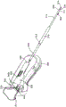
FIG. 7A is a perspective view of a fixation kit including an insertion instrument constructed in accordance with an alternative embodiment, the insertion instrument including a housing and a cannula extending from the housing and shown in a first configuration having a first anchor body and a second anchor body loaded into the insertion instrument;
FIG. 7B is an enlarged perspective view of the cannula of the insertion instrument shown in FIG. 7A;
FIG. 7C is a cross-sectional side elevational view of the housing of the insertion instrument illustrated in FIG. 7A;
FIG. 7D is an enlarged cross-sectional side elevational view of the cannula of the insertion instrument illustrated in FIG. 7A;
FIG. 8A is a perspective view of the fixation kit shown in FIG. 7A, with the insertion instrument shown in a second position to eject a second anchor body from the insertion instrument, the second anchor body shown in a first configuration;
FIG. 8B is an enlarged perspective view of the cannula of the insertion instrument shown in FIG. 8A;
FIG. 8C is a cross-sectional side elevational view of the housing illustrated in FIG. 8A;
FIG. 8D is a cross-sectional side elevational view of the cannula illustrated in FIG. 8A;
FIG. 9A is a perspective view of the fixation assembly shown in FIG. 8A, showing the insertion instrument in an offset position;
FIG. 9B is an enlarged perspective view of the cannula of the insertion instrument shown in FIG. 9A;
FIG. 9C is a cross-sectional side elevational view of the housing of the insertion instrument illustrated in FIG. 9A;
FIG. 9D is a cross-sectional side elevational view of the cannula of the insertion instrument illustrated in FIG. 9A;
FIG. 9E is a perspective view of the fixation kit shown in FIG. 9A, showing the second anchor body in an expanded configuration;
FIG. 10A is a perspective view of the fixation kit shown in FIG. 9A, showing the insertion instrument in an intermediate position after completion of the intermediate stroke;
FIG. 10B is an enlarged perspective view of the cannula of the insertion instrument shown in FIG. 10A;
FIG. 10C is a cross-sectional side elevational view of the housing of the insertion instrument illustrated in FIG. 10A;
FIG. 10D is a cross-sectional side elevational view of the cannula of the insertion instrument illustrated in FIG. 10A;
FIG. 11A is a perspective view of the fixation kit of FIG. 10A, showing the insertion instrument after the intermediate stroke when the first portion of the second stroke is completed;
FIG. 11B is an enlarged perspective view of the cannula of the insertion instrument shown in FIG. 11A;
FIG. 11C is a cross-sectional side elevational view of the housing of the insertion instrument illustrated in FIG. 11A;
FIG. 11D is a cross-sectional side elevational view of the cannula of the insertion instrument illustrated in FIG. 11A;
FIG. 12A is a perspective view of the fixation kit shown in FIG. 11A, showing the insertion instrument in a third position after completion of the second portion of the second stroke, ejecting the first anchor body from the insertion instrument, the first anchor body shown in the first configuration;
FIG. 12B is an enlarged perspective view of the cannula of the insertion instrument shown in FIG. 12A;
FIG. 12C is a cross-sectional side elevational view of the housing of the insertion instrument illustrated in FIG. 12A;
FIG. 12D is a cross-sectional side elevational view of the cannula of the insertion instrument illustrated in FIG. 12A;
FIG. 12E is a perspective view of the fixation kit similar to FIG. 12A, but with the first anchor body shown in an expanded configuration;
FIG. 12F is a cross-sectional side elevational view of the housing of the insertion instrument illustrated in FIG. 12A after release of the strand retaining mechanism;
FIG. 13A is a perspective view of the insertion instrument of FIG. 7A with a portion removed to illustrate the guidance system when the instrument is in the first position;
FIG. 13B is a perspective view of the insertion instrument of FIG. 8A, showing the guide system with the instrument in a second position;
FIG. 13C is a perspective view of the insertion instrument of FIG. 9A with a portion thereof removed to illustrate the guide system when the insertion instrument is in the biased position;
FIG. 13D is a perspective view of the insertion instrument of FIG. 10A with a portion thereof removed to illustrate the guidance system when the insertion instrument is in the neutral position;
FIG. 13E is a perspective view of the insertion instrument of FIG. 11A with a portion removed to illustrate the guidance system after the insertion instrument has completed the first portion of the second stroke;
FIG. 13F is a perspective view of the insertion instrument of FIG. 12A with a portion removed to illustrate the guidance system after the insertion instrument has completed a second portion of the second stroke;
FIG. 13G is a perspective view of a guide rail of the guidance system shown in FIG. 13A;
FIG. 14A is a perspective view of a coupling assembly constructed in accordance with one embodiment;
FIG. 14B is a cross-sectional side elevational view of the coupling assembly illustrated in FIG. 14A, shown in a first mode of operation;
FIG. 14C is a cross-sectional side elevational view of the coupling assembly illustrated in FIG. 14B, shown in a transitional state between the first mode of operation and the second mode of operation;
FIG. 14D is a cross-sectional side elevational view of the coupling assembly illustrated in FIG. 14C, shown in a second mode of operation;
FIG. 15A is a cross-sectional side elevational view of an insertion instrument constructed in accordance with another embodiment, showing the coupling assembly disposed in a first mode of operation;
FIG. 15B is a cross-sectional end elevation view of the coupling assembly shown in FIG. 15A taken along line 15B-15B;
FIG. 15C is a cross-sectional side elevational view of the insertion instrument illustrated in FIG. 15A, but showing the coupling assembly transitioning from the first mode of operation to the second mode of operation;
FIG. 15D is a cross-sectional end elevation view of the coupling assembly shown in FIG. 15C taken along line 15D-15D;
FIG. 15E is a cross-sectional side elevational view of the insertion instrument illustrated in FIG. 15C, but showing the coupling assembly in a second mode of operation;
fig. 16A is a schematic side elevational view of the anchor assembly shown in fig. 1G including a tensioning strand according to an alternative embodiment shown on the anchor body implanted in the first configuration;
FIG. 16B is a schematic side elevational view of the anchor assembly shown in FIG. 16A, but showing the implant anchor body in an expanded configuration;
FIG. 16C is a schematic side elevational view of the anchor assembly shown in FIG. 16B, showing another anchor body implanted in a first configuration;
FIG. 16D is a schematic side elevational view of the anchor assembly shown in FIG. 16C, showing another anchor body in an expanded configuration;
FIG. 16E is a schematic side elevational view of the anchor assembly as shown in FIG. 16D, illustrating locking of the locking member;
FIG. 16F is a schematic side elevational view of the anchor assembly as shown in FIG. 16E, shown in a final assembled configuration;
FIG. 17A is a perspective view of a strand retention assembly constructed in accordance with one embodiment, showing a releasable locking member;
FIG. 17B is a perspective view of the strand holding assembly shown in FIG. 17A, showing the locking member secured;
fig. 17C is a perspective view of the strand holding assembly shown in fig. 17A operably coupled to an actuator;
FIG. 17D is a perspective view of the strand holding assembly shown in FIG. 17C, shown in a released position;
fig. 18A is a schematic side elevation view of the anchor assembly shown in fig. 1G, including a pair of tensioning strands according to an alternative embodiment, showing the anchor body in a first configuration;
FIG. 18B is a schematic side elevational view of the anchor assembly shown in FIG. 18A, but showing the anchor body in an expanded configuration;
FIG. 18C is a schematic side elevational view of the anchor assembly as shown in FIG. 18B, illustrating actuation of the locking member and engagement of the dissection gap;
FIG. 18D is a schematic side elevational view of the anchor assembly as shown in FIG. 18C, illustrating locking of the locking member;
FIG. 18E is a schematic side elevational view of the anchor assembly as shown in FIG. 18D, shown in a final assembled configuration;
FIG. 19A is a schematic cross-sectional side elevational view of a retention assembly of an insertion instrument constructed in accordance with another embodiment, shown in a locked configuration;
FIG. 19B is a schematic cross-sectional side elevational view of the retention assembly of the insertion instrument illustrated in FIG. 19A, shown in an unlocked configuration;
FIG. 19C is a cross-sectional side elevational view of the housing of an insertion instrument similar to that shown in FIG. 12C, but including a retention assembly constructed in accordance with an alternative embodiment;
FIG. 20A is a cross-sectional side elevational view of an insertion instrument including a cutting assembly according to another embodiment, showing the cutting assembly in a disengaged position;
FIG. 20B is a cross-sectional side elevational view of the insertion instrument illustrated in FIG. 20A, but showing the cutting assembly in an engaged position;
FIG. 21A is a cross-sectional side elevational view of the insertion instrument as illustrated in FIG. 20A, but including a cutting assembly constructed in accordance with another embodiment and shown in a disengaged position;
FIG. 21B is a longitudinal cross-sectional view of the insertion instrument shown in FIG. 21A, but showing the cutting assembly in the engaged position;
FIG. 22A is a perspective view of the insertion instrument of FIG. 7A, but constructed in accordance with an alternative embodiment and shown in a first position;
FIG. 22B is a side elevational view of the insertion instrument illustrated in FIG. 22A;
FIG. 22C is a side elevational view of the insertion instrument illustrated in FIG. 22B, but shown in a second position;
FIG. 22D is a side elevational view of the insertion instrument illustrated in FIG. 22C, but shown in a third position;
FIG. 23A is a perspective view of an insertion instrument constructed in a similar manner to the insertion instrument shown in FIG. 7A, but constructed in accordance with another embodiment and shown in a first position;
FIG. 23B is a perspective view of the plunger of the insertion instrument shown in FIG. 23A;
FIG. 23C is a perspective view of the distal end of the insertion instrument shown in FIG. 23A;
FIG. 23D is a perspective view of various components of the insertion instrument shown in FIG. 23A, including the plunger, push rod, and pair of first coupling members shown in FIG. 23B;
FIG. 23E is a perspective view of a second coupling member configured to engage the first coupling member shown in FIG. 23D;
FIG. 23F is a perspective view of the insertion instrument illustrated in FIG. 23A, shown in a second position;
FIG. 23G is a perspective view of the insertion instrument illustrated in FIG. 23F, shown in an intermediate position;
FIG. 23H is a perspective view of the insertion instrument illustrated in FIG. 23G, shown in a third position;
FIG. 24A is a perspective view of an insertion instrument including a first pusher assembly and a second pusher assembly disposed in a side-by-side relationship, showing each pusher assembly in a first position;
FIG. 24B is a perspective view of the insertion instrument shown in FIG. 24A after the first locking tab is removed from the first pusher assembly;
FIG. 24C is a perspective view of the insertion instrument shown in FIG. 24B after actuation of the first pusher assembly to the second position;
FIG. 24D is a perspective view of the insertion instrument shown in FIG. 24C after the second locking tab is removed from the second pusher assembly;
FIG. 24E is a perspective view of the insertion instrument illustrated in FIG. 24D after actuation of the exchange actuator;
FIG. 24F is a perspective view of the insertion instrument shown in FIG. 24E after actuation of the second pusher assembly to the second position;
FIG. 25A is a perspective view of a component of the insertion instrument shown in FIG. 24A, showing each of the first and second pusher assemblies in a first position;
FIG. 25B is a perspective view of the components of the insertion instrument shown in FIG. 25A after the first pusher assembly has been actuated to the second position;
FIG. 25C is a perspective view of the components of the insertion instrument shown in FIG. 25B after actuation of the exchange actuator;
FIG. 25D is a perspective view of the components of the insertion instrument shown in FIG. 25C after the second pusher assembly has been actuated to the second position;
FIG. 26A is a perspective view of a retention assembly constructed in accordance with one embodiment;
FIG. 26B is an enlarged perspective view of a portion of the retention assembly shown in FIG. 26A;
FIG. 27A is a perspective view of an insertion instrument constructed in accordance with another embodiment, the insertion instrument including a first pusher assembly and a second pusher assembly disposed in a side-by-side relationship, showing each of the pusher assemblies in a first position;
FIG. 27B is a perspective view of the insertion instrument illustrated in FIG. 27A after actuation of the first pusher assembly to the deployed configuration;
FIG. 27C is a perspective view of the components of the insertion instrument shown in FIG. 27B after actuation of the swap actuator from the first position to the actuated position;
FIG. 27D is a perspective view of the insertion instrument illustrated in FIG. 27C after actuation of the second pusher assembly to the second position;
FIG. 28A is a perspective view of a component of the insertion instrument shown in FIG. 27A, shown with the exchange actuator in a first position;
FIG. 28B is a perspective view of a component of the insertion instrument shown in FIG. 28A, shown with the exchange actuator in a second position;
FIG. 29A is a perspective view of an insertion instrument constructed in accordance with another embodiment, the insertion instrument including a first pusher assembly and a second pusher assembly disposed in a side-by-side relationship, showing each of the pusher assemblies in a first position;
FIG. 29B is an end elevational view of the insertion instrument illustrated in FIG. 29A;
FIG. 29C is a perspective view of the insertion instrument illustrated in FIG. 29A, showing the first pusher assembly in a second position;
FIG. 29D is a perspective view of the insertion instrument illustrated in FIG. 29C after actuation of the swap actuator from the first position to the second position;
FIG. 29E is a perspective view of the insertion instrument illustrated in FIG. 29D after the locking tab is removed from the second pusher assembly;
FIG. 29F is a perspective view of the insertion instrument illustrated in FIG. 29E, showing the second pusher assembly in a second position;
FIG. 29G is a schematic cross-sectional end elevational view of the insertion instrument illustrated in FIG. 29D, showing a portion of the swap actuator;
FIG. 30A is a perspective view of an insertion instrument including first and second reciprocating cannulae constructed in accordance with another embodiment, the figure showing a portion of the housing cut away to expose internal components of the insertion instrument;
FIG. 30B is a perspective view of the reciprocating assembly of the insertion instrument shown in FIG. 30A, the reciprocating assembly configured to reciprocally drive the first cannula and the second cannula;
FIG. 30C is a perspective view of the drive member of the reciprocation assembly shown in FIG. 30B;
FIG. 30D is a perspective view of a selective plunger engagement assembly configured to selectively move a plunger between operable communication with a first cannula and operable communication with a second cannula;
FIG. 31 is a perspective view of an insertion instrument with a cannula defining a side ejection port according to another embodiment;
FIG. 32A is a perspective view of an access assembly including an access member and an opening-forming member, according to one embodiment;
FIG. 32B is a side cross-sectional view of the access member shown in FIG. 32A;
FIG. 32C is a side elevational view of the awl shown in FIG. 32A;
FIG. 32D is a side elevational view of a portion of the awl shown in FIG. 32C, according to an alternative embodiment;
FIG. 32E is a perspective view of the access assembly inserted into a target anatomical location;
FIG. 32F is a perspective view of the access member inserted into the target anatomical location;
FIG. 32G is a perspective view of an anchor inserter assembly including an access member, an anchor housing carrying an anchor, and a pusher member according to one embodiment;
FIG. 32H is a side cross-sectional view of the anchor housing shown in FIG. 32G;
FIG. 32I is a side cross-sectional view of the anchor inserter assembly shown in FIG. 32G with the anchor not yet ejected from the access member;
FIG. 32J is a side cross-sectional view of the pusher member shown in FIG. 32G;
FIG. 32K is a side cross-sectional view of the anchor inserter assembly shown in FIG. 32G with the pusher member advanced such that the anchor is ejected from the access member;
FIG. 32L is a perspective view of the anchor expanded with the target anatomical location;
FIG. 32M is a side cross-sectional view of an anchor assembly constructed in accordance with an alternative embodiment;
FIG. 33A is a perspective view of a anchor inserter assembly including an access member, an anchor housing carrying an anchor, and a tension assembly in accordance with an alternative embodiment;
FIG. 33B is a side elevational view of a component of the tension assembly shown in FIG. 33A;
FIG. 33C is a perspective view showing the components of the tension assembly shown in FIG. 33A before the tension assembly is operated to expand the anchor;
FIG. 33D is a perspective view showing the components of the tension assembly shown in FIG. 33A after the tension assembly has been manipulated to expand the anchor;
FIG. 34A is a perspective view of a anchor inserter assembly that includes an access member, an anchor housing that carries an anchor, and a tension assembly in accordance with an alternative embodiment;
FIG. 34B is a side cross-sectional view of a component of the tension assembly;
FIG. 34C is a partial cutaway perspective view showing the components of the tension assembly shown in FIG. 34A before the tension assembly is operated to expand the anchor;
FIG. 34D is a perspective view, partially in section, showing the components of the tension assembly shown in FIG. 34A after the tension assembly has been manipulated to expand the anchor;
FIG. 35A is an exploded perspective view of an access assembly according to an alternative embodiment, an anchor inserter assembly including an awl and an access member;
FIG. 35B is an exploded perspective view of a anchor inserter assembly including an access member, an anchor housing carrying an anchor, and a tension assembly in accordance with the alternative embodiment shown in FIG. 35A;
FIG. 36A is a perspective view of an access assembly including the awl and access member shown in FIG. 35;
FIG. 36B is a side cross-sectional view of the access assembly shown in FIG. 36A;
FIG. 37A is a perspective view of a anchor inserter assembly including the access member shown in FIG. 35, an anchor housing carrying the anchor, and a tension assembly, the anchor inserter assembly being configured to operate in a first mode;
FIG. 37B is a cross-sectional perspective view of the anchor inserter assembly shown in FIG. 37A;
FIG. 38 is a perspective view of the anchor inserter assembly shown in FIG. 37A, which is configured to operate in an anchor expansion mode with the translation member in the centered position;
FIG. 39 is a perspective view of the anchor inserter assembly shown in FIG. 38 with the translating member in the extended position;
FIG. 40A is a perspective view of a translating member constructed according to an alternative embodiment;
FIG. 40B is an elevation view of a translating member constructed according to an alternative embodiment;
FIG. 41A is a perspective view of a translating member constructed according to an alternative embodiment;
FIG. 41B is a front view of the translating member shown in FIG. 41A;
FIG. 42 is a cross-sectional elevation view of a translating member constructed according to an alternative embodiment;
FIG. 43 is a cross-sectional elevation view of a translating member constructed according to an alternative embodiment;
44A-44C illustrate various views of a clamp configured to secure an actuating member to a translating member;
FIG. 45 is a perspective view of an insertion instrument configured to insert and expand a pair of anchor bodies at respective target locations, the insertion instrument including a housing that in turn includes a first body and a second body, constructed in accordance with another embodiment;
FIG. 46 is an exploded perspective view of the first body, including the pusher member and the opening-forming member;
FIG. 47A is a perspective view of the first body illustrated in FIG. 46, shown in a retracted configuration;
FIG. 47B is a perspective view of the actuator of the first body shown in FIG. 47A, showing the actuator in a first position;
FIG. 47C is a perspective view of the distal end of the first body shown in FIG. 47A;
FIG. 48A is a perspective view of the first body illustrated in FIG. 46, shown in an extended configuration;
FIG. 48B is a perspective view of the actuator of the first body shown in FIG. 48A, showing the actuator in a second position;
FIG. 48C is a perspective view of the distal end of the first body shown in FIG. 48A;
FIG. 49A is a perspective view of an anchor cartridge constructed in accordance with one embodiment;
FIG. 49B is another perspective view of the anchor cartridge shown in FIG. 49A, portions of the anchor cartridge being hidden so as to show a pair of anchors supported by the anchor cartridge;
FIG. 50A is a top plan view of a portion of the insertion instrument illustrated in FIG. 45, showing the anchor cartridge illustrated in FIG. 49B in an initial position and an opening-forming member extending through the anchor cartridge;
FIG. 50B is a top plan view of the portion of the insertion instrument shown in FIG. 50A, but showing the opening-forming members retracted;
FIG. 50C is a top plan view of the portion of the insertion instrument shown in FIG. 50B, but showing the anchor cartridge disposed in a first position;
FIG. 50D is a top plan view of the portion of the insertion instrument shown in FIG. 50C, but showing the pusher member extending through the anchor cartridge;
FIG. 50E is a top plan view of the portion of the insertion instrument illustrated in FIG. 50D, but showing the pusher member retracted;
FIG. 50F is a top plan view of the portion of the insertion instrument illustrated in FIG. 50E, but showing the stop clip removed;
FIG. 50G is a top plan view of the portion of the insertion instrument shown in FIG. 50F, but showing the anchor cartridge in a second position;
FIG. 50H is a top plan view of the portion of the insertion instrument illustrated in FIG. 50G, but showing the pusher member extending through the anchor cartridge;
FIG. 51A is an exploded perspective view of a tension assembly (tension assembly) of the insertion instrument shown in FIG. 45;
FIG. 51B is a cross-sectional side elevational view of the tension assembly (tensioning assembly) shown in FIG. 51A, shown in a first position;
FIG. 51C is a cross-sectional side elevational view of the tension assembly shown in FIG. 51B taken at line 51C;
FIG. 51D is a cross-sectional end elevational view of the tension assembly as shown in FIG. 51B;
FIG. 51E is a cross-sectional side elevational view of the tension assembly illustrated in FIG. 51A, shown in a second position;
FIG. 51F is a cross-sectional side elevational view exploded view of the tension assembly shown in FIG. 51E taken at line 51F;
FIG. 51G is a cross-sectional side elevational view of the tension assembly illustrated in FIG. 51A, shown in a third position;
FIG. 51H is a cross-sectional side elevational view exploded view of the tension assembly shown in FIG. 51G taken at line 51H;
FIG. 51I is a cross-sectional end elevational view of the tension assembly as shown in FIG. 51G;
FIG. 52A is a perspective view of the insertion instrument illustrated in FIG. 45 configured for insertion into a first target site;
FIG. 52B is a perspective view of the insertion instrument illustrated in FIG. 52A shown inserted into a first target site to form a first opening;
FIG. 52C is a perspective view of the insertion instrument illustrated in FIG. 52B, but showing the open tip retracted;
FIG. 52D is a perspective view of the insertion instrument illustrated in FIG. 52C, but showing the pusher member retracted;
FIG. 53A is a perspective view of the insertion instrument shown in FIG. 52D, but showing the anchor cartridge in a first position;
FIG. 53B is a perspective view of the insertion instrument shown in FIG. 53A, but showing the first anchor body inserted into the first opening;
FIG. 53C is a perspective view of the insertion instrument shown in FIG. 53B, but showing the tensioning assembly actuated to expand the body of the inserted anchor;
FIG. 53D is a perspective view of the insertion instrument illustrated in FIG. 53C, but showing the tensioning assembly in a first position;
FIG. 53E is a perspective view of the insertion instrument illustrated in FIG. 53D, shown removed from the first target location;
FIG. 54A is a perspective view of the insertion instrument illustrated in FIG. 53E, the insertion instrument configured to be inserted into a second target location;
FIG. 54B is a perspective view of the insertion instrument illustrated in FIG. 54A shown inserted into a second target site to form a second opening;
FIG. 54C is a perspective view of the insertion instrument illustrated in FIG. 54B, but showing the open tip retracted;
FIG. 54D is a perspective view of the insertion instrument illustrated in FIG. 54C, but showing the pusher member retracted;
FIG. 55A is a perspective view of the insertion instrument illustrated in FIG. 54D, but showing the stop clip removed from the anchor cartridge;
FIG. 55B is a perspective view of the insertion instrument shown in FIG. 55A, but showing the anchor cartridge in a second position;
FIG. 55C is a perspective view of the insertion instrument shown in FIG. 55B, but showing the second anchor body inserted into the second opening;
FIG. 55D is a perspective view of the insertion instrument shown in FIG. 55C, but showing the tensioning assembly actuated to expand the inserted second anchor body;
FIG. 55E is a perspective view of the insertion instrument illustrated in FIG. 55D, but showing the tensioning assembly in a first position;
FIG. 55F is a perspective view of the insertion instrument illustrated in FIG. 55E, shown removed from a second target location;
fig. 56A is a side elevation view of an expandable anchor having an anchor body and an actuation strand, showing the anchor body in a first configuration, constructed in accordance with another embodiment;
FIG. 56B is a side elevational view of the expandable anchor shown in FIG. 56A, showing the anchor body in an expanded configuration;
FIG. 57A is a side elevational view of a first method step for forming the anchor body illustrated in FIG. 56A, showing the configuration of the eyelet;
57B-C illustrate method steps for forming the aperture shown in FIG. 57A, according to one embodiment;
FIG. 57D illustrates a method step for forming the aperture shown in FIG. 57A, in accordance with one embodiment;
FIG. 57E illustrates a method step for forming the aperture shown in FIG. 57A, in accordance with one embodiment;
57F-L illustrate method steps for forming the aperture shown in FIG. 57A, according to one embodiment;
FIG. 58A is a perspective view of a second method step for forming the anchor body shown in FIG. 56A, showing a first knot tying the eyelet shown in FIG. 57A around a mandrel;
FIG. 58B is another perspective view of the second method step shown in FIG. 58A;
fig. 58C is a perspective view of a third method step for forming the anchor body shown in fig. 56A, showing a second knot opposite the first knot;
FIG. 58D is another perspective view of the third method step shown in FIG. 58D;
FIG. 58E is a perspective view of a method step for forming the anchor body shown in FIG. 56A, showing a plurality of knots tied alternately relative to one another;
FIG. 58F is another perspective view of the method step shown in FIG. 58E;
FIG. 58G is a perspective view of the anchor body shown in FIG. 56A disposed about a mandrel;
FIG. 58H is a perspective view of the anchor body shown in FIG. 58G, showing an actuation strand inserted through the eyelet and through the mandrel;
fig. 58I is a perspective view of the anchor body and actuation strand shown in fig. 58H, showing the actuation strand driven through the anchor body;
Fig. 58J is a perspective view of the anchor body and actuating strand shown in fig. 58I, showing an eyelet driven through the anchor body;
FIG. 59 is a perspective view of an expandable anchor similar to that shown in FIG. 56A, but showing the knot of the anchor body configured as a breakaway knot, with the eyelet not yet pulled into the expandable portion of the anchor body;
FIG. 60A is a perspective view of an expandable anchor similar to that shown in FIG. 56A, but showing the anchor body including a pair of eyelets which will then be pulled into the expandable portion of the anchor body;
FIG. 60B is a perspective view of the expandable anchor shown in FIG. 60A, showing the anchor body in an expanded configuration;
FIG. 60C is a side view of an expandable anchor similar to that shown in FIG. 60A, but showing anchor body strand portions that may define eyelets; and is
Fig. 60D is a perspective view of the expandable anchor shown in fig. 60A, showing the anchor body in a closed position and a pair of eyelets.
Detailed Description
Referring first to fig. 1A-B, anchor assembly 20 can include at least one expandable anchor 22, such as first and second expandable anchors 22a and 22B, with first and second expandable anchors 22a and 22B including respective anchor bodies 28a and 28B, with anchor bodies 28a and 28B configured to be secured to an anatomical location, which can be defined by at least one anatomical structure 24. The anatomy 24 may be defined by, for example, an anatomy of a human or other animal, or an implant secured to or configured to be secured to an anatomy of a human or other animal. The anatomy may be defined by tissue, which may include at least one of bone and soft tissue (e.g., tendons, ligaments, cartilage, annulus fibrosus of intervertebral discs, etc.).
According to one embodiment, the at least one anatomical structure 24 may define a first target anatomical location 24a and a second target anatomical location 24b located on opposite sides of a gap, such as gap 24 c. Thus, the gap 24c may be disposed in an anatomical structure, and may, for example, define an anatomical defect, or may be disposed between different anatomical structures. First and second anchors 22a, 22b can be fired, or in other words driven or inserted, into respective first and second target anatomical locations 24a, 24b located on opposite sides of gap 24c, and then drawn toward one another to approximate gap 24 c. Alternatively or additionally, the anchor assembly 20 can be configured to secure an auxiliary structure to the anatomical structure. In this regard, it should also be understood that the anchor assembly 20 may include any number of anchors 22 as desired.
Each anchor body 28a and 28B can include a respective expandable portion 36a and 36B and an actuating member 37a and 37B, such as an actuating strand 38a and 38B, the actuating member 37a and 37B configured to actuate the respective expandable portion 36a and 36B, and the respective anchor body 28a and 28B, from a first configuration shown in fig. 1A to an expanded configuration shown in fig. 1B, with the anchor body 28a and 28B initially disposed at a target anatomical location via the first configuration shown in fig. 1A, and with the respective anchor body 28a and 28B securable to the anatomical structure 24 via the expanded configuration shown in fig. 1B. Accordingly, the anchor bodies 28a and 28b of the anchors 22a and 22b can be inserted through the openings 23 at the respective target anatomical locations 24a and 24b, which can be accomplished, for example, by firing the anchor bodies 28a and 28b into the respective target anatomical locations 24a and 24b, such as while delivering the anchor bodies 28a and 28b to the respective target anatomical locations 24a and 24 b.
The expandable portion 36 of the anchor body 28 extends along the elongation direction 34 to define an initial distance D1 measured along the elongation direction 34 from the proximal end 39a to the distal end 39b when in the first configuration. The initial distance D1 may be any length as desired, with the length being within a range having a lower end that may be defined by about 5mm, or about 10mm, or about 20mm, or about 24.5mm greater, and an upper end that may be defined by about 50mm, or about 40mm, or about 30mm, or about 25.5mm greater.
Further, in the first configuration, the expandable portion 36 defines an initial maximum thickness T1 extending in the second direction 35, the second direction 35 being substantially perpendicular relative to the elongation direction 34. The initial maximum thickness T1 may be sized as desired. As shown in fig. 1B, when the expandable portion 36 is in the expanded configuration, the expandable portion 36 contracts (e.g., compresses or entangles) in the direction of elongation 34 to a second distance D2 measured along the direction of elongation 34 from the proximal end 39a to the distal end 39B. The second distance D2 may be less than the initial distance D1. Upon contraction of the expandable portion 36 in the direction of elongation, such as upon actuation of the expandable portion 36 from the first configuration to the expanded configuration, the expandable portion 36 expands in the second direction 35 to a second maximum thickness T2 that is greater than the initial maximum thickness T1. The second maximum thickness T2 extends in a second direction 35 that is substantially perpendicular to the direction of elongation 34.
Maximum thicknesses T1 and T2 in the second direction 35 may be defined such that the anchor body 28 does not define a thickness in the second direction 35 that is greater than the maximum thicknesses T1 and T2, respectively. It should be appreciated that the proximal and distal ends 39a, 39b may change position on the expandable portion 36 as the expandable portion 36 is actuated to the expanded configuration, such as due to the configuration of the expandable portion 36 when in the expanded configuration. However, when the expandable portion 36 is in the expanded configuration, the proximal end 39a and the distal end 39b continue to define the proximal-most and distal-most ends of the expandable portion 36 such that a distance D2 along the elongation direction 34 is defined linearly between the proximal end 39a and the distal end 39b of the expandable portion 36 when the expandable portion 36 is in the expanded configuration.
Each of the actuating strands 38 of first and second anchors 22a, 22b may be attached to one another. For example, the actuating strand 38 of the first anchor 22a may be integral with the actuating strand 38 of the second anchor 22 b. Alternatively, as will be described in greater detail below in connection with fig. 2A-C, the actuation strand 38 of the first anchor 22A can be separated from the actuation strand 38 of the second anchor 22b such that the actuation strand 38 of the first anchor 22A and the actuation strand 38 of the second anchor 22b are then attached, directly or indirectly, using any suitable connector member 63. Connector member 63 may be integral with one or both of actuation strands 38a and 38b, or may be separately attached to either of actuation strands 38a and 38 b. According to one embodiment, the actuation strands 38a and 38b of each of the first and second anchors 22a and 22b define at least one respective actuation portion 131a and 131b, and may also include at least one respective attachment portion 133a and 133 b. Actuation portions 131a and 131b are each configured to receive an actuation force that causes actuation of respective anchors 22a and 22b from a first configuration to an expanded configuration.
According to the illustrated embodiment, the attachment portions 133a and 133b of the actuation strands 38a and 38b of the first and second anchors are configured to attach to one another, thereby spanning the gap 24c and attaching the first anchor body 28a to the second anchor body 28 b. The attachment portions 133a and 133b may be integral with one another or attached to one another using any suitable connector member. Further, according to the illustrated embodiment, the actuation portions 131a and 131b may also define attachment portions configured to attach to one another in any suitable manner before or after the actuation force F is applied to the actuation portions 131a and 131 b. Thus, attachment portions 133a and 133b of respective anchors 22a and 22b are configured to attach the respective anchor to another anchor (e.g., an attachment portion of another anchor). Further, actuating portion 131a of first anchor 22a is configured to attach the respective anchor 22a to second anchor 22 b. According to the illustrated embodiment, attachment portion 133a of actuating strand 38a of first anchor 22a is integral with attachment portion 133b of actuating strand 38b of second anchor 22b, but it should be understood that attachment portions 133a and 133b of first and second anchors 22a and 22b can be separate from and attached to one another as described in more detail below.
With continued reference to fig. 1A-B, once the expandable portions 36a-B of the anchors 22a-B have been actuated to the expanded configuration, the actuation strands 38a-B can be placed in tension. For example, according to one embodiment, an engagement force AF may be applied to either or both of the actuating portions 131a-b of the actuating strands 38a-b of the first and second anchors 22a-b, thereby inducing tension in the actuating strands 38a-b of the first and second anchors 22a-b to apply a biasing force that pulls the first and second anchors 22 a-22 b toward each other. Thus, if gap 24c is disposed between first anchor 22a and second anchor 22b, movement of anchors 22a and 22b toward one another in response to the biasing force will engage gap 24c, which in some embodiments, gap 24c may be an anatomical defect, such as a tissue defect as described above.
Further, when the actuating strands 38a-b are maintained in tension after the defect 24 has been engaged, the anchor bodies 28a-b are prevented from backing out of the anatomy through the respective target locations 24a-b, which may allow the gaps 24c to open 24 a-b. Thus, once gap 24c has been engaged, actuating strand 38a of first anchor 22a may be attached to actuating strand 38b of second anchor 22b in order to maintain tension between first anchor 22a and second anchor 22b and prevent first anchor 22a from separating from second anchor 22 b.
The anchor bodies 28a and 28b may be constructed by braiding any suitable substrate (e.g., strands, such as suture strands) in any desired manner that results in a plurality of openings 43 extending through the respective anchor bodies 28a and 28 b. The first and second actuation strands 38a and 38b may be braided through at least two of the openings 43 in the elongation direction 34 of the anchor bodies 28a and 28 b.
According to the embodiment shown in fig. 1A-1F, the first and second actuation strands 38a, 38b are integral with the respective first and second anchor bodies 28a, 28 b. According to other embodiments, the first and second actuation strands 38a, 38b are shown separate from and attached to the respective first and second anchor bodies 28a, 28b (see fig. 2C). According to other embodiments, one of the first and second actuation strands 38a, 38b is integral with the respective anchor body, and the other of the first and second actuation strands 38a, 38b is separate from and attached to the respective anchor body. According to embodiments in which the first and second actuation strands 38a, 38b are shown and described as being integral with the respective first and second anchor bodies 28a, 28b, it should be understood that, unless otherwise noted, the first and second actuation strands 38a, 38b may be either separate from the respective first and second anchor bodies 28a, 28b and attached to the respective first and second anchor bodies 28a, 28 b. Further, in accordance with embodiments in which the first and second actuation strands 38a, 38b are shown and described as being separate from and attached to the respective first and second anchor bodies 28a, 28b, it should be understood that the first and second actuation strands 38a, 38b may be either integral with the respective first and second anchor bodies 28a, 28b unless otherwise noted.
Referring to fig. 1C-1F, anchor assembly 20 can include at least one connector member 63, with the at least one connector member 63 configured to connect anchor 22 and allow a biasing force to be applied to at least one of anchors 22a and 22b to draw anchors 22a and 22b together to engage anatomical defect 24. Connector member 63 may be integral with one or both of first anchor 22a and second anchor 22b, such as with one or both of first actuation strand 38a and second actuation strand 38b, may be integral with one or both of the first anchor body and second anchor body, or may be separate from and attached (directly or indirectly) to one or both of first anchor 22a and second anchor 22 b. For example, as will be described in greater detail below, connector member 63 may be separate from first anchor 22a and second anchor 22b and attached between first anchor 22a and second anchor 22 b. Although connector member 63 is described herein according to various embodiments, it should be understood that anchor assembly 20 may alternatively include any suitable connector member configured to attach first anchor 22a to second anchor 22 b.
The anchor assembly 20 may include a connector member 63 integral with the corresponding actuation strands 38a and 38 b. As described above, each of the first and second anchor bodies 28a, 28b can be implanted at respective first and second target anatomical locations 24a, 24b disposed on opposite sides of the gap 24c as shown in fig. 2A. Each of the first and second actuation strands 38a and 38b may receive an actuation force F substantially along the elongation direction 34 that actuates the respective first and second anchor bodies 28a and 28b (specifically the respective expandable portions 36a and 36b) from the first configuration to the expanded configuration, thereby securing the first and second anchor bodies 28a and 28b at the respective first and second target anatomical locations 24a and 24 b. The actuation force F applied to each of the actuation strands 38a and 38b may be in the form of a different actuation force, or may be the same actuation force.
For example, referring to fig. 1C-1D, the connector member 63 may be configured as an auxiliary connector member 77, i.e., a connector member that is separate from one or both of the first and second actuation strands 38a, 38b, and configured to attach the first and second actuation strands 38a, 38b to one another. For example, the auxiliary connector member 77 may be made of any suitable metal, plastic, or any alternative biocompatible material, and may be configured as a body 146, which may be flexible or rigid, which body 146 may be configured to attach to either or both of the first and second actuation strands 38a, 38b, particularly to the actuation portions 131a-b, at a location between the anchors 22a and 22 b. For example, each of the first and second actuating portions 131a, 131b may be stitched through the body 146 and tied around the body 146, thereby defining a knot 148 that may be actuated from an unlocked to a locked configuration. The first and second actuating portions 131a, 131b are slidable relative to the body 146 when the knot 148 is in the unlocked configuration and are fixed relative to the sliding movement of the opposing body 146 when the knot 148 is in the locked configuration. The body 146 may define any shape as desired, such as a generally cylindrical shape, and may be flexible or generally rigid as desired.
During operation, actuating portions 131a-b may be sutured through body 146 in a direction away from anatomical structure 24 and tied around body 146 such that respective knot 148 is in an unlocked configuration. The body 146 may be oriented such that its long axis 149 is oriented substantially parallel to the anatomical structure 24. While the actuation strands 38a and 38b are under tension, the body 146 may be translated along the first and second actuation strands 38a and 38b toward the anatomical structure 24 in the direction of arrow 150, which causes the actuation strands 38a and 38b to translate relative to the body 146 in the opposite direction indicated by arrow 152. As the body 146 translates along the actuation strands 38a and 38b toward the gap 24c, the body 146 applies an actuation force F to the actuation strands 38a and 38b, which in turn actuates the anchors 22a and 22b from the first configuration to the expanded configuration.
As the body is further translated toward the gap 24c after the anchors 22a and 22b have been actuated to their expanded configurations, the body 146 applies an engagement force AF to at least one or both of the actuation strands 38a and 38b to pull at least one or both of the anchors 22a and 22b inward toward the other, thereby engaging the gap 24 c. In this regard, it should be appreciated that the engagement force AF may be a continuation of the actuation force F. Alternatively, the actuation force F may be applied to the actuation strands 38a and 38b at a location upstream of the main body 146 or prior to attaching the actuation strands 38a and 38b to the main body 146. The knot 148 may then be tightened to secure the first and second actuation strands 38a, 38b to the body 146 and thus also secure the first and second actuation strands 38a, 38b to one another, thereby preventing the first anchor 22a from separating from the second anchor 22 b. Once the gap 24c has been engaged, the body 146, and thus the knot 148, may be disposed along an outer surface of the anatomical structure 24. Alternatively, the body 146 can be sized such that once the gap 24c has been engaged, a portion of the body 146, and thus the knot 148, is disposed in the opening 23 that receives the anchor bodies 28a and 28 b. Thus, the knot 148 may be disposed behind the anatomical structure 24, or may be embedded in the anatomical structure 24.
The body 146 may thus define a sliding member 47, and may also define a locking member 64, the sliding member 47 allowing one of the first and second actuation strands 38a, 38b to slide relative to the other of the first and second actuation strands 38a, 38b to engage the gap 24c, and the locking member 64 securing the first and second actuation strands 38a, 38b to one another, such as relative movement allowing separation of the first and second anchors 28a, 28 b.
Referring now to fig. 1E-1F, anchor assembly 20 can include a pair of connector members 63a and 63b configured to attach at least one or both of actuating portions 131a and 131b to respective attachment portions 133a and 133 b. According to the illustrated embodiment, the actuation strands 38a and 38b are defined by a common actuation member (e.g., a common strand) that may be a secondary strand 33, the secondary strand 33 being separable from the first and second anchor bodies 28a and 28b and braided through at least one (e.g., one or more) openings in the first and second anchor bodies 28a and 28b such that the respective attachment portions 133a and 133b are integral with one another. Thus, according to the illustrated embodiment, the first and second actuation strands 38a, 38b are integral with one another. Anchor assembly 20 may include first and second connector members 63a and 63b defined by actuation strands 38a and 38b and configured to attach actuation portions 131a and 131b to other locations of the common strand, and thus to each other. According to the illustrated embodiment, the first connector member 63a may attach the corresponding first actuation portion 131a to another location of the auxiliary strand 33 spaced apart from the first actuation portion 131 a. Likewise, the second connector member 63b may attach the corresponding second actuation portion 131b to another location of the secondary strand 33 spaced apart from the second actuation portion 131 b. For example, according to the illustrated embodiment, the first connector member 63a attaches the first actuating portion 131a to the first attachment portion 133a, and the second connector member 63b attaches the second actuating portion 131b to the second attachment portion 133 b.
Thus, it can be said that at least one connector member, such as the first and second connector members 63a and 63b, can attach the first and second actuation portions 131a and 131b to respective other locations of the secondary strand 33, such that the first and second actuation portions 131a and 131b are attached to each other, for example indirectly, by at least one or both of the attachment portions 133a and 133 b. It can also be said that the first connector member 63a operatively attaches a portion of the first actuation strand 38a to another location of the first actuation strand 38a, while the second connector member 63b operatively attaches a portion of the second actuation strand 38b to another location of the second actuation strand 38 b. Alternatively, it should be understood that first and second connector members 63a and 63b can attach respective first and second actuating portions 131a and 131b to anchor body 28, such as at respective first and second end portions 52 and 54. Although the actuation strands 38a and 38b are shown as being separate from one another, the actuation strands 38a and 38b may be attached to one another, either via any suitable connector member 63 of the type described herein, for example, thereby defining an outer connector strand.
According to the illustrated embodiment, each of the first and second connector members 63a and 63b may be configured as respective knots 66a and 66b defined by the secondary strands 33. According to the illustrated embodiment, the first knot 66a includes a trailing end 68 and a free end, the trailing end 68 may be defined by the actuating portions 131a of the first actuating strands 38a, the free end may include a static portion 70a defined by the first ends 137a of the first actuating portions 133a, and a free portion 70b defined by the second ends 139a of the first actuating portions 133 a. The first end 137a can be disposed between the knot 66a and the first anchor body 28a, while the second end 139a can be disposed between the knot 66a and the second connector member 63 b. Alternatively, the free portion 70b may be defined by the attachment portion 133b of the second actuation strand 38 b.
According to one embodiment, the second knot 66b includes a trailing end 68 and a free end, the trailing end 68 may be defined by the actuating portion 131b of the second actuating strand 38b, the free end may include a static portion 70a defined by a first end 137b of the second actuating portion 133b, and a free portion 70b defined by a second end 139b of the second actuating portion 133 b. The first end 137b can be disposed between the knot 66b and the second anchor body 28b, and the second end 139b can be disposed between the knot 66b and the first connector member 63 a. Alternatively, the free portion 70b may be defined by the attachment portion 133a of the first actuation strand 38 a. The attachment portions 133a and 133b are shown as being integral with one another, but it should be understood that the attachment portions 133a and 133b can be separate from and attached to one another as desired.
Each of the first and second knots 66a, 66b may define a respective sliding member 47, the sliding member 47 allowing the respective trailing end 68 to translate therethrough relative to the free end. Thus, sliding member 47 allows first and second actuating portions 131a and 131b to translate relative to first and second actuating portions 133a and 133b, for example, in response to an actuation force F applied when knots 66a and 66b are in an unlocked configuration, thereby actuating respective anchor bodies 28a and 28b from a first configuration to an expanded configuration. Each knot 66 also defines a locking member 64 that is actuatable to a locked configuration, thereby securing at least one or both of the anchors 22a and 22b in their respective biased positions. For example, a stretch locking force may be applied to free portion 70b of the free ends of knots 66a and 66b to prevent actuation portions 131a and 131b from translating through knots 66a and 66b relative to attachment portions 133a and 133 b.
The distance L between the first knot 66a and the second knot 66b may be substantially equal to or less than the distance between the target anatomical locations 24a and 24b such that the gap 24c is engaged when the first and second anchors 22a and 22b expand behind the anatomy and are joined by the auxiliary strand 33 such that the tension created in the actuation strands 38a and 38b maintains engagement of the gap 24 c. Although the first and second connector members 63a, 63b may be configured as respective knots 66, it should be understood that either or both of the first and second connector members 63a, 63b may be configured as any suitable locking member 63 of any of the types described herein, or alternatively configured. For example, at least one or both of the connector members 63a-b may define an engagement whereby the respective actuation strands 38a-b may be engaged by another of the actuation strands 38a-b or by itself, and upon actuation of the anchors 22a and 22b, the connector strands are placed under tension to exert a compressive force that prevents translation of the anchor strands 38 a-b.
It should be understood that the anchor bodies 28a and 28b may be configured according to any suitable embodiment as desired. For example, referring now to fig. 1G-1H, each of the anchor bodies 28a and 28b can include an eyelet 90 extending from the distal end of the respective expandable portion 36a and 36 b. The actuation strand 38 may be configured as a secondary strand 33 separate from the anchor body 28. The actuation strands may be braided through the anchor bodies 28a and 28b and may extend through the respective eyelets 90a and 90b for defining a path for the eyelets 90a and 90b to travel through the respective anchor bodies 28a and 28b when the anchor bodies 28a and 28b are actuated from the first configuration to the expanded configuration. The auxiliary strands 33 can thus attach the first anchor body 28a to the second anchor body 28b, and can also be configured to receive an actuation force F that actuates the anchor bodies 28a and 28b from the first configuration to the expanded configuration once implanted at the respective target anatomical locations 24a and 24 b.
As described above, the anchor assembly 20 can include any suitable connector member 63, and the connector member 63 can be configured to attach to the first and second actuation portions 131a and 131b, thereby attaching the first and second actuation strands 38a and 38b to one another, and also attaching the anchors 22a and 22b to one another. The first and second actuation strands 38a, 38b are shown as being integral with one another and thereby define a common actuation strand. Alternatively, the first and second actuation strands 38a, 38b may be separate from one another and attached to one another in any desired manner.
According to the embodiment shown in fig. 1G-H, the connector member 63 is defined by the first and second actuation strands 38a, 38b and is integral with the first and second actuation strands 38a, 38 b. Thus, the actuation portions 131a and 131b of the actuation strands 38a and 38b are directly attached to each other. The connector member 63 may define a sliding member 47 and a locking member 64 at a junction 125. For example, the connector member 63 may define a knot 66, which knot 66 may be configured as desired, and may be defined by one or both of the actuation strands 38a and 38 b. Thus, at least a portion of connector member 63 may be integral with at least one or both of actuation strands 38a and 38 b.
One of the first and second actuation strands 38a, 38b may define a trailing end 68 of the knot 66, and the other of the first and second actuation strands 38a, 38b may define a free end 70 of the knot 66. According to the illustrated embodiment, the first actuation strand, e.g., first actuation portion 131a, defines a trailing end 68, while the second actuation strand 38b, e.g., second actuation portion 131b, defines a free end 70.
Prior to applying tension to the actuation strands 38a and 38b, biasing the first and second anchors 22a and 22b toward each other and engaging the gap 24c, the first and second actuation strands 38a and 38b may be tied into a knot 66. Once the knot 66 is formed, and when the knot 66 is in the unlocked configuration, an actuation force F may be applied to the actuation strands 38a and 38b, and in particular to the actuation portions 131a-b, in order to actuate the respective expandable portion 36 from the first configuration to the expanded configuration. Next, an engagement force AF may be applied to the terminal portion 135a of the first actuation strand 38a defining the rear strand 68, thereby sliding the rear end 68 through the knot 66 and pulling the respective anchor, e.g., first anchor 22a, toward the other anchor, e.g., second anchor 22 b. Once the gap 24c has been engaged, the free strand 70b of the free end 70, e.g., defined by the terminal portion 135b of the second actuation strand 38b, may be placed under tension to lock the knot 66 and prevent the first actuation strand 38a from translating through the knot 66, thereby securing the actuation strands 38a and 38b under tension. While the connector member 63 may be configured as a knot 66, it should be understood that the connector member 63 may be configured with any suitable alternative connector, either according to any of the embodiments described herein or as desired.
Referring now to fig. 2A-C, and as generally described above with respect to fig. 1A-B, anchor assembly 20 may include a first anchor 22A and a second anchor 22B. The first anchor 22a includes a first anchor body 28a that extends substantially along the direction of elongation 34 and defines a first plurality of openings 40a that extend through the first anchor body 28 a. The first anchor 22a also includes a first actuation strand 38a that extends through at least one of the openings 40a, such as a plurality of openings, and is configured to receive an actuation force F that actuates the first anchor body 28a from the first configuration to the expanded configuration in the manner described above. The first actuation strand 38a may be separate from the first anchor body 28a and attached to the first anchor body 28a, such as braided through an opening of the first anchor body 28a, or may be integral with the first anchor body 28a and extend through an opening of the first anchor body 28 a.
The second anchor 22b includes a second anchor body 28b that extends substantially along the direction of elongation 34 and defines a second plurality of openings 40b that extend through the second anchor body 28 b. The second anchor 22b also includes a second actuation strand 38b that extends through at least one of the openings 40b (e.g., a plurality of openings) and is configured to receive an actuation force F that actuates the second anchor body 28b from the first configuration to the expanded configuration in the manner described above. The second actuation strand 38b may be separate from the second anchor body 28b and attached to the second anchor body 28b, such as braided through an opening of the second anchor body 28b, or may be integral with the second anchor body 28b and extend through an opening of the second anchor body 28 b.
According to the embodiment shown in fig. 2A-B, the first and second actuation strands 38a, 38B are integral with the respective first and second anchor bodies 28a, 28B. According to other embodiments, the first and second actuation strands 38a, 38b are shown separate from and attached to the respective first and second anchor bodies 28a, 28 b. According to other embodiments, one of the first and second actuation strands 38a, 38b is integral with the respective anchor body, and the other of the first and second actuation strands 38a, 38b is separate from and attached to the respective anchor body. According to embodiments in which the first and second actuation strands 38a, 38b are shown and described as being integral with the respective first and second anchor bodies 28a, 28b, it should be understood that, unless otherwise noted, the first and second actuation strands 38a, 38b may be either separate from the respective first and second anchor bodies 28a, 28b and attached to the respective first and second anchor bodies 28a, 28 b. Further, in accordance with embodiments in which the first and second actuation strands 38a, 38b are shown and described as being separate from and attached to the respective first and second anchor bodies 28a, 28b, it should be understood that the first and second actuation strands 38a, 38b may be either integral with the respective first and second anchor bodies 28a, 28b unless otherwise noted.
With continued reference to fig. 2C, anchor assembly 20 can include at least one connector member 63 configured to connect anchor 22 and allow a biasing force to be applied to at least one of anchors 22a and 22b to draw anchors 22a and 22b together to engage anatomical defect 24. Connector member 63 may be integral with one or both of first anchor 22a and second anchor 22b, such as with one or both of first actuation strand 38a and second actuation strand 38b, may be integral with one or both of the first anchor body and second anchor body, or may be separate from and attached (directly or indirectly) to one or both of first anchor 22a and second anchor 22 b. For example, as will be described in greater detail below, connector member 63 may be separate from first anchor 22a and second anchor 22b and attached between first anchor 22a and second anchor 22 b. Although connector member 63 is described herein according to various embodiments, it should be understood that anchor assembly 20 may alternatively include any suitable connector member configured to attach first anchor 22a to second anchor 22 b. At least one or both of the actuation strands 38a-b may be configured to receive an engagement force AF that biases at least one of the first and second anchors 22a, 22b toward the other so as to engage the gap 24 c.
The anchor assembly 20 may include a connector member 63 integral with the corresponding actuation strands 38a and 38 b. As described above, each of the first and second anchor bodies 28a, 28b can be implanted at respective first and second target anatomical locations 24a, 24b disposed on opposite sides of the gap 24c as shown in fig. 2A. Each of the first and second actuation strands 38a and 38b can receive an actuation force F substantially along the elongation direction 34 that actuates the respective first and second anchor bodies 28a and 28b, and in particular the respective expandable portions 36a and 36b, from the first configuration to the expanded configuration in order to secure the first and second anchor bodies 28a and 28b at the respective first and second target anatomical locations 24a and 24 b. The actuation force F applied to each of the first and second actuation strands 38a, 38b may be in the form of different actuation forces, or may be the same actuation force as described in more detail below.
Referring now to fig. 2B, once the first and second anchor bodies 28a, 28B are secured to the respective first and second target anatomical locations 24a, 24B, an engagement force AF may be applied to at least one or both of the first and second actuation sections 38a, 38B substantially in a direction toward the other of the respective first and second anchor bodies 28a, 28B, which may also be toward the respective gap 24 c. Thus, the engagement force AF can have a vector that is directed toward the other of the respective first and second anchor bodies 28a, 28b, e.g., can be directed simply toward the other of the first and second anchor bodies 28a, 28 b. Likewise, the engagement force AF may have a vector that points toward the gap 24c (e.g., points simply toward the gap 24 c). Thus, the engagement force AF biases at least one or both of the anchor bodies 28a and 28b toward the other of the anchor bodies 28a and 28b to a respective biased position to engage the gap 24 c.
Referring again to fig. 2C, a connector member 63, which may define at least one or both of the sliding member 47 and the locking member 64, attaches the first and second connector actuation strands 38a, 38b together, for example, at a junction 125. Thus, it should be understood that at least one of the sliding member 47 and the locking member 64 may likewise attach the first actuation strand 38a to the second actuation strand 38 b. According to one embodiment, the connector member 63 may attach the first and second actuation strands 38a, 38b after the first and second actuation strands 38a, 38b have been under tension to maintain the gap 24c in an engaged state. Member 63 can be actuated to a locked configuration to prevent or resist separation of first anchor 22a from second anchor 22b which would open gap 24c from the engaged condition. Alternatively or additionally, the connector member 63 may attach the first and second actuation strands 38a and 38b to one another prior to applying the engagement force AF to the actuation strands 38a and 38b and placing the actuation strands 38a and 38b under tension, and thus prior to engaging the gap 24 c.
According to certain embodiments, the connector member 63 is defined by and integral with the first and second actuation strands 38a, 38b and may be configured as a repeatedly slidable and locked knot between an unlocked configuration, by which one of the actuation strands 38a, 38b may slide relative to the other to engage the gap 24c, and a locked configuration, by which the actuation strands 38a, 38b are prevented from sliding through the knot relative to each other. The connector member 63 defines at least one of the slide member 47 and the lock member 64 at a junction 125. Thus, it can be said that the connector member 63 can directly or indirectly attach the first and second actuation strands 38a, 38b together.
Referring now to fig. 3A, fixation assembly 250 may include anchor assembly 20, e.g., at least one anchor 22, and insertion instrument 252 configured to fire anchor 22 into anatomical structure 24 as shown in fig. 1A-B. It should be understood that fixation kit 250 may include at least one anchor 22 or more or even all of the anchors 22 described individually herein that are attached to each other or are configured to be attached to each other according to any of the embodiments described herein. Insertion instrument 252 may include a cannula 254 having a central opening 256 and a first pusher member, such as a plunger or push rod 25, which may be coaxially inserted into central opening 256. The cannula 254 has a sharp tip 260 and a slot 268 extending axially from the tip 260. The cannula 254 may extend substantially straight as shown, or may be curved, or define any suitable shape as desired for ejection of the anchor body 28.
In addition, the insertion instrument 252 includes a handle 262 having a lever 264. One end of the handle 262 is removably attached to the cannula 254 and the lever 264 is removably attached to the plunger 258. The outer diameter of the plunger 258 corresponds to the inner diameter of the central opening 256 of the cannula 254. At the rear end, the central opening of the cannula 254 is conically configured in such a way that it enlarges at the inlet 266 towards the rear end of the cannula 254. Thus, the anchor body 28 of the anchor 22 may be inserted through the conical inlet 266 and into the central opening 256 of the cannula 254 in its first configuration such that the anchor body 28 is capable of being compressed.
Upon pressing the anchor body 28 out of the cannula 254 by pressing the plunger 258 forward, the anchor body 28 may expand radially, for example, in the second direction 35 (see fig. 1A-B) in such a way that the anchor body 28 may be retained by the anterior surface of the cannula 254 when tension is applied to the actuation strand 38 to tighten the anchor body 28. The actuation strand 38 is guided through the slot 268 such that when the cannula 254 is inserted into the anatomical structure 24, the actuation strand 38 can be guided alongside the cannula 254. A needle 270 is attached at the free end of the actuation strand 38, the needle 270 being useful for ending the surgical procedure when the anchor body 28 of the anchor 22 has been actuated to the expanded configuration and secured to the anatomical structure 24.
Referring to fig. 3B, the plunger 258 may have an outer diameter or an optional cross-sectional dimension that is less than an inner diameter or a cross-sectional dimension of the central opening 256 of the cannula 254. Thus, when the plunger 258 is inserted into the central opening 256 of the cannula 254, the actuating strands 38 of the anchor 22 may be directed through the central opening 256 of the cannula 254. By actuating the lever 264 at the handle 262, the plunger 258 can push the anchor 22 forward in the cannula 254 until the anchor body 28 exits the central opening 256 at the tip 260 of the cannula 254. Once the anchor body 28 is positioned in the central opening 256, the actuation strand 38 may be pulled back at the rear end of the cannula 254 so that the anchor body 28 may be actuated to its expanded configuration in the cavity 256.
Referring to fig. 4A-D, the plunger 258 can define a central bore 272, which can guide the actuation strand 38 of the anchor 22 through the central bore 272. In addition, the cannula 254 has a first longitudinal bore 274 extending between the tip 260 and the rear end of the cannula 254 such that the cannula 254 is slotted throughout its length. A second longitudinal bore 276 extends through the plunger 258 between the forward and rearward ends of the plunger 258 such that the plunger 258 is also slotted throughout its length. As shown in fig. 4B, the first longitudinal bore 274 of the cannula 254 is diametrically opposed to the second longitudinal bore 276 of the plunger 258 when the cannula 254 is in a first rotational position relative to the plunger 258. In the first rotational position of the cannula 254, the actuating strand 38 of the anchor 22 is retained by the central bore 272. Once the anchor body 28 of the anchor 22 is secured in the body cavity of the patient by pulling back the actuating strand 38 of the anchor 22, the cannula 254 can be rotated to a second rotational position relative to the plunger 258 (fig. 4D). In this second rotational position of the cannula 254, the first longitudinal bore 274 of the cannula 254 is aligned with the second longitudinal bore 276 of the plunger 258 and the insertion instrument 252 can be released from the actuating strand 38 of the anchor 22.
Fig. 5A-D illustrate a handle 262, and the attachment of the cannula 254 to the handle 262 of the embodiment of the insertion instrument 252 of fig. 3A-4D. The upper end portion of the handle 262 includes a spring member, such as a leaf spring 279 and a groove 278 into which the cannula 254 may be inserted to provide a releasable snap lock configured to releasably attach the cannula 254 to the handle 262. The rear end of the plunger 258 may snap into a resilient prong 280 disposed at the upper end of the lever 264.
Referring to fig. 6, the insertion instrument 52 may include a depth control tube 282 and a clamping element 284 that slide over the cannula 254. Insertion instrument 52 is preoperatively prepared by inserting anchor 22 into cannula 254 and inserting plunger 258. Once anchor 22 and plunger 258 have been inserted, any one of a plurality of gripping elements 284 is attached to the rear end of insertion instrument 252 by snapping first tab 286 onto the rear of cannula 254. To prevent accidental displacement of the plunger 258 relative to the cannula 254, the clamping element 284 includes a second tab 288 adjacent the rear end of the cannula 254 and a third tab 290 adjacent the enlarged portion at the rear end of the plunger 258. Prior to use of insertion instrument 252, clamping element 284 is removed from cannula 254 and handle 262 is attached to cannula 254, and insertion instrument 252 may be operated in the manner described herein.
Referring now to fig. 1A and 7A-D, an insertion instrument 300 constructed in accordance with an alternative embodiment is configured to deliver at least one anchor knot, e.g., first anchor knot 22a and second anchor knot 22b, to respective target locations, e.g., target locations 24a and 24b (fig. 1A). The insertion instrument 300 is shown as being elongated along a longitudinal axis 302 (which extends substantially along the longitudinal direction L) and defines a proximal end 304 and an opposite distal end 306 spaced from the proximal end 304 along the longitudinal axis 302. Accordingly, it should be understood that the terms "distal" and "proximal" and derivatives thereof refer to spatial orientations closer to the distal end 306 and the proximal end 304, respectively. Further, the directional terms "downstream" and "upstream" and derivatives thereof refer to a direction extending from proximal end 304 toward distal end 306, and a direction extending from distal end 306 toward proximal end 304, respectively. The insertion instrument 300 also extends in a lateral direction a that is substantially perpendicular to the longitudinal direction L, and a transverse direction T that is substantially perpendicular to the longitudinal direction L and the lateral direction a. It can also be said that the lateral direction a and the transverse direction T extend radially with respect to the longitudinal axis 302. Thus, the terms "radially outward" and "radially inward," and derivatives thereof, refer to directions away from and toward, respectively, the longitudinal axis 302, and may be used synonymously with lateral and transverse directions, as desired.
Once second anchor 22b has been ejected from ejection port 442, plunger 316 is configured to translate further distally along the first portion of the second stroke shown in fig. 11A-C and along the second portion of the second stroke shown in fig. 12A-C such that pusher bar 330 (see fig. 7C) biases first anchor body 28a distally to eject first anchor 22A from cannula 310 (e.g., from ejection port 442) and into first target anatomical location 22A. Alternatively, as described in greater detail below, cannula 310 may define a side ejection port 318 (described below in connection with fig. 31) configured to eject first and second anchor bodies 28a, 28b from cannula 310 in a direction angularly offset relative to central axis 309.
The insertion instrument 300 may be configured such that the plunger 316 moves distally from the second position to the offset position shown in fig. 9A-D before moving from the offset position to the intermediate position shown in fig. 10A-D along an intermediate stroke. Thus, the plunger 316 may be moved from the second position to the offset position, to the intermediate position, and finally to the third position shown in fig. 12A-D. According to the illustrated embodiment, the plunger 316 rotates from the second position to the intermediate position before translating to the third position along the second stroke. For example, the plunger 316 may move along the first portion of the second stroke shown in FIGS. 11A-D before moving along the second portion of the second stroke shown in FIGS. 12A-D. The actuation force may be applied to actuation portions 131a and 131b of first and second anchors 22a and 22b, respectively, after each anchor has been ejected, or alternatively may be applied after both anchors 22a and 22b have been ejected. Anchors 22a and 22b may be attached to each other in any manner as desired, such as across gap 24 c.
Referring now to fig. 7A-C, specifically, the housing 308 defines a body 320 that defines at least one radially outer sidewall 322, such as a plurality of connected walls that may be of any size and shape, and further defines a proximal wall 324 and an opposing distal wall 326. The at least one outer wall 322, the proximal wall 324, and the distal wall 326 at least partially define an interior 328 that is fluidly communicable with the elongate opening 312 of the cannula 310. The cannula 310 is attached to the distal wall 326 of the housing 308 and is thus fixed to the housing 308. Cannula 310 extends distally from housing 308 to a tip 311. The tip 311 may be distally tapered such that the cannula 310 defines a tapered distal end. For example, the tip 311 may be conical, i.e., the tip 311 may define a portion that is conical, and may define a conical shape or any suitable alternative shape as desired. The insertion instrument 300 may further include a support sleeve 313 that at least partially surrounds the cannula 310 at an interface with the housing 308 and extends distally along a portion of the length of the cannula 310. Support sleeve 313 provides structural support and rigidity to cannula 310.
Because pusher bar 330 is translatably secured to plunger 316, proximal and distal movement of plunger 316 will cause pusher bar 330 to likewise move proximally and distally. The push rod 330 defines a distal end 330a disposed in the opening 312 of the cannula 310. Accordingly, distal end 330a of pushing rod 330 is configured to abut first anchor 22a when insertion instrument 300 is in the first position as shown in fig. 7A-D. The distal end 330a of the pusher bar 330 is configured to abut the first anchor 22a when the insertion instrument 300 is in the first position, and when the plunger 316, and thus the pusher bar 330, translates distally from the first position to the second position, such that the pusher bar 330 ejects the first anchor 22a from the insertion instrument 300 and into the corresponding target location 24 a. When tension is applied to the respective actuating member 37a substantially in the elongated direction of the anchor body 28a after the first anchor body 28a has been ejected and abutted against the anatomical structure 24, the anchor body 28a expands in a second direction 35 perpendicular relative to the elongated direction 34 of the anchor body 28a (see, e.g., fig. 1A-B).
The push tube 334 may include a plug 314 configured to define a distal end of the push tube 334. The push tube 334 may be hollow according to the illustrated embodiment so as to define a longitudinally elongated opening 335, and the push rod 330 has an outer diameter that is less than the outer diameter of the opening 335 such that the push rod 330 is disposed within the elongated opening 335 of the push tube 334. It should be understood that a structure described herein as defining a diameter may alternatively define any suitably configured cross-section, which may be circular or alternatively shaped, and thus may define any cross-sectional dimension that can be a diameter or a non-diameter. The cannula 310 can house the first anchor body 28a and the second anchor body 28 b. For example, the push tube 334 may receive the first anchor body 28a at a location upstream of the plug 314, and the cannula 310 may receive the second anchor body 28b at a location distal of the plug 314, and in turn, distal of the first anchor body 28 a.
The collar 332, and thus the push tube 334, includes the plug 314, is configured to be selectively coupled to and decoupled from the first pusher assembly 317 with respect to translation, and is configured to be selectively coupled to and decoupled from the housing 308 with respect to translation. For example, in the first configuration, the collar 332 may be translatably secured to the plunger 316, and thus also to the push rod 330. Further, in the first configuration, the collar 332 is translatably disengaged from the housing 308, and thus also from the cannula 310. Thus, in the first configuration, proximal and distal movement of the plunger 316 and the pusher bar 330 relative to the housing 308 and the cannula 310 moves the collar 332 proximally and distally relative to the housing 308 and the cannula 310, respectively. It should be appreciated that in the first configuration, the push rod 330 is translatably coupled to the push tube 334 such that the push rod 330 and the push tube 334 translate in tandem, e.g., during a first stroke, causing the push tube 334 to eject the second anchor body 28b from the cannula 310, as will be described in greater detail below. As described above, when tension is applied to the respective actuating member 37B after the second anchor body 28B has been ejected and substantially in the direction of elongation of the second anchor body 28B, the second anchor body 28B expands in a second direction 35 that is perpendicular relative to the direction of elongation 34 of the anchor body 28B (see, e.g., fig. 1A-B).
In the second configuration, the collar 332 is translatably disengaged from the plunger 316 and thus the push rod 330, and is translatably coupled to the housing 308 and thus the cannula 310. Thus, in the second configuration, the plunger 316 and the pusher bar 330 move proximally and distally relative to the collar 332 and the housing 308 and the cannula 310. It will be appreciated that in the second configuration, after the first stroke, the pusher bar 330 is translatably disengaged from the pusher tube 334 such that the pusher bar 330 translates distally relative to the pusher tube 334 and, in turn, relative to the plug 314, for example, during at least a portion of the second stroke, thereby causing the pusher bar 330 to eject the first anchor body 28a from the cannula 310, as will be described in greater detail below.
Referring now to fig. 13A-G, the insertion instrument 300 includes a guide system 329 that operably couples the housing 308 and the push tube 334 to guide relative movement between the housing 308 and the push rod 330. According to the illustrated embodiment, guide system 329 includes complementary first and second guide members 338, 340 coupled between housing 308 and collar 332, respectively. According to the illustrated embodiment, the first and second guide members 338, 340 cooperate to guide the plunger 316 (and the push rod 330) and the collar 332 (and the push tube 334) to move in tandem relative to the housing 308 during the first portion of the second stroke as well as during the first stroke. At this point, it should be appreciated that the first and second guide members 338, 340 are operatively coupled between the plunger 316 and the collar 332 during the first portion of the second stroke and the first stroke. According to the illustrated embodiment, during the second portion of the second stroke, the first and second guide members 338, 340 cooperate to guide movement of the plunger 316 and the push rod 330 relative to both the collar 332 (and the push tube 334) and the housing 308. In this regard, it should be appreciated that the first and second guide members 338, 340 are operatively coupled between the housing 308 and the collar 332 during the second portion of the second stroke.
According to the illustrated embodiment, one of the first and second guide members 338, 340 may be provided as a guide track 342 extending into one of the collar 332 and the housing 308, while the other of the first and second guide members 338, 340 may be provided as a guide pin 344 extending into the guide track 342 such that the guide pin 344 rides in the guide track 342, thereby operably coupling the collar 332 to the housing 308. According to the illustrated embodiment, the first guide member 338 is provided as a guide track 342 carried by and defined by the collar 332, while the second guide member 340 is provided as a guide pin 344 translatably secured to the housing 308 and extending into the guide track 342. For example, the guide pins 344 extend radially into or through the side wall 322 of the housing 308 and then into the guide tracks 342. It should be appreciated that, according to alternative embodiments, the guide track 342 may be carried and defined by the housing 308 and the guide pin 344 may be translatably secured to the collar 332.
According to the embodiment shown in fig. 13G, the track 342 defines a slot 339 that extends radially into the collar 332 but not through the collar 332, and a base 341 of the collar 332 at a radially inner end of the slot 339. The guide track 342 defines a first guide portion (e.g., a first track portion 342a), a second guide portion (e.g., a second track portion 342b) that is, e.g., radially offset relative to the first track portion 342a, and an angled intermediate guide portion (e.g., an angled intermediate track portion 342c) that connects the first track portion 342a to the second track portion 342 b. Accordingly, the guide pin 344 is configured to travel along the first track portion 342a during a first stroke of the plunger 316 translating from the first position to the second position. In particular, the second track portion 342b defines a first or distal end 342a ', an opposite second or proximal end 342a ", and an offset position 342 a'" between the distal end 342a and the proximal end 342a ". The offset position 342 a' "is aligned with an intermediate track portion 342c extending between the first track portion 342a and the second track portion 342 b. Once the guide pin 344 has been translated from the proximal end 342a "to the offset position 342 a'", the guide pin 344 may travel along the intermediate track portion 342c toward the second track portion 342b as the plunger 316 is rotated to the intermediate position. The guide pin 344 may then travel distally along the second track portion 342b as the plunger 316 is further translated toward the third position.
The first and second guide track portions 342a, 342b extend substantially longitudinally such that distal translation of the collar 332 relative to the housing 308 during the first stroke causes the guide pin 344 and the guide track 342 to translate relative to each other. According to the embodiment shown in fig. 13A-B, the guide track 342 translates distally relative to the guide pin 344, thereby causing the guide pin 344 to translate proximally along the first track portion 342a during the first stroke of the plunger 316 and collar 332. Once the first stroke is complete and the second anchor body 28b has been ejected from the cannula 310, the guide pin 344 is disposed at the proximal end 342a "of the first track portion 342 a. The collar 332 defines a stop member at the proximal end of the first track portion 342 a. Thus, the guide pin 344 interferes with the collar 332, preventing further distal translation of the plunger 316 and the collar 332 relative to the housing 308. Thus, the user is prevented from inadvertently ejecting the first anchor body 308a by continued distal translation of the plunger 316 after the second anchor body 28b has been ejected.
It should be appreciated that during the first stroke, the guide pin 344 translates from the distal portion 342a '(shown in fig. 13A) through the offset position 342 a' "(shown in fig. 13C) to the proximal end 342 a" (shown in fig. 13B). When the guide pin 344 is in the offset position 342 a' ", the push tube 344 is slightly recessed proximally relative to the distal ejection port 442 (see fig. 9D). As the guide pin 344 moves toward the proximal end 342a ", the pusher tube 344 translates distally relative to the ejection port 442 (see fig. 8D). As further shown in fig. 8A and 9A, the insertion instrument 300 includes a spring member 365, which may be a coil spring, that extends between a spring seat 381 secured to the housing 308 (e.g., secured at the distal wall 326 of the housing 308) and the force transfer member 336. Thus, the spring member 365 is operatively coupled between the housing 308 and the second pusher assembly 333. The spring member 365 is operably coupled between the housing 308 and the first pusher assembly 317 when the second pusher assembly 333 is coupled to the first pusher assembly 317 with respect to translation.
The spring member 365 provides a force that biases the collar 332, and thus the plunger 316, proximally as the plunger 316 translates distally along the first stroke. Thus, referring to fig. 13B-C, once the guide pin 344 is in the second position at the proximal end 342a "of the first track portion 342a, the spring force biases the collar 332 such that the guide pin 344 translates distally from the proximal end 342 a" of the first track portion 342a toward the distal end 342 a' of the first track portion 342 a. However, as described in more detail below, the track 342 includes a base 341 that interferes with movement of the guide pin 344 in the distal direction from the offset position 342 a' ″. When the guide pin 344 is in the offset position 342 a' ", the plug 314 of the push tube 334 is proximally recessed relative to the distal ejection port 442 or substantially aligned with the distal ejection port 442 (see fig. 9D) such that the plug 314 does not extend distally beyond the distal ejection port 442.
Referring now to fig. 13C-D, plunger 316 may rotate in the direction of arrow a when traveling in the mid-stroke. The insertion instrument 300 defines a key 318 that rotatably couples the plunger 316 and the collar 332. According to the illustrated embodiment, the key 318 is provided as a complementary flat surface of the plunger 316 and the collar 332 that prevents rotation of the plunger 316 relative to the collar 332. Thus, rotation of the plunger 316 in the direction of arrow a causes the collar 332 to also rotate in the direction of arrow a. Thus, after completion of the first stroke, rotation of the plunger 316 causes the guide pin 344 to travel along an intermediate stroke from the first track portion 342a along the intermediate track portion 342c to the distal end of the second track portion 342 b. Referring now to fig. 13D-E, once the guide pin 344 is disposed in the second track portion 342b, further translation of the plunger 316 and collar 332 along the first portion of the second stroke causes distal translation of the guide pin 344 relative to the housing 308 until the guide pin 344 has traveled to the proximal end of the second track portion 342 b. The collar 332 defines a stop member at the proximal end of the second track portion 342b that prevents the collar 332 from continuing to move distally relative to the housing 308. The collar 332 may be said to define stop members at the terminal ends of the first and second track portions 342a, 342 b.
Referring now to fig. 13E-F and as described in greater detail below, once the guide pin 344 has traveled to the proximal end of the second track portion 342b, further distal translation of the plunger 316 along the second portion of the second stroke disengages the collar 332 such that the plunger 316 and the push rod 330 translate relative to the collar 332, the push tube 334, and the housing 308. As shown in fig. 12A-C, the plunger 316 is configured to translate distally relative to the collar 332 and the housing 308 during a second portion of the second stroke until the distal end 316C of the plunger abuts the housing 308, e.g., at the proximal wall 324, thereby completing the second stroke and ejecting the second anchor body 28b from the cannula.
Referring now specifically to fig. 13G, the base 341 of the track 342 defines a first base portion 341a at a first track portion 342a, a second base portion 341b at a second track portion 342b, and an intermediate base portion 341c at an intermediate track portion 342 c. The base 341 has a portion that is deeper than other portions such that as the guide pin 344 rides along the track, at least one or both of audible and tactile feedback may be detected by a user, indicating the collar 332 and, in some cases, the plunger 316 has completed a stroke or a portion of a stroke. Base 341 may also provide a stop that prevents guide pin 344 from moving proximally along a portion of track 342. For example, the first base portion 341a defines a first or distal first base portion 341a ', and a second or proximal first base portion 341a ″ that is deeper than the distal first base portion 341 a'. The first base portion 341a defines an edge 346a disposed between the proximal first base portion 341 a' and the distal first base portion 341a ". Edge 346a may extend radially or in a direction having a radial component extending toward longitudinal axis 302.
The guide pin 344 may define a rear portion 344a and a spring member 345 connected between the housing 308 and the rear portion 344a and bias the rear portion 344a into the track 342 and against the base 341. Thus, with the guide pin 344 moving proximally relative to the first track portion 342a as the collar 332 and plunger 316 move along the first stroke, the distal portion 344b of the guide pin 344 moves along the distal first base portion 341 a' and over the edge 346a as the guide pin 344 travels to the distal first base portion 341a ″. As the guide pin 344 travels over the edge 346a and is biased against the track 341 by the spring force of the spring member 345, at least one of a tactile feedback and an audible feedback may be communicated to the user indicating that the plunger 316 and the collar 332 have completed the first stroke. The edge 346a may be disposed at the offset position 342a '"of the first track portion such that once the guide pin 344 has traveled along the first base portion 341a to the proximal end 342 a" of the first track portion 342a, the edge 346a prevents the force of the spring member 365 from translating the guide pin 344 proximally relative to the offset position 342 a' "of the first track portion 342 a. However, because the guide pin 344 abuts the edge 346a, the biasing force of the spring member 365 aligns the guide pin 344 with the intermediate track portion 342c and is in a position to move or rotate about in a mid-stroke.
With continued reference to fig. 13G, the intermediate base portion 341c defines a first or proximal intermediate base portion 341c ', and a second or distal intermediate base portion 341c ″ that is deeper than the proximal intermediate base portion 341 c'. The distal intermediate base portion 341c "may be aligned with the second base portion 341 b. The medial base portion 341c defines an edge 346c disposed between the proximal medial base portion 341 a' and the distal medial base portion 341a ″. Alternatively, the intermediate base portion 341c may lack a distal portion such that the edge 346c is disposed between the intermediate base portion 341c and the second base portion 341 b. Edge 346c may extend radially or in a direction having a radial component extending toward longitudinal axis 302. As the distal portion 344b of the guide pin 344 travels over the edge 346c and aligns with the second track portion 342b during the transition between the intermediate stroke and the second stroke, at least one of a tactile feedback and an audible feedback may be communicated to the user indicating that the plunger 316 and the collar 332 have completed the intermediate stroke and are in position to be moved along the first portion of the second stroke. Further, once the guide pin 344 is positioned in the second track portion 342b, the edge 346C prevents the plunger 316 from rotating in a direction opposite the direction of the arrow a (fig. 13C).
The second base portion 341b defines a first or proximal second base portion 341b ', and a second or distal second base portion 341b ″ that is deeper than the proximal second base portion 341 b'. A distal second base portion 341b "may be disposed at a terminal distal end of the second track portion 342 b. The second base portion 341b defines an edge 346b disposed between the proximal second base portion 341 b' and the distal second base portion 341b ". Edge 346b may extend radially or in a direction having a radial component extending toward longitudinal axis 302. As the distal portion 344b of the guide pin 344 travels over the edge 346b, at least one of tactile and audible feedback may be communicated to the user indicating that the plunger 316 and the collar 332 have completed the first portion of the second stroke. As will now be described, this feedback may indicate that the plunger 316 has disengaged from the collar 332, and may translate along the second portion of the second stroke independently of the collar 332. Further, once the plunger 316 and collar 332 have disengaged, the edge 346b prevents the guide pin 344 from moving proximally along the second track portion 342 b.
Referring now to fig. 7C and 14A-D, insertion instrument 300 includes a coupling assembly 350 configured to toggle between a first mode of operation and a second mode of operation. In a first mode of operation, the coupling assembly 350 translatably secures the first pusher member (illustrated as push rod 330) and the second pusher member (illustrated as push tube 334) relative to translation during the first stroke. In the first mode of operation, the coupling assembly 350 releasably and translatably secures the push rod 330 to the push tube 334 such that in the second mode of operation, the coupling assembly 350 disengages the push rod 330 from the push tube 334 such that the push rod 330 can translate distally relative to the push tube 334 after the first stroke, e.g., during the second stroke. Further, in the second mode of operation, the coupling assembly 350 may translatably secure the push tube 334 to the housing 308 such that a distal translation force applied to the plunger 316 translates the plunger 316 and, in turn, the push rod 330 distally relative to the push tube 334 and, in turn, the collar 332. According to the illustrated embodiment, the coupling assembly 350 is in the first mode of operation during a first portion of the first stroke of the first pusher assembly 317, the intermediate stroke of the first pusher assembly 317, and the second stroke of the first pusher assembly 317. According to the illustrated embodiment, the coupling assembly 350 transitions to the second mode of operation when the first pusher assembly 317 transitions between the first portion of the second stroke and the second portion of the second stroke. According to the illustrated embodiment, the linkage assembly 350 is in the second mode of operation when the first pusher assembly 317 translates along the first portion of the second stroke and the second portion of the second stroke.
According to the illustrated embodiment, the coupling assembly 350 may include at least one first coupling member 352, shown as extending radially into a first groove 354 of the first pusher assembly 317 (e.g., plunger 316). According to the illustrated embodiment, coupling assembly 350 may further include at least one second coupling member 356, shown as a passage 358 extending radially through second pusher assembly 333 (e.g., collar 332). The coupling assembly 350 may also include at least one third coupling member 360, the at least one third coupling member 360 being shown as a second groove 362 carried by the housing 308. For example, the insertion instrument 300 may include an inner housing 325 carried by the housing 308 (e.g., by the proximal wall 324 of the housing 308). According to the illustrated embodiment, the second groove 362 extends radially outward into the inner housing 325. Alternatively, the second groove 362 may extend radially outward into the casing 308.
Further, according to the illustrated embodiment, the second groove 362 is disposed distally relative to the passage 358 when the plunger 316 is in the first position shown in fig. 7C and 14B. The second groove 362 may also be radially offset from the passage 358 when the plunger 316 is in the first position shown in fig. 7A and 13A. Alternatively, the second groove 362 may be radially aligned with respect to the second groove 362 (e.g., if the track 342 does not include the intermediate track portion 342c), and may alternatively be annular so as to surround the radially inner surface of the shell 308 as desired.
The coupling assembly 350 may also include at least one fourth coupling member 368, shown as a latch 370, the latch 370 being sized to partially fit within each of the first and second grooves 354, 362. According to the illustrated embodiment, the latch 370 is carried by the collar 332 and is configured as a leaf spring 371 disposed in the channel 358, which channel 358 may be provided as a generally U-shaped aperture or aperture of the collar 332 to define the leaf spring 371. The leaf spring 371 carries a radially inward projection 373 that is dimensioned to fit within the first recess of the plunger 316. The latch 370 may also be sized to be disposed in the channel 358 and to be easily flexed radially inward or outward. Thus, the latch 370 may travel along the channel 358 between the first groove 354 (fig. 14B) and the second groove 362 (fig. 14D).
According to the illustrated embodiment, the coupling assembly 350 is in the first mode of operation when the guide pin 344 is located in the first track portion 342a and remains in the first mode of operation as the guide pin 344 travels from the first track portion 342a to the intermediate track portion 342c, and remains in the first mode of operation as the guide pin 344 travels along a portion of the second track portion 342 b. Specifically, the first groove 354 and the channel 358 and the projection 371 of the latch 370 may be positioned so that they will be radially aligned when the guide pin 344 extends into a portion of the second track portion 342b as shown, and either or both of the first and intermediate track portions 342a, 342 c.
Thus, in the first mode of operation, the latch 370 is partially disposed in the first groove 354 of the plunger 316 and extends into the passage 358 of the collar 332. The latch protrusion 373 may be sized to be captured in the first groove 354 to couple the plunger 316 to the collar 332 with respect to translational movement. Thus, when the latch 370 is coupled to the plunger 316, the plunger 316 and the collar 332, and thus the first pusher assembly 317 and the second pusher assembly 333, are coupled with respect to movement or translation along the longitudinal direction.
Referring now to fig. 14C-D, because the second groove 362 is sized to accommodate the latch 370, according to the illustrated embodiment, as the latch 370 moves from the first groove 354 into the second groove 362, the latch 370 disengages the first pusher assembly 317 from the second pusher assembly 333 and couples the second pusher assembly 333, and in particular the collar 332, to the housing 308 with respect to at least translation, and may also couple the collar 332 to the housing 308 with respect to rotation. As described above, the housing 308 is fixed to the cannula 310 with respect to at least translation, and may also be fixed to the cannula 310 with respect to translation. According to the illustrated embodiment, the first groove 354 and the channel 358 are longitudinally aligned with the second groove 362 as the plunger 316 is rotated from the second position to the intermediate position such that the guide pin 344 travels along the intermediate track portion 342C (see fig. 13C-D).
During a first portion of the second stroke (see fig. 13E), the plunger 316 and the collar 332 longitudinally translate until the first grooves 354 and the passages 358 are aligned with the second grooves 362 of the housing 308. As shown in fig. 14C-D, during the transition between the first and second portions of the second stroke (see also fig. 13F), the latch 370 is driven (e.g., cammed) out of the first groove 352 and thus moves from the first groove 352 into the second groove 362. According to an alternative embodiment, the plunger 316 may include a spring member that biases the latch 370 radially outward from the first recess 352 and then into the second recess 362. Alternatively, the insertion instrument 300 can be configured such that when the plunger 316 and collar 332 are rotated past the second groove 362 of the housing 308, the latch 370 can cam out of the first groove 352 and move from the first groove into the second groove 362. Once the latch 370 has moved out of the first groove 354 and into the second groove 362 while remaining attached to the collar 332, the plunger 316 may continue to translate distally relative to the collar 332 during a second portion of the second stroke (see fig. 13F), thereby translating the push rod 330 distally relative to the push tube 334.
The operation of the insertion instrument 300 will now be described with reference first to fig. 7A-D, 13A and 14A-D. Specifically, the insertion instrument 300 can be configured such that the first and second anchor bodies 28a, 28b are disposed in the cannula 310 when the plunger 316, and thus the push rod 330, is in the first position. According to the illustrated embodiment, the first anchor body 28a is disposed longitudinally between the ejection port 442 and the plug 314 of the push tube 334. When the first pusher assembly 317 (including the plunger 316 and the push rod 330) and the second pusher assembly 333 (including the collar 332 and the push tube 334) are in the first position, the coupling assembly releasably couples the first pusher assembly 317 and the second pusher assembly 333 with respect to longitudinal and rotational movement. Specifically, the latch 370 extends in both the first groove 354 and the channel 358 to releasably couple the plunger 316 and the collar 332 with respect to longitudinal and rotational movement.
Referring now specifically to fig. 8A-D, 13A-B, and 14B, the tip 311 can be fired into the anatomical structure 24, e.g., at the second target anatomical location 24B, until at least a portion (e.g., a distal portion) of the ejection port 442 extends distal or posterior to the anatomical structure 24. According to the illustrated embodiment, the insertion instrument can include a depth stop 383 extending radially from the cannula 310, the depth stop being configured to abut the anatomical structure 24 and, once the cannula 310 has been fired to a desired depth, the depth stop 383 provides resistance to further insertion of the cannula 310 into the anatomical structure 24, such as with the ejection port 442 disposed behind the anatomical structure 24. In this regard, the depth stop 383 can provide tactile feedback to the user indicating that the cannula 310 has been fired to a desired depth in the target structure 24. When a distal force is applied to the plunger 316 while the casing 308 remains stationary, such as when a user grasps the casing 308 relatively stationary while applying the distal force to the plunger 316, the first pusher assembly 317 and the second pusher assembly 333 translate distally relative to the casing 308 along a first stroke. As the first and second pusher assemblies 317, 333 are advanced distally relative to the housing 308, the guide pin 344 is advanced proximally along the first track portion 342a of the collar 332 until the guide pin 344 reaches the proximal end 342a "of the first track portion 342 a. As second pusher assembly 333 is advanced distally, plug 314 biases second anchor body 28a to translate distally toward tip 311. Further, the pusher bar 330 biases the first anchor body 28b downstream toward the tip 311 during the first stroke due to the first pusher assembly 317 translating distally with the second pusher assembly 333 relative to the housing 308, and thus also relative to the cannula 310.
Once guide pin 344 has reached proximal end 342a "of first guide track portion 342a, plug 314 has been translated distally relative to the proximal end of ejection port 442, and thus has biased second anchor body 28B from ejection port 442 in the direction of arrow B to a position behind anatomical structure 24, e.g., second target anatomical position 24B (see fig. 1A). Thus, first track portion 342a has a longitudinal length sufficient for movement of guide pin 344 along first track portion 342a to cause push tube 334 to eject second anchor body 28b from insertion instrument 300. Once the plunger 316 and collar 332 have completed the first stroke, the plug 314 may be spaced apart from the tip 311 proximal thereto. It will be appreciated that, as described above with respect to fig. 14C, the collar 332 defines a stop at the proximal end 342a "of the first track portion 342a that also prevents further distal translation of the collar 332, and thus the push tube 334 and the push rod 330, prior to coupling of the latch 370 to the housing 308.
Referring next to fig. 9A-D, once second anchor body 28b has been ejected from insertion instrument 300, as described above, the distal force may be removed from plunger 316, which will cause spring member 365 to bias second pusher assembly 333, e.g., collar 332, proximally and thus also bias first pusher assembly 317 proximally until guide pin 344 is aligned with offset position 342 a' ″ of first track portion 342 a. Once the guide pin is in the offset position 342 a' ", the guide pin 344 is aligned with the intermediate track portion 342c and the plunger 316 may be rotated to the second track portion 342 b.
At any time after the first stroke is completed and before the first anchor body 28a is ejected, the second anchor body 28B can be actuated to the expanded configuration shown in fig. 1B. For example, referring to fig. 9E, the second anchor body 28b can be actuated by removing the insertion instrument from the target anatomy 24. As shown in fig. 9B, and as described in more detail below with respect to fig. 9B, insertion instrument 300 includes a strand retention assembly 390 that retains (e.g., releasably retains) at least one tensioning strand 380 that is operably coupled to actuating portions 131a and 131B of first and second anchor bodies 28a and 28B, extends proximally into interior 328 of housing 308, and is releasably connected to retention assembly 390. The at least one tensioning strand 380 may be sized and positioned along the actuation strand 131 such that when tension is applied to the tensioning strand 380, for example when the insertion instrument 300 is moved proximally out of the anatomical structure 24, and in some embodiments, when the insertion instrument 310 is translated further proximally after being removed from the anatomical structure 24, the tensioning strand 380 communicates tension to the actuation strand 131b, thereby actuating the second anchor body 28b to its expanded configuration. Alternatively, the user may manually apply an actuation force to the respective actuation portion 131b as desired. The insertion instrument 300 may also define an elongated side slot 315, the elongated side slot 315 extending through one radial side of the cannula 310 at a location proximal relative to the ejection port 442. For example, the slot 315 may extend proximally a sufficient distance from the ejection port 442 and may be sized sufficiently to enable the actuation portions 131a-b and the attachment portion 133 to extend through the slot 315 and attach to a tensioning strand 380 extending proximally into the housing 308. Alternatively, the at least one tensioning strand 380 may be attached to the actuating portions 131a-b within the cannula 310 and extend out of the slot 315. Thus, the slot 315 can define a circumferential width that is greater than the thicknesses of the actuation strands 38a-b and the at least one tensioning strand 380, but less than the thicknesses of the anchor bodies 28a and 28b when the anchor bodies 28a and 28b are in their respective first configurations within the cannula 310.
Referring now to fig. 10A-D, 13C-D, and 14A-D, once second anchor body 28b has been ejected and guide pin 344 is in the offset position 342 a' ″ of first track portion 342a, and insertion instrument 300 has been removed from anatomical structure 24, tip 311 of insertion instrument 300 can be fired into anatomical structure 24 at first target anatomical location 24A in the manner described above with respect to second target anatomical location 24 b. Before or after the tip 311 has been fired at the first target anatomical location 24a, the plunger 316 may be rotated in the direction of arrow a to travel in a mid-stroke such that the guide pin 344 translates along the intermediate track portion 342c toward the second track portion 342 b. The plunger 316 may be rotated in the direction of arrow a until the plunger 316 is in an intermediate position whereby the guide pin 344 is longitudinally aligned with the second track portion 342 b. Once the plunger 316 and collar 332 have been rotated to the intermediate position, the plunger 316 and collar 332 can again be translated distally relative to the housing 308 and the latch 370 is longitudinally aligned with the second groove 362.
Referring now to fig. 11A-D, 13D-E, and 14D, if the insertion instrument 300 is not fired into the first target anatomical location 24a prior to the drive plunger 316 traveling the mid-stroke, the insertion instrument 300 may be fired into the first target anatomical location 24a after the drive plunger 316 traveling the mid-stroke but before the drive plunger 316 is translated along the second stroke. As the plunger 316 and collar 332 are further driven distally relative to the housing 308, the first pusher assembly 317 and second pusher assembly 333 translate distally relative to the housing 308 along a first portion of the second stroke. Translation of the plunger 316 along the first portion of the second stroke translates the guide pin 344 proximally from the intermediate portion to a position between the proximal and distal ends of the second track portion 342 b.
As the plunger 316 translates distally relative to the housing 308, the coupling assembly 350 correspondingly translates the collar 332, and thus the push tube 334 including the plug 314, distally relative to the housing 308 and the cannula 310 until the first groove 354 becomes radially aligned with the second groove 362. Thus, it can be said that movement of the guide pin 344 along the second track portion 342b moves the latch 370 into alignment with the second recess 362. Once the plug 314 has translated to a position distal with respect to the tip 311, and thus distal with respect to the ejection port 442, the second groove 362 may be positioned such that the latch 370 is radially aligned with the second groove 362, which may occur once the plunger 316 has translated along the first portion of the second stroke. Because the plug 314 has translated distally to the ejection port 442, the plug 314 is clear of the interference of the first anchor body 28a as the first anchor body 28a is ejected from the cannula 310. Further, because the push rod 330 and push tube 334 translate together along the first portion of the second stroke, the push rod 330 continues to bias the first anchor body 28b downstream in the elongated opening 312 of the cannula 310 toward the tip 311. When the first and second grooves 354, 362 become radially aligned at the transition between the first and second portions of the second stroke, the latch 370 is driven from the first groove 354 into the second groove 362.
Referring now to fig. 12A-D, 13E-F, and 14D, once the latch 370 is disposed in the second recess 352, the second pusher assembly 333 is coupled to the housing 308 with respect to translation. Because the latch 370 is removed from the first recess 354, the first pusher assembly 317 is disengaged from the second pusher assembly 333 with respect to translation. Thus, the first pusher assembly 317 may translate relative to the second pusher assembly 333 and the housing 308, and thus also relative to the cannula 310. Thus, it can be said that latch 370 moves into second recess 362 to translatably disengage push rod 330 from push tube 334, such that push rod 330 can be translated independently of push tube 344 to eject first anchor body 28a from inserter instrument 330.
According to the illustrated embodiment, as the first pusher assembly 317 is further biased distally relative to the second pusher assembly 333 during the second portion of the second stroke, the plunger 316 and the push rod 330 translate distally relative to the housing 308, and thus also relative to the cannula 310. Thus, the pusher bar 330 (e.g., at its distal end) biases the second anchor body 28b to move distally relative to the plug 314. The plug 314 may define a slide 376 at its proximal end. Slideway 376 can thus be disposed distal of ejection port 442 and positioned along longitudinal axis 302, and thus when pusher bar 330 is translated longitudinally and ejects first anchor body 28a longitudinally out of cannula 310, slideway 376 aligns with first anchor body 28 a. Slide 376 may define a tapered ejection surface 378 that angles radially outward as it extends distally. Thus, when pusher bar 330 biases first anchor body 28a to translate distally from ejection port 442 onto ejection surface 378 with pusher bar 330 translating relative to plug 314, first anchor body 28a rides along ejection surface 378, which guides first anchor body 28a away from insertion instrument 300 at first target anatomical location 24 a. Thus, second track portion 342b has a longitudinal length to allow plug 314 to translate to a position distal of tip 311 such that distal translation of pusher bar 330 ejects first anchor body 28a from the insertion instrument.
While the coupling assembly 350 is configured such that the collar 332 moves with the plunger 316 along a first stroke, with the plunger 316 along an intermediate stroke, and with the plunger 316 along a first portion of a second stroke, it should be appreciated that, according to alternative embodiments, the coupling assembly 350 may be configured such that the collar 332 is translatably disengaged from the plunger 316 after or during the first stroke, or after or during the intermediate stroke.
Referring now to fig. 12E, once the first anchor body 28a has been fired to the first target location 24a at a location behind the anatomical structure 24, the first anchor body 28a can be actuated to its expanded configuration. For example, a user may manually expand first anchor body 28a by applying an actuation force F (fig. 1A) to the respective actuation portion 131A. According to the illustrated embodiment, the actuation strands 38a and 38b of the first and second anchor bodies 28a and 28b, respectively, may be common strands. Thus, actuating portion 131a is integral with actuating portion 131b, and proximal translation of insertion instrument 300, e.g., after removal of insertion instrument 300 from anatomical structure 24, can cause insertion instrument 300 to apply proximal tension to tensioning strand 380, which communicates the tension to second anchor body 28b, thereby actuating second anchor body 28b to its expanded configuration.
Referring now to fig. 15A-E, the coupling assembly 350 can be configured in accordance with another embodiment, and in accordance with the illustrated embodiment, the coupling assembly 350 can include at least one first coupling member 352 shown extending radially into a first groove 354 of the first pusher assembly 317, e.g., the plunger 316. According to the illustrated embodiment, coupling assembly 350 may include at least one second coupling member 356, which is shown extending radially through a passage 358 of second pusher assembly 333, such as collar 332. According to the illustrated embodiment, the coupling assembly 350 can further include at least one third coupling member 360, which is shown extending radially outward into a second groove 362 of the casing 308 (fig. 15C). Further, according to the illustrated embodiment, the second groove 362 is disposed distally relative to the channel 358 when the plunger 316 is in the first position shown in fig. 7A and 13A. The second groove 362 may also be radially offset from the passage 358 when the plunger 316 is in the first position shown in fig. 7A and 13A. Alternatively, the second groove 362 may be radially aligned with respect to the second groove 362 (e.g., if the track 342 does not include the intermediate track portion 342c), and may alternatively be annular, encircling a radially inner surface of the shell 308 as desired.
The coupling assembly 350 may also include at least one fourth coupling member 368, shown as a latch 370, the latch 370 being sized to partially fit within each of the first and second grooves 354, 362. According to the illustrated embodiment, the latch 370 is generally spherical and each of the first and second grooves 354, 362 may be generally partially spherical, although it should be appreciated that the latch 370 and each of the first and second grooves 354, 362 may define any suitable shape as desired. The latch 370 may also be sized to be disposed in the channel 358, and the channel 358 may be in the form of a slot defined by a longitudinal dimension substantially equal to a longitudinal dimension of the latch 370, and further defined by a radial dimension substantially equal to a radial dimension of the latch 370. Thus, the latch 370 may travel along the channel 358 between the first groove 354 (fig. 15A-B) and the second groove 362 (fig. 15D-E).
According to the illustrated embodiment, the coupling assembly 350 is in the first mode of operation when the guide pin 344 is located in the first track portion 342a and remains in the first mode of operation as the guide pin 344 travels from the first track portion 342a to the intermediate track portion 342c, and remains in the first mode of operation as the guide pin 344 travels along a portion of the second track portion 342 b. In particular, the first groove 354 and the channel 358 may be positioned so that they will be radially aligned when the guide pin 344 extends into any or all of the portion of the second track portion 342b, the first track portion 342a, and the intermediate track portion 342c as shown. In addition, the latch 370 defines a radial dimension that is substantially equal to a combined radial dimension of the first groove 354 and the channel 358, which is substantially equal to a combined radial dimension of the channel 358 and the second groove 362. Thus, the radial dimension of the latch 370 is also substantially equal to the combined radial dimension of the channel 358 and the second recess 362. It should also be appreciated, therefore, that the first and second grooves 354, 362 may define substantially the same radial dimension.
Thus, in the first mode of operation, the latch 370 is partially disposed in the first groove 354 of the plunger 316 and extends into the passage 358 of the collar 332. The latch 370 may be sized to be captured between the housing 308 and the plunger 316 and to extend through the collar 332 in the passage 358. Because the first groove 354 is shaped to be substantially equal to a portion of the latch 370 in the longitudinal and circumferential directions, longitudinal and rotational movement of the plunger 316 correspondingly causes the latch 370 to move longitudinally and rotationally, respectively, with the plunger 316 when the latch 370 is disposed in the first groove 354. Further, because the passage 358 is sized to be substantially equal to the size of the latch 370 in both the longitudinal and circumferential directions, longitudinal and rotational movement of the latch 370 correspondingly causes the collar 332 to perform longitudinal and rotational movement, respectively. Thus, when the latch 370 is disposed in the first groove 354 and the channel 358, the plunger 316 and the collar 332, and thus the first pusher assembly 317 and the second pusher assembly 333, are coupled with respect to movement or translation in the longitudinal direction, and are further coupled with respect to rotation or movement in the radial direction.
Referring now to fig. 15C-E, because the second groove 362 is shaped substantially equal to a portion of the latch 370, according to the illustrated embodiment, as the latch 370 moves from the first groove 354 into the second groove 362, the latch 370 disengages the first pusher assembly 317 and the second pusher assembly 333 and couples the second pusher assembly 333, and in particular the collar 332, to the housing 308 with respect to at least translation, and may also couple the collar 332 to the housing 308 with respect to rotation. As described above, the housing 308 is fixed to the cannula 310 with respect to at least translation, and may also be fixed to the cannula 310 with respect to translation. According to the illustrated embodiment, the first groove 354 and the channel 358 are longitudinally aligned with the second groove 362 as the plunger 316 is rotated from the second position to the intermediate position such that the guide pin 344 travels along the intermediate track portion 342C (see fig. 13C-D).
During a first portion of the second stroke (see fig. 13E), the plunger 316 and the collar 332 longitudinally translate until the first grooves 354 and the passages 358 are aligned with the second grooves 362 of the housing 308. During the transition between the first and second portions of the second stroke (see also fig. 13F), the latch 370 is driven (e.g., cammed) out of the first recess 352 and thus moves from the first recess 352 into the second recess 362. According to an alternative embodiment, the plunger 316 may include a spring member that biases the latch 370 radially outward from the first recess 352 and into the second recess 362. Alternatively, the insertion instrument 300 can be configured such that when the plunger 316 and collar 332 translate through the second groove 362 of the housing 308, the latch 370 can cam out of the first groove 352 and move from the first groove into the second groove 362. Once the latches 370 have moved out of the first grooves 354 and into the second grooves 362 while remaining disposed in the channels 358 of the collar 332, the plunger 316 may continue to translate distally relative to the collar 332 during the second portion of the second stroke (see fig. 13F), thereby translating the pusher bar 330 distally relative to the pusher tube 334.
Referring now to fig. 16A-17D, the anchor assembly 20 can include at least one tensioning member, such as a tensioning strand 380 that can be sutured through the first and second actuation strands 38a, 38b of the first and second anchor bodies 28a, 28b, respectively. The anchor assembly 20 may include a desired plurality of tensioning strands extending through one or both of the first and second actuation strands 38a, 38 b. The tensioning strand 380 defines a first end 380 ', a second end 380 ", and an intermediate portion 380" ' extending between the first end 380 ' and the second end 380 ".
The tensioning strand 380 may be sutured through the first actuating strand of at least one of the anchor bodies 28a and 28 b. According to the illustrated embodiment, the tensioning strand 380 is stitched through the first actuation strand, and in particular through the first actuation portion 131a and the first attachment portion 133a of the first anchor body 28 a. For example, the first tensioning strand 380a may be wound onto a needle that is driven through the first actuation strand 38a to insert the tensioning strand 380 through the actuation strand 38a such that the tensioning strand 380 is connected to the actuation strand 38a at a location closer to the first anchor body 28a than the second anchor body 28 b.
Referring now to fig. 7C and 17A-D, the insertion instrument 300 may include a retention assembly, such as a strand retention assembly 390, configured to retain at least one tensioning strand 380, specifically the first and second ends 380 a', 380 "of the tensioning strand 380. According to one embodiment, the retaining assembly releasably retains the tensioning strand 380. As will now be described, the retention assembly 390 is translatably secured to the first pusher assembly 317 and thus moves proximally and distally along the longitudinal direction L with the plunger 316. Thus, the tensioning strands 308 provide sufficient slack for implantation of the first and second anchor bodies 28a, 28b at the respective target anatomical locations 24a and 24 b. After the second anchor body 28b has been ejected from the cannula 310, such as when the instrument is removed from the anatomical structure 24, proximal movement of the insertion instrument 300 moves the retention assembly 390 in a proximal direction, thereby applying a tensile actuation force to the second tensioning strand 380 that transmits the actuation force to the second actuation portion 131b of the second actuation strand 38b and expands the second anchor body 28 b. Similarly, after the first anchor body 28a has been ejected from the cannula 310, such as when the instrument is removed from the anatomical structure 24, proximal movement of the insertion instrument 300 moves the retention assembly 390 in a proximal direction, thereby applying a tensile actuation force to the tension strand 380 that transmits the actuation force to the first actuation portion 131a of the first actuation strand 38a and expands the first anchor body 28 a.
According to the illustrated embodiment, the retention assembly 390 includes a retention housing 392 having a housing body 394, the housing body 394, which is directly or indirectly supported by the plunger 316, is coupled to the distal end 316a of the plunger 316. Housing body 394 is also coupled to pusher bar 330 extending distally from retention assembly 390. The retention housing 392 includes a first locking member 400 and a second locking member 402 extending from, e.g., laterally opposite ends of the housing body 394. The first and second locking members 400, 402 are configured to retain the respective first and second opposing ends 380', 380 "of the tensioning strands 380. The first locking member 400 is configured to be in a disengaged state to release the first end 380'. The second locking member 402 is configured to retain the second end 380 "of the tensioning strand 380 when the first locking member 400 is released.
According to the illustrated embodiment, the first locking member 400 includes a locking body 407, and a clip 409 configured to be removably secured to the locking body 407. For example, the clip 409 may be hingeably attached to the locking body 407, or otherwise movably attached to the locking body 407, as desired. The retaining housing 392 may define a retaining channel 411 disposed between the locking body 407 and the clip 409. The retention channel 411 may have any suitable shape as desired, and defines a helical shape according to the illustrated embodiment. When the clip 409 is secured to the locking body 407, the retention channel 411 has a thickness that is less than the thickness of the first end 380' of the tensioning strand 380. As described in more detail below, the clip 409 includes an outwardly projecting release tab 413 configured to receive a release force to release the clip 409 from the locking body 407, thereby releasing the first end 380' of the retaining strand 380 from the retaining assembly 39.
According to the illustrated embodiment, the second locking member 402 includes a second locking body 415, and a second clip 417 configured to be secured to the second locking body 415. The retention housing 392 may define a second retention channel 419 disposed between the second locking body 415 and the second clip 417. The second retention passages 419 may have any suitable shape as desired and define a helical shape in accordance with the illustrated embodiment. When the second clip 417 is secured to the second locking body 415, the second retention channel 419 has a thickness that is less than the thickness of the second end 380 "of the tensioning strand 380.
Thus, during operation, the first end 380 'of the tensioning strand 380 may extend through the first retaining channel 411 and the clip 409 may be secured to the locking body 407, thereby releasably locking the first end 380' of the tensioning strand 380 in the first locking member 400. Similarly, the second end 380 "of the tensioning strand 380 may extend through the second retaining channel 419 and the second clip 417 may be secured to the second locking body 415, releasably locking the second end 380" of the tensioning strand 380 in the second locking member 402. Once the first and second anchors 28a, 28b have been implanted to thereby transmit a tensile actuating force to the tensioning strand 380, the insertion instrument may be translated proximally once the first and second ends 380', 380 "are secured to the retention assembly, wherein the tensioning strand 380 communicates the tensile actuating force to the respective actuating portions of the anchor bodies, thereby expanding the anchor bodies in the manner described above.
The retaining assembly 490 further includes an actuator assembly 421 configured to release the first locking member 400. In particular, the actuator assembly 421 can include an actuator or button 423 (see fig. 7C) carried by the housing 308, and at least one biasing member, such as a pair of arms 425 extending from the button 423 into an interior 328 of the housing 308. It is recognized that once the plunger 316 has completed the second stroke, the first anchor body 28a is ejected from the instrument 300. Thus, the actuator assembly 421 is positioned such that the arm contacts the retaining housing 492 once the plunger 316 has reached the end of the second stroke.
Referring to fig. 12C and 17C, as the plunger 316 reaches the end of the second stroke, the arms 425 ride along the outer surfaces of the first and second locking bodies 407 and 415, respectively, which causes the buttons 423 to move radially outward from the unloaded position to the loaded position. Once the plunger 316 has reached the end of the second stroke, one of the arms is aligned with the release tab 413. Thus, the button 423 may be depressed causing one of the arms 425 to drive the release tab 413 away from the first locking body 407 causing the clip 409 to move into the unlocked position whereby the clip 409 moves from the locking body 407 a sufficient amount such that the retention channel 411 is thicker than the first end 380' of the tensioning strand 380. Thus, the first tip 380' is unlocked from the retention assembly 390 and the instrument can be moved proximally to pull the tensioning strand 380 through the actuating strand of the anchor body.
Referring now to fig. 18A, the anchor assembly 20 may alternatively include a pair of tensioning members, such as first and second tensioning strands 380a, 380b that may be stitched through the first and second actuation strands 38A, 38b of the first and second anchor bodies 28A, 28b, respectively. The anchor assembly 20 may include a desired plurality of tensioning strands extending through one or both of the first and second actuation strands 38a, 38 b. The first tensioning strand 380a defines a first end 380a ', a second end 380a ", and an intermediate portion 380a '" extending between the first end 380a ' and the second end 380a ". Similarly, the second tensioning strand 380b defines a first end 380b ', a second end 380b ", and an intermediate portion 380b '" extending between the first end 380b ' and the second end 380b ".
The first tensioning strand 380a may be stitched through the first actuation strand 38a, for example, through opposing ends of the first actuation strand 38 a. For example, the first tensioning strand 380a may be wound onto a needle that is driven through the first actuation strand 38a in order to insert the first tensioning strand 380a through the first actuation strand 38 a. First tensioning strand 380a may extend through first attachment portion 133a and first actuation portion 131a of first actuation strand 38a and may loop back through first actuation portion 131a and first attachment portion 133a at a location between first anchor body 28a and second anchor body 28 b.
Similarly, the second tensioning strand 380b may be stitched through the second actuation strand 38b, e.g., through opposing ends of the second actuation strand 380 b. For example, the second tensioning strand 380b may be wound onto a needle that is driven through the second actuation strand 38b in order to insert the second tensioning strand 380b through the second actuation strand 38 b. Second tensioning strand 380b may extend through first attachment portion 133b and first actuation portion 131b of second actuation strand 38b and may loop back through second attachment portion 133b and second actuation portion 131b at a location between first anchor body 28a and second anchor body 28 b.
Referring now to fig. 19A-B, a strand retention assembly 390 may be configured in accordance with an alternative embodiment to releasably retain at least one tensioning strand 380. Thus, although the strand retention assembly 390 shown in fig. 19A-B is shown as retaining the pair of first and second tensioning strands 380a, 380B, the retention assembly 390 may or may be capable of releasably retaining a single tensioning strand, such as described above with respect to fig. 16-17. According to the embodiment shown in fig. 19A-B, the retention assembly 390 retains the first and second ends 380a ', 380B' of the first tensioning strand 380a and the first and second ends 380a ", 380B" of the second tensioning strand 380B. According to one embodiment, the retention assembly 390 releasably retains the first and second tensioning strands 380a, 380 b. As will now be described, the retention assembly 390 is translatably secured to the first pusher assembly 317 and thus moves proximally and distally along the longitudinal direction L with the plunger 316. Thus, after the second anchor body 28b has been ejected from the cannula 310, movement of the plunger 316 and pusher bar 330 in the proximal direction moves the retention assembly 390 in the proximal direction, thereby applying a tensile actuation force to the second tensioning strand 380b, which communicates the actuation force to the second actuation portion 131b of the second actuation strand 38b and expands the second anchor body 28 b. Similarly, after the first anchor body 28a has been ejected from the cannula 310, movement of the plunger 316 and push rod 330 in the proximal direction moves the retention assembly 390 in the proximal direction, thereby applying a tensile actuation force to the first tensioning strand 380a that communicates the actuation force to the first actuation portion 131a of the first actuation strand 38a and expands the first anchor body 28 a.
The retention assembly 390 includes a retention housing 392 having a housing body 394 directly or indirectly supported by the shell 308. According to the illustrated embodiment, the retention housing 392 is disposed within the interior 328 of the housing 308, however the retention housing 392 may alternatively be carried on the exterior of the housing 308 and may be attached to the plunger 316, or any suitable alternative structure of the insertion instrument 300 as desired. The retention housing 392 defines a bore 396 extending longitudinally in a proximal direction into the housing body 394. According to the illustrated embodiment, a bore 396 extends longitudinally through the housing body 394. The housing body 394 may define at least one interior surface 398 that defines a perimeter of the bore 396. The inner surface 398 can be sloped radially outward (e.g., linearly sloped, curvilinearly sloped, or sloped along any suitable alternative shape) as it travels proximally in a direction from the distal end of the housing body 394 to the proximal end of the housing body 394. Thus, the bore 396 may define a first cross-sectional dimension D3 in a direction substantially perpendicular to the longitudinal axis 302 at a first or proximal end of the longitudinal axis 302 and a second cross-sectional dimension D4 in a direction substantially perpendicular to the longitudinal axis 302 at a second or distal end of the longitudinal axis 302. Because the bore 396 may be tapered, the first cross-sectional dimension D3 may be smaller than the second cross-sectional dimension D4. The bore 396 may be tapered, for example linearly tapered, curvilinearly tapered, or tapered along any suitable alternative shape as desired.
The retention assembly 390 may also include a first locking member 400 disposed within the bore 396. The first locking member 400 has a cross-sectional dimension D5, for example, in a direction substantially perpendicular to the longitudinal axis 302, the cross-sectional dimension D5 being intermediate the first cross-sectional dimension D3 and the second cross-sectional dimension D4. The first locking member 400 may be generally spherical as shown, or may alternatively define any shape as desired. The retention assembly 390 is configured to retain at least one strand between the first locking member 400 and the inner surface 398 of the housing body 394. For example, a first end of at least one or both of the tensioning strands 380a 'and 380 b' may extend between the first locking member 400 and the inner surface 398. The first locking member 400 is configured to abut against the inner surface 398 during operation of the instrument, capturing the first ends 380a 'and 380 b' between the first locking member 400 and the inner surface 398 of the housing body 394 and preventing relative movement between each of the first ends 380a 'and 380 b' and the retention housing 392. Thus, the first locking member 400 may present a first locking surface and the inner surface 398 may present a second locking surface that cooperates with the first locking surface to retain the first ends 380a 'and 380 b' of the first and second retaining strands 380a and 380b in the retention assembly 390.
The retention assembly 390 may also include a second locking member 402 configured to attach to the first locking member 400. Specifically, the second locking member 402 may include a threaded plug 403 that is threadedly inserted into the proximal end of the housing body 394. Thus, the second locking member 402 may be disposed adjacent the tapered inner surface 398 and may be proximal to the proximal end of the tapered bore 396. Alternatively, the second locking member 402 may be integral with the housing body 394. The second locking member 402 defines at least one opening, such as a longitudinal opening 404, configured to receive the ends of one or more tensioning strands opposite the ends of the tensioning strands captured between the first locking member 400 and the inner surface 398 of the housing body 394. Thus, the second locking member 402 is configured to receive each of the second ends 380a "and 380 b" of the first and second tensioning strands 380a and 380 b. The second locking member 402 may thus be aligned with the tapered bore 396 such that the second ends 380a "and 380 b" of each of the first and second strands 380a and 380b extend through the tapered bore 396 and attach to the second locking member 402.
According to the illustrated embodiment, the longitudinal opening 404 extends longitudinally between the bore 396 and an exterior of the plug 403, which may be the interior 328 of the housing 308. Each or both of the second ends 380a "and 380 b" may be tied into a knot 406 at the proximal end of the longitudinal opening 404 such that the knot 406 abuts the proximal end of the second locking member 402. Thus, the retention assembly 390 is configured to secure the first and second ends 380a ', 380a "of the first tensioning strand 380a and is also configured to secure the first and second ends 380 b', 380 b" of the second tensioning strand 380 b. Alternatively or additionally, the second ends 380a "and 380 b" can extend between the first locking member 400 and the inner surface 398 and can be captured between the first locking member 400 and the inner surface 398 as desired to retain the second ends 380a "and 380 b" in the retention assembly 390. The second locking member 402 may also include a second longitudinal opening 405 spaced apart from the longitudinal opening 404. The second longitudinal opening 405 is configured to receive the remainder of the first ends 380a 'and 380 b' captured between the first locking member 400 and the inner surface 398.
Referring to fig. 19C, the first pusher assembly 317 may include a pair of flanges 319 that project outwardly from the plunger 316 so as to define a gap 321 extending between the flanges 319. The gap 321 can be sized to accommodate the housing body 394 such that each of the flanges 319 abuts a proximal end and a distal end of the housing body 394, respectively. Thus, proximal movement of the plunger 316 causes the distal one of the flanges 319 to bias the housing body 394 and thus the retention assembly 390 to move proximally along with the plunger 316 and thus also along with the push rod 330. Similarly, distal movement of the plunger 316 causes the proximal one of the flanges 319 to bias the housing body 394 and thus the retention assembly 390, to move distally with the plunger 316 and thus also with the push rod 330.
During operation, because the plunger 316 and pusher bar 330 move distally in first and second strokes, one before and one after, and because the first and second anchor bodies 28a, 28b move distally with the pusher bar 330, the retention assembly 390 likewise moves distally with the first and second anchor bodies 28a, 28 b. Thus, the retention assembly 290 is operable so as not to induce tension in either of the first and second tensioning strands 380a, 380b, and thus the respective first and second actuation strands 38a, 38b, before the first and second anchor bodies 28a, 28b have been ejected from the cannula 310. However, as will now be described, the insertion instrument 300, and in particular the plunger 316, may be actuated so as to apply respective first and second actuating forces to the first and second anchor bodies 28a, 28b after the first and second anchor bodies have been ejected from the cannula 310.
For example, referring now to fig. 8A-D and 19A-B, once the plunger 316 has traveled along the first stroke, thereby ejecting the second bone anchor 28B from the cannula 310 at a location behind the anatomical structure 24 and at the second anatomical location 24B, the plunger 316 may be translated proximally such that the guide pin 344 rides along the first track portion 342a in a distal direction until contacting the collar 332, which provides a stop surface at the distal end of the first track portion 342a, thereby preventing further proximal translation of the plunger. Because contact between the anatomical structure 24 and the second anchor body 28b prevents the second anchor body 28b from translating proximally with the retention assembly 390, the retention assembly applies tension to the tensioning strand 380b that is communicated as an actuation force to the second actuation strand 38b, thereby moving the second anchor body 28b from the first configuration shown in fig. 9A to the expanded configuration shown in fig. 9E.
For example, referring now to fig. 9A-E and 19A-B, once plunger 316 has traveled along the first stroke, thereby ejecting second bone anchor 28B from cannula 310 at a location behind anatomical structure 24 at second anatomical location 24B, insertion instrument 300 may be translated proximally during removal from anatomical structure 24 as described above. Because contact between the anatomical structure 24 and the second anchor body 28b prevents the second anchor body 28b from translating proximally with the insertion instrument 300, the retention assembly 390 applies tension to the tensioning strand 380b that is communicated as an actuation force to the second actuation strand 38b, thereby moving the second anchor body 28b from the first configuration shown in fig. 9A to the expanded configuration shown in fig. 9E.
Similarly, referring now to fig. 18A-E and 19A-B, once plunger 316 has traveled along the second portion of the second stroke, thereby ejecting first bone anchor 28A from cannula 310 at a location behind anatomical structure 24 at first anatomical location 24a, insertion instrument 300 may be translated proximally during removal from anatomical structure 24. Because contact between the anatomical structure 24 and the first anchor body 28a prevents the first anchor body 28a from translating proximally with the retention assembly 390, the retention assembly 390 applies tension to the first tensioning strand 380a that is communicated as an actuation force to the first actuation strand 38a, thereby moving the first anchor body 28a from the first configuration shown in fig. 12A to the expanded configuration shown in fig. 12E.
Once the first and second anchor bodies 28a, 28b have been actuated to their expanded configurations, the tensioning strands 380a and 380b may be released from the retention assembly 390. For example, as will now be described, the retention assembly 390 may be configured to release at one end of the tensioning strands 380a and 380 b. Alternatively, as described in more detail below, the insertion instrument 300 may include a cutting knife configured to sever the first and second tensioning strands 380a, 380 b. Referring to fig. 19C, the insertion instrument 300 can include a release member 408 coupled to the retention assembly 390 and configured to iterate the retention assembly 390 to the unlocked configuration. The release member 480 may include any suitable linkage 410 capable of aligning with the first locking member 400. As shown in fig. 19B, release member 408 can include an actuator 414 carried by housing 308 and coupled to linkage 410 such that a user can manipulate actuator 414, e.g., slide the actuator proximally, to cause linkage 410 to contact first locking member 400 and bias first locking member 400 proximally in arrow direction 401 to the unlocked configuration, which forms a gap 412 between first locking member 400 and inner surface 398. The gap may be greater than the cross-sectional dimension of the tensioning strands 380a and 380 b.
When the second ends 380a "and 380 b" are tied at the second locking member 402, proximal translation of the insertion instrument 300 relative to the implanted anchor bodies 28a and 28b advances the first ends 380a 'and 380 b' of the first and second tensioning strands 380a and 380b outward through the gap out of the retention assembly 390 and further pulls the respective first and second tensioning strands 380a and 380b through the respective actuation strands 38a and 38b, thereby removing the first and second tensioning strands 380a and 380b from the actuation strands 38a and 38b as shown in fig. 18C-18D. Alternatively, if the first and second ends 380a, 380b "are retained by the first and second locking members 400, 402, proximal translation of the insertion instrument 300 relative to the implanted anchor bodies 28a, 28b will remove the tensioning strands 380a, 380b from the insertion instrument 300. The user may then manually pull the tensioning strands 380a and 380b through the respective actuation strands 38a and 38b in order to remove the first and second tensioning strands 380a and 380b from the actuation strands 38a and 38 b.
Referring now to fig. 18D, once the tensioning strands 380a and 380b have been removed from the actuation strands 38a and 38b, the user may pull the connector 63 toward the anatomy. It should be appreciated that the connector 63 may be attached to the actuation strands 38a and 38b when the first and second anchor bodies 28a and 28b are loaded in the insertion instrument 300. Alternatively, the user can attach the actuation strands 38a and 38b after the first and second anchor bodies 28a and 28b have been ejected. Although the connector member 63 shown in fig. 18C-E is configured as a knot of the type described above, the connector member 63 may alternatively be configured as desired. According to the embodiment shown in fig. 18C-E, tension may be applied to free end 70, which causes the connector member to translate toward the anatomy, thereby applying an engagement force to actuation strands 38a and 38b, thereby engaging tissue gap 24C. A portion of the actuation strands 38a and 38b extending outwardly from the connector member 63 may then be severed as desired.
Referring now to fig. 20A-B, and as described above, the insertion instrument 300 may include a cutting assembly 416 that includes a cutting knife 418 and is movable between a disengaged position, in which the cutting knife 418 is spaced apart from one of the ends (e.g., first ends 380A 'and 380B') of the tensioning strands 380A and 380B held by the holding assembly 390, and an engaged position, in which the cutting knife severs the first ends 380A 'and 380B' of the tensioning strands 380. It should be appreciated that the retention assembly 390 shown in fig. 20A-B may be configured as shown in fig. 17, and the retention assembly 390 may be attached to the single tensioning strand such that the cutting knife 418 is configured to cut the first end of the single tensioning strand such that removal of the insertion instrument 300 from the anchor bodies 28a and 28B pulls the tensioning strand through and away from the actuation strands 38a and 38B.
The cutting assembly 416 may include a longitudinally elongated shaft 420 and a converter 422, the converter 422 being pivotably coupled between the elongated shaft 420 and the cutting blade 418, thereby coupling the elongated shaft 420 to the cutting blade 418. The cutting blade 418 may be carried by a blade housing 424 such that the elongate shaft 420 and the transducer 422 are indirectly coupled to the cutting blade 418. A proximal end of the longitudinally elongated shaft 420 may extend proximally out of the housing 408, and the longitudinal shaft may extend in a sidewall of the housing 408. The shaft 420 is longitudinally movable in a distal direction from a disengaged position to an engaged position. Distal movement of the shaft 420 pivots the translator, driving the cutting blade 418 to translate proximally and into the first ends 380a 'and 380 b' of the first and second tensioning strands 380a and 380b, severing the first ends 380a 'and 380 b'. Once the tensioning strands 380a and 380b have been severed, the instrument may be translated proximally relative to the ejected anchor bodies 28a and 28b to remove the tensioning strands 380a and 380b from the respective actuating strands 38a and 38b in the manner described above.
Referring now to fig. 21A and 21B, it should be appreciated that the cutting assembly 416 may be configured according to any alternative embodiment as desired. For example, the cutting assembly 416 may include an actuator 426 that extends laterally out of the sidewall of the housing 408 in a direction that is angularly offset relative to the longitudinal direction L and is movable radially inward from a disengaged position to an engaged position. The actuator 426 may carry a cutting blade 418. Thus, as the actuators 426 move radially inward, the cutting blade 418 will sever the first and second ends 380a 'and 380 b' of the actuating strands 380a and 380 b. The insertion instrument 300 may include a dividing wall 428 that separates the first and second ends of the actuation strands 380a and 380b and aligns with the cutting blade 418. Thus, the cutting blade 418 drives into the dividing wall 428 and does not sever the second ends of the first and second actuation strands 380a, 380 b. Of course, it should be understood that a single tensioning strand may be coupled to the actuation strand 38 of the anchor assembly 20 as described above such that the cutting knife 418 may cut one of the first and second ends of the single tensioning strand.
Referring now generally to fig. 22A-D, the insertion instrument 300 can be configured substantially as described above with respect to fig. 7A-21B, but can include a guide system 329 operably coupling the housing 308 and the push rod 330 to guide relative movement between the housing 308 and the push rod 330 according to another embodiment. For example, as described above, the rail 342 may be defined in the collar 332, but extend substantially linearly along the longitudinal direction L. Thus, as the plunger translates distally along the first and second strokes, the guide track 342 translates linearly relative to the guide pin 344. It should be appreciated that in the embodiment shown in fig. 22A-D, the second groove 362 shown in fig. 13C-E may be longitudinally aligned with the first groove 354 such that the latch 370 moves from the first groove 354 into the second groove 362 to disengage the plunger 316 from the collar 332 without rotating the plunger 316. The plunger 316 may include a shaft portion 430 and a distal cap, the shaft portion 430 defining a portion of the key 318 as described above, and the distal cap may define a gripping portion 432 extending radially outward from a proximal end of the shaft portion 430. According to the illustrated embodiment, the collar 332 may extend at least partially around the shaft portion 430 and may extend radially outward from the shaft portion 430.
The insertion instrument 300 may further include a clip 434, the clip 434 having a longitudinal length that is substantially equal to a longitudinal distance between the gripping portion 432 of the plunger 316 and the proximal end of the collar 332 when the plunger 316 is in the first position. The clip 434 can be removably secured to the shaft portion 430 of the plunger 316. Thus, as the plunger 316 translates distally, the grip portion 432 biases the clip 434 against the collar 332, which causes the collar 332 to translate with the plunger 316. It will thus be appreciated that the clip 434 couples the plunger 316 and the collar 332 with respect to distal translation in the longitudinal direction L. Thus, during operation, the plunger 316 and the collar 332 may translate distally from the first position to the second position in tandem along the first stroke in the manner described above. As the plunger 316 and collar 332 move along the first stroke, the guide pin 344 translates proximally throughout the guide track 342. When the clip 434 abuts the housing 308, the plunger 316 and the collar 332 reach a second position where the latch member 370 moves from the first groove 354 into the second groove 358 as described above with respect to fig. 14C-D. Next, the clip 434 may be removed from the plunger 316, and the plunger 316 may be translated distally relative to the collar 332 along a second stroke. It should be appreciated that the plunger 316 may translate along the entire second stroke independently of the collar 332.
Thus, after the plunger and collar 332 have moved along the first stroke from the first position to the second position, the push tube 334 ejects the second anchor body 38b as described above with respect to fig. 9A-E. Accordingly, the plunger 316 may be depressed a first distance such that the second anchor body 28b is ejected from the insertion instrument, and once the plunger 316 has been depressed the first distance, the clip 434 abuts the housing 308 to prevent the plunger 316 from being depressed a second distance greater than the first distance prior to removing the collar 434 from the plunger 316. After the plunger 136 has been moved along the second stroke from the second position to the third position in the manner described above with respect to fig. 12A-E, the push rod 330 may then eject the first anchor body 28 a. Upon completion of the second stroke, the guide pin 344 may abut the proximal end of the guide track 342. Further, once the plunger 316 has completed the second stroke and has moved to the third position, the gripping portion 432 of the plunger 316 may abut the housing 308. It should be appreciated that in the embodiment shown in fig. 22A-D, because the plunger 316 is rotatably keyed to the collar 332, and thus rotatably fixed to the collar 332, and because the latch 370 (described above) rotatably couples the collar 332 to the housing 308, the plunger 316 cannot rotate relative to the housing 308 when translating along the second stroke. Alternatively, as described above, the insertion instrument may be configured to allow the plunger 316 to be rotated as needed to align the latch 370 with the second recess 362.
As described above with respect to the insertion instrument shown in fig. 7A-13G, guide track 342 may be carried by housing 308 and guide pin 344 may be carried by one of the pusher assemblies. Referring now to fig. 23A, insertion instrument 300 includes at least one guide track, such as first guide track 446 carried by housing 308, and at least one guide member, such as first guide pin 448 carried by pusher assembly 317 and specifically by plunger 316, riding in first guide track 342.
As shown in fig. 23B, the shaft portion 430 of the plunger 316 defines a distal surface 431 and also defines a first central bore 440 that extends longitudinally into or distally into the distal surface 431. The shaft portion 430 of the plunger 316 also defines a radial bore 435 that receives a guide pin 448. The first bore 440 receives the push rod 330 such that the plunger 316 and the push rod 330 are coupled to one another both with respect to longitudinal translation and rotation. As shown in fig. 23D, the push rod 330 extends from the plunger 316 and into the cannula 310, which is fixed to the housing 308 with respect to translation and rotation. Referring also to fig. 23C, the tip 311 may be hollow so as to define a distal ejection port 442 that is substantially aligned with the longitudinal axis 302 and thus also substantially aligned with the elongate opening 312 of the cannula 310. The push rod 330 is longitudinally movable within the channel 312 in the manner described above. It should be appreciated that the insertion instrument 300 may alternatively define a side ejection port configured generally as described below. The cannula 310 can define a longitudinal slot 337 such that attachment portions 133a and 133b (see fig. 1A) of the actuation strands 38a and 38b that attach the first anchor body 28a to the second anchor body 28b can extend out of the slot 337.
Referring now also to fig. 23D-E, the insertion instrument includes a guide system 444 configured to operably couple the housing 308 to the push rod 330 in order to guide relative movement between the housing 308 and the push rod 330. For example, the guide system 444 includes a first guide member in the form of a first guide track 446 carried by the housing 308 and a second guide member, shown as a first guide pin 448, extending from the pusher assembly 317. The first guide rail 446 may be configured as a slot extending radially outward into a radially inner surface of the housing 308. Further, according to the illustrated embodiment, a first guide pin 448 extends radially outward from the shaft portion 430 of the plunger 316 and rides within the first guide track 448. The first rail 446 defines a first track portion 446a that extends substantially longitudinally, and an intermediate track portion 446b that extends circumferentially from a distal end of the first track portion 446 a.
With continued reference to fig. 23E, the guide system 444 further includes a third guide member configured as a second rail 450 carried by the housing 308 and configured to extend radially outward into a slot in the inner surface of the housing 308. The second rail 450 defines a first rail portion 450a extending substantially longitudinally, and an intermediate rail portion 450b extending circumferentially from a distal end of the second rail 450 b. The intermediate track portion 450b extends from the first track portion 450a in the same direction as the intermediate track portion 446b extends from the first track portion 446 a.
Referring now to fig. 23A and 23F, a distal biasing force may be applied to plunger 316, causing plunger 316 and push rod 330 to translate distally along a first stroke relative to housing 308, and thus relative to cannula 310 and guide housing 460. The plunger 316 translates from a first position shown in fig. 23A to a second position shown in fig. 23F. As the plunger 316 translates distally from the first position to the second position, the first guide pin 448 translates distally along the first track portion 446a of the first guide track 446 until the first guide pin 448 aligns with the intermediate track portion 446b of the first guide track 446. Likewise, as the plunger 316 translates distally from the first position to the second position, the second guide pin 461 translates distally along the first track portion 450a of the second guide track 450 until the second guide pin 461 is aligned with the intermediate track portion 450b of the second guide track 450. Once the plunger 316 has translated to the second position, the guide posts 454 are circumferentially offset from the respective second track portions 462 and abut the guide housing 460, for example, in the groove 464.
Referring now to fig. 23G, the plunger 316 may be rotated in the direction of arrow 456, causing the first and second guide pins 448, 461 to travel in the respective intermediate track portions 446b, 450b until reaching the ends of the intermediate track portions 446b, 450b, which define respective stops that prevent the plunger 316 from continuing to rotate relative to the housing 308, and further prevent the guide post 454 from rotating relative to the guide housing 460. Once the plunger 316 has finished rotating, the guide post 454 is aligned with the second track portion 462. Accordingly, as shown in fig. 23H, the plunger 316 may also translate distally along the second stroke from the second position to a third position, at which time the plunger 316 abuts the guide housing 460 and is prevented from further distal travel. Thus, the guide housing 460 defines a stop that prevents the plunger 316 from translating distally beyond the third position.
As plunger 316 translates along the second stroke, pusher bar 330 translates distally within channel 312 of cannula 310 and ejects first anchor body 28a from ejection port 442. After each anchor body 28a and 28b has been ejected from the instrument to a position behind the anatomy 24 (see fig. 1A), an actuation force may be applied to each anchor body 28a and 28 b. For example, the insertion instrument 330 may include a retention assembly of the type described above, such as the retention assembly 390 or any suitable otherwise configured retention assembly. Alternatively, a user may manually apply an actuation force to the respective actuation strands 131a and 131 b. The connector member may then attach the actuation strands 131a and 131b together in the manner described above.
Referring now generally to fig. 24A-25D, it should be appreciated that the insertion instrument can be configured with first and second cannulas supported by the housing in a side-by-side orientation and retaining first and second anchor bodies, and first and second pusher assemblies operably associated with the first and second cannulas, respectively, for ejecting the cannulas from the first and second anchor bodies, respectively. It may be desirable to ensure that the required cannula (from which the anchor body is about to be ejected) is disposed distally relative to the other cannula so that the required cannula can be inserted into the underlying tissue without the need to also insert another cannula.
As shown in fig. 24A, the insertion instrument 300 includes a housing 308 including a body portion 308a and a handle portion 308b extending outwardly from the body portion 308 a. The insertion instrument 300 also includes a first cannula 310a extending distally from the housing 308 and specifically from the body portion 308a, and a second cannula 310b extending distally from the housing 308 and specifically from the body portion 308a at a location adjacent the first cannula 310 a. The first cannula 310a and the second cannula 310b may extend substantially parallel to each other as shown. Thus, the first cannula 310a and the second cannula 310b may be described as being in a side-by-side relationship. The first and second cannulas 310a and 310b can define respective longitudinally elongated channels 312a and 312b that retain the respective first and second anchor bodies 28a and 28 b.
The insertion instrument 300 may further include first and second pusher assemblies 317a, 317b operatively associated with the first and second cannulas 310a, 310b, respectively. Thus, the first pusher assembly 317a is configured to eject the first anchor body 28a from the first cannula 310a, and the second pusher assembly 317b is configured to eject the second anchor body 28b from the second cannula 310 b. The first cannula 310a and the second cannula 310b can define respective first and second tapered tips 311a and 311b, and first and second distal ejection ports extending longitudinally through the respective tips 311a and 311 b.
Each of the first and second pusher assemblies 317a, 317b includes a first and second plunger 316a, 316b, respectively, and further includes a first and second pusher bar 330a, 330b, respectively, extending distally from the corresponding plunger 316a, 316 b. Each of the plungers 316a and 316b defines a respective shaft portion 430a and 430b and a respective end cap, which may define a first gripping portion 432a and a second gripping portion 432b extending radially outward from a proximal end of the respective shaft portion 430 and 430 b. When the first and second plungers 316a, 316b are in their respective first positions, the first and second grip portions 432a, 432b are proximally spaced from the housing 308. The insertion instrument 300 may also include first and second locking tabs 468a, 468b that are removably attached to the first and second plungers 316a, 316 b. For example, according to the illustrated embodiment, the first and second locking tabs 468a, 468b are attached to the respective first and second shaft portions 430a, 430b at a location longitudinally between the respective grip portions 432a, 432b and the housing 308. Thus, first and second locking tabs 468a, 468b interfere with respective gripping portions 432a, 432b and prevent plunger 316 from translating distally relative to housing 308 to a depth that would eject respective first and second anchor bodies 28a, 28 b.
The insertion instrument 330 may also include a swap actuator 470 in the form of a trigger that extends partially into the housing 308 and may extend outward from the handle portion 308 b. The swap actuator 470 is configured to move from a first position to an actuated position in order to reverse the relative positions of the first tip 311a and the second tip 311 b. The swap actuator 470 may be coupled to the first pusher assembly 317a such that proximal translation of the actuator 470 causes proximal translation of the first pusher assembly 317a (including the first plunger 316a and the first cannula 310 a). As shown in fig. 24A, the first tip 311a of the first cannula 310a is disposed distally relative to the second tip 311b of the second cannula 310 b. Further, the distal ends of the second push rods 330b may extend slightly outward from the respective second tips 311b such that the longitudinal distance between the distal ends of the second push rods 330b and the distal ends of the first tips 311a defines the insertion depth into the underlying tissue. Unless otherwise noted, the second pusher bar 330b can define a depth stop for the insertion of the first tip 311a into underlying tissue. It will therefore be appreciated that the first tip 311A may be fired into underlying tissue, for example, at the first target anatomical location 24a (see fig. 1A), without causing the second tip 311b to be fired into underlying tissue. As described in more detail below, actuation of the swap actuator 470 from the first position to the second position moves the first tip 311a proximally relative to the housing 308 and the second tip 311B such that the second tip 311B can be fired into underlying tissue, e.g., at the second target anatomical location 24B (see fig. 1B), without firing the first tip 311a into underlying tissue.
During operation, referring to fig. 24B, the first locking tab 468a may be removed from the first plunger 316a such that the first plunger 316a may travel distally relative to the housing 308 from a first position shown in fig. 24A to a second position shown in fig. 24C, whereby the first grip portion 432a abuts the housing 308. Because the first push rod 330a is translatably secured to the first plunger 316a, distal translation of the first plunger 316a causes the first push rod 330a to likewise translate within the first cannula 310 a. The first pusher bar 330a abuts the first anchor body 28a such that distal translation of the first pusher bar 330a ejects the first anchor body 28a from the first ejection port, e.g., into a first target anatomical location.
Referring next to fig. 24D, the second locking tab 468b can be removed from the second plunger 316b, as shown in fig. 24D. Referring to fig. 24E, the swap actuator 470 can be actuated, e.g., can be moved proximally, to retract the first tip 311a proximally relative to the second cannula 310b until the first tip 311a is disposed proximally relative to the second tip 311 b. Further, the distal end of the first pusher bar 330a may extend slightly outward from the respective first tip 311a such that the longitudinal distance between the distal end of the first pusher bar 330a and the distal end of the second tip 311b defines the insertion depth of the second tip 311b into the underlying anatomical structure. Unless otherwise noted, the first pusher bar 330a can define a depth stop for the insertion of the second tip 311a into the underlying tissue. It will therefore be appreciated that the second tip 311b may be fired into the underlying tissue, for example, at the second target anatomical location 24b (see fig. 1A), without causing the first tip 311A to be fired into the underlying tissue. According to the illustrated embodiment, actuation of the swap actuator 470 also proximally translates the first plunger 316a to the first position shown in fig. 24A.
Referring now to fig. 24F, the second plunger 316b can be advanced distally relative to the housing 308 from the first position shown in fig. 24E to the second position shown in fig. 24F, whereby the second grip portion 432b abuts the housing 308. Because the second pusher bar 330b is translatably secured to the second plunger 316b, distal translation of the second plunger 316b causes the second pusher bar 330b to likewise translate within the second cannula 310b, thereby ejecting the second anchor body 28b from the second ejection port 442b and into the second target anatomical location.
The operation of the insertion instrument 300 shown in fig. 24A-25D will now be further described with particular reference to fig. 25A-D. Specifically, the insertion instrument 300 includes at least one latch assembly, such as a first latch assembly 305a, a second latch assembly 305b, and a third latch assembly 305 c. The first latch assembly 305a is configured to lock the swap actuator 470 in its proximal position once the swap actuator 470 has moved proximally from the first position shown in fig. 24D to the second recess position shown in fig. 24E. For example, the first latch assembly 305 can include a latch member 307 supported by the housing 308 that extends proximally toward a proximal abutment surface 307a that is configured to abut the swap actuator 470 once the swap actuator 470 is in its second, proximal position, thereby interfering with the distal movement of the swap actuator 470 relative to the housing 308. As the interchange actuator 470 moves proximally, the latch member 307 may deflect inwardly away from the interchange actuator 470 to allow proximal translation of the interchange member 470 relative to the latch member 307. Once the swap actuator 470 has moved relative to the housing 308 from its first initial position to its second proximal position, the latch members 307 move outward under their spring force such that the proximal abutment surface 307a abuts the swap actuator 470 and prevents the swap actuator 407 from moving distally relative to the housing 308 from its second position.
The second latch assembly 305b includes a first latch member 347 carried by the swap actuator 470 and movable with the swap actuator 470 and a second latch member 349 carried by the first plunger 316a and movable with the first plunger 316 a. The first latch member 347 is attached to the first cannula 310a such that the first latch member 347 causes the first cannula 310a to translate with the swap actuator 470. The second latch member 349 includes a body 349a, a first attachment portion, e.g., a hook, at a distal end of the body 349a, and a second attachment portion, e.g., an abutment surface, at a proximal end of the body (the second latch member 349 may be configured as a mirror image of the second latch member 353 of the third latch assembly 305c described below). Thus, as the first plunger 316a translates from its first position shown in fig. 24A to its second position shown in fig. 24B, the hook deflects inwardly away from the first latch member and rides along and past the first latch member 347. Once the first plunger 316a is in its second position shown in fig. 24B such that the first anchor body 28a has been ejected, the hooks of the second latch members 349 move outward under their spring force such that the hooks are disposed distal of the first latch members 347 and the abutment surfaces of the second latch members are disposed proximal of the first latch members 347. Thus, the first latch member 347 is captured between the hook of the second latch member 349 and an abutment surface of the second latch member 349. As such, the first and second latch members 349 are coupled with respect to translation.
Thus, once the first anchor body 28a has been ejected from the first cannula 310a, the second latch member 349 is attached to the first latch member 347, which translatably couples the first plunger 316a to the exchange actuator 470 with respect to translation. Further, because the first latch member 347 is carried by the swap actuator 470 and is also attached to the first cannula 310a, proximal movement of the swap actuator 470 causes both the first cannula 310a and the first plunger 316 to move proximally to a position in which the first tip 311a and the first pusher bar 330a are disposed proximally relative to the second tip 311b, while the first pusher bar 330a remains disposed distally of the first tip 311 a. Furthermore, because the first plunger 316a is coupled to the exchange actuator 470 relative to proximal and distal relative translations, and because the exchange actuator 470 is coupled to the housing 308 relative to at least proximal translation, the first plunger 316 is prevented from translating proximally relative to the housing 308 once the first anchor body 28a has been ejected. The first push rod 330a may thus provide an insertion depth stop for the second tip 311b as described above.
The third latch assembly 305c includes a first latch member 351 carried by the housing 308, and a second latch member 353 carried by the second plunger 316 b. The second latch member 353 includes a body 353a, a first attachment portion 353b, e.g., a hook, located at a distal end of the body 353a, and a second attachment portion 353c, e.g., an abutment surface, disposed at a proximal end of the body 353 a. When the second plunger 316b translates distally from its first position shown in fig. 24E to its second distal position shown in fig. 28b, such as when ejecting the second anchor body 28b, the hook may deflect inwardly away from the first latch member 351 and ride along the first latch member 351 and move past the first latch member 351. Once the second plunger 316b is in its second position shown in fig. 24F, such that the second anchor body 28 has been ejected, the hook of the second latch member 353 moves outwardly under its spring force at a location distal to the first latch member 351, and the abutment surface of the second latch member 353 is disposed proximal to the first latch member 351. Thus, the first latch member 351 is captured between the hook of the second latch member 353 and the abutment surface of the second latch member 353. Thus, once the second anchor body 28b has ejected, the second plunger 316b is prevented from moving proximally or distally relative to the housing 308, and the blunt distal end of the second pusher bar 330b remains distal of the second tip 311 b.
Once anchor bodies 28a and 28b have been ejected, tension can be applied to actuating portions 131A and 131b (see fig. 1A) to expand anchor bodies 28a and 28b in the manner described above. For example, first and second tensioning strands 380a and 380B (see fig. 18A-18B) may be attached between respective actuation portions 131a and 131B and respective locking tabs 468A and 468B. Thus, after locking tabs 468a and 468b have been removed from respective plungers 316a and 316b, and respective first and second anchor bodies 28a and 28b have been ejected, proximal movement of locking tabs 468a and 468b relative to anchor bodies 28a and 28b causes tension to be applied to corresponding tensioning strands 380a and 380b, which communicate the tension to actuating portions 131a and 131b so as to expand anchor bodies 28a and 28 b. Alternatively, the tensioning strands 380a and 380b may be secured in the housing 308 in any of the manners described above.
Referring now to fig. 26A-B, the insertion instrument 300 may include a retention assembly 490 configured to apply an actuation force to the first and second actuation strands 38a, 38B (see fig. 1A) constructed in accordance with an alternative embodiment. For example, the retention assembly 490 may directly retain the first and second actuation strands 38a, 38 b. According to the illustrated embodiment, retaining assembly 490 retains actuating portions 131a and 131b and attachment portions 133a and 133b of first and second anchor bodies 28a and 28b, respectively, such as when attachment portions 133a and 133b are not attached when loaded in insertion instrument 300. Alternatively, the retaining assembly may only retain actuating portions 131a and 131b if attachment portions 133a and 133b are pre-attached to one another when loaded in insertion instrument 300. Alternatively, as described above, at least one tensioning strand may be stitched through the first and second actuation strands 38 and 38b, respectively, and may also be retained in the retaining assembly 490. Regardless of the configuration, the retention assembly may be configured to apply an actuation force to the actuation strands 38a and 38b to move the respective anchor bodies 28a and 28b to their expanded configurations.
According to the illustrated embodiment, the retaining assembly 490 may be mounted to either or both of the cannulae, such as the first cannula 310a shown in fig. 26A. The retention assembly 490 may include a first locking member, such as a retention housing 492 mounted to the first cannula 310a and defining a lateral strand receiving gap 493 extending therein. In particular, the retention housing includes a first or proximal housing portion 492a and a second or distal housing portion 492b such that a gap 493 is disposed between the first housing portion 492a and the second housing portion 492 b. The retaining assembly 490 may also include a second locking member, such as a clamp 494 that may be threadably mounted to the retaining housing 492 (e.g., to the first housing portion 492a at a location aligned with the gap 493). Rotation of the clamp 494 in a first direction relative to the retaining housing 492 translates the clamp 494 into the gap 493 toward the second housing portion 492 b. Rotation of the clamp 494 relative to the retaining housing 492 in a second direction opposite the first direction translates the clamp 494 out of the gap 493 and away from the second housing portion 492 b.
Thus, during operation, one or more target strands 379, e.g., one or more actuation strands 38a and 38b or at least one tensioning strand, may be loaded into gap 493, and clamp 494 may be rotated in a first direction until retaining assembly 490 captures target strand 379 between the distal end of clamp 494 and second housing portion 492 b. Once the first and second anchor bodies 28a and 28b have been ejected to the respective first and second target anatomical locations (see fig. 1A), the insertion instrument can be translated proximally away from the anatomical locations, thereby applying an actuation force, either directly or indirectly, to the first and second actuation strands 38a and 38b, thereby actuating the anchor bodies 28a and 28b to their expanded configurations. The jaws 494 can then be rotated in a second direction to increase the gap 493 until the insertion device 300 can be pulled free of the target strand 379. Alternatively or additionally, when the target strand 379 is provided as a tension strand, for example, the tension strand may be severed while captured in the retention assembly 490. Because the cannulas 310a and 310b can define longitudinal slots that extend through one side of the cannulas 310a and 310b, the actuation strands 38a and 38b can break free of the respective cannulas, e.g., from the longitudinal slots, when the corresponding anchor bodies 28a and 28b are ejected from the cannulas.
Referring now generally to fig. 27A-28B, the insertion instrument 300 may be configured with first and second cannulas 310a, 310B supported by the housing 308 in a side-by-side orientation and retaining the first and second anchor bodies 28a, 28B and first and second pusher assemblies 317A, 317B operatively associated with the first and second cannulas 310a, 310B, respectively, to eject the first and second anchor bodies 28a, 28B from the respective first and second cannulas 310a, 310B. Furthermore, as noted above, it may be desirable to ensure that the required cannula (from which the anchor body will be ejected) is disposed distally relative to the other cannula so that the required cannula can be inserted into the underlying tissue without the need to also insert another cannula.
As shown in fig. 27A, the insertion instrument 300 includes a housing 308 that includes a body portion 308a and a handle portion 308b extending outwardly from the body portion 308 a. The insertion instrument 300 further includes a first cannula 310a extending distally from the housing 308, and in particular from the body portion 308a, and a second cannula 310b extending distally from the housing 308, and in particular from the body portion 308a, at a location adjacent to the first cannula 310 a. The first cannula 310a and the second cannula 310b may extend substantially parallel to each other as shown. Thus, the first cannula 310a and the second cannula 310b may be described as being in a side-by-side relationship. The first cannula 310a and the second cannula 310b can define respective longitudinal elongate channels 312a and 312b that retain the respective first anchor body 28a and second anchor body 28 b.
The insertion instrument 300 may further include first and second pusher assemblies 317a, 317b operatively associated with the first and second cannulas 310a, 310b, respectively. Thus, the first pusher assembly 317a is configured to eject the first anchor body 28a from the first cannula 310a, and the second pusher assembly 317b is configured to eject the second anchor body 28b from the second cannula 310 b. The first cannula 310a and the second cannula 310b can define respective first and second tapered tips 311a and 311b, and first and second distal ejection ports 442a and 442b extending longitudinally through the respective tips 311a and 311 b.
Each of the first and second pusher assemblies 317a, 317b includes a first and second plunger 316a, 316b, respectively, extending outwardly from the housing 308, e.g., the body portion 308a of the housing 308. The first and second plungers 316a, 316b may extend proximally out of the housing 308 as described above with respect to fig. 24A-F, or may extend out of the housing in a direction angularly offset relative to the longitudinal direction L so as to present respective tabs 323a, 323b that project outwardly from the housing 308. Each of the first and second pusher assemblies 317a and 317b can further include first and second pusher bars 330a and 330b, respectively, extending distally from the corresponding plunger 316a and 316 b. When the first and second plungers 316a, 316b are in their respective first positions (fig. 27A), the first and second anchor bodies 28a, 28b are disposed in the respective cannulas 310a, 310 b. Plungers 316a and 316b are movable to respective second positions (fig. 27D) to eject respective first and second anchor bodies 28a and 28b out of respective cannulas 310a and 310 b.
The insertion instrument 330 may further include a swap actuator 470, and the swap actuator 470 may include a swap tab 470a extending outwardly from the housing 308 and may extend from the main body portion 308a at a location between the first tab 323a and the second tab 323 b. The housing 308 may define longitudinally elongated slots 367a-c extending through an upper end of the body portion 308, the slots being positioned such that the first tab 323a and the second tab 323b extend from the first slot 367a and the second slot 367b, and the switch tab 470a extends out of the third slot 367c at a location between the first tab 323a and the second tab 323 b. The slots 367a-c thus may provide tracks that limit longitudinal movement of the first and second pusher assemblies 317a, 317b and the swap actuator 470 when the tabs 323a-b and 470a ride in the respective slots 367 a-c. The swap actuator 470 is configured to move from a first position to an actuated position to reverse the relative positions of the first tip 311a and the second tip 311 b. For example, as shown in fig. 27A, the first tip 311a of the first cannula 310a is disposed distally relative to the second tip 311b of the second cannula 310 b. It will therefore be appreciated that the first tip 311A may be fired into underlying tissue, for example, at the first target anatomical location 24a (see fig. 1A), without causing the second tip 311b to be fired into underlying tissue. As described in more detail below, actuation of the swap actuator 470 from the first position (fig. 27A) to the second position (fig. 27C) in the arrow direction 355 moves the second tip 311B distally relative to the first tip 311a such that the second tip 311B can be fired into underlying tissue, e.g., at the second target anatomical location 24B (see fig. 1B), without firing the first tip 311a into the underlying tissue.
During operation, referring to fig. 27A-B, the first plunger 316a can translate distally in the direction of arrow 357 from a first position to a second position, which causes the first pusher bar 330a to likewise translate distally in the first cannula 310 a. When the first pusher bar 300a translates distally to the second position, the first pusher bar 330a abuts the first anchor body 28a such that the first pusher bar 330a ejects the first anchor body 28a from the first cannula 310a, e.g., into the first target anatomical location. When first pusher assembly 317a is in the second position in which first anchor body 28 has been ejected, first plunger tab 323a abuts housing 308 at the distal end of first slot 367 a. Thus, when the first plunger tab 323a is in the second position, the plunger 316a is prevented from further distal translation. Thus, tactile feedback is provided to the user indicating that the first anchor body 28a has ejected.
Next, referring to fig. 27C, the swap actuator 470 can be actuated, e.g., can be moved distally in the arrow direction 355 from the first position to an actuated position such that the second tip 311b is advanced or translated distally relative to the housing 308 and the first cannula 310a until the second tip 311b is disposed distally relative to the first tip 311 a. It will therefore be appreciated that the second tip 311b may be fired into the underlying tissue, for example, at the second target anatomical location 24b (see fig. 1A), without causing the first tip 311A to be fired into the underlying tissue. For example, the distal end of the first pusher bar 330a disposed distally relative to the first tip 311a can provide a depth stop for the second tip 311b to be inserted into the second target anatomical location. Thus, the second tip 311b can be fired until the first push rod 330a abuts the anatomical structure. According to the illustrated embodiment, actuation of the swap actuator 470 also translates the second plunger 316b, and thus the second pusher bar 330b, distally as shown in fig. 27C. Once the swap actuator 470 has been moved to the actuated position, the swap tab 470a abuts the housing 308 at the distal end of the third slot 367c to prevent further distal translation of the swap actuator 470. Accordingly, tactile feedback is provided to the user indicating that the swap actuator 470 has been actuated.
Referring now to fig. 27D, the second plunger 316b can be translated distally in the direction of arrow 359 from the first position to the second position, which causes the second pusher bar 330b to likewise translate distally in the second cannula 310 b. When the second pusher bar 300b is translated distally to the second position, the second pusher bar 330b abuts the second anchor body 28b such that the second pusher bar 330b ejects the second anchor body 28b from the second cannula 330b, e.g., into a second target anatomical location. When second pusher assembly 317b is in the second position in which second anchor body 28b has been ejected, second plunger tab 323b abuts housing 308 at the distal end of second slot 367 b. Thus, when plunger tab 323b is in the second position, plunger 316b is prevented from further distal translation. Accordingly, tactile feedback is provided to the user indicating that the second anchor body 28b has ejected.
The operation of the insertion instrument 300 shown in FIGS. 27A-28B will now be further described with particular reference to FIGS. 28A-B. Specifically, the insertion instrument 300 includes at least one latch assembly, such as a first latch assembly 482, a second latch assembly 484, and a third latch assembly 486. The first latch assembly 482 is configured to lock the swap actuator 470 in its distal position once the swap actuator 470 has moved distally from the first position shown in fig. 27B to the second recess position shown in fig. 27C. For example, the first latch assembly 482 may include a latch member 488 supported by the housing 308 and configured to latch onto the swap actuator 470 for coupling to the swap actuator 470 with respect to translation. The latch member 488 defines a body 488a, a first attachment portion 488b, and a second attachment portion 488c, the first attachment portion 488b being in the form of a hook carried by the body 488a, and the second attachment portion 488c being in the form of an abutment surface carried by the body 488a disposed distally of the first attachment portion 488 b. As the swap actuator 470 moves distally, the first attachment portion 488a may deflect inwardly away from the swap actuator 470 to allow the swap member 470 to translate distally relative to the latch member 488, e.g., the outwardly projecting tab 470a of the swap actuator 470. Once the swap actuator 470 has been moved from its first initial position to its second distal position relative to the housing 308, the swap actuator 470 contacts the abutment surface and the hooks may deflect outward under the spring force of the body 488a such that the swap actuator 470, e.g., the tabs 470a, become captured between the first attachment portion 488b and the second attachment portion 488 c. Thus, once the swap actuator 470 has been moved to its proximal position to advance the second pusher assembly 317b distally relative to the first pusher assembly 316a, the latch member 488 prevents the swap actuator 470 from moving proximally and distally relative to the housing.
The insertion instrument 300 may also include at least one first guide member 483a, such as a wire translatably secured to the housing 308. For example, the insertion instrument 300 may include a base 485 supported by the housing 308 and attached to the first guide member 483 a. The first guide member 483 may extend through the swap actuator 470 to guide the swap actuator to translate distally.
Once second latch assembly 484 has moved distally from the first position shown in fig. 27A to the second distal position shown in fig. 27B such that first pusher bar 330a ejects first anchor body 28a, second latch assembly 484 is configured to lock first plunger 316a, and thus first pusher assembly 317A, in its proximal position. For example, the second latch assembly 484 may include a latch member 489 supported by the housing 308 and configured to latch onto the first plunger 316a so as to be coupled to the first plunger 316a with respect to translation. The second latch member 489 may be substantially identically configured with respect to the first latch member 488 and thus define a body, a first attachment portion in the form of a hook carried by the body, and a second attachment portion in the form of an abutment surface carried by the body and disposed distal of the hook. As the first plunger 316a moves distally, the first attachment portion may deflect inwardly away from the first plunger 316a so as to allow the first plunger 316a to translate distally relative to the second latching member 489, e.g., the outwardly projecting tab 316c of the first plunger 316 a. Once the first plunger 316a has moved from its first initial position to its second distal position relative to the housing 308, the first plunger 316a contacts the abutment surface and the hook can deflect outwardly under the spring force of the body of the latching member 489 such that the first plunger 316a, e.g., the tab 316c, becomes captured between the first and second attachment portions of the latching member 489. Thus, once first plunger 316 has moved to its distal position to eject first anchor body 28a from first cannula 310a, latching member 489 prevents proximal and distal movement of first plunger 316a relative to housing 308.
The insertion instrument 300 may also include at least one second guide member 483b, such as a wire translatably secured to the housing 308. For example, the mount 485 may be attached to a second guide member 483b that may extend distally through the first plunger 316a to guide the first plunger 316a to translate distally.
Once the third latch assembly 486 has moved distally from the first position shown in fig. 27C to the second distal position shown in fig. 27D such that the second pusher bar 330b ejects the second anchor body 28b, the third latch assembly 486 is configured to lock the second plunger 316b, and thus the second pusher assembly 317b, in its distal position. For example, the third latch assembly 486 may include a third latch member 495 supported by the housing 308 and configured to latch onto the second plunger 316b so as to be coupled to the second plunger 316b with respect to translation. The third latch member 495 may be substantially identically configured relative to the first and second latch members 488, 489, and thus define a main body 495a, a first attachment portion 495b in the form of a hook carried by the main body 495a, and a second attachment portion 495c in the form of an abutment surface carried by the main body 495a at a location distal to the hook. As the second plunger 316b moves distally, the first attachment portion 495b may deflect inwardly away from the second plunger 316b so as to allow the second plunger 316b to translate proximally relative to the third latch member 495, e.g., the outwardly projecting tab 316d of the second plunger 316 b. Once the second plunger 316b has moved from its first initial position to its second proximal position relative to the housing 308, the second plunger 316b contacts the abutment surface 495c, for example at the tab 316d, and the hook 495b may deflect outwardly under the spring force of the latch member body 495a such that the second plunger 316b becomes captured between the first and second attachment portions of the latch member 495. Thus, once the second plunger 316b has moved to its distal position to eject the second anchor body 28b from the second cannula 310b, the latch member 495 prevents the second plunger 316b from moving proximally and distally relative to the housing 308.
The insertion instrument 300 may also include at least one third guide member 483c, such as a wire translatably secured to the housing 308. For example, the mount 485 may be attached to a third guide member 483c that may extend distally through the second plunger 316b to guide the second plunger 316 to translate distally. Further, insertion instrument 300 may include an attachment member 496 in the form of an attachment wire that attaches second plunger 316b to swap actuator 470 for distal translation relative to swap actuator 470. For example, distal translation of swap actuator 470 causes second plunger 316b to translate distally with swap actuator 470. A distal force applied to second plunger 316b may allow second plunger 316b to translate distally relative to exchange actuator 470. According to one embodiment, the attachment member 496 can be translatably fixed to the crossover actuator 470 and can be attached to the second plunger 316b such that proximal movement 316b of the attachment member 496 relative to the second plunger 316b relative to the attachment member 493 interferes with the second plunger 316. The swap actuator 470 can include a second tab 470b attached to the second cannula 310b relative to the translation such that distal translation of the swap actuator 470 distally translates the second cannula 310b with the swap actuator 470. Thus, distal translation of the swap actuator 470 causes the attachment member 496 to drag the second plunger 316b, the second cannula 310b, and the second pusher bar 330b distally until the second tip 311b is disposed distal of the first tip 311 a. Because the first pusher 330a remains disposed distal of the first tip 311a after the first anchor body 28a has been ejected, the distal end of the first pusher 330a can define an insertion depth stop for the second tip 311b in the manner described above.
The attachment member 496 may extend at least partially through the second plunger 496b so as to allow the second plunger 496b to translate distally relative to the attachment member 496 and, in turn, also relative to the exchange actuator 470. Thus, once the swap actuator 470 has translated distally, thereby also translating the second cannula 310b and the second pusher assembly 317b distally, the translation of the second plunger 316b causes the second pusher bar 330b to eject the second anchor body 28b from the second cannula 310b in the manner described above.
Referring now generally to fig. 29A-29G, the insertion instrument 300 can be configured with first and second cannulas 310a, 310b supported by the housing 308 in a side-by-side orientation and retaining the first and second anchor bodies 28a, 28b and first and second pusher assemblies 317a, 317b operatively associated with the first and second cannulas 310a, 310b, respectively, for ejecting the first and second anchor bodies 28a, 28b from the respective first and second cannulas 310a, 310 b. Furthermore, as noted above, it may be desirable to ensure that the required cannula (from which the anchor body is to be ejected) is disposed distally relative to the other cannula so that the required cannula can be inserted into the underlying tissue without the need to also insert another cannula.
As shown in fig. 29A, the insertion instrument 300 includes a housing 308 that includes a first housing portion 308a and a second housing portion 308b disposed adjacent the first housing portion 308 a. Insertion instrument 300 further includes a first cannula 310a extending distally from first housing portion 308a, and a second cannula 310b extending distally from second housing portion 308 b. The first housing portion 308a and the second housing portion 308b may extend substantially parallel to each other as shown. Thus, the first cannula 310a and the second cannula 310b may be described as being in a side-by-side relationship. The first cannula 310a and the second cannula 310b can define respective longitudinal elongate channels that retain the respective first anchor body 28a and second anchor body 28b in the manner described above. The first cannula 310a and the second cannula 310b can also each include a longitudinally elongated side slot 337a and 337b, respectively, extending into one side of the cannula and communicating with the respective elongated channel. Thus, when the first and second anchor bodies 28a, 28b are loaded in the respective first and second cannulas 310a, 310b, the attachment portions 133a-b of the actuation strands 38a, 38b can extend out of the respective side slots 337a, 337b and attach to one another (see fig. 1A).
The insertion instrument 300 may further include first and second pusher assemblies 317a, 317b operatively associated with the first and second cannulas 310a, 310b, respectively. Thus, the first pusher assembly 317a is configured to eject the first anchor body 28a from the first cannula 310a, and the second pusher assembly 317b is configured to eject the second anchor body 28b from the second cannula 310 b. The first cannula 310a and the second cannula 310b can define respective first and second tapered tips 311a and 311b, and first and second distal ejection ports extending longitudinally through the respective tips 311a and 311 b.
Each of the first and second pusher assemblies 317a, 317b includes a first and second plunger 316a, 316b, respectively, disposed outside the respective first and second housing portions 308a, 308b at a location proximal with respect to the housing portion 308a as shown. Each of the first and second pusher assemblies 317a, 317b may further include first and second push rods 330a, 330b, respectively, the first and second push rods 330a, 330b extending distally from the corresponding plungers 316a, 316b, through the respective first and second housing portions 308a, 308b, and into the respective first and second cannulas 310a, 310 b. When the first and second plungers 316a, 316b are in their respective first positions (fig. 29A), the first and second anchor bodies 28a, 28b are disposed in the respective cannulas 310a, 310 b. Plungers 316a and 316b are movable to respective second positions (fig. 29F) to eject respective first and second anchor bodies 28a and 28b out of respective cannulas 310a and 310 b.
The insertion instrument 330 may also include a swap actuator 470, which may include a swap button 470a extending laterally through the first housing portion 308a and into the second housing portion 308 b. The crossover actuator 470 is configured to selectively couple and decouple the first and second housing portions with respect to relative translation along the longitudinal direction L. For example, as shown in fig. 29B and 29G, the first housing portion 308a and the second housing portion 308B may be slidably coupled in the longitudinal direction. For example, one of the housing portions, such as first housing portion 308a, may define a slot 375 extending along at least a portion of its longitudinal length. The other housing portion, e.g., the second housing portion 308b, may include a slider member, e.g., a projection 377, that is configured to ride within the slot so as to guide the first and second housing portions 308a, 308b for longitudinal movement relative to one another. The slots 375 and the projections 377 may be angled outwardly in a dovetail configuration to prevent the first and second housing portions 308a, 308b from separating in a direction angularly offset from the longitudinal direction L. The swap actuator 470 is configured to move the first and second housing portions 308a and 308b relative to each other in the longitudinal direction such that the respective tips 311a and 311b move from a first relative position to a second relative position opposite the first relative position.
For example, as shown in fig. 29A, the first tip 311a of the first cannula 310a can be initially disposed distally relative to the second tip 311b of the second cannula 310 b. It will therefore be appreciated that the first tip 311A may be fired into underlying tissue, for example, at the first target anatomical location 24a (see fig. 1A) without causing the second tip 311b to be fired into underlying tissue. As described in more detail below, actuation of the swap actuator 470 from the first position (fig. 29D) to the second position moves the second tip 311b distally relative to the first tip 311a such that the second tip 311b is positioned distal of the first tip 311 a. Thus, the second tip 311B may be fired into the underlying tissue, for example, at the second target anatomical location 24B (see fig. 1B), without causing the first tip 311a to be fired into the underlying tissue.
During operation, referring to fig. 29C, the first plunger 316a can translate distally from the first position to the second position such that the first pusher bar 330a likewise translates distally in the first cannula 310 a. When the first pusher bar 300a translates distally to the second position, the first pusher bar 330a abuts the first anchor body 28a such that the first pusher bar 330a ejects the first anchor body 28a from the first cannula 310a, e.g., into the first target anatomical location. When first pusher assembly 317a is in the second position (from which first anchor body 28a is ejected), first plunger 316a may abut first housing portion 308 a. Thus, when the first plunger 316a is in the second position, the first plunger 316a is prevented from further distal translation. Accordingly, tactile feedback is provided to the user indicating that the first anchor body 28a has ejected.
Next, referring to fig. 29C, 29D, and 29G, the swap actuator 470 may be actuated to reverse the relative positions of the first and second tips 311a and 311b in the manner described above. For example, the swap actuator 470 can include a button 472 that extends laterally through the first housing portion 308a and into the second housing portion 308 b. The second housing portion 308b may include a spring member 474 that biases the button 472 outward toward its first position. The button 472 may include at least one flange 476 that abuts a wall of the second housing portion 308b to prevent the force of the spring member 474 from ejecting the button 472 from the first housing portion 308 a.
The first housing portion 308a may include a pair of apertures 478a-b sized to receive the button 472 such that the button 472 extends out of the first housing portion 308 a. The first aperture 478a is disposed proximally relative to the second aperture 478 b. When the button 472 extends through the first aperture 478a, the first tip 311a is disposed distally relative to the second tip 311 b. In addition, interference between the button 472 and the first housing portion 308a prevents the first housing portion 308a from translating longitudinally relative to the second housing portion 308 b. When the button 472 is pressed into the slot 375 and, in turn, into the protrusion 377, the interference between the button 472 and the first housing portion 308a is removed such that the first housing portion 308a and the second housing portion 308b are configured to translate longitudinally relative to one another. For example, the second housing portion 308b and, in turn, the second cannula 310b can be slid distally relative to the first housing portion 308a and, in turn, the first cannula 310a until the button 472 is driven through the second aperture 478b as shown in fig. 29D. When the button 472 extends through the second aperture 478b, the second tip 311b is disposed distally relative to the first tip 311 a. It will therefore be appreciated that the second tip 311b may be fired into the underlying tissue, for example, at the second target anatomical location 24b (see fig. 1A), without causing the first tip 311A to be fired into the underlying tissue.
Referring now to fig. 29D-E, the insertion instrument 300 can further include a locking tab 468 that is removably attached to the second push rod 330b at a location longitudinally between the corresponding plunger 316b and the second housing portion 308 b. Thus, locking tab 468 interferes with distal translation of plunger 316b relative to second housing portion 308b to a depth that will eject the corresponding second anchor body 28 b. The locking tab 468 may remain attached to the second push rod 330b until the first anchor body 28a has been ejected and the swap actuator 470 has been actuated. The insertion instrument 300 may also include a locking tab operatively associated with the first pusher assembly 317 in the manner described with respect to the second pusher assembly 317 b.
Referring now to fig. 29E-F, once the locking tab 468 has been removed from the second pusher bar 430, the second plunger 316b may be translated distally from the first position to the second position, which causes the second pusher bar 330b to likewise translate distally in the second cannula 310 b. When the second pusher bar 300b is translated distally to the second position, the second pusher bar 330b abuts the second anchor body 28b such that the second pusher bar 330b ejects the second anchor body 28b from the second cannula 330b, e.g., into a second target anatomical location. After the second anchor body 28b has ejected, the grip portion 432b of the second plunger 416b abuts the housing 308 at the distal end, providing tactile feedback to the user indicating that the second anchor body 28b has ejected.
Referring now generally to fig. 30A-D, an insertion instrument 300 can be configured with first and second cannulas 310A, 310b supported by a housing 308 in a side-by-side orientation and retaining first and second anchor bodies, respectively. Each of the first cannula 310a and the second cannula 310b is supported by the housing 308 so as to be translatably movable relative to the housing 308. The insertion instrument 300 also includes a reciprocating assembly 500 configured to drive the first cannula 310a and the second cannula 310b in opposite directions. For example, as the first cannula 310a is driven distally relative to the housing 308, the reciprocal assembly 500 drives the second cannula 310b proximally relative to the housing 308. Similarly, when the first cannula 310a is driven proximally relative to the housing 308, the reciprocal motion assembly 500 drives the second cannula 310b distally relative to the housing 308. Similarly, when the second cannula 310b is driven distally relative to the housing 308, the reciprocal motion assembly 500 drives the first cannula 310a proximally relative to the housing 308. Similarly, when the second cannula 310b is driven proximally relative to the housing 308, the reciprocal motion assembly 500 drives the first cannula 310a distally relative to the housing 308.
The insertion instrument 300 may include a pusher assembly 317 having a plunger 316 and first and second pusher members 330a and 330 b. The first pusher member 330a extends into the first cannula 330a and is configured to eject the first anchor body from the first cannula 330a in the manner described above. Similarly, the second pusher member 330b extends into the second cannula 330b and is configured to eject the second anchor body 28b from the second cannula 330b in the manner described above. The insertion instrument may also include a selective plunger engagement assembly 502 operable to selectively engage a plunger between one of the first and second push rods 330a, 330 b. Accordingly, the plunger 316 can be translatably coupled to the first pusher rod 330a such that distal translation of the plunger 316 causes distal translation of the pusher rod 330a and ejection of the first anchor body 28a from the respective first cannula 330 a. The plunger 316 can be translatably coupled to the second pusher bar 330b such that distal translation of the plunger 316 causes distal translation of the pusher bar 330b and ejection of the second anchor body 28b from the respective first cannula 330 b.
Referring now to fig. 30A-C, the reciprocation assembly 500 includes a first force-transmitting member, such as a first toothed rack 504a that is serrated, attached to the first cannula 310A and translatably secured to the first cannula 310A. The first gear rack 504a may be integral with the first cannula 310a or separately attached to the first cannula 310a as desired. According to the illustrated embodiment, a first rack 504a extends proximally from the first cannula 310 a. The reciprocating assembly 500 can also include a second force transmitting member, such as a second toothed rack 504b, attached to the second cannula 310b and translatably secured to the second cannula 310 b. The second rack 504b may be integral with the second cannula 310b or separately attached to the second cannula 310b as desired. According to the illustrated embodiment, a second rack 504b extends proximally from the second cannula 310 b.
The reciprocating assembly 500 may further include a third force transmitting member, such as a first gear 506a, which may be a spur gear that mates with the first rack such that rotation of the first gear 506a drives the first rack 504a to translate substantially linearly, such as proximally or distally. The first cannula 310a translates with the first rack 504 a. The reciprocating assembly 500 may further include a fourth force transmitting member, such as a second gear 506b, which may be a spur gear that mates with the second rack 504b such that rotation of the second gear 506b drives the first rack 504a to translate substantially linearly, such as proximally or distally. The second cannula 310b translates with the second rack 504 b. Additionally, the first and second gears 506a, 506b cooperate such that rotation of one of the first and second gears 506a, 506b in a first rotational direction along their respective rotational axes 508a, 508b drives rotation of the other of the first and second gears 506a, 506b in a second rotational direction opposite the first rotational direction. The first and second gears 506a and 506b may be supported in the housing 308 such that the rotational axes 508a and 508b remain stationary as the gears 506a and 506b rotate.
The second rack 504b may include a shank 508b that extends out of the housing 308. During operation, for example, when the first cannula 310a extends distally relative to the second cannula 310b, the handle 508b can be driven distally, which causes the second cannula 310b and the second rack 504b to translate distally, thereby rotating the second gear 506b in a rotational direction. The second gear 506b drives the first gear 506a to rotate in an opposite rotational direction, which translates the first cannula 310a proximally toward the housing 308. Thus, as the second cannula 310b is driven distally, the reciprocating assembly drives the first cannula 310a in an opposite direction, e.g., proximally as shown.
As the second cannula 310b extends distally relative to the first cannula 310a, the handle 508b may be driven proximally, which causes the second cannula 310b and the second rack 504b to translate proximally, thereby rotating the second gear 506b in a rotational direction. The second gear 506b drives the first gear 506a to rotate in an opposite rotational direction, which translates the first cannula 310a distally away from the housing 308. Thus, as the second cannula 310b is driven proximally, the reciprocating assembly drives the first cannula 310a in an opposite direction, e.g., distally as shown.
The handle 508b may include a hook 510 that latches to the housing 308 to provide a safety catch that prevents distal translation of the handle 508b and, in turn, the second rack 504 b. The hook 510 may be configured to latch onto the housing 308 when the second cannula 310b is retracted, and the first cannula 310a extends distally relative to and is disposed distally of the second cannula 310 b.
Referring now to fig. 30C-D, the selective plunger engagement assembly 502 includes a track 512 carried by the housing 308. The tracks 512 may extend radially outward into the inner wall of the shell 308. The track includes a first portion 512a that extends substantially longitudinally and parallel to the cannulas 310a and 310b and the push rods 330a and 330 b. The track also includes a second portion 512b that extends from the first portion 512a, e.g., from a proximal end of the first portion 512a, and extends proximally and outwardly, e.g., laterally outwardly, from the first portion 512 b. Thus, it can be said that the second portion 512b is offset relative to the first portion 512 a. According to the illustrated embodiment, the second portion 512b is angularly offset relative to the first portion 512 a.
The plunger 316 is configured to ride in the track 512 and is movable distally along the track 512 so as to drive an optional one of the first and second pusher bars 330a, 330b distally in a respective one of the first and second cannula 310a, 310b to eject the respective one of the first and second anchors out of the insertion instrument. According to the illustrated embodiment, the first and second push rods 330a, 330b carry first and second engagement members 514a, 514 b. The engagement members 514a and 514b may be spaced apart from one another to provide clearance when the first cannula 310a and the second cannula 310b are driven reciprocally. It should be appreciated that because the first and second push rods 330a and 330b extend into the respective first and second cannulae 310a and 310b, the push rods 330a and 330b are likewise reciprocally driven during reciprocal movement of the cannulae 310a and 310 b.
The plunger 316 carries a biasing member 516, the biasing member 516 being longitudinally aligned with each of the engagement members 514a and 514b when the plunger 316 is disposed in the first track portion 512 a. The plunger 316 also carries a follower 518 that is sized and shaped to ride in the track 512 and guide the travel path of the plunger 316 as it is driven proximally and distally. The plunger 316 may include a proximal end that extends, e.g., proximally, from the housing 308. Thus, plunger 316 can be driven distally along first track portion 512a and proximally along first track portion 512 a. The plunger may also be driven proximally along the second track portion 512b, which causes the biasing member 516 to no longer be longitudinally aligned with the engagement members 514a and 514 b. Thus, the cannulas 310a and 310b and the respective push rods 330a and 330b may be reciprocally moved while the engagement members 514a and 514b do not interfere with each other, and the engagement members 514a and 514b do not interfere with the biasing member 516 of the plunger 316.
When it is desired to eject one of the anchor bodies from the corresponding cannula, e.g., first cannula 310a, the first push rod 330a can be disposed in alignment with the plunger 316. For example, the reciprocating assembly 500 can be actuated as needed to position the respective engagement member 514a distal of the proximal end of the first track portion 512 a. Thus, the plunger 316 may be driven distally along the track 512. Once the plunger 512 is advanced distally along the first track portion 512a, the biasing member 516 engages the engagement member 514a and drives the pusher bar 330a distally within the respective cannula 310a, thereby ejecting the anchor body from the cannula 310a as described above.
Once it is desired to eject the second anchor body from the second cannula 310b, the plunger 316 can be driven proximally onto the second track portion 512b until the biasing member 516 is no longer longitudinally aligned with the engagement members 514a and 514b of the first and second push rods 330a and 330 b. Next, shuttle assembly 500 may be actuated to drive second cannula 310b and second pusher bar 330b distally, which causes first cannula 310a and first pusher bar 330a to translate proximally until first engagement member 514a is disposed proximal of the proximal end of first track portion 512a and second engagement member 514b is disposed distal of the proximal end of first track portion 512 a. Thus, the second cannula 310b is disposed distally relative to the first cannula 310 a. Next, the plunger 316 can be driven distally, which causes the biasing member 516 to engage the second engagement member 514b, which in turn drives the second pusher bar 330b distally in the second cannula 330b to eject the second anchor out of the insertion instrument.
Referring now to fig. 31, although various insertion instruments 300 have been described as including a distal ejection port 442, the insertion instrument 300 may define a side ejection port 318 as an alternative to the distal ejection port 442. For example, the side ejection port 318 can be defined as a slot extending radially through a distal portion of the cannula 310 at a location proximal relative to the tip 311. The tip 311 can be closed to prevent the anchor bodies 28a and 28b from ejecting from the distal ejection port 442 defined by the tip 311. The side ejection port 318 can define a circumferential dimension that is at least substantially equal to or greater than a maximum cross-sectional dimension of each of the first and second anchor bodies 28a and 28b, such that the anchor bodies 28a and 28b are sized to be threaded through the side ejection port 318. Further, the side ejection port 318 can define a longitudinal length that is substantially equal to or greater than a longitudinal length of each of the first and second anchor bodies 28a, 28 b. For example, if the first and second anchor bodies 28a, 28b are angularly offset relative to the longitudinal axis 302 upon ejection from the side ejection port 318, the longitudinal length of the side ejection port 318 may be slightly less than the longitudinal length of each of the first and second anchor bodies 28a, 28 b.
The tip 311 may define a slide 372 at its proximal end. The slideway 372 may thus be disposed at a distal end of the side ejection port 318 and substantially aligned with the longitudinal axis 302. The ramp 372 may define a tapered ejection surface 374 that angles radially outward toward the side ejection port 318 when extending distally. Thus, when the plug 314 biases the second anchor body 28B distally from the elongated opening 312 of the cannula 310 onto the ejection surface 374 as the plunger 316 and the push tube 334 and the collar 332 move from the first position to the second position, the second anchor body 28B rides along the ejection surface 374, which guides the second anchor body 28B out of the side ejection port 318 in the direction of arrow B, thereby ejecting the second anchor body 28B out of the insertion instrument 300 at the second targeted anatomical location 24B (see fig. 1A). When at least a distal portion of the side ejection port 318 is disposed behind the anatomical structure 24, the second anchor body 28b is ejected from the insertion instrument 300 at a location behind the anatomical structure 24, as further shown in fig. 1A. The insertion instrument 300 can be configured such that when the pusher bar 330 and the pusher tube 334 are disengaged, the plug 314 is disposed proximal of the tip 311 and adjacent the tip 311. Thus, translation of the push rod 330 relative to the push tube 334 causes the push rod to eject the first anchor 28a from the side ejection port 318 along the ramp surface 378 of the plug 314 in the manner described above.
Referring now to fig. 32A-M, an exemplary embodiment of an insertion instrument 600 configured to insert anchor 22 into target anatomical location 24 is shown. According to the illustrated embodiment, the target anatomical location 24 is a bone, but the insertion instrument 600 may be used to insert the anchor 22 into any other suitable target anatomical location, as described elsewhere herein. The illustrated insertion instrument 600 may include components including an access assembly 602 and/or an anchor inserter assembly 604.
The access assembly 602 can be used to prepare a target anatomical location 24 for insertion of at least one anchor (e.g., a plurality of anchors 22), as described in more detail below, and/or to provide access to at least one target anatomical location 24 (e.g., a plurality of target anatomical locations 24) for one or more components of the anchor inserter assembly 604. The access assembly 602 may include an access member 606 and an opening forming member 608, the opening forming member 608 configured to be disposed in the access member 606, such as the illustrated awl 609.
The illustrated access member 606 is elongate along a longitudinal direction L and includes an access member body 610 extending between a proximal end 610a and an opposite distal end 610b, which may define a distal end 610b of the insertion instrument 600. In this regard, unless otherwise noted, reference to distal end 610b may likewise be a reference to the distal end of insertion instrument 600. The access member 606 defines a cannula 612 extending through the access member 606 along a longitudinal or central axis C. The cannula 612 may be sized to receive at least a portion of the awl 609 therein such that the access member 606 is configured to carry the awl 609. For example, the cannula 612 may define a diameter D1 that is slightly larger than the outer diameter D2 of the complementary portion of the awl 609.
According to the illustrated embodiment, the access member body 610 may be a two-part body including a tubular portion 614 having opposing proximal and distal ends 614a, 614b, and a holder portion 616 having opposing proximal and distal ends 616a, 616 b. The holder portion 616 may define an outer diameter that is greater than the outer diameter of the tubular portion 614. The holder portion 616 can also define at least one axial bore, such as a plurality of axial bores, extending into the holder portion. For example, the holder portion 616 can hold a first bore 616c that defines a bore extending into the holder portion 616 from the distal end 616b of the holder portion 616, the first bore being sized to secure the tubular portion 614 to the holder portion 616. Optionally, the holder portion 616 can further define a second bore 616d extending from the proximal end 616a of the holder portion 616 into the holder portion 616, the second bore being sized to receive an alternative embodiment of the anchor housing 634 in the form of a sleeve 660, as described in more detail below.
The proximal end 614a of the tubular portion 614 may be at least partially recessed into the distal end 616b of the holder portion 616. For example, the holder portion 616 may be overmolded onto the tubular portion 614. Alternatively, the tubular portion 614 may be attached to the holder portion 616. Alternatively, the access member body 610 may be integrally constructed such that the tubular portion 614 and the holder portion 616 are integral with respect to one another. It should be understood that the access member body 610 is not limited to the cylindrical tubular portion 614 and the holder portion 616, and that the access member body 610 may alternatively be configured to define any other geometric shape, as desired.
The access member 606 may define a contact surface 618, for example, at the proximal end 610a of the access member 606. The contact surface 618 may be configured such that the contact surface 618 abuts a complementary contact surface defined by the awl 609, for example, when the awl 609 is fully inserted relative to the access member 606. The access member can be configured to be at least partially inserted into an opening 25 defined at a target anatomical location 24 (see fig. 32F). The opening 25 may be defined by an awl 609, as described in more detail below. The outer surface of the tubular portion 614 of the access member 606 may define at least one depth marking (e.g., a plurality of depth markings) that are spaced a respective predetermined distance relative to the distal end 610b of the access member 606. The depth markings may be used to determine the insertion depth of distal end 610b of access member 606 relative to opening 25.
The awl 609 is elongated in the longitudinal direction L and includes an opening forming member body 620 extending between a proximal end 620a and an opposite distal end 620 b. According to the illustrated embodiment, the awl body 620 can include a shaft portion 622 having opposed proximal and distal ends 622a, 622b and a gripper portion 624 having opposed proximal and distal ends 624a, 624 b. The shaft portion 622 may define an outer diameter D2 that is slightly smaller than a diameter D1 of the cannula 612 such that the awl 609 may translate relative to the access member 606 in the longitudinal direction L when the awl 609 is carried by the access member 606.
The gripper portion 624 may define an outer diameter that is greater than the outer diameter D2 of the shaft portion 622, and may be substantially equal to the outer diameter of the gripper portion 616 of the access member 606. It should be appreciated that the awl body 620 is not limited to the cylindrical tubular portion 622 and the holder portion 624, and the awl body 620 can alternatively be configured to define any other geometric shape as desired.
The shaft portion 622 of the awl 609 can have a length, as defined between the proximal end 622a and the distal end 622b, that is longer than a length of the access member 606, as defined between the proximal end 610a and the distal end 610b, such that at least a portion of the shaft portion 622 protrudes beyond the distal end 610b of the access member 606 when the awl 609 is fully inserted relative to the access member 606. The protruding portion of shaft portion 622 can be biased into target anatomical location 24 to form an opening 25 at target anatomical location 24 that is sized to receive anchor 22 therein.
The awl 609 can define a contact surface 626, which can be an intermediate portion relative to the proximal end 620a and the distal end 620 b. For example, a contact surface 626 may be defined at the distal end 624b of the holder portion 624 of the awl 609. The contact surface 626 may be configured such that, for example, when the awl 609 is fully inserted relative to the access member 606, the contact surface 626 abuts a complementary contact surface of the access member 606, such as the contact surface 618. The awl 609 can also define an impact surface 628, e.g., at the proximal end 620a of the body 620, that is configured to receive one or more impact forces, as described in more detail below.
According to the illustrated embodiment, the awl 609 can further define a tip 630 at the distal end 620b of the body 620 that is configured to penetrate into tissue and/or bone at the target anatomical location 24. The illustrated tip 630 may define a conical shape that tapers distally at the distal end 620b of the body 620. The conical tip 630 may be configured to be biased into the target anatomical location 24 to function like an awl or punch to form an opening 25 at the target anatomical location 24, as described in more detail below. The base portion of the conical tip 630 may define a diameter slightly less than the outer diameter D2 of the awl 609 such that the distal end 620b of the body 620 defines a flange 631 adjacent the base of the conical tip 630 that is configured to core tissue and/or bone during formation of the opening 25. Tissue collapse may be mitigated as the awl 609 is withdrawn from the opening 25 and/or the bone core displaced by the awl 609 during formation of the opening 25.
According to an alternative embodiment, the opening forming member 608 may be configured as a drill bit 611 (see fig. 32D). For example, the shaft portion 622 of the opening forming member 608 can define at least one (e.g., a plurality of) bore slots 632 that extend helically from the tip 630 in a direction toward the contact surface 626, and the bore slots 632 are configured to form the opening 25 from the target anatomical location 24 by drilling material when a rotational force is applied to the drill bit 611.
In a first part of an exemplary anchor insertion procedure, the access assembly 602 can be used to form an opening 25 at a target anatomical location 24. For example, in a first step, the shaft portion 622 of the awl 609 can be inserted into the cannula 612 of the access member 606 and advanced distally within the cannula 612 until the contact surfaces 618 and 626 abut one another. The tip 630 of the awl 609 can then be positioned at the desired piercing point at the target anatomical location 24. The awl 609 can then be biased into the target anatomical location 24 by applying at least one (e.g., a plurality of) impact force to the impact surface 628 of the awl 609. When the shaft portion 622 is advanced into the target anatomical location 24, the opening 25 may be defined by the tip 630 and the flange 631 of the shaft portion 622. As the access assembly 602 is further advanced into the target anatomical location 24, the distal end 614b of the shaft portion 614 of the access member 606 may be at least partially inserted into the opening 25 (see fig. 32E), for example, until one of the depth markings is substantially aligned with an outer surface of the target anatomical location 24. Inserting access member 606 at least partially into opening 25 can secure access member 606 relative to opening 25. Once the access member 606 is secured within the opening 25, the awl 609 can be withdrawn from the access member 606 (see fig. 32F). With the awl 609 removed, the access member 606 is configured to provide access to the target anatomical location 24 (more specifically, the opening 25) for other components of the insertion instrument 600.
For example, anchor inserter assembly 604 may then be used to insert and/or expand anchor 22 within opening 25, as described in more detail below. The illustrated anchor inserter assembly 604 includes an access member 606, an anchor housing 634 releasably carrying the anchor 22 and configured to be inserted into the access member 606, and a pusher member 636 configured to be inserted into the anchor housing 634 and configured to eject the anchor 22 from the anchor housing 634.
The illustrated anchor housing 634 is elongated in the longitudinal direction L and includes an anchor housing body 638 extending between a proximal end 638a and an opposite distal end 638 b. The anchor housing 634 defines a cannula 640 extending through the anchor housing 634 along a central axis C in the longitudinal direction L. Cannula 640 may be sized to releasably carry anchor 22 therein. For example, cannula 640 can have a diameter D3 that is narrow enough to support anchor 22 within cannula 640 such that anchor 22 will not fall out of anchor housing 634, and diameter D3 is wide enough to allow the anchor to be translated within cannula 640 in longitudinal direction L, e.g., in response to a force applied to anchor 22 by pusher member 636.
According to the illustrated embodiment, the anchor 22 is disposed at the distal end 638b of the anchor housing 634, while at least one or more actuation members 37 (e.g., at least one actuation strand 38, such as a plurality of actuation strands 38 when the anchor includes a plurality (e.g., greater than 2) actuation strands) extend freely within the cannula 640 and out the proximal end 638a of the anchor housing 634. It should be understood that the anchor 22 may alternatively be disposed at various locations within the cannula 640, as desired. The cannula 640 can also be sized to receive at least a portion of the pusher member 636 therein such that the anchor housing 634 is configured to carry the pusher member 636. For example, diameter D3 may be slightly larger than outer diameter D4 of the complementary portion of pusher member 636, such that pusher member 636 may translate longitudinally within cannula 640.
The anchor housing body 638 can be a two-part body including a tubular portion 642 having opposed proximal and distal ends 642a, 642b, and a holder portion 644 having opposed proximal and distal ends 644a, 644 b. The holder portion 644 can define an outer diameter that is greater than an outer diameter of the tubular portion 642. The tubular portion 642 may have an outer diameter substantially equal to the outer diameter of the awl 609. Stated differently, the tubular portion 642 can have an outer diameter D2 such that the anchor housing 634 can translate in the longitudinal direction L relative to the access member 606 when the anchor housing 634 is carried by the access member 606. The proximal end 642a of the tubular portion 642 can be at least partially recessed into the distal end 644b of the holder portion 644. For example, the holder portion 644 can be overmolded onto the tubular portion 642. Alternatively, the tubular portion 642 may be attached to the holder portion 644. Alternatively, the anchor housing body 638 can be integrally configured such that the tubular portion 642 and the holder portion 644 are integral with respect to one another. It should be understood that the anchor housing body 638 is not limited to the cylindrical tubular portion 642 and the retainer portion 644, and that the anchor housing body 638 can alternatively be configured to define any other geometry as desired.
According to the illustrated embodiment, the anchor housing 634 can define at least one (e.g., a pair of) contact surfaces, e.g., at opposite ends of the gripper portion 644, that are configured to abut complementary contact surfaces of the access member 606 and the pusher member 636. More specifically, the anchor housing 634 can define a first contact surface 646, which can be an intermediate portion relative to the proximal end 638a and the distal end 638 b. For example, a contact surface 646 may be defined at the distal end 644b of the holder portion 644. The contact surface 646 can be configured such that when the anchor housing 634 is fully inserted relative to the access member 606, the contact surface 646 abuts a complementary contact surface of the access member 606, such as the contact surface 618. The anchor housing 634 may also define a second contact surface 648, for example, at the proximal end 644a of the holder portion 644. The contact surface 648 can be configured such that, for example, when the pusher member 636 is fully inserted relative to the anchor housing 634, the contact surface 648 abuts a complementary contact surface of the pusher member 636, such as contact surface 658.
The shaft portion 642 of the anchor housing body 638 may have a length, as defined between the distal end 644b of the holder portion 644 and the distal end 642b of the shaft portion 642, that is longer than the length of the access member 606 such that the distal end 638b of the anchor housing 634 protrudes beyond the distal end 610b of the access member 606 when the anchor housing 634 is fully inserted relative to the access member 606 (see fig. 32I). When the contact surface 646 abuts the contact surface 618, the anchor housing 634 is fully inserted relative to the access member.
The illustrated pusher member 636 is elongate along the longitudinal direction L and includes a pusher member body 650 extending between a proximal end 650a and an opposite distal end 650 b. The pusher member 636 defines a cannula 652 extending through the pusher member 636 along a central axis C in the longitudinal direction L. The cannula 652 can be sized such that the pusher member 636 will eject the anchor 22 out of the anchor housing 634 and into the opening 25, as described in more detail below, and cause the anchor 22 to carry the actuating strand 38 of the anchor 22 therein and out of the proximal end 638a of the anchor housing 634.
According to the illustrated embodiment, the pusher member body 650 may be a two-part body including a tubular portion 654 having opposed proximal and distal ends 654a, 654b, and a holder portion 656 having opposed proximal and distal ends 656a, 656 b. The tubular portion 654 may have an outer diameter D4 that is slightly smaller than a diameter D3 of the cannula 640 of the anchor housing 634 such that the pusher member 636 may translate relative to the anchor housing 634 in the longitudinal direction L when the pusher member 636 is carried by the anchor housing 634. The holder portion 656 can define an outer diameter that is greater than the outer diameter of the tubular portion 654. The proximal end 654a of the tubular portion 654 may be at least partially recessed into the distal end 656b of the holder portion 656. For example, the holder portion 656 can be overmolded onto the tubular portion 654. Alternatively, the tubular portion 654 may be attached to the holder portion 656. Alternatively, the pusher member body 650 may be integrally constructed such that the tubular portion 654 and the holder portion 656 are integral with respect to one another. It should be understood that the pusher member body 650 is not limited to the cylindrical tubular portion 654 and the gripper portion 656, and that the pusher member body 650 may alternatively be configured to define any other geometry, as desired.
The pusher member 636 may define a contact surface 658 configured to abut a complementary contact surface of the anchor housing 634, such as when the pusher member 636 is fully inserted relative to the anchor housing 634. Contact surface 658 may be an intermediate portion relative to proximal end 650a and distal end 650 b. For example, a contact surface 658 can be defined at the distal end 656b of the gripper portion 656. The contact surface 658 can be configured such that, for example, when the pusher member 636 is fully inserted relative to the anchor housing 634, the contact surface 658 abuts a complementary contact surface of the anchor housing 634, such as the contact surface 648.
The shaft portion 654 of the pusher member body 650 may have a length, as defined between the distal end 656b of the gripper portion 656 and the distal end 654b of the shaft portion 654, that is longer than the length of the access member 606 and the gripper portion 644 of the anchor housing 634 such that the distal end 650b of the pusher member 636 protrudes from the distal end 610b of the access member 606 and the distal end 638b of the anchor housing 634 when the anchor housing 634 and pusher member 636 are fully inserted relative to the access member 606 (see fig. 32K). When the contact surface 658 abuts the contact surface 648, the pusher member 636 is fully inserted relative to the anchor housing 634.
In the second part of the exemplary anchor insertion procedure described above, once the opening 25 has been formed at the target anatomical location 24 using the access assembly 602 and the access member 606 is secured relative to the opening 25, the anchor inserter assembly 604 can be used to insert the anchor 22 into the opening 25. For example, the shaft portion 642 of the anchor housing 634 can be inserted into the cannula 612 of the access member 606 and advanced distally within the cannula 612 until the contact surfaces 618 and 646 abut one another (see fig. 32I). With the anchor housing 634 fully inserted relative to the access member 606, the anchor 22 can be ejected from the distal end 610b of the access member 606 using the pusher member 636 and then into the opening 25. For example, the tubular portion 654 of the pusher member 636 can be inserted into the cannula 640 of the anchor housing 634 and advanced distally within the cannula 640. As the tubular portion 654 of the pusher member 636 is advanced within the cannula 640, the distal end 650b of the pusher member 636 can contact the anchor 22 and cause the anchor 22 to translate toward the distal end 606b of the access member 606 and eject from the distal end 610b of the access member 606 (see fig. 32K).
When anchor 22 has been ejected from distal end 610b of access member 606 and into opening 25, tension may be applied to actuation strand 38, causing anchor 22 to expand within opening 25 and become fixed relative to target anatomical location 24 (see fig. 32L). During application of tension to actuation strand 38, a force may be applied to one or more components of anchor inserter assembly 604, the force being applied in a direction generally opposite to the direction of the tension (e.g., in a direction toward target anatomical location 24). When anchor 22 has been expanded and secured within opening 25, the components of anchor inserter assembly 604 can be removed from target anatomical location 24.
Referring now to fig. 32M, the anchor housing can alternatively be provided as a sleeve 660 configured to carry the anchor 22, configured to be disposed over the tip of the pusher member 636 such that the pusher member 636 carries the sleeve 660, and configured to be inserted into the access member 606. The sleeve 660 may include a cylindrical sleeve body 664 extending between a proximal end 664a and an opposite distal end 664 b. The sleeve body 664 can be sized to be received in the second bore 616d of the access member 606. The cannula body 664 can define a cannula 662 configured to releasably carry the anchor 22. For example, according to the illustrated embodiment, cannula 660 is configured to carry anchor 22 such that when the cannula is carried by pusher member 636, distal end 650b of pusher member 636 abuts the proximal end of anchor 22. Cannula 660 may also be sized such that when anchor 22 is disposed in cannula 660, anchor 22 will resist translation within cannula 662 before the cannula is fully inserted relative to access member 606. The cannula body 664 can also define a contact surface 666, e.g., at the proximal end 664a, that is configured to abut the contact surface 618 when the cannula 660 is fully inserted relative to the access member 606. The contact surface 666 of the illustrated cannula 660 is defined by a flange 668, the flange 668 being defined by the proximal end 664a of the cannula body 664.
In operation, the cannula 660 can be inserted into the cannula 612 of the access member 606 and advanced distally within the cannula 612 until the contact surfaces 666 and 618 abut one another. Alternatively, the sleeve 660 may be inserted into the cannula 612 of the access member 606 and advanced distally within the cannula 612 until the distal end 664b of the sleeve abuts the distal end 616e of the second bore 616 d. According to the illustrated embodiment, the anchor 22 will not translate within the cannula 662 until the cannula 660 is fully inserted relative to the access member 606. Once the cannula 660 is fully inserted relative to the access member 606, further application of force to the pusher member 636 will cause the distal end 650b of the pusher member 636 to translate the anchor 22 through the cannula 662 of the cannula 660 and through the cannula 612, and then eject from the distal end 610b of the access member 606. Once anchor 22 has been ejected from distal end 610b of access member 606 and into opening 25, the anchor can be expanded and the components of anchor inserter assembly 604 can be removed as described above.
Referring now to FIGS. 33A-C, an alternative embodiment of an insertion instrument 600' is shown. Insertion instrument 600' may include an access assembly 602 for forming opening 25, for example. Insertion instrument 600 'can also include an anchor inserter assembly 604', which can include components of anchor inserter assembly 604, such as access member 606 and anchor housing 638 and/or cannula 660. Anchor inserter assembly 604' may also include a tension assembly, such as tension assembly 700, which tension assembly 700 is configured to apply a predetermined tension characteristic to actuation strands 38 of anchors 22.
According to the illustrated embodiment, the tension assembly 700 includes a pusher member 702, i.e., a motion assembly, which may include a first travel member, such as a translating member 704 configured to travel (e.g., translate a predetermined distance) relative to the distal end 610b of the access member 606, and a second travel member, such as a rotatable member 706, which may be operatively coupled to the pusher member 702 and the translating member 704 such that rotation of the rotatable member 706 translates the translating member 704 relative to the distal end 610b of the access member 606 and also relative to the pusher member 702 by the predetermined distance. It will be appreciated from the description below that the tension assembly 700 also causes the actuation strand 38 to travel generally a predetermined distance. In this regard, it should be appreciated that the tension characteristic may be a predetermined distance.
The pusher member 702 may be configured in substantially the same manner as the pusher member 636, with the pusher member 702 further including at least one (e.g., a pair) coupling member 708 configured to mate with a complementary coupling member 710 defined by the rotatable member 706, thereby operably coupling the pusher member 702 to the rotatable member 706 such that the rotatable member 706 is rotatable relative to the pusher member 702. According to the illustrated embodiment, the pusher member 702 may define a pair of coupling members 708 in the form of a pair of projections 712, the projections 712 extending from opposite sides of the pusher member 702 along a common axis of rotation R that extends in the lateral direction a. The protrusion 712 may be configured to mate with a complementary coupling member 710, such as an aperture 714, defined by the rotatable member 706. The rotatable member 706 may be configured to be rotatable about the rotational axis R such that the pusher member 702 may remain stationary relative to the rotatable member 706 as the rotatable member 702 rotates.
The translating member 704 can include at least one (e.g., a pair) coupling member 708 configured to mate with a complementary coupling member 710 defined by the rotatable member 706, thereby operably coupling the translating member 704 to the rotatable member 706. The translating member 704 can be configured to translate distally, e.g., along the longitudinal direction L, relative to the pusher member 702 between a centered position and an extended position. For example, the translating member 704 can be configured to translate between the centered position and the extended position, thereby translating relative to the distal end 610b of the access member 606, as the rotatable member 706 rotates about the rotational axis R.
The actuating strand 38 of the anchor 22 can be releasably attached to the translating member 704, such as by clipping the actuating strand 38 to the translating member 704, such that when the translating member 704 translates proximally relative to the distal end 610b of the access member 606, the translating member 704 can apply tension to the actuating strand 38 of the anchor 22, thereby expanding the anchor 22 within the opening 25. Thus, it should be understood that the translating member 704 may define a grasping assembly configured to releasably attach to the actuation strand 38 in order to apply a tensile actuation force to the actuation strand when the translating member travels a predetermined distance. The degree to which anchor 22 is expanded may depend on the amount of tension applied to actuation strand 38 by translating member 704. The magnitude of the tension may depend on the distance between the centered position and the extended position through which the translating member 704 translates. Thus, the amount of tension that the translating member 704 will apply to the actuation strand 38 may be determined, at least in part, by the predetermined distance between the centered position and the extended position of the translating member 704.
The distance between the centered position and the extended position may be determined by a coupling member 708 and a complementary coupling member 710, said coupling member 708 being defined by the translating member 704 and said complementary coupling member 710 being defined by the rotatable member 706. For example, according to the illustrated embodiment, the translating member 704 may define a pair of coupling members 708 in the form of a pair of tabs 716, the tabs 716 extending from opposite sides of the translating member 704 along a common axis that extends along the lateral direction a. The tabs 716 can be configured to mate with complementary coupling members 710, the complementary coupling members 710 being defined by a rotatable member 706, such as slots 718, each slot 718 extending between opposing proximal and distal slot ends 718a and 718b, respectively. When the tab 716 is disposed at the proximal slot end 718a, the translating member 704 can be in a centered position, and when the tab 716 is disposed at the distal slot end 718b, the translating member 704 can be in an extended position. Rotation of the rotatable member 706 about the rotational axis R can translate the tab 716 in the slot 718 between the proximal slot end 718a and the distal slot end 718b, thereby translating the translating member 704 between the centered position and the extended position.
The rotatable member 706 can include at least one (e.g., a pair) coupling member 710 configured to mate with a complementary coupling member 708 defined by the pusher member 702 and/or the translating member 704 to operably couple the rotatable member 706 to the pusher member 702 and/or the translating member 704. According to the illustrated embodiment, the rotatable member 706 includes a pair of plate-like body members 720, the plate-like body members 720 being disposed on opposite sides of the pusher member 702 and the translating member 704. Each plate-like body member 720 defines a first coupling member 710 in the form of a hole 714 defined through the plate-like body member 720 and a second coupling member 710 in the form of an elongated slot 718 defined through the plate-like body member 720, the hole 714 being configured to receive a respective protrusion 712 of the pusher member 702, the elongated slot 718 extending between a proximal slot end 718a and a distal slot end 718b, and the slot 718 being configured to receive a respective protrusion 716 of the translating member 704. The illustrated slots 718 are linear between a proximal slot end 718a and a distal slot end 718b, although the slots may alternatively define other geometries. For example, the slot 718 may be curved. The plate-like body members 720 may be coupled to each other, for example, by a pair of bridging elements 722. According to the illustrated embodiment, the translating member 704 may be translated from the centered position to the extended position by rotating the rotatable member generally ninety degrees. It should be understood that tension assembly 700 is not limited to the illustrated geometries of its various components, and that one or more components of tension assembly 700 may alternatively be configured using any other suitable geometry, such as body members 720 having different geometries, as desired.
According to an exemplary anchor insertion procedure using insertion instrument 600', access assembly 602 can be used to form opening 25 at target anatomical location 24 and/or to fix the access member relative to target anatomical location 24. Once access member 606 is secured, anchor inserter assembly 604' can be used to insert anchor 22 into opening 25. For example, the shaft portion 642 of the anchor housing 634 may be inserted into the cannula 612 of the access member 606 and advanced distally within the cannula 612 until the contact surfaces 618 and 646 abut one another. With the anchor housing 634 fully inserted relative to the access member 606, the anchor 22 can be ejected from the distal end 610b of the access member 606 and then into the opening 25 using the tension assembly 700. For example, the tubular portion 654 of the pusher member 702 can be inserted into the cannula 640 of the anchor housing 634 and advanced distally within the cannula 640. As the tubular portion 654 of the pusher member 702 is advanced within the cannula 640, the distal end 650b of the pusher member 702 may contact the anchor 22 and cause the anchor 22 to translate toward the distal end 610b of the access member 606 and to eject from the distal end 610b of the access member 606.
When anchor 22 has been ejected from distal end 610b of access member 606 and into opening 25, tension can be applied to actuation strand 38 using tension assembly 700, causing anchor 22 to expand within opening 25 and become fixed relative to target anatomical location 24. Tension may be applied to the actuation strand 38 by applying a rotational force to the rotatable member 706, thereby translating the tab 716 from the proximal slot end 716a to the distal slot end 716b and translating the translating member 704 from the centered position to the extended position. As the translating member 704 translates from the neutral position to the extended position, the translating member 704 can apply tension to the actuation strand 38, causing the anchor 22 to expand within the opening 25 and become fixed relative to the target anatomical location 24.
During rotation of rotatable member 706, a force may be applied to one or more components of anchor inserter assembly 604', the force being applied in a direction generally opposite to the direction of the tension applied to actuation strand 38 (e.g., in a direction toward target anatomical location 24). When anchor 22 has been expanded and secured within opening 25, the components of anchor inserter assembly 604' can be removed from target anatomical location 24.
Referring now to FIGS. 34A-C, yet another alternative embodiment of an insertion instrument 600 "is shown. The insertion instrument 600 "may include an awl 609 of the access assembly 602 for use in, for example, forming the opening 25. The insertion instrument 600 "can also include an anchor inserter assembly 604", which anchor inserter assembly 604 "can include various components, such as an access member 606", an anchor housing 638 ", and/or a cannula 660 of the anchor inserter assembly 604. Anchor inserter assembly 604 "may also include a tension assembly, such as tension assembly 800, which tension assembly 800 is configured to apply tension to actuation strand 38 of anchor 22.
The access member 606 "may be configured substantially identical to the access member 606", while the access member 606 "also defines at least one interlocking member 670, the interlocking member 670 being configured to engage a complementary interlocking member 670 defined by the anchor housing 634", such that when the interlocking members 670 engage one another, the access member 606 "and the anchor housing 634" are prevented from rotating relative to one another about the central axis C. According to the illustrated embodiment, the access member 606 "defines a pair of interlocking members 670 in the form of a pair of notches 672, the notches 672 extending into the proximal end 610a of the access member 606" between the outer surface of the access member 606 "and the tubular portion 614 thereof along the transverse direction T, the notches 672 configured to receive complementary interlocking members 670 defined by the anchor housing 634". The access member 606 "may further define at least one support member 674 that is configured to allow a counter-rotational force to be applied to the access member 606", as described in more detail below. According to the illustrated embodiment, the holder portion 616 of the access member 606 "defines a pair of support members 674 in the form of tabs 676 that extend from opposite sides of the access member 606" along a common axis that extends along the lateral direction a.
The anchor housing 634 "may be configured substantially identical to the anchor housing 634, while the anchor housing 634" further defines at least one (e.g., a plurality) of interlocking members 670 that are configured to engage with corresponding complementary interlocking members 670 defined by the access member 606 "and the pusher member 802 of the tension assembly 800 such that the access member 606", the anchor housing 634 ", and the pusher member 802 are prevented from rotating relative to each other about the central axis C when the corresponding interlocking members 670 are engaged with each other. According to the illustrated embodiment, the anchor housing 634 "defines a plurality of interlocking members 670 in the form of a pair of tabs 678 and a pair of notches 672, the pair of tabs 678 extending from the distal end 644b of the holder portion 644 of the anchor housing 634" between the outer surface of the anchor housing 634 "and the tubular portion 642 thereof along the transverse direction T, the tabs 678 being configured to be received in respective ones of the notches 672 defined by the access member 606", and the pair of notches 672 extending into the proximal end 644a of the holder portion 644 of the anchor housing 634 "between the outer surface of the anchor housing 634" and the tubular portion 642 thereof along the transverse direction T, the notches 672 being configured to receive complementary interlocking members 670 defined by the pusher member 802.
According to the illustrated embodiment, the tension assembly 800 includes a pusher member 802, a translating member 804, and a rotatable member 806, the translating member 804 configured to translate relative to the distal end 610b of the access member 606 ", the rotatable member 806 operably coupled to the pusher member 802 and the translating member 804 such that rotation of the rotatable member 806 translates the translating member 804 relative to the distal end 610b of the access member 606 and relative to the pusher member 802.
The pusher member 802 may be configured substantially the same as the pusher member 702, with the pusher member 802 further comprising at least one guide member 808, the at least one guide member 808 configured to prevent rotation of the translating member 804 relative to the rotatable member 806 as the translating member 804 translates between the centered and extended positions. According to the illustrated embodiment, the pusher member 802 defines a pair of guide members 808 in the form of tracks 810, the tracks 810 extending in the longitudinal direction L between the proximal end 802a of the pusher member 802 and the proximal end 806a of the rotatable member 806. The illustrated rails 810 may be spaced apart from each other along the longitudinal direction T.
The pusher member 802 may also define at least one (e.g., a plurality of) interlocking members 670, the interlocking members 670 being configured to engage with complementary interlocking members 670 defined by the anchor housing 634 ". According to the illustrated embodiment, the pusher member 802 may define an interlocking member 670 in the form of a pair of tabs 678 that extend from the distal end 802b of the pusher member 802 between the outer surface of the pusher member 802 and the tubular portion 654 thereof along the transverse direction T, and which tabs 678 are configured to be received in corresponding ones of the notches 672 defined by the anchor housing 634 ".
The pusher member 802 may still further define at least one (e.g., a pair) coupling member 812, the coupling member 812 configured to mate with a complementary coupling member 814 defined by the rotatable member 806, thereby operably coupling the pusher member 802 to the rotatable member 806 such that the rotatable member 806 can rotate relative to the pusher member 802. According to the illustrated embodiment, the pusher member 802 may define a pair of coupling members 812 in the form of a pair of protrusions 816, the protrusions 816 extending from opposite sides of the pusher member 702 along a common axis that extends along the lateral direction a. The protrusion 816 may be configured to mate with at least one complementary coupling member 814 (e.g., an annular groove 828) defined by the rotatable member 806. The rotatable member 806 may be configured to be rotatable about the central axis C such that the pusher member 802 can remain stationary relative to the rotatable member 806 as the rotatable member 806 rotates.
The translating member 804 may be configured substantially identically to the translating member 704, with the translating member 804 further including a pair of apertures 818 extending longitudinally through the translating member 804, each aperture 818 configured to receive a respective one of the rails 810 such that the translating member 804 rides along the rails 810 when translating. The translating member 804 can further include at least one (e.g., a pair) coupling member 812, the coupling member 812 being configured to mate with a complementary coupling member 814 defined by the rotatable member 806, thereby operably coupling the translating member 804 to the rotatable member 806. The translating member 804 can be configured to translate distally, e.g., along the longitudinal direction L, between a centered position and an extended position relative to the pusher member 802. For example, the translating member 804 can be configured to translate between a centered position and an extended position, thereby translating relative to the distal end 610b of the access member 606 ", as the rotatable member 806 rotates about the central axis C.
The actuation strand 38 of the anchor 22 can be releasably attached to the translating member 804, for example, by clipping the actuation strand 38 to the translating member 804, such that when the translating member 804 is translated proximally relative to the distal end 610b of the access member 606 ″, the translating member 804 can apply tension to the actuation strand 38 of the anchor 22, thereby expanding the anchor 22 within the opening 25. The degree to which anchor 22 expands may depend on the amount of tension applied to actuation strand 38 by translating member 804. The amount of tension may depend on the distance between the centered and extended positions through which the translating member 804 translates. Thus, the amount of tension that the translating member 804 will apply to the actuation strand 38 may be determined, at least in part, by the predetermined distance between the centered position and the extended position of the translating member 804.
The distance between the centered position and the extended position may be determined by a coupling member 812 and a complementary coupling member 814, the coupling member 812 being defined by the translating member 804 and the complementary coupling member 814 being defined by the rotatable member 806. For example, according to the illustrated embodiment, the translating member 804 may define a pair of coupling members 812 in the form of a pair of projections 820, the projections 820 extending from opposite sides of the translating member 804 along a common axis extending along the lateral direction a. The projections 820 may be configured to mate with complementary coupling members 814 defined by a rotatable member 806, such as helical grooves 830, each helical groove 830 extending between opposing proximal and distal groove ends 830a, 830b, respectively. When the protrusion 820 is disposed at the proximal channel end 830a, the translating member 804 may be in a centered position, and when the protrusion 820 is disposed at the distal channel end 830b, the translating member 804 may be in an extended position. Rotation of the rotatable member 806 about the central axis C may translate the protrusion 820 in the helical groove 830 between the proximal and distal groove ends 830a, 830b, thereby translating the translating member 804 between the centered and elongated positions.
The rotatable member 806 may include at least one (e.g., a pair of) coupling members 814, the coupling members 814 configured to mate with complementary coupling members 812 defined by the pusher member 802 and/or the translating member 804, thereby operably coupling the rotatable member 806 to the pusher member 802 and/or the translating member 804. According to the illustrated embodiment, the rotatable member 806 includes a cylindrical body 822 defining a cannula 824 extending through the body along a central axis C. The cannula 824 can be sized to receive the pusher member 802 and the translating member 804 therein. The cannula defines an inner surface 826. The body 822 defines a plurality of coupling members 814 in the form of an annular groove 828 and a pair of opposing helical grooves 830, the annular groove 828 and the helical grooves 830 extending into the inner surface 826. The projections 816 can be captured in the annular groove 828 such that the pusher member 802 is prevented from translating relative to the rotatable member 806 as the rotatable member 806 rotates. Each of the projections 820 may be captured in a respective one of the helical grooves 830 such that as the rotatable member 806 is rotated, the projections 820 translate within the respective helical groove 830, thereby translating the translating member 804 from the centered position to the extended position.
According to an exemplary anchor insertion procedure utilizing insertion instrument 600 ", access member 606" can be used with awl 609 to form opening 25 at target anatomical location 24 and/or to fix access member 606 "relative to target anatomical location 24. Once access member 606 "is secured, anchor inserter assembly 604" can be used to insert anchor 22 into opening 25. For example, the shaft portion 642 of the anchor housing 634 "can be inserted into the cannula 612 of the access member 606" and advanced distally within the cannula 612 until the contact surfaces 618 and 646 abut one another. With the anchor housing 634 "fully inserted relative to the access member 606", the anchor 22 can be ejected from the distal end 610b of the access member 606 "and then into the opening 25 using the tension assembly 800. For example, the tubular portion 654 of the pusher member 802 may be inserted into the cannula 640 of the anchor housing 634 and advanced distally within the cannula 640. As the tubular portion 654 of the pusher member 802 is advanced within the cannula 640, the distal end 650b of the pusher member 802 may contact the anchor 22 and cause the anchor 22 to translate toward the distal end 610b of the access member 606 "and to eject from the distal end 610b of the access member 606".
When anchor 22 has been ejected from distal end 610b of access member 606 ″ and into opening 25, tension can be applied to actuation strand 38 using tension assembly 800, causing anchor 22 to expand within opening 25 and become fixed relative to target anatomical location 24. Tension may be applied to the actuation strand 38 by applying a rotational force to the rotatable member 806, thereby translating the protrusions 830 from respective ones of the proximal channel ends 830a to the distal channel ends 830b and translating the translating member 804 a predetermined distance from the centered position to the extended position. As the translating member 804 translates from the neutral position to the extended position, the translating member 804 can apply tension to the actuation strand 38, thereby expanding the anchor 22 within the opening 25 and becoming fixed relative to the target anatomical location 24.
During rotation of rotatable member 806, a rotational force may be applied to at least one of tabs 676 in a direction generally opposite the direction of the rotational force applied to rotatable member 806 to prevent rotation of the components of anchor inserter assembly 604 "relative to target anatomical location 24. When anchor 22 has been expanded and secured within opening 25, components of anchor inserter assembly 604 "may be removed from target anatomical location 24.
Referring now to fig. 35, yet another alternative embodiment of an insertion instrument 600' "is shown. Insertion instrument 600 "' may include an entry assembly 602" ' and an anchor inserter assembly 604 "'. The access assembly 602 "' may include an awl 609" ' and an access member 606 "'. The anchor inserter assembly 604 "' can include various components, such as the access member 606" ', the anchor housing 638 "' and/or the cannula 660 of the anchor inserter assembly 604. Anchor inserter assembly 604 "' may also include a tension assembly, such as tension assembly 900, which tension assembly 900 is configured to apply tension to actuation strand 38 of anchor 22. The tension assembly 900 can include a pusher member 902 configured to eject the anchor 22 out of the distal end 610b of the entry member 606 "', a translating member 904 configured to translate between a centered position and an extended position, and a handle member 906 operably coupled to the pusher member 902 and the translating member 904 such that translation of the handle member 906 causes the pusher member to eject the anchor 22 out of the distal end 610b of the entry member 606"', and rotation of the handle member 906 causes the translating member 904 to translate from the centered position to the extended position.
Referring now to fig. 36A-B, the access member 606 "' may be configured substantially the same as the access member 606", while the interlock member 670 may be configured to prevent rotation of the access member 606 "' relative to the awl 609" ' or anchor housing 634 "' and to prevent translation of the access member 606" ' relative to the awl 609 "' or anchor housing 634" '. For example, according to the illustrated embodiment, the interlocking member 670 may be provided in the form of a square plate body 680 disposed at the proximal end 610a of the access member 606' ″, and the square plate body 680 defines a proximal or upper surface 680a, an opposite distal or lower surface 680b, and four side surfaces 680 c. The plate body 680 may be configured to be releasably retained by a complementary interlocking member 670 defined by an awl 609 "'and/or an anchor housing 634"'. For example, the plate body may define a beveled edge 680d where the upper surface 680a of the plate body 680 intersects its side surface 680 c. The access member 606 "may also define a neck 682 extending between the lower surface 680b of the plate body 680 and the proximal end 610a of the access member 606 '", such that a groove 684 is defined between the lower surface 680b of the plate body 680 and the proximal end 610a of the access member 606' ". It should be understood that the access member 606 "'is not limited to the illustrated interlocking member 670 and that the access member 606"' may alternatively include any other suitable interlocking member as desired.
The awl 609 "' can be configured substantially the same as the awl 609, the awl 609" ' further defining at least one interlocking member 670, the interlocking member 670 being configured to releasably engage a complementary interlocking member 670 defined by the entry member 606 "'. For example, according to the illustrated embodiment, the proximal end 620a of the awl 609 "' can define an interlocking member 670 in the form of a pair of opposing latch members 686, the latch members 686 being configured to releasably retain the plate body 680. Each latch member 686 can include a resilient latch arm 688 extending between a proximal end 688a and an opposite distal end 688 b.
Each latch arm 688 can include a pivot member 690 about which the latch arm 688 can pivot (e.g., about a pivot axis substantially parallel to the transverse direction T). The distal end 688b of each latch arm 688 can define a projection 692, the projection 692 defining a proximal or upper surface 692a and a ramped distal or lower surface 690b, the upper surface 692a being configured to abut the lower surface 680b of the plate body 680 when the latch member 682 is latched on the plate body 680.
In operation, when the awl 609 "'is inserted into the entry member 606"' such that the corresponding interlocking member of the awl 609 "'and the entry member 606"' are engaged, the lower surface 692b of each latch member 686 can abut a respective beveled edge 680d of the plate body 680 and can ride along the beveled edge 680d, thereby pivoting the distal end 688b of the latch arm 688 outward relative to the plate body 680 about the respective pivot member 690. As the awl 609 "is further advanced, the projections 692 ride along the respective side surfaces 680c of the plate member 680 until the upper surfaces 692a of the projections pass the lower surface 680b of the plate body 680, at which time the projections enter the grooves 684 and the latch arms 688 resiliently pivot back to their original positions such that the latch arms 688 stop moving with the upper surfaces 692a of the projections 692 abutting the lower surface 680b of the plate body 680, thereby retaining the plate body 680. When the awl 609 "' is latched relative to the access member 606" ', the awl 609 "' is prevented from translating in the longitudinal direction L relative to the access member 606" ', and from rotating about the central axis C relative to the access member 606 "'. It should be appreciated that the awl 609 "'is not limited to the illustrated interlocking member 670 and that the awl 609"' may alternatively define any other suitable interlocking member as desired.
Referring now to fig. 35 and 37A-B, anchor housing 634 "' may be configured substantially identical to anchor housing 634", while, as described above in connection with awl 609 "', an interlock member 670 is defined at distal end 644B of holder portion 644 that includes a pair of latch members 686 configured to engage plate body 308 such that, when anchor housing 634" ' is locked relative to access member 606 "', anchor housing 634" ' is prevented from translating in longitudinal direction L relative to access member 606 "' and from rotating about central axis C relative to access member 606" '. The anchor housing 634 "' may also define a second interlocking member 670 configured to engage a complementary interlocking member 670 defined by the tension assembly 900 to prevent rotation of the tension assembly 900 relative to the anchor housing 634" ' and a third interlocking member 670 configured to engage the complementary interlocking member 670 defined by the tension assembly 900 to prevent translation of the tension assembly relative to the anchor housing 634 "' along the longitudinal direction L, as described in more detail below.
The anchor housing 634 "' may also define at least one guide member configured to prevent rotation of the translating member 904 relative to the handle member 906 as the translating member 904 translates between the centered position and the extended position. According to the illustrated embodiment, the anchor housing 634 "' may define a pair of guide members in the form of rails 694, the rails 694 extending in a proximal direction substantially parallel to the longitudinal direction L. The illustrated rails 694 can be spaced apart from each other along the lateral direction a.
According to the illustrated embodiment, the tension assembly 900 includes a pusher member 902 configured to eject the anchor 22 out of the distal end 610b of the access member 606 "', a translating member 904 configured to translate between a centered position and an extended position relative to the distal end 610b of the access member 606"', and a handle member 906 operably coupled to the pusher member 902 and the translating member 904 such that translation of the handle member 906 causes the pusher member to eject the anchor 22 out of the distal end 610b of the access member 606 "', and rotation of the handle member 906 causes the translating member 904 to translate relative to the distal end 610b of the access member 606"', thereby applying tension to the actuation strands 38 of the anchor 22.
The pusher member 902 may include a tubular pusher member body 908 extending between a proximal end 908a and an opposite distal end 908 b. The pusher member body 908 can be sized as described above such that the distal end 908b of the pusher member body 908 can contact the anchor 22 within the anchor housing 634 "'and cause the anchor 22 to be ejected into the distal end 610b of the member 606"'. The pusher member 902 may be coupled to the translating member 904, in particular to the distal body portion 910b thereof.
The translating member 904 can define at least one coupling member 914 (such as a pair of coupling members 914) configured to mate with a complementary coupling member 916 defined by the handle member 906 to operably couple the translating member 904 to the rotatable member 906 such that, when the handle member 906 is rotated about the central axis C, the translating member 904 will translate proximally relative to the distal end 610b of the access member 606 "', e.g., along the longitudinal direction L, between the centered position and the extended position.
According to the illustrated embodiment, the translating member 904 may define a pair of coupling members 914 in the form of a pair of projections 918, the projections 918 extending from opposite sides of the translating member 904 along a common axis extending in the lateral direction a. The protrusion 918 may be configured to mate with a complementary coupling member 916 (e.g., opposing helical flutes 920) defined by the handle member 906, each helical flute 920 extending between opposing proximal and distal flute ends 920a and 920b, respectively. The translating member 904 may be in a centered position when the protrusion 918 is disposed at the distal slot end 920b, and the translating member 904 may be in an extended position when the protrusion 918 is disposed at the proximal slot end 920 a.
Referring now to fig. 37B-39, in accordance with the illustrated embodiment, the handle member 906 includes a handle body 922, the handle body 922 defining a central bore 924 passing through the handle body 922 along a central axis C. The bore 924 may be sized to receive the translating member 904 therein. Bore 924 defines an inner surface 926. The main body 922 defines a plurality of coupling members 916 in the form of a pair of opposing helical grooves 920, the helical grooves 920 extending into an inner surface 926. Each of the projections 918 may be captured in a respective one of the helical grooves 920, such that when the rotatable member 906 is rotated, the projections 918 translate within the respective helical groove 920, translating the translating member 904 from the centered position to the extended position.
The helical groove 920 extends between opposing proximal and distal groove ends 920a, 920 b. According to the illustrated embodiment, the helical groove 920 may define a corresponding variable groove pitch. The channel slot pitch may decrease between the respective proximal and distal channel ends 920a, 920b such that, for each unit of rotational displacement of the handle member 906, the amount of tension applied to the actuation strand 38 by the translating member 904 increases as the distance of the translating member 904 from the pusher member 902 increases.
According to the illustrated embodiment, the translating member 904 may be configured to act as a fusion member. For example, the translating member 904 may be configured to fail when a tensile stress of a particular magnitude is applied to the translating member 904, thereby releasing the actuation strand 38. In an exemplary embodiment in which the translating member is configured as a fusion member, the translating member 904 can have a two-part translating member body 910, the body 910 including a proximal body portion 910a and a distal body portion 910 b. Proximal body portion 910a and distal body portion 910b can be releasably coupled to one another such that proximal body portion 910a and distal body portion 910b will translate together as one body 910 until a predetermined amount of tension is applied to translating member body 910, at which time distal body portion 910b can be separated from proximal body portion 910 a. In this regard, it should be understood that the predetermined tension characteristic may comprise a predetermined magnitude of tension. The predetermined amount of tension applied to the at least one actuation strand 38 may be defined, at least in part, by the travel distance of the translating member 904 between the centered position and the extended position. The translating member body 910, in other words the proximal body portion 910a and the distal body portion 910b, can define a pair of holes 912 extending therethrough along the longitudinal direction L, the holes 912 configured to receive the rails 694 therein such that the translating member body 910 can translate longitudinally along the rails 694.
The actuation strand 38 of the anchor 22 can be releasably attached to the translating member 904, for example, by sandwiching the actuation strand 38 between the proximal body portion 910a and the distal body portion 910b, such that when the translating member 904 translates proximally relative to the distal end 610b of the access member 606 ", the translating member 904 can apply tension to the actuation strand 38 of the anchor 22, thereby expanding the anchor 22 within the opening 25. For example, according to the illustrated embodiment, the actuation strands 38 may be captured between opposing surfaces 911a, 911b of the proximal and distal body portions 910a, 910b, respectively. The degree to which anchor 22 is expanded may depend on the amount of tension applied to actuation strand 38 by translating member 904. The amount of tension applied to the actuation strand 38 may increase as the distance between the translating member 904 and the distal end 610b of the entry member 606 "increases.
Also according to the illustrated embodiment, the proximal body portion 910a can define a protrusion 918, and the proximal end 902a of the pusher member 902 can be coupled to the distal body portion 910 b. Proximal body portion 910a and distal body portion 910b may be releasably coupled to one another using at least one disabling member. For example, in the illustrated embodiment, the proximal body portion 910a defines a pair of opposing elastic tabs 928 extending distally from the proximal body portion 910a, each tab 928 defining a failure member in the form of a shear tab 930. The distal body portion 910b may define a pair of complementary opposing flanges 932, each flange 932 configured to receive a respective one of the shear tabs 930 therein when the proximal and distal body portions 910a, 910b are fitted with the actuation strand 38 sandwiched therebetween.
The bore 924 of the handle member 906 may be sized such that when the translating member is carried in the bored hole 924, the resilient tabs 928 remain fixed against the distal body portion 910 such that the tabs 928 cannot be biased outwardly. Thus, when the translating member 904 is translated such that tension is applied to the translating member 904, the shear tab 930 may be biased against the flange 932. The shear tab 930 may be configured to resist shearing of the flange until the amount of tension equals a predetermined release stress, e.g., when the translating member 904 translates a distance from the distal end 610b of the entry member 606 ″ such that the amount of tension reaches the predetermined release stress amount, the shear tab 930 may be sheared off by the flange 932 to allow the proximal and distal body portions 910a, 910b to separate, thereby releasing the actuation strand 38 from the translating member 904. Preferably, the amount of tension applied to the actuation strand 38 by the translating member 904 will exceed a predetermined separation force value before the translating member 904 translates to the extended position.
Referring now to fig. 37A-39, the insertion instrument 600 "'can be configured to operate in at least two different modes of operation depending on the longitudinal position of the handle member 906 relative to the anchor housing 634"'. For example, according to the illustrated embodiment, the insertion instrument 600 "'is initially configured to operate in an anchor ejection mode with the tension assembly 900 in a retracted or proximal position relative to the anchor housing 634"'. When the tension assembly 900 is in the retracted position, an interlocking member 670 defined by the handle member 906 may engage a complementary second interlocking member 670 defined by the anchor housing 634 "'. More specifically, the distal end 906b of the handle member 906 defines an interlocking member 670 in the form of a pair of resilient tabs 934 on opposite sides of the handle member 906, the tabs 934 being disposed in complementary interlocking members 670 defined by an anchor housing 634 "'in the form of a pair of channels 696 extending into opposite sides of the anchor housing 634"' along the longitudinal direction L. The distal end 934b of each tab 934 can define a projection 936 configured to be received in a corresponding complementary recess 696b defined within the bottom surface 696a of the channel 696 such that when the tension assembly 900 is in the retracted position relative to the anchor housing 634' ″, it will remain in that position until a translational force sufficient to disengage the projection 936 from the corresponding recess 696b is applied to the tension assembly 900.
As the tension assembly 900 translates distally relative to the anchor housing 634 "', the pusher member 902 translates distally within the anchor housing 634" ', thereby ejecting the anchor 22 out the distal end 610 of the access member 606 "'. When the tension assembly 900 is fully translated distally relative to the anchor housing 634 "', the insertion instrument 600"' operates in a second mode of operation.
According to an exemplary anchor insertion procedure using insertion instrument 600 "', access member 606"' may be used with awl 609 "'to form opening 25 at target anatomical location 24 and/or to secure access member 606"' relative to target anatomical location 24, as described elsewhere herein. Once access member 606 "'is secured, anchor inserter assembly 604"' can be used to insert anchor 22 into opening 25. For example, the shaft portion 642 of the anchor housing 634 "'may be inserted into the cannulation 612 of the access member 606"' and advanced distally within the cannulation 612 until the latch member 686 engages the plate body 680, thereby securing the anchor housing 634 "'relative to the access member 606"'. With anchor housing 634 "' fully inserted relative to access member 606" ', insertion instrument 600 "' may be operated in an anchor ejection mode by distally translating tension assembly 900 relative to anchor housing 634" ' to eject anchor 22 out distal end 610b of access member 606 "' and into opening 25.
When the anchor 22 has been ejected into the distal end 610b of the member 606 "', and the handle member 906 has been fully translated relative to the anchor housing 634" ' such that the insertion instrument 600 "' is operated in the anchor expansion mode, the handle member 906 may be rotated, thereby translating the translating member 904 and applying tension to the actuation strands 38 of the anchor. When the amount of tension reaches a predetermined release force of the translating member 904, the proximal and distal body portions 910a, 910b of the translating member 904 may separate from one another, thereby releasing the actuation strand 38 from the tension assembly 900.
During rotation of the handle member 906, a rotational force may be applied to at least one of the tabs 676 in a direction generally opposite to the direction of the rotational force applied to the handle member 906 to prevent rotation of the components of the anchor inserter assembly 604 "' relative to the target anatomical location 24. When anchor 22 has been expanded and secured within opening 25, components of anchor inserter assembly 604 "' may be removed from target anatomical location 24.
Referring now generally to fig. 40A-43, an alternative embodiment of a translation member configured to function as a fusion member is shown. More specifically, a first alternative translating member 1000 is shown in fig. 40A. According to the illustrated embodiment, the translating member 1000 defines a two-part translating member body 1002 that includes a base body portion 1002b configured to receive an insert body portion 1002 a. The insertion body portion 1002a can define a pair of resilient jaws 1004, each jaw 1004 carrying at least one tooth 1006, the teeth 1006 being configured to interface relative to one another, thereby releasably capturing the actuation strand 38 therebetween. The insert body portion 1002a can define a shear flange 1008, the shear flange 1008 configured to be sheared from the insert body portion 1002a by the base body portion 1002b when the amount of tension applied to the translating member 1002 exceeds a predetermined release stress amount, such that the insert body portion 1002a is released from the base body portion 1002 b. When the insertion body portion 1002a is released from the base body portion 1002b, the resilient jaws 1004 can separate, thereby releasing the actuation strand 38. The insert body portion 1002a may also define a coupling member in the form of a pair of protrusions 1012, the protrusions 1012 being configured to mate with a complementary coupling member, such as a helical slot 920, defined by the handle member 906.
Referring now to fig. 40B, another alternative translating member 1100 is shown. According to the illustrated embodiment, the translating member 1100 defines a two-part translating member body 1102 that includes a base body portion 1102a configured to receive an insert body portion 1102 b. The insertion body portion 1102b may define a pair of resilient jaws 1104, each jaw 1104 carrying at least one tooth 1106, the teeth 1106 being configured to cooperate with respect to one another to releasably capture the actuation strand 38 therebetween. The body 1102 can define a bore 1108 that extends through at least a portion of the base body portion 1102a and into the insert body portion 1102 b. The translating member 1100 can include a shear pin 1110 that is sized to be inserted into the bore 1108 and configured to be sheared off between the insert body portion 1102b and the base body portion 1102a when the amount of tension applied to the translating member body 1102 exceeds a predetermined release stress amount, such that the insert body portion 1102b is released from the base body portion 1102 a. When the insertion body portion 1102b is released from the base body portion 1102a, the resilient jaws 1104 may separate, thereby releasing the actuation strands 38. The insertion body portion 1102b can also define a coupling member in the form of a pair of protrusions 1112, the protrusions 1112 being configured to mate with a complementary coupling member, such as a helical groove 920, defined by the handle member 906.
41A-B, another alternative translating member 1200 is shown. According to the illustrated embodiment, the translating member 1200 defines a two-part translating member body 1202 that includes a base body portion 1202a configured to substantially surround an insert body portion 1202 b. The insertion body portion 1202b may define a pair of resilient jaws 1204, each jaw 1204 carrying at least one tooth 1206, the teeth 1206 being configured to interface with respect to one another, thereby releasably capturing the actuation strand 38 therebetween. The base body portion 1202a can define a shear flange 1208, the shear flange 1208 configured to be sheared off of the base body portion 1202a by the insert body portion 1202b when the magnitude of the tension applied to the translating member body 1202 exceeds a predetermined release stress magnitude, such that the insert body portion 1202b is released from the base body portion 1202 a. When the insertion body portion 1202b is released from the base body portion 1202a, the resilient jaws 1204 can separate, thereby releasing the actuation strands 38. The insert body portion 1202b can also define a coupling member in the form of a pair of projections 1212, the projections 1212 being configured to mate with a complementary coupling member, such as a helical groove 920, defined by the handle member 906.
Referring now to fig. 42, another alternative translating member 1300 is shown. According to the illustrated embodiment, the translating member 1300 defines a two-part translating member body 1302 that includes a base body portion 1302a configured to receive an insert body portion 1302 b. Base body portion 1302a may define a spherical pocket 1304 configured to receive a complementary spherical member 1306 attached to a neck portion 1308 therein, neck portion 1308 extending from insert body portion 1302 b. The spherical recess 1304 may be configured to receive the spherical member 1306 in a resilient socket that is press fit with the actuating member 38 releasably captured therebetween. The fit of the spherical member 1306 within the spherical pocket 1304 may be adjusted such that when the magnitude of the tension applied to the translating member body 1302 exceeds a predetermined release stress magnitude, the spherical member 1306 releases from the spherical pocket 1304, thereby releasing the actuation strand 38. Insertion body portion 1302b may also define a coupling member in the form of a pair of projections 1310, projections 1310 being configured to mate with complementary coupling members, such as helical groove 920, defined by handle member 906.
Referring now to fig. 43, another alternative translating member 1400 is shown. According to the illustrated embodiment, the translating member 1400 defines a two-part translating member including a distal body portion 1402 and a proximal body portion 1404, the distal body portion 1402 defining a bore 1406 therethrough, the bore 1406 sized to receive at least a portion of the proximal body portion 1404 therein. The proximal body portion 1404 can further define at least one (e.g., a plurality) of resilient legs 1408 extending distally from the proximal body portion 1404, the legs 1408 defining respective distal ends 1408b that converge to define a head 1410 having a cross-sectional dimension greater than the converging distal ends 1408b of the legs 1408, and the head 1410 being sized to be disposed within the bore 1406 under a press fit. Each leg distal end 1408b may also define at least one tooth 1412, the teeth 1412 being configured to interface with respect to one another so as to releasably capture the actuation strand 38 therebetween.
The distal body portion 1402 may also define a coupling member in the form of a pair of protrusions 1414, the protrusions 1414 being configured to mate with a complementary coupling member, such as a helical groove 920, defined by the handle member 906. The translating member 1400 can further include a spring 1416, the spring 1416 being disposed between the proximal and distal body portions 1402, 1404, respectively, and the spring 1416 being configured to bias the proximal and distal body portions 1402, 1404 from each other along the longitudinal direction L.
In operation, as the translating member 1400 translates proximally relative to the distal end 610b of the access member 606' ", the distal body portion 1402 exerts a force on the spring in a direction substantially opposite to the tension applied to the actuation strand 38 by the proximal body portion 1404. The force exerted by the spring can be adjusted such that when the amount of tension applied to the distal body portion 1402 exceeds a predetermined release stress amount, the head 1410 will be forced out of the distal end of the distal body portion 1402, allowing the distal ends 1408b of the legs 1408 to resiliently stretch relative to each other and release the actuation strand 38.
44A-C, a clamp 1500 is shown that is configured to secure actuation member 38 to, for example, a translating member, such as translating members 704,804 described above. According to the illustrated embodiment, the clamp 1500 includes a cylindrical clamp body 1502. The clamp body 1502 may define at least one radial slot 1504 sized to receive at least a portion of the actuating member 38 therein. The illustrated clip body defines a pair of interconnected radial slits 1504. According to the illustrated embodiment, the illustrated actuating member 38 may be secured within the fixture by placing a first portion of the actuating member 38 in a first slot 1504 of the pair of radial slots, and then placing a second portion of the actuating member 38 in the remaining slot 1504.
Referring now to fig. 45, an insertion instrument 2000 constructed in accordance with an alternative embodiment is configured to deliver at least one anchor body, such as first and second anchor bodies 28a and 28b (see fig. 1A) of anchors 22a and 22b, to a respective target anatomy 24 (see fig. 1A). According to the illustrated embodiment, the anatomical structure 24 may be a bone or any alternative anatomical structure as desired. For example, the bone may be cortical bone, cancellous portion, medullary canal, or any combination thereof. Thus, the anchor bodies can be driven into the cortical wall of the bone, into the cancellous portion of the bone (spaced from or against the cortical wall), and when the bone is a long bone, the anchors 22 a-b can be driven into the medullary canal of the long bone.
The insertion instrument 2000 is shown as being elongated along a longitudinal axis 2002 (which extends substantially along the longitudinal direction L) and defines a proximal end 2004 and an opposite distal end 2006 spaced from the proximal end 2004 along the longitudinal axis 2002. Accordingly, it should be understood that the terms "distal" and "proximal" and derivatives thereof refer to spatial orientations closer to the distal end 2006 and the proximal end 2004, respectively. Further, the directional terms "distal" and "proximal" and derivatives thereof refer to the downstream direction extending from the proximal end 2004 toward the distal end 2006, and the upstream direction extending from the distal end 2006 toward the proximal end 2004, respectively. The insertion instrument 2000 further extends along a lateral direction a substantially perpendicular to the longitudinal direction L and a transverse direction T substantially perpendicular to the longitudinal direction L and the lateral direction a. Unless otherwise specified, the terms "outward" and "inward," and derivatives thereof, refer to directions away from and toward, respectively, the longitudinal axis 2002.
The insertion instrument 2000 includes a housing 2007, which may include a first or inner body 2008 and a second or outer body 2010. According to the illustrated embodiment, the inner body 2008 is supported by the outer body 2010, or is at least partially disposed within the outer body 2010. For example, inner body 2008 may be slidably supported by outer body 2010 such that inner body 2008 is slidable proximally and distally relative to outer body 2010. The inner body 2008 is configured to form an opening 23 at a respective target location 24a-b that is configured to receive the anchor bodies 28a and 28b, respectively. Outer body 2010 includes an access member, such as a cannula 2012, that defines a distal end 2014 that is configured to be selectively at least partially inserted into opening 23 of respective target locations 24a and 24 b. The cannula 2012 is also configured to pop the anchor bodies 28a and 28b into the respective openings 23 in the respective anatomical structures 24.
The insertion instrument 2000 also includes an anchor housing 2015 that may be configured as an anchor cartridge 2016 supported by a housing 2007, such as an outer body 2010, and configured to releasably carry at least a portion of the anchors 22a and 22b, such as anchor bodies 28a and 28 b. The cartridge 2016 may be movably supported by the outer body 2010 for selectively aligning the first and second anchor bodies 28a, 28b with the cannula 2012. Inner body 2008 includes a pusher member 2022 (see fig. 46) operably aligned with cannula 2012 such that pusher member 2022 is configured to be inserted through cannula 2012. For example, according to the illustrated embodiment, pusher member 2022 is configured to be driven through cassette 2016 and apply a biasing force to the aligned anchors in order to eject the aligned anchors from cassette 2016 and out of distal end 2014 of cannula 2012.
The insertion instrument 2000 may further include a tension assembly 2020 supported by the housing 2007, e.g., the outer body 2010, and configured to releasably and selectively attach to at least one or both of the respective actuation strands 38a and 38b (see fig. 1A), and apply a predetermined tension characteristic to the attached actuation strands so as to actuate the respective anchor bodies from their first configurations to their expanded configurations in the manner described above. For example, the predetermined tension characteristic may be defined at least in part by a predetermined travel distance of the tension assembly 2020, which causes the tension assembly 2020 to selectively apply a tensile actuation force, e.g., individually, to the first and second actuation strands 38a and 38b, thereby actuating the respective anchor bodies 28a and 28b from their respective first configurations to their respective expanded configurations.
The inner body 2008, outer body 2010, anchor housing 2015, and tension assembly 2020 will now be described in greater detail.
In particular, referring to fig. 46-48C, inner body 2008 defines a proximal end 2008a and an opposite distal end 2008b, and includes a pusher member 2022 and a retractable opening-forming member 2024. For example, the opening forming member 2024 moves relative to the pusher member 2022 between a first or retracted position (fig. 47C) and a second or extended position (fig. 48C). Thus, the inner body 2008 includes an actuator 2009 configured to be releasably moved between a first position (fig. 47C) corresponding to the retracted position of the opening forming member 2024 and a second position (fig. 48C) corresponding to the extended position of the opening forming member 2024. Thus, when the actuator 2009 moves between the first and second positions, the actuator 2009 causes the opening forming member 2024 to likewise move between the retracted and extended positions.
The pusher member 2022 defines a proximal end 2022a and an opposite distal end 2022b, and the opening forming member 2024 defines a proximal end 2024a and an opposite distal end 2024 b. As will be described in greater detail below, the distal end 2024b is disposed proximally relative to the distal end 2022b of the pusher member 2022 when the opening forming member 2024 is in the retracted position. Thus, the distal end 2022a of the pusher member 2022 defines the distal end 2008b of the inner body 2008 and is configured to push the anchor body out of the outer body 2010. When the opening-forming member 2024 is in the extended position, the distal end 2024b is disposed distally relative to the distal end 2022a of the pusher member 2022, thereby defining a distal end 2008b of the inner body 2008. Thus, the distal end 2024B of the opening forming member 2024 is configured to form the opening 23 at the target location 24 (see fig. 1A-B).
The pusher member 2022 can include a pusher body, such as a cannula 2026, and a handle 2028 extending proximally from the cannula 2026. For example, the cannula 2026 can define a proximal end 2026a that is attached to the handle 2028, and a distal end 2026b that can define a distal end 2022b of the pusher member 2022. The handle 2028 may define the proximal end 2004 of the insertion instrument 2000. According to the illustrated embodiment, the handle 2028 can include a neck 2029 and at least one (e.g., a pair of) external gripping surfaces 2030 extending from the neck 2029 in opposite lateral directions a. The outer gripping surface 2030 is configured to be manually engaged, for example by a user, when the inner body 2008 is translated relative to the outer body 2010, and when the opening forming member 2024 is actuated between the retracted and extended positions. It should be understood that the handle 2028 may be attached to the cannula 2026, for example, either integrally or separately. According to the illustrated embodiment, the pusher member 2022 includes an attachment member 2032, such as a pin, that extends laterally through at least a portion of the handle 2028, such as the neck 2029, and into the proximal end 2026a of the cannula 2026 to fixedly attach the handle 2028 to the cannula 2026. The pusher member 2022 may define a first engagement member, such as a slot 2034, that extends into the cannula 2026, such as at the distal end 2026b, e.g., in the transverse direction T. The slot 2034 has a length in the longitudinal direction L that is sufficient to allow the opening forming member 2024 to translate relative to the pusher member 2022 between a retracted position and an extended position.
The opening forming member 2024 includes a shaft 2036 defining a proximal end 2036a and a distal end 2036 b. The distal end 2036b can be tapered to define an open tip 2038, which can be configured as an awl tip, a drill bit tip, a trocar tip, or an open tip of any alternative configuration. The shaft 2036 is sized to extend at least partially through the cannula 2026 of the pusher member 2022 such that the shaft 2036 is movable within the cannula 2026. The opening forming member 2024 also includes a slider 2040 that protrudes from the shaft 2036, e.g., in the transverse direction T, and is sized to extend through the slot 2034 of the pusher member 2022. The slot 2034 may define a thickness substantially equal to the thickness of the slider 2040 such that the opening forming member 2024 is at least limited or prevented from rotating relative to the pusher member 2022. The open tip 2038 can be disposed distally relative to the slide 2040.
As described above, the inner body 2008 includes the actuator 2009 that moves between the first and second positions to move the opening forming member 2024 between the retracted and extended positions, respectively. According to the illustrated embodiment, the opening forming member 2024 includes a first actuator member 2042 extending from the proximal end 2036a of the shaft 2036. For example, the first actuator member 2042 includes an actuator body 2044 and a first locking member in the form of a latching member configured as a tab 2046 extending from the actuator body 2044. The pusher member 2022 defines a second actuator member 2048 configured to selectively mate with the first actuator member 2042 in respective first and second positions. In accordance with the illustrated embodiment, the second actuator member 2048 includes a second locking member in the form of a catch member configured as a pocket 2050 defined by a pusher member 2022, such as a handle 2028. The pocket is sized to receive the tab 2046.
The pocket 2050 includes a first or proximal portion 2050a, a second or distal portion 2050b, and a longitudinally elongated intermediate portion 2050c extending between the proximal and distal portions 2050a, 2050 b. The proximal and distal portions 2050a, 2050b are offset from the intermediate portion 2050c, e.g., along the lateral direction L, and may be aligned with one another. The proximal and distal portions 2050a, 2050b and the middle portion 2050c are sized to receive the tabs 2046 such that the tabs 2046 are movable from the proximal portion 2050a to the middle portion 2050c and also from the middle portion 2050c to the distal portion 2050 b. The tabs 2046 are also movable from the distal portion 2050b to the intermediate portion 2050c, and are also movable from the intermediate portion 2050c to the proximal portion 2050 a.
The tabs 2046 are in mechanical communication with the sliders 2040 such that contact between the sliders 2040 and the cannula 2026 creates a spring force, which may be a torsional force, and which biases the tabs 2046 to rotate or move laterally in a direction from the intermediate portion 2050c toward the proximal and distal portions 2050a, 2050b and prevent rotation of the shaft 2036 when the tabs 2046 move from the proximal and distal portions 2050a, 2050b into the intermediate portion 2050c and biases the shaft 2036 to rotate to move the tabs 2046 from the intermediate portion 2050c and selectively into the proximal and distal portions 2050a, 2050 b. The torsional force may depend at least in part on the stiffness of the shaft 2036 and the longitudinal length between the slide 2040 and the tab 2046. Thus, the inner body 2008 may define a spring member that biases the actuator 2009 into the first and second positions. As shown, the spring member may be integral with the pusher member 2022 and the opening-forming member 2024, or may be a separate structure such that the spring member is configured to selectively bias the tabs 2046 from the medial portion 2050c of the recess 2050 into the proximal portion 2050a and the distal portion 2050b when the tabs 2046 are aligned with the proximal portion 2050a and the distal portion 2050b, respectively.
Referring now particularly to fig. 47A-C, when the tabs 2046 are disposed in the proximal portions 2050a of the pockets 2050, the actuator 2009 is releasably locked in a first position whereby the distal end 2036b of the shaft 2036 and the open tip 2038 are recessed or disposed proximally relative to the distal end 2026b of the cannula 2026 of the pusher member 2022. Thus, distal end 2026b of cannula 2026 defines distal end 2008b of inner body 2008. The tabs 2046 can be biased in the direction of arrow 2052 from the proximal portion 2050a of the recess 2050 to the middle portion 2050c under the spring force defined by the engagement between the slider 2040 and the cannula 2026. A distal biasing force may then be applied to the tab 2046 in the direction of arrow 2054, which moves the tab 2046 distally along the middle portion 2050c from a first position aligned with the proximal portion 2050a to a second position aligned with the distal portion 2050b, thereby repeating the return of the actuator 2009 to the first position. As tab 2046 travels along middle portion 2050c, slider 2040 travels along slot 2034.
Referring now to fig. 48A-C, a spring force may bias the tabs 2046 into the distal portions 2050b of the pockets 2050 such that the actuator 2009 is releasably locked in the second position. When the tabs 2046 are disposed in the distal portion 2050b of the pocket 2050, the distal end 2036b of the shaft 2036 and the open tip 2038 extend or are disposed distally relative to the distal end 2026b of the cannula 2026 of the pusher member 2022. Thus, the open tip 2038 defines a distal end 2008b of the inner body 2008. The tabs 2046 can be biased in the direction of arrow 2052 from the distal portion 2050b to the medial portion 2050c of the pocket 2050 under the force of a spring defined by the engagement between the slider 2040 and the cannula 2026. A proximal biasing force can then be applied to the tabs 2046 in the direction of arrow 2058, which moves the tabs 2046 proximally along the middle portion 2050c from a first position aligned with the distal portion 2050b to a second position aligned with the proximal portion 2050a, thereby repeatedly returning the actuator to the first position. The spring force may bias the tab 2046 into the proximal portion 2050b to releasably lock the actuator 2009 in the first position.
It should be appreciated that the actuator 2009 may be configured according to any suitable alternative embodiment, as desired. For example, although the first actuator member 2042 of the opening forming member 2024 is configured as a latching member and the second actuator member 2048 of the pusher member 2022 is configured as a catch member as described above, the first actuator member 2042 of the opening forming member 2024 may alternatively be configured as a catch member and the second actuator member 2048 of the pusher member 2022 may alternatively be configured as a latching member.
Referring again to fig. 45, the outer body 2010 includes a support member 2060 and an access member configured as a cannula 2012 extending distally from the support member 2060. The support member 2060 may further include a handle 2059. As shown in fig. 51A, the support member 2060 includes a first or upper support member portion 2060a and a second or lower support member portion 2060b configured to be attached to the upper support member portion 2060 a. One or both of the support member portions 2060a-b may define at least a portion of the cannula 2011 that extends along the longitudinal length of the support member 2060. The cannula 2011 is aligned with the cannula 2012 of the outer body 2010. Thus, cannula 2011 may be referred to as a first or proximal cannula of outer body 2010, while cannula 2012 may be referred to as a second or distal cannula of outer body 2010 aligned with first cannula 2011. The cannula 2012 of the outer body 2010 is sized to receive the cannula 2026 of the pusher member 2022. The outer body 2010 also defines a slot 2034 that extends into the cannula 2012, such as in the transverse direction T. The slot 2034 is sized to receive the slider 2040 of the opening forming member 2024 such that the inner body 2008 is substantially rotationally fixed to the outer body 2010 relative to the relative rotational movement. For example, the torsional spring force defined by the shaft 2036 of the opening forming member 2024 and the engagement between the slider 2040 and the slot 2034 prevent rotational movement of the inner body 2008 relative to the outer body 2010. The outer body also defines a pocket 2013 that extends at least into the support member 2060 along the lateral direction a, e.g., therethrough. The pocket 2013 is sized to receive the cartridge 2016 such that the cartridge 2016 moves relative to the outer housing 2007, and in particular, the outer body 2010, to selectively align the first and second anchor bodies 28a, 28b with the pusher member 2022 of the inner body 2008 and the cannula 2012 of the outer body 2010.
Referring now to fig. 49A-B, the cartridge 2016 includes a cartridge housing 2064 configured to be supported in the recess 2013 (see fig. 50A) of the outer body 2010 at a location between the first cannula 2011 and the second cannula 2012. The cartridge housing 2064 may define at least one container, such as a plurality of containers 2066a-c, that extend longitudinally through the cartridge housing 2064. The first container 2066a is configured to retain one of the anchor bodies 28a and 28b, and in accordance with the illustrated embodiment retains the first anchor body 28a during operation. The second container 2066b is disposed laterally outward of the first container 2066a and is configured to retain the other of the anchor bodies 28a and 28b, and thus the second anchor body 28b during operation according to the illustrated embodiment. It should be understood that the cartridge 2016 may include as many containers as necessary configured to hold respective anchor bodies, such that the inserter instrument 2000 is configured to selectively advance the held anchor bodies to respective target locations, and subsequently actuate the ejected anchors to their expanded configurations in the manner described herein. The containers 2066a-c further include a third or empty container 2066c that is disposed laterally inward relative to the first container 2066a and that may be sized to receive one of the anchor bodies 28a and 28b, but does not actually retain the anchor body during operation in accordance with the illustrated embodiment. The first container 2066a is disposed between the second container 2066b and the empty container 2066 c.
As will be understood from the description below, the cartridge 2016 is moved from an initial position in which the empty container 2066c is aligned with the cannula 2012, to a first position in which the first container 2066 and the retained first anchor body 28a are aligned with the cannula 2012, and to a second position in which the second container 2066b and the retained second anchor body 28b are aligned with the cannula 2012. When the empty container 2066c is aligned with the cannula 2012, the cannula 2026 of the pusher member 2022 can be translated through the empty container 2066c and further through the cannula 2012 such that the open tip 2038 of the inner body 2008 can form a first opening at the first target location that is configured to receive the first anchor body 22 a. When the first container 2066a is aligned with the cannula 2012, the cannula 2026 of the pusher member 2022 can be translated through the first container 2066a and further through the cannula 2012 such that the pusher member 2022 can bias the first anchor body 28a through the cartridge 2016 and cannula 2012 and into the first opening formed at the first target location. In certain alternative embodiments, the cartridge 2016 may omit the empty container 2066c and the cartridge 2016 may be attached to the outer body 2010 such that the first container 2066a is aligned with the cannula 2012 after the inner body 2008 has formed the first opening at the first target location.
It should be appreciated that once the first anchor body 28a has been removed from the first container 2066a, the first container 2066a defines an empty container that can house the cannula 2026 of the pusher member 2022 such that the pusher member 2022 is further translated through the cannula 2012 such that the open tip 2038 of the inner body 2008 can form a second opening at the second target location that is configured to house the second anchor body 22 b. When the second container 2066b is aligned with the cannula 2012, the pusher member 2022 may be translated through the second container 2066b and further through the cannula 2012 such that the pusher member 2022 may bias the second anchor body 28b through the cartridge 2016 and cannula 2012 and into a second opening formed at a second target location.
The cartridge 2016 may further include a stop clip 2068 releasably coupled to the cartridge housing 2064 and disposed laterally outward relative to the first container 2066 a. For example, the stop clip 2068 may include a pair of arms 2069 extending from the base 2071 and configured to clip onto opposite ends of the cartridge shell 2064. The stop clip 2068 is configured such that when the first container 2066a is aligned with the cannula 2012 to facilitate alignment of the first container 2066a with the cannula 2012, the stop clip 2068 abuts the housing 2007, specifically the outer body 2010. The stop clip 2068 may be removed from the cartridge housing 2064 to allow the cartridge 2016 to move in the lateral direction a relative to the outer body 2010 to align the second container 2066b with the cannula 2012. The stop clip 2068 may include a pull tab 2070 that may be engaged, for example, manually, to remove one of the arms 2069 from engagement with the cartridge housing 2064, thereby ergonomically properly removing the stop clip 2068 from the cartridge housing 2064.
Referring now specifically to fig. 49B, the first and second anchors 22a and 22B include first and second anchor bodies 28a and 28B retained in first and second containers 2066a and 2066B, respectively, and respective actuation strands 38a-B attached to the respective anchor bodies 28a and 28B. The actuation strands 38a and 38b may be integral with one another to define a common strand, or may be separate from one another and attached to one another as desired. For example, each actuation strand 38a and 38b may include a respective actuation portion 131a and 131b and a respective attachment portion 133a and 133 b. The attachment portions 133a and 133b may be integrally attached to each other or may be separate from each other and attached in any manner desired. While each anchor 22a and 22b is shown as including a single respective actuation strand 38a and 38b attached with a respective anchor body 28, it should be understood that the anchors 22a and 22b can include as many actuation strands 38a and 38b as needed attached to the anchor bodies 28a and 28b in any manner described herein. For example, each anchor 22a and 22b can include a pair of respective actuation strands 38a and 38b attached to the anchor bodies 28a and 28b, respectively.
The cartridge 2016 may also include a pot 2072 supported relative to the cartridge housing 2064, and a guide assembly 2074 supported relative to the pot 2072 and the cartridge housing 2064. For example, the pot 2072 may be attached to the cartridge casing 2064 and the steering assembly 2074 may be attached to the pot 2072. According to the illustrated embodiment, the cartridge housing 2064, the canister 2072 and the guide assembly 2074 are integral with one another. The guide assembly 2074 may be disposed proximally relative to the cartridge housing 2064 and in substantial longitudinal alignment with the cartridge housing 2064 such that the cartridge 2016 defines a void 2076 extending longitudinally between the cartridge housing 2064 and the guide assembly 2074. The guide assembly 2074 includes a base 2078 and at least one guide tooth 2080, such as a plurality of guide teeth 2080 extending from the base 2078.
In accordance with the illustrated embodiment, the actuating portion 131a and attachment portion 133a of the actuating strand 28a of the first anchor 22a extend distally between a first pair of adjacent guide teeth 2080, encircle the first pair of adjacent guide teeth 2080, and extend proximally between a second pair of adjacent guide teeth 2080 and into the pot 2072. Similarly, the actuation portion 131b and attachment portion 133a of the actuation strand 38b of the second anchor 22b extend distally between the third pair of adjacent guide teeth 2080, encircle the third pair of adjacent guide teeth 2080, and extend proximally between the fourth pair of adjacent guide teeth 2080 and into the pot 2072. It should be appreciated that the first, second, third, and fourth pairs of leading teeth 2080 may include one of the common leading teeth 2080. It should also be appreciated that the pot 2072 is configured to releasably retain the additional actuation strands 38a and 38 b. Additional attachment portions 133a and 133B can be of sufficient length to allow sufficient clearance between first anchor body 28a and second anchor body 28B when implanted in respective target locations 24a-B (see fig. 1A-B). It should be understood that the insertion instrument 2000 may include anchors 22a-b preloaded into the cartridge 2016. Further, the cartridge 2016 may be provided separate from the insertion instrument 2000 such that the cartridge 2016 may be loaded prior to use, or may be permanently supported by the housing 2007 as desired.
The operation of the cartridge 2016 will now be described in connection with FIGS. 50A-H. Referring particularly to fig. 50A, the cartridge 2016 is in an initial position with the empty container 2066c aligned with the first cannula 2011 and the second cannula 2012, such that a portion of the inner body may extend through the empty container 2066c and through the second cannula 2012. The open tip 2038 of the opening forming member 2024 can be extended distally of the cannula 2026 in the manner described above to form a first opening at a first target location. For example, the cannula 2026 of the pusher member 2022 may extend through the first cannula 2011, through the empty container 2066c, and through the second cannula 2012. The open tip 2038 of the opening forming member 2024 can be in an elongated position as described above to form a first opening at a first target location.
Next, as shown in fig. 50B, the cannula 2026 of the pusher member 2022 can be retracted to a position proximal of the pockets 2013, and the open tip 2038 can be retracted such that the distal end 2026B of the cannula 2026 defines the distal end 2008B of the inner body 2008. As shown in fig. 50C, the cartridge housing 2064 may be laterally translated, for example, to a first position with respect to the housing 2007, particularly with respect to the inner body 2008 and outer body 2010 in the recess 2013, wherein the first container 2066a and first anchor body 28a are aligned with the first and second cannulas 2011, 2012 and the pusher member 2022. When the first container 2066a is in the first position, the stop clip 2068 may abut the cartridge housing 2064. As shown in fig. 50D, the cannula 2026 of the pusher member 2022 can be driven through the first container 2066a such that the cannula 2026 biases the first anchor body 22a distally through the second cannula 2012 and into the formed first opening. The open tip 2038 can then be re-extended to define the distal end 2008b of the inner body 2008 and a second opening can be formed at a second target location. Alternatively, the open tip 2038 can form a second opening when the cannula 2026 extends through the empty container 2066c and when the cartridge housing 2064 is in the initial position shown in fig. 50A.
Referring now to fig. 50E, once the first anchor body 28a has been ejected and the second opening has been formed, the opening-forming member 2024 can be retracted again such that the open tip 2038 is disposed proximal of the recess 2013 as described above. The open tip 2038 is retractable such that the distal end 2026b of the cannula 2026 defines the distal end 2008b of the inner body 2008. As shown in fig. 50F, the stop clip 2068 is removable from the cartridge housing 2064. Referring to fig. 50G, the cartridge housing 2064 may be laterally translated, for example, to a second position with respect to the housing 2007, particularly with respect to the inner body 2008 and the outer body 2010 in the recesses 2013, wherein the second container 2066b and the second anchor body 28b are aligned with the first and second cannulas 2011, 2012 and the pusher member 2022. As shown in fig. 50H, the cannula 2026 of the pusher member 2022 can be driven through the second container 2066b such that the cannula 2026 distally biases the second anchor body 22b through the second cannula 2012.
Referring now to fig. 51A-D, insertion instrument 2000 may further include a tension assembly 2020 that is configured to releasably and selectively attach to respective actuation strands 38a and 38b and, e.g., upon user actuation, apply a predetermined tension characteristic to actuation strands 38a and 38b, which causes respective anchor bodies 28a and 28b to expand from their first respective configurations to their respective expanded configurations. Tension assembly 2020 includes a gripper assembly 2021 and a motion assembly 2023, the gripper assembly 2021 being configured to selectively and releasably engage actuation strands 38a and 38b of anchors 22a and 22b, and the motion assembly 2023 being configured to move gripper assembly 2021 a predetermined distance from a first position to a second position, which causes gripper assembly 2021 to apply a pulling actuation force to actuation strands 38a and 38b, respectively. The tension assembly 2020, and in particular the motion assembly 2023, may include an actuator that may be configured as a lever 2082 defining a first or proximal end 2082a and an opposing second or distal end 2082 b. Proximal end 2082 is configured to be pivotally connected to outer body 2010, such as at a joint 2017 disposed at a location proximal of pocket 2013. In accordance with the illustrated embodiment, the kinematic assembly 2023 further includes a first pivot member, such as a first pivot pin 2083, that extends at least into the outer body 2010 and the distal end 2082b of the lever 2082 and defines a first pivot axis 2084 that extends in the lateral direction a. As described in greater detail below, the lever 2082 is configured to pivot about the first pivot axis 2084 to actuate the tension assembly 2020 from a first or disengaged configuration, in which the gripper assembly 2021 is not attached to one of the actuation strands 38a and 38b, to a second or engaged configuration, in which the gripper assembly 2021 is selectively attached to one of the actuation strands 38a and 38b (e.g., the gripper assemblies may be attached to the actuation strands 38a and 38b individually rather than simultaneously), and to a third or tensioned configuration, in which the gripper assembly 2021 applies tension to the selectively attached one of the actuation strands 38a and 38b, thereby driving the respective anchor body 28a or 28b from its first configuration to its expanded configuration.
With continued reference to fig. 51A-D, the grip assembly 2021 includes a first engagement member 2081, such as a first grip member 2090 configured as a latch 2092 defining a first or outer end 2092a and a second or inner end 2092b spaced apart from the first end 2092 a. First end 2092a is configured to be pivotally connected to arm 2086 at joint 2089. In accordance with the illustrated embodiment, the tension assembly 2020 includes a third pivoting member, such as a third pivot pin 2094, that extends at least into the latch 2092, such as at a first end 2092, and further extends into the arm 2086, such as at a distal end 2086b adjacent the cam member 2090. For example, the proximal end 2092 of the latch 2092 may be disposed between adjacent legs 2087, and the third pivot pin 2094 may extend through the first end 2092a of the latch 2092 and the legs 2087. The third pivot pin 2094 extends in the lateral direction a and defines a third pivot axis 2096. In accordance with the illustrated embodiment, the outer cam surface 2091 is disposed eccentrically with respect to the third pivot axis 2096. Thus, it should be understood that the lever 2082, the arm 2086, and the latch 2092 are pivotally coupled relative to one another, and the first pivot axis 2084, the second pivot axis 2090, and the third pivot axis 2096 may be substantially parallel to one another such that the lever 2082, the arm 2086, and the latch 2092 may pivot in a common plane defined by the transverse direction T and the longitudinal direction L.
Referring now specifically to fig. 51D, the first end 2092a of the latch 2092 defines a first cross-sectional dimension D1 along at least one or both of the lateral direction a and the longitudinal direction L. First end 2092a may define any shape desired. Second end 2092b of latch 2092 defines a second cross-sectional dimension D2 along at least one or both of lateral direction a and longitudinal direction L. The second cross-sectional dimension D2 may be substantially parallel to the first cross-sectional dimension D1 and may be greater than D1 according to the illustrated embodiment. The latch 2092 also defines a first slot 2098 extending into the second end 2092b, such that the latch 2092 includes a first engagement surface 2100 that at least partially defines a first or lower end of the first slot 2098.
The gripper assembly 2021 further comprises a second engagement member 2079 configured to engage the first engagement member 2081 to releasably and selectively capture the actuation strands 38a and 38 b. The second engagement member 2079 may include a second grip member 2102 that may define a travel member, such as a translating member, slidably supported relative to the outer body 2010, such as the support member 2060, and configured to translate relative to the distal end 2014 of the cannula 2012 upon actuation of the motion assembly 2023. For example, the second engagement member includes a base 2104 that supports the second gripping member 2102. At a proximal position relative to the pockets 2013 (see fig. 45), the support member can be movably supported, e.g., translatably supporting, the base 2104 proximally and distally along the longitudinal direction L. According to the illustrated embodiment, the support member 2060 defines at least one first guide member, such as a pair of laterally opposed first guide members carried by the support member 2060. The base 2104 of the second grip member 2102 includes at least one second guide member, such as a pair of laterally opposed second guide members, that cooperate with the first guide member to allow the second grip member 2102 to translate relative to the outer body 2010 along the longitudinal direction L. For example, the first guide member may be configured as a longitudinally elongated slot 2106 recessed laterally inward into the opposing laterally outward surface 2061 of the support member 2060. The second guide member can be configured as a longitudinally elongated rail 2108 extending from the base 2104 into the slot 2106 such that the rail 2108 can slide within the slot 2106 to translate the second grip member 2102 proximally and distally relative to the outer body 2010. The base portion 2104 is configured to abut the stop member 2063 of the outer body 2010 at a first, distal-most position, e.g., at the support member 2060, thereby defining a disengaged configuration of the tension assembly 2020.
The second grip member 2102 can be configured as a clip 2103 defining a first or outer end 2103a and a second or inner end 2103b spaced from the first end 2103a, thereby defining a cavity 2110. The cavity 2110 defines a third cross-sectional dimension D3 that extends substantially parallel to the first and second cross-sectional dimensions and is sized substantially equal to or slightly larger than the second cross-sectional dimension D2. Further, the thickness of the cavity 2110 in the transverse direction T is greater than the thickness of the second end 2092b of the latch 2092, such that the second end 2092b translates, e.g., in the transverse direction, relative to the clip 2103. The clip also defines an aperture 2112 extending through first end 2103a and into cavity 2110. The aperture 2112 defines a fourth cross-sectional dimension D4 that extends substantially parallel to the first, second, and third cross-sectional dimensions D1-D3 and is less than the third cross-sectional dimension D3. For example, the fourth cross-sectional dimension D4 may be substantially equal to or slightly larger than the first cross-sectional dimension D1 and smaller than the second cross-sectional dimension D2. Thus, the first end 2092a of the latch 2092 is slidable within the aperture 2112, and the first end 2103a of the clip 2102 interferes with the second end 2092b of the latch 2092 to prevent the second end 2092b from traveling through the aperture 2112.
The clip 2103 also defines a second slot 2114 extending transversely between the first end 2103a and the second end 2103b and aligned with the cavity 2110. The clip 2103 includes a second engagement surface 2115 that at least partially defines a second slot 2114. Second engagement surface 2115 is laterally opposed to first engagement surface 2100 of latch 2098, for example, to define a variable-dimension gap 2116 that extends between first engagement surface 2100 and second engagement surface 2115, as will be described below.
With continued reference to fig. 51A-D, when the tension assembly 2020 is in the disengaged configuration, the second engagement member is located, for example, at the base 2104, at a distal-most position where the base 2104 abuts the stop member 2063, and the lever 2082 is located in an extended position. The tension assembly 2020 may include a spring member 2118 configured to bias the tension assembly 2020 to its disengaged configuration. For example, the spring member 2118 may be a torsion spring disposed adjacent to a joint 2085 disposed between the lever 2082 and the arm 2086. Spring member 2118 biases lever 2082 toward its extended position, and further biases base 2104 to its distal-most position. When the tension assembly 2020 is in the disengaged configuration, the variable-dimension gap 2116 is greater than the thickness of the actuation strand 38 such that the actuation strand may slide between the first engagement surface 2100 and the second engagement surface 2115.
Referring now to fig. 51E-F, motion assembly 2023 can be actuated, for example, by actuating lever 2082, e.g., pressing lever 2082 toward outer body 2010 under the force of spring member 2118, movement of latch 2092 biases arm 2086 proximally relative to outer body 2010, which translates clip 2103 proximally relative to outer body 2010 in the manner described above. Specifically, the proximal end 2086a of the arm 2086 is actuated to pivot about the third pivot axis 2096, which causes the outer cam surface 2091 of the cam member 2090 to engage the first end 2103a of the clip 2103. As the cam surface 2091 rides along the first end 2103a of the clip 2103, the proximal end 2086a of the arm 2086 moves laterally away from the outer body 2010, which causes the third pivot pin 2094 to also move laterally away from the outer body 2010. As described above, the third pivot pin 2094 is coupled to the first end 2092a of the latch 2092. Thus, when the third pivot pin 2094 is moved away from the outer body 2010, the third pivot pin 2094 moves the latch 2092 away from the outer body 2010, which pulls the first engagement surface 2100 and the second engagement surface 2115 together. Thus, it can be said that at least one of the first engagement surface 2100 and the second engagement surface 2115 is movable relative to the other engagement surface, thereby reducing the variable-dimension gap 2116. The tension assembly 2020 may thus be moved to the engaged position, the second grip member 2102 thereby being proximally spaced from the stop surface 2063, and the first and second engagement surfaces 2100, 2115 engaging the actuation strand 38 (including the actuation portion and the attachment portion), thereby capturing the actuation strand 38 in the variable-sized gap 2116. Thus, the actuation strand 38 may move proximally with the grasping assembly 2021.
Referring to fig. 51G-H, when lever 2082 is further actuated, e.g., pressed further downward toward outer body 2010 under the force of spring member 2118, movement of latch 2092 further biases arm 2086 proximally further relative to outer body 2010, which further translates clip 2103 proximally relative to outer body 2010 in the manner described above. Specifically, the proximal end 2086a of the arm 2086 is actuated to pivot further about the third pivot axis 2096, which causes the outer cam surface 2091 of the cam member 2090 to further engage the first end 2103a of the clip 2103. As cam surface 2091 rides further along first end 2103a of clip 2103, proximal end 2086a of arm 2086 moves further laterally away from outer body 2010, which moves third pivot pin 2094, also further laterally away from outer body 2010, which in turn moves latch 2092 further away from outer body 2010, which pulls first engagement surface 2100 and second engagement surface 2115 closer and further reduces variable-size gap 2116, which causes actuation strand 38 to be further captured between first engagement surface 2100 and second engagement surface 2115. After the first and second engagement surfaces 2100, 2115 have captured the actuation strand, and as the grip assembly 2021 is further translated proximally in response to further actuation of the latch 2092, the tension assembly 2020 iterates to a tensioned configuration, the grip assembly 2021 thereby applying a tensile actuation force to the actuation strand 38 (including the actuation portion 131 and the engagement portion 133), which expands the respective anchor body from its first configuration to its expanded configuration.
The motion assembly 2023 is configured to proximally translate the grasping assembly 2021 a predetermined distance between the engaged configuration and the tensioned configuration. The predetermined distance may be calibrated to allow the anchor bodies 28a and 28b to expand without causing the tension assembly 2020 to apply unnecessary forces to the anchor bodies 28a and 28b that may bias the anchor bodies 28a and 28b in a direction out of their respective target positions or compromise the structural integrity of the anchor bodies 28a and 28 b. Thus, according to the illustrated embodiment, the resulting tension of the tension assembly 2020 may be defined by the travel distance of the gripper assembly 2021. It should be understood, however, that the grip assembly 2021 may be configured according to any suitable alternative embodiment described herein, such that the predetermined tension characteristic of the tension assembly 2020 may be a predetermined force, or a combination of a predetermined force and a predetermined distance. Once the anchor body 28 has been expanded to its expanded configuration, the lever 2082 may be released, which causes the spring member 2118 to bias the tension assembly 2020 to its disengaged configuration as described above. It will be appreciated that as the tension assembly 2020 iterates to its disengaged configuration, at least one or both of the engagement surfaces 2100 and 2115 move away from the other engagement surface, increasing the variable-size gap 2116 to be greater than the thickness of the actuation strand 38. The actuating strand may then be removed from the tension assembly 2020.
The operation of the insertion instrument 2000 will now be described in connection with fig. 52A-55F. It should be understood that the method steps identified below need not be performed in the order described below, and unless otherwise noted, need not be performed in their entirety to implant the first and second anchor bodies 28a and 28b into the respective target locations 24a and 24 b.
Referring to fig. 52A-D, insertion instrument 2000 is configured to form a first opening 23a configured to receive a corresponding first knot anchor body 28 a. For example, as shown in fig. 52A, an inserter instrument 2000, such as a cannula 2012, can be aligned with the first target location 22A and the cartridge 2016 can be positioned in an initial position such that the empty container 2066c is aligned with the cannula 2012. The actuator 2009 may be moved to its second position in the manner described above in connection with fig. 48A-C. Thus, the tabs 2046 move from the proximal portion 2050a of the pocket 2050 to the intermediate portion 2050c of the pocket 2050 under the force of a spring, which may be defined by the engagement between the shaft 2036 of the opening forming member 2024 and the cannula 2026 of the pusher member 2022. Once the tabs 2046 are located in the middle portion 2050c, the tabs 2046 may be translated distally to a position aligned with the distal portions 2050b of the pockets such that the spring force biases the tabs 2046 into the distal portions 2050 b. As the tab 2046 is advanced distally, the shaft 2036 and the open tip 2038 are also advanced distally. When the tabs 2046 are aligned with and disposed within the distal portion 2050b, the actuator 2009 is in a second position. When the actuator 2009 is in the second position and the inner body 2008 is in the distal position, e.g., such that the handle 2028 abuts the handle 2059, the cannula 2026 can extend through the empty container 2066c while the opening-forming member 2024 is in the extended position such that the open tip 2038 extends distally out of the distal end 2014 of the cannula 2012.
Next, referring to fig. 52B, the open tip 2038 can form a first opening 23a in the first target location 24 a. For example, the proximal end 2004 of the insertion instrument 2000 can be hammered with a hammer to impart a distal driving force onto the open tip 2038. Alternatively or additionally, an awl motion can be imparted to the insertion instrument 2002 to apply a distal driving force to the open tip 2038. Alternatively, a drilling motion can be imparted to the shaft 2036, and thus to the open tip 2038, such as via the insertion instrument 2000, to impart a distal driving force to the open tip 2038. When the open tip 2038 is aligned with the first target position 24a, the distal driving force causes the open tip 2038 to form a first opening 23a in the first target position 24a such that at least the distal end 2014 of the cannula 2012 is disposed in the first opening 23 a.
Referring to fig. 52C, once the first opening 23a has been formed in the first target location 24a, the actuator 2009 can be iterated from the second position to the first position with at least the distal end 2014 of the cannula 2012 remaining in the first opening 23 a. Once the actuator 2009 has been iterated to the first position, the open tip 2038 is recessed relative to the distal end 2026b of the cannula 2026. For example, as described above in connection with fig. 47A-C, the tabs 2046 can be actuated from the distal portion 2050b to the intermediate portion 2050C and translated proximally to a position aligned with the proximal portion 2050a of the pocket, under a spring force defined by engagement between the shaft 2036 of the opening forming member 2024 and the cannula 2026 of the pusher member 2022, such that the spring force biases the tabs 2046 into the proximal portion 2050 a. Once the actuator 2009 is in the first position, the open forming member 2024 is in the retracted position such that the open tip 2038 is disposed proximal to the distal end of the cannula 2026 b. When inner body 2008 is in its first or distal position, the distal end of cannula 2026b may extend to a position at least substantially flush with or distal to distal end 2014 of cannula 1012 such that the distal end of cannula 2026b defines the distal end of insertion instrument 2000.
Referring to fig. 52D, once the first opening 23a has been formed at the first target location 24a, the inner body 2008 can be retracted to a second or proximal position in which a distal end 2008b (see fig. 46) of the inner body 2008 is disposed proximally relative to the depressions 2013. For example, the distal end 2008b may be disposed in a cannula 2011 defined by the support member 2060. It should be appreciated that the actuator 2009 may be moved from its second position either before or after the inner body 2008 is retracted to the proximal position.
Next, referring to FIGS. 53A-E, the first anchor body 28a in its first configuration can be implanted into the first opening 23A, and then expanded to an expanded configuration. For example, as shown in fig. 53A, and as described above in connection with fig. 50B-C, once the inner body 2008 is in the proximal position, the cartridge 2016 may be actuated to place the first container 2066a and the retained anchor body 28a in operable alignment with the cannula 2026 of the pusher member 2022. Thus, the cartridge 2016 may be laterally translated in the pocket 2013 to a first position whereby the first container 2066a and, in turn, the first anchor body 28a are operably aligned with the pusher member 2022 and the cannulae 2011 and 2012. According to one embodiment, the cartridge 2016 may be laterally translated until the stop clip 2068 abuts the housing 2007, such as at the outer body 2010, at which time the anchor body 28a is operably aligned with the pusher member 2022 and the cannulas 2011 and 2012. It should be appreciated that when the cartridge 2016 is in the first position, in accordance with the illustrated embodiment, at least one first actuation strand 38a (it being understood that the first anchor 22a may include more than one first actuation strand 38a, e.g., may include two first actuation strands 38a braided through the same opening of the first anchor body 28a or through different openings as desired) extends through the slots 2098 and 2114 and the latch 2092 and the clip 2103, respectively, of the grip assembly 2021.
Referring now to fig. 53B, once the cartridge is in the first position, the pusher member 2022 may be translated distally from the proximal position to the distal position, whereby the inner member 2008 is in abutment with the outer member 2010. As the pusher member 2022 is translated distally, the distal end 2026b of the cannula 2026 travels along the cannula 2011, into the first container 2060a, and drives the first anchor body 28a through the cannula 2012 and out the distal end 2014 into the first opening 23 a. As described above, when the pusher member is in the distal position, the distal end 2026b of the cannula 2026 can extend to a position at least substantially flush with or distal to the distal end 2014 of the cannula 2012 to ensure that the first anchor body 28a is ejected out of the cannula 2012. It should be appreciated that the first actuation strand 38a remains extending through the slots 2098 and 2114 of the gripper assembly 2021.
Thus, referring now to fig. 53C, and as described above in connection with fig. 51A-51I, the tension assembly 2020 may be actuated from a first or disengaged configuration, in which the at least one actuation strand 38a may slide within the grasping assembly 2021, e.g., within slots 2098 and 2114, to a second or engaged configuration, in which the grasping assembly 2021 is attached to the at least one actuation strand 38a, which may include an actuation portion 131A and an attachment portion 133a, and to a third or tensioned configuration, in which the grasping assembly 2021 applies a tensile actuation force to the at least one actuation strand 38a in the manner described above, thereby actuating the respective anchor body 28a from its first configuration to its expanded configuration. For example, the lever 2082 can be depressed from a first or neutral position to a second actuated position, which causes the motion assembly to translate the gripper assembly 2021 proximally, thereby actuating the gripper assembly to move at least one of the first engagement surface 2100 and the second engagement surface 2115 relative to the other engagement surface, thereby reducing the variable-dimension gap 2116. According to the illustrated embodiment, the first engagement surface 2100 is movable toward the second engagement surface 2115 to reduce the variable-dimension gap 2116 and capture the at least one actuation strand 38 a. Further actuation of the motion assembly 2023 advances the gripper assembly 2021 a predetermined distance and applies a tensile actuation force to the at least one captured actuation strand 38 a. Referring to fig. 53D, once first anchor body 28a has expanded, lever 2082 returns to its centered position, e.g., under the force of spring member 2118 (see fig. 51A-51I), as described above. As shown in fig. 53E, the insertion instrument 2000 is removed from the first target location 24a, for example, by applying a proximal force to the outer body 2010 to remove the cannula 2012 from the first opening 23 a.
Once the first anchor body 28a has been implanted and expanded at the first target location 24A, the inserter instrument 2000 is configured to implant and actuate the second anchor body 28b at the second target location 24b, as will be described in connection with fig. 54A-55F. For example, referring generally to fig. 54A-D, the insertion instrument 2000 is configured to form a second opening 23b configured to receive a corresponding second knot anchor body 28 b. For example, as shown in fig. 54A, the insertion instrument 2000, e.g., cannula 2012, can be aligned with the second target location 24b and the cartridge 2016 can be placed in its first position such that the first container 2066a without any anchor body is aligned with the cannula 2012. The actuator 2009 may be moved to its second position in the manner described above in connection with fig. 48A-C. Thus, the tabs 2046 move from the proximal portion 2050a of the pocket 2050 to the intermediate portion 2050c of the pocket 2050 under the force of a spring, which may be defined by the engagement between the shaft 2036 of the opening forming member 2024 and the cannula 2026 of the pusher member 2022. Once the tabs 2046 are disposed in the middle portion 2050c, the tabs 2046 may be translated distally to a position aligned with the distal portions 2050b of the pockets such that the spring force biases the tabs 2046 into the distal portions 2050 b. As the tab 2046 is advanced distally, the shaft 2036 and the open tip 2038 are also advanced distally. When the tabs 2046 are aligned with and disposed within the distal portion 2050b, the actuator 2009 is in a second position. When the actuator 2009 is in the second position and the inner body 2008 is in the distal position, e.g., such that the handle 2028 abuts the handle 2059, the opening-forming member 2024 is in the extended position, whereby the open tip 2038 extends distally out of the distal end 2014 of the cannula 2012.
Next, referring to fig. 54B, the open tip 2038 can form a second opening 23B in a second target location 24B. For example, the proximal end 2004 of the insertion instrument 2000 can be hammered with a hammer to impart a distal driving force onto the open tip 2038. Alternatively or additionally, an awl motion can be imparted to the insertion instrument 2002 to apply a distal driving force to the open tip 2038. Still alternatively, a drilling motion can be imparted to the shaft 2036, and thus to the open tip 2038, for example via the insertion instrument 2000, to impart a distal driving force on the open tip 2038. When the open tip 2038 is aligned with the first target position 24a, the distal driving force causes the open tip 2038 to form a second opening 23b in the second target position 24b such that at least the distal end 2014 of the cannula 2012 is disposed in the second opening 23 b.
Referring to fig. 54C, once the second opening 23b has been formed in the second target location 24b, the actuator 2009 can be iterated from the second position to the first position such that at least the distal end 2014 of the cannula 2012 remains in the second opening 23 b. Once the actuator 2009 has been iterated to the first position, the open tip 2038 is recessed relative to the distal end 2026b of the cannula 2026. For example, as described above in connection with fig. 47A-C, the tabs 2046 can be actuated from the distal portion 2050b to the intermediate portion 2050C and translated proximally to a position aligned with the proximal portion 2050a of the pocket under the force of a spring defined by engagement between the shaft 2036 of the opening forming member 2024 and the cannula 2026 of the pusher member 2022, such that the spring force biases the tabs 2046 into the proximal portion 2050 a. Once the actuator 2009 is in the first position, the open forming member 2024 is in the retracted position such that the open tip 2038 is disposed proximal to the distal end of the cannula 2026 b. When inner body 2008 is in its first or distal position, the distal end of cannula 2026b may extend to a position at least substantially flush with or distal to distal end 2014 of cannula 1012 such that the distal end of cannula 2026b defines the distal end of insertion instrument 2000.
Referring to fig. 54D, once the second opening 23b has been formed in the second target location 24b, the inner body 2008 can be retracted to a second or proximal position with the distal end 2008b (see fig. 46) of the inner body 2008 disposed proximally relative to the depressions 2013. For example, the distal end 2008b may be disposed in a cannula 2011 defined by the support member 2060. It should be appreciated that the actuator 2009 may be moved from its second position either before or after the inner body 2008 is retracted to the proximal position.
Next, referring generally to fig. 55A-F, the second anchor body 28b in its first configuration can be implanted into the second opening 23b, which is then expanded to an expanded configuration. For example, as shown in fig. 55A, and as described above in connection with fig. 50B-C, once the inner body 2008 is in a proximal position, the cartridge 2016 may be actuated to place the second container 2066B and the retained second anchor body 28B in operative alignment with the cannula 2026 of the pusher member 2022. Thus, the cartridge 2016 may be laterally translated in the pocket 2013 to a second position whereby the second container 2066b, and thus the second anchor body 28b, is operably aligned with the pusher member 2022 and the cannulae 2011 and 2012. For example, as shown in fig. 55A-F, the stop clip 2068 may be removed from the cartridge housing 2064 in the manner described above.
Next, referring to fig. 55B, according to one embodiment, the cartridge 2016 may be laterally translated until the cartridge 2016 is in a second position, whereby the second container 2066B, and thus the second anchor body 28B, is operably aligned with the pusher member 2022 and the cannulas 2011 and 2012. It should be appreciated that when the cartridge 2016 is in the second position, at least one second actuation strand 38b (it being understood that the second anchor 22b may include more than one second actuation strand 38b, e.g., may include two second actuation strands 38b braided through the same opening of the second anchor body 28b or through different openings as desired) extends through the slots 2098 and 2114 and the latch 2092 and the clip 2103, respectively, of the grip assembly 2021, in accordance with the illustrated embodiment. It should be appreciated that the at least one first actuation strand 38a including the actuation portion 131a and the attachment portion 131b may be manually released from the cartridge 2016 prior to moving the cartridge 2016 to its second position.
Referring now to fig. 55C, once the cartridge 2016 is in the second position, the pusher member 2022 may be translated distally from the proximal position to the distal position, whereby the inner member 2008 is in abutment with the outer member 2010. As the pusher member 2022 is translated distally, the distal end 2026b of the cannula 2026 travels along the cannula 2011, into the second container 2060b and drives the second anchor body 28b through the cannula 2012 and out the distal end 2014 into the second opening 23 b. As described above, when the pusher member 2022 is in the distal position, the distal end 2026b of the cannula 2026 can extend to a position at least substantially flush with or distal to the distal end 2014 of the cannula 2012 to ensure that the second anchor body 28b is ejected out of the cannula 2012. It should be appreciated that the second actuation strand 38b remains extending through the slots 2098 and 2114 of the gripper assembly 2021.
Thus, referring now to fig. 55D, and as described above in connection with fig. 51A-51I, tension assembly 2020 may be actuated from a first or disengaged configuration, in which at least one second actuation strand 38b may slide within gripper assembly 2021, e.g., in slots 2098 and 2114, to a second or engaged configuration, in which gripper assembly 2021 is attached to at least one second actuation strand 38b, which may include actuation portion 131b and attachment portion 133b, and to a third or tensioned configuration, in which gripper assembly 2021 applies a tensile actuation force to at least one second actuation strand 38b in the manner described above, thereby actuating second anchor body 28b from its first configuration to its expanded configuration. For example, lever 2082 can be pressed from a first or centered position to a second actuated position, which causes the movement assembly to translate gripping assembly 2021 proximally, thereby actuating the gripping assembly to move at least one of first engagement surface 2100 and second engagement surface 2115 relative to the other engagement surface, thereby reducing variable-dimension gap 2116. According to the illustrated embodiment, the first engagement surface 2100 is movable toward the second engagement surface 2115 to reduce the variable-dimension gap 2116 and capture the at least one second actuation strand 38 b. Further actuation of the motion assembly 2023 advances the gripper assembly 2021 a predetermined distance and applies a tensile actuation force to the at least one captured actuation strand 38 b. Referring to fig. 55E, once second anchor body 28b has expanded, lever 2082 returns to its centered position, e.g., under the force of spring member 2118 (see fig. 51A-51I), as described above. As shown in fig. 53E, the inserter instrument 2000 is removed from the second target location 24b, for example, by applying a proximal force to the outer body 2010 to remove the cannula 2012 from the second opening 23 b.
Once the first and second anchor bodies 28a and 28b have been inserted and expanded at the respective target locations 24a and 24b, the first and second actuating portions 131a and 131b and the first and second attachment portions 133a and 133b may be removed from the pot 2072. The first and second attachment portions 133a, 133b may be attached to one another in any desired manner. Prior to locking the attachment portions together (or to other components as shown in fig. 33) to maintain the gap 24c in engagement, an engagement force may be applied to the actuation strands 38a and 38b to reduce the gap 24 c. For example, fig. 52-55 illustrate a gap 24c being engaged in a bone (e.g., a fracture); however, a similar method may be used whereby the suture strand is first passed across the soft tissue across the tendon before being driven into the bone to engage the gap between the tissue and the bone. According to alternative embodiments, it should be understood that the insertion instrument 2000 may be configured to implant the first and second anchor bodies 28a and 28b into the respective openings 23a and 23b, followed by actuation of the anchor bodies 28a and 28b to their expanded configurations, either individually or simultaneously, for example, by simultaneously attaching the two actuation strands 38a and 38b to the grasping assembly 2021 and actuating the motion assembly 2023.
56A-B, it should be understood that anchor 22 may be constructed as desired according to any suitable embodiment. For example, the anchor 22 may include an anchor body 28 configured as described below in connection with fig. 57A-60D. For example, the anchor body 28 defines an expandable portion 36 and a connector member 63 (e.g., at least one eyelet 90 extending from the expandable portion 36) and an actuation member 37 (see fig. 1A) such as an actuation strand 38 configured to actuate the expandable portion 36 and anchor body 28 from a first configuration shown in fig. 56A, in which the anchor body 28 may be initially inserted into a target location (which may be, for example, a bone, soft tissue, or ancillary structure as described above), to an expanded configuration shown in fig. 56B, in which the anchor body 28 may be secured to the target location as described above. In accordance with the illustrated embodiment, the actuation strand 38 may be configured as a secondary strand 33 that is separate from the anchor body 28 and attached to the anchor body 28. The actuation strand 38 may define an actuation portion 131 and an attachment portion 133. In conjunction with the following description, it will be understood that the actuation strand 38 may be further attached to the second anchor body so as to define an integral actuation strand that attaches the first and second anchors together in the manner described above. The actuation strand 38, such as the actuation portion 131 and the attachment portion 133, is configured to receive a tensile actuation force F that actuates the anchor body 28 from the first configuration to the expanded configuration.
With continued reference to fig. 56A-B, the anchor body 28 and the expandable portion 36 are each elongated along the central axis 29 and define a first or proximal end 30 and a second or distal end 32 that is spaced from the proximal end 30 substantially along the central axis 29. The central axis 29 may define any shape or portion having any shape desired. For example, the central axis 29 or portions of the central axis 29 may be linear, substantially linear, non-linear, including regular, irregular, or curved, or may be shaped as desired. According to the illustrated embodiment, the central axis 29 is substantially linear. Accordingly, the anchor body 28 can define an elongation direction 34 that extends substantially linearly between the first end 30 and the second end 32. It should be understood that the direction of elongation 34 may be substantially coincident with the central axis 29, for example, when the central axis 29 is substantially linear. It should also be understood that the direction of elongation 34 is at least partially or substantially completely spaced from the central axis 29, for example, when the central axis 29 is non-linear. The expandable portion 36 has a first or proximal end 39a and a second or distal end 39 b. The proximal end 39a of the expandable portion 36 may be coincident with or different from (e.g., recessed relative to) the proximal end 30 of the anchor body 28, and the distal end 39b of the expandable portion 36 may be coincident with or different from (e.g., recessed relative to) the distal end 32 of the anchor body 28.
The expandable portion 36 of the anchor body 28 extends in the elongation direction 34 such that an initial distance D1 is defined in the elongation direction 34 when the expandable portion 36 is in the first configuration. The initial distance D1 may be any length as desired, and is within a range having a lower end that may be defined by about 5mm, or about 10mm, or about 20mm, or about 24.5mm, and an upper end that may be defined by about 50mm, or about 40mm, or about 30mm, or about 25.5 mm.
Further, in the first configuration, the expandable portion 36 defines an initial maximum thickness T1 extending in the second direction 35, the second direction 35 being substantially perpendicular relative to the direction of elongation 34. The initial maximum thickness T1 may be sized as desired. As shown in fig. 1B, when the expandable portion 36 is in the expanded configuration, the expandable portion 36 contracts (e.g., compresses or entangles) in the direction of elongation 34 to a second distance D2 measured along the direction of elongation 34 from the proximal end 39a to the distal end 39B. The second distance D2 may be less than the initial distance D1. Upon contraction of the expandable portion 36 in the direction of elongation, such as upon actuation of the expandable portion 36 from the first configuration to the expanded configuration, the expandable portion 36 expands in the second direction 35 to a second maximum thickness T2 that is greater than the initial maximum thickness T1. The second maximum thickness T2 extends in a second direction 35 substantially perpendicular to the elongation direction 34.
Maximum thicknesses T1 and T2 in the second direction 35 may be defined such that the anchor body 28 does not define a thickness in the second direction 35 that is greater than the maximum thicknesses T1 and T2, respectively. It should be appreciated that the proximal and distal ends 39a, 39b may change position on the expandable portion 36 when the expandable portion 36 is actuated to the expanded configuration, e.g., due to the configuration of the expandable portion 36 when in the expanded configuration. However, when the expandable portion 36 is in the expanded configuration, the proximal and distal ends 39a, 39b continue to define the proximal-most and distal-most ends of the expandable portion 36 such that a distance D2 along the direction of elongation 34 is defined linearly between the proximal and distal ends 39a, 39b of the expandable portion 36 when the expandable portion 36 is in the expanded configuration.
The expandable portion 36 may define a plurality of substantially concentric rings 31, which may be integral with one another and at least partially defined by a plurality of knots 49 defining first knots 49a and second knots 49b, which are alternately arranged along the central axis 29 and along the length of the expandable portion 36, such that adjacent first knots 49a and second knots 49b define at least one pair 51 of knots 49, which at least one pair 51 of knots 49 in turn at least partially defines one of the rings 31. Each junction 49a and 49b of at least one of the pairs 51 (e.g., a plurality of pairs 51, up to all pairs 51) is offset relative to the other junctions 49a and 49 b. For example, the knots 49a and 49b of each pair 51 may be disposed on opposite sides of the central axis 29. According to one embodiment, the knots 49a and 49b of each pair 51 are disposed substantially opposite each other such that the central axis 29 may be disposed substantially linearly between the knots 49a and 49b of each pair 51. For example, it should be understood that each pair of knots 49a and 49b may be angularly offset as desired, such as between about 90 degrees and about 270 degrees (including about 90 degrees and about 270 degrees) relative to each other, including between about 135 degrees and 225 degrees (including about 135 degrees and 225 degrees) relative to each other. According to one embodiment, the junctions 49a and 49b of each pair 51 may be disposed at approximately 180 degrees offset relative to each other.
The ring 31 may define respective openings 40 (e.g., at least two openings 40) that may be configured as central openings such that the central axis 29 extends along the openings 40. Thus, the ring 31 and the corresponding opening 40 may be aligned with each other along the elongation direction 34. Thus, when anchor body 28 is actuated to its expanded configuration, loops 31 travel toward and stack against one another. The ring 31 may define a distal ring 31a, a proximal ring 31b, and at least one intermediate ring 31c disposed between the proximal ring 31a and the distal ring 31 b. The actuation strand 38 is configured to extend through at least one of the openings 40, including a plurality of openings 40, such as at least two openings 40, up to all of the openings 40. Thus, when an actuation force F is applied to the actuation strand 38 substantially along the elongation direction 34, the actuation strand 38 may bias the expandable portion 36, and thus the anchor body 28, to contract in the elongation direction 34 and expand in the second direction 35, thereby expanding the anchor from the first configuration to the expanded configuration. The force F may be a tensile force, including a pure tensile force or a force that may be offset from a pure tensile force but has a component that is a pure tensile force. It should therefore be appreciated that the force F may be applied to the respective actuation strand 38 substantially along the elongation direction 34 such that the force F may have a vector that is parallel or coincident with the elongation direction 34 or may be completely parallel or coincident with the elongation direction 34.
With continued reference to fig. 56A-B, the anchor body 22 may be in the form of a substrate 42, which in one embodiment may be a strand, such as a suture strand or any alternatively configured strand, that defines an anchor body strand 44. The anchor body strands 44, along with other components of the anchor assembly 20, may be absorbable as desired. The anchor body strands 44 can have any suitable USP (united states pharmacopeia) size (or diameter) desired, such as between USP 7-0 and USP 5 (including USP 7-0 and USP 5), such as between USP 2-0 and USP 5 (including USP 2-0 and USP 5), e.g., USP 2. The anchor body strands 44 may be woven and porous so as to define openings, or may be non-woven and devoid of openings as desired. Whether the anchor body strands 44 are woven or non-woven, the anchor body strands 44 can be braided as desired to define the openings 40, as will be described in more detail below in connection with fig. 57A-60D. The actuating strand 38 may have any suitable USP (united states pharmacopeia) size (or diameter) desired, for example, between USP 7-0 and USP 5 (including USP 7-0 and USP 5), such as between USP 2-0 and USP 5 (including USP 2-0 and USP 5).
The method of constructing the anchor 22 shown in fig. 56A-B will now be described. For example, referring to fig. 57A, the anchor body strands 44 define at least one eyelet 90 and a closed position 113, which may define a base of the eyelet 90. The perforations 90 may be configured according to any number of embodiments as desired. For example, as shown in fig. 57B-C, the eyelet 90 may be configured by folding the anchor body strand 44 to define a first segment 92a and a second segment 92B that are shaped so as to define a loop 91. The loop 91 may be surrounded by the first and second sections 92a, 92b to define an opening, and the loop 91 may be fed through the opening to define a knot at the closed position 113.
Alternatively, referring to fig. 57D, the second section 92b may be welded (e.g., heated or via an adhesive) to the first section 92a to close the ring 91 and define a closed position 113 of the eyelet 90. Alternatively, referring to fig. 57E, the terminal second section 92b may be sewn to the first section 92a at a closed position 113 to close the loop 90 and define the base of the eyelet 90. For example, a strand, such as at least one stitching strand 75, may be stitched through first and second segments 92a, 92b to join first and second segments 92a, 92b to one another.
Alternatively, referring to fig. 57F-L, the anchor body strands 44 can be braided onto themselves to define the eyelets 90. According to one embodiment, referring generally to fig. 57F-G, the anchor body strands 44 may be folded and stitched through themselves to define a loop 91 and first and second segments 92a and 92b, respectively, extending from opposite sides of the loop 91. The tip of the needle 94 may be inserted through the first section 92a so as to define a first passage extending through the first section 92 a. The second section 92b may be fed through the aperture of the needle 94 at the trailing end of the needle 94. The needle 94 may then be translated forward through the first section 92a such that the second section 92b is pulled through the channel formed by the needle 94 in the first section 92a, thereby closing the ring 91 and defining the first stitch 93 as shown in fig. 57G. Loop 91 extends distally from first stitch 93. As shown in fig. 57H, the second section 92b may be translated in an opposite direction through the first section 92a to adjust the size of the ring 91 as desired. According to one embodiment, when tightened, the ring 91 may be adjusted to a length of about 5 mm.
Next, referring to FIGS. 57I-J, the anchor body strands 44 can be sutured through themselves a second time. For example, at a location distal to the first stitch 93, the tip of the needle 94 may be driven through the segments 92a and 92b of the anchor body strand 44, thereby forming second and third channels extending through the first and second segments 92a and 92b, respectively, at a location distal to the first stitch 93. As shown in fig. 57J, the second section 92b may be fed through the aperture of the needle 94, and then the needle 94 may be translated forward through the second and third channels such that the second section 92b is pulled through itself on one side of the loop 91 and is pulled further through the first section 92a on the opposite side of the loop 91 to define a second stitch 95 at a distal position of the first stitch 93. First stitch 93 and second stitch 95 may define a base of loop 91. The second section 92b also defines a loop 96 extending from the first stitch 93 and the second stitch 95. It will be appreciated that the size of the loop 91 may thus be reduced by, for example, approximately 1mm after the second stitch 95 is formed.
Referring to fig. 57K-L, the anchor body strands 44 may be tied into a knot 97 at the first stitch 93 and the second stitch 95 to fix the size of the loop 91 defining the eyelet 90. For example, the second section 92b can define a free end 92c that extends from the third passage of the second section 92b through the loop 96, and then is tightened to define the knot 97. Thus, the knot 97 is disposed at the base of the loop. It should be appreciated that second section 92b may be stitched through ring 91 as many times as desired before forming knot 97 to secure ring 91. It will thus be appreciated that the eyelet 90 may be formed by stitching the anchor body strands 44 through themselves to form at least one stitch (e.g., two stitches) to define a loop, and then knotting 97 around the base to secure the eyelet 90.
One method of constructing the expandable portion 36 includes braiding the actuation strand 44, as will now be described in connection with fig. 58A-F. For example, as shown in fig. 58A-B, the anchor body strands 44 are placed against the mandrel 79 such that the first and second segments 92a, 92B extend out of the base of the eyelet 90. The first and second sections 92a, 92b may be tied into any suitable knot 49 that may define a first knot 49 a. At least the first knot 49a (up to all knots 49) may be tied in any desired manner, such as a square knot as shown, a drop-off knot (see fig. 59), or any suitably configured alternative knot. First knot 49a is positioned such that mandrel 79 is disposed or captured between the base of eyelet 90 and first knot 49 a. The base of the eyelet 90 and the first knot 49a may be joined by a first section 92a and a second section 92b, respectively.
Referring now to fig. 58C-D, first and second segments 92a and 92b are tied to one another to define a second knot 49b that may be substantially disposed relative to first knot 49a to define a first pair 51a of knots 49a and 49b that may be engaged by first and second segments 92a and 92 about mandrel 79 to define a first or distal loop 31 of loop 31. The first rings 31a define respective first central openings 40 occupied by the mandrels 79. The shape of the mandrel 79 and the opening 40 of the ring 31 may be generally cylindrical or any suitable alternative shape as desired. While knots 49a and 49b are shown disposed substantially 180 degrees relative to one another, it should be understood that knots 49a and 49b may be, or are desirably, offset around the circumference of mandrel 79. Further, while ring 31 includes a pair 51 of knots 49, it should be understood that each ring 31 may include a desired number of knots, such as at least one or more (including a pair) of knots 49. Thus, it can be said that loop 31 comprises a set (e.g., a pair 51) of knots 49, which can comprise a first knot 49a and a second knot 49b, which are engaged by a first segment 92a and a second segment 92b of anchor body strand 44.
As shown in fig. 58E-F, the first and second sections 92a, 92b may be tied together to define a first knot 49a of a second pair 51b of knots at a substantially opposite location, such as a second knot 49b of an adjacent first pair 51a, and the first and second sections 92a, 92b may be further tied together to define a second knot 49b of the second pair at a substantially opposite location, such as a first knot 49a of a second pair 51 b. Thus, the first and second knots 49a, 49b of the second pair 51b are joined by the first and second segments to define a second loop of the plurality of loops 31. According to the illustrated embodiment, the second ring is disposed adjacent to the first ring 31a along the central axis 23. The second ring may be spaced apart from the first ring 31a, or may be substantially contiguous with the first ring 31a, as desired. The first and second strands 92a, 92b may then be bound to define any suitable number of pairs 51 of first and second knots 49a, 49b as desired, thereby defining a desired number of respective loops 31 that are separated from one another in a direction substantially parallel to the central axis 23. According to one embodiment, the anchor body 28, such as the expandable portion 36 of the anchor body 28, may define five pairs 51 of first and second knots 49a, 49 b. However, it should be understood that anchor body strands 44 may be braided as many times as desired such that anchor body 28, and in particular expandable portion 36, defines at least two pairs 51 of first and second knots 49a and 49b that at least partially define at least one pair of loops 31, which in turn define a corresponding pair of openings 40 aligned along central axis 23 such that central axis 23 may extend through openings 40. As shown in fig. 58G, excess lengths of first and second sections 92a, 92b can be trimmed to a position adjacent the final ring and can be sintered or melted to each other, or alternatively or additionally, to adjacent rings 31 to define proximal end 30 of anchor body 28.
Next, referring to fig. 58H, the actuation strand 38 may be fed through the eyelet 90 such that the actuation strand 38 slidably extends through the eyelet 90 to define a first segment 59a and a second segment 59b extending from substantially opposite sides of the eyelet 90. The first and second sections 59a, 59b may define opposite respective free ends of the actuation strand 38, which may be fed through an eyelet of a mandrel 79, which may be configured as a needle. Mandrel 79 may then be pulled proximally through opening 40 along central axis 23 to pull first and second segments 59a, 59b proximally through opening 40 substantially along central axis 23. Thus, first and second sections 59a and 59b may define an actuating portion 131 and an attachment portion 133, respectively, of anchor 22.
It will be appreciated that the most proximal loops 31 may be engaged to provide a scaffold to pull the actuation strands 38 through the expandable portion 36, which compresses the loops 31 against one another. Thus, the actuation strand 38 may drive the eyelet 90 proximally such that the eyelet extends proximally from the first loop 31a substantially along the central axis 23. Depending on, for example, the length of the eyelet 90 and the number of loops 31 of the expandable portion, the eyelet 90 may extend through at least one opening 40, e.g., a plurality of openings 40, up to all of the openings 40, to extend proximally beyond the proximal end 39a of the expandable portion 36. Thus, after the actuation strand 38 has been pulled through the expandable portion, the anchor 22 is in the expanded configuration. Thus, referring again to fig. 56A, the expandable portion 36 may be extended along the actuation strand 38 to its first configuration, whereby the eyelets 90 may be embedded in the expandable portion 36.
It should be understood that the base of the eyelet 90 may abut the first ring 31 a. Thus, when an actuation force F is applied to the actuation strand 38, mechanical interference between the base of the eyelet 90 and the first or distal loop 31a prevents the base of the eyelet 90 from traveling proximally through the expandable portion 36. Thus, when anchor body 28 is actuated to the expanded configuration, loops 31 stack and compress against one another in a direction substantially parallel to central axis 23, which radially expands loops 31, thereby expanding expandable portion 36 and anchor body 28 to second maximum thickness T2 in second direction 35. In addition, the eyelet 90 may extend through the expandable portion 36, which may radially expand the opening 40 when the eyelet 90 adds structural rigidity to the expandable portion 36 in the direction of elongation 34.
It will be appreciated that when the rings 31 are compressed against one another during actuation of the expandable portion 36 from the first configuration to the expanded configuration, the length of the expandable portion 36 decreases, and may decrease to less than the length of the eyelet 90, such that the eyelet 90 may extend out of the proximal end 39a of the expandable portion 36 when the anchor body 28 has been driven to the expanded configuration. Thus, when the anchor body 28 is expanded, the actuation strand 38 may slide freely through the eyelet 90. Thus, it can be said that the eyelet 90 extends at least proximally into the expandable portion 36 along a first length of the expandable portion 36 (e.g., a first number of loops 31) when the expandable portion 36 is in the first configuration, and extends at least proximally into (e.g., through) the expandable portion 36 along a second length of the expandable portion (e.g., a second number of loops 31) when the expandable portion 36 is in the expanded configuration, wherein the second length is greater than the first length (e.g., the second number of loops 31 is greater than the first number of loops 31). It should be appreciated that the first length may be equal to zero if the eyelet extends distally from the distal end 39b of the expandable portion 36, such as when the expandable portion is in the first configuration.
As described above, the anchor body 28 can include at least one eyelet 90. For example, referring to fig. 60A-D, the anchor body 28 can define a pair of eyelets 90A and 90b extending from the expandable portion 36. For example, as shown in fig. 60C, the anchor body strands 44 may be folded twice to define a first loop 91a and a second loop 91b disposed in side-by-side relationship to define a general "W-shape. Thus, the actuation strand 44 may define first and second segments 92a, 92b extending from the first and second rings 91a, 91b, respectively, and a connecting segment 92d extending between the first and second rings. The first and second sections may be attached to the connecting section 92d to define a common base for the first and second rings 91a, 91b, which may be closed in any of the ways described above to define the respective first and second eyelets 90a, 90 b. For example, the first and second sections 92a, 92b and the connecting section 92d may be tied to each other to define a common base. The first and second segments 92a, 92b may extend from a common base to define the expandable portion 36, as described above. It should be understood that the eyelets 90 of the type described herein may be integral with the anchor body strands 44 as described herein, or may be separate from the anchor body strands 44 and attached to the anchor body strands 44 in any suitable manner as desired.
The embodiments described in connection with the embodiments shown are provided by way of illustration, and the invention is not intended to be limited to the embodiments disclosed. Furthermore, unless otherwise specified, various structures, features, and methods associated with any embodiment described herein can be applied to any other embodiment as described herein. For example, any of the insertion instruments described herein may include a tensioning assembly as described herein according to any suitable alternative embodiment, unless otherwise specified. For example, any of the insertion instruments described herein may include any of the types of fusion elements described above as appropriate, any of the types of predetermined travel distances described above as appropriate, or any suitable combination thereof. Accordingly, those skilled in the art will recognize that the invention is intended to cover all modifications and alternative arrangements included within the spirit and scope of the invention as set forth in the appended claims.
Claims (21)
1. An insertion instrument (600, 600', 600") comprising:
an access member (606, 606") elongated in a longitudinal direction, the access member (606, 606") defining: 1) a proximal end (610a) and a distal end (610b) spaced apart from the proximal end along a longitudinal direction, the distal end (610b) configured to be at least partially inserted into a target location (24), and 2) a first cannula (612) extending through the access member (606, 606") along the longitudinal direction;
An opening forming member (608) elongated in a longitudinal direction, the opening forming member (608) configured to be inserted into the first cannula (612), the opening forming member (608) comprising a shaft portion (622) defining a proximal end (622a) and an opposite distal end (622b), the distal end of the shaft portion (622) defining a tip (630), wherein the tip (630) is configured to protrude beyond the distal end (610b) of the access member (606, 606") and penetrate tissue in the longitudinal direction to create an opening (25) in the tissue at the target location (24), the opening forming member (608) configured to be retracted from the access member (606, 606");
an anchor housing (634, 634") configured to be inserted in a longitudinal direction into the first cannula (612), the anchor housing being elongate in the longitudinal direction and configured to be aligned with the access member, the anchor housing (634, 634") defining a second cannula (640) extending therethrough in the longitudinal direction;
at least one anchor (22) releasably supported by the anchor housing (634, 634"), the at least one anchor (22) including an anchor body (28), the anchor body (28) including braided suture strands having a plurality of openings (43), wherein an actuation strand (38) is braided in an elongate direction through at least two of the openings, the actuation strand (38) extending from the at least one anchor (22) in a longitudinal direction through a second cannula (640) of the anchor housing (634, 634"); and
A translating member (704, 804), the translating member (704, 804) coupled to the actuation strand (38), the translating member (704, 804) configured to translate relative to the access member (606, 606") to apply tension to the actuation strand (38).
2. The insertion instrument as recited in claim 1, wherein the shaft portion (622) defines an outer diameter.
3. The insertion instrument as recited in claim 2, wherein the tip (630) defines a base, the tip (630) being a conical tip tapering distally from the base.
4. The insertion instrument as recited in claim 3, wherein the base defines a diameter that is slightly smaller than an outer diameter of the shaft portion (622), thereby defining a flange (631) adjacent the base, the flange (631) configured to core tissue as the conical tip penetrates tissue.
5. The insertion instrument as recited in claim 2, wherein the shaft portion (622) defines at least one bore slot (632) extending helically from the tip (630) in a direction toward a proximal end (622a) of the shaft portion (622), the at least one bore slot (632) configured to form an opening (25) at the target location (24) by boring tissue material from the target location (24).
6. The insertion instrument of claim 1, wherein the proximal end (610a) of the access member (606, 606") defines a first interlocking member (670) and the opening-forming member defines a second interlocking member configured to engage the first interlocking member (670), wherein the access member (606, 606") and the opening-forming member (608) are prevented from translating relative to each other in the longitudinal direction when the first and second interlocking members are engaged.
7. The insertion instrument of claim 1, further comprising: a pusher member (702, 802) having a portion insertable into the second cannula (640) in a manner to eject the at least one anchor (22) from the anchor housing (634, 634") and out the distal end (610b) of the access member (606, 606"), wherein the second cannula (640) is configured to allow the at least one anchor (22) to translate within the first cannula (612) in response to a force applied to the at least one anchor (22) by the pusher member (702, 802).
8. The insertion instrument of claim 7, wherein the pusher member (702, 802) defines a third cannula extending therethrough along the longitudinal direction, the third cannula sized to receive at least a portion of the actuation strand (38) therein.
9. The insertion instrument of claim 1, wherein the opening forming member (608) further defines a contact surface (626) intermediate the proximal end (622a) and the distal end (622b) of the opening forming member (608), the contact surface (626) configured to abut the access member (606, 606") when the opening forming member (608) is fully inserted into the first cannula (612).
10. The insertion instrument as recited in claim 9, wherein the contact surface (626) is a first contact surface (626), the access member (606, 606") defining a second contact surface (618) at a proximal end (610a) of the access member (606, 606"), the first contact surface (626) being configured to abut the second contact surface (618) when the opening forming member (608) is fully inserted into the first cannula (612).
11. The insertion instrument of claim 10, wherein the anchor housing (634, 634") defines a proximal end (638a), an opposite distal end (638b) spaced apart from the proximal end (638a) of the anchor housing (634, 634") in the longitudinal direction, and a third contact surface (646), the third contact surface (646) being intermediate relative to the opposite proximal end (638a) and distal end (638b) of the anchor housing (634, 634 ").
12. The insertion instrument of claim 11, wherein the third contact surface (646) is configured to abut the second contact surface (618) when the anchor housing (634, 634") is fully inserted relative to the access member (606, 606").
13. The insertion instrument of claim 12, further comprising: a pusher member (702, 802) having a portion insertable into the anchor housing (634, 634") in a manner to eject the at least one anchor (22) from the anchor housing (634, 634") and out the distal end (610b) of the access member (606, 606"), wherein the anchor housing (634, 634") defines a fourth contact surface (648) at a proximal end (638a) of the anchor housing (634, 634"), the fourth contact surface (648) being configured to abut a fifth contact surface defined by the pusher member (702, 802).
14. The insertion instrument of claim 13, wherein the pusher member (702, 802) defines a proximal end and an opposite distal end, the fifth contact surface being intermediate relative to the proximal and distal ends of the pusher member.
15. The insertion instrument of claim 1, wherein the translating member (704, 804) is configured to translate from a neutral position to an extended position relative to a distal end (610b) of the access member (606, 606") to cause expansion of the anchor body (28) in a second direction that is angularly offset relative to the longitudinal direction.
16. The insertion instrument of claim 15, wherein the translating member (704, 804) is configured to translate a predetermined distance to apply tension and cause expansion of the anchor body (28).
17. The insertion instrument of claim 16, wherein the translating member (704, 804) applies tension to the actuation strand (38) when the translating member (704, 804) translates a predetermined distance relative to the distal end (610b) of the access member (606, 606 ").
18. The insertion instrument of claim 17, further comprising: a rotatable member (706, 806) that causes the translating member (704, 804) to translate a predetermined distance.
19. The insertion instrument of claim 1, wherein the anchor housing (634, 634") is configured to releasably carry at least one anchor (22) in the second cannula (640).
20. The insertion instrument of claim 19, wherein the second cannula (640) is configured to allow the at least one anchor (22) to translate within the second cannula (640) in the longitudinal direction in response to a force applied to the at least one anchor by the pusher member (702, 802).
21. The insertion instrument of claim 20, wherein the second cannula (640) is configured such that the at least one anchor (22) will not fall out of the anchor housing (634, 634 ").
Applications Claiming Priority (11)
| Application Number | Priority Date | Filing Date | Title |
|---|---|---|---|
| US201161432755P | 2011-01-14 | 2011-01-14 | |
| US61/432755 | 2011-01-14 | ||
| US201161461490P | 2011-01-18 | 2011-01-18 | |
| US61/461490 | 2011-01-18 | ||
| US201161443142P | 2011-02-15 | 2011-02-15 | |
| US61/443142 | 2011-02-15 | ||
| US13/095,192 US9173645B2 (en) | 2010-04-27 | 2011-04-27 | Anchor assembly including expandable anchor |
| US13/095192 | 2011-04-27 | ||
| US13/172619 | 2011-06-29 | ||
| US13/172,619 US9451938B2 (en) | 2010-04-27 | 2011-06-29 | Insertion instrument for anchor assembly |
| CN201180064745.9A CN103347452B (en) | 2011-01-14 | 2011-10-27 | Insertion instrument for anchor elements |
Related Parent Applications (1)
| Application Number | Title | Priority Date | Filing Date |
|---|---|---|---|
| CN201180064745.9A Division CN103347452B (en) | 2011-01-14 | 2011-10-27 | Insertion instrument for anchor elements |
Publications (2)
| Publication Number | Publication Date |
|---|---|
| CN107260233A CN107260233A (en) | 2017-10-20 |
| CN107260233B true CN107260233B (en) | 2021-01-08 |
Family
ID=46507381
Family Applications (3)
| Application Number | Title | Priority Date | Filing Date |
|---|---|---|---|
| CN201180064640.3A Expired - Fee Related CN103327910B (en) | 2011-01-14 | 2011-10-27 | For being attached the suture lock of two or more structures |
| CN201611029870.7A Active CN107260233B (en) | 2011-01-14 | 2011-10-27 | Insertion instrument for anchor assembly |
| CN201180064745.9A Expired - Fee Related CN103347452B (en) | 2011-01-14 | 2011-10-27 | Insertion instrument for anchor elements |
Family Applications Before (1)
| Application Number | Title | Priority Date | Filing Date |
|---|---|---|---|
| CN201180064640.3A Expired - Fee Related CN103327910B (en) | 2011-01-14 | 2011-10-27 | For being attached the suture lock of two or more structures |
Family Applications After (1)
| Application Number | Title | Priority Date | Filing Date |
|---|---|---|---|
| CN201180064745.9A Expired - Fee Related CN103347452B (en) | 2011-01-14 | 2011-10-27 | Insertion instrument for anchor elements |
Country Status (9)
| Country | Link |
|---|---|
| EP (3) | EP3219391A1 (en) |
| JP (2) | JP5972903B2 (en) |
| KR (1) | KR20140043716A (en) |
| CN (3) | CN103327910B (en) |
| AU (2) | AU2011354723B2 (en) |
| BR (1) | BR112013017821A2 (en) |
| CA (1) | CA2824720A1 (en) |
| TW (2) | TW201231010A (en) |
| WO (2) | WO2012096707A1 (en) |
Families Citing this family (24)
| Publication number | Priority date | Publication date | Assignee | Title |
|---|---|---|---|---|
| US9220493B2 (en) | 2009-02-06 | 2015-12-29 | Karl Storz Gmbh & Co. Kg | Suture anchor kit |
| US9662102B2 (en) | 2009-02-06 | 2017-05-30 | Karl Storz Gmbh & Co. Kg | Suture holding system |
| US9445806B2 (en) | 2009-02-06 | 2016-09-20 | Karl Storz Gmbh & Co. Kg | Suture holder delivery system |
| US8828053B2 (en) | 2009-07-24 | 2014-09-09 | Depuy Mitek, Llc | Methods and devices for repairing and anchoring damaged tissue |
| US8814903B2 (en) | 2009-07-24 | 2014-08-26 | Depuy Mitek, Llc | Methods and devices for repairing meniscal tissue |
| US9743919B2 (en) | 2010-04-27 | 2017-08-29 | DePuy Synthes Products, Inc. | Stitch lock for attaching two or more structures |
| AU2011245417B2 (en) | 2010-04-27 | 2015-04-09 | Synthes Gmbh | Anchor assembly including expandable anchor |
| US9597064B2 (en) | 2010-04-27 | 2017-03-21 | DePuy Synthes Products, Inc. | Methods for approximating a tissue defect using an anchor assembly |
| US9451938B2 (en) | 2010-04-27 | 2016-09-27 | DePuy Synthes Products, Inc. | Insertion instrument for anchor assembly |
| WO2012112793A1 (en) * | 2011-02-16 | 2012-08-23 | Linvatec Corporation | Method and apparatus for securing an object to bone |
| EP2740414B1 (en) * | 2012-12-06 | 2018-02-07 | Karl Storz SE & Co. KG | Suture anchor delivery device |
| EP2740415B1 (en) * | 2012-12-06 | 2017-02-08 | Karl Storz GmbH & Co. KG | Suture holding system |
| CN105979883B (en) | 2013-07-30 | 2018-10-09 | 阿库洛医药有限公司 | Attachment device, kit and method |
| MX2016008146A (en) * | 2013-12-20 | 2016-09-14 | Arthrocare Corp | Knotless all suture tissue repair. |
| MA40946A (en) | 2014-11-14 | 2017-09-19 | Access Closure Inc | APPARATUS AND METHODS FOR MAKING A VASCULAR PUNCTURE WATERTIGHT |
| CA3010005C (en) * | 2015-12-28 | 2022-08-16 | Conmed Corporation | Suture tape construct for providing anchor with non-sliding suture tape |
| WO2018035232A1 (en) * | 2016-08-16 | 2018-02-22 | Conmed Corporation | Device for securing suture to an anchor body of a suture anchor |
| US10582925B2 (en) * | 2017-02-06 | 2020-03-10 | Medos International Sarl | Devices, systems, and methods for knotless suture anchors |
| CN107296634B (en) * | 2017-07-04 | 2023-10-27 | 杭州锐健马斯汀医疗器材有限公司 | Suture joint method |
| US11039830B2 (en) * | 2018-07-12 | 2021-06-22 | Medos International Sarl | Adjustable loop with locking knot |
| CN108992107A (en) * | 2018-08-12 | 2018-12-14 | 武汉唯柯医疗科技有限公司 | Heart defect stitching unstrument |
| EP3738520B1 (en) * | 2019-05-16 | 2024-01-24 | Smith & Nephew, Inc. | Tissue repair assembly |
| AU2020300605B2 (en) * | 2019-07-02 | 2023-06-01 | Conmed Corporation | Automated anchor insertion system |
| US20230139434A1 (en) * | 2021-11-01 | 2023-05-04 | Arthrex, Inc. | Suture release constructs and methods of tissue fixation |
Family Cites Families (31)
| Publication number | Priority date | Publication date | Assignee | Title |
|---|---|---|---|---|
| US5540703A (en) * | 1993-01-06 | 1996-07-30 | Smith & Nephew Richards Inc. | Knotted cable attachment apparatus formed of braided polymeric fibers |
| US5904704A (en) * | 1995-08-14 | 1999-05-18 | Mitek Surgical Products, Inc. | Suture anchor assembly |
| US5948000A (en) * | 1996-10-03 | 1999-09-07 | United States Surgical Corporation | System for suture anchor placement |
| CA2217406C (en) * | 1996-10-04 | 2006-05-30 | United States Surgical Corporation | Suture anchor installation system with disposable loading unit |
| US6068648A (en) * | 1998-01-26 | 2000-05-30 | Orthodyne, Inc. | Tissue anchoring system and method |
| US6110183A (en) * | 1998-12-22 | 2000-08-29 | Cook Incorporated | Suture anchor device |
| US20020188301A1 (en) * | 2001-06-11 | 2002-12-12 | Dallara Mark Douglas | Tissue anchor insertion system |
| US9314235B2 (en) * | 2003-02-05 | 2016-04-19 | Smith & Nephew, Inc. | Tissue anchor and insertion tool |
| US7658750B2 (en) * | 2004-03-18 | 2010-02-09 | Warsaw Orthopedic, Inc. | Suture anchoring system and method |
| US7390329B2 (en) * | 2004-05-07 | 2008-06-24 | Usgi Medical, Inc. | Methods for grasping and cinching tissue anchors |
| US8444657B2 (en) * | 2004-05-07 | 2013-05-21 | Usgi Medical, Inc. | Apparatus and methods for rapid deployment of tissue anchors |
| US20050251208A1 (en) * | 2004-05-07 | 2005-11-10 | Usgi Medical Inc. | Linear anchors for anchoring to tissue |
| US8298262B2 (en) * | 2006-02-03 | 2012-10-30 | Biomet Sports Medicine, Llc | Method for tissue fixation |
| US8118836B2 (en) * | 2004-11-05 | 2012-02-21 | Biomet Sports Medicine, Llc | Method and apparatus for coupling soft tissue to a bone |
| US7144415B2 (en) * | 2004-11-16 | 2006-12-05 | The Anspach Effort, Inc. | Anchor/suture used for medical procedures |
| DE602006019016D1 (en) * | 2005-03-30 | 2011-02-03 | Arthrex Inc | High-strength chain-like seam with loops for knotless attachment |
| US8157815B2 (en) * | 2005-05-20 | 2012-04-17 | Neotract, Inc. | Integrated handle assembly for anchor delivery system |
| US8951285B2 (en) * | 2005-07-05 | 2015-02-10 | Mitralign, Inc. | Tissue anchor, anchoring system and methods of using the same |
| DE602005005664T2 (en) * | 2005-07-08 | 2008-06-26 | Biedermann Motech Gmbh | Bone anchoring element |
| US8758375B2 (en) * | 2005-09-28 | 2014-06-24 | Olympus Medical Systems Corp | Method for suturing perforation |
| US7959650B2 (en) * | 2006-09-29 | 2011-06-14 | Biomet Sports Medicine, Llc | Adjustable knotless loops |
| US8617185B2 (en) * | 2007-02-13 | 2013-12-31 | P Tech, Llc. | Fixation device |
| US7780702B2 (en) * | 2007-02-27 | 2010-08-24 | Olympus Medical Systems Corp. | Suture tool |
| WO2009126781A1 (en) * | 2008-04-09 | 2009-10-15 | Talmo Paul A | Devices and methods for deploying medical sutures |
| US8317806B2 (en) * | 2008-05-30 | 2012-11-27 | Ethicon Endo-Surgery, Inc. | Endoscopic suturing tension controlling and indication devices |
| US8523902B2 (en) * | 2009-01-30 | 2013-09-03 | Kfx Medical Corporation | System and method for attaching soft tissue to bone |
| US8460379B2 (en) * | 2009-03-31 | 2013-06-11 | Arthrex, Inc. | Adjustable suture button construct and methods of tissue reconstruction |
| US20100292731A1 (en) * | 2009-05-12 | 2010-11-18 | Foundry Newco Xl, Inc. | Methods and devices to treat diseased or injured musculoskeletal tissue |
| US8814903B2 (en) * | 2009-07-24 | 2014-08-26 | Depuy Mitek, Llc | Methods and devices for repairing meniscal tissue |
| AU2011245417B2 (en) * | 2010-04-27 | 2015-04-09 | Synthes Gmbh | Anchor assembly including expandable anchor |
| EP2977013B1 (en) * | 2010-06-29 | 2019-08-07 | Synthes GmbH | Insertion instrument for anchor assembly |
-
2011
- 2011-10-27 CN CN201180064640.3A patent/CN103327910B/en not_active Expired - Fee Related
- 2011-10-27 CN CN201611029870.7A patent/CN107260233B/en active Active
- 2011-10-27 JP JP2013549402A patent/JP5972903B2/en not_active Expired - Fee Related
- 2011-10-27 WO PCT/US2011/058071 patent/WO2012096707A1/en active Application Filing
- 2011-10-27 JP JP2013549401A patent/JP5968913B2/en not_active Expired - Fee Related
- 2011-10-27 AU AU2011354723A patent/AU2011354723B2/en not_active Ceased
- 2011-10-27 EP EP17161887.9A patent/EP3219391A1/en not_active Withdrawn
- 2011-10-27 WO PCT/US2011/058065 patent/WO2012096706A1/en active Application Filing
- 2011-10-27 KR KR1020137021044A patent/KR20140043716A/en not_active Application Discontinuation
- 2011-10-27 TW TW100139260A patent/TW201231010A/en unknown
- 2011-10-27 CN CN201180064745.9A patent/CN103347452B/en not_active Expired - Fee Related
- 2011-10-27 EP EP11779533.6A patent/EP2663242B1/en not_active Not-in-force
- 2011-10-27 TW TW100139261A patent/TWI571231B/en active
- 2011-10-27 EP EP11779321.6A patent/EP2663240B1/en not_active Not-in-force
- 2011-10-27 CA CA2824720A patent/CA2824720A1/en not_active Abandoned
- 2011-10-27 AU AU2011354722A patent/AU2011354722B2/en not_active Ceased
- 2011-10-27 BR BR112013017821A patent/BR112013017821A2/en not_active IP Right Cessation
Also Published As
| Publication number | Publication date |
|---|---|
| TW201236639A (en) | 2012-09-16 |
| CN103347452A (en) | 2013-10-09 |
| EP2663242A1 (en) | 2013-11-20 |
| AU2011354723B2 (en) | 2016-07-28 |
| CN103347452B (en) | 2016-12-21 |
| AU2011354722A1 (en) | 2013-07-18 |
| AU2011354723A1 (en) | 2013-07-25 |
| AU2011354722B2 (en) | 2016-06-02 |
| EP3219391A1 (en) | 2017-09-20 |
| CA2824720A1 (en) | 2012-07-19 |
| WO2012096707A1 (en) | 2012-07-19 |
| CN103327910B (en) | 2016-06-01 |
| BR112013017821A2 (en) | 2016-10-11 |
| KR20140043716A (en) | 2014-04-10 |
| TWI571231B (en) | 2017-02-21 |
| CN107260233A (en) | 2017-10-20 |
| EP2663240B1 (en) | 2017-03-22 |
| WO2012096706A1 (en) | 2012-07-19 |
| JP5968913B2 (en) | 2016-08-10 |
| CN103327910A (en) | 2013-09-25 |
| EP2663242B1 (en) | 2017-11-29 |
| EP2663240A1 (en) | 2013-11-20 |
| JP5972903B2 (en) | 2016-08-17 |
| JP2014511192A (en) | 2014-05-15 |
| JP2014507981A (en) | 2014-04-03 |
| TW201231010A (en) | 2012-08-01 |
Similar Documents
| Publication | Publication Date | Title |
|---|---|---|
| CN107260233B (en) | Insertion instrument for anchor assembly | |
| US20200178947A1 (en) | Insertion instrument for anchor assembly | |
| JP6150929B2 (en) | Insertion tool for anchor assembly | |
| US11116492B2 (en) | Insertion instrument for anchor assembly | |
| US20220323202A1 (en) | Delivery device for implanting knotless micro-suture anchors and anchor arrays for attachment of soft tissue to bone | |
| EP4291107A1 (en) | Delivery device for implanting knotless micro-suture anchors and anchor arrays for attachment of soft tissue to bone | |
| EP4291108A1 (en) | Cartridge device for suture anchor and suture management during implantation of a micro suture anchor array |
Legal Events
| Date | Code | Title | Description |
|---|---|---|---|
| PB01 | Publication | ||
| PB01 | Publication | ||
| SE01 | Entry into force of request for substantive examination | ||
| SE01 | Entry into force of request for substantive examination | ||
| GR01 | Patent grant | ||
| GR01 | Patent grant |