KR20140042746A - Disc brake apparatus - Google Patents
Disc brake apparatus Download PDFInfo
- Publication number
- KR20140042746A KR20140042746A KR1020130115523A KR20130115523A KR20140042746A KR 20140042746 A KR20140042746 A KR 20140042746A KR 1020130115523 A KR1020130115523 A KR 1020130115523A KR 20130115523 A KR20130115523 A KR 20130115523A KR 20140042746 A KR20140042746 A KR 20140042746A
- Authority
- KR
- South Korea
- Prior art keywords
- piston
- time
- electric motor
- hydraulic pressure
- electric actuator
- Prior art date
Links
Images


Classifications
-
- B—PERFORMING OPERATIONS; TRANSPORTING
- B60—VEHICLES IN GENERAL
- B60T—VEHICLE BRAKE CONTROL SYSTEMS OR PARTS THEREOF; BRAKE CONTROL SYSTEMS OR PARTS THEREOF, IN GENERAL; ARRANGEMENT OF BRAKING ELEMENTS ON VEHICLES IN GENERAL; PORTABLE DEVICES FOR PREVENTING UNWANTED MOVEMENT OF VEHICLES; VEHICLE MODIFICATIONS TO FACILITATE COOLING OF BRAKES
- B60T13/00—Transmitting braking action from initiating means to ultimate brake actuator with power assistance or drive; Brake systems incorporating such transmitting means, e.g. air-pressure brake systems
- B60T13/74—Transmitting braking action from initiating means to ultimate brake actuator with power assistance or drive; Brake systems incorporating such transmitting means, e.g. air-pressure brake systems with electrical assistance or drive
- B60T13/745—Transmitting braking action from initiating means to ultimate brake actuator with power assistance or drive; Brake systems incorporating such transmitting means, e.g. air-pressure brake systems with electrical assistance or drive acting on a hydraulic system, e.g. a master cylinder
-
- F—MECHANICAL ENGINEERING; LIGHTING; HEATING; WEAPONS; BLASTING
- F16—ENGINEERING ELEMENTS AND UNITS; GENERAL MEASURES FOR PRODUCING AND MAINTAINING EFFECTIVE FUNCTIONING OF MACHINES OR INSTALLATIONS; THERMAL INSULATION IN GENERAL
- F16D—COUPLINGS FOR TRANSMITTING ROTATION; CLUTCHES; BRAKES
- F16D65/00—Parts or details
- F16D65/14—Actuating mechanisms for brakes; Means for initiating operation at a predetermined position
- F16D65/16—Actuating mechanisms for brakes; Means for initiating operation at a predetermined position arranged in or on the brake
- F16D65/18—Actuating mechanisms for brakes; Means for initiating operation at a predetermined position arranged in or on the brake adapted for drawing members together, e.g. for disc brakes
-
- B—PERFORMING OPERATIONS; TRANSPORTING
- B60—VEHICLES IN GENERAL
- B60T—VEHICLE BRAKE CONTROL SYSTEMS OR PARTS THEREOF; BRAKE CONTROL SYSTEMS OR PARTS THEREOF, IN GENERAL; ARRANGEMENT OF BRAKING ELEMENTS ON VEHICLES IN GENERAL; PORTABLE DEVICES FOR PREVENTING UNWANTED MOVEMENT OF VEHICLES; VEHICLE MODIFICATIONS TO FACILITATE COOLING OF BRAKES
- B60T13/00—Transmitting braking action from initiating means to ultimate brake actuator with power assistance or drive; Brake systems incorporating such transmitting means, e.g. air-pressure brake systems
- B60T13/10—Transmitting braking action from initiating means to ultimate brake actuator with power assistance or drive; Brake systems incorporating such transmitting means, e.g. air-pressure brake systems with fluid assistance, drive, or release
- B60T13/58—Combined or convertible systems
- B60T13/588—Combined or convertible systems both fluid and mechanical assistance or drive
-
- B—PERFORMING OPERATIONS; TRANSPORTING
- B60—VEHICLES IN GENERAL
- B60T—VEHICLE BRAKE CONTROL SYSTEMS OR PARTS THEREOF; BRAKE CONTROL SYSTEMS OR PARTS THEREOF, IN GENERAL; ARRANGEMENT OF BRAKING ELEMENTS ON VEHICLES IN GENERAL; PORTABLE DEVICES FOR PREVENTING UNWANTED MOVEMENT OF VEHICLES; VEHICLE MODIFICATIONS TO FACILITATE COOLING OF BRAKES
- B60T13/00—Transmitting braking action from initiating means to ultimate brake actuator with power assistance or drive; Brake systems incorporating such transmitting means, e.g. air-pressure brake systems
- B60T13/10—Transmitting braking action from initiating means to ultimate brake actuator with power assistance or drive; Brake systems incorporating such transmitting means, e.g. air-pressure brake systems with fluid assistance, drive, or release
- B60T13/66—Electrical control in fluid-pressure brake systems
- B60T13/662—Electrical control in fluid-pressure brake systems characterised by specified functions of the control system components
-
- B—PERFORMING OPERATIONS; TRANSPORTING
- B60—VEHICLES IN GENERAL
- B60T—VEHICLE BRAKE CONTROL SYSTEMS OR PARTS THEREOF; BRAKE CONTROL SYSTEMS OR PARTS THEREOF, IN GENERAL; ARRANGEMENT OF BRAKING ELEMENTS ON VEHICLES IN GENERAL; PORTABLE DEVICES FOR PREVENTING UNWANTED MOVEMENT OF VEHICLES; VEHICLE MODIFICATIONS TO FACILITATE COOLING OF BRAKES
- B60T13/00—Transmitting braking action from initiating means to ultimate brake actuator with power assistance or drive; Brake systems incorporating such transmitting means, e.g. air-pressure brake systems
- B60T13/74—Transmitting braking action from initiating means to ultimate brake actuator with power assistance or drive; Brake systems incorporating such transmitting means, e.g. air-pressure brake systems with electrical assistance or drive
- B60T13/741—Transmitting braking action from initiating means to ultimate brake actuator with power assistance or drive; Brake systems incorporating such transmitting means, e.g. air-pressure brake systems with electrical assistance or drive acting on an ultimate actuator
-
- F—MECHANICAL ENGINEERING; LIGHTING; HEATING; WEAPONS; BLASTING
- F16—ENGINEERING ELEMENTS AND UNITS; GENERAL MEASURES FOR PRODUCING AND MAINTAINING EFFECTIVE FUNCTIONING OF MACHINES OR INSTALLATIONS; THERMAL INSULATION IN GENERAL
- F16D—COUPLINGS FOR TRANSMITTING ROTATION; CLUTCHES; BRAKES
- F16D65/00—Parts or details
- F16D65/02—Braking members; Mounting thereof
- F16D65/04—Bands, shoes or pads; Pivots or supporting members therefor
- F16D65/092—Bands, shoes or pads; Pivots or supporting members therefor for axially-engaging brakes, e.g. disc brakes
- F16D65/095—Pivots or supporting members therefor
Abstract
Description
본 발명은, 예컨대 자동차 등의 차량에 제동력을 부여하는 디스크 브레이크 장치에 관한 것이다.The present invention relates to a disc brake device for applying a braking force to a vehicle such as an automobile.
자동차 등의 차량에 설치되는 브레이크 장치로서, 디스크 브레이크가 알려져 있다. 이 디스크 브레이크는, 캘리퍼의 실린더 내에 외부로부터 액압을 공급함으로써 피스톤을 브레이크 패드와 함께 디스크의 표면 측으로 밀어 제동력을 발생시킨다.Disc brakes are known as brake devices installed in vehicles such as automobiles. This disc brake generates a braking force by pushing the piston together with the brake pad toward the surface of the disc by supplying hydraulic pressure from the outside into the cylinder of the caliper.
이러한 디스크 브레이크에는, 차량 주행시에 액압에 기초하여 제동력을 발생시킬 뿐만 아니라, 차량의 정차, 주차시 등에 전동 모터의 구동(회전)에 기초하여 제동력을 발생시키는(주차 브레이크로서 작동시키는) 구성으로 한 전동 주차 브레이크 구비 액압식 디스크 브레이크가 알려져 있다(예컨대, 특허문헌 1 참조).Such a disc brake is configured not only to generate a braking force on the basis of hydraulic pressure when the vehicle is running, but also to generate a braking force (operating as a parking brake) based on driving (rotation) of an electric motor, for example, when the vehicle is stopped or parked. BACKGROUND ART A hydraulic disc brake with an electric parking brake is known (see
종래 기술에 따른 전동 주차 브레이크 구비 디스크 브레이크는, 주차 브레이크로서 제동력을 발생시킬 때에, 전동 모터의 구동에 의해 피스톤을 디스크에 접근하는 방향으로 추진시키고, 전동 모터의 전류값이 미리 설정한 임계치를 넘은 것을 조건으로, 상기 전동 모터의 구동을 정지시키는 구성으로 하고 있다.In the disc brake with electric parking brake according to the prior art, when generating a braking force as the parking brake, the piston is driven in the direction of approaching the disc by the drive of the electric motor, and the electric current value of the electric motor exceeds a predetermined threshold. Under the condition, the drive of the electric motor is stopped.
그런데, 주차 브레이크를 해제할 때에, 전동 모터의 구동의 정지를, 상기 전동 모터의 전류값에 따라서 행하는 것이 고려된다. 다만, 이러한 구성의 경우, 이때의 액압의 크기에 따라서는, 전동 모터가 과도하게 회전하고, 피스톤을 압박하는 부재가 디스크로부터 크게 후퇴할 우려가 있다. 그 결과, 다음에 주차 브레이크를 작동시킬 때에, 피스톤을 압박하는 부재의 이동량이 증가하고, 응답성이 저하될(주차 브레이크의 작동 완료까지의 시간이 길어질) 우려가 있다.By the way, when releasing the parking brake, it is considered to stop the driving of the electric motor in accordance with the current value of the electric motor. However, in such a configuration, depending on the magnitude of the hydraulic pressure at this time, there is a fear that the electric motor rotates excessively, and the member for urging the piston retreats greatly from the disk. As a result, the next time the parking brake is actuated, there is a fear that the amount of movement of the member that presses the piston increases and the responsiveness decreases (the time until the completion of the parking brake operation is long).
본 발명은, 전술한 종래 기술의 문제를 감안하여 이루어진 것으로, 본 발명의 목적은, 전동 모터에 의한 제동(주차 브레이크)의 응답성을 향상시킬 수 있는 디스크 브레이크 장치를 제공하는 것에 있다.This invention is made | formed in view of the above-mentioned problem of the prior art, The objective of this invention is providing the disk brake apparatus which can improve the responsiveness of braking (parking brake) by an electric motor.
전술한 과제를 해결하기 위해서, 본 발명에 의한 디스크 브레이크 장치는, 디스크의 양면에 배치되는 브레이크 패드를 액압 실린더 내에 마련된 피스톤에 의해 압박하는 캘리퍼와, 상기 캘리퍼에 마련되며 전동 모터에 의해 피스톤을 추진시키는 추진 부재를 갖는 피스톤 추진 기구와, 추진한 피스톤을 유지하는 피스톤 유지 기구와, 상기 전동 모터의 구동을 제어하고, 상기 피스톤 유지 기구에 의한 피스톤의 유지를 해제할 때에 상기 전동 모터의 전류값에 기초하여 상기 전동 모터의 구동을 정지하는 제어 수단을 포함하며, 상기 제어 수단은, 상기 피스톤 유지 기구에 의한 피스톤의 유지를 해제할 때에, 상기 캘리퍼 내의 액압을 검출하고, 상기 액압이 소정값 이상으로 높은 경우에는, 상기 피스톤의 유지의 해제가 지시되어 상기 전동 모터가 구동하고 나서의 시간으로, 상기 전동 모터에 의해 생긴 추력이 해제되었다고 판단하며, 상기 액압이 소정값보다 낮은 경우에는, 상기 전동 모터 구동 전류의 변화 상황에 따라 상기 전동 모터에 의해 생긴 추력이 해제되었다고 판단하는 구성으로 하고 있다.DISCLOSURE OF THE INVENTION In order to solve the above problems, the disc brake device according to the present invention includes a caliper for urging brake pads disposed on both sides of a disc by a piston provided in a hydraulic cylinder, and a caliper provided on the caliper to propel the piston by an electric motor. A piston propulsion mechanism having a propulsion member to make a propulsion member, a piston holding mechanism for holding the propped piston, and controlling the drive of the electric motor to release the piston from the piston holding mechanism. And control means for stopping the drive of the electric motor based on the above, wherein the control means detects the hydraulic pressure in the caliper when releasing the holding of the piston by the piston holding mechanism, and the hydraulic pressure is equal to or greater than a predetermined value. In a high case, the release of the holding of the piston is instructed to drive the electric motor. It is determined that the thrust generated by the electric motor has been released by the time since the lapse of time, and when the hydraulic pressure is lower than a predetermined value, it is determined that the thrust produced by the electric motor has been released according to the change of the electric motor drive current. We do with configuration to say.
본 발명에 따르면, 전동 모터에 의한 제동(주차 브레이크)의 응답성을 향상시킬 수 있다.According to the present invention, the response of braking (parking brake) by the electric motor can be improved.
도 1은 본 발명의 실시형태에 따른 디스크 브레이크 장치가 탑재된 차량의 개념도이다.
도 2는 도 1 중의 후륜측에 설치된 전동 주차 브레이크 구비 디스크 브레이크를 확대하여 나타내는 종단면도이다.
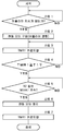
도 3은 주차 브레이크를 작동(어플라이)시킬 때의 도 1 중의 주차 브레이크 제어 장치에 의한 제어 처리를 나타내는 흐름도이다.
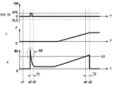
도 4는 주차 브레이크의 작동시의 주차 브레이크 스위치, 회전 직동 변환 기구의 추력, 전동 액추에이터의 전류의 시간 변화의 일례를 나타내는 특성선도이다.
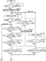
도 5는 주차 브레이크를 해제(릴리스)할 때의 도 1 중의 주차 브레이크 제어 장치에 의한 제어 처리를 나타내는 흐름도이다.
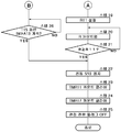
도 6은 도 5에 계속되는 흐름도이다.
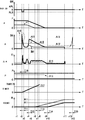
도 7은 주차 브레이크의 해제시의 주차 브레이크 스위치, 회전 직동 변환 기구의 추력, 전동 액추에이터의 전류, 전류 미분값, 액압, 타이머, 회전량의 시간 변화의 일례를 나타내는 특성선도이다.1 is a conceptual diagram of a vehicle equipped with a disc brake device according to an embodiment of the present invention.
It is a longitudinal cross-sectional view which expands and shows the disk brake with electric parking brake provided in the rear wheel side in FIG.
FIG. 3 is a flowchart showing a control process by the parking brake control device in FIG. 1 when the parking brake is operated (applied).
4 is a characteristic line diagram showing an example of a time change of the parking brake switch, the thrust of the rotational linear conversion mechanism, and the current of the electric actuator during the operation of the parking brake.
FIG. 5 is a flowchart illustrating control processing by the parking brake control device in FIG. 1 when releasing (release) the parking brake. FIG.
6 is a flow chart following FIG. 5.
7 is a characteristic diagram showing an example of time variation of the parking brake switch, the thrust of the rotational linear conversion mechanism, the electric current of the electric actuator, the current differential value, the hydraulic pressure, the timer, and the rotation amount when the parking brake is released.
이하, 본 발명의 실시형태에 따른 디스크 브레이크 장치를, 4륜 자동차에 탑재한 경우를 예로 들어, 첨부 도면에 따라서 상세히 설명한다.EMBODIMENT OF THE INVENTION Hereinafter, the case where the disc brake apparatus which concerns on embodiment of this invention is mounted in a four-wheeled motor vehicle is demonstrated in detail according to an accompanying drawing as an example.
도 1에 있어서, 차량의 보디를 구성하는 차체(1)의 하측(노면측)에는, 예컨대 좌, 우의 전륜(2)(FL, FR)과 좌, 우의 후륜(3)(RL, RR)이 설치되어 있다. 이러한 각 전륜(2) 및 각 후륜(3)에는, 각각 일체로 회전하는 디스크로서의 디스크 로터(4)가 설치되어 있다. 즉, 각 전륜(2)은, 액압식의 디스크 브레이크(5)에 의해 각 디스크 로터(4)가 협지되고, 각 후륜(3)은, 후술하는 전동 주차 브레이크 구비 디스크 브레이크(21)에 의해 각 디스크 로터(4)가 협지된다. 이에 따라, 차륜[각 전륜(2) 및 각 후륜(3)]마다 제동력이 부여된다.In Fig. 1, the left and right front wheels 2 (FL, FR) and the left and right rear wheels 3 (RL, RR) are, for example, below the
차체(1)의 프론트 보드 측에는, 브레이크 페달(6)이 설치되어 있다. 이 브레이크 페달(6)은, 차량의 브레이크 조작시에 운전자가 밟는다. 브레이크 페달(6)에는, 페달 스위치(6A)가 설치되어 있다. 이 페달 스위치(6A)는, 브레이크 페달(6)의 밟음 조작을 검출하고, 그 검출 신호를 후술하는 컨트롤 유닛(13)에 출력한다.On the front board side of the
브레이크 페달(6)의 밟음 조작은, 배력(倍力) 장치(7)를 통해 마스터 실린더(8)에 전달된다. 배력 장치(7)는, 브레이크 페달(6)과 마스터 실린더(8)와의 사이에 설치된 부압(負壓) 부스터나 전동 부스터 등으로 이루어지고, 브레이크 페달(6)의 밟음 조작시에 밟는 힘을 증배하여 마스터 실린더(8)에 전달한다. 이때, 마스터 실린더(8)는, 마스터 리저버(9)로부터 공급되는 브레이크액에 의해 액압을 발생시킨다. 마스터 리저버(9)는, 브레이크액이 수용된 작동액 탱크를 구성하고 있다. 또한, 브레이크 페달(6)에 의해 액압을 발생하는 기구는, 상기한 것에 한정되지 않고, 브레이크 바이 와이어 방식의 기구 등, 브레이크 페달(6)의 조작에 따라서 액압을 발생하는 기구이면 좋다.The stepping operation of the
마스터 실린더(8)에 발생한 액압은, 예컨대 한 쌍의 실린더측 액압 배관(10A, 10B)을 통해 액압 공급 장치(11)[이하, ESC(11)라 함]에 보내진다. 이 ESC(11)는, 마스터 실린더(8)로부터의 액압을 브레이크측 배관부(12A, 12B, 12C, 12D)를 통해 각 디스크 브레이크(5, 21)에 분배, 공급한다. 이에 따라, 전술한 바와 같이 차륜[각 전륜(2), 각 후륜(3)]마다 제동력이 부여된다.The hydraulic pressure generated in the
ESC(11)는, ESC(11)를 작동 제어하는 액압 공급 장치용 컨트롤러(13)[이하, 컨트롤 유닛(13)이라 함]를 갖는다. 이 컨트롤 유닛(13)은, ESC(11)를 구동 제어함으로써, 브레이크측 배관부(12A∼12D)로부터 각 디스크 브레이크(5, 21)에 공급하는 브레이크 액압을 증압, 감압 또는 유지하는 제어를 행한다. 이에 따라, 예컨대 배력 제어, 제동력 분배 제어, 브레이크 어시스트 제어, 안티 스키드 제어, 트랙션 제어, 사이드 슬립 방지를 포함하는 차량 안정화 제어, 언덕길 발진 보조 제어 등의 브레이크 제어가 실행된다.The ESC 11 has a controller 13 (hereinafter referred to as a control unit 13) for a hydraulic pressure supply device that operates and controls the
컨트롤 유닛(13)은, 마이크로컴퓨터 등에 의해 구성되고, 배터리(14)로부터의 전력이 전원 라인(15)을 통하여 급전된다. 또한, 컨트롤 유닛(13)은, 도 1에 나타낸 바와 같이, 입력측이 차량 데이터 버스(16) 등에 접속되고, 출력측은 ESC(11)에 전원 라인(15)과 차량 데이터 버스(16)를 통해 접속되어 있다. 또한, ESC(11) 대신에, 공지 기술인 ABS 유닛을 이용해도 좋다. 나아가서는, ESC(11)를 설치하지 않고(생략하고), 마스터 실린더(8)로부터 직접 브레이크측 배관부(12A∼12D)에 접속하는 구성으로 해도 좋다.The
차량 데이터 버스(16)는, 차체(1)에 탑재된 시리얼 통신부로서의 CAN을 포함하여 구성되고, 차량에 탑재된 다수의 전자 기기, 컨트롤 유닛(13) 및 후술하는 주차 브레이크 제어 장치(19) 등과의 사이에서 차량내 다중 통신을 행하는 것이다. 이 경우, 차량 데이터 버스(16)에 보내지는 차량 운전 정보로서는, 예컨대 조타각 센서, 액셀러레이터 센서, 브레이크 센서, 차륜속 센서, 차속 센서, 경사 센서, 스테레오 카메라, 밀리파 레이더, 시트 벨트 센서, 트랜스미션 데이터 등(모두 도시하지 않음)으로부터의 검출 신호 등의 정보, 더 나아가서는 압력 센서(17) 등으로부터의 검출 신호(정보)를 들 수 있다.The
압력 센서(17)는, 브레이크측 배관부(12A, 12B, 12C, 12D)에 각각 설치되고, 각각의 배관내 압력(액압), 바꾸어 말하면 상기 배관내 압력에 대응하는 후술하는 캘리퍼(24)[실린더부(26)] 내의 액압(P)을 개별적으로 검출하는 것이다. 또한, 압력 센서(17)는, 1개 또는 2개 설치하는 구성으로 해도 좋고, 예컨대 마스터 실린더(8)로부터의 실린더측 액압 배관(10A, 10B)에만 설치하는 구성으로 해도 좋다.The
차체(1)에는, 운전석(도시하지 않음)의 근방에 위치하여 주차 브레이크 스위치(18)가 설치되고, 이 주차 브레이크 스위치(18)는 운전자에 의해서 조작된다. 주차 브레이크 스위치(18)가 조작되었을 때에는, 후술하는 주차 브레이크 제어 장치(19)로부터 후륜(3)측의 디스크 브레이크(21)[즉, 후술하는 전동 액추에이터(33)]에 제어 신호가 출력(전력이 급전)되며, 이에 따라 후륜(3)측의 디스크 브레이크(21)는 주차 브레이크로서 작동한다. 또한, 주차 브레이크로서의 작동을 해제할 때에는, 주차 브레이크 스위치(18)가 제동 해제 측으로 조작되고, 이 조작에 수반하여 디스크 브레이크(21)에 전동 액추에이터(33)를 역회전시키는 제어 신호가 출력(전력이 급전)된다.The
또한, 주차 브레이크의 작동은, 차속이 0 km/h인 상태가 소정 시간 계속되었을 때 등, 주차 브레이크 제어 장치(19)에서의 주차 브레이크의 작동 판단 로직에 의해 작동시켜도 좋다. 또한, 주차 브레이크의 해제는, 액셀러레이터 조작 등에 기초하여, 주차 브레이크 제어 장치(19)에서의 주차 브레이크의 해제 판단 로직에 의해 해제시켜도 좋다.In addition, the operation of the parking brake may be operated by the operation determination logic of the parking brake in the parking
주차 브레이크 제어 장치(19)는, 마이크로컴퓨터 등에 의해 구성되고, 배터리(14)로부터의 전력이 전원 라인(15)을 통하여 급전된다. 주차 브레이크 제어 장치(19)는, 본 발명의 구성 요건인 제어 수단을 구성하는 것으로, 후술하는 디스크 브레이크(21)[즉, 전동 액추에이터(33)]의 구동을 제어하고, 차량의 주차, 정차시 등에 제동력을 발생시키는 것이다. 주차 브레이크 제어 장치(19)는, 도 1 및 도 2에 나타낸 바와 같이, 입력측이 주차 브레이크 스위치(18) 등에 접속되고, 출력측은 디스크 브레이크(21)의 전동 액추에이터(33) 등에 접속되어 있다. 또한, 주차 브레이크 제어 장치(19)는, 그 입, 출력측이 차량 데이터 버스(16)를 통해 ESC(11)의 컨트롤 유닛(13) 등에 접속되어 있다.The parking
주차 브레이크 제어 장치(19)는, 예컨대 플래시 메모리, ROM, RAM 등으로 이루어지는 기억부(도시하지 않음)를 갖고, 이 기억부에는, 후술하는 도 3에 나타내는 처리 프로그램, 즉 주차 브레이크를 작동(어플라이)시킬 때의 제어 처리에 이용하는 처리 프로그램, 도 5 및 도 6에 나타내는 처리 프로그램, 즉 주차 브레이크를 해제(릴리스)할 때의 제어 처리에 이용하는 처리 프로그램, 전술한 주차 브레이크의 작동·해제 판단 로직의 프로그램 등이 저장되어 있다.The parking
주차 브레이크 제어 장치(19)는, 차량의 운전자가 주차 브레이크 스위치(18)를 조작했을 때에, 이 주차 브레이크 스위치(18)로부터 출력되는 신호(ON, OFF 신호)에 기초하여 후술하는 전동 액추에이터(33)를 구동하고, 디스크 브레이크(21)를 주차 브레이크로서 작동 내지 작동 해제시키는 것이다. 주차 브레이크 제어 장치(19)에는, 전원 라인(15)의 전압을 검출하는 전압 센서, 각 전동 액추에이터(33)의 전류 및 단자간 전압을 검출하는 전류 센서 및 전압 센서(모두 도시하지 않음)가 내장되어 있다. 이에 따라, 주차 브레이크 제어 장치(19)는, 주차 브레이크를 해제(릴리스)할 때, 즉 후술하는 피스톤 유지 기구[직동 부재(32)와 나사 부재(31)]에 의한 피스톤(29)의 유지를 해제할 때에, 전동 액추에이터(33)의 전류값에 기초하여 해당 전동 액추에이터(33)의 구동을 정지할 수 있도록 구성하고 있다.The parking
또한, 주차 브레이크 제어 장치(19)는, 피스톤 유지 기구에 의한 피스톤(29)의 유지를 해제할 때에, 압력 센서(17)에 의해 캘리퍼(24) 내의 액압(P)을 검출한다. 그리고, 주차 브레이크 제어 장치(19)는, 피스톤(29)의 유지를 해제할 때에, 액압(P)이 소정값 P11 이상으로 높은 경우에는, 피스톤(29)의 유지의 해제가 지시되어 전동 액추에이터(33)가 구동하고 나서 소정 시간 T17 후에, 해당 전동 액추에이터(33)의 구동을 정지하도록 하고 있다. 한편, 액압(P)이 소정값 P11 미만인 경우에는, 전동 액추에이터(33)의 전류값 IM에 기초하여 해당 전동 액추에이터(33)의 구동을 정지하도록 하고 있다. 이러한 전동 액추에이터(33)의 구동을 정지하는 제어에 관해서는, 뒤에서 상세히 설명한다.In addition, the parking
다음으로, 후륜(3)측에 설치되는 전동 주차 브레이크 구비 디스크 브레이크(21)의 구성에 관해서, 도 2를 참조하면서 설명한다.Next, the structure of the
즉, 주차 브레이크 제어 장치(19)와 함께 본 실시형태의 디스크 브레이크 장치를 구성하는 디스크 브레이크(21)는, 전동식의 주차 브레이크가 부설(付設)된 액압식의 디스크 브레이크로서 구성되어 있다. 디스크 브레이크(21)는, 차량의 후륜측의 비회전 부분에 부착되는 부착 부재(22)와, 이너측, 아우터측의 브레이크 패드(23)와, 후술하는 전동 액추에이터(33)가 마련된 캘리퍼(24)를 포함하여 구성되어 있다.That is, the
부착 부재(22)는, 디스크 로터(4)의 외주를 걸치도록 디스크 로터(4)의 축방향(즉, 디스크 축방향)으로 연장되며 디스크 둘레 방향으로 서로 이격된 한 쌍의 아암부(도시하지 않음)와, 상기 각 아암부의 기단 측을 일체적으로 연결하도록 마련되고, 디스크 로터(4)의 이너측이 되는 위치에서 차량의 비회전 부분에 고정되는 두꺼운 지지부(22A)를 포함하여 구성되어 있다. 또한, 부착 부재(22)에는, 디스크 로터(4)의 아우터측이 되는 위치에서 상기 각 아암부의 선단 측을 서로 연결하는 보강 빔(22B)이 일체로 형성되어 있다.The
이에 의해, 부착 부재(22)의 각 아암부끼리는, 디스크 로터(4)의 이너측에서 지지부(22A)에 의해 일체적으로 연결되고, 아우터측에서 보강 빔(22B)에 의해 일체적으로 연결되어 있다. 이너측, 아우터측의 브레이크 패드(23)는, 디스크 로터(4)의 양면에 배치되고, 부착 부재(22)의 상기 각 아암부에 의해 디스크 축방향으로 이동 가능하게 지지되어 있다. 이너측, 아우터측의 브레이크 패드(23)는, 후술하는 캘리퍼(24)[캘리퍼 본체(25), 피스톤(29)]에 의해 디스크 로터(4)의 양면 측에 압박되는 것이다.Thereby, each arm part of the
부착 부재(22)에는, 디스크 로터(4)의 외주측을 걸치도록 캘리퍼(24)가 배치되어 있다. 이 캘리퍼(24)는, 부착 부재(22)의 상기 각 아암부에 대하여 디스크 로터(4)의 축방향을 따라서 이동 가능하게 지지된 캘리퍼 본체(25)와, 이 캘리퍼 본체(25) 내에 설치된 후술하는 피스톤(29) 및 회전 직동 변환 기구(30)와, 전동 액추에이터(33) 등을 포함하여 구성되어 있다.A
캘리퍼 본체(25)는, 실린더부(26)와 브리지부(27)와 클로부(28)에 의해 구성되어 있다. 실린더부(26)는, 축방향의 일측이 격벽부(26A)로 되어 폐색되며 디스크 로터(4)에 대향하는 타측이 개구단으로 된 바닥이 있는 원통형으로 형성되어 있다. 브리지부(27)는, 디스크 로터(4)의 외주측을 걸치도록 상기 실린더부(26)로부터 디스크 축방향으로 연장되어 형성되어 있다. 클로부(28)는, 브리지부(27)를 사이에 두고 실린더부(26)의 반대측에 연장되도록 배치되어 있다. 캘리퍼 본체(25)의 실린더부(26)는, 디스크 로터(4)의 일측(이너측)에 마련된 이너 레그부를 구성하고, 클로부(28)는 디스크 로터(4)의 타측(아우터측)에 마련된 아우터 레그부를 구성하는 것이다.The caliper
캘리퍼 본체(25)의 실린더부(26)는, 본 발명의 구성 요건인 액압 실린더를 구성하고, 도 1에 나타내는 브레이크측 배관부(12C 또는 12D)를 통해 브레이크 페달(6)의 밟음 조작 등에 수반되는 액압이 공급된다. 이 실린더부(26)에는, 후술하는 전동 액추에이터(33)와의 사이에 위치하여 격벽부(26A)가 일체 형성되어 있다. 이 격벽부(26A)의 내주측에는, 전동 액추에이터(33)의 출력축(33B)이 회전 가능하게 장입(裝入)되어 있다. 캘리퍼 본체(25)의 실린더부(26) 내에는, 피스톤(29)과 후술하는 회전 직동 변환 기구(30) 등이 마련되어 있다.The
여기서, 피스톤(29)은, 개구측이 되는 축방향의 일측이 실린더부(26) 내에 삽입되고, 이너측의 브레이크 패드(23)에 대면하는 축방향의 타측이 덮개부(29A)로 되어 폐색되어 있다. 또한, 실린더부(26) 내에는, 회전 직동 변환 기구(30)가 피스톤(29)의 내부에 수용되어 설치되고, 피스톤(29)은, 상기 회전 직동 변환 기구(30)에 의해 실린더부(26)의 축방향으로 추진되도록 되어 있다. 회전 직동 변환 기구(30)는, 본 발명의 구성 요건인 피스톤 추진 기구를 구성하고, 실린더부(26) 내로의 상기 액압 부가와는 다르게 피스톤(29)을 외력[전동 액추에이터(33)]에 의해 추진시키는 것이다.Here, one side of the
회전 직동 변환 기구(30)는, 사다리꼴 나사 등의 수나사가 형성된 막대 형상체로 이루어지는 나사 부재(31)와, 사다리꼴 나사로 이루어지는 암나사 구멍이 내주측에 형성된 추진 부재로서의 직동 부재(32)에 의해 구성되어 있다. 즉, 직동 부재(32)의 내주측에 나사 결합된 나사 부재(31)는, 후술하는 전동 액추에이터(33)에 의한 회전 운동을 직동 부재(32)의 직선 운동으로 변환하는 나사 기구를 구성하고 있다. 이 경우, 직동 부재(32)의 암나사와 나사 부재(31)의 수나사는, 비가역성이 큰 나사, 본 실시형태에 있어서는, 사다리꼴 나사를 이용하여 형성함으로써 피스톤 유지 기구를 구성하고 있다. 이 피스톤 유지 기구는, 전동 액추에이터(33)에 대한 급전을 정지한 상태라도, 직동 부재(32)[즉, 피스톤(29)]를 임의의 위치에서 마찰력(유지력)에 의해 유지하고, 에너지 절약화를 도모할 수 있다. 또한, 피스톤 유지 기구는, 추진한 피스톤을 유지할 수 있으면 좋고, 예컨대 사다리꼴 나사 이외의 비가역성이 큰 나사로 해도 좋다.The rotation linear
직동 부재(32)의 내주측에 나사 결합되어 설치된 나사 부재(31)는, 축방향의 일측에 대직경의 플랜지부가 되는 플랜지부(31A)가 마련되고, 축방향의 타측이 피스톤(29)의 덮개부(29A)측을 향하여 연장되어 있다. 나사 부재(31)는, 플랜지부(31A) 측에서 후술하는 전동 액추에이터(33)의 출력축(33B)에 일체적으로 연결되어 있다. 또한, 직동 부재(32)의 외주측에는, 직동 부재(32)를 피스톤(29)에 대하여 회전 방지(상대 회전을 규제)하고, 축방향의 상대 이동을 허용하는 결합 돌출부(32A)가 마련되어 있다.As for the
전동 모터로서의 전동 액추에이터(33)는, 케이싱(33A) 내에 설치되어 있다. 이 케이싱(33A)은, 캘리퍼 본체(25)의 실린더부(26)에 격벽부(26A)의 외측 위치에서 고정하여 설치되어 있다. 전동 액추에이터(33)는, 스테이터, 로터 등을 내장하는 공지 기술의 전동 모터와, 이 전동 모터의 토크를 증폭하는 감속기(모두 도시하지 않음)로 구성되어 있다. 감속기는, 증폭 후의 회전 토크를 출력하는 출력축(33B)을 갖는다. 출력축(33B)은, 실린더부(26)의 격벽부(26A)를 축방향으로 관통하여 연장되고, 실린더부(26) 내에서 나사 부재(31)의 플랜지부(31A)측과 일체로 회전하도록 연결되어 있다.The
출력축(33B)과 나사 부재(31)와의 연결 수단은, 예컨대 축방향으로는 이동 가능하지만 회전 방향으로는 회전 방지되도록 되어 있고, 예컨대 스플라인 감합(嵌合)이나 다각형 기둥에 의한 감합(비원형 감합) 등의 공지의 기술이 이용된다. 또한, 감속기로서는, 예컨대 유성 기어 감속기나 웜 기어 감속기 등을 이용해도 좋다.The connecting means between the
그런데, 전동 액추에이터(33)의 제조 비용을 저감하기 위해서는, 부품의 제조 정밀도(가공 정밀도, 조립 정밀도 등)를 낮추는 것이 효과적이다. 그러나, 제조 정밀도를 낮춘 경우, 감속기의 백 래쉬나, 플랜지부(31A)와 출력축(33B)의 덜거덕거림 등에 기인한, 전동 액추에이터(33)와 회전 직동 변환 기구(30)의 회전 방향 덜거덕거림이 증대될 가능성이 있다. 나아가서는, 제조에 수반된 편차(개체차)에 의해, 회전 방향 덜거덕거림이 작아지거나 커지거나 할 가능성도 있다. 그러나, 후술하는 본 실시형태에 따른 전동 액추에이터(33)의 제어 방법에 따르면, 이러한 회전 방향 덜거덕거림에 상관없이, 정밀도 좋게 주차 브레이크의 해제 동작을 행할 수 있다.By the way, in order to reduce the manufacturing cost of the
여기서, 운전자가 도 1 및 도 2에 나타내는 주차 브레이크 스위치(18)를 조작했을 때에는, 주차 브레이크 제어 장치(19)를 통하여 전원 라인(15)으로부터 전동 액추에이터(33)에 급전이 행해지고, 전동 액추에이터(33)의 출력축(33B)이 회전된다. 이 때문에, 회전 직동 변환 기구(30)의 나사 부재(31)는, 예컨대 한 방향으로 출력축(33B)과 일체로 회전되고, 직동 부재(32)를 통해 피스톤(29)을 디스크 로터(4) 측으로 추진(구동)한다. 이에 따라, 디스크 브레이크(21)는, 디스크 로터(4)를 이너측, 아우터측의 브레이크 패드(23) 사이에서 협지하고, 전동식의 주차 브레이크로서 작동(어플라이)된다.Here, when the driver operates the
한편, 주차 브레이크 스위치(18)가 제동 해제 측으로 조작되었을 때에는, 전동 액추에이터(33)에 의해 회전 직동 변환 기구(30)의 나사 부재(31)가 다른 방향(역방향)으로 회전 구동된다. 이에 따라, 직동 부재(32)가 회전 직동 변환 기구(30)를 통해 디스크 로터(4)로부터 떨어지는(이격되는) 후퇴 방향으로 구동되고, 디스크 브레이크(21)는 주차 브레이크로서의 작동이 해제(릴리스)된다.On the other hand, when the
이 경우, 회전 직동 변환 기구(30)에서는, 나사 부재(31)가 직동 부재(32)에 대하여 상대 회전되면, 피스톤(29) 내에서의 직동 부재(32)의 회전이 규제되어 있기 때문에, 직동 부재(32)는, 나사 부재(31)의 회전 각도에 따라서 축방향으로 상대 이동한다. 이에 따라, 회전 직동 변환 기구(30)는, 회전 운동을 직선 운동으로 변환한다. 또한, 본 실시형태에 있어서는, 회전 직동 변환 기구(30)를 나사 기구에 의해 구성했지만, 이외의 회전 직동 변환 기구, 예컨대 볼 나사 기구, 볼 램프 기구, 롤러 램프 기구 또는 정밀 롤러 나사 기구 등을 이용해도 좋다. 또한, 본 실시형태에 있어서는, 회전 직동 변환 기구(30)가 피스톤(29) 내에 수용되도록 구성되어 있지만, 회전 직동 변환 기구(30)에 의해 피스톤(29)이 추진되도록 되어 있으면, 반드시 회전 직동 변환 기구(30)가 피스톤(29) 내에 수용되어 있지 않아도 좋다.In this case, in the rotation-
실린더부(26)의 격벽부(26A)에는, 나사 부재(31)의 플랜지부(31A)와의 사이에 스러스트 베어링(34)이 설치되어 있다. 이 스러스트 베어링(34)은, 나사 부재(31)로부터의 스러스트 하중을 격벽부(26A)와 함께 받고, 격벽부(26A)에 대한 나사 부재(31)의 회전을 원활하게 하는 것이다. 또한, 실린더부(26)의 격벽부(26A)에는, 전동 액추에이터(33)의 출력축(33B)과의 사이에 시일 부재(35)가 설치되고, 이 시일 부재(35)는, 실린더부(26) 내의 브레이크액이 전동 액추에이터(33) 측으로 누설되는 것을 저지하도록 양자의 사이를 시일하고 있다.A
또한, 실린더부(26)의 개구단 측에는, 이 실린더부(26)와 피스톤(29)과의 사이를 시일하는 탄성 시일로서의 피스톤 시일(36)과, 실린더부(26) 내로의 이물 침입을 막는 더스트 부츠(37)가 설치되어 있다. 더스트 부츠(37)는, 가요성을 갖는 주름상자형의 시일 부재에 의해 구성되고, 실린더부(26)의 개구단과 피스톤(29)의 덮개부(29A)측의 외주와의 사이에 부착되어 있다.Moreover, on the open end side of the
또한, 전륜(2)측의 디스크 브레이크(5)는, 후륜(3)측의 디스크 브레이크(21)와 주차 브레이크 기구를 제외하면 거의 동일하게 구성되어 있다. 즉, 전륜(2)측의 디스크 브레이크(5)는, 후륜(3)측의 디스크 브레이크(21)와 같이, 주차 브레이크로서 작동하는 회전 직동 변환 기구(30)[나사 부재(31) 및 직동 부재(32)] 및 전동 액추에이터(33) 등이 설치되어 있지는 않다. 그러나, 이외의 점에서는 전륜(2)측의 디스크 브레이크(5)도 디스크 브레이크(21)와 거의 동일하게 구성되는 것이다. 또한, 경우에 따라서는 디스크 브레이크(5) 대신에, 전륜(2)측에도 전동 주차 브레이크 구비 디스크 브레이크(21)를 설치하는 구성으로 해도 좋다.In addition, the
또한, 본 발명에 적용하는 디스크 브레이크(21)는, 전동의 회전 모터에 의한 주차 브레이크가 부설된 액압식의 디스크 브레이크 장치이면, 그 구성은, 상기 실시형태의 구성이 아니라도 좋다.In addition, if the
본 실시형태에 따른 4륜 자동차의 디스크 브레이크 장치는, 전술한 바와 같은 구성을 갖는 것으로, 다음에, 그 작동에 관해서 설명한다.The disc brake device for a four-wheeled vehicle according to the present embodiment has the configuration as described above. Next, the operation thereof will be described.
차량의 운전자가 브레이크 페달(6)을 밟음 조작하면, 그 밟는 힘이 배력 장치(7)를 통해 마스터 실린더(8)에 전달되고, 마스터 실린더(8)에 의해 브레이크 액압이 발생한다. 마스터 실린더(8)에서 발생한 액압은, 실린더측 액압 배관(10A, 10B), ESC(11) 및 브레이크측 배관부(12A, 12B, 12C, 12D)를 통해 각 디스크 브레이크(5, 21)에 분배, 공급되고, 좌, 우의 전륜(2)과 좌, 우의 후륜(3)에 각각 제동력이 부여된다.When the driver of the vehicle depresses the
이 경우, 후륜(3)측의 디스크 브레이크(21)에 관해서 설명하면, 캘리퍼(24)의 실린더부(26) 내에 브레이크측 배관부(12C, 12D)를 통해 액압이 공급되고, 실린더부(26) 내의 액압 상승에 따라서 피스톤(29)이 이너측의 브레이크 패드(23)를 향해 미끄럼 이동 변위된다. 이에 따라, 피스톤(29)은, 이너측의 브레이크 패드(23)를 디스크 로터(4)의 일측면에 압박하고, 이때의 반력에 의해서 캘리퍼(24) 전체가 부착 부재(22)의 상기 각 아암부에 대하여 디스크 로터(4)의 이너측으로 미끄럼 이동 변위한다.In this case, the
그 결과, 캘리퍼(24)의 아우터 레그부[클로부(28)]는, 아우터측의 브레이크 패드(23)를 디스크 로터(4)에 압박하도록 동작하고, 디스크 로터(4)는, 한 쌍의 브레이크 패드(23)에 의해 축방향의 양측으로부터 협지되며, 액압 부여에 따른 제동력이 발생된다. 한편, 브레이크 조작을 해제했을 때에는, 실린더부(26) 내로의 액압 공급이 해제, 정지됨으로써, 피스톤(29)이 실린더부(26) 내로 후퇴하도록 변위되고, 이너측과 아우터측의 브레이크 패드(23)가 디스크 로터(4)로부터 이격됨으로써, 차량은 비제동 상태로 되돌아간다.As a result, the outer leg portion (claw portion 28) of the
다음으로, 차량의 운전자가 주차 브레이크를 작동시키도록 주차 브레이크 스위치(18)를 조작했을 때에는, 주차 브레이크 제어 장치(19)로부터 디스크 브레이크(21)의 전동 액추에이터(33)에 급전이 행해지고, 전동 액추에이터(33)의 출력축(33B)이 회전 구동된다. 전동 주차 브레이크 구비 디스크 브레이크(21)는, 전동 액추에이터(33)의 회전을 회전 직동 변환 기구(30)의 나사 부재(31)와 직동 부재(32)를 통해 직선 운동으로 변환하고, 직동 부재(32)를 축방향으로 이동시켜 피스톤(29)을 추진함으로써, 한 쌍의 브레이크 패드(23)를 디스크 로터(4)의 양면에 압박한다.Next, when the driver of the vehicle operates the
이때, 직동 부재(32)는, 나사 부재(31)와의 사이에 발생하는 마찰력(유지력)에 의해 제동 상태로 유지되고, 후륜(3)측의 디스크 브레이크(21)는 주차 브레이크로서 작동된다. 즉, 전동 액추에이터(33)에의 급전을 정지한 후에도, 직동 부재(32)의 암나사와 나사 부재(31)의 수나사로 이루어지는 피스톤 유지 기구에 의해, 직동 부재(32)[즉, 피스톤(29)]를 제동 위치에 유지할 수 있다.At this time, the
한편, 운전자가 주차 브레이크를 해제하도록 주차 브레이크 스위치(18)를 제동 해제 측으로 조작했을 때에는, 주차 브레이크 제어 장치(19)로부터 전동 액추에이터(33)에 대하여 모터 역회전용의 급전이 행해지고, 전동 액추에이터(33)의 출력축(33B)은, 주차 브레이크의 작동시와 역방향으로 회전된다. 이때, 회전 직동 변환 기구(30)는, 나사 부재(31)와 직동 부재(32)에 의한 제동력의 유지가 해제되고, 전동 액추에이터(33)의 역회전에 대응한 이동량으로 직동 부재(32)를 실린더부(26) 내로 복귀 방향으로 이동시키며, 주차 브레이크[디스크 브레이크(21)]의 제동력을 해제한다.On the other hand, when the driver operates the
그런데, 디스크 브레이크(21)를 주차 브레이크로서 작동시킬 때나 그 작동을 해제할 때에, 전동 액추에이터(33)의 구동의 정지를, 해당 전동 액추에이터(33)의 전류값에 따라서 행하는 것이 고려된다. 다만, 이러한 구성의 경우, 예컨대 주차 브레이크의 작동을 해제할 때에, 그때의 캘리퍼(24)[실린더부(26)] 내의 액압의 크기에 따라서는, 전동 액추에이터(33)가 과도하게 회전하고, 피스톤(29)을 압박하는 부재인 직동 부재(32)가 디스크 로터(4)로부터 크게 후퇴할 우려가 있다. 이 경우, 다음에 주차 브레이크를 작동시킬 때에, 직동 부재(32)의 이동량이 증가하고, 응답성이 저하될(주차 브레이크의 작동 완료까지의 시간이 길어질) 우려가 있다.By the way, when the
따라서, 본 실시형태에서는, 주차 브레이크의 작동을 해제할 때에, 전동 액추에이터(33)의 구동의 정지를, 해당 전동 액추에이터(33)의 전류값 IM과 그때의 액압(P)에 따라서 판정하는 구성으로 하고 있다. 이하, 주차 브레이크를 작동(어플라이)시킬 때와, 주차 브레이크를 해제(릴리스)할 때에, 주차 브레이크 제어 장치(19)에서 행하는 제어 처리에 관해서, 도 3 및 도 5, 도 6을 참조하면서 설명한다. 또한, 이하의 설명은, 주차 브레이크를 거는, 즉 브레이크 패드(23)에 소정의 압박력을 부여하여, 그때의 피스톤 위치를 유지하기 위한 동작을 「어플라이」라고 하고, 주차 브레이크를 해제, 즉 그 유지를 해제하기 위한 동작을 「릴리스」라고 한다.Therefore, in this embodiment, when canceling the operation of the parking brake, the stop of driving of the
우선, 어플라이 시에 주차 브레이크 제어 장치(19)에서 행하는 제어 처리에 관해서, 도 3을 이용하여 설명한다.First, the control process performed by the parking
도 3의 처리 동작이 시작되면, 스텝 1에서는, 주차 브레이크 스위치(18)나 주차 브레이크의 작동 판단 로직에 의해 어플라이 지시가 있는지 여부를 판정한다. 이 스텝 1에서, 「NO」, 즉 어플라이 지시가 없다고 판정된 경우는, 다시 스텝 1로 되돌아간다. 한편, 스텝 1에서, 「YES」, 즉 어플라이 지시가 있다고 판정된 경우에는, 스텝 2로 진행한다.When the processing operation of FIG. 3 starts, in
스텝 2에서는, 스텝 1에서의 「YES」의 판정에 기초하여, 주차 브레이크 제어 장치(19)는, 직동 부재(32)[피스톤(29)]가 디스크 로터(4)에 접근하는 방향으로 전동 액추에이터(33)를 구동한다. 다음에, 스텝 3에서는, 타이머 TMR1을 카운트업한다. 다음에, 스텝 4에서는, 타이머 TMR1에 의해, 카운트업 개시, 즉 전동 액추에이터(33)를 구동하고 나서 소정 시간 T1을 경과했는지(타이머 TMR1이 소정 시간 T1 이상인지) 아닌지를 판정한다.In
스텝 4에서, 「NO」, 즉 소정 시간 T1에 달하고 있지 않다고(TMR1<T1) 판정된 경우는, 스텝 2와 스텝 3과의 사이에 되돌아가고, 스텝 3에서, 타이머 TMR1을 카운트업한다. 한편, 스텝 4에서, 「YES」, 즉 소정 시간 T1에 달했다고(TMR1≥T1) 판정된 경우는, 스텝 5에 진행한다. 여기서, 소정 시간 T1은, 전동 액추에이터(33)에의 통전 직후에 발생하는 돌입 전류(도 4의 A0 참조)가, 소정값 A1 미만이 되기까지의 시간보다 길게 되도록 설정되어 있다.In
다음으로, 스텝 5에서는, 피스톤(29)이 제동 위치에 달했는지 여부를 판정한다. 이 때문에, 스텝 5에서는, 전동 액추에이터(33)의 전류값 IM이, 소정 시간 T2의 동안, 소정값 A1 이상(IM≥A1)을 계속했는지 여부를 판정한다. 스텝 5에서, 「NO」, 즉 전류값 IM이 소정 시간 T2의 동안, 소정값 A1 이상을 계속하고 있지 않다고 판정된 경우는, 다시 스텝 5로 되돌아간다. 한편, 스텝 5에서, 「YES」, 즉 전류값 IM이 소정 시간 T2의 동안, 소정값 A1 이상을 계속했다고 판정된 경우는, 스텝 6으로 진행한다.Next, in
스텝 6에서는, 전동 액추에이터(33)에의 통전을 정지한다. 이에 따라, 회전 직동 변환 기구(30)의 작동이 완료되어, 피스톤(29)이 제동 위치에 유지된다. 그리고, 계속되는 스텝 7에서, 타이머 TMR1을 클리어하고, 주차 브레이크 제어 장치(19)에서 어플라이 시에 행해지는 제어 처리가 종료된다.In
다음으로, 어플라이 시의 주차 브레이크 스위치(18)의 조작(SW), 회전 직동 변환 기구(30)에서 발생하는[전동 액추에이터(33)에 의해 생긴) 추력 F, 전동 액추에이터(33)의 전류 IM의 시간 변화를, 도 4를 참조하면서 설명한다.Next, the operation (SW) of the
시간축의 a1 시점에서는, 주차 브레이크 스위치(18)에 의한 어플라이 지시(APL)는 이루어져 있지 않고, 전동 액추에이터(33)는 정지해 있으며, 해당 전동 액추에이터(33)의 전류 IM은 0이 된다. 시간축의 a2 시점에서, 주차 브레이크 스위치(18)에 의한 어플라이 지시가 이루어지면(스텝 1에서 「YES」라고 판정됨), 주차 브레이크 제어 장치(19)는, 전동 액추에이터(33)를 직동 부재(32)[피스톤(29)]가 디스크 로터(4)에 접근하는 방향으로 시동(통전)한다(스텝 2). 이때(통전 직후), 정지 상태로부터 구동 상태로 이행되기 때문에, 전동 액추에이터(33)에는, 한번 큰 돌입 전류(A0)가 발생한 후, 전동 액추에이터(33)는 구동 상태로 되고, 해당 전동 액추에이터(33)의 전류 IM은 점차로 저하된다. 또한, 전동 액추에이터(33)가 구동되는 시간축의 a2 시점으로부터 a3 시점에 이르는 소정 시간 T1의 동안은, 전류 IM이 소정값 A1 이상인지 여부의 판정은 행하지 않는다(스텝 4). 이 스텝 3, 스텝 4에 의해, 돌입 전류에 의한 오판정을 방지한다.At time a1 of the time axis, the application instruction APL by the
소정 시간 T1의 경과 후, 전동 액추에이터(33)의 구동에 의해 회전 직동 변환 기구(30)에서 발생하는 추력 F가 증가하여 브레이크 패드(23)가 디스크 로터(4)에 압박되면, 시간축의 a3 시점으로부터 a4 시점까지의 동안에, 전동 액추에이터(33)의 전류 IM이 점차 상승한다. 그리고, 전동 액추에이터(33)의 전류 IM이 소정 시간 T2의 동안, 소정값 A1 이상을 계속했는지 여부가 판정되고(스텝 5), 전류 IM이 소정 시간 T2의 동안 소정값 A1 이상이 되면, 시간축의 a5 시점에서 전동 액추에이터(33)에의 통전이 정지되며, 어플라이 완료가 된다(스텝 6). 이 소정 시간 T2는, 전류 IM에 중첩하는 리플형의 노이즈에 의해 어플라이 완료와 오판정을 방지하기 위해서 마련되어 있다. 또한, 노이즈 필터를 이용하면, 전류 IM이 소정값 A1 이상인지를 판단하면 좋다. 또한, 소정값 A1은, 주차하는 노면의 경사나 디스크 브레이크(21)[캘리퍼(24)] 내의 액압(P)의 크기에 따라서 보정해도 좋다.After the elapse of the predetermined time T1, when the thrust F generated by the rotational
다음으로, 릴리스 시에 주차 브레이크 제어 장치(19)에서 행하는 제어 처리에 관해서, 도 5 및 도 6을 이용하여 설명한다.Next, the control process performed by the parking
도 5의 처리 동작이 시작되면, 스텝 11에서는, 주차 브레이크 스위치(18)나 주차 브레이크의 해제 판단 로직에 의해 릴리스 지시가 있는지 여부를 판정한다. 이 스텝 11에서, 「NO」, 즉 릴리스 지시가 없다고 판정된 경우는, 다시 스텝 11로 되돌아간다. 한편, 스텝 11에서, 「YES」, 즉 릴리스 지시가 있다고 판정된 경우에는, 스텝 12로 진행한다.When the processing operation of FIG. 5 starts, in
스텝 12에서는, 스텝 11에서의 「YES」의 판정에 기초하여, 주차 브레이크 제어 장치(19)는, 직동 부재(32)[피스톤(29)]가 디스크 로터(4)로부터 이격되는 방향으로 전동 액추에이터(33)를 구동한다. 스텝 12에서, 전동 액추에이터(33)를 구동했다면(구동을 개시했다면), 스텝 12로부터 스텝 13과 스텝 27과 스텝 29로 진행한다. 이 경우, 스텝 13으로부터 계속되는 처리와, 스텝 27로부터 계속되는 처리와, 스텝 29로부터 계속되는 처리는, 병행하여 행한다.In Step 12, based on the determination of "YES" in
여기서, 스텝 13부터 스텝 18은, 전동 액추에이터(전동 모터)(33)의 구동 전류 IM을 모니터하고, 추력 F가 없어지는, 즉 전동 액추에이터(33)에 의해 생긴 추력 F가 해제된 것을 검출하는 스텝이다(전류 판정). 또한, 스텝 29로부터 스텝 31은, 전동 액추에이터(33)의 구동 시간(경과 시간)으로부터, 추력 F가 없어지는, 즉 전동 액추에이터(33)에 의해 생긴 추력 F가 해제된 것을 추정하는 스텝이다(시간 판정). 또한, 스텝 27, 스텝 28은, 릴리스 개시 시의 액압(P)에 의해, 전술한 전류 판정을 이용하는지 시간 판정을 이용하는지를 결정하는 스텝이다.Here,
우선, 스텝 13에서는, 타이머 TMR11을 카운트업한다. 다음에, 스텝 14에서는, 타이머 TMR11에 의해, 카운트업 개시, 즉 전동 액추에이터(33)를 구동하고 나서 소정 시간 T11을 경과했는지(타이머 TMR11이 소정 시간 T11 이상인지) 여부를 판정한다. 스텝 14에서, 「NO」, 즉 소정 시간 T11에 달하고 있지 않다고(TMR11<T11) 판정된 경우는, 스텝 13에 되돌아가고, 타이머 TMR1을 카운트업한다. 이에 따라, 돌입 전류에 의한 전류값 변화를 이후의 전류값의 판단으로부터 배제한다.First, in
한편, 스텝 14에서, 「YES」, 즉 소정 시간 T11에 달했다고(TMR11≥T11) 판정된 경우는, 스텝 14로부터 스텝 15와 스텝 26으로 진행한다. 이 경우, 스텝 15로부터 계속되는 처리와, 스텝 26으로부터 계속되는 처리는, 병행하여 행한다. 또한, 소정 시간 T11은, 전동 액추에이터(33)에의 통전 직후에 발생하는 돌입 전류(도 7의 A10 참조)가, 소정값 A11 미만이 되기까지의 시간보다 길게 되도록 설정되어 있다.On the other hand, when it is determined in
스텝 15에서는, 회전 직동 변환 기구(30)에 가해지는 추력 F, 즉 전동 액추에이터(33)에 의해 생긴 추력 F가 내려가기 시작했는지 여부를, 전류 IM의 변화로 판정한다. 전류 IM은, 추력 F가 내려가기 시작했을 때에 커지기 때문에, 스텝 15에서는, 전동 액추에이터(33)의 전류값 IM이, 소정 시간 T12의 동안, 소정값 A11 이상(IM≥A11)을 계속했는지 여부를 판정함으로써, 추력 F가 내려가기 시작한 것을 판정한다. 스텝 15에서, 「NO」, 즉 전류값 IM이 소정 시간 T12의 동안, 소정값 A11 이상을 계속하지 않는다고 판정된 경우는, 다시 스텝 15로 되돌아간다. 한편, 스텝 15에서, 「YES」, 즉 전류값 IM이 소정 시간 T12의 동안, 소정값 A11이상을 계속했다고 판정된 경우는, 스텝 16으로 진행한다. 여기서, 소정값 A11은 일정 값으로 해도 좋지만, 디스크 브레이크(21)[캘리퍼(24)] 내의 액압(P)과 전원 라인(15)으로부터의 전압 V에 따라서 보정해도 좋다. 여기서는, 액압(P)이 높을수록 소정값 A11을 작게 하고, 전압 V가 낮을수록 소정값 A11을 작게 하도록 설정한다. 또한, 어플라이에서 이용한 소정값 A1로 보정해도 좋고, 소정값 A1이 작을수록 소정값 A11을 작게 한다.In
다음으로, 스텝 16에서는, 그 후(스텝 15에서 「YES」라고 판정된 후) 회전 직동 변환 기구(30)에 가해지는 추력 F[전동 액추에이터(33)에 의해 생긴 추력 F]가 0에 근접해 있는지 여부를, 전류 IM의 변화로 판정한다. 전류 IM은, 추력 F가 0에 근접함에 따라서 작아지기 때문에, 스텝 16에서는, 전동 액추에이터(33)의 전류 IM이, 소정 시간 T13의 동안, 소정값 A12 이하를 계속했는지 여부를 판정함으로써, 추력 F가 0에 근접한 것을 판정한다. 스텝 16에서, 「NO」, 즉 전류값 IM이 소정 시간 T13의 동안, 소정값 A12 이하를 계속하고 있지 않다고 판정된 경우는, 다시 스텝 16으로 되돌아간다. 한편, 스텝 16에서, 「YES」, 즉 전류값 IM이 소정 시간 T13의 동안, 소정값 A12 이하를 계속했다고 판정된 경우는, 스텝 17로 진행한다. 또한, 소정값 A11과 소정값 A12는, 동일한 값으로 해도 좋고 상이한 값으로 해도 좋다. 후술하는 도 7의 특성선도에서는, 소정값 A11과 소정값 A12는 동일한 값으로 하고 있다.Next, in
다음으로, 스텝 17에서는, 그 후(스텝 16에서 「YES」라고 판정된 후) 회전 직동 변환 기구(30)에 가해지는 추력 F[전동 액추에이터(33)에 의해 생긴 추력 F]가 0이 되었는지 여부를, 전류 IM이 거의 일정해졌는지로 판정한다. 이 때문에, 스텝 17에서는, 전동 액추에이터(33)의 전류 미분값 D가, 소정 시간 T14의 동안, 소정값 D11 이하를 계속했는지 여부를 판정한다. 스텝 17에서, 「NO」, 즉 전류 미분값 D가 소정 시간 T14의 동안, 소정값 D11 이하를 계속하고 있지 않다고 판정된 경우는, 다시 스텝 17로 되돌아간다. 한편, 스텝 17에서, 「YES」, 즉 전류 미분값 D가 소정 시간 T14의 동안, 소정값 D11 이하를 계속했다고 판정된 경우는, 스텝 18로 진행한다.Next, in
스텝 18에서는, 후술하는 판정 전환 플래그가 OFF인지 여부를 판정한다. 이 스텝 18에서, 「YES」, 즉 판정 전환 플래그가 OFF라고(후술하는 스텝 27로부터 스텝 28에 진행할 수 없고 판정 전환 플래그가 ON이 되지 않음) 판정된 경우는, 도 6의 스텝 19로 진행한다. 한편, 스텝 18에서, 「NO」, 즉 판정 전환 플래그가 OFF가 아니라고(후술하는 스텝 27에서부터 스텝 28로 진행함으로써 판정 전환 플래그가 ON으로 되어 있음) 판정된 경우는, 다시 스텝 18로 되돌아간다. 이 경우는, 스텝 18로 되돌아가는 처리가 반복되고, 스텝 18에서부터 스텝 19로 진행할 수 없게 되어, 후술하는 스텝 31에서부터 스텝 19로 진행하게 된다.In
한편, 스텝 29에서는, 타이머 TMR17을 카운트업한다. 다음에, 스텝 30에서는, 타이머 TMR17에 의해, 카운트업 개시, 즉 전동 액추에이터(33)를 구동하고 나서 소정 시간 T17을 경과했는지(타이머 TMR17이 소정 시간 T17 이상인지) 여부를 판정한다. 스텝 30에서, 「NO」, 즉 소정 시간 T17에 달하고 있지 않다고(TMR17<T17) 판정된 경우는, 스텝 30으로 되돌아가고, 타이머 TMR17을 카운트업한다. 한편, 스텝 30에서, 「YES」, 즉 소정 시간 T17에 달했다고(TMR17≥T17) 판정된 경우는, 스텝 31로 진행한다.In
여기서, 소정 시간 T17은, 전동 모터[전동 액추에이터(33)]에 의해 생긴 추력 F가 해제된 것을 판단하기 위한 시간이며, 이 소정 시간 T17은, 검출된 액압(P)과 피스톤 유지 기구[직동 부재(32)와 나사 부재(31)]에 의한 피스톤(29)의 유지력과의 관계에 기초하여 설정할 수 있다. 즉, 릴리스의 경우, 액압(P)과 피스톤(29)의 유지력[바꾸어 말하면, 유지력의 반력으로서 회전 직동 변환 기구(30)에 가해지는 추력 F]에 따라서, 직동 부재(32)의 힘(추력 F)이 0이 되는 타이밍이 변화(변동)한다. 그래서, 액압(P)과 피스톤(29)의 유지력에 따라 소정 시간 T17을 설정함으로써, 이 소정 시간 T17을, 그 액압(P)과 피스톤(29)의 유지력에 따른 적절한 값으로 설정할 수 있다.Here, the predetermined time T17 is time for judging that the thrust F generated by the electric motor (electric actuator 33) has been released, and this predetermined time T17 is the detected hydraulic pressure P and the piston holding mechanism (direct member). (32) and the screw member 31] can be set based on the relationship between the holding force of the
예컨대, 소정 시간 T17은, 검출된 액압(P)이 높을수록 짧은 시간으로서 설정할 수 있다. 또한, 피스톤(29)의 유지력이 작을수록 짧은 시간으로서 설정할 수 있다. 즉, 액압(P)이 높을수록, 또는 피스톤(29)의 유지력이 작을수록, 직동 부재(32)의 힘(추력 F)이 0이 되는 타이밍이 빨라진다. 이 때문에, 액압(P)과 피스톤(29)의 유지력에 따라서 소정 시간 T17을 설정함으로써, 직동 부재(32)의 힘(추력 F)이 0이 된 것을 보다 확실하게 판정할 수 있다(보다 정밀도 좋게 추정 내지 검지할 수 있다). 이에 따라, 전동 액추에이터(33)의 구동을 적절한 타이밍으로 정지시키는 것[직동 부재(32)를 디스크 로터(4)로부터 적절히 이격된 원하는 위치에서 정지시키는 것]을 할 수 있다.For example, the predetermined time T17 can be set as a short time as the detected hydraulic pressure P is higher. The smaller the holding force of the
또한, 소정 시간 T17은, 액압(P)과 전원 라인(15)으로부터의 전압 V를 파라미터로 하여 보정하는 것도 바람직하다. 예컨대, 액압(P)이 높을수록 소정 시간 T17을 짧게 하는 한편, 전압 V도 높을수록 소정 시간 T17을 짧게 하도록 설정한다. 또한, 어플라이에서 이용한 소정값 A1에 의해서 보정해도 좋고, 소정값 A1이 작을수록 소정 시간 T17이 짧아지도록 한다.Moreover, it is also preferable to correct | amend the predetermined time T17 by using the hydraulic pressure P and the voltage V from the
다음으로, 스텝 31에서는, 후술하는 판정 전환 플래그가 ON인지 여부를 판정한다. 이 스텝 31에서, 「YES」, 즉 판정 전환 플래그가 ON이라고(후술하는 스텝 27로부터 스텝 28로 진행함으로써 판정 전환 플래그가 ON으로 되어 있음) 판정된 경우는, 도 6의 스텝 19로 진행한다. 한편, 스텝 18에서, 「NO」, 즉 판정 전환 플래그가 ON이 아니라고(후술하는 스텝 27로부터 스텝 28로 진행할 수 없고 판정 전환 플래그가 ON이 되지 않음) 판정된 경우는, 다시 스텝 31로 되돌아간다. 이 경우는, 스텝 31로 되돌아가는 처리가 반복되고, 스텝 31로부터 스텝 19로 진행할 수 없게 되어, 스텝 18로부터 스텝 19로 진행하게 된다.Next, in
그런데, 본 실시형태에 따르면, 회전 직동 변환 기구(30)에 가해지는 추력 F가 0이 되었는지 여부의 판정[전동 액추에이터(33)에 의해 생긴 추력 F가 해제되었는지 여부의 판단]을, 액압(P)의 크기에 따라서 전환하는 구성으로 되어 있다. 즉, 추력 F가 0이 되었는지 여부의 판정을, 스텝 15, 스텝 16, 스텝 17에서의 전류 IM과 전류 미분값 D의 판정에 의해서 행하는지, 또는 스텝 30에서의 소정 시간 T17의 경과 판정에 의해서 행하는지를, 액압(P)의 크기에 따라서 전환하는 구성으로 하고 있다.By the way, according to this embodiment, determination of whether the thrust F applied to the rotational
이 때문에, 스텝 27에서는, 디스크 브레이크(41)에 가해지는 액압(P)이, 소정 시간 T16의 동안, 소정값 P11 이상을 계속했는지 여부를 판정한다. 여기서, 액압(P)은, 예컨대 압력 센서(17)에 의해 검출한다. 또한, 소정값 P11은, 추력 F가 0이 되었는지 여부의 판정을, 전류값 IM에 의한 판정으로 행하는지 소정 시간 T17의 경과에 의한 판정으로 행하는지를 적절히 전환할 수 있는 값으로서 미리 설정해 둔다. 스텝 27에서, 「YES」, 즉 액압(P)이 소정 시간 T16의 동안, 소정값 P11 이상을 계속했다고 판정된 경우는, 스텝 28로 진행한다. 그리고, 스텝 28에서, 판정 전환 플래그가 ON된다.For this reason, in
한편, 스텝 27에서, 「NO」, 즉 액압(P)이 소정 시간 T16의 동안, 소정값 P11 이상을 계속하고 있지 않다고 판정된 경우는, 다시 스텝 27로 되돌아간다. 따라서, 스텝 27에서 「YES」라고 판정되지 않는(「NO」가 계속된) 경우는, 판정 전환 플래그는 초기값인 OFF인 채이고, 이 경우는, 스텝 17에서 「YES」라고 판정된 단계에서, 스텝 18의 조건이 성립하여(스텝 18에서 「YES」라고 판정되어), 이 스텝 18을 통하여 도 6의 스텝 19로 진행한다. 이에 비하여, 스텝 27에서 「YES」라고 판정된 경우는, 계속되는 스텝 28에서 판정 전환 플래그가 ON이 되고, 이 경우는, 스텝 30에서 「YES」라고 판정된 단계에서, 스텝 31의 조건이 성립하여(스텝 31에서 「YES」라고 판정되어), 이 스텝 31을 통하여 도 6의 스텝 19로 진행하게 된다.On the other hand, in
다음으로, 도 6의 스텝 19로부터 스텝 22는, 이전의 스텝에서 전동 액추에이터(33)의 추력 F가 없어지는, 즉 전동 액추에이터(33)에 의해 생긴 추력 F가 해제된 것을 판정한 후에, 디스크(4)와 브레이크 패드(23)에 소정의 간극을 두는[필요한 간극을 확보할 수 있는 위치까지 직동 부재(32)를 후퇴시키는] 스텝이다. 스텝 19에서는, 전동 액추에이터(33)의 회전량 R의 소정값 R11을 설정한다. 이 소정값 R11은, 추력 F가 0이 되었다고 판정되었을 때의 직동 부재(32)의 위치로부터 해당 직동 부재(32)를 더욱 후퇴시켜야 하는 값(이동량)에 대응하는 것이다. 여기서, 소정값 R11은, 액압(P)이 높을수록 크게 되도록 설정한다. 예컨대, 후술하는 도 7의 회전량 R의 선도에서는, 실선의 R11은 액압이 낮은 경우(스텝 18로부터 스텝 19로 진행한 경우)의 소정값 R11을 나타내고, 파선의 R11은 액압이 높은 경우(스텝 31로부터 스텝 19로 진행한 경우)의 소정값 R11을 나타내고 있다.Next, from
스텝 19에서 소정값 R11을 설정했다면, 계속되는 스텝 20에서는, 전동 액추에이터(33)의 회전량 R을 카운트업한다. 전동 액추에이터(33)를 구성하는 공지의 전동 모터는, 회전 속도 N과 전류 IM이 대략 반비례 관계에 있다. 따라서, 전류 IM으로부터 회전 속도 N을 산출하고, 이 회전 속도 N을 적분함으로써, 회전량 증가분 △R을 구할 수 있다.If the predetermined value R11 was set in
여기서, 회전량 증가분 △R은, 주차 브레이크 제어 장치(19)의 판단 처리 루틴을 실행하는 소정 시간당의 전동 액추에이터(33)의 회전량이다. 그리고, 총회전량 R은, 하기의 수 1 식에 의해 구할 수 있고, 회전량 증가분 △R은, 하기의 수 2 식에 의해 구할 수 있다.Here, rotation amount increase (DELTA) R is the rotation amount of the
[수 1][Number 1]
회전량 R=회전량 R(전회값)+회전량 증가분 △RRotation amount R = Rotation amount R (last value) + increment of rotation amount △ R
[수 2][Number 2]
회전량 증가분 △R=계수 C×(전압 Vm-전류 IM×저항 Rs)Increase in rotation amount △ R = coefficient C x (voltage Vm-current IM x resistance Rs)
수 2 식 중, 전압 Vm은, 주차 브레이크 제어 장치(19)에서 검지하는 전동 액추에이터(33)에 걸리는 전압이고, 저항 Rs는, 주차 브레이크 제어 장치(19)로부터 출력측의 전기 저항이며, 계수 C는, 전동 액추에이터(33)의 회전 속도 N과 전류 IM의 관계로부터 결정되는 값이다.In the
스텝 20에서 회전량 R을 카운트업 했다면, 계속되는 스텝 21에서, 전동 액추에이터(33)의 회전량 R이 소정값 R11에 달했는지 여부, 즉 회전량 R이 소정값 R11 이상(R≥R11)인지 여부를 판정한다. 스텝 21에서, 「NO」, 즉 전동 액추에이터(33)의 회전량 R이 소정값 R11에 달하고 있지 않다고 판정된 경우는, 스텝 20에 되돌아가, 회전량 R을 카운트업한다. 한편, 스텝 21에서, 「YES」, 즉 전동 액추에이터(33)의 회전량 R이 소정값 R11에 달했다고 판정된 경우는, 스텝 22로 진행한다.If the rotation amount R is counted up in step 20, in
스텝 22에서는, 전동 액추에이터(33)에의 통전을 정지한다. 이에 따라, 회전 직동 변환 기구(30)에 가해지는 추력 F가 0이 되고, 또한 직동 부재(32)가 디스크 로터(4)로부터 적절히 이격된 위치에서 정지하며, 주차 브레이크의 릴리스가 완료된다. 다음에, 스텝 23에서, 타이머 TMR11을 클리어하고, 계속되는 스텝 24에서, 타이머 TMR17을 클리어하며, 또한 스텝 25에서, 판정 전환 플래그를 OFF로 한다(OFF의 경우는 OFF인 채로 한다). 또한, END(엔드)까지 왔을 때에는, 스텝 18이나 스텝 31 등의 판정을 반복하고 있는 스텝에 관해서는, 모두 클리어한다.In
또한, 디스크 브레이크(21)의 제조의 편차에 따라서는, 스텝 21의 조건이 성립하기 전에(스텝 21에서 「YES」라고 판정되기 전에), 회전 직동 변환 기구(30)가 원위치로 되돌아가는, 즉 암나사 구멍이 형성된 직동 부재(32)의 단부면과 수나사가 형성된 나사 부재(31)의 플랜지부(31A)가 닿을 가능성이 있다. 이 경우, 전동 액추에이터(33)가 정지하여 큰 전류(스톨 전류)가 흐를 우려가 있다. 이 때문에, 스텝 14에 계속되는 스텝 26, 즉 스텝 15 이후의 처리와 함께 병렬 처리되는 스텝 26에서는, 전동 액추에이터(33)의 전류값 IM이, 소정 시간 T15의 동안, 소정값 A13 이상을 계속했는지 여부를 판정한다.In addition, depending on the deviation of the manufacture of the
스텝 26에서, 「NO」, 즉 전류값 IM이 소정 시간 T15의 동안, 소정값 A13 이상을 계속하고 있지 않다고 판정된 경우는, 다시 스텝 21로 되돌아간다. 한편, 스텝 26에서, 「YES」, 즉 전류값 IM이 소정 시간 T15의 동안, 소정값 A13 이상을 계속했다고 판정된 경우는, 스텝 22로 진행한다. 이 경우는, 직동 부재(32)의 단부면이 나사 부재(31)의 플랜지부(31A)에 닿았다고 판정되고, 스텝 21을 통하지 않고(스텝 21에서 YES라고 판정되어 스텝 22로 진행하지 않고), 스텝 26으로부터 스텝 22로 진행[전동 액추에이터(33)에의 급전을 정지]하게 된다. 또한, 소정값 A13은, 예컨대 시간축의 r10 시점(도 7 참조), 즉 스텝 17에서 YES라고 판단한 단계에서, 소정값 A13’으로 작게 함으로써, 감도를 올릴 수 있다. 바꾸어 말하면, 스텝 19에 달한 시점[액압(P)이 높은 경우는 시간축의 r6 시점, 액압이 낮은 경우는 r10 시점]에서 소정값 A13을 작게 할 수 있다.In
다음으로, 릴리스 시의 주차 브레이크 스위치(18)의 조작(SW), 회전 직동 변환 기구(30)에서 발생하는[전동 액추에이터(33)에 의해 생긴] 추력 F, 전동 액추에이터(33)의 전류 IM, 전류 미분값 D, 디스크 브레이크(21)[캘리퍼(24)] 내의 액압(P), 타이머 TMR17, 회전량 R의 시간 변화를, 도 7을 참조하면서 설명한다.Next, the operation SW of the
우선, 액압(P)이 낮은 경우, 즉 액압(P)이 소정값 P11 미만이고, 판정 전환 플래그가 OFF인 경우를 설명한다. 또한, 도 7에서는, 액압(P)이 낮은 경우의 변화를 실선으로 나타내고, 액압(P)이 높은[액압(P)이 소정값 P11 이상인] 경우의 변화를 파선으로 나타내고 있다. 또한, 소정값 R11에 관해서도, 액압(P)이 낮은 경우를 실선으로 나타내고, 액압(P)이 높은 경우를 파선으로 나타내고 있다.First, the case where the hydraulic pressure P is low, that is, the hydraulic pressure P is less than the predetermined value P11, and the determination change flag is OFF will be described. 7, the change in the case where the hydraulic pressure P is low is shown by the solid line, and the change in the case where the hydraulic pressure P is high (the liquid pressure P is more than the predetermined value P11) is shown by the broken line. In addition, also regarding the predetermined value R11, the case where the hydraulic pressure P is low is shown by the solid line, and the case where the hydraulic pressure P is high is shown by the broken line.
시간축의 r1 시점에서는, 주차 브레이크 스위치(18)에 의한 릴리스 지시(RLS)는 되어 있지 않고, 전동 액추에이터(33)는 정지해 있으며, 해당 전동 액추에이터(33)의 전류 IM은 0이 된다. 시간축의 r2 시점에서, 주차 브레이크 스위치(18)에 의한 릴리스 지시가 이루어지면(스텝 11에서 「YES」라고 판정됨), 주차 브레이크 제어 장치(19)는, 전동 액추에이터(33)를 직동 부재(32)[피스톤(29)]가 디스크 로터(4)로부터 이격되는 방향으로 통전(시동)한다(스텝 12). 이때(통전 직후), 정지 상태로부터 구동 상태로 이행하기 때문에, 전동 액추에이터(33)에는, 한번 큰 돌입 전류(A10)가 발생한 후, 전동 액추에이터(33)는 구동 상태가 되고, 해당 전동 액추에이터(33)의 전류 IM은 점차 저하된다. 또한, 전동 액추에이터(33)가 구동되는 시간축의 r2 시점에서 r3 시점에 이르는 소정 시간 T11의 동안은, 전류 IM이 소정값 A11 이상인지 여부의 판정은 행하지 않는다(스텝 14).At the time r1 of the time axis, the release instruction RLS is not issued by the
소정 시간 T11의 경과 후, 전동 액추에이터(33)의 구동에 의해 회전 직동 변환 기구(30)가 작동하여 추력 F가 저하하기 시작하면, 전동 액추에이터(33)의 전류 IM이 점차 상승(증대)한다. 그리고, 전동 액추에이터(33)의 전류 IM이 소정 시간 T12의 동안, 소정값 A11 이상을 계속했는지 여부가 판정된다(스텝 15). 시간축의 r4 시점에서, 전류 IM이 소정값 A11 이상이 되고, 시간축의 r5 시점에서, 소정 시간 T12가 경과하면, 다음에, 회전 직동 변환 기구(30)에 가해지는 추력 F가 0에 접근하고 있는지 여부를 판정하기 위해서, 전동 액추에이터(33)의 전류값 IM이, 소정 시간 T13의 동안, 소정값 A12 이하를 계속했는지 여부를 판정한다(스텝 16).After the elapse of the predetermined time T11, when the rotational linear
시간축의 r7 시점에서, 전류 IM이 소정값 A12 이하로 되고, 시간축의 r8 시점에서, 소정 시간 T13이 경과하면, 다음으로, 회전 직동 변환 기구(30)에 가해지는 추력 F가 0이 되었는지 여부를 판정하기 위해서, 전동 액추에이터(33)의 전류 미분값 D가, 소정 시간 T14의 동안, 소정값 D11 이하를 계속했는지 여부를 판정한다(스텝 17). 시간축의 r9 시점에서, 전류 미분값 D가 소정값 D11 이하로 되고, 시간축의 r10 시점에서, 소정 시간 T14가 경과하면, 다음에, 전동 액추에이터(33)의 회전량 R을 카운트업한다(스텝 20). 또한, 타이머 TMR17은, 시간축의 r6 시점에서, 소정 시간 T17이 경과하고 있지만, 여기서는 판정 전환 플래그가 OFF이기 때문에, r6 시점으로부터의 회전량 R의 카운트업은 행하지 않는다(스텝 31의 조건이 불성립).At time r7 on the time axis, the current IM becomes equal to or less than the predetermined value A12. At time point r8 on the time axis, when the predetermined time T13 elapses, whether the thrust F applied to the rotational
그리고, 전동 액추에이터(33)의 회전량 R이 소정값 R11에 달했는지 여부가 판정되고(스텝 21), 시간축의 r11 시점에서 회전량 R이 소정값 R11에 달하면, 전동 액추에이터(33)로의 통전을 정지하여, 릴리스 완료가 된다(스텝 22). 또한, 본 실시형태에서는, 추력 F가 0이 되고 나서의 추진 부재[직동 부재(32)]의 되돌리기 완료 판정을, 전동 액추에이터(33)의 회전량 R로 행했지만, 소정 시간 경과에 의한 시간 판정으로 행해도 좋다. 이 경우, 그 소정 시간은, 액압(P)이 높을수록 길고, 또한 전원 라인(15)으로부터의 전압 V가 높을수록 짧게 되도록 보정한다.Then, it is determined whether the rotation amount R of the
다음으로, 액압(P)이 높은 경우, 즉 액압(P)이 소정값 P11 이상에서, 판정 전환 플래그가 ON이 되는 경우를 설명한다. 또한, 도 7에서는, 액압(P)이 높은 경우의 변화를 파선으로 나타내고 있다. 또한, 소정값 R11에 관해서도, 액압(P)이 높은 경우를 파선으로 표시하고 있다.Next, the case where the hydraulic pressure P is high, that is, when the hydraulic pressure P is higher than or equal to the predetermined value P11, the determination change flag is turned on. 7, the change in the case where the hydraulic pressure P is high is shown by the broken line. In addition, also regarding the predetermined value R11, the case where the hydraulic pressure P is high is shown with the broken line.
피스톤(29)에 높은 액압(P)이 가해지고 있는 경우, 그 액압(P)의 크기에 따라서, 회전 직동 변환 기구(30)에 가해지는 추력 F는, 도 7에 파선 F1로 나타내는 바와 같이 감소한다. 이 때문에, 추력 F가 내려갈 때에 발생하는 전류 IM도, 도 7에 파선 IM1로 나타낸 바와 같이, 액압(P)이 높은 경우에 비교하여 작아진다. 이 경우, 전류 IM이 소정값 A11 이상이 되지 않을 가능성이 있다.When a high hydraulic pressure P is applied to the
따라서, 본 실시형태에서는, 액압(P)이 높고 판정 전환 플래그가 ON이 되는 경우는, 전동 액추에이터(33)에의 통전을 개시하고부터의 시간, 즉 타이머 TMR17이 소정 시간 T17을 경과한 시간축의 r6 시점에서 추력 F가 0이 되었다고 판정하고(스텝 31), 시간축의 r6 시점으로부터 회전량 R의 카운트업을 개시한다. 그리고, 전동 액추에이터(33)의 회전량 R이 소정값 R11에 달했는지 여부가 판정되고(스텝 21), 시간축의 r11 시점에서 회전량 R이 소정값 R11에 달하면, 전동 액추에이터(33)에의 통전을 정지하여, 릴리스 완료가 된다(스텝 22).Therefore, in the present embodiment, when the hydraulic pressure P is high and the determination change flag is turned ON, the time from the start of energization to the
또한, 시간축의 r11 시점에서 회전량 R의 조건 판정이 성립하지 않는 경우, 예컨대 시간축의 r12 시점에서, 회전 직동 변환 기구(30)가 원위치에 되돌아감으로써 직동 부재(32)와 나사 부재(31)의 플랜지부(31A)가 닿고, 전동 액추에이터(33)가 정지함으로써 해당 전동 액추에이터(33)의 전류 IM이 급격히 커질 가능성이 있다(도 7 중의 이점쇄선 참조). 이 경우, 전류 IM이, 소정 시간 T15의 동안, 소정값 A13 이상을 계속했는지 여부의 판정(스텝 26)에 의해, 시간축의 r12 시점으로부터 소정 시간 T15가 경과한 시간축의 r13 시점에서, 전동 액추에이터(33)에의 통전을 정지하여, 릴리스 완료가 된다(스텝 22). 또한, 도 7에서는, 소정값 A13을 시간축의 r10 시점에서 작게 하고 있지만, 소정값 A13을 일정, 또는 직동 부재(32)와 나사 부재(31)의 플랜지부(31A)가 닿지 않는 경우의 전류 IM의 파형에 따라서 임의로 변화시켜도 좋다(소정값 A13을 가변으로 해도 좋다).If the condition determination of the rotation amount R does not hold at the time r11 at the time axis, for example, at the time r12 at the time axis, the rotational linear
그런데, 전술한 바와 같이, 전동 액추에이터(33)의 제조 비용을 저감하기 위해, 부품의 제조 정밀도(가공 정밀도·조립 정밀도)를 낮춘 경우, 제조의 편차에 따라서 회전 방향 덜거덕거림의 크기가 불균일해질 가능성이 있다. 이 경우, 예컨대 시간축의 r3 시점(소정 시간 T11이 경과한 시점)에서부터 r4 시점(전류 IM이 소정값 A11 이상이 된 시점)까지의 시간이 거의 0이 되거나, 또는 길어지거나 할 가능성이 있다. 또한, 회전 직동 변환 기구(30)에 대하여, 어플라이로부터 릴리스로 동작을 전환했을 때에, 회전 방향 덜거덕거림이 발생하는 것 같은 기구(예컨대, 회전 직동 변환 기구로서 볼 앤드 램프 기구)를 이용한 경우도, 마찬가지로, r3 시점에서부터 r4 시점까지의 시간이 불균일해질 가능성이 있다.By the way, as mentioned above, in order to reduce the manufacturing cost of the
따라서, 본 실시형태에서는, 회전 직동 변환 기구(30)의 추력 F가 0이 되었는지 여부의 판정을, 판정 전환 플래그가 OFF인 경우[액압(P)이 낮은 경우]는, 우선 전류 IM이 소정값 A11 이상인지 여부를 판정하도록 한다(스텝 14). 이에 따라, 시간축의 r3 시점에서부터 r4 시점까지의 시간에 상관없이(길어도 짧아도), 추력 F가 저하한 것(저하하기 시작한 것)을 안정되게(확실하게) 검지할 수 있다. 그리고, 전류 IM의 전류 미분값 D가 소정값 D11 이하인지 여부를 판정함으로써, 이 전류 미분값 D에 의해서 추력 F가 0이 된 것을 검지할 수 있다.Therefore, in the present embodiment, when the determination of whether the thrust F of the rotational
또한, 전동 액추에이터(33)를 고정밀도로 제조한 경우에는, r3 시점에서부터 r4 시점까지의 시간이 짧게 안정된다(일정한 값으로 규제할 수 있다). 이 경우, 소정 시간 T11을 r4 시점에서부터 r7 시점(전류 IM이 소정값 A12 이하가 되는 시점)의 사이가 되도록 설정하고, 전류 IM이 소정값 A11 이상인지 여부의 판정(스텝 15)을 생략하여, 전류 IM이 소정값 A12 이하인지 여부의 판정(스텝 16)과 전류 미분값 D가 소정값 D11 이하인지 여부의 판정(스텝 17)만으로 해도 좋다. 또한, 소정 시간 T11을 r5 시점(소정 시간 T12가 경과한 시점)에서부터 r8 시점(소정 시간 T13이 경과한 시점)까지의 사이가 되도록 설정하고, 전류 IM이 소정값 A11 이상인지 여부의 판정(스텝 15)과 전류 IM이 소정값 A12 이하인지 여부의 판정(스텝 16)을 생략하여, 전류 미분값 D가 소정값 D 11 이하인지 여부의 판정(스텝 17)만으로 해도 좋다.In addition, when the
또한, 본 실시형태에 따르면, 액압(P)이 소정값 P11 이상을 소정 시간 T16 계속한 경우[액압(P)이 높은 경우]는, 판정 전환 플래그를 ON하고, 회전 직동 변환 기구(30)의 추력 F가 0이 되었는지 여부의 판정을, 타이머 TMR17에 의한 소정 시간 T17의 경과의 판정으로 전환하는 구성으로 하고 있다. 이 경우에, 추력 F가 0이 된 것을 보다 안정되게(확실하게) 검지하도록, 소정 시간 T17의 경과 후(스텝 30의 처리의 후), 회전량 R의 카운트업(스텝 20의 처리)을 시작하기 전에, 전류 미분값 D가 소정값 D11 이하인지 여부의 판정(스텝 17)을 행하는 구성으로 해도 좋다. 또는, 전류 미분값 D가 소정값 D11 이하인지 여부의 판정(스텝 17)의 판정 대신에, 전류 IM이 소정값 A12 이하인지 여부의 판정(스텝 16)을 행하는 구성으로 해도 좋다. 나아가서는, 상기 양 스텝(스텝 16과 스텝 17) 모두를 행하는 구성으로 해도 좋다.In addition, according to the present embodiment, when the hydraulic pressure P continues the predetermined value P11 or more for a predetermined time T16 (when the hydraulic pressure P is high), the determination change flag is turned on, and the rotational linear
또한, 본 실시형태에 따르면, 릴리스 중에 판정 전환 플래그가 ON이 되었다면, 그 후 액압(P)이 소정값 P11 미만이 되어도, 전동 액추에이터(33)에의 통전이 완료될 때까지는, 판정 전환 플래그는 OFF로 하지 않는 구성으로 하고 있다. 이에 따라, 예컨대 전류 IM이 소정값 A11을 하회하는 시간축의 r8 시점에서 액압(P)이 소정값 P11 미만이 되더라도, 스텝 15에 의한 전류 IM이 소정값 A11 이상인지 여부의 판정은 행해지지 않기 때문에, 오판정을 억제할 수 있다.In addition, according to the present embodiment, if the judgment change flag is turned on during the release, even if the hydraulic pressure P becomes less than the predetermined value P11 thereafter, the judgment change flag is turned off until the energization to the
이상에서 설명한 바와 같이, 본 실시형태에 따르면, 주차 브레이크를 해제할 때의 액압(P)의 크기에 따라서[액압(P)이 높으면], 전류 IM 및 전류 미분값 D에 의한 판정으로부터, 소정 시간 T17에 의한 판정으로 전환하는 구성으로 하고 있다. 추력 F가 0이 된 것의 판정은, 기본적으로 [액압(P)의 크기가 작으면], 전류 IM 및 전류 미분값 D에 의한 판정 쪽이, 정밀도를 확보하기 쉬울 수 있다. 따라서, 본 실시형태에서는, 우선, 전류 IM의 소정값 A11에 의한 판정을 행함으로써 전동 액추에이터(33)의 제조 정밀도를 낮춰도 확실하게 추력 F가 0이 된 것을 검지할 수 있도록 하고 있다.As explained above, according to this embodiment, according to the magnitude | size of the hydraulic pressure P at the time of releasing a parking brake (if the hydraulic pressure P is high), predetermined time is determined from the determination by the current IM and the current derivative value D. It is set as the structure which switches to determination by T17. In determining that the thrust F is zero, basically (if the magnitude of the hydraulic pressure P is small), the determination based on the current IM and the current differential value D may be easier to ensure accuracy. Therefore, in the present embodiment, first, the determination is made based on the predetermined value A11 of the current IM, so that the thrust F can be reliably detected to zero even if the manufacturing precision of the
그러나, 액압(P)이 높은 경우(예컨대 운전자가 브레이크 페달을 밟고 있는 경우)에는, 도 7에 전동 액추에이터의 전류 IM의 특성선으로서 파선(IM1)으로 나타낸 바와 같이, 전류 IM이 증대하지 않으므로, 소정값 A11에 의해 판정하기가 어렵다. 따라서, 액압(P)이 큰 경우는, 소정 시간 T17에 의한 판정으로 전환함으로써 추력 F가 0이 된 것을 안정되게(확실하게) 검지할 수 있다. 따라서, 주차 브레이크를 해제할 때의 액압(P)의 크기에 상관없이(커도 작아도), 전동 액추에이터를 적절한 타이밍에 정지할 수 있다. 이에 따라, 피스톤(29)을 추진시키는 추진 부재로서의 직동 부재(32)를 디스크 로터(4)로부터 적절히 떨어진 위치에서 정지시킬 수 있고, 다음에 주차 브레이크를 작동시킬 때의 응답성을 확보할 수 있다(주차 브레이크의 작동 완료까지의 시간이 길어지는 것을 억제할 수 있다).However, when the hydraulic pressure P is high (for example, when the driver presses the brake pedal), the current IM does not increase, as indicated by the broken line IM1 as a characteristic line of the current IM of the electric actuator in FIG. 7. It is difficult to determine by predetermined value A11. Therefore, when the hydraulic pressure P is large, it is possible to stably (reliably) detect that the thrust F has become zero by switching to the determination by the predetermined time T17. Therefore, the electric actuator can be stopped at an appropriate timing irrespective of the magnitude of the hydraulic pressure P at the time of releasing the parking brake (even if the size is small). Thereby, the
또한, 본 실시형태에서는, 좌, 우의 후륜측 브레이크를 전동 주차 브레이크 구비 디스크 브레이크(21)로 한 경우를 예로 들어 설명했다. 그러나, 본 발명은 이것에 한정되지 않고, 4륜 모든 차륜의 브레이크를 전동 주차 브레이크 구비 디스크 브레이크에 의해 구성해도 좋은 것이다.In addition, in this embodiment, the case where the left and right rear wheel brakes were made into the
이상의 실시형태에 따르면, 전동 모터에 의한 제동(주차 브레이크)의 응답성을 향상시킬 수 있다.According to the above embodiment, the response of braking (parking brake) by the electric motor can be improved.
즉, 실시형태에 따르면, 피스톤 유지 기구에 의한 피스톤의 유지를 해제할 때에, 캘리퍼 내의 액압이 소정값 이상으로 높으면, 경과 시간에 기초하여(시간 판정에 의해) 전동 모터의 구동을 정지하는 구성으로 하고 있다. 이 때문에, 캘리퍼 내의 액압이 높은 것에 의해, 피스톤의 유지를 해제할 때의 전동 모터의 전류값의 변동이 작아지더라도, 소정 시간을 경과했는지 여부에 의해, 피스톤을 추진시키는 추진 부재의 힘(추력)이 0이 된 것(전동 모터에 의해 생긴 추력이 해제된 것)을 안정되게 판정할 수 있다(정밀도 좋게 추정 내지 검지할 수 있다). 이에 따라, 전동 모터를 적절한 타이밍에 정지할 수 있고, 피스톤을 추진시키는 추진 부재를 디스크로부터 적절히 이격된 원하는 위치에 정지시킬 수 있다. 그 결과, 다음에 전동 모터에 의해 추진 부재를 추진시킬 때에, 해당 추진 부재의 이동량을 짧게 할 수 있고, 전동 모터에 의한 제동(주차 브레이크)의 응답성을 향상시킬 수 있다.That is, according to the embodiment, when releasing the holding of the piston by the piston holding mechanism, if the hydraulic pressure in the caliper is higher than the predetermined value, the driving of the electric motor is stopped based on the elapsed time (by time determination). Doing. For this reason, even if the fluctuation | variation of the electric current value of an electric motor at the time of releasing a piston becomes small by the high hydraulic pressure in a caliper, the force (thrust force) of the propulsion member which propels a piston according to whether the predetermined time passed. ) Can be stably judged to be 0 (thrust generated by the electric motor is released) (prediction or detection with high accuracy). Thereby, the electric motor can be stopped at an appropriate timing, and the propulsion member for pushing the piston can be stopped at a desired position properly spaced from the disk. As a result, the next time the propulsion member is pushed by the electric motor, the movement amount of the propulsion member can be shortened, and the response of braking (parking brake) by the electric motor can be improved.
한편, 캘리퍼 내의 액압이 소정값 미만일 때는, 전동 모터의 구동 전류의 변화 상황(전류값)에 기초하여(전류 판정에 의해) 해당 전동 모터의 구동을 정지한다. 이 경우, 피스톤의 유지를 해제할 때의 전동 모터의 전류값의 변동이 커지기 때문에, 해당 전류값에 따라서, 피스톤을 추진시키는 추진 부재의 힘(추력)이 0이 된 것(전동 모터에 의해 생긴 추력이 해제된 것)을 안정되게 판정할 수 있다(정밀도 좋게 추정 내지 검지할 수 있다). 이에 따라, 전동 모터를 적절한 타이밍에 정지할 수 있다. 특히, 전류값을 이용하는 경우는, 디스크 브레이크 장치의 개체차에 상관없이, 그 개체에 따른 적절한 타이밍에 전동 모터를 정밀도 좋게 정지시킬 수 있다. 이 때문에, 이러한 면에 의해서도, 추진 부재를, 디스크로부터 적절히 이격된 원하는 위치에 정지시킬 수 있고, 전동 모터에 의한 제동(주차 브레이크)의 응답성을 향상시킬 수 있다.On the other hand, when the hydraulic pressure in a caliper is less than a predetermined value, the drive of the said electric motor is stopped based on the change situation (current value) of the drive current of an electric motor (by current determination). In this case, since the fluctuation | variation of the electric current value of an electric motor at the time of releasing a holding | maintenance of a piston becomes large, according to the said electric current value, the force (thrust force) of the propulsion member which propels a piston becomes 0 (it produced | generated by the electric motor) It is possible to stably determine that the thrust is released (can be estimated or detected with high accuracy). Thereby, the electric motor can be stopped at an appropriate timing. In particular, when the current value is used, the electric motor can be stopped with high accuracy at an appropriate timing according to the individual regardless of the individual difference of the disc brake device. For this reason, also by such a surface, a propulsion member can be stopped in the desired position suitably spaced from a disk, and the response of braking (parking brake) by an electric motor can be improved.
실시형태에 따르면, 시간 판정의 소정 시간을, 검출된 액압과 피스톤 유지 기구에 의한 피스톤의 유지력과의 관계에 기초하여 설정하는 구성으로 하고 있다. 즉, 피스톤의 유지를 해제할 때에, 피스톤을 추진시키는 추진 부재의 힘(전동 모터에 의해 생긴 추력)이 0이 되는 타이밍은, 액압과 피스톤의 유지력에 따라서 변화(변동)한다. 따라서, 액압과 피스톤의 유지력에 따라서 소정 시간을 설정함으로써, 해당 소정 시간을, 그 액압과 피스톤의 유지력에 따른 적절한 값으로 설정할 수 있다. 이에 따라, 전동 모터의 구동을 적절한 타이밍에 정지시키는 것(추진 부재를 디스크로부터 적절히 이격된 원하는 위치에 정지시키는 것)을 할 수 있다.According to the embodiment, the predetermined time of the time determination is set based on the relationship between the detected hydraulic pressure and the holding force of the piston by the piston holding mechanism. That is, when releasing the holding of the piston, the timing at which the force (thrust generated by the electric motor) of the propulsion member for pushing the piston becomes zero changes (changes) in accordance with the hydraulic pressure and the holding force of the piston. Therefore, by setting a predetermined time in accordance with the hydraulic pressure and the holding force of the piston, the predetermined time can be set to an appropriate value according to the hydraulic pressure and the holding force of the piston. As a result, the driving of the electric motor can be stopped at an appropriate timing (stopping the propulsion member at a desired position properly spaced from the disk).
실시형태에 따르면, 소정 시간은, 검출된 액압이 높을수록 짧은 시간으로 설정하는 구성으로 하고 있다. 즉, 액압이 높을수록 추진 부재의 힘(전동 모터에 의해 생긴 추력)이 0이 되는 타이밍이 빨라진다. 이 때문에, 액압이 높을수록 소정 시간을 짧은 시간으로 설정 내지 보정함으로써, 추진 부재의 힘(전동 모터에 의해 생긴 추력)이 0이 된 것을 보다 안정되게 판정할 수 있다(보다 정밀도 좋게 추정 내지 검지할 수 있다). 이에 따라, 전동 모터의 구동을 보다 적절한 타이밍에 정지시킬 수 있다.According to the embodiment, the predetermined time is set to a short time as the detected hydraulic pressure is higher. In other words, the higher the hydraulic pressure, the faster the timing at which the force (thrust generated by the electric motor) of the propulsion member becomes zero. Therefore, by setting or correcting the predetermined time to a short time as the hydraulic pressure is higher, it is possible to more stably determine that the force (thrust generated by the electric motor) of the propulsion member becomes zero (predictably to detect or detect more accurately). Can be). As a result, the drive of the electric motor can be stopped at a more appropriate timing.
실시형태에 따르면, 소정 시간은, 피스톤의 유지력이 작을수록 짧은 시간으로서 설정되는 구성으로 하고 있다. 즉, 피스톤의 유지력이 작을수록 추진 부재의 힘(전동 모터에 의해 생긴 추력)이 0이 되는 타이밍이 빨라진다. 이 때문에, 피스톤의 유지력이 작을수록 소정 시간을 짧은 시간으로 설정 내지 보정함으로써, 추진 부재의 힘(전동 모터에 의해 생긴 추력)이 0이 된 것을 보다 안정되게 판정할 수 있다(보다 정밀도 좋게 추정 내지 검지할 수 있다). 이에 따라, 전동 모터의 구동을 보다 적절한 타이밍에 정지시킬 수 있다.According to the embodiment, the predetermined time is set as a short time as the holding force of the piston is smaller. That is, the smaller the holding force of the piston, the faster the timing at which the force (thrust generated by the electric motor) of the propulsion member becomes zero. For this reason, it is possible to more stably determine that the force (thrust generated by the electric motor) of the propulsion member becomes zero by setting or correcting the predetermined time to a shorter time as the holding force of the piston is smaller (predictably or more accurately). Can be detected). As a result, the drive of the electric motor can be stopped at a more appropriate timing.
실시형태에 따르면, 소정 시간은, 전동 모터의 전압이 높을수록 짧은 시간으로 설정되는 구성으로 하고 있다. 즉, 전동 모터의 전압이 높을수록 전동 모터에 의한 추진 부재의 후퇴 속도가 빨라지고, 추진 부재의 힘(전동 모터에 의해 생긴 추력)이 0이 되는 타이밍이 빨라진다. 이 때문에, 전동 모터의 전압이 높을수록 소정 시간을 짧은 시간으로 설정 내지 보정함으로써, 추진 부재의 힘(전동 모터에 의해 생긴 추력)이 0이 된 것을 보다 안정되게 판정할 수 있다(보다 정밀도 좋게 추정 내지 검지할 수 있다). 이에 따라, 전동 모터의 구동을 보다 적절한 타이밍에 정지시킬 수 있다.According to the embodiment, the predetermined time is set to a short time as the voltage of the electric motor is higher. That is, the higher the voltage of the electric motor, the faster the retraction speed of the propulsion member by the electric motor becomes, and the timing at which the force (thrust generated by the electric motor) of the propulsion member becomes zero becomes faster. For this reason, it is possible to more stably determine that the force (thrust generated by the electric motor) of the propulsion member becomes zero by setting or correcting the predetermined time to a short time as the voltage of the electric motor is higher (predictably more accurately). To be detected). As a result, the drive of the electric motor can be stopped at a more appropriate timing.
4 : 디스크 로터(디스크) 17 : 압력 센서
19 : 주차 브레이크 제어 장치(제어 수단) 23 : 브레이크 패드
24 : 캘리퍼 26 : 실린더부(액압 실린더)
29 : 피스톤
30 : 회전 직동 변환 기구(피스톤 추진 기구, 피스톤 유지 기구)
32 : 직동 부재(추진 부재) 33 : 전동 액추에이터(전동 모터)4: Disc Rotor (Disc) 17: Pressure Sensor
19: Parking brake control device (control means) 23: Brake pad
24: Caliper 26: Cylinder portion (hydraulic cylinder)
29: Piston
30: rotational linear conversion mechanism (piston propulsion mechanism, piston holding mechanism)
32: linear motion member (propulsion member) 33: electric actuator (electric motor)
Claims (7)
상기 캘리퍼에 마련되고 전동 모터에 의해 피스톤을 추진시키는 추진 부재를 갖는 피스톤 추진 기구와,
추진한 피스톤을 유지하는 피스톤 유지 기구와,
상기 전동 모터의 구동을 제어하고, 상기 피스톤 유지 기구에 의한 피스톤의 유지를 해제할 때에 상기 전동 모터의 전류값에 기초하여 상기 전동 모터의 구동을 정지하는 제어 수단
을 갖는 디스크 브레이크 장치에 있어서,
상기 제어 수단은,
상기 피스톤 유지 기구에 의한 피스톤의 유지를 해제할 때에, 상기 캘리퍼에 공급되는 액압을 검출하고,
상기 액압이 정해진 값 이상으로 높은 경우에는, 상기 피스톤의 유지의 해제가 지시되어 상기 전동 모터가 구동하고 나서의 시간으로, 상기 전동 모터에 의해 생기는 추력이 해제되었다고 판단하고,
상기 액압이 정해진 값보다 낮은 경우에는, 상기 전동 모터 구동 전류의 변화 상황에 의해 상기 전동 모터에 의해 생긴 추력이 해제되었다고 판단하는 것을 특징으로 하는 디스크 브레이크 장치.A caliper for pressing the brake pads disposed on both sides of the disk by a piston provided in the hydraulic cylinder,
A piston propulsion mechanism provided in the caliper and having a propulsion member for propeling the piston by an electric motor;
A piston holding mechanism for holding the propulsion piston,
Control means for controlling the driving of the electric motor and stopping the driving of the electric motor based on the current value of the electric motor when releasing the holding of the piston by the piston holding mechanism;
In the disc brake device having a,
Wherein,
When releasing the holding of the piston by the piston holding mechanism, the hydraulic pressure supplied to the caliper is detected,
When the hydraulic pressure is higher than a predetermined value, it is determined that the release of the piston is instructed and the thrust generated by the electric motor is released at the time after the electric motor is driven.
And when the hydraulic pressure is lower than the predetermined value, it is determined that the thrust generated by the electric motor is released by the change of the electric motor drive current.
Applications Claiming Priority (2)
| Application Number | Priority Date | Filing Date | Title |
|---|---|---|---|
| JPJP-P-2012-218358 | 2012-09-28 | ||
| JP2012218358A JP5898035B2 (en) | 2012-09-28 | 2012-09-28 | Disc brake device |
Publications (1)
| Publication Number | Publication Date |
|---|---|
| KR20140042746A true KR20140042746A (en) | 2014-04-07 |
Family
ID=50276520
Family Applications (1)
| Application Number | Title | Priority Date | Filing Date |
|---|---|---|---|
| KR1020130115523A KR20140042746A (en) | 2012-09-28 | 2013-09-27 | Disc brake apparatus |
Country Status (5)
| Country | Link |
|---|---|
| US (1) | US9731693B2 (en) |
| JP (1) | JP5898035B2 (en) |
| KR (1) | KR20140042746A (en) |
| CN (1) | CN103711817B (en) |
| DE (1) | DE102013219587A1 (en) |
Cited By (3)
| Publication number | Priority date | Publication date | Assignee | Title |
|---|---|---|---|---|
| KR20180080303A (en) * | 2015-12-10 | 2018-07-11 | 콘티넨탈 테베스 아게 운트 코. 오하게 | Method and device for releasing an electric actuator in a reliable manner using a quasi-elastic release end stop |
| KR20200100840A (en) * | 2018-02-21 | 2020-08-26 | 히다치 오토모티브 시스템즈 가부시키가이샤 | Electric brake and control device |
| WO2020184858A1 (en) * | 2019-03-14 | 2020-09-17 | 주식회사 만도 | Steering system for steer-by-wire |
Families Citing this family (21)
| Publication number | Priority date | Publication date | Assignee | Title |
|---|---|---|---|---|
| JP6262993B2 (en) * | 2013-10-31 | 2018-01-17 | 日立オートモティブシステムズ株式会社 | Brake device |
| DE102014215798A1 (en) * | 2014-08-08 | 2016-02-11 | Robert Bosch Gmbh | Braking method for a motor vehicle and control device for a braking method |
| JP6397694B2 (en) * | 2014-08-25 | 2018-09-26 | 日立オートモティブシステムズ株式会社 | Brake device |
| DE102014220252A1 (en) * | 2014-10-07 | 2016-04-07 | Robert Bosch Gmbh | Braking device for a motor vehicle and method for controlling the braking device |
| DE102014220793A1 (en) | 2014-10-14 | 2016-04-14 | Robert Bosch Gmbh | Method and device for operating a braking device, braking device |
| KR101619643B1 (en) | 2014-11-18 | 2016-05-10 | 현대자동차주식회사 | Break device of Hybrid Electro Mechanical Brake system |
| DE102014226856A1 (en) * | 2014-12-22 | 2016-06-23 | Robert Bosch Gmbh | Method and device for operating a braking device, braking device |
| DE102015201002A1 (en) * | 2015-01-22 | 2016-07-28 | Robert Bosch Gmbh | Method and device for operating a parking brake |
| JP6150080B2 (en) * | 2015-02-25 | 2017-06-21 | 株式会社アドヴィックス | Electric braking device for vehicle |
| CN105128846A (en) * | 2015-08-28 | 2015-12-09 | 芜湖伯特利汽车安全系统股份有限公司 | Electronic parking braking system and parking control method thereof |
| WO2017044524A1 (en) * | 2015-09-12 | 2017-03-16 | Gm Global Technology Operations, Llc | Vehicle having electric parking brake |
| FR3044992B1 (en) * | 2015-12-15 | 2019-05-31 | Foundation Brakes France | METHOD FOR CONTROLLING A BRAKING SYSTEM CAPABLE OF REALIZING THE PARKING BRAKE FUNCTION |
| JP6649149B2 (en) * | 2016-03-28 | 2020-02-19 | 日立オートモティブシステムズ株式会社 | Brake equipment |
| FR3059745B1 (en) | 2016-12-07 | 2020-08-14 | Foundation Brakes France | ELECTROMECHANICAL BRAKE CALIPER PISTON DRIVE WITH AN ANTI-FRICTION FACE |
| DE102017006636A1 (en) * | 2017-07-13 | 2019-01-17 | Wabco Gmbh | Hydraulic actuator, vehicle axle arrangement with a hydraulic actuator and electronically controllable hydraulic brake system |
| JP7049841B2 (en) * | 2018-01-29 | 2022-04-07 | 日立Astemo株式会社 | Electric brake device |
| EP4219255A1 (en) * | 2018-12-20 | 2023-08-02 | Ipgate Ag | Redundant braking system with one pressure supply for e-vehicles and vehicles with autonomous driving level 3 (had) to level 4 (fad) |
| US10927910B2 (en) * | 2019-02-18 | 2021-02-23 | Akebono Brake Industry Co., Ltd | Brake system and control method thereof |
| DE102019205958A1 (en) * | 2019-04-25 | 2020-10-29 | Robert Bosch Gmbh | Electromechanically drivable brake pressure generator for a hydraulic brake system of a vehicle and vehicle comprising an electromechanical brake pressure generator |
| FR3097020B1 (en) * | 2019-06-07 | 2022-06-10 | Foundation Brakes France | ELECTROMECHANICAL ACTUATOR FOR VEHICLE BRAKE WITH INCREASED LIFETIME |
| DE112021000856T5 (en) | 2020-02-04 | 2022-11-10 | Hitachi Astemo, Ltd. | disc brake |
Family Cites Families (37)
| Publication number | Priority date | Publication date | Assignee | Title |
|---|---|---|---|---|
| US3350142A (en) * | 1965-02-08 | 1967-10-31 | Midland Ross Corp | Actuator system |
| DE4333564A1 (en) * | 1993-10-01 | 1995-04-06 | Fev Motorentech Gmbh & Co Kg | Method for driving auxiliary units on vehicles, in particular on motor vehicles, and arrangement for carrying out the method |
| WO1997043558A1 (en) * | 1996-05-15 | 1997-11-20 | Kelsey-Hayes Co. | Hydraulic brake booster |
| US6007160A (en) * | 1997-02-21 | 1999-12-28 | Kelsey-Hayes Company | Electrohydraulic brake booster and method of controlling same for smooth brake pedal feel |
| DE59801376D1 (en) * | 1997-04-16 | 2001-10-11 | Siemens Ag | BRAKE VALUER FOR AN ELECTRICALLY CONTROLLED AND ACTUATED BRAKE SYSTEM |
| US6183050B1 (en) * | 1997-06-30 | 2001-02-06 | Kelsey-Hayes Company | Braking system with remote boost valve |
| DE19732168C2 (en) * | 1997-07-25 | 2003-06-18 | Lucas Ind Plc | Hydraulic vehicle brake with locking device and method for operating the same |
| JP4003153B2 (en) * | 1999-10-15 | 2007-11-07 | ボッシュ株式会社 | Automatic brake device automatic operation detection device |
| JP4332962B2 (en) * | 1999-12-13 | 2009-09-16 | トヨタ自動車株式会社 | Brake system for vehicles |
| US6309031B1 (en) * | 1999-12-14 | 2001-10-30 | Ford Global Technology, Inc. | Vehicle brake system with variable brake pedal feel |
| US6280002B1 (en) * | 2000-01-28 | 2001-08-28 | Robert Bosch Corporation | Hydraulic braking system |
| US6513882B1 (en) * | 2000-08-07 | 2003-02-04 | Ford Global Technologies, Inc. | Braking assembly |
| US6527348B2 (en) * | 2001-05-22 | 2003-03-04 | Caterpillar Inc | Braking system for a construction machine |
| JP4774600B2 (en) * | 2001-01-23 | 2011-09-14 | 株式会社アドヴィックス | Hydraulic pressure control device and vehicle braking device using the same |
| US6866348B2 (en) * | 2001-04-05 | 2005-03-15 | Mico, Inc. | Electronically controlled full power brake valve |
| JP2003083373A (en) * | 2001-09-07 | 2003-03-19 | Akebono Brake Ind Co Ltd | Electric brake controlling method |
| JP2003194119A (en) * | 2001-12-28 | 2003-07-09 | Nissan Motor Co Ltd | Electric braking device |
| AU2003216868A1 (en) * | 2002-03-21 | 2003-10-08 | Lucas Automotive Gmbh | Electrically actuatable vehicle brake and method for controlling an electrically actuatable vehicle brake |
| JP2005119343A (en) * | 2003-10-14 | 2005-05-12 | Asmo Co Ltd | Electric parking brake device and its controlling method |
| EP1985884B1 (en) * | 2006-02-08 | 2012-10-24 | Hitachi, Ltd. | Electric brake |
| JP5014919B2 (en) * | 2007-08-17 | 2012-08-29 | 日立オートモティブシステムズ株式会社 | Brake control device |
| DE102008012338A1 (en) * | 2008-03-03 | 2009-09-10 | Lucas Automotive Gmbh | Technique for actuating a hydraulic parking brake |
| US8104589B2 (en) * | 2008-07-18 | 2012-01-31 | Whittaker Corporation | Electro-hydraulic brake actuator for vehicle brake |
| JP5304274B2 (en) * | 2009-01-29 | 2013-10-02 | 日産自動車株式会社 | Brake control device for vehicle |
| WO2010097938A1 (en) * | 2009-02-27 | 2010-09-02 | トヨタ自動車株式会社 | Brake system |
| CN102365194B (en) * | 2009-03-25 | 2014-09-10 | 丰田自动车株式会社 | Brake controlling device |
| WO2011096039A1 (en) * | 2010-02-02 | 2011-08-11 | トヨタ自動車株式会社 | Brake system |
| US8414456B2 (en) * | 2010-07-09 | 2013-04-09 | Ford Global Technologies, Llc | Method for starting an engine |
| US8864623B2 (en) * | 2010-07-09 | 2014-10-21 | Ford Global Technologies, Llc | Method for controlling a transmission coupled to an engine that may be automatically stopped |
| JP5039819B2 (en) * | 2010-09-01 | 2012-10-03 | ジヤトコ株式会社 | Coast stop vehicle and coast stop method |
| US9061669B2 (en) * | 2010-12-01 | 2015-06-23 | Toyota Jidosha Kabushiki Kaisha | Hydraulic brake system |
| JP2012218358A (en) | 2011-04-12 | 2012-11-12 | Canon Inc | Ink supply system and recording apparatus including the same |
| DE102011080404A1 (en) * | 2011-08-04 | 2013-02-07 | Robert Bosch Gmbh | A method for determining a functional state of a pressure build-up valve and function monitoring device for a pressure build-up valve of a hydraulic brake booster device |
| US9151263B2 (en) * | 2012-01-23 | 2015-10-06 | Ford Global Technologies, Llc | Method and system for opportunistically automatically stopping an engine of a vehicle |
| JP5800083B2 (en) * | 2012-03-05 | 2015-10-28 | 日産自動車株式会社 | Brake control device for vehicle |
| DE102013223859A1 (en) * | 2013-11-21 | 2015-05-21 | Continental Teves Ag & Co. Ohg | Brake system for motor vehicles |
| KR102110635B1 (en) * | 2014-01-31 | 2020-05-13 | 히다치 오토모티브 시스템즈 가부시키가이샤 | Brake system |
-
2012
- 2012-09-28 JP JP2012218358A patent/JP5898035B2/en not_active Expired - Fee Related
-
2013
- 2013-09-23 US US14/033,611 patent/US9731693B2/en not_active Expired - Fee Related
- 2013-09-27 CN CN201310449680.0A patent/CN103711817B/en not_active Expired - Fee Related
- 2013-09-27 KR KR1020130115523A patent/KR20140042746A/en unknown
- 2013-09-27 DE DE102013219587.7A patent/DE102013219587A1/en not_active Withdrawn
Cited By (5)
| Publication number | Priority date | Publication date | Assignee | Title |
|---|---|---|---|---|
| KR20180080303A (en) * | 2015-12-10 | 2018-07-11 | 콘티넨탈 테베스 아게 운트 코. 오하게 | Method and device for releasing an electric actuator in a reliable manner using a quasi-elastic release end stop |
| US11648925B2 (en) | 2015-12-10 | 2023-05-16 | Continental Teves Ag & Co. Ohg | Methods and devices for releasing an electric actuator in a reliable manner using a quasi-elastic release end stop |
| KR20200100840A (en) * | 2018-02-21 | 2020-08-26 | 히다치 오토모티브 시스템즈 가부시키가이샤 | Electric brake and control device |
| WO2020184858A1 (en) * | 2019-03-14 | 2020-09-17 | 주식회사 만도 | Steering system for steer-by-wire |
| KR20200109828A (en) * | 2019-03-14 | 2020-09-23 | 주식회사 만도 | Steering Apparatus for Steer-by-wire |
Also Published As
| Publication number | Publication date |
|---|---|
| JP2014069739A (en) | 2014-04-21 |
| DE102013219587A1 (en) | 2014-04-03 |
| US20140095042A1 (en) | 2014-04-03 |
| JP5898035B2 (en) | 2016-04-06 |
| CN103711817B (en) | 2017-09-29 |
| CN103711817A (en) | 2014-04-09 |
| US9731693B2 (en) | 2017-08-15 |
Similar Documents
| Publication | Publication Date | Title |
|---|---|---|
| KR20140042746A (en) | Disc brake apparatus | |
| KR102142028B1 (en) | Brake system | |
| KR102114533B1 (en) | Brake device | |
| CN107406065B (en) | Brake control device | |
| JP6129553B2 (en) | Brake system | |
| JP6392895B2 (en) | Brake device | |
| JP6297883B2 (en) | Electric brake device | |
| JP5964701B2 (en) | Brake device | |
| JP2014108655A (en) | Braking system | |
| JP6457260B2 (en) | Brake device | |
| JP2010052643A (en) | Disk brake device | |
| JP6189144B2 (en) | Electric brake system | |
| JP6498579B2 (en) | Brake device | |
| JP2016117357A (en) | Brake system | |
| JP6134967B2 (en) | Brake device | |
| JP6649149B2 (en) | Brake equipment | |
| JP6630209B2 (en) | Brake system | |
| JP6366035B2 (en) | Brake device |