KR20140035492A - Non-pgm cathode catalysts for fuel cell application derived from heat treated heteroatomic amines precursors - Google Patents
Non-pgm cathode catalysts for fuel cell application derived from heat treated heteroatomic amines precursors Download PDFInfo
- Publication number
- KR20140035492A KR20140035492A KR1020147000718A KR20147000718A KR20140035492A KR 20140035492 A KR20140035492 A KR 20140035492A KR 1020147000718 A KR1020147000718 A KR 1020147000718A KR 20147000718 A KR20147000718 A KR 20147000718A KR 20140035492 A KR20140035492 A KR 20140035492A
- Authority
- KR
- South Korea
- Prior art keywords
- silica
- aapyr
- catalyst
- precursor
- precursors
- Prior art date
Links
- 239000003054 catalyst Substances 0.000 title claims abstract description 186
- 239000002243 precursor Substances 0.000 title claims abstract description 58
- 239000000446 fuel Substances 0.000 title claims description 16
- 150000001412 amines Chemical class 0.000 title description 2
- RLFWWDJHLFCNIJ-UHFFFAOYSA-N 4-aminoantipyrine Chemical compound CN1C(C)=C(N)C(=O)N1C1=CC=CC=C1 RLFWWDJHLFCNIJ-UHFFFAOYSA-N 0.000 claims abstract description 48
- XEEYBQQBJWHFJM-UHFFFAOYSA-N Iron Chemical compound [Fe] XEEYBQQBJWHFJM-UHFFFAOYSA-N 0.000 claims abstract description 30
- IJGRMHOSHXDMSA-UHFFFAOYSA-N Atomic nitrogen Chemical compound N#N IJGRMHOSHXDMSA-UHFFFAOYSA-N 0.000 claims abstract description 28
- 229910052799 carbon Inorganic materials 0.000 claims abstract description 17
- 230000003197 catalytic effect Effects 0.000 claims abstract description 16
- OKTJSMMVPCPJKN-UHFFFAOYSA-N Carbon Chemical compound [C] OKTJSMMVPCPJKN-UHFFFAOYSA-N 0.000 claims abstract description 15
- 229910052757 nitrogen Inorganic materials 0.000 claims abstract description 14
- 229910052742 iron Inorganic materials 0.000 claims abstract description 8
- 238000004519 manufacturing process Methods 0.000 claims abstract description 7
- 150000004032 porphyrins Chemical class 0.000 claims abstract description 6
- VYPSYNLAJGMNEJ-UHFFFAOYSA-N Silicium dioxide Chemical compound O=[Si]=O VYPSYNLAJGMNEJ-UHFFFAOYSA-N 0.000 claims description 205
- 239000000377 silicon dioxide Substances 0.000 claims description 89
- 238000000034 method Methods 0.000 claims description 59
- 239000011148 porous material Substances 0.000 claims description 54
- 238000010438 heat treatment Methods 0.000 claims description 52
- 229910052751 metal Inorganic materials 0.000 claims description 52
- 239000002184 metal Substances 0.000 claims description 52
- 239000000463 material Substances 0.000 claims description 35
- 239000010411 electrocatalyst Substances 0.000 claims description 20
- 239000000203 mixture Substances 0.000 claims description 19
- 239000002245 particle Substances 0.000 claims description 17
- 229910052723 transition metal Inorganic materials 0.000 claims description 13
- 150000003624 transition metals Chemical class 0.000 claims description 13
- 239000000843 powder Substances 0.000 claims description 12
- 239000012692 Fe precursor Substances 0.000 claims description 9
- OOOQNKMJLOLMHC-UHFFFAOYSA-N 5-[[3,4-diethyl-5-[[5-formyl-3-(3-hydroxypropyl)-4-methyl-1h-pyrrol-2-yl]methyl]-1h-pyrrol-2-yl]methyl]-4-(3-hydroxypropyl)-3-methyl-1h-pyrrole-2-carbaldehyde Chemical group N1C(CC2=C(C(C)=C(C=O)N2)CCCO)=C(CC)C(CC)=C1CC=1NC(C=O)=C(C)C=1CCCO OOOQNKMJLOLMHC-UHFFFAOYSA-N 0.000 claims description 7
- 238000009826 distribution Methods 0.000 claims description 7
- 238000006243 chemical reaction Methods 0.000 claims description 4
- 230000007246 mechanism Effects 0.000 claims description 4
- 239000003863 metallic catalyst Substances 0.000 claims description 4
- 229910052759 nickel Inorganic materials 0.000 claims description 4
- 229910052802 copper Inorganic materials 0.000 claims description 3
- 229910052721 tungsten Inorganic materials 0.000 claims description 3
- 229910052750 molybdenum Inorganic materials 0.000 claims description 2
- 229910052707 ruthenium Inorganic materials 0.000 claims description 2
- 229910052715 tantalum Inorganic materials 0.000 claims description 2
- 229910052719 titanium Inorganic materials 0.000 claims description 2
- 229910052720 vanadium Inorganic materials 0.000 claims description 2
- 229910052726 zirconium Inorganic materials 0.000 claims description 2
- 230000001376 precipitating effect Effects 0.000 claims 1
- HZAXFHJVJLSVMW-UHFFFAOYSA-N 2-Aminoethan-1-ol Chemical compound NCCO HZAXFHJVJLSVMW-UHFFFAOYSA-N 0.000 abstract description 4
- 238000013459 approach Methods 0.000 abstract description 4
- 229920000642 polymer Polymers 0.000 abstract description 3
- GEYOCULIXLDCMW-UHFFFAOYSA-N 1,2-phenylenediamine Chemical compound NC1=CC=CC=C1N GEYOCULIXLDCMW-UHFFFAOYSA-N 0.000 abstract description 2
- NQTADLQHYWFPDB-UHFFFAOYSA-N N-Hydroxysuccinimide Chemical compound ON1C(=O)CCC1=O NQTADLQHYWFPDB-UHFFFAOYSA-N 0.000 abstract description 2
- 238000001878 scanning electron micrograph Methods 0.000 description 66
- QVGXLLKOCUKJST-UHFFFAOYSA-N atomic oxygen Chemical compound [O] QVGXLLKOCUKJST-UHFFFAOYSA-N 0.000 description 41
- 239000001301 oxygen Substances 0.000 description 41
- 229910052760 oxygen Inorganic materials 0.000 description 41
- 238000006722 reduction reaction Methods 0.000 description 38
- 230000009467 reduction Effects 0.000 description 36
- 239000000243 solution Substances 0.000 description 21
- 238000011068 loading method Methods 0.000 description 20
- 229920006395 saturated elastomer Polymers 0.000 description 19
- XLYOFNOQVPJJNP-UHFFFAOYSA-N water Substances O XLYOFNOQVPJJNP-UHFFFAOYSA-N 0.000 description 18
- BASFCYQUMIYNBI-UHFFFAOYSA-N platinum Chemical compound [Pt] BASFCYQUMIYNBI-UHFFFAOYSA-N 0.000 description 16
- 238000001075 voltammogram Methods 0.000 description 13
- 210000004027 cell Anatomy 0.000 description 12
- 238000000527 sonication Methods 0.000 description 11
- MHAJPDPJQMAIIY-UHFFFAOYSA-N Hydrogen peroxide Chemical compound OO MHAJPDPJQMAIIY-UHFFFAOYSA-N 0.000 description 10
- 230000000694 effects Effects 0.000 description 9
- MVFCKEFYUDZOCX-UHFFFAOYSA-N iron(2+);dinitrate Chemical compound [Fe+2].[O-][N+]([O-])=O.[O-][N+]([O-])=O MVFCKEFYUDZOCX-UHFFFAOYSA-N 0.000 description 9
- 229910052697 platinum Inorganic materials 0.000 description 8
- 229910000608 Fe(NO3)3.9H2O Inorganic materials 0.000 description 7
- 229910004298 SiO 2 Inorganic materials 0.000 description 7
- 239000002253 acid Substances 0.000 description 7
- 239000007864 aqueous solution Substances 0.000 description 7
- 229910021485 fumed silica Inorganic materials 0.000 description 7
- 238000005470 impregnation Methods 0.000 description 7
- 239000004570 mortar (masonry) Substances 0.000 description 7
- 239000012299 nitrogen atmosphere Substances 0.000 description 7
- 239000007787 solid Substances 0.000 description 7
- OKKJLVBELUTLKV-UHFFFAOYSA-N Methanol Chemical compound OC OKKJLVBELUTLKV-UHFFFAOYSA-N 0.000 description 6
- 238000012360 testing method Methods 0.000 description 6
- 239000012298 atmosphere Substances 0.000 description 5
- 239000011572 manganese Substances 0.000 description 5
- 150000002739 metals Chemical class 0.000 description 5
- 230000000877 morphologic effect Effects 0.000 description 5
- PXHVJJICTQNCMI-UHFFFAOYSA-N nickel Substances [Ni] PXHVJJICTQNCMI-UHFFFAOYSA-N 0.000 description 5
- 229910002848 Pt–Ru Inorganic materials 0.000 description 4
- 239000011651 chromium Substances 0.000 description 4
- PHFQLYPOURZARY-UHFFFAOYSA-N chromium trinitrate Chemical compound [Cr+3].[O-][N+]([O-])=O.[O-][N+]([O-])=O.[O-][N+]([O-])=O PHFQLYPOURZARY-UHFFFAOYSA-N 0.000 description 4
- 239000010949 copper Substances 0.000 description 4
- 239000012528 membrane Substances 0.000 description 4
- 238000012986 modification Methods 0.000 description 4
- 230000004048 modification Effects 0.000 description 4
- WEVYAHXRMPXWCK-UHFFFAOYSA-N Acetonitrile Chemical compound CC#N WEVYAHXRMPXWCK-UHFFFAOYSA-N 0.000 description 3
- 229910015136 FeMn Inorganic materials 0.000 description 3
- 229910002555 FeNi Inorganic materials 0.000 description 3
- UFHFLCQGNIYNRP-UHFFFAOYSA-N Hydrogen Chemical compound [H][H] UFHFLCQGNIYNRP-UHFFFAOYSA-N 0.000 description 3
- HEMHJVSKTPXQMS-UHFFFAOYSA-M Sodium hydroxide Chemical compound [OH-].[Na+] HEMHJVSKTPXQMS-UHFFFAOYSA-M 0.000 description 3
- 239000003513 alkali Substances 0.000 description 3
- 238000010586 diagram Methods 0.000 description 3
- 239000001257 hydrogen Substances 0.000 description 3
- 229910052739 hydrogen Inorganic materials 0.000 description 3
- 229910052748 manganese Inorganic materials 0.000 description 3
- 239000010970 precious metal Substances 0.000 description 3
- CURLTUGMZLYLDI-UHFFFAOYSA-N Carbon dioxide Chemical compound O=C=O CURLTUGMZLYLDI-UHFFFAOYSA-N 0.000 description 2
- 229910002546 FeCo Inorganic materials 0.000 description 2
- -1 Vulcan Chemical compound 0.000 description 2
- 238000002441 X-ray diffraction Methods 0.000 description 2
- CKUAXEQHGKSLHN-UHFFFAOYSA-N [C].[N] Chemical compound [C].[N] CKUAXEQHGKSLHN-UHFFFAOYSA-N 0.000 description 2
- 230000002378 acidificating effect Effects 0.000 description 2
- 230000015572 biosynthetic process Effects 0.000 description 2
- 150000001768 cations Chemical class 0.000 description 2
- HSJPMRKMPBAUAU-UHFFFAOYSA-N cerium(3+);trinitrate Chemical compound [Ce+3].[O-][N+]([O-])=O.[O-][N+]([O-])=O.[O-][N+]([O-])=O HSJPMRKMPBAUAU-UHFFFAOYSA-N 0.000 description 2
- 229910052804 chromium Inorganic materials 0.000 description 2
- 230000001788 irregular Effects 0.000 description 2
- 238000002386 leaching Methods 0.000 description 2
- MIVBAHRSNUNMPP-UHFFFAOYSA-N manganese(2+);dinitrate Chemical compound [Mn+2].[O-][N+]([O-])=O.[O-][N+]([O-])=O MIVBAHRSNUNMPP-UHFFFAOYSA-N 0.000 description 2
- 239000002923 metal particle Substances 0.000 description 2
- 230000007935 neutral effect Effects 0.000 description 2
- 238000002360 preparation method Methods 0.000 description 2
- 238000000197 pyrolysis Methods 0.000 description 2
- 238000005118 spray pyrolysis Methods 0.000 description 2
- 239000000126 substance Substances 0.000 description 2
- OERNJTNJEZOPIA-UHFFFAOYSA-N zirconium nitrate Chemical compound [Zr+4].[O-][N+]([O-])=O.[O-][N+]([O-])=O.[O-][N+]([O-])=O.[O-][N+]([O-])=O OERNJTNJEZOPIA-UHFFFAOYSA-N 0.000 description 2
- PAWQVTBBRAZDMG-UHFFFAOYSA-N 2-(3-bromo-2-fluorophenyl)acetic acid Chemical compound OC(=O)CC1=CC=CC(Br)=C1F PAWQVTBBRAZDMG-UHFFFAOYSA-N 0.000 description 1
- PWHULOQIROXLJO-UHFFFAOYSA-N Manganese Chemical compound [Mn] PWHULOQIROXLJO-UHFFFAOYSA-N 0.000 description 1
- 229910001260 Pt alloy Inorganic materials 0.000 description 1
- 230000010757 Reduction Activity Effects 0.000 description 1
- 229910000929 Ru alloy Inorganic materials 0.000 description 1
- 150000007513 acids Chemical class 0.000 description 1
- 239000012670 alkaline solution Substances 0.000 description 1
- PNEYBMLMFCGWSK-UHFFFAOYSA-N aluminium oxide Inorganic materials [O-2].[O-2].[O-2].[Al+3].[Al+3] PNEYBMLMFCGWSK-UHFFFAOYSA-N 0.000 description 1
- APUPEJJSWDHEBO-UHFFFAOYSA-P ammonium molybdate Chemical compound [NH4+].[NH4+].[O-][Mo]([O-])(=O)=O APUPEJJSWDHEBO-UHFFFAOYSA-P 0.000 description 1
- 239000011609 ammonium molybdate Substances 0.000 description 1
- 229940010552 ammonium molybdate Drugs 0.000 description 1
- 235000018660 ammonium molybdate Nutrition 0.000 description 1
- 238000000429 assembly Methods 0.000 description 1
- 230000000712 assembly Effects 0.000 description 1
- 238000010923 batch production Methods 0.000 description 1
- 239000006229 carbon black Substances 0.000 description 1
- 239000001569 carbon dioxide Substances 0.000 description 1
- 229910002092 carbon dioxide Inorganic materials 0.000 description 1
- 210000000170 cell membrane Anatomy 0.000 description 1
- 230000008859 change Effects 0.000 description 1
- 238000003486 chemical etching Methods 0.000 description 1
- 230000000536 complexating effect Effects 0.000 description 1
- 238000011437 continuous method Methods 0.000 description 1
- XTVVROIMIGLXTD-UHFFFAOYSA-N copper(II) nitrate Chemical compound [Cu+2].[O-][N+]([O-])=O.[O-][N+]([O-])=O XTVVROIMIGLXTD-UHFFFAOYSA-N 0.000 description 1
- 239000013078 crystal Substances 0.000 description 1
- 238000000151 deposition Methods 0.000 description 1
- 239000006185 dispersion Substances 0.000 description 1
- 238000005530 etching Methods 0.000 description 1
- 125000005842 heteroatom Chemical group 0.000 description 1
- FBAFATDZDUQKNH-UHFFFAOYSA-M iron chloride Chemical compound [Cl-].[Fe] FBAFATDZDUQKNH-UHFFFAOYSA-M 0.000 description 1
- 229910000358 iron sulfate Inorganic materials 0.000 description 1
- BAUYGSIQEAFULO-UHFFFAOYSA-L iron(2+) sulfate (anhydrous) Chemical compound [Fe+2].[O-]S([O-])(=O)=O BAUYGSIQEAFULO-UHFFFAOYSA-L 0.000 description 1
- PVFSDGKDKFSOTB-UHFFFAOYSA-K iron(3+);triacetate Chemical compound [Fe+3].CC([O-])=O.CC([O-])=O.CC([O-])=O PVFSDGKDKFSOTB-UHFFFAOYSA-K 0.000 description 1
- 239000003273 ketjen black Substances 0.000 description 1
- 239000011159 matrix material Substances 0.000 description 1
- 150000001247 metal acetylides Chemical class 0.000 description 1
- 229910044991 metal oxide Inorganic materials 0.000 description 1
- 150000004706 metal oxides Chemical class 0.000 description 1
- 239000002090 nanochannel Substances 0.000 description 1
- 239000002105 nanoparticle Substances 0.000 description 1
- 150000004767 nitrides Chemical class 0.000 description 1
- QJGQUHMNIGDVPM-UHFFFAOYSA-N nitrogen group Chemical group [N] QJGQUHMNIGDVPM-UHFFFAOYSA-N 0.000 description 1
- 230000003647 oxidation Effects 0.000 description 1
- 238000007254 oxidation reaction Methods 0.000 description 1
- 230000037361 pathway Effects 0.000 description 1
- 150000002978 peroxides Chemical class 0.000 description 1
- CFQCIHVMOFOCGH-UHFFFAOYSA-N platinum ruthenium Chemical compound [Ru].[Pt] CFQCIHVMOFOCGH-UHFFFAOYSA-N 0.000 description 1
- 239000005518 polymer electrolyte Substances 0.000 description 1
- 238000005381 potential energy Methods 0.000 description 1
- 238000001556 precipitation Methods 0.000 description 1
- KWUQLGUXYUKOKE-UHFFFAOYSA-N propan-2-ol;tantalum Chemical compound [Ta].CC(C)O.CC(C)O.CC(C)O.CC(C)O.CC(C)O KWUQLGUXYUKOKE-UHFFFAOYSA-N 0.000 description 1
- 238000012797 qualification Methods 0.000 description 1
- 230000004044 response Effects 0.000 description 1
- YBCAZPLXEGKKFM-UHFFFAOYSA-K ruthenium(iii) chloride Chemical compound [Cl-].[Cl-].[Cl-].[Ru+3] YBCAZPLXEGKKFM-UHFFFAOYSA-K 0.000 description 1
- 238000006467 substitution reaction Methods 0.000 description 1
- 239000000758 substrate Substances 0.000 description 1
- 230000002194 synthesizing effect Effects 0.000 description 1
- 238000005287 template synthesis Methods 0.000 description 1
- 238000007669 thermal treatment Methods 0.000 description 1
- 239000010936 titanium Substances 0.000 description 1
- JMXKSZRRTHPKDL-UHFFFAOYSA-N titanium ethoxide Chemical compound [Ti+4].CC[O-].CC[O-].CC[O-].CC[O-] JMXKSZRRTHPKDL-UHFFFAOYSA-N 0.000 description 1
- 231100000331 toxic Toxicity 0.000 description 1
- 230000002588 toxic effect Effects 0.000 description 1
- 238000012546 transfer Methods 0.000 description 1
- WFKWXMTUELFFGS-UHFFFAOYSA-N tungsten Chemical compound [W] WFKWXMTUELFFGS-UHFFFAOYSA-N 0.000 description 1
- VLOPEOIIELCUML-UHFFFAOYSA-L vanadium(2+);sulfate Chemical compound [V+2].[O-]S([O-])(=O)=O VLOPEOIIELCUML-UHFFFAOYSA-L 0.000 description 1
- 239000010457 zeolite Substances 0.000 description 1
Images


Classifications
-
- H—ELECTRICITY
- H01—ELECTRIC ELEMENTS
- H01M—PROCESSES OR MEANS, e.g. BATTERIES, FOR THE DIRECT CONVERSION OF CHEMICAL ENERGY INTO ELECTRICAL ENERGY
- H01M4/00—Electrodes
- H01M4/86—Inert electrodes with catalytic activity, e.g. for fuel cells
- H01M4/8647—Inert electrodes with catalytic activity, e.g. for fuel cells consisting of more than one material, e.g. consisting of composites
- H01M4/8652—Inert electrodes with catalytic activity, e.g. for fuel cells consisting of more than one material, e.g. consisting of composites as mixture
-
- B—PERFORMING OPERATIONS; TRANSPORTING
- B01—PHYSICAL OR CHEMICAL PROCESSES OR APPARATUS IN GENERAL
- B01J—CHEMICAL OR PHYSICAL PROCESSES, e.g. CATALYSIS OR COLLOID CHEMISTRY; THEIR RELEVANT APPARATUS
- B01J23/00—Catalysts comprising metals or metal oxides or hydroxides, not provided for in group B01J21/00
- B01J23/70—Catalysts comprising metals or metal oxides or hydroxides, not provided for in group B01J21/00 of the iron group metals or copper
- B01J23/76—Catalysts comprising metals or metal oxides or hydroxides, not provided for in group B01J21/00 of the iron group metals or copper combined with metals, oxides or hydroxides provided for in groups B01J23/02 - B01J23/36
- B01J23/84—Catalysts comprising metals or metal oxides or hydroxides, not provided for in group B01J21/00 of the iron group metals or copper combined with metals, oxides or hydroxides provided for in groups B01J23/02 - B01J23/36 with arsenic, antimony, bismuth, vanadium, niobium, tantalum, polonium, chromium, molybdenum, tungsten, manganese, technetium or rhenium
- B01J23/889—Manganese, technetium or rhenium
- B01J23/8892—Manganese
-
- B01J35/33—
-
- B—PERFORMING OPERATIONS; TRANSPORTING
- B01—PHYSICAL OR CHEMICAL PROCESSES OR APPARATUS IN GENERAL
- B01J—CHEMICAL OR PHYSICAL PROCESSES, e.g. CATALYSIS OR COLLOID CHEMISTRY; THEIR RELEVANT APPARATUS
- B01J37/00—Processes, in general, for preparing catalysts; Processes, in general, for activation of catalysts
- B01J37/08—Heat treatment
- B01J37/082—Decomposition and pyrolysis
- B01J37/084—Decomposition of carbon-containing compounds into carbon
-
- H—ELECTRICITY
- H01—ELECTRIC ELEMENTS
- H01M—PROCESSES OR MEANS, e.g. BATTERIES, FOR THE DIRECT CONVERSION OF CHEMICAL ENERGY INTO ELECTRICAL ENERGY
- H01M4/00—Electrodes
- H01M4/86—Inert electrodes with catalytic activity, e.g. for fuel cells
- H01M4/8605—Porous electrodes
- H01M4/8621—Porous electrodes containing only metallic or ceramic material, e.g. made by sintering or sputtering
-
- H—ELECTRICITY
- H01—ELECTRIC ELEMENTS
- H01M—PROCESSES OR MEANS, e.g. BATTERIES, FOR THE DIRECT CONVERSION OF CHEMICAL ENERGY INTO ELECTRICAL ENERGY
- H01M4/00—Electrodes
- H01M4/86—Inert electrodes with catalytic activity, e.g. for fuel cells
- H01M4/88—Processes of manufacture
- H01M4/8878—Treatment steps after deposition of the catalytic active composition or after shaping of the electrode being free-standing body
- H01M4/8882—Heat treatment, e.g. drying, baking
- H01M4/8885—Sintering or firing
-
- H—ELECTRICITY
- H01—ELECTRIC ELEMENTS
- H01M—PROCESSES OR MEANS, e.g. BATTERIES, FOR THE DIRECT CONVERSION OF CHEMICAL ENERGY INTO ELECTRICAL ENERGY
- H01M4/00—Electrodes
- H01M4/86—Inert electrodes with catalytic activity, e.g. for fuel cells
- H01M4/90—Selection of catalytic material
- H01M4/9041—Metals or alloys
-
- H—ELECTRICITY
- H01—ELECTRIC ELEMENTS
- H01M—PROCESSES OR MEANS, e.g. BATTERIES, FOR THE DIRECT CONVERSION OF CHEMICAL ENERGY INTO ELECTRICAL ENERGY
- H01M4/00—Electrodes
- H01M4/86—Inert electrodes with catalytic activity, e.g. for fuel cells
- H01M4/90—Selection of catalytic material
- H01M4/9075—Catalytic material supported on carriers, e.g. powder carriers
- H01M4/9083—Catalytic material supported on carriers, e.g. powder carriers on carbon or graphite
-
- H—ELECTRICITY
- H01—ELECTRIC ELEMENTS
- H01M—PROCESSES OR MEANS, e.g. BATTERIES, FOR THE DIRECT CONVERSION OF CHEMICAL ENERGY INTO ELECTRICAL ENERGY
- H01M4/00—Electrodes
- H01M4/86—Inert electrodes with catalytic activity, e.g. for fuel cells
- H01M4/90—Selection of catalytic material
- H01M4/9091—Unsupported catalytic particles; loose particulate catalytic materials, e.g. in fluidised state
-
- H—ELECTRICITY
- H01—ELECTRIC ELEMENTS
- H01M—PROCESSES OR MEANS, e.g. BATTERIES, FOR THE DIRECT CONVERSION OF CHEMICAL ENERGY INTO ELECTRICAL ENERGY
- H01M4/00—Electrodes
- H01M4/86—Inert electrodes with catalytic activity, e.g. for fuel cells
- H01M2004/8678—Inert electrodes with catalytic activity, e.g. for fuel cells characterised by the polarity
- H01M2004/8689—Positive electrodes
-
- Y—GENERAL TAGGING OF NEW TECHNOLOGICAL DEVELOPMENTS; GENERAL TAGGING OF CROSS-SECTIONAL TECHNOLOGIES SPANNING OVER SEVERAL SECTIONS OF THE IPC; TECHNICAL SUBJECTS COVERED BY FORMER USPC CROSS-REFERENCE ART COLLECTIONS [XRACs] AND DIGESTS
- Y02—TECHNOLOGIES OR APPLICATIONS FOR MITIGATION OR ADAPTATION AGAINST CLIMATE CHANGE
- Y02E—REDUCTION OF GREENHOUSE GAS [GHG] EMISSIONS, RELATED TO ENERGY GENERATION, TRANSMISSION OR DISTRIBUTION
- Y02E60/00—Enabling technologies; Technologies with a potential or indirect contribution to GHG emissions mitigation
- Y02E60/30—Hydrogen technology
- Y02E60/50—Fuel cells
Abstract
희생 지지체 접근법을 이용하고 질소 및 탄소의 공급원으로서 저렴하고 용이하게 입수가능한 중합체 전구체를 이용하여 M-N-C 촉매를 제조하는 방법이 개시된다. 예시적인 중합체 전구체에는 초기 촉매 활성을 갖지 않는 비-포르피린 전구체가 포함된다. 적합한 비-촉매성 비-포르피린 전구체의 예에는 철과의 착물을 형성하는 저분자량 전구체, 예컨대, 4-아미노안티피린, 페닐렌디아민, 히드록시숙신이미드, 에탄올아민 등이 포함되지만 반드시 이로 한정되는 것은 아니다.A method of making an M-N-C catalyst using a sacrificial support approach and using inexpensive and readily available polymer precursors as a source of nitrogen and carbon is disclosed. Exemplary polymer precursors include non-porphyrin precursors that do not have initial catalytic activity. Examples of suitable non-catalytic non-porphyrin precursors include, but are not limited to, low molecular weight precursors that form complexes with iron such as 4-aminoantipyrine, phenylenediamine, hydroxysuccinimide, ethanolamine, and the like. It is not.
Description
관련 출원과의 상호 참조Cross reference to related application
하기의 출원은 2011년 6월 15일자로 출원된 미국 가출원 번호 61/497,444, 2012년 3월 2일자로 출원된 미국 가출원 번호 61/606,109, 2012년 4월 6일자로 출원된 61/621084 및 2012년 4월 6일자로 출원된 61/621,095의 이득을 주장하며, 이들 각각은 그의 전문이 본원에 참고로 포함된다.The following applications are filed: US Provisional Application No. 61 / 497,444, filed June 15, 2011, US Provisional Application No. 61 / 606,109, filed April 2, 2012, and 61/621084 and 2012, filed April 6, 2012.
실행가능한 연료-대체물로서 연료 전지에 대한 주목이 증가되고 있다. 일반적으로, 연료 전지는 환경적으로 청정하고 효율적인 방식으로 전기화학 에너지를 전기 에너지로 변환시킨다. 연료 전지는 소형 전자장치로부터 자동차 및 주택에 이르기까지 모든 것에 대한 잠재적인 에너지 공급원으로서 고려된다. 상이한 에너지 요건을 충족시키기 위하여, 오늘날 다수의 상이한 유형의 연료 전지가 존재하는데, 이들 각각은 다양한 화학적 성질, 요건, 및 용도를 갖는다.There is increasing attention to fuel cells as viable fuel-replacements. In general, fuel cells convert electrochemical energy into electrical energy in an environmentally clean and efficient manner. Fuel cells are considered as potential energy sources for everything from small electronics to automobiles and homes. In order to meet different energy requirements, there are a number of different types of fuel cells today, each of which has various chemical properties, requirements, and uses.
한 예로서, 직접 메탄올 연료 전지 (DMFC)는 전기촉매(electrocatalyst) 층 상에서 메탄올을 산화시켜 이산화탄소를 형성하는 것을 이용한다. 물이 애노드에서 소비되고 캐소드에서 생성된다. 양이온 (H+)이 양성자 교환막을 가로질러 캐소드로 수송되며, 여기서 이들이 산소와 반응하여 물을 생성한다. 이어서, 전자가 외부 회로를 거쳐 애노드로부터 캐소드로 수송되어 전력을 외부 공급원에 제공할 수 있다.As an example, direct methanol fuel cells (DMFCs) utilize the oxidation of methanol on an electrocatalyst layer to form carbon dioxide. Water is consumed at the anode and produced at the cathode. Cations (H + ) are transported across the proton exchange membrane to the cathode, where they react with oxygen to produce water. The electrons can then be transported from the anode to the cathode via external circuitry to provide power to an external source.
또 다른 예로서, 중합체 전해질 막 (PEM) 연료 전지 (양성자 교환막 연료 전지라고도 불림)는 연료로서 (전형적으로 수소 탱크에 의해 공급되는) 순수한 수소를 사용한다. 수소의 스트림이 막-전극 조립체 (MEA)의 애노드 측으로 전달되며, 여기서 이는 양성자와 전자로 촉매적으로 분열된다. DMFC에서와 같이, 양이온은 양성자 교환막을 가로질러 캐소드로 수송되며, 여기서 이들은 산소와 반응하여 물을 생성한다.As another example, a polymer electrolyte membrane (PEM) fuel cell (also called a proton exchange membrane fuel cell) uses pure hydrogen (typically supplied by a hydrogen tank) as fuel. A stream of hydrogen is delivered to the anode side of the membrane-electrode assembly (MEA), where it is catalytically split into protons and electrons. As in DMFC, cations are transported to the cathode across the proton exchange membrane, where they react with oxygen to produce water.
현재, PEM 및 DMFC 연료 전지의 넓은 규모의 상업화에서의 제한 인자 중 하나는 귀금속과 관련된 비용이다. DMFC 및 PEM 연료 전지 둘 다는 전기촉매로서 백금을 통상 사용한다. 백금과 같은 귀금속은 캐소드에서의 느린 산소 환원 반응 (ORR)을 촉매하는 데 필요로 한다. 이러한 제한을 극복하는 주요 경로 중 하나는 귀금속계 전기촉매에서의 백금 이용률을 증가시키는 것이다. 또 다른 실행가능한 경로는 덜 비싸면서도 여전히 충분히 활성인 촉매를 대량으로 사용하는 것이다. 몇몇 부류의 비-백금 전기촉매가 시판 연료 전지 응용에서 잠재적인 전기촉매로서 고려되기에 적절한 산소 환원 활성을 갖는 것으로 확인되어 있다.Currently, one of the limiting factors in the wide scale commercialization of PEM and DMFC fuel cells is the cost associated with precious metals. Both DMFC and PEM fuel cells commonly use platinum as the electrocatalyst. Precious metals such as platinum are needed to catalyze the slow oxygen reduction reaction (ORR) at the cathode. One major route to overcome this limitation is to increase the utilization of platinum in precious metal electrocatalysts. Another viable route is the use of less expensive, but still sufficiently active catalysts in large quantities. Several classes of non-platinum electrocatalysts have been identified that have adequate oxygen reduction activity to be considered as potential electrocatalysts in commercial fuel cell applications.
일반적으로, 공지된 비-백금 전기촉매는 고 표면적 카본 블랙 상에 지지된다. 이는 분산, 활성 표면적, 및 촉매 층의 전도도를 증가시키기 위해 행해진다. 합성 절차는 지지 기재에 대한 전구체 분자의 침전 및 지지된 전구체의 열분해를 통상 포함한다.In general, known non-platinum electrocatalysts are supported on high surface area carbon black. This is done to increase the dispersion, active surface area, and conductivity of the catalyst bed. Synthetic procedures usually involve the precipitation of precursor molecules to the support substrate and the pyrolysis of the supported precursors.
M-N-C 촉매는 연료 전지 막 전극 조립체 (MEA), 적층체(stack) 및 연료 전지 시스템에서 전기화학 산소 환원 응용에 있어 매우 유망한 것으로 밝혀졌다. 이들 물질의 중요한 측면은 금속 입자, 공액된 탄소-질소-산화물-금속 네트워크, 및 질소-결합된 탄소의 존재를 포함한다. 금속 상(metallic phase)은 금속의 산화물, 탄화물, 질화물, 및 이들 상태의 혼합물을 포함한다. N/C/M 네트워크 및 N/C 네트워크의 화학적 상태 및 결합은 성능에 영향을 주며, 예를 들어 증가된 전체 질소 함량은 ORR 성능을 개선한다. 그러나, 이들 시스템은 여전히 하기를 포함한 몇 가지 상당한 결점을 안고 있다: 산성 환경에서의 낮은 안정성, 산 및 알칼리 환경에서의 낮은 내구성, 질소 전구체의 높은 비용 및 백금과 비교하여 ORR에서의 낮은 활성. 산에서의 낮은 안정성의 문제는 탄소-질소 네트워크로부터의 금속의 침출과 연관된다. 산 및 알칼리 용액 중에서의 낮은 내구성은 이들 환경에서의 상당한 양의 H2O2의 방출에 의해 설명되는데, 이는 금속 및 탄소-질소 네트워크 둘 다에 대해 부식성이다. 낮은 활성은 가능하게는 낮은 금속 로딩에 기인하며, 그러한 촉매에서의 활성 부위의 낮은 농도에서의 결과로서 외부 탄소 공급원 (불칸(Vulcan), 케첸블랙(KetjenBlack)과 같은 고 표면적 탄소)을 사용하는 것에 기인한다.MNC catalysts have been found to be very promising for electrochemical oxygen reduction applications in fuel cell membrane electrode assemblies (MEAs), stacks and fuel cell systems. Important aspects of these materials include the presence of metal particles, conjugated carbon-nitrogen-oxide-metal networks, and nitrogen-bonded carbon. Metallic phases include oxides, carbides, nitrides, and mixtures of these states of metals. The chemical state and bonding of N / C / M networks and N / C networks affects performance, for example increased overall nitrogen content improves ORR performance. However, these systems still suffer from some significant drawbacks including: low stability in acidic environments, low durability in acid and alkali environments, high cost of nitrogen precursors and low activity in ORR compared to platinum. The problem of low stability in acids is associated with leaching of metals from carbon-nitrogen networks. Low durability in acid and alkaline solutions is explained by the release of significant amounts of H 2 O 2 in these environments, which are corrosive to both metal and carbon-nitrogen networks. The low activity is possibly due to the low metal loading and to the use of external carbon sources (high surface area carbon such as Vulcan, KetjenBlack) as a result of the low concentration of active sites in such catalysts. Is caused.
상기에서 확인된 문제들 중 다수를 극복한 비지지된 M-N-C 촉매를 합성하기 위한 앞서 기재된 열분해-기반 방법은 실리카와 같은 희생 지지체 상에 약간의 초기 촉매 활성을 갖는 것으로 알려진 질소 및 탄소 함유 포르피린을 템플레이팅하고, 템플레이팅된 지지체를 열분해하고, 이어서, 예를 들어 에칭을 통해 지지체를 제거하는 것을 포함하였다. 예를 들어, 2010년 3월 15일자로 허여된 미국 특허 번호 7,678,728를 참조하며, 이는 본원에 참고로 포함된다.The previously described pyrolysis-based method for synthesizing an unsupported MNC catalyst that overcomes many of the problems identified above, tempers nitrogen and carbon containing porphyrins known to have some initial catalytic activity on a sacrificial support such as silica. Rating, pyrolyzing the templated support, and then removing the support, for example, by etching. See, eg, US Pat. No. 7,678,728, issued March 15, 2010, which is incorporated herein by reference.
M-N-C 시스템은 산소 환원 반응 (ORR)을 위한 공지된 촉매이다. 그러나, 이들은 하기를 포함한 다수의 상당한 단점을 갖는다: 산 매질에서의 낮은 안정성, 종래의 ORR 촉매 (백금)와 비교하여 낮은 활성, 및 전구체의 높은 비용. 본원에는, 희생 지지체 접근법을 이용하고 저렴하고 용이하게 입수가능한 중합체 전구체를 사용하여 M-N-C 촉매를 제조하는 방법이 기재된다. 이러한 접근법을 사용하여 제조된 합성 촉매는 알칼리 및 산 매질 둘 다의 매질 중에서 잘 기능하며, 고도로 내구성이며, 제조 비용이 저렴하다.M-N-C systems are known catalysts for oxygen reduction reactions (ORR). However, they have a number of significant disadvantages including: low stability in acid medium, low activity compared to conventional ORR catalyst (platinum), and high cost of precursors. Described herein are methods of making M-N-C catalysts using a sacrificial support approach and using inexpensive and readily available polymer precursors. Synthetic catalysts prepared using this approach function well in the medium of both alkali and acid media, are highly durable and low in production costs.
도 1은 본원에 기재된 바와 같이 제조된 Fe-M-C 촉매의 X선 회절도이다.
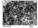
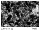
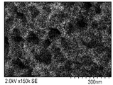
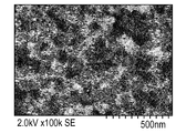
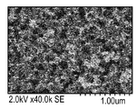
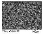
도 2는 본원에 기재된 방법을 사용하여 제조된 Fe-AAPyr 촉매의 SEM 이미지이다.
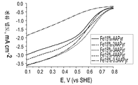
도 3은 본원에 기재된 방법을 사용하여 제조된 Fe-AAPyr 촉매에 대한 산소 환원을 보여주는 회전 디스크 전극(Rotating Disc Electrode) 전압전류곡선(electro-voltamogram)이다.
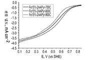
도 4는 다양한 열 처리 온도로 제조된 Fe-AAPyr 촉매에 대한 산소 환원을 보여주는 회전 디스크 전극 전압전류곡선이다.
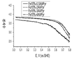
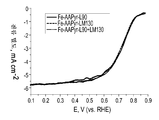
도 5는 본원에 기재된 바와 같이 제조된 다양한 Fe-AAPyr 촉매에 대한 ORR에 참여한 전자수의 그래프이다.
도 6은 본원에 기재된 바와 같이 제조된 다양한 Fe-AAPyr 촉매에 대한 과산화수소 수율의 그래프이다.
도 7은 본원에 기재된 바와 같이 제조된 Fe-AAPyr 촉매에 대한 ORR에 참여한 전자수의 그래프이다.
도 8은 본원에 기재된 바와 같이 제조된 다양한 Fe-AAPyr 촉매에 대한 과산화수소 수율의 그래프이다.
도 9는 본원에 기재된 바와 같이 멀티모달 세공 크기 분포를 갖는 촉매의 제조 방법의 개략도이다.
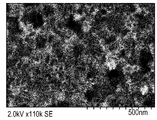
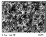
도 10a는 Fe-AAPyr 및 HS5 실리카로부터 유도된 모노-모달 촉매의 SEM 이미지이며, 이때 스케일 바는 500 nm이다.
도 10b는 Fe-AAPyr 및 HS5 실리카로부터 유도된 모노-모달 촉매의 SEM 이미지이며, 이때 스케일 바는 300 nm이다.
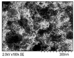
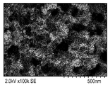
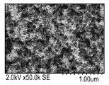
도 11a는 Fe-AAPyr 및 M5 실리카로부터 유도된 바이-모달 촉매의 SEM 이미지이며, 이때 스케일 바는 500 nm이다.
도 11b는 Fe-AAPyr 및 M5 실리카로부터 유도된 바이-모달 촉매의 SEM 이미지이며, 이때 스케일 바는 300 nm이다.
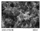
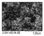
도 12a는 Fe-AAPyr 및 LM130 실리카로부터 유도된 바이-모달 촉매의 SEM 이미지이며, 이때 스케일 바는 500 nm이다.
도 12b는 Fe-AAPyr 및 LM130 실리카로부터 유도된 바이-모달 촉매의 SEM 이미지이며, 이때 스케일 바는 300 nm이다.
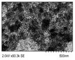
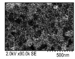
도 13a는 Fe-AAPyr 및 A90 실리카로부터 유도된 촉매의 SEM 이미지이며, 이때 스케일 바는 500 nm이다.
도 13b는 Fe-AAPyr 및 A90 실리카로부터 유도된 촉매의 SEM 이미지이며, 이때 스케일 바는 300 nm이다.
도 14는 Fe-AAPyr 및 L90과 A90 실리카의 혼합물로부터 유도된 바이-모달 촉매의 SEM 이미지이다.
도 15a는 Fe-AAPyr 및 L90과 EH5 실리카의 혼합물로부터 유도된 트리-모달 촉매의 SEM 이미지이며, 이때 스케일 바는 500 nm이다.
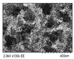
도 15b는 Fe-AAPyr 및 L90과 EH5 실리카의 혼합물로부터 유도된 트리-모달 촉매의 SEM 이미지이며, 이때 스케일 바는 400 nm이다.
도 15c는 Fe-AAPyr 및 L90과 EH5 실리카의 혼합물로부터 유도된 트리-모달 촉매의 SEM 이미지이며, 이때 스케일 바는 300 nm이다.
도 16은 Fe-AAPyr 및 L90과 M5 실리카의 혼합물로부터 유도된 바이-모달 촉매의 SEM 이미지이며, 이때 스케일 바는 500 nm이다.
도 17은 Fe-AAPyr 및 L90과 LM130 실리카의 혼합물로부터 유도된 바이-모달 촉매의 SEM 이미지이며, 이때 스케일 바는 500 nm이다.
도 18은 Fe-AAPyr 및 L90과 A200 실리카의 혼합물로부터 유도된 바이-모달 촉매의 SEM 이미지이다.
도 19는 Fe-AAPy 및 L90과 A380 실리카의 혼합물로부터 유도된 바이-모달 촉매의 SEM 이미지이다.
도 20a는 Fe-AAPyr 및 M5 실리카로부터 유도된 구형 촉매의 SEM 이미지이다.
도 20b는 Fe-AAPyr 및 M5 실리카로부터 유도된 구형 촉매의 또 다른 SEM 이미지이다.
도 20c는 Fe-AAPyr 및 M5 실리카로부터 유도된 구형 촉매의 또 다른 SEM 이미지이다.
도 20e는 Fe-AAPyr 및 M5 실리카로부터 유도된 구형 촉매의 또 다른 SEM 이미지이다.
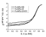
도 21은 Fe-AAPyr 및 HS5, L90 및 L90 + EH5 실리카로부터 제조된 촉매에 대한 RDE 데이터에 대한 산소 환원을 보여주는 회전 디스크 전극 전압전류곡선이다.
도 22는 Fe-AAPyr 및 L90, LM130, 및 L90 + LM130 실리카로부터 제조된 촉매에 대한 RDE 데이터에 대한 산소 환원을 보여주는 회전 디스크 전극 전압전류곡선이다.
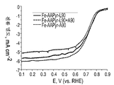
도 23은 Fe-AAPyr 및 L90, L90 + A90, 및 A90 실리카로부터 제조된 촉매에 대한 RDE 데이터에 대한 산소 환원을 보여주는 회전 디스크 전극 전압전류곡선이다.
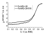
도 24는 Fe-AAPyr 및 L90 및 L90 + EH5 실리카로부터 제조된 촉매에 대한 RDE 데이터에 대한 산소 환원을 보여주는 회전 디스크 전극 전압전류곡선이다.
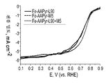
도 25는 Fe-AAPyr 및 L90, M5 및 L90 + M5 실리카로부터 제조된 촉매에 대한 RDE 데이터에 대한 산소 환원을 보여주는 회전 디스크 전극 전압전류곡선이다.
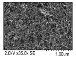
도 26은 본원에 기재된 방법을 사용하여 제조된 Fe3Co-AAPyr 촉매의 SEM 이미지이다.
도 27은 본원에 기재된 방법을 사용하여 제조된 FeCo-AAPyr 촉매의 SEM 이미지이다.
도 28은 본원에 기재된 방법을 사용하여 제조된 FeCo3-AAPyr 촉매의 SEM 이미지이다.
도 29a는 본원에 기재된 방법을 사용하여 제조된 FeCu3-AAPyr 2원-금속(bi-metallic) 촉매의 SEM 이미지이다.
도 29b는 본원에 기재된 방법을 사용하여 제조된 FeCu3-AAPyr 2원-금속 촉매의 또 다른 SEM 이미지이다.
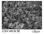
도 30a는 본원에 기재된 방법을 사용하여 제조된 FeMn3-AAPyr 2원-금속 촉매의 SEM 이미지이다.
도 30b는 본원에 기재된 방법을 사용하여 제조된 FeMn3-AAPyr 2원-금속 촉매의 또 다른 SEM 이미지이다.
도 31a는 본원에 기재된 방법을 사용하여 제조된 FeNi3-AAPyr 2원-금속 촉매의 SEM 이미지이다.
도 31b는 본원에 기재된 방법을 사용하여 제조된 FeNi3-AAPyr 2원-금속 촉매의 또 다른 SEM 이미지이다.
도 32a는 본원에 기재된 방법을 사용하여 제조된 FeCoCu-AAPyr 3원-금속(tri-metallic) 촉매의 SEM 이미지이다.
도 32b는 본원에 기재된 방법을 사용하여 제조된 FeCoCu-AAPyr 3원-금속 촉매의 또 다른 SEM 이미지이다.
도 33a는 본원에 기재된 방법을 사용하여 제조된 FeCoMn-AAPyr 3원-금속 촉매의 SEM 이미지이다.
도 33b는 본원에 기재된 방법을 사용하여 제조된 FeCoMn-AAPyr 3원-금속 촉매의 또 다른 SEM 이미지이다.
도 34a는 본원에 기재된 방법을 사용하여 제조된 FeCuMn-AAPyr 3원-금속 촉매의 SEM 이미지이다.
도 34b는 본원에 기재된 방법을 사용하여 제조된 FeCuMn-AAPyr 3원-금속 촉매의 또 다른 SEM 이미지이다.
도 35는 Co-AAPyr에 대비하여 FexCoy-AAPyr 2원-금속 촉매에 대한 산소 환원을 보여주는 회전 디스크 전극 전압전류곡선이다.
도 36은 Ni-AAPyr에 대비하여 FexNiy-AAPyr 2원-금속 촉매에 대한 산소 환원을 보여주는 회전 디스크 전극 전압전류곡선이다.
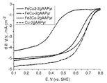
도 37은 Cu-AAPyr에 대비하여 FexCuy-AAPyr 2원-금속 촉매에 대한 산소 환원을 보여주는 회전 디스크 전극 전압전류곡선이다.
도 38은 Cr-AAPyr에 대비하여 FexCry-AAPyr 2원-금속 촉매에 대한 산소 환원을 보여주는 회전 디스크 전극 전압전류곡선이다.
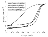
도 39는 Mn-AAPyr에 대비하여 FexMny-AAPyr 2원-금속 촉매에 대한 산소 환원을 보여주는 회전 디스크 전극 전압전류곡선이다.
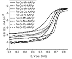
도 40은 FeMIMII-AAPyr 3원-금속 촉매에 대한 산소 환원을 보여주는 회전 디스크 전극 전압전류곡선이다.
도 41은 본원에 따라 M-N-C 촉매를 제조하기 위한 회분식(batch-wise) 공정의 개략도이다.
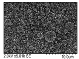
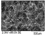
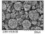
도 42a는 저 표면적 실리카 상에 제조된 고도로 다공성인 구형 Fe-N-C 촉매의 SEM 이미지이며, 이때 스케일 바는 10 μm이다.
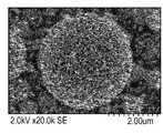
도 42b는 저 표면적 실리카 상에 제조된 고도로 다공성인 구형 Fe-N-C 촉매의 SEM 이미지이며, 이때 스케일 바는 2 μm이다.
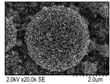
도 42c는 저 표면적 실리카 상에 제조된 고도로 다공성인 구형 Fe-N-C 촉매의 SEM 이미지이며, 이때 스케일 바는 1 μm이다.
도 42d는 저 표면적 실리카 상에 제조된 고도로 다공성인 구형 Fe-N-C 촉매의 SEM 이미지이며, 이때 스케일 바는 500 nm이다.
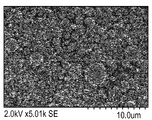
도 43a는 고 표면적 실리카 상에 제조된 고도로 다공성인 구형 Fe-N-C 촉매의 제1 배치의 SEM 이미지이며, 이때 스케일 바는 5 μm이다.
도 43b는 고 표면적 실리카 상에 제조된 고도로 다공성인 구형 Fe-N-C 촉매의 제1 배치의 SEM 이미지이며, 이때 스케일 바는 2 μm이다.
도 43c는 고 표면적 실리카 상에 제조된 고도로 다공성인 구형 Fe-N-C 촉매의 제1 배치의 SEM 이미지이며, 이때 스케일 바는 500 nm이다.
도 44a는 고 표면적 실리카 상에 제조된 고도로 다공성인 구형 Fe-N-C 촉매의 제2 배치의 SEM 이미지이며, 이때 스케일 바는 3 μm이다.
도 44b는 고 표면적 실리카 상에 제조된 고도로 다공성인 구형 Fe-N-C 촉매의 제2 배치의 SEM 이미지이며, 이때 스케일 바는 2 μm이다.
도 45는 O2로 포화된 0.5M H2SO4 중에서의 본원에 기재된 방법에 의해 제조된 구형 F-N-C 촉매에 대한 RDE 데이터에 대한 산소 환원을 보여주는 회전 디스크 전극 전압전류곡선이다 (촉매 로딩: 600 μg cm-2, 1200 RPM, 5 mV s-1).1 is an X-ray diffraction diagram of a Fe-MC catalyst prepared as described herein.
2 is an SEM image of a Fe-AAPyr catalyst prepared using the method described herein.
FIG. 3 is a Rotating Disc Electrode electro-voltamogram showing oxygen reduction for the Fe-AAPyr catalyst prepared using the methods described herein.
4 is a rotating disk electrode voltammetric curve showing oxygen reduction for Fe-AAPyr catalysts prepared at various heat treatment temperatures.
5 is a graph of the number of electrons participating in the ORR for various Fe-AAPyr catalysts prepared as described herein.
6 is a graph of hydrogen peroxide yields for various Fe-AAPyr catalysts prepared as described herein.
FIG. 7 is a graph of the number of electrons participating in the ORR for the Fe-AAPyr catalyst prepared as described herein.
8 is a graph of hydrogen peroxide yield for various Fe-AAPyr catalysts prepared as described herein.
9 is a schematic diagram of a method for preparing a catalyst having a multimodal pore size distribution as described herein.
10A is an SEM image of a mono-modal catalyst derived from Fe-AAPyr and HS5 silica, with scale bar 500 nm.
FIG. 10B is an SEM image of a mono-modal catalyst derived from Fe-AAPyr and HS5 silica, with a scale bar of 300 nm.
FIG. 11A is an SEM image of a bi-modal catalyst derived from Fe-AAPyr and M5 silica, with a scale bar of 500 nm.
FIG. 11B is an SEM image of a bi-modal catalyst derived from Fe-AAPyr and M5 silica, with a scale bar of 300 nm.
12A is an SEM image of a bi-modal catalyst derived from Fe-AAPyr and LM130 silica, with a scale bar of 500 nm.
FIG. 12B is an SEM image of a bi-modal catalyst derived from Fe-AAPyr and LM130 silica, with a scale bar of 300 nm.
FIG. 13A is an SEM image of a catalyst derived from Fe-AAPyr and A90 silica, with a scale bar of 500 nm.
FIG. 13B is an SEM image of a catalyst derived from Fe-AAPyr and A90 silica, with scale bar 300 nm.
FIG. 14 is an SEM image of a bi-modal catalyst derived from Fe-AAPyr and a mixture of L90 and A90 silica.
15A is an SEM image of a tri-modal catalyst derived from a mixture of Fe-AAPyr and L90 and EH5 silica, with a scale bar of 500 nm.
FIG. 15B is an SEM image of a tri-modal catalyst derived from a mixture of Fe-AAPyr and L90 and EH5 silica, with a scale bar of 400 nm.
15C is an SEM image of a tri-modal catalyst derived from a mixture of Fe-AAPyr and L90 and EH5 silica, with a scale bar of 300 nm.
FIG. 16 is an SEM image of a bi-modal catalyst derived from Fe-AAPyr and a mixture of L90 and M5 silica, with a scale bar of 500 nm.
FIG. 17 is an SEM image of a bi-modal catalyst derived from a mixture of Fe-AAPyr and L90 and LM130 silica, with a scale bar of 500 nm.
18 is an SEM image of a bi-modal catalyst derived from Fe-AAPyr and a mixture of L90 and A200 silica.
19 is an SEM image of a bi-modal catalyst derived from Fe-AAPy and a mixture of L90 and A380 silica.
20A is an SEM image of spherical catalyst derived from Fe-AAPyr and M5 silica.
20B is another SEM image of the spherical catalyst derived from Fe-AAPyr and M5 silica.
20C is another SEM image of a spherical catalyst derived from Fe-AAPyr and M5 silica.
20E is another SEM image of a spherical catalyst derived from Fe-AAPyr and M5 silica.
FIG. 21 is a rotating disk electrode voltammetric curve showing oxygen reduction for RDE data for catalysts prepared from Fe-AAPyr and HS5, L90 and L90 + EH5 silica.
FIG. 22 is a rotating disk electrode voltammogram showing oxygen reduction for RDE data for catalysts made from Fe-AAPyr and L90, LM130, and L90 + LM130 silica.
FIG. 23 is a rotating disk electrode voltammetric curve showing oxygen reduction for RDE data for catalysts prepared from Fe—AAPyr and L90, L90 + A90, and A90 silica.
24 is a rotating disk electrode voltammetric curve showing oxygen reduction for RDE data for catalysts prepared from Fe-AAPyr and L90 and L90 + EH5 silica.
FIG. 25 is a rotating disk electrode voltammetric curve showing oxygen reduction for RDE data for catalysts prepared from Fe-AAPyr and L90, M5 and L90 + M5 silica.
FIG. 26 is an SEM image of a Fe 3 Co-AAPyr catalyst prepared using the method described herein.
FIG. 27 is an SEM image of a FeCo-AAPyr catalyst prepared using the method described herein.
FIG. 28 is an SEM image of a FeCo 3 -AAPyr catalyst prepared using the method described herein.
29A is an SEM image of a FeCu 3 -AAPyr bi-metallic catalyst prepared using the method described herein.
29B is another SEM image of a FeCu 3 -AAPyr binary-metal catalyst prepared using the method described herein.
30A is an SEM image of a FeMn 3 -AAPyr binary-metal catalyst prepared using the method described herein.
30B is another SEM image of a FeMn 3 -AAPyr binary-metal catalyst prepared using the method described herein.
FIG. 31A is an SEM image of a FeNi 3 -AAPyr binary-metal catalyst prepared using the method described herein.
FIG. 31B is another SEM image of a FeNi 3 -AAPyr binary-metal catalyst prepared using the method described herein.
32A is an SEM image of a FeCoCu-AAPyr tri-metallic catalyst prepared using the method described herein.
32B is another SEM image of a FeCoCu-AAPyr three-metal catalyst prepared using the method described herein.
33A is an SEM image of a FeCoMn-AAPyr three-metal catalyst prepared using the method described herein.
FIG. 33B is another SEM image of a FeCoMn-AAPyr three-metal catalyst prepared using the method described herein.
34A is an SEM image of a FeCuMn-AAPyr three-metal catalyst prepared using the method described herein.
34B is another SEM image of a FeCuMn-AAPyr three-metal catalyst prepared using the method described herein.
35 is a rotating disk electrode voltammetric curve showing oxygen reduction for a Fe x Co y -AAPyr binary-metal catalyst relative to Co-AAPyr.
36 is a rotating disk electrode voltammetric curve showing oxygen reduction for a Fe x Ni y -AAPyr binary-metal catalyst relative to Ni-AAPyr.
FIG. 37 is a rotating disk electrode voltammetric curve showing oxygen reduction for a Fe x Cu y -AAPyr binary-metal catalyst relative to Cu-AAPyr.
38 is a rotating disk electrode voltammetric curve showing oxygen reduction for a Fe x Cr y -AAPyr binary-metal catalyst relative to Cr-AAPyr.
FIG. 39 is a rotating disk electrode voltammogram showing oxygen reduction for Fe x Mn y -AAPyr binary-metal catalysts compared to Mn-AAPyr.
40 is a rotating disk electrode voltammetric curve showing oxygen reduction for FeM I M II -AAPyr ternary-metal catalyst.
FIG. 41 is a schematic of a batch-wise process for preparing an MNC catalyst according to the present disclosure. FIG.
42A is an SEM image of a highly porous spherical Fe-NC catalyst prepared on low surface area silica, with a scale bar of 10 μm.
42B is an SEM image of a highly porous spherical Fe-NC catalyst prepared on low surface area silica, with a scale bar of 2 μm.
42C is an SEM image of a highly porous spherical Fe-NC catalyst prepared on low surface area silica, with a scale bar of 1 μm.
42D is an SEM image of a highly porous spherical Fe-NC catalyst prepared on low surface area silica with a scale bar of 500 nm.
43A is an SEM image of a first batch of highly porous spherical Fe-NC catalyst prepared on high surface area silica with a scale bar of 5 μm.
43B is an SEM image of a first batch of highly porous spherical Fe-NC catalyst prepared on high surface area silica, with a scale bar of 2 μm.
43C is an SEM image of a first batch of highly porous spherical Fe-NC catalyst prepared on high surface area silica, with a scale bar of 500 nm.
44A is an SEM image of a second batch of highly porous spherical Fe-NC catalyst prepared on high surface area silica with a scale bar of 3 μm.
FIG. 44B is an SEM image of a second batch of highly porous spherical Fe-NC catalyst prepared on high surface area silica with a scale bar of 2 μm.
45 is a rotating disk electrode voltammogram showing oxygen reduction for RDE data for spherical FNC catalysts prepared by the method described herein in 0.5MH 2 SO 4 saturated with O 2 (catalyst loading: 600 μg cm -2 , 1200 RPM, 5 mV s -1 ).
상세한 설명details
한 실시양태에 따르면, 본원은 신규한 촉매 및 그의 제조 방법을 제공한다. M-N-C 촉매를 형성하기 위한 앞서 기재된 방법에서, 질소 및 탄소의 공급원은 전형적으로 초기 촉매 활성을 갖는 포르피린 전구체이다. 이러한 초기 촉매 활성은 이의 금속 입자와의 착물 형성(complexing)시에 개선된다. 본원은 질소 및 탄소의 공급원으로서 초기 촉매 활성을 갖지 않는 비-포르피린 전구체를 사용함으로써 M-N-C 촉매가 합성될 수 있다는 놀랍고도 예기치 않은 발견에 의지한다. 적합한 비-촉매성 비-포르피린 전구체의 예에는 철과의 착물을 형성하는 저분자량 전구체 (예컨대, 4-아미노안티피린, 페닐렌디아민, 히드록시숙신이미드, 에탄올아민 등)이 포함되지만 반드시 이로 한정되는 것은 아니다. 일부 실시양태에 따르면, 비-촉매성 전구체는 철과 착물을 형성할 수 있는 그들의 능력으로 인해 선택될 수 있다. 또 다른 실시양태에 따르면, 비-촉매성 전구체는, 이들이 초기 촉매 활성을 갖는 전구체 내의 활성 부위와 동일하거나 유사한 모이어티(moiety)를 함유하기 때문에 선택될 수 있는데, 이어서 이의 결정 구조는 고온 열 처리에 의해 안정화된다.According to one embodiment, the present disclosure provides novel catalysts and methods for their preparation. In the previously described method for forming the M-N-C catalyst, the source of nitrogen and carbon is typically a porphyrin precursor with initial catalytic activity. This initial catalytic activity is improved upon complexing with its metal particles. The present application relies on the surprising and unexpected finding that M-N-C catalysts can be synthesized by using non-porphyrin precursors that do not have initial catalytic activity as a source of nitrogen and carbon. Examples of suitable non-catalytic non-porphyrin precursors include, but are not limited to, low molecular weight precursors (eg, 4-aminoantipyrine, phenylenediamine, hydroxysuccinimide, ethanolamine, etc.) that form complexes with iron. It doesn't happen. According to some embodiments, non-catalytic precursors may be selected due to their ability to complex with iron. According to another embodiment, non-catalytic precursors may be selected because they contain the same or similar moiety as the active site in the precursor having initial catalytic activity, the crystal structure of which is then subjected to high temperature heat treatment Stabilized by
한 실시양태에 따르면, 본원에 따른 M-N-C 촉매는 질산철 형태의 철 전구체 및 4-아미노안티피린 (AAPyr) 형태의 C-N 전구체를 발연 실리카의 희생 지지체의 표면 상에 습식 함침시킴으로써 제조될 수 있다. 다른 적합한 철 전구체에는 황산철, 아세트산철, 염화철 등이 포함되지만 이로 한정되는 것은 아니다.According to one embodiment, the M-N-C catalyst according to the invention can be prepared by wet impregnation of the iron precursor in the form of iron nitrate and the C-N precursor in the form of 4-aminoantipyrine (AAPyr) on the surface of the sacrificial support of fumed silica. Other suitable iron precursors include, but are not limited to, iron sulfate, iron acetate, iron chloride, and the like.
다른 전이 금속, 예컨대 Ce, Cr, Cu Mo, Ni, Ru, Ta, Ti, V, W 및 Zr이, 단순히 그 대신 그러한 금속의 전구체를 사용함으로써, 철 대신 사용될 수 있다는 것을 이해할 것이다. 예시적인 전이 금속 전구체에는 질산세륨, 질산크로뮴, 질산구리, 몰리브데넘산암모늄, 질산니켈, 염화루테늄, 탄탈럼 이소프로폭시드, 티타늄 에톡시드, 황산바나듐, 텅스텐산암모늄 및 질산지르코늄이 포함되지만 이로 한정되는 것은 아니다. 더욱이, 일부 실시양태에 따르면, 그리고 하기에 더 상세히 기재된 바와 같이, 본원에 기재된 방법은 둘 이상의 금속의 전구체를 이용하여 다중-금속(multi-metallic) 촉매를 생성할 수 있다.It will be appreciated that other transition metals such as Ce, Cr, Cu Mo, Ni, Ru, Ta, Ti, V, W and Zr may be used instead of iron by simply using precursors of such metal instead. Exemplary transition metal precursors include cerium nitrate, chromium nitrate, copper nitrate, ammonium molybdate, ammonium nitrate, ruthenium chloride, tantalum isopropoxide, titanium ethoxide, vanadium sulfate, ammonium tungstate and zirconium nitrate It is not limited to this. Moreover, according to some embodiments, and as described in more detail below, the methods described herein may utilize multi-metallic catalysts using precursors of two or more metals.
적합한 희생 지지체에는 실리카, 제올라이트, 알루미나 등이 포함되지만 이로 한정되는 것은 아니다. 지지체는 구체, 입자, 또는 다른 2차원 또는 3차원적 규칙, 불규칙, 또는 무정형 형상의 형태를 취할 수 있다. 구체, 입자, 또는 다른 형상은 단분산이거나, 또는 불규칙한 크기를 가질 수 있다. 구체, 입자, 또는 다른 형상은 세공을 가질 수 있거나 가질 수 없으며, 그러한 세공은 동일하거나 상이한 크기 및 형상을 가질 수 있다.Suitable sacrificial supports include, but are not limited to, silica, zeolites, alumina, and the like. The support may take the form of spheres, particles, or other two or three dimensional regular, irregular, or amorphous shapes. Spheres, particles, or other shapes may be monodisperse or have an irregular size. Spheres, particles, or other shapes may or may not have pores, and such pores may have the same or different sizes and shapes.
하기에 더 상세히 기재된 바와 같이, 실리카 입자의 크기 및 형상은 전기촉매 물질 내의 공극의 원하는 형상(들) 및 크기(들)에 따라 선택될 수 있다는 것을 이해해야 한다. 따라서, 실리카 입자의 특정 크기 및 형상을 선택함으로써, 예측가능한 크기 및 형상의 공극을 갖는 전기촉매를 생성할 수 있다. 예를 들어, 실리카 입자가 구체일 경우, 전기촉매는 복수의 구형 공극을 함유할 것이다. 당업자는 복수의 백금-루테늄 합금 구체로 이루어진 전기촉매 Pt-Ru 블랙에 친숙할 것이다. 상기에 기재된 방법으로 실리카 구체를 사용하여 형성된 전기촉매는 Pt-Ru 블랙의 네거티브 이미지처럼 보이는데; Pt-Ru 블랙 내에 공극으로서 존재했던 공간은 금속 전기촉매로 충전되고, Pt-Ru 블랙 내에 금속 전기촉매로서 존재했던 공간은 공극이다.As described in more detail below, it should be understood that the size and shape of the silica particles can be selected according to the desired shape (s) and size (s) of the pores in the electrocatalyst material. Thus, by selecting a particular size and shape of the silica particles, it is possible to produce an electrocatalyst with pores of predictable size and shape. For example, if the silica particles are spheres, the electrocatalyst will contain a plurality of spherical pores. Those skilled in the art will be familiar with the electrocatalyst Pt-Ru black consisting of a plurality of platinum-ruthenium alloy spheres. Electrocatalysts formed using silica spheres in the manner described above look like negative images of Pt-Ru black; Spaces that existed as voids in the Pt-Ru black are filled with metal electrocatalysts, and spaces that existed as metal electrocatalysts in the Pt-Ru black are voids.
상기에 기재된 바와 같이, 일부 실시양태에 따르면, 임의의 직경의 실리카 구체가 사용될 수 있다. 일부 바람직한 실시양태에서는, 특성 길이가 1 nm 내지 100 nm인 실리카 입자, 보다 바람직한 실시양태에서는, 특성 길이가 100 nm 내지 1000 nm인 실리카 입자가 사용될 수 있으며, 다른 바람직한 실시양태에서는, 특성 길이가 1 mm 내지 10 mm인 실리카 입자가 사용될 수 있다. 추가로, 메조다공성 실리카가 또한 템플레이팅 합성 접근법에 사용될 수 있다. 이 경우에, 템플레이팅은 물질의 메조세공들을 삽입하는 것을 포함하며, 그 결과 다공도가 2 내지 20 nm 범위인 자기-지지된 전기촉매가 생성된다. 한 특정 실시양태에서, 실리카 템플레이트는 캅오실(Cabosil) 무정형 발연 실리카 (325 m2/g)이다. 상기에 기재된 바와 같이, 구체는 전기촉매의 형성을 위한 템플레이트로서의 역할을 하기 때문에, 평균 직경이 20 nm인 실리카 입자가 사용되는 실시양태에서, 전기촉매 내의 구형 공극은 전형적으로 대략 20 nm의 직경을 가질 것이다. 당업자는 구매가능한 다양한 실리카 입자에 친숙할 것이며, 그러한 입자가 사용될 수 있다. 대안적으로, 원하는 형상 및/또는 크기의 입자를 수득하기 위해 실리카 입자를 형성하는 공지된 방법이 사용될 수 있다.As described above, according to some embodiments, silica spheres of any diameter may be used. In some preferred embodiments, silica particles having a characteristic length of 1 nm to 100 nm, in more preferred embodiments, silica particles having a characteristic length of 100 nm to 1000 nm may be used, and in other preferred embodiments, the characteristic length is 1 Silica particles of between mm and 10 mm can be used. In addition, mesoporous silica can also be used in the template synthesis approach. In this case, the template involves inserting mesopores of the material, resulting in a self-supported electrocatalyst having a porosity in the range of 2-20 nm. In one particular embodiment, the silica template is Cabosil amorphous fumed silica (325 m 2 / g). As described above, since the spheres serve as templates for the formation of the electrocatalyst, in embodiments where silica particles having an average diameter of 20 nm are used, the spherical pores in the electrocatalyst typically have a diameter of approximately 20 nm. Will have Those skilled in the art will be familiar with the various silica particles available on the market, and such particles can be used. Alternatively, known methods of forming silica particles can be used to obtain particles of the desired shape and / or size.
C-N 전구체 및 금속 전구체를 희생 지지체 상에 침적 및/또는 함침시킨 후에, 촉매는 N2, Ar 또는 He와 같은 불활성 분위기 내에서, 또는 NH3 또는 아세토니트릴과 같은 반응성 분위기 내에서 열 처리된다. C-N 전구체에 질소가 풍부한 경우에는 불활성 분위기가 전형적으로 사용되는데, 이는 불활성 분위기는 Fe (또는 다른 금속) N4 중심을 갖는 활성 부위를 많이 생성할 수 있게 하기 때문이다. 그러나, C-N 전구체에 탄소가 풍부하고 질소가 결핍된 경우에는 질소 풍부 분위기를 사용하도록 요구될 수 있는데, 이는 질소 풍부 분위기는 Fe (또는 다른 금속) N4 중심의 생성을 가능하게 할 것이기 때문이다.After depositing and / or impregnating the CN precursor and the metal precursor onto the sacrificial support, the catalyst is heat treated in an inert atmosphere such as N 2 , Ar or He, or in a reactive atmosphere such as NH 3 or acetonitrile. Inert atmospheres are typically used when the CN precursor is rich in nitrogen because the inert atmosphere allows for the generation of many active sites with Fe (or other metal) N4 centers. However, if the CN precursor is rich in carbon and lacks nitrogen, it may be required to use a nitrogen rich atmosphere, since the nitrogen rich atmosphere will enable the generation of Fe (or other metal) N4 centers.
한 실시양태에 따르면, 열 처리를 위한 최적 온도는 500 내지 1100℃이다. 일부 실시양태에 따르면, 800 내지 900℃의 열 처리가 바람직한데, 이는 이 온도는 물질을 열분해시키기에는 충분히 높지만 전형적으로 활성 부위를 파괴시키기에는 충분히 높지 않기 때문이다.According to one embodiment, the optimum temperature for heat treatment is 500 to 1100 ° C. According to some embodiments, a thermal treatment of 800 to 900 ° C. is preferred because this temperature is high enough to pyrolyze the material but typically not high enough to destroy the active site.
열 처리 후에는, 적합한 수단을 사용하여 희생 지지체를 제거한다. 예를 들어, 희생 지지체는 화학적 에칭을 통해 제거될 수 있다. 적합한 에천트(etchant)의 예에는 NaOH, KOH, 및 HF가 포함된다. 일부 실시양태에 따르면, KOH를 사용하는 것이 바람직할 수 있는데, 이는 그것이 촉매 내의 모든 금속 및 금속 산화물을 보존하기 때문이며, 이들 종이 촉매 활성일 경우, KOH의 사용은 실제로 촉매 활성을 증가시킬 수 있기 때문이다. 대안적으로, 일부 실시양태에서는, HF가 바람직할 수 있는데, 이는 그것이 매우 공격적이며 촉매의 표면으로부터 일부 독성 종을 제거하는 데 사용될 수 있기 때문이다. 따라서, 당업자는 형성되는 특정 촉매 물질의 특정 요건에 기초하여 원하는 에천트를 선택할 수 있을 것이다.After heat treatment, the sacrificial support is removed using suitable means. For example, the sacrificial support can be removed through chemical etching. Examples of suitable etchants include NaOH, KOH, and HF. According to some embodiments, it may be desirable to use KOH, because it preserves all metals and metal oxides in the catalyst, and if these species are catalytically active, the use of KOH can actually increase the catalytic activity. to be. Alternatively, in some embodiments, HF may be preferred because it is very aggressive and can be used to remove some toxic species from the surface of the catalyst. Thus, those skilled in the art will be able to select the desired etchant based on the specific requirements of the particular catalyst material formed.
구체적인 예시적 실시양태에 따르면, 철 전구체 및 아미노안티피린 전구체를 발연 실리카 (캅-오-실(Cab-O-Sil)™ EH-5, 표면적: 약 400 m2 g-1)의 표면 상에 습식 함침시킴으로써 Fe-AAPyr 촉매를 제조하였다. 먼저, 1 g의 실리카를 소노배쓰(sonobath)를 사용하여 물 중에 분산시켰다. 이어서, 물 중 1 g의 AAPyr의 용액을 실리카에 첨가하고 20분 동안 초음파처리하였다. 이어서, 1 g의 질산철 (Fe(NO3)3·9H2O, 시그마-알드리치(Sigma-Aldrich))의 수용액을 SiO2-AAPyr 용액에 첨가하고, 이어서 소노배쓰 내에서 8시간 동안 초음파처리하였다. 초음파처리 후, 실리카 및 Fe-AAPyr의 점성 용액을 T=85℃에서 하룻밤 건조시켰다. 고형물을 마노 유발 내에서 미세 분말로 분쇄하고, 이어서 열 처리 (HT)를 가하였다. HT의 조건은 다음과 같았다: 100 cc min-1의 속도로 유동하는 UHP N2 분위기, HT 온도 800℃, HT 온도 상승률 10℃ min-1, 및 HT 지속시간 1시간.According to a specific exemplary embodiment, the iron precursor and the aminoantipyrine precursor are wetted onto the surface of fumed silica (Cab-O-Sil ™ EH-5, surface area: about 400 m 2 g −1 ) Fe-AAPyr catalyst was prepared by impregnation. First, 1 g of silica was dispersed in water using a sonobath. Then a solution of 1 g of AAPyr in water was added to the silica and sonicated for 20 minutes. Subsequently, an aqueous solution of 1 g of iron nitrate (Fe (NO 3 ) 3 .9H 2 O, Sigma-Aldrich) is added to the SiO 2 -AAPyr solution, followed by sonication in a sonobath for 8 hours. It was. After sonication, a viscous solution of silica and Fe-AAPyr was dried at T = 85 ° C. overnight. The solid was ground to a fine powder in agate mortar, followed by heat treatment (HT). The conditions of HT were as follows: UHP N 2 atmosphere flowing at a rate of 100 cc min −1 , HT temperature 800 ° C., HT temperature rise
도 1 및 도 2는 본원에 기재된 방법을 사용하여 제조된 선택된 M-N-C 촉매에 대한 구조적 및 형태학적 데이터를 보여준다.1 and 2 show structural and morphological data for selected M-N-C catalysts prepared using the methods described herein.
도 1은 금속 공급원으로서 질산철로부터, 그리고 질소 및 탄소 공급원으로서 AAPyr로부터 제조된 Fe-M-C 촉매가 탄소 매트릭스 내로 매립된 철의 나노입자 (2 nm 미만)로 주로 이루어지는 것을 보여주는 X선 회절도이다.FIG. 1 is an X-ray diffraction diagram showing that the Fe—M—C catalyst prepared from iron nitrate as a metal source and from AAPyr as a nitrogen and carbon source consists mainly of nanoparticles (less than 2 nm) of iron embedded into a carbon matrix.
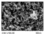
도 2는 본원에 기재된 방법을 사용하여 제조된 Fe-AAPyr 촉매의 SEM 이미지인데, 이는 이 물질이 세공 크기가 약 50 내지 70 nm인 고도로 발달된 다공성 구조를 갖는다는 것을 보여준다. 이러한 다공성은 산소 환원 쪽으로 촉매 특성을 개선하는 것으로 여겨진다.FIG. 2 is an SEM image of the Fe-AAPyr catalyst prepared using the method described herein, which shows that the material has a highly developed porous structure with pore sizes of about 50-70 nm. This porosity is believed to improve catalyst properties towards oxygen reduction.
도 3 및 도 4는 산소 환원 시험의 결과를 나타내며, 이에 따라 본원에 기재된 물질의 유용성을 입증한다.3 and 4 show the results of the oxygen reduction test, thus demonstrating the usefulness of the materials described herein.
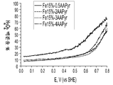
도 3은 O2로 포화된 0.5M H2SO4 중에서의 상이한 양의 아미노안티피린 전구체로 제조된 Fe-AAPyr 촉매에 대한 산소 환원을 보여주는 회전 디스크 전극 전압전류곡선이다 (촉매 로딩 160 mg cm-2, 1600 RPM, 스캔 속도 20 mV s-1).FIG. 3 is a rotating disk electrode voltammogram showing oxygen reduction for Fe-AAPyr catalyst prepared with different amounts of aminoantipyrine precursor in 0.5MH 2 SO 4 saturated with O 2 (catalyst loading 160 mg cm −2 , 1600 RPM,
도 4는 O2로 포화된 0.5M H2SO4 중에서의 다양한 열 처리 온도로 제조된 Fe-AAPyr에 대한 산소 환원을 보여주는 회전 디스크 전극 전압전류곡선이다 (촉매 로딩 160 mg cm-2, 1600 RPM, 스캔 속도 20 mV s-1).FIG. 4 is a rotating disk electrode voltammetric curve showing oxygen reduction for Fe-AAPyr prepared at various heat treatment temperatures in 0.5MH 2 SO 4 saturated with O 2 (catalyst loading 160 mg cm −2 , 1600 RPM,
이들 반응 시험은 저렴한 헤테로원자 아민 전구체 및 본원에 개시된 방법을 사용하여 제조된 M-N-C 촉매가 알칼리 및 산 매질 둘 다의 매질 중에서 높은 활성을 가지며, 따라서 또한 중성 pH에서도 활성임을 입증한다.These reaction tests demonstrate that the inexpensive heteroatomic amine precursors and the M-N-C catalysts prepared using the methods disclosed herein have high activity in the medium of both alkali and acid mediums and are therefore also active at neutral pH.
도 5 내지 도 8은 본원에 기재된 바와 같이 제조된 촉매의 메카니즘 연구를 보여주고 낮은 H2O2 생성 수율을 나타내며, 이에 따라 이는 더 효율적인 4 전자 메카니즘을 거쳐 진행되는 반응 경로임을 나타낸다.5-8 show a mechanism study of catalysts prepared as described herein and with low H 2 O 2 Yield yield is shown, thus indicating that the reaction pathway proceeds through a more efficient four electron mechanism.
도 5는 O2로 포화된 0.5M H2SO4 중에서의 아미노안티피린 전구체의 양의 변동을 갖는 Fe-AAPyr 촉매에 대한 ORR에 참여한 전자수의 그래프이다 (촉매 로딩: 160 mg cm-2, 1600 RPM, 20 mV s-1).5 is 0.5MH 2 SO 4 saturated with O 2 It is a graph of the number of electrons involved in the ORR for Fe-AAPyr catalyst with a change in the amount of aminoantipyrine precursor in the medium (catalyst loading: 160 mg cm −2 , 1600 RPM, 20 mV s −1 ).
도 6은 O2로 포화된 0.5M H2SO4 중에서의 상이한 양의 아미노안티피린 전구체로 제조된 Fe-AAPyr 촉매에 대한 과산화수소 수율의 그래프이다 (촉매 로딩: 160 mg cm-2, 1600 RPM, 20 mV s-1).6 is 0.5MH 2 SO 4 saturated with O 2 Is a graph of hydrogen peroxide yield for Fe-AAPyr catalysts prepared with different amounts of aminoantipyrine precursor in (catalyst loading: 160 mg cm −2 , 1600 RPM, 20 mV s −1 ).
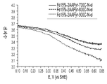
도 7은 O2로 포화된 0.5M H2SO4 중에서의 열 처리 온도를 변동시키면서 제조된 Fe-AAPyr 촉매에 대한 ORR에 참여한 전자수의 그래프이다 (촉매 로딩: 160 mg cm-2, 1600 RPM, 20 mV s-1).7 is 0.5MH 2 SO 4 saturated with O 2 Is a graph of the number of electrons participating in the ORR for the Fe-AAPyr catalyst prepared while varying the heat treatment temperature in the catalyst (catalyst loading: 160 mg cm −2 , 1600 RPM, 20 mV s −1 ).
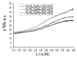
도 8은 O2로 포화된 0.5M H2SO4 중에서의 열 처리 온도를 변동시키면서 제조된 Fe-AAPyr에 대한 과산화수소 수율의 그래프이다 (촉매 로딩: 160 mg cm-2, 1600 RPM, 20 mV s-1).8 is 0.5MH 2 SO 4 saturated with O 2 Is a graph of hydrogen peroxide yield for Fe-AAPyr prepared with varying heat treatment temperature (catalyst loading: 160 mg cm −2 , 1600 RPM, 20 mV s −1 ).
상기에 기재된 바와 같이, 산소 환원의 메카니즘은 바람직한 4 전자 경로에 의한 산소의 물로의 직접 환원을 나타내며, 이에 따라 부식성 과산화물의 생성을 피하며, 그러므로 생성된 촉매의 안정성 및 내구성을 개선한다. As described above, the mechanism of oxygen reduction represents the direct reduction of oxygen to water by the preferred four electron path, thus avoiding the formation of corrosive peroxides and thus improving the stability and durability of the resulting catalyst.
도 3, 도 5, 및 도 6에서 입증된 바와 같이, 생성된 촉매의 특성은 제조 방법에 사용될 질소-함유 전구체의 양을 선택함으로써 변동될 수 있다. 일반적으로, 촉매 내의 질소의 농도가 더 높을수록, ORR에서의 활성이 더 높다. 더욱이, 도 4, 도 7 및 도 8에서 입증된 바와 같이, 촉매의 특성은 또한 열 처리 온도를 변동시킴으로써 변경될 수 있다. 전이 금속 및 C-N 전구체의 조합 각각에 대하여 열 처리 온도를 최적화하는 것이 바람직하다는 것을 이해할 것인데, 이는 너무 낮은 온도는 활성 부위를 생성시키지 않을 것이며, 너무 높은 온도는 물질을 분해시킬 것이다.As demonstrated in FIGS. 3, 5, and 6, the properties of the resulting catalyst can be varied by selecting the amount of nitrogen-containing precursor to be used in the production process. In general, the higher the concentration of nitrogen in the catalyst, the higher the activity in the ORR. Moreover, as demonstrated in FIGS. 4, 7 and 8, the properties of the catalyst can also be altered by varying the heat treatment temperature. It will be appreciated that it is desirable to optimize the heat treatment temperature for each combination of transition metal and C-N precursor, which is too low will not produce active sites and too high will degrade the material.
상기에 언급된 바와 같이, 본원에 기재된 방법은 비-철 금속, 예컨대 Co, Ni, Cu, Cr, Mn 등으로부터 촉매를 제조하는 데 사용될 수 있다.As mentioned above, the methods described herein can be used to prepare catalysts from non-ferrous metals such as Co, Ni, Cu, Cr, Mn and the like.
구체적인 비제한적 실시예로서, 철 전구체 및 아미노안티피린 전구체를 발연 실리카 (캅-오-실™ EH-5, 표면적: 약 400 m2 g-1)의 표면 상에 습식 함침시킴으로써 Fe-AAPyr 촉매를 제조하였다. 먼저, 1 g의 실리카를 소노배쓰를 사용하여 물 중에 분산시켰다. 이어서, 물 중 1 g의 AAPyr의 용액을 실리카에 첨가하고 20분 동안 초음파처리하였다. 이어서, 1 g의 질산철 (Fe(NO3)3·9H2O, 시그마-알드리치)의 수용액을 SiO2-AAPyr 용액에 첨가하고, 이어서 소노배쓰 내에서 8시간 동안 초음파처리하였다. 초음파처리 후, 실리카 및 Fe-AAPyr의 점성 용액을 T=85℃에서 하룻밤 건조시켰다. 고형물을 마노 유발 내에서 미세 분말로 분쇄하고, 이어서 열 처리 (HT)를 가하였다. HT의 조건은 다음과 같았다: 100 cc min-1의 속도로 유동하는 UHP N2 분위기, HT 온도 800℃, HT 온도 상승률 10℃ min-1, 및 HT 지속시간 1시간.As a specific non-limiting example, the Fe-AAPyr catalyst is prepared by wet impregnation of an iron precursor and an aminoantipyrine precursor onto a surface of fumed silica (Cap-O-Syl ™ EH-5, surface area: about 400 m 2 g -1 ). It was. First, 1 g of silica was dispersed in water using a sonobath. Then a solution of 1 g of AAPyr in water was added to the silica and sonicated for 20 minutes. Subsequently, an aqueous solution of 1 g of iron nitrate (Fe (NO 3 ) 3 .9H 2 O, Sigma-Aldrich) was added to the SiO 2 -AAPyr solution, followed by sonication in a sonobath for 8 hours. After sonication, a viscous solution of silica and Fe-AAPyr was dried at T = 85 ° C. overnight. The solid was ground to a fine powder in agate mortar, followed by heat treatment (HT). The conditions of HT were as follows: UHP N 2 atmosphere flowing at a rate of 100 cc min −1 , HT temperature 800 ° C., HT temperature rise
또 다른 비제한적 실시예에 따르면, 철 전구체, 망가니즈 전구체 및 아미노안티피린 전구체를 발연 실리카 (캅-오-실™ EH-5, 표면적: 약 400 m2 g-1)의 표면 상에 습식 함침시킴으로써 Fe-Mn-AAPyr 촉매를 제조하였다. 먼저, 3 g의 실리카를 소노배쓰를 사용하여 물 중에 분산시켰다. 이어서, 물 중 1.98 g의 AAPyr의 용액을 실리카에 첨가하고 20분 동안 초음파처리하였다. 이어서, 1.4 g의 질산철 (Fe(NO3)3·9H2O, 시그마-알드리치) 및 3.2g의 질산망가니즈의 수용액을 SiO2-AAPyr 용액에 첨가하고, 이어서 소노배쓰 내에서 8시간 동안 초음파처리하였다. 초음파처리 후, 실리카 및 Fe-Mn-AAPyr의 점성 용액을 T=85℃에서 하룻밤 건조시켰다. 고형물을 마노 유발 내에서 미세 분말로 분쇄하고, 이어서 열 처리 (HT)를 가하였다. HT의 조건은 다음과 같았다: 100 cc min-1의 속도로 유동하는 UHP N2 분위기, HT 온도 800℃, HT 온도 상승률 10℃ min-1, 및 HT 지속시간 1시간.According to another non-limiting example, the iron precursor, manganese precursor and aminoantipyrine precursor are wet-impregnated onto the surface of fumed silica (Cap-O-sil ™ EH-5, surface area: about 400 m 2 g -1 ) Fe-Mn-AAPyr catalyst was prepared. First, 3 g of silica was dispersed in water using a sonobath. Then a solution of 1.98 g of AAPyr in water was added to the silica and sonicated for 20 minutes. Then 1.4 g of iron nitrate (Fe (NO 3 ) 3 .9H 2 O, Sigma-Aldrich) and 3.2 g of aqueous solution of manganese nitrate were added to the SiO 2 -AAPyr solution, followed by 8 hours in a sonobath. Ultrasonicated. After sonication, a viscous solution of silica and Fe-Mn-AAPyr was dried at T = 85 ° C. overnight. The solid was ground to a fine powder in agate mortar, followed by heat treatment (HT). The conditions of HT were as follows: UHP N 2 atmosphere flowing at a rate of 100 cc min −1 , HT temperature 800 ° C., HT temperature rise
또 다른 비제한적 실시양태에 따르면, 철 전구체 및 아미노안티피린 전구체를 발연 실리카 (캅-오-실™ EH-5, 표면적: 약 400 m2 g-1)의 표면 상에 습식 함침시킴으로써 Fe-Cr-AAPyr 촉매를 제조하였다. 먼저, 2 g의 실리카를 소노배쓰를 사용하여 물 중에 분산시켰다. 이어서, 물 중 3.5 g의 AAPyr의 용액을 실리카에 첨가하고 20분 동안 초음파처리하였다. 이어서, 1 g의 질산철 (Fe(NO3)3·9H2O, 시그마-알드리치) 및 1.25 g의 질산크로뮴의 수용액을 SiO2-AAPyr 용액에 첨가하고, 이어서 소노배쓰 내에서 8시간 동안 초음파처리하였다. 초음파처리 후, 실리카 및 Fe-AAPyr의 점성 용액을 T=85℃에서 하룻밤 건조시켰다. 고형물을 마노 유발 내에서 미세 분말로 분쇄하고, 이어서 열 처리 (HT)를 가하였다. HT의 조건은 다음과 같았다: 100 cc min-1의 속도로 유동하는 UHP N2 분위기, HT 온도 850℃, HT 온도 상승률 10℃ min-1, 및 HT 지속시간 4시간.According to another non-limiting embodiment, the Fe-Cr- by wet impregnation of the iron precursor and the aminoantipyrine precursor on the surface of the fumed silica (Cap-o-sil ™ EH-5, surface area: about 400 m 2 g -1 ) AAPyr catalyst was prepared. First, 2 g of silica was dispersed in water using a sonobath. A solution of 3.5 g of AAPyr in water was then added to the silica and sonicated for 20 minutes. Subsequently, an aqueous solution of 1 g of iron nitrate (Fe (NO 3 ) 3 .9H 2 O, Sigma-Aldrich) and 1.25 g of chromium nitrate is added to the SiO 2 -AAPyr solution, followed by sonication in a sonobath for 8 hours. Treated. After sonication, a viscous solution of silica and Fe-AAPyr was dried at T = 85 ° C. overnight. The solid was ground to a fine powder in agate mortar, followed by heat treatment (HT). The conditions of HT were as follows: UHP N 2 atmosphere flowing at a rate of 100 cc min −1 , HT temperature 850 ° C., HT temperature rise
실시양태에 따르면, 본원에 기재된 M-N-C 촉매는 헤테로원자 및 지지체의 전하 이동을 촉진시키는 방식으로 전도성의 분산된 지지체 (탄소 및 비-탄소 둘 다) 상에 침적될 수 있다. 일부 실시양태에 따르면, 전도성 Mo 또는 W 산화물과 같은 비-탄소 지지체의 사용은 과산화수소 생성을 상당히 감소시켜, 산 및 알칼리 매질 내에서의 촉매의 내구성 및 안정성을 증가시킬 수 있다.According to an embodiment, the M-N-C catalyst described herein may be deposited on a conductive, dispersed support (both carbon and non-carbon) in a manner that promotes charge transfer of the heteroatoms and supports. According to some embodiments, the use of non-carbon supports such as conductive Mo or W oxides can significantly reduce hydrogen peroxide production, thereby increasing the durability and stability of the catalyst in acid and alkaline media.
상기에 기재된 바와 같이, 상이한 크기 및 형상의 희생 지지체들이 함께 사용되어 다양한 상이한 형태를 갖는 촉매를 생성할 수 있다. 예를 들어, 일부 실시양태에서는, 멀티-모달 다공도를 갖는 촉매를 생성하는 것이 바람직할 수 있는데, 즉 이러한 경우에는 촉매가 둘 이상의 구별되는 세공 집단을 포함하며, 여기서 각 집단은 다른 집단(들)과 구별가능한 평균 직경을 갖는 세공으로 이루어진다. 예를 들어, 대략 10 nm의 평균 직경을 갖는 세공의 한 집단, 대략 50 nm의 평균 직경을 갖는 제2 세공 집단 및 150 내지 200 nm의 평균 직경을 갖는 제3 세공 집단을 갖는 촉매는 멀티-모달 세공 크기 분포를 갖는 것으로 간주될 것이다.As described above, sacrificial supports of different sizes and shapes can be used together to produce catalysts having a variety of different forms. For example, in some embodiments, it may be desirable to produce a catalyst with multi-modal porosity, ie in this case the catalyst comprises two or more distinct pore populations, where each population is a different population (s). It consists of pores having an average diameter indistinguishable from. For example, a catalyst having a population of pores having an average diameter of approximately 10 nm, a second population of pores having an average diameter of approximately 50 nm and a third population of pores having an average diameter of 150 to 200 nm may be multi-modal. It will be considered to have a pore size distribution.
도 9를 보면, 한 실시양태에 따르면, 그러한 멀티-모달 세공 크기 분포는 상기에 기재된 전구체를 상이한 직경을 갖는 구체 (아니면 형상화된 입자)로부터 형성된 희생 지지체 상에 템플레이팅함으로써 생성될 수 있을 것이다. 도시된 바와 같이, 직경 d1을 갖는 더 큰 구체 (10)와 직경 d2를 갖는 더 작은 구체 (12)를 함께 혼합하여 희생 지지체를 형성하며, 이 희생 지지체 상에 전구체 물질이 침적되고 열분해된다. 일단 지지체를 제거하면, 생성된 촉매 물질 (16)은 상이한 입자 직경에 상응하는 상이한 크기의 세공 (18, 20)을 함유한다.Referring to FIG. 9, according to one embodiment, such multi-modal pore size distribution may be generated by templating the precursors described above on sacrificial supports formed from spheres (or shaped particles) having different diameters. As shown, the
생성된 촉매 물질의 형태에 대한 완전한 제어를 갖기 위하여, 형상 및 크기가 알려진 희생 지지체 내로 전구체를 템플레이팅하는 것이 바람직할 것임을 이해할 것이다. 희생 지지체가 실리카 입자로부터 형성되는 특정 실시양태에 따르면, 희생 지지체의 상이한 형상 및 크기는 상이한 유형의 실리카를 사용하여 상이한 크기의 실리카 입자를 신뢰성있게 그리고 재현가능하게 생성함으로써 생성될 수 있다. 그러면, 생성된 촉매는 멀티-모달 세공 분포를 가질 것이며, 여기서 세공의 특정 크기 및 형상은 알려져 있다.It will be appreciated that in order to have complete control over the shape of the resulting catalytic material, it would be desirable to template the precursor into a sacrificial support of known shape and size. According to certain embodiments in which the sacrificial support is formed from silica particles, different shapes and sizes of the sacrificial support can be produced by using different types of silica to reliably and reproducibly produce different size silica particles. The resulting catalyst will then have a multi-modal pore distribution, where the specific size and shape of the pore is known.
구체적인 실시예에 따르면, 철 전구체 및 아미노안티피린 전구체를 상이한 발연 실리카 및 그들의 혼합물 (캅-오-실™ 표면적 90 내지 400 m2 g-1)의 표면 상에 습식 함침시킴으로써 EH5 및 LM130 실리카 상에 형성된 본원에 기재된 촉매를 제조하였다. 먼저, 1 g의 실리카 EH5 및 1 g의 실리카 LM130을 소노배쓰를 사용하여 물 중에 분산시켰다. 이어서, 물 중 1 g의 AAPyr의 용액을 실리카에 첨가하고 20분 동안 초음파처리하였다. 이어서, 1 g의 질산철 (Fe(NO3)3·9H2O, 시그마-알드리치)의 수용액을 SiO2-AAPyr 용액에 첨가하고, 이어서 소노배쓰 내에서 8시간 동안 초음파처리하였다. 초음파처리 후, 실리카 및 Fe-AAPyr의 점성 용액을 T=85℃에서 하룻밤 건조시켰다. 고형물을 마노 유발 내에서 미세 분말로 분쇄하고, 이어서 열 처리 (HT)를 가하였다. HT의 조건은 다음과 같았다: 100 cc min-1의 속도로 유동하는 UHP N2 분위기, HT 온도 800℃, HT 온도 상승률 10℃ min-1, 및 HT 지속시간 1시간.According to a specific example, iron precursors and aminoantipyrine precursors are formed on EH5 and LM130 silicas by wet impregnation on the surfaces of different fumed silicas and mixtures thereof (Cap-O-Sil ™ surface area 90-400 m 2 g -1 ). The catalyst described herein was prepared. First, 1 g of silica EH5 and 1 g of silica LM130 were dispersed in water using a Sonobath. Then a solution of 1 g of AAPyr in water was added to the silica and sonicated for 20 minutes. Subsequently, an aqueous solution of 1 g of iron nitrate (Fe (NO 3 ) 3 .9H 2 O, Sigma-Aldrich) was added to the SiO 2 -AAPyr solution, followed by sonication in a sonobath for 8 hours. After sonication, a viscous solution of silica and Fe-AAPyr was dried at T = 85 ° C. overnight. The solid was ground to a fine powder in agate mortar, followed by heat treatment (HT). The conditions of HT were as follows: UHP N 2 atmosphere flowing at a rate of 100 cc min −1 , HT temperature 800 ° C., HT temperature rise
또 다른 구체적인 실시예에 따르면, 철 전구체 및 아미노안티피린 전구체를 상이한 발연 실리카 및 그들의 혼합물 (캅-오-실™ 표면적 90 내지 400 m2 g-1)의 표면 상에 습식 함침시킴으로써 M5D 및 A90 실리카 상에 형성된 본원에 기재된 촉매를 제조하였다. 먼저, 2 g의 실리카 M5D 및 0.25 g의 실리카 A90을 소노배쓰를 사용하여 물 중에 분산시켰다. 이어서, 물 중 1.3 g의 AAPyr의 용액을 실리카에 첨가하고 20분 동안 초음파처리하였다. 이어서, 4 g의 질산철 (Fe(NO3)3·9H2O, 시그마-알드리치)의 수용액을 SiO2-AAPyr 용액에 첨가하고, 이어서 소노배쓰 내에서 8시간 동안 초음파처리하였다. 초음파처리 후, 실리카 및 Fe-AAPyr의 점성 용액을 T=85℃에서 하룻밤 건조시켰다. 고형물을 마노 유발 내에서 미세 분말로 분쇄하고, 이어서 열 처리 (HT)를 가하였다. HT의 조건은 다음과 같았다: 100 cc min-1의 속도로 유동하는 UHP N2 분위기, HT 온도 800℃, HT 온도 상승률 10℃ min-1, 및 HT 지속시간 1시간.According to another specific embodiment, the M5D and A90 silica phases are formed by wet impregnation of the iron precursor and the aminoantipyrine precursor on the surfaces of different fumed silicas and mixtures thereof (Cap-O-Syl
도 10 내지 도 20은 멀티모달 다공도를 갖고 본원에 기재된 바와 같이 제조된 다양한 M-N-C 촉매에 대한 형태학적 데이터를 도시한다.10-20 show morphological data for various M-N-C catalysts having multimodal porosity and prepared as described herein.
도 10은 Fe-AAPyr 및 HS5 실리카로부터 유도된 모노-모달 촉매의 SEM 이미지이다. 세공 크기가 40 내지 60 nm의 범위라는 것을 알 수 있다.10 is an SEM image of a mono-modal catalyst derived from Fe-AAPyr and HS5 silica. It can be seen that the pore size ranges from 40 to 60 nm.
도 11은 Fe-AAPyr 및 M5 실리카로부터 유도된 바이-모달 촉매의 SEM 이미지이다. 세공의 제1 유형은 직경이 40 내지 60 nm이며, 세공의 제2 유형은 직경이 <10 nm인 것을 알 수 있다.FIG. 11 is an SEM image of a bi-modal catalyst derived from Fe-AAPyr and M5 silica. It can be seen that the first type of pores are 40 to 60 nm in diameter, and the second type of pores is <10 nm in diameter.
도 12는 Fe-AAPyr 및 LM130 실리카로부터 유도된 바이-모달 촉매의 SEM 이미지이다. 세공의 제1 유형은 직경이 약 100 nm이며, 세공의 제2 유형은 직경이 약 30 nm인 것을 알 수 있다.12 is an SEM image of a bi-modal catalyst derived from Fe-AAPyr and LM130 silica. It can be seen that the first type of pores is about 100 nm in diameter, and the second type of pores is about 30 nm in diameter.
도 13은 Fe-AAPyr 및 A90 실리카로부터 유도된 촉매의 SEM 이미지이다. 세공은 직경이 약 30 nm이지만, 직경이 40 내지 60 nm인 나노채널이 또한 존재한다는 것을 알 수 있다.FIG. 13 is an SEM image of a catalyst derived from Fe-AAPyr and A90 silica. The pores are about 30 nm in diameter, but it can be seen that there are also nanochannels between 40 and 60 nm in diameter.
도 14는 Fe-AAPyr 및 L90과 A90 실리카의 혼합물로부터 유도된 바이-모달 촉매의 SEM 이미지이다. 세공의 제1 유형은 직경이 약 150 nm이며, 세공의 제2 유형은 직경이 약 20 nm인 것을 알 수 있다.FIG. 14 is an SEM image of a bi-modal catalyst derived from Fe-AAPyr and a mixture of L90 and A90 silica. It can be seen that the first type of pores is about 150 nm in diameter, and the second type of pores is about 20 nm in diameter.
도 15는 Fe-AAPyr 및 L90과 EH5 실리카의 혼합물로부터 유도된 트리-모달 촉매의 SEM 이미지이다. 세공의 제1 유형은 직경이 약 150 내지 200 nm이며, 세공의 제2 유형은 직경이 약 40 내지 60 nm이며, 제3 유형은 약 20 nm인 것을 알 수 있다.FIG. 15 is an SEM image of a tri-modal catalyst derived from a mixture of Fe-AAPyr and L90 and EH5 silica. It can be seen that the first type of pores is about 150 to 200 nm in diameter, the second type of pores is about 40 to 60 nm in diameter, and the third type is about 20 nm.
도 16은 Fe-AAPyr 및 L90과 M5 실리카의 혼합물로부터 유도된 바이-모달 촉매의 SEM 이미지이다. 세공의 제1 유형은 직경이 약 100 nm이며, 세공의 제2 유형은 직경이 약 25 nm인 것을 알 수 있다.16 is an SEM image of a bi-modal catalyst derived from Fe-AAPyr and a mixture of L90 and M5 silica. It can be seen that the first type of pores is about 100 nm in diameter, and the second type of pores is about 25 nm in diameter.
도 17은 Fe-AAPyr 및 L90과 LM130 실리카의 혼합물로부터 유도된 바이-모달 촉매의 SEM 이미지이다. 세공의 제1 유형은 직경이 약 150 내지 200 nm이며, 세공의 제2 유형은 직경이 약 30 nm인 것을 알 수 있다.17 is an SEM image of a bi-modal catalyst derived from Fe-AAPyr and a mixture of L90 and LM130 silica. It can be seen that the first type of pores is about 150 to 200 nm in diameter, and the second type of pores is about 30 nm in diameter.
도 18은 Fe-AAPyr 및 L90과 A200 실리카의 혼합물로부터 유도된 바이-모달 촉매의 SEM 이미지이다. 세공의 제1 유형은 직경이 약 100 내지 200 nm이며, 세공의 제2 유형은 직경이 약 50 nm인 것을 알 수 있다.18 is an SEM image of a bi-modal catalyst derived from Fe-AAPyr and a mixture of L90 and A200 silica. It can be seen that the first type of pores is about 100 to 200 nm in diameter, and the second type of pores is about 50 nm in diameter.
도 19는 Fe-AAPyr 및 L90과 A380 실리카의 혼합물로부터 유도된 바이-모달 촉매의 SEM 이미지이다. 세공의 제1 유형은 직경이 약 100 nm이며, 세공의 제2 유형은 직경이 <20 nm인 것을 알 수 있다.19 is an SEM image of a bi-modal catalyst derived from Fe-AAPyr and a mixture of L90 and A380 silica. It can be seen that the first type of pores is about 100 nm in diameter, and the second type of pores is <20 nm in diameter.
도 20은 Fe-AAPyr 및 M5 실리카로부터 유도된 구형 촉매의 SEM 이미지이다. 촉매의 구체는 1 내지 3 μm의 범위이며, 세공은 직경이 약 50 내지 70 nm라는 것을 알 수 있다.20 is an SEM image of spherical catalyst derived from Fe-AAPyr and M5 silica. It can be seen that the spheres of the catalyst range from 1 to 3 μm and the pores are about 50 to 70 nm in diameter.
도 21 내지 도 25는 도 10 내지 도 20의 멀티모달 촉매의 선택에 대한 산소 환원 시험의 결과를 나타내며, 이에 따라 본원에 기재된 물질의 유용성을 입증한다.21-25 show the results of an oxygen reduction test for the selection of the multimodal catalyst of FIGS. 10-20, thus demonstrating the usefulness of the materials described herein.
도 21은 O2로 포화된 0.5M H2SO4 중에서의 Fe-AAPyr 및 HS5, L90 및 L90 + EH5 실리카로부터 제조된 촉매에 대한 RDE 데이터에 대한 산소 환원을 보여주는 회전 디스크 전극 전압전류곡선이다 (촉매 로딩: 600 mg cm-2, 1200 RPM, 5 mV s-1).FIG. 21 is a rotating disk electrode voltammetric curve showing oxygen reduction for RDE data for catalysts prepared from Fe-AAPyr and HS5, L90 and L90 + EH5 silica in 0.5MH 2 SO 4 saturated with O 2 (catalyst Loading: 600 mg cm -2 , 1200 RPM, 5 mV s -1 ).
도 22는 O2로 포화된 0.5M H2SO4 중에서의 Fe-AAPyr 및 L90, LM130, 및 L90 + LM130 실리카로부터 제조된 촉매에 대한 RDE 데이터에 대한 산소 환원을 보여주는 회전 디스크 전극 전압전류곡선이다 (촉매 로딩: 600 mg cm-2, 1200 RPM, 5 mV s-1).FIG. 22 is a rotating disk electrode voltammogram showing oxygen reduction for RDE data for Fe-AAPyr and catalysts prepared from L90, LM130, and L90 + LM130 silica in 0.5MH 2 SO 4 saturated with O 2 ( Catalyst loading: 600 mg cm −2 , 1200 RPM, 5 mV s −1 ).
도 23은 O2로 포화된 0.5M H2SO4 중에서의 Fe-AAPyr 및 L90, L90 + A90, 및 A90 실리카로부터 제조된 촉매에 대한 RDE 데이터에 대한 산소 환원을 보여주는 회전 디스크 전극 전압전류곡선이다 (촉매 로딩: 600 mg cm-2, 1200 RPM, 5 mV s-1).FIG. 23 is a rotating disk electrode voltammetric curve showing oxygen reduction for RDE data for catalysts prepared from Fe-AAPyr and L90, L90 + A90, and A90 silica in 0.5MH 2 SO 4 saturated with O 2 ( Catalyst loading: 600 mg cm −2 , 1200 RPM, 5 mV s −1 ).
도 24는 O2로 포화된 0.5M H2SO4 중에서의 Fe-AAPyr 및 L90 및 L90 + EH5 실리카로부터 제조된 촉매에 대한 RDE 데이터에 대한 산소 환원을 보여주는 회전 디스크 전극 전압전류곡선이다 (촉매 로딩: 600 mg cm-2, 1200 RPM, 5 mV s-1).FIG. 24 is a rotating disk electrode voltammogram showing oxygen reduction for RDE data for a catalyst prepared from Fe-AAPyr and L90 and L90 + EH5 silica in 0.5MH 2 SO 4 saturated with O 2 (catalyst loading: 600 mg cm -2 , 1200 RPM, 5 mV s -1 ).
도 25는 O2로 포화된 0.5M H2SO4 중에서의 Fe-AAPyr 및 L90, M5 및 L90 + M5 실리카로부터 제조된 촉매에 대한 RDE 데이터에 대한 산소 환원을 보여주는 회전 디스크 전극 전압전류곡선이다 (촉매 로딩: 600 mg cm-2, 1200 RPM, 5 mV s-1).FIG. 25 is a rotating disk electrode voltammogram showing oxygen reduction for RDE data for catalysts prepared from Fe-AAPyr and L90, M5 and L90 + M5 silica in 0.5MH 2 SO 4 saturated with O 2 (catalyst Loading: 600 mg cm -2 , 1200 RPM, 5 mV s -1 ).
일부 응용에서는 1원-금속 촉매가 전통적인 백금계 또는 백금 합금계 촉매를 대체하기에 충분히 안정하거나 활성을 나타낼 수 없다는 것을 이해할 것이다. 따라서, 상기에 나타낸 바와 같이, 일부 실시양태에 따르면, 본원에 기재된 방법은 원하는 안정성 및/또는 활성을 달성하기 위하여 다수의 금속의 전구체들의 사용을 포함할 수 있다.It will be appreciated that in some applications, one-metal catalysts may not be sufficiently stable or active to replace traditional platinum or platinum alloy based catalysts. Thus, as indicated above, according to some embodiments, the methods described herein may include the use of precursors of multiple metals to achieve the desired stability and / or activity.
다양한 구체적인 실시양태에 따르면, 철 및 제2 전이 금속 전구체, 또는 철, 제2 및 제3 전이 금속 (전이 금속 = Co, Ni, Cu, Cr 및 Mn) 전구체 및 아미노안티피린 전구체를 발연 실리카 (캅-오-실™ EH-5, 표면적: 약 400 m2 g-1)의 표면 상에 습식 함침시킴으로써 Fe-AAPyr 촉매를 제조하였다. 먼저, 1 g의 실리카를 소노배쓰를 사용하여 물 중에 분산시켰다. 이어서, 물 중 1 g의 AAPyr의 용액을 실리카에 첨가하고 20분 동안 초음파처리하였다. 이어서, 1 g의 질산철 (Fe(NO3)3·9H2O, 시그마-알드리치) 및 1 g의 질산망가니즈의 수용액을 SiO2-AAPyr 용액에 첨가하고, 이어서 소노배쓰 내에서 8시간 동안 초음파처리하였다. 초음파처리 후, 실리카 및 Fe-Mn-AAPyr의 점성 용액을 T=85℃에서 하룻밤 건조시켰다. 고형물을 마노 유발 내에서 미세 분말로 분쇄하고, 이어서 열 처리 (HT)를 가하였다. HT의 조건은 다음과 같았다: 100 cc min-1의 속도로 유동하는 UHP N2 분위기, HT 온도 800℃, HT 온도 상승률 10℃ min-1, 및 HT 지속시간 1시간.According to various specific embodiments, iron and second transition metal precursors, or iron, second and third transition metals (transition metals = Co, Ni, Cu, Cr and Mn) precursors and aminoantipyrine precursors are fumed silica (cap- Fe-AAPyr catalyst was prepared by wet impregnation on a surface of O-Sil ™ EH-5, surface area: about 400 m 2 g −1 ). First, 1 g of silica was dispersed in water using a sonobath. Then a solution of 1 g of AAPyr in water was added to the silica and sonicated for 20 minutes. Subsequently, an aqueous solution of 1 g of iron nitrate (Fe (NO 3 ) 3 .9H 2 O, Sigma-Aldrich) and 1 g of manganese nitrate was added to the SiO 2 -AAPyr solution, followed by 8 hours in a sonobath. Ultrasonicated. After sonication, a viscous solution of silica and Fe-Mn-AAPyr was dried at T = 85 ° C. overnight. The solid was ground to a fine powder in agate mortar, followed by heat treatment (HT). The conditions of HT were as follows: UHP N 2 atmosphere flowing at a rate of 100 cc min −1 , HT temperature 800 ° C., HT temperature rise
도 26 내지 도 34는 상기에 기재된 방법에 의해 제조된 선택된 다중-금속 M-N-C 촉매에 대한 구조적 및 형태학적 데이터를 보여준다.26-34 show structural and morphological data for selected multi-metal M-N-C catalysts prepared by the method described above.
도 26 내지 도 28은 본원에 기재된 방법을 사용하여 제조된 3개의 상이한 촉매 Fe3Co-AAPyr, FeCo-AAPyr 및 FeCo3-AAPyr을 각각 나타낸다. 이들 물질은 세공 크기가 약 100 nm인 고도로 발달된 다공성 구조를 갖는다.26-28 show three different catalysts Fe 3 Co-AAPyr, FeCo-AAPyr and FeCo 3 -AAPyr, respectively, prepared using the methods described herein. These materials have a highly developed porous structure with a pore size of about 100 nm.
도 29a 및 도 29b는 FeCu3-AAPyr 2원-금속 촉매의 SEM 이미지이며, 이는 이 물질이 세공 크기가 약 70 nm인 고도로 발달된 다공성 구조를 갖는다는 것을 보여준다.29A and 29B are SEM images of the FeCu 3 -AAPyr binary-metal catalyst, showing that this material has a highly developed porous structure with a pore size of about 70 nm.
도 30a 및 도 30b는 FeMn3-AAPyr 2원-금속 촉매의 SEM 이미지이며, 이는 이 물질이 세공 크기가 약 50 nm인 고도로 발달된 다공성 구조를 갖는다는 것을 보여준다.30A and 30B are SEM images of the FeMn 3 -AAPyr binary-metal catalyst, showing that this material has a highly developed porous structure with a pore size of about 50 nm.
도 31a 및 도 31b는 FeNi3-AAPyr 2원-금속 촉매의 SEM 이미지이며, 이는 이 물질이 세공 크기가 약 200 nm인 고도로 발달된 다공성 구조를 갖는다는 것을 보여준다.31A and 31B are SEM images of the FeNi 3 -AAPyr binary-metal catalyst, showing that this material has a highly developed porous structure with a pore size of about 200 nm.
도 32a 및 도 32b는 FeCoCu-AAPyr 3원-금속 촉매의 SEM 이미지이며, 이는 이 물질이 세공 크기가 약 150 nm인 고도로 발달된 다공성 구조를 갖는다는 것을 보여준다.32A and 32B are SEM images of the FeCoCu-AAPyr ternary-metal catalyst, showing that this material has a highly developed porous structure with a pore size of about 150 nm.
도 33a 및 도 33b는 FeCoMn-AAPyr 3원-금속 촉매의 SEM 이미지이며, 이는 이 물질이 세공 크기가 약 100 nm인 고도로 발달된 다공성 구조를 갖는다는 것을 보여준다.33A and 33B are SEM images of the FeCoMn-AAPyr ternary-metal catalyst, showing that this material has a highly developed porous structure with a pore size of about 100 nm.
도 34a 및 도 34b는 FeCuMn-AAPyr 3원-금속 촉매의 SEM 이미지이며, 이는 이 물질이 세공 크기가 약 100 nm인 고도로 발달된 다공성 구조를 갖는다는 것을 보여준다.34A and 34B are SEM images of the FeCuMn-AAPyr three-metal catalyst, showing that this material has a highly developed porous structure with a pore size of about 100 nm.
본원에 기재된 다중-금속 촉매의 유용성은 도 35 내지 도 40에 나타낸 산소 환원 시험의 결과에 의해 입증된다.The usefulness of the multi-metal catalysts described herein is demonstrated by the results of the oxygen reduction test shown in FIGS. 35-40.
도 35는 O2로 포화된 0.5M H2SO4 중에서의, Co-AAPyr에 대비하여 FexCoy-AAPyr 2원-금속 촉매에 대한 산소 환원을 보여주는 회전 디스크 전극 전압전류곡선이다 (촉매 로딩: 600 mg cm-2, 1200 RPM, 5 mV s-1).FIG. 35 is a rotating disk electrode voltammogram showing oxygen reduction for Fe x Co y -AAPyr binary-metal catalysts against Co-AAPyr in 0.5MH 2 SO 4 saturated with O 2 (catalyst loading: 600 mg cm -2 , 1200 RPM, 5 mV s -1 ).
도 36은 O2로 포화된 0.5M H2SO4 중에서의, Ni-AAPyr에 대비하여 FexNiy-AAPyr 2원-금속 촉매에 대한 산소 환원을 보여주는 회전 디스크 전극 전압전류곡선이다 (촉매 로딩: 600 mg cm-2, 1200 RPM, 5 mV s-1).36 is a rotating disk electrode voltammogram showing oxygen reduction for Fe x Ni y -AAPyr binary-metal catalysts against Ni-AAPyr in 0.5MH 2 SO 4 saturated with O 2 (catalyst loading: 600 mg cm -2 , 1200 RPM, 5 mV s -1 ).
도 37은 O2로 포화된 0.5M H2SO4 중에서의, Cu-AAPyr에 대비하여 FexCuy-AAPyr 2원-금속 촉매에 대한 산소 환원을 보여주는 회전 디스크 전극 전압전류곡선이다 (촉매 로딩: 600 mg cm-2, 1200 RPM, 5 mV s-1).FIG. 37 is a rotating disk electrode voltammogram showing oxygen reduction for Fe x Cu y -AAPyr binary metal catalysts against Cu-AAPyr in 0.5MH 2 SO 4 saturated with O 2 (catalyst loading: 600 mg cm -2 , 1200 RPM, 5 mV s -1 ).
도 38은 O2로 포화된 0.5M H2SO4 중에서의, Cr-AAPyr에 대비하여 FexCry-AAPyr 2원-금속 촉매에 대한 산소 환원을 보여주는 회전 디스크 전극 전압전류곡선이다 (촉매 로딩: 600 mg cm-2, 1200 RPM, 5 mV s-1).FIG. 38 is a rotating disk electrode voltammogram showing oxygen reduction for Fe x Cr y -AAPyr binary-metal catalysts against Cr-AAPyr in 0.5MH 2 SO 4 saturated with O 2 (catalyst loading: 600 mg cm -2 , 1200 RPM, 5 mV s -1 ).
도 39는 O2로 포화된 0.5M H2SO4 중에서의, Mn-AAPyr에 대비하여 FexMny-AAPyr 2원-금속 촉매에 대한 산소 환원을 보여주는 회전 디스크 전극 전압전류곡선이다 (촉매 로딩: 600 mg cm-2, 1200 RPM, 5 mV s-1).39 is a rotating disk electrode voltammogram showing oxygen reduction for Fe x Mn y -AAPyr binary-metal catalysts against Mn-AAPyr in 0.5MH 2 SO 4 saturated with O 2 (catalyst loading: 600 mg cm -2 , 1200 RPM, 5 mV s -1 ).
도 40은 O2로 포화된 0.5M H2SO4 중에서의 FeMIMII-AAPyr 3원-금속 촉매에 대한 산소 환원을 보여주는 회전 디스크 전극 전압전류곡선이다 (촉매 로딩: 600 mg cm-2, 1200 RPM, 5 mV s-1).FIG. 40 is a rotating disk electrode voltammetric curve showing oxygen reduction for FeM I M II -AAPyr ternary-metal catalyst in 0.5MH 2 SO 4 saturated with O 2 (catalyst loading: 600 mg cm −2 , 1200 RPM, 5 mV s -1 ).
이들 반응 시험은 본원에 기재된 방법을 사용하여 저렴한 C-N 전구체로부터 제조된 다중-금속 M-N-C 촉매가 1원-금속 촉매보다 상당히 더 높은 활성을 갖는다는 것을 입증한다. 그러한 높은 활성은 이들 물질을 캐소드 촉매로서 연료 전지 응용에 사용하는 데 적합하게 하는데, 이는 이들이 알칼리성, 중성, 및 산성 환경에서 높은 ORR 활성을 갖기 때문이다.These reaction tests demonstrate that multi-metal M-N-C catalysts made from inexpensive C-N precursors using the methods described herein have significantly higher activity than single-metal catalysts. Such high activity makes these materials suitable for use in fuel cell applications as cathode catalysts because they have high ORR activity in alkaline, neutral, and acidic environments.
일부 실시양태에 따르면, 본원에 기재된 촉매를, 예를 들어 회분식 공정으로 대량으로 생성하는 것이 바람직할 수 있다. 따라서, 본원은 본원에 기재된 촉매의 대규모 제조에 대한 방법을 추가로 제공한다. 한 실시양태에 따르면, 본원은 희생 지지체-기반 방법을 분무 열분해와 조합하여 자기-지지된 촉매를 생성하는 방법을 제공한다. 이 방법에 따르면, 분무 열분해 방법은 연속 방법이지만, 희생 지지체-기반 방법은 회분식으로 수행된다. 도 41을 보면, 상기에 기재된 전구체 물질을 실리카 지지체와 혼합하고, 무화(atomize)시키고, 관상로(tube furnace) 내에서 건조시킨다는 것을 알 수 있다. 이어서, 이 절차로부터 수득된 분말을 필터 상에 수집한다. 이어서, 수집된 분말을 촉매의 원하는 응용에 따라 필요하다면 열 처리한다. 마지막으로, 희생 지지체를, 예를 들어 HF 또는 KOH로 침출시킴으로써 제거한다.According to some embodiments, it may be desirable to produce the catalysts described herein in large quantities, for example in a batch process. Accordingly, the present application further provides a method for large scale preparation of the catalysts described herein. According to one embodiment, the present disclosure provides a method of combining a sacrificial support-based method with spray pyrolysis to produce a self-supported catalyst. According to this method, the spray pyrolysis method is a continuous method, but the sacrificial support-based method is carried out batchwise. 41, it can be seen that the precursor material described above is mixed with the silica support, atomized and dried in a tube furnace. The powder obtained from this procedure is then collected on the filter. The collected powder is then heat treated if necessary depending on the desired application of the catalyst. Finally, the sacrificial support is removed, for example by leaching with HF or KOH.
상기에 기재된 대규모 제조 방법은 매우 다양한 전구체 및 물질에 사용하기에 적합하며, 이에 따라 반드시 본원에 개시된 촉매로 한정되는 것은 아니라는 것을 이해할 것이다. 도 42 내지 도 44는 상기에 기재된 방법에 의해 제조된 선택된 자기-지지된 금속-질소-탄소 (M-N-C) 촉매에 대한 형태학적 데이터를 보여준다.It will be appreciated that the large scale manufacturing methods described above are suitable for use in a wide variety of precursors and materials and are therefore not necessarily limited to the catalysts disclosed herein. 42-44 show morphological data for selected self-supported metal-nitrogen-carbon (M-N-C) catalysts prepared by the method described above.
도 42a 내지 도 42d는 저 표면적 실리카 상에 제조된 고도로 다공성인 구형 Fe-N-C 촉매의 SEM 이미지이다.42A-42D are SEM images of highly porous spherical Fe—N—C catalysts prepared on low surface area silica.
도 43a 내지 도 43c는 고 표면적 실리카 상에 제조된 고도로 다공성인 구형 Fe-N-C 촉매 (배치 1)의 SEM 이미지이다.43A-43C are SEM images of highly porous spherical Fe—N—C catalysts (batch 1) prepared on high surface area silica.
도 44는 고 표면적 실리카 상에 제조된 고도로 다공성인 구형 Fe-N-C 촉매 (배치 2)의 SEM 이미지이다.FIG. 44 is an SEM image of a highly porous spherical Fe-N-C catalyst (batch 2) prepared on high surface area silica.
도 45는 O2로 포화된 0.5M H2SO4 중에서의 본원에 기재된 방법에 의해 제조된 구형 F-N-C 촉매에 대한 RDE 데이터에 대한 산소 환원을 보여주는 회전 디스크 전극 전압전류곡선이다 (촉매 로딩: 600 μg cm-2, 1200 RPM, 5 mV s-1).45 is a rotating disk electrode voltammogram showing oxygen reduction for RDE data for spherical FNC catalysts prepared by the method described herein in 0.5MH 2 SO 4 saturated with O 2 (catalyst loading: 600 μg cm -2 , 1200 RPM, 5 mV s -1 ).
이들 물질의 형태학적 특성이 배치 별로 매우 일관성이 있다는 것을 명백히 알 수 있다. 이들 물질의 유용성은 산소 환원 시험에서 나타나 있으며, 이들 중 한 실시예가 도 5에 도시되어 있다.It can be clearly seen that the morphological properties of these materials are very consistent from batch to batch. The utility of these materials is shown in the oxygen reduction test, one embodiment of which is shown in FIG. 5.
본원에 기재된 구체적인 방법 및 조성은 대표적인 바람직한 실시양태이고, 예시적이며 본 발명의 범주에 대한 제한으로서 의도되지 않는다. 본 명세서의 고려시에 다른 목적, 측면, 및 실시양태가 당업자에게 떠오를 것이며, 이는 특허청구범위의 범주에 의해 정의된 본 발명의 사상 내에 포함된다. 본 발명의 범주 및 사상으로부터 벗어남이 없이 본원에 개시된 본 발명에 대해 다양한 치환 및 수정이 이루어질 수 있다는 것이 당업자에게 용이하게 명백할 것이다. 본원에 예시적으로 기재된 본 발명은 적합하게는, 본원에서 본질적인 것으로 구체적으로 개시되지 않은 임의의 요소 또는 요소들, 또는 제한 또는 제한들의 부재하에 실시될 수 있다. 본원에 예시적으로 기재된 방법 및 공정은 적합하게는 단계들의 순서를 상이하게 하여 실시될 수 있으며, 이들은 반드시 본원 또는 특허청구범위에 나타낸 단계들의 순서로 제한되지는 않는다. 본원 및 첨부된 특허청구범위에 사용되는 바와 같이, 단수형은 그 맥락에 달리 명백히 나타나 있지 않는 한 복수 지시대상을 포함한다. 따라서, 예를 들어, "촉매"에 대한 언급은 복수의 그러한 촉매를 포함하는 등이다.The specific methods and compositions described herein are representative preferred embodiments, exemplary, and not intended as a limitation on the scope of the invention. Other objects, aspects, and embodiments will occur to those skilled in the art upon consideration of the specification, which is included within the spirit of the invention as defined by the scope of the claims. It will be readily apparent to those skilled in the art that various substitutions and modifications can be made to the invention disclosed herein without departing from the scope and spirit of the invention. The invention exemplarily described herein may suitably be practiced in the absence of any element or elements, or limitations or limitations, not specifically disclosed as essential herein. The methods and processes described by way of example herein may suitably be carried out with a different order of steps, which are not necessarily limited to the order of steps set forth herein or in the claims. As used in this specification and the appended claims, the singular forms "a," "an," and "the" include plural referents unless the context clearly dictates otherwise. Thus, for example, reference to “catalyst” includes a plurality of such catalysts and the like.
어떠한 상황 하에서도 본 발명은 본원에 구체적으로 개시된 구체적인 실시예 또는 실시양태 또는 방법에 제한되는 것으로 해석될 수 없다. 어떠한 상황 하에서도 본 특허는 특허 상표청(Patent and Trademark Office)의 어떠한 심사관, 다른 직원 또는 고용인에 의해 행해진 어떠한 진술도, 구체적으로는 자격 또는 권리 없이 출원인에 의한 서면 응답에서 명백히 채택되지 않는 한, 그에 의해 제한되는 것으로 해석될 수 없다.Under no circumstances should the invention be construed as limited to the specific examples or embodiments or methods specifically disclosed herein. Under no circumstances will this patent be granted to any statement made by any examiner, other employee or employee of the Patent and Trademark Office, unless specifically stated in a written response by the applicant without qualification or rights, It should not be construed as limited thereto.
사용된 용어 및 표현은 제한이 아니라 설명을 위해 사용되며, 그러한 용어 및 표현의 사용에서, 도시되고 설명된 특징부 또는 그의 일부의 임의의 등가물을 제외시킬 의도는 없으며, 청구된 바와 같은 본 발명의 범주 내에서 다양한 수정이 가능하다는 것이 인식된다. 따라서, 본 발명이 바람직한 실시양태 및 임의적인 특징부에 의해 구체적으로 개시되어 있기는 하지만, 본원에 개시된 개념의 수정 및 변형이 당업자에 의해 이루어질 수 있으며, 그러한 수정 및 변형은 첨부된 특허청구범위에 의해 정의된 바와 같은 본 발명의 범주 내에 있는 것으로 여겨진다는 것을 이해할 것이다.The terminology and phraseology used is for the purpose of description and not of limitation, and in the use of such terminology and expression is not intended to exclude any equivalent of the features or portions thereof shown and described, and as claimed It is recognized that various modifications are possible within the scope. Thus, although the invention has been specifically disclosed by preferred embodiments and optional features, modifications and variations of the concepts disclosed herein may be made by those skilled in the art, and such modifications and variations are intended to be included in the appended claims. It will be understood that it is believed to be within the scope of the present invention as defined by.
이하에서 참고되고/되거나 본원에 언급된 모든 특허 및 간행물은 본 발명이 속하는 기술 분야에서의 당업자의 기술 수준의 지표가 되며, 각각의 그러한 참고된 특허 또는 간행물은 마치 그의 전문이 개별적으로 참고로 포함되거나 그의 전문이 본원에 기술된 것처럼 그와 동일한 정도로 본원에 참고로 포함된다. 출원인은 임의의 그러한 인용된 특허 또는 간행물로부터의 임의의 및 모든 자료 및 정보를 본 명세서 내로 물리적으로 포함시킬 권리를 유보한다.All patents and publications referenced and / or referred to herein below are indicative of the level of skill of those skilled in the art to which this invention pertains, and each such referenced patent or publication is incorporated by reference in its entirety individually. Or to the extent that it is incorporated herein by reference in its entirety. Applicant reserves the right to physically include any and all materials and information from any such cited patent or publication into this specification.
Claims (19)
하나 이상의 전이 금속 전구체 및 초기 촉매 활성을 갖지 않는 비-포르피린 전구체를 희생 템플레이트 입자 상에 침전시켜, 분산된 전구체를 생성하는 단계;
분산된 전구체를 열분해하는 단계; 및
희생 템플레이트 입자를 제거하여 고도로 분산된 자기-지지된 고 표면적 전기촉매 물질을 생성하는 단계
를 포함하는, 연료 전지에 사용하기에 적합한 금속-질소-탄소 촉매의 제조 방법.Providing a sacrificial template particle;
Precipitating one or more transition metal precursors and non-porphyrin precursors having no initial catalytic activity on the sacrificial template particles to produce a dispersed precursor;
Pyrolyzing the dispersed precursors; And
Removing the sacrificial template particles to produce a highly dispersed self-supported high surface area electrocatalyst material
A method for producing a metal-nitrogen-carbon catalyst suitable for use in a fuel cell, comprising: a.
전이 금속 및 비-포르피린 전구체를 희생 템플레이트 입자와 혼합하는 단계;
혼합물을 무화(atomizing)하여 분말을 형성하는 단계;
분말을 수집하는 단계; 및
분말을 열 처리하는 단계
를 추가로 포함하는 방법.The method of claim 1,
Mixing the transition metal and the non-porphyrin precursor with the sacrificial template particles;
Atomizing the mixture to form a powder;
Collecting powder; And
Heat treatment powder
≪ / RTI >
Applications Claiming Priority (9)
| Application Number | Priority Date | Filing Date | Title |
|---|---|---|---|
| US201161497444P | 2011-06-15 | 2011-06-15 | |
| US61/497,444 | 2011-06-15 | ||
| US201261606109P | 2012-03-02 | 2012-03-02 | |
| US61/606,109 | 2012-03-02 | ||
| US201261621095P | 2012-04-06 | 2012-04-06 | |
| US201261621084P | 2012-04-06 | 2012-04-06 | |
| US61/621,095 | 2012-04-06 | ||
| US61/621,084 | 2012-04-06 | ||
| PCT/US2012/042609 WO2012174344A2 (en) | 2011-06-15 | 2012-06-15 | Non-pgm cathode catalysts for fuel cell application derived from heat treated heteroatomic amines precursors |
Publications (1)
| Publication Number | Publication Date |
|---|---|
| KR20140035492A true KR20140035492A (en) | 2014-03-21 |
Family
ID=47357757
Family Applications (1)
| Application Number | Title | Priority Date | Filing Date |
|---|---|---|---|
| KR1020147000718A KR20140035492A (en) | 2011-06-15 | 2012-06-15 | Non-pgm cathode catalysts for fuel cell application derived from heat treated heteroatomic amines precursors |
Country Status (11)
| Country | Link |
|---|---|
| US (1) | US9634331B2 (en) |
| EP (1) | EP2720793B1 (en) |
| JP (1) | JP6202629B2 (en) |
| KR (1) | KR20140035492A (en) |
| CN (1) | CN103998131A (en) |
| AU (1) | AU2012271494B2 (en) |
| CA (1) | CA2838267C (en) |
| DK (1) | DK2720793T3 (en) |
| HK (1) | HK1201228A1 (en) |
| IL (1) | IL229855B (en) |
| WO (1) | WO2012174344A2 (en) |
Families Citing this family (9)
| Publication number | Priority date | Publication date | Assignee | Title |
|---|---|---|---|---|
| EP2872252A4 (en) * | 2012-07-11 | 2016-02-17 | Stc Unm | Carbendazim-based catalytic materials |
| DK2945735T3 (en) * | 2013-01-16 | 2019-03-11 | Stc Unm | Methods for forming catalytic materials and catalytic materials |
| CN103326041B (en) * | 2013-06-19 | 2015-03-25 | 厦门大学 | Oxygen reduction electrocatalyst and preparation method thereof |
| DE102013219937A1 (en) * | 2013-10-01 | 2015-04-02 | Volkswagen Aktiengesellschaft | Edemetallfreies catalyst system for a fuel cell |
| WO2016133921A1 (en) | 2015-02-16 | 2016-08-25 | Stc.Unm | Materials with atomically dispersed chemical moieties |
| CN105789644B (en) * | 2016-03-02 | 2018-08-21 | 中南大学 | A kind of preparation method of Fe-N/C oxygen reduction reactions composite electrocatalyst |
| JP7228898B2 (en) * | 2017-02-28 | 2023-02-27 | 学校法人沖縄科学技術大学院大学学園 | Method for producing supported catalyst material and supported catalyst material |
| CN108889300A (en) * | 2018-06-04 | 2018-11-27 | 中国科学院生态环境研究中心 | A kind of preparation method and applications of novel hydro-thermal charcoal carried nanometer bi-metal catalyst |
| CN114388802B (en) * | 2021-12-24 | 2023-03-10 | 合肥国轩高科动力能源有限公司 | Monoatomic-load nitrogen-phosphorus-codoped carbon composite-material-coated lithium iron phosphate, and preparation method and application thereof |
Family Cites Families (20)
| Publication number | Priority date | Publication date | Assignee | Title |
|---|---|---|---|---|
| US5240893A (en) | 1992-06-05 | 1993-08-31 | General Motors Corporation | Method of preparing metal-heterocarbon-nitrogen catalyst for electrochemical cells |
| DE10132490B4 (en) | 2001-07-03 | 2007-04-12 | Hahn-Meitner-Institut Berlin Gmbh | Platinum-free chelate catalyst material for selective oxygen reduction and process for its preparation |
| US20070275160A1 (en) * | 2003-10-10 | 2007-11-29 | Stephen Maldonado | Carbon Nanostructure-Based Electrocatalytic Electrodes |
| CN1299377C (en) | 2003-12-31 | 2007-02-07 | 山东理工大学 | Application of products with active carbon surface chemically decorated by porphyrin and phthalocyanine in fuel cells |
| US7718155B2 (en) * | 2005-10-06 | 2010-05-18 | Headwaters Technology Innovation, Llc | Carbon nanostructures manufactured from catalytic templating nanoparticles |
| JP4893918B2 (en) | 2005-11-15 | 2012-03-07 | 株式会社豊田中央研究所 | Nitrogen-containing carbon-based electrode catalyst |
| US7618915B2 (en) * | 2006-05-08 | 2009-11-17 | University Of South Carolina | Composite catalysts supported on modified carbon substrates and methods of making the same |
| US7678728B2 (en) * | 2006-10-16 | 2010-03-16 | Stc.Unm | Self supporting structurally engineered non-platinum electrocatalyst for oxygen reduction in fuel cells |
| US9287568B2 (en) | 2007-04-12 | 2016-03-15 | 3M Innovative Properties Company | High performance, high durability non-precious metal fuel cell catalysts |
| KR101473319B1 (en) | 2007-10-16 | 2014-12-16 | 삼성에스디아이 주식회사 | Hierarchical mesoporous carbon, manufacturing method thereof, and fuel cell using the same |
| WO2009075038A1 (en) | 2007-12-12 | 2009-06-18 | Toyota Jidosha Kabushiki Kaisha | Electrode catalyst for fuel cells, a method of preparing an electrode catalyst for fuel cells, and a polymer electrolyte fuel cell |
| US20100048380A1 (en) * | 2008-08-21 | 2010-02-25 | Board Of Trustees Of Michigan State University | Novel catalyst for oxygen reduction reaction in fuel cells |
| US8791043B2 (en) * | 2008-12-31 | 2014-07-29 | Samsung Electronics Co., Ltd. | Ordered mesoporous carbon composite catalyst, method of manufacturing the same, and fuel cell using the same |
| JP5507099B2 (en) * | 2009-03-11 | 2014-05-28 | 花王株式会社 | Method for producing mesoporous silica particles |
| EP2407427A4 (en) * | 2009-03-12 | 2015-08-19 | Mitsui Chemicals Inc | Novel porous metal oxide, process for producing same, and use of same |
| JP5636171B2 (en) | 2009-06-19 | 2014-12-03 | 東洋炭素株式会社 | Porous carbon and method for producing the same |
| WO2013040567A2 (en) * | 2011-09-16 | 2013-03-21 | Stc.Unm | Structured cathode catalysts for fuel cell application derived from metal-nitrogen-carbon precursors, using hierarchically structured silica as a sacrificial support |
| US9647275B2 (en) * | 2012-06-13 | 2017-05-09 | Stc.Unm | Bi-functional catalysts for oxygen reduction and oxygen evolution |
| EP2872252A4 (en) * | 2012-07-11 | 2016-02-17 | Stc Unm | Carbendazim-based catalytic materials |
| US9359681B1 (en) * | 2013-03-11 | 2016-06-07 | Alexey Serov | CO2 electroreduction on metals and metal alloys prepared by a sacrificial support-based method |
-
2012
- 2012-06-15 DK DK12801152.5T patent/DK2720793T3/en active
- 2012-06-15 JP JP2014516017A patent/JP6202629B2/en active Active
- 2012-06-15 CA CA2838267A patent/CA2838267C/en active Active
- 2012-06-15 WO PCT/US2012/042609 patent/WO2012174344A2/en active Application Filing
- 2012-06-15 KR KR1020147000718A patent/KR20140035492A/en not_active Application Discontinuation
- 2012-06-15 CN CN201280039823.4A patent/CN103998131A/en active Pending
- 2012-06-15 US US14/126,788 patent/US9634331B2/en active Active
- 2012-06-15 EP EP12801152.5A patent/EP2720793B1/en active Active
- 2012-06-15 AU AU2012271494A patent/AU2012271494B2/en active Active
-
2013
- 2013-12-08 IL IL229855A patent/IL229855B/en active IP Right Grant
-
2015
- 2015-02-18 HK HK15101794.9A patent/HK1201228A1/en unknown
Also Published As
| Publication number | Publication date |
|---|---|
| EP2720793A2 (en) | 2014-04-23 |
| HK1201228A1 (en) | 2015-08-28 |
| EP2720793B1 (en) | 2018-03-07 |
| US9634331B2 (en) | 2017-04-25 |
| AU2012271494B2 (en) | 2017-03-09 |
| CA2838267A1 (en) | 2012-12-20 |
| CN103998131A (en) | 2014-08-20 |
| JP6202629B2 (en) | 2017-09-27 |
| WO2012174344A3 (en) | 2013-05-02 |
| DK2720793T3 (en) | 2018-05-07 |
| WO2012174344A2 (en) | 2012-12-20 |
| AU2012271494A1 (en) | 2013-12-19 |
| IL229855B (en) | 2018-01-31 |
| JP2014523065A (en) | 2014-09-08 |
| CA2838267C (en) | 2018-10-02 |
| EP2720793A4 (en) | 2015-01-14 |
| US20160181621A1 (en) | 2016-06-23 |
Similar Documents
| Publication | Publication Date | Title |
|---|---|---|
| US9502719B2 (en) | Cathode catalysts for fuel cell application derived from polymer precursors | |
| US9634331B2 (en) | Non-PGM cathode catalysts for fuel cell application derived from heat treated heteroatomic amines precursors | |
| Jang et al. | Emerging carbon shell-encapsulated metal nanocatalysts for fuel cells and water electrolysis | |
| US11322765B2 (en) | Smart-MEAs for high power fuel cells | |
| Daş et al. | Graphene nanoplatelets-carbon black hybrids as an efficient catalyst support for Pt nanoparticles for polymer electrolyte membrane fuel cells | |
| US10038196B2 (en) | Active support for cathode catalysts | |
| CN104812488B (en) | Based on the catalysis material that shellfish sweet smell is replaced | |
| KR20150070141A (en) | Non-pgm catalyst for orr based on pyrolysed poly-complexes | |
| KR20130067476A (en) | Electrode catalyst for fuel cell, method for preparing the same, membrane electrode assembly and fuel cell including the same | |
| Zhao et al. | Noble-Metal-Free FeMn-NC catalyst for efficient oxygen reduction reaction in both alkaline and acidic media | |
| Seselj et al. | Catalyst Development for High‐Temperature Polymer Electrolyte Membrane Fuel Cell (HT‐PEMFC) Applications | |
| Phan et al. | Highly efficient and durable electrochemical hydrogen evolution reaction based on composition/shape controlled CuTi@ Pt core-shell nanotubes in acidic media | |
| Sudarsono et al. | From catalyst structure design to electrode fabrication of platinum-free electrocatalysts in proton exchange membrane fuel cells: A review | |
| JP6438890B2 (en) | Method for producing non-platinum group metal (PGM) catalyst material | |
| Zhu et al. | Dual optimization strategy to construct hierarchical reticulated porous framework with enriched Fe-NX active species for the highly efficient oxygen reduction reaction | |
| Jang et al. | Effect of Fe content on nonprecious cathodic catalysts derived from a metal–organic framework for direct ammonia fuel cells | |
| Serov et al. | Cathode catalysts for fuel cell application derived from polymer precursors | |
| Sui et al. | Nanoporous materials for proton exchange membrane fuel cell applications | |
| Roy et al. | Oxygen reduction reaction in ethanol fuel cells |
Legal Events
| Date | Code | Title | Description |
|---|---|---|---|
| E902 | Notification of reason for refusal | ||
| E601 | Decision to refuse application |