KR20140035312A - Resistive support mechanism - Google Patents
Resistive support mechanism Download PDFInfo
- Publication number
- KR20140035312A KR20140035312A KR1020137014091A KR20137014091A KR20140035312A KR 20140035312 A KR20140035312 A KR 20140035312A KR 1020137014091 A KR1020137014091 A KR 1020137014091A KR 20137014091 A KR20137014091 A KR 20137014091A KR 20140035312 A KR20140035312 A KR 20140035312A
- Authority
- KR
- South Korea
- Prior art keywords
- resistive
- base
- resistance
- support mechanism
- mounting surface
- Prior art date
Links
Images


Classifications
-
- A—HUMAN NECESSITIES
- A47—FURNITURE; DOMESTIC ARTICLES OR APPLIANCES; COFFEE MILLS; SPICE MILLS; SUCTION CLEANERS IN GENERAL
- A47C—CHAIRS; SOFAS; BEDS
- A47C3/00—Chairs characterised by structural features; Chairs or stools with rotatable or vertically-adjustable seats
- A47C3/02—Rocking chairs
- A47C3/025—Rocking chairs with seat, or seat and back-rest unit elastically or pivotally mounted in a rigid base frame
-
- A—HUMAN NECESSITIES
- A47—FURNITURE; DOMESTIC ARTICLES OR APPLIANCES; COFFEE MILLS; SPICE MILLS; SUCTION CLEANERS IN GENERAL
- A47C—CHAIRS; SOFAS; BEDS
- A47C1/00—Chairs adapted for special purposes
- A47C1/02—Reclining or easy chairs
- A47C1/022—Reclining or easy chairs having independently-adjustable supporting parts
- A47C1/024—Reclining or easy chairs having independently-adjustable supporting parts the parts, being the back-rest, or the back-rest and seat unit, having adjustable and lockable inclination
- A47C1/027—Reclining or easy chairs having independently-adjustable supporting parts the parts, being the back-rest, or the back-rest and seat unit, having adjustable and lockable inclination by means of clamps or friction locking members
-
- A—HUMAN NECESSITIES
- A47—FURNITURE; DOMESTIC ARTICLES OR APPLIANCES; COFFEE MILLS; SPICE MILLS; SUCTION CLEANERS IN GENERAL
- A47C—CHAIRS; SOFAS; BEDS
- A47C3/00—Chairs characterised by structural features; Chairs or stools with rotatable or vertically-adjustable seats
- A47C3/02—Rocking chairs
- A47C3/025—Rocking chairs with seat, or seat and back-rest unit elastically or pivotally mounted in a rigid base frame
- A47C3/0252—Rocking chairs with seat, or seat and back-rest unit elastically or pivotally mounted in a rigid base frame connected only by an elastic member positioned between seat and base frame
-
- A—HUMAN NECESSITIES
- A47—FURNITURE; DOMESTIC ARTICLES OR APPLIANCES; COFFEE MILLS; SPICE MILLS; SUCTION CLEANERS IN GENERAL
- A47C—CHAIRS; SOFAS; BEDS
- A47C3/00—Chairs characterised by structural features; Chairs or stools with rotatable or vertically-adjustable seats
- A47C3/02—Rocking chairs
- A47C3/025—Rocking chairs with seat, or seat and back-rest unit elastically or pivotally mounted in a rigid base frame
- A47C3/026—Rocking chairs with seat, or seat and back-rest unit elastically or pivotally mounted in a rigid base frame with central column, e.g. rocking office chairs; Tilting chairs
-
- A—HUMAN NECESSITIES
- A47—FURNITURE; DOMESTIC ARTICLES OR APPLIANCES; COFFEE MILLS; SPICE MILLS; SUCTION CLEANERS IN GENERAL
- A47C—CHAIRS; SOFAS; BEDS
- A47C3/00—Chairs characterised by structural features; Chairs or stools with rotatable or vertically-adjustable seats
- A47C3/20—Chairs or stools with vertically-adjustable seats
- A47C3/30—Chairs or stools with vertically-adjustable seats with vertically-acting fluid cylinder
-
- A—HUMAN NECESSITIES
- A47—FURNITURE; DOMESTIC ARTICLES OR APPLIANCES; COFFEE MILLS; SPICE MILLS; SUCTION CLEANERS IN GENERAL
- A47C—CHAIRS; SOFAS; BEDS
- A47C7/00—Parts, details, or accessories of chairs or stools
- A47C7/02—Seat parts
- A47C7/029—Seat parts of non-adjustable shape adapted to a user contour or ergonomic seating positions
-
- A—HUMAN NECESSITIES
- A47—FURNITURE; DOMESTIC ARTICLES OR APPLIANCES; COFFEE MILLS; SPICE MILLS; SUCTION CLEANERS IN GENERAL
- A47C—CHAIRS; SOFAS; BEDS
- A47C7/00—Parts, details, or accessories of chairs or stools
- A47C7/02—Seat parts
- A47C7/14—Seat parts of adjustable shape; elastically mounted ; adaptable to a user contour or ergonomic seating positions
-
- A—HUMAN NECESSITIES
- A47—FURNITURE; DOMESTIC ARTICLES OR APPLIANCES; COFFEE MILLS; SPICE MILLS; SUCTION CLEANERS IN GENERAL
- A47C—CHAIRS; SOFAS; BEDS
- A47C7/00—Parts, details, or accessories of chairs or stools
- A47C7/36—Support for the head or the back
- A47C7/40—Support for the head or the back for the back
- A47C7/44—Support for the head or the back for the back with elastically-mounted back-rest or backrest-seat unit in the base frame
- A47C7/441—Support for the head or the back for the back with elastically-mounted back-rest or backrest-seat unit in the base frame with adjustable elasticity
-
- A—HUMAN NECESSITIES
- A47—FURNITURE; DOMESTIC ARTICLES OR APPLIANCES; COFFEE MILLS; SPICE MILLS; SUCTION CLEANERS IN GENERAL
- A47C—CHAIRS; SOFAS; BEDS
- A47C7/00—Parts, details, or accessories of chairs or stools
- A47C7/36—Support for the head or the back
- A47C7/40—Support for the head or the back for the back
- A47C7/44—Support for the head or the back for the back with elastically-mounted back-rest or backrest-seat unit in the base frame
- A47C7/443—Support for the head or the back for the back with elastically-mounted back-rest or backrest-seat unit in the base frame with coil springs
-
- A—HUMAN NECESSITIES
- A47—FURNITURE; DOMESTIC ARTICLES OR APPLIANCES; COFFEE MILLS; SPICE MILLS; SUCTION CLEANERS IN GENERAL
- A47C—CHAIRS; SOFAS; BEDS
- A47C7/00—Parts, details, or accessories of chairs or stools
- A47C7/36—Support for the head or the back
- A47C7/40—Support for the head or the back for the back
- A47C7/44—Support for the head or the back for the back with elastically-mounted back-rest or backrest-seat unit in the base frame
- A47C7/448—Support for the head or the back for the back with elastically-mounted back-rest or backrest-seat unit in the base frame with resilient blocks
-
- A—HUMAN NECESSITIES
- A47—FURNITURE; DOMESTIC ARTICLES OR APPLIANCES; COFFEE MILLS; SPICE MILLS; SUCTION CLEANERS IN GENERAL
- A47C—CHAIRS; SOFAS; BEDS
- A47C9/00—Stools for specified purposes
- A47C9/002—Stools for specified purposes with exercising means or having special therapeutic or ergonomic effects
-
- F—MECHANICAL ENGINEERING; LIGHTING; HEATING; WEAPONS; BLASTING
- F16—ENGINEERING ELEMENTS AND UNITS; GENERAL MEASURES FOR PRODUCING AND MAINTAINING EFFECTIVE FUNCTIONING OF MACHINES OR INSTALLATIONS; THERMAL INSULATION IN GENERAL
- F16M—FRAMES, CASINGS OR BEDS OF ENGINES, MACHINES OR APPARATUS, NOT SPECIFIC TO ENGINES, MACHINES OR APPARATUS PROVIDED FOR ELSEWHERE; STANDS; SUPPORTS
- F16M11/00—Stands or trestles as supports for apparatus or articles placed thereon Stands for scientific apparatus such as gravitational force meters
- F16M11/02—Heads
- F16M11/04—Means for attachment of apparatus; Means allowing adjustment of the apparatus relatively to the stand
- F16M11/06—Means for attachment of apparatus; Means allowing adjustment of the apparatus relatively to the stand allowing pivoting
- F16M11/12—Means for attachment of apparatus; Means allowing adjustment of the apparatus relatively to the stand allowing pivoting in more than one direction
- F16M11/14—Means for attachment of apparatus; Means allowing adjustment of the apparatus relatively to the stand allowing pivoting in more than one direction with ball-joint
Abstract
예를들면 의자용 저항성 운동 지지기구가 제공되고, 이는 장착면 및 베이스와 결합되고, 베이스에 대하여 장착면이 회전 및 경사 운동 중 하나 또는 양자를 수행할 때 장착면에 저항성 지지를 제공한다. 본 운동 지지기구는 베이스에 대한 장착면의 경사 및 회전 운동 중 하나 또는 양자를 가능하게 하고 장착면 및 베이스에 연결되는 지지베어링, 베이스 일부에 고정 부착되는 선회볼, 및 장착면이 회전 및 경사 운동 중 하나 또는 양자를 수행할 때 베이스에 대한 운동을 수행하며 저항력을 베이스에 인가하고 장착면에 고정 연결되는 저항 카트리지를 포함한다. 저항 카트리지는 카트리지 하우징 및 탄성부재를 가지고, 탄성부재는 선회볼 및 하우징 벽과 접촉되어 저항 카트리지 및 선회볼 사이 상대 운동으로 압축되어 장착면에 대한 저항성 지지를 제공한다. 바람직하게는, 또한 저항성 지지력은 예를들면 점탄성재로 형성되는 탄성부재에 의해 감쇠 특성을 제공한다. 인가저항가변수단이 제공되어 베어링면 및 선회볼 사이 거리를 가변시킨다.For example, a resistive motion support mechanism for a chair is provided, which is coupled with the mounting surface and the base and provides resistive support to the mounting surface when the mounting surface performs one or both of rotational and tilting movements relative to the base. The movement support mechanism enables one or both of the inclination and rotational movement of the mounting surface relative to the base and supports bearings connected to the mounting surface and the base, a pivot ball fixedly attached to a portion of the base, and the mounting surface rotates and tilts. And a resistance cartridge that performs movement relative to the base when performing either or both of them and applies a resistive force to the base and is fixedly connected to the mounting surface. The resistance cartridge has a cartridge housing and an elastic member, the elastic member being in contact with the pivot ball and the housing wall and compressed in relative motion between the resistance cartridge and the pivot ball to provide resistive support to the mounting surface. Preferably, the resistive bearing force also provides damping properties, for example by an elastic member formed of a viscoelastic material. A variable resistance stage is provided to vary the distance between the bearing face and the swing ball.
Description
본 발명은 2010.11.25 출원된 미국임시특허출원번호 제61/417,258호 및 2011.4.13 출원된 미국임시특허출원번호 제61/475,010호의 우선권을 주장하며, 이들 출원은 전체가 본원에 참조로 포함된다.The present invention claims the priority of US Provisional Patent Application No. 61 / 417,258, filed Nov. 25, 2010 and US Provisional Patent Application No. 61 / 475,010, filed 2011.4.13, which are incorporated by reference in their entirety. .
본 발명은 포괄적으로는 제어 및 지지기구 분야, 및 더욱 상세하게는 바람직하게는 의자에 사용되는 저항성 지지기구에 관한 것이다.The present invention relates generally to the field of control and support mechanisms, and more particularly to resistive support mechanisms for use in chairs.
경사(tilt) 및/또는 회전 운동을 제어하고 지지하기 위한 다양한 운동 제어 및 지지장치들이 본 분야에 공지되어 있다. 일반적인 선행기술의 예시로는 의자 경사를 조절하거나 사용자가 의자 운동을 조절 및/또는 제어할 수 있는 정도를 제한할 수 있는 다양한 선택적 기능을 제공하는 사무실 의자와 같은 의자들에서 찾아볼 수 있다. 최소한의 동적 작용에 의해 이동성, 유연성 및 최적의 인간공학적 자세를 제공할 목적으로 여러 자유도 및 운동 범위를 제공하는 사무실 의자가 일반적인 예시이다. 이러한 인간공학적 선행 설계구조와 관련된 문제는 개인별 맞춤을 감안한 것이지만 응당 수시로 재조절되어야 하지만 그렇지 않아, 사용자는 장기간 고정 자세로 사무실에 앉아있게 된다. 예를들면, 이러한 의자들은 회전되고, 제한된 전후방 범위에서 기울여지고 사용자 필요에 따라 상하로 운동될 수 있다. 상기 특성들을 제공하기 위하여 다양한 기구들이 제안되거나 알려져 있다. 종래, 예를들면, 의자 높이, 각도 등을 조절하기 위한 여러 독립적인 조절수단들에 의해 조절될 수 있는 조절의자가 있다. 또한, 능동 조절의자는 사용자 앉은 자세에 따라 다중-방향들로 조절된다. 선행시스템들과 관련된 문제점들은 복잡한 기구들, 작동 난이성, 의자 경사 및/또는 회전 운동에 대한 유연한 제어가 부족하다는 것이다. Various motion control and support devices are known in the art for controlling and supporting tilt and / or rotational motion. Examples of general prior art can be found in chairs such as office chairs that provide various optional functions that can adjust chair incline or limit the degree to which a user can adjust and / or control chair movement. Office chairs that provide multiple degrees of freedom and range of motion for the purpose of providing mobility, flexibility and optimal ergonomic posture with minimal dynamic action are common examples. Problems related to such ergonomic prior design are to take into account personal fit, but should be readjusted from time to time, but the user will be sitting in the office for a long time in a fixed position. For example, these chairs can be rotated, tilted in a limited front and rear range, and moved up and down as the user needs. Various mechanisms have been proposed or known to provide these characteristics. Conventionally, for example, there is an adjustable chair which can be adjusted by various independent adjusting means for adjusting chair height, angle and the like. In addition, the active adjustment chair is adjusted in multiple directions according to the user's sitting position. Problems associated with prior systems are the lack of flexible controls on complex instruments, difficulty of operation, chair tilt and / or rotational movement.
또한, 운동 제어 및 감쇠작용이 더욱 중요하거나, 일시적 운동이 선호되는 곳에 기타 저항성 지지장치들이 사용되고 있다. 예를들면, 건설작업자 지지체, 채굴 지지장치들, 및 운동장비가 이에 포함한다. 운동장비의 경우, 사용자가 고정자세를 유지하려고 하거나 달리 운동활동에 참가하는 동안 선행 지지장치는 사용자 움직임에 대한 저항을 제공한다. 이러한 예시에서 저항성 지지장치들은 일반적으로 사용자 중심근력 (core strength) 강화를 목적으로 한다.In addition, other resistive support devices are used where motion control and damping are more important or where temporary motion is preferred. Examples include construction worker supports, mining support devices, and exercise equipment. In the case of exercise equipment, the preceding support provides resistance to user movement while the user tries to maintain a fixed posture or otherwise participates in an athletic activity. In this example, the resistive supports are generally aimed at reinforcing user core strength.
여러 선행 장치들은 일반적으로 이들이 지지하는 운동 범위, 및 부하되는 저항력에 있어서 제한적이다. 즉, 단지 좁은 범위의 운동에서만 저항성 지지가 제공된다. 또한, 일반적으로 이러한 저항성 지지를 제공하는 선행 장치들 및 기구들은 용이하게 다른 용도로 적용되지 않고, 운동 범위에서 가변적 저항을 제공하지 않는다. 또한, 의자에 제공되는 저항성 지지장치들의 경우, 이러한 저항성 지지장치들은 지금까지는 의자에 앉은 사용자의 중심 근력을 지지 및 강화하기에 적당하지 않았고, 경사 및 회전운동의 전체 범위에서 전 범위에 걸친 저항성 지지를 제공하지 않았다. 이러한 선행 설계구조의 단점들로는 사용자의 무게중심보다 훨씬 아래에 운동 선회점이 존재할 필요가 있는 것이고, 이에 따라 사용자는 신체를 더욱 기울이고 골반 및 허리 골격 구조를 동원하여 능동적 의자 표면 작용에 있어서 의미가 최소화된다. 이러한 선행 장치들의 일부 예시로는 Keilhauer의 미국특허번호 제 7,547,067호 및 Marchand의 미국특허번호 제 6,997,511호가 포함된다.Several prior devices are generally limited in the range of motion they support, and the resistive forces that are loaded. That is, resistance support is provided only in a narrow range of motion. Also, prior art devices and mechanisms that provide such resistive support are not readily adapted for other uses and do not provide variable resistance in the range of motion. In addition, in the case of the resistive supports provided in the chair, these resistive supports have not been suitable so far to support and strengthen the central strength of the user sitting on the chair, and support the full range of resistive support in the full range of tilt and rotational movements. Did not provide it. Disadvantages of this preliminary design require that the turning point of motion be far below the center of gravity of the user, thereby minimizing the meaning of the active chair surface by tilting the body and mobilizing the pelvis and lumbar skeleton. . Some examples of such prior devices include Keilhauer, US Pat. No. 7,547,067, and Marchand, US Pat. No. 6,997,511.
저항성 지지기구를 가지는 이러한 선행 의자 예시의 하나는 2001.4.3 발행된 Thole 등의 미국특허번호 제6,209,958 호에 도시된다. Thole은 의자 조립체의 경사 제어기구 구현을 개시한다. 그러나, Thole 기구는, 만능 경사가 가능하지만, 전체 위치 범위에서 의자가 잠길 수 있는 것, 또는 저항 정도에 있어서 완전한 유연성을 감안하지 않는다. Thole은 의사조립체 및 베이스 사이 선회 연결로, 의자조립체가 선회점으로부터 임의의 방사방향으로 선회점을 중심으로 효과적으로 선회할 수 있는 의자용 경사제어기구를 개시한다. 본 경사제어기구는 저항을 받는 스프링 효과를 모방하여 다중-방향의 전복에 저항하고, 의자조립체를 원래 위치로 편향시키는 환형 탄성링을 포함한다. 본 탄성링은 의자조립체 전복모멘트가 작용하고 전복저항 조절을 위하여 선택적으로 가변되는 접촉면적을 가진다. 따라서, Thole 기구는 광범위한 저항이 필요한 경우 대형화 및 거대화된다. 또한, 사용자 신체 중 중심근력에 대한 적당한 지지를 형성시키는 것에 대한 논의 또는 특징부들이 Thole에 제공되지 않는다. 그러므로 Thole 기구의 최소한 하나의 단점을 해결할 수 있는 의자 또는 기타 지지표면용 경사 기구에 대한 필요성이 존재한다.One example of such a preceding chair having a resistive support mechanism is shown in US Pat. No. 6,209,958 to Thole et al. Issued 2001.4.3. Thole discloses a tilt control mechanism implementation of a chair assembly. However, the Thole mechanism allows for universal tilting, but does not allow for complete flexibility in what the chair can be locked over or in the degree of resistance. Thole discloses a tilt control mechanism for a chair that allows the chair assembly to effectively pivot about the pivot point in any radial direction from the pivot point with a pivotal connection between the pseudo assembly and the base. The tilt control mechanism includes an annular elastic ring that mimics the spring effect of resistance and resists multi-directional rollover and deflects the chair assembly to its original position. The elastic ring has a contact area where the chair assembly rollover moment acts and is selectively varied to control rollover resistance. Therefore, the Thole mechanism is enlarged and enlarged when a wide range of resistance is required. In addition, no discussion or features are provided in the Thole for forming proper support for central muscle strength in the user's body. Therefore, there is a need for a chair or other support surface inclination mechanism that can address at least one disadvantage of the Thole mechanism.
따라서 본 발명의 목적은 사용자를 지지하기 위하여 설계된 표면 예를들면 의자용 새로운 저항성 지지기구를 제공하는 것이다.It is therefore an object of the present invention to provide a new resistive support mechanism for a surface, for example a chair, designed for supporting a user.
본 발명의 일 실시예에 따르면, 예를들면 의자용 저항성 운동 지지기구가 제공되고, 이는 장착면 및 베이스와 결합되고, 베이스에 대하여 장착면이 회전 및 경사 운동 중 하나 또는 양자를 수행할 때 장착면에 저항성 지지를 제공한다. 본 운동 지지기구는 베이스에 대한 장착면의 경사 및 회전 운동 중 하나 또는 양자를 가능하게 하고 장착면 및 베이스에 연결되는 지지베어링, 베이스 일부에 고정 부착되는 선회볼, 및 장착면이 회전 및 경사 운동 중 하나 또는 양자를 수행할 때 베이스에 대한 운동을 수행하며 저항력을 베이스에 인가하고 장착면에 고정 연결되는 저항 카트리지를 포함한다. 저항 카트리지는 바람직하게는 카트리지 하우징 및 탄성부재를 가지고, 탄성부재는 선회볼 및 하우징 벽과 접촉되어 저항 카트리지 및 선회볼 사이 상대 운동으로 압축되어 장착면에 대한 저항성 지지를 제공한다.According to one embodiment of the invention, for example, a resistive movement support for a chair is provided, which is combined with a mounting surface and a base, and is mounted when the mounting surface performs one or both of rotational and tilting movements relative to the base. Provide resistive support to the face. The movement support mechanism enables one or both of the inclination and rotational movement of the mounting surface relative to the base and supports bearings connected to the mounting surface and the base, a pivot ball fixedly attached to a portion of the base, and the mounting surface rotates and tilts. And a resistance cartridge that performs movement relative to the base when performing either or both of them and applies a resistive force to the base and is fixedly connected to the mounting surface. The resistance cartridge preferably has a cartridge housing and an elastic member, the elastic member being in contact with the pivot ball and the housing wall and compressed in relative motion between the resistance cartridge and the pivot ball to provide resistive support for the mounting surface.
본 발명의 일 양태에 의하면, 탄성부재는 바람직하게는 탄성링, 실리콘부재, 감쇠젤 (dampening gel), 점탄성체, 결합 감쇠재 및 이들의 조합으로 이루어진 군에서 선택된다.According to one aspect of the present invention, the elastic member is preferably selected from the group consisting of an elastic ring, a silicone member, a damping gel, a viscoelastic material, a bonded damping material and a combination thereof.
본 발명의 다른 양태에 의하면, 선회볼은 일체의강성 연장요소를 포함하고 탄성부재는 강성 연장요소 및 상기 하우징의 상기 벽과 접촉된다.According to another aspect of the invention, the pivot ball comprises an integral rigid extension element and the elastic member is in contact with the rigid extension element and the wall of the housing.
본 발명의 다른 양태에 의하면, 탄성부재는 서로 접촉되는 하나 이상의 젤들을 포함한다.According to another aspect of the invention, the elastic member comprises one or more gels in contact with each other.
본 발명의 다른 양태에 의하면, 하나 이상의 젤들은 바람직하게는 제1 탄성부재와 접촉하는 제1 젤, 및 제1 젤 및 하우징 벽과 접촉하는 제2 젤이고; 이때 제2 젤은 제1 젤보다 밀도가 더 높다.According to another aspect of the invention, the one or more gels are preferably a first gel in contact with the first elastic member and a second gel in contact with the first gel and the housing wall; At this time, the second gel is denser than the first gel.
본 발명의 다른 양태에 의하면, 탄성부재는 장착면을 원 위치 (home position)로 편향시킨다.According to another aspect of the present invention, the elastic member biases the mounting surface to the home position.
본 발명의 다른 양태에 의하면, 저항 카트리지의 하우징은 지지베어링의 최소한 일부를 수용하는 베어링면을 포함한다.According to another aspect of the invention, the housing of the resistance cartridge comprises a bearing surface for receiving at least a portion of the support bearing.
본 발명의 다른 양태에 의하면, 장착면이 베이스에 대한 운동을 수행하는 위치에서 저항 카트리지를 잠그는 수단이 더욱 제공된다.According to another aspect of the present invention, there is further provided a means for locking the resistance cartridge in a position where the mounting surface performs movement relative to the base.
본 발명의 다른 양태에 의하면, 탄성부재 하면에 연결되는 강성판이 더욱 제공되고, 강성판은 탄성부재 원위 표면에서 다수의 잠근요소들을 가지는 표면을 포함하고, 잠금수단은 강성판의 다수의 잠금요소들과 접촉되는 상보적 잠금요소들의 표면을 가지는 잠금패드를 포함한다.According to another aspect of the present invention, there is further provided a rigid plate connected to the lower surface of the elastic member, the rigid plate comprising a surface having a plurality of locking elements at the distal surface of the elastic member, and the locking means comprises a plurality of locking elements of the rigid plate. And a locking pad having a surface of the complementary locking elements in contact with.
본 발명의 다른 양태에 의하면, 강성판과 접촉 또는 이격되도록 잠금패드를 이동시키는 제동레버가 더욱 포함된다.According to another aspect of the present invention, a braking lever for moving the lock pad to be in contact with or spaced apart from the rigid plate is further included.
본 발명의 다른 양태에 의하면, 지지베어링에서 연장되는 돌출요소가 더욱 제공되고, 저항 카트리지는 돌출요소 수용 잠금표면을 더욱 포함하고; 잠금수단이 작동될 때 잠금표면은 돌출요소와 마찰 맞춤 접촉되는 돌출요소와의 접촉영역을 제공한다.According to another aspect of the present invention, there is further provided a protruding element extending from the support bearing, and the resistance cartridge further comprises a protruding element receiving locking surface; When the locking means are actuated the locking surface provides a contact area with the protruding element in friction fit contact with the protruding element.
본 발명의 다른 양태에 의하면, 잠금수단은 잠금표면을 돌출요소와 마찰 맞춤 접촉시키는 조절레버를 포함한다.According to another aspect of the present invention, the locking means includes an adjustment lever for bringing the locking surface into friction fit contact with the protruding element.
본 발명의 다른 양태에 의하면, 잠금표면은 저항 카트리지의 하우징 일부에 제공되고, 조절레버는 마찰 맞춤 접촉 또는 해제되도록 하우징 일부를 상승 또는 하강시키는 높이 조절레버를 포함한다.According to another aspect of the invention, the locking surface is provided on a portion of the housing of the resistance cartridge, and the adjustment lever includes a height adjustment lever that raises or lowers the portion of the housing to be frictionally engaged or released.
본 발명의 다른 양태에 의하면, 지지베어링 주위로 경사의 최대 범위가 약 14°가 되도록 잠금표면은 돌출요소 운동을 더욱 제한한다.According to another aspect of the invention, the locking surface further limits the protruding element motion such that the maximum range of inclination around the support bearing is about 14 °.
본 발명의 다른 양태에 의하면, 저항력 가변수단이 더욱 제공된다.According to another aspect of the present invention, a variable resistance means is further provided.
본 발명의 다른 양태에 의하면, 상기 저항력 가변수단은 상기 선회볼이 상기 베이스의 가변 위치에 기능적으로 부착되도록 상기 지지베어링 및 상기 선회볼 사이의 거리 가변수단을 포함한다.According to another aspect of the present invention, the resistance variable means includes a distance varying means between the support bearing and the pivot ball such that the pivot ball is functionally attached to the variable position of the base.
본 발명의 다른 양태에 의하면, 거리 가변수단은 저항 카트리지에 힘을 인가하는 하우징 내의 스프링을 포함한다.According to another aspect of the invention, the distance varying means comprises a spring in the housing for applying a force to the resistance cartridge.
본 발명의 다른 양태에 의하면, 하우징은 수직방향으로 상호 편심된 둘 이상의 계단식 노치들을 포함하고 저항레버는 둘 이상의 계단식 노치들 각각의 사이에 이동되어 스프링 유효길이를 가변시킬 수 있다.According to another aspect of the invention, the housing may comprise two or more stepped notches mutually eccentric in the vertical direction and the resistance lever may be moved between each of the two or more stepped notches to vary the spring effective length.
본 발명의 다른 양태에 의하면, 계단식 노치들은 수평방향으로 상호 더욱 편심되어 노치들 각각 사이에서 저항레버 이동을 가능하게 한다.According to another aspect of the present invention, the stepped notches are more eccentric with each other in the horizontal direction to allow resistance lever movement between each of the notches.
본 발명의 다른 양태에 의하면, 저항력 가변수단은 저항 카트리지가 저항력을 인가하는 베이스의 접촉면적을 가변시키는 이에 따라 저항력이 가변되는 수단을 포함한다.According to another aspect of the present invention, the resistive force varying means includes means for varying the resistive force by varying the contact area of the base to which the resistive cartridge applies the resistive force.
본 발명의 다른 양태에 의하면, 접촉면적 가변수단은 지지베어링 및 선회볼 사이 거리를 유효하게 증감시키고 이에 따라 저항력 접촉점 및 경사 운동이 형성되는 지점 사이 거리를 가변시켜 베이스에 인가되는 저항력을 가변시키는 수직위치조절기구를 포함한다.According to another aspect of the present invention, the contact area variable means effectively increases or decreases the distance between the support bearing and the turning ball, thereby varying the distance between the resistive contact point and the point at which the inclined motion is formed, thereby varying the resistive force applied to the base. Positioning mechanism.
본 발명의 다른 양태에 의하면, 장착면은 상부 시트 (seat)의 베이스를 장착하도록 구성되고, 베이스는 의자의 베이스를 포함한다.According to another aspect of the invention, the mounting surface is configured to mount the base of the top seat, the base comprising the base of the chair.
본 발명의 다른 실시예에 따르면, 의자 베이스, 시트 및 본원에 기재된 운동 지지기구를 가지는 의자가 제공되고, 시트는 장착면 상부에 장착되고 의자 베이스는 운동 지지기구의 베이스와 일체이다.According to another embodiment of the present invention, a chair having a chair base, a seat and the exercise support mechanism described herein is provided, the seat is mounted above the mounting surface and the chair base is integral with the base of the exercise support mechanism.
본 발명의 다른 실시예에 따르면, 시트, 베이스, 및 운동 지지기구를 가지는 의자가 제공되며, 운동 지지기구는 베이스 및 시트와 결합된다. 베이스에 대하여 시트가 회전 및 경사 운동 중 하나 또는 양자를 수행할 때 운동 지지기구는 시트에 저항성 지지를 제공한다. 본 운동 지지기구는 베이스에 대한 시트의 경사 및 회전 운동 중 하나 또는 양자를 가능하게 하고 시트 및 베이스에 연결되는 지지베어링, 베이스 일부에 고정 부착되는 선회볼, 및 시트가 회전 및 경사 운동 중 하나 또는 양자를 수행할 때 베이스에 대한 운동을 수행하며 저항력을 베이스에 인가하고 시트에 고정 연결되는 저항 카트리지를 포함한다. 저항 카트리지는 바람직하게는 카트리지 하우징 및 탄성부재를 가지고, 탄성부재는 선회볼 및 하우징 벽과 접촉되어 저항 카트리지 및 선회볼 사이 상대 운동으로 압축되어 시트에 대한 저항성 지지를 제공한다.According to another embodiment of the present invention, a chair having a seat, a base, and an exercise support mechanism is provided, the exercise support mechanism coupled with the base and the seat. The exercise support mechanism provides resistive support to the seat when the seat performs one or both of the rotational and oblique movements relative to the base. The movement support mechanism enables one or both of the inclination and rotational movement of the seat with respect to the base and supports bearings connected to the seat and the base, a pivot ball fixedly attached to a portion of the base, and one of the rotational and inclination movements of the seat or It includes a resistance cartridge that performs movement relative to the base when performing both and applies a resistive force to the base and is fixedly connected to the seat. The resistance cartridge preferably has a cartridge housing and an elastic member, the elastic member being in contact with the pivot ball and the housing wall and compressed in the relative motion between the resistance cartridge and the pivot ball to provide resistive support for the seat.
실시예들은 예시에 의해서만 첨부도면들을 참조하여 이하 설명될 것이다:
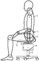
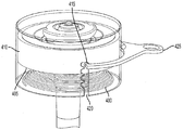
도 1은 본 발명에 의한 저항성 운동 지지기구를 결합한 의자에 앉아있는 사용자를 도시한다.
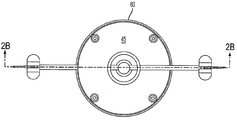
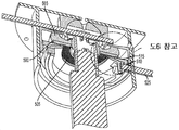
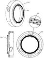
도 2A 및 2B 는 본 발명의 실시예에 따른 저항성 운동 지지기구의 평면도 및 단면도이다.
도 3A 및 3B 는 본 발명의 일 양태에 의한 저항가변수단 단면도 및 측면도이다.
도 4A 및 4B 는 본 발명의 다른 양태에 의한 저항가변수단 단면도 및 측면도이다.
도 5A 및 5B 은 본 발명의 일 양태에 의한 잠금수단 평면도 및 단면도이다.
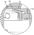
도 6A 및 6B 는 잠금수단이 잠금 및 해제 위치에 있을 때의 도 5B 의 일부에 대한 상세도이다.
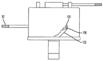
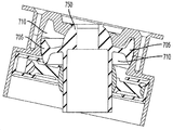
도 7A 및 7B 는 대안적 잠금수단이 해제 및 잠금 위치에 있을 때의 단면도이다.
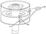
도 8 은 본 발명의 다른 실시예에 따른 저항성 지지기구 사시도이다.
도 9A 및 9B 는 본 발명의 다른 실시예에 따른 평면도 및 단면도이다.
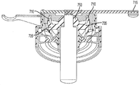
도 10A, 10B, 및 10C 는 높이조절수단을 포함한 본 발명의 다른 실시예에 의한 평면도, 단면도 및 분해도이다.
도 11 및 12 는 도 5의 잠금수단 요소들 상세도이다.
도 13A 및 13B 는 본 발명에 의한 경사 운동을 수행하는 의자를 도시한 것이다.Embodiments will be described below with reference to the accompanying drawings by way of example only:
1 illustrates a user sitting in a chair incorporating a resistance exercise support mechanism according to the present invention.
2A and 2B are a plan view and a cross-sectional view of a resistive motion support mechanism according to an embodiment of the present invention.
3A and 3B are cross-sectional views and side views of a resistance variable stage according to an aspect of the present invention.
4A and 4B are cross-sectional and side views of a resistance variable stage according to another embodiment of the present invention.
5A and 5B are a plan view and a sectional view of the locking means according to an aspect of the present invention.
6A and 6B are detailed views of a portion of FIG. 5B when the locking means are in the locked and unlocked positions.
7A and 7B are sectional views when the alternative locking means are in the unlocked and locked positions.
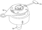
8 is a perspective view of a resistance support mechanism according to another embodiment of the present invention.
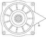
9A and 9B are a plan view and a sectional view according to another embodiment of the present invention.
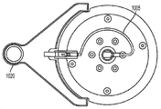
10A, 10B, and 10C are a plan view, a sectional view, and an exploded view according to another embodiment of the present invention including height adjusting means.
11 and 12 are detailed views of the locking means elements of FIG. 5.
13A and 13B illustrate a chair for performing the tilt motion according to the present invention.
이하 설명되는 본 발명의 바람직한 실시예들은 운동 지지기구 및 저항성 운동 지지기구라고도 상호 교환적으로 언급되는 저항성 지지를 제공하는 운동 지지기구를 교시한다. 바람직한 실시예에서, 본 발명은 사무실 의자와 같은 의자에 사용된다. 본원에 기재된 저항성 지지기구는, 사용자가 계속적으로 볼의 회전운동에 반대작용을 함으로써 시트에 앉은 사용자의 중심근력을 강화시키고 골반 및 척추 관절을 동원하여 예를들면 연질 지지조직의 수축 및 위축을 방지하고 실질적으로 이들 관절 주위에 있는 관련 지지근조직의 지구력을 향상시켜 만성적인 정적 착좌 (sitting)로 인한 잠재적 요통 및 손상을 방지하는데 추가적인 이점을 제공하다. 계속적인 움직임 및/또는 동적 운동을 일으키는 이러한 성능으로 혈액순환 개선에 도움이 될 뿐 아니라, 착좌 압력을 분배시켜 사용자의 착좌 안락감과 직접 연관되는 압력점들을 감소시킬 수 있다. Preferred embodiments of the present invention described below teach an exercise support mechanism that provides a resistive support, also referred to interchangeably as an exercise support mechanism and a resistive exercise support mechanism. In a preferred embodiment, the present invention is used in a chair, such as an office chair. The resistive support mechanism described herein reinforces the central muscle of the user sitting on the seat by continually counteracting the rotational movement of the ball and mobilizes the pelvic and spinal joints to prevent, for example, contraction and atrophy of the soft support tissue. And substantially improves the endurance of the associated supportive muscle tissue around these joints, providing additional benefits in preventing potential back pain and damage due to chronic static sitting. This ability to cause continuous movement and / or dynamic movement not only helps improve blood circulation, but can also distribute the seating pressure to reduce pressure points that are directly associated with the user's seating comfort.
또한 본 발명의 일부 실시예들에 의하면 사용자는 저항을 증감시키거나 또는 원하는 위치에서 시스템을 잠금으로써 이러한 움직임을 제한할 수 있다. 예를들면, 이러한 바람직한 자세는, 사용자 무릎이 엉덩이보다 낮아지도록 착좌하여 골반을 더욱 곧게 세우고 척추가 자연스럽게 펴지고 균형을 이룰 수 있는 자세일 수 있다. 또한 고정 높이에서는 척추가 더욱 곧게 세워져야 척추 균형 및 정렬, 통증 및 손상을 피할 수 있지만 본 발명에 의하면 경증 내지 중증의 정형외과적 비정상 신체는, 예를들면, 엉덩이 일측이 타측보다 더욱 낮게 수용하여 척추를 세울 수 있다. 또한 이러한 특징부들은 유사한 골반 불균형 자세를 유발할 수 있는 지갑과 같이 적당한 골반 위치에 영향을 주는 다른 인자들을 수용하는데 유리하게 적용될 수 있다.Further, according to some embodiments of the present invention, the user can limit this movement by increasing or decreasing the resistance or locking the system at a desired position. For example, this preferred position may be a position in which the user's knees are lower than the hips so that the pelvis is straightened and the spine is naturally stretched and balanced. In addition, at the fixed height, the spine should be upright to avoid spinal balance and alignment, pain, and damage, but according to the present invention, a mild to severe orthopedic abnormal body, for example, receives one side of the hip lower than the other. The spine can stand up. These features can also be advantageously applied to accommodate other factors that affect proper pelvic position, such as a wallet, which can cause similar pelvic imbalance postures.
또한, 본원에 기재된 운동 지지기구는 다른 착좌 기구들, 예를들면 치과의사 의자, 실험실 의자, 카시트, 게임용 의자, 레저용 의자 예를들면 술집 의자, 놀이공원 놀이기구, 초등학생 의자 및 사용자에게 저항성 지지를 제공하면 유익할 수 있는 유사한 장치들에 적용될 수 있다. 기타 적용 분야로는 기립 자세에 있는 사용자를 지지하는 장치들, 예를들면 건설현장 지지면들 또는 받침대를 포함한다. 위생사 의자를 사용하는 치과 위생사의 경우, 예를들면, 사용자가 업무를 수행하면서도, 운동 지지기구에 의해 시트 이동이 없으므로 사용자 허리 아래를 통한 힘의 가속이 방지되어, 고정 높이의 시트 표면에 앉아있을 때 경험할 수 있는 사용자 고통 및 손상을 일으키는 이러한 움직임과 관련된 잠재적 긴장이 감소된다.In addition, the athletic support devices described herein are resistant to other seating devices, such as dentist chairs, laboratory chairs, car seats, gaming chairs, leisure chairs such as pub chairs, amusement park rides, elementary school chairs and users. Providing may apply to similar devices that may benefit. Other applications include devices that support the user in an upright position, such as construction site support surfaces or pedestals. In the case of a dental hygienist using a hygienist chair, for example, while the user is performing a task, there is no seat movement by the exercise support mechanism, thus preventing the acceleration of the force under the user's waist, so that they can sit on a fixed height seat surface. The potential tension associated with these movements is reduced when it causes user pain and damage that may be experienced.
도 1을 참조하면, 사용자 (10)가 의자 (15)에 앉아있다. 의자 (15)는 시트부 (20), 등받이 (25), 베이스 (30), 및 하우징 (60) 내부에 본 발명에 의한 저항성 지지기구 (40) (도 1에서 미도시)를 포함한다. 하우징 (60) 상부에 시트부 (20)와의 사이에 시트를 부착시키는 계면 (45)이 제공된다. 도 2A는 하우징 (60) 및 계면 (45)의 평면도이다. 계면 (45)은 의자 시트를 하우징에 장착시키도록 구성되고, 달리 장착면으로 언급된다. 의자 (15)는, 제한적이지 않지만 높이조절기구, 팔걸이, 및 달리 본원에 기재된 저항성 지지기구와 무관한 여러 기타 조절장치들을 포함하여 본 분야에 공지된 다양한 요소들을 포함할 수 있다. 명백하도록, 이하 설명에서는, 수직축은 베이스 (30) 원통축과 일치하는 축을 의미한다. 수평축은 수직축에 수직한 축을 의미한다. 또한, 경사 및/또는 회전운동은 통상적인 의미이고, 경사운동은 수평축 주위로의 회전을 의미하고 회전운동은 수직축 주위로 회전하는 것을 언급하는 것이다. 또한 상세한 설명은 발명 구현에 필요한 요소들을 추가로 기재하고 본 발명에 의해 고려되는 바람직한 실시예를 제시한다. 그러나, 본 발명에 의한 기구 또는 의자를 조립하기 위하여 사용될 수 있는 다양한 하드웨어 및 통상의 기계 요소들은 설명되지 않을 수 있고 본 분야의 기술자 능력 범위에서 고려된다. 도 13A 및 13B는 본 발명의 저항성 지지기구 (40)가 제공하는 2-자유도 운동을 보이는 의자 (15)를 도시한 것이다.Referring to FIG. 1, a
도 2B를 참조하면, 본 발명에 의한 일 예시적 저항성 지지기구가 도시되고, 장착면 (45) 및 베이스 (30)에 연결되는 지지베어링 (50)을 포함한다. 지지베어링 (50)은 베이스 (30)에 대한 장착면 (45)의 경사 및 회전운동 중 하나 또는 양자가 가능하게 한다. 베이스 (30)는 지지베어링 (50) 내부로 마찰 맞춤되는 턱부 (32)를 포함하여, 베이스 (30)는 지지베어링 (50)에 대하여 운동하지 않는다. 장착면 (45)은 지지베어링 (50)에 대하여 경사 또는 회전이 자유롭고 따라서 지지베어링 (50)은 베이스 (30)에 대한 장착면 (45)의 하나 이상의 회전 또는 경사 운동을 가능하게 한다. 하우징 (60)은 장착면 (45)을 지지하는 주 몸체이고, 바람직하게는 이격 유지체 (stand-off)를 포함하여 시트 표면을 기구에 고정시키고 바람직하게는 저항성 지지기구의 모든 또는 대부분의 요소들을 내부에 포함한다. 바람직하게는, 또한 하우징 (60)은 지지베어링 (50)의 최소한 일부를 수용하는 베어링면 (75)을 포함한다. 지지베어링 (50) 및 베어링면 (75)의 표면들은 최소 마찰력이 이들 사이에 존재하도록 제공되어 지지베어링 (50)에서의 운동은 상대적으로 방해되지 않는다. 하우징 (60)은 바람직하게는 장착면 (45)에서 직접 연장되고 일체로 형성된다. 베어링 및 베어링면의 기능은 본 분야에서 일반적으로 공지되어 있고 본원에서 더욱 상세하게 설명되지 않는다. 또한 본 발명은 지지베어링 (50) 및 베어링면 (75)에 의해 형성되는 완전한 2-자유도 운동을 제공할 수 있는 베어링 및 베어링면에 대한 기능적 대안의 적용도 고려한다.Referring to FIG. 2B, an exemplary resistive support mechanism according to the present invention is shown and includes a support bearing 50 connected to the mounting
선회볼 (55)은 베이스 (30) 일부에 배치된다. 하기되는 바와 같이, 선회볼 (55)은 기구에 저항성 지지를 제공하기 위하여 작용하는 저항력 제공수단을 가진다. 다양한 방식의 저항력 제공수단 구현이 고려된다. 저항력 제공수단은 바람직하게는 선회볼 (55)에 작용하는 저항 카트리지 (40) 방식으로 구현된다. 이러한 방식에서, 저항력 및/또는 감쇠력은 장착면 (45)의 수직평면에 수직하게 인가되어 선행 장치들과 비교하여 더욱 안정하고 제어된 안착이 가능하다. 예를들면, 전술된 Thole 특허는 탄성재료가 다양한 압축력 및 토크를 가하도록 구성되어 탄성재료에 여러 압축력 및 토크가 인가된다.The
도 2B의 실시예에서, 저항 카트리지 (40)는 베이스 (30)에 대하여 경사 및/또는 회전 운동하고 저항 카트리지 (40) 및 이에 따라 장착면 (45)이 베이스 (30)에 대하여 상대 운동할 때 베이스 (30)에 저항력을 인가하도록 장착면 (45)에 고정 연결된다. 저항 카트리지 (40)는 본 발명의 저항성 지지기구에 있어서 핵심 기능을 제공한다. 본 실시예에서, 저항 카트리지 (40)는 내부에 탄성부재 (65b), 선회볼 (55), 및 카트리지 하우징 (70)을 포함한다. 탄성부재 (65b)는 연장부재 (65a)를 통하여 선회볼 (55)과, 그리고 저항성 카트리지의 카트리지 하우징의 (40)의 벽 (70)과 접촉되도록 구성되어, 작동에 있어서, 탄성부재 (65)는 저항 카트리지 (40) 및 선회볼 (55) 간의 상대운동에 의해 압축된다. 바람직하게는, 선회볼 (55)은 연장부재 (65a)와의 접합 활주 계면을 가진다. 장착면 (45)이 기울어지면, 탄성재료 (65b)는 벽 (70)과 연장부재 (65a) 사이에 압축된다. 바람직하게는, 연장부재 (65a)는 강성재료로 형성되고 선회볼 (55) 주위 링을 형성하고 벽 (70)을 향해 방사방향으로 연장된다. 연장부재 (65a) 및 선회볼 (55) 간의 활주 계면으로 인하여 장착면 (45) 전체가 기울어질 수 있고 탄성부재 (65b)는 장착면 (45)의 비구속적 운동을 방지하는 감쇠 특성을 제공하고, 운동의 전 범위에 걸쳐 유연한 운동을 가능하게 하여 장착면 (45) 및 이에 부착된 임의의 대상체 예를들면 (도 1의) 시트 (20)에 저항성 지지를 제공한다.In the embodiment of FIG. 2B, the
탄성부재 (65b)는 바람직하게는 탄성링, 실리콘, 젤, 일련의 고무요소들, 및 압축 또는 달리 힘을 받을 때 감쇠 특성을 가지거나 달리 상대운동에 저항할 수 있는 재료로 알려진 임의의 유사 재료들로 이루어진 군에서 선택된다. 또한 탄성부재들의 조합이 적용되어 잠재적 운동 범위에서 인가되는 저항을 가변시킬 수 있다. 예를들면, 탄성부재 (65b)는 연장요소 (65a)와 접촉하는 제1 탄성부재 및 벽 (70)과 접촉하는 제2 탄성부재를 포함할 수 있다. 본 발명의 바람직한 실시예에서, 탄성부재 (65b)는 벽 (70) 및 연장요소 (65a)에 결합되는 점탄성재료이다. 점탄성재료를 사용하면 재료 변형이 있는 곳에 감쇠효과를 제공하고 압축될 때 더 많은 하중을 흡수하고 분배하며 하중이 제거될 때 서서히 회복된다. 이러한 결과, 저항성 지지기구 (40)가 원 위치로 복귀할 때, 원 위치 복귀 운동은 재료 특성에 기초하여 감쇠되고 제어된다. 점탄성재료를 사용하면 저항속도가 강조되고 탄성부재 유동 특성이 더욱 뚜렷하므로 감쇠가 더욱 증가된다. 즉, 점탄성재료는 하중이 인가될 때 점성 및 탄성 특정 모두를 보이는 반응을 하고 따라서 이력 현상이 관찰된다.
저항 카트리지 (40)의 벽 (70)은 하우징 (60) 내부에서 수직 활주할 수 있는 외면을 포함하고, 이에 따라 저항 카트리지 (40)는 하우징 (60) 내에서 수직 위치로 정렬되며, 이하 더욱 상세히 설명된다. 바람직한 실시예에서, 탄성부재 (65b)는 점탄성링이고, 연장요소 (65a)는 선회볼 (55)과 관절을 이루고 감쇠특성을 가지는 탄성부재 (65b)를 압축하도록 방사방향으로 외향 연장되는 링 형태의 강성재료이다. 또한 서로들 및/또는 연장부재 (65a) 선단과 접촉하는 다수의 젤들을 포함하는 제2 탄성부재가 제공될 수 있다. 다수의 젤들이 포함되면, 비록 본 발명의 범위에서 변형들을 고려할 수 있지만, 바람직하게는 선회볼 (55)에서 원위의 젤들은 선회볼 (55)의 근위 젤들보다 밀도가 더 높다. 이러한 구성으로 경사각이 증가할수록 경사에 대한 저항이 더욱 커진다.The
또한, 본원에 기재된 탄성부재들 (65)이 제공되면 장착면 (45) 및 여기에 장착된 시트 (20)는 탄성부재들 (65) 압축-전 경사 또는 회전이 없는 원위치로 편향된다. 따라서, 의자에 앉은 사용자가 일 방향으로 기울이면 상기와 같이 저항성 지지기구에 의해 지지되지만, 이후 기립하면, 시트는 비-편향 원위치로 복귀된다.Further, provided with the elastic members 65 described herein, the mounting
본 발명의 일 양태에 의하면, 선회볼 (55)에 작용하는 저항력 가변수단이 제공된다. 이에 따라 저항성 카트리지에 의해 인가되는 저항은, 예를들면, 저항성 지지기구의 의도적 적용 또는 사용자에 따라 증감된다. 의자의 경우, 덩치가 큰 사람은 작은 사람보다 더 큰 저항력이 필요하다. 또한, 덩치와 무관하게, 사용자는 적당한 저항을 원할 수 있고, 즉 이에 따라 운동효과를 볼 수 있도록 중심근육에 영향을 줄 수 있고 골반 및 척추 관절을 더욱 움직일 수 있고 및/또는 예를들면 치과위생사 작업과 같이 사용자가 달리 반복적으로 움직여야 할 필요가 있을 때 착좌 지지 연조직 및 관절에 미치는 힘을 줄일 수 있는 적당한 저항을 원할 수 있다. 예시된 도 2B의 실시예에서, 저항력 가변수단은 하우징 (60) 바닥면 (85) 및 저항 카트리지 (40) 하면 (95) 사이에서 압축되는 스프링 (80)을 포함한다. 인가되는 힘을, 따라서 저항 카트리지에서의 저항력을 가변시키기 위하여, 바람직하게는 계면판 (95)에 기능적으로 부착되는 저항레버 (90)가 제공된다. 저항레버 (90)는 스프링 (80) 압축을 받는 계면판 (95) 위치, 이에 따라 베이스 (30)에 대한 저항성 카트리지 (40) 위치를 변경시키도록 이동된다. 본 분야의 기술자에 의해 이해될 수 있는 바와 같이, 베이스 (30)에 대한 저항 카트리지 (40) 위치, 즉 작용하는 베이스 (30)에 작용되는 저항 카트리지 (40)의 높낮이는, 경사/회전점이 고정되므로, 저항 카트리지 (40)에 의해 인가되는 유효한 저항력을 결정한다. 즉, 선회볼 (55) 및 지지베어링 (50) 사이 유효 거리는 저항 카트리지 (40)에 의해 인가되는 저항력을 결정한다. 도 3A 및 3B를 참조하면, 스프링 (80) (설명을 위하여 도시되지 않음)은 저항 카트리지 (40) 하면 (95) 및 하우징 (60) 내의 이에 일체된 모든 부품들을 나선 (102) 내의 잠금핀 (100) 위치로 표시되는 최상의 수직 위치로 편향시킨다. 본 실시예에서, 나선 (102) 계단을 따르는 핀 (100) 위치는 나선 (102) 단계 내에서 저항레버 (90)를 이동시켜 조절안장 (108)에 의해 고정될 수 있다. 나선 (102)은 저항 카트리지 (40) 양측에 제공되고, 일측에는 레버 (90)를 이동시키기 위한 계단을 포함하고 타측에는 계단 내에서 고정되도록 핀 (100)이 제공되는 상응 계단을 포함한다는 것을 이해하여야 한다. 핀 (100)이 나선 (102) 내 더 낮은 계단에 있을 때, 저항 카트리지 (40)가 회전/경사점으로부터 더 멀어지므로, 시스템 내의 저항이 더 크다는 것을 본 분야의 기술자는 이해할 것이다.According to one aspect of the present invention, a variable resistance force acting on the
본 발명의 다양한 기타 구현들 및 실시예들이 하기되지만, 작동 원리는 지지베어링 및 선회볼이 상기와 같이 제공된다는 것이다. 또한, 바람직하게는 탄성재료가 작용하는 선회볼 및 지지베어링 사이 거리를 변경시키는 저항력 가변수단이 제공된다. 이제 도 4A 및 4B를 참조하면, 저항력 가변수단의 변동을 보이고 여기에서 스프링 (400)은 카트리지 하우징 (410) 하면 (405)에 작용하여 카트리지 하우징 (410)을 도 3을 참조하여 기재된 바와 유사한 방식으로 최상의 위치로 편향시킨다. 본 실시예에서는, 그러나 카트리지 하우징 높이는 일련의 계단 (420) 내에서 레버 정지구 (415) 위치에 따라 제한된다. 레버 정지구 (415)가 소망 계단 (420)에 안착되도록 레버 (425)를 이동시킨다. 따라서, 스프링 (400)은 상향력을 저항 카트리지 (440)에 가하고 저항 카트리지 (440)는 레버 정지구 (415)가 놓이는 일련의 계단 (420) 에서 특정한 계단에 의해 제한되는 위치에 놓인다.While various other implementations and embodiments of the present invention are described below, the principle of operation is that support bearings and pivot balls are provided as above. Further, preferably, variable resistance means for changing the distance between the pivoting ball and the support bearing on which the elastic material acts is provided. Referring now to FIGS. 4A and 4B, a variation of the resistance variable means is shown wherein the
본 발명의 다른 양태에 의하면, 베이스에 대하여 장착면 (45)이 운동하는 임의의 저항 카트리지 (40) 위치로의 잠금수단이 더욱 제공된다. 이러한 잠금수단은 시트 또는 장착면 (45)에 장착된 기타 장치들을 일정 위치에서 잠그고, 이에 따라 기구가 원 위치로 복귀되는 것을 방지하는 이점들을 제공한다. 본원에 기재된 상이한 예시들의 잠금수단은 소정의 증분 위치 또는 자유 부동 위치로 잠근다. 잠금수단을 제공함으로써 저항성 기능이 활성되는 것이 언제나 유익하지 않거나 달리 사용 중 저항성 지지기구가 임의의 경사 또는 회전 위치에 감기는 것이 추가적인 기능을 제공하는 경우에 특히 유리하다.According to another aspect of the present invention, there is further provided a locking means to any position of the
도 5A, 5B 및 6A, 6B를 참조하면, 본 발명에 의한 예시적 잠금수단이 도시된다. 본 실시예의 저항성 지지기구는 저항성 카트리지 내부에 강성판 (500)을 포함하고 이는 연장부재 (565) 하면에 배치된다. 강성판 (500)은 연장부재 (565)와의 접촉면적 원위 표면에 다수의 잠금요소들 (505)을 가지는 표면을 포함한다. 저항성 지지기구를 위치에 잠그기 위하여, 상보적 잠금요소들 (535) (도 12에 도시) 표면을 가지는 잠금패드 (510)가 제공되어 강성판 (500) 다수의 잠금요소들 (505)와 접촉된다. 잠금요소들 (505)이 상보적 잠금요소들 (535)와 체결되면, 추가적인 경사 및/또는 회전운동이 억제된다. 다수의 잠금요소들 (505)을 가지는 강성판 (500)의 예시는 도 11에 도시된다. 도시된 실시예에서, 다수의 잠금요소들 (505)는 도시된 바와 같이 강성판 하면에 깔주기 표면 (530)으로 제공된다. 상응하는 잠금패드 (510)는 도 12에 도시되고, 봉우리형의 깔주기부 (535)를 가지며 이는 강성판 (500) 깔주기 표면 (530)과 접촉되고 해제된다. 잠금요소들로서 기술된 표면들은 유사한 잠금 특성을 제공하는 다양한 대안적 형상 및 재료 및 조합들을 더욱 포함할 수 있다. 상기된 바와 유사한 방식으로 사용될 수 있는 대안적 잠금패드 및 잠금요소들의 예시로는 3M™에서 상표명 Dual Lock™로 판매되는 재밀폐성 파스너라고 언급되는 것들이다.5A, 5B and 6A, 6B, exemplary locking means in accordance with the present invention are shown. The resistive support mechanism of this embodiment includes a
고려될 수 있는 기타 잠금수단은 자전거 디스크 브레이크, 다층 압축판 및 로터 및 패드을 포함하고, 이들 모두는 바람직하게는, 본원의 여러 실시예들에서 사용될 수 있는 소정의 증분식 또는 무작위 체결점들로 작동되는 잠금수단와 유사한 방식으로 적용될 수 있다.Other locking means that may be considered include bicycle disc brakes, multilayer compression plates and rotors and pads, all of which preferably operate with certain incremental or random fastening points that may be used in the various embodiments herein. It can be applied in a similar manner to the locking means.
다시 도 5B를 참조하면, 예를들면, 캠기구를 작동시키는 비틀림 운동으로 잠금패드 (510)를 상하강시켜 잠금패드 (510)의 상보적 잠금요소들 (535)을 강성판 (500)의 깔주기 표면 (530)과 접촉시키거나 떼어낼 수 있는 제동레버 (525)가 제공된다. 도 12의 상세도를 참조하면, 제동레버 (525)를 이러한 방식으로 상하강시키는 수단의 일 예시로는 제동레버 (525)와 마찰 끼워맞춤할 수 있는 크기 또는 달리 치수의 유각 슬롯 (540)을 제공하는 것이다. 제동레버 (525)를 상향 활주 경동하면 잠금패드 (510)를 깔주기 표면 (530)과 접촉시킬 것이고, 제동레버 (525)를 하향 활주 경동하면 잠금패드 (510)를 깔주기 표면 (530)으로부터 해제시킬 것이다. 제동레버 (525)의 우연한 이동을 방지하도록 작동 중에 인가되는 힘보다 더 크고 제동레버 작동에 있어서 최소한의 힘이 필요하도록 슬롯의 각도 및 슬롯 및 제동레버 (525)의 치수가 결정된다.Referring again to FIG. 5B, for example, the
따라서 저항 카트리지, 및 선택적으로 저항가변수단 및 특정 위치로의 운동 지지기구 잠금수단을 포함한 본 발명의 바람직한 실시예를 설명하였고, 다양한 대안들을 이후 기술할 것이다. 특히, 본 대안들은 대안적 저항가변수단 및/또는 운동 지지기구 잠금수단에 관한 것이다. 본 분야의 기술자들은 기재된 조합에서의 저항 카트리지, 저항가변수단 및 잠금수단의 예시들의 특정 조합들로 본 발명이 제한되지 않는다는 것을 이해할 수 있을 것이다. 본원에 기재된 저항 카트리지, 저항가변수단, 및 잠금수단의 조합들이 본원에서 고려되고, 명세서 말미의 특허청구범위에 의해서만 한정된다. 이하 상세한 설명에서, 상기와 공통적인 요소들은 상세히 설명되지 않고 이들의 작동은 본 분야의 기술자에게 명백할 것이다.Thus, a preferred embodiment of the present invention has been described, including a resistance cartridge and, optionally, a resistance variable stage and movement support locking means to a specific position, and various alternatives will be described later. In particular, the alternatives relate to alternative resistance variable stages and / or movement support locking means. Those skilled in the art will appreciate that the present invention is not limited to the particular combination of examples of resistor cartridge, resistor variable stage and locking means in the described combination. Combinations of resistance cartridges, resistance variable stages, and locking means described herein are contemplated herein and are defined only by the claims at the end of the specification. In the following detailed description, elements common to the above are not described in detail and their operation will be apparent to those skilled in the art.
이제 도 7A 및 7B를 참조하면, 본 발명의 일 실시예가 도시되며, 여기에서 지지베어링 (750)은 하나, 및 바람직하게는 두 개의 베어링 돌출부 (705)를 포함한다. 저항 카트리지는 바람직하게는 베어링 돌출부 (705)와 접촉영역을 제공하고 잠금수단이 작동될 때 돌출부 (705)와 마찰 맞춤 접촉되는 상응 잠금표면들 (710)을 포함한다. 잠금 작동을 위하여, 조절레버 (715)가 제공되어 운동이 잠기는 위치로 저항 카트리지를 변위시킨다. 베어링 돌출부 (705)를 회전시켜 잠금표면들 (710)와 접촉시키도록 조절레버 (715)에 회전운동이 인가된다. 도 8은 본 실시예에 의한 저항 카트리지를 보인다. 레버 (715)를 대략의 수평축 주위로 돌려 레버 (715)를 움직이고, 그후 대략 수평축 주위로 돌려 상기된 잠금 특징부들과 체결시킨다. 이러한 방식으로, 잠금기구 즉 레버 (715)는 사용자가 필요하다면 수평축 주위로 회전시켜 작동 및 해제되고, 수직축 주위로 회전시켜 잠글 수 있다. 또한 도 8에는, 상기된 바와 같이 운동 지지기구에서 저항력을 가변시키기 위하여 저항 카트리지가 작용하는 베이스 (725) 위치를 변경시키기 위하여 저항 카트리지를 상하강하는 힘 조절레버 (720)가 도시된다. 실제로, 도 7 및 8에 대하여 기술되고 도시되는 잠금수단은 지지베어링 주위로 약 +/- 14˚의 최대 경사 범위를 가질 수 있다.Referring now to FIGS. 7A and 7B, one embodiment of the present invention is shown, wherein the support bearing 750 includes one, and preferably two bearing
본 발명에 의한 저항성 지지기구를 약 14˚의 경사 범위로 적용하면 운동 범위를 극대화하고 안전을 고려한 합리적인 한도에서 효과적인 관절 동원 효과가 있다는 것을 알았다.When the resistance support mechanism according to the present invention is applied in the inclination range of about 14 °, it was found that there is an effective joint mobilization effect at a reasonable limit considering the safety and maximizing the range of motion.
이제 도 9A 및 9B를 참조하면, 본 발명에 의한 다른 잠금수단의 실시예가 도시된다. 도 9A 및 9B의 잠금수단은 저항 카트리지 (910) 상부에 위치하는 잠금회전볼 (905)을 포함한다. 잠금회전볼 (905)은 본원에 기재된 선회볼과 같이 제공되고 본 발명의 운동 지지기구가 주위로 경사 및/또는 회전된다. 잠금회전볼 (905)과 마찰 접촉되도록 하부 잠금표면디스크 (915)가 제공된다. 이것은 하우징 몸체 (925)와 접촉 또는 해제시키도록 잠금몸체 (920)를 상하강하여 잠금몸체 (920) 및 하우징 몸체 (925) 사이 오프셋 거리를 제공함으로써 달성된다. 또한 이러한 운동은 하중을 회전 디스크 (915)의 최상측 (940) 상의 잠금몸체 (935) 하면에 있는 잠금표면 (930)으로 전달한다. 표면들 (930, 940)은 동심 리지들을 가지고 추가적인 잠금력을 제공한다. 이들 표면은 서로 접촉될 때 변형되는 고무 파지층을 포함하여 추가적인 잠금력을 제공한다. 잠금레버 (950) 가 제공되어 락을 체결하고 해제한다. 이러한 잠금작용은 예를들면, 잠금레버 (950)를 수직축 주위로 돌려 잠금몸체 (920)는 락과 체결되거나 해제되도록 수직 변위됨으로써 달성된다.Referring now to Figures 9A and 9B, an embodiment of another locking means according to the present invention is shown. The locking means of FIGS. 9A and 9B includes a locking
도 10A, 10B 및10C를 참조하면, 장착면 (1045) 및 베이스 (1030)와 연결되는 지지베어링 (1050)을 포함하는 또 다른 본 발명의 실시예가 도시된다. 지지베어링 (1050)으로 인하여 베이스 (1030)에 대한 장착면 (1045)의 경사 및 회전운동의 하나 또는 양자가 가능하다. 베이스 (1030)는 지지베어링 (1050)에 대하여 운동하지 않는다. 따라서 장착면 (1045)은 지지베어링 (1050)에 대하여 자유로이 기울여지거나 회전되어 지지베어링 (1050)은 베이스 (1030)에 대한 하나 이상의 장착면 (1045) 회전 및 경사 운동을 가능하게 한다. 이격 유지체 (1046)를 포함하고 의자 표면을 기구에 고정시키는 장착면 (1045)에서 연장되는 하우징 (1060)은 바람직하게는 저항 카트리지 (1040) 내부의 모든 또는 대부분의 저항성 지지기구 요소들을 내부에 포함하도록 제공된다. 바람직하게는, 또한 하우징 (1060)은 지지베어링 (1050)의 최소한 일부를 수용하는 베어링면 (1075)을 포함한다.10A, 10B, and 10C, another embodiment of the present invention is shown that includes a
저항 카트리지 (1040) 내부의 선회볼 (1055)은 베이스 (1030) 일부에 배치된다. 상기 실시예들에 대하여 설명된 바와 같이, 선회볼 (1055)이 작용하는 베이스 (1030) 위치를 조절함으로써 가변되는 선회볼 (1055) 및 지지베어링 (1050) 사이 거리로 인하여 인가되는 저항이 가변된다. 연장요소 (1063)는 선회볼 (1055)로부터 연장되는 강성 요소이고 탄성부재 (1065)가 작용한다. 도시된 바와 같이, 탄성부재 (1065)는 연장요소 (1063) 및 저항 카트리지 (1040) 벽 사이에서 압축되어 경사 및/또는 회전에 대한 저항을 제공한다.The
본 실시예에서, 베이스 (1015)에 대한 저항 카트리지 (1010)의 저항 운동을 받는 장착면 상부의 시트, 또는 기타 표면 위치를 상승 또는 하강시키는 케이블 (1005)이 제공된다. 레버 (1020)를 수직축 주위로 돌려 작동시키면 케이블 (1005)이 당겨진다. 케이블 (1005)은, 도시된 바와 같이, 케이블관 내에 제공되어 케이블에 대한 손상이 방지된다. 본 발명에 의하면, 수직축 주위로 레버 (1020)를 돌리면 케이블 (1005)이 풀리거나 당겨져 베이스 (1015) 상부의 공기실린더를 작동시키고, 이 결과 실린더는 상승 또는 하강된다. 다양한 기타 하드웨어 요소들이 도시되지만 이들은 장착을 용이하게 하거나 본 발명의 전기 실시예들에 대하여 설명되었으므로 기술되지 않는다.In this embodiment, a
상기 실시예들은 본 발명의 예시들이고 하기 첨부된 청구범위에 의해서만 정의되는 본 발명의 범위로부터 벗어나지 않고 본 분야의 기술자에 의한 변형 및 변형이 가능하다. 상기 저항 카트리지 내의 탄성링 또는 젤들을 제공하기 위해 다양한 재료들이 적용될 수 있다. 또한, 이러한 재료들 외에도 감쇠 및/또는 저항 특성을 제공하는, 예를들면, 스프링과 같은 다른 수단들도 고려될 수 있다. 또한, 기타 인가저항가변수단이 고려될 수 있다. 본원에 기재된 현재 바람직한 실시예들은 본 발명의 예시로 고려되어야 한다. 유사하게, 또한 기타 본 발명의 지지기구 잠금수단이 고려된다.The above embodiments are examples of the invention and modifications and variations are possible by those skilled in the art without departing from the scope of the invention as defined only by the appended claims. Various materials can be applied to provide the elastic ring or gels in the resistance cartridge. In addition to these materials, other means, such as springs, which provide damping and / or resistance properties may also be considered. In addition, other applied resistance variable stages may be considered. The presently preferred embodiments described herein are to be considered as illustrative of the invention. Similarly, also other support mechanism locking means of the present invention are contemplated.
사용자 무게 중심 바로 밑 또는 가까이 지지베어링을 배치하면 선행 기구들과 비교하여 사용자의 관절들에 더욱 효과적으로 영향을 줄 수 있는 예기치 못한 이점들을 제공한다는 것을 알았다. 능동적 좌석 구조의 선행기술은 사용자로부터 더욱 떨어진 선회점들을 가지고, 이에 따라 중요한 관점을 동원하기보다는 사용자의 신체 전체가 더욱 기울어진다.It has been found that placing support bearings directly below or near the user's center of gravity provides unexpected advantages that can more effectively affect the user's joints compared to prior instruments. The prior art of active seating structures has turning points further away from the user, thus tilting the entire body of the user rather than mobilizing an important point of view.
Claims (26)
베이스에 대한 장착면의 경사 및 회전 운동 중 하나 또는 양자를 가능하게 하고 장착면 및 베이스에 연결되는 지지베어링;
베이스 일부에 기능적으로 부착되는 선회볼; 및
장착면이 상기 회전 및 경사 운동 중 하나 또는 양자를 수행할 때 베이스에 대한 운동을 수행하며 저항력을 베이스에 인가하고 장착면에 고정 연결되는 저항 카트리지로 구성되며, 상기 저항 카트리지는,
카트리지 하우징; 및
탄성부재를 포함하고 탄성부재는 상기 선회볼 및 상기 하우징 벽과 접촉되어 상기 저항 카트리지 및 상기 선회볼 사이 상대 운동으로 압축되어 장착면에 대한 저항성 지지를 제공하는, 저항성 운동 지지기구.A resistive movement support mechanism coupled to a mounting surface and a base, the resistive movement supporting mechanism providing resistive support to the mounting surface when the mounting surface performs one or both of rotational and oblique movements relative to the base,
Support bearings which enable one or both of the tilt and rotational movement of the mounting surface relative to the base and are connected to the mounting surface and the base;
A pivot ball that is functionally attached to a portion of the base; And
A resistance cartridge configured to perform movement relative to the base when the mounting surface performs one or both of the rotational and inclined movements, and to apply a resistive force to the base and to be fixedly connected to the mounting surface, wherein the resistance cartridge includes:
Cartridge housing; And
And a resilient member, the resilient member being in contact with the pivot ball and the housing wall to compress the relative motion between the resistive cartridge and the pivot ball to provide resistive support for the mounting surface.
베이스에 대한 시트의 경사 및 회전 운동 중 하나 또는 양자를 가능하게 하고 시트 및 베이스에 연결되는 지지베어링;
베이스 일부에 고정 부착되는 선회볼; 및
시트가 회전 및 경사 운동 중 하나 또는 양자를 수행할 때 베이스에 대한 운동을 수행하며 저항력을 베이스에 인가하고 시트에 고정 연결되는 저항 카트리지를 포함하고, 상기 저항 카트리지는,
카트리지 하우징; 및 탄성부재를 가지고, 탄성부재는 상기 선회볼 및 상기 하우징의 벽과 접촉되어 상기 저항 카트리지 및 상기 선회볼 사이 상대 운동으로 압축되어 시트에 대한 저항성 지지를 제공하는, 의자.A chair having a seat, a base, and an exercise support mechanism, wherein the exercise support mechanism is coupled to the base and the seat, and the exercise support mechanism is adapted to the seat when the sheet performs one or both of rotational and oblique movements relative to the base. Provide resistance support to the movement support mechanism,
Support bearings which enable one or both of the tilt and rotational movement of the seat relative to the base and are connected to the seat and the base;
A pivot ball fixedly attached to a part of the base; And
A resistance cartridge which performs movement relative to the base when the sheet performs one or both of rotational and oblique movements, and which applies a resistance to the base and is fixedly connected to the seat, wherein the resistance cartridge comprises:
Cartridge housing; And an elastic member, the elastic member being in contact with the pivot ball and the wall of the housing and compressed in a relative motion between the resistance cartridge and the pivot ball to provide resistive support for the seat.
Applications Claiming Priority (5)
| Application Number | Priority Date | Filing Date | Title |
|---|---|---|---|
| US41725810P | 2010-11-25 | 2010-11-25 | |
| US61/417,258 | 2010-11-25 | ||
| US201161475010P | 2011-04-13 | 2011-04-13 | |
| US61/475,010 | 2011-04-13 | ||
| PCT/CA2011/050733 WO2012068688A1 (en) | 2010-11-25 | 2011-11-24 | Resistive support mechanism |
Publications (1)
| Publication Number | Publication Date |
|---|---|
| KR20140035312A true KR20140035312A (en) | 2014-03-21 |
Family
ID=46145331
Family Applications (1)
| Application Number | Title | Priority Date | Filing Date |
|---|---|---|---|
| KR1020137014091A KR20140035312A (en) | 2010-11-25 | 2011-11-24 | Resistive support mechanism |
Country Status (15)
| Country | Link |
|---|---|
| US (1) | US9211013B2 (en) |
| EP (1) | EP2642900B1 (en) |
| JP (1) | JP5917547B2 (en) |
| KR (1) | KR20140035312A (en) |
| CN (1) | CN103298374B (en) |
| AU (1) | AU2011334529B2 (en) |
| CA (1) | CA2816224C (en) |
| DK (1) | DK2642900T3 (en) |
| HK (1) | HK1189142A1 (en) |
| IL (1) | IL226487A0 (en) |
| MX (1) | MX339036B (en) |
| MY (1) | MY158976A (en) |
| SG (1) | SG190365A1 (en) |
| WO (1) | WO2012068688A1 (en) |
| ZA (1) | ZA201303634B (en) |
Cited By (1)
| Publication number | Priority date | Publication date | Assignee | Title |
|---|---|---|---|---|
| US10842275B2 (en) | 2016-12-20 | 2020-11-24 | Kokuyo Co., Ltd. | Chair and cover member of the chair |
Families Citing this family (21)
| Publication number | Priority date | Publication date | Assignee | Title |
|---|---|---|---|---|
| FR2992912B1 (en) * | 2012-07-03 | 2014-07-11 | Renault Sa | SEAT BACK FOLDING DEVICE |
| DE202012010417U1 (en) * | 2012-10-23 | 2012-12-17 | Mey Chair Systems Gmbh | Spring joint module for an industrial chair, industrial chair |
| EP3462986B1 (en) | 2016-05-24 | 2021-06-30 | Engell, Maria Terese | Balance chair |
| DE102016217992A1 (en) * | 2016-09-20 | 2018-03-22 | VS Vereinigte Spezialmöbelfabriken GmbH & Co. KG | seating |
| IT201600108015A1 (en) * | 2016-10-26 | 2018-04-26 | Donati Spa | OSCILLATING SEAT FOR A CHAIR OR AN ARMCHAIR |
| DE102017201360A1 (en) | 2017-01-27 | 2018-08-02 | Dieter Mey | FEATHER MODULE, ESPECIALLY FOR A CHAIR OR STOOL, AND SEATING DEVICE, IN PARTICULAR CHAIR OR STOOL |
| CN107319806A (en) * | 2017-06-29 | 2017-11-07 | 浙江恒林椅业股份有限公司 | Thing to sit on and its inclination rocking equipment |
| WO2019069263A1 (en) * | 2017-10-05 | 2019-04-11 | Godrej & Boyce Mfg. Co. Ltd., | Posture adaptive work chair |
| US10383448B1 (en) | 2018-03-28 | 2019-08-20 | Haworth, Inc. | Forward tilt assembly for chair seat |
| CN108634662A (en) * | 2018-07-19 | 2018-10-12 | 深圳市悠睿科技有限公司 | A kind of seat reclining device |
| JP7091959B2 (en) * | 2018-09-12 | 2022-06-28 | トヨタ自動車株式会社 | Vehicle seat |
| FI128205B (en) | 2018-10-31 | 2019-12-31 | Easydoing Oy | A swing support device for a chair |
| CN109717654A (en) * | 2019-01-09 | 2019-05-07 | 深圳市悠睿科技有限公司 | A kind of chair regulating device of adjustable tilt angle |
| CN109602197A (en) * | 2019-01-17 | 2019-04-12 | 佛山市雅龙五金家具有限公司 | Rotating disk locking structure and turning chair |
| EP3995356B1 (en) | 2020-11-05 | 2024-03-06 | B/E Aerospace, Inc. | Rotary recline mechanism |
| US20220202641A1 (en) * | 2020-12-24 | 2022-06-30 | Steven Reisman | Physical conditioning and therapeutic conditioning pivoting system |
| US11229291B1 (en) | 2021-05-04 | 2022-01-25 | Michael David Collier | Ergonomic motion chair |
| US11825949B2 (en) | 2021-05-04 | 2023-11-28 | Michael David Collier | Ergonomic motion chair |
| JP2023005484A (en) * | 2021-06-29 | 2023-01-18 | トヨタ自動車株式会社 | Chair |
| TWM627702U (en) * | 2021-12-22 | 2022-06-01 | 林長貞 | Swinging seat chassis |
| WO2023121675A1 (en) * | 2021-12-24 | 2023-06-29 | Steven Reisman | Therapeutic and physical conditioning pivoting system |
Family Cites Families (19)
| Publication number | Priority date | Publication date | Assignee | Title |
|---|---|---|---|---|
| GB1012354A (en) | 1963-02-27 | 1965-12-08 | Martin James | Improvements relating to aircraft seat harnesses |
| US5170997A (en) | 1989-11-30 | 1992-12-15 | Hutchinson | Resilient articulation with variable stiffness |
| US5203853A (en) | 1991-09-18 | 1993-04-20 | Herman Miller, Inc. | Locking chair tilt mechanism with torsion bar |
| CH685848A5 (en) | 1993-01-14 | 1995-10-31 | Mobil Werke U Frei Ag | Pendulum chair |
| US5769492A (en) * | 1996-12-10 | 1998-06-23 | Jensen; Robert J. | Back saver sport seat |
| US6174548B1 (en) * | 1998-08-28 | 2001-01-16 | Andrx Pharmaceuticals, Inc. | Omeprazole formulation |
| US6176548B1 (en) | 1998-10-23 | 2001-01-23 | Haworth, Inc. | Tilt mechanism for chair having adjustable spring characteristics |
| US6209958B1 (en) * | 1998-10-23 | 2001-04-03 | Haworth, Inc. | Universal tilt mechanism for a chair |
| IT1308075B1 (en) | 1999-06-04 | 2001-11-29 | Pro Cord Srl | CHAIR WITH OSCILLATING SEAT |
| US6481795B1 (en) | 2000-06-05 | 2002-11-19 | Burl Pettibon | Therapeutic chair |
| WO2004067364A2 (en) * | 2003-01-30 | 2004-08-12 | Probst Paul C | Seat technology |
| US7100983B1 (en) | 2004-12-09 | 2006-09-05 | Gant Richard A | Lumbar flexing seating apparatus |
| DE102005005089A1 (en) * | 2005-02-03 | 2006-08-10 | Josef GLÖCKL | Support element e.g. for seating furniture, has seating element with upright tubular element and base and seating element connected to base by support element so as to be swiveled and reset |
| CA2600310C (en) * | 2005-03-01 | 2014-07-08 | Haworth, Inc. | Tilt control mechanism for a chair |
| JP4989804B2 (en) * | 2005-05-23 | 2012-08-01 | プラス株式会社 | Height-adjustable chair with locking function |
| DE102006021439A1 (en) * | 2005-07-21 | 2007-02-22 | Neubert, Frank, Dipl.-Designer | Swivel system for office chairs comprises ball and socket joint mounted in fixed, vertical, tubular casing, seat being mounted on top of ball shaft, which passes through damper ring |
| US20090230743A1 (en) * | 2007-12-18 | 2009-09-17 | Afrooz Derakhshan | Rehabilative exercising chair |
| WO2010033956A1 (en) | 2008-09-22 | 2010-03-25 | Crown Equipment Corporation | Swivel seat with adjustable swivel resistance |
| US8540314B2 (en) * | 2009-10-28 | 2013-09-24 | Products Of Tomorrow, Inc. | Flex chair |
-
2011
- 2011-11-24 JP JP2013540192A patent/JP5917547B2/en active Active
- 2011-11-24 CA CA2816224A patent/CA2816224C/en active Active
- 2011-11-24 SG SG2013039284A patent/SG190365A1/en unknown
- 2011-11-24 US US13/988,712 patent/US9211013B2/en active Active
- 2011-11-24 CN CN201180056429.7A patent/CN103298374B/en active Active
- 2011-11-24 MY MYPI2013001850A patent/MY158976A/en unknown
- 2011-11-24 DK DK11843000.8T patent/DK2642900T3/en active
- 2011-11-24 AU AU2011334529A patent/AU2011334529B2/en active Active
- 2011-11-24 WO PCT/CA2011/050733 patent/WO2012068688A1/en active Application Filing
- 2011-11-24 KR KR1020137014091A patent/KR20140035312A/en not_active Application Discontinuation
- 2011-11-24 MX MX2013005872A patent/MX339036B/en active IP Right Grant
- 2011-11-24 EP EP11843000.8A patent/EP2642900B1/en active Active
-
2013
- 2013-05-20 ZA ZA2013/03634A patent/ZA201303634B/en unknown
- 2013-05-21 IL IL226487A patent/IL226487A0/en active IP Right Grant
-
2014
- 2014-03-10 HK HK14102379.1A patent/HK1189142A1/en unknown
Cited By (1)
| Publication number | Priority date | Publication date | Assignee | Title |
|---|---|---|---|---|
| US10842275B2 (en) | 2016-12-20 | 2020-11-24 | Kokuyo Co., Ltd. | Chair and cover member of the chair |
Also Published As
| Publication number | Publication date |
|---|---|
| SG190365A1 (en) | 2013-06-28 |
| CN103298374A (en) | 2013-09-11 |
| JP5917547B2 (en) | 2016-05-18 |
| WO2012068688A1 (en) | 2012-05-31 |
| ZA201303634B (en) | 2014-03-26 |
| CN103298374B (en) | 2016-05-11 |
| EP2642900A1 (en) | 2013-10-02 |
| DK2642900T3 (en) | 2017-07-31 |
| MX339036B (en) | 2016-05-05 |
| CA2816224A1 (en) | 2012-05-31 |
| EP2642900A4 (en) | 2014-12-03 |
| MX2013005872A (en) | 2013-10-01 |
| EP2642900B1 (en) | 2017-05-03 |
| US9211013B2 (en) | 2015-12-15 |
| AU2011334529B2 (en) | 2016-05-12 |
| CA2816224C (en) | 2013-09-24 |
| JP2014501568A (en) | 2014-01-23 |
| HK1189142A1 (en) | 2014-05-30 |
| IL226487A0 (en) | 2013-07-31 |
| US20130241253A1 (en) | 2013-09-19 |
| MY158976A (en) | 2016-11-30 |
| AU2011334529A1 (en) | 2013-06-13 |
Similar Documents
| Publication | Publication Date | Title |
|---|---|---|
| KR20140035312A (en) | Resistive support mechanism | |
| US10226127B2 (en) | Resistive support mechanism for a chair including user feedback | |
| US20190192901A1 (en) | Systems and methods for providing ergonomic exercise chairs | |
| US7806479B2 (en) | Seat with adjustable dynamic joint | |
| CN100531621C (en) | Dynamic seating device | |
| US10463549B2 (en) | Dynamic seating components for wheelchairs | |
| JPH07506502A (en) | Active dynamic seat device | |
| EP2580992A2 (en) | Chair | |
| US20060097555A1 (en) | Rehabilitation apparatus for lumbosacral spine | |
| JP2010516380A (en) | Chair (improved type) | |
| US20130169016A1 (en) | Natural balance active chair | |
| JP2002119362A (en) | Multipurpose chair | |
| US20210204702A1 (en) | Resistive support mechanism | |
| JP2007283044A (en) | Body laying health imprement | |
| CN111200955A (en) | Chair with self-adjusting joint | |
| JP2013540038A (en) | Seating furniture unit | |
| KR101203255B1 (en) | Chair type based 3-dimensional spine exercise device | |
| US20190387886A1 (en) | Physical Motion Device | |
| KR200432389Y1 (en) | Tension structure of seat for chair | |
| JP2004248980A (en) | Chair | |
| SI25730A (en) | Board for dynamic seating | |
| KR200222794Y1 (en) | A invertable-chair for the upper body. | |
| AT507189A4 (en) | TRAINING DEVICE FOR BALANCE THERAPY | |
| US20080076648A1 (en) | Weightless chair, seat pan and backrest | |
| JP2004105676A (en) | Rotary backrest by load distribution method by elastic body and fulcrum |
Legal Events
| Date | Code | Title | Description |
|---|---|---|---|
| WITN | Application deemed withdrawn, e.g. because no request for examination was filed or no examination fee was paid |