KR20140018742A - Backlight unit and display apparatus having the same - Google Patents
Backlight unit and display apparatus having the same Download PDFInfo
- Publication number
- KR20140018742A KR20140018742A KR1020120085384A KR20120085384A KR20140018742A KR 20140018742 A KR20140018742 A KR 20140018742A KR 1020120085384 A KR1020120085384 A KR 1020120085384A KR 20120085384 A KR20120085384 A KR 20120085384A KR 20140018742 A KR20140018742 A KR 20140018742A
- Authority
- KR
- South Korea
- Prior art keywords
- light
- protrusion
- region
- incident
- guide plate
- Prior art date
Links
Images


Classifications
-
- G—PHYSICS
- G02—OPTICS
- G02F—OPTICAL DEVICES OR ARRANGEMENTS FOR THE CONTROL OF LIGHT BY MODIFICATION OF THE OPTICAL PROPERTIES OF THE MEDIA OF THE ELEMENTS INVOLVED THEREIN; NON-LINEAR OPTICS; FREQUENCY-CHANGING OF LIGHT; OPTICAL LOGIC ELEMENTS; OPTICAL ANALOGUE/DIGITAL CONVERTERS
- G02F1/00—Devices or arrangements for the control of the intensity, colour, phase, polarisation or direction of light arriving from an independent light source, e.g. switching, gating or modulating; Non-linear optics
- G02F1/01—Devices or arrangements for the control of the intensity, colour, phase, polarisation or direction of light arriving from an independent light source, e.g. switching, gating or modulating; Non-linear optics for the control of the intensity, phase, polarisation or colour
- G02F1/13—Devices or arrangements for the control of the intensity, colour, phase, polarisation or direction of light arriving from an independent light source, e.g. switching, gating or modulating; Non-linear optics for the control of the intensity, phase, polarisation or colour based on liquid crystals, e.g. single liquid crystal display cells
- G02F1/133—Constructional arrangements; Operation of liquid crystal cells; Circuit arrangements
- G02F1/1333—Constructional arrangements; Manufacturing methods
- G02F1/1335—Structural association of cells with optical devices, e.g. polarisers or reflectors
-
- G—PHYSICS
- G02—OPTICS
- G02B—OPTICAL ELEMENTS, SYSTEMS OR APPARATUS
- G02B6/00—Light guides; Structural details of arrangements comprising light guides and other optical elements, e.g. couplings
- G02B6/0001—Light guides; Structural details of arrangements comprising light guides and other optical elements, e.g. couplings specially adapted for lighting devices or systems
- G02B6/0011—Light guides; Structural details of arrangements comprising light guides and other optical elements, e.g. couplings specially adapted for lighting devices or systems the light guides being planar or of plate-like form
- G02B6/0033—Means for improving the coupling-out of light from the light guide
-
- G—PHYSICS
- G02—OPTICS
- G02B—OPTICAL ELEMENTS, SYSTEMS OR APPARATUS
- G02B5/00—Optical elements other than lenses
- G02B5/08—Mirrors
-
- G—PHYSICS
- G02—OPTICS
- G02B—OPTICAL ELEMENTS, SYSTEMS OR APPARATUS
- G02B6/00—Light guides; Structural details of arrangements comprising light guides and other optical elements, e.g. couplings
-
- G—PHYSICS
- G02—OPTICS
- G02B—OPTICAL ELEMENTS, SYSTEMS OR APPARATUS
- G02B6/00—Light guides; Structural details of arrangements comprising light guides and other optical elements, e.g. couplings
- G02B6/0001—Light guides; Structural details of arrangements comprising light guides and other optical elements, e.g. couplings specially adapted for lighting devices or systems
- G02B6/0011—Light guides; Structural details of arrangements comprising light guides and other optical elements, e.g. couplings specially adapted for lighting devices or systems the light guides being planar or of plate-like form
- G02B6/0013—Means for improving the coupling-in of light from the light source into the light guide
- G02B6/0023—Means for improving the coupling-in of light from the light source into the light guide provided by one optical element, or plurality thereof, placed between the light guide and the light source, or around the light source
- G02B6/0028—Light guide, e.g. taper
-
- G—PHYSICS
- G02—OPTICS
- G02B—OPTICAL ELEMENTS, SYSTEMS OR APPARATUS
- G02B6/00—Light guides; Structural details of arrangements comprising light guides and other optical elements, e.g. couplings
- G02B6/0001—Light guides; Structural details of arrangements comprising light guides and other optical elements, e.g. couplings specially adapted for lighting devices or systems
- G02B6/0011—Light guides; Structural details of arrangements comprising light guides and other optical elements, e.g. couplings specially adapted for lighting devices or systems the light guides being planar or of plate-like form
- G02B6/0033—Means for improving the coupling-out of light from the light guide
- G02B6/0035—Means for improving the coupling-out of light from the light guide provided on the surface of the light guide or in the bulk of it
- G02B6/0036—2-D arrangement of prisms, protrusions, indentations or roughened surfaces
-
- G—PHYSICS
- G02—OPTICS
- G02B—OPTICAL ELEMENTS, SYSTEMS OR APPARATUS
- G02B6/00—Light guides; Structural details of arrangements comprising light guides and other optical elements, e.g. couplings
- G02B6/0001—Light guides; Structural details of arrangements comprising light guides and other optical elements, e.g. couplings specially adapted for lighting devices or systems
- G02B6/0011—Light guides; Structural details of arrangements comprising light guides and other optical elements, e.g. couplings specially adapted for lighting devices or systems the light guides being planar or of plate-like form
- G02B6/0033—Means for improving the coupling-out of light from the light guide
- G02B6/0035—Means for improving the coupling-out of light from the light guide provided on the surface of the light guide or in the bulk of it
- G02B6/0038—Linear indentations or grooves, e.g. arc-shaped grooves or meandering grooves, extending over the full length or width of the light guide
Landscapes
- Physics & Mathematics (AREA)
- General Physics & Mathematics (AREA)
- Optics & Photonics (AREA)
- Nonlinear Science (AREA)
- Mathematical Physics (AREA)
- Chemical & Material Sciences (AREA)
- Crystallography & Structural Chemistry (AREA)
- Planar Illumination Modules (AREA)
- Liquid Crystal (AREA)
Abstract
Description
본 발명은 백라이트 유닛 및 이를 갖는 표시 장치에 관한 것으로서, 더욱 상세하게는 전체적인 두께를 감소시킬 수 있는 백라이트 유닛 및 이를 갖는 표시장치에 관한 것이다.The present invention relates to a backlight unit and a display device having the same, and more particularly, to a backlight unit and a display device having the same that can reduce the overall thickness.
일반적으로, 평판형 표시 장치는 영상을 표시하기 위한 표시 패널, 표시 패널에 광을 공급하기 위한 백라이트 유닛, 백라이트 유닛을 수납하기 위한 바텀 샤시를 포함한다.In general, a flat panel display device includes a display panel for displaying an image, a backlight unit for supplying light to the display panel, and a bottom chassis for accommodating the backlight unit.
백라이트 유닛은 광원의 위치에 따라서 에지형과 직하형으로 구분된다. 에지형은 직하형에 비하여 얇은 두께를 갖는 장점이 있다. 따라서, 휴대형 표시장치의 경우 에지형 백라이트 유닛을 많이 채용하고 있다.The backlight unit is divided into an edge type and a direct type according to the position of the light source. The edge type is advantageous in that it has a thinner thickness than the direct type. Therefore, in the case of a portable display device, many edge type backlight units are employed.
그러나, 사용자들이 얇고 가벼운 휴대형 표시장치를 선호함에 따라서 표시장치의 두께를 감소시키면서 표시품질이 저하되는 문제가 발생하지 않도록 구현하고자 하는 노력이 이루어지고 있다.However, efforts have been made to implement a thin and light portable display device so that users do not have a problem of degrading the display quality while reducing the thickness of the display device.
본 발명이 이루고자 하는 기술적 과제는 전체적인 두께를 감소시킬 수 있는 백라이트 유닛을 제공하는 데 있다.An object of the present invention is to provide a backlight unit that can reduce the overall thickness.
본 발명의 다른 기술적 과제는 상기한 백라이트 유닛을 구비하는 표시 장치를 제공하는 데 있다.Another object of the present invention is to provide a display device including the backlight unit.
본 발명이 해결하고자 하는 과제는 이상에서 언급한 과제에 제한되지 않으며, 언급되지 않은 또 다른 과제들은 아래의 기재로부터 당업자에게 명확하게 이해될 수 있을 것이다.The problems to be solved by the present invention are not limited to the above-mentioned problems, and other problems not mentioned can be clearly understood by those skilled in the art from the following description.
본 발명의 일 실시예에 따른 백라이트 유닛은 광을 발생하는 광원 및 상기 광원에 인접하는 도광판을 포함한다. 상기 도광판은 상기 광을 수신하는 입사면, 상기 입사면을 통해 입사된 광을 출사하는 출사면, 상기 출사면과 마주하고, 상기 입사된 광을 반사하는 반사면, 및 상기 출사면 상에 렌티큘러 형상으로 제공된 돌출부를 구비한다. 여기서, 상기 반사면은 상기 입사면에 인접하고 상기 출사면 측으로 기울어진 경사면을 구비한다.The backlight unit according to the exemplary embodiment includes a light source generating light and a light guide plate adjacent to the light source. The light guide plate may have an entrance surface for receiving the light, an exit surface for emitting light incident through the entrance surface, a reflection surface facing the exit surface and reflecting the incident light, and a lenticular shape on the exit surface. It has a projection provided by. Here, the reflective surface has an inclined surface adjacent to the incident surface and inclined toward the exit surface.
본 발명의 일 실시예에 따른 표시 장치는 영상을 표시하는 표시 유닛, 상기 표시 유닛으로 광을 제공하는 백라이트 유닛, 및 상기 백라이트 유닛을 수납하는 수납 용기를 포함한다.A display device according to an embodiment of the present invention includes a display unit displaying an image, a backlight unit providing light to the display unit, and a storage container accommodating the backlight unit.
상기 백라이트 유닛은 광을 발생하는 광원 및 상기 광원에 인접하는 도광판을 구비한다. 상기 도광판은 상기 광을 수신하는 입사면, 상기 입사면을 통해 입사된 광을 출사하는 출사면, 상기 출사면과 마주하고, 상기 입사된 광을 반사하는 반사면, 및 상기 출사면 상에 렌티큘러 형상으로 제공된 돌출부를 구비하고, 상기 반사면은 상기 입사면에 인접하고 상기 출사면 측으로 기울어진 경사면을 구비한다.The backlight unit includes a light source for generating light and a light guide plate adjacent to the light source. The light guide plate may have an entrance surface for receiving the light, an exit surface for emitting light incident through the entrance surface, a reflection surface facing the exit surface and reflecting the incident light, and a lenticular shape on the exit surface. And a protruding portion provided with the inclined surface, the inclined surface adjacent to the incidence surface and inclined toward the exit surface side.
본 발명의 실시예에 따르면, 도광판의 반사면은 입사면에 인접하고 출사면 측으로 기울어진 경사면을 포함하도록 형성됨으로써, 상기 도광판의 광 입사 면적을 증가시키면서 표시 장치의 전체적인 두께를 감소시킬 수 있다.According to an exemplary embodiment of the present invention, the reflective surface of the light guide plate is formed to include an inclined surface adjacent to the incident surface and inclined toward the exit surface, thereby reducing the overall thickness of the display device while increasing the light incident area of the light guide plate.
또한, 도광판의 출사면 상에는 도광판으로 입사된 광이 도광판의 측면으로 누설되는 것을 억제하기 위해 렌티큘러 형상의 돌출부가 형성된다. 따라서, 백라이트 유닛의 광 효율을 향상시킬 수 있다.In addition, a lenticular protrusion is formed on the exit surface of the light guide plate to suppress leakage of light incident on the light guide plate to the side surface of the light guide plate. Therefore, the light efficiency of the backlight unit can be improved.
또한, 돌출부는 입광부 영역에서 입사면으로부터 멀어질수록 높이 및 직경이 선형적으로 증가하는 구조를 가짐으로써, 도광판의 입광부 영역에서의 빛샘 현상을 억제시킬 수 있다. In addition, the protrusion has a structure in which the height and diameter linearly increase as it moves away from the incident surface in the light incident region, thereby suppressing light leakage in the light incident region of the light guide plate.
도 1은 본 발명의 일 실시예에 따른 표시 장치의 분해 사시도이다.
도 2는 도 1에 도시된 도광판 및 발광 다이오드의 평면도이다.
도 3은 도 2에 도시된 절단선 I-I`에 따라 절단한 단면도이다.
도 4는 돌출부의 평면도이다.
도 5는 도 4에 도시된 절단선 Ⅱ-Ⅱ` 및 절단선 Ⅲ-Ⅲ`에 따라 절단한 돌출부의 단면도이다.
도 6은 제1 렌티 영역에 제2 렌티 영역과 동일한 형상의 돌출부가 구비된 경우에 대한 도광판의 위치별 휘도를 나타낸 그래프들이다.
도 7은 제1 렌티 영역의 시작 지점에 따른 도광판의 위치별 휘도를 나타낸 그래프들이다.
도 8은 제1 렌티 영역의 폭에 따른 도광판의 위치별 휘도를 나타낸 그래프들이다.
도 9는 도 1에 도시된 도광판의 사시도이다.
도 10은 도 9에 도시된 절단선 Ⅳ-Ⅳ`에 따라 절단한 단면도이다.
도 11은 도 9에 도시된 절단선 Ⅴ-Ⅴ`에 따라 절단한 단면도이다.
도 12는 출사면 상에 돌출부가 형성되었을 때 도광판으로 입사된 광의 입광 효율을 나타낸 도면이다.
도 13은 출사면 상에 돌출부가 형성되지 않았을 때 도광판으로 입사된 광의 입광 효율을 나타낸 도면이다.
도 14는 경사면의 경사 각도 및 경사면이 형성된 영역의 폭을 나타낸 단면도이다.
도 15는 도광판의 평면도이다.
도 16은 도 15에 도시된 절단선 B-B`에 따라 절단했을 때 평균 휘도를 나타낸 그래프이다.
도 17은 경사 각도에 따라 입광 효율을 나타낸 그래프이다.
도 18은 경사면이 형성된 영역의 폭에 따른 휘도 및 입광 효율을 나타낸 그래프이다.
도 19a 및 도 19b는 돌출부의 곡률에 따른 광 출사 경로를 나타낸 도면들이다.
도 20은 도광판의 평면도이다.
도 21은 돌출부의 곡률에 따른 도 20의 가상선 A-A' 위치에서의 휘도를 나타낸 그래프이다.
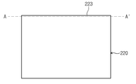
도 22는 도광판 및 발광 다이오드를 나타낸 배면도이다.
도 23은 도 22에 도시된 절단선 Ⅵ-Ⅵ`에 따라 절단한 단면도이다.
도 24는 본 발명의 일 실시예에 따른 반사판을 나타낸 단면도이다.
도 25는 본 발명의 다른 실시예에 따른 반사판을 나타낸 단면도이다.
도 26은 반사판 형상에 따른 입광부 영역의 휘도를 나타낸 그래프이다.
도 27은 본 발명의 다른 실시예에 따른 도광판 및 반사판을 나타낸 단면도이다.
도 28은 도 1에 도시된 절단선 Ⅶ-Ⅶ`에 따라 절단한 단면도이다.
도 29는 본 발명의 다른 실시예에 따른 표시 장치의 단면도이다.
도 30은 본 발명의 다른 실시예에 따른 백라이트 유닛의 평면도이다.
도 31은 도 30에 도시된 절단선 Ⅷ-Ⅷ`에 따라 절단한 단면도이다.1 is an exploded perspective view of a display device according to an embodiment of the present invention.
FIG. 2 is a plan view of the light guide plate and the light emitting diode shown in FIG. 1.
3 is a cross-sectional view taken along the line II ′ of FIG. 2.
4 is a plan view of the protrusion.
FIG. 5 is a cross-sectional view of the protrusion cut along the cutting line II-II ′ and the cutting line III-III ′ shown in FIG. 4.
FIG. 6 are graphs illustrating luminance of each light guide plate according to the position of the protrusion having the same shape as that of the second lenti region in the first lenti region.
7 is graphs illustrating luminance of each light guide plate according to a start point of the first lenti region.
8 is a graph illustrating luminance of each light guide plate according to the width of the first lenti region.
9 is a perspective view of the light guide plate illustrated in FIG. 1.
FIG. 10 is a cross-sectional view taken along the line IV-IV ′ of FIG. 9.
FIG. 11 is a cross-sectional view taken along the cutting line VV ′ of FIG. 9.
12 is a view showing the light receiving efficiency of light incident on the light guide plate when the protrusion is formed on the emission surface.
FIG. 13 is a diagram illustrating light incidence efficiency of light incident on a light guide plate when no protrusion is formed on an emission surface.
14 is a cross-sectional view showing the inclination angle of the inclined surface and the width of the region where the inclined surface is formed.
15 is a plan view of the light guide plate.
FIG. 16 is a graph showing an average luminance when cut along the cutting line BB ′ illustrated in FIG. 15.
17 is a graph showing the light incidence efficiency according to the inclination angle.
18 is a graph illustrating luminance and light incidence efficiency according to the width of a region where an inclined surface is formed.
19A and 19B are diagrams illustrating a light emission path according to the curvature of the protrusion.
20 is a plan view of the light guide plate.
FIG. 21 is a graph illustrating luminance at an imaginary line AA ′ of FIG. 20 according to curvature of the protrusion.
22 is a rear view illustrating the light guide plate and the light emitting diode.
FIG. 23 is a cross-sectional view taken along the line VI-VI ′ of FIG. 22.
24 is a cross-sectional view illustrating a reflector according to an exemplary embodiment of the present invention.
25 is a cross-sectional view illustrating a reflecting plate according to another exemplary embodiment of the present invention.
FIG. 26 is a graph illustrating luminance of a light incident region according to a shape of a reflector.
27 is a cross-sectional view illustrating a light guide plate and a reflecting plate according to another exemplary embodiment of the present invention.
FIG. 28 is a cross-sectional view taken along the cutting line VII-VII ′ of FIG. 1.
29 is a cross-sectional view of a display device according to another exemplary embodiment of the present invention.
30 is a plan view of a backlight unit according to another exemplary embodiment of the present invention.
FIG. 31 is a cross-sectional view taken along the line VII-VII` of FIG. 30.
이상의 본 발명의 목적들, 다른 목적들, 특징들 및 이점들은 첨부된 도면과 관련된 이하의 바람직한 실시예들을 통해서 쉽게 이해될 것이다. 그러나 본 발명은 여기서 설명되는 실시예들에 한정되지 않고 다른 형태로 구체화될 수도 있다. 오히려, 여기서 소개되는 실시예들은 개시된 내용이 철저하고 완전해질 수 있도록 그리고 당업자에게 본 발명의 사상이 충분히 전달될 수 있도록 하기 위해 제공되는 것이다.BRIEF DESCRIPTION OF THE DRAWINGS The above and other objects, features, and advantages of the present invention will become more readily apparent from the following description of preferred embodiments with reference to the accompanying drawings. However, the present invention is not limited to the embodiments described herein but may be embodied in other forms. Rather, the embodiments disclosed herein are provided so that the disclosure can be thorough and complete, and will fully convey the scope of the invention to those skilled in the art.
본 명세서에서, 어떤 구성 요소가 다른 구성 요소 상에 있다고 언급되는 경우에 그것은 다른 구성요소 상에 직접 형성될 수 있거나 또는 그들 사이에 제 3의 구성요소가 개재될 수도 있다는 것을 의미한다. 또한, 도면들에 있어서, 구성요소들의 두께는 기술적 내용의 효과적인 설명을 위해 과장된 것이다. In this specification, when an element is referred to as being on another element, it may be directly formed on another element, or a third element may be interposed therebetween. Further, in the drawings, the thickness of the components is exaggerated for an effective description of the technical content.
본 명세서에서 사용된 용어는 실시예들을 설명하기 위한 것이며 본 발명을 제한하고자 하는 것은 아니다. 본 명세서에서, 단수형은 문구에서 특별히 언급하지 않는 한 복수형도 포함한다. 명세서에서 사용되는 '포함한다(comprises)' 및/또는 '포함하는(comprising)'은 언급된 구성요소는 하나 이상의 다른 구성요소의 존재 또는 추가를 배제하지 않는다.The terminology used herein is for the purpose of describing particular embodiments only and is not intended to be limiting of the invention. In the present specification, the singular form includes plural forms unless otherwise specified in the specification. The terms "comprises" and / or "comprising" used in the specification do not exclude the presence or addition of one or more other elements.
이하, 도면들을 참조하여 본 발명의 실시예들에 대해 상세히 설명하기로 한다.Hereinafter, embodiments of the present invention will be described in detail with reference to the drawings.
도 1은 본 발명의 일 실시예에 따른 표시 장치의 분해 사시도이다.1 is an exploded perspective view of a display device according to an embodiment of the present invention.
도 1을 참조하면, 표시 장치(1000)는 표시 유닛(100), 백라이트 유닛(200), 몰드 프레임(400), 및 바텀 샤시(500)를 포함한다.Referring to FIG. 1, the
상기 표시 장치(1000)를 평면에서 볼 때, 상기 표시 장치(1000)는 직사각형 구조를 가질 수 있다. 상기 표시 장치(1000)의 단축 방향은 제1 방향(D1)으로 정의되고, 상기 표시 장치(1000)의 장축 방향은 상기 제1 방향(D1)과 직교하는 제2 방향(D2)으로 정의된다. 또한, 상기 표시 장치(1000)의 상기 바텀 샤시(500), 백라이트 유닛(200), 몰드 프레임(400) 및 표시 유닛(100)은 상기 제1 및 제2 방향(D1, D2)과 수직한 제3 방향(D3)으로 순차적으로 적층된다.When the
상기 표시 유닛(100)은 영상을 표시하는 표시 패널(106), 상기 표시 패널(106)에 구동신호를 제공하는 구동칩(108) 및 상기 표시 패널(106)에 전기적으로 연결되는 인쇄회로기판(110)을 포함한다.The
상기 표시 패널(106)은 제1 기판(102), 상기 제1 기판(102)과 대향하여 결합하는 제2 기판(104), 및 상기 제1 기판(102)과 상기 제2 기판(104) 사이에 개재되는 액정층(미도시)을 포함한다. 본 발명의 일 예로, 도 1에서는 상기 표시 패널(106)이 액정 표시 패널로 이루어진 경우를 도시하였으나, 상기 표시 패널(106)은 상기 액정 표시 패널에 한정되지 않는다.The
상기 제1 기판(102)에는 다수의 화소가 매트릭스 형태로 구비되고, 다수의 화소 각각은 상기 제1 방향(D1)으로 연장된 게이트 라인(미도시), 상기 제2 방향(D2)으로 연장되어 게이트 라인과 절연되어 교차하는 데이터 라인(미도시) 및 화소 전극(미도시)을 구비한다. 또한, 각 화소에는 박막 트랜지스터(미도시)가 구비되어, 상기 게이트 라인, 데이터 라인 및 화소 전극에 연결된다.A plurality of pixels are provided in a matrix form on the
상기 제2 기판(104)에는 색화소인 RGB(Red Green Blue) 화소(미도시) 및, 화소 전극과 마주보는 공통 전극(미도시)이 형성된다. 상기 색화소와 상기 공통 전극은 상기 제1 기판(102)에 구비될 수도 있다. 상기 액정층은 상기 화소 전극 및 상기 공통 전극 사이에 형성된 전계의 크기에 따라서 배열됨으로써, 상기 백라이트 유닛(200)으로부터 제공되는 광의 투과율을 조절하여 원하는 계조를 표시할 수 있다.In the
평면에서 볼 때, 상기 제1 기판(102)의 적어도 일 측에는 상기 데이터 라인에 데이터 신호를 인가하기 위한 상기 구동칩(108)이 구비될 수 있다. 상기 구동칩(108)은 외부 신호에 응답하여 상기 표시 패널(106)의 상기 데이터 라인으로 인가되기 위한 데이터 신호를 발생한다. 상기 외부 신호는 상기 인쇄회로기판(110)으로부터 공급된 신호이고, 상기 외부 신호에는 영상신호, 각종 제어신호, 구동 전압 등이 포함될 수 있다.In plan view, at least one side of the
상기 제1 기판(102)은 상기 적어도 일 측과 다른 측에 제공되어 상기 게이트 라인에 게이트 신호를 인가하는 게이트 구동회로를 포함한다. 상기 게이트 구동회로는 상기 표시 패널(106)을 형성하는 박막 공정을 통해 상기 다른 일측에 형성될 수 있다. 따라서, 상기 게이트 구동회로는 상기 표시 패널(106) 내에 내장될 수 있다.The
본 발명의 다른 실시예로, 상기 구동칩(108)은 데이터 구동칩과 게이트 구동칩으로 분리된 두 개 이상의 칩으로 구성될 수 있으며, 칩 온 글라스(Chip on Glass) 공정에 의하여 상기 제1 기판(102) 상에 실장될 수 있다.In another embodiment of the present invention, the
상기 인쇄회로기판(110)은 다수의 테이프 캐리어 패키지(Tape Carrier Package; TCP, 109)에 의해 상기 표시 패널(106)과 전기적으로 연결될 수 있다. 상기 구동칩(108)은 상기 TCP들(109) 상에 실장될 수 있다. 상기 TCP들(109)은 상기 바텀 샤시(500)의 측면을 감싸도록 절곡될 수 있다.The printed
상기 TCP들(109)과 연결된 상기 인쇄회로기판(110)은 상기 바텀 샤시(500) 하부에 배치된다. 이 경우, 상기 표시 장치(1000)는 상기 바텀 샤시(500) 하부에 배치되어 상기 인쇄회로기판(110)을 보호하기 위한 쉴드 케이스(미도시)를 더 포함할 수 있다. 도면에 도시하지는 않았지만, 상기 인쇄회로기판(110)은 상기 바텀 샤시(500)의 측벽에 배치될 수 있다.The printed
상기 백라이트 유닛(200)은 광을 발생하는 광원부(210) 및 상기 광원부(210)로부터 상기 광을 입력받아서 상기 표시 유닛(100) 측으로 가이드 하는 도광판(light guide plate, 220)을 포함할 수 있다.The
본 발명의 일 실시예에서, 상기 백라이트 유닛(200)은 측면 조광형 백라이트 유닛(edge type backlight unit)일 수 있다. 즉, 상기 백라이트 유닛(200)의 상기 광원부(210)는 상기 표시 패널(106)의 아래에서 상기 도광판(220)의 적어도 하나의 측면으로 상기 광을 제공하고, 상기 도광판(220)은 상기 광을 상기 표시 유닛(100) 측으로 가이드한다.In one embodiment of the present invention, the
상기 도광판(220)은 상기 표시 장치(1000)의 상기 제1 방향(D1)으로 길게 연장된 제1 측면(221), 상기 제1 측면(221)과 평행한 제2 측면(222), 상기 표시 장치(1000)의 상기 제2 방향(D2)으로 길게 연장된 제3 측면(223), 및 상기 제3 측면(223)과 평행한 제4 측면(224)을 포함한다. 본 발명의 일 실시예에서, 상기 광원부(210)는 상기 도광판(220)의 상기 제3 측면(223)에 인접하여 구비된다. 따라서, 이하에서는 상기 제3 측면(223)을 상기 도광판(220)의 입사면이라고 칭한다.The
상기 광원부(210)는 상기 입사면(223)을 따라 순차적으로 배열된 다수의 발광 다이오드(Light Emitting Diodes; LED)(211)를 포함할 수 있다. 상기 광원부(210)는 상기 다수의 발광 다이오드들(211)이 실장되는 지지 필름(212)을 더 포함할 수 있다. 상기 지지 필름(212) 상에는 상기 다수의 발광 다이오드(211)가 상기 제2 방향(D2)으로 서로 이격되어 배치될 수 있다.The
상기 백라이트 유닛(200)은 상기 도광판(220)과 상기 표시 유닛(100) 사이에 구비되는 다수의 광학 시트들(optical sheets, 230)과 상기 도광판(220)의 하부에 배치되는 반사판(240)을 더 포함한다.The
상기 다수의 광학 시트들(230)은 광의 확산을 위한 확산 시트 및 광을 집광하기 위한 적어도 1매의 집광 시트로 이루어져 출사면으로 출사되는 광의 휘도 및 시야각을 향상시킨다. 도면에 도시하지는 않았지만, 상기 다수의 광학 시트들(230)은 시트들의 최상측에 구비된 보호시트를 더 포함할 수 있다. 상기 반사판(240)은 상기 도광판(220)의 하측에 구비되어 상기 도광판(220)으로부터 누설된 광을 반사하여 다시 상기 도광판(220) 측으로 재입사시키는 역할을 수행한다.The plurality of
상기 바텀 샤시(500)는 상기 백라이트 유닛(200)이 안착되는 바닥부(502), 상기 바닥부(502)로부터 수직 방향(즉, 상기 제3 방향(D3))으로 연장된 측벽(504), 및 상기 측벽(504)으로부터 상기 바닥부(502)와 평행하게 연장되어 상기 광원부(210)을 커버하는 커버부(506)를 포함할 수 있다.The
상기 몰드 프레임(400)은 상기 표시 유닛(100) 및 백라이트 유닛(200) 사이에 개재되어, 상기 표시 패널(106)을 지지한다. 상기 몰드 프레임(400)은 상기 표시 패널(106)을 지지하기 위한 지지부(410) 및 상기 지지부(410)로부터 상기 제3 방향(D3)으로 연장된 측벽(420)을 포함한다. 상기 몰드 프레임(400)는 상기 광원부(210)에 인접하는 상기 지지부(410) 및 측벽(420)을 부분적으로 제거하여 상기 바텀 샤시(500)의 커버부(506)를 노출시킬 수 있다. 따라서, 상기 광원부(210)에 인접한 영역(이하, 입광부 영역)에서 상기 표시 패널(106)은 상기 커버부(506) 상에 안착될 수 있다.The
상기 표시 패널(106)과 상기 커버부(506) 사이에는 양면 테이프(미도시)가 개재될 수 있다. 따라서, 상기 표시 패널(106)은 상기 양면 테이프에서 의해서 상기 커버부(506)에 고정될 수 있다. Double-sided tape (not shown) may be interposed between the
또한, 상기 표시 패널(106)의 가장 자리에는 상기 표시 패널(106)을 상기 몰드 프레임(400)에 고정하기 위한 고정 테이프(미도시)가 더 부착될 수 있다.A fixing tape (not shown) for fixing the
도면에 도시하지는 않았지만, 다른 실시예로 상기 고정 테이프를 대신하여 상기 표시 장치(1000)는 상기 바텀 샤시(500)와 대향하여 결합하고, 상기 표시 패널(106)의 가장 자리를 커버하는 탑 샤시를 더 포함할 수 있다.Although not shown in the drawing, in another embodiment, the
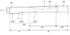
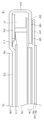
도 2는 도 1에 도시된 도광판 및 발광 다이오드의 평면도이고, 도 3은 도 2에 도시된 절단선 I-I`에 따라 절단한 단면도이다.FIG. 2 is a plan view of the light guide plate and the light emitting diode shown in FIG. 1, and FIG. 3 is a cross-sectional view taken along the line II ′ of FIG. 2.
도 2 및 도 3을 참조하면, 상기 도광판(220)은 상기 표시 장치(1000)의 상기 제1 방향(D1)으로 길게 연장된 제1 측면(221), 상기 제1 측면(221)과 평행한 제2 측면(222), 상기 표시 장치(1000)의 상기 제2 방향(D2)으로 길게 연장된 제3 측면(223), 및 상기 제3 측면(223)과 평행한 제4 측면(224)을 포함한다.2 and 3, the
본 발명의 일 예로, 상기 다수의 발광 다이오드(211)는 상기 제3 측면(즉, 입사면)(223)에 인접하여 배열된다. 상기 발광 다이오드들(211)은 광을 발생하고, 상기 도광판(220)은 상기 제3 측면(223)을 통해 상기 광을 수신한다. 즉, 상기 제3 측면(223)은 상기 도광판(220)의 입사면으로 정의되고, 상기 제3 측면(223)과 평행한 상기 제4 측면(224)은 상기 입사면과 마주하는 대광면으로 정의될 수 있다. For example, the plurality of
상기 도광판(220)은 상기 입사면(223)을 통해 입사된 광을 출사하는 출사면(225) 및 상기 출사면(225)과 마주하고, 상기 입사된 광을 반사하는 반사면(226)을 더 포함한다.The
상기 반사면(226)은 상기 출사면(225)과 평행한 제1 플랫면(226a), 상기 입사면(223)에 인접하고 상기 출사면(225) 측으로 기울어진 경사면(226b) 및 상기 경사면(226b)과 상기 입사면(223)을 연결하는 제2 플랫면(226c)으로 이루어진다. 상기 경사면(226b)은 상기 입사면(223) 측으로 갈수록 상기 출사면(225)으로부터 멀어지는 방향으로 기울어진다. 상기 제2 플랫면(226c)은 상기 경사면(226b)과 상기 입사면(223) 사이에서 상기 출사면(225)과 평행하게 구비된다.The
상기 경사면(226b)이 상기 제2 플랫면(226c)에 대해서 기울어진 각도(이하, 경사 각도)(α)는 2° 내지 5°일 수 있다. 상기 경사면(226b)의 경사 각도(α)가 증가할수록 상기 광원부(210)에 인접하는 상기 도광판 영역(이하, 입광부 영역)에서의 빛샘이 증가할 수 있다. 따라서, 빛샘 증가를 엑제하기 위하여 상기 경사면(226b)의 경사 각도는 2° 내지 5°로 설정될 수 있다.An angle (hereinafter, inclined angle) α in which the
상기 도광판(220)은 상기 출사면(225) 상에 렌티큘러 형상으로 제공된 돌출부(227)를 더 포함한다.The
본 발명의 일 예로, 상기 출사면(225)은 상기 입사면(223)으로부터 순차적으로 인접하는 제1 및 제2 영역(A1, A2)으로 구분된다. 이 경우, 상기 돌출부(227)는 상기 제1 영역(A1)에는 형성되지 않고, 상기 제2 영역(A2)에만 제공된다. 본 발명의 일 예로, 상기 제2 영역(A2)은 제1 렌티 영역(RA1) 및 제2 렌티 영역(RA2)을 포함한다.For example, the
상기 제1 렌티 영역(RA1)에서 상기 돌출부(227)는 상기 제3 측면(223)의 길이 방향(D2)과 수직한 방향(D1)으로 연장된 반원뿔 형상을 갖고, 제2 렌티 영역(RA2)에서 상기 돌출부(227)는 상기 입사면(223)의 길이 방향(D2)과 수직한 방향(D1)으로 연장된 반원기둥 형상을 갖는다. 구체적으로, 상기 제1 렌티 영역(RA1)에서 상기 돌출부(227)의 높이는 상기 입사면(223)으로부터 멀어질수록 증가하고, 상기 돌출부(227)의 직경도 상기 입사면(223)으로부터 멀어질수록 증가한다.The
도 4는 돌출부의 평면도이고, 도 5는 도 4에 도시된 절단선 Ⅱ-Ⅱ` 및 절단선 Ⅲ-Ⅲ`에 따라 절단한 돌출부의 단면도이다.4 is a plan view of the protrusion, and FIG. 5 is a cross-sectional view of the protrusion cut along the cutting line II-II ′ and the cutting line III-III ′ of FIG. 4.
도 4 및 도 5를 참조하면, 상기 돌출부(227)는 상기 입사면(223)의 길이 방향(D2)으로 절단했을 때, 반원 형상을 갖는다. 상기 돌출부(227)의 높이를 'h'라 하고, 직경을 'd'라고 정의할 때, 상기 제1 렌티 영역(RA1)에서 상기 돌출부(227)의 높이(h) 및 직경(d)은 선형적으로 증가한다. 상기 돌출부(227)의 높이(h) 및 직경(d)이 증가되는 비율은 서로 동일하여, 상기 제1 렌티 영역(RA1)에서 상기 돌출부(227)의 곡률 반경은 일정하다.4 and 5, the
한편, 상기 제2 렌티 영역(RA2)에서 상기 돌출부(227)는 일정한 높이(h) 및 일정한 직경(d)을 갖는다. 본 발명의 일 예로, 상기 돌출부(227)는 상기 제1 및 제2 렌티 영역(RA1, RA2)에서 동일한 곡률 반경을 갖는다. Meanwhile, in the second lenti region RA2, the
그러나, 본 발명의 다른 실시예로 상기 돌출부(227)는 상기 제2 렌티 영역(RA2)에서도 반원뿔 형상을 가질 수 있다. 즉, 상기 제2 렌티 영역(RA2)에서도 상기 돌출부(227)의 높이(h) 및 직경(d)은 상기 입사면(223)으로부터 멀어질수록 증가할 수 있다.However, in another embodiment of the present invention, the
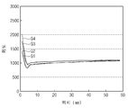
도 6은 제1 렌티 영역에 제2 렌티 영역과 동일한 형상의 돌출부가 구비된 경우에 대한 도광판의 위치별 휘도를 나타낸 그래프들이다. 도 6에서, x축은 도광판의 위치를 나타내고, y축은 휘도를 나타낸다. 또한, 도 6에서, 제1 그래프(G1)는 돌출부(227)의 높이(h)가 7㎛이고, 직경(d)이 100㎛인 경우의 휘도를 나타내고, 제2 그래프(G2)는 돌출부(227)의 높이(h)가 8㎛이고, 직경(d)이 100㎛인 경우의 휘도를 나타내며, 제3 그래프(G3)는 돌출부(227)의 높이(h)가 10㎛이고, 직경(d)이 100㎛인 경우의 휘도를 나타내고, 제4 그래프(G4)는 돌출부(227)의 높이(h)가 10㎛이고, 직경(d)이 50㎛인 경우의 휘도를 나타낸다.FIG. 6 are graphs illustrating luminance of each light guide plate according to the position of the protrusion having the same shape as that of the second lenti region in the first lenti region. In FIG. 6, the x axis represents the position of the light guide plate and the y axis represents the luminance. 6, the first graph G1 represents luminance when the height h of the
도 6을 참조하면, 상기 제1 렌티 영역(RA1)에도 상기 제2 렌티 영역(RA2)과 동일한 형상의 돌출부(227)가 제공되는 경우, 상기 도광판(220)의 입광부 영역에서 휘도가 급격하게 증가하여 빛샘 현상이 나타나는 것을 볼 수 있다.Referring to FIG. 6, when the
특히, 동일 직경(즉, 100㎛)(d)에서 상기 돌출부(227)의 높이(h)가 증가할수록 상기 입광부 영역의 휘도가 높게 나타났다. 또한, 동일 높이(즉, 10㎛)에서 상기 돌출부(227)의 직경(d)이 작을수록 상기 입광부 영역의 휘도가 높게 나타났다. 결과적으로, 상기 돌출부(227)의 곡률이 클수록 빛샘 현상이 두드러지게 나타난다는 것을 알 수 있다.In particular, as the height h of the
도 7은 제1 렌티 영역의 시작 지점에 따른 도광판의 위치별 휘도를 나타낸 그래프들이다. 도 7에서, x축은 도광판(220)의 위치를 나타내고, y축은 휘도를 나타낸다. 또한, 도 7에서, 제5 그래프(G5)는 상기 제1 렌티 영역(RA1)이 상기 도광판(220)의 0mm 내지 50mm의 위치 범위로 정의된 제1 경우의 휘도를 나타내고, 제6 그래프(G6)는 상기 제1 렌티 영역(RA1)이 상기 도광판(220)의 3.5mm 내지 50mm의 위치 범위로 정의된 제2 경우의 휘도를 나타내며, 제7 그래프(G7)는 상기 제1 렌티 영역(RA1)이 상기 도광판(220)의 2.5mm 내지 50mm의 위치 범위로 정의된 제3 경우의 휘도를 나타낸다.7 is graphs illustrating luminance of each light guide plate according to a start point of the first lenti region. In FIG. 7, the x axis represents the position of the
도 7을 참조하면, 상기 제1 경우에 상기 제1 렌티 영역(RA1)은 상기 출사면(225)이 상기 도광판(220)의 상기 입사면(223)과 접한 지점부터 시작된다. 그러나, 상기 제2 및 제3 경우에 상기 제1 렌티 영역(RA1)은 상기 입사면(223)으로부터 각각 3.5 및 2.5mm 만큼 이격된 위치에서 시작된다.Referring to FIG. 7, in the first case, the first lenti area RA1 starts from a point where the
상기 제5 내지 제7 그래프(G5~G7)에 나타난 바와 같이, 상기 제1 경우는 제2 및 제3 경우보다 상기 입광부 영역에서의 휘도가 높게 나타났다. 즉, 상기 제1 렌티 영역(RA1)이 상기 입사면(223)과 접한 지점부터 시작되면, 빛샘 현상이 나타났다.As shown in the fifth to seventh graphs G5 to G7, the luminance in the light incident region is higher in the first case than in the second and third cases. That is, when the first lenti area RA1 starts from the point of contact with the
따라서, 상기 제1 렌티 영역(RA1)과 상기 입사면(223) 사이에 상기 돌출부(227)가 형성되지 않는 상기 제1 영역(A1, 도 2에 도시됨)을 제공하여 빛샘 현상을 억제시킬 수 있다.Accordingly, light leakage may be suppressed by providing the first region A1 (not shown in FIG. 2) in which the
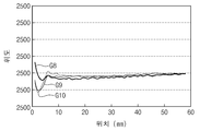
도 8은 제1 렌티 영역의 폭에 따른 도광판의 위치별 휘도를 나타낸 그래프들이다. 도 8에서, x축은 도광판(220)의 위치를 나타내고, y축은 휘도를 나타낸다. 또한, 도 8에서, 제8 그래프(G8)는 상기 제1 렌티 영역(RA1)이 상기 도광판(220)의 2.5mm 내지 10mm의 위치 범위에 제공된 제4 경우의 휘도를 나타내고, 제9 그래프(G9)는 상기 제1 렌티 영역(RA1)이 상기 도광판(220)의 3.5mm 내지 50mm의 위치 범위에 제공된 제5 경우의 휘도를 나타내며, 제10 그래프(G10)는 상기 제1 렌티 영역(RA1)이 상기 도광판(220)의 5mm 내지 25mm의 위치 범위에 제공된 제6 경우의 휘도를 나타낸다.8 is a graph illustrating luminance of each light guide plate according to the width of the first lenti region. In FIG. 8, the x axis represents the position of the
도 8을 참조하면, 상기 제4 경우에 상기 제1 렌티 영역(RA1)은 7.5mm의 폭을 갖고, 상기 제2 경우에 상기 제1 렌티 영역(RA1)은 46.5mm의 폭을 가지며, 제3 경우에 상기 제1 렌티 영역(RA1)은 20mm의 폭을 갖는다. 여기서, 상기 제1 렌티 영역(RA1)의 폭은 상기 입사면(223)의 길이 방향에 수직한 방향으로의 폭을 나타낸다.Referring to FIG. 8, in the fourth case, the first lenti area RA1 has a width of 7.5 mm, and in the second case, the first lenti area RA1 has a width of 46.5 mm and a third width. In this case, the first lenti region RA1 has a width of 20 mm. Here, the width of the first lenti area RA1 represents a width in a direction perpendicular to the longitudinal direction of the
상기 제1 렌티 영역(RA1)의 폭이 작을수록 상기 제1 렌티 영역(RA1)에 형성되는 상기 돌출부(227)의 경사도는 증가하게 된다. 즉, 제4 경우와 같이 상기 제1 렌티 영역(RA1)의 폭이 7.5mm로 좁은 경우, 7.5mm의 폭 내에서 상기 돌출부(227)가 원하는 높이에 도달하기 위해서는 상기 돌출부(227)의 경사도가 급해진다. 그러나, 상기 제5 경우와 같이 상기 제1 렌티 영역(RA1)의 폭이 46.5mm로 넓은 경우, 상기 돌출부(227)의 경사도는 완만해진다.As the width of the first lenient region RA1 is smaller, the inclination of the
상기 제8 내지 제10 그래프(G8~G10)에 나타난 바와 같이, 상기 제1 렌티 영역(RA1)의 폭이 7.5mm로 좁은 상기 제4 경우에 상기 입광부 영역에서 휘도가 증가하여 빛샘 현상이 나타났다.As shown in the eighth to tenth graphs G8 to G10, in the fourth case in which the width of the first lentid area RA1 is narrow to 7.5 mm, the luminance is increased in the light incident area, resulting in a light leakage phenomenon. .
다시 도 3을 참조하면, 상기 제1 렌티 영역(RA1)의 폭을 'a'로 정의하고, 상기 제1 렌티 영역(RA1)에서 상기 돌출부(227)의 최대 높이를 'b'라고 정의할 때, 상기 a와 b는 아래 수학식을 만족한다. 여기서, 상기 제1 렌티 영역(RA1)의 폭(a)은 상기 입사면(223)의 길이 방향(D2)과 수직한 방향(D1)으로의 폭을 나타낸다.Referring back to FIG. 3, when the width of the first lenti area RA1 is defined as 'a' and the maximum height of the
<수학식>≪ Equation &

위에서 검토한 바와 같이 빛샘 현상을 억제하기 위하여 상기 돌출부(227)는 경사도가 완만하게 형성되어야 한다. 그러기 위해, 본 발명의 일 예로 상기 θ가 0.03°보다 작은 값을 갖도록 상기 돌출부(227)를 형성할 수 있다.As discussed above, in order to suppress light leakage, the
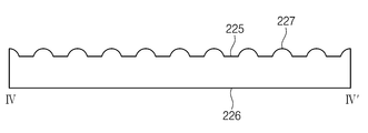
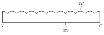
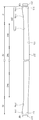
도 9는 도 1에 도시된 도광판의 사시도이고, 도 10은 도 9에 도시된 절단선 Ⅳ-Ⅳ`에 따라 절단한 단면도이며, 도 11은 도 9에 도시된 절단선 Ⅴ-Ⅴ`에 따라 절단한 단면도이다.FIG. 9 is a perspective view of the light guide plate illustrated in FIG. 1, and FIG. 10 is a cross-sectional view taken along the line IV-IV ′ of FIG. 9, and FIG. 11 is a line along the line V-V ′ of FIG. 9. It is a cut section.
도 9 및 도 10을 참조하면, 상기 도광판(220)은 상기 출사면(225) 상에 렌티큘러 형상으로 돌출부(227)가 제공된다. 여기서, 상기 렌티 큘러 형상은 반원 렌즈 형상을 지칭한다. 그러나, 상기 렌티 큘러 형상은 반원 렌즈 형상에 한정되지는 않고, 반타원 형상 등을 포함할 수 있다.9 and 10, the
상기 출사면(225)은 상기 입사면(223)으로부터 순차적으로 인접하는 제1 및 제2 영역(A1, A2)으로 구분된다. 이 경우, 상기 돌출부(227)는 상기 제1 영역(A1)에는 형성되지 않고, 상기 제2 영역(A2)에만 제공된다. 본 발명의 일 예로, 상기 제2 영역(A2)은 제1 렌티 영역(RA1) 및 제2 렌티 영역(RA2)을 포함한다.The
상기 제1 렌티 영역(RA1)에서 상기 돌출부(227)는 상기 입사면(223)의 길이 방향(D2)과 수직한 방향(D1)으로 연장된 반원뿔 형상을 갖고, 제2 렌티 영역(RA2)에서 상기 돌출부(227)는 상기 입사면(223)의 길이 방향(D2)과 수직한 방향(D1)으로 연장된 반원 기둥 형상을 갖는다. 구체적으로, 상기 제1 렌티 영역(RA1)에서 상기 돌출부(227)의 높이는 상기 입사면(223)으로부터 멀어질수록 증가하고, 상기 돌출부(227)의 직경도 상기 입사면(223)으로부터 멀어질수록 증가한다.The
도 10에 도시된 바와 같이, 상기 제1 렌티 영역(RA1)에서 상기 도광판(220)을 상기 입사면(223)의 길이 방향(D2)으로 절단했을 때, 상기 돌출부(227)의 단면은 반원 형상을 갖는다.As shown in FIG. 10, when the
도 11에 도시된 바와 같이, 상기 제2 렌티 영역(RA2)에서 상기 도광판(220)을 상기 입사면(223)의 길이 방향(D2)으로 절단했을 때, 상기 돌출부(227)의 단면은 반원 형상을 갖는다. 상기 제2 렌티 영역(RA2)에서의 상기 돌출부(227)의 높이(h)와 직경(d)은 상기 제1 렌티 영역(RA1)에서의 상기 돌출부(227)의 높이(h)와 직경(d)보다 크다.As shown in FIG. 11, when the
특히, 상기 제2 렌티 영역(RA2)에서 상기 돌출부(227)는 상기 입사면(223)의 길이 방향(D2)으로 연속하여 배열된다. 그러나, 상기 제1 렌티 영역(RA1)에서 상기 돌출부(227)는 상기 제2 렌티 영역(RA2)에서의 상기 돌출부(227)보다 작은 직경을 가지므로, 상기 제1 렌티 영역(RA1)에서 상기 돌출부(227) 주변에는 플랫면(즉, 출사면)(225)이 존재할 수 있다.In particular, the
도 12는 출사면 상에 돌출부가 형성되었을 때 도광판으로 입사된 광의 입광 효율을 나타낸 도면이고, 도 13은 출사면 상에 돌출부가 형성되지 않았을 때 도광판으로 입사된 광의 입광 효율을 나타낸 도면이다. 여기서, 입광 효율은 상기 입사면(223)을 통해 입사된 광 대비 상기 대광면(224)을 통해 출사되는 광의 비율을 나타낸다.FIG. 12 is a view illustrating light incidence efficiency of light incident on the light guide plate when the protrusion is formed on the emission surface, and FIG. 13 is a view illustrating light incidence efficiency of light incident on the light guide plate when the protrusion is not formed on the emission surface. Here, the light incidence efficiency indicates a ratio of light emitted through the
도 12를 참조하면, 도광판(220)의 입사면(223) 측에는 다수의 발광 다이오드(211)가 상기 입사면(223)의 길이 방향을 따라서 배열된다. 상기 출사면(225) 상에 상기 돌출부(227)가 형성되었을 때 상기 발광 다이오들(211) 중 일부의 발광 다이오드(예를 들어, 중앙에 위치한 3개의 발광 다이오드)를 턴-온시켜 광 출사 경로를 촬영하였다.Referring to FIG. 12, a plurality of
도 13을 참조하면, 도 12에 도시된 바와 같이 도광판(220)의 입사면(223) 측에 배열된 다수의 발광 다이오드(211) 중 중앙에 위치한 3개의 발광 다이오드를 턴-온시켜 광 출사 경로를 촬영하였다. 다만, 도 13에 도시된 도광판(220)의 출사면(225) 상에는 상기 돌출부(227)가 형성되지 않았다.Referring to FIG. 13, as shown in FIG. 12, three light emitting diodes positioned at the center of the plurality of
도 12 및 도 13을 참조하면, 상기 돌출부(227)가 형성된 경우 상기 도광판(220)의 제1 및 제2 측면(221, 222)으로 진행하는 광의 양이 상기 돌출부(227)가 형성되지 않은 경우보다 적은 것을 볼 수 있다. 한편, 상기 입사면(223)과 마주하는 대광면(즉, 제4 측면)(224) 측으로 진행하는 광의 양은 상기 돌출부(227)가 형성된 구조에서 더 증가하였다. 즉, 상기 돌출부(227)가 형성된 경우 상기 도광판(220)의 입광 효율이 증가하였다.12 and 13, when the
또한, 상기 돌출부(227)가 상기 출사면(225) 상에 형성되면, 상기 제1 및 제2 측면(221, 222)으로 광이 누설되는 양을 감소시킬 수 있고, 상기 도광판(220)의 출사면(225)을 통해 출사되는 광의 양을 증가시킬 수 있다.In addition, when the
<표 1>에 나타난 바와 같이, 상기 입사면(223)을 통해 입사되는 광의 양을 100%라고 할 때, 상기 돌출부(227)가 있는 경우 제1 및 제2 측면(221, 222)을 통해 누설되는 광의 양은 3.1%에 불과하지만, 상기 돌출부(227)가 없는 경우 13.7%로 대략 4배 정도 크다. 한편, 정면(즉, 출사면)(225)을 통해 출사되는 광량은 상기 돌출부(227)가 있는 경우 87.24%로, 상기 돌출부(227)가 없는 경우에 비하여 대략 10% 정도 증가하였다.As shown in Table 1, when the amount of light incident through the
즉, 상기 출사면(225) 상에 상기 돌출부(227)를 형성하면, 상기 도광판(220)의 정면 휘도가 증가하여 상기 백라이트 유닛(200)의 광 효율이 향상될 수 있다.That is, when the
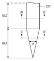
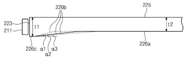
도 14는 경사면의 경사 각도 및 경사면이 형성된 영역의 폭을 나타낸 단면도이다.14 is a cross-sectional view showing the inclination angle of the inclined surface and the width of the region where the inclined surface is formed.
도 14를 참조하면, 상기 도광판(220)의 상기 반사면(226)은 상기 출사면(225)과 평행한 제1 플랫면(226a), 상기 입사면(223)에 인접하고 상기 출사면(225) 측으로 기울어진 경사면(226b) 및 상기 경사면(226b)와 상기 입사면(223)을 연결하는 제2 플랫면(226c)으로 이루어진다. 상기 경사면(226b)은 상기 입사면(223) 측으로 갈수록 상기 출사면(225)으로부터 멀어지는 방향으로 기울어진다.Referring to FIG. 14, the
상기 도광판(220)은 상기 제2 플랫면(226c) 위치에서 제1 두께(t1)를 갖는다. 즉, 상기 제1 두께(t1)는 상기 제2 플랫면(226c)과 상기 출사면(225) 사이의 이격 거리(t1)와 같다. 상기 경사면(226b) 위치에서 상기 도광판(220)의 두께는 점차적으로 감소하고, 상기 제1 플랫면(226a) 위치에서 상기 도광판(220)의 두께는 일정하게 유지된다. 즉, 상기 제1 플랫면(226a) 위치에서 상기 제1 플랫면(226a)과 출사면(225) 사이의 이격 거리와 동일한 제2 두께(t2)를 갖는다. 본 발명의 일 예로, 상기 제1 두께(t1)는 0.54mm이고, 상기 제2 두께(t2)는 0.4mm일 수 있다.The
상기 경사면(226b)은 상기 제1 플랫면(226a)과 상기 제2 플랫면(226c)을 연결한다. 상기 경사면(226b)을 빗변으로 하는 삼각형을 정의할 때, 상기 삼각형의 밑변이 상기 경사면(226b)이 형성된 영역의 폭으로 정의될 수 있다. 본 발명의 일 예로, 상기 경사면(226b)이 형성된 영역의 폭은 1.3mm 내지 2.5mm의 범위의 값을 가질 수 있다. 상기 삼각형의 높이는 상기 제1 두께(t1)와 상기 제2 두께(t2)의 차이값에 해당하는 크기를 가질 수 있다. 또한, 본 발명에서 상기 빗변의 길이가 변하더라도, 상기 삼각형의 높이는 일정하다.The
이 경우, 상기 경사면(226b)의 경사 각도가 제1 각도(α1), 제2 각도(α2) 및 제3 각도(α3) 순으로 감소할수록 상기 경사면(226b)의 경사도는 완만해진다. 여기서, 상기 경사 각도는 상기 삼각형의 밑변과 상기 빗변 사이의 각도로 정의된다. 상기 삼각형의 높이는 일정하므로, 상기 경사 각도가 증가할수록 상기 삼각형의 밑변의 길이가 감소한다. 즉, 상기 경사면(226b)이 형성된 영역의 폭은 상기 경사 각도가 증가할수록 감소한다.In this case, as the inclination angle of the
상기 경사면(226b)이 형성된 영역의 폭이 1.0mm 이하로 감소할 경우 상기 입광부 영역에서의 빛샘이 증가한다. 이것은 상기 경사면(226b)의 경사도가 급하면 빛샘이 증가한다는 것을 의미하므로, 상기 경사면(226b)의 경사 각도는 2° 내지 5°일 수 있다.When the width of the area where the
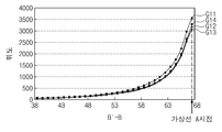
도 15는 도광판의 평면도이고, 도 16은 도 15에 도시된 절단선 B-B`에 따라 절단했을 때 평균 휘도를 나타낸 그래프이다. 도 17은 경사 각도에 따라 입광 효율을 나타낸 그래프이고, 도 18은 경사부의 폭에 따른 휘도 및 입광 효율을 나타낸 그래프이다.FIG. 15 is a plan view of the light guide plate, and FIG. 16 is a graph illustrating average luminance when the light is cut along the cutting line B-B ′ of FIG. 15. 17 is a graph showing light incidence efficiency according to an inclination angle, and FIG. 18 is a graph showing brightness and light incidence efficiency according to a width of an inclined portion.
도 15 및 도 16을 참조하면, 절단선 B-B`는 상기 도광판(220)을 상기 입사면(223)으로부터 상기 대광면(224) 방향으로 절단한 것이며, 가상선 A를 기준으로 상기 도광판(220)의 출사면(225)은 유효광 출사 영역(AE)과 비유효광 출사 영역(NAE)으로 구분된다. 즉, 상기 입사면(223)으로부터 상기 가상선 A까지 영역은 상기 비유효광 출사 영역(NAE)으로 정의되고, 상기 가상선 A로부터 상기 대광면(224)까지의 영역은 상기 유효광 출사 영역(AE)으로 정의된다.15 and 16, the cutting line BB ′ is a portion in which the
도 16은 상기 유효광 출사 영역에서 상기 B' 지점부터 가상선 A까지의 평균 휘도를 나타낸 그래프이다. 도 16에서, 제11 그래프(G11)는 경사면(226b)이 형성된 영역의 폭가 1.0mm인 경우의 평균 휘도를 나타내고, 제12 그래프(G12)는 경사면(226b)이 형성된 영역의 폭이 1.3mm인 경우의 평균 휘도를 나타내며, 제13 그래프(G13)는 경사면(226b)이 형성된 영역의 폭이 1. 6mm인 경우의 평균 휘도를 나타내고, 제14 그래프(G14)는 경사면(226b)이 형성된 영역의 폭이 2.5mm인 경우의 평균 휘도를 나타낸다.16 is a graph showing an average luminance from the point B 'to the virtual line A in the effective light emission area. In FIG. 16, the eleventh graph G11 represents the average luminance when the width of the region on which the
도 16에 도시된 바와 같이, 상기 경사면(226b)이 형성된 영역 폭이 1.0mm인 경우 상기 가상선 A에서의 평균 휘도가 가장 높게 나타났다. 특히, 상기 경사면(226b)이 형성된 영역의 폭이 1.3mm 내지 2.5mm인 경우 상기 가상선 A에서의 평균 휘도는 큰 차이가 없었으나, 상기 경사면(226b)이 형성된 영역의 폭이 1.0인 경우 상기 가상선 A에서의 평균 휘도가 대략 200lux 내지 500lux 정도 높게 나타났다.As shown in FIG. 16, when the area width on which the
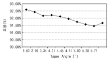
도 17에 도시된 바와 같이, 상기 경사면(226b)의 경사 각도에 따른 입광 효율은 대략 1%의 편차를 보였다. 또한, 도 18에 도시된 바와 같이, 상기 경사면(226b)이 형성된 영역의 폭에 따른 입광 효율도 대략 1% 이내의 편차를 보였다. 따라서, 상기 경사면(226b)의 경사 각도 및 상기 경사면(226b)이 형성된 영역의 폭은 입광 효율 측면에서는 큰 차이가 없다.As shown in FIG. 17, the light incidence efficiency according to the inclination angle of the
그러나, 도 16 및 도 18에 도시된 바와 같이, 상기 경사면(226b)이 형성된 영역의 폭이 1.0mm 이하로 감소하는 경우 평균 휘도가 급격하게 증가하는 것으로 나타났다. 도 18에서, 제15 그래프(G15)는 상기 경사면(226b)이 형성된 영역의 폭에 따른 입광 효율을 나타내고, 제16 그래프(G16)는 경사면(226b)이 형성된 영역의 폭에 따른 휘도를 나타낸다. However, as shown in FIGS. 16 and 18, when the width of the region in which the
본 발명에서는 평균 휘도가 급격하게 증가하여 발생하는 빛샘 현상을 억제하기 위하여, 상기 경사면(226b)의 경사도가 완만해지도록 상기 경사면(226b)이 형성되는 폭을 1.3mm 이상으로 형성하고, 경사 각도(α)를 2° 내지 5°로 형성할 수 있다.In the present invention, in order to suppress the light leakage caused by the rapid increase in the average brightness, the width of the
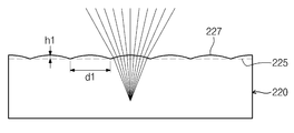
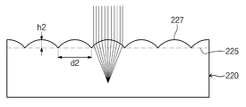
도 19a 및 도 19b는 돌출부의 곡률에 따른 광 출사 경로를 나타낸 도면들이다. 단, 도 19a의 돌출부(227)는 8㎛의 제1 높이(h1)와 160㎛의 제1 직경(d1)을 갖고, 도 19b의 돌출부(227)는 20㎛의 제2 높이(h2)와 72.5㎛의 제2 직경(d2)을 갖는다.19A and 19B are diagrams illustrating a light emission path according to the curvature of the protrusion. However, the
도 19a 및 도 19b를 참조하면, 상기 돌출부(227)의 곡률이 증가할수록 상기 도광판(220)으로부터 출사되는 광이 제1 및 제2 측면(221, 222) 측으로 확산되지 않고 직진성을 갖는 것으로 나타났다. 따라서, 상기 돌출부(227)의 곡률이 증가할수록 상기 도광판(220)의 광 효율이 증가할 수 있다.Referring to FIGS. 19A and 19B, as the curvature of the
그러나, 상기 돌출부(227)의 곡률이 증가하면, 상기 도광판(220)의 입광부 영역에서의 빛샘 현상이 증가할 수 있다.However, when the curvature of the
도 20은 도광판의 평면도이고, 도 21은 돌출부의 곡률에 따른 도 20의 가상선 A-A' 위치에서의 휘도를 나타낸 그래프이다. 도 21에서, 제17 그래프(G17)는 돌출부(227)가 10㎛의 높이와 50㎛의 직경을 갖는 제7 경우의 휘도를 나타내고, 제18 그래프(G18)는 돌출부(227)가 10㎛의 높이와 100㎛의 직경을 갖는 제8 경우의 휘도를 나타내며, 제19 그래프(G19)는 돌출부(227)가 5㎛의 높이와 100㎛의 직경을 갖는 제9 경우의 휘도를 나타낸다.FIG. 20 is a plan view of the light guide plate, and FIG. 21 is a graph showing luminance at an imaginary line A-A 'of FIG. 20 according to curvature of the protrusion. In FIG. 21, the seventeenth graph G17 shows the luminance in the seventh case where the
도 20 및 도 21을 참조하면, 상기 돌출부(227)의 높이가 10㎛로 동일한 제7 및 제9의 경우를 비교했을 때, 직경이 보다 큰 제9 경우가 상기 제7 경우보다 상기 가상선 A-A' 위치에서 낮은 휘도로 나타났다. 또한, 상기 돌출부(227)의 직경이 100㎛로 동일한 제8 및 제9의 경우를 비교했을 때, 높이가 낮은 제9 경우가 상기 제8 경우보다 상기 가상선 A-A'의 위치에서 낮은 휘도로 나타났다.20 and 21, when comparing the seventh and ninth cases where the height of the
이로부터 알 수 있듯이, 상기 돌출부(227)의 곡률이 클수록 입광부 영역에서의 휘도가 증가한다. 따라서, 상기 돌출부(227)의 곡률은 빛샘 현상이 나타나지 않도록 적절히 설정하는 것이 중요하다. 본 발명의 일 예로, 상기 입광부 영역에서의 휘도가 1500lux 이하로 감소하도록 상기 돌출부(227)는 8㎛ 이하의 높이와 100㎛이상의 직경을 갖도록 설계될 수 있다.As can be seen from this, as the curvature of the
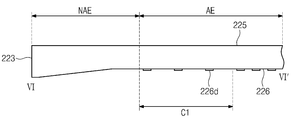
도 22는 도광판 및 발광 다이오드를 나타낸 배면도이고, 도 23은 도 22에 도시된 절단선 Ⅵ-Ⅵ`에 따라 절단한 단면도이다.FIG. 22 is a rear view illustrating the light guide plate and the light emitting diode, and FIG. 23 is a cross-sectional view taken along the cutting line VI-VI ′ of FIG. 22.
도 22 및 도 23을 참조하면, 상기 도광판(220)의 반사면(226)에는 반사 패턴(226d)이 형성된다. 상기 반사 패턴(226d)은 상기 도광판(220)의 입사면(223)을 통해 수신된 광을 반사하여 상기 출사면(225) 측으로 제공하는 역할을 수행한다.22 and 23, a
그러나, 상기 출사면(225) 상에 렌티큘러 형상의 돌출부(227)가 형성되고, 상기 반사면(226)에 경사면(226d)이 형성되는 경우, 상기 도광판(220)의 유효광 출사영역(AE) 중 서로 인접하는 두 개의 발광 다이오드(211) 사이에 대응하는 영역의 휘도가 상대적으로 밝게 나타나는 핫 스팟(hot spot) 현상이 나타날 수 있다. 따라서, 본 발명의 일 예로, 상기 핫 스팟 현상이 시인되지 않도록 상기 반사 패턴(226d)의 밀도를 조절할 수 있다.However, when the
본 발명의 일 예로, 상기 반사 패턴(226d)은 상기 도광판(220)의 상기 유효광 출사영역(AE)에 대응하여 상기 반사면(226)에 형성된다. As an example, the
상기 유효광 출사 영역(AE) 중 상기 두 개의 발광 다이오드(211) 사이에서 상대적으로 휘도가 높게 나타나는 명부를 'C1' 영역으로 정의할 때, 상기 C1 영역에는 주변 영역보다 상대적으로 낮은 밀도로 상기 반사 패턴(226d)이 형성된다.In the effective light emitting area AE, when the light source having a relatively high luminance is defined as the 'C1' region between the two
본 발명의 일 예로, 상기 반사 패턴(226d)은 상기 도광판(220)의 상기 반사면(226)에 인쇄된 패턴일 수 있고, 상기 반사면(226)을 가공하여 형성된 패턴일 수 있다.For example, the
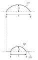
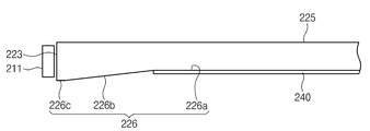
도 24는 본 발명의 일 실시예에 따른 반사판을 나타낸 단면도이다.24 is a cross-sectional view illustrating a reflector according to an exemplary embodiment of the present invention.
도 24를 참조하면, 상기 도광판(220)의 하측에는 반사판(240)이 구비된다. 구체적으로, 상기 반사판(240)은 상기 도광판(220)의 반사면(226) 중 제1 플랫면(226a)에 대응하는 위치에 구비되고, 상기 제1 플랫면(226a) 및 상기 출사면(225)과 평행한 평판 형태를 갖는다. 본 발명의 일 예로, 상기 반사판(240)은 반사율이 높은 알루미늄 재질의 시트로 이루어질 수 있다. 따라서, 상기 반사판(240)은 상기 제1 플랫면(226a)으로부터 누설되는 광을 반사하는 역할을 수행한다.Referring to FIG. 24, a reflecting
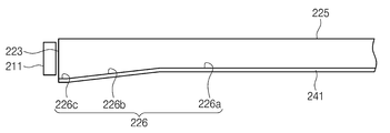
도 25는 본 발명의 다른 실시예에 따른 반사판을 나타낸 단면도이다.25 is a cross-sectional view illustrating a reflecting plate according to another exemplary embodiment of the present invention.
도 25를 참조하면, 본 발명의 다른 실시예에 따른 반사판(241)은 상기 도광판(220)의 제1 플랫면(226a), 경사면(226b) 및 제2 플랫면(226c)에 대응하는 위치에 구비되어, 상기 경사면(226b) 위치에서 경사진 구조를 갖는다. 따라서, 상기 반사판(241)은 상기 제1 플랫면(226a), 경사면(226b) 및 제2 플랫면(226c)으로부터 누설되는 광을 반사하는 역할을 수행한다.Referring to FIG. 25, the reflecting
도 26은 반사판 형상에 따른 입광부 영역의 휘도를 나타낸 그래프이다. 도 26에서, x축은 도광판(220)의 중앙부를 기준으로 입광부와 대광부의 위치를 나타내고, y축은 휘도를 나타낸다. 제20 그래프(G20)는 도 24에 도시된 반사판(240)을 채용한 경우의 휘도 분포를 나타내고, 제21 그래프(G21)는 도 25에 도시된 반사판(241)을 채용한 경우의 휘도 분포를 나타낸다.FIG. 26 is a graph illustrating luminance of a light incident region according to a shape of a reflector. In FIG. 26, the x axis represents the positions of the light incident portion and the light portion relative to the center portion of the
도 26에 도시된 바와 같이, 상기 반사판(241)이 상기 경사면(226b) 및 제2 플랫면(226c)까지 연장된 경우가 상기 반사판(240)이 상기 제1 플랫면(226a)에 형성된 경우보다 상기 입광부 영역에서의 휘도가 더 낮게 나타났다.As shown in FIG. 26, the
이로부터 알 수 있듯이, 상기 입광부 영역에서의 빛샘 현상을 억제하기 위하여 상기 반사판(241)은 제1 플랫면(226a), 경사면(226b) 및 제2 플랫면(226c)에 대응하는 위치에 구비될 수 있다.As can be seen from this, in order to suppress light leakage in the light incident region, the reflecting
도 27은 본 발명의 다른 실시예에 따른 도광판 및 반사판을 나타낸 단면도이다.27 is a cross-sectional view illustrating a light guide plate and a reflecting plate according to another exemplary embodiment of the present invention.
도 27을 참조하면, 상기 반사판(240)이 상기 도광판(220)의 제1 플랫면(226a)에 대응하여 구비되는 경우, 상기 도광판(220)의 경사면(226b)에 대응하는 부분은 확산 처리될 수 있다. 구체적으로, 상기 경사면(226b)이 형성된 영역에 산란제(228)를 형성하는 것과 같은 확산 처리를 실시하여, 상기 입광부 영역에서의 휘도 증가를 억제시킬 수 있다.Referring to FIG. 27, when the
이 경우, 상기 반사판(240)을 상기 경사면(226b) 및 제2 플랫면(226c)의 위치까지 연장시키지 않아도 빛샘 현상을 억제시킬 수 있다.In this case, the light leakage phenomenon can be suppressed without extending the
도 28은 도 1에 도시된 절단선 Ⅶ-Ⅶ`에 따라 절단한 단면도이다.FIG. 28 is a cross-sectional view taken along the cutting line VII-VII ′ of FIG. 1.
도 28을 참조하면, 상기 바텀 샤시(500)의 바닥부(502)에는 상기 백라이트 유닛(200)이 수납된다. 특히, 상기 바닥부(502), 측벽(504) 및 커버부(506)에 의해서 정의된 수납 공간에는 상기 광원부(210)가 수납된다. Referring to FIG. 28, the
상기 광원부(210)의 지지 필름(212)은 반사 테이프(215)에 의해서 상기 바텀 샤시(500)의 상기 바닥부(502)에 고정될 수 있다. 상기 반사 테이프(215)는 화이트 물질로 이루어져 상기 도광판(220)으로부터 누설된 광을 반사하는 역할도 수행할 수 있다.The
상기 바텀 샤시(500)에는 상기 광원부(210)과 상기 도광판(220)의 상기 입사면(223)이 인접하도록 상기 도광판(220)이 수납된다. 상기 도광판(220)과 상기 바닥부(502) 사이에는 반사판(240)이 개재된다. 상기 반사판(240)은 상기 도광판(220)의 상기 제1 플랫면(226a)에 대응하는 위치에 구비된다.The
상기 도광판(220) 상에는 광학 시트들(230)이 배치된다. 상기 광학 시트들(230)은 4매 시트로 이루어질 수 있다. 구체적으로, 상기 광학 시트들(230)은 1개의 확산시트, 2장의 프리즘 시트 및 보호 시트로 이루어질 수 있다.The
상기 바텀 샤시(500)의 상기 커버부(506)의 내측면에는 상기 도광판(220)의 비유효 출사영역(NAE)에 대응하여 상기 출사면(225)을 커버하는 반사 시트(250)가 더 구비될 수 있다. 상기 반사 시트(250)는 상기 비유효 출사 영역(NAE)에서 광이 새는 현상을 방지할 수 있다.The inner surface of the
상기 커버부(506) 상에는 상기 표시 패널(106)이 안착된다. 상기 표시 패널(106)을 상기 커버부(506)에 고정시키기 위해 상기 커버부(506)와 상기 표시 패널(106) 사이에는 양면 테이프(510)가 개재될 수 있다. 또한, 상기 양면 테이프(510)와 상기 표시 패널(106) 사이에는 상기 표시 패널(106)이 외부 충격에 의해서 파손되는 것을 방지하기 위한 완층 필름(520)이 더 개재될 수 있다.The
도 28에 도시된 바와 같이, 상기 바텀 샤시(500)의 상기 바닥부(502)는 상기 표시 패널(106) 측으로 소정의 깊이로 함몰되도록 형성될 수 있다. 상기 바닥부(502)가 함몰되기 시작하는 지점은 적어도 상기 제1 플랫면(226a)이 시작된 지점보다 상기 도광판(220)의 중앙부에 인접할 수 있다. 또한, 상기 바닥부(502)의 함몰 깊이는 상기 도광판(220)의 제1 두께(t1, 도 14에 도시됨)와 제2 두께(t2, 도 14에 도시됨)의 차이값에 대응하는 크기를 가질 수 있다.As illustrated in FIG. 28, the
상기 바닥부(502)가 함몰되는 것에 의해서 상기 바텀 샤시(500)의 배면에는 부품을 수납할 수 있는 부품 수납부(550)가 형성된다. 상기 부품 수납부(550)에는 배터리(600)와 같은 부품들이 수납될 수 있다.As the
따라서, 상기 배터리(600)와 같은 부품들에 의해서 상기 표시 장치(1000)의 전체적인 두께가 증가하는 것을 방지할 수 있다.Therefore, it is possible to prevent the overall thickness of the
도 29는 본 발명의 다른 실시예에 따른 표시 장치의 단면도이다. 도 29에 도시된 구성 요소 중 도 1 및 28에 도시된 구성 용소와 동일한 구성 요소에 대해서는 동일한 참조부호를 병기하고, 그에 대한 구체적인 설명은 생략한다.29 is a cross-sectional view of a display device according to another exemplary embodiment of the present invention. Of the components shown in FIG. 29, the same reference numerals are given to the same components as those shown in FIGS. 1 and 28, and detailed description thereof will be omitted.
도 29를 참조하면, 상기 바텀 샤시(500)의 바닥부(502)에는 상기 백라이트 유닛(200)이 수납된다. 특히, 상기 바닥부(502), 측벽(504) 및 커버부(506)에 의해서 정의된 수납 공간에는 광원부(215)가 수납된다. Referring to FIG. 29, the
본 발명의 다른 실시예에 따르면, 상기 광원부(215)는 지지 기판(214) 및 상기 지지 기판(214) 상에 실장된 다수의 발광 다이오드(213)를 포함한다. 상기 지지 기판(214)은 상기 다수의 발광 다이오드(213)가 실장되는 상면이 상기 도광판(220)의 입사면(223)에 나란하도록 배치된다.According to another embodiment of the present invention, the
상기 바텀 샤시(500)에는 상기 광원부(215)과 상기 도광판(220)의 상기 입사면(223)이 인접하도록 상기 도광판(220)이 수납된다. 상기 도광판(220)과 상기 바닥부(502) 사이에는 반사판(241)이 개재된다. The
상기 반사판(241)은 상기 도광판(220)의 제1 플랫면(226a), 경사면(226b) 및 제2 플랫면(226c)에 대응하는 위치에 구비되어, 상기 경사면(226b) 위치에서 경사진 구조를 갖는다. 따라서, 상기 반사판(241)은 상기 제1 플랫면(226a), 경사면(226b) 및 제2 플랫면(226c)으로부터 누설되는 광을 반사하는 역할을 수행한다.The
도 29에 도시된 바와 같이, 상기 바텀 샤시(500)의 상기 바닥부(502)는 상기 표시 패널(106) 측으로 소정의 깊이로 함몰되어 상기 바텀 샤시(500)의 배면에는 부품을 수납할 수 있는 부품 수납부(550)가 형성된다. 상기 부품 수납부(550)에는 배터리(600)와 같은 부품들이 수납될 수 있다. 따라서, 상기 배터리(600)와 같은 부품들에 의해서 상기 표시 장치(1000)의 전체적인 두께가 증가하는 것을 방지할 수 있다.As illustrated in FIG. 29, the
도 30은 본 발명의 다른 실시예에 따른 백라이트 유닛의 평면도이고, 도 31은 도 30에 도시된 절단선 Ⅷ-Ⅷ`에 따라 절단한 단면도이다. 30 is a plan view of a backlight unit according to another exemplary embodiment of the present invention, and FIG. 31 is a cross-sectional view taken along the line VII- ′ ′ of FIG. 30.
도 30 및 도 31을 참조하면, 본 발명의 다른 실시예에 따른 백라이트 유닛은 도광판(220의 제3 측면(223)에 인접하여 구비되는 다수의 제1 발광 다이오드(211) 및 상기 도광판(220)의 제4 측면(224)에 인접하여 구비되는 다수의 제2 발광 다이오드(213)를 포함한다. 여기서, 상기 제3 측면(223)은 제1 입사면으로 정의되고, 상기 제4 측면(224)은 제2 입사면으로 정의될 수 있다.30 and 31, a backlight unit according to another embodiment of the present invention includes a plurality of first
본 발명의 다른 실시예에 따르면, 상기 도광판(220)의 출사면(225)은 상기 제1 입사면(223)으로부터 순차적으로 인접하는 제1 영역(A1), 제2 영역(A2) 및 제3 영역(A3)으로 구분될 수 있다. 상기 제2 영역(A2)은 제1 렌티 영역(RA1), 제2 렌티 영역(RA2) 및 제3 렌티 영역(RA3)을 포함할 수 있다.According to another embodiment of the present invention, the
상기 제1 렌티 영역(RA1)은 상기 제1 영역(A1)과 인접하는 영역이며, 상기 제3 렌티 영역(RA3)은 상기 제3 영역(A3)과 인접하는 영역이며, 상기 제2 렌티 영역(RA2)은 상기 제1 및 제3 렌티 영역(RA1, RA3) 사이에 위치한다.The first lenti area RA1 is an area adjacent to the first region A1, and the third lenti area RA3 is an area adjacent to the third area A3, and the second lenti area ( RA2) is located between the first and third lenti regions RA1 and RA3.
상기 도광판(220)은 상기 제2 영역(A2)에 형성된 돌출부(227)를 포함한다. 구체적으로, 상기 돌출부(227)는 상기 제1 및 제3 영역(A1, A3)에는 형성되지 않는다.The
본 발명의 일 예로, 상기 돌출부(227)는 상기 제1 렌티 영역(RA1) 및 상기 제3 렌티 영역(RA3)에서 반원뿔 형상을 갖고, 상기 제2 렌티 영역(RA2)에서 반원기둥 형상을 갖는다.As an example, the
즉, 상기 제1 렌티 영역(RA1)에서 상기 돌출부(227)의 높이는 상기 제1 입사면(223)으로부터 멀어질수록 증가하고, 상기 돌출부(227)의 직경도 상기 제1 입사면(223)으로부터 멀어질수록 증가한다. 또한, 상기 제3 렌티 영역(RA3)에서 상기 돌출부(227)의 높이는 상기 제2 입사면(224)으로부터 멀어질수록 증가하고, 상기 돌출부(227)의 직경도 상기 제2 입사면(224)으로부터 멀어질수록 증가한다. 한편, 상기 제2 렌티 영역(RA2)에서 상기 돌출부(227)의 높이 및 직경은 일정한 값을 유지한다.That is, the height of the
이밖에 상기 돌출부(227)의 형상 및 크기는 앞서 도면을 참조하여 설명한 내용과 중복되므로, 이하에서는 구체적인 설명은 생략하기로 한다.In addition, since the shape and size of the
본 발명의 다른 실시예에 따르면, 상기 도광판(220)의 반사면(226)은 상기 출사면(225)과 평행한 제1 플랫면(226a), 상기 제1 입사면(223)에 인접하고 상기 출사면(225) 측으로 기울어진 제1 경사면(226b), 상기 제1 경사면(226b)과 상기 제1 입사면(223)을 연결하는 제2 플랫면(226c), 상기 제2 입사면(224)에 인접하고 상기 출사면(225) 측으로 기울어진 제2 경사면(226e), 상기 제2 경사면(226e)과 상기 제2 입사면(224)을 연결하는 제3 플랫면(226f)으로 이루어진다. According to another embodiment of the present invention, the
상기 제1 경사면(226b)은 상기 제1 입사면(223) 측으로 갈수록 상기 출사면(225)으로부터 멀어지는 방향으로 기울어진다. 상기 제2 플랫면(226c)은 상기 제1 경사면(226b)과 상기 입사면(223) 사이에서 상기 출사면(225)과 평행하게 구비된다.The first
상기 제2 경사면(226e)은 상기 제2 입사면(224) 측으로 갈수록 상기 출사면(225)으로부터 멀어지는 방향으로 기울어진다. 상기 제3 플랫면(226f)은 상기 제2 경사면(226e)과 상기 제2 입사면(224) 사이에서 상기 출사면(225)과 평행하게 구비된다.The second
상기 제1 및 제2 경사면(226b, 226e)은 앞서 기술한 경사면(226b)과 유사한 형태로 형성되므로, 이하에서는 상기 제1 및 제2 경사면(226a, 226e)에 대한 구체적인 설명은 생략한다.Since the first and second
이상, 첨부된 도면을 참조하여 본 발명의 실시예를 설명하였지만, 본 발명이 속하는 기술분야에서 통상의 지식을 가진 자는 본 발명이 그 기술적 사상이나 필수적인 특징으로 변경하지 않고서 다른 구체적인 형태로 실시될 수 있다는 것을 이해할 수 있을 것이다. 그러므로 이상에서 기술한 실시예에는 모든 면에서 예시적인 것이며 한정적이 아닌 것으로 이해해야만 한다.While the present invention has been described in connection with what is presently considered to be practical exemplary embodiments, it is to be understood that the invention is not limited to the disclosed embodiments, but, on the contrary, It will be understood. It is therefore to be understood that the above-described embodiments are illustrative and not restrictive in every respect.
1000: 표시 장치 100: 표시 유닛
200: 백라이트 유닛 300: 탑 샤시
400: 몰드 프레임 500: 바텀 샤시1000: display device 100: display unit
200: backlight unit 300: top chassis
400: mold frame 500: bottom chassis
Claims (30)
상기 광을 수신하는 입사면, 상기 입사면을 통해 입사된 광을 출사하는 출사면, 상기 출사면과 마주하고, 상기 입사된 광을 반사하는 반사면, 및 상기 출사면 상에 렌티큘러 형상으로 제공된 돌출부를 구비하는 도광판을 포함하고,
상기 반사면은 상기 입사면에 인접하고 상기 출사면 측으로 기울어진 경사면을 구비하는 것을 특징으로 하는 백라이트 유닛.A light source for generating light; And
An entrance surface for receiving the light, an emission surface for emitting light incident through the entrance surface, a reflection surface facing the emission surface and reflecting the incident light, and a protrusion provided in a lenticular shape on the emission surface Including a light guide plate having a,
And the reflective surface has an inclined surface adjacent to the incident surface and inclined toward the exit surface.
상기 돌출부는 상기 제2 영역에 제공되는 것을 특징으로 하는 백라이트 유닛.The method of claim 1, wherein the emission surface is divided into first and second regions sequentially adjacent to the incident surface,
And the protrusion is provided in the second area.
상기 a 및 b는

을 만족하고,
상기 θ는 0.03°보다 작은 것을 특징으로 하는 백라이트 유닛.The method of claim 5, wherein when the width of the first lenti region in the second direction is defined as a, and the maximum height of the protrusion in the first lenti region is defined as b,
A and b are
Lt; / RTI >
And wherein θ is less than 0.03 °.
상기 입사면 측으로 갈수록 상기 출사면에서 멀어지는 방향으로 기울어진 것을 특징으로 하는 백라이트 유닛.3. The width of the first region (the length of the incidence surface) according to claim 2, wherein the width of the region where the inclined surface is formed (a vertical distance from the point where the inclined surface starts to the point where the inclined surface ends) is determined based on the incidence surface. Width in a direction perpendicular to the direction)
The backlight unit, characterized in that inclined in a direction away from the exit surface toward the incident surface side.
상기 입사면과 상기 돌출부는 상기 제1 영역의 폭만큼 이격되며, 상기 제1 영역은 상기 비유효광 출사 영역 내에 포함되는 것을 특징으로 하는 백라이트 유닛.10. The method of claim 9, wherein the emission surface of the light guide plate is divided into an effective light emitting area and an ineffective light emitting area,
And the incident surface and the protrusion are spaced apart by the width of the first region, and the first region is included in the ineffective light emitting region.
상기 제2 영역에서 상기 반사 패턴은 상기 발광 다이오드에 대응하는 영역보다 서로 인접하는 두 개의 발광 다이오드 사이의 영역에서 낮은 밀도를 갖는 것을 특징으로 하는 백라이트 유닛.The method of claim 13, wherein the light source comprises a plurality of light emitting diodes arranged along the longitudinal direction of the incident surface,
And the reflective pattern in the second region has a lower density in a region between two light emitting diodes adjacent to each other than a region corresponding to the light emitting diode.
상기 표시 유닛으로 광을 제공하는 백라이트 유닛; 및
상기 백라이트 유닛을 수납하는 수납 용기를 포함하고,
상기 백라이트 유닛은,
광을 발생하는 광원; 및
상기 광을 수신하는 입사면, 상기 입사면을 통해 입사된 광을 출사하는 출사면, 상기 출사면과 마주하고, 상기 입사된 광을 반사하는 반사면, 및 상기 출사면 상에 렌티큘러 형상으로 제공된 돌출부를 구비하는 도광판을 포함하고,
상기 반사면은 상기 입사면에 인접하고 상기 출사면 측으로 기울어진 경사면을 구비하는 것을 특징으로 하는 표시 장치.A display unit for displaying an image;
A backlight unit providing light to the display unit; And
A storage container for storing the backlight unit,
The backlight unit includes:
A light source for generating light; And
An entrance surface for receiving the light, an emission surface for emitting light incident through the entrance surface, a reflection surface facing the emission surface and reflecting the incident light, and a protrusion provided in a lenticular shape on the emission surface Including a light guide plate having a,
And the reflective surface has an inclined surface adjacent to the incident surface and inclined toward the exit surface.
상기 돌출부는 상기 제2 영역에 구비되는 것을 특징으로 하는 표시 장치.20. The method of claim 19, wherein the exit surface is divided into first and second regions sequentially adjacent to the incident surface,
And the protrusion is provided in the second area.
상기 제1 렌티 영역에서 상기 돌출부의 높이는 상기 입사면으로부터 멀어질수록 증가하는 것을 특징으로 하는 표시 장치.21. The method of claim 20, wherein the second region is the first lentil region and the protrusion having a semi-conical shape in which the protrusion extends in a direction perpendicular to the longitudinal direction (first direction) of the incident surface (second direction). A second lenti region having a semi-cylindrical shape extending in a direction perpendicular to the longitudinal direction of the incident surface;
And the height of the protrusion increases in the first lenient area away from the incident surface.
상기 a 및 b는

을 만족하고,
상기 θ는 0.03°보다 작은 것을 특징으로 하는 표시 장치.The method of claim 21, wherein when the width of the first lenti region in the second direction is defined as a, and the maximum height of the protrusion in the first lenti region is defined as b,
A and b are
Lt; / RTI >
Wherein θ is smaller than 0.03 °.
상기 입사면 측으로 갈수록 상기 출사면에서 멀어지는 방향으로 기울어지며,
상기 경사면의 경사 각도는 2° 내지 5°인 것을 특징으로 하는 표시 장치.21. The width of the first region of claim 20, wherein the width of the region where the inclined surface is formed (the vertical distance from the point where the inclined surface starts to the point where the inclined surface ends) is determined based on the incidence surface. Width in a direction perpendicular to the direction)
It is inclined in a direction away from the exit surface toward the incident surface side,
And an inclination angle of the inclined surface is 2 ° to 5 °.
상기 입사면과 상기 돌출부는 상기 제1 영역의 폭만큼 이격되며, 상기 제1 영역은 상기 비유효광 출사 영역 내에 포함되는 것을 특징으로 하는 표시 장치.The method of claim 23, wherein the light emitting plate is divided into an effective light emitting area and an ineffective light emitting area,
And the incident surface and the protrusion are spaced apart from each other by the width of the first region, and the first region is included in the ineffective light emitting region.
상기 제2 영역에서 상기 반사 패턴은 상기 발광 다이오드에 대응하는 영역보다 서로 인접하는 두 개의 발광 다이오드 사이의 영역에서 낮은 밀도를 갖는 것을 특징으로 하는 표시 장치.The light source of claim 25, wherein the light source includes a plurality of light emitting diodes arranged along a length direction of the incident surface.
And the reflection pattern in the second area has a lower density in a region between two light emitting diodes adjacent to each other than a region corresponding to the light emitting diode.
상기 도광판은 상기 경사부에 대응하여 형성된 산란제를 더 포함하는 것을 특징으로 하는 표시 장치.The method of claim 27, wherein the reflecting plate has a flat plate shape parallel to the exit surface,
The light guide plate further comprises a scattering agent formed corresponding to the inclined portion.
상기 백라이트 유닛이 안착되는 바닥부;
상기 바닥부로부터 연장된 측벽; 및
상기 측벽으로부터 상기 바닥부와 평행하게 연장되어 상기 광원을 커버하는 커버부를 포함하는 것을 특징으로 하는 표시 장치.The method of claim 19, wherein the storage container,
A bottom part on which the backlight unit is mounted;
Sidewalls extending from the bottom portion; And
And a cover part extending in parallel with the bottom part from the side wall to cover the light source.
Priority Applications (5)
| Application Number | Priority Date | Filing Date | Title |
|---|---|---|---|
| KR1020120085384A KR20140018742A (en) | 2012-08-03 | 2012-08-03 | Backlight unit and display apparatus having the same |
| US13/755,327 US9291765B2 (en) | 2012-08-03 | 2013-01-31 | Backlight unit and display apparatus having the same |
| EP13157367.7A EP2693115A3 (en) | 2012-08-03 | 2013-03-01 | Backlight unit and display apparatus having the same |
| CN201310180686.2A CN103576381B (en) | 2012-08-03 | 2013-05-16 | Back light unit and display device with the back light unit |
| JP2013112543A JP6178114B2 (en) | 2012-08-03 | 2013-05-29 | Backlight unit and display device having the same |
Applications Claiming Priority (1)
| Application Number | Priority Date | Filing Date | Title |
|---|---|---|---|
| KR1020120085384A KR20140018742A (en) | 2012-08-03 | 2012-08-03 | Backlight unit and display apparatus having the same |
Related Child Applications (1)
| Application Number | Title | Priority Date | Filing Date |
|---|---|---|---|
| KR1020190099412A Division KR102150855B1 (en) | 2019-08-14 | 2019-08-14 | Backlight unit and display apparatus having the same |
Publications (1)
| Publication Number | Publication Date |
|---|---|
| KR20140018742A true KR20140018742A (en) | 2014-02-13 |
Family
ID=47844094
Family Applications (1)
| Application Number | Title | Priority Date | Filing Date |
|---|---|---|---|
| KR1020120085384A KR20140018742A (en) | 2012-08-03 | 2012-08-03 | Backlight unit and display apparatus having the same |
Country Status (5)
| Country | Link |
|---|---|
| US (1) | US9291765B2 (en) |
| EP (1) | EP2693115A3 (en) |
| JP (1) | JP6178114B2 (en) |
| KR (1) | KR20140018742A (en) |
| CN (1) | CN103576381B (en) |
Cited By (3)
| Publication number | Priority date | Publication date | Assignee | Title |
|---|---|---|---|---|
| US9759853B2 (en) | 2014-10-14 | 2017-09-12 | Samsung Display Co., Ltd. | Backlight unit and display apparatus having the same |
| US9927570B2 (en) | 2015-02-24 | 2018-03-27 | Samsung Display Co., Ltd. | Liquid crystal display apparatus having a light guide plate with optical patterns to prevent light leakage |
| CN114624811A (en) * | 2022-05-17 | 2022-06-14 | 深圳市北泰显示技术有限公司 | Production method of display screen backlight module |
Families Citing this family (17)
| Publication number | Priority date | Publication date | Assignee | Title |
|---|---|---|---|---|
| JP5949465B2 (en) * | 2012-11-05 | 2016-07-06 | オムロン株式会社 | Transfer molding method, mold structure, transfer molding apparatus, and optical member |
| KR102049856B1 (en) * | 2013-02-21 | 2019-11-28 | 엘지전자 주식회사 | Display device |
| CN105698045A (en) * | 2014-11-28 | 2016-06-22 | 江苏欧密格光电科技股份有限公司 | High-reflectance LED backlight plate |
| JP6542184B2 (en) | 2016-12-01 | 2019-07-10 | ミネベアミツミ株式会社 | Planar lighting device |
| CN110168280A (en) * | 2016-12-28 | 2019-08-23 | 镭亚股份有限公司 | Multi-view display with reflective support structure |
| JP6949643B2 (en) * | 2017-09-28 | 2021-10-13 | 株式会社ジャパンディスプレイ | Lighting device and display device |
| JP2021518637A (en) * | 2018-03-22 | 2021-08-02 | リアルディー スパーク エルエルシー | Optical waveguide for directional backlight |
| EP3814832A4 (en) | 2018-06-29 | 2022-04-06 | RealD Spark, LLC | Stabilization for privacy display |
| WO2020018552A1 (en) | 2018-07-18 | 2020-01-23 | Reald Spark, Llc | Optical stack for switchable directional display |
| WO2020054017A1 (en) * | 2018-09-13 | 2020-03-19 | 堺ディスプレイプロダクト株式会社 | Liquid crystal display device |
| TW202102883A (en) | 2019-07-02 | 2021-01-16 | 美商瑞爾D斯帕克有限責任公司 | Directional display apparatus |
| KR20220098382A (en) | 2019-11-13 | 2022-07-12 | 리얼디 스파크, 엘엘씨 | Off-axis display device |
| WO2021118936A1 (en) | 2019-12-10 | 2021-06-17 | Reald Spark, Llc | Control of reflections of a display device |
| EP4143041A1 (en) | 2020-04-30 | 2023-03-08 | RealD Spark, LLC | Directional display apparatus |
| TW202204818A (en) | 2020-07-29 | 2022-02-01 | 美商瑞爾D斯帕克有限責任公司 | Pupillated illumination apparatus |
| US11892717B2 (en) | 2021-09-30 | 2024-02-06 | Reald Spark, Llc | Marks for privacy display |
| WO2023196440A1 (en) | 2022-04-07 | 2023-10-12 | Reald Spark, Llc | Directional display apparatus |
Family Cites Families (37)
| Publication number | Priority date | Publication date | Assignee | Title |
|---|---|---|---|---|
| JPH0963332A (en) * | 1995-08-21 | 1997-03-07 | Minebea Co Ltd | Sheet-like light source device |
| US5854872A (en) * | 1996-10-08 | 1998-12-29 | Clio Technologies, Inc. | Divergent angle rotator system and method for collimating light beams |
| US7001058B2 (en) | 2001-05-16 | 2006-02-21 | Ben-Zion Inditsky | Ultra-thin backlight |
| CN100392491C (en) * | 2001-07-27 | 2008-06-04 | 株式会社恩普乐 | Surface light source device and light guide plate |
| JP4049624B2 (en) * | 2001-07-27 | 2008-02-20 | 株式会社エンプラス | Surface light source device, image display device, and light guide plate |
| JP2003121840A (en) | 2001-10-10 | 2003-04-23 | Kawaguchiko Seimitsu Co Ltd | Liquid crystal display device |
| US7128459B2 (en) * | 2001-11-12 | 2006-10-31 | Nidec Copal Corporation | Light-guide plate and method for manufacturing the same |
| KR100756368B1 (en) | 2002-12-05 | 2007-09-10 | 삼성전자주식회사 | Back light assembly and liquid crystal display having the same |
| JP2005063913A (en) * | 2003-08-20 | 2005-03-10 | Toyota Industries Corp | Light guide plate |
| KR20050030723A (en) | 2003-09-26 | 2005-03-31 | 삼성전자주식회사 | Back light assembly and liquid crystal display having the same |
| KR20050049196A (en) | 2003-11-21 | 2005-05-25 | 삼성전자주식회사 | Back light assembly and liquid crystal display having the same |
| KR20090015997A (en) * | 2004-09-28 | 2009-02-12 | 미츠비시 레이온 가부시키가이샤 | Surface light guide |
| JP4728688B2 (en) * | 2004-10-13 | 2011-07-20 | Nec液晶テクノロジー株式会社 | Light source device, display device, terminal device, and optical unit |
| JP2006133274A (en) | 2004-11-02 | 2006-05-25 | Sony Corp | Liquid crystal display device |
| JP2006154320A (en) | 2004-11-30 | 2006-06-15 | Citizen Watch Co Ltd | Display device and lighting device |
| KR20060132202A (en) * | 2005-06-17 | 2006-12-21 | 삼성전자주식회사 | Liquid crystal display apparatus |
| JP4329736B2 (en) * | 2005-07-04 | 2009-09-09 | セイコーエプソン株式会社 | Optical substrate, planar illumination device, electro-optical device |
| CN100498389C (en) * | 2006-03-25 | 2009-06-10 | 鸿富锦精密工业(深圳)有限公司 | Light conducting plate and back light module |
| JP5142499B2 (en) | 2006-08-18 | 2013-02-13 | 株式会社ジャパンディスプレイイースト | Liquid crystal display |
| US7287892B1 (en) * | 2006-10-30 | 2007-10-30 | Avago Technologies Ecbu Ip (Singapore) Pte Ltd | Light source for back-lit displays |
| KR101149409B1 (en) * | 2006-11-09 | 2012-06-01 | 삼성전자주식회사 | A back light unit |
| JP2008134391A (en) | 2006-11-28 | 2008-06-12 | Optrex Corp | Liquid crystal display device |
| KR20080060736A (en) | 2006-12-27 | 2008-07-02 | 삼성전자주식회사 | Back-light assembly and liquid crystal display device having the same |
| JP2008170739A (en) | 2007-01-12 | 2008-07-24 | Hitachi Displays Ltd | Liquid crystal display device |
| WO2009004598A2 (en) * | 2007-07-05 | 2009-01-08 | Udayan Kanade | Light source of varying thickness |
| JP5202906B2 (en) * | 2007-08-27 | 2013-06-05 | 株式会社ジャパンディスプレイイースト | Liquid crystal display |
| KR100942490B1 (en) * | 2007-09-05 | 2010-02-12 | 제일모직주식회사 | Light guide panel for LCD back light unit and LCD back light unit thereby |
| KR101502368B1 (en) | 2007-11-27 | 2015-03-13 | 엘지디스플레이 주식회사 | Backlight unit and liquid cristal display device usimg the same |
| JP2011512006A (en) * | 2008-01-30 | 2011-04-14 | デジタル オプティクス インターナショナル,リミティド ライアビリティ カンパニー | Thin lighting system |
| US8662727B2 (en) * | 2008-03-19 | 2014-03-04 | I2Ic Corporation | Apparatus for efficiently coupling light from a light source into a thin object |
| US8089583B2 (en) * | 2008-06-18 | 2012-01-03 | Jabil Circuit, Inc. | Light guide blade with color balancing structures and blue absorption compensation for large screen LED backlight unit |
| WO2010004745A1 (en) | 2008-07-10 | 2010-01-14 | オムロン株式会社 | Surface light source device and liquid crystal display device |
| DE102008051208A1 (en) | 2008-10-14 | 2010-04-15 | Khs Ag | Carrying handle for a container |
| JP4985787B2 (en) | 2010-01-12 | 2012-07-25 | オムロン株式会社 | Surface light source device and liquid crystal display device |
| JP2011187230A (en) * | 2010-03-05 | 2011-09-22 | Omron Corp | Surface light source device and liquid crystal display device |
| TWI497015B (en) * | 2010-05-27 | 2015-08-21 | Hon Hai Prec Ind Co Ltd | Backlight module |
| KR20130019974A (en) * | 2011-08-18 | 2013-02-27 | 삼성디스플레이 주식회사 | Back-light unit and display device having the same |
-
2012
- 2012-08-03 KR KR1020120085384A patent/KR20140018742A/en not_active Application Discontinuation
-
2013
- 2013-01-31 US US13/755,327 patent/US9291765B2/en not_active Expired - Fee Related
- 2013-03-01 EP EP13157367.7A patent/EP2693115A3/en not_active Withdrawn
- 2013-05-16 CN CN201310180686.2A patent/CN103576381B/en not_active Expired - Fee Related
- 2013-05-29 JP JP2013112543A patent/JP6178114B2/en not_active Expired - Fee Related
Cited By (3)
| Publication number | Priority date | Publication date | Assignee | Title |
|---|---|---|---|---|
| US9759853B2 (en) | 2014-10-14 | 2017-09-12 | Samsung Display Co., Ltd. | Backlight unit and display apparatus having the same |
| US9927570B2 (en) | 2015-02-24 | 2018-03-27 | Samsung Display Co., Ltd. | Liquid crystal display apparatus having a light guide plate with optical patterns to prevent light leakage |
| CN114624811A (en) * | 2022-05-17 | 2022-06-14 | 深圳市北泰显示技术有限公司 | Production method of display screen backlight module |
Also Published As
| Publication number | Publication date |
|---|---|
| EP2693115A2 (en) | 2014-02-05 |
| JP6178114B2 (en) | 2017-08-09 |
| US20140036531A1 (en) | 2014-02-06 |
| CN103576381B (en) | 2018-09-21 |
| US9291765B2 (en) | 2016-03-22 |
| JP2014032953A (en) | 2014-02-20 |
| CN103576381A (en) | 2014-02-12 |
| EP2693115A3 (en) | 2018-02-07 |
Similar Documents
| Publication | Publication Date | Title |
|---|---|---|
| KR20140018742A (en) | Backlight unit and display apparatus having the same | |
| US7641376B2 (en) | Surface light source device and display device using same | |
| JP4544531B2 (en) | Surface light source device | |
| KR101098338B1 (en) | Optic package, optic lens and backlight assembly and display device having the optic package | |
| JP4856037B2 (en) | Surface lighting device | |
| TWI336799B (en) | Light guide device and light guide plate using the same | |
| JP5295382B2 (en) | Planar light source device and display device using the same | |
| KR20190079727A (en) | Display device | |
| KR20110124157A (en) | Planar lighting device | |
| CN112558213A (en) | Illumination device and display device | |
| KR20080085242A (en) | Light guide plate and blacklight assembly using the same | |
| JP2011150832A (en) | Planar lighting device and method for manufacturing the same | |
| US8690409B2 (en) | Backlight assembly and display apparatus having the same | |
| JP2004179062A (en) | Illuminating device, photo conductive material and liquid crystal display | |
| KR20150001097A (en) | Backlight assembly and display apparatus having the same | |
| US7139464B2 (en) | Surface light source and light guide used therefor | |
| KR20150072515A (en) | Backlight unit and display apparatus having the same | |
| KR20130104560A (en) | Backlight assembly and display device comprising the same | |
| US10718973B2 (en) | Display device | |
| KR102075922B1 (en) | Light Guide Panel and Liquid Display Apparatus using the same | |
| KR102150855B1 (en) | Backlight unit and display apparatus having the same | |
| JP4075977B2 (en) | Surface light source device and image display device including the surface light source device | |
| KR20140102793A (en) | Backlight assembly and display device comprising the same | |
| US10877204B2 (en) | Illumination device and display apparatus | |
| JP5184296B2 (en) | Light guide plate unit and liquid crystal display device |
Legal Events
| Date | Code | Title | Description |
|---|---|---|---|
| A201 | Request for examination | ||
| E902 | Notification of reason for refusal | ||
| E601 | Decision to refuse application | ||
| E601 | Decision to refuse application | ||
| E801 | Decision on dismissal of amendment |