KR20140001985A - Lighting diaphragm - Google Patents
Lighting diaphragm Download PDFInfo
- Publication number
- KR20140001985A KR20140001985A KR1020137019247A KR20137019247A KR20140001985A KR 20140001985 A KR20140001985 A KR 20140001985A KR 1020137019247 A KR1020137019247 A KR 1020137019247A KR 20137019247 A KR20137019247 A KR 20137019247A KR 20140001985 A KR20140001985 A KR 20140001985A
- Authority
- KR
- South Korea
- Prior art keywords
- light
- aperture
- filter
- illumination
- region
- Prior art date
Links
- 238000005286 illumination Methods 0.000 claims abstract description 47
- 230000005284 excitation Effects 0.000 claims abstract description 42
- 239000000758 substrate Substances 0.000 claims abstract description 17
- 230000005540 biological transmission Effects 0.000 claims abstract description 14
- 238000002073 fluorescence micrograph Methods 0.000 claims abstract description 12
- 239000000126 substance Substances 0.000 claims abstract description 9
- 230000003287 optical effect Effects 0.000 claims description 12
- 238000000034 method Methods 0.000 claims description 11
- 238000003384 imaging method Methods 0.000 claims description 8
- 239000012466 permeate Substances 0.000 claims 1
- 239000000463 material Substances 0.000 description 21
- MOFVSTNWEDAEEK-UHFFFAOYSA-M indocyanine green Chemical compound [Na+].[O-]S(=O)(=O)CCCCN1C2=CC=C3C=CC=CC3=C2C(C)(C)C1=CC=CC=CC=CC1=[N+](CCCCS([O-])(=O)=O)C2=CC=C(C=CC=C3)C3=C2C1(C)C MOFVSTNWEDAEEK-UHFFFAOYSA-M 0.000 description 15
- 229960004657 indocyanine green Drugs 0.000 description 15
- 235000012489 doughnuts Nutrition 0.000 description 9
- 238000002834 transmittance Methods 0.000 description 5
- 206010028980 Neoplasm Diseases 0.000 description 4
- 238000002428 photodynamic therapy Methods 0.000 description 4
- 230000015572 biosynthetic process Effects 0.000 description 3
- 230000000903 blocking effect Effects 0.000 description 3
- 239000000835 fiber Substances 0.000 description 3
- 239000004925 Acrylic resin Substances 0.000 description 2
- 229920000178 Acrylic resin Polymers 0.000 description 2
- 102000001554 Hemoglobins Human genes 0.000 description 2
- 108010054147 Hemoglobins Proteins 0.000 description 2
- 238000003745 diagnosis Methods 0.000 description 2
- 238000010586 diagram Methods 0.000 description 2
- 239000005357 flat glass Substances 0.000 description 2
- 238000001727 in vivo Methods 0.000 description 2
- 239000010409 thin film Substances 0.000 description 2
- 238000007740 vapor deposition Methods 0.000 description 2
- XLYOFNOQVPJJNP-UHFFFAOYSA-N water Substances O XLYOFNOQVPJJNP-UHFFFAOYSA-N 0.000 description 2
- UJKPHYRXOLRVJJ-MLSVHJFASA-N CC(O)C1=C(C)/C2=C/C3=N/C(=C\C4=C(CCC(O)=O)C(C)=C(N4)/C=C4\N=C(\C=C\1/N\2)C(C)=C4C(C)O)/C(CCC(O)=O)=C3C Chemical class CC(O)C1=C(C)/C2=C/C3=N/C(=C\C4=C(CCC(O)=O)C(C)=C(N4)/C=C4\N=C(\C=C\1/N\2)C(C)=C4C(C)O)/C(CCC(O)=O)=C3C UJKPHYRXOLRVJJ-MLSVHJFASA-N 0.000 description 1
- MYMOFIZGZYHOMD-UHFFFAOYSA-N Dioxygen Chemical compound O=O MYMOFIZGZYHOMD-UHFFFAOYSA-N 0.000 description 1
- 238000010521 absorption reaction Methods 0.000 description 1
- 238000009825 accumulation Methods 0.000 description 1
- 239000003153 chemical reaction reagent Substances 0.000 description 1
- 239000002872 contrast media Substances 0.000 description 1
- 238000002405 diagnostic procedure Methods 0.000 description 1
- 238000007598 dipping method Methods 0.000 description 1
- 235000013305 food Nutrition 0.000 description 1
- 239000011521 glass Substances 0.000 description 1
- 229910052736 halogen Inorganic materials 0.000 description 1
- 150000002367 halogens Chemical class 0.000 description 1
- 230000001678 irradiating effect Effects 0.000 description 1
- 239000005304 optical glass Substances 0.000 description 1
- 230000035699 permeability Effects 0.000 description 1
- 230000035945 sensitivity Effects 0.000 description 1
- 238000004544 sputter deposition Methods 0.000 description 1
- 230000001360 synchronised effect Effects 0.000 description 1
- 230000009466 transformation Effects 0.000 description 1
- 210000004881 tumor cell Anatomy 0.000 description 1
- 229910052724 xenon Inorganic materials 0.000 description 1
- FHNFHKCVQCLJFQ-UHFFFAOYSA-N xenon atom Chemical compound [Xe] FHNFHKCVQCLJFQ-UHFFFAOYSA-N 0.000 description 1
Images


Classifications
-
- F—MECHANICAL ENGINEERING; LIGHTING; HEATING; WEAPONS; BLASTING
- F21—LIGHTING
- F21V—FUNCTIONAL FEATURES OR DETAILS OF LIGHTING DEVICES OR SYSTEMS THEREOF; STRUCTURAL COMBINATIONS OF LIGHTING DEVICES WITH OTHER ARTICLES, NOT OTHERWISE PROVIDED FOR
- F21V13/00—Producing particular characteristics or distribution of the light emitted by means of a combination of elements specified in two or more of main groups F21V1/00 - F21V11/00
- F21V13/02—Combinations of only two kinds of elements
-
- A—HUMAN NECESSITIES
- A61—MEDICAL OR VETERINARY SCIENCE; HYGIENE
- A61B—DIAGNOSIS; SURGERY; IDENTIFICATION
- A61B1/00—Instruments for performing medical examinations of the interior of cavities or tubes of the body by visual or photographical inspection, e.g. endoscopes; Illuminating arrangements therefor
- A61B1/04—Instruments for performing medical examinations of the interior of cavities or tubes of the body by visual or photographical inspection, e.g. endoscopes; Illuminating arrangements therefor combined with photographic or television appliances
- A61B1/043—Instruments for performing medical examinations of the interior of cavities or tubes of the body by visual or photographical inspection, e.g. endoscopes; Illuminating arrangements therefor combined with photographic or television appliances for fluorescence imaging
-
- A—HUMAN NECESSITIES
- A61—MEDICAL OR VETERINARY SCIENCE; HYGIENE
- A61B—DIAGNOSIS; SURGERY; IDENTIFICATION
- A61B1/00—Instruments for performing medical examinations of the interior of cavities or tubes of the body by visual or photographical inspection, e.g. endoscopes; Illuminating arrangements therefor
- A61B1/06—Instruments for performing medical examinations of the interior of cavities or tubes of the body by visual or photographical inspection, e.g. endoscopes; Illuminating arrangements therefor with illuminating arrangements
- A61B1/0638—Instruments for performing medical examinations of the interior of cavities or tubes of the body by visual or photographical inspection, e.g. endoscopes; Illuminating arrangements therefor with illuminating arrangements providing two or more wavelengths
-
- A—HUMAN NECESSITIES
- A61—MEDICAL OR VETERINARY SCIENCE; HYGIENE
- A61B—DIAGNOSIS; SURGERY; IDENTIFICATION
- A61B1/00—Instruments for performing medical examinations of the interior of cavities or tubes of the body by visual or photographical inspection, e.g. endoscopes; Illuminating arrangements therefor
- A61B1/06—Instruments for performing medical examinations of the interior of cavities or tubes of the body by visual or photographical inspection, e.g. endoscopes; Illuminating arrangements therefor with illuminating arrangements
- A61B1/0646—Instruments for performing medical examinations of the interior of cavities or tubes of the body by visual or photographical inspection, e.g. endoscopes; Illuminating arrangements therefor with illuminating arrangements with illumination filters
-
- A—HUMAN NECESSITIES
- A61—MEDICAL OR VETERINARY SCIENCE; HYGIENE
- A61B—DIAGNOSIS; SURGERY; IDENTIFICATION
- A61B1/00—Instruments for performing medical examinations of the interior of cavities or tubes of the body by visual or photographical inspection, e.g. endoscopes; Illuminating arrangements therefor
- A61B1/06—Instruments for performing medical examinations of the interior of cavities or tubes of the body by visual or photographical inspection, e.g. endoscopes; Illuminating arrangements therefor with illuminating arrangements
- A61B1/0661—Endoscope light sources
- A61B1/0669—Endoscope light sources at proximal end of an endoscope
-
- A—HUMAN NECESSITIES
- A61—MEDICAL OR VETERINARY SCIENCE; HYGIENE
- A61N—ELECTROTHERAPY; MAGNETOTHERAPY; RADIATION THERAPY; ULTRASOUND THERAPY
- A61N5/00—Radiation therapy
- A61N5/06—Radiation therapy using light
-
- F—MECHANICAL ENGINEERING; LIGHTING; HEATING; WEAPONS; BLASTING
- F21—LIGHTING
- F21V—FUNCTIONAL FEATURES OR DETAILS OF LIGHTING DEVICES OR SYSTEMS THEREOF; STRUCTURAL COMBINATIONS OF LIGHTING DEVICES WITH OTHER ARTICLES, NOT OTHERWISE PROVIDED FOR
- F21V9/00—Elements for modifying spectral properties, polarisation or intensity of the light emitted, e.g. filters
- F21V9/08—Elements for modifying spectral properties, polarisation or intensity of the light emitted, e.g. filters for producing coloured light, e.g. monochromatic; for reducing intensity of light
-
- G—PHYSICS
- G01—MEASURING; TESTING
- G01N—INVESTIGATING OR ANALYSING MATERIALS BY DETERMINING THEIR CHEMICAL OR PHYSICAL PROPERTIES
- G01N21/00—Investigating or analysing materials by the use of optical means, i.e. using sub-millimetre waves, infrared, visible or ultraviolet light
- G01N21/62—Systems in which the material investigated is excited whereby it emits light or causes a change in wavelength of the incident light
- G01N21/63—Systems in which the material investigated is excited whereby it emits light or causes a change in wavelength of the incident light optically excited
- G01N21/64—Fluorescence; Phosphorescence
-
- G—PHYSICS
- G02—OPTICS
- G02B—OPTICAL ELEMENTS, SYSTEMS OR APPARATUS
- G02B21/00—Microscopes
-
- G—PHYSICS
- G02—OPTICS
- G02B—OPTICAL ELEMENTS, SYSTEMS OR APPARATUS
- G02B23/00—Telescopes, e.g. binoculars; Periscopes; Instruments for viewing the inside of hollow bodies; Viewfinders; Optical aiming or sighting devices
- G02B23/24—Instruments or systems for viewing the inside of hollow bodies, e.g. fibrescopes
- G02B23/2407—Optical details
- G02B23/2461—Illumination
-
- G—PHYSICS
- G02—OPTICS
- G02B—OPTICAL ELEMENTS, SYSTEMS OR APPARATUS
- G02B5/00—Optical elements other than lenses
- G02B5/005—Diaphragms
-
- G—PHYSICS
- G03—PHOTOGRAPHY; CINEMATOGRAPHY; ANALOGOUS TECHNIQUES USING WAVES OTHER THAN OPTICAL WAVES; ELECTROGRAPHY; HOLOGRAPHY
- G03B—APPARATUS OR ARRANGEMENTS FOR TAKING PHOTOGRAPHS OR FOR PROJECTING OR VIEWING THEM; APPARATUS OR ARRANGEMENTS EMPLOYING ANALOGOUS TECHNIQUES USING WAVES OTHER THAN OPTICAL WAVES; ACCESSORIES THEREFOR
- G03B15/00—Special procedures for taking photographs; Apparatus therefor
- G03B15/14—Special procedures for taking photographs; Apparatus therefor for taking photographs during medical operations
-
- G—PHYSICS
- G03—PHOTOGRAPHY; CINEMATOGRAPHY; ANALOGOUS TECHNIQUES USING WAVES OTHER THAN OPTICAL WAVES; ELECTROGRAPHY; HOLOGRAPHY
- G03B—APPARATUS OR ARRANGEMENTS FOR TAKING PHOTOGRAPHS OR FOR PROJECTING OR VIEWING THEM; APPARATUS OR ARRANGEMENTS EMPLOYING ANALOGOUS TECHNIQUES USING WAVES OTHER THAN OPTICAL WAVES; ACCESSORIES THEREFOR
- G03B9/00—Exposure-making shutters; Diaphragms
- G03B9/02—Diaphragms
Abstract
가시광역의 조명광의 반사에 의한 피사체 이미지와, 피사체 중의 형광 물질에 의한 형광 이미지를 동시에 관찰하는 경우의 광원 장치에 사용되는 조명용 개구 조리개 (100A) 가, 평판상 기재 (3) 에 형성된 필터 영역 (1), 필터 영역 (1) 의 내측에 형성된 개구 영역 (2) 을 갖는다. 필터 영역 (1) 은, 피사체에 형광을 발광시키는 여기광의 파장역의 광을 투과시키고, 또한 피사체 이미지를 형성하는 가시광역의 광의 투과를 저감 또는 차단한다. 조명용 개구 조리개 (200A) 는, 일부 또는 전부에 필터부 (21) 가 형성된 조리개 날개 부재 (20A) 를 복수 구비하고, 그 복수의 조리개 날개 부재 (20A) 로 필터 영역 (1) 이 형성되고, 필터 영역 (1) 의 내측에 개구 영역 (2) 이 형성되도록 해도 된다. 이것에 의해, 조명광의 반사에 의한 피사체 이미지와 피사체 중의 형광 물질에 의한 미약한 형광 이미지의 광량의 비율을 개선할 수 있다.The filter aperture (100A) formed on the flat substrate 3 is provided with an illumination aperture diaphragm 100A used for a light source device in the case of simultaneously observing a subject image by reflection of illumination light in the visible region and a fluorescence image by a fluorescent substance in the subject. 1) It has the opening area | region 2 formed inside the filter area | region 1. The filter area 1 transmits light in the wavelength range of the excitation light that emits fluorescence to the subject, and reduces or blocks the transmission of light in the visible region that forms the subject image. The aperture aperture 200A for illumination is provided with a plurality of aperture wing members 20A in which part or all of the filter portions 21 are formed, the filter region 1 is formed of the plurality of aperture wing members 20A, and the filter The opening region 2 may be formed inside the region 1. Thereby, the ratio of the light quantity of the subject image by reflection of illumination light and the weak fluorescent image by the fluorescent substance in a subject can be improved.
Description
본 발명은, 피사체의 가시 이미지를 관찰하기 위한 조명광과, 피사체의 형광 이미지를 관찰하기 위한 여기광을, 적절한 광량 비율로 피사체에 동시에 조사하기 위한 조명용 개구 조리개에 관한 것이다.The present invention relates to an illumination aperture for illuminating a subject simultaneously with illumination light for observing a visible image of a subject and excitation light for observing a fluorescence image of the subject at an appropriate light quantity ratio.
의료 분야에서 광선 역학적 진단법 (PDD) 이나 광선 역학적 치료법 (PDT) 이 이용되고 있다. PDD 는, 여기광의 조사에 의해 형광을 발생시키는 광감수성 물질이 종양 조직에 특이적으로 축적되는 성질을 이용하여, 미리 생체 내에 광감수성 물질을 투여하고, 그것이 발하는 형광에 의해 종양 조직을 관찰하는 진단법이며, PDT 는, 광감수성 물질의 여기에 의해 발생하는 일중항 산소를 이용하여 종양 조직을 파괴하는 치료법이다.Photodynamic diagnosis (PDD) or photodynamic therapy (PDT) is used in the medical field. PDD is a diagnostic method for administering a photosensitive material in vivo beforehand and observing the tumor tissue by fluorescence emitted by utilizing the property that a photosensitive material which generates fluorescence by irradiation of excitation light is specifically accumulated in tumor tissue. PDT is a treatment for destroying tumor tissue by using singlet oxygen generated by excitation of a photosensitive substance.
PDD 나 PDT 에서는, 수술실의 무영등 등의 강력한 조명광하에서, 종양 조직 내의 광감수성 물질로부터 발해지는 형광을 고정밀도로 촬영하고, 관찰 가능하게 하는 것이 요구되지만, 광감수성 물질로부터 발해지는 형광은 조명광에 비해 매우 미약하기 때문에, 형광 이미지가 조명광에 의한 피사체 이미지에 묻힌다는 문제가 있다.PDD and PDT require high-precision imaging and observation of fluorescence emitted from photosensitive materials in tumor tissues under strong illumination light, such as a shadowless light in an operating room. However, fluorescence emitted from photosensitive materials is much higher than illumination light. Since it is weak, there is a problem that the fluorescent image is buried in the subject image by the illumination light.
한편, 최근, 생체 내에 광조영제로서 ICG (인도시아닌 그린) 를 투여하고, 여기광의 조사 등에 의해 ICG 를 여기시키고, ICG 가 발하는 근적외의 형광 이미지를 피사체 이미지와 함께 촬상하고, 관찰함으로써 진단을 실시하는 방법이 주목받고 있다. 헤모글로빈은 600 ㎚ 보다 단파장에 흡수가 있고, 물은 900 ㎚ 보다 장파장에 흡수가 있고, 한편, ICG 의 여기 파장이나 ICG 가 발하는 형광의 파장은, 각각 헤모글로빈이나 물의 흡수가 없는 600∼900 ㎚ 의 파장대역에 있기 때문에, ICG 를 사용함으로써, 생체 내부의 관찰도 가능하게 된다. 그러나, 이 방법에 있어서도 형광 이미지가 피사체 이미지에 묻힌다는 문제가 있다.On the other hand, in recent years, ICG (Indocyanine Green) is administered as a photocontrast in vivo, the ICG is excited by irradiation of excitation light, and the diagnosis is performed by imaging and observing a near-infrared fluorescence image emitted by the ICG together with a subject image. How to do is attracting attention. Hemoglobin is absorbed at shorter wavelengths than 600 nm, water is absorbed at longer wavelengths than 900 nm, while the excitation wavelength of ICG and the wavelength of fluorescence emitted by ICG are wavelengths of 600 to 900 nm without absorption of hemoglobin or water, respectively. Since the band is in the band, the inside of the living body can be observed by using the ICG. However, also in this method, there is a problem that the fluorescent image is buried in the subject image.
이러한 문제를 해결하기 위해, 적외 영역의 형광을 포함하는 피사체 이미지를 RGB 성분으로 분해하고, 다시 그것들을 중첩시켜 컬러 화상을 형성하는 데에 있어서, R 성분이 많아지도록 분해하고, 미약한 형광에 의한 관찰 부위를 강조하는 것이 제안되어 있다 (특허문헌 1). 그러나, 이 방법에서는, 적외 영역에 있는 형광뿐만 아니라, 피사체 이미지를 형성하는 R 성분의 광도 동시에 강조되기 때문에, 피사체 이미지 중에서 형광을 발하는 부위를 정밀하고 확실하게 관찰하는 것이 곤란해진다. 또한, 피사체 이미지를 RGB 성분으로 분해하기 위한 필터나 그 구동 기구가 필요하게 되어, 장치 구성이 복잡해지는 것도 문제가 된다.In order to solve this problem, the subject image including the fluorescence in the infrared region is decomposed into RGB components, and the superimposed them again to form a color image. It is proposed to emphasize an observation site (patent document 1). However, in this method, not only the fluorescence in the infrared region but also the light of the R component forming the subject image are simultaneously emphasized, making it difficult to accurately and reliably observe the fluorescence portion of the subject image. In addition, a filter for decomposing a subject image into RGB components and a driving mechanism thereof are required, and the device configuration becomes complicated.
또, 적외광 대역의 형광 이미지와 가시광 대역의 피사체 이미지를 동시에 촬영하는 촬상 장치에 있어서, 여기광을 컷하고, 적외광 대역의 광과 가시광 대역의 광을 투과시켜 수광하는 데에 있어서, 적외광 대역과 가시광 대역에서 투과율이 상이한 광학 필터를 사용함으로써 적외광 이미지와 가시광 이미지의 밸런스를 취하는 것이 제안되어 있다 (특허문헌 2). 그러나, 피사체 이미지를 형성하는 가시광 대역의 광에 대하여 형광 이미지를 형성하는 적외광 대역의 광이 매우 미약한 경우, 적외광 대역의 투과율과, 가시광 대역의 투과율을 양호한 밸런스로 조정한 광학 필터를 얻는 것은 어렵다.In addition, in an imaging device which simultaneously photographs a fluorescence image of an infrared ray band and a subject image of a visible ray band, the excitation light is cut, and the infrared ray is used to receive and transmit the light of the infrared ray band and the light of the visible ray band. It is proposed to balance an infrared light image and a visible light image by using the optical filter from which a transmittance | permeability differs in a band and a visible light band (patent document 2). However, when the light in the infrared light band forming the fluorescent image is very weak with respect to the light in the visible light band forming the subject image, an optical filter obtained by adjusting the transmittance of the infrared light band and the transmittance of the visible light band in a good balance is obtained. Is difficult.
한편, 여기광 파장과 그것보다 장파장의 형광 파장의 광을 포함하는 조명광을 사용하여 피사체를 조명하고, 피사체 중의 관찰 부위가 발하는 미약한 형광에 의한 관찰 이미지와 피사체의 반사광에 의한 피사체 이미지를 동시에 관찰하는 경우에 사용하는 광원 장치에 있어서, 백색 광원을 사용하고, 형광 파장 이상의 파장역의 조명광 성분의 강도를 조정함으로써, 형광 이미지와 배경부의 광량 밸런스를 조정하는 것이 제안되어 있다 (특허문헌 3). 그러나, 이 광원 장치에서는 형광 이미지와 가시광 대역의 피사체 이미지의 광량 밸런스를 조정할 수 없다.On the other hand, the subject is illuminated using an illumination light including an excitation light wavelength and a light having a longer fluorescence wavelength, and simultaneously observes the observation image by the weak fluorescence emitted by the observation part in the subject and the subject image by the reflected light of the subject. In the light source device used in this case, it is proposed to adjust the light amount balance of the fluorescence image and the background part by using a white light source and adjusting the intensity of the illumination light component in the wavelength range of the fluorescence wavelength or more (Patent Document 3). However, in this light source device, the light amount balance between the fluorescent image and the subject image in the visible light band cannot be adjusted.
또, 적외광 대역의 형광 이미지와 가시광 대역의 피사체 이미지를 관찰하는 내시경 장치에 있어서, 백색 광원을 사용하는 광원 장치에, 가시광 투과 필터와 적외광 투과 필터를, 원형을 2 등분하도록 배치한 대역 제한 회전 필터를 형성하고, 형광 관찰하는 경우와 통상광 관찰하는 경우에 사용하는 필터 영역을 바꾸는 것, 또한 형광 관찰과 통상광 관찰을 동시에 실시하는 경우에는, 대역 제한 회전 필터를 회전시키고, 그것에 동기시켜 수광측의 RGB 회전 필터를 회전시키는 것이 제안되어 있다 (특허문헌 4). 그러나, 이 대역 제한 회전 필터를 사용해도, 피사체의 형광 이미지를 형성하기 위한 여기광과, 피사체 이미지를 형성하기 위한 가시광 대역의 광의 광량의 비율을 바꿀 수는 없고, 또한 형광 이미지와 피사체 이미지를 동시에 관찰하기 위해서는, 광원 장치의 대역 제한 회전 필터와 수광 장치와 RGB 필터의 동기가 필요하게 되어, 장치 구성이 복잡해진다는 문제가 있다.Moreover, in the endoscope apparatus which observes the fluorescence image of an infrared light band and the subject image of a visible light band, in the light source device which uses a white light source, the band limitation which arrange | positioned the visible light transmission filter and the infrared light transmission filter so that a circle | part can be divided into 2 equal parts In the case of forming a rotary filter and changing the filter area used for fluorescence observation and normal light observation, and simultaneously performing fluorescence observation and normal light observation, the band-limiting rotary filter is rotated and synchronized with it. It is proposed to rotate the RGB rotation filter on the light receiving side (Patent Document 4). However, even with this band-limited rotation filter, the ratio of the amount of light of the excitation light for forming the fluorescent image of the subject and the visible light band for forming the subject image cannot be changed, and the fluorescent image and the subject image can be simultaneously changed. In order to observe, there is a problem that synchronization between the band-limiting rotation filter of the light source device, the light receiving device, and the RGB filter is required, and the device configuration becomes complicated.
또, 형광 이미지를 형성하기 위한 여기광과, 피사체 이미지를 형성하기 위한 가시광 대역의 광의 밸런스를 취하기 위해, 조명광용의 광원과는 별개로 적외 레이저 등의 여기광용의 광원을 형성하는 것이 알려져 있지만, 이 경우에도 장치 구성이 복잡해진다.Moreover, in order to balance the excitation light for forming a fluorescent image with the light of the visible light band for forming a subject image, it is known to form a light source for excitation light, such as an infrared laser, separately from the light source for illumination light, Even in this case, the device configuration becomes complicated.
본 발명은, 상기 서술한 바와 같이, 조명광의 반사에 의한 가시광역의 피사체 이미지와, 피사체 중의 형광 물질에 의한 미약한 형광 이미지를 동시에 관찰하는 경우, 피사체 이미지 중에 형광 이미지가 묻히는 일이 없도록, 광원 장치에 있어서, 피사체 이미지를 형성하는 가시광역의 광의 광량과, 형광 이미지를 형성하는 적외광역의 여기광의 광량을 간단한 방법으로 조정할 수 있도록 하는 것을 목적으로 한다.As described above, when observing the subject image in the visible region due to the reflection of the illumination light and the weak fluorescence image by the fluorescent substance in the subject at the same time, the light source is prevented from being buried in the subject image. In the apparatus, it is an object to make it possible to adjust the light amount of the light in the visible region forming the subject image and the light amount of the excitation light in the infrared region forming the fluorescent image in a simple manner.
본 발명자들은, 피사체 이미지를 형성하는 조명광의 파장역의 광에 대해서는 개구 조리개로서 기능하지만, 형광 이미지를 형성하는 여기광의 파장역의 광은 좁히지 않고 투과시키는 개구 조리개를 조명 광학계에서 사용함으로써, 상기 서술한 과제를 해결할 수 있는 것을 알아냈다.The present inventors function as an aperture diaphragm for light in the wavelength range of the illumination light forming the subject image, but by using the aperture diaphragm in the illumination optical system for transmitting the light in the wavelength range of the excitation light forming the fluorescent image without narrowing it, I found out that I could solve a problem.
즉, 본 발명은 제 1 개구 조리개로서, 가시광역의 조명광의 반사에 의한 피사체 이미지와, 피사체 중의 형광 물질에 의한 형광 이미지를 동시에 관찰하는 경우의 광원 장치에 사용되는 조명용 개구 조리개로서, 기재에 고리형으로 필터 영역이 형성되고, 그 필터 영역의 내측에 개구 영역이 형성되어 있는 조명용 개구 조리개로서, 필터 영역이, 피사체에 형광을 발광시키는 여기광의 파장역의 광을 투과시키고, 또한 피사체 이미지를 형성하는 가시광역의 광의 투과를 저감 또는 차단하는 조명용 개구 조리개를 제공한다.That is, the present invention relates to a first aperture diaphragm, which is an illumination aperture diaphragm used in a light source device in the case of simultaneously observing a subject image by reflection of illumination light in the visible region and a fluorescence image by a fluorescent substance in the subject. A filter area is formed in a shape, and an aperture stop for illumination is formed inside the filter area, wherein the filter area transmits light in the wavelength range of the excitation light that emits fluorescence to the object and forms a subject image. An illumination aperture for reducing or blocking transmission of light in a visible region is provided.
또, 본 발명은 제 2 개구 조리개로서, 가시광역의 조명광의 반사에 의한 피사체 이미지와, 피사체 중의 형광 물질에 의한 형광 이미지를 동시에 관찰하는 경우의 광원 장치에 사용되는 조명용 개구 조리개로서, 일부 또는 전부에 필터부가 형성된 조리개 날개 부재를 복수 구비하고, 복수의 조리개 날개 부재의 필터부로 형성된 필터 영역과 그 필터 영역의 내측에 위치하는 개구 영역을 갖고, 필터 영역이, 피사체에 형광을 발광시키는 여기광의 파장역의 광을 투과시키고, 또한 피사체 이미지를 형성하는 가시광역의 광의 투과를 저감 또는 차단하는 조명용 개구 조리개를 제공한다.In addition, the present invention is a second aperture diaphragm, which is part or all of the illumination aperture diaphragm used in the light source device in the case of simultaneously observing the subject image by the reflection of the illumination light in the visible region and the fluorescent image by the fluorescent substance in the subject. A plurality of aperture wing members provided with a filter portion in the filter portion, the filter region formed by the filter portions of the plurality of aperture wing members, and an opening region located inside the filter region, wherein the filter region has a wavelength of excitation light for emitting fluorescence to a subject. An illumination aperture for transmitting the reverse light and reducing or blocking the transmission of light in the visible region forming the subject image is provided.
또한, 본 발명은, 조명광에 의한 피사체 이미지와, 피사체의 관찰 부위로부터의 형광 이미지를 동시에 관찰하는 촬상 장치에 사용되는 광원 장치로서, 백색 광원과, 상기 서술한 조명용 개구 조리개를 구비한 광원 장치를 제공하고, 특히, 내시경에 사용되는 광원 장치를 제공한다.In addition, the present invention provides a light source device for use in an imaging device that simultaneously observes a subject image by illumination light and a fluorescence image from an observation site of a subject, the light source device including a white light source and the above-described aperture aperture for illumination. In particular, it provides a light source device used for the endoscope.
본 발명의 제 1, 제 2 조명용 개구 조리개에 의하면, 피사체의 관찰 부위에 형광을 발광시키는 여기광의 파장역의 광을 투과시키고, 또한 피사체 이미지를 형성하는 가시광역의 광의 투과를 저감 또는 차단하는 필터 영역의 내측에 개구 영역이 형성되어 있기 때문에, 필터 영역 및 개구 영역을 투과하는 여기광의 파장역의 광은 좁혀지지 않고, 피사체 이미지를 형성하는 가시광역의 광만이 좁혀진다. 이 때문에, 이 개구 조리개를 광원 장치에 사용하면, 백색 광원을 사용하는 매우 간단한 장치 구성으로, 형광 이미지의 광량과 피사체 이미지의 광량의 비율을 개선하고, 피사체 이미지 중에 형광 이미지가 묻히는 것을 방지할 수 있다.According to the first and second illumination aperture diaphragms of the present invention, a filter for transmitting light in the wavelength range of the excitation light for emitting fluorescence to the observation site of the subject, and reducing or blocking the transmission of light in the visible region for forming the subject image. Since the opening region is formed inside the region, the light in the wavelength region of the excitation light passing through the filter region and the opening region is not narrowed, but only the light in the visible region forming the subject image is narrowed. For this reason, when the aperture stop is used for a light source device, a very simple device configuration using a white light source can improve the ratio of the amount of light in the fluorescent image to the amount of light in the subject image, and prevent the fluorescent image from being buried in the subject image. have.
또한, 본 발명의 제 2 조명용 개구 조리개에 의하면, 개구 영역의 면적이 가변이기 때문에, 이 개구 조리개를 광원 장치에 사용하면, 간단한 장치 구성으로, 형광 이미지와 피사체 이미지의 광량 밸런스의 조정을 보다 적절히 실시할 수 있다.Moreover, according to the 2nd illumination aperture stop of this invention, since the area of an aperture area | region is variable, when this aperture stop is used for a light source device, the adjustment of the light quantity balance of a fluorescent image and a subject image is more appropriately adjusted with a simple apparatus structure. It can be carried out.
도 1 은, 본 발명의 실시예의 도넛형 개구 조리개 (100A) 의 평면도 및 단면도이다.
도 2 는, 본 발명의 실시예의 도넛형 개구 조리개 (100B) 의 평면도 및 단면도이다.
도 3 은, 본 발명의 실시예의 도넛형 개구 조리개 (100C) 의 평면도 및 단면도이다.
도 4 는, 본 발명의 실시예의 도넛형 개구 조리개 (100D) 의 평면도 및 단면도이다.
도 5 는, 본 발명의 실시예의 도넛형 개구 조리개 (100E) 를 장착한 렌즈계의 단면도이다.
도 6 은, 도넛형 개구 조리개 (100A) 를 복수 조합한 회전형 개구 조리개 (150) 의 평면도이다.
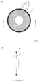
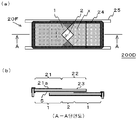
도 7 은, 본 발명의 실시예의 2 장 날개형 개구 조리개 (200A) 의 작용을 설명하는 평면도 및 단면도이다.
도 8 은, 본 발명의 실시예의 2 장 날개형 개구 조리개 (200A) 를 구성하는 조리개 날개 부재 (20A) 의 평면도이다.
도 9 는, 본 발명의 실시예의 2 장 날개형 개구 조리개를 구성하는 조리개 날개 부재 (20B) 의 평면도이다.
도 10 은, 본 발명의 실시예의 2 장 날개형 개구 조리개를 구성하는 조리개 날개 부재 (20C) 의 평면도이다.
도 11 은, 본 발명의 실시예의 2 장 날개형 개구 조리개 (200B) 의 평면도 및 단면도이다.
도 12 는, 본 발명의 실시예의 2 장 날개형 개구 조리개 (200C) 의 평면도 및 단면도이다.
도 13 은, 본 발명의 실시예의 2 장 날개형 개구 조리개 (200D) 의 평면도 및 단면도이다.
도 14 는, 본 발명의 실시예의 광원 장치 (300A) 의 개략 구성도이다.1 is a plan view and a sectional view of a
2 is a plan view and a cross-sectional view of the donut-shaped
3 is a plan view and a cross-sectional view of the donut-shaped aperture stop 100C of the embodiment of the present invention.
4 is a plan view and a cross-sectional view of the donut-shaped
5 is a cross-sectional view of the lens system equipped with the donut-
6 is a plan view of the
7 is a plan view and a sectional view for explaining the action of the two-
8 is a plan view of a
9 is a plan view of the
FIG. 10 is a plan view of a diaphragm wing member 20C constituting a two-blade aperture diaphragm according to an embodiment of the present invention.
11 is a plan view and a cross-sectional view of a two-
12 is a plan view and a sectional view of a two-
13 is a plan view and a cross-sectional view of a two-
14 is a schematic configuration diagram of a
이하, 도면을 참조하여 본 발명을 상세하게 설명한다. 또, 각 도면 중, 동일 부호는, 동일 또는 동등한 구성 요소를 나타내고 있다.Hereinafter, the present invention will be described in detail with reference to the drawings. In addition, in each figure, the same code | symbol has shown the same or equivalent component.
도 1 은, 본 발명의 제 1 조명용 개구 조리개의 일 실시예인 도넛형 개구 조리개 (100A) 의 평면도 (동 도(a)) 와, A-A 단면도 (동 도(b)) 이다. 이 도넛형 개구 조리개 (100A) 는, 고리형의 필터 영역 (1) 과 필터 영역 (1) 의 내측에 형성된 원형의 개구 영역 (2) 을 갖는 평판상 기재 (3) 와, 평판상 기재 (3) 의 외주에 끼워진 외프레임 (4) 으로 형성되어 있다. 보다 구체적으로는, 필터 영역 (1) 은, 투명한 원형의 평판상 기재 (3) 의 표면에 고리형으로 형성된 필터층 (1a) 으로 이루어지고, 평판상 기재 (3) 의 중앙부의 필터층 비형성 영역이 개구 영역 (2) 으로 되어 있다.FIG. 1: is a top view (FIG. (A)) and A-A sectional drawing (FIG. (B)) of the donut
이 개구 조리개 (100A) 는 조명 광학계용으로 구성되어 있고, 필터 영역 (1) 은, 피사체에 형광을 발광시키는 여기광의 파장역의 광을 실질적으로 감쇠하지 않고 투과하고, 또한 피사체 이미지를 형성하는 가시광역의 광을 저감 또는 차단하는 영역이다. 또, 피사체에 형광을 발광시키는 여기광의 파장역과 피사체 이미지를 형성하는 가시광의 파장역이 겹치는 경우에는, 여기광의 파장역의 광을 실질적으로 감쇠하지 않고 투과하고, 또한 피사체 이미지를 형성하는 가시광역의 광 중 여기광의 파장역 이외의 광을 저감 또는 차단하는 영역이다.This
또한, 개구 영역 (2) 은, 피사체에 형광을 발광시키는 여기광의 파장역의 광과 피사체 이미지를 형성하는 가시광역 (예를 들어, 파장 400∼800 ㎚) 의 광을 실질적으로 감쇠하지 않고 투과하는 영역이다. 이 개구 영역 (2) 은, 특정한 파장역에 대하여 필터 기능을 갖지 않는 전체 광투과 영역으로 해도 된다. 또, 본 실시예에서는 개구 영역 (2) 이 원형의 양태를 나타냈지만, 본 발명에 있어서, 개구 영역 (2) 은 여러 가지 형상을 취할 수 있고, 예를 들어 타원형이어도 되고, 사각형이어도 된다.In addition, the
여기서, 필터 영역 (1) 의 광의 투과 특성은, 관찰 대상으로 하는 피사체, 광감수성 물질, 광조영제 등의 종류나 관찰 목적 등에 따라 적절히 정할 수 있다. 예를 들어, 생체 내에 ICG 를 축적시키고, 그 축적 부위를 관찰 부위로 하고, ICG 에 여기광을 조사함으로써 형광을 발광시키고, 그 형광을 관찰하는 경우, ICG 의 여기 파장의 피크는 805 ㎚ 이고, ICG 의 형광 파장의 피크는 845 ㎚ 이므로, 750∼810 ㎚ 를 여기 파장역으로 하고, 이 여기 파장역을 포함하는 백색광을 광원으로 하는 것이 바람직하다. 따라서, 필터 영역 (1) 에서는, 750∼810 ㎚ 의 여기 파장역의 광은 투과하지만, 그것보다 단파장측의 가시광역의 광은 저감 또는 차단되도록 한다.Here, the permeation | transmission characteristic of the light of the filter area |
또, 이와 같이 도넛형 개구 조리개 (100A) 의 광의 투과 특성을 설정하면, 개구 영역 (2) 을 형광 파장역의 광이 통과하기 때문에, 이 도넛형 개구 조리개 (100A) 의 사용시에는, 810 ㎚ 보다 장파장측의 광을 차단하는 형광 파장역 컷 필터를 병용하는 것이 바람직하다. 또는, 도 2 에 나타낸 도넛형 개구 조리개 (100B) 와 같이, 평판상 기재 (3) 의 편면에 고리형으로 필터 영역 (1) 을 형성함과 함께, 평판상 기재 (3) 의 타면 전체면에 810 ㎚ 보다 장파장측의 광을 차단하는 형광 파장역 컷 필터층 (5) 을 형성해도 된다.Moreover, when the light transmission characteristic of the donut-
한편, PDD 법에 있어서 광감수성 물질로서 헤마토포르피린 유도체 (HpD) 를 사용하는 경우, 405 ㎚ 를 피크 파장으로 하는 여기광에 의해, HpD 를 축적한 종양 세포는 피크 파장 630 ㎚ 와 690 ㎚ 의 형광을 발한다. 그래서, 여기광의 파장역을 385∼425 ㎚ 로 하고, 관찰하는 형광의 파장역을 610∼720 ㎚ 로 설정하고, 광원을, 여기광의 파장역을 포함하는 백색광으로 하는 것이 바람직하다. 따라서, 필터 영역 (1) 으로는, 여기광의 파장역인 385∼425 ㎚ 의 광을 투과하지만, 이 파장역보다 단파장측의 가시광이나 장파장측의 가시광은 차단 또는 저감시키는 것이 바람직하고, 이 여기광의 파장역보다 단파장측 및 장파장측의 광을 차단하는 것이 보다 바람직하다. 또한, 전술한 ICG 에 의한 관찰 이미지를 취하는 경우에 준하여, 적절히 도넛형 개구 조리개의 사용시에는 형광 파장역 컷 필터를 사용하거나, 또는 도넛형 개구 조리개에 형광 파장역 컷 필터층을 형성하는 것이 바람직하다.On the other hand, in the case of using the hematoporphyrin derivative (HpD) as a photosensitive material in the PDD method, tumor cells accumulating HpD by excitation light having 405 nm as the peak wavelength exhibit fluorescence having a peak wavelength of 630 nm and 690 nm. Foot. Therefore, it is preferable to set the wavelength range of excitation light to 385-425 nm, set the wavelength range of fluorescence to observe to 610-720 nm, and to make a light source into white light containing the wavelength range of excitation light. Therefore, the
필터 영역 (1) 의 면적 (S1) 과 개구 영역 (2) 의 면적 (S2) 의 비율은, 피사체의 관찰 부위로부터의 형광에 의한 관찰 이미지가, 조명광에 의한 피사체 이미지 중에 묻히지 않고 명료하게 관찰할 수 있도록 하기 위해, 광원의 강도나 촬상 장치의 감도 등에 따라 적절히 정한다.The ratio of the area S1 of the
필터 영역 (1) 을 형성하는 필터층 (1a) 은, 증착법이나 스퍼터법 등의 일반적인 광학 필터용 박막 형성 방법에 따라, 상기 서술한 광의 투과 특성을 갖도록 평판상 기재 (3) 에 형성할 수 있다.The
평판상 기재 (3) 로는, 본 실시예에 있어서는, 투명한 평행 평면판을 사용하는 것이 바람직하고, 예를 들어 청판 유리, 백판 유리, 광학 유리, 아크릴 수지판 등으로 형성할 수 있다. 평판상 기재 (3) 의 두께는, 평판상 기재 (3) 의 재질, 필터 영역 (1) 의 외경 등에 따라 적절히 정할 수 있다.As the
본 발명의 개구 조리개는 여러 가지 양태를 취할 수 있다. 예를 들어, 도 3 에 나타낸 개구 조리개 (100C) 와 같이, 평판상 기재 (3) 로서, 개구 영역 (2) 이 오려내어진 고리형의 기판을 사용해도 된다. 또는, 도 4 에 나타낸 개구 조리개 (100D) 와 같이, 색재가 균일하게 분산된 평판상 기재 (3) 를 사용함으로써 필터 영역 (1) 을 형성하고, 그 평판상 기재 (3) 자체를 노치함으로써 개구 영역 (2) 을 형성해도 된다.The aperture stop of the present invention can take various aspects. For example, as the flat diaphragm 100C shown in FIG. 3, you may use the annular board | substrate with which the opening area |
또한, 필터 영역 (1) 을 형성하는 필터층 (1a) 은, 평판상 기재 (3) 에 형성하는 것에 한정되지 않는다. 필터층 (1a) 을 형성하는 기재를 렌즈로 하고, 그 표면에 형성해도 된다. 도 5 의 개구 조리개 (100E) 는, 광원 (60) 이 발한 광을 내시경용의 라이트 가이드 화이버 (70) 에 집광하는 콘덴서 렌즈 (3b) 의 표면에, 링상으로 필터층 (1a) 을 형성한 것이다.In addition, the
이와 같이 렌즈면에 필터층 (1a) 을 형성함으로써, 독립된 광학 부재로서 기재에 필터층을 형성한 개구 조리개에 비해, 개구 조리개가 차지하는 스페이스를 생략할 수 있다. 또, 필터층 (1a) 을 형성하는 렌즈 (3b) 로는, 종래의 광원 장치 내의 렌즈계에서 개구 조리개가 설치되어 있는 위치 근방의 렌즈로 하는 것이 바람직하다.By forming the
도 6 은, 상기 서술한 도넛형 개구 조리개 (100A) 와 동일한 개구 조리개로서, 필터 영역 (1) 과 개구 영역 (2) 의 면적비가 상이한 것을, 원반형 기판 (6) 의 회전 중심 (6o) 의 둘레에 복수 배치한 회전형 개구 조리개 (150) 의 평면도이다. 이 회전형 개구 조리개 (150) 에 의하면, 원반형 기판 (6) 을 화살표와 같이 회전시킴으로써, 필터 영역 (1) 과 개구 영역 (2) 이 원하는 비를 갖는 도넛형 개구 조리개 (100A) 를 용이하게 선택하고, 피사체를 조명할 수 있다.FIG. 6: is the same aperture stop as 100 A of donut type aperture stops mentioned above, Comprising: The area ratio of the filter area |
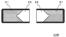
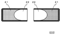
도 7 은, 본 발명의 제 2 개구 조리개의 일 실시예인 2 장 날개형 개구 조리개 (200A) 의 설명도이고, 도 8 은, 이 2 장 날개형 개구 조리개 (200A) 를 구성하는 한 쌍의 조리개 날개 부재 (20A) 의 평면도이다.FIG. 7: is explanatory drawing of 200 A of two-blade aperture diaphragm which is an example of the 2nd aperture diaphragm of this invention, and FIG. 8 is a pair of diaphragm which comprises this two-
조리개 날개 부재 (20A) 는, 사각형의 평판상 기재 (23) 표면의 좌우 편측에 필터층 (21a) 이 형성된 필터부 (21) 와 필터층 (21a) 의 비형성 영역인 비필터부 (22) 를 갖고, 외프레임 (24) 에 끼워져 있다. 여기서, 필터층 (21a) 은 비필터부 (22) 측이 V 자형으로 패인 형상을 하고 있다. 이 필터층 (21a) 은, 전술한 도넛형 개구 조리개 (100A) 의 필터층 (1a) 과 동일하게, 피사체에 형광을 발광시키는 여기광의 파장역의 광을 실질적으로 감쇠하지 않고 투과하고, 또한 피사체 이미지를 형성하는 가시광역의 광을 저감 또는 차단하는 광의 투과 특성을 갖는 것이고, 전술한 도넛형 개구 조리개 (100A) 의 필터층 (1a) 과 동일하게 박막의 증착 등에 의해 형성된다. 또한, 사각형의 평판상 기재 (23) 는, 전술한 개구 조리개 (100A) 와 동일하게 투명한 유리판, 아크릴 수지판 등으로 형성된다.20 A of diaphragm wing members have the
도 7 에 나타낸 2 장 날개형 개구 조리개 (200A) 는, 한 쌍의 조리개 날개 부재 (20A) 를, 쌍방의 비필터부 (21) 가 서로 겹치도록 조합하고, 레일 (25) 상에 이동 가능하게 장착한 것이다. 이 2 장 날개형 개구 조리개 (200A) 에 의하면, 한 쌍의 조리개 날개 부재 (20A) 의 비필터부 (22) 의 서로 겹친 영역이, 2 장 날개형 개구 조리개 (200A) 의 개구 영역 (2) 이 되고, 피사체에 형광을 발광시키는 여기광의 파장역의 광과 피사체 이미지를 형성하는 가시광역의 광을 투과시킨다. 또한, 이 개구 영역 (2) 을 둘러싸는 한 쌍의 필터부 (21) 가, 2 장 날개형 개구 조리개 (200A) 의 필터 영역 (1) 이 되고, 피사체에 형광을 발광시키는 여기광의 파장역의 광의 투과를 투과시키고, 또한 피사체 이미지를 형성하는 가시광의 광을 저감 또는 차단한다.200 A of two-winged aperture stops shown in FIG. 7
따라서, 이 2 장 날개형 개구 조리개 (200A) 에 의하면, 개구 영역 (2) 의 면적이 가변이 되고, 예를 들어 도 7(a) 에 나타내는 바와 같이, 개구 영역 (2) 을 최대로 한 상태와, 동 도(b) 에 나타내는 바와 같이 개구 영역 (2) 을 좁힌 상태와, 동 도(c) 에 나타내는 바와 같이 개구 영역 (2) 을 더욱 좁힌 상태로, 개구 영역 (2) 의 면적을 연속적으로 변화시킬 수 있다. 따라서, 피사체 이미지를 형성하는 광과 형광 이미지를 형성하는 여기광의 광량의 밸런스의 조정을 보다 적절히 실시할 수 있다. 또, 도 7 에 있어서, 개구 영역 (2) 둘레의 파선 원형 (X) 은, 이 2 장 날개형 개구 조리개 (200A) 를 광원 장치 등의 광학계에 장착한 경우의 장착 위치에서의 광원으로부터의 광로 직경을 나타내고 있다. 이와 같이 개구 영역 (2) 의 개폐의 유무에 관계 없이, 필터 영역 (1) 의 직경을, 2 장 날개형 개구 조리개 (200A) 의 장착 위치에서의 광원으로부터의 광로 직경보다 크게 하고, 필터 영역 (1) 이 광원으로부터의 광로를 차단하지 않도록 하는 것이 바람직하다. 이것에 의해, 광원에 포함되는 여기광 성분의 로스를 저감시킬 수 있다.Therefore, according to this two-
또, 2 장 날개형 개구 조리개 (200A) 에 있어서, 한 쌍의 조리개 날개 부재 (20A) 를 쌍방의 비필터부 (22) 가 서로 겹치도록 조합하는 데에 있어서, 한 쌍의 조리개 날개 부재 (20A) 는, 이들의 대향면이 서로 접촉하지 않는 한, 가능한 한 근접하여 배치하는 것이 바람직하다.Moreover, in 200 A of two wing type aperture diaphragms, when combining a pair of
조리개 날개 부재 (20A) 의 구동 기구로는, 개구 영역 (2) 의 중심 (p) 을 중심으로 하여 좌우 대칭으로 한 쌍의 조리개 날개 부재 (20A) 가 움직이도록, 한 쌍의 조리개 날개 부재 (20A) 를 공지된 접속구로 접속하는 것이 바람직하다. 또한, 조리개 날개 부재 (20A) 의 구동원으로는, 수동이어도 되고, 스테핑 모터 등을 사용해도 된다.As the drive mechanism of the
본 발명의 개구 조리개는, 추가로 여러 가지 양태를 취할 수 있다. 예를 들어, 도 8 에 나타낸 조리개 날개 부재 (20A) 에 있어서, 필터부 (21) 의 V 자형의 개구 각도 (θ) 나 V 자형의 깊이 (d) 는, 한 쌍의 비필터부 (22) 의 겹침에 의해 개구 영역 (2) 이 형성되는 한 특별히 제한은 없다.The aperture stop of the present invention may further take various aspects. For example, in the
도 8 에 나타낸 조리개 날개 부재 (20A) 에서는, 필터부 (21) 는, 그 비필터부 (22) 측이 V 자형으로 패여 있는데, 한 쌍의 비필터부 (22) 의 겹침에 의해 개구 영역 (2) 을 형성할 수 있는 한 패임 형상 자체에는 특별히 제한 없고, 도 9 에 나타내는 조리개 날개 부재 (20B) 와 같이 V 자형의 패임의 선단부를 반원형으로 패이게 함으로써, 개구 영역 (2) 의 면적을 가장 좁힌 상태에서, 개구 영역 (2) 이 원형이 되도록 해도 된다. 또, 도 10 에 나타내는 조리개 날개 부재 (20C) 와 같이, 필터부 (21) 의 비필터부 (22) 측을 반타원상 등으로 패이게 해도 된다.In 20 A of diaphragm wing members shown in FIG. 8, although the
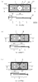
도 11 에 나타내는 2 장 날개형 개구 조리개 (200B) 와 같이, 조리개 날개 부재 (20D) 를 형성하는 평판상 기재 (23) 의 평면 형상 자체를, 필터부 (21) 와 동일하게 패임을 갖는 형상으로 해도 되고, 또는 도 12 에 나타내는 2 장 날개형 개구 조리개 (200C) 와 같이, 색재가 균일하게 분산되어 있음으로써 평판상 기재 (23) 자체가 필터층 (21a) 과 동일한 광투과 특성을 갖는 것을 사용하고, 그것을 패임을 갖는 형상으로 노치함으로써 개구 영역 (2) 을 형성해도 된다.Like the two-
또, 본 발명의 전술한 2 장 날개형 개구 조리개에 있어서는, 전술한 도넛형 개구 조리개와 동일하게, 도 13 에 나타내는 바와 같이, 필요에 따라, 필터층 (21a) 과 반대측의 평판상 기판 (23) 에 형광 파장역 컷 필터층 (5) 을 형성해도 된다.In addition, in the above-mentioned two-winged aperture stop of the present invention, as shown in FIG. 13, the
본 발명의 개구 조리개는, 추가로 여러 가지 양태를 취할 수 있다. 예를 들어, 필터부와 비필터부를 갖는 조리개 날개 부재를 3 장 이상 조합함으로써, 필터 영역과, 그 필터 영역의 내측에 위치하는 개구 영역이 형성되도록 해도 된다. 단, 필터부의 겹침이 많으면, 광원으로부터의 열로 필터부가 열팽창하여 필터부의 겹침 부분에 변형이 생김으로써 조명 불균일이 발생하는 경우가 있는데, 이러한 조명 불균일이 발생하기 어려운 점에서, 3 장 이상의 조리개 날개 부재를 갖는 개구 조리개보다 2 장 날개형 개구 조리개가 바람직하다.The aperture stop of the present invention may further take various aspects. For example, by combining three or more of the diaphragm wing members which have a filter part and a non-filter part, you may make it form the filter area | region and the opening area located inside this filter area | region. However, when there are many overlaps of filter parts, illumination nonuniformity may arise by heat expansion of a filter part by the heat from a light source, and a deformation | transformation may arise in the overlapping part of a filter part. Two winged aperture diaphragms are preferable to the aperture diaphragm having a diaphragm.
본 발명의 개구 조리개는, 조명광에 의한 피사체 이미지와, 피사체의 관찰 부위로부터의 형광 이미지를 동시에 촬상하는 여러 가지 촬상 장치의 광원 장치에 널리 사용할 수 있고, 그것에 의해, 피사체 이미지에 대하여 형광 이미지가 미약해지는 것을 방지할 수 있다.The aperture stop of the present invention can be widely used in light source devices of various imaging apparatuses that simultaneously image a subject image by illumination light and a fluorescent image from an observation portion of a subject, whereby the fluorescent image is weak with respect to the subject image. Can be prevented.
도 14 는, ICG 를 이용한 공지된 근적외 형광 화상 촬상 내시경 장치의 광원 장치 (300A) 에 본 발명의 2 장 날개형 개구 조리개 (200A) 를 장착한 것의 개략 구성도이다. 이 광원 장치 (300A) 를 장착하는 내시경 장치는, 생체를 피사체로 하여 가시광에 의한 피사체 이미지를 찍음과 함께, 생체 조직에 투여한 ICG 가 발하는 적외광 대역의 형광 화상도 동시에 찍는 것이고, 특허문헌 4 에 기재된 내시경 장치나, PCT/JP2009/67352 에 기재된 내시경 장치와 동일한 구성으로 할 수 있다. 바람직하게는 PCT/JP2009/67352 에 기재된 내시경 장치와 같이, 피사체의 관찰 부위로부터의 형광에 대응하는 파장역의 광을 투과하고, 또한 피사체 이미지를 형성하는 가시광역의 투과를 저감 또는 차단하는 개구 조리개를 CCD 등의 촬상 소자의 전면 (前面) 에 구비한 내시경 장치를 사용한다. 이것에 의해, 간단한 구성으로 피사체 이미지에 대한 형광 이미지의 강도의 비율을 보다 더 개선할 수 있다.Fig. 14 is a schematic configuration diagram of the two-
광원 장치 (300A) 는, 할로겐 램프, 크세논 램프, LED 등의 백색 광원 (60), 그 배후에 형성된 오목면경 (61), 백색 광원 (60) 의 전면에 순차 형성된 형광 파장역 컷 필터 (62), 도 7 에 나타낸 2 장 날개형 개구 조리개 (200A), 및 콘덴서 렌즈 (3b) 를 갖는다. 또한, 2 장 날개형 개구 조리개 (200A) 와 콘덴서 렌즈 (3b) 사이에는, 필요에 따라, 조명광의 전체 광량을 좁히는 전체 광량 조리개 (63) 를 형성할 수 있다.The
이 광원 장치 (300A) 에 의하면, 2 장 날개형 개구 조리개 (200A) 의 필터 영역 (1) 과 개구 영역 (2) 의 비의 조정에 의해, 여기광의 광량과 가시광역의 광량이 적절한 비율의 조명광을 내시경 장치의 라이트 가이드 화이버 (70) 에 보낼 수 있다.According to this
또, 이러한 광원 장치 (300A) 에 있어서, 도 7 에 나타낸 2 장 날개형 개구 조리개 (200A) 대신에, 전술한 다른 2 장 날개형 개구 조리개 (200B∼200D), 도넛형 개구 조리개 (100A∼100E), 또는 회전형 개구 조리개 (150) 등을 형성해도 된다.In addition, in such a
산업상 이용가능성Industrial availability
본 발명의 개구 조리개는, ICG 등의 형광 시약을 이용한 형광 화상 촬상 장치, PDD, PDT 등의 의료 분야의 촬상 장치의 광원 장치에서 유용하고, 또한 식품, 각종 재료의 분석 시험에 있어서 형광 화상을 찍는 경우의 광원 장치 등에 있어서도 유용하다.The aperture stop of the present invention is useful in a light source device of a fluorescence image pickup device using a fluorescent reagent such as ICG, an image pickup device in a medical field such as PDD, PDT, and also takes a fluorescence image in an analysis test of food and various materials. It is also useful in the case of a light source device in the case.
1 : 필터 영역
1a : 필터층
2 : 개구 영역
3 : 평판상 기재
3b : 콘덴서 렌즈
4 : 외프레임
5 : 형광 파장역 컷 필터층
6 : 원반형 기판
20A, 20B, 20C, 20D, 20E, 20F : 조리개 날개 부재
21 : 필터부
21a : 필터층
22 : 비필터부
23 : 평판상 기재
24 : 외프레임
25 : 레일
50 : 여기광 컷 필터
60 : 광원
61 : 오목면경
62 : 형광 파장역 컷 필터
63 : 전체 광량 조리개
70 : 라이트 가이드 화이버
100A, 100B, 100C, 100D, 100E : 도넛형 개구 조리개
150 : 회전형 개구 조리개
200A, 200B, 200C, 200D : 2 장 날개형 개구 조리개
300A : 광원 장치1: filter area
1a: filter layer
2: opening area
3: flat plate material
3b: condenser lens
4: outer frame
5: fluorescent wavelength range cut filter layer
6: disc shaped substrate
Aperture wing member: 20A, 20B, 20C, 20D, 20E, 20F
21: filter unit
21a: filter layer
22: non-filter unit
23: flat plate substrate
24: outer frame
25: Rail
50: excitation light cut filter
60: Light source
61: concave mirror
62: fluorescence wavelength range cut filter
63: total light aperture
70: Light Guide Fiber
100A, 100B, 100C, 100D, 100E: donut aperture aperture
150: rotary aperture stop
Two-winged aperture aperture: 200A, 200B, 200C, 200D
300A: light source device
Claims (9)
기재에 고리형으로 필터 영역이 형성되고, 상기 필터 영역의 내측에 개구 영역이 형성되고, 필터 영역이, 피사체에 형광을 발광시키는 여기광의 파장역의 광을 투과시키고, 또한 피사체 이미지를 형성하는 가시광역의 광의 투과를 저감 또는 차단하는, 조명용 개구 조리개.As an aperture stop for illumination used for a light source device in the case of observing the subject image by reflection of the illumination light of visible range and the fluorescent image by the fluorescent substance in a subject simultaneously,
A filter region is formed in the substrate in an annular shape, an opening region is formed inside the filter region, and the filter region transmits light in the wavelength range of the excitation light that emits fluorescence to the subject, and forms a subject image. An aperture stop for illumination that reduces or blocks the transmission of light in a wide area.
여기광이 적외광인, 조명용 개구 조리개.The method of claim 1,
Aperture aperture for illumination, wherein excitation light is infrared light.
개구 조리개의 전체면에, 상기 형광의 파장역의 광의 투과를 차단하는 필터층이 형성되어 있는, 조명용 개구 조리개.3. The method according to claim 1 or 2,
The aperture stop for illumination in which the filter layer which interrupts the transmission of the light of the said fluorescence wavelength range is formed in the whole surface of an aperture stop.
일부 또는 전부에 필터부가 형성된 조리개 날개 부재를 복수 구비하고, 복수의 조리개 날개 부재의 필터부로 형성된 필터 영역과 상기 필터 영역의 내측에 위치하는 개구 영역을 갖고, 필터 영역이, 피사체에 형광을 발광시키는 여기광의 파장역의 광을 투과시키고, 또한 피사체 이미지를 형성하는 가시광역의 광의 투과를 저감 또는 차단하는, 조명용 개구 조리개.As an aperture stop for illumination used for a light source device in the case of observing the subject image by reflection of the illumination light of visible range and the fluorescent image by the fluorescent substance in a subject simultaneously,
Some or all of the aperture wing members provided with the filter part are provided in multiple numbers, The filter area | region formed with the filter part of a some aperture wing member, and the opening area located inside the said filter area | region, The filter area | region makes a fluorescence light-emitting to a subject. The aperture stop for illumination which permeate | transmits the light of the wavelength range of an excitation light, and reduces or interrupts the transmission of the light of the visible range which forms an object image.
개구 영역의 면적이 가변인, 조명용 개구 조리개.5. The method of claim 4,
An aperture stop for illumination, wherein the area of the aperture area is variable.
여기광이 적외광인, 조명용 개구 조리개.The method according to claim 4 or 5,
Aperture aperture for illumination, wherein excitation light is infrared light.
필터 영역의 직경이, 조명용 개구 조리개의 장착 위치에 있어서의 광원으로부터의 광로 직경보다 크고, 필터 영역이 상기 광로를 차단하지 않는, 조명용 개구 조리개.7. The method according to any one of claims 4 to 6,
The illumination aperture diaphragm in which the diameter of a filter area | region is larger than the optical path diameter from the light source in the mounting position of an illumination aperture stop, and a filter area does not block the said optical path.
백색 광원과, 제 1 항 내지 제 7 항 중 어느 한 항에 기재된 조명용 개구 조리개를 구비한, 광원 장치.A light source device for use in an imaging device that simultaneously observes a subject image by illumination light and a fluorescence image from an observation site of a subject,
The light source device provided with the white light source and the aperture stop for illumination of any one of Claims 1-7.
내시경 장치에 사용되는, 광원 장치.The method of claim 8,
The light source device used for an endoscope device.
Applications Claiming Priority (3)
| Application Number | Priority Date | Filing Date | Title |
|---|---|---|---|
| JP2011010056 | 2011-01-20 | ||
| JPJP-P-2011-010056 | 2011-01-20 | ||
| PCT/JP2011/079901 WO2012098806A1 (en) | 2011-01-20 | 2011-12-22 | Lighting diaphragm |
Publications (1)
| Publication Number | Publication Date |
|---|---|
| KR20140001985A true KR20140001985A (en) | 2014-01-07 |
Family
ID=46515443
Family Applications (1)
| Application Number | Title | Priority Date | Filing Date |
|---|---|---|---|
| KR1020137019247A KR20140001985A (en) | 2011-01-20 | 2011-12-22 | Lighting diaphragm |
Country Status (6)
| Country | Link |
|---|---|
| US (1) | US9175831B2 (en) |
| EP (1) | EP2666402B1 (en) |
| JP (1) | JP5796244B2 (en) |
| KR (1) | KR20140001985A (en) |
| CN (1) | CN103327885B (en) |
| WO (1) | WO2012098806A1 (en) |
Families Citing this family (21)
| Publication number | Priority date | Publication date | Assignee | Title |
|---|---|---|---|---|
| US9843740B2 (en) | 2013-02-13 | 2017-12-12 | Panasonic Intellectual Property Management Co., Ltd. | Multispectral imaging device and multispectral imaging method |
| US10948638B2 (en) | 2014-03-04 | 2021-03-16 | Stryker European Operations Limited | Spatial and spectral filtering apertures and optical imaging systems including the same |
| WO2015137148A1 (en) * | 2014-03-14 | 2015-09-17 | ソニー株式会社 | Image capturing device, iris device, image capturing method, and program |
| JP6727800B2 (en) | 2015-03-05 | 2020-07-22 | キヤノン株式会社 | Light quantity adjusting device, lens barrel, and optical device |
| WO2017035646A1 (en) | 2015-08-31 | 2017-03-09 | Novadaq Technologies Inc. | Polarization dependent filter, system using the same, and associated kits and methods |
| WO2017047239A1 (en) * | 2015-09-16 | 2017-03-23 | 富士フイルム株式会社 | Focus apparatus, imaging system, and focus driving signal outputting method |
| CN106773018B (en) * | 2015-11-23 | 2019-05-28 | 中国科学院大连化学物理研究所 | A kind of infrared aperture-variable diaphragm |
| CN105425505B (en) * | 2015-12-10 | 2017-10-31 | 上海机电工程研究所 | The iris diaphgram adjusting method of off-axis refractive and reflective optical system |
| CN105678215A (en) * | 2015-12-28 | 2016-06-15 | 北京天诚盛业科技有限公司 | Imaging module, imaging device and mobile terminal |
| JP6671030B2 (en) * | 2016-03-09 | 2020-03-25 | パナソニックIpマネジメント株式会社 | Lighting equipment |
| EP3251578A1 (en) | 2016-05-30 | 2017-12-06 | Leica Instruments (Singapore) Pte. Ltd. | Medical device for the observation of a partly fluorescent object, using a filter system with a transmission window |
| EP3285116B1 (en) | 2016-08-17 | 2020-07-08 | Leica Instruments (Singapore) Pte. Ltd. | Multispectral iris device |
| US10386627B2 (en) * | 2017-01-20 | 2019-08-20 | Verily Life Sciences Llc | Simultaneous visible and fluorescence endoscopic imaging |
| EP3440989A1 (en) * | 2017-08-09 | 2019-02-13 | Koninklijke Philips N.V. | System for imaging an eye |
| JP6580646B2 (en) * | 2017-09-04 | 2019-09-25 | 池上通信機株式会社 | Imaging device |
| CN109549614B (en) * | 2017-09-27 | 2022-09-20 | 深圳市绎立锐光科技开发有限公司 | Endoscope system |
| CN109348015B (en) * | 2018-11-27 | 2020-09-25 | 维沃移动通信(杭州)有限公司 | Camera module, control method of camera module and mobile terminal |
| CN109520987A (en) * | 2018-12-19 | 2019-03-26 | 苏州汶颢微流控技术股份有限公司 | ATP fluorescence detector |
| TWI745745B (en) * | 2019-09-10 | 2021-11-11 | 光芒光學股份有限公司 | Imaging lens and a manufacturing method of a light- shielding element |
| WO2021059044A1 (en) * | 2019-09-24 | 2021-04-01 | Agilent Technologies, Inc. | Variable transmission aperture |
| US11853845B2 (en) * | 2020-09-02 | 2023-12-26 | Cognex Corporation | Machine vision system and method with multi-aperture optics assembly |
Family Cites Families (16)
| Publication number | Priority date | Publication date | Assignee | Title |
|---|---|---|---|---|
| US6293911B1 (en) * | 1996-11-20 | 2001-09-25 | Olympus Optical Co., Ltd. | Fluorescent endoscope system enabling simultaneous normal light observation and fluorescence observation in infrared spectrum |
| JP3962122B2 (en) | 1996-11-20 | 2007-08-22 | オリンパス株式会社 | Endoscope device |
| US7179222B2 (en) | 1996-11-20 | 2007-02-20 | Olympus Corporation | Fluorescent endoscope system enabling simultaneous achievement of normal light observation based on reflected light and fluorescence observation based on light with wavelengths in infrared spectrum |
| JP3713347B2 (en) | 1996-11-25 | 2005-11-09 | オリンパス株式会社 | Fluorescence endoscope device |
| JP2001078205A (en) | 1999-09-01 | 2001-03-23 | Hamamatsu Photonics Kk | Very weak light color image pickup device |
| JP4010779B2 (en) * | 2001-06-08 | 2007-11-21 | ペンタックス株式会社 | Image detection device and diaphragm device |
| JP4931288B2 (en) * | 2001-06-08 | 2012-05-16 | ペンタックスリコーイメージング株式会社 | Image detection device and diaphragm device |
| JP3802870B2 (en) | 2002-12-20 | 2006-07-26 | 株式会社タムロン | Light control device |
| JP4164355B2 (en) * | 2002-12-26 | 2008-10-15 | キヤノン株式会社 | Light amount adjusting device and optical apparatus using the same |
| US7042662B2 (en) | 2002-12-26 | 2006-05-09 | Canon Kabushiki Kaisha | Light amount adjusting device, and optical device using the light amount adjusting device |
| JP4438056B2 (en) * | 2003-06-26 | 2010-03-24 | キヤノン株式会社 | Manufacturing method of light quantity adjusting member |
| JP4744288B2 (en) | 2005-12-21 | 2011-08-10 | オリンパスメディカルシステムズ株式会社 | Endoscope device |
| JP4971816B2 (en) * | 2007-02-05 | 2012-07-11 | 三洋電機株式会社 | Imaging device |
| JP2008259591A (en) | 2007-04-10 | 2008-10-30 | Hamamatsu Photonics Kk | Light source device for fluorescence observation and fluorescence observation instrument using the same |
| JP2009067352A (en) | 2007-09-18 | 2009-04-02 | Nippon Seiki Co Ltd | Head-up display device |
| JPWO2011007435A1 (en) * | 2009-07-16 | 2012-12-20 | 株式会社山野光学 | Aperture stop |
-
2011
- 2011-12-22 JP JP2012553585A patent/JP5796244B2/en active Active
- 2011-12-22 CN CN201180065496.5A patent/CN103327885B/en active Active
- 2011-12-22 US US13/980,625 patent/US9175831B2/en active Active
- 2011-12-22 WO PCT/JP2011/079901 patent/WO2012098806A1/en active Application Filing
- 2011-12-22 KR KR1020137019247A patent/KR20140001985A/en not_active Application Discontinuation
- 2011-12-22 EP EP11856442.6A patent/EP2666402B1/en active Active
Also Published As
| Publication number | Publication date |
|---|---|
| JP5796244B2 (en) | 2015-10-21 |
| US20130306880A1 (en) | 2013-11-21 |
| EP2666402B1 (en) | 2020-04-15 |
| EP2666402A4 (en) | 2015-11-25 |
| WO2012098806A1 (en) | 2012-07-26 |
| EP2666402A1 (en) | 2013-11-27 |
| JPWO2012098806A1 (en) | 2014-06-09 |
| US9175831B2 (en) | 2015-11-03 |
| CN103327885A (en) | 2013-09-25 |
| CN103327885B (en) | 2017-08-29 |
Similar Documents
| Publication | Publication Date | Title |
|---|---|---|
| KR20140001985A (en) | Lighting diaphragm | |
| EP2454985B1 (en) | Aperture stop | |
| JP4842325B2 (en) | Light source device for fluorescence diagnosis and photodynamic therapy | |
| US7328060B2 (en) | Cancer detection and adaptive dose optimization treatment system | |
| ES2531757T3 (en) | Microscope system | |
| CN102469932A (en) | Light source device and endoscope system | |
| JP5930454B2 (en) | Light source device | |
| JP2003260025A5 (en) | ||
| Leonhard | New incoherent autofluorescence/fluorescence system for early detection of lung cancer | |
| CA2443927A1 (en) | Method for viewing tumor tissue located within a body cavity | |
| JP2016120104A (en) | Lighting device, lighting method, and observation device | |
| JP5418707B2 (en) | Aperture stop | |
| JP5224078B2 (en) | Aperture stop | |
| KR102368406B1 (en) | light source device | |
| CN103837509A (en) | Time difference type light source apparatus for fluorescence detection, image capture system and capture method | |
| JP2017099719A (en) | Slit-lamp microscope |
Legal Events
| Date | Code | Title | Description |
|---|---|---|---|
| WITN | Application deemed withdrawn, e.g. because no request for examination was filed or no examination fee was paid |