KR20140001200A - Dual air flow exchanger with enhanced heat and humidity transfers - Google Patents
Dual air flow exchanger with enhanced heat and humidity transfers Download PDFInfo
- Publication number
- KR20140001200A KR20140001200A KR1020137007603A KR20137007603A KR20140001200A KR 20140001200 A KR20140001200 A KR 20140001200A KR 1020137007603 A KR1020137007603 A KR 1020137007603A KR 20137007603 A KR20137007603 A KR 20137007603A KR 20140001200 A KR20140001200 A KR 20140001200A
- Authority
- KR
- South Korea
- Prior art keywords
- exchanger
- air
- cell
- honeycomb structure
- airflow
- Prior art date
Links
Images


Classifications
-
- F—MECHANICAL ENGINEERING; LIGHTING; HEATING; WEAPONS; BLASTING
- F28—HEAT EXCHANGE IN GENERAL
- F28F—DETAILS OF HEAT-EXCHANGE AND HEAT-TRANSFER APPARATUS, OF GENERAL APPLICATION
- F28F1/00—Tubular elements; Assemblies of tubular elements
- F28F1/02—Tubular elements of cross-section which is non-circular
- F28F1/022—Tubular elements of cross-section which is non-circular with multiple channels
-
- F—MECHANICAL ENGINEERING; LIGHTING; HEATING; WEAPONS; BLASTING
- F28—HEAT EXCHANGE IN GENERAL
- F28D—HEAT-EXCHANGE APPARATUS, NOT PROVIDED FOR IN ANOTHER SUBCLASS, IN WHICH THE HEAT-EXCHANGE MEDIA DO NOT COME INTO DIRECT CONTACT
- F28D21/00—Heat-exchange apparatus not covered by any of the groups F28D1/00 - F28D20/00
-
- F—MECHANICAL ENGINEERING; LIGHTING; HEATING; WEAPONS; BLASTING
- F24—HEATING; RANGES; VENTILATING
- F24F—AIR-CONDITIONING; AIR-HUMIDIFICATION; VENTILATION; USE OF AIR CURRENTS FOR SCREENING
- F24F3/00—Air-conditioning systems in which conditioned primary air is supplied from one or more central stations to distributing units in the rooms or spaces where it may receive secondary treatment; Apparatus specially designed for such systems
- F24F3/12—Air-conditioning systems in which conditioned primary air is supplied from one or more central stations to distributing units in the rooms or spaces where it may receive secondary treatment; Apparatus specially designed for such systems characterised by the treatment of the air otherwise than by heating and cooling
- F24F3/14—Air-conditioning systems in which conditioned primary air is supplied from one or more central stations to distributing units in the rooms or spaces where it may receive secondary treatment; Apparatus specially designed for such systems characterised by the treatment of the air otherwise than by heating and cooling by humidification; by dehumidification
- F24F3/147—Air-conditioning systems in which conditioned primary air is supplied from one or more central stations to distributing units in the rooms or spaces where it may receive secondary treatment; Apparatus specially designed for such systems characterised by the treatment of the air otherwise than by heating and cooling by humidification; by dehumidification with both heat and humidity transfer between supplied and exhausted air
-
- F—MECHANICAL ENGINEERING; LIGHTING; HEATING; WEAPONS; BLASTING
- F24—HEATING; RANGES; VENTILATING
- F24F—AIR-CONDITIONING; AIR-HUMIDIFICATION; VENTILATION; USE OF AIR CURRENTS FOR SCREENING
- F24F12/00—Use of energy recovery systems in air conditioning, ventilation or screening
- F24F12/001—Use of energy recovery systems in air conditioning, ventilation or screening with heat-exchange between supplied and exhausted air
- F24F12/006—Use of energy recovery systems in air conditioning, ventilation or screening with heat-exchange between supplied and exhausted air using an air-to-air heat exchanger
-
- F—MECHANICAL ENGINEERING; LIGHTING; HEATING; WEAPONS; BLASTING
- F28—HEAT EXCHANGE IN GENERAL
- F28D—HEAT-EXCHANGE APPARATUS, NOT PROVIDED FOR IN ANOTHER SUBCLASS, IN WHICH THE HEAT-EXCHANGE MEDIA DO NOT COME INTO DIRECT CONTACT
- F28D21/00—Heat-exchange apparatus not covered by any of the groups F28D1/00 - F28D20/00
- F28D21/0001—Recuperative heat exchangers
- F28D21/0014—Recuperative heat exchangers the heat being recuperated from waste air or from vapors
-
- F—MECHANICAL ENGINEERING; LIGHTING; HEATING; WEAPONS; BLASTING
- F28—HEAT EXCHANGE IN GENERAL
- F28D—HEAT-EXCHANGE APPARATUS, NOT PROVIDED FOR IN ANOTHER SUBCLASS, IN WHICH THE HEAT-EXCHANGE MEDIA DO NOT COME INTO DIRECT CONTACT
- F28D21/00—Heat-exchange apparatus not covered by any of the groups F28D1/00 - F28D20/00
- F28D21/0015—Heat and mass exchangers, e.g. with permeable walls
-
- F—MECHANICAL ENGINEERING; LIGHTING; HEATING; WEAPONS; BLASTING
- F28—HEAT EXCHANGE IN GENERAL
- F28D—HEAT-EXCHANGE APPARATUS, NOT PROVIDED FOR IN ANOTHER SUBCLASS, IN WHICH THE HEAT-EXCHANGE MEDIA DO NOT COME INTO DIRECT CONTACT
- F28D9/00—Heat-exchange apparatus having stationary plate-like or laminated conduit assemblies for both heat-exchange media, the media being in contact with different sides of a conduit wall
- F28D9/0062—Heat-exchange apparatus having stationary plate-like or laminated conduit assemblies for both heat-exchange media, the media being in contact with different sides of a conduit wall the conduits for one heat-exchange medium being formed by spaced plates with inserted elements
-
- F—MECHANICAL ENGINEERING; LIGHTING; HEATING; WEAPONS; BLASTING
- F28—HEAT EXCHANGE IN GENERAL
- F28F—DETAILS OF HEAT-EXCHANGE AND HEAT-TRANSFER APPARATUS, OF GENERAL APPLICATION
- F28F21/00—Constructions of heat-exchange apparatus characterised by the selection of particular materials
- F28F21/06—Constructions of heat-exchange apparatus characterised by the selection of particular materials of plastics material
- F28F21/065—Constructions of heat-exchange apparatus characterised by the selection of particular materials of plastics material the heat-exchange apparatus employing plate-like or laminated conduits
-
- F—MECHANICAL ENGINEERING; LIGHTING; HEATING; WEAPONS; BLASTING
- F24—HEATING; RANGES; VENTILATING
- F24F—AIR-CONDITIONING; AIR-HUMIDIFICATION; VENTILATION; USE OF AIR CURRENTS FOR SCREENING
- F24F3/00—Air-conditioning systems in which conditioned primary air is supplied from one or more central stations to distributing units in the rooms or spaces where it may receive secondary treatment; Apparatus specially designed for such systems
- F24F3/12—Air-conditioning systems in which conditioned primary air is supplied from one or more central stations to distributing units in the rooms or spaces where it may receive secondary treatment; Apparatus specially designed for such systems characterised by the treatment of the air otherwise than by heating and cooling
- F24F3/14—Air-conditioning systems in which conditioned primary air is supplied from one or more central stations to distributing units in the rooms or spaces where it may receive secondary treatment; Apparatus specially designed for such systems characterised by the treatment of the air otherwise than by heating and cooling by humidification; by dehumidification
- F24F2003/1435—Air-conditioning systems in which conditioned primary air is supplied from one or more central stations to distributing units in the rooms or spaces where it may receive secondary treatment; Apparatus specially designed for such systems characterised by the treatment of the air otherwise than by heating and cooling by humidification; by dehumidification comprising semi-permeable membrane
-
- Y—GENERAL TAGGING OF NEW TECHNOLOGICAL DEVELOPMENTS; GENERAL TAGGING OF CROSS-SECTIONAL TECHNOLOGIES SPANNING OVER SEVERAL SECTIONS OF THE IPC; TECHNICAL SUBJECTS COVERED BY FORMER USPC CROSS-REFERENCE ART COLLECTIONS [XRACs] AND DIGESTS
- Y02—TECHNOLOGIES OR APPLICATIONS FOR MITIGATION OR ADAPTATION AGAINST CLIMATE CHANGE
- Y02B—CLIMATE CHANGE MITIGATION TECHNOLOGIES RELATED TO BUILDINGS, e.g. HOUSING, HOUSE APPLIANCES OR RELATED END-USER APPLICATIONS
- Y02B30/00—Energy efficient heating, ventilation or air conditioning [HVAC]
- Y02B30/56—Heat recovery units
Landscapes
- Engineering & Computer Science (AREA)
- Mechanical Engineering (AREA)
- General Engineering & Computer Science (AREA)
- Physics & Mathematics (AREA)
- Thermal Sciences (AREA)
- Chemical & Material Sciences (AREA)
- Combustion & Propulsion (AREA)
- Geometry (AREA)
- Heat-Exchange Devices With Radiators And Conduit Assemblies (AREA)
- Central Air Conditioning (AREA)
Abstract
본 발명은, 2개의 공기흐름 사이에서 열전달 및 수분전달을 가능하게 하고, 축조방향(4)을 따라 서로의 위에 쌓이고 수증기에 대한 투과성과 공기에 대한 비투과성을 갖는 멤브레인(6)에 의해 둘씩 짝을 지어 분리된 다수의 공기 순환망(2a, 2b)을 포함하는 2중 공기흐름 교환기(1)에 관한 것이다. 본 발명에 따르면, 상기 망 중 적어도 1개는 2개의 측면이 상기 멤브레인(6) 2개와 연결된 벌집구조로부터 만들어지며, 상기 벌집구조는 축조방향(4)과 평행한 축(12)을 구비한 원통형 셀(10)을 갖고, 공기가 통과할 수 있도록 벌집구조내의 상기 셀을 형성하는 적어도 몇 개의 면이 천공된다.The present invention allows heat transfer and moisture transfer between two airflows, paired by a membrane 6 stacked on top of each other along the building direction 4 and having a permeability to water vapor and an impermeability to air. It relates to a dual air flow exchanger (1) comprising a plurality of air circulation network (2a, 2b) separated in a. According to the invention, at least one of the nets is made from a honeycomb structure in which two sides are connected to two membranes 6, the honeycomb structure having a cylindrical shape with a shaft 12 parallel to the building direction 4. At least some of the faces of the cell within the honeycomb structure are perforated, having the cells 10 therethrough.
Description
본 발명은, 교환기(exchanger)를 통과하는 2개의 공기흐름 사이에서 열전달 및 수분전달을 가능하게 하는 타입의 2중 공기흐름 교환기에 관한 것이다. 또한, 상기와 같이 2중 교환을 제공하는 교환기는 "전열 교환기(total exchanger)" 또는 "엔탈피 교환기(enthalpic exchanger)"로 알려져 있다.The present invention relates to a dual airflow exchanger of the type which enables heat transfer and moisture transfer between two airflows passing through an exchanger. In addition, exchangers that provide double exchange as described above are known as "total exchangers" or "enthalpic exchangers".
본 발명은 가정이나 다른 빌딩에 적용하기 위한 공기처리(air treatment) 및 공기조화(air conditioning) 시스템에 관한 것이다. 상기 용도의 교환기는, 더 습한 매체(medium)로부터 더 건조한 매체를 향하여 흐르는 오염된 공기와 신선한 공기의 흐름 사이에서 열전달(heat transfer)을 보장하고 또한 상기 2개 공기의 흐름 사이에서의 수분전달을 보장한다.The present invention relates to an air treatment and air conditioning system for use in homes or other buildings. The exchanger of this application ensures heat transfer between the flow of contaminated air and fresh air flowing from a weter medium to a drier medium and also provides moisture transfer between the two air streams. To ensure.
본 발명은 다른 기술분야, 예를 들어 초저온 또는 열회수 분야에서도 사용될 수 있다.The invention can also be used in other technical fields, such as cryogenic or heat recovery.
상기 교환기는 종래 기술에서 널리 알려져 있다. 그러나 열전달 및 수분전달의 효율 관점에서 상기 교환기를 최적화할 필요가 있다.Such exchangers are well known in the art. However, there is a need to optimize the exchanger in terms of efficiency of heat transfer and water transfer.
상기 필요성은, 2개의 공기흐름 사이에서 열전달 및 수분전달을 가능하게 하고, 축조방향을 따라 서로의 위에 쌓이고 수증기에 대한 투과성과 공기에 대한 비투과성을 구비한 멤브레인(membrane)에 의해 둘씩 짝을 지어 분리된 다수의 공기 순환망(air circulation network)을 포함하는 2중 공기흐름 교환기를 개시한 본 발명에 의해 충족된다. 본 발명에 따라, 상기 망의 적어도 1개는 2개 측면이 상기 멤브레인 2개와 연결된 벌집구조(honeycomb structure)로 만들어지는데, 이 벌집구조는 상기 축조방향과 평행한 축을 구비한 원통형 셀(cylindrical cell)을 갖고, 벌집구조에서 상기 셀을 형성하는 적어도 몇 개의 면은 공기가 통과할 수 있도록 천공된다.The necessity is to allow heat and moisture transfer between the two airflows, paired by a membrane stacked on top of each other along the building direction and having a permeability to water vapor and an impermeability to air. It is met by the present invention which discloses a dual airflow exchanger comprising a plurality of separate air circulation networks. According to the invention, at least one of the nets is made of a honeycomb structure whose two sides are connected to the two membranes, which honeycomb structure has a cylindrical cell having an axis parallel to the building direction. In the honeycomb structure, at least some of the faces forming the cell are perforated to allow air to pass therethrough.
본 발명은 교환기의 벌집구조 및 셀의 배향을 채택함으로써 2개의 공기흐름 사이에서의 열전달을 최적화하는 것이 특징이다. 다각형 및 육각형의 셀 모양은 상기 셀들로 이루어진 2차 교환 표면(the secondary exchange surface)을 증가시킨다. 상기 2차 표면은 소위 “핀(fin)” 효과를 유발하는데, 상기 핀 효과는 상기 셀의 몇 개가 비천공될 때 더욱 증가한다. 또한, 셀의 다각형 모양에 기인하여, 유체 재순환(fluid recirculation)은 공기흐름과 멤브레인 사이에서의 대류 교환(convective exchanges)을 최적화한다. 셀의 비천공면과 천공면을 선별적으로 선택함으로써, 상기 재순환은 당면한 요구에 대해 적용되는 하나의 기능이 될 수 있다. 예를 들어, 벌집구조 내에 만들어진 상기 구멍은 공기흐름이 상기 구조로부터 추출되기 전에 구조 내에서 몇 개의 흐름을 만들도록 설계될 수 있다. 또 다른 실시예에서는 벌집구조 내에서 공기흐름 분배구역(distribution zone) 및/또는 수집구역(collection zone)을 생성할 수 있다. The invention is characterized by optimizing heat transfer between two airflows by adopting the honeycomb structure of the exchanger and the orientation of the cell. Polygonal and hexagonal cell shapes increase the secondary exchange surface of the cells. The secondary surface causes a so-called “fin” effect, which further increases when several of the cells are unperforated. In addition, due to the polygonal shape of the cell, fluid recirculation optimizes convective exchanges between airflow and the membrane. By selectively selecting the non-perforated and perforated surfaces of the cell, the recirculation can be a function applied for the needs at hand. For example, the holes made in the honeycomb structure can be designed to make several flows in the structure before airflow is extracted from the structure. In another embodiment, an airflow distribution zone and / or a collection zone may be created within the honeycomb structure.
개선된 열전도를 위해서, 상기 벌집구조는 바람직하게는 금속이 될 수 있다. For improved thermal conductivity, the honeycomb structure may preferably be metal.
본 발명은 멤브레인의 많은 부분이 활성화되도록 유지함으로써 2개의 공기흐름 사이에서 수분전달을 실행하는 것이 특징이다. 수증기에 대한 투과성과 공기에 대한 비투과성을 갖춘 각 멤브레인은 연결구조인 셀의 모서리와 접촉하여, 수증기 교환을 위해 중요한 유용한 잔여 표면(useful remaining surface)을 형성한다.The present invention is characterized by carrying out moisture transfer between two air streams by keeping a large portion of the membrane active. Each membrane, which is permeable to water vapor and impermeable to air, is in contact with the edge of the connecting cell, forming a useful remaining surface that is important for water vapor exchange.
벌집구조 및 셀의 특정 배향을 사용하기 때문에 교환기의 기계적 강도는 매우 만족할 만하다.The mechanical strength of the exchanger is very satisfactory because of the honeycomb structure and the specific orientation of the cell.
바람직하게, 상기 교환기는 교환기 내부에서의 공기 순환이 병류(co-currents), 횡류(cross currents), 더욱 바람직하게는 역류(counter-currents)로 일어나도록 설계된다. Preferably, the exchanger is designed such that air circulation inside the exchanger takes place in co-currents, cross currents, more preferably counter-currents.
바람직하게, 상기 멤브레인은 고분자 물질 또는 종이로 만들어진다. Preferably, the membrane is made of a polymeric material or paper.
바람직하게, 상기 망 각각은 벌집구조로부터 만들어진다. 그럼에도, 본 발명의 범위를 벗어나지 않는 범위에서의 변경이 가능하다. Preferably, each of the networks is made from a honeycomb structure. Nevertheless, modifications may be made without departing from the scope of the present invention.
바람직하게, 상기 망의 적어도 1개는 축조방향을 따라 연이어 인접한 망의 적어도 1개 내의 셀의 축으로부터 오프셋(offset)되는 셀 축(axes)을 갖는다. 이로 인하여 교환기의 기계적 강도가 강화된다. 상기 관점에서, 교환기내에서 상기 벌집구조는 축조방향을 따라 엇갈림배열의 형태를 갖는 것이 바람직하다.Preferably, at least one of the networks has cell axes that are offset from the axes of cells in at least one of the adjacent networks in succession along the construction direction. This enhances the mechanical strength of the exchanger. In view of the above, it is preferable that the honeycomb structure in the exchanger has a form of staggered arrangement along the direction of construction.
마지막으로, 본 발명의 또 다른 목적은 상기 기술한 교환기를 포함하는 공기처리 및 공기조화 시스템이다.Finally, another object of the present invention is an air treatment and air conditioning system comprising the exchanger described above.
본 발명의 다른 장점 및 특징은 발명에 대해 제한되지 않은 하기 기술에 의해 명확해진다.Other advantages and features of the present invention will be apparent from the following description, which is not limited to the invention.
상기 기술은 하기와 같은 참조부호를 갖는 첨부도면에 의해 이루어진다:The description is made by the accompanying drawings with the following reference numbers:
- 도 1은 본 발명에 따른 2중 공기흐름 교환기를 포함하는 공기 처리 및 조화 시스템의 정면도를 개략적으로 나타낸다;1 schematically shows a front view of an air treatment and conditioning system comprising a double airflow exchanger according to the invention;
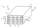
- 도 2는 도 1의 교환기에 관해 더욱 자세한 투시도를 개략적으로 나타낸다;2 schematically shows a more detailed perspective view of the exchanger of FIG. 1;
- 도 3은 도 2의 면 P2에서, 교환기의 공기순환망 일부에 대한 단면도이다; 3 is a cross-sectional view of a portion of the air circulation network of the exchanger, on face P2 of FIG. 2;
- 도 4는 도 2의 면 P1에서, 교환기 일부에 대한 단면도이다;4 is a cross-sectional view of a part of the exchanger, on face P1 of FIG. 2;
- 도 5는 도 2내지 4의 교환기 일부에 관한 투시도이다;5 is a perspective view of a part of the exchanger of FIGS. 2 to 4;
- 도 6은 교환기의 공기순환망을 형성하는 셀 1개에 관한 투시도이다; 그리고6 is a perspective view of one cell forming the air circulation network of the exchanger; And
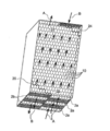
- 도 7은 도 2와 유사한, 본 발명의 다른 구체예에서의 교환기이다.7 is an exchanger in another embodiment of the invention, similar to FIG.
도 1은, 빌딩(102)에 설치된, 공기처리 및 조화 시스템(100)을 나타낸다. 상기 시스템(100)은 특히 본 발명에 따른 2중 공기흐름 교환기(1)를 포함한다. 상기의 경우에, 상기 교환기(1)는 빌딩(102)으로부터 발생하는 오염된 공기흐름 A 및 빌딩으로 들어오는 신선한 공기흐름 B 사이에서 열전달을 보장한다. 즉, 빌딩(102)에서 공기를 교체하는데 있어, 자체 열전달기(1)로 갖춘 시스템(100)은, 가정에서 배출된 오염된 공기 A로부터 열 또는 냉기를 회수하고, 유입되는 신선한 공기흐름 B에 상기 열 또는 냉기를 공급한다. 따라서, 시스템(100)은 빌딩(102)의 가열 또는 공기조화를 위해 낭비된 에너지를 보존하게 된다.1 shows an air treatment and
예를 들어, 오염된 공기흐름 A는 빌딩에서 배출되기 전에 22°C 일 수 있고, 신선한 공기흐름 B는 빌딩에 유입되기 전 0°C일 수 있다. 교환기에서의 열전달 후에, 상기 흐름 B는 빌딩에 유입되어 교환기에서 배출된 온도가 20°C에 도달 할 수 있고, 상기 흐름 A는 교환기 및 빌딩에서 배출되어 2°C로 냉각될 수 있다.For example, contaminated airflow A may be 22 ° C before exiting the building, and fresh airflow B may be 0 ° C before entering the building. After heat transfer in the exchanger, the flow B may enter the building and the temperature discharged from the exchanger may reach 20 ° C., and the flow A may be discharged from the exchanger and the building and cooled to 2 ° C.
도 1에서 상기 시스템(100)은 2개의 팬(fan, 104)에 의해 구성되어, 상기 팬은 흐름 A 및 B의 순환을 발생시킨다.In FIG. 1, the
상기 교환기(1)는, 더 습한 매체(medium)으로부터 더 건조한 매체를 향해 흐르는 상기 2개의 흐름 A 및 B 사이에서 수분전달을 제공하도록 설계된다. 따라서, 상기 교환기(1)는 전열 교환기 또는 엔탈피 교환기로서 자격을 갖추게 된다.The
도 2는, 축조방향(4)을 따라 서로의 위에 쌓인 다수의 공기 순환망(2a, 2b)을 포함하는 교환기(1)를 개략적으로 도시한다. 상기 망(2a, 2b)은 교대로 설치되고, 도 2에서 개략적으로 도시된 화살표와 같이, 오염된 공기 A의 순환과 유입하는 신선한 공기 B의 순환 각각을 위해 설계된다. 상기 교환기는 역류 교환기로서, 망(2a)에서의 흐름방향 A는 망(2b)에서의 흐름 방향 B와는 반대이다.2 schematically shows an
수증기에 대한 투과성과 공기에 대한 비투과성을 갖는 폴리머 멤브레인(6)은 방향(4)을 따라 서로가 연이어 놓인 망(2a, 2b) 사이에 제공된다. 따라서, 2개의 흐름 A 및 B 사이의 수분전달은 둘씩 짝을 지어 있는 망을 분리시키는 상기 멤브레인(6)을 통해 일어난다.A
그러므로, 망(2a, 2b) 사이에 삽입된 상기 멤브레인(6)은 상기 망에 의해 지지된다. 전체 스택(stack)은 케이지 또는 엔벨로프(cage or envelope, 8) 에 삽입되어, 누설방지(leak tightness)를 제공하며 망과 망(2a, 2b) 사이의 투과(communication)를 방지한다.Therefore, the
도 3 내지 도 6은 멤브레인(6) 및 망(2a, 2b)의 스택을 좀 더 자세하게 도시한 것이다.3 to 6 show the stack of the
전체적으로, 각 망(2a, 2b)은 축조방향(4)에 평행한 축(12)을 갖는 6각형 단면을 구비한 원통형 셀(10)이 존재하는 금속 벌집구조로 만들어진다. 결과적으로, 도 4 및 도 5에 도시된 바와 같이, 셀(10)의 최정상부 및 바닥부 모서리만이 멤브레인(6)과 접촉한다. In total, each
또한, 구조(2a, 2b)를 통하여 공기흐름을 순환시키기 위해, 상기 셀의 축(12)에 대하여 직각인 평면에서 셀을 형성하는 면의 적어도 일부는 천공되어야 한다. 상기 구멍(14)은 모든 면에 또는 오직 면의 일부분에만 제공되고, 바람직하게는 해당 면의 사각 중심에 놓이는 형태이다. 각 구멍(14)의 표면 영역은 구멍이 만들어지는 셀 면적의 40 내지 75 % 범위일 수 있다.In addition, in order to circulate the airflow through the
따라서, 도 3에 개략적으로 도시된바와 같이, 오염된 공기흐름 A는 구조 (2a)로부터 벗어나기 전에 상기 구조(2a)를 통해 불고, 구멍(14)을 통해 하나의 셀에서 다음 셀까지 통과한다. 명백하게, 신선한 공기흐름 B 역시 벌집구조(2b)를 통과하는 것은 마찬가지이다. 일반적으로, 상기 구성은 2개의 공기흐름 A 및 B 사이에서 열전달 및 수증기전달을 개선한다.Thus, as schematically shown in FIG. 3, the contaminated airflow A blows through the
특히 벌집구조로 인하여, 스택의 기계적 강도 또한 매우 만족스럽다. 또한, 상기 구조(2a, 2b)는 바람직하게는 서로로부터 오프셋(offset) 되므로 서로에 대해 직접 연이어 놓인 구조(2a, 2b)내의 상기 셀의 축(12)은 일치하지 않는다. 예를 들어, 축조방향을 따라 엇갈림 배열(staggered arrangement)이 선택되는데, 상기 배열에서 모든 구조(2a)는 상기 셀의 축(12)이 짝을 지어 일치하는 모양을 갖도록 모두 같은 위치에 놓이고, 구조(2b)도 또한 상기 셀의 축(12)이 짝을 지어 일치하는 모양을 갖도록 모두 같은 위치에 놓인다. 그럼에도 불구하고, 도 5와 같이, 각 구조(2a)는 축조방향(4) 및 상기 축조방향(4)에 수직인 평면 방향을 따라 연이어 인접한 구조(2b)로부터 오프셋된다. 상기 오프셋은 셀의 반쪽 너비(half-cell width)와 동일하거나 그에 근접할 수 있다.In particular due to the honeycomb structure, the mechanical strength of the stack is also very satisfactory. Further, the
본 발명은 천공면과 비천공면을 분별하여 선택함으로써 각 구조(2a, 2b) 내에서의 흐름 순환(flow circulation)에 대한 완벽한 제어를 제공한다. 예를 들어, 도 7의 다른 실시예에서, 공기흐름 분배구역 및 공기흐름 수집구역이 각 벌집구조(2a, 2b) 내에 형성된다.The present invention provides complete control over the flow circulation within each
구조(2a) 각각에 대하여, 상기 구조는, 상기 흐름 A의 주입구 모서리(inlet edge)에 인접한 몇 개 셀을 제외하고는, 상기 셀(10)의 면 각각에 구멍을 갖는다. For each
상부 구조 (2a)의 유입구 모서리(inlet edge) 우측 반쪽만이 구조로 유입되는 흐름 A를 위해 설계되고, 도 7과 같이 다른 반쪽은 폐쇄된다. 또한, 도 7의 회색 영역과 같이, 셀의 몇 개 면은 흐름 A의 분배구역(18)을 생성하기 위해 천공되지 않는다. 평면도에서 보는 바와 같이, 상기 면은 유입구 모서리 2개 반쪽 사이의 점합점에서 시작하여 흐름 A의 전체 방향에 대해 좌측으로 확장하는 라인(20)을 형성한다. 결과적으로, 분배구역(18)을 따르는 흐름은 밀폐선(air tight line, 20)을 따라 안내되어, 구조 반쪽으로부터 구조 전체 너비로 확장한다.Only the right half of the inlet edge of the
또한, 상부 구조(2a)의 배출구 좌측 반쪽만이 구조로부터 추출되는 흐름 A를 위해 설계되고, 7과 같이 다른 반쪽은 폐쇄된다. 또한, 몇 개 셀의 면은 도 7의 회색 영역과 같이, 흐름 A의 수집구역(22)을 생성하기 위하여 천공되지 않는다. 평면도에서 보는 바와 같이, 상기 면은 배출구 모서리(outlet edge)의 2개 반쪽사이의 접합점에서 시작하여 흐름 A방향의 반대 방향을 따라, 우측으로 확장하는 라인(24)을 형성한다. 결과적으로, 수집구역(22)을 따르는 흐름은 밀폐선(24)을 따라 안내되어, 구조 전체로부터 구조 반쪽 너비로 점차 좁아진다.In addition, only the left half of the outlet of the
상기 구성은 바람직하게는 모든 구조(2a)에 적용될 수 있는데, 반면 구조 (2b)는 상기 구성의 반대되는 구성을 취하도록 설계된다. 결과적으로, 도 7에서 흐름 A의 유입은 스택 우측 반쪽 전체높이에서 일어나는 반면, 흐름 A의 배출은 스택 좌측 반쪽 전체 높이에서 일어난다. 유사하게, 역류인 흐름 B의 유입은 스택의 우측 반쪽 전체 높이에서 일어나는 반면, 흐름 B의 배출은 스택 좌측 전체높이에서 일어난다. The configuration can preferably be applied to all
따라서, 교환기(1)의 전면은 흐름 A의 유입을 위한 우측 반쪽과 흐름 B의 유출을 위한 좌측 반쪽을 갖는 반면, 상기 교환기의 후면은 흐름 B의 유입을 위한 우측 반쪽과 흐름 A의 배출을 위한 좌측 반쪽을 갖는다. Thus, the front side of the
안내를 위해, 셀을 형성하기 위한 용접 이전에 벌집구조(2a, 2b)의 조립은 프레스(press)에 의한 물결모양의 알루미늄 또는 다른 금속으로 만들어진 플레이트/시트를 사용하여 종래와 같이 이뤄질 수 있다. 바람직하게 면의 상기 구멍은, 예를 들어 레이저 커팅(laser cutting)이나 워터 젯 커팅(water jet cutting) 또는 스탬핑(stamping)에 의한 프레싱 단계 전에 만들어진다.For guiding, the assembly of the
명백하게, 본 발명은 실시예에 한정되지 않으며, 당업자에 의한 본 발명에 대한 다양한 변경을 포함한다.
Apparently, the present invention is not limited to the examples, and includes various modifications to the present invention by those skilled in the art.
Claims (8)
상기 망(2a, 2b)의 적어도 1개는 2개의 측면이 상기 멤브레인(6) 2개와 연결된 벌집구조로부터 만들어지며, 상기 벌집구조는 상기 축조방향(4)과 평행한 축(12)을 구비한 원통형 셀(10)을 갖고, 벌집구조 내에서 공기가 통과할 수 있도록 상기 셀을 형성하는 적어도 몇 개의 면이 천공된 것을 특징으로 하는 2중 공기흐름 교환기.
Allows heat transfer and water transfer between the two air streams, and is separated in pairs by membranes 6 which are stacked on top of each other along the building direction 4 and are permeable to water vapor and impermeable to air. In a dual airflow exchanger (1) comprising a plurality of air circulation networks (2a, 2b),
At least one of the nets 2a, 2b is made from a honeycomb structure in which two sides are connected to two membranes 6, the honeycomb structure having an axis 12 parallel to the construction direction 4. A double airflow exchanger having a cylindrical cell (10), wherein at least some of the faces forming the cell are perforated to allow air to pass through within the honeycomb structure.
2. The double airflow exchanger according to claim 1, wherein the cylindrical cell has a hexagonal cross section. 3.
The double air according to any one of claims 1 to 2, wherein the air circulation inside the exchanger is designed to be co-current, cross current or counter-current. Flow exchanger.
4. The dual airflow exchanger according to claim 1, wherein the membrane is made of polymer or paper. 5.
5. The dual airflow exchanger as claimed in claim 1, wherein each of the nets is a honeycomb. 6.
The axis of the cell (1) according to any one of claims 1 to 5, wherein at least one of the networks (2a, 2b) is connected in the at least one of the adjacent networks (2a, 2b) consecutively along the construction direction (4). 12. A dual airflow exchanger having a cell axis 12 offset from 12).
The double airflow exchanger according to any one of claims 1 to 6, wherein each honeycomb structure is metal.
Applications Claiming Priority (3)
| Application Number | Priority Date | Filing Date | Title |
|---|---|---|---|
| FR1058092A FR2965897B1 (en) | 2010-10-06 | 2010-10-06 | DOUBLE AIR FLOW EXCHANGER WITH IMPROVED THERMAL TRANSFER AND HUMIDITY |
| FR1058092 | 2010-10-06 | ||
| PCT/EP2011/067272 WO2012045717A1 (en) | 2010-10-06 | 2011-10-04 | Exchanger with double air flow having improved transfers of heat and moisture |
Publications (1)
| Publication Number | Publication Date |
|---|---|
| KR20140001200A true KR20140001200A (en) | 2014-01-06 |
Family
ID=43939640
Family Applications (1)
| Application Number | Title | Priority Date | Filing Date |
|---|---|---|---|
| KR1020137007603A KR20140001200A (en) | 2010-10-06 | 2011-10-04 | Dual air flow exchanger with enhanced heat and humidity transfers |
Country Status (7)
| Country | Link |
|---|---|
| US (1) | US9194630B2 (en) |
| EP (1) | EP2625467B1 (en) |
| JP (1) | JP5905015B2 (en) |
| KR (1) | KR20140001200A (en) |
| BR (1) | BR112013007538A2 (en) |
| FR (1) | FR2965897B1 (en) |
| WO (1) | WO2012045717A1 (en) |
Families Citing this family (20)
| Publication number | Priority date | Publication date | Assignee | Title |
|---|---|---|---|---|
| ES2527826T3 (en) | 2012-01-20 | 2015-01-30 | Zehnder Verkaufs- Und Verwaltungs Ag | Heat exchanger element and production procedure |
| JP5797163B2 (en) * | 2012-07-09 | 2015-10-21 | 三菱電機株式会社 | Total heat exchange element and total heat exchanger |
| FR2993042B1 (en) | 2012-07-09 | 2014-08-22 | Commissariat Energie Atomique | DEVICE FOR REGULATING THE HUMIDITY LEVEL IN A SOLAR MODULE WITH A CONCENTRATION AND SOLAR MODULE COMPRISING AT LEAST ONE SUCH DEVICE |
| ES2685068T3 (en) | 2013-07-19 | 2018-10-05 | Westwind Limited | Heat exchanger / enthalpy element and method for production |
| FR3011624B1 (en) | 2013-10-09 | 2017-12-22 | Commissariat Energie Atomique | SYSTEM AND METHOD FOR PROCESSING AND CONDITIONING AIR |
| FR3024533B1 (en) * | 2014-07-31 | 2016-08-26 | Commissariat Energie Atomique | IMPROVED ENTHALPIC EXCHANGER |
| DE102014215908A1 (en) * | 2014-08-11 | 2016-02-11 | Mahle International Gmbh | Heat exchanger and pipe |
| US20220163272A1 (en) * | 2017-05-18 | 2022-05-26 | Kai Klingenburg | Heat-exchanger plate |
| DE102014017362A1 (en) * | 2014-11-24 | 2016-05-25 | Klingenburg Gmbh | Plate element for a plate heat exchanger |
| ES2805086T3 (en) * | 2014-12-18 | 2021-02-10 | Zehnder Group Int Ag | Heat exchanger and aviation apparatus with the same |
| PL226265B1 (en) * | 2015-05-11 | 2017-07-31 | Wojciech Cichobłaziński | Gravity dust recuperator |
| JP6570345B2 (en) * | 2015-07-06 | 2019-09-04 | 大阪瓦斯株式会社 | Air conditioning system |
| WO2017018948A1 (en) * | 2015-07-29 | 2017-02-02 | Mobiair Pte.Ltd. | Process and equipment capable to achieve zero-energy heating, ventilation, air conditioning operation |
| JP6566829B2 (en) * | 2015-10-09 | 2019-08-28 | 大阪瓦斯株式会社 | Air conditioning system |
| CN106440323B (en) * | 2016-11-01 | 2019-05-31 | 合肥海尔空调器有限公司 | A kind of stackable air-conditioning internal machine and air-conditioning system |
| CA3193016C (en) * | 2018-01-22 | 2023-10-10 | Energy Wall Llc | System, components, and methods for air, heat, and humidity exchanger |
| US20200132337A1 (en) * | 2018-10-31 | 2020-04-30 | Robert Scott KELLY | Covers for air conditioner units |
| US20220126263A1 (en) * | 2019-02-25 | 2022-04-28 | L'air Liquide, Société Anonyme Pour L'etude Et L'exploitation Des Precédés Georges Claude | Matrix integrating at least one heat exchange function and one distillation function |
| FR3093172B1 (en) * | 2019-02-25 | 2021-01-22 | L´Air Liquide Sa Pour L’Etude Et L’Exploitation Des Procedes Georges Claude | Heat and matter exchange apparatus |
| FR3093174B1 (en) * | 2019-02-25 | 2021-01-29 | L´Air Liquide Sa Pour L’Etude Et L’Exploitation Des Procedes Georges Claude | Method of manufacturing a heat and material exchange apparatus |
Family Cites Families (15)
| Publication number | Priority date | Publication date | Assignee | Title |
|---|---|---|---|---|
| US1869338A (en) * | 1930-03-13 | 1932-07-26 | Fedders Mfg Co Inc | Radiator corner construction |
| US4093435A (en) * | 1973-11-23 | 1978-06-06 | Wing Industries Inc. | Total heat energy exchangers |
| JPS59177119A (en) * | 1983-03-28 | 1984-10-06 | Nippon Soken Inc | Dehumidifying apparatus |
| JPS61252497A (en) * | 1985-04-22 | 1986-11-10 | Seibu Giken:Kk | Manufacture of element for dehumidification and total heat exchange |
| JPS6261881A (en) | 1985-09-11 | 1987-03-18 | Honda Motor Co Ltd | Rear wheel steering apparatus for vehicle |
| JPS6261881U (en) * | 1985-10-03 | 1987-04-17 | ||
| US5339653A (en) * | 1992-10-29 | 1994-08-23 | Degregoria Anthony J | Elastomer bed |
| CA2195282C (en) * | 1997-01-16 | 2004-05-11 | Frederic Lagace | Unitary heat exchanger for the air-to-air transfer of water vapor and sensible heat |
| WO2001027552A1 (en) * | 1999-10-08 | 2001-04-19 | Carrier Corporation | A plate-type heat exchanger |
| WO2001094864A1 (en) * | 2000-06-05 | 2001-12-13 | Stanhope Products Company | Polypropylene or polyester plastic desiccant cartridge with fiberglass filter and bead cage ends |
| JP3757976B2 (en) * | 2004-04-15 | 2006-03-22 | ダイキン工業株式会社 | Heat exchange unit |
| US20080271874A1 (en) * | 2007-05-04 | 2008-11-06 | John Gietzen | Thermal energy exchanger |
| WO2008037079A1 (en) * | 2006-09-29 | 2008-04-03 | Dpoint Technologies Inc. | Pleated heat and humidity exchanger with flow field elements |
| JP2009002575A (en) * | 2007-06-21 | 2009-01-08 | Fujikake Planning Co Ltd | Honeycomb panel and manufacturing method for it |
| US7824766B2 (en) * | 2007-11-20 | 2010-11-02 | Energy Wall, Llc | Sorption paper and method of producing sorption paper |
-
2010
- 2010-10-06 FR FR1058092A patent/FR2965897B1/en not_active Expired - Fee Related
-
2011
- 2011-10-04 EP EP11764543.2A patent/EP2625467B1/en active Active
- 2011-10-04 BR BR112013007538A patent/BR112013007538A2/en active Search and Examination
- 2011-10-04 US US13/824,646 patent/US9194630B2/en active Active
- 2011-10-04 JP JP2013532163A patent/JP5905015B2/en active Active
- 2011-10-04 KR KR1020137007603A patent/KR20140001200A/en not_active Application Discontinuation
- 2011-10-04 WO PCT/EP2011/067272 patent/WO2012045717A1/en active Application Filing
Also Published As
| Publication number | Publication date |
|---|---|
| EP2625467A1 (en) | 2013-08-14 |
| EP2625467B1 (en) | 2016-03-16 |
| US20130233514A1 (en) | 2013-09-12 |
| JP2013542397A (en) | 2013-11-21 |
| WO2012045717A1 (en) | 2012-04-12 |
| BR112013007538A2 (en) | 2016-07-19 |
| FR2965897A1 (en) | 2012-04-13 |
| JP5905015B2 (en) | 2016-04-20 |
| US9194630B2 (en) | 2015-11-24 |
| FR2965897B1 (en) | 2012-12-14 |
Similar Documents
| Publication | Publication Date | Title |
|---|---|---|
| KR20140001200A (en) | Dual air flow exchanger with enhanced heat and humidity transfers | |
| US10281162B2 (en) | Enthalpy exchanger including stacked networks and selectively permeable membranes | |
| US20230243526A1 (en) | Enthalpy exchanger | |
| DK2893284T3 (en) | CONSTRUCTION TO SUPPORT A MEMBRANE TO AN ENERGY EXCHANGE | |
| KR102068637B1 (en) | Heat exchanger element and method for the production | |
| US9140471B2 (en) | Indirect evaporative coolers with enhanced heat transfer | |
| US7497247B2 (en) | Heat exchanger | |
| US20080085437A1 (en) | Pleated heat and humidity exchanger with flow field elements | |
| US20150300754A1 (en) | Methods and systems for turbulent, corrosion resistant heat exchangers | |
| US9404689B2 (en) | Heat exchange matrix | |
| GB1595511A (en) | Exchanger for the transfer of sensible and/or latent heat | |
| CN102505437A (en) | Heat exchanger for clothes drying condensation and clothes dryer | |
| CN203224023U (en) | Channel-changed and efficiency-improved air total heat exchanger | |
| KR200384504Y1 (en) | Sensible heat exchanging block and device thereby | |
| KR20130016586A (en) | Heat exchanger for exhaust-heat recovery | |
| CN214612127U (en) | Sludge drying structure | |
| CN110006243B (en) | Evaporator and fruit and vegetable drying system | |
| KR100783616B1 (en) | Heat exchanger for exhaust-heat recovery | |
| EP3452760B1 (en) | Recuperator for exchange of energy between two air flows | |
| JP3156162U (en) | Total heat exchange element | |
| CN221484311U (en) | Water-collecting and defogging filler unit and cooling tower using same | |
| CN211119910U (en) | Air total heat energy exchange core structure based on field synergy theory | |
| JPH02290493A (en) | Heat exchanger | |
| US20220214114A1 (en) | Heat exchanger | |
| CN107588483A (en) | New air heat-exchange core body |
Legal Events
| Date | Code | Title | Description |
|---|---|---|---|
| WITN | Application deemed withdrawn, e.g. because no request for examination was filed or no examination fee was paid |