KR20130141664A - Robotic work object cell calibration device, system, and method - Google Patents
Robotic work object cell calibration device, system, and method Download PDFInfo
- Publication number
- KR20130141664A KR20130141664A KR1020137023867A KR20137023867A KR20130141664A KR 20130141664 A KR20130141664 A KR 20130141664A KR 1020137023867 A KR1020137023867 A KR 1020137023867A KR 20137023867 A KR20137023867 A KR 20137023867A KR 20130141664 A KR20130141664 A KR 20130141664A
- Authority
- KR
- South Korea
- Prior art keywords
- robot
- calibration device
- tool
- lasers
- projection
- Prior art date
Links
Images


Classifications
-
- B—PERFORMING OPERATIONS; TRANSPORTING
- B25—HAND TOOLS; PORTABLE POWER-DRIVEN TOOLS; MANIPULATORS
- B25J—MANIPULATORS; CHAMBERS PROVIDED WITH MANIPULATION DEVICES
- B25J9/00—Programme-controlled manipulators
- B25J9/16—Programme controls
- B25J9/1679—Programme controls characterised by the tasks executed
- B25J9/1692—Calibration of manipulator
-
- G—PHYSICS
- G05—CONTROLLING; REGULATING
- G05B—CONTROL OR REGULATING SYSTEMS IN GENERAL; FUNCTIONAL ELEMENTS OF SUCH SYSTEMS; MONITORING OR TESTING ARRANGEMENTS FOR SUCH SYSTEMS OR ELEMENTS
- G05B2219/00—Program-control systems
- G05B2219/30—Nc systems
- G05B2219/39—Robotics, robotics to robotics hand
- G05B2219/39033—Laser tracking of end effector, measure orientation of rotatable mirror
Abstract
로봇의 작업 오브젝트 셀 캘리브레이션 시스템은 툴 접점에서 교차하고 십자선(crosshair)으로 동작하는 한쌍의 빔-투사 레이저들을 방사하는 캘리브레이션 디바이스를 포함한다. 캘리브레이션 디바이스는 또한 네개의 평면-투사 레이저들을 방사하고, 그것들은 툴 접점에 관련하여 로봇 툴의 요, 피치, 및 롤을 조정하기 위해서 사용된다. 처음에, 캘리브레이션 디바이스는 작업 현장상의 고정물 또는 작업물위의 선택된 위치에 배치된다. 로봇의 작업 오브젝트 셀 캘리브레이션 방법은 오프라인 프로그래밍의 정확성을 증가시키고 로봇 교육 시간을 줄인다. 로봇의 작업 오브젝트 셀 캘리브레이션 시스템 및 방법은 보다 간단하고, 더 낮은 투자비를 수반하고, 종래 기술보다 더 낮은 운용비가 들고, 및 각각 로봇 툴에 대한 재캘리브레이션(recalibration)을 수행해야 할 필요 없이 작업 현장상의 상이한 로봇 툴들에 대하여 사용될 수 있다.The robot's work object cell calibration system includes a calibration device that emits a pair of beam-projection lasers that intersect at the tool contacts and act as crosshairs. The calibration device also emits four plane-projected lasers, which are used to adjust the yaw, pitch, and roll of the robotic tool in relation to the tool contact. Initially, the calibration device is placed at a fixture on the work site or at a selected location on the workpiece. The robot's work object cell calibration method increases the accuracy of offline programming and reduces robot training time. The robot's work object cell calibration system and method is simpler, involves lower investment costs, lower operating costs than the prior art, and does not require recalibration of each robotic tool on the shop floor. Can be used for different robotic tools.
Description
본 발명은 산업용 로봇을 위한 캘리브레이션 디바이스, 시스템, 및 방법에 관한 것으로, 보다 상세하게는, 작업 툴(working tool) 및 작업 위치(working position)를 감지하기 위한 시각적 센서를 갖는 촬상 장치(imaging device)가 제공된 산업용 로봇을 위한 캘리브레이션 디바이스, 시스템, 및 방법에 관한 것이다.TECHNICAL FIELD The present invention relates to a calibration device, system, and method for an industrial robot, and more particularly to an imaging device having a working tool and a visual sensor for sensing a working position. A calibration device, system, and method for an industrial robot provided.
자동차 산업에 의해 유도된 산업용 로봇들의 판매는, 이제 하수관 세정, 폭탄 감지, 및 복잡한 수술을 수행하는 것처럼 다양한 임무로 이동하고 있다. 판매된 유닛들의 수가 성장을 거듭하는 자동자, 금속, 및 전자 기기 산업에서 2010년에 120,000 유닛, 전년 숫자의 두배로 증가되었다. Sales of industrial robots driven by the automotive industry are now shifting to various tasks, such as performing sewer cleaning, bomb detection, and complex surgery. The number of units sold was 120,000 units in 2010, doubling the previous year's number in the growing automotive, metals, and electronics industries.
로봇들을 캘리브레이션하기 위한 종전의 접근법들은 오프라인 프로그램들에 앞서서 로봇 위치에 관련하여 작업물(work piece) 위치들을 측정하는 디바이스들 또는 로봇이 제작된 후에 로봇의 부정확성들을 측정하는 디바이스들을 사용한다.Previous approaches for calibrating robots use devices that measure work piece positions in relation to the robot position prior to offline programs or devices that measure the inaccuracies of the robot after the robot is built.
일부 종래 기술 시스템들은 하기를 포함한다; Some prior art systems include the following;
미국 특허 출원 번호 20090157226(de Smet)은 로봇 및 그것의 주변기기를 위한 로봇-셀 캘리브레이션 시스템을 개시한다. 시스템은 로봇 또는 그것의 주변기기에 부착되어 레이저 빔을 방사하는 에미터(emitter) 및 캘리브레이션을 수행하는 지점에 로봇 또는 그것의 주변기기에 마운트(mount)되어 레이저 빔을 수신하고 에미터 및 수신기 사이의 치수(dimension)를 결정하는 계산들을 수행하기 위한 수신기를 또한 포함한다. US Patent Application No. 20090157226 (de Smet) discloses a robot-cell calibration system for a robot and its peripherals. The system is attached to the robot or its peripherals to emit the laser beam and mounted to the robot or its peripherals at the point where calibration is performed to receive the laser beam and to measure the dimensions between the emitter and the receiver. It also includes a receiver for performing calculations to determine the dimension.
미국 특허 번호 6,408,252(de Smet)는 로봇 시스템을 캘리브레이션하기 위한 캘리브레이션 시스템 및 변위(displacement) 측정 디바이스를 개시한다. 시스템은 로봇 캘리브레이션 시스템과 함께 선형 변위 측정 디바이스를 포함한다. 선형 변위 측정 디바이스는 가늘고 긴(elongated) 부재, 드럼, 샤프트, 드럼 변위 메커니즘 및 드럼 회전 센서를 포함한다. 가늘고 긴 부재가 이동될 때 드럼이 회전하므로 드럼은 샤프트상의 축 방향으로(axially) 변위된다. 드럼 회전 센서는 가늘고 긴 부재가 이동한 거리에 관한 정확한 정보를 제공한다. 변위 측정 디바이스가 로봇의 디바이스의 캘리브레이션의 목적을 위한 캘리브레이션 시스템과 반복적인 방식으로 사용된다. US Patent No. 6,408,252 to de Smet discloses a calibration system and a displacement measurement device for calibrating a robotic system. The system includes a linear displacement measurement device in conjunction with a robot calibration system. The linear displacement measuring device includes an elongated member, a drum, a shaft, a drum displacement mechanism and a drum rotation sensor. The drum is rotated when the elongated member is moved so that the drum is displaced axially on the shaft. The drum rotation sensor provides accurate information about the distance traveled by the elongated member. The displacement measuring device is used in a repetitive manner with a calibration system for the purpose of calibrating the robot's device.
미국 특허 번호 6,321,137(de Smet)은 로봇 검사 시스템의 캘리브레이션을 위한 방법을 개시한다. 시스템은 생산 기준에 근거한 작업물들의 검사 동안에 로봇의 정확성을 유지하기 위해 작업물을 검사하는데 사용된다. 시스템은 로봇의 수학적 모델을 저장하기 위한 수단들, 타겟 위치를 측정하기 위한 수단들을 포함하여서 수학적 모델 및 타겟의 위치로부터의 입력에 기초하여 로봇을 캘리브레이션한다. US Patent No. 6,321,137 to de Smet discloses a method for calibration of a robotic inspection system. The system is used to inspect the workpiece to maintain the accuracy of the robot during inspection of the workpieces based on the production criteria. The system calibrates the robot based on input from the position of the mathematical model and the target, including means for storing the mathematical model of the robot, means for measuring the target position.
미국 특허 번호 6,044,308(Huissoon)은 툴 센서 수단들에 대하여 로봇 제어되는 툴의 툴 접점의 포즈(pose)를 캘리브레이션하기 위한 방법을 개시하며 로봇 제어되는 툴은 로봇의 엔드 포인트(end-point)에 부착된다. 툴 접점 센서는 툴 접점의 위치를 센싱하기 위해 기준 고정물에 대하여 미리 선택된 제2 포즈에 위치된다. 방법은 기준 고정물이 툴 센서의 FOV(Field of View)내에 있도록 툴 센서를 배치하는 단계; 및 기준 로봇 프레임에 대하여 로봇 엔드 포인트의 포즈(pose)를 계산하는 단계, 기준 고정물의 네개의 지형적으로 정의된 피쳐(feature)들의 센싱된 위치로부터 툴 센서에 대한 기준 고정물의 포즈를 계산하는 단계, 및 툴 접점 센서 수단들에 대하여 툴 접점의 감지된 위치로부터 기준 고정물에 대한 툴 접점의 위치를 계산하는 단계를 포함한다. US Pat. No. 6,044,308 to Hussoon discloses a method for calibrating the pose of a tool contact of a robot controlled tool with respect to tool sensor means and the robot controlled tool is attached to an end point of the robot. do. The tool contact sensor is located in a second preselected pose with respect to the reference fixture for sensing the position of the tool contact. The method includes positioning the tool sensor such that the reference fixture is within the field of view (FOV) of the tool sensor; And calculating a pose of the robot endpoint with respect to the reference robot frame, calculating a pose of the reference fixture relative to the tool sensor from the sensed positions of the four topographically defined features of the reference fixture, And calculating the position of the tool contact relative to the reference fixture from the sensed position of the tool contact relative to the tool contact sensor means.
이들 종래 기술의 시스템들은 일반적으로 비싼 장비 및 특화된 유저들을 수반하며 시간 소모적이다. These prior art systems generally involve expensive equipment and specialized users and are time consuming.
본 발명의 로봇의 작업 오브젝트 셀 캘리브레이션 디바이스, 시스템, 및 방법의 1차 목적은 오프라인 프로그램의 정확성을 증가시키고 및 로봇 학습 시간(teaching time)을 줄이는 것이다. 또한 본 발명의 로봇의 작업 오브젝트 셀 캘리브레이션 디바이스, 시스템, 및 방법의 다른 목적은 종래 기술보다 보다 낮은 투자비 및 운용 경비로 귀결되고 개선된 정밀성으로 귀결되는 보다 단순한 캘리브레이션 방법을 제공하는 것이다. The primary object of the work object cell calibration devices, systems, and methods of the robot of the present invention is to increase the accuracy of off-line programs and to reduce robot learning time. Another object of the work object cell calibration devices, systems, and methods of the robot of the present invention is also to provide a simpler calibration method that results in lower investment and operating costs than in the prior art and results in improved precision.
필요로 되는 것은 각각의 툴에 대한 재캘리브레이션(recalibration)을 수행하지 않고 작업 현장의 상이한 로봇 툴들을 이용하기 위한 로봇의 작업 오브젝트 셀 캘리브레이션 디바이스, 시스템, 및 방법이다. 필요로 되는 것은 로봇 툴의 정확성 또는 주변기기 장비의 위치를 결정하기 위한 추가의 컴퓨터들 또는 소프트웨어를 요구하지 않는 로봇의 작업 오브젝트 셀 캘리브레이션 디바이스, 시스템, 및 방법이며, 이것은 존재하는 BIW(body-in-white) 절차들, 직원 컴퓨터들 및 소프트웨어 및 종사자들(trades)간에 정보를 통신하는 방법들을 사용하고 배치에 대한 재교육(retraining) 없이 또는 거의 요구하지 않는다.What is needed is a robot's work object cell calibration device, system, and method for using different robotic tools on the job site without performing recalibration for each tool. What is needed is a work object cell calibration device, system, and method of a robot that does not require additional computers or software to determine the accuracy of the robot tool or the location of the peripheral equipment, which is a body-in-existing BIW. white) Uses methods of communicating information between procedures, employee computers and software, and trades and requires little or no retraining of placement.
본 발명의 로봇의 작업 오브젝트 셀 캘리브레이션 디바이스, 시스템, 및 방법은 이런 목적들 및 이런 요구들을 다룬다. The working object cell calibration device, system, and method of the robot of the present invention addresses these objects and these needs.
본 발명의 로봇의 작업 오브젝트 셀 캘리브레이션 시스템 및 방법에서 사용되는 캘리브레이션 디바이스는 처음에 로봇에 근접한 작업 현장상의 고정물 또는 작업물 위의 선택된 위치에 배치된다. The calibration device used in the work object cell calibration system and method of the robot of the present invention is initially placed at a selected location on a fixture or workpiece on a work site proximate to the robot.
본 발명의 제1 바람직한 실시예에서, 캘리브레이션 디바이스는 중심 프레임으로부터 연장되는 E-형상 확장부분(extension)으로부터 한쌍의 빔-투사 레이저들을 방사한다. 빔-투사 레이저들은 툴 접점에서 교차하는 십자선(crosshair)으로서 역할을 한다. 캘리브레이션 디바이스는 한쌍의 대향하는 프레임 말단들을 포함하는 수평 프레임 부재, 및 한쌍의 대향하는 프레임 말단들을 포함하는 수직 프레임 부재를 포함한다. 평면-투사 레이저는 바람직하게는 각 프레임 말단에 각각 배치되고 및 투사되는 레이저 평면은 각각의 평면-투사 레이저들로부터, 개별적으로 방사된다. 평면-투사 레이저들은 작업 현장상의 툴 접점에 위치된 로봇 툴의 롤(roll), 요(yaw), 및 피치(pitch)를 조정하기 위해 사용된다. In a first preferred embodiment of the invention, the calibration device emits a pair of beam-projection lasers from an E-shaped extension extending from the center frame. Beam-projection lasers serve as crosshairs that cross at tool contacts. The calibration device comprises a horizontal frame member comprising a pair of opposing frame ends, and a vertical frame member comprising a pair of opposing frame ends. Planar-projection lasers are preferably arranged respectively at the end of each frame and the projected laser plane is emitted separately from the respective plane-projection lasers. Planar-projection lasers are used to adjust the roll, yaw, and pitch of a robotic tool located at a tool contact on the shop floor.
캘리브레이션 디바이스를 이용하여 로봇을 캘리브레이션하기 위한 방법은:The method for calibrating a robot using a calibration device is:
첫번째, 에미터(emitter)를 고정물에 부가한다. 로봇의 캘리브레이션 제어 유닛 또는 제어 인터페이스를 갖는 랩탑 컴퓨터를 이용하여, 툴 접점이 캘리브레이션 디바이스로부터 방사된 수평 빔-투사 레이저들에 정렬된다. First, add an emitter to the fixture. Using a robot's calibration control unit or laptop computer with a control interface, the tool contacts are aligned with the horizontal beam-projected lasers emitted from the calibration device.
수평 및 수직 평면-투사 레이저들을 이용하여, 로봇 툴을 롤, 요, 및 피치에 대하여 정렬한다. 이것이 수행된 후에, 좌표들을 표시하고, 이 위치를 로봇을 제어하기 위해서 사용되는 랩탑상의 제어 패널의 또는 로봇 제어 유닛의 제로(0) 위치로서 설정한다. 이것은 로봇이 그것의 작업 경로를 위해 사용할 지점을 설정한다. 지점이 설정된 후에, 로봇 작업 경로가 사용될 준비가 된다.Using horizontal and vertical plane-projection lasers, the robot tool is aligned with respect to roll, yaw, and pitch. After this is done, the coordinates are displayed and set to this position as the zero position of the control panel on the laptop or the robot control unit used to control the robot. This sets the point the robot will use for its work path. After the point is set, the robotic work path is ready for use.
이제, 캘리브레이션을 테스트한다. 만약 로봇이 어쨌든 캘리브레이션 디바이스에 충돌하지 않고 의도된 동작들을 완성하면, 캘리브레이션은 완료된다. 만약 그렇지 않으면, 작업 경로가 적절하게 설정될 때까지 상기에서 언급한 것을 반복한다.Now test the calibration. If the robot completes the intended actions without colliding with the calibration device anyway, the calibration is complete. If not, repeat the above steps until the working path is set appropriately.
로봇의 작업 오브젝트 셀 캘리브레이션 시스템은 캘리브레이션 디바이스를 포함한다. 캘리브레이션 디바이스는 수평으로 배치된 중심 프레임으로부터 연장되는 E-형상 확장부분(extension)으로부터 한쌍의 빔-투사 레이저들을 방사한다. 빔-투사 레이저들은 툴 접점에서 교차하는 십자선(crosshair)으로서 역할을 한다. 캘리브레이션 디바이스는 한쌍의 대향하는 프레임 말단들을 포함하는 수평 프레임 부재, 및 한쌍의 대향하는 프레임 말단들을 포함하는 수직 프레임 부재를 포함한다. 평면-투사 레이저는 바람직하게는 각 프레임 말단에 각각 배치되고 및 투사되는 레이저 평면은 각각의 평면-투사 레이저들로부터, 개별적으로 방사된다. 평면-투사 레이저들은 툴 접점에 관련하여 로봇 툴의 롤, 요, 및 피치를 조정하기 위해 사용된다. The robot's work object cell calibration system includes a calibration device. The calibration device emits a pair of beam-projection lasers from an E-shaped extension extending from the horizontally arranged center frame. Beam-projection lasers serve as crosshairs that cross at tool contacts. The calibration device comprises a horizontal frame member comprising a pair of opposing frame ends, and a vertical frame member comprising a pair of opposing frame ends. Planar-projection lasers are preferably arranged respectively at the end of each frame and the projected laser plane is emitted separately from the respective plane-projection lasers. Planar-projection lasers are used to adjust the roll, yaw, and pitch of the robotic tool in relation to the tool contact.
본 발명의 로봇의 작업 오브젝트 캘리브레이션 시스템 및 방법에서의 사용을 위한 캘리브레이션 디바이스의 제2 및 제3 바람직한 실시예는 수평 프레임 말단들 또는 수직 프레임 말단들에 부착된 단지 두개의 평면-투사 레이저들을 포함한다. 만약 단지 두개의 평면-투사 레이저들이 사용되면, 조절은 상기 캘리브레이션 디바이스의 상기 쌍의 평면-투사 레이저들을 이용함으로써 로봇 툴의 롤 및 요, 롤 및 피치, 또는 요 및 피치에 한정된다. The second and third preferred embodiments of the calibration device for use in the work object calibration system and method of the robot of the present invention include only two plane-projected lasers attached to the horizontal frame ends or the vertical frame ends. . If only two plane-projection lasers are used, the adjustment is limited to the roll and yaw, roll and pitch, or yaw and pitch of the robotic tool by using the pair of plane-projection lasers of the calibration device.
본 발명의 로봇의 작업 오브젝트 캘리브레이션 시스템 및 방법에서의 사용을 위한 캘리브레이션 디바이스의 제4 바람직한 실시예는 캘리브레이션 디바이스 중간에 부착된 단지 하나의 평면-투사 레이저를 포함한다. 레이저 헤드는 360° 회전 가능하고 로봇 툴을 x-축 상에서 먼저, 이어서 레이저 헤드가 회전된 후에 y-축 상에서 정렬되게 하는 것을 가능하게 한다. A fourth preferred embodiment of a calibration device for use in the work object calibration system and method of the robot of the present invention comprises only one plane-projected laser attached in the middle of the calibration device. The laser head is rotatable 360 ° and makes it possible to allow the robot tool to be aligned on the y-axis first on the x-axis and then after the laser head is rotated.
본 발명의 로봇의 작업 오브젝트 셀 캘리브레이션 디바이스, 시스템, 및 방법의 완전한 이해를 위해서, 참조 부호가 발명의 요약에 이은 상세한 설명 및 첨부한 도면들에 제공되고 곧 바람직한 본 발명의 실시예들이 예시 방식으로 도시된다. 발명은 그것의 본질적인 특성들의 취지로부터 벗어나지 않는 많은 형태들로 구체화할 수 있고, 이것은 도면들은 단지 예시 및 설명의 목적들을 위하여 및 발명의 범위들을 정의하는 것으로 의도되지 않는다 것은 명백하게 이해된다.For complete understanding of the work object cell calibration device, system, and method of the robot of the present invention, reference numerals are provided in the following description of the invention and the accompanying drawings in which preferred embodiments of the present invention are provided by way of example. Shown. The invention may be embodied in many forms without departing from the spirit of its essential characteristics, and it is clearly understood that the drawings are not intended for the purposes of illustration and description only and to define the scope of the invention.
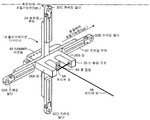
도 1은 캘리브레이션 디바이스와 툴 접점을 정렬하기 위해 사용되는 두개의 빔-투사 레이저들을 갖는, 본 발명의 로봇의 작업 오브젝트 캘리브레이션 시스템 및 방법의 캘리브레이션 디바이스의 제1 바람직한 실시예를 도시한다.
도 2는 캘리브레이션 디바이스의 끝단(extremity)들로부터 방사된 네개의 평면-투사 레이저를 갖는 도 1의 로봇의 작업 오브젝트 캘리브레이션 시스템 및 방법의 캘리브레이션 디바이스의 제1 바람직한 실시예를 도시한다.
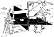
도 3은 도 1의 로봇의 작업 오브젝트 캘리브레이션 시스템 및 방법의 캘리브레이션 디바이스의 제1 바람직한 실시예의 분해도를 도시하고, 추가로 두개의 빔-투사 레이저들로 정렬된 용접건(weld gun)의 툴 접점을 갖는 용접건을 도시한다.
도 4는 도 3의 로봇의 작업 오브젝트 캘리브레이션 시스템 및 방법의 캘리브레이션 디바이스의 제1 바람직한 실시예의 분해도를 도시하고, 용접건 툴 헤드의 롤(roll), 요(yaw), 및 피치(pitch)를 조정하기 위해 캘리브레이션 디바이스의 끝단들로부터 방사된 두개 쌍들의 평면-투사 레이저들의 추가를 더 도시한다.
도 5는 도 1의 로봇의 작업 오브젝트 캘리브레이션 시스템 및 방법의 캘리브레이션 디바이스의 제1 바람직한 실시예의 조립도(assembly view)를 도시하고, 툴 접점을 이용하여 두개의 빔-투사 레이저들에 정렬된 로봇 툴 헤드에 대해 고정물(fixture)상에 마운트되는 캘리브레이션 디바이스를 추가로 도시한다.
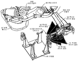
도 6은 도 5의 로봇의 작업 오브젝트 캘리브레이션 시스템 및 방법의 캘리브레이션 디바이스의 제1 바람직한 실시예의 조립도를 도시하고, 로봇의 툴 헤드의 롤(roll), 요(yaw), 및 피치(pitch)를 조정하기 위해 사용되는 네개의 평면-투사 레이저들을 추가로 도시한다.
도 7은 도 1의 로봇의 작업 오브젝트 캘리브레이션 시스템 및 방법의 캘리브레이션 디바이스의 제1 바람직한 실시예의 다른 분해도를 도시하고, 툴 접점 정렬 레이저들 및 롤, 요, 및 피치 정렬 레이저들에 정렬된 로봇 툴에 대해 고정물(fixture)상에 마운트되는 캘리브레이션 디바이스를 추가로 도시한다.
도 8은 본 발명의 로봇의 작업 오브젝트 캘리브레이션 시스템 및 방법의 캘리브레이션 디바이스의 제2 바람직한 실시예의 조립도, 캘리브레이션 디바이스의 수평 축을 따라 방사되는 두개 평면-투사 레이저들, 툴 접점에서 교차하는 한쌍의 빔-투사 레이저들, 수평 평면-투사 레이저들의 이 쌍 및 툴 접점에 정렬되는 로봇 툴을 도시한다.
도 9는 본 발명의 로봇의 작업 오브젝트 캘리브레이션 시스템 및 방법의 캘리브레이션 디바이스의 제3 바람직한 실시예의 조립도, 캘리브레이션 디바이스의 수직 축을 따라 방사되는 두개 평면-투사 레이저들, 툴 접점에서 교차하는 한쌍의 빔-투사 레이저들, 수직 평면-투사 레이저들의 이 쌍 및 툴 접점에 정렬되는 로봇 툴을 도시한다.
도 10은 본 발명의 로봇의 작업 오브젝트 캘리브레이션 시스템 및 방법의 캘리브레이션 디바이스의 제4 바람직한 실시예, 캘리브레이션 디바이스의 수직 축을 따라 방사되는 하나의 평면-투사 레이저, 툴 접점에서 수직 평면-투사 레이저들 중 하나에 교차하는 빔-투사 레이저를 도시한다.
도 11a는 도 1의 캘리브레이션 디바이스가 없는 종래 기술의 실시예의 작업 현장상에서의 사용을 위한 로봇 및 고정물을 도시하고, 및 도면들 11b 및 11b 는 본 발명에서 사용된 캘리브레이션 디바이스를 갖는 유사한 로봇, 고정물을 도시하고, 간략화된 방식에서 캘리브레이션 고정물 및 로봇 사이의 경로를 캘리브레이션하고 새로운 제로(0) 위치를 획득하기 위해 어떻게 사용되는지를 보여준다.1 shows a first preferred embodiment of a calibration device of the work object calibration system and method of the robot of the present invention, having two beam-projection lasers used to align the calibration device with the tool contact.
FIG. 2 shows a first preferred embodiment of a calibration device of the robot's work object calibration system and method of FIG. 1 with four plane-projected lasers emitted from extremities of the calibration device.
FIG. 3 shows an exploded view of a first preferred embodiment of a calibration device of the work object calibration system and method of the robot of FIG. 1, further showing the tool contact of a weld gun aligned with two beam-projection lasers. The welding gun having is shown.
FIG. 4 shows an exploded view of a first preferred embodiment of a calibration device of the work object calibration system and method of the robot of FIG. 3, adjusting the roll, yaw, and pitch of the welding gun tool head. To further illustrate the addition of two pairs of plane-projected lasers emitted from the ends of the calibration device.
FIG. 5 shows an assembly view of a first preferred embodiment of a calibration device of the work object calibration system and method of the robot of FIG. 1, with a robot tool aligned to two beam-projection lasers using tool contacts; FIG. Further shown is a calibration device mounted on a fixture relative to the head.
FIG. 6 shows an assembly view of a first preferred embodiment of a calibration device of the work object calibration system and method of the robot of FIG. 5, illustrating the roll, yaw, and pitch of the robot's tool head; FIG. Further shown are four plane-projected lasers used to adjust.
FIG. 7 shows another exploded view of a first preferred embodiment of a calibration device of the work object calibration system and method of the robot of FIG. 1, with a robot tool aligned to tool contact alignment lasers and roll, yaw, and pitch alignment lasers. Further shown is a calibration device mounted on a fixture.
8 is an assembly view of a second preferred embodiment of a calibration device of the work object calibration system and method of the robot of the present invention, two plane-projected lasers emitted along the horizontal axis of the calibration device, a pair of beams intersecting at the tool contact. The robotic tool is aligned to this pair of projection lasers, horizontal plane-projection lasers and the tool contact.
9 is an assembly view of a third preferred embodiment of a calibration device of the work object calibration system and method of the robot of the present invention, two plane-projected lasers emitted along the vertical axis of the calibration device, a pair of beams intersecting at the tool contact. The robot tool is aligned with this pair of projection lasers, vertical plane-projection lasers and the tool contact.
10 is a fourth preferred embodiment of a calibration device of the work object calibration system and method of the robot of the present invention, one plane-projected laser emitted along the vertical axis of the calibration device, one of the vertical plane-projected lasers at the tool contact. A beam-projection laser intersecting at is shown.
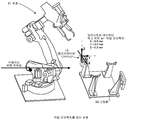
FIG. 11A shows a robot and fixture for use on the job site of the prior art embodiment without the calibration device of FIG. 1, and FIGS. 11B and 11B show a similar robot, fixture having a calibration device used in the present invention. It is shown and shows how it is used to calibrate the path between the calibration fixture and the robot and to obtain a new zero position in a simplified manner.
이제 도면들과 관련하여, 도면 1 및 2는 본 발명의 로봇의 작업 오브젝트 캘리브레이션 시스템 및 방법의 캘리브레이션 디바이스(10)의 제1 바람직한 실시예를 개시한다. 캘리브레이션 디바이스(10)는 툴 접점(공간상에서의 지점)(60)에 기초하여 로봇 툴의 작업 경로를 캘리브레이션하기 위해 사용된다. 공간상의 알려진 지점(60)은 세개의 차원들(X, Y, 및 Z)로 그리고 그것들의 회전 축들 Rx(피치), Ry(요), 및 Rz(롤)에 관련하여 정의된다. Referring now to the drawings, FIGS. 1 and 2 disclose a first preferred embodiment of a
캘리브레이션 디바이스(10)는 한쌍의 대향하는 프레임 말단(end)들(32A 및 32B)을 포함하는 수평 프레임 부재(22) 및 한쌍의 대향하는 프레임 말단들(32C 및 32D)을 포함하는 수직 프레임 부재(24)를 포함한다. 평면-투사 레이저(41, 42, 43, 및 44)는 바람직하게는 각 프레임 말단(32A, 32B, 32C, 및 32D)에 각각 배치되고 그리고 투사되는 레이저 평면(51, 52, 53, 및 54)이 평면-투사 레이저들(41, 42, 43, 및 44)의 각각으로부터 개별적으로 방사된다. The
수평 프레임 부재(22)를 따라 연장되는 것은 수평 프레임 부재(22) 및 수직 프레임 부재(24)에 관련하여 일반적으로 중심에 배치되고 수평으로 정렬되는 사각화된 "E-형상" 구조(25)를 형성하기 위해 결합하는 병렬의 세개의 암(arm)들이 있다. E-형상 구조(25)의 중앙 암(넘버링 되지 않은)은 두개의 말단 암들(26A 및 26B)보다 짧다. Extending along the horizontal frame member 22 is a squared "E-shaped" structure 25 generally centered and horizontally aligned with respect to the horizontal frame member 22 and the vertical frame member 24. There are three arms in parallel that combine to form. The central arm (not numbered) of the E-shaped structure 25 is shorter than the two terminal arms 26A and 26B.
제1 빔-투사 레이저(58)는 캘리브레이션 디바이스(10)의 중앙 근접점(proximate)에 배치된 "E-형상" 구조(25)의 단축된 중앙 암으로부터 방사된다. 제2 의 빔-투사 레이저(56)는 E-형상 구조(25)의 암들 중 하나(26A)로부터 방사되고 대향하는 암(26B)으로 향한다. The first beam-
제1 빔-투사 레이저(58)는 세개의 차원들로 정의된 X, Y, 및 Z 좌표들에 관련하여 공간상의 알려진 지점(60)에서 제2 빔-투사 레이저(56)와 기본적으로 수직이고 동일 평면상에 있고 교차한다. The first beam-
도 2에 도시된 바람직한 실시예에서, "E-형상" 구조(25)는 수평 프레임 부재 (22) 및 수직 프레임 부재(24)의 중심에 위치되기 때문에, 레이저 빔(58)은 프레임 말단들(32A 및 32B)에서 방사되는 평면-투사 레이저들(41 및 42)로부터 방사된 두개의 투사되는 레이저 평면들(51 및 52)과 본질적으로 동일평면에 있다. 유사하게, 빔-투사 레이저(58)는 프레임 말단들(32C 및 32D)에서 방사되는 평면-투사 레이저들(43 및 44)로부터 방사된 두개의 투사되는 레이저 평면들(53 및 54)과 본질적으로 동일평면에 있다. 캘리브레이션 디바이스(10)는 고정물(90) 상에 마운트되고 로봇의 작업 경로가 공간상의 알려진 지점(60)에 관련하여 캘리브레이션되는 것을 가능하게 한다. In the preferred embodiment shown in FIG. 2, since the "E-shaped" structure 25 is located at the center of the horizontal frame member 22 and the vertical frame member 24, the
평면-투사 레이저들(41, 42, 43, 및 44)은 캘리브레이션 디바이스(10)의 프레임 말단들(32A, 32B, 32C, 및 32D, 각각)로부터 네개의 투사되는 레이저 평면들 (51, 52, 53, 및 54, 각각)을 투사한다. 평면-투사 레이저들(41, 42, 43, 및 44)은 포커스된(focused) 라인들(3.5v-4.5v 16mm 5mw)을 갖는 레드(red) 레이저 모듈들이다. The planar-projection lasers 41, 42, 43, and 44 are four projected laser planes 51, 52, from the frame ends 32A, 32B, 32C, and 32D, respectively, of the
빔-투사 레이저들(56 및 58)은 캘리브레이션 디바이스(10)의 암(26A)으로부터 방사된 두개의 레이저 빔들을 투사하여 초점을 맞출 수 있는 지점들이다. 빔-투사 레이저들(56 및 58)은 초점을 맞출 수 있는 도트(dot)들(3.5v-4.5v 16mm 5mw)을 갖는 레드 레이저 모듈들이다. Beam-
도 3은 용접건과의 사용을 위한 캘리브레이션 디바이스(10)의 분해도를 도시한다. 용접건의 툴 접점(60)은 두개의 빔-투사 정렬 레이저들(56 및 58)과 정렬된다. 도 4는 로봇 툴 헤드(80)의 롤, 요, 및 피치를 조정하기 위해 평면-투사 레이저들(41, 42, 43, 및 44, 각각)로부터의 네개의 투사되는 레이저 평면들(51, 52, 53, 및 54, 각각)의 추가를 더 도시한다. 3 shows an exploded view of the
도 5는 고정물(90)상에 마운트되는 캘리브레이션 디바이스(10)를 도시한다. 로봇 툴 헤드(80)는 툴 접점(60)을 이용하여 두개의 빔-투사 레이저들(56 및 58)에 정렬된다. 도 6은 작업물(10)의 평면-투사 레이저들(41, 42, 43, 및 44, 각각)로부터의 네개의 투사되는 레이저 평면들(51, 52, 53, 및 54, 각각)을 더 도시하고, 그것들은 로봇 툴 헤드(80)의 롤, 요, 및 피치를 조정하기 위해 사용된다. 5 shows a
도 7은 X, Y, 및 Z 좌표들을 설정하는 툴 접점(60) 정렬 레이저 빔들(56 및 58)에 정렬된 로봇 툴(80)과 고정물(90)상에 마운트된 캘리브레이션 디바이스(10)를 도시한다. 7 shows a
도 8은 본 발명의 로봇의 작업 오브젝트 캘리브레이션 방법에서의 사용을 위한 캘리브레이션 디바이스(110)의 제2의 바람직한 실시예를 도시한다. 이 실시예에서, 두개의 투사되는 레이저 평면들(51 및 52)이 캘리브레이션 디바이스(110)의 프레임 부재(32)의 수평 축을 따라 두개의 평면-투사 레이저들(41 및 42, 각각)로부터 방사된다. 로봇 툴(80)은 투사되는 레이저 평면들(51 및 52)의 이 쌍 및 툴 접점(60)에 정렬된다. 8 shows a second preferred embodiment of a
도 9는 본 발명의 로봇의 작업 오브젝트 캘리브레이션 방법에서의 사용을 위한 캘리브레이션 디바이스(210)의 제3 바람직한 실시예를 도시한다. 이 실시예에서, 두개의 투사되는 레이저 평면들(53 및 54)이 캘리브레이션 디바이스(210)의 프레임 부재(24)의 수직 축을 따라 두개의 평면-투사 레이저들(43 및 44, 각각)로부터 방사된다. 로봇 툴(80)은 투사되는 레이저 평면들(53 및 54)의 이 쌍 및 툴 접점(60)에 정렬된다. 9 shows a third preferred embodiment of a
도 10은 본 발명의 로봇의 작업 오브젝트 캘리브레이션 방법에서의 사용을 위한 캘리브레이션 디바이스(310)의 또 다른 바람직한 실시예를 도시한다. 이 실시예에서는, 하나의 평면 투사되는 레이저(51)가 캘리브레이션 디바이스(310)의 수직 축을 따라 평면-투사 레이저(43)로부터 방사된다. 빔-투사 레이저(56)는 툴 접점(60)에서 수직 평면-투사 레이저(53)와 교차한다. 평면-투사 레이저(51)는 360° 회전 가능한 회전하는 헤드(head)를 가져서, 로봇 툴이 x-축 상에서 먼저, 이어서 레이저 헤드가 회전된 후에 y-축 상에서 정렬되는 것을 가능하게 한다. 10 shows another preferred embodiment of a calibration device 310 for use in a method of calibrating a work object of a robot of the present invention. In this embodiment, one planar projected
도 11a는 본 발명의 캘리브레이션 디바이스 없는 종래 기술의 실시예의 작업현장에서의 사용을 위한 로봇(81) 및 고정물(90)을 도시한다. 도면 11b 및 11c 는 캘리브레이션 디바이스(10)를 갖는 유사한 로봇(81), 및 고정물(90)을 도시하고, 고정물(90) 및 로봇(81) 사이의 경로를 캘리브레이션하고 그리고 새로운 제로(0) 위치를 획득하기 위해서 어떤 간략화된 방식으로 캘리브레이션 디바이스(10)가 사용되는지를 도시한다.11A shows a robot 81 and a
CAD 시뮬레이션 소프트웨어 사용하여, CAD 유저는 툴에 대한 위치를 다른 기계 설비(tooling)와 충돌을 피하기 위해 및 로봇(81) 또는 기계 설비 암 말단(end-of-arm)에 대한 액세스를 용이하게 하기 위해 가장 적합한 장소로 선택한다. 오프라인 프로그램들이 그런 다음 캘리브레이션 디바이스(10)에 대하여 다운로드 된다. 캘리브레이션 디바이스(10)는 그런 다음 작업 현장에서의 CAD 유저에 의해 정의된 위치내 툴 또는 작업물 위에 배치된다. 로봇 기술자(technician)는 이어서 로봇 툴 (80) 툴의 접점(60)을 디바이스 내로 조작하고 CAD계(world) 및 작업현장 사이의 편차를 획득하기 위해서 그것을 빔-투사 레이저들(56 및 58)에 정렬한다. 이 편차는 이어서 로봇(81) 내로 입력되고 및 새로운 캘리브레이션 디바이스(10)를 정의하는데 사용된다. 이것이 오프라인 프로그램들을 캘리브레이션하고 및 툴, 고정물, 및 주변기기의 거리 및 방위(orientation)를 정의한다. Using CAD simulation software, CAD users can position the tool to avoid collision with other tooling and to facilitate access to the robot 81 or the machine end-of-arm. Choose the most suitable place. Offline programs are then downloaded to the
고정물(90) 위의 캘리브레이션 디바이스(10)와 오프라인 프로그래밍은 캘리브레이션 디바이스(10)가 로봇(81)에 관련하여 고정물(90)의 "실제(real world) 위치"로 수정되는 것을 가능하게 한다. 만약 고정물(90)이 여하튼 움직여야 할 필요가 있거나 또는 뜻하지 않게 부딪히면, 조절하기 하기 위해서 캘리브레이션 디바이스(10) 및 전체 경로 이동(shift)들을 간단하게 수정한다. The
본 발명의 로봇 작업 셀 캘리브레이션들 방법은 한정되는 것은 아니지만, ROBCAD, Process Simulate, DELMIA, Roboguide 및 RobotStudio CAD 소프트웨어를 포함하는 로봇의 시뮬레이션 패키지들과 호환 가능하다. The method of robotic work cell calibrations of the present invention is not limited, but is compatible with simulation packages of robots including ROBCAD, Process Simulate, DELMIA, Roboguide and RobotStudio CAD software.
빔-투사 레이저들(56 및 58) 및 투사되는 레이저 평면들(51, 52, 53, 및 54)은 로봇 툴(80)의 알려진 피쳐(feature)들로 투사되고, 및 이어서 로봇 툴(80)의 경로를 캘리브레이션하기 위해 이용되고 로봇 툴(80)에 관련하여 고정물(90)의 관계(relationship)를 측정한다. Beam-
CAD 유저는 처음에 다른 기계설비와 사고들을 피하고 로봇 또는 기계설비 암의 말단(end-of-arm)을 위한 액세스의 용이를 위해서 툴 또는 작업물 위에 가장 적합한 위치를 선택한다. 캘리브레이션 디바이스(10)는 바람직하게는 표준 NAMM의 홀 패턴 마운트(40)를 이용하여 고정물(90)상에 마운트한다. 마운트들은 마운트 파트(part)들에 대하여 홀 사이즈들의 정확한 일치를 보장하기 위해서 레이저 절단(laser cut)된다. The CAD user initially chooses the most suitable location on the tool or workpiece to avoid other hardware and accidents and to facilitate access for the end-of-arm of the robot or hardware arm. The
본 발명의 캘리브레이션 디바이스(10)는 공간에서의 제로(0) 지점, 제로(0) 기준 프레임, 및 제로(0) 이론적인 프레임을 갖고, 이것이 고정물(90)위에 배치된다.The
캘리브레이션 디바이스(10)는 고정물(90) 위에 배치되고, 고정물(90)에 대한 로봇 툴(80)의 "실제(real-world)" 관계 획득하고 동시에 이 "실제" 위치로 캘리브레이션 디바이스(10)를 업데이트 함으로써 용접건의 툴 접점을 캘리브레이션 디바이스(10) 내의 특정 방위에 맞추어지는 것을 시각적으로 가능하게 한다. The
본 발명의 로봇의 작업 오브젝트 셀 캘리브레이션 시스템은 로봇 툴(80)의 경로를 캘리브레이션하기 위해서 캘리브레이션 디바이스(10)의 위치가 로봇 툴 (80)의 위치와 상관되고 동시에 로봇 툴(80)에 관련하여 고정물(90)의 "실제(real-world)" 거리 및 방위를 획득하는 것을 필요로 한다. The work object cell calibration system of the robot of the present invention has a position in which the
로봇의 작업 오브젝트 셀 캘리브레이션 방법은 캘리브레이션 디바이스(10)와 로봇 툴(80)을 배치하고 편차(difference)를 결정한다. The work object cell calibration method of the robot arranges the
본 발명의 로봇의 작업 오브젝트 셀 캘리브레이션 방법은 "알려진" 캘리브레이션 디바이스 또는 프레임(로봇의 시뮬레이션 CAD 소프트웨어 제공된 캘리브레이션 디바이스)을 캘리브레이션하기 위해 사용된다. 본 발명의 로봇의 작업 오브젝트 셀 캘리브레이션 방법은 알려진 X, Y, 및 Z 위치로 레이저 빔들을 투사함으로써 및 툴 접점(60)에 관련하여 로봇 툴(80)의 롤, 요, 및 피치를 조정하는데 알려진 기하학적 평면들을 정의함으로써 동작한다. The work object cell calibration method of the robot of the present invention is used to calibrate a "known" calibration device or frame (calibration device provided by the simulation CAD software of the robot). The work object cell calibration method of the robot of the present invention is known for adjusting the roll, yaw, and pitch of the
레이저가 로봇 암 기계설비의 로봇의 말단으로(용접건들, 물질 핸들러들, 미그(mig) 토오치들, 등) 투사되고 유저는 "알려진" 오프라인 프로그램 (캘리브레이션 디바이스에 제공된 시뮬레이션) 및 실제(작업 현장(작업 현장)) 캘리브레이션 디바이스 사이의 위치상의 편차를 획득하기 위해서 기계설비 암의 말단(end-of-arm)을 가진 로봇을 이들 레이저들 내로 조작할 것이다. 그 반대도 또한 적용된다 - 예를 들어; 물질 핸들러 로봇은 알려진 피쳐들을 갖는 알려진 작업물로 캘리브레이션 디바이스(10)를 운반할 수 있다.The laser is projected onto the robot's end of the robot arm hardware (welding guns, material handlers, mig torches, etc.) and the user can "know" the offline program (simulation provided on the calibration device) and actual (work) On-site robots will be manipulated into these lasers with the end-of-arm of the hardware arm to obtain positional deviations between the calibration devices. The reverse also applies-for example; The material handler robot can carry the
캘리브레이션 디바이스(10)의 CAD 모델은 로봇의 시뮬레이션 CAD 계에 놓여진다. CAD 유저는 다른 기계설비와 사고들을 피하고 로봇 또는 기계설비 암의 말단(end-of-arm)을 위한 액세스의 용이를 위해서 툴 또는 작업물 위에 가장 적합한 위치를 선택한다. The CAD model of the
오프라인 프로그램들은 그런 다음 이 캘리브레이션 디바이스(10)에 대하여 다운로드된다. 캘리브레이션 디바이스(10)는 작업 현장에서의 CAD 유저에 의해 정의된 위치 내 툴 또는 작업물 위에 배치된다. 로봇 기술자는 그런 다음 그것을 레이저 빔들에 정렬하여 CAD 계 및 작업 현장(작업 현장) 사이의 편차를 획득하기 위해서 디바이스 내로 툴 접점(60)을 조작한다. 이 편차는 이어서 로봇에 입력되고 및 새로운 캘리브레이션 디바이스를 정의하는데 사용되어서 오프라인 프로그램들을 캘리브레이션하고 툴, 고정물, 주변기기, 및 다른 주요 컴포넌트들의 거리 및 방위를 정의한다. The offline programs are then downloaded for this
본 발명의 로봇의 작업 오브젝트 셀 캘리브레이션 방법은 로봇(81)에 대한 경로들 캘리브레이션하면서 동시에 로봇의 주변기기들의 캘리브레이션을 수반한다. The method for calibrating a work object cell of a robot of the present invention involves calibrating paths for the robot 81 while simultaneously calibrating peripheral devices of the robot.
본 발명의 로봇의 작업 오브젝트 셀 캘리브레이션 시스템 및 방법에서 배치된 시스템을 생성하는 레이저 평면은 관련 기술 분야에서 잘 알려져 있다. 예를 들어 "Laser Plane Generator Having Self-Calibrating Leveling System" 명칭의 미국 특허 5,689,330 (Gerard, et al.); 및 "Laser System for Generating a Reference Plane" 명칭의 미국 특허 6,314,650 (Falb)를 참조한다. Laser planes that produce the deployed system in the work object cell calibration system and method of the robot of the present invention are well known in the art. See, eg, US Pat. No. 5,689,330 to Gerard, et al., Entitled “Laser Plane Generator Having Self-Calibrating Leveling System”; And US Pat. No. 6,314,650 (Falb) entitled " Laser System for Generating a Reference Plane. &Quot;
본 발명의 로봇의 작업 오브젝트 셀 캘리브레이션 시스템 및 방법은 통합자들이 그것들의 시뮬레이션 CAD 파일들을 "실제(real world)" 위치들로 업데이트하는 능력을 허용하는 로봇 시뮬레이션 소프트웨어와 함께 미래 사용을 위한 카이팅(kiting) 또는 리버스 엔지니어링(reverse engineering)에 도움을 준다. The working object cell calibration system and method of the robot of the present invention is a kit for future use with robot simulation software that allows integrators the ability to update their simulation CAD files to "real world" locations. It helps with kiting or reverse engineering.
기술은 존재하는 BIW(body-in-white) 절차들, 직원 컴퓨터들 및 소프트웨어 및 종사자들간에 정보를 통신하는 방법들을 사용한다. The technology uses existing body-in-white (BIW) procedures, employee computers and software and methods of communicating information between practitioners.
이 출원 전체에서, 다양한 특허들 및 출원들이 번호 및 발명자에 의해 언급된다. 이들 문서들의 개시들은 이에 의하여 이 발명이 적용되는 최첨단 기술을 보다 완벽하게 설명하기 위해서 그것들 전체가 이 명세서에 참고로 인용된다. Throughout this application, various patents and applications are referred to by number and inventor. The disclosures of these documents are hereby incorporated by reference in their entirety in order to more fully describe the state of the art to which this invention applies.
본 발명의 로봇의 작업 오브젝트 셀 캘리브레이션 디바이스, 시스템, 및 방법의 많은 대안들, 변형예들, 및 본 출원의 발명의 면에서의 당해 기술분야의 통상의 기술자들에 자명할 것이란 것은 명백하다. 본 발명의 경계 및 범위는 상기 명세서의 용어에 의하기 보다는 첨부된 청구항들에 의해 결정되는 것으로 의도되고, 및 결합하여 협업하는 등가물을 형성하는 모든 이런 대안들, 변형예들, 및 변화들은 이들 청구항들의 취지 및 범위 내에 포함되는 것으로 의도된다. It will be apparent to those skilled in the art in view of the many alternatives, modifications, and aspects of the invention of the present application in the work object cell calibration device, system, and method of the robot of the present invention. The scope and scope of the present invention is intended to be determined by the appended claims rather than by the terms of the above specification, and all such alternatives, modifications, and variations forming an equivalent working together in combination are intended to be contemplated of these claims. It is intended to be included within the spirit and scope.
10. 캘리브레이션 디바이스 (1번째 바람직한 실시예)
22. 수평 프레임 부재
24. 수직 프레임 부재
25. E-형상 구조
26A 및 26B. 암
32A. 왼쪽 프레임 말단 (수평)
32B. 오른쪽 프레임 말단 (수평)
32C. 상단 프레임 말단 (수직)
32D. 하단 프레임 말단 (수직)
40. NAMM의 마운팅
41. 수평 프레임의 왼쪽 측면으로부터의 평면-방사 레이저
42. 수평 프레임 오른쪽 측면으로부터의 평면-방사 레이저
43. 상단 수직 프레임으로부터의 평면-방사 레이저
44. 하단 수직 프레임으로부터의 평면-방사 레이저
51. 평면-방사 레이저 (41)로부터 투사되는 레이저 평면
52. 평면-방사 레이저 (42) 로부터 투사되는 레이저 평면
53. 평면-방사 레이저 (43)로부터 투사되는 레이저 평면
54. 평면-방사 레이저 (44)로부터 투사되는 레이저 평면
56. 암 (26A)으로부터의 레이저 빔
58. "E"의 중앙으로부터의 레이저 빔
60. 툴 접점(tool contact point)
80. 로봇 툴
81. 로봇
82. 로봇 조인트(joint)
85A., 85B. 로봇 연결부 (linkage)들
87. 로봇 베이스
90. 고정물
110. 2번째 캘리브레이션 디바이스
210. 3번째 캘리브레이션 디바이스
310. 4번째 캘리브레이션 디바이스 10. Calibration Device (First Preferred Embodiment)
22. Horizontal frame member
24. Vertical frame member
25. E-shaped structure
26A and 26B. cancer
32A. Left frame end (horizontal)
32B. Right frame end (horizontal)
32C. Upper frame end (vertical)
32D. Bottom frame end (vertical)
40. Mounting of NAMM
41. Planar-radiation laser from the left side of the horizontal frame
42. Planar-radiation laser from the right side of the horizontal frame
43. Planar-radiation laser from the top vertical frame
44. Planar-radiation laser from the bottom vertical frame
51. Laser plane projected from the plane-emitting laser 41
52. Laser plane projected from the plane-emitting laser 42
53. Laser plane projected from the plane-emitting laser 43
54. Laser plane projected from the plane-emitting laser 44
56. Laser Beam from Arm 26A
58. Laser beam from the center of "E"
60. Tool contact point
80. Robot Tool
81.Robot
82. Robot Joint
85A., 85B. Robotic links
87. Robot Base
90. Fixtures
110. 2nd Calibration Device
210. 3rd Calibration Device
310. Fourth Calibration Device
Claims (10)
상기 프레임은 고정물(fixture)위에 마운트할 수 있고 상기 로봇의 작업 경로를 상기 공간상의 알려진 지점에 관련하여 캘리브레이션되는 것을 가능하게 하며; 및
상기 적어도 두개의 평면-투사 레이저들은 상기 공간상의 알려진 지점에 관련하여 상기 로봇 툴의 각의 위치(angular position)들을 조절하는 것이 가능한, 캘리브레이션 디바이스.A device for calibrating a work path of a robot tool, the calibration device having a frame, the frame radiating first and second beam-projection lasers during use, the first beam- A projection laser intersects the second beam-projection laser at a known point in space, the frame comprising, during use, emitting at least two planar-projection lasers;
The frame can be mounted on a fixture and allows the robot's working path to be calibrated relative to a known point in space; And
And the at least two planar-projection lasers are capable of adjusting the angular positions of the robotic tool in relation to the known point in space.
상기 프레임은 고정물(fixture)위에 마운트할 수 있고 상기 로봇 작업 경로를 상기 공간상의 알려진 지점에 관련하여 캘리브레이션되도록 하는 것을 가능하게 하며; 및
상기 적어도 네개의 평면-투사 레이저들은 상기 공간상의 알려진 지점에 관련하여 상기 로봇 툴의 요(yaw), 피치(pitch) 및 롤(roll)을 조절하는 것이 가능한, 캘리브레이션 디바이스. A device for calibrating a work path of a robot tool, the calibration device having a frame, the frame radiating first and second beam-projection lasers during use, the first beam- A projection laser intersects said second beam-projection laser at a known point in space, said frame comprising: said frame, in use, emitting at least four planar-projection lasers;
The frame can be mounted on a fixture and allows the robotic work path to be calibrated relative to a known point in space; And
And the at least four plane-projected lasers are capable of adjusting the yaw, pitch, and roll of the robotic tool in relation to the known point in space.
고정물(fixture) 위에 마운트할 수 있는 캘리브레이션 디바이스로서, 상기 캘리브레이션 디바이스는 프레임을 가지며, 상기 프레임은, 사용중에, 제1 및 제2 빔-투사 레이저들을 방사하고, 상기 제1 빔-투사 레이저는 공간상의 알려진 지점에서 상기 제2 의 빔-투사 레이저와 교차하며, 상기 프레임은, 사용중에, 적어도 두개의 평면-투사 레이저들을 방사하고, 상기 캘리브레이션 디바이스는 상기 로봇 작업 경로를 상기 공간상의 알려진 지점에 관련하여 캘리브레이션될 수 있게 하는, 상기 캘리브레이션 디바이스; 및
상기 공간상의 알려진 지점에서 상기 디바이스와 정렬 가능한 로봇 툴로서, 상기 캘리브레이션 디바이스는 고정물(fixture)위에 마운트 할 수 있고, 상기 적어도 두개의 평면-투사 레이저들이 적어도 두개의 평면들에 관한 상기 공간상의 알려진 지점에 관련하여 상기 로봇 툴의 각 위치(angular position)들을 조절하는 것을 가능하게 하고, 상기 두개의 평면들이 롤(roll), 요(yaw), 및 피치(pitch)로부터 선택될 때 로봇 작업 경로가 상기 로봇 툴에 대하여 캘리브레이션되는, 상기 로봇 툴;을 포함하는, 로봇 작업 경로를 캘리브레이션하기 위한 시스템. In a system for calibrating a robotic work path,
A calibration device that can be mounted on a fixture, the calibration device having a frame, the frame radiating first and second beam-projection lasers during use, the first beam-projection laser being space Intersects the second beam-projection laser at a known point on the image, the frame radiates, during use, at least two planar-projection lasers, and the calibration device relates the robot's work path to a known point in space The calibration device, so that the calibration device can be calibrated; And
A robotic tool alignable with the device at a known point in space, the calibration device may be mounted on a fixture, wherein the at least two plane-projected lasers are at a known point in space relative to at least two planes. It is possible to adjust the angular positions of the robot tool with respect to the robot work path, when the two planes are selected from roll, yaw, and pitch. And a robot tool that is calibrated with respect to a robot tool.
고정물(fixture) 위에 마운트할 수 있는 캘리브레이션 디바이스로서, 상기 캘리브레이션 디바이스는 프레임을 가지며, 상기 프레임은, 사용중에, 제1 및 제2 빔-투사 레이저들을 방사하고, 상기 제1 빔-투사 레이저는 공간상의 알려진 지점에서 상기 제2 의 빔-투사 레이저와 교차하며, 상기 프레임은, 사용중에, 적어도 네개의 평면-투사 레이저들을 방사하고, 상기 캘리브레이션 디바이스는 상기 로봇 작업 경로를 상기 공간상의 알려진 지점에 관련하여 캘리브레이션될 수 있게 하는, 상기 캘리브레이션 디바이스; 및
상기 공간상의 알려진 지점에서 상기 디바이스와 정렬 가능한 로봇 툴로서, 상기 캘리브레이션 디바이스는 고정물(fixture)위에 마운트 할 수 있고, 상기 적어도 네개의 평면-투사 레이저들이 상기 공간상의 알려진 지점에 관련하여 상기 로봇 툴의 롤(roll), 요(yaw), 및 피치(pitch)을 조절하는 것을 가능하게 할 때, 로봇 작업 경로가 상기 로봇 툴에 대하여 캘리브레이션되는, 상기 로봇 툴;을 포함하는, 로봇 작업 경로를 캘리브레이션하기 위한 시스템. In a system for calibrating a robotic work path,
A calibration device that can be mounted on a fixture, the calibration device having a frame, the frame radiating first and second beam-projection lasers during use, the first beam-projection laser being space Intersects the second beam-projection laser at a known point on the image, the frame radiates, during use, at least four planar-projection lasers, and the calibration device associates the robotic work path to the known point in space The calibration device, so that the calibration device can be calibrated; And
A robot tool alignable with the device at a known point in space, the calibration device may be mounted on a fixture, and wherein the at least four plane-projected lasers are associated with the known point in space Calibrating a robotic work path, the robotic tool path being calibrated with respect to the robotic tool when enabling roll, yaw, and pitch adjustments. System.
고정물위에 마운트 할 수 있는 캘리브레이션 디바이스로서, 상기 캘리브레이션 디바이스는 프레임을 가지며, 상기 프레임은, 사용중에, 적어도 제1 평면-투사 레이저를 방사하고, 상기 프레임은 거기로부터 연장되는 암(arm)을 포함하고, 빔-투사 레이저는 상기 암(arm)으로부터 방사되고, 상기 빔-투사 레이저는 공간상의 알려진 지점에서 상기 평면-투사 레이저에 교차하는, 상기 캘리브레이션 디바이스;
상기 공간상의 알려진 지점에서 상기 디바이스와 정렬 가능한 로봇 툴로서, 상기 디바이스가 고정물(fixture)위에 마운트 가능할 때, 로봇 작업 경로가 상기 로봇 툴에 대하여 캘리브레이션되는, 상기 로봇 툴;을 포함하는, 로봇 작업 경로를 캘리브레이션하기 위한 시스템. In a system for calibrating a robotic work path,
A calibration device that can be mounted on a fixture, the calibration device having a frame, which, during use, emits at least a first planar projection laser, and the frame includes an arm extending therefrom. The calibration device, wherein a beam-projection laser is emitted from the arm, and the beam-projection laser intersects the plane-projection laser at a known point in space;
A robot tool, the robot tool alignable with the device at a known point in space, wherein the robot tool path is calibrated with respect to the robot tool when the device is mountable on a fixture. System for calibrating
a. 상기 고정물 또는 작업물 위의 선택된 위치에 관련하여 상기 캘리브레이션 디바이스를 배치하는 단계, 상기 고정물 또는 작업물은 작업 현장상에 위치되는, 상기 배치하는 단계;
b. 상기 빔 및 평면-투사 레이저들에 대한 상기 툴 접점을 상기 작업 현장상에 위치시키는 단계;
c. 상기 로봇 툴을 상기 작업 현장 상에서의 상기 빔 및 평면-투사 레이저들에 관련하여 상기 툴 접점과 정렬상태로 조작하는 단계; 및
d. 상기 복수개의 평면-투사 레이저들을 이용하여 상기 로봇 툴의 롤 및 요, 롤 및 피치, 요 및 피치, 또는 롤, 요 및 피치를 조정하는 단계;를 포함하는, 캘리브레이션 방법.A method for positioning a calibration device to calibrate a robot on a shop floor, wherein the robot with peripherals includes a fixture and a robotic tool, the calibration device comprising four plane-projected lasers and two beams. The calibration method emits projection lasers and the beam-projection lasers intersect at a tool contact point,
a. Placing the calibration device in relation to the selected position on the fixture or workpiece, wherein the fixture or workpiece is located on a work site;
b. Positioning the tool contact for the beam and plane-projected lasers on the work site;
c. Manipulating the robot tool in alignment with the tool contact with respect to the beam and plane-projected lasers on the work site; And
d. Adjusting the roll and yaw, roll and pitch, yaw and pitch, or roll, yaw and pitch of the robotic tool using the plurality of plane-projection lasers.
a. 상기 고정물 또는 작업물 위의 선택된 위치에 관련하여 상기 캘리브레이션 디바이스를 배치하는 단계로서, 상기 고정물 또는 작업물은 작업 현장상에 위치되는, 상기 배치하는 단계;
b. 상기 툴 접점을 상기 작업 현장상의 상기 디바이스에 관련하여 위치시키는 단계;
c. 상기 로봇 툴을 상기 작업 현장 상에서의 상기 빔 및 평면-투사 레이저들에 대한 상기 툴 접점과 정렬상태로 조작하는 단계; 및
d. 상기 복수개의 평면-투사 레이저들을 이용하여 상기 로봇 툴의 롤 및 요, 롤 및 피치 또는 요 및 피치를 조정하는 단계;를 포함하는, 캘리브레이션 방법.8. A method for positioning a calibration device to calibrate a robot on a shop floor, wherein the robot with peripherals includes a fixture and a robotic tool, the device comprising a plurality of plane-projected lasers and at least two beams. The calibration method emits projection lasers, the device lasers intersecting at a tool contact point,
a. Placing the calibration device in relation to the selected position on the fixture or workpiece, wherein the fixture or workpiece is positioned on a work site;
b. Positioning the tool contact relative to the device on the work site;
c. Manipulating the robot tool in alignment with the tool contact for the beam and plane-projected lasers on the work site; And
d. Adjusting the roll and yaw, roll and pitch or yaw and pitch of the robotic tool using the plurality of plane-projection lasers.
상기 프레임은 고정물(fixture)위에 마운트할 수 있고 상기 로봇의 작업 경로를 상기 공간상의 알려진 지점에 관련하여 캘리브레이션되는 것을 가능하게 하며; 및
상기 적어도 제1 및 제2 레이저는 상기 공간상의 알려진 지점에 관련하여 상기 로봇 툴의 각의 위치(angular position)들을 조절하는 것이 가능한, 캘리브레이션 디바이스.A device for calibrating a work path of a robot tool, wherein the calibration device has a frame, the frame radiates first and second lasers during use, the first laser being known in space Intersect the second laser at a point;
The frame can be mounted on a fixture and allows the robot's working path to be calibrated relative to a known point in space; And
And the at least first and second lasers are capable of adjusting the angular positions of the robotic tool with respect to the known point in space.
고정물(fixture) 위에 마운트할 수 있는 캘리브레이션 디바이스로서, 상기 캘리브레이션 디바이스는 프레임을 가지며, 상기 프레임은, 사용중에, 제1 및 제2 레이저를 방사하고, 상기 제1 레이저는 공간상의 알려진 지점에서 상기 제2 레이저와 교차하며; 및
상기 공간상의 알려진 지점에서 상기 디바이스와 정렬 가능한 로봇 툴로서, 로봇의 작업 경로는 상기 캘리브레이션 디바이스를 고정물(fixture)위에 마운트 할 때, 상기 로봇 툴에 대하여 캘리브레이션하기 위한 시스템. In a system for calibrating a robotic work path,
A calibration device that can be mounted on a fixture, the calibration device having a frame, the frame emitting, during use, the first and second lasers, and the first laser at the known point in space. 2 intersects with the laser; And
A robot tool alignable with the device at a known point in space, the robot's work path being calibrated with respect to the robot tool when the calibration device is mounted on a fixture.
a. 상기 고정물 또는 작업물 위의 선택된 위치에 관련하여 상기 캘리브레이션 디바이스를 배치하는 단계, 상기 고정물 또는 작업물은 작업 현장상에 위치되는, 상기 배치하는 단계;
b. 상기 공간상의 알려진 지점은 상기 작업 현장상에 상기 캘리브레이션 장치에 관련하여 위치시키는 단계;
c. 상기 로봇 툴을 상기 작업 현장 상에서 상기 레이저들에 관련하여 상기 공간상의 알려진 지점에 정렬 상태로 조작하는 단계; 및
d. 상기 공간상의 알려진 지점을 이용하여 상기 로봇 툴의 롤과 요, 롤과 피치 또는 요와 피치를 조정하는 단계;를 포함하는, 캘리브레이션 방법.20. A method for positioning a calibration device to calibrate a robot on a shop floor, the robot having peripherals including a fixture and a robotic tool, the calibration device emitting first and second lasers, The first laser intersects the second laser at a known point in space; The calibration method includes:
a. Placing the calibration device in relation to the selected position on the fixture or workpiece, wherein the fixture or workpiece is located on a work site;
b. Positioning the known point in space with respect to the calibration device on the work site;
c. Manipulating the robot tool in alignment at a known point in space with respect to the lasers on the work site; And
d. And adjusting the roll and yaw, roll and pitch, or yaw and pitch of the robot tool using the known points in space.
Applications Claiming Priority (9)
| Application Number | Priority Date | Filing Date | Title |
|---|---|---|---|
| US201161465080P | 2011-03-14 | 2011-03-14 | |
| US61/465,080 | 2011-03-14 | ||
| US201161518912P | 2011-05-13 | 2011-05-13 | |
| US61/518,912 | 2011-05-13 | ||
| US13/385,091 US9266241B2 (en) | 2011-03-14 | 2012-02-01 | Robotic work object cell calibration system |
| US13/385,091 | 2012-02-01 | ||
| US13/385,797 US9061421B2 (en) | 2011-03-14 | 2012-03-07 | Robotic work object cell calibration method |
| US13/385,797 | 2012-03-07 | ||
| PCT/US2012/000140 WO2012125209A2 (en) | 2011-03-14 | 2012-03-14 | Robotic work object cell calibration device, system, and method |
Publications (1)
| Publication Number | Publication Date |
|---|---|
| KR20130141664A true KR20130141664A (en) | 2013-12-26 |
Family
ID=47007022
Family Applications (1)
| Application Number | Title | Priority Date | Filing Date |
|---|---|---|---|
| KR1020137023867A KR20130141664A (en) | 2011-03-14 | 2012-03-14 | Robotic work object cell calibration device, system, and method |
Country Status (10)
| Country | Link |
|---|---|
| US (2) | US9266241B2 (en) |
| EP (1) | EP2686143A2 (en) |
| JP (1) | JP2014508050A (en) |
| KR (1) | KR20130141664A (en) |
| CN (1) | CN103442858A (en) |
| AU (1) | AU2012229542A1 (en) |
| BR (1) | BR112013023413A2 (en) |
| CA (1) | CA2828856A1 (en) |
| MX (1) | MX2013010355A (en) |
| WO (1) | WO2012125209A2 (en) |
Families Citing this family (24)
| Publication number | Priority date | Publication date | Assignee | Title |
|---|---|---|---|---|
| US9266241B2 (en) * | 2011-03-14 | 2016-02-23 | Matthew E. Trompeter | Robotic work object cell calibration system |
| US9713869B2 (en) * | 2012-03-07 | 2017-07-25 | Matthew E. Trompeter | Calibration of robot work paths |
| US8485017B1 (en) * | 2012-08-01 | 2013-07-16 | Matthew E. Trompeter | Robotic work object cell calibration system |
| US10744658B2 (en) * | 2014-03-04 | 2020-08-18 | Ge-Hitachi Nuclear Energy Americas Llc | Nuclear reactor light-based fuel alignment systems and methods |
| ES2754039T3 (en) * | 2014-04-30 | 2020-04-15 | Abb Schweiz Ag | Procedure for calibrating a tool center point for an industrial robot system |
| EP3045989B1 (en) * | 2015-01-16 | 2019-08-07 | Comau S.p.A. | Riveting apparatus |
| EP3256811B1 (en) * | 2015-02-13 | 2021-09-15 | Think Surgical, Inc. | Laser gauge for robotic calibration and monitoring |
| US9815204B2 (en) * | 2016-01-22 | 2017-11-14 | The Boeing Company | Apparatus and method to optically locate workpiece for robotic operations |
| NO20170740A1 (en) * | 2017-05-04 | 2018-11-05 | Haris Jasarevic | Use and management of tools |
| US10331728B2 (en) | 2017-05-30 | 2019-06-25 | General Electric Company | System and method of robot calibration using image data |
| TWI650626B (en) * | 2017-08-15 | 2019-02-11 | 由田新技股份有限公司 | Robot processing method and system based on 3d image |
| CN107511829B (en) * | 2017-10-11 | 2020-06-05 | 深圳市威博特科技有限公司 | Control method and device of manipulator, readable storage medium and automation equipment |
| WO2019119455A1 (en) * | 2017-12-23 | 2019-06-27 | 深圳市大疆创新科技有限公司 | Tripod head calibration method and tripod head device |
| US11738457B2 (en) * | 2018-03-21 | 2023-08-29 | Realtime Robotics, Inc. | Motion planning of a robot for various environments and tasks and improved operation of same |
| CN108742846B (en) * | 2018-04-08 | 2020-06-19 | 武汉联影智融医疗科技有限公司 | Surgical robot space coordinate system calibration device and calibration method applying same |
| CN112166011B (en) * | 2018-06-04 | 2023-11-24 | 希利股份有限公司 | Teaching data creation method for multi-joint robot and coordinate system detector for teaching data correction |
| JP7190152B2 (en) * | 2018-06-04 | 2022-12-15 | 株式会社キーレックス | Teaching data creation method for articulated robots |
| JP7088543B2 (en) * | 2018-06-12 | 2022-06-21 | 株式会社キーレックス | Teaching data calibration coordinate system detector |
| US10576636B1 (en) * | 2019-04-12 | 2020-03-03 | Mujin, Inc. | Method and control system for and updating camera calibration for robot control |
| CN110258030A (en) * | 2019-07-03 | 2019-09-20 | 珞石(北京)科技有限公司 | A kind of cloth sewing speed synchronous method based on robot control system |
| IL274911B2 (en) * | 2020-05-25 | 2023-10-01 | Metalix Cad/Cam Ltd | A device and method for calibrating a robotic cell |
| WO2021237620A1 (en) * | 2020-05-28 | 2021-12-02 | 西门子(中国)有限公 | Method, device and system for calibrating tool center point of robot |
| CN112454356A (en) * | 2020-11-12 | 2021-03-09 | 中国煤炭科工集团太原研究院有限公司 | Automatic control method and device for movement track of cantilever of heading machine |
| US11911915B2 (en) | 2021-06-09 | 2024-02-27 | Intrinsic Innovation Llc | Determining robotic calibration processes |
Family Cites Families (28)
| Publication number | Priority date | Publication date | Assignee | Title |
|---|---|---|---|---|
| US4753569A (en) | 1982-12-28 | 1988-06-28 | Diffracto, Ltd. | Robot calibration |
| US5910719A (en) | 1996-09-17 | 1999-06-08 | Cycle Time Corporation | Tool center point calibration for spot welding guns |
| US6044308A (en) | 1997-06-13 | 2000-03-28 | Huissoon; Jan Paul | Method and device for robot tool frame calibration |
| US6408252B1 (en) | 1997-08-01 | 2002-06-18 | Dynalog, Inc. | Calibration system and displacement measurement device |
| EP1040393A4 (en) | 1997-09-04 | 2004-03-10 | Dynalog Inc | Method for calibration of a robot inspection system |
| US6070109A (en) * | 1998-03-10 | 2000-05-30 | Fanuc Robotics North America, Inc. | Robot calibration system |
| US6283824B1 (en) | 1998-05-21 | 2001-09-04 | Tycom Corporation | Automated drill bit re-sharpening and verification system |
| CA2244037A1 (en) | 1998-09-09 | 2000-03-09 | Servo-Robot Inc. | Apparatus to help in robot teaching |
| DE19854011A1 (en) | 1998-11-12 | 2000-05-25 | Knoll Alois | Device and method for measuring mechanisms and their position |
| US6694629B2 (en) | 2002-02-27 | 2004-02-24 | Trimble Navigation Llc | Laser projector for producing intersecting lines on a surface |
| EP1489425B1 (en) | 2003-06-20 | 2007-02-14 | Tecan Trading AG | Device and method for positioning functional elements and/or vessels on the work space of a laboratory manipulator by the help of two crossing light barriers |
| JP4138599B2 (en) | 2003-08-11 | 2008-08-27 | 富士通株式会社 | Robot arm calibration method and calibration apparatus |
| DE102004010312B8 (en) | 2004-03-03 | 2009-07-30 | Advintec Gmbh | Method for calibrating an operating point |
| JP3946716B2 (en) * | 2004-07-28 | 2007-07-18 | ファナック株式会社 | Method and apparatus for recalibrating a three-dimensional visual sensor in a robot system |
| WO2006055770A2 (en) * | 2004-11-19 | 2006-05-26 | Dynalog, Inc. | Robot cell calibration |
| WO2006089887A2 (en) | 2005-02-28 | 2006-08-31 | Abb Ab | A system for calibration of an industrial robot and a method thereof |
| JP2006289531A (en) * | 2005-04-07 | 2006-10-26 | Seiko Epson Corp | Movement control device for teaching robot position, teaching device of robot position, movement control method for teaching robot position, teaching method for robot position, and movement control program for teaching robot position |
| US7620144B2 (en) * | 2006-06-28 | 2009-11-17 | Accuray Incorporated | Parallel stereovision geometry in image-guided radiosurgery |
| JP4982150B2 (en) | 2006-10-30 | 2012-07-25 | 信越化学工業株式会社 | Robot movement system |
| US20080276473A1 (en) * | 2007-05-07 | 2008-11-13 | Michael Raschella | Method of projecting zero-convergence aiming beam on a target and zero-convergence laser aiming system |
| KR20110009658A (en) | 2008-03-21 | 2011-01-28 | 배리에이션 리덕션 솔루션즈, 아이앤씨. | External system for robotic accuracy enhancement |
| WO2009146164A1 (en) | 2008-04-15 | 2009-12-03 | Biomet 3I, Llc | Method of creating an accurate bone and soft-tissue digital dental model |
| WO2009132703A1 (en) | 2008-04-30 | 2009-11-05 | Abb Technology Ab | A method and a system for determining the relation between a robot coordinate system and a local coordinate system located in the working range of the robot |
| EP2282873B1 (en) | 2008-06-09 | 2013-04-10 | ABB Technology Ltd | A method and a system for facilitating calibration of an off-line programmed robot cell |
| US8180487B1 (en) | 2008-09-30 | 2012-05-15 | Western Digital Technologies, Inc. | Calibrated vision based robotic system |
| US9266241B2 (en) * | 2011-03-14 | 2016-02-23 | Matthew E. Trompeter | Robotic work object cell calibration system |
| ES2769304T3 (en) | 2012-04-05 | 2020-06-25 | Fidia Spa | Error correction device for CNC machines |
| US8485017B1 (en) * | 2012-08-01 | 2013-07-16 | Matthew E. Trompeter | Robotic work object cell calibration system |
-
2012
- 2012-02-01 US US13/385,091 patent/US9266241B2/en active Active
- 2012-03-07 US US13/385,797 patent/US9061421B2/en active Active
- 2012-03-14 WO PCT/US2012/000140 patent/WO2012125209A2/en active Application Filing
- 2012-03-14 AU AU2012229542A patent/AU2012229542A1/en not_active Withdrawn
- 2012-03-14 BR BR112013023413A patent/BR112013023413A2/en not_active IP Right Cessation
- 2012-03-14 JP JP2013558009A patent/JP2014508050A/en active Pending
- 2012-03-14 KR KR1020137023867A patent/KR20130141664A/en not_active Application Discontinuation
- 2012-03-14 EP EP12757103.2A patent/EP2686143A2/en not_active Withdrawn
- 2012-03-14 MX MX2013010355A patent/MX2013010355A/en not_active Application Discontinuation
- 2012-03-14 CA CA2828856A patent/CA2828856A1/en not_active Abandoned
- 2012-03-14 CN CN2012800129990A patent/CN103442858A/en not_active Withdrawn
Also Published As
| Publication number | Publication date |
|---|---|
| MX2013010355A (en) | 2014-04-14 |
| CN103442858A (en) | 2013-12-11 |
| EP2686143A2 (en) | 2014-01-22 |
| CA2828856A1 (en) | 2012-09-20 |
| BR112013023413A2 (en) | 2017-03-01 |
| US20120265341A1 (en) | 2012-10-18 |
| US20120283874A1 (en) | 2012-11-08 |
| JP2014508050A (en) | 2014-04-03 |
| US9266241B2 (en) | 2016-02-23 |
| US9061421B2 (en) | 2015-06-23 |
| WO2012125209A3 (en) | 2012-12-27 |
| AU2012229542A1 (en) | 2013-10-03 |
| WO2012125209A2 (en) | 2012-09-20 |
Similar Documents
| Publication | Publication Date | Title |
|---|---|---|
| KR20130141664A (en) | Robotic work object cell calibration device, system, and method | |
| US8485017B1 (en) | Robotic work object cell calibration system | |
| US9669546B2 (en) | Robotic work object cell calibration method | |
| US9114534B2 (en) | Robot calibration systems | |
| JP4171488B2 (en) | Offline programming device | |
| US6822412B1 (en) | Method for calibrating and programming of a robot application | |
| EP2350750B1 (en) | A method and an apparatus for calibration of an industrial robot system | |
| CN102985232B (en) | For being positioned at the method for the calibration of the robot on moveable platform | |
| US9713869B2 (en) | Calibration of robot work paths | |
| WO2006055770A2 (en) | Robot cell calibration | |
| TWI632389B (en) | Precise positioning method, positioning system and manipulator device | |
| CN105487481A (en) | RObot Teaching Device For Teaching Robot Offline | |
| KR101797122B1 (en) | Method for Measurement And Compensation of Error on Portable 3D Coordinate Measurement Machine | |
| JP2010149267A (en) | Robot calibration method and device | |
| US20220105640A1 (en) | Method Of Calibrating A Tool Of An Industrial Robot, Control System And Industrial Robot | |
| CN109719714B (en) | Robot, robot system, and robot coordinate system setting method | |
| JP2019063955A (en) | Robot system, operation control method and operation control program | |
| Novák et al. | Calibrating industrial robots with absolute position tracking system | |
| KR100644174B1 (en) | Method for compensating in welding robot | |
| CN107009360A (en) | The calibrating installation and method of a kind of six axles multi-joint industrial robot | |
| WO2022181688A1 (en) | Robot installation position measurement device, installation position measurement method, robot control device, teaching system, and simulation device | |
| Liu et al. | An automated method to calibrate industrial robot kinematic parameters using Spherical Surface constraint approach | |
| WO2017068240A2 (en) | A method and a system for generating data for calibrating a robot | |
| US20150306769A1 (en) | Calibration for robotic systems | |
| US11654562B2 (en) | Apparatus, robot control device, robot system, and method of setting robot coordinate system |
Legal Events
| Date | Code | Title | Description |
|---|---|---|---|
| A201 | Request for examination | ||
| E902 | Notification of reason for refusal | ||
| E601 | Decision to refuse application |